ENERGY EFFICIENT ENGINE - NASA
159
Natxx_l Ae_aut<s and 30ace _W,..,n ENERGY EFFICIENT ENGINE CONTROLS AND ACCESSORIES DETAIL DESIGN REPORT by R.S. Bei_t 4.1.. by GENERAL ELf_CTRIC COMPANY _1M2 PreIHred for LIBRARY COPY i FF_ 15 _3 I#_YlGLEY R_.._CH CENTER USP.ARY. IW_SA _ational Aeronautics and Space Adm_istration NAtlA I.m_ Itmemch CeM_ Caemml NAS_II43
Transcript of ENERGY EFFICIENT ENGINE - NASA

Natxx_l Ae_aut<s and
30ace _W,..,n
ENERGY EFFICIENT ENGINE
CONTROLS AND ACCESSORIESDETAIL DESIGN REPORT
by
R.S. Bei_t
4.1..
by
GENERAL ELf_CTRIC COMPANY
_1M2
PreIHred for
LIBRARYCOPY iFF_ 15 _3
I#_YlGLEY R_.._CH CENTER
USP.ARY.IW_SA
_ational Aeronautics and Space Adm_istration
NAtlA I.m_ Itmemch CeM_Caemml NAS_II43

I _e_o,t No ]
JCR-168017
4 Tt_le _ _,t_e
72 _t _ No 3 R_c_h,t'$ C_m9 '_o
Energy Efficient Engine (E 3) C, nCrols & A_ceslories
Detail Design Reperc
R.S. Bei_ler, :.P. L4vash
9 l_r_cwm,nql O_sn,,-t_x_ _ sn_ _m
General Electric Compan 7
Aircraft Engine Business Group
Cincinnati, Ohio 45215
_2. Sonns_ng aew_-v Nsm, _,_ a_m,
National Aeronautics and Space administration
Wnshing¢on, D.C. 20_56
S Reoon Date
necem_ .-- 1982
6 _c*_ ,,g O,_,z_,oe Cxme
8 _cwm,r_ O_q_,za_,o_ ;_e_xw_ No
R8 2,AZ]V, 00
10 W,_'k Ue_t No
1 I. ComJr_ o, Grist Nc
NAS3-206_3
13. T_ o4 R_tx_t _ Pgr._ Go_a
Topical R_porc
_4.._: _u_-v
IS. Su_l_mrv _om
NASA ._rojec:" Kanapr:
_A_A Project .Y.nl inner :
C.C. Ciepl_h _ Project Manager: E.W. BuoyA.C. _o f f_an
16.
An _nergy £f_icienc En_in_ (E 3) _,_o_r_m has beem es_alieh_d b? USA _o develo_ cec,noloS7
for i_provia8 _he e_ergy e_ficiency of _urure co_eecial cranspor_ aircraf_ engines. _ pa_c o_
_his pro_rem, General Electric is designing a any _u_bofan engine. This repor_ deecrlbee the fuel
and control system for _his emEine. The eye,e- design is based on many of _he proven concepts and
:ompo_en: designs _aed on _he _e-_ral KLnccric Cl_ fm-ily of engines. One significant 4ifferen_e
is the incorporation of digital electronic computation in place o_ _he hydr_cha_xcal computationcurrently used.
t IGF POOR Q_.,TY
17 K_ W_'dl ISv_lllm_ I_f Aufl_rlll)
Energy Efficien_ Engine (Z 3)
Full Authority Digital Electronic Control (FA_C)
Acrive CLearance Control
Failure Indication and Corrective Action (FICA)
Fuel Control S_raCegy
19 _,_ Omf (of th,s.mort)
Unclassi lied
_O. S_c_ntv C_a_: lot t_s Doge;
Unclassified
21. No. of P_Jes 2_ l_rnce"
"; ASA-C-168 (Rev 10-75)

Section
1.0
2.¢
3.0
4.0
5 0
6.0
7.0
_,0
9.0
I0.0
II.0
TABLE OF CONTENTS
SUMMARY
INTRODUCTION
CONTROL _ND FUEL SYSTEM REQUIREMEhTS
3.1 General Design Requirements
3.2 Functional Design Requirements
BASIC SYSTEM STRUCTURE
DELIVERY AND CONTROL OF FUEL FLOW
5.1 Fuel System Design
5.2 Fuel Control Mode Study
5.3 Fuel Control Strategy
5.4 Fuel Flow Split Control Strategy
5.5 Fuel Control Loop Detailed Design
CONTROL OF COMPRESSOR STATOR VANES
6.1 Control of Compressor Stator Vanes
6.2 Compressor Stator Control Strategy
CONTROL OF STARTING BI_ED
7.1 Start Bleed Actuation and Control
7.2 Starting Bleed Control Strategy
CONTROl, OF START RANGE TURBINE COOLING
8.1 Start Range Turbine Cooling Mechanization
8.2 Start Range Turbine Cooling Control
ACTIVE CLEARANCE CONTROL
9.1 Active Clearance Control Mechanization
9.2 Clearance Control Studies and
Control Strategy Definition
FAILURE PROTECTION
I0.I Hydromechanical Backup Control
10.2 Sensor Failure Protectio_
SYSTEM COMPONENTS
II.I Digital Control
iii
I II I I
I
3
4
8
12
12
14
25
2?
29
40
40
40
44
44
44
48
48
48
50
50
52
68
68
72
76
76
TABLE OF CONTENTS (Concluded)
Section
12.0
13.0
APPEND IX
ii.I.I
11.1.2
ii.I .3
ii.i 4
11.1.5
General Description
Microprocesso_
Memory
Description of Module Functions
Physical Configuration
II .2 Alternator
II .3 Servovalves
II.4 Position Transducers
11.4.1 Linear "_riable Phase Transformer (LVPT)
11.4.2 Rotary V=_'able Phase Transformer (RVPT)
II.5 Fan Speed Sensor
11.6 Fan Inlet Temperature (TI2) Sensor
11.7 Compressor Inlet Temperature (T25) Sensoz
ii.8 Compressor Discharge Temperature (T3) Sensor
11.9 Tucbine Discharge (TA2) Temperature Sensor
II.I0 Casing Temperature Sensors
II.II Fuel Control
11.12 Hydromechanical (T25) Sensor
II.13 Transfer Value
11.13.1 Stator Transfer Valve
11.13.2 Fuel Zransfer Valve
II 14 Overspeed Presslre Switch
II 15 Fuel Pump and Filter
II 16 Main Zone Shutoff Valve
ii 17 Pilot Zone Reset Valve
I! 18 Air Valve Actuators
Ii 19 Stator Actuators
ii 20 Compressor Clearance Control Valve
11.21 Start Bleed Valve
11.22 Turbine Clearance Control Valves
11.23 Start Range Turbine Cooling Valve
11.24 Start Range Turbine Cooling Solenoid
11.25 Electrical Cables
SYSTEM DIFFERENCES FOR THE CORE ENGINE
SYSTEM DIFrERI_NCES FOR TH_bFLIGHT PROPULSION SYSTEM
ENGINE
REFERENCES
76
78
81
83
92
96
93
I00
100
103
103
103
106
106
106
108
108
113
113
11"_
114
117
117
122
125
125
128
128
131
131
131
134
134
136
137
139
147
V h
iv

lm_ . _
LIST OF ILLUSTRATIONS
i. E 3 ICLS Engine Cross Section. 5
2. Control System Outputs. 7
3. E3 ICLS Control System. 9
4. Control System Inputs. i0
5. E3 ICLS Fuel System. 13
6. E3 Thrust/Temperature Variations. 21
7. E3 Thrust�Temperature Variations. 22
8. Dual Thrust Parameter Implementation. 23
9. Thrust Lapse Rate Analysis. 24
I0. ICLS Fuel Control Strategy. 26
II. E 3 Double-Annular Cembustor. 28
12. Fuel Flow Split Control Strategy. 30
13. Power Lever Schedule of Corrected Fan Speed. 32
14. Power Lever Schedule of Corrected Core Speed. 33
15. E3 Hybrid Model Block Diagram. 34
16. Hybrid Model Tcansients. 35
17. Subidle Model Data. 38
18. Torque Data from Subidle Model. 39
19. Compressor Stator Actuation and Control. 41
20. Compressor Stator Control Strategy. 42
21. Starting Bleed Control System. 45
22. Starting Bleed Control Strategy. 46
23. Starting Bleed Schedule. 47

C+91
LIST OF ILLUSTRATIONS (Continued)
Fisure
24.
25.
26.
27.
28.
29.
30.
31.
32.
33.
34.
35.
36
37
38
39
40
41
42
43
44
45
46.
Start Range Turbine Cooling System. 49
Clearance Control System. 51
Clearance Model. 53
Preliminary HP Turbine Clearance Control Characteristics. 56
Preliminary HP Turbine Accel Clearance Margin Curve. 57
Preliminary HP Turbine Clearance Control Charact, _st_. 58
Preliminary HP Turbine Clearance Control Schedule. 60
Transient _P Turbine Clearance and Temperature. 61
Compressor Clearance Characteristics. 62
Transient Compressor Clearance With and Without Control. 63
Turbine Clearance Control. 65
Compressor Clearance Control. 67
Hydromechanica! Backup Control System. 69
Transfer Valves. 70
Fail-Safe and Backup Functions. 71
Sensor Failure Indication and Corrective Action. 73
Digital Control - Inputs and Outputs. 77
Digital Control Schematic. 79
AM_ 2901 Microprocessor Block Diagr_. 80
Digital Control Partitioning, On-Engine Unit. 84
On-Engine Digital Control Standard Module Size. 94
On-Engine Digital Control, Hybrid Module Size. 95
Control _iternator. 97
vi

LIST OF ILLUSTRATIONS (Concluded)
Figure
47.
48.
49.
50.
51.
52.
53.
54.
55.
56.
57.
58.
59.
60.
61.
62.
63.
64.
65.
66.
67.
68.
69.
Typical Electrohydraulic Servovalve.
P)sition Bensor (LVPT) for ._min Zone Shutoff Valve.
Position _ensor (LVPT) for Co-npressor Stator Angle.
RVPT Metering Valve Position Transducer.
Fan/Compressor Inlet Temperature (TI2/T25) Sensor.
Compressor Discharge Temperature (r3) Sensor.
l_in Fuel Control.
Fuel Flow Transfer Valve.
Stator Transfer Valve.
Overspeed Pressure Switch.
Fuel Pump Porting Schematic.
Fuel Vane Pump with Integral Boost and Relief Valve
Assembly.
Fue I Pump.
M_in Zone Shutoff Valve Schematic.
Main Zone Shutoff Valve.
Pilot Zone Reset Valve.
Air Valve Actuator and Position Sensor.
Compressor Clearance Control Valve.
Compressor Clearance Control Valve Cross Section.
Start Bleed Valve Cross Section.
Start Range Turbine Cooling Valve Schematic.
Typical E3 Electrical Cable.
Waste-Heat Recovery System.
vii
99
I01
102
104
105
107
109
115
116
118
119
120
121
123
124
126
127
129
130
132
133
135
138

LIST OF T_BLES
Figure
I.
II.
III.
IV.
Mode Analysls Thrust Parameters and Controlled Variable
Tolerances (Percent of Point).
Mode Analysis Engine Component Variations (Percent of
Point) .
Mode Aoalysis Results at Takeoff and Maximum Climb.
Hode Analysis Results at Other Flight Conditions.
15
17
19
20
viii
Nomenclature Definitions
A-D
A-to-D
AIS
E 3
EPR
FICA
FPS
Fn
HP
HPT
Hz
ICLS
IGV
LP
LPT
LVPT
Mll
MCM
Mp
Mug
MZSOV
RI
N2
Analog to Digital Converter
Aircraft Interface Simulator
Energy Efficient Engine
Engine Pressure Ratio
Failure Indication and Corrective Action
Flight Propulsion System
Net Thrust
High Pressure
High Pressure Turbine
Frequency in Hertz
Integrated Core, Low Spool
Inlet Guide Vanes
Low Pressure
Low Pressure Turbine
Linear Variable Phase Transducer
Engine Inlet Mach Number
Multilayer Circuit Module
Airplane Mach Number
Multiplex (Single Path, Multiple Signal Electrical
Transmission Circuit)
Main Zone Shutoff Valve (Fuel)
Fan Rotary Speed
Core Rotary Speed
ix

Nomenclature Definition,s (Continued)
Pa=b i,>
PTO
P25
PS3
P8
PCNHR
PCNLR
PLA
PROM
PTT
QCSEE
RAM
ROM
RTD
RVPT
SFC
SLS
SRTC
TI, TI2
T25
T3
T4!
_bient Pressure
Freestream Total Pressure
Compressor Inlet Pressure
Compressor Discharge Static Pressure
Exhaust Nozzle Inlet Total Pressure
Percent Corrected Core RPM (N2//_2-_)
Percent Corrected Fan RPM (Nl/w_2 -)
Powe_ Lever Angle
Programmable Read-Only Memory
Pressure Transducer Temperature
Quiet, Clean, Short-Haul Experimental Engine
Random Access Memory
Read-Only Memory
Resistance Temperature Detector
Rotary Variable Phase Transducer
Specific Fuel Consumption
Sea Level Static
Start Range Turbine Cooling
Fair Inlet Temperature
Compressor Inlet Temperat_,'e
Compressor Discharge Temperatut'e
HP Turbine Inlet Temperature

Nomenclature Definitions (Conc!uded)
T42
T49
TPI, TP2, etc.
T_
mE
MRS
_2A
012
e25
HP Turbine Discharge Temperature
LP Turbine Inlet Temperature
Thrust Parameters in Control Mode Study
Transistor-Transistcr Logic
Engine Fuel Flow
Waste-Heat Recovery System
Engine Inlet Mach Number
Core Corrected RPM (N2//_-_J
TI2 in Degrees Rankine/518.7
TI2 in Degrees Rankine/518.7
xi

I.0 SUMMARY
An Energy Efficient Engine (E 3) Program has been established by NASA to
develop a technology for improving the energy efficiency of future commerclal
transport aircraft. As a part of this program, General Electric is designir_g
and testing a new turbofan engine. This report describes the design of the
control and fuel system for the General Electric E 3.
The control and fuel system for the E3 is based on many of the proven
concepts and component designs used on the CF6 engine family. One significant
difference is the incorporation of digital electronic computation in place of
the hydromechanical computation used on current transport aircraft engines.
The timesharing capabilities of the digital computer can accommodate the addi-
tional control functions required for the E 3 without computer hardware
duplication. The improved accuracy and flexibility of digital computation
permits engine control strategies that improve efficiency and reduce deterio-
ration. The digital control also offers improved aircraft/engine integration
capability.
For the E 3 ICLS (integrated core/low spool) demonstrator, the system
performs nine control functions. It controls fuel flow, fuel flow split (to
two combustor zones), compressor stators, compressor starting bleed, start
range turbine cooling, and four independent clearance control air valves.
The system also provides condition monitoring data. For the core engine test
that precedes the ICLS, system functions are the same except that the compres-
sor stator control function is deleted (stages are set individually by a test
facility control system for experimental flexibility) and all fan/fan turbine-
related functions are deleted. The system for a production engir.__ would be
the same as for the ICLS with the addition of ignition and thrust reverser
control.
System components for tr,e demonstrator engines include (I) the digital
control (w_zich is a modification of a design produced under the Navy FADEC
program, (2) a modified FIOI fuel pump and control, (3) modified CF6 stator
actuators, (4) modified FI01 IGV actuators for air valve actuation, (5) a

number of air valves modified from ex' . .n_ designs, and (6) several custom-
designed components including fuel flow sp_it control valves, control mode
transfer valves, and a compressor clearance control air valve. An off-engine
digital _.ontrol will be used for the core engine, whereas an on-engine design
will be u_ed fer the ICLS. For a production E 3, dual redundant digital
controls would be used initially, but it is anticipated that in-service devel-
opment will produce a digital control with reliability equivalent to current
controls so that ultimately a siL,gle-channel control will suffice.
J
,_ .._: ,L_ ,_

2.u INTIODUCTIu"
The Energy Efficient Engine (E 3) Program is a program established by
NASA to develop a technology that will imnrove the energy efficiency of pro-
pulsion systems for subsonic commercial aircraft of the later 1980's and early
1990's. The specific major objectives of the program are to develop a tech-
nology that will provide at least a 12% improvement in cruise specific fuel
consumption and a 5% improvement in direct operating cost relative to a cur-
rent commercial aircraft engine, the CF6-50C. These improvements are to be
achieved within the restraints of strict new noise limits as given in FAR-Part
36 (7/78 revision) and emissions limits are given in the 1/81EPA standard for
such engines.
Beyond the overall program objectives, design objectives also were estab-
lished for the various elements of the E 3. For the fael and control system,
the primary objective is to define a system that thoroughly exploits the
engine's fuel conservation features, provides operational capability and reli-
ability equal to or better than current transport engine control systems, and
employs digital electronic computation suitable for interfacing with aircraft
propulsion and flight control computers. The system thus defined is to be
demonstrated on the full-scale core and ICLS (integrated core/low spool) test
engines which are a part of the E 3 program.
This report describes the control and fuel system design that has evolved
for the E3. Emphasis is placed on the system that is being built for the
ICLS engine. System u'fferences for the core engine are noted, and projected
differences for a production design also are briefly addressed.
3

3.0 CONTROL AND FUEL SYSTEM REQUIREMENTS
l_ne E3 control and fuel system i_ designed to meet several contractu-
ally specified gereral design requirements established during the preliminary
design phase of the program and to meet functional requirements established
by the nature of the engine itself (Figure 1 cross section). These _equire-
ments are given below.
3.1 GENERAL DESIGN REQUIREMENTS
Digital Computation - The system shall employ digital electronic compu-
tation rather than the hydromechanical computation used in current transport
engine controls. This conclusion was reached in E3 preliminary design
studies because the digital computer provides more scheduling flexibility of
controlled variables; has t_mesharing capability so that many control func-
tions can be performed without computer hardware duplication; can interface
directly with aircraft system computers which, by the late 1980's, will also
be digital; and offers the promise of lower cost by taking advantage of rapid
electronics industry advances in circuit integration and automated manufac-
tur e.
Aircraft Interfacing - In conjunction with the previous requirement, the
system shall be designed to interface with a typical airs'aft control computa-
tion system.
Power Management - The system shall incorporate power management capa-
bility which automatically optimizes performance with minimum flight crew
input.
Sensor/Actuator Failure Tolerance - Computational techniques shall be
employed to make the system generally insensitive to failures in digital con-
trol input sensors and output actuators so that redundancy of these elements
is not necessary.
Reliability - System reliability by the time of introduction into ser-
vic_ shall be equal to or better than the reliability achieved with current
4

/
!
ORI_L PA_E IS
OF POOR QUALITY
0
4-)
o@
_o
0
U
@
=
UI-I
_3
r-d
@
.H
,d
5

transport engine hydromechanical control systems. In a sense, this requires
improved reliability because the E3 system performs more control functions.
3.2 FUNCTIONAL DESIGN REQUIREMENTS
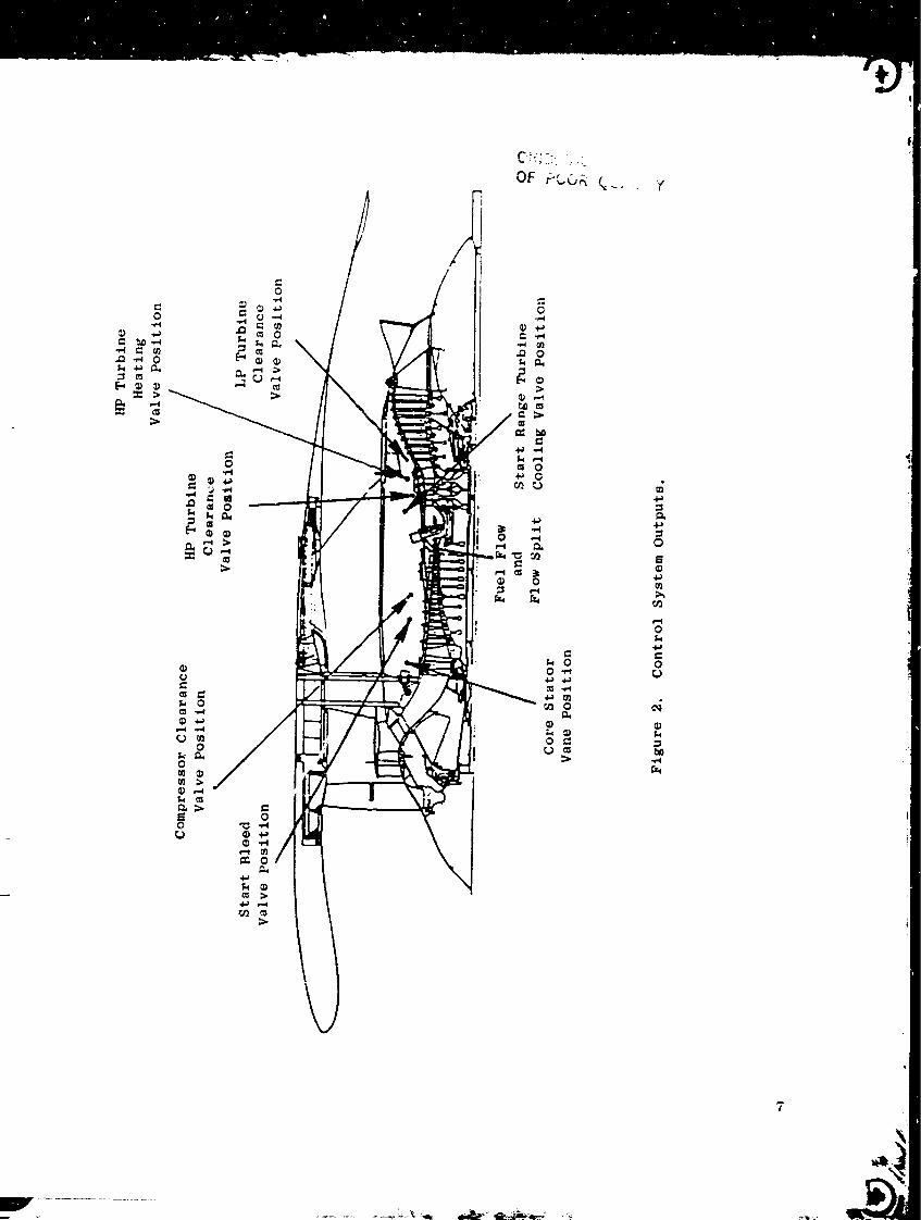
The design of the E 3 ICLS requires that the control system ha'Je outputs
as shown on Figure 2 and that it perform the following functions:
• Modulate fuel flow to control thrust.
• Split fuel flow to the two zones of the double-annular combustor.
• Position core compressor variable stators for best co_pressor per-
forma nce.
• Position air valves for independent active clearance control of the
compressor (Stages 6-10) and the I_P and LP turbines.
• Position the start bleed valves for control of core compressor 7th
stage air bleed in the starting region.
• Provide on/off control of the start range turbine cooling valves
which shift the cooling air source to account for reduced pressure
when the starting bleed is flowing.
• Provide condition monitoring data to the engine operating crew.
0
•Q'_ 0
0
Y
0
M
r/]
0
0
b0","4
W .................
7

4.0 BASIC SYSTEM STRUCTURE
Consideration of design requirements, _articularly the one regarding
digital electronic computation, led to the definition of a basic system struc-
ture as shown in Figure 3. The digital control is the central element in the
system. It receives input signals from the control room and from various
engine sensors, it provides servo signals to control the output devices shown,
and it receives position feedback signals from the output devices.
Figure 4 shows pictorially the inputs that are received from outside of
the control system. Seven temperatures are sensed including fan inlet air,
compressor inlet and discharge air, HPT discharge gas, and engine skin temper-
atures in the three areas where active clearance control is provided.
Air pressure inputs to the system include freestream total pressure which
is indicative of the average pressure at the fan inlet, compressor discharge
pressure, and a total-to-static differential pressure from the customer bleed
supply system. A pressure sensor is also provided for HPT discharge pressure
which _s a potential thrust control parameter. Current plans do not call for
the use of this pressure on the demonstrator engines.
Inputs are also received that are indicative of fan rpm and core rpm, the
latter being supplied from a core rotor-driven control alternator which also
serves as the primary source of electrical power for the digital control. The
control also receives 28 volt d.c. power from an external source for use dur-
ing starts at,d as an alternate power supply in the event of an alternator
failure.
Command data is provided to the digital control through a multiplexed
digital link which simulates an aircraft interface connection. The primary
command input is the position of the engine operator's power lever, but the
data link is also used to transmit adjustments and stlector switch positions
from a control room Operator and Engineering Panel which provides experimental
flexibility for demonstrator engine testing.
The data link also includes a separate channel for transmission of multi-
plexed digital engine and control system data to the control room, thereby

j I l_, I" I
X I
i- ..... "_I I_. I_ ,r f_
o
! o
L
! .
!
I!
JI
iI
_i_li
I
N
gu 00r,J
r./'j
0
o
co_._
I--I
9

/
ORIGINAL PAGE ISOF POOR QUALITy
10
simulating an aircraft engine monitoring connection. These data are displayed
on a CRT and made available for the demonstrator engine test instrumentation
system.
Control strategy for the various E 3 control _ystem functions is con-
tained in the digital control's program memory. Output signals are generated
by the control and then transmitted to the various actuation devices in order
to control them in accordance with the control strategy. Some of this control
is done on an open-loop basis, but most is done closed loop by utilizing elec-
trical position feedbac_ signals from the actuation devices. Virtually all of
the actuation is done with fuel-powered actuators using excess capacity from
the engine fuel pump through electrohydraulic servovalves which respond to
the digital control output signals. The only exceptions to this are the start
range turbine cooling valves which are air-powered through a solenoid valve
and the HPT heating valve which is a direct-acting solenoid valve.
Control outputs for the fuel valve and compressor stator actuators are
handled differently from all others in that they are transmitted to transfer
devices capable of providing switchover to hydromechanical control for these
two variables only. In the event of a digital control system malfunction,
fuel and stator control shifts to the hydromechanical backup plus all other
controlled variables are set at safe positions so that the demonstrator engine
will continue to run satisfactoril> and can be shut down in a safe manner for
correction of the malfunction_
Design details of 3ystem elements and system operation are given in the
remaining sections of this report.
II

5.0 DELIVERY AND CONTROL OF FUEL FLOW
5.1 FUEL SYSTEM DESIGN
In designing the fuel system for the E3, it was recegnized at the outset
that many of the considerations for establishing the highly successful fuel
system designs on current transport engines, such as the CF6, are equally
applicable to the E3. Therefore, the E 3 system was patterned after the CF6
system in many ways, with modifications made mainly to reflect the use of a
digital control and a significantly different combustor. A diagram of the
fuel system design that resulted for the ICLS engine is shown on Figure 5.
An engine-driven, positive displacement vane pump with an integzal cen-
trifugal boost element is used in the system for pumping. Pump discharge
fuel passes through a pump-mounted filter and into the fuel control mounted
on the end of the pump.
In the fuel control, fuel metering is accomplished by the combined opera-
tion of the metering valve and a bypass valve that returns excess fuel to the
inlet of the vane pump element. The bypass valve maintains a fixed differen-
tial pressure across the metering valve so that the metering valve area deter-
mines the amount of fuel flow supplied to the engine combustor. In the pri-
mary operating mode the metering valve is positioned by the digital control,
and in the backup mode (discussed further in Section I0.I) it is positioned
by the i_ydromechanical computer. A transducer on the metering valve provides
position feedback to the digital control.
Metered fuel passes out of the fuel control through a pressurizing valve
which is necessary co maintain sufficient pressure to operate fuel servos at
low flow conditions and through a cutoff valve which provides a means for
positively shutting off fuel to the engine. The fuel then passes through a
flo_m,eter (which is included to provide experimental test data) and an engine
lube oil cooler. Downstream from the cooler the fuel flow is split, part
going to the pilot zone and part going to the main zone of the combustor.
On/off valves in the main zone and pilot zone lines provide a means for modi-
fying local fuel-air ratios in the combustor under certain conditions as
explained below in the discussion on fuel flow split control.
12

!
13

5.2 FUEL CONTROL MODE STUDY
As one step toward defining the control strategy for fuel flow on the
E 3, a control mode study was performed (Reference I). The aim of the study
was to determine the engine variable (or variables) that should be controlled
by fuel flow in order to provide t_e best control of engine thrust in a large
fleet of engines, considering the variations 'hat will arise due to manufac-
turing tolerances, changing flight conditions, and wear. Consideration was
also given to ease of sensing and suitability from a stability and response
point of view.
The study was begun by establishing a list of potential fuel control
variables :_hich would indicate net thrust at _ny flight condition as a per-
centage of the maximum rated thrust at that condition (i.e._ a thrust parame-
ter). A candidate thrust parameter should be suitable for use in cockpit
indication and should correlate with percent-net-available thrust independent
of customer air bleed, control errors, engine component variations, and flight
cond it ions.
A list of the thrust parameters considered is shown in Table I. Eleven
of these thrust parameters are of the conventional type that utilize a single
sensed variable and a schedule for this variable The other three (TPIO,
TPII, and TPI2) are dual thrust parameters which utilize two variables to
provide _ome discrimination between control variations that can be ignored
and those component variations that cannot be ignored in setting power.
Earlier studies have indicated that such dual thrust parameters have the
potential for reducing the effects of engine-to-engine variations, thereby
reducing the amount of temperature margins that must be designed into engine
hot parts to account for these variations.
A key factor in setting up the control mode analysis was the definition
of tolerances for the _ndependent variables; that is, for the controlled vari-
ables in each mode being studied and for basic engine component characteris-
tics.
Controlled variable tolerance estimates were begun by estimating sensing
tolerances. Current state-of-the-art sensors were assumed with full-scale
14

Table I. ModeAnalysis "_nrust Parameters and Controlled
Variable Tolerances, Percent of Point.
Thrust Parameter
TFI - LP Turbine EPR (P49/PTO)
TP2 - HI: Turbine EFR (I'S3/PTO)
TP3 - P8/Pam b
TP4 - PSIS/PTO
TP5 - MII
TP6 - T41/TI
TP7 - Corrected Core Speed (PCNHR)
TP8 - Correc=ed Fan Speed (PCNLR)
TP9 - T49/TI
TPI0 - f(PCNLR, T49)
TPII - f(PCNLR, T41)
TPi2 - f(PCNLR, EPR)
TPI3 - WFE/PTO
TPI4 - PS/PTO
Sea Level
Takeoff Error
±1.60%
1.50
1.50
1.50
1.70
1.00
0.25
0.25
1.00
0.25, 1.00
0.25, 1.00
0.25, 1.60
1.00
1.50
_x Climb
(MXCL) Error
Math 0.632/
_.57 km (15K)
t2.30%
2.30
2.30
2.30
2.40
1.00
0.25
0.25
1.00
0.25, 1.00
0.25, 1.00
0.25, 2.30
1.00
2.30
15

ranges set based on the E3 cycle and flight envelope. Tolerance distributions
were optimized, _rheneverpossible, for certain scale ranges based on engineneeds.
The tolerance assignments also included analog-to-digital (A-D) conver-sion errors and estimated sampling errors based on the uncont_Jl_ed effect_ of
local flow distortions. Scheduling errors were estimated where secondary or
trim parame_ers were used to define operating values for the control vari-
ables. Error3 due to sampling, sensors, signal conditions, and A-D conversion
were combined by the root-sum-square method. All of the above factors were
combined to give the concroiled variable tolerances shown in Table I.
There are no_=ontrol factors that influence engine performance to a vary-
ing degree depending on the mode of control. These include engine component
variation due to manufacturing tolerances and service wear and also include
engine bleed and power extraction as required for anti-icing and aircraft
accessories. Table II lists the values used in the mode study.
The actual mode analysis is accomplished by using a computer deck repre-
senting the E 3 cycle under steady-state conditions. A special routine is
used with this deck to g,_ne _at¢ matrices of partial derivatives of certain
dependent variables with rezpect to certain _ :her independent variables.
Among the independent variables were potential control variables, air bleeds,
power extraction, and engine component performance variables which contribute
s%gnificantly to overall propulsion system performance. The dependent vari-
ables included such key cycle variables as thrust, sfc, temperatures, stall
margins, al.d roto= speeds.
The mode analysis consisted of a series of computer runs using the
matrices of these partial differentials. For each run a different control
variable was designated and a matrix was used that had this as its independent
variable. Predicted tolerances for se_sors, controls, and engine components
were multiplied bF the appropriate partial differentials. The_e effects on
the key dependent variables based on the square root of the sum of the squares
(RSS) were accumulated. Deterioration factors determined from actual field
experience were applied to the partials_ and the accumulation of these factors
was established.
16

Table II. ModeAnalysis Engine ComponentVariations, Percent of Point.
Vat iab ie
Fan Corrected Flow
Fan Efficiency
Core CompressorCorrected Fh_w
Core CompressorEfficiency
Burner Pressure Loss (P4/P3)
HPTurbine Are_ Corrected Flow
HPTurbine Efficiency
LP Turbine Area Corrected Flow
LP Turbine Efficiency
Fan Duct Pressure Loss
Postturbine Core Pressuce Loss
Compressor Interstage Bleed (% of W25)
CompressorDischarge Bleed (% of W25)
Shaft Power Extraction (Horsepower)
Core Engine Jet Nozzle Area (A8)
Bypass Duct Discharge Area (AEI6)
Nozzle Flow Coefficient (CF8)
Variation
±O.5%
1.0
0.5
1.0
0.5
1.0
1.0
1.0
0.5
0.2
0.2
1.0
1.0
25.0
0.5
2.0
0.5
Deteriorat ion
-0.5%
-0.4
0
-0.6
0
0
-I .5
0
-I .0
0
0
0
0
0
0
0
0
17

The results of the computer runs for the single-parameter modes are tabu-lated in Table III in terms of thrust variations caused by tolerance effectson new engines and deterioration effects. The modes are rated in order of
increasing thrust variations. The four best modeswere run ac other flightconditions with results as shownin Table IV.
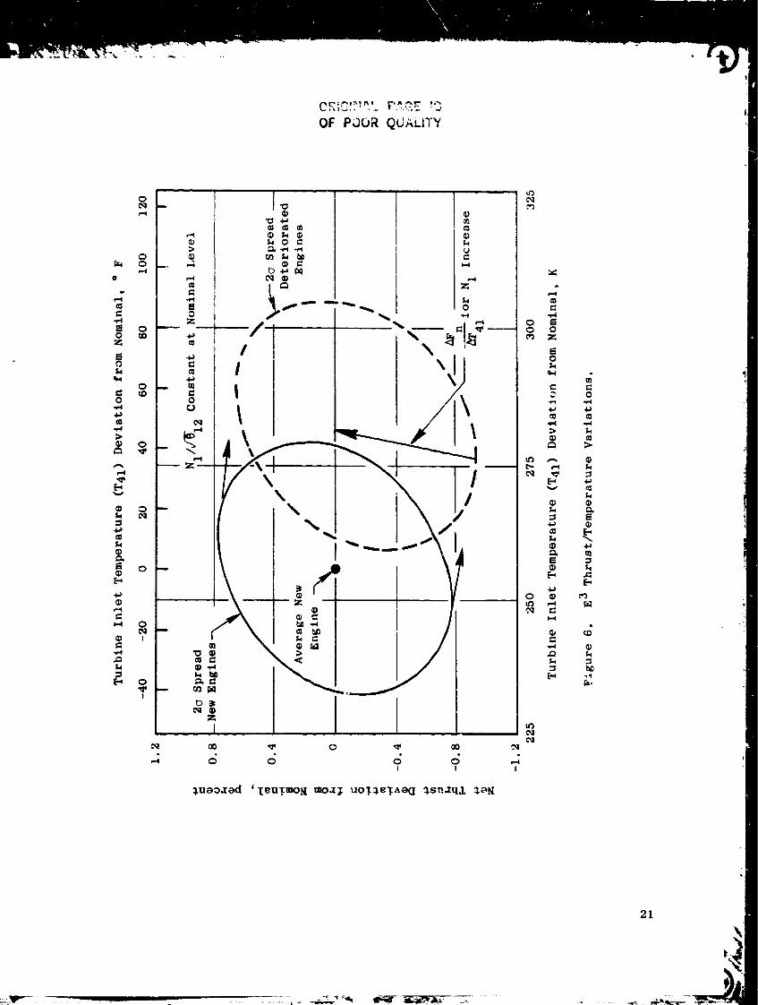
Typical results for the dual-parameter modesare shown in Figures 6, 7,and 8 which relate to TP!I. Figure 6 shows the statistical variations in
thrust and T41 resulting from new engine tolerances and deteL'ioration effects
if only half of TPII is utilized (that is, N1/,i_--_). In order to meet the
minimum thrust guarantee with all engines, it is necessary to set the thrust
parameter higher. This shifts the envelope of Figure 6 along the AFn/AT41
slope for an N1 increase resulting in the envelope shown on Figure 7 where the
maximum T41 i_ 311 K (99" F) higher than the original design nominal.
The basic idea behind the dual thrust parameter is that some hot engines
tend to be high-thrust engines (shown in Figures 6 and 7). Thus, it should be
possible to trade some thrust for some temperature and meet thrust guarantees
with less temperature spread throughout a large group of engines. This would
be implemented as shown in Figure 8 with the trim schedule designed to bring
all of the below average thrust engines on Figure 6 up to at least the average
engine thrust level. The net effect of this would be to limit the maximum T41
(the hottest deteriorated engine) to 305 K (89" F), 6 K cooler than without
the dual-parameter trim effect.
Results with the other dual parameters were similar to TPII. Thus, _he
benefits of the dual-parameter approach are small on the E3; since the is
some concern over the stability aspects of this approach, it was not pursued
further. On future, more complex engines the dual-parameters approach might
prove worthwhile.
As a final step in the mode analysis, several thrust parameters were
evaluated relative to the effects of increasing aircraft velocity during take-
off (takeoff thrust lapse). Of particular interest were net thrust and T41
for a fixed power lever setting with each mode.
Figure 9 shows the results of the thrust lapse analysis. The analysis
showed the expected loss of net thrust with increasing aircraft speed. It
18

Table III. ModeAnalysis Results at Takeoff and Maximum Climb.
Thrust
TPI
TP2
TP3
TP4
TP5
TP6
TP7
TP8
TP9
TPI3
TPI4
Parmmeter
P49/PTO
PS3/PTO
P8/Pamb
PSI5/PTO
XM2A
T41/TI
N2/,/F_
Nl/e/Fi_
T49/TI
WFE/PTO
P8/PTO
Sea Level _tatic
Takeoff
FT FD
±2.04% +0.06%
±2.43 +0.43
±4.20 +0.025
±5.26 -0.39
±2.74 +0.77
±3.79 -4.63
±2.73 +1.81
±0.785 -0.135
±4.33 -6.12
±1.25 -1.98
±4.20 +0.025
Rank
3
4
7
8
5
9
6
I
i0
2
7
,Max. Climb (MXCL)
!_ch 0.632/
4.57 km ([5,000 FT)
FT FD
±3.75% +0.b6%
±4.28 +0.98
±7.21 +0.51
±6.72 +0.I0
±7.14 +1.97
t4.84 -5.7Z
±3.78 +2.84
_1.73 +0.10
±5.53 -7.74
±1.45 -2,26
±7.21 +0.51
Rank
3
4
9
6
I0
7
5
i
8
2
9
FT
FD
ffi Thrust
=" Thrust
Variat ion Due
Variation Due
co Tolerances Effects
to Deterioration Effects
19

-- -7
d
t
]
_U
,=4
0
0_J
_P
g
0
°_,_
t.
O; POOR
w
0
0
0
t-
O,,._
r-
PAG_ i_
QUAi_I r_¢
2O
OF P_OR QUALITY
0
..i.,4
0Z
0
0.i,.4
¢1
>
i--I
.¢p
o
off
e-4
..Q
Cq
00
o,1
0
0
I
0
I
<:;I
_ueoaad _T_UTmOR moa_ UOT_T^OQ _snaq& _oK
O4
C_ Z
0
c 0
4,,a
=s E_
• d
_.,
21

ORIGINAL PACJI_ |S
OE POOR QUAL!_V
0
e-i
o O0
i-'4
c_
EtON
O Q
-6,)
4_
N
N
I11 Q
%
O
!
0
/
I
I
_uaoaod '[eUTWOK _oz_ UOT_eT_aCI _snzq& _o_
ce_
c_
e-4c_
0
0 ¢=
0
m ,,-i ID
r_
O,i
22

C": ?'
.... j i.,J
NI/,,/_I2 Comm +a_
JSchedulel
T41 Referenc_
Controller
N1/,/_-12 Sensed
T Calculated41
...J
T41 Calculated - T41 Reference - o F
i -40 0 40
. 0.4 ,! ! I'
Trim Schedule J
i_ 0.2
_ 0 ....
-_ -40 -20 0 20z
T41 Calculated - T41
80
I
40
Reference - K
6O
Figure 8. Dual Thrust Parameter Implementation.
23

I00
0
rlL _
OF_ POOk _,..
• Sea Level Takeoff
• Tam b = 303 K (89 ° F)
I
40
2O
3
04
"20
i Constant Core Corrected Speed
2 Constant Fan Corrected Speed
3 Constant Fan Physical Speed
--4 Constant HP Turbine Inlet Temperature _
5 Constant Core Physical Speed
E I
1
2
0.i 0.2
Aircraft Mach Number, Mp
0.3 0.4
Figure 9. Thrust Lapse Rate _nalNsis.
24

also shows that the selected control mode directly affects the thrust level.
Constant corrected core speed provides maximum thrust for the modes examined,
but also shows the greatest increase in RP turbine inlet temperature. Con-
stant real core speed results in the lowest net thrust and minimum temperature
at the HPT inlet. These results show the expected correlation of temperature
and =hrust in the engine.
Bince it is desirable to minimize the temperature increase for this oper-
ation, an approach which would maintain constant RPT inlet temperature is most
desirable. The single parameter mode analysis results indicated that constant
corrected fan speed produces minimum thrust rariations due to quality and
deterioration. It appears that corrected farL speed with an aircraft Math num-
ber or PTO trim should be used.
The final conclusion of the control mode analysis was that TP8, corrected
fan speed, is the most desirable thrust parameter for E 3. That is, a fuel
control strategy using fuel flow manipulation co control corrected fan speed
will provide the minimum variation in thrust due to engine tolerances and
de=erioration at key operating conditions. The analysis further indicated
that an aircraft Math number or PTO trim should be applied to the basic fan
corrected speed schedule to provide compensation for takeoff thrust lapse.
5.3 FUEL CONTROL STRATEGY
Having selected corrected fan speed as the basic fuel control parameter,
definition of the complete control strategy for fuel flow proceeded, and the
strategy shown in block diagram form in Figure I0 was established.
Fuel flow, for the most part, is modulated to control fan or core rotor
speed in accordance with the power lever angle (PLA) schedules shown as blocks
in the center and lower left portion of the diaEram. For ICLS, the schedules
are set up so that the core speed schedule is in effect from idle to approxi-
mately 30% thrust and the fan speed schedule is in effect _bove that, provid-
ing power management as a function of ambient pressure (PO), fan inlet temper-
ature (TI2), and Math number (Mp).
Limit_ are imposed on the basic schedules to prevent excessive RPT inlet
temperature (calculated), excessive LPT inlet temperature (T42), and excessive
25

o I
o
r_
e,4
0
0
0
m
26

compressor discharge pressure (PS3). In addition, transient fuel schedules
and limits are included to (I) prevent compressor surge during rotor accelera-
tions, (2) prevent loss of combustion during rotor decelerations, and (3)
limit thermal shocks (by limiting fuel flow rate-of-change), l_e schedules
and limits are combined in a selection network which establishes priorities
and assures smooth transition between control modes. A manual input is
included to provide the capability of adjusting fuel flow from a control room
potentiometer to explore subidle engine characteristics.
The control will have the capability of sensing customer bleed airflow
from the compressor and applying appropriate compensation to the acceleration
fuel schedule. For the core and ICLS this will be an optional fe_nction which
can be deactivated by means of a control room switch.
The output of the selection network is a fuel metering valve position
demand that operates a position control loop to position the valve, thereby
setting the desired fuel flow.
5.4 FUEL FLOW-SPLIT CONTROL STRATEGY
The E 3 double-annular combustor shown in cross section in Figure II
requires that fuel from the main fuel metering valve be split between the
pilot and main zones. The required flow-split characteristics are listed
below.
Start Mode- Full fuel flow is required to the pilot zone to assure
ignition and best combustion during acceleration to idle.
Alternate Start Mode - If high compressor bleed flow is required for
starting, acceleration to idle with pilot flow only may create an intolerable
turbine inlet temperature level and profile combination. To cover this con-
dition an alternate control mode is required that provides pilot fuel only
for ignition, temporary pilot leaning after ignition to get main zone igni-
tion, and a uniform split after main zone ignition for best temperature pro-
file during accel to idle.
Run Mode - Full fuel flow to the pilot zone is required at idle when not
in flight to provide minimum exhaust emissions. Above idle or in flight, fuel
is required to both zones.
L

". .".t -C,
__--P ilo t Dome
Dome
Figure ii. E3 Double-Annular Combustion.
28
Decel Mode - Temporary switchover to pilot-zone-only flow during rapid
deceleration is required as an experimental option for use only if decel blow-
out problems are encoun=ered.
Transition - For transition to full burning mode, main zone flow must be
t_porarily held low to prevent pilot starvatio_l as main injectors fill.
The control strategy designed to meet these requirements is shown on
Figure 12. The block at the upper left provides the basic on/off logic for
the main zone shutoff valve, including the alternate start mode logic, and
the blocks at the bottom provide the pilot zone reset that is a part of this
alternate mode. The blocks in the cer,ter provide the main zone throttling
function to prevent pilot zone starvation during transition to full burning.
The duration of throttling is varied as a function of total fuel flow as indi-
cated by main fuel metering valve position and as a function of the time since
last main zone operation.
The decel mode logic is shown in the block at left center. An adjustment
on the deceleration rate required to trigger this mode is provided so that
this function can be modified or deleted altogether from th_ control room dur-
ing engine operation.
A manual mode is also provided for both the main zone shutoff valve and
the pilot zone reset valve which allow each valve to be independently posi-
tioned from the control room during engine operation.
T._e output of the main zone sh,ltoff logic network operates the main zone
valve through a control loop that includes position feedback so that the valve
can be set at any position from fully closed to fully open. The _ilot zone
reset valve servocontrol does not include position feedback so this valve can
only be set fully open or fully closed.
5.5 FUEL CONTROL LOOP DETAILED DESIGN
Design details of the fuel control strategies just described were defined
primarily on the basis of predicted engine cycle characteristics using data
from the computer model of the engine at steady state (cycle deck) and data
from transient computer models derived fro_ the steady-state model.
2_

o
ORIG!NAL P#,._E .T'::
OE POOR QL:,%LITY
_ NN
l
Ii .
o.
@
tJ
_ 2
=
_2_
-=_.=i
! ------t _
?_: i=iI
.... t"
L.J
r-7
• I I
L_J
. t
E= ,=== ,
D _j
== r=7 r-7 _
i,,lI_ ®I
_.=J 1_9_l o _-I
s
o _
or]
r7 rj-_-- _ r-7 ,.
_r_ I _ I_
u:.
¢10
4.J
,-4
o
4.1
=o
u
P_
r./3
o
;z.
_a
30

The basic fuel control system schedules of core and fan rpm as functions
of power lever angle were d?_igned so that the .elationship between angle and
thrust is nearly linear at ICLS operating conditions. The schedules, shown on
Figures 13 and 14, are designed so tLat the corrected fan rpm schedule is nor-
mally in effect above approximately 70 ° power lever and the corrected core r_m
schedule is in effect below.
The dynamic characteristics of the fuel control loop were designed by
the use of linear stability analysis techniques and by the use of a transient
model of the engine and control on a hybrid computer.
The transient engine model was based on the E 3 steady-state cycle deck
with component subroutines programmed directly from the cycle deck source.
The block diagram in Figure 15 shows the information flow through the model.
The diagram consists of blocks connected by flowpath techniques. _nese blocks
represent the component subroutines just noted. Each block is identified by
the engine-component thermodynamic function represented therein. Inputs to
the engine components on each pass include flight con_litions, iteratio_ vari-
ables from the iteration logic, rotor speeds from the rotor simulations, and
control variables from the control simulation. Compressor bleed and horse-
power extr=ction are not shown but are included. Separate blocks represent
inputs and outputs for the iteration logic, rotor simulations, and control
simulation.
The stability analysis effort and the transient model work resulted in
control system dynamic characteristics that produce the engine transient char-
acteristics shown in Figure 16 which is a set of data traces showing a fast
deceleration _-llowed by a fast acceleration on the transient model.
The dynamic design work just described was limited to the region above
idle because the engine cycle deck and transient model are limited to that
region. Therefore, a separate subidle engine model was prepared to aid in
designing the transient characteristics in the starting region. This model
was patterned after a similar subidle model for an existing engine and adjusted
to match predicted E 3 characteristics at idle. It was further adjusted when
actual subidle data became available fr._m component testing of the compressor
and HP turbine.
31

.,r _-,j_ _,,ALII'Y
I
I ..... I .....
AS
0oo3
o3
tl
Or-4
J_
O
cq
C_
t_
_D
0
0
_J
u_J
0
32

OR'_-':_ '-' _LOF pOOR _tjA_tT
CD,-4r=d
I
" i' , •
A
O
oi
I!
O
v
OC_
..i
O_ 00
_uao_ad 'p_d S a_oo pe_0azxo3
Ot',*
ii
O¢,D
O
O
Oe..4
t_
o_D
O
Q
cq
O
0J
0J
0_J
"o
0
0
"o
_J
0J
q_
0
q_
33

ORIGINAL "
r-"
÷
2_i
0
0
e_
.4
34

:I[[I[I[![IIITI;I! _ • [1 ; !! '' t ! _I_i_ ;:
, T ilt !I ;i_+t :ii .... ,i,i,,; ,, !1; :!< ;_T: _ : _ ] ' ''-- " "+_) ! [ I i t 1 I I t i i ! , i " T , _ : • +__ ' ....
:l[[[l!iIIli:[;];!tI:!llli ''!iT _;+ [| ]''l _ _l i 11 _iI:_l:]l}:i'_l''_'Iil.... '" " _ _;,_;'_::' _ F"
o._J.__!+__L,.l__L.l.'l_+i..__.i._.i_a .... 2,_,LIJ+LLI,L,:_____.____: : _.
i ' i _Tril_r I I i Ii l! i : i ' ': ..... I '-'-"-_-' _ _- "-. i I _I dlllli i i]' , ,+r_'--'--_'-*l_i+--_ -" 4"--
.... l+ I I ' , ..... ,+_l--f---+--4--_ ....,it .... I ; ++ • l It+-+l +,.1'_-,,i-4__ ilii:tiltll:;];'ll!llll!i!ti+, , :_i:, -+__
''![::iTZ,'P"*"4"-.J]!]!:]7::T;:I{| llrIlilll][l_i T _ ,.:_ ;....+-- : '!''?
, I l_ :;_! .I I ._--"'_._-.+ i,_[,ll 7 , .i _ i '_i:l_l[ I,]'liii'=lJtiit_ ;tl'I! _:': _ '-- +' ,_ _<-"'_'+: t _ I t ! I t] [ 1 :_] [ i + ! i [ i !_i I i i i i i + i i i I ! i±L_ ; + _ ' + ' -'--+-+'-'-+ + _ ' " ' ' _ ' ' '
t,
_._o 7 [ : ! ! ! ! i i: J i L : , ' l ! i , , 1 t , . | _ . i : , .
. + r +I , ..............+ , /I . • I . , , + + , , i _ , : .+W_' , ,
. '1 , :; : t ' ; i : if- L + ! [ 1 + [ 1 : i L; . ; .--! : ....... l _ " "
o _<_,.u_i_u+_,:i., : !_'' ': .... + + ;'''-_ ....4 ........ :-:-E .....
, ,i , . + I + t : . i . ; ; : : _ I + + ; + i_ _ ! i . t . . , +._.+. + ..... '
-+-_ I _ ; f _ _ ! + , ', < ! _ " ; r' ', ; +' i _ ! t ! L";-4-4--_::2"_: i - ..........
•P+,,l l : : ] T i"+_ : e : [ _L. q : ] : :,+ i : i l ! '. I : :/ I 1 ' --I-" + + + - - ' :
0 i i , + I i i +_+,,._ ' _-L-,--_ + _ : : ..... , ,t-...... .. +
__._+____ . t . +_ ...... : . . _ . . : ± i . ; : . _. ! , : _ , _ - , '. +_+__+__' : LI + .,,t,_' _'--+ i ' i i + + ; , : + [ [ i i + : , ; i : : + i , : + i _- 1--,-t-i-_ I : _ if ::6: ._,"-._+.. . . : .,-.+.... : , ,: !i-2:-- i:t:. --;-.--i_ ......
- _ +i : + -,,.: ! , , I+ , ,.,i ,, : t ' '' _: _I'A'-! i+' '' ! _ " _-
l r _iil_lli$lliLll ? ........... IrlilI l. ll.l.l illfllID I illlllT!, {llll;llT I ! I) .. ...................................... .------.+----.
Figure 16. Hybrid Model Transients.
35
It

ORIGINAL. , ....OF POOR QU, :-_ ;"_
tIT=,"ZA ] . , .
• 25, , I
!,..2j. ,J
Ii, ,", i':';.-- °
_ o I 1 a i ' ' ' ;
-21 ,
, T -
I"7_mo I ] • , - i
T
/ l ; ,, _ , ,!
",7.=,-I_=_ ...... i ' • I i 'l
Figure 16. Hybrid Model Transients (Concluded).
36

Figures 17 and 18 show typical subidle model data pertinent to control
of fuel flow and to choice of a starter. Design objectives call for a 60-
second start on a standard day, while maintaining at least 10% compressor
stall margin and limiting turbine inlet temperature to 1228 K (1750 ° F) maxi-
mum. A preliminary fuel schedule meeting the latter two criteria is plotted
on Figure 17 and the resulting core rotor torque characteristic is shown in
Figure 18.
Work with the subidle model is not complete as t_is report is written
because additional component test data remains to be obtained. However,
based on early subidle model results, the E 3 has been designed to use two
Hamilton Standard PS600-3 air turbine starters, the largest readily available
starters of this type, in order to assure meeting the 60-second start-time
goal.
37

5
o"4a
==
4
0
m
o 3
15
ORIGI_AL p/_3_Z IIIOF POOR QUALITY
Show Start Fuel
Schedule (Prelim)
SteadyState
13O%
I20 2S 30
Fuel Schedule Parameter (W]F/PS3), pph/psiJ
35
Figure 17. Subidle Model Datl.
38

60O
OF POOR QUALtTY
,,Q,,-I
D"
0
"O¢)U=O_
r-4O_
=
400
200
0
-200
-400
/After Ignition
with Prelim
Fuel Schedule
of Figure 17 --
0 20 40 60
Corrected Core Speed, percent
Figure 18. Torque Data from Subidle Model.
80
39
6.0 CONTROL OF COMPRESSOR STATOR _ANES
6.1 COMPRESSOR STATOR ACTUATION AND CONTROL
On the core and ICLS engines the compressor IGV's and the first six
stator stages are variable and ganged by a system of levers and annular rings
around the compressor so that the stages move simultaneously with a stage-tc-
stage relationshlp established by linkage characteristics. As shown in Fig-
ure 19, the linkage is operated by a pair of fuel-driven ram actuators that
are normally controlled by the digital control through an electrohydraulic
servovalve. Position feedback to the control is prcvided by a position trans-
ducer connected to the actuation linkage. In the event of a digital contr_l
system failure, control of the stator actuators transfers to the hydromechani-
cal control which provides a basic schedule similar to that in the digital
control. This is described further in Section I0.
6.2 COMPRESSOR STATOR CONTROL STRATEGY
The conventional practice of scheduling compressor stator angles as a
function of rpm and inlet temperature is used for the E 3, but the added com-
putational capability offered by the digital control is utilized to supplement
the basic schedule and to further exploit the potential of variable stators to
improve engine operation and performance.
Figure 20 is a block diagram of the stator control strategy. The basic
schedule is shown in the next-to-top block on the left with the modifiers
applied to it through downstream summations. The modifiers are described
below.
Approach Reset - This feature in effect provides an alternate schedule
that closes the vanes much further than normal in the approach thrust range.
This results in higher core rpm during approach, thus making it possible to
regain high thrust more quickly in the event of an aborted landing. This con-
cept, tried briefly during the NASA/GE QCSEE program, is included in the E3
program so that it can be explored further.
4O

OR,G,,,.AL P;"-9_ !g
OF POOR QUALITY
_ ---I
I
II!
• • , , _
I l |
i
f-I !
[-'4 _ /
F, L / I I
I _ m_
o
0
0
0_
0,i-I
0
o
t_
0
0
0
t_
41

<
,,,.1
Z
2
O
,..1
O +
r
= +
< <
i 01I °_ i
ZO
E-,
u3UO<_._¢_
,.,.,,
.¢
E/:z
OF p_CjR QUALtT¥
_.,r.
o _'_ _3=rj .,,_ _..J :.,3
=_;
r_
C._ ¢,zZ
_ =¢.,3
Z_; _ .
_8 °° "-°
0,,,a
<
..1
U
/
vl
t
0
gll
/_o
_l_ _
=IL.) e,_ L -
Z _
_ , r,.
r,, ,F.,
¢=
O3
O
0
0
r./'j
0
o
42
- ,,_.j_._ _ ."

Rain Reset - Experience with CF6 engines has shown that heavy rai:_ cause_
a reductlon in compressor inlet temperature (T25); rapid termination of rain,
combined with T25 sensing lag, can cause compressor stalls. This reset causes
a small stator vane closure when sensed T25 is less than calculated T25 (as it
will be in heavy rain), thereby increasing stall margin.
Speed Match Reset - Experience has shown that engine deterioration often
results in a reduction core rpm relative to fan rpm and a corresponding reduc-
tion in core efficiency at cruise thrust settings. This function detects a
deviation from the normal core rpm/fan rpm relationship and adjusts the stator
vanes to restore the original relationship.
Bleed Reset - It has been proposed tha_ a stator vane reset might be used
to adjust the compressor operating point and to improve efficiency when cus-
tomer bleed air is being extracted. This function is included to allow inves-
tigation of this concept.
Transient Reset - The basic stator schedule is designed to provide opti-
mum steady-state compressor performance. But it is not necessarily the best
schedule for rotor speed transients. For this reason, a transient schedule
reset is proposed to provide improved transient characteristics. Because
stator effects on the E3 compressor are not yet accurately known, analytical
definition of the reset is not presently feasible. Based on past experience,
it is expected that a stator reset in the closed direction will provide addi-
tional transient surge margin and better transient characteristics. A reset
proportional _o the rate of change of speed is incorporated for empirical
evaluation.
Switches are provided as shown on the block diagram (Figure 20) to allow
the above modifiers to be disabled during the test program so that they cannot
interfere with normal stator scheduling. Also, adjustments are included (not
shown on diagram) to eliminate the effects of individual modifiers.
43
7.0 CONTROL OF STARTING BLEED
7.1 START BLEED ACTUATION AND CONTROL
The E3 incorporates provision_ • for bleeding air from the compressor
7th stage in order to compensate for flow mismatch between the front and rear
stager at low speeds during _ start. This bleed flow is controlled by a set
of four butterfly valves that are connected in parallel as shown schematically
on Figure 21. The valves are incorporated into four radial air pipes ;hat
connect the Stage 7 bleed manifold with ports on the inner wall of the fan
duct. The actuation ring that connects the valves is driven by a single fuel-
powered servoactuator; the control signal for the servoactuator is provided
from the digital control. An electrical position transducer is incorporated
within the servoactuator to provide feedback to the control.
7.2 STARTING BLEED CONTROL STRATEGY
The automatic control strategy for the starting bleed calls for position-
ing the valves, thereby controlling bleed flow as a function of core-corrected
rpm. This is shown in the block diagram, Figure 22; the initial schedule is
shown on Figure 23. Scheduling flexibility for the te_t program is provided
by digital control adjustments of the open flat and the location of all break
points on this schedule.
In addition, a manual control mode for the start bleed valves is prowided
to allow experimentation during the eT!gine test program. In this mode, the
bleed valves are positioned in response to a potenti,_meter on the digital con-
trol operator panel in the control room.
44

6
0
G0r,)
_:_q3
4=J
d5

OH;:51NAL PAGE IS
OF POOR QUALITY
Lq
,.-1Z
(3
C;
0
0cj
U
I--I
0
\ /
46
_:> 0_ ,...1 :::>
_Oo __ m
L bI
,.-1
+
U
r./l _:1 r._
Z0I,.,.4
_0
,-__ _ _.._
J
z_
Z_
_o
0
=o
,._
b_
_4C_
@
_3

5O
4O
_N
= 30a=
¢)
0
20
4_rat
lO
0
2O
PCN25R,
%
30.0
40.0
50.0
i
Area, \
- in2 _ -
6.85 \
4-90 \ -
,0. O0
30 40
PCN25R, percent
Figure 23. Starting Bleed Schedule.
50
6
c*m
e_
5
4
_o
3
bO
0
47

8.0 CONTROL OF START RANGE TDRBINE COOLING
8.1 START _RANGE TURBINE COOLING MECHANIZATION
One of the effects of the starting bleed just described is to lower pres-
sure levels throughout the compressor when the bleed is open. This has a cor-
responding effect on the pressure level and on the flow of air extracted from
the compressor and piped externally to the turbine region for cooling and
internal pressure control. Figure 24 shows these parasitic flow systems sche-
matically. A small amount of Stage 5 air, also used for compressor clearance
control, is piped into the LPT purge manifold and used for internal pressure
control in the LPT rotor. Also, a small amount of Stage 7 air is piped to
the Stage 2 HPT stator for cooling.
In order to maintain adequate pressure and flow in the parasitic air sys-
tems during a start with the start bleed valves open, provisions are made to
temporarily connect these systems to a higher pressure source. A pair of air-
actuated on-off valves and a system of check valves allow compressor discharge
pressure to be applied to the parasitic systems when the start bleed valves
are open. Actuation air for the two start range turbine cooling valves is
controlled by a digital control-operated solenoid valve.
8.2 START RANGE TURBINE COOLING CONTROL
Two control modes are provided for the start range turbine cooling, one
automatic and the other manual. In the automatic mode the source for the
parasitic air systems is selected as a function of core-corrected rpm. Below
ground-idle power the systems are connected to compressor discharge pressure;
at ground idle and above, they are connected to their normal sources. A
slight delay in closing the start range turbine cooling valves is provided
upon reaching ground idle to prevent any undesirable compressor discharge
pressure disturbances before steady-state operation is achieved.
In manual mode, start range turbine cooling valves are controlled solely
by a switch on the digital control operator panel.
48

z_o_.-4c_ f.r.. Z_ZO
_0_
I !
z0
49

9 . 0 ACTIVE CLEARANCE C 3NTROL
9.1 ACTIVE CLEARANCE CONTROL MECHANIZATION
There are three separate active clearance control systems on the E3:
one for the aft stages of the compressor, one for the HP turbine, and one for
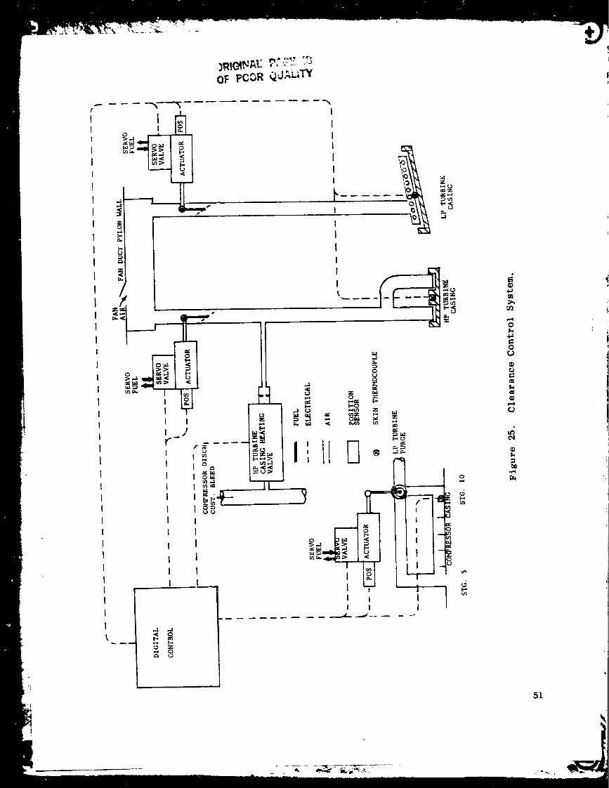
the LP turbine. They are shown schematically on Figure 25.
Clearance control in compressor Stages 6 through I0 is achieved by pass-
ing a variable flow of Stage 5 bleed air over the compressor casing in this
region to provide a thermal adjustment of casing dimensions. The Stage 5 air
extracted for LPT purge is ported so that it can flow through the compressor
clearance control chamber and through an external bypass pipe. Air from these
two flowpaths is ported to a rotary three-way valve which is designed to pro-
vide virtually constant total flow but a flow split between the two flowpaths
that varies with valve rotor position. The valve is positioned by a fuel-
operated servoactuator controlled by the digital control. An electrical
transducer within the actuator provides position feedback to the control.
Turbine clearance control is achieved by impinging variable amounts of
air, independently, onto the HP and LP turbine casings to provide thermal con-
trol of casing dimensions. Both systems utilize fan discharge air picked up
by scoops in the fan duct pylon wall and passed through variable area butter-
fly valves. These valves are independently position_d by fuel-operated servo-
actuators similar to the on_ used for compressor clear_nce control. The HPT
clearance control system also includes a provision for introducing compressor
discharge air onto the casing. Studies, using the clearance model described
below, revealed the desirability of using this air for a brief period immedi-
ately after engine start in order to establish proper clearances quickly and,
thereby, eliminate the possibility of a rub if the engine is accelerated
before the casing can heat up naturally. The studies showed a similar feature
which was not needed for the LP turbine.
5O
t
t
OF PCOR Q_._L_W
.... --,_----.._
___ I _ I
/
_ I L_
<¢
t ,,,J t,J
,_,_ I ''_ <
u'J ,,..1_- ,K <¢ I
I
IIIIII
1"-Z
¢¢1Z
1I
I
II
I
J_m
/':=
O_r_,,j
Z
_ 6
[-,0Z
I
III
I
0P,
p,
fl!
|
1
ee_
0
i
I
!1 !-
I
0
0
.4
51

9.2 CLEARANCE CONTROL STUDIES AND CONTROL STRATEGY DEFINITION
The process of defining a control strategy for the clearance control
systems began with the establishment of a set of general objectives as listed
below.
• Provide minimum practical clearance at cruise power settings.
• Provide .extra clearance for takeoff/climb maneuver deflections.
• Prevent hot rotor reburst rubs.
• Fail-safe (i.e., to maximum clearance).
• Provide manual remote control of clearance air valves for core/
ICLS experimental flexibility.
In proceeding with the task of defining a control strategy for the clear-
ance control systems, consideration was given to the use of direct clearance
sensing to provide feedback information to the digital control and thus allow
direct control of clearances. Clearance sensing on an operating engine has
been demonstrated on an experimental basis, but the methods are not far enough
along in development to make them feasible for use on initial E3's. Thus, it
was necessary to develop a control strategy that does not depend on clearance
sensing.
To assist in the definition of clearance control strategy, mathematical
models of the engine and control elements involved in active clearance control
were utilized. A generalized model was established which uses rotor speed,
altitude, and Mach number as its inputs and which combines dynamic representa-
tions of internal flows, heat transfer, thermal growth, a-d mechanical growth
to arrive at calculated clearance values. A diagram of the generalized model
adapted for the compressor is shown in Figure 26.
The engine model is a compilation of corrected parameters representing
the pertinent cycle interfaces (T25, T3, P25, P3, P8 for the compressor) as
functions of corrected core speed (KNHR). Included is a derivation of the
pressure and temperature distribution in the engine flowpath at each stage.
The cycle variable tabulations are for specific altitude and Mach numbers and
are generated as a cycle deck operating line. A procedure was established to
_J
]
52

ORIGINAl- P;_ _-_ _3OF POOR _d-_,k' ''r'_ A r
•"'T" ,
!lI
IA I
[]IN
IN
L
0
m
I
C
"z,,I
,, i
__al ml all
,_1 ®1 ®tOl Ol ol,_1 ,_1 ,_1
1,ii
t,)e,
_d
S3
convert cycle deck output to files of tabulation that are readily incorporated
into the engine model.
The bore environmental model establishes the transient temperature dis-
tribution in the bore flowpath in a stage-by-stage thermal analysis of the
disks. Each disk is simulated as a nodal pair (bore rim) for this purpose.
The routine includes an iteratiop on bore flow level, which depends on the
bore path exit temperature.
The rotor environmental model incorporates a representation of the imme-
diate neighborhood, fore and aft of the detail stage disk. It invokes the
bore enviromnental model to establish bore path conditions at the detail stage
from which the pressure end _emDerature distributions in the interdisk cavi-
ties are determined. The convectance and temperature at each disk node site
is established for the detex_ination of nodal resistances in the rotor/blade
thermal model.
The rotor/blade thermal model uses the resistance values from the rotor
environmental model to calculate the node-by-node temperature distribution in
the rotor disk. The resistance/capacitance values at each disk node are :on-
strutted from boundary resistances (convectances and conductances) and inter-
nal conductances. The blade is thermally coupled to the engine flowpath arid
through the shank to the disk rim node.
The rotor/blade growth model is used to calculate the radial growth of
the rotating parts. The radial growth of the disk is calculated as a function
of radial load at the rim, temperature distribution, and angular velocity.
Growth of the blade is determined by t_e conventional relationship:
= &a (T-To)
where T is the element temperature, To the temperature at assembly, & the
blade length, and a the coefficient of thermal expansion.
The clearance control model schedules and determines the impingement
cooling air supply. The shroud model includes interaction with the engine
flo_-path and provision for i_pingement cooling of any designated casing.

Transient effects for the impingement air were also modeled. Thermal growth
of the shroud is determined in the samet,anner as blade growth. Then, clear-
ance is simply the shroud diameter minus the rotor/blade diameter.
The generalized clearance model wasvalidated through the use of CFM56
compressor clearance experimental data gathered during engine running. TheCFM56ch_ acteristics were introduced into the model and the model was run at
the conditions existing when the experimental data was taken. Initial runs
revealed that someof the model representations needed refinement. After the
refinements were made the model matched the experimental data for both transi-
ent and steady-state conditions. It wa_ then considered suitable for trans-
formation to E3 compressor and turbine configurations and for use in explor-
ing E3 clearance control system characteristics.
Typical data from the E3 clearance model is shown in Figure 27. This
happens to be for the RPT, but it is typical of all three systems. It shows
that the system is capable of modulating the steady-state clearance at takeoff
conditions from 0.279 to 1.346 mm (0.011 to 0.053 in.) with the fan air bleed
flow within the range established by engine cycle considerations (0.3% of core
airflow, maximum). This figure also shows that clearance during and immedi-
ately after a rapid rotor acceleration with a given amount of cooling is much
less than the steady-state clearance with that same amount of cooling. The
maximum cooling condition shown actually results in an interference at the
end of the acceleration. In order ,'o eliminate the potential for such inter-
ference, the model data suggests that a limit must be imposed on cooling as a
function of rpm. Figure 28 shows just such a limit.
As might be expected, the model also revealed that an orderly relation-
ship exists between steady-state clearance, casing temperature, and rotor _pm
(shown by the solid lines in Figure 29). The characteristics shown here sug-
gest that a schedule of casiro temperature as a function of rotor rpm could
serve as an indirect method of controlling clearance. A trajectory for such
a schedule is shown on Figure 29. The trajectory was established on the basis
of the following criteria:
• Set the desired miniml_m running clearance of 0.406 cm (0.016 in.) at
maximum cruise conditions.
55

0up
"[
00
0Z
HPT Rotor Tip Clearance, mils
ORIGINAL PAfll_ lq
OF POOR QUAL+TY
/ ,7-,'- t.;'] I
/,,'!.i!
m _
i
1
o+
o
o
F
i_
_n 'aoue_eoID d!_ ao%oM /_IB
oo
• o%
o
u_
o
_D_a
I
=
o
,%
N0
,,,,4
4--
0
0
o=
;+
0
=
z_
m
=
m=
cq
h0
56
5_: ,L_ _
i

HPT Rotor Tip Clearance, mils
CR,_,NAL PAC-_ I_OF POOR QUALITy
C3
II
{
(
//
/
/
/
o o o 0
/
/
//
,I/
/
//
/
//
/
//
o
00_
oo
o
%
o
o
o "o
>
0
c_
oo
c_o
0
oo<
o
z_
o
b_
_m 'eou_aID d_l zolo_ /x_
5?
w_

I
f-
¢C
Z
I
o
CP
0o
r_0 O
u_
t_
KPT Rotor Tip Clearance, mils
\
c;c_
c_
U
0
G0U
_J
U
g
E
oj
o,I
Q;
58

• Provide additional clearanze up to 0.635 mm (0.025 in.) at takeoff
and climb conditions to accommodate maneuver deflections.
• Set additional clearance at lower cruise power settings to prevent
inadequate clearance transiently after an acceleration.
• Provide maximum clearance at power s_ttings bel,_w cruise to provide
ample margin for accelerations. (Very little cf the total engine
fuel consumption during normal flights occurs .n this power setting
regio_; thus, the extra clearance margin has _.egligible effect on
fuel use.)
The initial schedule derived in thi_ manner is shown in Figu:e 30. Note
that the schedules are defined in terms of parameters corrected to core engine
"inlet temperature. Similar schedules were derived in the same manner for com-
pressor and LPT clearance control.
In order to assess the transient effects of scheduling ca_ing temperature
(and thus steady-state clearance) in the mariner jus_- described, the schedules
were incorporated into the clearance model and transients were run. Figure
31 shows typical data from the HPY clearance model during an acceleration.
This data reveals another desirable characteristic of the casing temperature
scheduling concept. For nearly three minutes after _n acceleration from idle
to takeoff power, the casing temperature is below schedule and t_e clearance
control valve is closed. The thermal characteristics without casing cooling
are such that clearance remains in the 0.635 to 0.762 cm (0.025 to 0.030 in.)
range, thereby providing the additional margin desired for the engine deflec-
tions that occur during takeoff and initial climb.
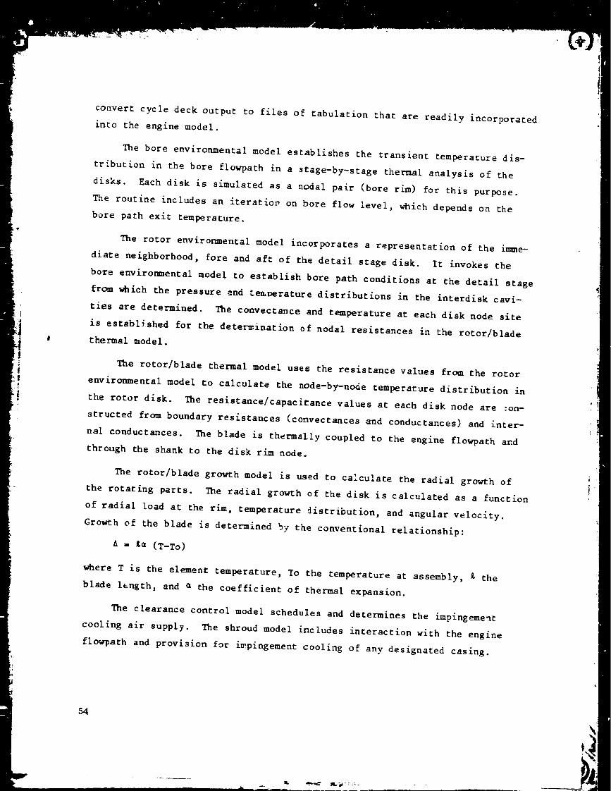
Accel transient runs on the compressor clearance model also revealed an
interesting characteristic. As shown in Figure 32, the temperature of the
Stage 5 clearance control air is higher than casing temperature for about a
minute after an acceleration from idle to takeoff power. By rotating the
clearance control valve to the maximum casing flow position during this
period, casing growth can be accelerated to help p;ovide the extra clearance
margin desired for takeoff and initial cl_mb. A model run showing the effect
of this feature is shown in Figure 33.
59

Casing Temperature, o F
oc
ORIGINAL PAGE 111OF POOR QUALITY
6O
I>0u3t',-
I
)I ' a._n:te.zedmej_ _uTse3
b_
Io
.

. >.
ORIGINAL PAGE |S
OF POOR QUALITY
Temperature ° F
o o o oo o o o
4.Jo_-J o
u3
_un o
_3 c/3
\\'I\\!
00 r-- _c
o
Lf_
I
Clearance, mils
o
ttm_ '_Dueae_iD
Q
.,I-
4,J
if,
q_
61
ORIGINAl.. PAGE
OF POOR QUALITY
Temperature, o F
Stage 9
Rotor TipClearance,mils
o o o
_0r-4
_J.4
t_
o
m
o
62

700
65O
L$
o
= 600
m_E
550
500
_--iS? _---_--------;i:_°_:n:::Itr°l (No Casing CJoling)__
800
700
f_
600
500
0.8
0.7
== 0.6o_
0.5
0.40I
Casing --
-_._ Airflow __
Modulated
29 40 60 80 i00 120
Seconds After Start of Acceleration
140
30
c) co
tDI_ QQ
25 o=_
20
Figure 33. Transient Compressor Clearance With and Without Control.
63
With the casing temperature scheduling concept successfully demonstrated
on the clearance model, detailed clearance control strategy definition pro-
ceeded. Figure 34 is a block diagram of the strategy for the HPT clearance
control systems. Tbp basic casing temperature scheduling function is shown
in the upper left part of the diagram. The decel override shown below this
was added to prevent rubs in the event of hot rotor reburst (that is, a decel-
eration followed by an acceleration before the rotor, which cools slower than
the casing, has reached steady-state temperature). A rapid deceleration
causes the clearance control valve to close and remain closed until the casing
temperature reaches the normal steady-state level. If the engine is reaccel-
erated before steady-state temperatures are established, the decel override
is deactivated and the casing temperature schedule functions normally.
A manual control mode is also provided. When the manual mode is selected,
the air valve is positioned as a function of a potentiometer on the digital
control operator panel in the control room so that clearance control system
characteristics can be experimentally evaluated. A decel override is included
in the manual mode to preclude a hot rotor reburst with the air valve inad-
vertently left open after a decel. This override, once activated, remains in
effect until manually reset.
In addition, the block diagram of Figure 34 shows the casing heating
features that provides quick warmup after an engine start so that an immedi-
ate acceleration to high speed can be made without encountering a rub. In
the automatic control mode, this on-of_ function is triggered as a function
of casing temperature with the valve open below steady-state idle temperature
and closed above. A manual mode is also provided. The casing heating feature
will not be included on the test engines but would be part of a pzoduction
engine design.
The control strategy for the LP turbine is functionally the same as for
the RP turbine, except that no casing heating feature is included. Clearance
model runs showed this rapid poststart warmup is not necessary for the LP
turbine.
64

OF " '..... :_"-.I,'TY
_'--'_I _ _ _ _ -
i
zI'D ,
_-_ _,_ _.._-_ _ 0_
_-_ Z _ _._ _,'_ <:_
__"- _ >,,_ _:_.:_,_ ¢:C -a ¢:C
,,,_ -e" _ .,r) _r" _,.o
L
e_
"r
I
Z __ _j_ t--_Z
z
• ili-_-i i !._ _ _ -
..J
tJ
A
¢.J
0
Orj
(1)¢.,)l:l
¢)
4)
[.-,
¢...)
65
,""._' .i_._'.':" :
Figure 35 shows the control strategy for the compressor clearance con-
trol. It includes a basic casing temperature regulator, a decel override, and
a manual mode that all function the same as those in the turbine clearance
control systems. In _ddition, it includes an air temperature override which
positions the valve to cause clearance control air to flow over the casing
when the air temperature exceeds the casing temperature. This is the extra
acceleration margin feature described earlier. To eliminate the need for a
clearance control air temperature sensor, this temperature is calculsted from
compressor discharge pressure and compressor inlet temperature, both of which
are already sensed by the control system for other reasons.
6_

OF POOR QUALITY
|
I... ,il .l[ li. _ , _I I _: I-°_/ _,
i i
0
0
_J
o_
0
0_M
0
o3
G7

i0.0 FAILURE PROTECTION
Protection against failures that can cause control or engine operatiortal
problems is an important aspect of any control system design. For the E3
system this is particularly important because the digital control and associ-
ated elements are in a.relatively early stage of development. Control redun-
dancy is one conventional means of providing such protection; hence, dual
redundant digital controls are proposed for the production engine system.
Because the definition and implementation of redundancy was considered beyond
the scope of the present E3 program, les_ courtly failure protection features
were incorporated for the core and ICLS engines These are described in the
paragraphs below.
I0. I HYDROMECRANICAL BACKUP CONTROL
The E3 test engine control sys;em includes an FIOI hydromechanical main
engine control which is used primarily for its fuel metering section, control-
ling fuel flow in response to a signal from the digital control. The control
also includes a hydromechanical computing section. This section is employed
to provide backup control of fuel flow and core stator actuator position.
Figure 36 is a general schematic of the backup system. Figures 37 and 38 show
additional functional details.
In the primary mode, the latching solenoid valve positions the transfer
valves so that the fuel metering valve and the core stator actuators are con-
trolled by the digital control through the electrohydraulic fuel and stator
servovalves. When the latching solenoid is energized to the backup position,
the transfer valves move to their backup position. Here the fuel metering
valve and core sta_or actuators are both controlled hydromechanically by the
fuel control. In this condition a position switch on the stator transfer
valve signals the digital control to deenergize all outputs so that built-in
offsets in the output devices cause all other controlled variables to go to
safe positions. The valves controlling fuel flow split go to the full burning
condition, the start bleed and start range turbine cooling valves close, and
the clearance control valces go to the maximum clearance position. The latch
68

ORIGINAL P,_,CE IS
OF POOR QUALITY,
II
0
<0
_DZ_0
o
¢o
=
o_
¢
J::
69
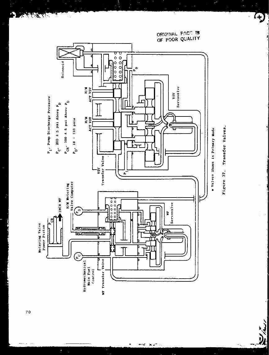
e.
t_
e.
70

-22V-
_F
[" ii_:....t
, + U
i
5 ',' Col
-22V
22 V Col.
SeIP"
r- o.._.,,.A
!I o_,.a _
F Amlay Dlr lv_r
_c k_ Selector
ri
tmmm)ammmmj -21 v --
,..,R:.:NAL PA_E i_OF POOR QUALITY
rll Dr _'.er i
I
%> r
I_ &ese:
!
- J +_e r,,,o_a lye _1" f:o_e i
Transfer
I - i
I 11 'III
°
, L;---_r-.
: 1_1'+_ ', i:_ :._i!::I2L.__:_L_J ___J___J ........
• w;tch
Figure 38. Fail-Safe and Backup Functions.
71
feature in the solenoid valve assures that the existing condition, either pri-
mary or secondary, is retained until a definite signal is received calling for
a mode change.
A selector switch in the control room sets the basic system operating
mode (Figure 38). With the selector in the normal position the system will
.ormally be in the primary mode, but it will _wi_ch to backup position if
(i) the digital control power supply voltage is low, (2) if the digital con-
trol self-test computation shows a fault, or (3) if a core rotor overspeed
occurs which sends a fuel pressure signal from the fuel control to an over-
speed pressure switch. Selector switch positions are also provided that set
manual mode only, primary mode only, or existing mode only operation.
10.2 SENSOR FAILURE PROTECTION
The E3 digital control system incorporates a number of electrical sen-
sor_ that are necessary for proper system and engine operation. Provisions
must be made to acco_odate occasional sensor failures without significant
operational effect. This could be done with sensor redundancy, but this adds
_ost, increases maintenance activity, and requires additional mounting pro-
visions on the engine. Instead, the computational capability of the digital
control is utilized to provide the equivalent of sensor redundancy without
multiple sensors by employing a failure indication and corrective action
(FICA) concept.
The basic FICA concept involves the incorporation of a simplified engine
model in the digital control software, a_ong with sensor failure detection
logic which monitors sensor signals and replaces failed signals with model-
generated substitutes. A mathematical filter technique (extended Kalman
filter) is used to continuously update the engine model using data from all
nonfailed sensors.
Figure 39 is a diagram of the FICA. The engine modeL, outlined in the
center of the diagram, is initialized with sensed in')uts. It then continues to
compute the state-cf-engine variables based on inputs fro_ (I) environmental
sensors, (2) the fuel control loop (fuel flow rate of change), and (3) the
model/sensor signal comparison through the update matrix. If any of the
72
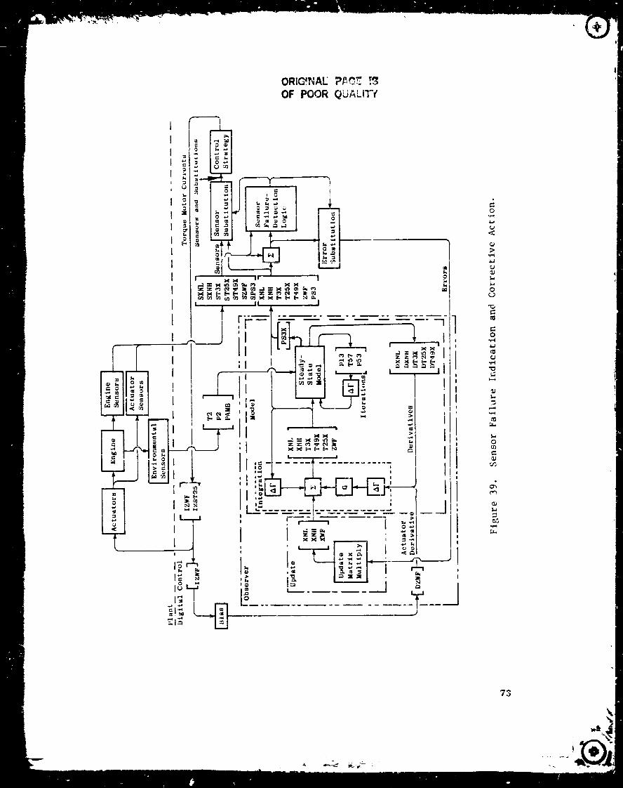
I
I
I
i
0
I •
I
I
II
I
0_
_I_I _
I I
! t
ol
I
ORIGfI_IA_ P_C_ _
OF POOR QUALIT7
,--_,.i O
!If
1I
i--i
M
al I
I
I
Ii
I
i'I
III
I
II
I!I
II
!
II
1
0
4-1
¢0
1.1
_J
0_._
0
_J
(J
_J
0
c_
_S
73
_._"

sensor signals deviate from the equivalent computed state variable by more
than a predetermined acceptable amount the computed value is substituted in
the control strategy. The error for that variable is eliminated from the
update process, and the model continues to :ompute all state variables with
suitable accuracy.
In the E3 demonstrator engine program the FICA concept will be demon-
str_ted on the ICLS engine. The core engine, which will have a less extensive
control system (no LPT-related control and slave controls for core stators),
will employ a simpler, out-of-limit strategy for sensor failure protection.
When any sensed input is beyond the normal operating range the digital control
will take the following action:
Core Speed
Core Inlet Temperature
Compressor Discharge
Tempe ra tur e
Compres sot Discharge
Pressure
Exhaust Gas Temperature
Casing Temperature
Start Bleed Position
Compres sot ClearanceValve Position
Turbine Clearance Valve
Pos it ion
Main Zone Shutoff Position
- Indicate self-test failure, switch to
backup mode
- S_bstitute value from manual T25 poten-
tiometer on operator panel
- Substitute value calculated from core
speed and inlet temperature
- Substitute value calculated from core
speed and ambient pressure (as indi-
cated by potent iometer)
- Substitute value calculated from core
speed and inlet temperature
- Set associated value at maximum clear-
ance position
- Set control output to zero, valves
close.
- Set control output to zero, valve goes
to maximum clearance position.
- Set control output to zero, valve goes
to maximum clearance position.
- Set control output to zero, valve
opens.
74

Fuel Metering Valve Position - Indicat= self-test failure, switch tobackup L)de.
Power Le'_er Position - Switch to backup mode.
l_ese out-of-limit functions will also be included in the !CLS control
system for use if the non-FICA mode is selected.
The E3 digital control also includes provisions for responding in a
safe manner to certain fuel valve position sensing failures that result in
large errors within the normal operating range. (Loss of certain electrical
connections to the fuel valve position transducer can cause such a failure.)
The control monitors rate of change of fuel valve position and, when it
detects a rate in excess of the normal maximum rate that persists long enough
to indicate it is not caused by random electrical noise, it switches to the
backup mode. in this way, it protects ag_ inst a sensor failure that could
cause an inadvertent and excessi _ rise in fuel flow.
75
1 I. 0 SYSTEM COMPONENTS
ll.l DIGITAL CONTROL
II.I.i General Description
'l_e E 3 digital control is a full authority digital electronic control
(FADEC) designed for operation of the integrated core/low spool (ICLS) con-
figuration of the E 3. It is engine mounted and air cooled. For normal
operation, electric power is provided By the engine-driven alternator. For
engine starting, and in the event of alternator failure, power is provided from
the airframe (test cell) 28-volt bus.
The control is housed in a rectangular chassis with four mounting feet,
one located at each corner, to support the chassis to the attaching points of
the engine frame. A two-sided cold plate separates the chassis into two com-
partments. _he multilayer ceramic modules are mounted on the cold plate in
the shallow compartments The discrete modules are mounted to the cold plate
in the deep compartment. Cooling air flows through the finned passage separa-
ting the two mounting sides of the cold plate. Electric interface with the
control is through seven wall-mounted electrical connectors. Two air pres-
sures are piped to the control and penetrate the chassis wall to the module
pressure sensors/transducers. Housed within the control chassis are 5 multi-
layer ceramic modules, 16 discrete potted modules, 1 relay, and 8 adjustment
potentiometers.
A partition wall in the deep compartment metallically shields the power
Jupply functions from the remainder of the control to eliminate electrical
noise interference. All wires between the compartments penetrate the shield
only through suitable EMI (electromagnetic interference) filters.
The digital control accepts inputs from inside and outside the control
system. The outputs control signals to the control system as a function of
control system strategy which is programmed into the control. Inputs and
outputs are shown on Figure 40.
76

Fuel Meterin_ Valve
I N_in Ions Shutoff Valve
Tmp, Core Inlet (]¢TD)
A. Position Demand
(Torque Motor Drivers)
| Other
b_TC V.lv. (.... ff) ]
Backup Selector J
----_ Pilot Zone Reset (on-of,)[
r_ E,citat_o. ]
Aircraft
Interface
Figure 40. Digital Control - Inputs and Outputs.
77

The simplified schematic (Figure 41) shows the input/output section, the
processor section, and the miscellaneous section. The input/output section
includes the 16-bit buffered data bus (BD-bus) as its data path to the central
processor. Digital information is passed from the inputs onto the BD-bus
through the tristate buffer to the data bus (D-bus). Digital information is
also passed from the D-bus through the tristate buffer onto the BD-bus and
into the output circuits. All data transmission is done under control of the
central processor and on a timesharing basis.
The processor section consists of an address bus (AD-bus) and a D-bus.
All data information into and out of the control will pass over the D-bus and
into the processor. And all destination information will pass over the AD-
bus and will determine the source or destination of data present on the D-bus.
The miscellaneous section contains a linear variable phase transducer
(LVPT) excitation driver, a crystal control clock oscillator, and an alternator-
driven power source with a 28-volt d.c. power source as a backup.
The digital control provides the computational capability for the selected
control system. All of the control law programs, signal conditioning, data
processing, and input/output capabilities needed to provide the desired engine
operation and interface with the sensors and act,ation components are included
in the control.
11.1.2 Microprocessor
The central processing unit (CPU) is based on an array of four 4-bit
microprocessors cascaded to handle the 16-bit word. This is a fully parallel
machine operating at 3.5 MHz clock rate. Figure 42 shows a simplified block
diagram of the 4-bit slice AMD 2901 microprocessor used in the control.
Features of this processor are (I) special purpose, (2) fractional, (3) two's
complement, 4 quadrant, (4) microprogrammed, (5) 3.5 MHz clJck rate, (6) 64K
word program memory addressing capability, (7) 512-word RAM size, (8) 64-
instruction repertoire, (D) 16-bit word size, and (I0) low-_Jwer Schottky
TTL logic family.
78
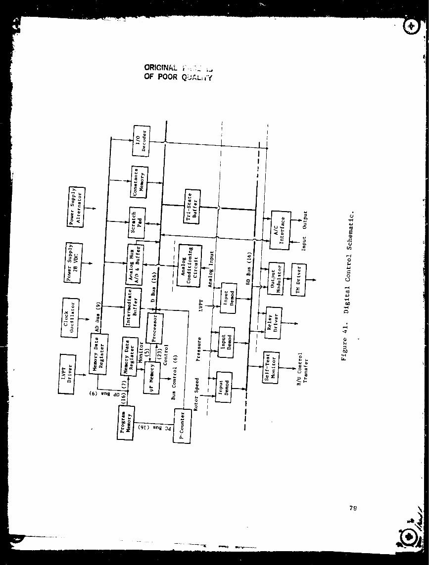
ORIGINAL _".._":.. _.," ip iOF POOR Qv_,,.iiY
_J
4_
qJ,.C:_J
P,I0
4_
OL}
4.J
...,?
IT.,
79

ORIGINAL PAGE IS
OF POOR QUALITY
(4) i
A SeZect RAU B Select16x4
Clock__
Nano-lnstructlons
Data In >
rol
ROM
352 Bits
vcc > (z)
i/o (4) I
_-_1 Bit , 1(3) I/0Shlf ter _-<_ >
(_ ](4)
(4)T _(4)
P
ALU "+4
ero Detect
erflolw
(4)_ (4) l (4)
Data Out
Figure 42. AMD 2901 Microprocessor Block Diagram.
8O

This processor is microprogrammable which enabled its design to be tai-
lored for this engine control application. Such tailoring makes it a special-
purpose machine. This 16-bit machine computes algorithms using fractional
arithmetic in two's complement notation and has 64 microinstructions which
include:
• Input, output, and an address strobe instruction
• Load instructions from various sources
• Add and substract instruction of different loc=tions
• A store instruction that places data in a specified location of
read/write memory
• A four-quadrant multiply and divide instruction
• Register exchange instructions
• Magnitude with limit instruction
• Various limited instructions to prevent data overflow
• Right- and left-shift instructions
• Selector instructions that select the most positive or negative
data from various sources
• Logical instructions including AND, OR, EXCLUSIVE OR, NOT, and
COMPLEMENT
• A number of jump instructions i_cluding jump to subroutine and
return.
Mnemonics are listed inThe instruction set functions microcycle information.
the Appendix.
11.1..3 Memory
11.1.3.1 General
Requirements for the digital control memory resulted in partitioning into
four memories: program memory, constants memory, scratch pad memory, and
microprocessor memory.
81
\
q
11.1.3.2 Program Memory
T_;e program memory uses programs_able read-only memory (PROM) integrated
circuits, and includes a list of instructions representing the control laws to
be executed by the processor. This control architecture and strategy software
is arranged in sequential order of execution. The program memory is located
in the multilayer ceramic module (MCM) HB8 (AI8 module) in the control. The
module includes 16K of memory capacity, although this E3 program is expected
to require no more than 8K of memory.
11.1.3.3 Constants Memory
The constants memory is a IK nonvolatile memory (PROM) that is maintained
separate from the program memory. It is used to store constant values used in
the control calculation. The constants memory is located in the discrete
module A9 and is mounted on a wire-wrapped circuit board so that values in the
constants memory can be changed without affecting the program memory.
11.1.3.4 Scractch Pad Memory
The scratch pad memory is used for temporary values during the calcula-
tion process as the program is executed; it is a 0.5K random access memory
(RAM) having read/write capability. Each location is available for input and
retrieval of data. This RAM is located in the: digital processor MCM HB6
(AI6 module).
11.1.3.5 Microprocessor Memory
The microprocessor memory is the repository for the processor instruction
set. This is a read-only memory (ROM), accessed by the microprocessor during
execution of the contrGl program. The ROM is located in the digital pro-
cessor module HB6 (AI6 module).
8_
11.1.4 Description of Module Functions
II.I.A.I General
Partitioning of the digital control circuitry for incorporation into the
on-engine control was done to utilize existing MCM's. Three of these MCM
designs are from the original Navy FADEC program. The_e are the AI4A, _I4B,
and AI5 modules. The other two MCM's (AI6 and AI_) were designed for the
F404-FIGI program and incorporate features aimed toward improved life and
reliability. Because the circuitry included in these MCM's fixe_, the rest
of the control circuitry was partitioned to adapt to these existing modules.
Functional descriptions of each module follows in sequence of the module
identifying number (Figure 43).
11.1.4.2 Module A7
This module includes the isolation transformers used for the 12 signal
lines from the aircraft interface simulator (AIS). There is a high, a low,
and a groundline for each of four signals: data, clock, transmit, and receive.
This metallically shielded module houses the coupling transformers for each of
the 12 signal lines.
11.1.4.3 Module A8
Module A8 houses the two pressure transducers and a temperature-sensing
integrated circuit. These are digital-type sensors in which force is applied
to a quartz cr_stal proportional to sensed air pressure. The resonant fre-
quency of the quartz crystal is proportional to the applied force and to the
sensor temperature. The output signal from the pressure sensor is the crystal
resonant frequency. The temperature-se_sing integrated circuit provides an
output voltage proportional to pressure sensor temperature. Control program
software includes equations to modify the sensed pressure signal as a func-
tion of the pressure sensor temperature.
83

ORIGII'_AL PAint titOF POOR QUALITY
84
v
I
=
J
I
o
o
0L_
,-4
I-
I

11.1.4.4 Module A9
This is a digital discrete module which contains the constants memory.
It consists of one wire wrap circuit board with four PROM dual inline packages
(DIPS) mounted to it. This module is mounted on the cold plate in the shallow
compartment of the control. The address bus is input tc the constants memory
and data is output to the buffered data bus. This memory can be changed with-
out affecting the program memory.
11.1.4.5 Modules AI4A and AI4B
These are two identical multilayer ceramic modules identified also as
HB4A and HB4B. The modules incorporate the control input/output functions.
The channel assignments have been made for use of the several channels on
each module and the use of more than one module, and the system software is
written to match the channels as wired. Each of the modules includes the
following functions:
i ° One engine speed decoder circuit comprising a zero crossing detec-
tor, counters, and latches to measure the time between the zero
crossings of the input signal and enters that time on the buffered
data bus.
. Four torque motor drivers that are power amplifier_ operati_Lg in
response to the output modulator. This is used to connect digital
outputs from the central process into demand torque motor currents.
The torque motor current is established by the length of the "on"
time of the driver amplifier. These four channels of torque motor
drivers are identic_l hardware and can be used to operate any of
the control loops. The channel assignments have been made and the
software is created to match for proper system control. By supply--
ing either tlO-volt d.c. or only +10-volt d.c to the driver
circuits, the driver can be used for either the "fail-safe" ser_-o-
valve (in the fuel valve control) or for the "standard" servovalve
(in the air valve controls).
3. Four position d@coder circuits comprising a zero crossing detector,
counters, and latches to measure a phase difference from the linear
variable phase transformer (LVPT) and to input the digital value on
the buffered data bus. The phase difference is proportional to the
position of the controlled variable as measured by the LVFT.
e Two pressure decoder circuits comprising counters and latches to
measure the frequency output from the pressure transducer and to
input the digital value onto the buffered data bus.
85
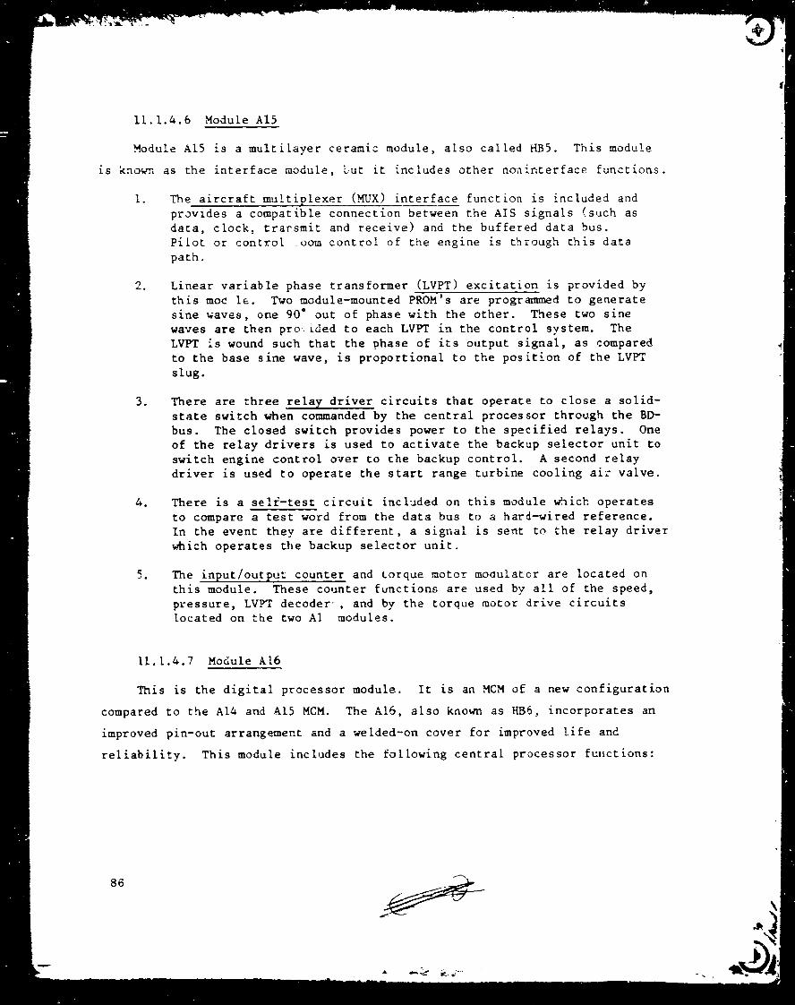
11.1.4.6 Module AI5
Module AI5 is a multilayer cerami= module, also called HBS. This module
is known as the interface module, Gut it includes other noninterface functions.
I. The aircraft multiplexer (MUX) interface function is included and
provides a compatible connection between the AIS signals (such as
data, clock, trarsmit and receive) and the buffered data bus.
Pilot or control _oom control of the engine is through this data
path.
. Linear variable phase transformer (LVPT) excitation is provided by
this moc le. Two module-mounted PROM's are programmed to generate
sine waves, one 90 ° out of phase with the other. These two sine
waves are then pro _ded to each LVPT in the control system. The
LVPT is wound such that the phase of its output signal, as compared
to the base sine wave, is proportional to the position of the LVPT
slug.
. There are three relay driver circuits that operate to close a solid-
state switch when commanded by the central processor through the BD-
bus. The closed switch provides power to the specified relays. One
of the relay drivers is used to activate the backup selector unit to
switch engine control over to the backup control. A second relay
driver is used to operate the start range turbine cooling air valve.
o There is a se!f-tes= circuit included on this module _ich operates
to compare a test word from the data bus to a hard-wired reference.
In the event they are different, a signal is sent to the relay driver
which operates the backup selector unit.
. The input/output counter and torque motor mo0ulator are located on
this module. These counter functions are used by all of the speed,
pressure, LVPT decoder _, and by the torque motor drive circuits
located on the two A] modules.
11.1.4.7 Module AI6
This is the digital processor module. It is an MCM of a new configuration
compared to the AI4 and AI5 MCM. The AI6, also known as HB6, incorporates an
improved pin-out arrangement and a welded-on cover for improved life and
reliability. This module includes the following central processor functions:
86

A microprocessor comprising four 4-bit-slice integrated circuits
cascaded to provide a 16-bit machine. he A_ 2901 is used.
A microprocessor memor[ that holds the system instru, set.
The clock frequency divider and distribution is provided by thismodule.
The :_and0m access memory (RAM) is incorporated to provide the
scratch pad memory used during program execution.
The p.5o_ram counter (P-counter) is included in thLs module and is
used to walk the system through the program memory locations during
the execution of the program.
A tristate buffer is included to interface the data bus off this
module for connection to other modules.
11.1.4.8 Module AI8
This is an MCM similar in configuration =o Lh= AI6 module, The AI8 (HB8)
incorporates the program memory in PROM chips, size IK by 8. There are 32
PROM's arranged to give 16K of 16-bit words. This program memory interfaces
with the A16 module through the P-counter and the operation code busses.
11.1.4.9 Module A2(,
Module A20 is a conventional printed circuit board, a potted module that
includes circuitry to provide the regulated 15-volt power used throughout the
control. A zener diode provides the reference and an op-amp operates _hcough
staged transistors to hold the output voltage proportionalto the reference.
This provides the regulated +15 volts. The -15 volts is controlled similarly,
except that the op-_mp tracks the +15 volts rather than the zener reference.
The input to this regulator is ±22 volts.
11.1.4.10 Module A21
This is a discrete module that includes circuitry to provide for the fine
regulation of the 5-volt power supply. Input to this module is from the engine-
87

driven alternator as coarse-regulated and rectified by a separately packaged
(outside the control) transformer, choke, and diodes. A compatible alternator
would negate the nee_ for this separate coarse regulation.
Input to the A21 module is at approximately 9-voits d.c. The moduleincludes the following functions:
lo Primary switching shunt transistor, controlled by the primary con-
trol circuit in module A22 to hold 5 volt_.
. Backup switching shunt transistor, which is controlled by the backupcontrol circuit in module A22 to hold 5.2 volt3 in the event the
primary regulation circuit fails in the direction of high voltage.
. A filter circuit comprising 2 chokes and 16 capacitors to smooth
the regulated 5 volts for use by the digital circuits.
. Diodes to permit connection of the alternator-supplied regulated 5
volts and the 28-volt-d.c.-supplied reguiated 5 volts, such that
loss of alternator supply allows automatic takecver by the 28-volt
system.
11.1.4.11 Module A22
This module is a conventional printed circuit board discrete module which
includes the control circuitry for the A21 switching shunt 5-volt regulator.
An integrated circuit device contains the 5-volt reference and controls a low-
power transistor, which in turn controls the shunt transistor (in A21 module)
to hold the regulated voltage proportional to the reference. As discussed in
the preceding section, there are two such circuits: one to regulate at 5 volts
and one to regulate at 5.2 volts.
11.1.4.12 Module A23
This is a discrete module that includes circuitry to provide for the
regulation of the ±3 volts and 22 volts d.c. Input to this module is fro_
the engine-driven alternator using a different set of windings than that used
for the module A21. The module includes the following function_:
A _ag-amp regulator is used to control the output voltages of the
tapped transformer. This is done by using a feedback winding on
the power transformer in order to provide control current to the
mag-amp.
88

There are 8 diodes arranged to give full wave rectification of the
±13- and 22-volt output from the power transformer. There are 12
capacitors arranged to provide suitable smoothing and filtering of
these voltage outputs.
An additional winding on the secondary of the power transformer
provides the signal used by the control for core rpm measurement.
11.1.4.13 Module A24
Module A24, a discrete module, includes two printed circuit boards com-
prising the circuitry used to control the dc-dc converter and the pulse width
regulator. Circuits residing iI_ module A24 provide the following functions:
le The dc-dc converter contr_l circuit includes an integrated circuit
oscillator; its output operates two stages of control transistors.
Output of the control transistors is used to operate the power
switching transistors in module A25 to convert t e input 28-volt
d.c. to s.c. for input to its power transformer.
. The pulse width regulator control circuit includes an integrated
circuit oscillator whose output operates two stages of control
transistors. Output of the control transistors is used to operate
the power switching transistors in module A25. This control circuit
senses the fine volt bus voltage and operates to control the "on"
time of the power transistors to regulate at slightly less than5 volts.
11.1.4.14 Module A25
This discrete module includes the transformers and power transistors used
to provide regulated 13 and 22 volts d.c. and regulated 5 volts d.c. when
supplied with 28 volts d.c. The power transistors are controlled by the
circuitry included in module A24 and described above. The following functions
are included:
The dc-dc converter circuit includes the poh_r transformer with
tapped secondaries to provide the 13 and 22 volts. These feed
through the eight diodes arranged to give full wave rectification of
the ±13 and 22 volt outputs from the power transformer. The 28-
volt d.c. input is converted to alternating current by the cycling
power transistors and is then input to the primary winding of the
power transformer.

fi
The pulse width regulator circuit includes the power transformer
with a tapped secondary to provide 5-volt output. The 2S-volt d.c.
input is converted to alternating current by the cycling power
transistors and next input to the primary winding of the power trans-
fcrmer. The fine regulation of 5 volts is accomplished by varying
the "on" time of the power transistors.
11.1.4.15 Module A26
A26 is a discrete module that includes two printed circuit boards incor-
porating circuitry to receive d.c. signal level voltages onto the M_'X, con-
vert these voltages to a digital word, and place the digital word onto the
buffered data bus. The loll -ing functions are included:
I. Two 16-channel _KJX's and associated control functions are included.
The FADEC address bus operates through the _ control to sequen-
tially select the channel to be output from the _ through a
buffer amplifier and input to the A-D converter.
. The A-D converter, its control functions, _nd its precision voltage
reference are included_ When an analog voltage output from the _
is input to the &-D converter, the control function initiates "start
convert" after sufficient time has elapsed for the signal voltage
to stabilize at itg final value. _e converted digital _ord is then
output to the tristate buffer and, when signaled, is placed on the
BD-bus.
. The precislon voltage reference included in t_s module for the A-D
converter is used as input to buffer amplifier circuitry, located
in module A30, to generate the ±lO-volt reference voltages for use
throughout the comtrol.
11.1.4.16 Modules A27_ A28_ and. A29
The three modules are identizal except for calibration. Each is a dis-
crete module including two identical printed circuit boards. Each printed cir-
cuit board inc]udes circuitry for one thermocouple amplification function.
The three modules, therefore, include a total of six thermocouple circuits.
Each thermocouple amplifier circuit comprises the following:
. Cold junction compensation is provided by the "gumdrop", a balco
wire-wound coil that has resistance in proportion to the tempera-
ture and the chromel-alumel junction physically adjacent to the
coil. This varying resistance provides a calibrated bus to the
the_couples input to the Stage I amplifier.
9O

Two stages of amplification are provided so that the output from
the circuit is a 0 to -I0 volts d.c. signal proportional to the
thermocouple-measured temperature. This output signal voltage
from each printed circuit board of each module is input to the
specified channels of the MUX's located in module A26. From there
it is transmitted to the BD-bus.
11.1.4.17 Module A30
This is a discrete module comprising two printed circuit bc_rds: one
includes six amplifier circuits, the second board includes six amplifiers.
The function of each is listed below.
I. There are five gain-of-one isolation amplifiers. Each can ac=ept a
0 to lO-volt d.c. input and provides an isolated output of 0 to
-I0 volts d.c. These signals are next input to the designated MID[
channels described in Section 11.1.4.15 and then on to the Bl>-bus as
a digital value.
e There is a pressure transducer temperature (PTT) amplifier that
monitors the output of the AD 590 temperature sensor chip located
in the pressure transducer module (module A8). Output of this
amplifier also is a 0 to -I0 volts d.c. proportional to the tempera-
ture in the A8 module. This voltage is input to the specified MUX
channel.
. There are two resistance temperature detector (RTD) amplifiers that
monitor the resistance change of the two RTD sensors, one located at
the fan inlet and one at the core inlet. Output of these are 0 to
-I0 volts d.c. proportional to the resistance change of the RTD which
is proportional to the two sensed temperatures. This voltage is
input to the specified MUX channel.
. There are two RTD excitation circuits which provide the constant
current excitation to the two RTD's.
o There are two gain-of-one amplifiers. One is used to generate the
plus and one the minus 10-volt d.c. references used throughout the
control. Input to these amplifier circuits is -10 volts d.c. from
the precision reference chip located in module A26.
11.1.4.18 Module A31
Module A31 is a discrete module that includes two printed circuit boards.
Included are several miscellaneous analog circuits, as follows:
I, The LVPT excitation resistors are included in this module. For each
LVPT, each of the excitation signals passes through one of the 400-ohm resistors. The module incudes 20 such resistors, but the E 3
control uses only 14.
91

The power "on" detector circuit and the relay controlled by this
circuit are incl,Jded. In the event that the 5-olt power is not
in regulation, such as during sta_t_p without the 2_-volt supply
or a complete power loss during operatien_ the fo.towing actionsoccur:
Short the main fuel valve torau_ _ao or driver output to give a
zero out_,ut signal (close fuel ,a!ve).
Short the main zone shutoff vai_e torque motor driver output to
give a zero output signal (open MZEO valve).
• Reset the program counter to zero.
Reenergize the coil of the relays for the backup selector unit
and the start range turbine cooling valve. This results in e
switch to backup control and closing the S" air valve.
There are two LVPT amplifiers included; each provides amplification
of an LV_ output signal in order to be compatible with the zero
crossing detector. The control system includes two short LVPT's
which have output signal levels too low and, therefore, must be ampli-fied.
There are two speed circuit ar.plifiers which are used to make steeper
slope signals at the zero crossing to assure compatibility with the
zero crossin_ detectors. The core speed and the fan speed signals
each use one amplifier.
11.1.4.19 Module A32
This module is a discrete module including one printed circuit board.
The clock oscillator and the iteration control circuitry are included in this
module.
11.1.5 Physical Confisuration
11.1.5.1 General
The digital control circuitry was partitioned as shown in Figure 43
and as described in the preceding paragraphs. This partitioning was based on
using available MCM's. Three of tl,e MCM's were developed under the Navy
FADEC program during 1978-1980. Two newer MCM's are currently being devel-
oped for a military engine-mounted electronic control unit. The remaining
92

circuitry, which is not included on the five MCM's, was partitioned in a logi-
cal functional arrangement as follows:
Function
Power Supply
Pressure Transducers
Isolation Transformers
Clock Oscillator, Iteration Control
Con3tants Memory
Analog-to-Digital
l'hermocouple Amplifier
LVPT Excite and Amplifier
Isolation amps and RTD Excite
6
I
I
I
1
1
3
1
1
Total 16
11.1.5.2 Chassis Design
The chassis design is shown in Figures 44 and 45. The final design uses
a two-sided air-cooled cold plate separating the box into tw9 compartments:
one for the MCM, one for the discrete modules. The cooling air flowpath is
through a single layer of fin stock arranged for flow across the width of the
box instead of along the length. This gives a larger flow area and a shorter
flow distance. Provisions are included for wiring across the cold plate
assembly.
The cold plate assembly includes two plates separated by the fin stock
airflow passage. The plates are thick enough to accommodate the many threaded
inserts required for the device holddown screws. All of the modules and
devices are attached to the plates by means of these holddown screws. And
all of the modules and devices can be installed or removed by fasteners on
their mounting side of the respective cold plates. These thick plates provide
a flat mounting surface for the modules to assure maximum heat transfer. The
thicker plates also provide improved flatness to assure nearly 100% fin stock
93
_ _ .'f'---*9
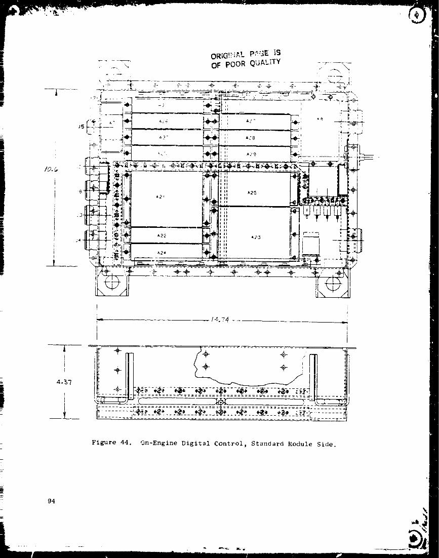
4._-_
1_
! i
_- / 4.74 ,,-4I JI
-- - ....................... "-" - - :"- -- - - .................. _--_ .... T-'
Figure 44. On-Engine Digital Control, Standard Module Side.
94
[] mm
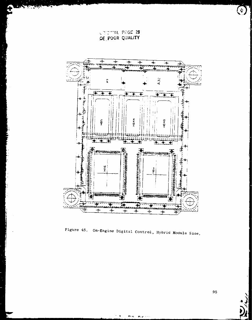
-, ..... .",t P,',G.: IS
OE POOR Q'JALITY
Figure 45. On-Engine Digital Control, Hybrid Module Side.
95

_F POORQCALITY
braze attachment to the plates. The circuit partitioning was completed, giving
consideration to the discrete module size. This chosen arrangement resulted
in all of the discrete modules having two common dimensions (except the pres-
sure transducer and the isolation transformer modules). All cf the discrete
module housings are the same height, the same length, and of identical con-
struction. Only the width is larger for the power supply module hoosings in
order to contain larger devices such as transformers, chokes, filter capaci-
tors, and diodes. This similarity of module housing _ize provided significant
design cost savings, not only in the housing design but particularly i_ the
many printed circuit board designs.
11.2 ALTERNATOR
The control alternator provides electric power to the digital control
and a core signal for the cockpit or test cell readout. This is an FI01
control alternator. The alternator is engine-gearbox mounted and driven
with the rotor attached to the gearbox output shaft. Figure 46 shows the
electrical schematic and cross sections of the unit. For this _pplication,
three of the four windings are used.
The design characteristics of the control alternator are listed below.
• Configuration
• Drive
• Output frequency
Four windings
Six pole pairs
Permanent magnet type
25002 rpm at takeoff power
0.1 times drive rpm
9B
Output Power
Winding % N Volts Amps
B
C
15
85
115
15
I00
115
I0
I00
115
24.3-39.8
26.8
0-308
10.4-16.3
69.4
0-122
5.78
57.8-74.7
0-86
0.72-0
1.3
1.81-0
3.0-0
3.0
6.35-0
0.002
0.02-0
6.18-0

Speed Signal
5 volt Power Supply
.°_._
O:: ,-3g.-. :.... :_'
_-- I'!e!'!sis!7)[_!,0!_{,,i,_,LjU'' L.LJWDG '.vDG wDG WDG
9 C _t A
' J [ I L-.-.- Not Used- 13, 15, 22 volt
Power Supply
Electrical Schematic
II 12
3 I0 24
/ I"_.=' =iE:L-I/ Ik\-',------'_G"_tc _iII
/ \ \ \,, s,_U.TS-_, I/ I _.OO
\ \'_.20nOT /OT _ C 5
\\_P;, _- _-_/
76
Figure 46. Co_%trol Alternator.
97

11.3 SERVOVALVES
Figure 47 shows a schematic of a "fail fixed" electrohvdraulic _ervo-
valve. This is typical of the servovalves used in control of three of the
enBine functions; that is, main fuel flow, core stator control, _:nd main zone
shutoff. The remaining eontrolied functions, such as pilot zore reset,
start bleed control, and three clearance control loops, use the "standard"
type e!ectrohydraulic se'vovalves, the principal difference between the two
types of servovaives is in the characteristics of the flo,," versus milliamp
input relationship. These servovalves include a torque-motor-_perated jet
pipe first stage and a spool valve second stage.
For the "fail fixed" servovalve, the input current is_ between zero and
i00 milliamps and output flow is as follows=
• Up to 8 mA _ Zero output flow
• Between 8 and 50 mA _ Flow from CI port
• Between 50 and 92 mA = Flow from C2 port
• Above 92 mA - Zero output flow
For the "standard" servovalve, the input current is between -80 and
+80 mA and output flow is as follows=
• From -80 to 0 mA = Flow from C2 port
• At zero mA _ Zero output flow
• From 0 co +80 mA = Flow from CI port
The design characteristics of the electrohydraulic servovalves are listed
in the following:
98

Feedba
Spring
Armature-_. I
Isolation Tube__I
i
IReceiver
Elec_rica _ Leacs
First Stage Jet Pipe
or Jet Deflector
Stage
Spool Valve
Figru_-e 47. Typical Electrohydraulic Servovalve.
ii ii
99
I,

Number of coils
Connectio,
Ra_ee current
Maximum current
Resistance, d.c.
Coil matching,
d.c. resistance
Resistance, a.c.
Apparent inductance
Input wave shape
Input frequency
Variation
Fail-Safe
2
Parallel aiding
I00 mA
200 mA total
110 _k either coil
15 ohms per coil
Within 10% of other
Staed_rd
2
Parallel aiding
+80, -80 m_
220 mA total
II0 mA either coil
29 ohms per coil
Within 10% of other
300 ohms max
180 H]_z pos max.
40 H_z neg max.
Unipolar square wave
427 Hz
Pulse width modulation
300 ohms max.
180 _Hz pos max.
40 M}Iz neg max.
Unipolar square warp
427 Hz
Pulse width modulation
11.4 POSITION TRANSDUCERS
11.4.1 Linear Variable Phase Transformer (LVPT)
Figures 48 and 49 show examples of two of the LVPT's used for the E3
control system. The LVPT produces an output voltage _hose phase changes
proportionally with t,.e position of the core. The transformer utilizes four
primary coils whi:h are wired in alternately connected, out-of-phase pairs.
The two pairs of primaries are connected to a two-phase, 427--Hz source having
90 ° of phase separation. The four coil sections then represent phases of 0 °,
90 °, 180 ° , and 270 ° . A moveable core positioned along the axis of the traz;s-
former will couple the flux of several primary coils int_ the secondary coil
where the flux vectors are summed to produce an output voltage whose phase
lags with respect to the reference (0 degrees). The masnitude of the phase
lag is proportional to the position of the core with respect to the primary
windings.
i00

\)
\)
d
i
I
////
CR:C ':'_ _" T.': "L- !$
OF £OCR Q JALtTY
,'4
o
r.tj
I:I
o
o
om
o
m
o

J
Il
Ir
i
I
C_""' -- " .....(_ r_'j_
0
0
t_
0
0
0
0m
e.,
O
IO_

There are three different lengths of LVPT's used in this system. Each
is constructed to give a linear output of 9 ° to 171" phase difference between
the output signal and the reference for full stroke.
11.4.2 Rotary Variable Phase Transformer (RVPT)
Figure 50 shows the RVPT as used to sense the position of the fuel
metering v_Ive located in the fuel control. The RVPT is electrically identi-
cal to the LVPT. The coils are arranged to be responsive to the rotation of
the core. The output is linear betwee_ 9 ° and 171 ° phase difference b, _ween
the utput signal and the reference for full rotary stroke.
11.5 FAN SPEED SENSOR
An FI01 engine fan speed sensor is used on the E 3. The sen_or utilizes
a self-powered magnetic sensing head consisting of two separate but tandem
sensing coils. The two coils provide fan speed signals separ;tely to the
engine digital control and to the off-engine (test cell) speed indication.
The fan speed sensor is installed sc the sensing head is positioned within
minimum practical clearance =r_n the toothed target wheel mounted to the fan
shaft. The toothed disk has six identical, equally spaced teeth.
11.6 FAN INLET TEMPERATURE (TI2) SENSOR
Tb_ inlet temperature sensor, Figure 51, measures the freestream air
temperature entering the engine. The active element is a small coil of
piatinum wire which changes electrically as its temperature changes. This
resistance temperature detector is mounted on and protrudes through the
inlet duct ahead of the fan. The sensor housing is a slotted a:rfoil with a
series of small holes. The action of the airfoil, slots, and holes results
in air flowing around the sensor at essentially freestream temperature unaf-
fected by boundary layer conditions. This is the same _ensor as used on the
FI01 engine to sense T2.
The design characteristics of of the TI2 sensor are listed as follows:
103

rh
"0
.J
0
0 C_
0
\
L
_w 0
{J ¢._
I._ 0
0
0_D
i
_J.a
00
0
.w
0(:w
cJ
b_
u'}
b_.ew
i04

Air Flow.
I
Figure 51. Fan/Compressor Inlet Temperature
TI2/T25 Sensor.
105

Range
Excitation
Output
Static accuracy
Response
Recovery error
219 to 345 K (-65 ° to 160 ° F)
Constant 12.5 mA d.c.
Resistance proportional to temperature
0.3% absolute temperature
6 sec at 4.5 kg/s/m 2 (10 Ib/s/ft 2)
0.5% absolute at 0.4 Mach
ii.7 COMPRESSOR INLET TEMPERATURE (T25) SENSOR
The compressor inlet temperature sensor is a resistance temperature
detector and is the same part number part as the TI2 sensor. This T25 sensor
is located in the core compressor inlet duct and operates over a range of
219 to 403K (-60" to 265" F).
11.8 COMPRESSOR DISCHARGE TEMPERATURE (T3) SENSOR
The T3 sensing probe assembly is mounted on the outer combustor casing.
This is a chromel-alumel thevmocouple similar to a test instrumentation
thermocouple probe used on several previous engines. A leadout attachment
concept Zs incorporated te make the probe less susceptible to haedling damage.
The swaged magnesium-oxide-filled metal _heath in which the the_mcouples
junction is encase_, is led out, looped and spliced into a flexii,_e, metal-
covered lead before clamping to the probe housing. Figure 52 shows this 73
sensing probe design.
l'he design characteristics of the T3 probe are listed as follows:
Range
Output
Static accuracy
Response
Insulation
255 to 1089 K (0 ° to 1500 ° F)
Per MiI-W-5846C
0.75%
2.13 sec at 4.5 kg/s/m 2 (I0 Ib/s/ft 2)
0.85 sec at 27.2 kg/s/m 2 (b0 Ib/s/ft 2)
5 megaohm min. to ground
11.9 TURBINE DISCRARGE (T42) TEMPERATURE SENSOR
HP turbine discharge temperature is sensed by selected chromel-alumel
the_rmocouples in instrumentation rakes immediately behind the HP turbine.
Three thermocouple signals from the test instrumentation rakes are connected
106
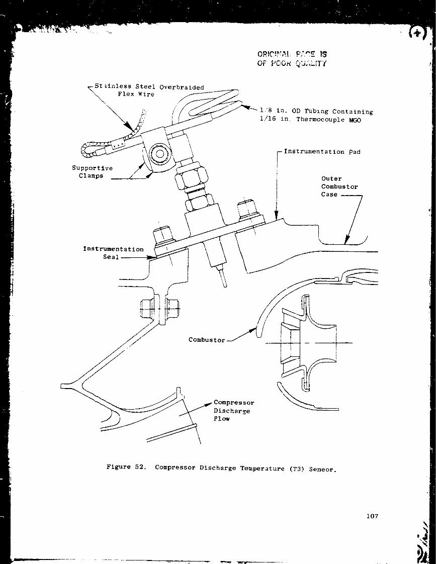
t_inless Steel Overbralded
Flex Wire/
;./1,'8 in. 0D Tubing Containing
1/16 in, Thermocouple MGO
Supportive
Clamps
Instrumentation Pad
Outer
Combustor
Case _j
\
k_
InStrs::it a.tion
Figure 52. Compressor Discharge Temperature (T3) Seneor.
107
in parallel and spliced into the control system electric cabling. These three
signals are from different radial and circumferential locations and are
dedicated to use by the contrcl system.
The design characteristics of the T42 thermocouples are listed as:
Range
Output
Static accuracy
Response
478 to i589 K (400 ° to 2400 ° F)
per MiI-W-584DC
0.75%
4.2 sec at 4.5 kg/s/m 2 (I0 ib/s/ft 2)
1.28 sec at 27.2 kg/s/m 2 (60 Ib/s/ft 2)
ii. I0 CASING TEMPERATURE SENSORS
For sensing casing temperature, chromel-alumel skin themmocouples are
mounted on each of the engine casings being used for clearance control (aft
compressor, HP turbine, and LP turbine) for dedicated use of the control
system. Three _hromel-alumel thermocouples are provided at each location:
one for initial _se and two for spares. Each of the thermocouples will be
spliced into a wiring junction to which the control cabling is attached.
II. II FUEL CONIROL
This is an FIOI control modified to be compatible with the E 3 digital
control and to provide for backup control. Figure 53 is a photograph of the
conrol.
Ii.ii.I Control Inputs
The following signals are input to the fuel control:
• Inlet fuel = Discharge flow from fuel pump
• T25 z Fuel pressure differential generated by control and remote
sensor
• PS3 = Air pressure signal
• N2 = Input shaft through f_el pump mounting pad
• PLA z Shaft rotation of 130 °
108
. .k

0,: _-" _"_'_ ,__',_ Qs, Lcf"¢
Figure 53. Main Fuel Control.
109

Q
O
Stator Feedback = Linear motion of a flexible cable
Electrical fuel control signal = An electric signal from the
digital control
Position transducer excitation = Two sinusoidal signals
Transfer signal = A fuel pressure from the transfer valve
11.11.2 6ontrol Outputs
Engine fuel = Fuel to the combustor
StaEor actuation flow = Fuel supplied to external ports for actuation
Bypass fuel = Fuel returned to pump isterstage
Overspeed pressure = Fuel supplied for the overspeed pressure s_itch
Transfer supply - Fuel supplied for operation of transfer valve
External servo supply = Fuel supplied for remote servovalves
Metering valve position signal = An electric signal to the digital
control.
11.11.3 Mountin_
The control is mounted on the engine fuel pump which is mou_ted on the
accessory gearbox.
11.11.4 Control of Fuel Flow Primary Mode
In the primary mode, fuel flow to the engine combustor [s controlled in
response to the electrical fuel control signal from the digital control in
accordance with the servovalve characteristics.
11.11.5 Control of Fuel Flow Backup Mode
In the backup mode, fuel flow to the engine combustor is controlled in
accordance with N2 (core rpm) governing requirements with various overrides
as follows:
ii0

i °
.
.
N2 Governin$ - N2 is governed in accordance with the schedule per-
cent N2 versus PLA. The maximum speed flat on the schedule is
adjustable ±3%. The governor is of the preportional-plus-integral type_
Acceleration Limit - Except as limited by the absolute minimum,
fuel flow will not exceed the level defined by the accelerationschedule.
Deceleration Limit - Except as limited by the absolute minimum, fuel
flow will not be less than the level defined by the decelerationschedule.
Absolute Minimum Fuel Flow Limit - Set at 90.7 kg/h (200 ib/h) and
is internally adjustable between 45.4 and 181.4 kg/h (I00 and 400ib/h).
11.11.6 Overspeed Signal
An external fuel pressure signal is provided which operates a remote
pressure switch to cause automatic transfer to the backup control mode if core
speed goes above 13,450 (_70) rpm.
11.11.7 Ultimate Overspeed Limit
if core rpm exceeds 13,750 (±70), fuel flow will be cut off within 0.05
seconds and will remain so until control inlet pressure is below the normal
minimum as set by the pressurizing valve.
11.11.8 Stator Control
The control includes a feur-way valve to control flow to and from the
stator actuators through the transfer valve. The high pressure supply to the
stator valve is pump discharge fiow filtered within the control. The stator
valve low pressure return is to bypass return pressure.
Ii.]!,9 Operating Mode Transfer
The fuel control selects between primary and backup mode_ in response to
a fuel pressure signal supplied at the transfer signal port.
iii

Ii. Ii.i0 Pressurizing Valve
The control includes a pressurizing valve to maintain sufficient inlet
pressure for proper control and servovalve operation.
Ii. Ii. Ii Cutoff Valve
The control includes a valve to cut off the fuel flow and activate the
pump unload when PVA is below 2 °
11.11.12 Pump Unlo_.d
The bypass valve includes provisions for limiting inlet-to-bypass dif-
ferential pressure to 1758.0 kPa (255 psi) with the cutoff valve closed.
11.11.13 T25 Sensing
The control senses T25 by supplying fuel throug_ a fixed orifice to a
remote sensor that throttles the fuel and returns it at a differential
pressure proportional to temperature.
11.11.14 Meterin$ Valve Position Sisnal
The control provides an external electrical signal indicating fuel meter-
ing valve position.
11.Ii.15 Transfer Supply
An external port provides servo fuel to the remote transfer valve.
11.11.16 External Servo Supply
An external port provides servo fuel to the air valve actuation servo-
valves.
11.11.17 Control Pressure Drop
Pressure drop from inlet to outlet is less than 1241 kPa (180 psi) with
5897 kg/h (13,000 pph) flow.
112

11.11.18 Desisn Pressure Levels
The control is designed for inl =___and 0utle #_ pressure of _,'' 5 ]_._kPa fi6--'
psig) and a bypass pressure of 1172 kPa _170 psig).
11.11.19 P_ TorQue
Torque required to operate the PLA is less than 25 Ib-inches and there is
no self-motoring.
II.LI.20 Stator Feedback Loadin$
The control provides a 44.48 N (10-1b) force to keep the external cable
in tension.
11.11.21 Internal Adjustments
The control includes internal adjustments for absolute minimum fuel f'ow
and for maximum core speed.
Ii.ii.22 E__xt__£ernalAJj_s_ments
Provisions are included for internal adjustment of core idle rpm and for
fuel specific gravity.
11,i.2 HYDROMEC}tANICAL T25 SENSOR
The hydromechanical T25 sen_or is mounted in the engine airflow path
behind the fan and operates in conjunction with the fuel control to generate
a fuel pressure proportional to se_sed air temperature. This is an FI01
component. A gas-filled coil senses temperature which expands a bellows
inside the sensor body. The bellows applies a force to a beam balance system
which changes a flow area, thereby changing the pressure di ferential.
11.13 T_%NSFER VALVE
A two-position transfe,_ valve function is used t _ select between the
primary and the backup control modes of operation Because of the physical
installation limitations, the transfer valve function was partitic, ned into
113

two separate components identified as the statcr transfer valve and the fuel
transfer valve. Figure 37 is a schematic of the valves, Figure 54 is a drdw-
ing of the fuel flow transfer valve, and Figure 55 is a photograph of the sta-
tot _ransfer valve.
II.i3.1 Stator Transfer Valve
This component assembly includes:
• Multiland spool transfer valve
• Latching servovalve
• Spool valve position switch
• Stator system electrohydraulic servovalve
The spool valve is spring-loaded to the primary mode position. In this
position the fuel flow to the stator actuation system is provided by the
electrohylraulic servovalve as controlled by the digital control. When the
latching _._ovalve is energized to call for backup control, the spool valve
moves to _ ,e backup position such that fuel flow to the stator actuation
system is then provided by the hydromechanical fuel control. In the backup
position the electric switch is closed.
11.13.2 Fuel Transfer Valve
This component assembly includes the multiland spool transfer valve and
the fuel electrohydrau!ic servovalve.
The spool valve is spring-loaded to the primary mode position. In this
position the fuel flow to the fuel metering valve actuation piston is provided
by the electrohydraulic s_rvovalve controlled by the digital control. When
the latching servovalve on the stator transfer valve is energized to call f)r
backup control, the spool valve moves to the backup position so that fuel flow
to the fuel metering valve actuation piston is provided by the hydromechani-
cal contrcl. This fuel transfer valve assembly is mounted on and is flange
ported to the hydromechanical fuel control. Figure 53 shows the valve assem-
bled on the fuel control (lower right side).
114

f
I I i
Pc Supply
for Starer
Transfer
Valve Pv Mode
Signal from
Var. Stator
Transfer
Valve
Pc Regulated
Serve Pressure
Backup Control SignalOutput to Fuel
Control Metering Valve
Figure 54. Fuel Flo_ Transfer Valve.
115

ORIGINAL PAGE ISOF POOR QUALITY
Fail-Safe Servovalve
High Pressure
Fuel Inlet
Stator
Actuation
Ports
Latching
Servovalve
Primary/
Backuc Mode
SensingSwitches
Low Pressure
Fuel Retu_.1
Backup Stator
Actuation Inputs
Figure 55. Stator Transfer Valve.

ii.14 OVERSFEED PRESSURE SWITCH
This is a differential fuel pressure switch that is used to provide
switching logic for backup mode selection in response to an overspeed fuel
pressure signal from the hydromechanicl fuel control. Figure 56 shows an
outline drawing and a schematic.
Design characteristics of the pressure switch are as follows:
• Switches in the "normal" position for 0 to 448 kPa (0 to 65 psi)
differential pres3ure
• Switches in the "opposite to normal" position for above 7826 kPa
(135 psi) differential pressure
• Switches rsted for 28 volts, 1 amp operation.
11.15 FUEL PUMP AND FILTER
The fuel pump is V-band and flange-mounted to the accessory gearbox and
include_ provisions for mounting, flange porting, and driving the fuel control.
Refer to Figures 57, 58, and 59. The fuel pump includes: a centrifugal boost
element; a positive displacement, vane-type high pressure element; a system
pressure relief valve. Thi_ is an FIOI engine main fuel pump. The fuel
filter is a high pressure, cleanabl_-element, barrier-type filter mounted on
the fuel pump.
Design characteristics of the fuel pump are listed, and the pump delivers
the specified flow at the listed corLditions below.
S_eed
Inlet Pressure
Discharge Pressure
Discharge Flow
RPM 6690 6690 4607 1670 670
kPa 345 345 207 207 207
(psia) (50) (50) (30) (30) (30)
kPa 7240 2620 2070 i_96 1896
(psia) (1050) (380) (300) (275) (275)
M 3 O.174 0.197 0.127 0.044 0.015
(gal/min) (46) (52 max.) (33.5) (11.7) (4.0)
The boost element pressure rise is 276-345 kPa (40-50 psid) at 6690 rp_.
i17

d,e'_
-<,( '_.!t _nf, | I ,'
• ' } |_
/,,,'/G,v
ORIGINAL F/.'OF POOR QUA.- •
i
(.v,,)
WIRING SCHEMATIC
Figure 56. Overspeed Pressure Switch.
118
_._'_ _-."

- _ • .t
OF Prior QL'_,i.iTY
r.
i ,!
II
!!
I0
bO
0
0P- Z
V-- _i
_ L_ 0 e.,
_ s
L
=
0
9'1
V
M
-li
t--
0 _
e,
_ _°.°/I
4_
0
_t_
119

CR,_!,,_I. FA;-'. ""
OF POOR QUALITY
I
Figure 58. Fuel Vane Pump with Integral Boost and Relief Valve Assembly.
120
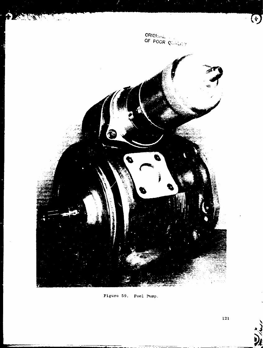
C)RIG!:',,;__
OF POOR Q:..;.L,:"."
....
121
I
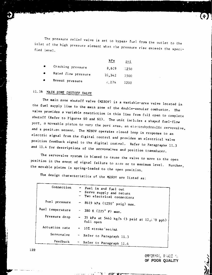
The pressure relief valve is set to bypas_ fuel from the outlet to the
inlet of the high pressure element when the pressure rise e×ceeds the speci-
Cracking pressure
Rated flow pressure
Reseat pressure
lied level.
o 8,619 ].250
10,342 1500
$,274 1200
11.16 MAIN ZONE SHUTOFF VAL_/E
The main zone shutoff valve (MZSOV) is a variable-area valve located in
the fuel supply line to the main zone of the double-annular combustor. The
valve provides a variable restriction in this line from full open to complete
shutoff (Refer to Figures 60 and 61). The unit includes a shaped fuel-flow
port, a moveable piston to vary the port area, an electrohydraulic servovalve,
and a posit_on sensor. The MZSOV operates closed loop in response to an
electric signal from _he digital control and provides an electrical valve
position feedback signal to the digital control. Refer to Paragraphs 11.3
and 11.4 for descriptions of the servovalves and position transducer.
_"_ne servovalve system is biased to cause the valve to move to the open
position in the event of signal failure to zero or to maximum level. Further,
the movable piston is spring-loaded to the open position.
The desigv, characteristics of the M/SOV are listed as:
Connection
Fuel pressure
Fuel temperature
Pressure drop
Actuation rate
Servovalve
Feedback
- Fuel in and fuel out
- Servo supply and return
- Twe electrical connector_
- 8619 kPa (1250" psig) max.
- 380 K (225 ° F) max.
- 35 kPa at 54&3 kg/h (5 psid at 12,C_0 pph)
full open
- 10% stroke'sec/mA
- Refer to Paragraph 11.3
- Refer to Paragraph Ii.4
122
___ - _ m,._ _-=_
OR'_!?!_,L F,-_,CZ_,:
OF POOR QUALITY

0:>
f
00
0
0
0
O"
,,M
4_
0O9
0:>
0
[/2
0
123
m

ORIGINAL PAGe. i_
OF POOR QUALITY
!
;>
e-(
::>
0
0L_
°
124

11.17 PILOT ZONE RESET VALVE
The pilot zone reset valve is a two-position valve located in the fuel
supply line to the pilot zone of the double-annular combustor. This valve
provides two levels of pilot zone fuel flo_ restriction in this line - full
closed or full cpen. This valve is identical to the main zone shutoff valve
described in Paragraph 1!.16, except it does not include a position feedback
sensor. Figure 62 is a photograph of the valve. The pilot zone reset valve
operates open loop in response to an electric signal from the digital con-
trol. Refer to Paragraph 11.3 for description of the servovalve.
_ne servovalve system is biased to cause the valve to move to the open
position in the event of loss of electric signal. Further, the movable pis-
ton is spring-loaded to the open position.
Connections
Fuel pressure
Fuel temperature
Pressure drop
Actuation rate
Servovalve[..
- Fuel in and fuel out
- Servo supply and return
- One electrical signal
- 8619 kPa (1250 ° psig) max.
- 380 K (225 ° F) max.
- 35 kPa max. at 5443 kg/h (5 psid
12,000 pph) full open
- 1% stroke/sec/mA
- Refer to 11.3
max. at
11.18 AIR VALVE ACTUATORS
The air valve actuator is an assembly of a linear hydraulic (engine
fuel) piston actuator, a two-stage electrohydraulic servovalve, and an
LVPT position feedback transducer. Figure 63 is a schematic of the actuator.
This is an FI011GV master actuator, except modified to include an LVFT
instead of an LVDT. Actuators of this type are used on the E 3 for actuation
of all three clearance co, trol valves anJ for the ganged start bleed valves.
The design characteristics of the air valve actuator are listed as follows:
Is5

OF PO'3R _UA__IrY
Su_pplv"Serv°
ischarge]
Figure 62. Pilot Zone Reset Valve.
126

°
127 \

Stroke
_rea, head end
Area, rod end
Dia, rod
Servova]ve
Feedback
3.BI cm (1.5 it,.)
20.06 cm 2 (3.11 in 2)
17.22 cm 2 (2.67 in 2)
!.905 cm (0.75 in.)
Ref. 11.3, Standard
Ref. 11.4
r_ ""J'.- I',
11.19 STATOR ACTUATORS
The stator actuators (two) are fuel-operated, linear piston actuators.
These are CF6 actuators, except that the stroke has been modified for the
E 3
Design characteristics of the the stator actuators are listed as:
Area, head end
Area, rod end
Stro_e
].8.90 cm 2 (2.93 in. 2)
16.90 cm 2 (2.62 in. 2)
8.072 cm (3.178 in.)
11.20 COMPRESSOR CLEARANCE CONTROL VALVE
The compressor clearance control valve is a continuously variable air
valve that has two inlet ports and one outlet port. The valve provides
variable-area airflow paths from each inlet port to the common outlet port.
Figure 64 is a photograph of the valve _nd Figure 65 is a cross section.
A rotary valve containing shaped flow ports f_r both inlet passages is
located within the valve body. An external lever attached to the rotary
valve axis provides valve rotation in response to linear input from the com-
pressor learance valve actuator (described in Paragraph 11.18).
Inlet
A
Inlet
B
Inlet
Percent Pressure,
Open I kPa (psia)
!00 I 741.2 (107.5)
28 1850.8 (123.4)i
0 ! 1172 (170)
i00 i 672.3 (97.5)i
I
Air
Temp,
K (° F)
656 (720)
656 (720)
Airflow,
kg/s (pps)
0.962 (2.12)
0.386 (0_85)
297 (75)
672 (750) 0.576 (1.27)
*0.227 kg/s (0.5 ppm max.)
128

_4RI_I_IAt" PAGE I_
OF POOR QUA! ITY
I Casing
Coolin_
Exhau st
Air
Figu_'e 64. Compressor Cleara_ _ Cc n'•ol Valve.
129
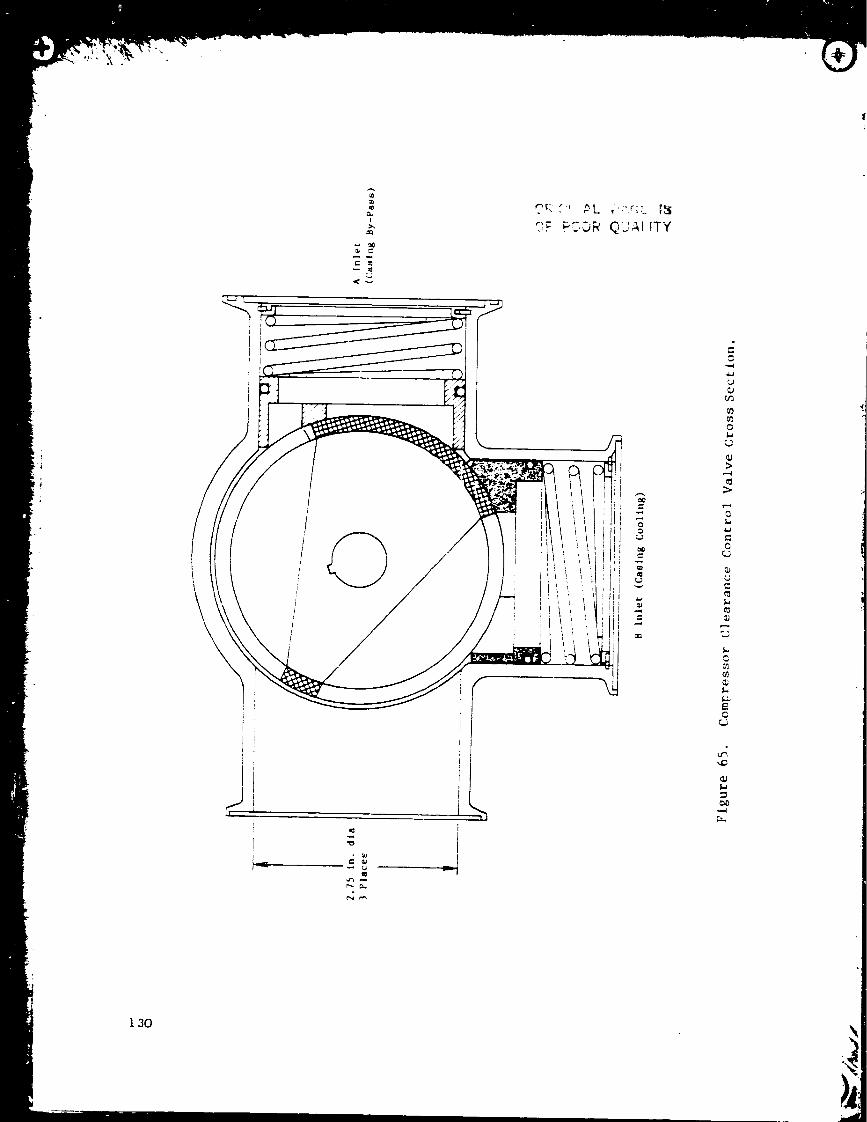
/
\
J
_L
J
oN
I
>
o
-Z,
C
Nc
130

ii .2 i START BLEED VALVE
Start bleed airflow on the E3 is controlled by four identical 8.89 cm
(3.5-in.)-diameter butterfly valves. FiBure 66 is a cross section of this
valve. The four valves are positioned through a unison ring by an air valve
actuator (described in Paragraph 1i.18).
Design operation characteristics of the start bleed valve are listed
below:
Inlet air temperature
Inlet air pressure
Actuation time
Failure direction
Airflow
220 to 611K (65 ° to 640 ° F)
103.4 to 689.5 kPa (15 to I00 ps:_)
1.5 sec
Closed
0.376 kg/s, 340 K, 4.82 kPa (0.83 pps,
152 ' F, 0.7 psig)
1i.22 TURBINE CLEARANCE CONTROL _'ALVES
One 8.89-cm (3.5-in.) diameter butterfly valve identical to the start
bleed valve described in Paragraph 11.21 is used in each of the two turbine
clearance control systems to control the flow of casing cooling airflow°
Each valve is positioned by an air valve actuator as described in Paragraph
11.18.
11.23 START RANGE TURBINE COOLING VALVE
This is a 6.35-cm (2.5-in.), in-line, air actuated poppet valve. Figure
67 shows a cutaway schematic of this valve, lwo valves are used for each
engine and operated in parallel By a solenoid-driven pilot valve. When the
signal port is vented to ambient, valve inlet pressure holds the valve in the
closed position shown in Figure 67. When PS3 is applied to the signal port
the valve opens. Design characteristics of the valve are listed below.
131
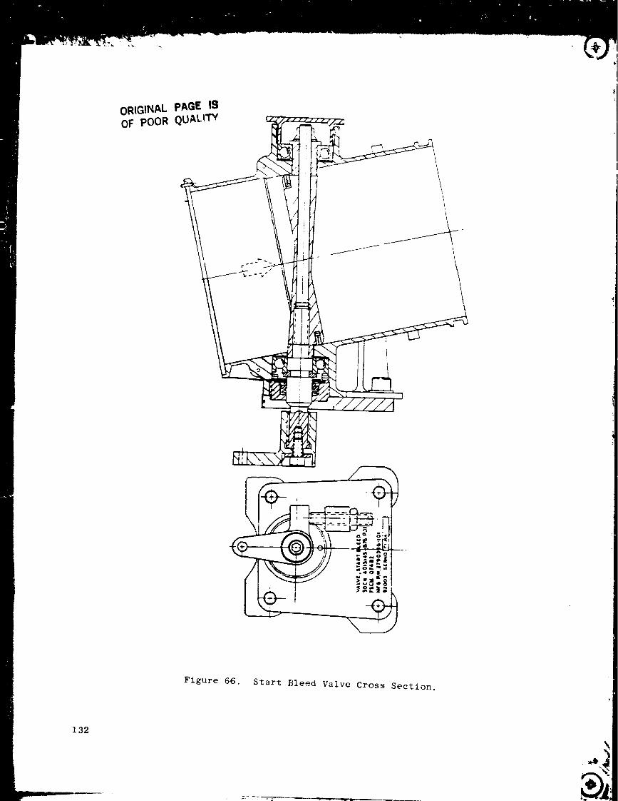
ORIGINAL pAGE ISOF POOR QUALITY
Ffgure 66. Start Bleed Valve Cross Section.
132

m_
\
ORIGINAL PA_ I_OF POOR' QUALITy
!
d
o
000
e_
o
133

i Inlet air temperature
Inlet air mress_re
!I Airfiow
!
I Pressure differentialI
I Actuation time
l
ORIGINAL PAGE IS
OF POOR QUALITY
220 to 505 K (-65* to 450 ° F)
138 to 414 kPa (20 to 60 psia)
0.227 kg/s, 365 kPa, 490 K (0.5 pps at
53 psia, 422 ° F)
3.45 kPa (0.5 psi) at design flow
2 sec
i..24 START RANGE TURBINE COOLING SOLENOID
This is a three--day pneumatic solenoid valve that controls the signal
pressure to the start range turbine cooling valves described in Paragraph
11.23. Dusign characteristics of this valve are listed below.
Operating pressure
Temperature - Ambient
- Fluid
- Body
Electrical - Voltage
- Current
34.5 to 6895 kPa (5 to i000 psig)
220 to 450 K (-65* to 350 ° F)
220 to 783 K (-65" to 950 ° F)
478 K (400 ° F) Max.
22-29 volts d.c.
1.25 amps
11.25 ELECTRICAL CABLES
There are seven on-engine cable assemblies used for interconnecting the
various control components and sensors. Generally, AWG 20, stranded, nickel-
plated copper wire is used. Functionally, associaLed wires are run as metal-
shielded twisted pairs and triplets within cables consisting o_ a glass-fiber
braid covered by an outer metallic (nickel) braid. Connectors are of stainless
steel and are mechanically attached to the outer metallic braid to carry
handling loads and provide shielding grounds. Figure 68 shows typical cable
construction.
134

eJ
...-- ._IE
- _,_ r/_" ?
e
.,,...,,
a
,,,,?
ga
J
W TM_ .- -_
- _ _;___-_
I'
_o _
i;t tS I.
,_ _'_
i---'----r
J
-e4
q_
.,4
135

12.0 SYSTEM DIFFERENCES FOR CORE ENGINE
The control and fuel system for the core engine will be the same as the
ICLS syteu described in the previous sections of this report, with the follow-
ing exceptions:
All LP turbine-related functions and hardware are deleted. Deleted
functions are fan speed governing and LPT clearance con:rol.
Deleted components are the fan speed sensor, the TI2 sensor, and
all components involved in LP turbine clearance control.
The digital control will be an off-engine rather than on-engine
configuration. Electrically, the controls will be virtually
identical.
The compressor stator control function will not be used. A test
facility control system with individual stage control capability
will be used to provide experimental flexibility.
Only three of the 35 EPT discharge thermocouples (T42) will be used
for the control system rather than the _ive on the ICLS engine.
"his change was made in order to provide more turbine discharge
profile data on the initial engine run, while still providing an
adequately averaged, control-dedicated T42 signal.
136

13.0 SYSTEM DIFFERENCES FOR THE FLTGHT PROPULSION SYSTEM ENGINE
One of the first steps in the E 3 program was the preliminary definition
of a production design (termed FPS, Flight Propulsion System). This was done
in 1978. The ICLS control and fuel system described in this report was
designed to demonstrate FPS technology and, thus, is essentially the same as
the currently envisioned FPS or production engine system. The few differences
are described below.
i.
o
.
6.
Ultimately, a single-channel digital control, as on the core and
ICLS engines, is considered feasible for a production E 3. However,
for initial service, dual redundant controls with hydromechanical
overspeed protection (but no other hydromechanical backup) is
considered necessary to achieve the desired operational reliability.
It is expected that in-service development will ultimately produce
a digital control with reliability equivalent to current controls so
that redundant controls are no longer necessary.
Improvements in digital control power supply size and efficiency
will result from the introduction of an FPS alternator tailored to
the E 3 digital control. The FI01 alternator, used for the core
and ICLS to avoid the costly devel)pment of a new design, required
power supply design compromises.
Th_ Waste-Heat Recovery System (WHRS) concept that emerged from
early E 3 design studies would probably be included on a production
E3. The WHRS trausfers heat from the compressor bleed air (used for
aircraft environmental control) to the engine fuel sytem. This
system would return energy that is currently wasted to the engine
cycle and also would eliminate the need for fan air cooling of the
environmental bleed air used in current aircraft. For a typical
cruise condition, the design study indicated that the WHRS will pro-
vide a net sfc reduction of approximately 0.8%. Figure 69 is a
schematic of the WHRS. The system is further described in Reference
2. A modification of the WHRS is described, which can be a help in
accommodating future fuels with higher freezing points by providing
controlled fuel tank heating.
A thrust reverser would be incorporated on a productio,, E 3, and con-
trol of the reverser would he performed by the engine control system.
The reverser control strategy can be added to the digital control with
little effect on the computing elements. The strategy will include the
basic reverser sequencing control, interlocks to minimize misdirected
thrust during reverse transients, and core stator reset to a_oid re-
ingestion-induced engine surge. The reverser is not included in the E3
demomstrator program, and no detailed actuation or cont_o! _;vstem design
work has been performed for it.
137

OR',G!NAL PAGE 19OF POOR QUALITY
L
..o
;>-,
OJ
>
OL;
U3
,v
138

APPENDIX
139

Z= ,-,o ,,.: C= =:: ,_, _m -m

o_
C
::E:
C
C
,£
C
C,4.,
S.,
CC
°i•g.._
C
C
E
c_
_C
o_
Q_
c_
,C
C
¢_ ¢_
C
c_
C *
C
<
C,'
?'
,'CL
¢_
*C
¢3
,..., ¢:
¢[
p
:>,,
p.
<
q_ ¢3
C
0 04.d ._
E 6
C
w
C u c_
•._ _ .__o,-_ _ c_
c_
¢c
4
_ _ C C
v _o _
_.,_ '_ _
_ _.,_
:_ ...._
"G _ ..._
Q3 "
._ C
_., °,._ ¢_ _._ •
C, ¢; c
I 0 ""_
CI.,o_
U
S., '_
¢ C
._ G m._ ._
C
. ..m
C c _-,
r*
z_
L
CC _'_
q ..2C C_
C
%.
I.."i
,,Q
,b,
E
¢Q
J
•,r, ¢_
,C.
C
C
o_
41

0o.._
_ ¢,'% u_

0o,.__.a Qj
u
u

r r
ORIG;R,_ PAG_ ISOF pOOR QUA! .tTY
C°,,w
0v .w
,,w¢ U
•,-, e.,
CX
I,,.,,0
{,.;0},.,m.
..w
C
m
O.w
_ UE •= 7L. O_ Em _
O
uO
144u
•,-, _
r"
L
L
•,W E ¢
C
>
°,-_
O C =
: ® ._
U _ •
_ e" e.0 -,-, _ .,w
,._ (5_ 0
_.,_ 0
e,, .%;
..,.,Cp,
U 0 I,.,
.w _ ..- e"
<_ _ _
Z
C
¢
C
--
m
..w
o...w
...w
_) ,..weL
.,w_j w_
_-- (p
.,w ,,_
e_
0..w :_
•,w ._¢
0 u
,..w
E
U O
Ue- C
_b
_4Dm0
.C
O
O
%J
C
m
O
m
O U
Ee
u o(j .,w
u
O
C
¢
O
6,C
>..w
,..w
OM
C,,._
_ m
..w
_ m
= CE,'-"
m _
O
4
C _K• C
o. ..w
u
C _
•= E
C u_ U
N _ e-
E e'.,w
m ¢ t_
_ S
,.-. _ ..w W ,.w
E .= • x
fO U "_
E-wC
<
O
," ¢'_ .,w _--
U L_
O C m
e," E _
O _ _
..w i.IS
_ • °.i •
..W ..W .,W
6' U ,--WC m
•.W Iw._='D ".,_
_ -,,W
U _p-,W
<
_DI .,W
L_
c _
?" ¢
N •
E
_ J= U
¢ "_ I
m _
,_ ¢ x-
.4_w
•_._ ¢
.,.w ..w
,..w
i_ ¸.

_J
0¢;
QJ
0
L.0
U0
1.i
r-
I,J
E
0
_J
°,..d
0E
c-O
°,__.J Q;
0
_j e-
-_ e',
Q; ._ !•J Q;
_ t_ _
_-._ _ _
p.
Q_"0 I;QJ"_ "0
_J
Q; z_
CJ_J
Q; _J
Q;
°,,_
t_
•,-, _ 0
•._ . _ _
"_ ""_ 0 _
$-0 .,_
-- -.- QJ 0 _;
Q; ._ _..,._
"._, ,,',,- PA(3E' IS
OF POOR QUAL:TY
•,,_ |
•-_ 0 0 Q;
•,._ _; _._
_ 0 _ m 0
:_ L, .._ _L
•,._ _ _ _
_0-,._ _ _._ _w _;
_0 _ ¢_ ,'_ .7_
_" G."_ _
"_ *,-_ r" .
,4D
145
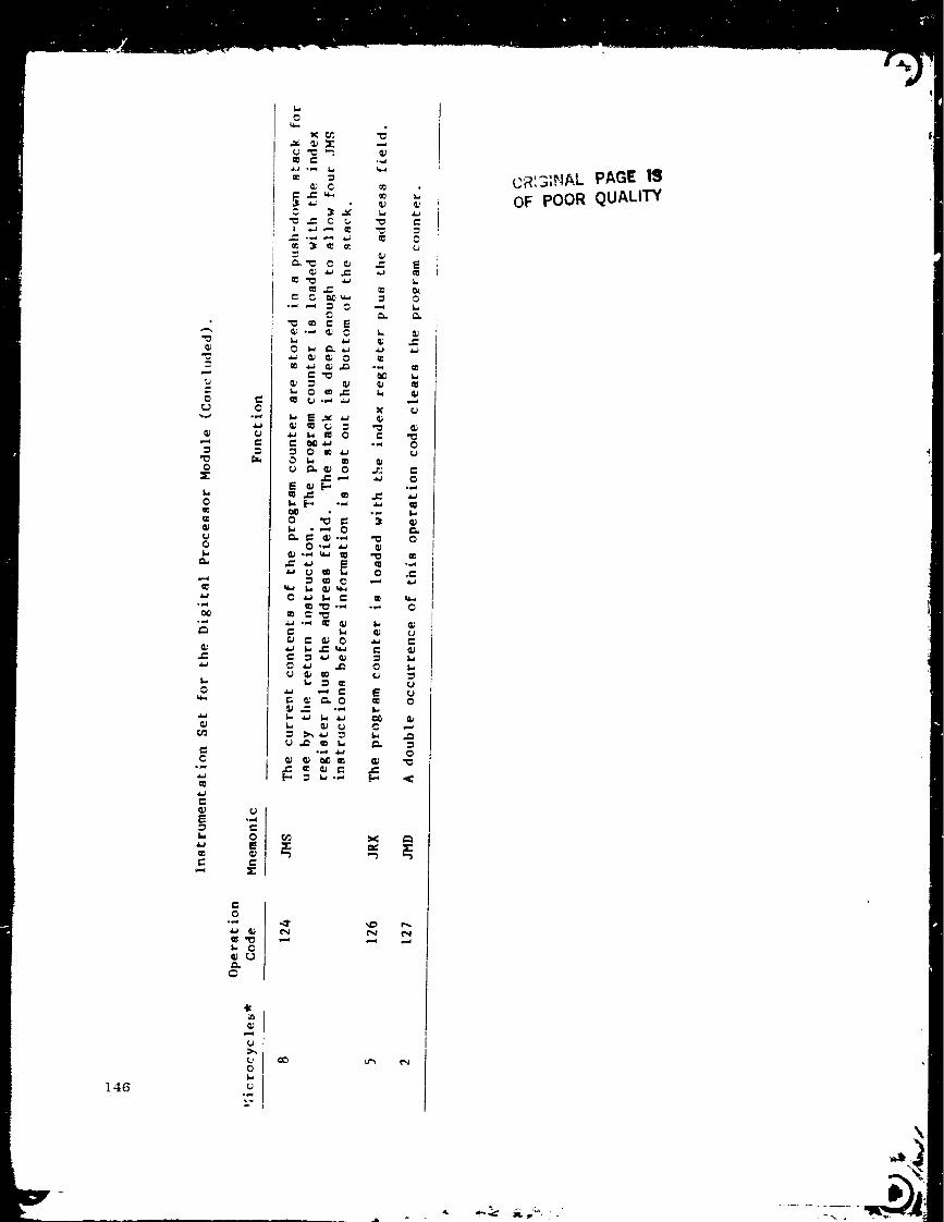
146
"E
o
o
Z¢L--
c°,_
,=
E
r-
o
u
o
o
0
L_o
c
c
c
u ¢_Q; oe-,._
E m_m ._ m
_ m c
u _ m
t¢,,,,d
e_
t.
L
e.
°_,_
c(J
c
p.
><
1',,,4
c
E
L.
cp
o
Q_
_J
Q;
u_Jo
Q_
o
<:
CR',3;,NAL PAGE
OF POOR QUALITY
•- . .. .

REFERENCES
I °
.
Boerstler, L.H., "Control Mode A_alysis for the E 3 Engine," G feral
Electric Company Report No. R78AEG646, 15 December 1978.
Coffinberry, G.A., '_aste-Heat Recovery System," General Electric Company
Report No. R81AEGS05, December 1981.
|
147


![Computational Engine Structural Analysis - NASA · Computational Engine Structural Analysis (NASA-T_] ... engine structural component modeling, (3) ... resistant fan blades using](https://static.fdocuments.in/doc/165x107/5ae5b62f7f8b9a29048c9bb9/computational-engine-structural-analysis-nasa-engine-structural-analysis-nasa-t.jpg)