ENERGY EFFICIENT EMBEDDED SYSTEM DESIGN FOR MEDICAL …
119
Virginia Commonwealth University Virginia Commonwealth University VCU Scholars Compass VCU Scholars Compass Theses and Dissertations Graduate School 2008 ENERGY EFFICIENT EMBEDDED SYSTEM DESIGN FOR MEDICAL ENERGY EFFICIENT EMBEDDED SYSTEM DESIGN FOR MEDICAL CARE SYSTEM USING WIRELESS SENSOR NETWORK CARE SYSTEM USING WIRELESS SENSOR NETWORK QI LI Virginia Commonwealth University Follow this and additional works at: https://scholarscompass.vcu.edu/etd Part of the Computer Sciences Commons © The Author Downloaded from Downloaded from https://scholarscompass.vcu.edu/etd/1624 This Thesis is brought to you for free and open access by the Graduate School at VCU Scholars Compass. It has been accepted for inclusion in Theses and Dissertations by an authorized administrator of VCU Scholars Compass. For more information, please contact [email protected].
Transcript of ENERGY EFFICIENT EMBEDDED SYSTEM DESIGN FOR MEDICAL …
Virginia Commonwealth University Virginia Commonwealth University
VCU Scholars Compass VCU Scholars Compass
Theses and Dissertations Graduate School
2008
ENERGY EFFICIENT EMBEDDED SYSTEM DESIGN FOR MEDICAL ENERGY EFFICIENT EMBEDDED SYSTEM DESIGN FOR MEDICAL
CARE SYSTEM USING WIRELESS SENSOR NETWORK CARE SYSTEM USING WIRELESS SENSOR NETWORK
QI LI Virginia Commonwealth University
Follow this and additional works at: https://scholarscompass.vcu.edu/etd
Part of the Computer Sciences Commons
© The Author
Downloaded from Downloaded from https://scholarscompass.vcu.edu/etd/1624
This Thesis is brought to you for free and open access by the Graduate School at VCU Scholars Compass. It has been accepted for inclusion in Theses and Dissertations by an authorized administrator of VCU Scholars Compass. For more information, please contact [email protected].

ENERGY EFFICIENT EMBEDDED SYSTEM DESIGN FOR
MEDICAL CARE SYSTEM USING WIRELESS SENSOR
NETWORK
A Thesis submitted in partial fulfillment of the requirements for the degree of Master of Science at Virginia Commonwealth University.
by
QI LI Bachelor of Science, Beijing University of Posts and Telecommunications, China, 2007
Director: Dr. JU WANG ASSISTANT PROFESSOR, DEPARTMENT OF COMPUTER SCIENCE
Virginia Commonwealth University Richmond, Virginia
December 2008

Acknowledgements
First and foremost, I would like to thank Dr. Ju Wang for being such a great
advisor and introducing me to the area of Wireless Sensor Network and Embedded
Systems which are always my favorite topics in computer engineering.
I would also like to thank Dr. Azhar Rafiq for involving me into the NASA Mitac
project which gives me a great opportunity to learn how to design and implement
embedded system for real world applications. I had a lot of fun programming and testing
with different kinds of embedded system platforms provided by Dr. Rafiq and learned a lot
of coding and testing skill through it.
Last but not least, I would like to thank Dr. James E. Ames who is kindly being a
committee member of mine to help on my master thesis.

ii
Table of Contents Page
Acknowledgements .............................................................................................................. i
List of Tables ...................................................................................................................... v
List of Figures .................................................................................................................... vi
Abstract ............................................................................................................................. vii
Chapter
1 Introduction ....................................................................................................... 1
2 System Overview .............................................................................................. 4
2.1 Wireless Sensor Network Topology ....................................................... 4
2.2 Low Power Consumption and Device Portability .................................. 7
2.3 Biomedical Sensor Diversity .................................................................. 8
2.4 Computation Power and Device Compatibility ...................................... 8
3 Embedded System Hardware Platform Design and Implementation .............. 11
3.1 MCU Wireless Device .......................................................................... 11
3.2 Board Schematic Design ...................................................................... 13
3.3 Board Layout and Routing ................................................................... 14
3.3.1 Power Circuit Layout ................................................................... 14
3.3.2 Sensor IO and General IO Layout ............................................... 16
3.3.3 Wireless Circuit Layout ............................................................... 18
3.3.4 Board Routing Concern ............................................................... 19
3.4 Board Soldering and Circuit Unit Testing ............................................ 20
iii
4 Embedded System Software Design and Implementation .............................. 22
4.1 Software Design Guidelines ................................................................. 22
4.2 Low Level Programming ...................................................................... 22
4.2.1 Setup and Radio Transceiver Configuration ............................... 22
4.2.2 Interrupts ...................................................................................... 24
4.2.3 RSSI, ED, CCA and LQI Measurements .................................... 25
4.2.4 Basic and Extended Operating Mode and State Changes ............ 26
4.3 High Level Programming ..................................................................... 28
4.3.1 Data Collecting and Packet Format ............................................. 28
4.3.2 Wireless Transmission Control Using Library Functions ........... 32
4.3.3 CO2 Module Plug and Play ......................................................... 33
4.3.4 Embedded Program Debugging ................................................... 34
5 Gumstix Module Setup and Configuration ..................................................... 36
5.1 Introduction to Gumstix and Embedded Linux .................................... 36
5.2 Gumstix Configuration and Arm-Linux Setup ..................................... 36
5.3 Cross Compile Environment. ............................................................... 37
5.4 User Interface Application Test on Gumstix ........................................ 37
6 User Interface Application Design for Laptop and Web ................................ 38
6.1 Rich GUI Design .................................................................................. 38
6.1.1 Friendly Interface Design and Program Portability ..................... 38
6.1.2 Multithreading Concern ............................................................... 40

iv
6.2 Real Time Web Application and AJAX ............................................... 40
6.2.1 Brief Introduction for Real Time Web Technology .................... 40
6.2.2 Web Application Design ............................................................. 41
7 Project Current Status and Future Work ......................................................... 42
References ......................................................................................................................... 43
Appendices ........................................................................................................................ 45
A Project Resources Layout on Share Drive ...................................................... 45
B Source Code of Embedded Program ............................................................... 46
C Source Code of GUI Program ......................................................................... 84

v
List of Tables Page
Table 1: Comparison between Bluetooth and ZigBee. ....................................................... 6

vi
List of Figures Page
Figure 1: Application Architecture ..................................................................................... 3
Figure 2: Hybrid Wireless Sensor Network Topology Composed of Star Cluster Tree and
Mesh .................................................................................................................................... 5
Figure 3: ZigBee Network Stack ........................................................................................ 7
Figure 4: Prototype Processing Terminal based on Gumstix ............................................ 10
Figure 5: ATmega2560 MCU and AT86RF230 RF Chip. ............................................... 11
Figure 6: Schematic of MCU ............................................................................................ 13
Figure 7: Board Layout Highlighting 5v Power Circuit Trace ......................................... 16
Figure 8: Board Layout Highlighting Jumper and MAX232 chip .................................... 17
Figure 9: Board Layout Highlighting the Wireless Critical Section ................................. 19
Figure 10: Flow Chart of Initialization of ZigBee Wireless Chip .................................... 23
Figure 11: State Diagram of Basic Operating Mode ......................................................... 27
Figure 12: Application GUI .............................................................................................. 39

Abstract
ENERGY EFFICIENT EMBEDDED SYSTEM DESIGN FOR MEDICAL CARE
SYSTEM USING WIRELESS SENSOR NETWORK
By Qi Li, MS
A thesis submitted in partial fulfillment of the requirements for the degree of Master of Science at Virginia Commonwealth University.
Virginia Commonwealth University, 2008
Major Director: Dr. Ju Wang Assistant Professor, Department of Computer Science
Recent surveys on medical service systems show that the cost of patient monitoring has
grown significantly. The widespread use of portable digital medical device makes it
possible to provide a more comprehensive tracking of patient conditions. However, the
development of a full scale, distributed health monitoring system is much delayed due to
the lack of efficient wireless communication in a large distributed network. This becomes a
challenging research topic which is to find a way to provide accurate and real time patient
information to medical experts in a fast, efficient and cost effective fashion. This paper
proposes a novel solution on building a system which links patients and doctors together
using embedded system technology and wireless sensor network. The content presented in
this thesis introduces the design and implement of such a system.

1
1. Introduction
In the past twenty years, development of various IT technologies has been growing in an
extremely fast speed and an era fulfilled with electronic devices and micro computers has
come which is making significant influence on our life. Personal computers, server clusters,
large storage systems and Internet are widely used in every place of our life, including the
modern medical care systems.
Meanwhile how to efficiently use these technologies to serve in the medical service system
has also become an important issue. More and more people are involved in this research
area and bring new ideas. Thank to the recent progress in biomedical engineering, it is
possible nowadays to use sophisticated biomedical sensors to retrieve health information
from human body to diagnose different sickness of patients. However, using the traditional
"wired giant equipments" to collect data from biomedical sensors is neither applicable nor
efficient. Here we propose a new system which consists of two subsystems to change this
kind of situation. One subsystem addresses deploying biomedical sensors and collecting
data through low power consumption embedded system device with short range wireless
capability. The other subsystem provides data routing, displaying, sharing and analyzing
combined with computer assisted diagnose technology.

2
The feature of this idea is that we use a large portion of current cutting edge technologies
such as compact powerful embedded system, wireless sensor network, real time web
publishing and medical signal processing which are already very mature. In particular,
compact embedded system device provides an extreme portability and is easy to setup and
deploy.
On the other hand, wireless sensor networks are already used in some biomedical
applications [1, 2]. Main advantages of such systems are and low cost, high mobility, easy
to deploy and low power consumption. Typically medical nodes will transport critical
physiological readings from patients through an interconnected wireless ad hoc network to
a coordinator node (such as PAN in [3]). The coordinate node further routes data to a
information deposit node, which provide real time web publishing and support remote
monitoring clients and remote system management. Medical signal processing enhances
the speed of diagnose and decision making in terms of saving a lot medical resources.
To illustrate the capability of the proposed system, we provide a simplified medical
scenario below. Imagine that a doctor can stay at home and sit in front of his computer and
all he need to do is open his web browser then he can get all the information from his
current patients who might stay either at hospital or at home. With the help of the medical
AI soft-bot system which classifies and analyzes those data, he can easily diagnose and

3
make decisions on the current status of patients and give out his instructions. Figure 1
shows the general architecture of this system.
Figure 1: Application Architecture
The rest of this thesis will discuss different components and technologies used. Chapter 2
provides an overview of the system components. In chapter 3 and chapter 4, we provide
detailed hardware design and integration and software architecture of the medical sensor
node and the communication protocol. Chapter 5 and 6 discusses an implementation of a
mobile client terminal and visualization of the data.

4
2. System Overview
2.1 Wireless Sensor Network Topology
It is important to give a clear definition of network topology. Network topology is the
study of the arrangement or mapping of the elements of a network, especially the physical
and logical interconnections between nodes.[11] Traditional network topology like Bus,
Star, Ring, Mesh, Tree, Hybrid and Point to Point are already widely used in various wired
and wireless networks and each of them has their advantages and disadvantages. For
example, in a Star network, each node can talk to all other nodes using a very short route
which contains only 2 hops but at the same time all nodes rely on the central node very
much which might have large traffic congestion and if the central node is down, the whole
network will fail. Thus, it is every important to choose a network topology fit very well to
the requirements of application so that we can maximize the advantages and minimize or
avoid the disadvantages.
Since there is very rare monotone network topology in the real world application, we also
choose a hybrid network topology combined with Star, Cluster Tree and Mesh to form our
network and the portion of each of them can be different depends on the requirements and
the available resources. There are two types of nodes existing in wireless sensor network.
One is full function node which collects data and the other one is coordinator node which
receives data from the full function nodes and route data out of the wireless sensor network.

5
Figure 2 shows how to define coordinator nodes and device nodes in these network
topologies.
Figure 2: Hybrid Wireless Network Topology Combined with Star Cluster Tree and
Mesh
We choose ZigBee [5] protocol to fit on this wireless sensor network topology since the
new standard offers long battery life, reliability, automatic or semiautomatic installation,

6
the ability to easily add or remove network nodes, signals that can pass through walls and
ceiling, and low system cost which are very important to medical service oriented
applications.[4] Table 1 shows some of the specifications of Bluetooth technology
compared with ZigBee technology.
Bluetooth ZigBee
Modulation Technique Frequency Hopping Spread
Spectrum (FHSS)
Direct Sequence Spread
Spectrum (DSSS)
Protocol Stack Size 250KBytes 28KBytes
Maximum Network Speed 1Mbit/s 250Kbit/s
Network Range 1 or 100 meters depending
on radio class
Up to 70 meters
Typical Network Join Time 3 seconds 30 milliseconds
Table 1: Specification Comparison between Bluetooth and ZigBee
ZigBee uses 2.4GHz spectrum with 11-26 different channel and can achieve a data rate up
to 250 kbps.[5] Although this is not fast compared to the Bluetooth technology in terms of
speed, it has better operating range and ultra low power consumption advantages.
Biomedical data transmission is not like multimedia transmission which requires very high
network speed to achieve smooth performance. It focuses on features more like network
reliability, packet consistency and so on. Figure 3 shows the ZigBee network stack.

7
Figure 3: ZigBee Network Stack
2.2 Low Power Consumption and Device Portability
Low power consumption requires that the hardware platform should be operated using
general battery and last as long as possible without sacrificing performance. So it is
necessary to design the system with cost and energy efficient components and protocols.
In terms of components, there are lots of energy efficient microcontroller units and
wireless chips which have the sleep mode to reduce the current so that to save the battery
life when they are not transmitting/receiving data. Considering the cost of the populating

8
boards, we use the same design for full function node and coordinator node, but on the
coordinator node side we need to associate the device with a powerful processing terminal
such as a laptop or a handheld device which will be discussed in later chapters.
Considering the device portability, the size of the device will become very significant in
the design. There are a lot of factors which can influence the size of the board like total
number of jumpers, different function circuits, package type of the component, total
number of layers on the board, size of battery, size of different kinds of sensors and so on.
Since it is still under testing and developing process, the goal is that we try to make as
much compatibility as possible while keeping the size of the board as small as possible.
2.3 Biomedical Sensor Diversity
Monitoring patient health status requires a lot of different information but considering the
size of the device we can only pick up sensors with compact size and do not require too
much power to drive. So currently under testing we have Carbon Dioxide Sensor (CO2),
Galvanic Skin Response Sensor (GSR), Pulse Oxygen Sensor (Pulse OX), Temperature
Sensor (TEMP) and Accelerometer Sensor (ACC) which provide the inspiration rate,
expiration rate, respiration rate, heart rate, body temperature, body movement and so on.
2.4 Computation Power and Device Compatibility

9
As full function node, it is important to have enough computational ability to collect and
transmit data. So obviously when choosing a microcontroller we need to consider its
running frequency, memory size, amount of general and special IOs, amount of general
hard interrupt which can be supported and amount of TIMER/COUNTER. A better class
of 8 bit microcontroller can match this requirement very well.
The coordinator node side which would be a combination of partial full function node
without biomedical sensors and a processing terminal which has stronger processer for
running user interface application and WIFI/3G connectivity to Internet to route the data
through the Internet. In terms of processing terminal, a general small laptop could be an
ideal candidate but its disadvantage is the size and battery life which leads to low mobility.
So we are going to design the processing terminal based on Gumstix as a prototype which
is a very compact platform perfect for developing new handheld devices. It uses a 32
RISC ARM -architecture processor which has a clock frequency running at 600MHz with
128Mb on board RAM. The NAND flash is only 32Mb but a large micro-SD card can
easily cover this disadvantage and it supports a full 2.6 kernel embedded Linux. Figure 4
shows the Gumstix prototype.

10
Figure 4: Prototype Processing Terminal based on Gumstix

11
3. Embedded System Hardware Platform Design and
Implementation
3.1 MCU Wireless Device
After doing some research, we pick up the Atmel product, the ATmega2560 8 bit
microcontroller and AT86RF230 ZigBee wireless chip since Atmel provides a very good
set of developing tools and schematic reference. Chip images are showed in Figure 5.
Figure 5: ATmega2560 MCU and AT86RF230 RF Chip
ATmega2560 provides sixteen 10-bit ADC channels and four programmable UARTs [7]
which can easily solve the diversity requirement of biomedical sensors since it covers both
analog and digital sensors and new sensors can be integrated to the board without too much
hardware modifications in the future. It also can hit a 16 MIPS [7] level computation
capability when running on 16 MHz [7] which is powerful enough for data collecting and

12
transmission. The 256K Bytes flash can store the full ZigBee protocol stack and our
embedded program.
AT86RF230 provides programmable output power from -17 dBm up to 3 dBm (20µW to
2.0 mw) [8] which solves the range and signal strength problem and it also let you make a
trade off between the range, signal strength and power consumption. The ultra-low power
consumption brings 20 nA sleeping, 15.5 mA receiving and 16.5 mA transmitting [8]
which roughly calculated can last 2 years with a normal 9v battery.
Three different communication ports are used in this embedded system including SPI,
UART and ADC.
SPI (Serial Peripheral Interface) is used to program the microcontroller chip while it is also
used as the communication link between microcontroller and the ZigBee wireless chip.
UART (Universal Asynchronous Receiver/Transmitter) is used to collect data from CO2
sensor and Pulse OX sensor and it is also used to communicate with the processing
terminal through a serial cable using the RS232 protocol. ADC (Analog to Digital
Converter) channels are used to connect analog sensors and convert the analog data to
digital data then send to the microcontroller for processing.

13
3.2 Board Schematic Design
We separate the board schematic to five different sheets which are “CPU_FLASH”,
“POWER”, “SENSOR_IO_LED”, “802.15.4_ZIGBEE” and “RS232”.
In the previous generation we also includes the USB to RS232 circuits and the battery
charging circuit, however unfortunately they brought a lot of unpredictable hardware
problems when we started testing the boards. So we decide to remove those two features in
this generation design and this not only makes the board size much smaller but also more
stable and reliable. Those two parts circuit will be redesigned as part of the extension
boards in the future. Figure 6 shows the schematic of MCU part.
Figure 6: Schematic of MCU

14
3.3 Board Layout and Routing
Board Layout is the way where you put different component like chips, resistors, inductors,
capacitors on to the board. When current flows through these components, it will form
some kind of electronic magnitude which may lead to some critical interference to the
functionality of other circuits. Thus, it is important to analyze the component layout before
doing it.
Board Routing is the way you use the Routing software (Router) to route the metal traces
which connect different components together. General Routing software will provide
automatically routing which will help you finish the task, however bad layout or board
without enough size may cause the Router failed. In this case, some manual routing will be
involved to solve the problem.
3.3.1 Power Circuit Layout
Power Circuit on the board includes two major voltage regulator circuits which are 3.3v
voltage regulator circuit and 5.0v voltage regulator circuit. 5.0v is the voltage supply for
the CO2 sensor on the full function node side and for the Gumstix handheld device on the
coordinator node side. 3.3v is the standard voltage supply for the microcontroller and other
chips and sensors. They are both industrial standard which means if additional extension
board or other biomedical sensors need to be integrated into our application, they can be

15
powered up by one of them. There is also a filtering circuit designed for stabilizing the
voltage on AVCC pin of the Microcontroller.
The critical part of the power circuit layout is that it usually generates electrical magnitude
which will have significant interference to the RF circuit. In the last generation of the
board design, the RF circuit always fails whenever CO2 sensor is connected to the board
and the reason is that there is a 5v trace passes through the RF circuit which generates the
interference. So in the new version, we carefully separate the RF circuit and power circuit
as far as possible and make sure there is no 5v trace pass through the RF circuit. Figure 7
shows the 5v trace in the new layout.

16
Figure 7: Board Layout Highlighting 5v Power Circuit Trace
3.3.2 Sensor IO and General IO Layout
Sensor IO includes general jumpers and peripheral circuits for the biomedical sensors.
General IO includes the ISP (In System Programming) port and UART port for
communication with the processing terminals.

17
For biomedical sensors, the peripheral circuits only contain several resistors and capacitors
to balance and stabilize the input voltage so there is not too much design concern for them.
We follow the standard Atmel reference design for ISP port. For UART it is important to
point out that UART connected to biomedical sensors and connected to processing
terminals like laptop are using different voltage although the protocols are the same. So to
make the UART on our board talk directly to a laptop through a RS232 cable, a MAX232
chip is required in the design to amplify the signal strong enough. Finally we combine all
the output and input on a standard 20 pins jumper on our board. Figure 8 shows the jumper
and part of the IO circuits.

18
Figure 8: Board Layout Highlighting Jumper and MAX232 chip
3.3.3 Wireless Circuit Layout
This is the most important part of the embedded hardware platform design. Atmel provides
a lot of professional design consideration for this part of circuits, however, it will be hard
to include all of them and it is also not practical to implement all of them on a compact
board. Atmel’s reference board almost takes 2/3 size of our whole board. I will list a series
of these considerations and point out those really critical ones.
General consideration requires the separation of the analog circuit and digital circuit and
the antenna section. The routing of the RF output pins RFP (positive output to antenna)
and RFN (negative output to antenna) of the AT86RF230, which must be connected via a
series capacitor to the balun input, must be impedance controlled lines of 100 ohms
(differential impedance).[12] This is required to get best RF performance. All traces from
the radio to balun, and from the balun to the antenna must be designed symmetrically to
ensure that the two traces have the same impedance.[12] These two parts are important and
we try to maximize the completeness for the requirement on our boards.
Since noise is in evidently present on power and ground signals, as well as on other signal
lines, there is no perfect way of shortening or filtering traces to eliminate it.[12] To

19
effectively reduce the noise, all ground signals should be connected at one placed on the
board. Figure 9 shows the board layout of the wireless circuit critical sections.
Figure 9: Board Layout Highlighting the Wireless Critical Section
3.3.4 Board Routing Concern
As mentioned before, board routing can be easily done with the help of the automatic
router software. So usually it does not need the human interaction. But when automatic
routing fails, there are several other ways to finish routing.

20
The easiest way is to enlarge the size of the board. Automatic router fails because it cannot
find enough space to route the trace. So it can also be solved by using multiple layer
boards but this usually brings more cost when populating the board. Reduce the width of
the trace also helps the automatic router to finish its job, but the major PCB board
manufacture requires the 6mils as the smallest width.
If all of above strategies fail or cannot be achieved, manually route can be involved.
General way is that unroute the local area where some connections cannot be finished, and
with the help of the router, manually specify the direction and route the particular trace.
3.4 Board Soldering and Unit Testing
Board soldering and the unit functionality testing are the last two steps for the embedded
hardware platform design. Additional attention is required when soldering the ZigBee
wireless chip because bad soldering job may lead to unpredictable hardware failure which
is very hard to locate.
Unit functionality testing includes MCU programming testing, power supply voltage
testing, RS232 circuit testing and the most important RF circuit testing. We solder the
minimum requirement of the components to do the testing of each part, so if one circuit
fails, it is very easy to locate the problem. MCU programming testing usually comes first
since it only requires the microcontroller chip, some peripheral capacitors, a pull up

21
resistor for RESET pin and the ISP jumper. Power supply circuit test always comes as the
last, so previous testing will be all done with the help of external DC input.

22
4. Embedded System Software Design and Implementation
4.1 Software Design Guidelines
There are two separated embedded programs which are designed for the full function node
with biomedical sensors and the coordinator node with the processing terminal separately.
Both of them share the same part of controlling behavior of wireless chip to implement the
data transmitting and receiving between full function node and the coordinator node.
Data collecting will be another important part for the program running at full function node
side. And for the coordinator node, it only needs to dump data received from the wireless
sensor network through the UART connection to the processing terminal.
4.2 Low Level Programming
Here low level programming refers to the way how to control the behavior of the ZigBee
wireless chip.
4.2.1 Setup and Radio Transceiver Configuration
Figure 10 shows the flow chart of the initialization of the ZigBee wireless chip.

23
Figure 10: Flow Chart of Initialization of ZigBee Wireless Chip [9]
As you can see, it takes 510µs for the ZigBee chip to boot up after powered on. First MCU
will send a low signal to pin RST and then pin SLP_TR and after a 6µs it sends out a high
signal to pin RST. Then the wireless ZigBee chip will send back the identification
information includes part number, version number and so on. Then the MCU sends

24
command to turn off the transmitting radio of the wireless chip. Following is the sample
code of above procedure.
{ delay_us(510); trx_pinset_reset(0); trx_pinset_slptr(0); delay_us(6); trx_pinset_reset(1); pn = trx_reg_read(RG_PART_NUM); vn = trx_reg_read(RG_VERSION_NUM); mid0 = trx_reg_read(RG_MAN_ID_0); mid1 = trx_reg_read(RG_MAN_ID_1); trx_reg_write(RG_IRQ_MASK, 0); irqs = trx_reg_read(RG_IRQ_STATUS); trx_bit_write(SR_TRX_CMD, CMD_TRX_OFF); delay_us(510); state = trx_bit_read(SR_TRX_STATUS); ASSERT(state==TRX_OFF); }
The wireless channel and transmit power of the transceiver is configurable through
particular command. Channel can be set from 11 to 26 and the frequency is between
2.405GHz to 2.480GHz.[8] Transmit power can be set from 0 to 15 which is a range from
+3dbm to -17.2dbm.[8]
{ trx_bit_write(SR_CHANNEL, channel); //set the channel trx_bit_write(SR_TX_PWR, txpower); //set the transmit power }
4.2.2 Interrupts
Interrupts are asynchronous event that can happen to the MCU at any time during the
program execution. If an interrupt (IRQ) occurs, the MCU jumps to the interrupt vector
and executes the corresponding interrupt service routine (ISR).[7] There are two registers
used to take care of interrupts. One is PHY_CFG_IRQ describes how interrupts are

25
configured and the other one is PHY_HANDLE_IRQ describes how interrupts are handled.
Detail information about interrupt and the working mechanism can be found in the
datasheet of AT86RF230. We only list three important interrupts to introduce here which
are Transmit Interrupt, Receive Interrupt and Battery Low Interrupt.
Interrupt TRX_IRQ_TRX_END signals the end of a basic operating mode transmission or
reception, and interrupt TRX_IRQ_RX_START signals that the radio transceiver has
begun to reception. They all can be captured using the following code.
{ cause = trx_reg_read(RG_IRQ_STATUS); }
The interrupt TRX_IRQ_BAT_LOW occurs when the supply voltage drops below a
certain adjusted threshold. So it is a way to monitoring and giving feedback of battery life.
{ cause = trx_reg_read(RG_IRQ_STATUS); proc_bat_low();
} 4.2.3 RSSI, ED, CCA and LQI Measurements
RSSI stands for Received Signal Strength Indication and can be obtained for the current
channel. It is a numeric value in the range between 0 and 28 and can be translated using
)1(3__ −×+= RSSIVALBASERSSIPRF [8]
The RSSI_BASE_VAL is -91dBm so the range would between -91dBm to -10dBm. Any
power is smaller than -91dBm will set the RSSI to 0 and any power is bigger than -10dBm
will set RSSI to -10dBm. Following code shows how to capture the RSSI value.

26
{ rssi = trx_bit_read(SR_RSSI); proc_rssi(rssi);
}
ED stands for the Energy Detection which can be used to select proper channel for the
physical device. It is calculated by averaging RSSI values over eight symbols (128µs).
{ trx_reg_write(RG_PHY_LEVEL, 0); delay_us(140); //Due to some internal processing, the averaging calculation will be done usually in 140µs ed = trx_reg_read(RG_PHY_ED_LEVEL);
}
CCA is a procedure which is used before transmitting a frame in order to ensure that the
transmission of another station is not disturbed. It stands for Clear Channel Assessment.
This feature is used to implement the Collision Avoidance feature.
LQI stands for Link Quality Indication which is a measure for the quality of a received
frame. It is a numeric value range from 0 to 255 where the value 0 is associated with a low
signal quality, whereas the maximum value of 255 is associated with a high signal quality.
{ /* TRX_IRQ_RX_START occurs here */
delay_us(32); flen = trx_frame_length_read(); /* TRX_IRQ_TRX_END occurs here */ Trx_sram_read(flen, l, lqi);//Read the LQI value from SRAM
}
4.2.4 Basic and Extended Operating Mode and State Changes
Figure 11 shows the state diagram of the basic operating mode.

27
Figure 11: State Diagram of Basic Operating Mode [8]
As you can see from the above state diagram, there are total nine states in Basic Operating
Mode and the central state is TRX_OFF.
The Extended Operating Mode goes beyond the radio transceiver functionality provided by
the Basic Operating Mode. Specific functionality requested by the IEEE 802.15.4-2003
standard is supported such as automatic frame retransmission. This results in a more
efficient IEEE 802.15.4-2003 software MAC implementation including reduced code

28
size,[5] the possible use of a smaller microcontroller or the ability to simplify the handling
of time-critical tasks.
4.3 High Level Programming
High level programming is the way how to use the provided 802.15.4-MAC-Library by
Atmel to do embedded program design for wireless sensor network.
4.3.1 Data Collecting and Packet Format
Data collecting includes initializing biomedical sensors and collecting data from them to
form the data packet. As mentioned above, there are analog sensors and digital sensors
which we use ADC pins and UART pins to retrieve data. GSR, Temperature and
Accelerometer sensors are analog sensors and the special feature of them is that they
provide consistent analog electrical signal which need to be sampled and translated to
digitized values. The sample rate is based on the speed of user defined TIMER/COUNTER
and the sample accuracy is based on the ADC accuracy on the particular chip. In our
program, since data packet must be formed by collecting data from all sensors which
means the speed of collecting data from analog sensors must associate with the speed of
collecting data from digital sensors, we do not need a very high sample rate for analog
sensors. However, we do want a high accuracy and the highest one which we can achieve
through ADC channel is 10bit on ATmega2560, meaning the accuracy will be 1/1024 of

29
the maximum voltage output from the analog sensors. Following code sample is the typical
way to initialize the ADC channels.
void ADC_Init() { ADCSRA &= ~(1 << ADEN); //Disable ADC PRR0 |= (0 << PRADC); //From ATMega2560 data sheet DDRF = 0x00; //Select PORTF as ADC Input DDRK = 0x00; //Select PORTK as ADC Input PORTF = 0xFF; //Activate internal pullups for PORTF ADCSRA = (1 << ADIE) | //Enable ADC Complete Interrupt (1 << ADPS2) | //Select ADC Prescaler Bits (110) (1 << ADPS1); //110 means divide clock by 64, sample rate ADCSRA &= ~(1 << ADPS0);//Used for clock prescaling, force ADPS0 bit low ADCSRB &= ~(1 << 3); //Set the MUX5 bit to 0 ADMUX = 0; //Clear ADMUX } Following code is the way how to use ADC channel to retrieve data and return the
digitized value.
uint16_t ADC_getData(uint8_t channel) { uint8_t lbyte, hbyte; if(channel <= 7) ADMUX = channel | (1 << REFS0);//ADC channel, Use AVCC as voltage reference else { ADCSRB |= (1 << MUX5); //Select this bit for channels higher than 7
ADMUX = (channel - 8) | (1 << REFS0);//Select channel and use AVCC for voltage //reference } ADCSRA = (1<<ADEN) | //Enable the ADC (1 << ADPS2) | //Select Prescaler bits (110) (1 << ADPS1) | (0 << ADPS0); ADCSRA |= (1<<ADSC); //Start the Conversion while(!(ADCSRA & 0x10)); //Wait unilt the conversion is done lbyte = ADCL; //Get lower ADC value hbyte = ADCH; //Get upper ADC value return (hbyte * 256) + lbyte; //Combine the lower and upper byte //This can also be done by -> return (uint16_t)(hbyte << 8) | lbyte; }

30
Above function will return an unsigned 16 bit numerical value containing 10 valid bits.
Using UART to retrieve data from digital sensors is completely another different working
mechanism from above example. It includes UART port configuration and the
communication protocol. In the configuration part, baud rate, data bits, parity, stop bits and
flow control usually need to be setup before establishing the communication link. In the
communication protocol part, Pulse OX sensor and CO2 sensor are different from each
other by using UART because the collecting data mechanism from Pulse Ox sensor is
passive whereas collecting data from CO2 sensor is positive. Collecting data in a passive
way means once the communication link is setup, Pulse OX sensor will send data
automatically through the link to the UART pins on the microcontroller with a fixed baud
rate and the format. Collecting data in a positive way means after the communication link
is setup, the microcontroller must send out commands to configure, initialize and require
data from CO2 sensor and then the CO2 sensor will send data back in a predefined format
based on what the incoming command is. Following code shows the typical way to
initialize the UART pins.
{ UBRR2H = 0; //setting up the baud rate high bytses UBRR2L = CO2_BAUD_RATE; //setting up the baud rate low bytes, 38400 UCSR2A = 1 << U2X2; //double the UART transmission speed UCSR2C = (1 << UCSZ21) | (1 << UCSZ20) | (1 << UPM11); //recieve 8bit data, 1 stop bit UCSR2C &= ~(1 << UPM10); UCSR2B = (1 << RXEN2) | (1 << TXEN2); //enable uart1 rx, tx and assocaited interrupts } The detail commands on how to communicate with the CO2 sensor can be found on the
CO2 sensor manual.

31
In the previous version of the embedded program, a complete data packet has 155 bytes
which contains a lot of not very informative data from the Pulse OX sensor. So we update
the new data packet to a compact 46 bytes size which not only increases the efficiency of
using the ZigBee wireless protocol but also decreases the probability of packet loss during
the wireless transmission to match our original goal of robustness and durability.
Following code shows the definition of the data packet.
typedef union { struct { struct{uint8_t data[16];} PulseOx; struct{uint8_t data[2];} TEMP; struct{uint8_t data[2];} GSR; struct{uint8_t data[2];} BATT; struct{uint8_t data[2];} VCC; struct { struct{uint8_t data[4];}Ins; struct{uint8_t data[4];}Exp; struct{uint8_t data[4];}RR; }CO2; struct { struct{uint8_t data[2];}XFILT; struct{uint8_t data[2];}YFILT; struct{uint8_t data[2];}XOUT; struct{uint8_t data[2];}YOUT; }ACCEL; struct{uint8_t data[2];} CRC; }sensor_data; uint8_t bytes[VMOTE_II_SMALL_PKT_SIZE]; }VMOTE_II_SMALL_DataPacket;

32
4.3.2 Wireless Transmission Control Using Library Functions
Atmel provides a full set of library which encapsulates a lot of basic functions which we
discussed in the low level programming to application developers. Functions listed here are
used in the embedded program to complete the wireless data packet transmitting and
receiving functions.
wpan_init() is the stack initialization function which initializes all resources and must be
called before any other function of the library is called.
wpan_task() is the stack task function called by the application which should be called as
frequently as possible by the application in order to provide a permanent execution of the
protocol stack.
usr_mlme_reset_conf(…) is used to process a message of the type mlme_reset_conf_t
coming from the stack. Thus we put the network scanning procedure in this function.
usr_mlme_scan_conf(…) is used to process a message of the type mlme_scan_conf_t
coming from the stack. Thus we put the procedure of client registering to the network in
this function.

33
usr_mlme_associate_conf(…) is used to process message of the type
mlem_assocaite_conf_t coming from the stack. Thus we put the indication in this function
which shows the client is currently connected to the network, for example light on a led to
show the connection status.
usr_mcps_data_conf(…) is used to process a message of type mcps_data_conf coming
from the stack. Thus we put the indication of successfully transmitting a packet or a packet
loss in this function.
Above functions [10] are used in client side program, for the server side program there are
a lot more. Details about how to implement them can be found in the comment in the
source code listed as appendix.
4.3.3 CO2 Module Plug and Play
The size of the CO2 sensor is larger compared to other sensors and it also requires a lot
more power, so if it can be set up as a plug and play module, it will be very helpful for us
to install and remove it from our application.
CO2 sensor module requires the initializing procedure in which the microcontroller must
send out a set of commands and get the response back from the CO2 sensor to start it. This
procedure will take up to 3 minutes. So it is not practical to loop testing if the CO2 sensor

34
is connected to the device. We put the procedure into the system initializing function
which means if the CO2 sensor is disconnected and reconnected back, it is required to rest
the system. In this way, it does not work as a real PNP, but it is much more practical.
Requiring data from CO2 sensor is very slow, so if every data packet must contain valid
information from CO2 sensor, it will make the data collecting speed very low like one
packet per 5 to 10 seconds. So we design another ISR (Interrupt Service Routine) for CO2
sensor data collecting. Whenever the ISR is fired which means new data has been collected
from CO2 sensor, they will be added to the next data packet otherwise dummy data will be
added to the next packet. Through this way, we can achieve a high data collecting speed
rate and also if CO2 is not plugged on, dummy data will be always added to the data
packet automatically.
4.3.4 Embedded Program Debugging
Since embedded program are always running in an infinite loop unless you reset the device
or turn it off, it is very important to debug and test all the units composed by the program.
Generally there are two ways to test the embedded program; one is just like debugging
normal programs which we print out information in different sections to check where the
program gets stuck. The other one is using JTAG to debug the device and let it execute the
program line by line while monitoring all status of all the registers and IO ports. There are
four UARTs in ATmega2560 chip, and since the UART for Pulse OX sensor only takes

35
the RX pin, we use the TX pin in the same UART for debug (print) purpose. So when
testing the embedded program, the TX pin on this UART will always connect to a serial
port on a computer and with the help of a terminal software, we can keep up the program
status.

36
5. Gumstix Module Setup and Configuration
5.1 Introduction to Gumstix and Embedded Linux
Gumstix is a company focusing on small embedded platform design based on 32bit RISC
microcontroller which can be thought as a tiny general purpose processor. More
information can be found on their website. (http://www.gumstix.com)
Embedded Linux is the use of a Linux operating system in embedded computer systems
such as mobile phones, personal digital assistants, media players, set-top boxes, and other
consumer electronics devices, networking equipment, machine control, industrial
automation, navigation equipment and medical instruments. It is not like desktop or server
version of linux but designed for devices with relatively limited resources like small RAM
and secondary storage using small flash memory. The size of a full functional OS image
can be from as small as 15Mb which is very compact.
5.2 Gumstix Configuration and Arm-Linux Setup
There are two important ports on Gumstix which are USB and UART. USB port gives us
the versatility to connect other things like 3G card, WIFI card, external keyboard, external
camera, etc. UART port will be connected to our board.

37
The setup procedure for Arm-Linux is fairly easy. Just copy the root file system image and
the boot loader file to a small micro-SD card and we can boot the system up from it. Once
the system is boot up, it can be accessed through SSH if network is connected or through
terminal software if the serial connection is ready or just using the touch screen with an
external keyboard.
5.3 Cross Compile Environment
Cross compile means you use one machine to compile the executable codes for a different
type of machine. Usually the machine running the building environment and the compiler
tool chain is called host machine, and the machine running the executable code is called
target machine. So here we use a linux machine as the host and the Gumstix board as the
target. We build software on the linux machine to take advantage of fast speed processer
and then put the software on to the target machine to run it.
5.4 User Interface Application Test on Gumstix
Currently we write a demo application for Gumstix to show the data collected from the
biomedical sensors in JAVA. It is not very user friendly since we do not use any rich GUI
library provided by JAVA and the reason is JAVA is not fully supported on it now. We
will move forward to another tool set to design the application for Gumstix which will be
discussed in later chapter.

38
6. User Interface Application Design for Laptop and Web
6.1 Rich GUI Design
User interface design is considered more and more important in software development
nowadays since a nice interface design can display the information in a much straight
forward way and let the user can interact with the software much easier which increases
the working productivity.
6.1.1 Friendly Interface Design and Program Portability
To achieve maximum capability of using a laptop, we choose using C# combined with
the .Net Framework which is one of the best solutions to build GUI on a WINDOWS
machine to implement our application interface. However, it needs to be pointed out that
Embedded Linux does not support .Net Framework, so the program cannot be transplanted
to the Gumstix board. We have the plan for the next generation application design which
will be discussed in later chapter. Figure 12 shows the application GUI.

39
Figure 12: Application GUI
User can configure the serial port information as well as the remote database information
through the GUI, and all the data information will be listed as numeric values combined
with graph views.

40
6.1.2 Multithreading Concern
There is one important concern when designing above GUI application which is
multithreading. Since data is collected through a Serial Port class and should be displayed
on the Form class which is another thread, it is necessary to use the Observer design
pattern to update the Form class thread through the Serial Port class thread and C#
provides a way using keyword “delegate” to make sure thread safety.
6.2 Real Time Web Application and AJAX for Remote Monitoring
As presented above, the final purpose is to implement remote monitoring and remote
feedback, it is necessary to find a way publishing data in real time on the Internet. And
AJAX is one of the best web technology designed for this purpose.
6.2.1 Brief Introduction for Real Time Web Technology
AJAX (Asynchronous JavaScript and XML) is a group of interrelated web development
techniques used for creating interactive web applications or rich Internet application.[13]
With AJAX, web applications can retrieve data from the server asynchronously in the
background without interfering with the display and behavior of the existing page. In
another way, web page will be updated automatically and information can be published in
real time. Data is retrieved using the XMLHttp object or through the use of Remote
Scripting in browsers that do not support it.

41
6.2.2 Web Application Design
AJAX web application requires a database server and a web server containing the client
side of the application. We use the MySQL 5.0 as our database server and the Apache 2.2
as our web server. It usually can be designed as an N-tier model, but in our case we only
need two tiers. One is the database as the backend system for data storage and the other
one is the dynamic web page for the rich web application. The current implementation is
we dump all data collected from sensors to one table in a fixed database site and then when
the dynamic page is opened by browser, it will automatically retrieve the latest data from
database using JSON object.

42
7. Project Current Status and Future Work
We already have one full function node and one coordinator node working now and the
complete application running on the laptop, demo application running on the
Gumstix and demo application running on the web server.
Future work will be separated to three parts which are hardware and embedded program
refinement, Gumstix application design and web application design. The hardware
platform can be enhanced by using better microcontroller with multifunctional extension
board for different purposes. The embedded program will be changed to fit the wireless
sensor network with more than one full function node and coordinator node. Gumstix
application should be designed using C++/QT platform which is one of the best GUI
developing platform for embedded handheld device and another benefit of it is that the
source code can be transplanted to different platforms without requiring too much
modification. For the server side facility, it is necessary to develop the AI system
combined with the database to do the preprocessing for the raw data collected directly
from the biomedical sensors and show them in an intuitive way so that normal people can
understand. This can be implemented as a three-tier mode, which using the middle tier to
do the signal processing and analyzing.

43
List of References
[1] S. Patel, K. Lorincz, R. Hughes, N. Huggins, J. Growdon, M. Welsh and P Bonato,
“Analysis of Feature Space for Monitoring Persons with Parkin son’s Disease With
Application to a Wireless Wearable Sensor System”, in Proc. of the 29th IEEE EMBS
Annual International Conference, Lyon, France, August 2007
[2] E. Hughes, M. Masilela, P. Eddings, A. Rafiq, C. Boanca and R. Merrell, “VMote:
AWearableWirelessHealthMonitoringSystem”,in Proc. 9th International Conference on e-
Health Networking, Application and Services, Taipei, Taiwan, 2007.
[3] P. Bauer, M. Sichitiu, R. Istepanian and K. Premaratne, “The Mobile Patient: Wireless
Distributed Sensor Networks for Patient Monitoring and Care”, in Proc. of 3rd Conference
on Information Technology Applications in Biomedicine, Arlington, VA, 2000
[4] I. E. Lamprinos, A. Prentza, E. Sakka and D. Koutsouris, “Energy-efficient MAC
Protocol for Patient Personal Area Networks” in Proc. IEEE Engineering in Medicine and
Biology 27th Annual Conference Shanghai,China, 2005.
[5] IEEE Standard 802.15.4: Wireless Medium Access Control (MAC) and Physical Layer
(PHY) Specifications for Low-rate Wireless Personal Area Networks(LR-WPANs), 2003.
[6] Transmission Control Protocol, DARPA Internet Program Protocol Specification,
Available: http://www.ietf.org/rfc/rfc793.txt.
[7] Datasheet: ATmega640/1280/1281/2560/2561 Preliminary
[8] Datasheet: AT86RF230 Preliminary

44
[9] Application Notes: AT86RF230 – Software Programmer’s Guide
[10] Document: IEEE 802.15.4 MAC Software Package for AVR Z-Link
[11] ATIS committee PRQC. "Network Topology". ATIS Telecom Glossary 2007.
[12] Application Notes: Design Considerations for the AT86RF230
[13] Ullman, Chris (March 2007). Beginning Ajax. wrox. ISBN 978-0-470-10675-4.
Retrieved on 2008-06-24.

45
APPENDIEX
A Project Resources Layout on Share Drive

46
B Source Code of Embedded Program
File: VMoteClient.c
#define RF_BAND BAND_2400
#include <string.h>
#include <stdint.h>
#include <avr/io.h>
#include <avr/wdt.h>
#include <avr/power.h>
#include <ieee_const.h>
#include <wpan_mac.h>
#include <stdlib.h>
#include <stdio.h>
#include <stdbool.h>
#include <util/delay.h>
//#define UART0_DEBUG
#include <VMOTE-II_Uart.h>
#include <VMOTE-II_Timer.h>
#include <VMOTE-II_Leds.h>
#include <VMOTE-II_Packet.h>
#include <VMOTE-II_ADC.h>
#include <VMOTE-II_CO2.h>
#include <VMOTE-II_Debug.h>
#include <VMOTE-II_PulseOx.h>
#define DATA_PAYLOAD_SIZE 46
#define FRAME_START_SYMBOL 0x4D
#define DEFAULT_PANID 0xDEAF
#define SCANDURATION 0x03
#define DEFAULT_CHANNEL 0x0D
#define MAX_ASSOC_ATTEMPTS 10
#define MAX_QUEUE_ENTRIES 16
//Primary Packet
typedef struct
{
uint8_t frameStartSymbol;
uint8_t length;
uint8_t data[DATA_PAYLOAD_SIZE];
}AppPkt;
typedef union

47
{
AppPkt dataPkt;
uint8_t pktBuffer[sizeof(AppPkt)];
} PrimaryPacket;
typedef struct
{
uint8_t coord_address_mode;
uint64_t coord_address;
uint16_t pan_id;
uint8_t logical_channel;
uint16_t device_short_address;
}NetworkInfo;
typedef uint8_t atomic_state;
bool inittimer = false;
typedef enum
{
IDLE,
SCANNING,
RESET,
CONNECTED
}DEVICE_STATE;
wpan_mcpsdata_addr_t addr_info;
NetworkInfo networkInfo;
PrimaryPacket pkt_p;
VMOTE_II_SMALL_DataPacket sensor_data;
VMOTE_II_DataPacket vmote_data;
DEVICE_STATE state;
uint8_t syncFlag;
uint8_t pulseoxIndex;
uint8_t counter=1;
uint8_t checkNext;
uint8_t assocAttempts = 0;
uint16_t packetID = 0;
uint8_t pulseoxByteRx = 0;
uint8_t scanAttempts = 0;
char str[255];
void getOtherSensorData();
void atomic_state_end(atomic_state oldSreg)

48
{
SREG = oldSreg;
}
atomic_state atomic_state_start()
{
atomic_state result = SREG;
cli();
return result;
}
void scanNetwork()
{
state = SCANNING;
assocAttempts = 0;
uint32_t channelMask = 1UL;
//Generate channel mask as defined in MLME_SCAN_request.
channelMask = channelMask << DEFAULT_CHANNEL;
//Issue an active scan on the given channel for a define period.
wpan_mlme_scan_request(MLME_SCAN_TYPE_ACTIVE, channelMask,
SCANDURATION);
Debug_println("Scanning Network....\n");
scanAttempts++;
}
void macAssociate()
{
uint8_t capabilityInfo;
capabilityInfo = WPAN_CAP_FFD | WPAN_CAP_PWRSOURCE | WPAN_CAP_RXONWHENIDLE |
WPAN_CAP_ALLOCADDRESS;
wpan_mlme_associate_request(networkInfo.logical_channel,
networkInfo.coord_address_mode,
networkInfo.pan_id, networkInfo.coord_address,
capabilityInfo, false);
assocAttempts++;
Debug_println("Asscociating MAC....\n");
}
void sendPkt()
{

49
if(state == CONNECTED)
{
sprintf(str, "VMOTE-II - Preparing sensor packet %d ......\n", counter);
Debug_println(str);
getOtherSensorData();
CO2_getExpCO2(vmote_data.sensor_data.CO2.Exp.data);
Debug_println("\tCO2 Expired Data Received....");
CO2_getRR(vmote_data.sensor_data.CO2.RR.data);
Debug_println("\tCO2 Respiration Data Received....");
CO2_getInsCO2(vmote_data.sensor_data.CO2.Ins.data);
Debug_println("\tCO2 Inspired Data Received....");
sprintf(str, "VMOTE-II Packet %d transmission complete .....\n", counter);
zipdata(vmote_data, &sensor_data);
memcpy(pkt_p.dataPkt.data, sensor_data.bytes, 46);
wpan_mcps_data_request(&addr_info, 0x01, WPAN_TXOPT_ACK,
(uint8_t *)pkt_p.pktBuffer,
sizeof(AppPkt));
Debug_println(str);
counter++;
}
}
void printScanInfo(uint8_t *info)
{
char str[300];
wpan_pandescriptor_t *pandesc = (wpan_pandescriptor_t *)info;
Debug_println("\t\t>>>>>>> PAN and Coord Information\n");
sprintf(str, "\t\t\t.....ADDRESS MODE = 0x%x\n", pandesc->CoordAddrMode);
Debug_println(str);
sprintf(str, "\t\t\t.....COORD ADDRESS = 0x%x\n", pandesc->CoordAddress);
Debug_println(str);
sprintf(str, "\t\t\t.....PAN ID = 0x%x\n", pandesc->CoordPANId);

50
Debug_println(str);
sprintf(str, "\t\t\t.....CHANNEL = 0x%x\n", pandesc->LogicalChannel);
Debug_println(str);
sprintf(str, "\t\t\t.....DEVICE SHORT ADDRESS = 0x%x\n",
networkInfo.device_short_address);
Debug_println(str);
}
void Clock_fired()
{
sendPkt();
}
void getOtherSensorData()
{
ADC_util_setBytes(VREF_getData(), vmote_data.sensor_data.VCC.data);
Debug_println("\tVREF Data Received....");
ADC_util_setBytes(BATT_MON_getData(), vmote_data.sensor_data.BATT.data);
Debug_println("\tBattery Monitor Data Received....");
ADC_util_setBytes(Temperature_getData(), vmote_data.sensor_data.TEMP.data);
Debug_println("\tTemperature Data Received....");
ADC_util_setBytes(GSR_getData(), vmote_data.sensor_data.GSR.data);
Debug_println("\tGSR Data Received....");
PulseOx_getPacket(vmote_data.sensor_data.PulseOx.data);
Debug_println("\tPulseOx Data Received....");
ADC_util_setBytes(ACCEL_XOUT_getData(), vmote_data.sensor_data.ACCEL.XOUT.data);
Debug_println("\tAccelerometer XOUT Data Received....");
ADC_util_setBytes(ACCEL_YOUT_getData(), vmote_data.sensor_data.ACCEL.YOUT.data);
Debug_println("\tAccelerometer YOUT Data Received....");
ADC_util_setBytes(ACCEL_XFILT_getData(), vmote_data.sensor_data.ACCEL.XFILT.data);
Debug_println("\tAccelerometer XFILT Data Received....");
ADC_util_setBytes(ACCEL_YFILT_getData(), vmote_data.sensor_data.ACCEL.YFILT.data);
Debug_println("\tAccelerometer YFILT Data Received....");
}
void Init()
{
wdt_disable();

51
state = IDLE;
wpan_init();
sei();
SET_CLOCK_FIRE_HANDLER(Clock_fired);
Leds_Init();
Leds_off();
pkt_p.dataPkt.frameStartSymbol = FRAME_START_SYMBOL;
pkt_p.dataPkt.length = DATA_PAYLOAD_SIZE;
Debug_println("VMOTE-II System Initializing......");
PulseOx_Init();
Debug_println("PulseOx Initialized......");
ADC_Init();
Debug_println("ADC Initialized......");
UART0_Init();
Debug_println("RS232/USB Initialized......");
VREF_Init();
Debug_println("LM4041 Voltage Reference Powered Up ......");
CO2_Init();
Debug_println("CO2 Initialized...... Let the Games Begin");
Debug_println("Init Done....");
vmote_data.sensor_data.CRC.data[0] = 0; vmote_data.sensor_data.CRC.data[1] = 0;
Debug_println("VMOTE-II Packet Created ......");
}
int main()
{
Init();
while(true)
{
while(wpan_task());
if(state == IDLE)
{
scanNetwork();
}

52
if(state == SCANNING)
Leds_on();
if(state == CONNECTED)
{
Led_blueOn();
if(!inittimer)
{
Clock_setRate(TOS_I2PS, TOS_S2PS);
inittimer = true;
}
}
}
}
void usr_mlme_reset_conf (uint8_t status)
{
scanNetwork();
Debug_println("Reseting....\n");
inittimer = false;
}
void usr_mlme_scan_conf( uint8_t status, uint8_t ScanType, uint32_t UnscannedChannels,
uint8_t ResultListSize, uint8_t *data, uint8_t
data_length )
{
if(status == MAC_SUCCESS)
{
Leds_off();
wpan_pandescriptor_t *pandesc = (wpan_pandescriptor_t *)data;
networkInfo.coord_address_mode = pandesc->CoordAddrMode;
networkInfo.coord_address = pandesc->CoordAddress;
networkInfo.pan_id = pandesc->CoordPANId;
networkInfo.logical_channel = pandesc->LogicalChannel;
addr_info.SrcAddrMode = WPAN_ADDRMODE_SHORT;
addr_info.DstAddrMode = networkInfo.coord_address_mode;
addr_info.SrcPANId = networkInfo.pan_id;
addr_info.DstPANId = networkInfo.pan_id;
addr_info.SrcAddr = networkInfo.device_short_address;
addr_info.DstAddr = networkInfo.coord_address;
printScanInfo(data);
macAssociate();
}
else
{
if(scanAttempts == 10)

53
{
scanAttempts = 0;
wpan_mlme_reset_request(true);
}
else
scanNetwork();
}
}
void usr_mlme_associate_conf(uint16_t AssocShortAddress, uint8_t status)
{
if(status == MAC_SUCCESS)
{
networkInfo.device_short_address = AssocShortAddress;
state = CONNECTED;
Leds_off();
Led_blueOn();
Debug_println("Connected to PAN....\n");
}
else
{
//flag error, association failed, retry
if(assocAttempts <= MAX_ASSOC_ATTEMPTS)
macAssociate();
else
wpan_mlme_reset_request(true);
//Leds_yellowOff();
}
}
void usr_mcps_data_conf(uint8_t msduHandle, uint8_t status)
{
if(status == MAC_SUCCESS)
{
Led_greenToggle();
Led_redOff();
}
else
{
Led_redOn();
Led_greenOff();
}
}
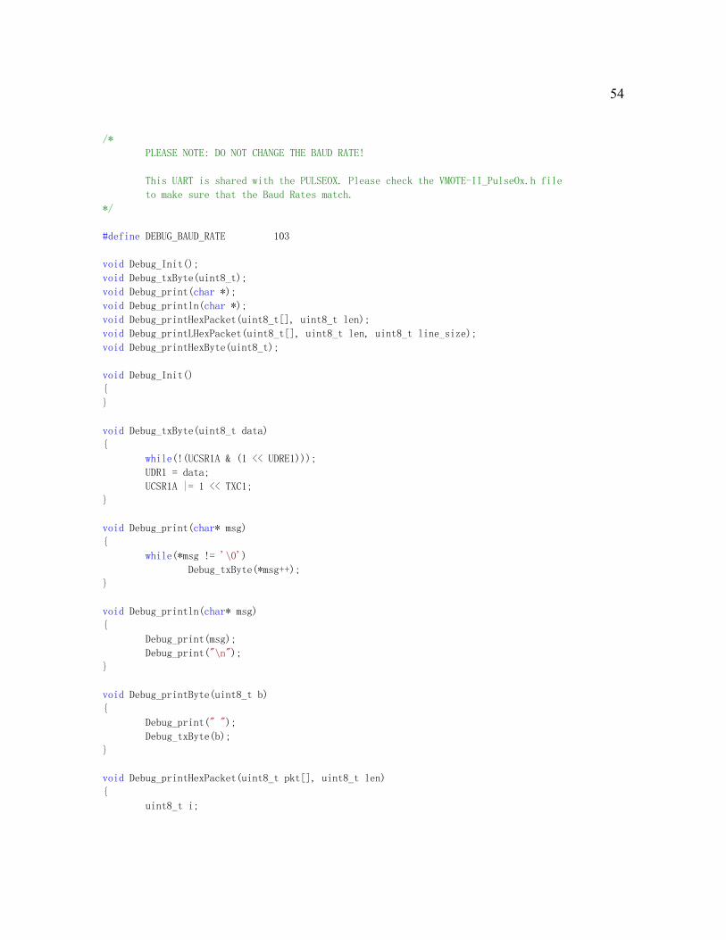
File: VMOTE-II_Debug.h
#ifndef __VMOTE_II_DEBUG_H__
#define __VMOTE_II_DEBUG_H__ 1
54
/*
PLEASE NOTE: DO NOT CHANGE THE BAUD RATE!
This UART is shared with the PULSEOX. Please check the VMOTE-II_PulseOx.h file
to make sure that the Baud Rates match.
*/
#define DEBUG_BAUD_RATE 103
void Debug_Init();
void Debug_txByte(uint8_t);
void Debug_print(char *);
void Debug_println(char *);
void Debug_printHexPacket(uint8_t[], uint8_t len);
void Debug_printLHexPacket(uint8_t[], uint8_t len, uint8_t line_size);
void Debug_printHexByte(uint8_t);
void Debug_Init()
{
}
void Debug_txByte(uint8_t data)
{
while(!(UCSR1A & (1 << UDRE1)));
UDR1 = data;
UCSR1A |= 1 << TXC1;
}
void Debug_print(char* msg)
{
while(*msg != '\0')
Debug_txByte(*msg++);
}
void Debug_println(char* msg)
{
Debug_print(msg);
Debug_print("\n");
}
void Debug_printByte(uint8_t b)
{
Debug_print(" ");
Debug_txByte(b);
}
void Debug_printHexPacket(uint8_t pkt[], uint8_t len)
{
uint8_t i;

55
for(i = 0; i < len; i++)
{
Debug_printHexByte(pkt[i]);
Debug_txByte(' ');
}
}
void Debug_printlnHexPacket(uint8_t pkt[], uint8_t len, uint8_t line_size)
{
uint8_t i, j = 0;
for(i = 0; i < len; i++)
{
Debug_printHexByte(pkt[i]);
Debug_txByte(' ');
if(j >= line_size)
{
Debug_print("\n");
j = 0;
}
else
j++;
}
}
void Debug_printHexByte(uint8_t val)
{
char pseudo[] = {'0', '1', '2', '3',
'4', '5', '6', '7',
'8', '9', 'A', 'B',
'C', 'D', 'E', 'F'};
uint8_t ch = 0x00;
ch = (uint8_t) (val & 0xF0);
ch = (uint8_t) (ch >> 4);
ch = (uint8_t) (ch & 0x0F);
Debug_txByte(pseudo[(uint8_t)ch]);
ch = (uint8_t) (val & 0x0F);
Debug_txByte(pseudo[(uint8_t)ch]);
}
#endif
File: VMOTE-II_CO2.h
#ifndef __VMOTE_II_CO2_H__
#define __VMOTE_II_CO2_H__ 1

56
#include <VMOTE-II_Debug.h>
#define CO2_BAUD_RATE 25
#define CO2_CMD_RESET "<RESET>", 7
#define CO2_CMD_QFF "<QFF>", 5
#define CO2_CMD_D642 "<D642>", 6
#define CO2_CMD_P00 "<P00>", 5
#define CO2_CMD_P01 "<P01>", 5
#define CO2_CMD_P02 "<P02>", 5
void CO2_Init();
void CO2_txByte(uint8_t);
uint8_t CO2_rxByte();
void CO2_sendCommand(char*, uint8_t);
void CO2_Init()
{
UBRR2H = 0; //setting up the
baud rate high bytses
UBRR2L = CO2_BAUD_RATE; //setting up the baud rate low
bytes, 38400
UCSR2A = 1 << U2X2; //double the UART
transmission speed
UCSR2C = (1 << UCSZ21) | (1 << UCSZ20) | (1 << UPM11); // | (0 << USBS1); //recieve
8bit bytes, 1 stop bit
UCSR2C &= ~(1 << UPM10);
UCSR2B = (1 << RXEN2) | (1 << TXEN2); //enable uart1 rx, tx and assocaited interrupts
Debug_println("\t>>> CO2 Communication initialized ..... Baud Rate = 38400 8E1");
Debug_println("\t>>> CO2 Reset Command Sent");
CO2_sendCommand(CO2_CMD_RESET);
while(true)
{
if(CO2_rxByte() != '<')
continue;
else
if(CO2_rxByte() != 'R')
continue;
else
if(CO2_rxByte() != 'E')
continue;
else
if(CO2_rxByte() != 'S')
continue;
else
if(CO2_rxByte() != 'E')

57
continue;
else
if(CO2_rxByte() != 'T')
continue;
else
if(CO2_rxByte() != '>')
continue;
else
break;
}
Debug_println("\t>>> CO2 Command Complete .... CO2 Module Responded");
Debug_println("\t>>> CO2 D002 Command Sent");
while(true)
{
CO2_sendCommand(CO2_CMD_D642);
if(CO2_rxByte() != '<')
continue;
else
if(CO2_rxByte() != 'D')
continue;
else
if(CO2_rxByte() != '6')
continue;
else
if(CO2_rxByte() != '4')
continue;
else
if(CO2_rxByte() != '2')
continue;
else
if(CO2_rxByte() != '>')
continue;
else
break;
}
Debug_println("\t>>> CO2 Command Complete .... CO2 Module Responded");
Debug_println("\t>>> CO2 Q00 Sent");
while(true)
{
CO2_sendCommand(CO2_CMD_QFF);
if(CO2_rxByte() != '<')
continue;
else
if(CO2_rxByte() != 'Q')
continue;
else

58
if(CO2_rxByte() != 'F')
continue;
else
if(CO2_rxByte() != 'F')
continue;
else
if(CO2_rxByte() != '>')
continue;
else
break;
}
Debug_println("\t>>> CO2 Command Complete .... CO2 Module Responded");
Debug_println("\t>>> CO2 Module Initialized .... Ready for Data Commands");
}
void CO2_getRR(uint8_t data[])
{
CO2_sendCommand(CO2_CMD_P00);
while(true)
{
if(CO2_rxByte() != '<')
continue;
else
if(CO2_rxByte() != 'P')
continue;
else
if(CO2_rxByte() != '0')
continue;
else
if(CO2_rxByte() != '0')
continue;
else
{
data[0] = CO2_rxByte();
data[1] = CO2_rxByte();
data[2] = CO2_rxByte();
data[3] = CO2_rxByte();
CO2_rxByte();
if(CO2_rxByte() != '>')
continue;
else
break;
}
}
}
void CO2_getInsCO2(uint8_t data[])
{

59
CO2_sendCommand(CO2_CMD_P01);
while(true)
{
if(CO2_rxByte() != '<')
continue;
else
if(CO2_rxByte() != 'P')
continue;
else
if(CO2_rxByte() != '0')
continue;
else
if(CO2_rxByte() != '1')
continue;
else
{
data[0] = CO2_rxByte();
data[1] = CO2_rxByte();
data[2] = CO2_rxByte();
data[3] = CO2_rxByte();
CO2_rxByte();
if(CO2_rxByte() != '>')
continue;
else
break;
}
}
}
void CO2_getExpCO2(uint8_t data[])
{
CO2_sendCommand(CO2_CMD_P02);
while(true)
{
if(CO2_rxByte() != '<')
continue;
else
if(CO2_rxByte() != 'P')
continue;
else
if(CO2_rxByte() != '0')
continue;
else
if(CO2_rxByte() != '2')
continue;
else
{

60
data[0] = CO2_rxByte();
data[1] = CO2_rxByte();
data[2] = CO2_rxByte();
data[3] = CO2_rxByte();
CO2_rxByte();
if(CO2_rxByte() != '>')
continue;
else
break;
}
}
}
void CO2_getDumy(uint8_t data[])
{
data[0]=0;
data[1]=0;
data[2]=0;
data[3]=0;
}
uint8_t CO2_rxByte()
{
while (!(UCSR2A & (1<<RXC2)) ); // Wait for data to be received
return UDR2; // Get and return
received data from buffer
}
void CO2_txByte(uint8_t data)
{
while(!(UCSR2A & (1 << UDRE2)));
UDR2 = data;
UCSR2A |= 1 << TXC2;
}
void CO2_sendCommand(char* cmd, uint8_t len)
{
uint8_t i;
for(i = 0; i < len; i++)
CO2_txByte(cmd[i]);
}
ISR(USART2_RX_vect){} //Empty Receive Complete Interrupt handler, in case it happens
ISR(USART2_TX_vect){} //Empty Transmit Complete Interrupt handler, in case it happens
#endif

61
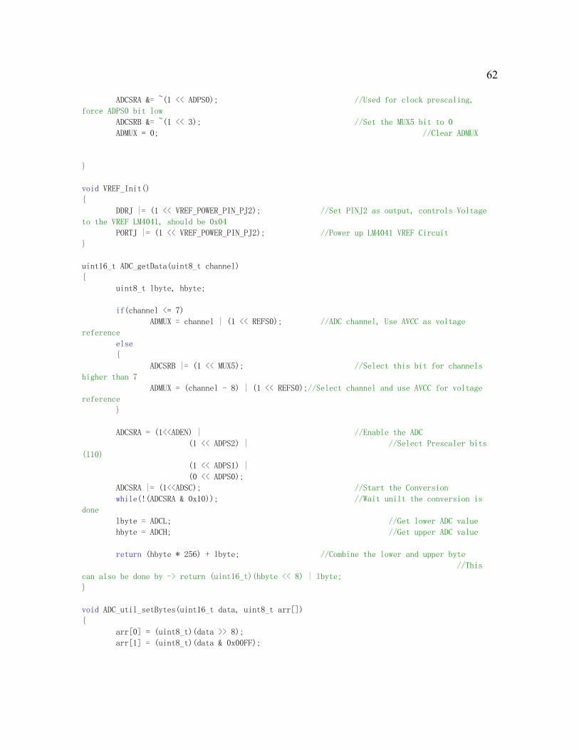
File: VMOTE-II_ADC.h
#ifndef __VMOTE_II_ADC__
#define __VMOTE_II_ADC__ 1
#define CHANNEL_BATT_MON 8
#define CHANNEL_VREF 9
#define CHANNEL_TEMPERATURE 11
#define CHANNEL_GSR 10
#define CHANNEL_ACCEL_YOUT 12
#define CHANNEL_ACCEL_XOUT 13
#define CHANNEL_ACCEL_YFILT 14
#define CHANNEL_ACCEL_XFILT 15
#define VREF_POWER_PIN_PJ2 2
void ADC_Init();
void VREF_Init();
double VCC_getVoltage();
double Battery_getVoltage();
uint16_t ADC_getData(uint8_t);
uint16_t VREF_getData();
uint16_t BATT_MON_getData();
uint16_t Temperature_getData();
uint16_t GSR_getData();
uint16_t ACCEL_XOUT_getData();
uint16_t ACCEL_YOUT_getData();
uint16_t ACCEL_XFILT_getData();
uint16_t ACCEL_YFILE_getData();
void ADC_Init()
{
ADCSRA &= ~(1 << ADEN); //Disable ADC
PRR0 |= (0 << PRADC); //from pg 297 of amtega1281
manual (bottom of page)
DDRF = 0x00; //Select PORTF as ADC
Input
DDRK = 0x00; //Select PORTK as ADC
Input
PORTF = 0xFF; //Activate internal
pullups for PORTF
ADCSRA = (1 << ADIE) | //Enable ADC Complete Interrupt
(1 << ADPS2) | //Select ADC Prescaler
Bits (110)
(1 << ADPS1); //110 means divide clock
by 64
62
ADCSRA &= ~(1 << ADPS0); //Used for clock prescaling,
force ADPS0 bit low
ADCSRB &= ~(1 << 3); //Set the MUX5 bit to 0
ADMUX = 0; //Clear ADMUX
}
void VREF_Init()
{
DDRJ |= (1 << VREF_POWER_PIN_PJ2); //Set PINJ2 as output, controls Voltage
to the VREF LM4041, should be 0x04
PORTJ |= (1 << VREF_POWER_PIN_PJ2); //Power up LM4041 VREF Circuit
}
uint16_t ADC_getData(uint8_t channel)
{
uint8_t lbyte, hbyte;
if(channel <= 7)
ADMUX = channel | (1 << REFS0); //ADC channel, Use AVCC as voltage
reference
else
{
ADCSRB |= (1 << MUX5); //Select this bit for channels
higher than 7
ADMUX = (channel - 8) | (1 << REFS0);//Select channel and use AVCC for voltage
reference
}
ADCSRA = (1<<ADEN) | //Enable the ADC
(1 << ADPS2) | //Select Prescaler bits
(110)
(1 << ADPS1) |
(0 << ADPS0);
ADCSRA |= (1<<ADSC); //Start the Conversion
while(!(ADCSRA & 0x10)); //Wait unilt the conversion is
done
lbyte = ADCL; //Get lower ADC value
hbyte = ADCH; //Get upper ADC value
return (hbyte * 256) + lbyte; //Combine the lower and upper byte
//This
can also be done by -> return (uint16_t)(hbyte << 8) | lbyte;
}
void ADC_util_setBytes(uint16_t data, uint8_t arr[])
{
arr[0] = (uint8_t)(data >> 8);
arr[1] = (uint8_t)(data & 0x00FF);

63
}
uint16_t VREF_getData()
{
return ADC_getData(CHANNEL_VREF);
}
double VCC_getVoltage()
{
//Vcc is taken from a 1.223 Voltage reference, the equation below does the conversion to
give actual voltage
return (double)(((double)1024*1.223)/(double)VREF_getData());
}
uint16_t BATT_MON_getData()
{
return ADC_getData(CHANNEL_BATT_MON);
}
double Battery_getVoltage()
{
//Battery Monitor is a voltage divider (divides by 3), equation below calculates actual
battery level
return ((double)BATT_MON_getData()/1023.0) * VCC_getVoltage() * 3.0;
}
uint16_t Temperature_getData()
{
return ADC_getData(CHANNEL_TEMPERATURE);
}
uint16_t GSR_getData()
{
return ADC_getData(CHANNEL_GSR);
}
uint16_t ACCEL_XOUT_getData()
{
return ADC_getData(CHANNEL_ACCEL_XOUT);
}
uint16_t ACCEL_YOUT_getData()
{
return ADC_getData(CHANNEL_ACCEL_YOUT);
}
uint16_t ACCEL_XFILT_getData()
{
return ADC_getData(CHANNEL_ACCEL_XFILT);
}

64
uint16_t ACCEL_YFILT_getData()
{
return ADC_getData(CHANNEL_ACCEL_YFILT);
}
#endif
File: VMOTE-II_Uart.h
#ifndef __ATMEGA1281_UART_H
#define __ATMEGA1281_UART_H
#include <avr/interrupt.h>
#include <string.h>
#include <stdint.h>
#include <avr/io.h>
void UART0_Init();
void UART0_txByte(uint8_t);
void UART0_sendByte(uint8_t);
void UART0_sendString(const char*);
void UART0_sendPacket(const uint8_t*, const uint8_t);
uint8_t UART0_rxByte();
void SET_UART0_TX_DONE_HANDLER(void (*fpHandler)(void));
void SET_UART0_DATA_RX_HANDLER(void (*fpHandler)(uint8_t));
void UART1_Init();
void UART1_txByte(uint8_t);
void UART1_sendByte(uint8_t);
void UART1_sendString(const char*);
void UART1_sendPacket(const uint8_t*, const uint8_t);
uint8_t UART1_rxByte();
void SET_UART1_TX_DONE_HANDLER(void (*fpHandler)(void));
void SET_UART1_DATA_RX_HANDLER(void (*fpHandler)(uint8_t));
void debugMsg(const char*);
static void (*UART1_Data_RxH)(uint8_t) = NULL;
static void (*UART1_Tx_DoneH)(void) = NULL;
static void (*UART0_Data_RxH)(uint8_t) = NULL;
static void (*UART0_Tx_DoneH)(void) = NULL;
void UART1_Tx(uint8_t data)
{
while(!(UCSR1A & (1<<UDRE1))); //Checking for empty transmit buffer
UDR1 = data;

65
}
uint8_t UART1_Rx(void)
{
/* Wait for data to be received */
while ( !(UCSR1A & (1<<RXC1)) );
/* Get and return received data from buffer */
return UDR1;
}
void UART1_Init()
{
UBRR1H = 0; //setting up the baud rate high bytses
UBRR1L = 16; //setting up the baud rate low bytes, 9600 from pg 234 of datasheet
UCSR1A = 1 << U2X1; //double the UART transmission speed
UCSR1C = (1 << UCSZ11) | (1 << UCSZ10);// | (0 << USBS1); //recieve 8bit bytes, 1
stop bit
UCSR1B = /*(((1 << RXCIE1) | (1 << TXCIE1)) |*/ (1 << RXEN1) | (1 << TXEN1); //enable
uart1 rx, tx and assocaited interrupts
}
void UART0_Init()
{
//look into setting the BAUDRATE to 250kbps to match the radio tranceiver
UBRR0H = 0; //setting up the baud rate high bytses
UBRR0L = 16; //setting up the baud rate low bytes, 57600 from pg 234 of data sheet
UCSR0A = 1 << U2X0; //double the UART transmission speed
UCSR0C = (1 << UCSZ01) | (1 << UCSZ00); //recieve 8bit bytes
UCSR0B = (((1 << RXCIE0) | (1 << TXCIE0)) | (1 << RXEN0)) | (1 << TXEN0); //enable uart0
rx, tx and assocaited interrupts
}
void SET_UART1_TX_DONE_HANDLER(void (*fpHandler)(void))
{
UART1_Tx_DoneH = fpHandler;
}
void SET_UART1_DATA_RX_HANDLER(void (*fpHandler)(uint8_t))
{
UART1_Data_RxH = fpHandler;
}
void SET_UART0_TX_DONE_HANDLER(void (*fpHandler)(void))
{
UART0_Tx_DoneH = fpHandler;
}
void SET_UART0_DATA_RX_HANDLER(void (*fpHandler)(uint8_t))
{
UART0_Data_RxH = fpHandler;

66
}
ISR(USART0_RX_vect)
{
if(UCSR0A & (1 << RXC0) && UART0_Data_RxH != NULL)
(*UART0_Data_RxH)((uint8_t)UDR0);
}
ISR(USART0_TX_vect)
{
if(UART0_Tx_DoneH != NULL)
(*UART0_Tx_DoneH)();
}
/*
ISR(USART1_RX_vect)
{
if(UCSR1A & (1 << RXC1) && UART1_Data_RxH != NULL)
(*UART1_Data_RxH)((uint8_t)UDR1);
}
ISR(USART1_TX_vect)
{
if(UART1_Tx_DoneH != NULL)
(*UART1_Tx_DoneH)();
}
*/
uint8_t UART0_rxByte()
{
/* Wait for data to be received */
while (!(UCSR0A & (1<<RXC0)) );
/* Get and return received data from buffer */
return UDR0;
}
void UART0_txByte(uint8_t data)
{
UART0_sendByte(data);
}
uint8_t UART1_rxByte()
{
/* Wait for data to be received */
while (!(UCSR1A & (1<<RXC1)) );
/* Get and return received data from buffer */
return UDR1;
}
void UART1_txByte(uint8_t data)
{
UART1_sendByte(data);

67
}
void UART0_sendByte(uint8_t data)
{
while(!(UCSR0A & (1 << UDRE0)));
UDR0 = data;
UCSR0A |= 1 << TXC0;
}
void UART1_sendByte(uint8_t data)
{
while(!(UCSR1A & (1 << UDRE1)));
UDR1 = data;
UCSR1A |= 1 << TXC1;
}
void UART0_sendPacket(const uint8_t pkt[], const uint8_t size)
{
uint16_t i;
for(i = 0; i < size; i++)
UART0_sendByte(pkt[i]);
}
void UART1_sendPacket(const uint8_t pkt[], const uint8_t size)
{
uint16_t i;
for(i = 0; i < size; i++)
UART1_sendByte(pkt[i]);
}
void UART0_sendString(const char* msg)
{
while(*msg != '\0')
UART0_sendByte(*msg++);
}
void UART1_sendString(const char* msg)
{
while(*msg != '\0')
UART1_sendByte(*msg++);
}
void debugMsg(const char* str)
{
#ifdef UART0_DEBUG
UART0_sendString(str);
#endif
}

68
#endif
File: VMOTE-II_Timer.h
#include <avr/interrupt.h>
#include <string.h>
#include <stdint.h>
#include <avr/io.h>
enum
{
TOS_I1000PS = 32, TOS_S1000PS = 1,
TOS_I100PS = 40, TOS_S100PS = 2,
TOS_I10PS = 101, TOS_S10PS = 3,
TOS_I1024PS = 0, TOS_S1024PS = 3,
TOS_I512PS = 1, TOS_S512PS = 3,
TOS_I256PS = 3, TOS_S256PS = 3,
TOS_I128PS = 7, TOS_S128PS = 3,
TOS_I64PS = 15, TOS_S64PS = 3,
TOS_I32PS = 31, TOS_S32PS = 3,
TOS_I16PS = 63, TOS_S16PS = 3,
TOS_I8PS = 127, TOS_S8PS = 3,
TOS_I4PS = 255, TOS_S4PS = 3,
TOS_I2PS = 15, TOS_S2PS = 7,
TOS_I1PS = 31, TOS_S1PS = 7,
TOS_I0PS = 0, TOS_S0PS = 0
};
#define FREQ_ATMEGA1281 8000000
#define FREQ_EXT_CRYSTAL 32768 //should be 32768
void (*Clock_FireH)(void) = NULL; //Null function pointer to the clock fire handler
//The enumerations above where designed for a crystal with a freq of FREQ_EXT_CRYSTAL.
//Since we are using the processor freq, we need to normalize that value which is the DOWNSCALER
#define DOWNSCALER (FREQ_ATMEGA1281 / FREQ_EXT_CRYSTAL)
uint8_t oldInterval = 0;
uint8_t oldScale = 0;
uint16_t clockCounts = 0;
static inline void Clock_setRate(char interval, char scale);
inline void SET_CLOCK_FIRE_HANDLER(void (*fpHandler)(void));
static inline void Clock_stop();
static inline void Clock_restart();
static void inline uwait(unsigned long u_sec);
ISR(TIMER2_COMPB_vect)

69
{
if(clockCounts == DOWNSCALER)
{
TCCR2A = 0x02; //use CTC on OCR2A, PG 191, might be 0x1
TCCR2B = oldScale; //clock scaling value, PG 194
TCNT2 = 0; //intial count value
OCR2A = oldInterval; //value to count to
clockCounts = 0;
//check if handler function pointer is initialized
if(Clock_FireH != NULL)
(*Clock_FireH)();
}
else
clockCounts++;
}
static inline void Clock_setRate(char interval, char scale)
{
scale &= 0x7; //set the WGM22 to 0 on bit 3
//Disable all interrupts for Timer2, PG 197
TIMSK2 &= ~(1 << TOIE2);
TIMSK2 &= ~(1 << OCIE2A);
TIMSK2 &= ~(1 << OCIE2B);
ASSR |= 0 << AS2; //use internal io clock, PG 196
//TCCR2A on page 191 of manual
TCCR2A = 0x02; //use CTC on OCR2A, PG 191, might be 0x1
TCCR2B = scale; //clock scaling value, PG 194
TCNT2 = 0; //intial count value
OCR2A = interval; //value to count to
//TIMSK2 |= 1 << OCIE2A; //enable the compare match interrupt for A, could
be B as well, PG 197
TIMSK2 |= 1 << OCIE2B; //enable the compare match interrupt for A, could be B as
well, PG 197
//TIMSK2 |= 1 << TOIE2; //enable the compare match interrupt for A, could be B as
well, PG 197
oldScale = scale;
oldInterval = interval;
}
static inline void Clock_restart()
{
Clock_setRate(oldInterval, oldScale);
}
static inline void Clock_stop()
{
TCCR2B = 0;
}

70
inline void SET_CLOCK_FIRE_HANDLER(void (*fpHandler)(void))
{
Clock_FireH = fpHandler;
}
static void inline uwait(unsigned long u_sec)
{
while (u_sec > 0) {
__asm volatile ("nop");
__asm volatile ("nop");
__asm volatile ("nop");
__asm volatile ("nop");
__asm volatile ("nop");
__asm volatile ("nop");
__asm volatile ("nop");
__asm volatile ("nop");
u_sec--;
}
}
Filer: VMOTE-II_PulseOx.h
#ifndef __VMOTE_II_PULSEOX_H__
#define __VMOTE_II_PULSEOX_H__ 1
void PulseOx_Init();
uint8_t PulseOx_rxByte();
void PulseOx_getPacket(uint8_t pkt[]);
#define PULSEOX_PKT_SIZE 125
#define PULSEOX_BAUD_RATE 103
void PulseOx_Init()
{
UBRR1H = 0; //Setting up the
baud rate high bytses
UBRR1L = PULSEOX_BAUD_RATE; //Setting up the baud rate low
bytes, 9600 from pg 234 of datasheet
UCSR1A = 1 << U2X1; //Double the UART
transmission speed
UCSR1C = (1 << UCSZ11) | (1 << UCSZ10); //Recieve 8bit bytes, 1 stop bit
UCSR1B = (1 << RXEN1) | (1 << TXEN1); //Enable UART1 Receiver
}
uint8_t PulseOx_rxByte()

71
{
while (!(UCSR1A & (1<<RXC1))); //Wait for data to be received
return UDR1; //Get and return received
data from buffer
}
void PulseOx_getPacket(uint8_t pkt[])
{
uint8_t uartdata;
uint8_t PulseOx_dindex = 0;
bool PulseOx_synced = false;
bool PulseOx_checkNextByte = false;
while(true)
{
uartdata = PulseOx_rxByte();
if(!PulseOx_synced)
{
if(!PulseOx_checkNextByte)
{
if (uartdata == 0x1)
PulseOx_checkNextByte = true;
}
else
{
if(uartdata & 1)
{
pkt[0] = 0x01;
pkt[1] = uartdata;
PulseOx_dindex = 2;
PulseOx_synced = true;
}
else
{
if (uartdata == 0x1)
PulseOx_checkNextByte = true;
else
PulseOx_checkNextByte = false;
}
}
}
else
{
if((PulseOx_dindex % 5) == 0)
{
if(uartdata != 0x01)
{
PulseOx_synced = false;
PulseOx_dindex = 0;

72
PulseOx_checkNextByte= false;
}
}
pkt[PulseOx_dindex] = uartdata;
if(PulseOx_dindex == 124)
break;
else
PulseOx_dindex++;
}
}
}
ISR(USART1_RX_vect){} //Empty Receive Complete Interrupt handler, in case it happens
ISR(USART1_TX_vect){} //Empty Transmit Complete Interrupt handler, in case it happens
#endif
File: VMOTE-II_Packet.h
#ifndef __VMOTE_II_PACKET_H__
#define __VMOTE_II_PACKET_H__
#define VMOTE_II_PKT_SIZE 155
#define VMOTE_II_SMALL_PKT_SIZE 46
#define VMOTE_II_FRAME_SYMBOL 0x4D
typedef union
{
struct
{
struct{uint8_t data[125];} PulseOx;
struct{uint8_t data[2];} TEMP;
struct{uint8_t data[2];} GSR;
struct{uint8_t data[2];} BATT;
struct{uint8_t data[2];} VCC;
struct
{
struct{uint8_t data[4];}Ins;
struct{uint8_t data[4];}Exp;
struct{uint8_t data[4];}RR;
}CO2;

73
struct
{
struct{uint8_t data[2];}XFILT;
struct{uint8_t data[2];}YFILT;
struct{uint8_t data[2];}XOUT;
struct{uint8_t data[2];}YOUT;
}ACCEL;
struct{uint8_t data[2];} CRC;
}sensor_data;
uint8_t bytes[VMOTE_II_PKT_SIZE];
}VMOTE_II_DataPacket;
typedef union
{
struct
{
struct{uint8_t data[16];} PulseOx;
struct{uint8_t data[2];} TEMP;
struct{uint8_t data[2];} GSR;
struct{uint8_t data[2];} BATT;
struct{uint8_t data[2];} VCC;
struct
{
struct{uint8_t data[4];}Ins;
struct{uint8_t data[4];}Exp;
struct{uint8_t data[4];}RR;
}CO2;
struct
{
struct{uint8_t data[2];}XFILT;
struct{uint8_t data[2];}YFILT;
struct{uint8_t data[2];}XOUT;
struct{uint8_t data[2];}YOUT;
}ACCEL;
struct{uint8_t data[2];} CRC;
}sensor_data;
uint8_t bytes[VMOTE_II_SMALL_PKT_SIZE];
}VMOTE_II_SMALL_DataPacket;
void zipdata(VMOTE_II_DataPacket vmote_data, VMOTE_II_SMALL_DataPacket *small_vmote_data)
{
(*small_vmote_data).sensor_data.PulseOx.data[0]=vmote_data.sensor_data.PulseOx.data[0];
(*small_vmote_data).sensor_data.PulseOx.data[1]=vmote_data.sensor_data.PulseOx.data[1];
(*small_vmote_data).sensor_data.PulseOx.data[2]=vmote_data.sensor_data.PulseOx.data[3];

74
(*small_vmote_data).sensor_data.PulseOx.data[3]=vmote_data.sensor_data.PulseOx.data[8];
(*small_vmote_data).sensor_data.PulseOx.data[4]=vmote_data.sensor_data.PulseOx.data[13];
(*small_vmote_data).sensor_data.PulseOx.data[5]=vmote_data.sensor_data.PulseOx.data[43];
(*small_vmote_data).sensor_data.PulseOx.data[6]=vmote_data.sensor_data.PulseOx.data[48];
(*small_vmote_data).sensor_data.PulseOx.data[7]=vmote_data.sensor_data.PulseOx.data[53];
(*small_vmote_data).sensor_data.PulseOx.data[8]=vmote_data.sensor_data.PulseOx.data[68];
(*small_vmote_data).sensor_data.PulseOx.data[9]=vmote_data.sensor_data.PulseOx.data[73];
(*small_vmote_data).sensor_data.PulseOx.data[10]=vmote_data.sensor_data.PulseOx.data[78];
(*small_vmote_data).sensor_data.PulseOx.data[11]=vmote_data.sensor_data.PulseOx.data[83];
(*small_vmote_data).sensor_data.PulseOx.data[12]=vmote_data.sensor_data.PulseOx.data[98];
(*small_vmote_data).sensor_data.PulseOx.data[13]=vmote_data.sensor_data.PulseOx.data[103];
(*small_vmote_data).sensor_data.PulseOx.data[14]=vmote_data.sensor_data.PulseOx.data[108];
(*small_vmote_data).sensor_data.PulseOx.data[15]=vmote_data.sensor_data.PulseOx.data[113];
memcpy(&((*small_vmote_data).sensor_data.TEMP), &(vmote_data.sensor_data.TEMP),
sizeof(vmote_data.sensor_data.TEMP));
memcpy(&((*small_vmote_data).sensor_data.GSR), &(vmote_data.sensor_data.GSR),
sizeof(vmote_data.sensor_data.GSR));
memcpy(&((*small_vmote_data).sensor_data.BATT), &(vmote_data.sensor_data.BATT),
sizeof(vmote_data.sensor_data.BATT));
memcpy(&((*small_vmote_data).sensor_data.VCC), &(vmote_data.sensor_data.VCC),
sizeof(vmote_data.sensor_data.VCC));
memcpy(&((*small_vmote_data).sensor_data.CO2), &(vmote_data.sensor_data.CO2),
sizeof(vmote_data.sensor_data.CO2));
memcpy(&((*small_vmote_data).sensor_data.ACCEL), &(vmote_data.sensor_data.ACCEL),
sizeof(vmote_data.sensor_data.ACCEL));
memcpy(&((*small_vmote_data).sensor_data.CRC), &(vmote_data.sensor_data.CRC),
sizeof(vmote_data.sensor_data.CRC));
}
#endif
File: VMOTE-II_Leds.h
#ifndef __CMOTE_LEDS_H__
#define __CMOTE_LEDS_H__ 1
#define LED_COUNT 5
#define LED_PORT PORTA
#define LED_DDR DDRA
#define LED_RED 0
#define LED_ORANGE 2
#define LED_BLUE 3
#define LED_GREEN 1
#define LED_YELLOW 4

75
void Leds_Init();
void Leds_off();
void Leds_on();
void Led_off(uint8_t led);
void Led_on(uint8_t led);
void Led_toggle(uint8_t led);
void Led_redOff();
void Led_redOn();
void Led_redToggle();
void Led_orangeOff();
void Led_orangeOn();
void Led_orangeToggle();
void Led_blueOff();
void Led_blueOn();
void Led_blueToggle();
void Led_greenOff();
void Led_greenOn();
void Led_greenToggle();
void Led_yellowOff();
void Led_yellowOn();
void Led_yellowToggle();
/*** Generic Led Functions ***/
void Leds_Init()
{
LED_DDR |= (1 << LED_RED) |
(1 << LED_ORANGE) |
(1 << LED_BLUE) |
(1 << LED_GREEN) |
(1 << LED_YELLOW);
Leds_off();
}
void Led_off(uint8_t x)
{
if(x < LED_COUNT)
LED_PORT |= (1 << x);
}
void Led_on(uint8_t x)
{
if(x < LED_COUNT)
LED_PORT &= ~(1 << x);
}
void Led_toggle(uint8_t x)
{
if(x < LED_COUNT)

76
LED_PORT ^= (1 << x);
}
void Leds_off()
{
LED_PORT |= (1 << LED_RED) |
(1 << LED_ORANGE) |
(1 << LED_BLUE) |
(1 << LED_GREEN) |
(1 << LED_YELLOW);
}
void Leds_on()
{
LED_PORT &= ~(1 << LED_RED) &
~(1 << LED_ORANGE) &
~(1 << LED_BLUE) &
~(1 << LED_GREEN) &
~(1 << LED_YELLOW);
}
/*** RED LED ***/
void Led_redOn()
{
Led_on(LED_RED);
}
void Led_redOff()
{
Led_off(LED_RED);
}
void Led_redToggle()
{
Led_toggle(LED_RED);
}
/*** ORANGE LED ***/
void Led_orangeOn()
{
Led_on(LED_ORANGE);
}
void Led_orangeOff()
{
Led_off(LED_ORANGE);
}

77
void Led_orangeToggle()
{
Led_toggle(LED_ORANGE);
}
/*** BLUE ***/
void Led_blueOn()
{
Led_on(LED_BLUE);
}
void Led_blueOff()
{
Led_off(LED_BLUE);
}
void Led_blueToggle()
{
Led_toggle(LED_BLUE);
}
/*** GREEn ***/
void Led_greenOn()
{
Led_on(LED_GREEN);
}
void Led_greenOff()
{
Led_off(LED_GREEN);
}
void Led_greenToggle()
{
Led_toggle(LED_GREEN);
}
/*** YELLOW ***/
void Led_yellowOn()
{
Led_on(LED_YELLOW);
}
void Led_yellowOff()
{
Led_off(LED_YELLOW);
}

78
void Led_yellowToggle()
{
Led_toggle(LED_YELLOW);
}
#endif
File: VMoteServer.c
#include <string.h>
#include <stdint.h>
#include <avr/io.h>
#include <avr/wdt.h>
#include <stdbool.h>
#include <ieee_const.h>
#include <wpan_mac.h>
#define RF_BAND BAND_2400
#include <VMOTE-II_Uart.h>
#include <VMOTE-II_Leds.h>
#include <VMOTE-II_Debug.h>
typedef enum
{
IDLE,
SCANNING,
RESET,
SETTING_ADDRESS,
STARTING_PAN,
SETTING_PERMISSION,
WAITING_FOR_CONNECTIONS,
CONNECTED,
CONNECT_FAILED
}DEVICE_STATE;
#define DEFAULT_CHANNEL 0x0D
#define DEFAULT_PANID 0xDEAF
#define SCANDURATION 0x03
uint16_t uSHORT_ADDRESS = 0xACE;
DEVICE_STATE state;
bool permit = true;
bool scandone = false;
void reset_mac()

79
{
Debug_println("RESETING MAC LAYER\n");
wpan_mlme_reset_request(true);
state = RESET;
}
void scanNetwork()
{
Debug_println("SCANNING NETWORK\n");
state = SCANNING;
uint32_t channelMask = 1UL;
//Generate channel mask as defined in MLME_SCAN_request.
channelMask = channelMask << DEFAULT_CHANNEL;
//Issue an active scan on the given channel for a define period.
wpan_mlme_scan_request(MLME_SCAN_TYPE_ACTIVE, channelMask, SCANDURATION);
}
void setMacShortAddress()
{
Debug_println("SETTING ADDRESS\n");
state = SETTING_ADDRESS;
wpan_mlme_set_request(macShortAddress, &uSHORT_ADDRESS, sizeof(uSHORT_ADDRESS));
}
void startPan()
{
Debug_println("STARTING PAN\n");
state = STARTING_PAN;
wpan_mlme_start_request(DEFAULT_PANID, DEFAULT_CHANNEL, 0x0F, 0x0F, true, false, false,
false);
}
void setPermit()
{
Debug_println("SETTING ASSOCIATION PERMISSIONS\n");
state = SETTING_PERMISSION;
wpan_mlme_set_request(macAssociationPermit, &permit, sizeof(permit));
}
void Init()
{
wdt_disable();
wpan_init();
sei();
state = IDLE;
UART0_Init();
UART1_Init();
Leds_Init();

80
Leds_off();
Debug_println("SYSTEM INITIALIZATION DONE\n");
}
int main()
{
Init();
//reset_mac();
//while(state == RESET);
while(true)
{
while(wpan_task());
if(state == IDLE)
scanNetwork();
else if(state == SCANNING)
Leds_on();
else if(state == WAITING_FOR_CONNECTIONS)
{
Leds_off();
Led_yellowOn();
//Leds_greenToggle();
}
else if(state == CONNECTED)
{
Led_redOff();
Led_yellowOff();
Led_blueOn();
}
else if(state == CONNECT_FAILED)
{
Leds_off();
Led_redOn();
}
else
Leds_off();
}
}
void usr_mlme_reset_conf(uint8_t status)
{
Debug_println("MAC LAYER RESET COMPLETED\n");
state = IDLE;
}
void usr_mlme_scan_conf( uint8_t status, uint8_t ScanType, uint32_t UnscannedChannels,
uint8_t ResultListSize, uint8_t *data, uint8_t
data_length )

81
{
if(status == MAC_NO_BEACON)
setMacShortAddress();
else
{
Debug_println("*** SCAN FAILED...\n");
scanNetwork();
}
}
void usr_mlme_set_conf( uint8_t status, uint8_t PIBAttribute )
{
switch(state)
{
case SETTING_ADDRESS:
if(status == MAC_SUCCESS)
startPan();
else
{
Debug_println("*** MAC ADDRESS SET FAILED....\n");
setMacShortAddress();
}
break;
case SETTING_PERMISSION:
if(status == MAC_SUCCESS)
{
Debug_println("WAITING FOR CLIENT CONNECTIONS\n");
state = WAITING_FOR_CONNECTIONS;
}
else
{
Debug_println("*** SETTING PERMISSION FAILED...\n");
setPermit();
}
break;
case STARTING_PAN:
case IDLE:
case SCANNING:
case RESET:
case WAITING_FOR_CONNECTIONS:
case CONNECTED:
case CONNECT_FAILED:
break;
}
}
void usr_mlme_start_conf(uint8_t status)
{
if(status == MAC_SUCCESS)
{

82
Debug_println("**** PAN STARTED ....\n");
setPermit();
}
else
{
Debug_println("**** STARTING PAN FAILED\n");
startPan();
}
}
void usr_mlme_associate_ind(uint64_t DeviceAddress, uint8_t CapabilityInformation, uint8_t
SecurityUse, uint8_t ACLEntry)
{
//Generate response.
Debug_println("*** DEVICE TRYING TO ASSOCIATE...\n");
wpan_mlme_associate_response(DeviceAddress, 0x0001, ASSOCIATION_SUCCESSFUL, false);
}
void usr_mlme_comm_status_ind(wpan_commstatus_addr_t *pAddrInfo, uint8_t status)
{
if(status == MAC_SUCCESS)
{
Debug_println("*** CLIENT CONNECTED\n");
state = CONNECTED;
}
else
{
Debug_println("**** CLIENT CONNECTION FAILED\n");
state = CONNECT_FAILED;
}
}
void usr_mcps_data_conf( uint8_t msduHandle, uint8_t status )
{
//Used to check if a message transmitted successfully over radio
}
void sendHexString(uint8_t in)
{
uint8_t ch = 0x00;
char pseudo[] = {'0', '1', '2','3', '4', '5', '6', '7',
'8', '9', 'A', 'B', 'C', 'D', 'E','F'};
ch = (uint8_t) (in & 0xF0); // Strip off high nibble
ch = (uint8_t) (ch >> 4);
// shift the bits down
ch = (uint8_t) (ch & 0x0F);
// must do this is high order bit is on!
UART1_sendByte(pseudo[ (int) ch]); // convert the nibble to a String Character

83
ch = (uint8_t) (in & 0x0F); // Strip off low nibble
UART1_sendByte(pseudo[ (int) ch]); // convert the nibble to a String Character
}
void usr_mcps_data_ind(wpan_mcpsdata_addr_t *addrInfo, uint8_t mpduLinkQuality,
uint8_t SecurityUse, uint8_t ACLEntry, uint8_t msduLength, uint8_t *msdu)
{
Debug_println("**** DATA RECEIVED FROM CLIENT...LQI => ");
sendHexString(mpduLinkQuality);
Debug_println("\tDATA MSG =>\t");
UART0_sendPacket(msdu, msduLength);
Debug_println("\n");
Debug_println("\n");
Led_greenToggle();
}

84
C Source Code of GUI Program
File: DataViewForm.cs
using System;
using System.Collections.Generic;
using System.ComponentModel;
using System.Data;
using System.Drawing;
using System.Linq;
using System.Text;
using System.Windows.Forms;
namespace VPackIII
{
public partial class DataViewForm : Form
{
public DataViewForm()
{
InitializeComponent();
}
public void resetAllLabels()
{
label4.Text = "";
label5.Text = "";
label6.Text = "";
label9.Text = "";
label10.Text = "";
label26.Text = "";
label27.Text = "";
label28.Text = "";
label29.Text = "";
label30.Text = "";
label31.Text = "";
label32.Text = "";
label33.Text = "";
label34.Text = "";
label35.Text = "";
label36.Text = "";
label37.Text = "";
label38.Text = "";
label39.Text = "";
label40.Text = "";
}
public void setETCO2(string s)
{
label4.Text = s;

85
}
public void setRR(string s)
{
label5.Text = s;
}
public void setINSCO2(string s)
{
label6.Text = s;
}
public void setAccelXOUT(string s)
{
label9.Text = s;
}
public void setAccelYOUT(string s)
{
label10.Text = s;
}
public void setTemperature(string s)
{
label39.Text = s;
}
public void setGSR(string s)
{
label40.Text = s;
}
public void setHR(string s)
{
label26.Text = s;
}
public void setSPO2D(string s)
{
label27.Text = s;
}
public void setSPO2FAST(string s)
{
label28.Text = s;
}
public void setESPO2D(string s)
{
label29.Text = s;

86
}
public void setEHRD(string s)
{
label30.Text = s;
}
public void setBlood(string s)
{
label31.Text = s;
}
public void setSPO2BB(string s)
{
label32.Text = s;
}
public void setESPO2(string s)
{
label33.Text = s;
}
public void setHRD(string s)
{
label34.Text = s;
}
public void setEHR(string s)
{
label35.Text = s;
}
public void setPerfusion(Color c)
{
label36.BackColor = c;
}
public void setDeviceStatus(string s)
{
label37.Text = s;
}
public void setDataStatus(string s)
{
label38.Text = s;
}
public void resetSPO2Labels()
{
label26.Text = "---";

87
label27.Text = "---";
label28.Text = "---";
label29.Text = "---";
label30.Text = "---";
label31.Text = "---";
label32.Text = "---";
label33.Text = "---";
label34.Text = "---";
label35.Text = "---";
label36.BackColor = Color.White;
}
}
}
File: DBManager.cs
using System;
using System.Collections.Generic;
using System.Linq;
using System.Text;
using MySql.Data.MySqlClient;
using System.Windows.Forms;
namespace VPackIII
{
class DBManager
{
private string server;
private string uid;
private string pwd;
private string database;
private MySqlConnection conn;
private MySqlCommand cmd;
private int count = 0;
public DBManager(string server, string uid, string pwd, string database)
{
this.server = server;
this.uid = uid;
this.pwd = pwd;
this.database = database;
}
public void dbManagerInit(string server, string uid, string pwd, string database)
{
this.server = server;

88
this.uid = uid;
this.pwd = pwd;
this.database = database;
}
public int getCount()
{
return count;
}
public void dispose()
{
conn.Dispose();
}
public void writePacket(VPackIII_Packet pkt)
{
string connStr = String.Format("server={0};uid={1};pwd={2};database={3}", server, uid,
pwd, database);
conn = new MySqlConnection(connStr);
try
{
conn.Open();
string sql = "INSERT INTO data_table (RR, ETCO2, INSCO2, TEMP, GSR, HR, BO, SPO2D,
SPO2BB, SPO2FAST, ESPO2,"
+ "ESPO2D, HRD, EHRD, EHR, DATE_1) VALUES ("
+ "'" + pkt.getRR()
+ "','" + pkt.getExpCO2()
+ "','" + pkt.getINSCO2()
+ "','" + pkt.getTemperatureC()
+ "','" + pkt.getGSR()
+ "','" + pkt.getHeartRate()
+ "','" + pkt.getBloodOxidization()
+ "','" + pkt.getSPO2_D()
+ "','" + pkt.getSPO2_B_B()
+ "','" + pkt.getSPO2_Fast()
+ "','" + pkt.getE_SPO2()
+ "','" + pkt.getE_SPO2_D()
+ "','" + pkt.getHR_D()
+ "','" + pkt.getE_HR_D()
+ "','" + pkt.getE_HR()
+ "','" + DateTime.Now
+ "');";
cmd = new MySqlCommand(sql, conn);
cmd.ExecuteNonQuery();
conn.Close();

89
count++;
}
catch (Exception ex)
{
MessageBox.Show("Exception: " + ex.Message);
}
}
}
}
File: ImageViewForm.cs
using System;
using System.Collections.Generic;
using System.ComponentModel;
using System.Data;
using System.Drawing;
using System.Linq;
using System.Text;
using System.Windows.Forms;
using System.Threading;
namespace VPackIII
{
public partial class ImageViewForm : Form
{
private int lastValue;
private int current_X;
PointF[] pointArray;
Bitmap bMap;
Graphics gph;
public ImageViewForm()
{
InitializeComponent();
lastValue = 0;
current_X = 0;
pointArray = new PointF[81];
bMap = new Bitmap(800, 400);
gph = Graphics.FromImage(bMap);
Bitmap bMap2 = new Bitmap(40, 400);
Graphics gph2 = Graphics.FromImage(bMap2);
gph2.Clear(Color.Black);
for (int i = 1; i <= 20; i++)
{

90
gph2.DrawLine(Pens.White, 30, i * 20, 40, i * 20);
gph2.DrawString((200 - (i * 10)).ToString(), new Font("Microsoft Sans Serif", 8),
Brushes.White, new PointF(5, (i * 20) - 12));
}
gph2.DrawLine(Pens.White, 39, 0, 39, 400);
this.pictureBox2.Image = bMap2;
init();
}
public void init()
{
gph.Clear(Color.Black);
for (int i = 1; i <= 19; i++)
{
gph.DrawLine(Pens.Gray, 0, i * 20, 800, i * 20);
}
for (int i = 1; i <= 79; i++)
{
gph.DrawLine(Pens.Gray, i * 10, 0, i * 10, 400);
}
gph.DrawLine(Pens.White, 0, 200, 800, 200);
this.pictureBox1.Image = bMap;
}
public void draw(int value)
{
if (lastValue == 0)
{
lastValue = (200 - value) * 2;
}
else
{
value = (200 - value) * 2;
if (current_X <= 790)
{
PointF p1 = new PointF(current_X, lastValue);
pointArray[current_X / 10] = p1;
current_X += 10;
PointF p2 = new PointF(current_X, value);
if (current_X == 800)
{
pointArray[current_X / 10] = p2;
}
gph.DrawLine(Pens.LawnGreen, p1, p2);
lastValue = value;
}
else
{
for (int i = 0; i <= 79; i++)
{

91
pointArray[i].Y = pointArray[i + 1].Y;
}
pointArray[80] = new PointF(800, value);
redraw();
}
}
this.pictureBox1.Image = bMap;
}
public void redraw()
{
init();
for (int i = 0; i <= 79; i++)
{
gph.DrawLine(Pens.LawnGreen, pointArray[i], pointArray[i+1]);
}
//gph.DrawString((200 - (pointArray[80].Y / 2)).ToString(), new Font("Microsoft Sans
Serif", 14), Brushes.LawnGreen, new PointF(750, 50));
//Console.WriteLine("--");
}
/*public void run(int value)
{
int iseed = 10;
Random r = new Random(iseed);
for (int i = 0; i <= 500; i++)
{
int tmp = 80 + r.Next(-20, 20);
draw(tmp);
Thread.Sleep(100);
}
}
*/
}
}
File: MainForm.cs
using System;
using System.Collections.Generic;
using System.ComponentModel;
using System.Data;
using System.Drawing;
using System.Linq;
using System.Text;
using System.Windows.Forms;
using System.Threading;

92
namespace VPackIII
{
public partial class MainForm : Form, UpdateFormInterface
{
DataViewForm dataViewForm;
ImageViewForm imageViewForm;
PacketManager pktManager;
RS232Manager rs232Manager;
DBManager dbManager;
SocketPipe pipe;
Thread socketThread;
int pktsRxed = 0;
public MainForm()
{
InitializeComponent();
dataViewForm = new DataViewForm();
imageViewForm = new ImageViewForm();
pktManager = new PacketManager(this);
//dbManager = new DBManager("128.172.192.81", "root", "mitac4vcu", "sensor_data");
pipe = new SocketPipe();
rs232Manager = new RS232Manager(pktManager);
socketThread = null;
setStartCOMControl();
resetAllLabels();
}
public void MainForm_Closing(object sender, System.EventArgs cArgs)
{
try
{
//dbManager.dispose();
pipe.disconnect();
}
catch (Exception e)
{
}
Application.Exit();
}
public void about(object sender, System.EventArgs args)
{
93
MessageBox.Show("VPackIII version 1.0");
}
public void setStartCOMControl()
{
button2.Enabled = true;
button3.Enabled = false;
}
public void setStopCOMControl()
{
button2.Enabled = false;
button3.Enabled = true;
}
public void enableCOMControl()
{
button2.Enabled = true;
button3.Enabled = true;
}
public void disableCOMControl()
{
button2.Enabled = false;
button3.Enabled = false;
}
private void resetAllLabels()
{
dataViewForm.resetAllLabels();
label5.Text = "";
label6.Text = "";
label9.Text = "";
}
public Control getFormControl()
{
return this;
}
public void updateForm(VPackIII_Packet pkt)
{
if (pkt.getLength() != VPackIII_Packet_Constants.PACKET_LENGTH)
{
this.richTextBox1.AppendText("! Error: Invalid length packet length!\n");
}
else
{
try
94
{
this.richTextBox1.AppendText("# Get packet!\n");
if (!textBox2.Enabled)
{
if (pipe.isConnected())
{
pipe.sendByte(pkt.data);
this.richTextBox1.AppendText("# Packet is sent!\n");
}
}
dataViewForm.setTemperature(String.Format("{0:F2}", pkt.getTemperatureC()) +
" C"
+ " [" + String.Format("{0:F2}", pkt.getTemperatureF()) + "
F]");
dataViewForm.setGSR(String.Format("{0:F4}", pkt.getGSR()) + " uS");
dataViewForm.setAccelXOUT("" + pkt.getAccel_XFILT());
dataViewForm.setAccelYOUT("" + pkt.getAccel_YFILT());
dataViewForm.setINSCO2(String.Format("{0:F2}", pkt.getINSCO2()) + " mmHg");
dataViewForm.setETCO2(String.Format("{0:F2}", pkt.getExpCO2()) + " mmHg");
dataViewForm.setRR(String.Format("{0:F2}", pkt.getRR()) + " BPM");
label5.Text = String.Format("{0:F2}", pkt.getVCC()) + " V";
label6.Text = String.Format("{0:F2}", pkt.getBatteryVoltage()) + " V";
dataViewForm.setDeviceStatus(pkt.getSPO2Status());
dataViewForm.setDataStatus(pkt.getSPO2DataStatus());
if (pkt.isSPO2Connected() && pkt.isSPO2DataValid())
{
if (pkt.getHeartRate() != -1 && pkt.getBloodOxidization() != -1 &&
pkt.getE_HR_D() != -1)
{
dataViewForm.setHR("" + pkt.getHeartRate());
imageViewForm.draw((int)pkt.getHeartRate());
dataViewForm.setBlood("" + pkt.getBloodOxidization());
dataViewForm.setESPO2("" + pkt.getE_SPO2());
dataViewForm.setESPO2D("" + pkt.getE_SPO2_D());
dataViewForm.setSPO2BB("" + pkt.getSPO2_B_B());
dataViewForm.setSPO2FAST("" + pkt.getSPO2_Fast());
dataViewForm.setSPO2D("" + pkt.getSPO2_D());
dataViewForm.setHRD("" + pkt.getHR_D());

95
dataViewForm.setEHRD("" + pkt.getE_HR_D());
dataViewForm.setEHR("" + pkt.getE_HR());
dataViewForm.setPerfusion(pkt.getPerfusionColor());
}
}
else
{
dataViewForm.resetSPO2Labels();
}
//dbManager.writePacket(pkt);
updateLastPktRxStatus();
updatePktRxStatus();
}
catch (Exception e)
{
this.richTextBox1.AppendText("! Message: " + e.Message + "\n"
+ "! Stack trace: " + e.StackTrace + "\n");
}
}
}
private void updateLastPktRxStatus()
{
label7.Text = "Last packet received at: " + DateTime.Now;
}
private void updatePktRxStatus()
{
pktsRxed++;
label9.Text = "" + pktsRxed;
}
bool button1_check = false;
private void button1_Click(object sender, EventArgs e)
{
if (!button1_check)
{
this.richTextBox1.AppendText("# Showing numerical data window...\n");
this.dataViewForm.Show();
button1_check = true;
button1.Text = "OFF";
}
else
{

96
this.richTextBox1.AppendText("# Numerical data window is closed!\n");
this.dataViewForm.Hide();
button1_check = false;
button1.Text = "ON";
}
}
bool button6_check = false;
private void button6_Click(object sender, EventArgs e)
{
if (!button6_check)
{
this.richTextBox1.AppendText("# Showing heart rate graphic window...\n");
this.imageViewForm.Show();
button6_check = true;
button6.Text = "OFF";
//Thread t = new Thread(this.imageViewForm.run);
//t.Start();
}
else
{
this.richTextBox1.AppendText("# Heart rate graphic window is closed!\n");
this.imageViewForm.Hide();
button6_check = false;
button6.Text = "ON";
}
}
private void button2_Click(object sender, EventArgs e)
{
this.richTextBox1.AppendText("# Starting application...\n");
rs232Manager.setCOMPort("COM" + textBox1.Text);
this.richTextBox1.AppendText("# Connecting to specified COM port...\n");
rs232Manager.connect();
if (!rs232Manager.isConnected())
{
this.richTextBox1.AppendText("# COM port is in use or not valid!\n");
}
else
{
this.richTextBox1.AppendText("# COM port is connected!\n");
setStopCOMControl();
textBox1.Enabled = false;
label2.Text = "Connected";
if (!textBox2.Enabled)
{
this.richTextBox1.AppendText("# Initiating socket connection...\n");
pipe.init(Convert.ToInt16(textBox2.Text), textBox3.Text);
this.richTextBox1.AppendText("# Starting new thread for socket
connection...\n");

97
socketThread = new Thread(pipe.connnect);
socketThread.Start();
this.richTextBox1.AppendText("# Thread for socket connection started!\n");
}
resetAllLabels();
}
}
private void button3_Click(object sender, EventArgs e)
{
try
{
this.richTextBox1.AppendText("# Disconnecting from the COM port...\n");
rs232Manager.disconnect();
this.richTextBox1.AppendText("# COM port is disconnected!\n");
setStartCOMControl();
textBox1.Enabled = true;
label2.Text = "No Connection";
/*
if(socketThread != null)
{
this.richTextBox1.AppendText("# Dropping the socket connection...\n");
socketThread.Abort();
this.richTextBox1.AppendText("# Thread for socket connection stopped!\n");
}
*/
textBox2.Enabled = true;
textBox3.Enabled = true;
}
catch (Exception ex)
{
this.richTextBox1.AppendText("! Message: " + ex.Message + "\n"
+ "! Stack trace: " + ex.StackTrace + "\n");
}
}
private void button4_Click(object sender, EventArgs e)
{
this.richTextBox1.AppendText("# Port and IP information are saved!\n");
textBox2.Enabled = false;
textBox3.Enabled = false;
}
private void button5_Click(object sender, EventArgs e)
{
this.richTextBox1.AppendText("# Port and IP information are resetted!\n");
textBox2.Enabled = true;
textBox3.Enabled = true;
}
}

98
}
File: PacketManager.cs
using System;
using System.Collections.Generic;
using System.Linq;
using System.Text;
namespace VPackIII
{
public class PacketManager
{
UpdateFormInterface f;
byte[] packet = new byte[VPackIII_Packet_Constants.PACKET_LENGTH];
byte LENGTH_BYTE = VPackIII_Packet_Constants.LENGTH_MARKER;
byte FRAME_DELIM = VPackIII_Packet_Constants.FRAME_DELIM;
int LAST_INDEX = VPackIII_Packet_Constants.PACKET_LENGTH - 1;
int byteIndex = 0;
bool SYNC_DONE = false;
byte lastByte = 0x0;
byte last2Byte = 0x0;
delegate void UpdateForm(VPackIII_Packet packet);
public PacketManager(UpdateFormInterface f)
{
this.f = f;
}
public void reset()
{
last2Byte = 0x0;
lastByte = 0x0;
SYNC_DONE = false;
byteIndex = 0;
}
public void OnRxChar(byte input)
{
if (!SYNC_DONE)
{
if (lastByte == LENGTH_BYTE && last2Byte == FRAME_DELIM)
{
SYNC_DONE = true;
packet[0] = input;
byteIndex = 1;
}

99
else
{
last2Byte = lastByte;
}
}
else
{
if (byteIndex == 1 && !((input & 0x81) == 0x81))
{
SYNC_DONE = false;
byteIndex = 0;
last2Byte = 0x0;
}
packet[byteIndex] = input;
if (byteIndex == LAST_INDEX)
{
SYNC_DONE = false;
byteIndex = 0;
last2Byte = 0x0;
UpdateForm updateForm = new UpdateForm(f.updateForm);
f.getFormControl().Invoke(updateForm, new Object[] { new
VPackIII_Packet(packet) });
}
else
byteIndex++;
}
lastByte = input;
}
}
}
File: Program.cs
using System;
using System.Collections.Generic;
using System.Linq;
using System.Windows.Forms;
namespace VPackIII
{
static class Program
{
/// <summary>
/// The main entry point for the application.
/// </summary>
[STAThread]

100
static void Main()
{
Application.EnableVisualStyles();
Application.SetCompatibleTextRenderingDefault(false);
Application.Run(new MainForm());
}
}
}
File: RS232Manager.cs
using System;
using System.Collections.Generic;
using System.Linq;
using System.Text;
using System.IO.Ports;
using System.Threading;
namespace VPackIII
{
public class RS232Manager
{
Thread readThread;
PacketManager pktManager;
SerialPort sPort;
string port;
bool readData = false;
delegate void OnRxChar(byte data);
public RS232Manager(PacketManager pktManager)
{
this.pktManager = pktManager;
sPort = null;
}
public void setCOMPort(string port)
{
this.port = port;
}
public string getName()
{
return "COM Port";
}
public void connect()
{

101
try
{
sPort = new SerialPort(port, 57600);
sPort.Open();
if (sPort.IsOpen)
{
readData = true;
readThread = new Thread(read);
readThread.Start();
}
}
catch (Exception e)
{
}
}
public bool isConnected()
{
return sPort.IsOpen;
}
public void disconnect()
{
sPort.Close();
readData = false;
try
{
readThread.Abort();
}
catch (Exception e)
{
}
}
private void read()
{
OnRxChar rx = new OnRxChar(pktManager.OnRxChar);
while (readData)
{
try
{
rx((byte)sPort.ReadByte());
}
catch (Exception e)
{
}
}
}
}
}

102
File: SocketPipe.cs
using System;
using System.Collections.Generic;
using System.Linq;
using System.Text;
using System.IO;
using System.Net;
using System.Net.Sockets;
namespace VPackIII
{
public class SocketPipe
{
private int port;
private string host;
IPAddress ip;
IPEndPoint ipe;
Socket client;
public SocketPipe()
{
}
public void init(int port, string host)
{
this.port = port;
this.host = host;
ip = IPAddress.Parse(host);
ipe = new IPEndPoint(ip, port);
try
{
client = new Socket(AddressFamily.InterNetwork, SocketType.Stream,
ProtocolType.Tcp);
}
catch (Exception e)
{
Console.WriteLine(e);
}
}
public void connnect()
{
client.Connect(ipe);

103
}
public bool isConnected()
{
if (client.Connected)
return true;
else
return false;
}
public void sendByte(byte[] b)
{
client.Send(b);
}
public void disconnect()
{
client.Close();
}
}
}
File: UpdateFormInterface.cs
using System;
using System.Collections.Generic;
using System.Linq;
using System.Text;
using System.Windows.Forms;
namespace VPackIII
{
public interface UpdateFormInterface
{
void updateForm(VPackIII_Packet pkt);
Control getFormControl();
}
}
File: VPackIII_Packet.cs
using System;
using System.Collections.Generic;
using System.Linq;
using System.Text;
using System.Drawing;

104
namespace VPackIII
{
public class VPackIII_Packet
{
public byte[] data;
public VPackIII_Packet(byte[] data)
{
this.data = data;
}
public int getLength()
{
return data.Length;
}
public byte getByte(int idx)
{
return data[idx];
}
private uint get2Byte(int idx)
{
return (uint)((256 * getByte(idx)) + getByte(idx + 1));
}
private double getCO2_Motorola(int idx) //Motorolla Floating Point Format
{
double mantisa = (65536.0 * getByte(idx))
+ (256.0 * getByte(idx + 1))
+ getByte(idx + 2);
int exp = getByte(idx + 3) & 0x7F;
double sign = ((0x80 & getByte(idx + 3)) == 0x80) ? -1.0 : 1.0;
return (sign * (double)(Math.Pow(2, (exp - 0x40))) * (double)(mantisa / 0x1000000));
}
private double getCO2_IEEE(int idx) //IEEE Floating Point Format
{
double sign = ((0x80 & getByte(idx)) == 0x80) ? -1.0 : 1.0;
int exp = (0x7F & getByte(idx)) << 1 + ((0x80 & getByte(idx + 1)) >> 7);
double mantisa = getByte(idx + 3) + 256 * getByte(idx + 2) + 65536 * (0x7F &
getByte(idx + 1));
return (sign * (double)(Math.Pow(2, (exp - 0x7F))) * (double)(mantisa / 0x800000));
}
public uint getVREF()
{
return get2Byte(VPackIII_Packet_Constants.INDEX_VCC);
}

105
public double getINSCO2()
{
return getCO2_Motorola(VPackIII_Packet_Constants.INDEX_CO2_INS);
}
public double getRR()
{
return getCO2_Motorola(VPackIII_Packet_Constants.INDEX_CO2_RR);
}
public double getExpCO2()
{
return getCO2_Motorola(VPackIII_Packet_Constants.INDEX_CO2_EXP);
}
public double getGSR()
{
double R = 1000000;
double Vref = (double)getVREF();
double Vcc = (double)getVREF();
double ADCValue = (double)((256 * getByte(VPackIII_Packet_Constants.INDEX_GSR)) +
getByte(VPackIII_Packet_Constants.INDEX_GSR + 1));
double Vt = (ADCValue * Vref) / 1024;
double Rt = (R * Vt) / (Vcc - Vt);
double gsr = (1 / Rt) * 1000000;
return gsr;
}
public double getTemperatureC()
{
double R = 1470;
double A = 0.00147408;
double B = 0.000237042;
double C = 0.000000108;
double Vref = (double)(double)getVREF();
double Vcc = (double)(double)getVREF();
double ADCValue = (double)(double)((256 *
getByte(VPackIII_Packet_Constants.INDEX_TEMPERATURE))
+
getByte(VPackIII_Packet_Constants.INDEX_TEMPERATURE + 1));
double Vt = (ADCValue * Vref) / 1024;
double Rt = (R * Vt) / (Vcc - Vt);
double denom1 = A + (B * Math.Log(Rt)) + (C * Math.Pow(Math.Log(Rt), 3));
double temperatureC = (1 / denom1) - 273.15;

106
return temperatureC;
}
public double getTemperatureF()
{
return (getTemperatureC() * 9.0 / 5.0) + 32.0;
}
private double getAccel(int idx)
{
ushort AccelData;
ushort calib_neg_1g = 400;
ushort calib_pos_1g = 500;
double scale_factor;
double reading;
AccelData = (ushort)get2Byte(idx);
scale_factor = (calib_pos_1g - calib_neg_1g) / 2;
reading = (double)(1.0 - (calib_pos_1g - AccelData) / scale_factor);
reading = (double)(reading * 1000.0);
return reading;
}
public double getAccel_XOUT()
{
return getAccel(VPackIII_Packet_Constants.INDEX_XOUT);
}
public double getAccel_YOUT()
{
return getAccel(VPackIII_Packet_Constants.INDEX_YOUT);
}
public double getAccel_XFILT()
{
return getAccel(VPackIII_Packet_Constants.INDEX_XFILT);
}
public double getAccel_YFILT()
{
return getAccel(VPackIII_Packet_Constants.INDEX_YFILT);
}
public double getVCC()
{
return ((1.223 * 1024.0) / (double)getVREF());

107
}
public double getBatteryVoltage()
{
return (3.0 * getVCC() * ((double)get2Byte(VPackIII_Packet_Constants.INDEX_BATT) /
1024.0));
}
public bool isSPO2Connected()
{
if ((getByte(VPackIII_Packet_Constants.INDEX_PULSEOX_STATUS) & 64) == 64)
return false;
else
return true;
}
public string getSPO2Status()
{
if (isSPO2Connected())
return "Connected";
else
return "Disconnected";
}
public bool isSPO2DataValid()
{
if ((getByte(VPackIII_Packet_Constants.INDEX_PULSEOX_STATUS) & 32) == 32 ||
(getByte(VPackIII_Packet_Constants.INDEX_PULSEOX_STATUS) & 16) == 16 ||
(getByte(VPackIII_Packet_Constants.INDEX_PULSEOX_STATUS) & 8) == 8)
{
return false;
}
else
{
return true;
}
}
public string getSPO2DataStatus()
{
if (isSPO2DataValid())
return "Valid";
else
return "Invalid";
}
public Color getPerfusionColor()
{
if (isSPO2Connected() && isSPO2DataValid())
{

108
if ((getByte(VPackIII_Packet_Constants.INDEX_PULSEOX_STATUS) & 4) == 4 &&
(getByte(VPackIII_Packet_Constants.INDEX_PULSEOX_STATUS) & 2) == 2)
return Color.Yellow;
else
{
if ((getByte(VPackIII_Packet_Constants.INDEX_PULSEOX_STATUS) & 4) == 4)
return Color.Red;
else if ((getByte(VPackIII_Packet_Constants.INDEX_PULSEOX_STATUS) & 2) == 2)
return Color.Green;
else
return Color.White;
}
}
else
return Color.Empty;
}
private int getSPO2Value(int idx)
{
byte val = (byte)(getByte(idx) & (byte)127);
if (val < 101 && val >= 0)
return (int)val;
else
return -1;
}
private int getHRValue(int hbIndex, int lbIndex)
{
short temp1 = (short)getByte(hbIndex);
short temp2 = (short)getByte(lbIndex);
temp1 &= 127;
temp2 &= 3;
temp2 <<= 7;
temp1 |= temp2;
if (temp1 < 127 && temp1 > 0)
return temp1;
else
return -1;
}
public int getHeartRate()
{
return getHRValue(VPackIII_Packet_Constants.INDEX_PULSEOX_HEART_RATE_HB,
VPackIII_Packet_Constants.INDEX_PULSEOX_HEART_RATE_LB);
}
public int getBloodOxidization()
{
109
return getSPO2Value(VPackIII_Packet_Constants.INDEX_PULSEOX_BLOOD_OXIDIZATION);
}
public int getSPO2_D()
{
return getSPO2Value(VPackIII_Packet_Constants.INDEX_PULSEOX_SPO2_D);
}
public int getSPO2_Fast()
{
return getSPO2Value(VPackIII_Packet_Constants.INDEX_PULSEOX_SPO2_FAST);
}
public int getSPO2_B_B()
{
return getSPO2Value(VPackIII_Packet_Constants.INDEX_PULSEOX_SPO2_B_B);
}
public int getE_SPO2()
{
return getSPO2Value(VPackIII_Packet_Constants.INDEX_PULSEOX_ESPO2);
}
public int getE_SPO2_D()
{
return getSPO2Value(VPackIII_Packet_Constants.INDEX_PULSEOX_ESPO2_D);
}
public int getE_HR()
{
return getHRValue(VPackIII_Packet_Constants.INDEX_PULSEOX_E_HR_HB,
VPackIII_Packet_Constants.INDEX_PULSEOX_E_HR_LB);
}
public int getHR_D()
{
return getHRValue(VPackIII_Packet_Constants.INDEX_PULSEOX_HR_D_HB,
VPackIII_Packet_Constants.INDEX_PULSEOX_HR_D_LB);
}
public int getE_HR_D()
{
return getHRValue(VPackIII_Packet_Constants.INDEX_PULSEOX_E_HR_D_HB,
VPackIII_Packet_Constants.INDEX_PULSEOX_E_HR_D_LB);
}
}
}
File: VPackIII_Packet_Constants.cs

110
using System;
using System.Collections.Generic;
using System.Linq;
using System.Text;
namespace VPackIII
{
public class VPackIII_Packet_Constants
{
public const int PACKET_LENGTH = 46;
public const byte FRAME_DELIM = 0x4D;
public const byte LENGTH_MARKER = (byte)PACKET_LENGTH;
public const int INDEX_PULSEOX = 0;
public const int INDEX_PULSEOX_STATUS = 1;
public const int INDEX_PULSEOX_HEART_RATE_LB = 2;
public const int INDEX_PULSEOX_HEART_RATE_HB = 3;
public const int INDEX_PULSEOX_BLOOD_OXIDIZATION = 4;
public const int INDEX_PULSEOX_SPO2_D = 5;
public const int INDEX_PULSEOX_SPO2_FAST = 6;
public const int INDEX_PULSEOX_SPO2_B_B = 7;
public const int INDEX_PULSEOX_E_HR_LB = 8;
public const int INDEX_PULSEOX_E_HR_HB = 9;
public const int INDEX_PULSEOX_ESPO2 = 10;
public const int INDEX_PULSEOX_ESPO2_D = 11;
public const int INDEX_PULSEOX_HR_D_LB = 12;
public const int INDEX_PULSEOX_HR_D_HB = 13;
public const int INDEX_PULSEOX_E_HR_D_LB = 14;
public const int INDEX_PULSEOX_E_HR_D_HB = 15;
public const int INDEX_TEMPERATURE = 16;
public const int INDEX_GSR = 18;
public const int INDEX_BATT = 20;
public const int INDEX_VCC = 22;
public const int INDEX_CO2_INS = 24;
public const int INDEX_CO2_EXP = 28;
public const int INDEX_CO2_RR = 32;
public const int INDEX_XFILT = 36;
public const int INDEX_YFILT = 38;
public const int INDEX_XOUT = 40;
public const int INDEX_YOUT = 42;
}
}