Dynamical Modelling and Control in the Polymer Extrusion Process

Energy efficiency in extrusion-related polymer processing: a review of state ofthe art and potential efficiency improvements
Chamil Abeykoona,∗, Alison McMillanb, Bao Kha Nguyenc
aNorth West Composites Centre and Aerospace Research Institute, Department of Materials, Faculty of Science and Engineering, University ofManchester, Oxford Road, Manchester, M13 9PL, UK
bFaculty of Arts, Science and Technology, Wrexham Glyndwr University, Wrexham, LL11 2AW, UKcSchool of Engineering and Informatics, University of Sussex, Brighton, BN1 9QT, UK
Abstract
Energy saving and industrial pollution have become increasingly important issues, therefore the identification andadoption of more energy efficient machines and industrial processes are now industrial priorities, and worthy topicsfor further development through academic research. Polymeric materials are a major raw material, finding widespreadapplication to a range of current industrial machine components as well as multiple products and packaging foundin our daily life. Polymer extrusion serves as a particular example of polymer processing techniques, representativeof others in as much as there are analogous intermediate stages in the processing. Processing techniques which re-quire such intermediate stages include the manufacture of blown film, blow moulding, thermo-forming, and injectionmoulding. Hence, the study of polymer extrusion is a representative paradigm for a wider range of processing tech-niques. Since polymer processing is an energy intensive process and accounts for a huge share (maybe more than 1/3)of the materials processing sector, any improvement to the process would contribute significantly to global energysavings. This work presents a review of studies, which focus on, or appertain to, the energy consumption of extrusionrelated polymer processing applications. Typical energy demand and losses during processing are considered, andpossible approaches for improving the process energy efficiency while maintaining the required end product qualityare considered. Overall, this work provides a detailed discussion about how and where energy is utilized; how, whereand why energy losses occur; and sets out approaches for optimizing the process energy efficiency.
Keywords:Energy consumption, Energy losses, Energy savings, Polymer extrusion, Process monitoring, Process control,Materials processing, Energy efficiency, Industry 4.0, Circular economy, Dynamical systems
1. Introduction
1.1. Market demand for polymers
As the number of applications for polymer materials in high volume manufacturing sectors, such as packaging, con-tinues to grow, it is timely to consider manufacturing process optimisation from the energy efficiency point of view.At the present time, the increasing adoption of thermoplastics for use in high performance component applications,such as automotive and aerospace, has meant that product quality has been the prime focus of process optimisation.As the manufacturing processes associated with polymer processing have become more mature, there has been a cor-respondingly greater utilisation of in-line sensors, and adoption of Industry 4.0 protocols. This has enabled greaterunderstanding of the material performance under processing temperatures and pressures, thereby providing the neces-sary input data needed for high fidelity computational modelling. In the field of computational optimisation, there havebeen signficant advances in algorithms development, with the result that a much bigger class of multi-variable and
∗Corresponding author. +441613062540Email address: [email protected] (Chamil Abeykoon)
Preprint submitted to Elsevier May 20, 2021

multi-objective problems can be addressed. As a result, the possibility to broaden the scope of process optimisationcan now be grasped.
Clearly, for both high volume and high performance applications, energy efficient manufacture is a desirablegoal, which not only leads to reduced manufacturing costs but also addresses National and International energy andCO2 reduction targets. As a result, scrutiny of the energy required in an energy intensive manufacturing processsuch as the extrusion process is driven by both business and environmental imperatives. The payment of energybills for unnecessary usage reduces profit margins and hence increases the end product/service prices for customers.Meanwhile, because CO2 emissions are now very clearly understood to be detrimental to the environment, energyusage will be increasingly subject to disincentives such as high fuel commodity pricing and taxation.
The scale of the plastics industry is internationally huge, and expanding. For example, in 2015 in the UK [1], therewere of the order of 6,200 plastics companies, employing nearly 170,000 people, and with a combined annual salesturnover of over £23.5 bn, of which one third represented exports. According to the reports of PlasticsEurope [2], bythe year 2016 the European plastics industry comprised of more than 60,000 companies, employing more than 1.5million people, and with total sales exceeding 350 EUR bn. Globally, plastics production has grown from 204 to 335million tonnes between 2002 and 2016. The statistics presented in Figures 1 and 2 illustrate this growing demand.
Figure 1: Major thermoplastics: World demand distribution, by polymer between years 2005-2025 [3]
Major thermoplastics: World consumption growth rate, by polymer (2005‐2012 and 2012‐2017) Figure 2: Major thermoplastics: World consumption growth rate, by polymer (2005-2012 and 2012-2017)[3]
Given this level is sustained, the level of growth in demand, and the development and accessibility of new poly-mer processing capability, it is clear that improvements in process energy efficiency could have a significant impacton global energy savings [4, 5]. Furthermore, the European Best Practice Guide [6] claims, “Plastics are the materialfor the 21st century”, explaining that a 3 Megatonne CO2 emission reduction could be achieved in Europe by a 10%reduction in the plastics industry energy consumption. With the current capacity of polymers and plastics manufac-turing sector, it is one of the largest energy consumers in industrial manufacturing and also a major source of globalwaste generation. Meantime, the energy savings/optimization in the manufacturing sector is considered as one of themain pillars of modern circular economy concept and both manufactures and consumers have been forced to re-thinkthe current take-make-waste extractive industrial model for reusing materials form end-of-life components/devices,where polymers/plastics industry is one of the major focuses of this concept [7].
2
1.2. The polymer extrusion process
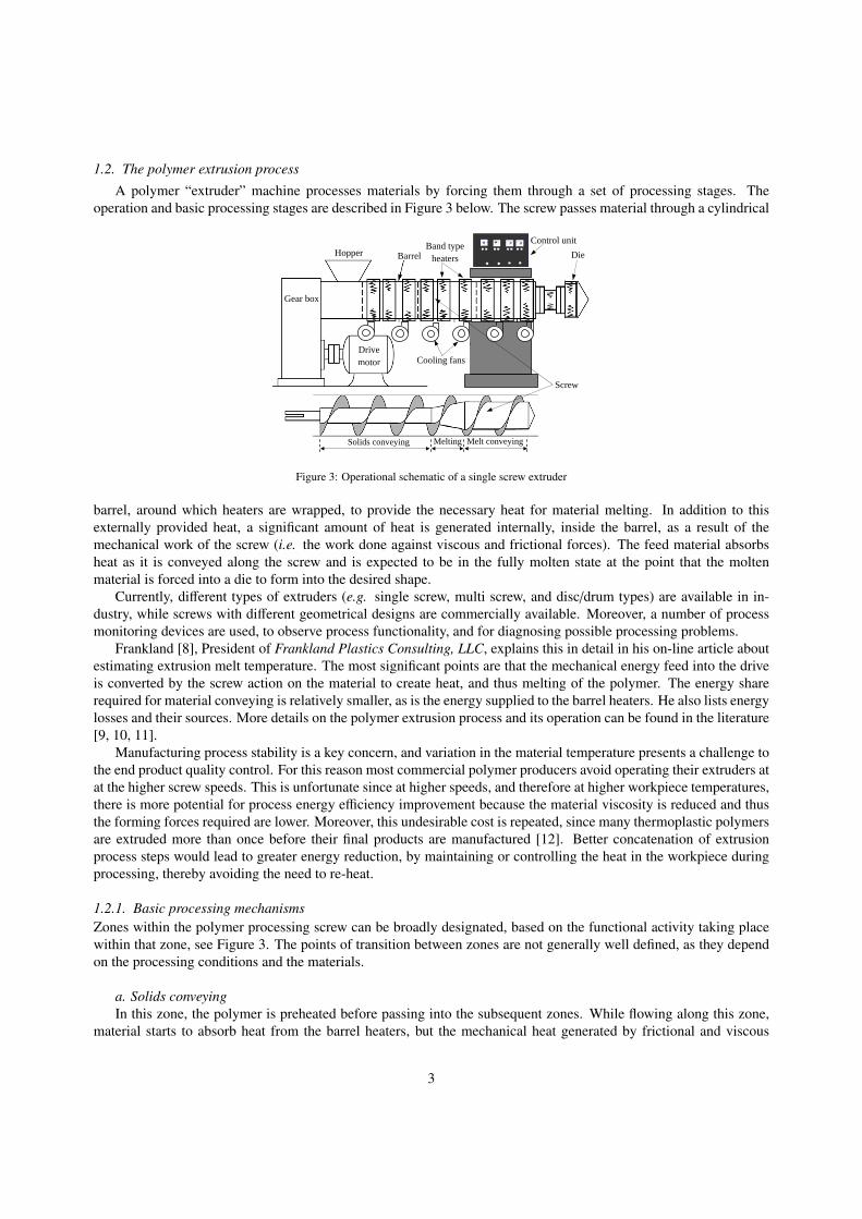
A polymer “extruder” machine processes materials by forcing them through a set of processing stages. Theoperation and basic processing stages are described in Figure 3 below. The screw passes material through a cylindrical
Clamp ring
Control unit
Barrel
Material
Breaker plate and screens
Screw cooling
Hopper
Gear box
Heaters
1 2 3
Solids conveying Melting Melt conveying
1 2 3
Drive motor Cooling fans
Band type heaters
Screw
Die
Figure 3: Operational schematic of a single screw extruder
barrel, around which heaters are wrapped, to provide the necessary heat for material melting. In addition to thisexternally provided heat, a significant amount of heat is generated internally, inside the barrel, as a result of themechanical work of the screw (i.e. the work done against viscous and frictional forces). The feed material absorbsheat as it is conveyed along the screw and is expected to be in the fully molten state at the point that the moltenmaterial is forced into a die to form into the desired shape.
Currently, different types of extruders (e.g. single screw, multi screw, and disc/drum types) are available in in-dustry, while screws with different geometrical designs are commercially available. Moreover, a number of processmonitoring devices are used, to observe process functionality, and for diagnosing possible processing problems.
Frankland [8], President of Frankland Plastics Consulting, LLC, explains this in detail in his on-line article aboutestimating extrusion melt temperature. The most significant points are that the mechanical energy feed into the driveis converted by the screw action on the material to create heat, and thus melting of the polymer. The energy sharerequired for material conveying is relatively smaller, as is the energy supplied to the barrel heaters. He also lists energylosses and their sources. More details on the polymer extrusion process and its operation can be found in the literature[9, 10, 11].
Manufacturing process stability is a key concern, and variation in the material temperature presents a challenge tothe end product quality control. For this reason most commercial polymer producers avoid operating their extruders atat the higher screw speeds. This is unfortunate since at higher speeds, and therefore at higher workpiece temperatures,there is more potential for process energy efficiency improvement because the material viscosity is reduced and thusthe forming forces required are lower. Moreover, this undesirable cost is repeated, since many thermoplastic polymersare extruded more than once before their final products are manufactured [12]. Better concatenation of extrusionprocess steps would lead to greater energy reduction, by maintaining or controlling the heat in the workpiece duringprocessing, thereby avoiding the need to re-heat.
1.2.1. Basic processing mechanismsZones within the polymer processing screw can be broadly designated, based on the functional activity taking placewithin that zone, see Figure 3. The points of transition between zones are not generally well defined, as they dependon the processing conditions and the materials.
a. Solids conveyingIn this zone, the polymer is preheated before passing into the subsequent zones. While flowing along this zone,
material starts to absorb heat from the barrel heaters, but the mechanical heat generated by frictional and viscous
3
mechanisms is dominant in this zone [13, 14, 10, 15]. Generally, the screw channel depth is maintained constant inorder to provide a constant material feed to the subsequent zones.
The first comprehensive theory for the action of solids conveying was developed by Darnell and Mol [16] in the1950s and this quantitative description still remains as the widely accepted model for solids conveying in extrusion.
b. Melting or PlasticationExperiments for studying the polymer extrusion melting mechanism were first carried out by Maddock and Street
in 1959 [17]. The melting mechanism proposed by Maddock for single screw extruders still remains as the mostwidely accepted melting mechanism in polymer extrusion. The Maddock melting mechanism is only a qualitativedescription of melting which occurs in single screw extruders. Maddock used a visual inspection method to investigatethe melting process by stopping the screw rotation suddenly during the process and ’freezing’ the polymer by coolingthe barrel and screw rapidly. Later, Tadmor also extended the understanding of melting mechanism of extrusionprocesses [18, 19, 20, 21].
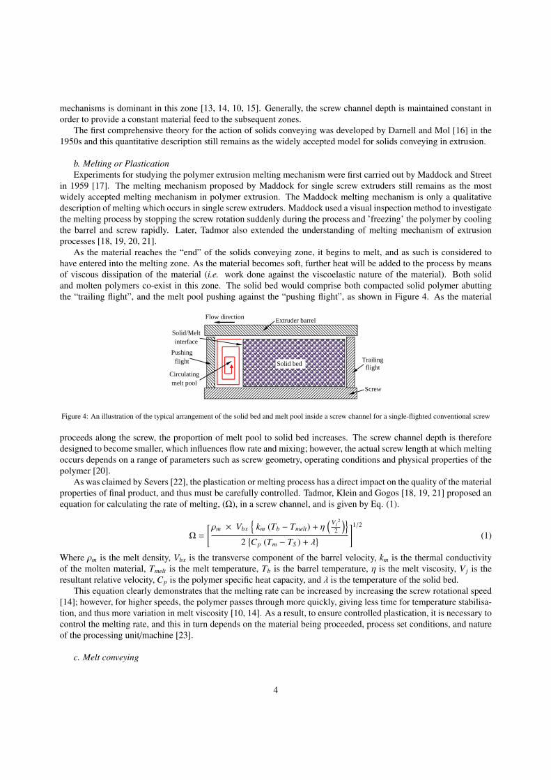
As the material reaches the “end” of the solids conveying zone, it begins to melt, and as such is considered tohave entered into the melting zone. As the material becomes soft, further heat will be added to the process by meansof viscous dissipation of the material (i.e. work done against the viscoelastic nature of the material). Both solidand molten polymers co-exist in this zone. The solid bed would comprise both compacted solid polymer abuttingthe “trailing flight”, and the melt pool pushing against the “pushing flight”, as shown in Figure 4. As the material
Trailing flight
Flow direction Extruder barrel
Solid/Melt interface
Circulating melt pool
Pushing flight
Screw
Solid bed
Figure 4: An illustration of the typical arrangement of the solid bed and melt pool inside a screw channel for a single-flighted conventional screw
proceeds along the screw, the proportion of melt pool to solid bed increases. The screw channel depth is thereforedesigned to become smaller, which influences flow rate and mixing; however, the actual screw length at which meltingoccurs depends on a range of parameters such as screw geometry, operating conditions and physical properties of thepolymer [20].
As was claimed by Severs [22], the plastication or melting process has a direct impact on the quality of the materialproperties of final product, and thus must be carefully controlled. Tadmor, Klein and Gogos [18, 19, 21] proposed anequation for calculating the rate of melting, (Ω), in a screw channel, and is given by Eq. (1).
Ω =
[ρm × Vbx
km (Tb − Tmelt) + η
(V j2
2
)2Cp (Tm − TS ) + λ
]1/2
(1)
Where ρm is the melt density, Vbx is the transverse component of the barrel velocity, km is the thermal conductivityof the molten material, Tmelt is the melt temperature, Tb is the barrel temperature, η is the melt viscosity, V j is theresultant relative velocity, Cp is the polymer specific heat capacity, and λ is the temperature of the solid bed.
This equation clearly demonstrates that the melting rate can be increased by increasing the screw rotational speed[14]; however, for higher speeds, the polymer passes through more quickly, giving less time for temperature stabilisa-tion, and thus more variation in melt viscosity [10, 14]. As a result, to ensure controlled plastication, it is necessary tocontrol the melting rate, and this in turn depends on the material being proceeded, process set conditions, and natureof the processing unit/machine [23].
c. Melt conveying
4

Melt conveying starts as complete melting is achieved. The screw channel depth is constant along the zone andis shallower than in the other two zones. During this stage further heating and mixing of the melt takes place as thepolymer is smeared by the tip of the screw flight against the barrel wall. Material has to be moved towards the diewith enough force to overcome the head pressure generated at the die – this is known as the “die head pressure”.
Melt output rate from this zone depends on a combination of two main factors: the rate of the rotation of the screwand the screw channel pressure gradient [24]. Proper mixing of material is another requirement for the flow throughthis zone. The melt conveying zone of some of the new screw designs is fitted with efficient mixer units to ensuregood mixing performance (e.g. the barrier flighted screw with a Maddock mixer).
Studies on melt conveying operation of extrusion were reported very much earlier than in the other two zones.One of the initial studies was carried out in 1920s [25, 26], which proposed the calculation of the melt conveying rateby considering the melt flow as a laminar fully developed flow. This is still a widely accepted model.
In addition to the above mentioned mechanism/theories, several other works have been reported later on improvingthe understanding of these three main mechanisms and more details can be found in the literature [14, 9, 10, 11, 27].
2. Energy required for materials processing
The assessment of energy requirements is not straight forward. The overall extrusion process can be broken downinto smaller activities, but even then, the power demands at each stage depend in a complex way on a large number ofprocessing parameters. A useful energy flow model was developed by Severs [22], as presented in Figure 5.
Figure 5: Typical energy flow diagram for an extrusion process
The energy, Eu, used by an extruder for useful work in material melting and forming, [28], is given by Eq. (2):
Eu = Ein − Elosses (2)
where Ein is the energy input to the extruder and Elosses is the energy expended that does not contribute to the extrusionprocess. Thus, the energy efficiency can be given by Eq. (3):
ηextruder =Ein − Elosses
Ein× 100% (3)
In these equations, the energy inputs (Ein) should be related to the energy consumed by the electrical componentssuch as drive motor, barrel/die heaters, barrel/motor cooling fans, water pump/s, instrumentation in the control unit,etc.. The energy losses are always associated with all the components and also occur due to forced cooling and vianatural convection and radiation, which can be accounted under Elosses. In general, the drive motor and the barrel anddie heaters are the source of the highest energy losses. In typical polymer extrusion processes, recovery of such lostenergy is impractical, as this is largely released as heat energy to water or air. More details concerning the energyrequired for polymer processing and the thermodynamic efficiency of an extruder have been discussed by the authorspreviously [28].
3. Prior art in extruder energy evaluation, monitoring and modelling
3.1. Energy Consumption studiesIn considering the energy consumption in any industrial process, the first step is to review the process capabilityof the existing or available plant machinery, and the power consumption. On that basis, potential modifications or
5

enhancements to machinery could be identified, where an economic case could be made on the basis of energy costsaving. Some examples are given below.
In the late 1970s, Chung et al. [12] found that for a 63.5 mm diameter extruder mechanical energy efficiency of62% was typical, and for larger extruders the energy efficiency was lower. In 1981, Kruder and Nunn [29] claimedthat energy efficiency of extruders can range from 45%-75%. It was noted that the energy efficiency depended on thetransmission mechanism, screw design, product geometry, nature of polymer feedstock and the production rate, whilethe major energy losses of an extruder occur as a result of the forced cooling process step, and the losses associatedwith the drive and transmission unit. At low screw speeds, barrel heaters consume a considerably higher portion ofenergy than at higher speeds, and significant energy savings could be made by running the processes at the highestpossible power factor. Additionally, this work presented information on energy demand and losses of each individualcomponent of an extruder.
Subsequently through the 1980s, most research into energy efficiency was focussed on the screw efficiency andmass flow rate. A reduction in the overall power requirement for an extruder can be achieved through the use of ageared pump at the end of the extruder to increase the mass flow rate (McKelvey [30]). In 1985, Strauch et al. [31]carried out an energy consumption study on a 63.5 mm diameter single screw extruder, and observed that most of theenergy was consumed by the mechanical parts, with less significant levels of consumption in process heating. Theenergy conversion was then assessed and it was found that heating the water in the cooling system accounted for morethan half of the energy supplied.
During the late 1980s and 1990s, the manufacturing sector was making many changes, with a view to improvingproductivity and quality. Driven by the advances made in Japanese manufacturing, the main focus during that timewas on management methods, such as Total Quality Management, LEAN, and Six Sigma. These efforts initiallyaddressed cost and time issues, where the biggest economic benefits were to be found. Latterly, interest in energyefficiency began to be seen as not only cost reduction opportunity but also as an environmental imperative.
In the context of power consumption in the extruder, in 1997 Anderson et al. [32] recognised that for the processingof most plastics, from room temperature, the specific energy consumption (SEC) of the extruder motor should be inthe range of 0.0822 to 0.1644 kW.hr/kg.
At around the same time, a study by Falkner in 1997 [33] showed that motor operations accounted for over 65%of the 1994 UK industrial electricity usage. Asserting that more than 10% of this energy could be attributed toinefficiency, Falkner argued that this represented a loss of about £0.5 billion to the annual UK economy. These valuesaccounted for motor energy utilisation across multiple industrial sectors, but it should be recognised that the electricmotors in plastics industry processing machines are a major power consumers.
A more detailed study by Rosato et al. in 2001 [34] observed that energy losses of between 3 and 20% can arise inthe transmissions and control systems. Despite this, a conclusion was made that because plastics have lower specificenergy requirements compared with most conventional raw materials, they are still highly competitive.
Five years later, Womer et al. [35] considered the energy efficiency of extruder cooling. The results demonstratedthat water cooling systems consume more energy compared with air cooling, irrespective of the particular plastic beingprocessed. As a result, a recommendation was made to use air only cooling unless extensive cooling was expresslyrequired.
In 2010 [36], the plastics industry was recognised to be one of the major UK industries with a similar trendapplying globally. On that basis any improvement in process energy efficiency would lead to a considerable reductionin global energy requirement. Also in 2010, Cantor [37] presented measurements of SEC, where the impact of themotor and of each individual heater zone, with respect to the overall specific energy consumption, was separatelyrecorded. It was observed that the heaters account for over 95% of the supplied energy. In a slightly later studyby Heur and Verheijen [38], the authors studied differences from one plant to another, and recommended the use offrequency controllers to enable more precise process control.
The earliest mention of an Industry 4.0 implementation to energy efficiency control was by Jing et al. (2014) [39]which proposed the use of real-time monitoring. The rationale was to render unnecessary the installation of powermeters or the development of data-driven models. A fuzzy logic controller controlled the high melt quality in a singlescrew extruder, and was shown to be a cheaper alternative to using a gear pump. This also paved the way for achievinggreater extruder energy efficiency by optimising the temperature settings.
A number of other works [35, 40, 41, 42, 43, 44, 45] consider the drive motor efficiency compared with otherdevices. The conclusion to be drawn is that the drive motor should be the primary design consideration for process
6

engineering the energy efficiency of the whole extrusion plant.
3.2. Influence of process set parameters
In 2001, Rauwendaal [10] recognised the significance of process settings, and presented an account of a procedureto minimise power consumption. A little later, in 2003, Rasid and Wood [46] investigated the influence of individualbarrel zone temperatures and found that the solids conveying zone temperature had the greatest influence on overallpower consumption.
Studies carried out between 2004 and 2012, [47, 48, 49, 50], examined various process parameters and theirinfluence on SEC. In addition to noting the effect of material viscosity, variation in energy consumption was also seenfor different designs of screw, and there were greater melt temperature fluctuations at higher screw speeds: anotherexample of the ever-present tension between cost and quality. The simultaneous need to achieve both energy efficientoperation and finished part quality remains a challenge.
Studies carried out by Abeykoon et al.[51, 28, 52, 53] between 2009 and 2016, focussed on the relationshipbetween the process energy demands of the motor and barrel heating and melt thermal stability. The effects of thesettings for these processes, the screw geometry and choice of material were explored.
3.3. Modelling
Following a thorough trawl of the published scientific literature, it has become clear that relatively little work has beenundertaken to model extruder energy consumption.
The earliest work in this area was by Mallouk and Mckelvey [54] in 1953, where a mathematical equation wasdeveloped, based on assumptions of isothermal, Newtonian flow, in a screw channel with constant section. In 1996,Wilczynski [55] developed a computer model where the five zones of the extruder plus the die were consideredseparately. Subsequently, in 2000, Lai and Yu [56] also proposed a mathematical model for the calculation of energyconsumption based on screw speed, and including viscosity. In Abyekoon et al.’s [57, 52] studies of a single screwextruder, the data collected was analysed using static nonlinear polynomial models. The conclusion of the analysiswas that choosing energy efficient process settings would also lead to thermal stability.
Obviously, the availability of advanced modelling methods for predicting energy consumption, based on processparameters, would enable process operators to select optimum operating conditions. In particular, models whichincorporate both energy consumption and melt thermal quality would be preferred but the development of such modelsis quite challenging. Melt thermal quality and energy efficiency present opposite behaviours with respect to theprocessing speed: the thermal quality deteriorates while the energy efficiency improves. Since the industrial sectorhas to meet strict environmental regulations to minimize the carbon footprint, any reduction in the energy demandsfor polymer processing would support future sustainability.
3.4. General considerations in energy usage
According to basic electricity principles, the typical power consumption of a DC and an AC device (PDC and PAC) isgiven by equations (4) and (5), respectively [58, 59],
PDC = V × I (4)
PAC = V × I × cos φ (5)
with I being the supply current, V voltage, and cos φ the “displacement power factor”. From these, the power demandof any device in an extrusion plant can be evaluated; however, the energy losses related to each device might varyfrom component to component.
The power factor is an important consideration in the assessment of the energy usage of an electrical machine orprocess, and is defined as either the “displacement power factor” which is the cos φ in Eq. (5) or the “true powerfactor” which is given by Eq. (6).
True power factor =True (or active) power
Apparent power(6)
7
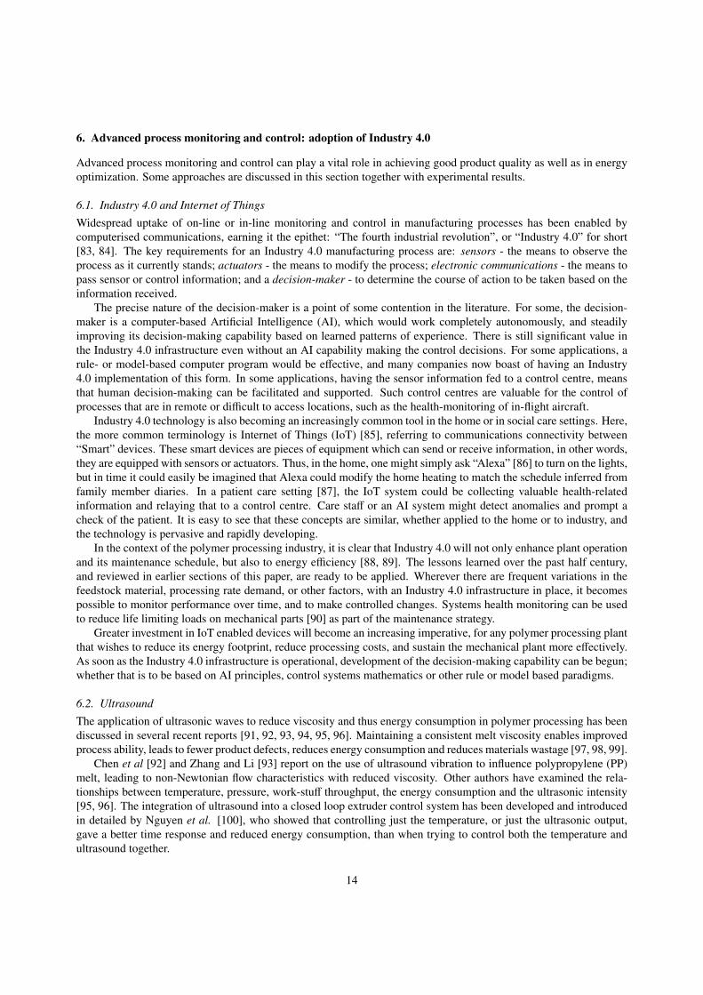
Usually, an AC power flow has three components known as real power (also known as active power) (P), measured in watts (W); apparent power (S), measured in volt-amperes (VA); and reactive power (Q), measured in reactive volt-amperes (VAR) as shown in Fig. 1. The power factor is defined as the ratio of the real power flowing to the load, to the apparent power in the circuit and it ranges from 0 to 1. In other words, if / is the phase angle between the current and voltage, then the power factor is equal to the cosine of the angle, cos /
Apparent power (S) (units: VA)
Reactive pow
er (Q)
(units: VA
R)
Active power (P) (units: W)
Impedance phase angle
Figure 6: Power triangle showing the relationship between active, apparent and reactive powers
The true power factor lies in the range 0 – 1, for which the running of the machine or process with true power factorequal to one would be the best possible energy efficient operating condition (when the impedance phase angle shown inFigure 6 is equal to zero). For a true power factor of less than one, the energy supplied to the load is not used optimally.In such a case, a higher current must be drawn to compensate for the phase shift, φ. Where industrial customers operatewith power factors below around 0.95, [60], this represents unbalanced additional power demands from the powersupplier, and hence additional infrastructure demand leading to additional costs. Furthermore, electrical devices areattributed with a I2×R heat loss (R is the electrical resistance) , so that increasing the required current while reducingthe power factor results in an increase of power loss as heat.
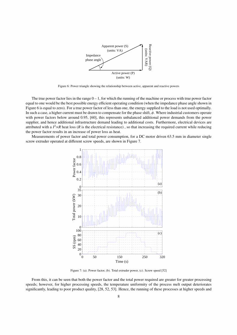
Measurements of power factor and total power consumption, for a DC motor driven 63.5 mm in diameter singlescrew extruder operated at different screw speeds, are shown in Figure 7.
0
0.2
0.4
0.6
0.8
1
0
10
20
30
35
0 50 150 250 3200
20406080
100
Pow
er f
acto
r T
otal
pow
er (
kW)
SS
(rp
m)
Time (s)
(a)
(b)
(c)
Figure 7: (a). Power factor, (b). Total extruder power, (c). Screw speed [52]
From this, it can be seen that both the power factor and the total power required are greater for greater processingspeeds; however, for higher processing speeds, the temperature uniformity of the process melt output deterioratessignificantly, leading to poor product quality, [28, 52, 53]. Hence, the running of these processes at higher speeds and
8

with the highest possible power factor is problematic, despite being desirable for energy efficiency.
4. Potential for energy efficiency improvements
Energy demands and losses are illustrated in the form of an energy flow diagram, Figure 8. This diagram may be
Figure 1: A typical energy flow diagram for an extruder
Energy content in the feed material
Drive motor
External heating/cooling
Drive motor losses
Forced cooling losses
Natural cooling losses
Other losses
Transmission losses (gear
box)
Energy used for material melting and
forming
Energy for other auxiliary
devices
Figure 8: A typical energy flow diagram for an extruder [52]
extended for any auxiliary devices connected with the plant.
4.1. Drive motor and gear box
The key component of any extrusion machine is the screw, which can be driven by a controllable direct current(DC) or an alternating current (AC) motor, or indeed by a hydraulic drive [10, 61]. The screw and the motor areconnected through a gear box with fixed or adjustable transmission ratio, as shown in Figure 3. For the case ofan extruder with a DC motor drive, see the schematic, presented in Figure 9. Additionally, the machine can havesensing and control devices related to its operation, for example, PID temperature controllers to control set barrel/dietemperatures. Extruders with AC motor drives are essentially similar (with no rectifier), and may have additionalcomponents depending on the type of the motor.
(ωset ωactual) Actual screw speed (ωactual)
DC motor
Tachometer generator
PID Motor speed controller
Gear box
Armature voltage (Va) changes to adjust the
motor speed
Set screw speed (ωset)
Screw +
ωactual
Figure 9: A schematic of an extruder drive mechanism
Figure 10 shows measured motor power and total power consumptions, for the case of a 63.5 mm diameter singlescrew extruder with a DC motor, driven at different screw speeds. The contribution of heaters to the total powerdemand is also indicated. As marked on Figure 10, all the heaters were turned off at around 330 s and this has led tosmooth out the total power signal which were fluctuating due to the on-off action of the barrel/die heaters.
The drive motor is one of the major energy consuming components of an extruder [31, 34, 40], and, along with thegear box, is also responsible for significant energy losses, typically accounting for around 20% of the power suppliedto an extruder [29]. In particular, DC motors are inefficient when operated at below the rated speed. Commerciallyavailable DC motors fall into three main categories: “permanent magnet”, “separately excited” and “self-excited” .The first two are more commonly used. A block diagram for a polymer processing extruder with a “separately exciteddirect current” (SEDC) motor is shown in Figure 11.
9

0 100 200 300 400 500 6000
20
40
60
80
100
0 100 200 300 400 500 600-10
0
10
20
300 100 200 300 400 500 600
0
60
100
Time (S)
Pow
er (
kW)
SS
(rp
m)
Total power
All the heaters turned-off Motor power
(a)
(b)
Figure 10: (a). Screw speed (SS), (b). Motor power and total power signals over the time [52]
Ia Tm ωm
TL
ωsc Gear Box
+ mm RSL +
1
mm BSJ +1
N1
Km
+ -
Scr
ew
Kf Vf
Va + -
Electrical dynamics
Mechanical dynamics Eb
-Kt
Speed controller
Figure 11: Block diagram of an extruder with a variable field DC motor [62]
10

In this figure, Tm is the motor torque, TL is the load torque on the screw, Ra and La are the armature resistance andarmature inductance respectively, K f and Kt are the torque constants related to the field and motor, respectively, Ia isthe armature current, V f is the field voltage and Bm and Jm are the damping constant and the steady-state inertia of theloaded screw, respectively. For extruders with a permanent magnet motor, the same block diagram is valid withoutthe branch related to the separately excited field (with V f and K f block).
Reasons for the popularity of DC motor drives in the polymer processing industry [63, 64, 52] include:• Smooth operation over a wide speed range,• Simplicity in speed control,• Production of a constant/consistent torque from zero to base speed ,• Relatively low power/energy consumption,• Relatively smaller size compared to other drive types with the same capacity,• Compact and simple power circuit, engaged with Silicon-controlled rectifiers,• Easy installation,• High reliability,• Low intial capital cost, and• Less noisy than AC motors.
Drawbacks of DC motor drives include the need for maintenance of brushes and commutator as well as the energyloss known as “brush loss” [59]. Green [63] observed that the best power factor that can be achieved by a DC motoroperated at its top speed is of approximately 0.87, whereas for the best possible efficiency the power factor should beclose to 1.
Currently, AC motor drives are increasing in popularity since the power factor can be maintained constant acrossthe entire speed range. As a result, companies can avoid paying penalty charges for lagging power factor conditions.The most significant drawback of AC motors is that they require a constant current to produce a constant torque, hencedemanding constant cooling regardless of the motor speed [63], and this results in an additional energy cost. Otherissues include the fact that AC motors are generally larger, by a factor of 1.5-2.1, in volume, as well as being morecomplex than DC motors. These issues are becoming less critical nowadays, thanks to advances in electronics suchas large scale chips and micro-processors. For both types of motors, while under operation at the rated speed, themaximum energy efficiency can be achieved, industrial extruders are typically operated at lower speeds in order toavoid undesirable fluctuations, particularly of the melt thermal quality.
Barlow [40] argues that because the displacement power factor of a DC motor drive is proportional to the speed,the power factor reduces as the motor slows down (see Figure 7). Further, it is pointed out that because the diodebridge of the input section of a pulse-width-modulated AC vector control drive rectifies the AC into DC, and that theenergy is stored in capacitors, the current and voltage waveforms are mutually in phase, and hence the motor operatesat a power factor, in the range of 0.90 to 0.98. More information on these motor drives can be found in the literature[65].
It seems that a significant amount of electrical energy may be lost simply as a result of the low power factoroperation of motor drives [44]. Here, Eickelberg [66] suggests that use of capacitors may be one of the solutions tothis problem, to smoothen the power supply. Several examples of the use of capacitors by commercial processes areprovided, but it is stated that this is unlikely to be a practical solution for polymer extrusion processes because ofthe variability that occurs in the load. The installation of a more appropriate form of power factor correction wouldrequire investigation of the relevant issues [67].
Kent [41] observes that in extrusion plant energy usage assessments the energy requirements of motors in equip-ment such as extruders and injection moulding machines is often over-looked. Other authors [68, 69] report thatconsiderable energy savings can be achieved by replacing DC motors with AC motors. Lounsbury and Karafilidis[70] present factors to be considered in the selection of a drive motor.
4.2. Barrel and die heaters
Normally, three different types of heating method can be identified in extrusion. These are known as “resistanceheating”, “induction heating” and “fluid heating” [61].
11

Resistance heating: This is also called electrical heating, and is the type most frequently used in extruders.Usually, electric heaters offer several advantages over fluid and steam heating, such as the possibility of coveringa broader temperature range, cleanliness, easy maintenance, low cost, and better efficiency. As a result of theseadvantages, fluid and steam heaters have been replaced by electric heaters in modern applications. Currently extruderstypically have between two and ten heating zones depending on the size of the extruder.
In the most common conventional resistance heaters, the heat from the resistance wire is transferred to ceramicsegments that surround the outer surface of the barrel. This heats the barrel up until its inner surface is hot: the heatis then transferred to the plastic in the machine so it can be processed. With this heating method, much of the heatgenerated is wasted.
Induction heating: In this case, an AC current is passed through the primary coil surrounding the extruder barrel.This gives rise to an eddy current. Where the material being processed has significant relative permeability, heat mayalso be generated by magnetic hysteresis. A high energy density can be achieved quickly with induction heating. Thefrequency of the AC is selected depending on the size and material type and the heat penetration depth.
With the advantage of rapid heating and energy efficiency, induction heating has been used in many industrialapplications [71]. The key advantage of induction heating over resistance heating is that the extruder barrel itselfbecomes the heating element. This eliminates the conduction problem that exists with conventional heaters. As thereare no ceramic layers, clamping bands, or water jackets to heat up, the heat is direct and instantaneous. Furthermore,the induction heating generates a very even and precise heat profile, ensuring consistent heating of the polymer meltand leading to improved product quality. The application of induction heating to polymer processing has been devel-oped by the Nordson Xaloy Company, which claims a reduction in heating related energy consumption of up to 50%compared with typical band electric heaters [72, 73].
Fluid heating: Fluid heating uses hot liquid or steam passing through pipes/tubes. This can ensure even temper-ature distribution but has significant disadvantages, such as demanding high levels of maintenance, the possibility ofleaking or corrosion, and system complexity.
An alternative all three heating methods, is to supply the energy to the material being processed as drive powerrather than as heater power [44, 74]. In this way shearing of the material leads to both heating and mixing. Ofcourse, direct heating and cooling can be essential, to maintain the process thermal stability, but as guiding principlesit would be preferable to minimize the direct heating and to avoid exceeding the melt temperature, in order to avoidunnecessary energy costs.
4.3. Control electronics and monitoring devices
A number of control and monitoring devices are used in extrusion lines, such as speed and temperature controllers andindicators; pressure indicators and gauges; dimension scanners; feed monitoring devices; current indicators; relays;switches; alarms; etc.. All of these use some power for their operation; however, this is insignificant compared to thetotal energy demand. This is evident from the experimental data presented in Figure 10-(b), the amount consumed bycontrol electronics and monitoring devices are shown by the difference between blue and red lines (i.e., the differencebetween to total and motor powers) after turning off all the heaters, or by the blue line roughly between 540-570 safter turning off all heaters and the motor.
4.4. Auxiliary equipment
Auxiliary equipment, such as pelletizers, gear pumps and screen changes, might also consume enough power to beconsidered in energy evaluations. Rice [75] suggests that improved energy efficiency for the entire operation of theplant can be achieved by combining processes.
4.5. Process cooling
Process cooling is required where there is a need to remove excess heat in order to maintain the process thermalstability. This can be achieved by fan coolers attached along the barrel, or by cooling the screw core or the barrel wallinternally, using a cooling fluid such as water or oil. Air cooling provides slower changes in temperature comparedwith liquid cooling.
12

Although cooling helps to ensure stable process operation, improper cooling, particularly cooling of the screw,can lead to the generation of undesirable process fluctuations. Strauch [31] argues that excessive screw core coolingcan lead to a reduction in throughput rates, while at the same time affecting the melt temperature. This also impactson the pumping stability as a direct consequence of altering the viscosity of melt. Periodic or random temperaturevariations of the extruder metal surfaces can arise as a result of cooling problems with the screw or barrel, and thesemay lead to melt flow problems such as melt viscosity fluctuations [76].
The research of Womer et al. [35] into the effects of cooling indicated that, where water cooling is used ratherthan air cooling, the extruder consumes more energy, irrespective of the material being processed. In consequence,it is recommended to use air cooling only, in conjunction with a properly designed screw, unless extensive cooling isrequired.
5. Trends in polymer processing energy efficiency improvements
5.1. Machine development and operational modifications
Among the current research and development “hot topics” for process energy efficiency, the three most likely to deliversignificant benefits [63] are: (i) the design of direct drive extruders, (ii) improvements in heater and barrel design toreduce heat losses, and (iii) thedevelopment of “advanced vector control alternating current (AC) drives”. In additionto these, there are reports which claim that direct drive machines offer further advantages including energy efficientoperation, narrow footprint, quiet operation, and low maintenance requirements. The use of insulation blankets hasalso becoming popular in energy saving of machines.
“Load management” offers the possibility to save power in the near term. The idea is to achieve the required energycost reduction by maintaining the load factor, rather than focusing on power consumption per se. Since commercialelectrical energy supply rates usually depend on the peak demand made by the customer, this can reduce the cost of theelectricity used over the duration of the charging period. To operate an effective load management plan, it is necessaryto have a plant monitoring system to study the real-time plant power usage. In Kent’s [41] discussion of energy savingin polymer processes, it is pointed out that the purchase of energy efficient capital equipment is profitable in long-rundespite initial capital costs.
5.2. Waste heat energy recovery
Although a significant amount of process heat is removed purposely to maintain the thermal stability in polymerextrusion, there has been insufficient attention on the recovery of waste heat for useful work.
The challenge [42, 77] is to find a means of re-use for that energy. Future research is required to explore suchopportunities. For example, the recovered heat might be used for pre-heating the material prior to feeding into thehopper, or it could simply be used for space heating.
For some materials, resins need to be pre-heated prior to processing to remove moisture. In this case, part of thesupplied energy is lost through the evaporation of the moisture as water vapour, part is lost to heating of the surround-ings, and the rest contributes to heating the resin. If the drying operation takes place remotely from the processingmachine, then the heat absorbed by resin will be lost during transit to the processing machine. Therefore, the re-designof the drying system, as an in-line step of the processing machine, should help to reduce overall processing energycosts.
5.3. Material choice, material recycling and disposal
It is usually the case that the manufacture and fabrication of plastic products makes lower energy demands thanequivalent traditional metallic or glassware products. The development of new resins that can be processed at lowertemperatures, and hence for reduced energy, is part of the growing tide of interest to cut process energy expenseseven further [78, 79, 80, 81]. On the other hand, polymeric materials based waste management has become a globalconcern. A wide range of recycling techniques are available depending on the types of polymers and the manufacturingtechniques used [82]. In regard to process energy costs, the energy consumption for plastics is lower than for materialssuch as paper, glass, tin, and aluminium. What is more, Rosato et al. [34], the incineration of plastics as part ofmunicipal waste yields much more energy than other material waste, such as food waste, paper and rubber, and wastevolume can be reduced by 90-98%.
13
6. Advanced process monitoring and control: adoption of Industry 4.0
Advanced process monitoring and control can play a vital role in achieving good product quality as well as in energyoptimization. Some approaches are discussed in this section together with experimental results.
6.1. Industry 4.0 and Internet of Things
Widespread uptake of on-line or in-line monitoring and control in manufacturing processes has been enabled bycomputerised communications, earning it the epithet: “The fourth industrial revolution”, or “Industry 4.0” for short[83, 84]. The key requirements for an Industry 4.0 manufacturing process are: sensors - the means to observe theprocess as it currently stands; actuators - the means to modify the process; electronic communications - the means topass sensor or control information; and a decision-maker - to determine the course of action to be taken based on theinformation received.
The precise nature of the decision-maker is a point of some contention in the literature. For some, the decision-maker is a computer-based Artificial Intelligence (AI), which would work completely autonomously, and steadilyimproving its decision-making capability based on learned patterns of experience. There is still significant value inthe Industry 4.0 infrastructure even without an AI capability making the control decisions. For some applications, arule- or model-based computer program would be effective, and many companies now boast of having an Industry4.0 implementation of this form. In some applications, having the sensor information fed to a control centre, meansthat human decision-making can be facilitated and supported. Such control centres are valuable for the control ofprocesses that are in remote or difficult to access locations, such as the health-monitoring of in-flight aircraft.
Industry 4.0 technology is also becoming an increasingly common tool in the home or in social care settings. Here,the more common terminology is Internet of Things (IoT) [85], referring to communications connectivity between“Smart” devices. These smart devices are pieces of equipment which can send or receive information, in other words,they are equipped with sensors or actuators. Thus, in the home, one might simply ask “Alexa” [86] to turn on the lights,but in time it could easily be imagined that Alexa could modify the home heating to match the schedule inferred fromfamily member diaries. In a patient care setting [87], the IoT system could be collecting valuable health-relatedinformation and relaying that to a control centre. Care staff or an AI system might detect anomalies and prompt acheck of the patient. It is easy to see that these concepts are similar, whether applied to the home or to industry, andthe technology is pervasive and rapidly developing.
In the context of the polymer processing industry, it is clear that Industry 4.0 will not only enhance plant operationand its maintenance schedule, but also to energy efficiency [88, 89]. The lessons learned over the past half century,and reviewed in earlier sections of this paper, are ready to be applied. Wherever there are frequent variations in thefeedstock material, processing rate demand, or other factors, with an Industry 4.0 infrastructure in place, it becomespossible to monitor performance over time, and to make controlled changes. Systems health monitoring can be usedto reduce life limiting loads on mechanical parts [90] as part of the maintenance strategy.
Greater investment in IoT enabled devices will become an increasing imperative, for any polymer processing plantthat wishes to reduce its energy footprint, reduce processing costs, and sustain the mechanical plant more effectively.As soon as the Industry 4.0 infrastructure is operational, development of the decision-making capability can be begun;whether that is to be based on AI principles, control systems mathematics or other rule or model based paradigms.
6.2. Ultrasound
The application of ultrasonic waves to reduce viscosity and thus energy consumption in polymer processing has beendiscussed in several recent reports [91, 92, 93, 94, 95, 96]. Maintaining a consistent melt viscosity enables improvedprocess ability, leads to fewer product defects, reduces energy consumption and reduces materials wastage [97, 98, 99].
Chen et al [92] and Zhang and Li [93] report on the use of ultrasound vibration to influence polypropylene (PP)melt, leading to non-Newtonian flow characteristics with reduced viscosity. Other authors have examined the rela-tionships between temperature, pressure, work-stuff throughput, the energy consumption and the ultrasonic intensity[95, 96]. The integration of ultrasound into a closed loop extruder control system has been developed and introducedin detailed by Nguyen et al. [100], who showed that controlling just the temperature, or just the ultrasonic output,gave a better time response and reduced energy consumption, than when trying to control both the temperature andultrasound together.
14
6.3. Closed loop melt temperature control
Melt temperature can serve as a proxy parameter for melt viscosity and can thus be used to determine the melt quality.Recent works by Abeykoon et al [101, 102, 103] incorporate a fuzzy logic approach for the real-time closed loopcontrol of melt temperature, and demonstrated excellent performance in achieving desired set temperatures.
At present, in the majority of polymer processes, melt pressure and melt temperature are taken as the key param-eters for process functionally and control. Screw speed, and barrel and die set temperatures are taken as the mainprocess control parameters, but there is no actual feedback taken from the process melt for making process controldecisions, so no corrective actions can be taken to avoid product defects. Furthermore, this affects the production rateleading to wasted energy, labour and raw materials. Hence, combined process monitoring and control approaches,which can observe the melt quality and take control actions would represent a major development of polymer pro-cesses.
7. Applying computational process simulation and dynamical systems to Control
Developments in computational process simulation methods has the potential to revolutionise the design of manu-facturing tooling and processes. Capabilities such as finite element method and computational fluid dynamics havedeveloped very significantly, with most commercial packages (e.g. [104, 105, 106, 107, 108, 109]) now offeringmulti–physics simulation: simulation of static and transient solid mechanics, fluid dynamics, thermodynamics, elec-tricomagnetism, and in many cases, much more. Given the improvements in computer hardware, storage capacityand the development of parallel processing architecutures, computational analyses with high levels of geometric ormaterial modelling complexity can now be readily envisaged. This is a huge opportunity to grasp, and one for whichmost industrial plants are not fully prepared.
7.1. Computational mechanics methods
The key computational capabilities pertinent to polymer processing include a variety of modelling techniques for vis-coelastic materials irrespectively of whether they should be treated as solids or liquids. Where previously, modellingbased on a Lagrangian Finite Element formulation, [110], would have been unable to capture the necessary defor-mation, Eulerian formulations, [111], and Smooth Particle Hydrodynamics (SPH), [112] and [113], now have thatpotential. Perhaps it is not enough to model using just one technique or another, but to capture one pertinent aspectof the physics in one region of the process, and another aspect in another region using such modelling techniques asco-simulation and subdomain modelling.
Not only it is the type of analysis that is of importance to capture the process simulation requirement, but also theway in which the material properties are represented. The distinction between solid and liquid is no longer so clear-cut. There are very many material models, developed and applicable to different analysis types, that will capture theessential material property physics of any realizable material. Polymers offer particular challenges, but characteristicssuch as static stress–strain, strain rate dependence, creep, and temperature dependence are readily modelled. Chemicalchanges, including exo– or endothermic reactions, and cure shrinkage still present a particular challenge to thermosetpolymers, but for thermoplastic processing the challenge of representing materials properties at glass transition, andextent of crystallization, are, if not straight forward, at least more tractable [114, 115, 116]. For the characterisationof polymers undergoing extrusion processing Abeykoon et al, [117], have made significant investigations.
With the increase of computing power and the capability for higher model complexity there has been increasedinterest in the application of computational mechanics methods using sophisticate material models to the simulationof the extrusion process. In the past decade authors such as Zairi et al, [118], have been able to model plastic flow,taking account of viscoelastic properties, within a die of finite constrained section, and have been able to make someprediction of the microstructure of the end product. While the main focus has been of the effect of the die geometryon the extruded product, another important consideration is the design of the die tooling, and the loads that mustwithstand during processing [119].
15

7.2. Statistical process control
The biggest challenge for the modelling of the polymer extrusion process is to understand the conditions that give riseto large variations in product output quality. Where small changes in the processing parameters lead to only smallchanges in output, even where the change is clearly non-linear, one might take a step-wise approach to linearize theparameters and have a measurable and definable set of limits for process control. This is the ideal, textbook, approachto manufacturing process excellence, LEAN manufacturing or Six Sigma, [120], [121]. In constrast, where smallchanges in processing input lead to significant changes in the output quality, a manufacturing engineer would say thatthe process is not in statistical control. The usual manufacturing engineer’s approach for regaining statistical controlis to monitor parameters to within ever tighter bounds. Clearly this would lead to increased manufacturing costs, andcould make the process financially unviable. The approach may ultimately even be completely unsuccessful.
The factors that would generally be considered for statistical process control would include the initial conditions:how the process is started up, and the material condition on start-up, factors directly related to the geometry of theextruder and the die, environmental conditions and changes, and changes in the raw material batch.
In order to control the process, certain actions might be taken. The applied drive torque, a function of the powersupplied to the extruder, could be controlled in direct response to measurements relating to the process quality. In-evitably there is a delay between making the measurement, and making a change, primarily because the measurementis taken at some point down-stream in the process. There is a considerable level of research activity in this area, withvarious computational schemes for assessing these measurements and informing the choice of control action to betaken. Clearly this data processing time must be minimised to minimise the feedback delay. Wagner et al, [122], andMcKay et al, [123], recognised that the fundamental requirement was to use the measurements to infer the local mate-rial viscosity within the process, using artificial intelligence methods such as neural nets. Chen et al, [124], employeda power law model. Methods based on fuzzy logic were developed by McAfee, [125], McAfee and Thompson, [126],and later by Liu et al, [127] and Abeykoon [103]. More recent work includes the soft sensor technique of Deng et al,[128] and Abeykoon [102], and the multi-objective optimisation approaches presented by Carrano et al, [129].
7.3. Non-linear system dynamics
Where the dynamics of the manufacturing process make statistical process control challenging, a radically differentapproach is needed. Non-linear systems dynamics [130] has been a topic of considerable research and development,mainly by researchers with a strong background in applied mathematics, and with applications including but by nomeans limited to manufacturing engineering applications. By developing a non-linear system dynamics representationof a manufacturing process, it is possible to explore how process parameters could influence the process dynamics,and from this pin-point the controling factors or initial conditions.
In the field of polymer extrusion modelling, McKinley, et al, [131], used laser doppler velociometry to visualisethe flow towards an abrupt contraction, and found that the flow near the tip of the contraction could show time periodicand aperiodic behaviour. Graham [132] modelled the fluid behavious regarding wall slip and was able to replicate thelarge amplitude periodic and aperiodic oscillations observed experiementally. Smith et al, [133, 134] demonstrate asteady-state solution through modelling the polymer as a purely viscous non-Newtonian material, and optimising diegeometry.
The critial feature in the extrusion process is the variation in the material property of the polymer as it passesthrough the process. As the material is being worked mechanically, it becomes heated. As it gets hotter, the elasticstiffness and viscosity are reduced. The resulting thermal expansion gives rise to a localised increase of pressure.As a result of both the reduced viscosity and increased pressure, the polymer would pass more readily through theprocess: and would require less working. Reduced working would result in reduced heating, with the result of inceasedstiffness, increased viscosity and reduced pressure. It is clear that a cyclic response can be expected. Now considerhow the viscosity of the polymer changes with strain rate and the difference of time dependency in glass transition andcrystallization, it bceomes clear that there is a level of complexity between production rate, localized temperature andviscous response of the material: in the simplistic mass, spring and damper system it is the variability of the damperas well as the forcing that is key to understanding the dynamical system.
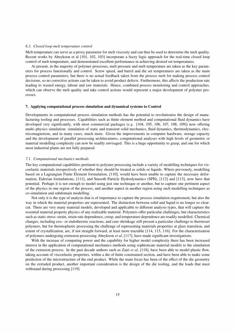
A non-linear dynamical systems model of the polymer extrusion process might be modelled as follows. First,the polymer has the properties of both an elastic solid, and a viscous fluid: it can be idealized as a mass, springand damper system, as shown in Figure 12. The non-linear dynamics of such systems have been studied for many
16
idealized situations of varying applied force, F(t), and their modelling involves the selection of initial conditions, andthen computing the transient behaviour until a long term behaviour becomes apparent.
Figure 12: Idealised mass, spring and damper system
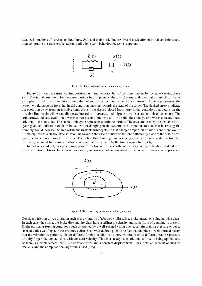
Figure 13 shows the time varying position, x(t) and velocity x(t) of the mass, driven by the time varying forceF(t). The initial conditions for the system might be any point on the x — x plane, and one might think of particularexamples of such initial conditions being the tail end of the solid or dashed curved arrows. As time progresses, thesystem would move on from that initial condition, moving towards the head of the arrow. The dashed arrows indicatethe evolution away from an unstable limit cycle – the dashed closed loop. Any initial condition that begins on theunstable limit cycle will eventually decay inwards or outwards, and migrate towards a stable limit of some sort. Thesolid arrows indicate evolution towards either a stable limit cycle — the solid closed loop, or towards a steady–statesolution — the solid dot. The stable limit cycle represents a periodic motion. The area enclosed by the unstable limitcycle gives an indication of the relative level of damping in the system: it is important to note that increasing thedamping would increase the area within the unstable limit cycle, so that a larger proportion of initial conditions wouldultimately lead to a steady-state solution; however in the case of initial conditions sufficiently close to the stable limitcycle, periodic motion would still ensue. The notion that damping removes energy from a dynamic system is true, butthe energy required for periodic motion is renewed at every cycle by the time varying force, F(t).
In the context of polymer processing, periodic motion represents both unnecessary energy utilisation, and reducedprocess control. This explanation is more easily understood when described in the context of everyday experience.
Figure 13: Time evolving position and velocity diagram
Consider a friction driven vibration such as the vibration of a bowed violin string, brake squeal, or a singing wine glass.In each case, the string, the brake disc and the glass have a stiffness, a density and some form of damping is present.Under particular forcing conditions such as applied by a well-rosined violin bow, a certain braking pressure or beingstroked with a wet finger, these structures vibrate at a well-defined pitch. The fact that the pitch is well-defined meansthat the vibration is periodic. Under different forcing conditions: a bow without rosin, a different braking pressureor a dry finger, the contact slips with constant velocity. This is a steady-state solution: a force is being applied andso there is a displacement, but it is a constant force and a constant displacement. For a detailed account of such ananalysis, and the computational algorithms used [135].
17
This description is necessarily rather simplistic, but it provides a basis for reviewing the pertinent features requiredfor modelling the extrusion system. In place of displacement and velocity one should be considering the extrudedvolume of material as a function of time. In place of force, consider the power output of the machine and whatresistance it meets from the material being processed. In an ideal process, one would wish for constant extrudedvolume and constant levels of resistance, so that with an appropriate choice of initial conditions and damping, a steady-state outcome can be achieved. The elastic response and the viscosity of the polymer depend on temperature and strainrate, and as such are the time dependent system stiffness, k(t), and time dependent damping, c(t), respectively. Recentwork in this vein, but applied to blown film extrusion, is presented in a detailed review paper by Pirkle et al, [136].
8. Conclusions
There have been some very significant developments in computational modelling capability, which means that thesimulation of manufacturing processes such as polymer extrusion is now feasible. Multi-physics approaches, combin-ing material flow and thermal behaviour of the material can, in theory, be modelled. Advances in computer hardwaremean that models with very high levels of geometric complexity, and therefore high numbers of computational degreesof freedom are within reach. Co-simulation modelling, including the modelling of not only the material undergoingextrusion, but also of the working state of the dies and the extrusion machine itself, is also within reach, meaningthat optimal design of tooling for improved life and reduced machine maintenance demands are additional areas forfurther development.
Complex models of the process and material property variation can also be used to create the simplified modelsrequired for a non-linear systems dynamics modelling approach. On that basis, measurable parameters that wouldhave an effect on the stability of the real production process can be examined, and warning limits found. Even wheresuch an approach might not be able provide an accurate prediction of limits, it could provide insight that would leadto practical solutions or avoidance of particular operating regimes.
9. List of Abbreviations
Term Definition
AC Alternating current
DC Direct current
IoT Internet of Things
SEC Specific energy consumption
SEDC Separately excited direct current
10. List of Symbols
18

Term Definition
Bm Damping constant
Cp Specific heat capacity
Ein Energy consumed
Elosses Energy loss
F(t) A time varying force
I Line current
Ia Armature current
I f Field current
Jm Steady-state inertia of the loaded screw
km Thermal conductivity
K f Torque constant related to the field
Kt Torque constant related to the motor
La Armature inductance
N Gear ratio
P Active power
Q Reactive power
R Electrical resistance
S Apparent power
Ra Armature resistance
Tb Extruder barrel set temperature
TL Load torque on the screw
Tmelt Melt temperature
Tm Motor torque
x(t) A time varying position
x(t) A time varying position velocity
V Line voltage
Va Armature voltage
Vbx The component of the barrel velocity in the transverse direction
V f Field voltage
V j The resultant relative velocity
19

Term Definition
cos φ The displacement power factor
ρm Melt density
η Melt viscosity
ωactual Actual screw speed
ωset Set screw speed
λ Temperature of the solid bed
Ω Rate of melting
References
[1] British plastics federation, about the british plastics industry, Available at: http://www.bpf.co.uk/Industry/Default.aspx., Last viewed: 27 ofFebruary 2019.
[2] Plasticseurope: Plastics the facts 2017 an analysis of european plasticsproduction, demand and waste data, Available at:https://www.plasticseurope.org/application/files/5715/1717/4180/Plasticsthe f acts2017F INAL f orwebsiteonepage.pd f , Last viewed: 27 ofFebruary 2019.
[3] Market outlook: Polymers world turned on its head (icis chemical business), Available at:http://www.icis.com/resources/news/2013/10/25/9718765/market-outlook-polymers-world-turned-on-its-head/, Last viewed: 31 ofAugust 2016.
[4] Available at: http://www.plasticseurope.org/, Last viewed: 10 of August 2012.[5] J. Vlachopoulos, D. Strutt, Overview: Polymer processing, Materials Science and Technology 19 (2003) 1161–1169.[6] European best practice guide: Low energy plastics processing, Available at: http://www.tangram.co.uk/TI-Energy-LowLast viewed: 27 of
February 2019.[7] K. L. O. C. S. L. G. Kaur, K. Uisan, Recent trends in green and sustainable chemistry & waste valorisation: Rethinking plastics in a
circulareconomy, Current Opinion in Green and Sustainable Chemistry 9 (2018) 30–39.[8] J. Frankland, Mission (nearly) impossible: Estimating extrusion melt temperature, Plsatics TechnologyAugust Issue.[9] M. J. Stevens, J. A. Covas, Extruder principles and operation, 2nd Edition, Chapman & Hall, 1995.
[10] C. Rauwendaal, Polymer Extrusion, 4th Edition, Hanser, 2001.[11] C. Abeykoon, Polymer Extrusion: A Study on Thermal Monitoring Techniques and Melting Issues, Lap Lambert Academic Publish-
ing:Verlag, 2012.[12] C. I. Chung, E. M. Mount, D. E. McClelland, Energy efficiency in plasticating screw extrusion, Proceedings of 176th Symposium in Energy
Conservation in Textile and Polymer Processing (1979) 21–36.[13] J. Agassant, Polymer Processing, Hanser-Munich, 1991.[14] A. N. Wilkinson, A. J. Ryan, Polymer Processing and Structure Development, Springer-Netherlands, 1998.[15] T. Osswald, J. Hernandez-Oritz, Polymer Processing, Hanser-Munich, 2006.[16] W. H. Darnell, E. A. J. Mol, Solids conveying in extruders, SPE Journal 12 (1956) 20–29.[17] B. H. Maddock, A visual analysis of flow and mixing in extruder screws, SPE Journal 15 (1959) 383–389.[18] Z. Tadmor, Fundamental of plasticating extrusion. i. a theoretical model for melting, Polymer Engineering and Science 6 (1966) 185–190.[19] Z. Tadmor, I. Klein, The formulation of a mathematical model for plasticating screw extrusion, Rubber Chemistry and Technology 42 (1969)
780–789.[20] Z. Tadmor, I. Klein, Engineering principles of plasticating extrusion, 1st Edition, Society of Plastics Engineers, 1970.[21] Z. Tadmor, C. Gogos, Principles of polymer processing, Wiley-New York, 1979.[22] E. Severs, Rheology of polymers, Van Nostrand Reinhold Inc, 1962.[23] C. Abeykoon, P. Perez, A. L. Kelly, he effect of materials’ rheology on process energy consumption in polymer extrusion, Polymer Engi-
neering and Science 60 (6) (2020) 1244–1265.[24] Y. Breaux, J.-Y. Charmeau, M. Moguedet, A simple model of throughput and pressure development for single screw, Journal of Materials
Processing Technology 209 (2009) 611–618.[25] H. S. Rowell, R. D. Finlayson, Screw viscosity pumps, Engineering 114 (1922) 606–607.[26] H. S. Rowell, R. D. Finlayson, Screw viscosity pumps, Engineering 126 (1928) 249–387.[27] C. Abeykoon, Modelling and control of melt temperature in polymer extrusion, Ph.D. thesis, Queen’s University Belfast, United Kingdom
(2011).[28] C. Abeykoon, J. Vera-Sorroche, A. L. Kelly, E. C. Brown, P. D. Coates, J. Deng, K. Li, N. Karnachi, E. Harkin-Jones, M. Price, Process
efficiency in polymer extrusion: Correlation between the energy demand and melt thermal stability, Applied Energy 135 (2014) 560–571.[29] G. A. Kruder, R. E. Nunn, Optimizing energy utilization in extrusion processing, SPE ANTEC Technical Papers (1981) 648–652.
20

[30] J. M. McKelvey, Energy utilisation in extrusion, Advances in Polymer Technology 3 (1983) 205–211.[31] T. H. Strauch, F. Gliese, G. Menges, Energy usage and conservation in extrusion plants, Plastics and Rubber Institute (Polymer Extrusion
III Conference), London, England 1 (1985) 2.1–2.10.[32] J. Anderson, C. Rauwendaal, M. del P. Noriega, Troubleshooting extrusion problems, SPE ANTEC Technical Papers 1 (1997) 127–134.[33] H. Falkner, Energy cost savings in motive power, Water and Environment Journal 11 (1997) 225–227.[34] D. V. Rosato, N. R. Schott, D. V. Rosato, M. G. Rosato, Plastics engineering, manufacturing & data handbook: Fundamental and processes,
Vol. 2, Kluwer Academic Publishers, 2001.[35] T. W. Womer, W. S. Smith, R. P. Wheeler, Comparison of two different cooling methods for extrusion processes, SPE ANTEC Technical
Papers (2006) 796–801.[36] About the industry, Available at: http: //www.bpf.co.uk, Last viewed: 27 of February 2012.[37] K. M. Cantor, Analyzing extruder energy consumption, SPE ANTEC Technical Papers 2 (2010) 1300–1306.[38] R. V. Heur, M. Verheijen, Power quality & utilization guide: Plastics industry-energy efficiency, Available at: http: //www.leonardo-
energy.org/files/root/pdf/Application/Guide/Plastics.pdf, Last viewed: 15 of August 2012.[39] J. Deng, K. Li, E. Harkin-Jones, M. Price, N. Karnachi, A. Kelly, J. Vera-Sorroche, P. Coates, E. Brown, M. Fei, Energy monitoring and
quality control of a single screw extruder, Applied Energy 113 (2014) 1775–1785.[40] S. Barlow, Reducing electrical energy costs for extrusion processes, SPE ANTEC Technical Papers (2009) 1157–1162.[41] R. Kent, Energy management in plastics processing - part 10: Motors and drives, Available at: http: //www.tangram.co.uk, Last viewed: 22
of february 2010.[42] B. Drury, The control techniques drives and controls handbook, The Institution of Electrical Engineers, London-UK, 2010, pp 308-312.[43] J. V. DeJuneas, How to reduce electrical energy in the extrusion process, TAPPI Pap Synth Conf (1975) 49–50.[44] J. M. Dealy, Energy conservation in plastics processing: A review, Polymer Engineering and Science 29 (1982) 528–535.[45] C. I. Chung, Energy efficinecy in single screw extrusion, SPE ANTEC Technical Papers (1983) 919–920.[46] R. Rasid, A. K. Wood, Effect of process variables on melt tempearture profiles in extrusion process using single screw plastics extruder,
Plast. Rubb. Comp. 32 (5) (2003) 193–198.[47] E. C. Brown, A. L. Kelly, P. D. Coates, Melt temperature homogeneity in single screw extrusion: effect of material type and screw geometry,
SPE ANTEC Technical Papers (2004) 183–187.[48] A. L. Kelly, E. C. Brown, P. D. Coates, The effect of screw geometry on melt temperature profile in single screw extrusion, Polymer
Engineering and Science 46 (12) (2006) 1706–1714.[49] A. L. Kelly, J. V. Sorroche, E. C. Brown, P. D. Coates, Improving thermal efficiency of single screw extrusion, SPE ANTEC Technical
Papers 2 (2012) 1080–1087.[50] J. V. Sorroche, A. L. Kelly, E. C. Brown, P. D. Coates, N. Karnachi, E. Harkin-Jones, K. Li, J. Deng, Thermal optimisation of polymer
extrusion using in-process monitoring techniques, Applied Thermal Engineering 53 (2) (2012) 405–413.[51] C. Abeykoon, M. McAfee, S. Thompson, K. Li, A. L. Kelly, E. C. Brown, Investigation of torque fluctuations in extrusion through monitoring
of motor variables, Proceedings of 26th PPS Annual Europe/Africa regional meeting, Larnaca, Cyprus (2009) Paper No: 22–O.[52] C. Abeykoon, J. Vera-Sorroche, A. L. Kelly, E. C. Brown, P. D. Coates, K. B. Howell, J. Deng, K. Li, N. Karnachi, E. Harkin-Jones,
M. Price, Investigation of the process energy demand in polymer extrusion: A review and an experimental study, Applied Energy 136 (2014)726–737.
[53] C. Abeykoon, A. L. Kelly, E. C. Brown, P. D. Coates, The effect of materials, process settings and screw geometry on energy consumptionand melt temperature in single screw extrusion, Applied Energy (2016) 880–894.
[54] R. S. Mallouk, J. M. Mckelvey, Power requirements of melt extruders, Industrial and engineering chemistry 45 (1953) 987–989.[55] K. Wilczynski, A computer model for single-screw plasticating extrusion, Polymer-Plastics Technology and Engineering 35 (3) (1996)
449–477.[56] E. Lai, D. W. Yu, Modeling of the plasticating process in a single screw extruder: A fast track approach, Polymer Engineering and Science
40 (5) (2000) 1074–1084.[57] C. Abeykoon, M. McAfee, K. Li, P. J. Martin, J. Deng, A. L. Kelly, Modelling the effects of operating conditions on motor power consump-
tion in single screw extrusion, Proceedings of LSMS 2010 and ICSEE 2010 6329 (2) (2010) 9–20.[58] T. Wildi, Electrical machines, drives, and power systems, 4th Edition, Prentice Hall, 2000.[59] S. J. Chapman, Electrical machinery fundamentals, McGraw-Hill, 2005, pp 261-264, 524-527.[60] Motor efficiency depends upon power factorAvailable at: http://www.actel.com/documents/Motor PowerFactor WP.pdf.[61] L. Halsz, Control methods in polymer processing, Elsevier, 1993.[62] C. Abeykoon, M. McAfee, K. Li, P. J. Martin, A. L. Kelly, The inferential monitoring of screw load torque to predict process fluctuations in
polymer extrusion, J. Mater. Process. Technol. 211 (12) (2011) 1907–1918.[63] R. M. Green, A comparison of AC and DC extruder drives, IEEE Industry Applications Society Annual Meeting 2 (1989) 1663–1666.[64] N. Mulakken, Taufik, M. Anwari, Power quality measurements of a dc motor drive, International Confernce on Power and Energy Systems,
Langkawi, malaysia (2008) 98–101.[65] S.-H. Kim, Electric Motor Control: DC, AC, and BLDC Motors, Elsevier, 2017.[66] F. Eickelberg, Continuous vacuum metallizing: it’s more than tinsel . . . much more, Modern Plastics 54 (1977) 42–45.[67] C. S. P. Kumar, S. P. Sabberwal, A. K. Mukharji, Power factor measurement and correction techniques, Electric Power Systems Research
32 (2) (1994) 141–43.[68] R. A. Sfeir, Measured savings of DC to AC drive retrofit in plastic extrusion, Proceedings of the 13th Industrial Energy Technology Confer-
ence, New Orleans, USA.[69] Extruder line updated with ac vector drives, Available at: http: //www.yaskawa.com/site/dmdrive.nsf, Last viewed: 10 of August 2012.[70] D. C. Lounsbury, A. G. Karafilidis, Optimizing extruder drive selection: A review of the factors involved, SPE ANTEC Technical Papers
(1995) 76–79.[71] A. A. not stated, Induction heating applications - the processes, the equipment, the benefits. kha provide full details, Internet: http://www.efd-
21

induction.com/ (Year not stated, last access date not stated) Pages not stated.[72] B. F. T. Gregory E. Tremblay, Dan Sowle, Investigation of injection moulding performance using induction barrel heating. kha provide full
details, Journal not stated (Year not stated) Pages not stated.[73] T. Deligio, Screws and barrels the focus of energy-savings efforts, Modern Plastic Worldwide (2008) 44–45.[74] J. M. McKelvey, Theory of adiabatic extruder operation, Industrial & Engineering Chemistry 46 (4) (1954) 660–664.[75] W. T. Rice, Conservation of energy and raw materials by utilization of gear pumps in conjunction with extruder processes, Energy Conference
& Exhibition, New Orleans, LA, USAASME Publication 80-Pet-2.[76] E. L. Steward, Control of melt temperature on single screw extruders, SPE ANTEC Technical Papers 1, paper No: 813.[77] K. Bhattacharjee, Energy conservation opportunities in industrial waste heat recovery systems, Energy Engineering 107 (2010) 7–13.[78] J. J. Baron, C. E. McChesney, S. M. Sinker, Extrusion blow moldable polyethylene terephthalate, SPE ANTEC Technical Papers (1981)
713–715.[79] Energy saving pet, Modern Plastics 58 (1981) 72.[80] Pp that cuts users’ energy costs, Modern Plastics 58 (1981) 14.[81] R. D. Deanin, Decreasing energy requirements in plastics processing, Polymer-Plastics Technology and Engineering 14 (1980) 37–45.[82] B. I. D. V. H. P. K. H. d. W. Y. Yang, R. Boom, Recycling of composite materials, Chemical Engineering and Processing 51 (2012) 53–68.[83] J. J. M Wollschlaeger, T Sauter, The future of industrial communication, IEEE Industrial Electronics magazine (2017) 17–27.[84] E. K. S. N. RY Zhong, X Xu, Intelligent manufacturing in the context of industry 4.0: A review, Engineering 3 (2017) 616–630.[85] M. Loeffler, A. Tschiesner, The internet of things and the future of manufacturing, Web interview https://www.mckinsey.com/business-
functions/digital-mckinsey/our-insights/the-internet-of-things-and-the-future-of-manufacturing.[86] All things alexa, Amazon Webpage https://www.amazon.com/Amazon-Echo-And-Alexa-Devices/b?node=9818047011.[87] M. K. M. H. K.-S. K. SMR ISLAM, D KWAK, The internet of things for health care: A comprehensive survey, IEEE Access 3 (2015)
678–708.[88] G. M. F Shrouf, J Ordieres, Smart factories in industry 4.0: A review of the concept and of energy management approached in production
based on the internet of things paradigm, 2014 IEEE International Conference on Industrial Engineering and Engineering Management,9-12 December, Bandar Sunway, Malaysia.
[89] G. S. T. Stock, Opportunities of sustainable manufacturing in industry 4.0, Procedia CIRP 40 (2016) 536 – 54.[90] A. F. S. Y. L. JH Ang, C Goh, Energy-efficient through-life smart design, manufacturing and operation of ships in an industry 4.0 environ-
ment, Energies 10 (2017) doi:10.3390/en10050610.[91] J. P. Ibar, Control of polymer properties by melt vibration technology: A review, Polym Eng. Sci. 38 (1) (1998) 1–20.[92] J. Y. Chen, Y. Z. Chen, H. L. Li, S. Y. Lai, J. D. Jow, Physical and chemical effects of ultrasound vibration on polymer melt in extrusion.,
Ultrason Sonochem 17 (2010) 66–71.[93] Y. C. Zhang, H. L. Li, Functionalization of high density polyethylene with maleic anhydride in the melt state through ultrasonic initiation.,
Polym Eng. Sci. 43 (4) (2003) 774–782.[94] Y. Z. Chen, H. L. Li, Effect of ultrasound on the viscoelasticity and rheology of polystyrene extruded through a slit die., J. Appl. Polym. Sci.
100 (4) (2006) 2907–2911.[95] I. Isayev, S. Mandelbaum, Effect of ultrasonic waves on foam extrusion., Polym. Eng. Sci. 31 (14) (1991) 1051–1056.[96] Y. R. Cao, H. L. Li, Influence of ultrasound on the processing and structure of polypropylene during extrusion., Polym. Eng. Sci. 42 (7)
(2002) 1534–1540.[97] X. Q. Liu, K. Li, M. McAfee, J. Deng, ‘soft-sensor’ for real-time monitoring of melt viscosity in polymer extrusion process., Proc. IEEE
Conference on Decision and Control, GA, USA (2010) 3469–3474.[98] Y. G. Son, Determination of shear viscosity and shear rate from pressure drop and flow rate relationship in a rectangular channel., Polymer
48 (2007) 632–637.[99] M. McAfee, G. McNally, Real-time measurement of melt viscosity in single-screw extrusion., T I Meas. Control 28 (5) (2006) 481–97.
[100] B. K. Nguyen, G. McNally, A. Clarke, Automatic extruder for recycled polymers with ultrasound and temperature control system., Proc.IMechE Part E: J Process Mechanical Engineering (2015) DOI: 10.1177/0954408914552335.
[101] C. Abeykoon, K. Li, M. McAfee, P. J. Martin, Q. Niu, A. L. Kelly, J. Deng, A new model based approach for the prediction and optimisationof thermal homogeneity in single screw extrusion, Control Eng. Pract. 19 (8) (2011) 862–874.
[102] C. Abeykoon, A novel soft sensor for real-time monitoring of die melt temperature profile in polymer extrusion, IEEE Trans. Ind. Electron.61 (12) (2014) 7113–7123.
[103] C. Abeykoon, A novel model-based controller for polymer extrusion, IEEE Trans. Fuzzy Syst. 22 (6) (2014) 1413–1430.[104] Dassault systemes, simulia portfolio., http://www.3ds.com/products-services/simulia/products/.[105] Ansys products., http://www.ansys.com/en-GB/Products.[106] Comsol, multiphysics software product suite., https://uk.comsol.com/products.[107] Msc software, products., http://www.mscsoftware.com/products.[108] Esi, software solutions., https://www.esi-group.com/software-solutions.[109] Livermore software technology corporation, ls-dyna., http://www.lstc.com/products/ls-dyna.[110] O. C. Zienkiewicz, R. L. Taylor, J. Z. Zhu, The Finite Element Method: Its Basis and Fundamentals, 7th Edition, Butterworth-Heinemann,
Oxford, 2013.[111] D. J. Benson, Computational methods in lagrangian and eulerian hydrocodes., Computer Methods in Applied Mechanics and Engineering
99 (2-3) (1992) 235–394.[112] R. F. Stellingwerf, C. A. Wingate, Impact modelling with sph., Memorie della Societa Astronomia Italiana 65 (4) (1994) 1117–1128.[113] G. R. Liu, M. B. Liu, Smoothed Particle Hydrodynamics ., World Scientific Publishing Company, Singapore, 2003.[114] Y. Mu, G. Zhao, A. Chen, X. Wu, Numerical investigation of the thermally and flow induced crystallization behavior of semi-crystalline
polymers by using finite elementfinite difference method., Computers & Chemical Engineering 46 (2012) 190–204.[115] Y. Mu, G. Zhao, A. Chen, X. Wu, Modeling and simulation of polymer melts flow in the extrusion process of plastic profile with metal
22

insert., The International Journal of Advanced Manufacturing Technology 67 (1) (2013) 629–646.[116] Y. Mu, G. Zhao, X. Wu, L. Hang, H. Chu, Continuous modeling and simulation of flow-swell-crystallization behaviors of viscoelastic
polymer melts in the hollow profile extrusion process., Applied Mathematical Modelling 39 (3-4) (2015) 1352–1368.[117] C. Abeykoon, P. J. Martin, K. Li, A. L. Kelly, Dynamic modelling of die melt temperature profile in polymer extrusion: Effects of process
settings, screw geometry and material., Applied Mathematical Modelling 38 (4) (2014) 1224–1236.[118] F. Zairi, ShouldHaveIwithTwoDots, B. Aour, J. Gloaguen, M. Nat-Abdelaziz, J. Lefebvre, Numerical modelling of elasticviscoplastic equal
channel angular extrusion process of a polymer., Computational Materials Science 38 (1) (2006) 202–212.[119] J. Dryden, Stress concentration in polymer extrusion dies., Acta Mechanica 219 (3) (2011) 269–279.[120] J. Liker, The Toyota Way: 14 Management Principles from the World’s Greatest Manufacturer., McGraw-Hill, New York, 2003.[121] M. George, J. Maxey, D. Rowlands, M. Upton, The Lean Six Sigma Pocket Toolbook: A Quick Reference Guide to Nearly 100 Tools for
Improving Quality and Speed., McGraw-Hill, New York, 2003.[122] M. Wagner, G. Montague, M. Tham, Neural networks for steady state modelling of an extruder., Artificial Intelligence in Engineering 11 (4)
(1997) 375–382.[123] B. McKay, B. Lennox, M. Willis, G. Barton, G. Montague, Extruder modelling: a comparison of two paradigms., Control ’96, UKACC
International Conference on (Conf. Publ. No. 427), September 1996, DOI 10.1049/cp:19960643 2 (1996) 734–739.[124] Z.-L. Chen, P.-Y. Chao, S.-H. Chiu, Proposal of an empirical viscosity model for quality control in the polymer extrusion process., Polymer
Testing 22 (5) (2003) 601–607.[125] M. McAfee, Enhancing process insight in polymer extrusion by grey box modelling., Transactions of the Institute of Measurement and
Control 29 (5) (2007) 467–488.[126] M. McAfee, S. Thompson, A novel approach to dynamic modelling of polymer extrusion for improved process control., Proceedings of the
Institution of Mechanical Engineers, Part I: Journal of Systems and Control Engineering 221 (4) (2007) 617–628.[127] X. Liu, K. Li, M. McAfee, B. K. Nguyen, G. M. McNally, Dynamic gray-box modeling for on-line monitoring of polymer extrusion
viscosity., Polymer Engineering & Science 52 (6) (2012) 1332–1341.[128] J. Deng, K. Li, E. Harkin-Jones, M. Price, M. Fei, A. Kelly, J. Vera-Sorroche, P. Coates, E. Brown, Low-cost process monitoring for polymer
extrusion., Transactions of the Institute of Measurement and Control 36 (3) (2014) 382–390.[129] E. G. Carrano, D. G. Coelho, A. Gaspar-Cunha, E. F. Wanner, R. H. Takahashi, Feedback-control operators for improved pareto-set descrip-
tion: Application to a polymer extrusion process., Engineering Applications of Artificial Intelligence 38 (2015) 147–167.[130] P. G. Drazin, Nonlinear systems., Cambridge University Press, Cambridge, 1992.[131] G. McKinley, W. Raiford, R. Brown, R. C. Armstrong, Nonlinear dynamics of viscoelastic flow in axisymmetric abrupt contractions., Journal
of Fluid Mechanics 223 (3-4) (1991) 411–456.[132] M. D. Graham, Wall slip and the nonlinear dynamics of large amplitude oscillatory shear flows., Journal of Rheology 39 (4) (1995) 697–712.[133] D. E. Smith, D. A. Tortorelli, C. L. TuckerIII, Optimal design for polymer extrusion. part i: Sensitivity analysis for nonlinear steady-state
systems., Computer Methods in Applied Mechanics and Engineering 167 (3-4) (1998) 283–302.[134] D. E. Smith, D. A. Tortorelli, C. L. TuckerIII, Optimal design for polymer extrusion. part ii: Sensitivity analysis for weakly-coupled
nonlinear steady-state systems., Computer Methods in Applied Mechanics and Engineering 167 (3-4) (1998) 303–323.[135] A. J. McMillan, A non–linear friction model for self–excited vibrations., Journal of Sound and Vibration 205 (3) (1997) 323–335.[136] J. C. Pirkle(Jr.), R. D. Braatz, Instabilities and multiplicities in non-isothermal blown film extrusion including the effects of crystallization.,
Journal of Process Control 21 (3) (2011) 405–414.
23