ENERGY DISTRIBUTOR LAB FOR MEASUREMENT AND CALIBRATION · Calibration Laboratory CL-182 . has met...
12
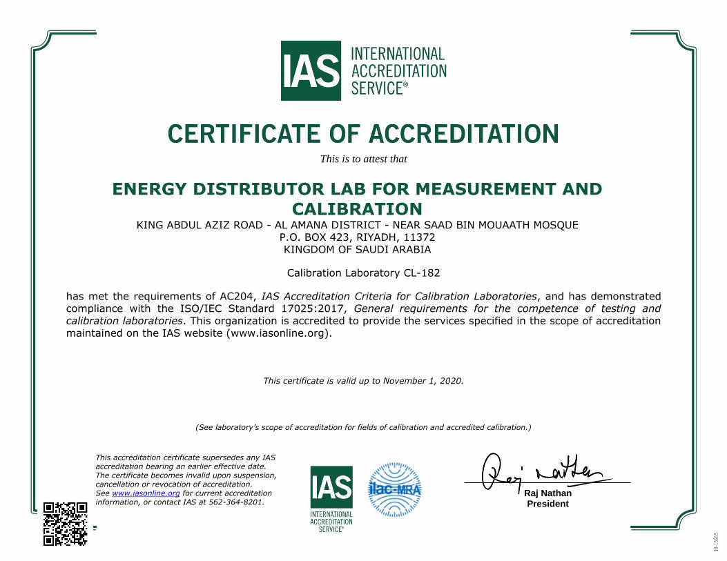
This is to attest that ENERGY DISTRIBUTOR LAB FOR MEASUREMENT AND CALIBRATION KING ABDUL AZIZ ROAD - AL AMANA DISTRICT - NEAR SAAD BIN MOUAATH MOSQUE P.O. BOX 423, RIYADH, 11372 KINGDOM OF SAUDI ARABIA Calibration Laboratory CL-182 has met the requirements of AC204, IAS Accreditation Criteria for Calibration Laboratories, and has demonstrated compliance with the ISO/IEC Standard 17025:2017, General requirements for the competence of testing and calibration laboratories. This organization is accredited to provide the services specified in the scope of accreditation maintained on the IAS website (www.iasonline.org). This certificate is valid up to November 1, 2020. (See laboratory’s scope of accreditation for fields of calibration and accredited calibration.) Raj Nathan President This accreditation certificate supersedes any IAS accreditation bearing an earlier effective date. The certificate becomes invalid upon suspension, cancellation or revocation of accreditation. See www.iasonline.org for current accreditation information, or contact IAS at 562-364-8201.
Transcript of ENERGY DISTRIBUTOR LAB FOR MEASUREMENT AND CALIBRATION · Calibration Laboratory CL-182 . has met...
This is to attest that
ENERGY DISTRIBUTOR LAB FOR MEASUREMENT AND CALIBRATION
KING ABDUL AZIZ ROAD - AL AMANA DISTRICT - NEAR SAAD BIN MOUAATH MOSQUE P.O. BOX 423, RIYADH, 11372 KINGDOM OF SAUDI ARABIA
Calibration Laboratory CL-182
has met the requirements of AC204, IAS Accreditation Criteria for Calibration Laboratories, and has demonstrated compliance with the ISO/IEC Standard 17025:2017, General requirements for the competence of testing and calibration laboratories. This organization is accredited to provide the services specified in the scope of accreditation
maintained on the IAS website (www.iasonline.org).
This certificate is valid up to November 1, 2020.
(See laboratory’s scope of accreditation for fields of calibration and accredited calibration.)
Raj Nathan President
This accreditation certificate supersedes any IAS accreditation bearing an earlier effective date. The certificate becomes invalid upon suspension, cancellation or revocation of accreditation. See www.iasonline.org for current accreditation information, or contact IAS at 562-364-8201.
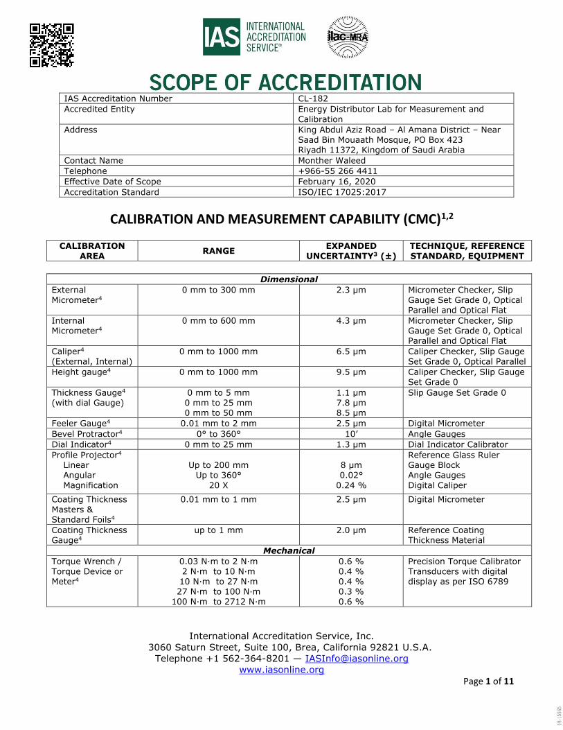
IAS Accreditation Number CL-182
Accredited Entity Energy Distributor Lab for Measurement and
Calibration
Address King Abdul Aziz Road – Al Amana District – Near Saad Bin Mouaath Mosque, PO Box 423 Riyadh 11372, Kingdom of Saudi Arabia
Contact Name Monther Waleed
Telephone +966-55 266 4411
Effective Date of Scope February 16, 2020
Accreditation Standard ISO/IEC 17025:2017
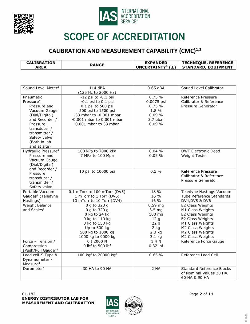
CALIBRATION AND MEASUREMENT CAPABILITY (CMC)1,2
CALIBRATION AREA
RANGE EXPANDED
UNCERTAINTY3 (±) TECHNIQUE, REFERENCE STANDARD, EQUIPMENT
International Accreditation Service, Inc.
3060 Saturn Street, Suite 100, Brea, California 92821 U.S.A.
Telephone +1 562-364-8201 — [email protected]
www.iasonline.org Page 1 of 11
Dimensional
External
Micrometer4
0 mm to 300 mm 2.3 µm Micrometer Checker, Slip
Gauge Set Grade 0, Optical Parallel and Optical Flat
Internal Micrometer4
0 mm to 600 mm 4.3 µm Micrometer Checker, Slip Gauge Set Grade 0, Optical Parallel and Optical Flat
Caliper4 (External, Internal)
0 mm to 1000 mm
6.5 µm
Caliper Checker, Slip Gauge Set Grade 0, Optical Parallel
Height gauge4 0 mm to 1000 mm
9.5 µm
Caliper Checker, Slip Gauge Set Grade 0
Thickness Gauge4 (with dial Gauge)
0 mm to 5 mm 0 mm to 25 mm 0 mm to 50 mm
1.1 µm 7.8 µm 8.5 µm
Slip Gauge Set Grade 0
Feeler Gauge4 0.01 mm to 2 mm 2.5 µm Digital Micrometer
Bevel Protractor4 0° to 360° 10’ Angle Gauges
Dial Indicator4 0 mm to 25 mm 1.3 μm Dial Indicator Calibrator
Profile Projector4 Linear Angular
Magnification
Up to 200 mm
Up to 360°
20 X
8 μm 0.02°
0.24 %
Reference Glass Ruler Gauge Block Angle Gauges
Digital Caliper
Coating Thickness
Masters & Standard Foils4
0.01 mm to 1 mm 2.5 µm Digital Micrometer
Coating Thickness Gauge4
up to 1 mm 2.0 μm Reference Coating Thickness Material
Mechanical
Torque Wrench / Torque Device or Meter4
0.03 N·m to 2 N·m 2 N·m to 10 N·m 10 N·m to 27 N·m 27 N·m to 100 N·m
100 N·m to 2712 N·m
0.6 % 0.4 % 0.4 % 0.3 % 0.6 %
Precision Torque Calibrator Transducers with digital display as per ISO 6789
CALIBRATION AND MEASUREMENT CAPABILITY (CMC)1,2
CALIBRATION AREA
RANGE EXPANDED
UNCERTAINTY3 (±) TECHNIQUE, REFERENCE STANDARD, EQUIPMENT
CL-182 Page 2 of 11 ENERGY DISTRIBUTOR LAB FOR MEASUREMENT AND CALIBRATION
Sound Level Meter4 114 dBA (125 Hz to 2000 Hz)
0.65 dBA Sound Level Calibrator
Pneumatic Pressure4
Pressure and Vacuum Gauge (Dial/Digital) and Recorder /
Pressure transducer / transmitter / Safety valve (Both in lab and at site)
-12 psi to -0.1 psi -0.1 psi to 0.1 psi
0.1 psi to 500 psi 500 psi to 1500 psi
-33 mbar to -0.001 mbar -0.001 mbar to 0.001 mbar
0.001 mbar to 33 mbar
0.75 % 0.0075 psi
0.75 % 1.8 % 0.09 % 3.7 µbar
0.09 %
Reference Pressure Calibrator & Reference
Pressure Generator
Hydraulic Pressure4 Pressure and Vacuum Gauge (Dial/Digital) and Recorder /
Pressure
transducer / transmitter / Safety valve
100 kPa to 7000 kPa 7 MPa to 100 Mpa
0.04 % 0.05 %
DWT Electronic Dead Weight Tester
10 psi to 10000 psi 0.5 %
Reference Pressure
Calibrator & Reference Pressure Generator
Portable Vacuum Gauges4 (Teledyne Hastings)
0.1 mTorr to 100 mTorr (DV5) 1 mTorr to 1 Torr (DV6)
10 mTorr to 10 Torr (DV4)
18 % 16 % 16 %
Teledyne Hastings Vacuum Tube Reference Standards DV4,DV5 & DV6
Weight Balance
and Scales4
0 g to 320 g
0 g to 320 g 0 kg to 24 kg 0 kg to 110 kg 0 kg to 150 kg Up to 500 kg
500 kg to 1000 kg 1000 kg to 9000 kg
0.59 mg
3.5 mg 100 mg
12 g 22 g 2 kg
2.3 kg 3.1 kg
E2 Class Weights
M1 Class Weights E2 Class Weights E2 Class Weights M1 Class Weights M2 Class Weights M2 Class Weights M2 Class Weights
Force – Tension /
Compression (Push/Pull Gauge)4
0 t 2000 N
0 lbf to 500 lbf
1.4 N
0.32 lbf
Reference Force Gauge
Load cell-S Type &
Dynamometer -Measure4
100 kgf to 20000 kgf
0.65 % Reference Load Cell
Durometer4 30 HA to 90 HA 2 HA Standard Reference Blocks of Nominal Values 30 HA, 60 HA & 90 HA
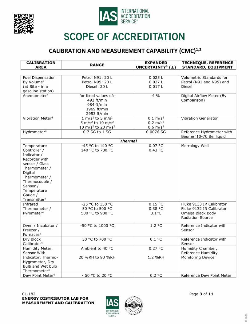
CALIBRATION AND MEASUREMENT CAPABILITY (CMC)1,2
CALIBRATION AREA
RANGE EXPANDED
UNCERTAINTY3 (±) TECHNIQUE, REFERENCE STANDARD, EQUIPMENT
CL-182 Page 3 of 11 ENERGY DISTRIBUTOR LAB FOR MEASUREMENT AND CALIBRATION
Fuel Dispensation By Volume4
(at Site - in a gasoline station)
Petrol N91: 20 L Petrol N95: 20 L
Diesel: 20 L
0.025 L 0.027 L
0.017 L
Volumetric Standards for Petrol (N91 and N95) and
Diesel
Anemometer4 for fixed values of: 492 ft/min
984 ft/min 1969 ft/min
2953 ft/min
4 % Digital Airflow Meter (By Comparison)
Vibration Meter4 1 m/s2 to 5 m/s2
5 m/s2 to 10 m/s2
10 m/s2 to 20 m/s2
0.1 m/s2 0.2 m/s2 0.6 m/s2
Vibration Generator
Hydrometer4 0.7 SG to 1 SG 0.0076 SG Reference Hydrometer with Baume '10-70 Be' liquid
Thermal
Temperature Controller /
Indicator / Recorder with sensor / Glass Thermometer / Digital
Thermometer /
Thermocouple / Sensor / Temperature Gauge / Transmitter4
-45 °C to 140 °C 140 °C to 700 °C
0.07 °C 0.43 °C
Metrology Well
Infrared
Thermometer / Pyrometer4
-25 °C to 150 °C
50 °C to 500 °C 500 °C to 980 °C
0.15 °C
0.38 °C 3.1°C
Fluke 9133 IR Calibrator
Fluke 9132 IR Calibrator Omega Black Body Radiation Source
Oven / Incubator / Freezer / Furnaces4
-50 °C to 1000 °C 1.2 °C Reference Indicator with Sensor
Dry Block Calibrator4
50 °C to 700 °C 0.1 °C Reference Indicator with Sensor
Humidity Meter, Sensor With Indicator, Thermo-
Hygrometer, Dry Bulb and Wet bulb Thermometer4
Ambient to 40 °C
20 %RH to 90 %RH
0.27 °C
1.2 %RH
Humidity Chamber, Reference Humidity Monitoring Device
Dew Point Meter4 - 50 °C to 20 °C 0.2 °C Reference Dew Point Meter
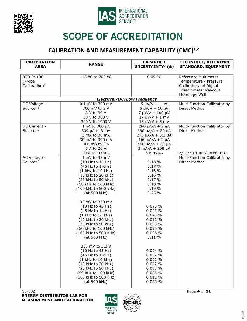
CALIBRATION AND MEASUREMENT CAPABILITY (CMC)1,2
CALIBRATION AREA
RANGE EXPANDED
UNCERTAINTY3 (±) TECHNIQUE, REFERENCE STANDARD, EQUIPMENT
CL-182 Page 4 of 11 ENERGY DISTRIBUTOR LAB FOR MEASUREMENT AND CALIBRATION
RTD Pt 100 (Probe
Calibration)4
-45 °C to 700 °C 0.09 °C Reference Multimeter Temperature / Pressure
Calibrator and Digital Thermometer Readout Metrology Well
Electrical/DC/Low Frequency
DC Voltage –
Source4,5
0.1 μV to 300 mV
300 mV to 3 V 3 V to 30 V
30 V to 300 V 300 V to 1000 V
5 µV/V + 1 µV
5 µV/V + 10 µV 7 µV/V + 100 µV 17 µV/V + 1 mV 15 µV/V + 5 mV
Multi-Function Calibrator by
Direct Method
DC Current -
Source4,5
1 nA to 300 μA
300 μA to 3 mA 3 mA to 30 mA
30 mA to 300 mA 300 mA to 3 A
3 A to 20 A 20 A to 1000 A
260 µA/A + 2 nA
690 µA/A + 20 nA 270 µA/A + 0.2 µA 160 µA/A + 2 µA 460 µA/A + 20 µA 3 mA/A + 200 µA
3.8 mA/A
Multi-Function Calibrator by
Direct Method 2/10/50 Turn Current Coil
AC Voltage - Source4,5
1 mV to 33 mV (10 Hz to 45 Hz) (45 Hz to 1 kHz) (1 kHz to 10 kHz)
(10 kHz to 20 kHz) (20 kHz to 50 kHz)
(50 kHz to 100 kHz) (100 kHz to 500 kHz)
(at 500 kHz)
33 mV to 330 mV (10 Hz to 45 Hz) (45 Hz to 1 kHz)
(1 kHz to 10 kHz) (10 kHz to 20 kHz) (20 kHz to 50 kHz) (50 kHz to 100 kHz) (100 kHz to 500 kHz)
(at 500 kHz)
330 mV to 3.3 V (10 Hz to 45 Hz) (45 Hz to 1 kHz) (1 kHz to 10 kHz) (10 kHz to 20 kHz) (20 kHz to 50 kHz)
(50 kHz to 100 kHz) (100 kHz to 500 kHz)
(at 500 kHz)
0.18 % 0.17 % 0.16 %
0.16 % 0.17 %
0.18 % 0.19 % 0.25 %
0.093 % 0.093 %
0.093 % 0.093 % 0.093 % 0.095 % 0.098 % 0.11 %
0.004 % 0.002 % 0.002 % 0.002 % 0.003 %
0.005 % 0.012 % 0.023 %
Multi-Function Calibrator by Direct Method
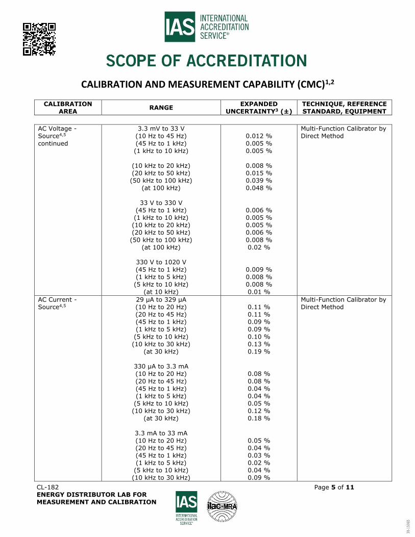
CALIBRATION AND MEASUREMENT CAPABILITY (CMC)1,2
CALIBRATION AREA
RANGE EXPANDED
UNCERTAINTY3 (±) TECHNIQUE, REFERENCE STANDARD, EQUIPMENT
CL-182 Page 5 of 11 ENERGY DISTRIBUTOR LAB FOR MEASUREMENT AND CALIBRATION
AC Voltage - Source4,5
continued
3.3 mV to 33 V (10 Hz to 45 Hz)
(45 Hz to 1 kHz) (1 kHz to 10 kHz)
(10 kHz to 20 kHz)
(20 kHz to 50 kHz) (50 kHz to 100 kHz)
(at 100 kHz)
33 V to 330 V
(45 Hz to 1 kHz) (1 kHz to 10 kHz) (10 kHz to 20 kHz) (20 kHz to 50 kHz)
(50 kHz to 100 kHz) (at 100 kHz)
330 V to 1020 V (45 Hz to 1 kHz) (1 kHz to 5 kHz) (5 kHz to 10 kHz)
(at 10 kHz)
0.012 %
0.005 % 0.005 %
0.008 %
0.015 % 0.039 % 0.048 %
0.006 % 0.005 % 0.005 % 0.006 %
0.008 % 0.02 %
0.009 % 0.008 % 0.008 %
0.01 %
Multi-Function Calibrator by Direct Method
AC Current - Source4,5
29 μA to 329 μA (10 Hz to 20 Hz) (20 Hz to 45 Hz) (45 Hz to 1 kHz) (1 kHz to 5 kHz)
(5 kHz to 10 kHz) (10 kHz to 30 kHz)
(at 30 kHz)
330 μA to 3.3 mA (10 Hz to 20 Hz)
(20 Hz to 45 Hz) (45 Hz to 1 kHz) (1 kHz to 5 kHz) (5 kHz to 10 kHz)
(10 kHz to 30 kHz) (at 30 kHz)
3.3 mA to 33 mA (10 Hz to 20 Hz) (20 Hz to 45 Hz) (45 Hz to 1 kHz) (1 kHz to 5 kHz) (5 kHz to 10 kHz) (10 kHz to 30 kHz)
0.11 % 0.11 % 0.09 % 0.09 %
0.10 % 0.13 % 0.19 %
0.08 %
0.08 % 0.04 % 0.04 % 0.05 %
0.12 % 0.18 %
0.05 % 0.04 % 0.03 % 0.02 % 0.04 % 0.09 %
Multi-Function Calibrator by Direct Method

CALIBRATION AND MEASUREMENT CAPABILITY (CMC)1,2
CALIBRATION AREA
RANGE EXPANDED
UNCERTAINTY3 (±) TECHNIQUE, REFERENCE STANDARD, EQUIPMENT
CL-182 Page 6 of 11 ENERGY DISTRIBUTOR LAB FOR MEASUREMENT AND CALIBRATION
AC Current - Source4,5
continued
3.3 mA to 33 mA (at 30 kHz)
33 mA to 330 mA (10 Hz to 20 Hz) (20 Hz to 45 Hz)
(45 Hz to 1 kHz) (1 kHz to 5 kHz) (5 kHz to 10 kHz)
(10 kHz to 30 kHz) (at 30 kHz)
330 mA to 1.1 A (10 Hz to 45 Hz) (45 Hz to 1 kHz)
(1 kHz to 5 kHz) (5 kHz to 10 kHz)
(at 10 kHz)
1.1 A to 3 A (10 Hz to 45 Hz) (45 Hz to 1 kHz)
(1 kHz to 5 kHz) (5 kHz to 10 kHz)
(at 10 kHz)
3 A to 20 A (45 Hz to 100 Hz) (100 Hz to 1 kHz)
(1 kHz to 5 kHz) (at 5 kHz)
20 A to 1000 A
(45 Hz to 1 kHz)
0.30 %
0.05 % 0.04 %
0.03 % 0.03 % 0.04 %
0.09 % 0.40 %
0.05 % 0.03 %
0.03 % 0.04 % 0.08 %
0.03 % 0.03 %
0.03 % 0.04 % 0.10 %
0.044 % 0.04 %
0.04 % 0.083 %
0.38 %
Multi-Function Calibrator by Direct Method
2/10/50 Turn Current Coil
Frequency - Source4,5
0.3 Hz to 1200 kHz 1.2 MHz to 2 MHz
0.002 % 0.004 %
Multi-Function Calibrator by Direct Method
Capacitance –
Source4,5 (100 Hz to 1 kHz)
220 pF to 400 pF
0.6 nF to 330 nF 0.33 μF to 330 μF
0.33 mF to 110 mF
5 %
0.006 % 0.011 %
0.064 %
Multi-Function Calibrator by
Direct Method
Energy Meter4 (50 Hz / 60 Hz)
1 Wh to 10 kWh 10 W to 10 kW 1 VA to 10 kVA 20 V to 300 V
500 mA to 100 A
0.75 Wh 0.17 % 0.17 % 0.011 % 0.054 %
Three Phase Reference Meter and Portable Power Source
CALIBRATION AND MEASUREMENT CAPABILITY (CMC)1,2
CALIBRATION AREA
RANGE EXPANDED
UNCERTAINTY3 (±) TECHNIQUE, REFERENCE STANDARD, EQUIPMENT
CL-182 Page 7 of 11 ENERGY DISTRIBUTOR LAB FOR MEASUREMENT AND CALIBRATION
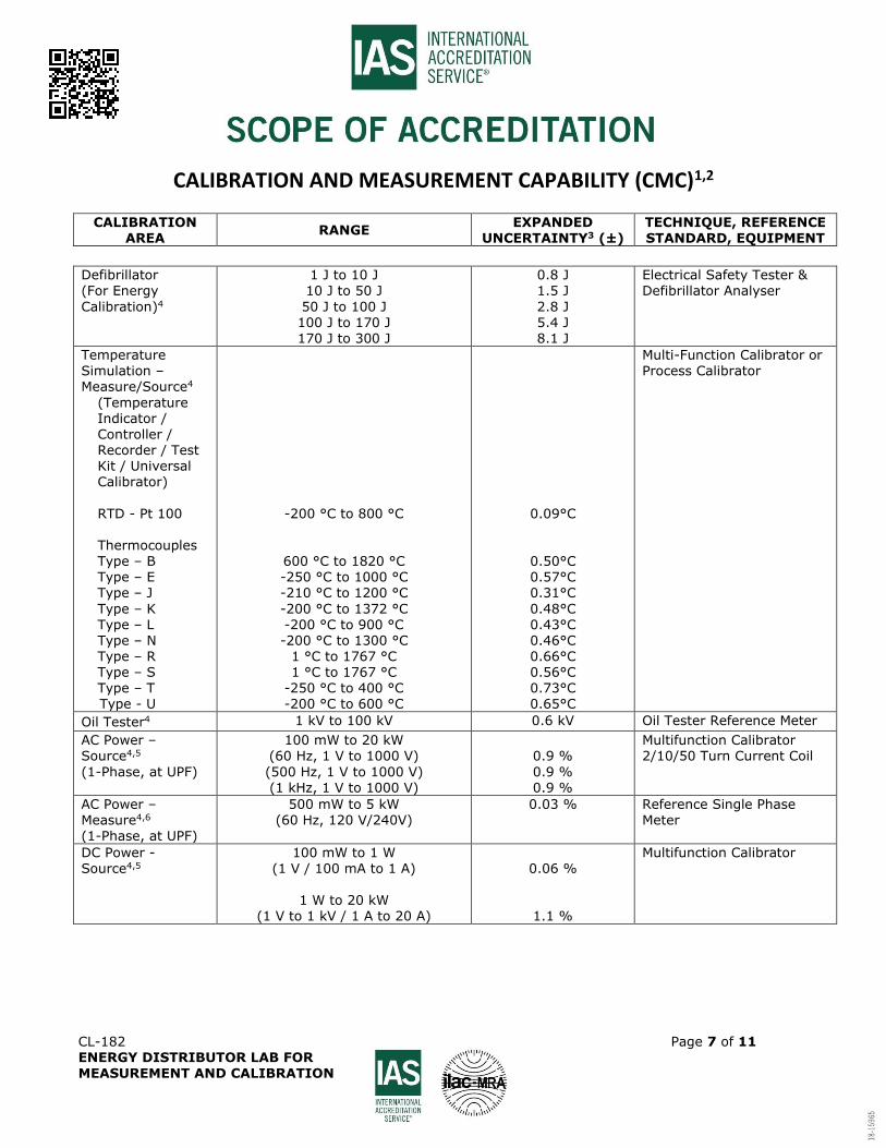
Defibrillator (For Energy
Calibration)4
1 J to 10 J 10 J to 50 J
50 J to 100 J 100 J to 170 J 170 J to 300 J
0.8 J 1.5 J
2.8 J 5.4 J 8.1 J
Electrical Safety Tester & Defibrillator Analyser
Temperature
Simulation – Measure/Source4
(Temperature Indicator / Controller / Recorder / Test Kit / Universal Calibrator)
RTD - Pt 100 Thermocouples Type – B Type – E Type – J
Type – K
Type – L Type – N Type – R Type – S Type – T Type - U
-200 °C to 800 °C
600 °C to 1820 °C -250 °C to 1000 °C -210 °C to 1200 °C
-200 °C to 1372 °C
-200 °C to 900 °C -200 °C to 1300 °C
1 °C to 1767 °C 1 °C to 1767 °C
-250 °C to 400 °C -200 °C to 600 °C
0.09°C
0.50°C 0.57°C 0.31°C
0.48°C
0.43°C 0.46°C 0.66°C 0.56°C 0.73°C 0.65°C
Multi-Function Calibrator or
Process Calibrator
Oil Tester4 1 kV to 100 kV 0.6 kV Oil Tester Reference Meter
AC Power – Source4,5
(1-Phase, at UPF)
100 mW to 20 kW (60 Hz, 1 V to 1000 V)
(500 Hz, 1 V to 1000 V) (1 kHz, 1 V to 1000 V)
0.9 %
0.9 % 0.9 %
Multifunction Calibrator 2/10/50 Turn Current Coil
AC Power – Measure4,6 (1-Phase, at UPF)
500 mW to 5 kW (60 Hz, 120 V/240V)
0.03 % Reference Single Phase Meter
DC Power -
Source4,5
100 mW to 1 W
(1 V / 100 mA to 1 A)
1 W to 20 kW (1 V to 1 kV / 1 A to 20 A)
0.06 %
1.1 %
Multifunction Calibrator
CALIBRATION AND MEASUREMENT CAPABILITY (CMC)1,2
CALIBRATION AREA
RANGE EXPANDED
UNCERTAINTY3 (±) TECHNIQUE, REFERENCE STANDARD, EQUIPMENT
CL-182 Page 8 of 11 ENERGY DISTRIBUTOR LAB FOR MEASUREMENT AND CALIBRATION
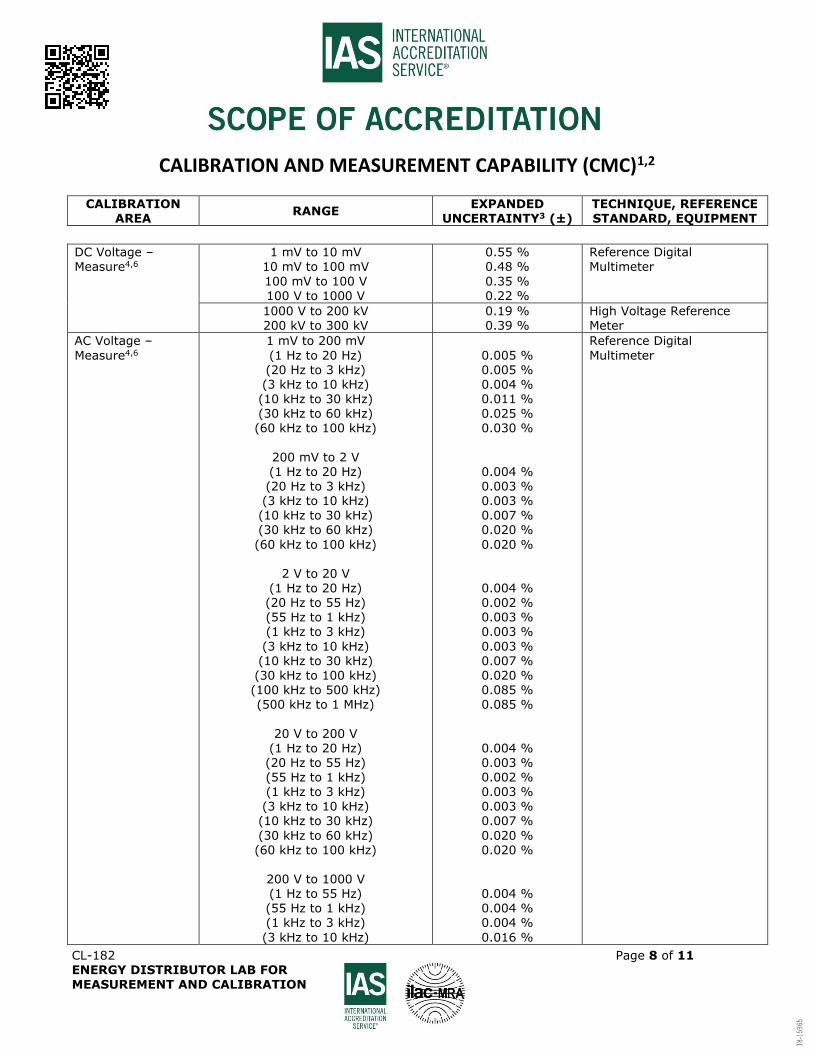
DC Voltage – Measure4,6
1 mV to 10 mV 10 mV to 100 mV
100 mV to 100 V 100 V to 1000 V
0.55 % 0.48 %
0.35 % 0.22 %
Reference Digital Multimeter
1000 V to 200 kV 200 kV to 300 kV
0.19 % 0.39 %
High Voltage Reference Meter
AC Voltage –
Measure4,6
1 mV to 200 mV
(1 Hz to 20 Hz) (20 Hz to 3 kHz) (3 kHz to 10 kHz) (10 kHz to 30 kHz) (30 kHz to 60 kHz) (60 kHz to 100 kHz)
200 mV to 2 V (1 Hz to 20 Hz) (20 Hz to 3 kHz) (3 kHz to 10 kHz) (10 kHz to 30 kHz) (30 kHz to 60 kHz)
(60 kHz to 100 kHz)
2 V to 20 V (1 Hz to 20 Hz) (20 Hz to 55 Hz) (55 Hz to 1 kHz) (1 kHz to 3 kHz)
(3 kHz to 10 kHz) (10 kHz to 30 kHz) (30 kHz to 100 kHz) (100 kHz to 500 kHz) (500 kHz to 1 MHz)
20 V to 200 V (1 Hz to 20 Hz) (20 Hz to 55 Hz) (55 Hz to 1 kHz) (1 kHz to 3 kHz)
(3 kHz to 10 kHz) (10 kHz to 30 kHz)
(30 kHz to 60 kHz) (60 kHz to 100 kHz)
200 V to 1000 V (1 Hz to 55 Hz) (55 Hz to 1 kHz) (1 kHz to 3 kHz)
(3 kHz to 10 kHz)
0.005 % 0.005 % 0.004 % 0.011 % 0.025 % 0.030 %
0.004 % 0.003 % 0.003 % 0.007 % 0.020 %
0.020 %
0.004 % 0.002 % 0.003 % 0.003 %
0.003 % 0.007 % 0.020 % 0.085 % 0.085 %
0.004 % 0.003 % 0.002 % 0.003 %
0.003 % 0.007 %
0.020 % 0.020 %
0.004 % 0.004 % 0.004 %
0.016 %
Reference Digital
Multimeter
CALIBRATION AND MEASUREMENT CAPABILITY (CMC)1,2
CALIBRATION AREA
RANGE EXPANDED
UNCERTAINTY3 (±) TECHNIQUE, REFERENCE STANDARD, EQUIPMENT
CL-182 Page 9 of 11 ENERGY DISTRIBUTOR LAB FOR MEASUREMENT AND CALIBRATION
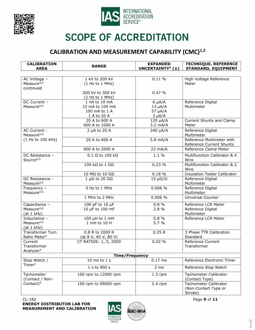
AC Voltage – Measure4,6
continued
1 kV to 200 kV (1 Hz to 1 MHz)
200 kV to 300 kV (1 Hz to 1 MHz)
0.11 %
0.47 %
High Voltage Reference Meter
DC Current –
Measure4,6
1 nA to 10 mA
10 mA to 100 mA 100 mA to 1 A
1 A to 20 A
6 µA/A
13 µA/A 57 µA/A
3 µA/A
Reference Digital
Multimeter
20 A to 600 A 600 A to 1000 A
120 µA/A 3.2 mA/A
Current Shunts and Clamp Meter
AC Current - Measure4,6
(1 Hz to 100 kHz)
2 μA to 20 A
240 µA/A Reference Digital Multimeter
20 A to 600 A 5.8 mA/A Reference Multimeter with Reference Current Shunts
600 A to 2000 A 23 mA/A Reference Clamp Meter
DC Resistance – Source4,5
0.1 Ω to 100 kΩ 1.1 % Multifunction Calibrator & 4 Wire
100 kΩ to 1 GΩ 0.23 % Multifunction Calibrator & 2 Wire
10 MΩ to 10 GΩ 0.18 % Insulation Tester Calibrator
DC Resistance - Measure4,6
1 μΩ to 20 GΩ 15 µΩ/Ω Reference Digital Multimeter
Frequency – Measure4,6
0 Hz to 1 MHz
0.006 % Reference Digital Multimeter
1 MHz to 2 MHz 0.006 % Universal Counter
Capacitance –
Measure4,6 (at 1 kHz)
100 pF to 10 μF
10 μF to 100 mF
0.8 %
2.8 %
Reference LCR Meter
Reference Digital Multimeter
Inductance – Measure4,6 (at 1 kHz)
100 μH to 1 mH 1 mH to 10 H
0.8 % 5.7 %
Reference LCR Meter
Transformer Turn Ratio Meter4
0.8 R to 2000 R (at 8 V, 40 V, 80 V)
0.25 R 3 Phase TTR Calibration Standard
Current Transformer
Analyzer4
CT RATIOS: 1, 5, 2000 0.02 % Reference Current Transformer
Time/Frequency
Stop Watch / Timer4
10 ms to 1 s 0.17 ms Reference Electronic Timer
1 s to 900 s 2 ms Reference Stop Watch
Tachometer
(Contact / Non–Contact)4
100 rpm to 12000 rpm 1.3 rpm Tachometer Calibrator
(Contact Type)
100 rpm to 99000 rpm 2.4 rpm Tachometer Calibrator (Non-Contact Type or Strobe)
CALIBRATION AND MEASUREMENT CAPABILITY (CMC)1,2
CALIBRATION AREA
RANGE EXPANDED
UNCERTAINTY3 (±) TECHNIQUE, REFERENCE STANDARD, EQUIPMENT
CL-182 Page 10 of 11 ENERGY DISTRIBUTOR LAB FOR MEASUREMENT AND CALIBRATION
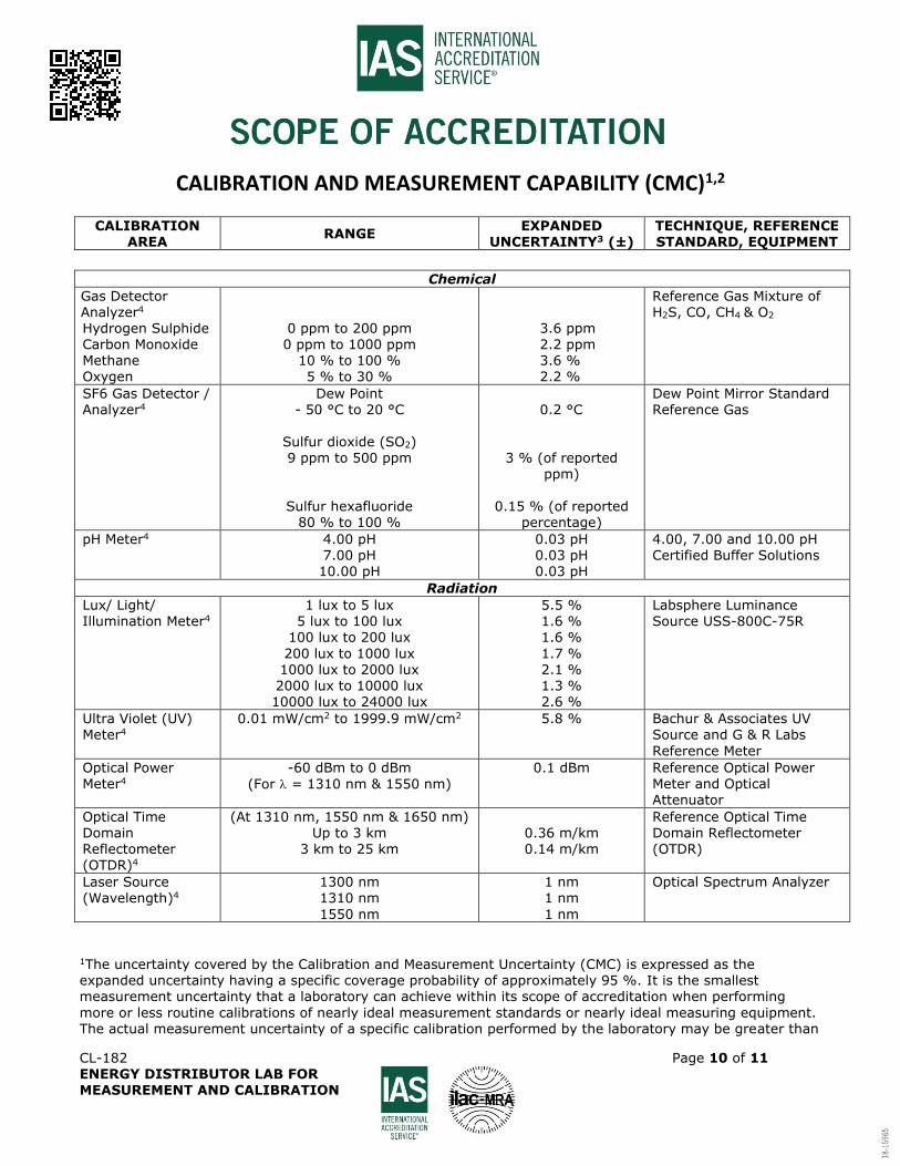
Chemical
Gas Detector Analyzer4 Hydrogen Sulphide Carbon Monoxide Methane
Oxygen
0 ppm to 200 ppm 0 ppm to 1000 ppm
10 % to 100 %
5 % to 30 %
3.6 ppm 2.2 ppm 3.6 %
2.2 %
Reference Gas Mixture of H2S, CO, CH4 & O2
SF6 Gas Detector / Analyzer4
Dew Point - 50 °C to 20 °C
Sulfur dioxide (SO2) 9 ppm to 500 ppm
Sulfur hexafluoride
80 % to 100 %
0.2 °C
3 % (of reported ppm)
0.15 % (of reported
percentage)
Dew Point Mirror Standard Reference Gas
pH Meter4
4.00 pH 7.00 pH 10.00 pH
0.03 pH 0.03 pH 0.03 pH
4.00, 7.00 and 10.00 pH Certified Buffer Solutions
Radiation
Lux/ Light/ Illumination Meter4
1 lux to 5 lux 5 lux to 100 lux
100 lux to 200 lux
200 lux to 1000 lux 1000 lux to 2000 lux 2000 lux to 10000 lux 10000 lux to 24000 lux
5.5 % 1.6 %
1.6 %
1.7 % 2.1 % 1.3 % 2.6 %
Labsphere Luminance Source USS-800C-75R
Ultra Violet (UV) Meter4
0.01 mW/cm2 to 1999.9 mW/cm2 5.8 % Bachur & Associates UV Source and G & R Labs
Reference Meter
Optical Power Meter4
-60 dBm to 0 dBm
(For = 1310 nm & 1550 nm)
0.1 dBm Reference Optical Power Meter and Optical Attenuator
Optical Time Domain Reflectometer (OTDR)4
(At 1310 nm, 1550 nm & 1650 nm) Up to 3 km
3 km to 25 km
0.36 m/km 0.14 m/km
Reference Optical Time Domain Reflectometer (OTDR)
Laser Source (Wavelength)4
1300 nm 1310 nm
1550 nm
1 nm 1 nm
1 nm
Optical Spectrum Analyzer
1The uncertainty covered by the Calibration and Measurement Uncertainty (CMC) is expressed as the expanded uncertainty having a specific coverage probability of approximately 95 %. It is the smallest measurement uncertainty that a laboratory can achieve within its scope of accreditation when performing
more or less routine calibrations of nearly ideal measurement standards or nearly ideal measuring equipment. The actual measurement uncertainty of a specific calibration performed by the laboratory may be greater than
CALIBRATION AND MEASUREMENT CAPABILITY (CMC)1,2
CALIBRATION AREA
RANGE EXPANDED
UNCERTAINTY3 (±) TECHNIQUE, REFERENCE STANDARD, EQUIPMENT
CL-182 Page 11 of 11 ENERGY DISTRIBUTOR LAB FOR MEASUREMENT AND CALIBRATION
that provided in the CMC due to the behavior of the customer’s device and to influences from the circumstances of the specific calibration. 2If information in this CMC is presented in non-SI units, the conversion factors stated in NIST Special Publication 811 “Guide for the Use of the International System of Units (SI)” apply. 3When uncertainty is stated in relative terms (such as percent, a multiplier expressed as a decimal fraction or in scientific notation), it is in relation to instrument reading or instrument output, as appropriate, unless otherwise indicated. 4Calibration for this parameter/calibration item is available at the laboratory or at customer site. 5Capability is suitable for the calibration of measuring devices in the stated ranges.
6Capability is suitable for the calibration of devices intended to generate the measurand in the stated ranges.
SG = specific gravity
UPF = unity power factor
R = turn ratio
ppm = parts per million
HA = Shore Hardness Scale A