
ENERGY CONSUMPTION ANALYSES OF FREQUENTLY-USED …
96
The Pennsylvania State University The Graduate School College of Engineering ENERGY CONSUMPTION ANALYSES OF FREQUENTLY-USED HVAC SYSTEM TYPES IN HIGH PERFORMANCE OFFICE BUILDINGS A Thesis in Architectural Engineering by Liusheng Yan 2014 Liusheng Yan Submitted in Partial Fulfillment of the Requirements for the Degree of Master of Science May 2014
Transcript of ENERGY CONSUMPTION ANALYSES OF FREQUENTLY-USED …

The Pennsylvania State University
The Graduate School
College of Engineering
ENERGY CONSUMPTION ANALYSES OF FREQUENTLY-USED HVAC SYSTEM
TYPES IN HIGH PERFORMANCE OFFICE BUILDINGS
A Thesis in
Architectural Engineering
by
Liusheng Yan
2014 Liusheng Yan
Submitted in Partial Fulfillment
of the Requirements
for the Degree of
Master of Science
May 2014

ii
The thesis of Liusheng Yan was reviewed and approved* by the following:
Jelena Srebric
Professor of Architectural Engineering
Professor of Mechanical Engineering
Thesis Advisor
Chimay Anumba
Professor of Architectural Engineering
Head of the Department of Architectural Engineering
Stephan Treado
Associate Professor of Architectural Engineering
*Signatures are on file in the Graduate School

iii
ABSTRACT
The high energy consumption of heating, ventilation and air-conditioning (HVAC)
systems in commercial buildings is a hot topic. Office buildings, a typical building set of
commercial buildings, have also drawn enormous attention from researchers, facility managers,
designers and building owners due to high HVAC energy consumptions. Office buildings have a
set of frequently-used HVAC systems. These HVAC systems might have different energy
consumption patterns. High performance office buildings narrow the scope of testing this
hypothesis. Thus, the main objective of this thesis is to identify the frequently-used HVAC
system types for high performance office buildings and enable them in the energy consumption
analyses.
As a good representative of high performance buildings, a group of 134 LEED NC
(Leadership in Energy Efficient Design for New Construction & Major Renovations) certified
office buildings provide important resources to explore the frequently-used HVAC system types
in high performance office buildings. Frequently-used proposed HVAC systems are defined by
their frequencies in this valuable building sample.
The energy consumption analyses will go through each frequently-used proposed HVAC
system type. The energy consumption analyses explore (1) the energy consumption
characteristics focusing on proposed design cases and (2) energy saving characteristics from
baseline to proposed cases. Also from these 134 LEED certified office buildings, three clusters of
low, medium, and high energy use intensity have been identified as integrating both the building
size characteristics and total energy consumption patterns. Clusters classification provides a
further approach to compare the energy consumption patterns.
An actual large size office building in Philadelphia is selected as the case study to
demonstrate an energy consumption pattern. The well calibrated building model offers an ideal

iv
opportunity to test the energy consumption difference if it is changed to another HVAC system
type. Further simulations of lighting load reduction and envelop system upgrade are also possible.
These energy consumption patterns in high performance buildings pointed out not only the key
areas that affect the energy consumption characteristics but also the directions that lead to
potential energy savings for retrofit in low performance office buildings.
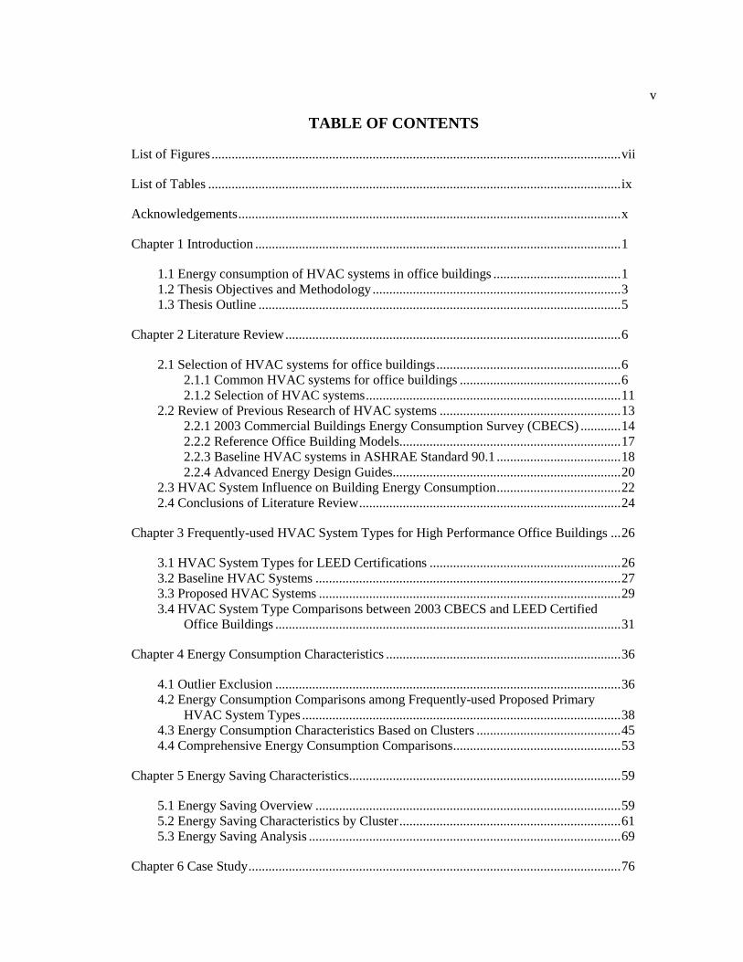
v
TABLE OF CONTENTS
List of Figures .......................................................................................................................... vii
List of Tables ........................................................................................................................... ix
Acknowledgements .................................................................................................................. x
Chapter 1 Introduction ............................................................................................................. 1
1.1 Energy consumption of HVAC systems in office buildings ...................................... 1 1.2 Thesis Objectives and Methodology .......................................................................... 3 1.3 Thesis Outline ............................................................................................................ 5
Chapter 2 Literature Review .................................................................................................... 6
2.1 Selection of HVAC systems for office buildings ....................................................... 6 2.1.1 Common HVAC systems for office buildings ................................................ 6 2.1.2 Selection of HVAC systems ............................................................................ 11
2.2 Review of Previous Research of HVAC systems ...................................................... 13 2.2.1 2003 Commercial Buildings Energy Consumption Survey (CBECS) ............ 14 2.2.2 Reference Office Building Models.................................................................. 17 2.2.3 Baseline HVAC systems in ASHRAE Standard 90.1 ..................................... 18 2.2.4 Advanced Energy Design Guides .................................................................... 20
2.3 HVAC System Influence on Building Energy Consumption ..................................... 22 2.4 Conclusions of Literature Review .............................................................................. 24
Chapter 3 Frequently-used HVAC System Types for High Performance Office Buildings ... 26
3.1 HVAC System Types for LEED Certifications ......................................................... 26 3.2 Baseline HVAC Systems ........................................................................................... 27 3.3 Proposed HVAC Systems .......................................................................................... 29 3.4 HVAC System Type Comparisons between 2003 CBECS and LEED Certified
Office Buildings ....................................................................................................... 31
Chapter 4 Energy Consumption Characteristics ...................................................................... 36
4.1 Outlier Exclusion ....................................................................................................... 36 4.2 Energy Consumption Comparisons among Frequently-used Proposed Primary
HVAC System Types ............................................................................................... 38 4.3 Energy Consumption Characteristics Based on Clusters ........................................... 45 4.4 Comprehensive Energy Consumption Comparisons .................................................. 53
Chapter 5 Energy Saving Characteristics................................................................................. 59
5.1 Energy Saving Overview ........................................................................................... 59 5.2 Energy Saving Characteristics by Cluster .................................................................. 61 5.3 Energy Saving Analysis ............................................................................................. 69
Chapter 6 Case Study ............................................................................................................... 76

vi
6.1 Building and HVAC System Description .................................................................. 76 6.2 HVAC System Change .............................................................................................. 78 6.3 Lighting Load Reduction and Envelop Upgrade ........................................................ 78
Chapter 7 Conclusions and Future Work ................................................................................. 81
7.1 Thesis Conclusions .................................................................................................... 81 7.2 Future Work ............................................................................................................... 83
References ................................................................................................................................ 84
vii
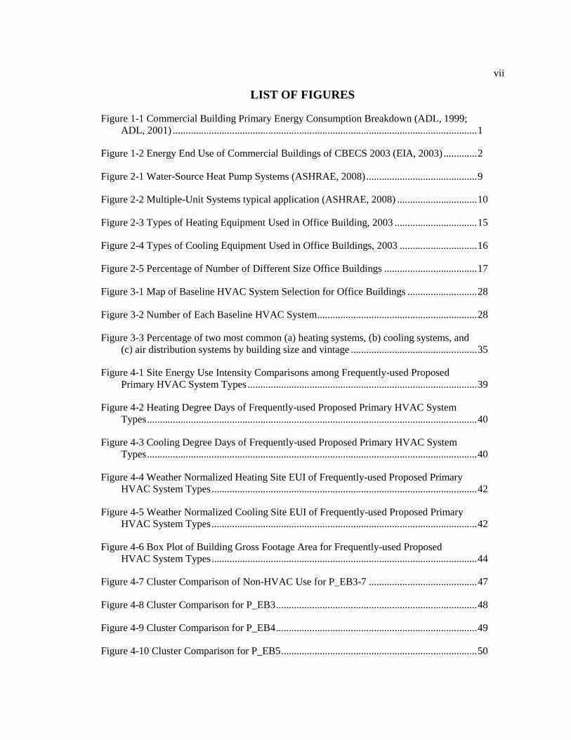
LIST OF FIGURES
Figure 1-1 Commercial Building Primary Energy Consumption Breakdown (ADL, 1999;
ADL, 2001) ...................................................................................................................... 1
Figure 1-2 Energy End Use of Commercial Buildings of CBECS 2003 (EIA, 2003) ............. 2
Figure 2-1 Water-Source Heat Pump Systems (ASHRAE, 2008) ........................................... 9
Figure 2-2 Multiple-Unit Systems typical application (ASHRAE, 2008) ............................... 10
Figure 2-3 Types of Heating Equipment Used in Office Building, 2003 ................................ 15
Figure 2-4 Types of Cooling Equipment Used in Office Buildings, 2003 .............................. 16
Figure 2-5 Percentage of Number of Different Size Office Buildings .................................... 17
Figure 3-1 Map of Baseline HVAC System Selection for Office Buildings ........................... 28
Figure 3-2 Number of Each Baseline HVAC System .............................................................. 28
Figure 3-3 Percentage of two most common (a) heating systems, (b) cooling systems, and
(c) air distribution systems by building size and vintage ................................................. 35
Figure 4-1 Site Energy Use Intensity Comparisons among Frequently-used Proposed
Primary HVAC System Types ......................................................................................... 39
Figure 4-2 Heating Degree Days of Frequently-used Proposed Primary HVAC System
Types ................................................................................................................................ 40
Figure 4-3 Cooling Degree Days of Frequently-used Proposed Primary HVAC System
Types ................................................................................................................................ 40
Figure 4-4 Weather Normalized Heating Site EUI of Frequently-used Proposed Primary
HVAC System Types ....................................................................................................... 42
Figure 4-5 Weather Normalized Cooling Site EUI of Frequently-used Proposed Primary
HVAC System Types ....................................................................................................... 42
Figure 4-6 Box Plot of Building Gross Footage Area for Frequently-used Proposed
HVAC System Types ....................................................................................................... 44
Figure 4-7 Cluster Comparison of Non-HVAC Use for P_EB3-7 .......................................... 47
Figure 4-8 Cluster Comparison for P_EB3 .............................................................................. 48
Figure 4-9 Cluster Comparison for P_EB4 .............................................................................. 49
Figure 4-10 Cluster Comparison for P_EB5 ............................................................................ 50

viii
Figure 4-11 Cluster Comparison for P_EB6 ............................................................................ 51
Figure 4-12 Cluster Comparison for P_EB7 ............................................................................ 52
Figure 4-13 Source Energy Use Intensity Comparisons among Frequently-used Proposed
Primary HVAC System Types ......................................................................................... 54
Figure 4-14 Comparisons of (a) heating site EUI and (b) heating source EUI in
frequently-used proposed HVAC systems ....................................................................... 55
Figure 4-15 Comparisons of (a) weather normalized heating source EUI and (b) weather
normalized cooling source EUI in frequently-used proposed HVAC systems ................ 57
Figure 5-1 Box Plot of Energy Saving by Cluster ................................................................... 60
Figure 5-2 Box Plot of Proposed Non-HVAC EUI by Cluster ................................................ 61
Figure 5-4 HVAC Saving in Low Energy Cluster ................................................................... 62
Figure 5-4 Energy Saving in Medium Energy Cluster ............................................................ 68
Figure 5-5 Energy Saving in High Energy Cluster .................................................................. 68
Figure 5-6 Average Energy Saving Comparisons of Frequently-used HVAC System
Types in Different Clusters .............................................................................................. 69
Figure 5-8 Workflow of Multiple Regression Analysis ........................................................... 71
Figure 6-1 Case Study Building (Credit: Google Maps) ......................................................... 77
Figure 6-2 Screenshot of Energy Model for the Case Study Building .................................... 77
Figure 6-3 Energy Consumption Comparisons of Case Study ................................................ 79

ix
LIST OF TABLES
Table 2-1 Main Characteristics Comparisons of Decentralized systems and Central
Systems ............................................................................................................................ 7
Table 2-2 Issues considered for HVAC system selection ........................................................ 12
Table 2-3 Heating and Cooling Equipment in 2003 CBECS ................................................... 14
Table 2-4 Reference HVAC systems from PNNL ................................................................... 17
Table 2-5 Baseline HVAC System Types................................................................................ 19
Table 2-6 Baseline HVAC System Description ....................................................................... 19
Table 2-7 HVAC Systems Recommendations ......................................................................... 21
Table 3-1 Building Size Distribution ....................................................................................... 29
Table 3-2 General HVAC System Category to Identify Proposed HVAC Systems ................ 29
Table 3-3 Identified Proposed HVAC Systems ....................................................................... 30
Table 4-1 Identified Proposed HVAC Systems (With Outlier Quantity) ................................ 37
Table 4-2 Applications of Frequently-used HVAC System Types .......................................... 45
Table 4-2 Cluster Distribution of Frequently-used Proposed HVAC systems ........................ 46
Table 5-1 Percentage of buildings with each energy end use saving dominated in each
cluster ............................................................................................................................... 62
Table 5-2 HVAC System Type Modification Trend by Cluster .............................................. 66
Table 5-3 Percentage Difference of Investigated Parameters in Three Clusters ...................... 70
Table 5-4 Results of Multiple Regression Analysis in Clusters and Frequently-used
HVAC System Types ....................................................................................................... 73
Table 5-5 Results of Multiple Regression Analysis in Subset of Buildings of Each
Frequently-used HVAC System Types ............................................................................ 74
Table 6-1 Energy consumption of Different HVAC System Types ........................................ 78
Table 6-2 Energy consumption of Further Lighting Load Reduction and Envelop
Upgrade ............................................................................................................................ 80

x
ACKNOWLEDGEMENTS
The first and the most important person I would like to thank is my adviser, Dr. Srecric.
She shows great patience, knowledgeable guidance and continuous encourage to me, which is a
lifelong priceless treasure for me.
I feel great grateful to Mohammad for helping me move forward with research work,
course work, warm concern about me as a family member.
I also appreciate the contribution and support from Matthew, Ibrahim and Seon, Jiying
and other group members.
The Energy Efficient Buildings HUB has provided financial support for this work.
The last but also quite important people are my parents, Jiehua Yan and Ling Chen, and
all my friends who kindly helped me go through all the tough time. Thank you all.
Chapter 1
Introduction
1.1 Energy consumption of HVAC systems in office buildings
Heating, ventilation and air conditioning (HVAC) systems play an important role to
provide indoor thermal comfort and basic indoor air quality for building occupants while aiming
to minimize energy consumption of the building. Energy consumption of HVAC systems is a
very important part of building energy consumption and has received great attention in the U.S.
HVAC systems in commercial buildings consumed a total of 4.5 quads of primary energy in
1995. That is about 30% of the whole primary energy consumption in roughly 59 billion square
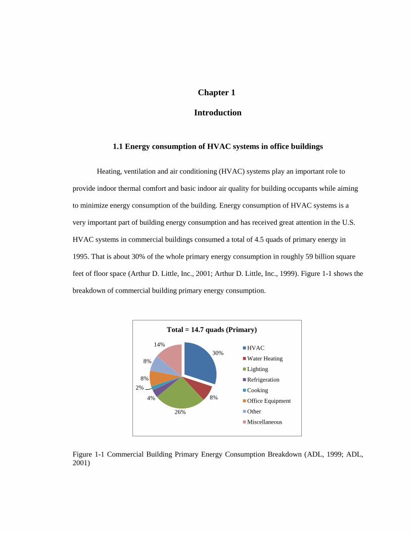
feet of floor space (Arthur D. Little, Inc., 2001; Arthur D. Little, Inc., 1999). Figure 1-1 shows the
breakdown of commercial building primary energy consumption.
Figure 1-1 Commercial Building Primary Energy Consumption Breakdown (ADL, 1999; ADL,
2001)
30%
8%
26%
4%
2%
8%
8%
14%
Total = 14.7 quads (Primary)
HVAC
Water Heating
Lighting
Refrigeration
Cooking
Office Equipment
Other
Miscellaneous

2
The Energy Information Administration (EIA) continuously conducts the Commercial
Buildings Energy Consumption Survey (CBECS) and produces the results about commercial
building information and energy consumption. According to the 2003 CBECS, about half of the
energy consumed in commercial buildings was used for HVAC system (including heating,
cooling, and ventilation) (EIA, 2006), accounting for around 20% of total energy consumption
(Perez-Lombard, Ortiz, & Pout, 2008; U.S. DOE, 2010). Figure 1-2 presents the energy end use
of commercial buildings of the 2003 CBECS. The enormous HVAC system energy consumption
in commercial buildings and its particularly significant growth of energy use draw more and more
focus from researchers, facility managers, designers and building owners.
Figure 1-2 Energy End Use of Commercial Buildings of CBECS 2003 (EIA, 2003)
Office buildings comprise a large portion of commercial buildings and are one of those
major energy-using building categories (Arthur D. Little, Inc., 2001). From the 1995 CBECS,
office buildings accounted for 17% of all commercial buildings floor space, which were about 10
billion square feet (EIA, 1998). While in the 2003 CBECS, office buildings accounted for 17
percent of total commercial buildings in the U.S., which comprised more than 12 billion square
36%
21% 8%
8%
7%
6%
3% 2% 1%
9%
Space Heating
Lighting
Cooling
Water Heating
Ventilation
Refrigeration
Cooking
Computers
Office Equipment

3
feet of floor space (EIA, 2006). Even nowadays, office buildings are still considered to be one of
the major categories of commercial buildings. This prevalence of office building space type and
the significance of HVAC systems on the energy consumption of buildings in the CBECS
database render office buildings as a special space type. Office buildings have the highest HVAC
energy use, with a medium amount of energy use intensity (85 to 110 kBtu/ft2), but represent a
large amount of commercial building floorspace. Therefore, in order to investigate the high
HVAC energy use in office buildings, high performance office buildings help to narrow the scope
and provide valuable resources. The frequently-used HVAC system types in those high
performance office buildings are selected to analyze the energy consumptions.
1.2 Thesis Objectives and Methodology
The hypothesis is “High performance office buildings have frequently-used HVAC system
types that result in different energy consumption patterns.” The main objective of this thesis is to
identify the frequently-used HVAC system types for high performance office buildings and
enable them in the energy consumption analyses. As a good representative of high performance
buildings, 134 LEED NC (Leadership in Energy Efficient Design for New Construction & Major
Renovations) certified office buildings provide important resources to explore the frequently-used
HVAC system types in high performance office buildings.
Four main research activities are:
1. Identify the proposed primary HVAC system types for LEED certified office buildings.
2. Analyze the energy consumption characteristics for frequently-used HVAC system
types of LEED certified office buildings.
3. Analyze the energy saving of frequently-used proposed HVAC system types for LEED
certified office buildings in three energy intensity clusters.
4
4. Justify the energy consumption patterns of different HVAC system types through a
case study of an actual office building.
The first question would be what are the frequently-used HVAC system types for higher
performance office buildings? Several important literatures provide the commonly-used HVAC
systems for office buildings, including system characteristics, applications, and design
considerations. As a good representative of high performance buildings, 134 LEED NC
(Leadership in Energy Efficient Design for New Construction & Major Renovations) certified
office buildings provide important resources to explore the frequently-used HVAC system types
in high performance office buildings. Based on three basic components of HVAC systems:
ventilation, heating, and cooling, the proposed HVAC system types are identified. These systems
are similar to the baseline HVAC type configurations in ASHRAE Standard 90.1. Frequently-
used proposed HVAC systems are defined by their frequencies in this valuable building sample.
The second question is how to enable these frequently-used HVAC system types in
energy consumption analyses? This study focuses on two main categories of total energy use,
HVAC and Non-HVAC. All lighting, service hot water, and process consumption are included
together as Non-HVAC use; while the study will go to three detail HVAC end uses (heating,
cooling, and fan and pump). The energy consumption analyses will go through each frequently-
used proposed HVAC system type. The energy consumption analyses explore (1) the energy
consumption characteristics in proposed design cases, and (2) energy saving characteristics from
baseline to proposed cases. Also from these 134 LEED certified office buildings, three clusters of
low, medium, and high energy use intensity have been identified as integrating both the building
size characteristics and total energy consumption patterns. Clusters classification provides a
further approach to compare the energy consumption patterns.
Built in 1973, an actual large size office building in Philadelphia is selected as the case
study to compare with high LEED certified office buildings of using the same HVAC system

5
type. The well calibrated case study building model offers an ideal opportunity to test the energy
consumption difference if it is changed to another HVAC system type. Further simulations of
lighting load reduction and envelop system upgrade are also possible.
1.3 Thesis Outline
The thesis is divided into seven chapters. Chapter 1 briefly introduces the background
information, this research hypothesis, objectives and methodology. Chapter 2 explores the
literatures to obtain the common HVAC systems of office buildings and their energy
consumption characteristics. Chapter 3 describes the identification effort of identifying the
frequently-used proposed HVAC system types of 134 LEED NC certified office buildings.
Chapter 4 compares the energy consumption of those frequently-used proposed HVAC system
types. Three energy intensity clusters provide a further approach for energy consumption
comparisons. Chapter 5 focuses on the energy saving characteristics of those frequently-used
proposed HVAC systems in different clusters by comparing with their baseline energy use.
Chapter 6 conducts a case study to demonstrate the energy consumption pattern and simulates the
energy saving cases. Finally, Chapter 7 summarizes the work and the recommendations for future
research studies.

Chapter 2
Literature Review
The literature review mainly focuses on three parts: (1) selection of HVAC systems for
office buildings; (2) previous research focusing on HVAC systems; (3) HVAC system’s influence
on building energy consumption.
2.1 Selection of HVAC systems for office buildings
2.1.1 Common HVAC systems for office buildings
ASHRAE Handbook – HVAC Equipment and Systems has discussed types of HVAC
systems. Common HVAC systems for commercial buildings are a main focus in this handbook.
Although typical HVAC systems for office buildings are not particularly specified, common
HVAC systems that are used in office buildings can be learnt regarding system characteristics,
design consideration, common application and other aspects.
Central systems and decentralized systems are two main HVAC system configurations.
Central systems typically use chilled water and extensive ductwork for air distribution to serve
multiple spaces, while decentralized systems use refrigerant to cool the air, which is called DX
cooling, to serve a single space or small spaces (Continuing Education and Development, Inc.).
For most small to mid-size installations, decentralized cooling and heating are usually
preferable to centralized systems. While central cooling and heating systems are particularly
common in very large office buildings or where there is a high density of energy use. The
advantages and disadvantages of these two systems are listed in this ASHRAE Handbook
7
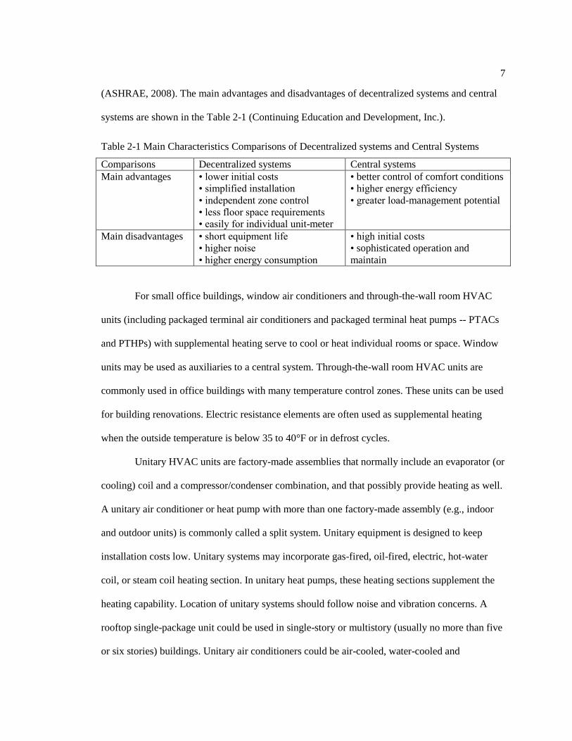
(ASHRAE, 2008). The main advantages and disadvantages of decentralized systems and central
systems are shown in the Table 2-1 (Continuing Education and Development, Inc.).
Table 2-1 Main Characteristics Comparisons of Decentralized systems and Central Systems
Comparisons Decentralized systems Central systems
Main advantages • lower initial costs
• simplified installation
• independent zone control
• less floor space requirements
• easily for individual unit-meter
• better control of comfort conditions
• higher energy efficiency
• greater load-management potential
Main disadvantages • short equipment life
• higher noise
• higher energy consumption
• high initial costs
• sophisticated operation and
maintain
For small office buildings, window air conditioners and through-the-wall room HVAC
units (including packaged terminal air conditioners and packaged terminal heat pumps -- PTACs
and PTHPs) with supplemental heating serve to cool or heat individual rooms or space. Window
units may be used as auxiliaries to a central system. Through-the-wall room HVAC units are
commonly used in office buildings with many temperature control zones. These units can be used
for building renovations. Electric resistance elements are often used as supplemental heating
when the outside temperature is below 35 to 40°F or in defrost cycles.
Unitary HVAC units are factory-made assemblies that normally include an evaporator (or
cooling) coil and a compressor/condenser combination, and that possibly provide heating as well.
A unitary air conditioner or heat pump with more than one factory-made assembly (e.g., indoor
and outdoor units) is commonly called a split system. Unitary equipment is designed to keep
installation costs low. Unitary systems may incorporate gas-fired, oil-fired, electric, hot-water
coil, or steam coil heating section. In unitary heat pumps, these heating sections supplement the
heating capability. Location of unitary systems should follow noise and vibration concerns. A
rooftop single-package unit could be used in single-story or multistory (usually no more than five
or six stories) buildings. Unitary air conditioners could be air-cooled, water-cooled and
8
evaporatively-cooled based on heat rejection types. Unitary heat pumps systems can be classified
as air-source heat pumps (ASHPs), water source heat pump systems, and geothermal heat pumps
(or ground-source heat pumps, GSHPs). GSHPs have a variety of system configurations, such as
water-loop heat pump systems, groundwater heat pump systems, closed-loop surface-water heat
pump systems, surface-water heat pump systems and ground-coupled heat pump systems (see
Figure 2-1). The water-loop heat pump system and closed-loop surface-water heat pump system
were introduced, and the efficient water-loop heat pump systems were analyzed (McQuay
International, 2002). Factors that could influence the type of unitary systems are size, shape, and
function of the building; availability and cost of energy; building aesthetics (equipment located
outdoors); and space available for equipment.

9
Figure 2-1 Water-Source Heat Pump Systems (ASHRAE, 2008)
Multiple-unit systems using single-zone unitary systems for building core areas, for
example interior working areas, computer rooms, or other spaces requiring continual cooling, are
popular for office buildings. Two typical configurations of this system (shown in Figure 2-2) are
that (1) unitary systems are used for the core zones to supplement perimeter packaged terminal
units; (2) one unit is used to precondition outside air for a group of zone units. Also unitary self-
contained units are excellent for renovation. Units of less than 20 tons of cooling capacity are
typically constant-volume units. VAV distribution may be accomplished on these units with a
bypass damper that allows excess supply air to bypass to the return air duct.

10
Figure 2-2 Multiple-Unit Systems typical application (ASHRAE, 2008)
Light commercial split system consists of an indoor unit and an outdoor unit. The indoor
unit includes evaporator coils, economizer coils, heating coils, filters, and valves, while the
outdoor condensing unit has compressors and condenser coils. The split system is usually
equipped with air distribution and temperature control. Either a water-cooled condenser, integral
air-cooled condenser, or remote air-cooled condenser is commonly used in small projects of
single-story or low-rise buildings with variable occupancy schedules. Fan operation with VAV
control or system when applied with VAV terminals provides great control and individual zone
control.
When coupled with terminal boxes or fan-powered terminal boxes, commercial self-
contained VAV units are popular for their energy savings, individual zone control, and acoustic
benefits. The heating in these units is often provided by hot-water coils, electric resistance or a
fuel-fired heat exchanger.
Commercial outdoor packaged systems made by factory-standard as central-station
equipment for single-zone or multi-zone are satisfactory for small and medium-sized office

11
buildings. The custom system can even serve for large projects with more flexibility, which will
increase initial cost but can be justified by life-cycle cost analyses and configured to satisfy
almost any requirement. The heating equipment is fuel-fired heating and electric heating or even
equipped with a boiler if it is a custom system.
A central plant provides heating and cooling and distributes them to end use for thermal
exchange and air conditioning. The refrigeration equipment of a central cooling plant may be
vapor-compression refrigeration cycle chillers, or absorption-cycle chillers, or the combination of
these chillers. The heat reject system could be cooling towers, air-cooled condensers, evaporative
condensers, or some other combinations. Central heating plants basically use boilers. Low rise
office buildings usually use a VAV system or CAV system in the interior zones or hydronic
system at perimeter. While high-rise office buildings usually have a central CAV system for the
core zone and a VAV system or hydronic system at the perimeter.
2.1.2 Selection of HVAC systems
This part presents how HVAC systems are usually selected. Basically, the functions of
HVAC systems are to provide an acceptable level of occupancy comfort regarding to
temperature, humidity, and airflow velocity; maintain good indoor air quality; and minimize
energy requirements and costs (Sugarman, 2005).
Basic criteria and system characteristics have been provided for design engineers to
analyze, select and combine HVAC systems buildings (ASHRAE, 2008). The participants
involved in selection of HVAC systems are mostly designers and building owners. Sometimes
operators also get involved in the selecting process. The designer should consider various HVAC
systems and provide one or two recommendations, based on HVAC system features, building

12
conditions, heating and cooling load characteristics, and building owner’s functional and financial
goals.
The building owner may not know much about advantages or disadvantages of each
system. System and equipment reliability, efficiency, and popularity may be some distractions for
building owners, but initial cost, operating cost (including energy sources cost) and maintenance
cost are still the main concerns. Sometimes, operators are also involved in the design process.
With their long time experience, operators’ participation can make an additional contribution to
make the final design, made by designer and building owner, more sustainable (ASHRAE, 2008).
Sugarman summarizes HVAC system selection guidelines, which are shown in Table
2-2. These issues should be considered when an HVAC system is selected (Sugarman, 2005).
Some of the items could be the system constraints to help narrow down the HVAC system
selections.
Table 2-2 Issues considered for HVAC system selection
Financial factors
Initial cost
Operating costs
Maintenance and repair cost
Equipment replacement or upgrading cost
Equipment failure cost
Return on investment
Energy costs
Building conditions
New or existing building or space
Location
Orientation
Architecture
Climate and shading
Configuration
Construction
Codes and standards
Usage Occupancy
Process equipment
Energy availability Types
Reliability
Control scheme Zone control
Individual control
13
After inquiring two design engineers from different companies, what can be known is
that different design companies seem to use their own design guidelines instead of just following
one specific design guidance. Their design guidelines basically come from the national and local
standards or codes, and summarization of their design experiences as well.
Proposed designs are used to compare with baseline designs in order to compare and
quantify the performance changes from the standard requirements. Usually, prescriptive path and
performance path are two compliances in proposed design, and it is mandatory to show either of
them. Regarding HVAC system designs, if designers choose the prescriptive approach, then they
need to comply with a list of requirements to make sure that the design outperforms the code
minimum or standard practice. The requirements are categorized into equipment minimum
efficiencies, fluid distribution systems, HVAC control, ventilation, heat recovery and free-cooling
(Pérez-Lombard, Ortiz, Coronela, & Maestre, 2011). But if performance approach is chosen, the
proposed design does not have to fulfill each specific requirement as long as it can comply with
the whole energy efficiency goal. Energy modeling is a useful tool in code compliance or for
design performance comparisons (Higgins, 2012).
2.2 Review of Previous Research of HVAC systems
Research institutions or organizations such as the Energy Information Administration
(EIA), Pacific Northwest Nation Laboratory (PNNL), National Renewable Energy Laboratory
(NREL), Lawrence Berkeley National Laboratory (LBNL), and American Society of Heating,
Refrigerating and Air-conditioning Engineers (ASHRAE) have conducted major investigations of
HVAC systems from different perspectives and provided their results.

14
2.2.1 2003 Commercial Buildings Energy Consumption Survey (CBECS)
EIA started a CBECS in 2003 and released a report of 2003 CBECS - Office Buildings in
2006. Part of their results showed the HVAC equipment used in those office buildings. The
detailed types of heating and cooling equipment in that report are shown in the following Table
2-3 (EIA, 2006). The equipment covers almost all of the common heating and cooling equipment
used in small, medium and large size office buildings.
Table 2-3 Heating and Cooling Equipment in 2003 CBECS
Heating equipment Cooing equipment
Heat Pumps
Packaged Heat Pumps
Split-system Heat Pumps
Individual room Heat Pumps
Furnaces
Individual Space Heaters
District Heat
Boilers
Packaged Heating Units
Other
Residential-Type Central Air Conditioners
Heat Pumps
Packaged Heat Pumps
Split-system Heat Pumps
Individual room Heat Pumps
Individual Air Conditioners
District Chilled Water
Central Chillers
Packaged Air Conditioning Units
Swamp Coolers
Other
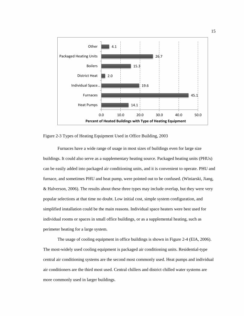
Figure 2-3 shows the usage of each heating equipment type in office buildings. Among
all the types of heating, furnaces are the most commonly used heating equipment, which is
followed by packaged heating units. Individual space heaters are the third most used but are
mainly used to supplement the building's main heating system. Boilers and district heat systems
are more often used in larger buildings (EIA, 2006).
15
Figure 2-3 Types of Heating Equipment Used in Office Building, 2003
Furnaces have a wide range of usage in most sizes of buildings even for large size
buildings. It could also serve as a supplementary heating source. Packaged heating units (PHUs)
can be easily added into packaged air conditioning units, and it is convenient to operate. PHU and
furnace, and sometimes PHU and heat pump, were pointed out to be confused. (Winiarski, Jiang,
& Halverson, 2006). The results about these three types may include overlap, but they were very
popular selections at that time no doubt. Low initial cost, simple system configuration, and
simplified installation could be the main reasons. Individual space heaters were best used for
individual rooms or spaces in small office buildings, or as a supplemental heating, such as
perimeter heating for a large system.
The usage of cooling equipment in office buildings is shown in Figure 2-4 (EIA, 2006).
The most-widely used cooling equipment is packaged air conditioning units. Residential-type
central air conditioning systems are the second most commonly used. Heat pumps and individual
air conditioners are the third most used. Central chillers and district chilled water systems are
more commonly used in larger buildings.
14.1
45.1
19.6
2.0
15.3
26.7
4.1
0.0 10.0 20.0 30.0 40.0 50.0
Heat Pumps
Furnaces
Individual Space…
District Heat
Boilers
Packaged Heating Units
Other
Percent of Heated Buildings with Type of Heating Equipment

16
Figure 2-4 Types of Cooling Equipment Used in Office Buildings, 2003
Similar to furnace, packaged air conditioning units were suited for a wide capacity range.
Also, they were easy to install, operate and maintain, and free of much equipment space.
Residential type central air conditioner means split-system air-cooled condensing unit with indoor
cooling coil and furnace. This system configuration is the most widely used unitary cooling
system for small to medium office buildings (ASHRAE, 2008). Individual air conditioners are
typically for small size office buildings due to low initial cost, quick installation, and flexible
control, such as occupied and unoccupied control. Figure 2-5 shows the number of different size
office buildings which followed an approach of using 5,000 and 50,000 square feet to categorize
building sizes. The percentage of large size office buildings is 4.25% (shown in Figure 2-5).
Comparing with CBECS 2003 results, the percentage of cooled buildings with a chiller is 3.7%
(shown in Figure 2-4); the percentage of heated buildings with a boiler is 15.3% (shown in Figure
2-3). It is more likely that at that time chillers were only used in large size office buildings, but
1.9
Q
42.9
3.7
1.1
13.5
13.5
34.6
0 10 20 30 40 50
Other
Swamp Coolers
Packaged Air Conditioning Units
Central Chillers
District Chilled Water
Individual Air Conditioners
Heat Pumps
Residential Type Central
Percent of Cooled Buildings with Type of Cooling Equipment

17
boilers were popular for both large size and medium size office buildings. However, the results
about HVAC systems in this report are merely about heating and cooling equipment. The
ventilation information (whether it is a VAV system or not) is not covered (Winiarski, Jiang, &
Halverson, 2006).
Figure 2-5 Percentage of Number of Different Size Office Buildings
2.2.2 Reference Office Building Models
Reference building models of the national building stock are created by the U.S.
Department of Energy (DOE) to develop standard or reference energy models for the most
common commercial buildings (DOE 2011). Reference HVAC equipment types for three types of
office buildings are given as one of the building energy model inputs. Winiarski et al. (2006)
from PNNL analyzed 2003 CBECS data and provided two sets of PNNL’s recommendation for
HVAC systems and equipment. These sets are (1) post-1980 buildings and (2) pre-1980
buildings, which are shown in Table 2-4.
Table 2-4 Reference HVAC systems from PNNL
Office
Type
Post-1980 Pre-1980
Heating Cooling Air Heating Cooling Air
(503 thousand)
61.12%
(285 thousand)
34.63%
(35 thousand)
4.25%
Small (1,001 to 5,000 sq ft)
Medium (5,001 to 50,000 sq ft)
Large (Over 50,000 sq ft)
18
Distribution Distribution
Large
Office Boiler Chiller MZ VAV Boiler Chiller MZ VAV
Medium
Office Furnace PACU MZ VAV Furnace PACU SZ CAV
Small
Office Furnace PACU SZ CAV Furnace PACU SZ CAV
Note: PACU – packaged air conditioning unit MZ – multi-zone SZ – single zone VAV – variable air volume
CAV – constant air volume
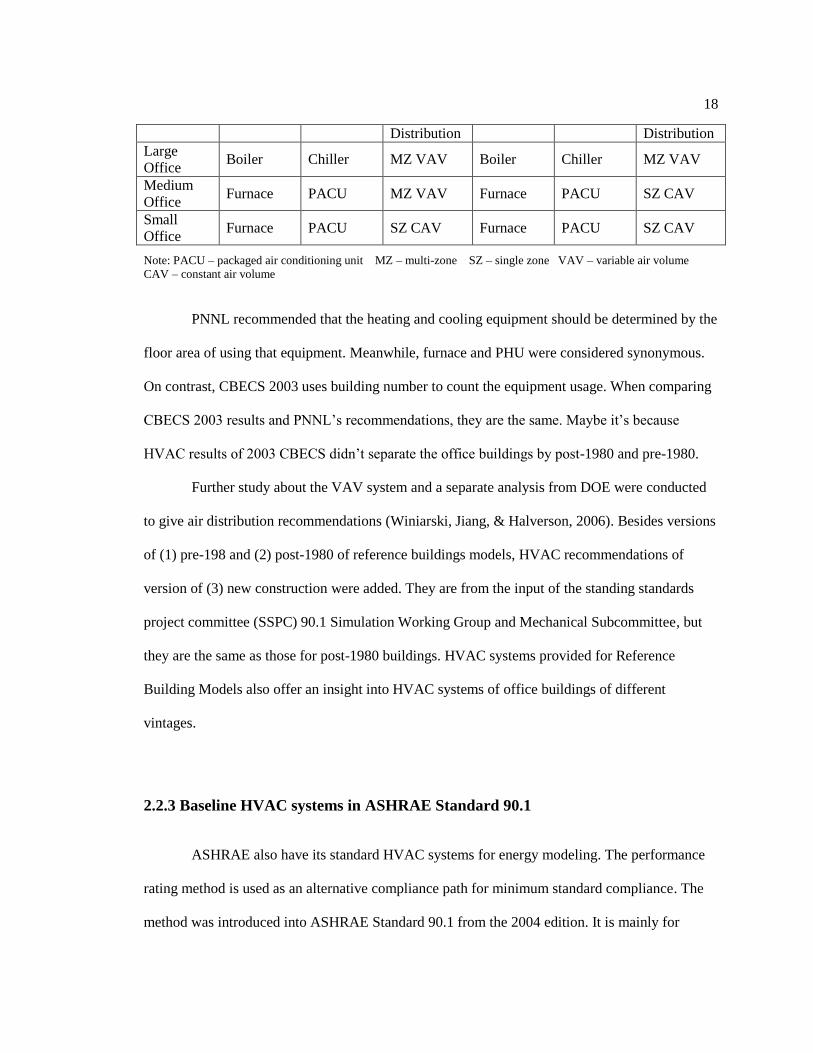
PNNL recommended that the heating and cooling equipment should be determined by the
floor area of using that equipment. Meanwhile, furnace and PHU were considered synonymous.
On contrast, CBECS 2003 uses building number to count the equipment usage. When comparing
CBECS 2003 results and PNNL’s recommendations, they are the same. Maybe it’s because
HVAC results of 2003 CBECS didn’t separate the office buildings by post-1980 and pre-1980.
Further study about the VAV system and a separate analysis from DOE were conducted
to give air distribution recommendations (Winiarski, Jiang, & Halverson, 2006). Besides versions
of (1) pre-198 and (2) post-1980 of reference buildings models, HVAC recommendations of
version of (3) new construction were added. They are from the input of the standing standards
project committee (SSPC) 90.1 Simulation Working Group and Mechanical Subcommittee, but
they are the same as those for post-1980 buildings. HVAC systems provided for Reference
Building Models also offer an insight into HVAC systems of office buildings of different
vintages.
2.2.3 Baseline HVAC systems in ASHRAE Standard 90.1
ASHRAE also have its standard HVAC systems for energy modeling. The performance
rating method is used as an alternative compliance path for minimum standard compliance. The
method was introduced into ASHRAE Standard 90.1 from the 2004 edition. It is mainly for
19
quantifying performance that substantially exceeds the requirements of Standard 90.1. Also it is
for evaluating the performance of all proposed designs, including alterations and additions to
existing buildings. This is useful in the simulation evaluation of retrofit work or high building
performance design. The baseline and the proposed building designs are compared in this
performance rating method to evaluate the improved performance of the proposed designs.
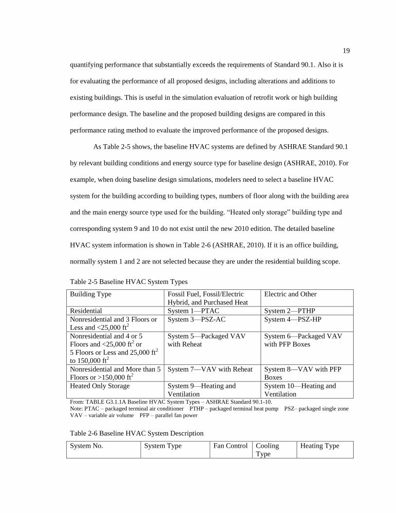
As Table 2-5 shows, the baseline HVAC systems are defined by ASHRAE Standard 90.1
by relevant building conditions and energy source type for baseline design (ASHRAE, 2010). For
example, when doing baseline design simulations, modelers need to select a baseline HVAC
system for the building according to building types, numbers of floor along with the building area
and the main energy source type used for the building. “Heated only storage” building type and
corresponding system 9 and 10 do not exist until the new 2010 edition. The detailed baseline
HVAC system information is shown in Table 2-6 (ASHRAE, 2010). If it is an office building,
normally system 1 and 2 are not selected because they are under the residential building scope.
Table 2-5 Baseline HVAC System Types
Building Type Fossil Fuel, Fossil/Electric
Hybrid, and Purchased Heat
Electric and Other
Residential System 1—PTAC System 2—PTHP
Nonresidential and 3 Floors or
Less and <25,000 ft2
System 3—PSZ-AC System 4—PSZ-HP
Nonresidential and 4 or 5
Floors and <25,000 ft2 or
5 Floors or Less and 25,000 ft2
to 150,000 ft2
System 5—Packaged VAV
with Reheat
System 6—Packaged VAV
with PFP Boxes
Nonresidential and More than 5
Floors or >150,000 ft2
System 7—VAV with Reheat System 8—VAV with PFP
Boxes
Heated Only Storage System 9—Heating and
Ventilation
System 10—Heating and
Ventilation From: TABLE G3.1.1A Baseline HVAC System Types – ASHRAE Standard 90.1-10.
Note: PTAC – packaged terminal air conditioner PTHP – packaged terminal heat pump PSZ– packaged single zone
VAV – variable air volume PFP – parallel fan power
Table 2-6 Baseline HVAC System Description
System No. System Type Fan Control Cooling
Type
Heating Type

20
1. PTAC Packaged terminal air
conditioner
Constant
volume
Direct
expansion
Hot-water fossil
fuel boiler
2. PTHP Packaged terminal
heat pump
Constant
volume
Direct
expansion
Electric heat
pump
3. PSZ-AC Packaged rooftop air
conditioner
Constant
volume
Direct
expansion
Fossil fuel
furnace
4. PSZ-HP Packaged rooftop
heat pump
Constant
volume
Direct
expansion
Electric heat
pump
5. Packaged VAV
with Reheat
Packaged rooftop
VAV with reheat
VAV Direct
expansion
Hot-water fossil
fuel boiler
6. Packaged VAV
with PFP Boxes
Packaged rooftop
VAV with parallel
fan power boxes and
reheat
VAV Direct
expansion
Electric
resistance
7. VAV with Reheat VAV with reheat VAV Chilled
water
Hot-water fossil
fuel boiler
8. VAV with PFP
Boxes
VAV with parallel
fan-powered boxes
and reheat
VAV Chilled
water
Electric
resistance
9. Heating and
Ventilation
Warm air furnace,
gas fired
Constant
volume
None Fossil fuel
furnace
10. Heating and
Ventilation
Warm air furnace,
electric
Constant
volume
None Electric
resistance From: TABLE G3.1.1B Baseline System Descriptions – ASHRAE Standard 90.1-10.
These baseline HVAC systems provides basic options for designers to be compared with
other HVAC systems in deciding whether the alternatives could be used in the project. This
energy modeling could be used for voluntary labeling such as LEED or utility incentive programs
with the goal to produce a building design that outperforms the code minimum or standard
practice (Higgins, 2012).
2.2.4 Advanced Energy Design Guides
Although ASHRAE Standard 90.1 is broken into envelope, lighting and HVAC systems,
the idea is to use an integrated approach to building design (Wallace, 2012). Also, focusing on
integrated design, the 50% Advanced Energy Design Guides (AEDGs) are a series of publications
designed to provide recommendations for achieving energy savings over the minimum code
21
requirements of ASHRAE Standard 90.1(ASHRAE 2004a). The design guidance and efficiency
recommendations are provided for small to medium office buildings up to 100,000 ft2. HVAC
systems, as part of their recommendations, are given according to climate zone. Each of
following HVAC systems has demonstrated the ability to meet the 50% savings criteria through
extensive computer simulations of a 20,000-ft2 small office and a 50,000-ft
2 medium office.
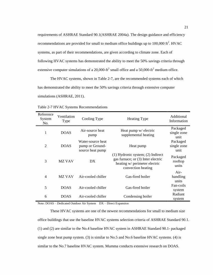
The HVAC systems, shown in Table 2-7, are the recommended systems each of which
has demonstrated the ability to meet the 50% savings criteria through extensive computer
simulations (ASHRAE, 2011).
Table 2-7 HVAC Systems Recommendations
Reference
System
No.
Ventilation
Type Cooling Type Heating Type
Additional
Information
1 DOAS Air-source heat
pump
Heat pump w/ electric
supplemental heating
Packaged
single zone
unit
2 DOAS
Water-source heat
pump or Ground-
source heat pump
Heat pump
Packaged
single zone
unit
3 MZ VAV DX
(1) Hydronic system; (2) Indirect
gas furnace; or (3) Inter electric
heating w/ perimeter electric
convection heating
Packaged
rooftop
units
4 MZ VAV Air-cooled chiller Gas-fired boiler
Air-
handling
units
5 DOAS Air-cooled chiller Gas-fired boiler Fan-coils
system
6 DOAS Air-cooled chiller Condensing boiler Radiant
system
Note: DOAS – Dedicated Outdoor Air System DX – Direct Expansion
These HVAC systems are one of the newest recommendations for small to medium size
office buildings that use the baseline HVAC systems selection criteria of ASHRAE Standard 90.1.
(1) and (2) are similar to the No.4 baseline HVAC system in ASHRAE Standard 90.1- packaged
single zone heat pump system. (3) is similar to No.5 and No.6 baseline HVAC systems. (4) is
similar to the No.7 baseline HVAC system. Mumma conducts extensive research on DOAS.

22
Radiant ceiling cooling panels were the best parallel system choice for use with the DOAS
(Stanley A. Mumma, 2001). These recommended systems are helpful to make comparisons with
the typical HVAC systems. Detailed recommendations for HVAC systems in each climate zone
are also given in this design guide.
2.3 HVAC System Influence on Building Energy Consumption
Literature directly related to HVAC system influence on building energy consumption is
limited. Performance and energy use of HVAC systems can be important factors to this topic and
some research have focused on it. The factors that influence the performance of an HVAC system
have been investigated, including characteristics of the building; ambient conditions and internal
design requirements; system type; efficiency of the primary system; and the air distribution
system, control strategy, and individual components (Zhang, Wright, & Hanby, 2006). Major
criteria are identified as having significant impact on the performance of HVAC configurations:
(1) the ability to minimize outside air load by minimizing both outside air mass flow rate and the
enthalpy difference between the outside air and the exhaust air, (2) the ability to eliminate
simultaneous cooling and heating, (3) the ability to use free cooling and (4) the availability of
inter-zonal air circulation paths. Systems that satisfy these criteria would be able to deliver the
desired indoor air quality with reduced energy consumption (Zhang, Wright, & Hanby, 2006;
Korolija, Marjanovic-Halburd, Zhang, & Hanby, 2011).
HVAC system or equipment efficiency and HVAC control requirements are two
important aspects which could have impact on the building energy consumption. A review of
HVAC systems energy requirements of building energy regulations was conducted. HVAC
equipment efficiency and HVAC control were two important categories in HVAC prescriptive
requirements (Pérez-Lombard, Ortiz, Coronela, & Maestre, 2011). This review defines four levels

23
of While HVAC control is not the main point in this thesis since its influence is not easy to reflect
in simulation program, that is what the simulation assumes that the HVAC systems are properly
installed, used and maintained. Air conditioning accounts for a major proportion of the energy
consumption of a building or facility, especially in hot and humid climates. Novel devices of
cooling system with high energy efficiency, innovative cooling system designs and intelligent
control strategies were described in the review, which can reduce energy use for air conditioning
(Chua, Chou, Yang, & Yan, 2013).
Building energy simulations are more and more used as a research tool to study and
compare building energy consumption due to using a variety of HVAC systems, which compares
HVAC system selections and performance. 36 HVAC and refrigerating systems are simulated in
a prototypical office building in the U.K. with four criteria – energy consumption, CO2 emission,
thermal comfort and indoor air quality to consider. VAV system when compared with CAV
system can reduce auxiliary energy consumption but uses slightly higher energy when used to
meet heating and cooling demands. Heat recovery units and economizers can reduce heating and
cooling consumption respectively. Thermal comfort and indoor air quality are often acceptable
while building energy use and CO2 output vary with system. Within the studied systems, CCHP
system with VAV and reheat consumes the highest energy, while the VAV system and heat
recovery emits the least CO2. The VAV system with reciprocating chiller and a gas boiler as well
as heat recovery unit consumes the least energy, respectively. This system, if using the absorption
chiller, can have the lowest CO2 emission (Shahrestani, Yao, & Cook, 2013). With similar
methodology, building energy simulations of eighteen HVAC system types in seven commercial
building types (including small office building) were conducted. Conclusions have been found
that usually humidity control is not an issue for office buildings. Demand controlled ventilation
(DCV) saves energy because it can reduce the ventilation flow rate. Both DCV and enthalpy can
reduce life-cycle cost (Witte & Henninger, 2006). Similar comparative studies of energy
24
performance of different HVAC systems for office buildings have been done and an optimal
HVAC system can always be selected because of some certain criteria, such as energy
consumption. However, the drawback of this approach is the results are applicable to the
particular building and climate, which is difficult to apply the findings to other circumstances
(Zhang, Wright, & Hanby, 2006). If it is just for one specific location or climate zone, then
energy simulations of several HVAC systems can be run for one particular building or one
building type to make comparisons and see if HVAC systems can have impact on the building
energy consumption with climate influence excluded (Liu & Hong, 2010; Bojic, Nikolic, Nikolic,
Skerlic, & Miletic, 2011; Korolija, Marjanovic-Halburd, Zhang, & Hanby, 2011).
2.4 Conclusions of Literature Review
This chapter reviewed (1) HVAC selection, (2) existing recommendations to select
HVAC systems, and (3) influence of the HVAC system selection on the energy consumption of
buildings to identify knowledge gaps in the existing publications. Review of common selections
of HVAC systems for office buildings is helpful to have a whole idea of HVAC system types and
categories for office buildings. This also helps to understand characteristics and design
considerations of these systems.
Review of previous research on the selection of HVAC systems shows that (1) DOE
Reference Building Models, (2) ASHRAE Standard 90.1, and (3) Advanced Energy Design
Guide are common references for small to medium office buildings. These systems can be used to
compare with the typical HVAC systems extracted from 134 LEED NC certified office buildings.
Additionally, this study uses basic system information, similar to the system description approach
of ASHRAE Standard 90.1, to establish a general category for classification of proposed HVAC
systems. HVAC systems of Reference Buildings Models are real system designs; these systems

25
were built at least 10 years ago or even earlier. The proposed HVAC systems of LEED certified
office buildings are within a recent vintage. The reviewed results of typical proposed HVAC
systems of these newly constructed office buildings might provide different system selections.
The review of existing literature on the direct influence of HVAC systems on the building
energy consumption shows that there are limited studies. Much research regarding energy
simulation of different HVAC systems for buildings can be found, but few studies focus on the
relationship between different HVAC systems and total energy consumption of office buildings.
This is the main target of this study.

Chapter 3
Frequently-used HVAC System Types for High Performance Office Buildings
Frequently-used HVAC system types for high performance office buildings are identified
from 134 LEED certified office buildings. In LEED projects, baseline designs comply with
energy standard requirements; proposed designs are used to compare with baseline ones to see
energy savings. Baseline and proposed HVAC systems are provided in these two designs. The
proposed primary HVAC system type is the main focus in this thesis. The frequently-used
proposed HVAC system types are defined by system preferences in these 134 certified office
buildings.
3.1 HVAC System Types for LEED Certifications
In LEED projects, baseline designs comply with energy standard requirements; proposed
designs are used to compare with baseline ones to see energy savings. The baseline HVAC
systems are based on the ASHRAE Standard 90.1 2004/2007 Appendix G and California Title
24-2005. The proposed HVAC systems should reflect the actual designs. In the LEED submitted
documents, primary HVAC system type, other HVAC system type provide a brief description of
the HVAC systems for the baseline design and the proposed design, which are the main sources
to extract fan control, cooling and heating types of HVAC system information (U.S. Green
Building Council, 2014). Other HVAC _related information, such as unitary heating, cooling
capacity, efficiency, and technique specifications of boiler, chiller, and cooling tower are also
helpful to identify the heating and cooling types. Fan system operation is important to specify
whether the system uses a CAV or VAV system. Some projects may use more than one primary

27
HVAC Type, the main primary HVAC Type is determined by the larger system capacity, amount
of equipment, fan power, or airflow rate of the system. This thesis defines the HVAC system type
by information of ventilation, cooling and heating types.
3.2 Baseline HVAC Systems
The previous section of 2.2.3 already reviews the baseline HVAC system types in
ASHRAE Standard 90.1-2010. Figure 3-1 shows how baseline HVAC systems are selected for
office buildings. DOE Reference Building Models categories buildings sizes into: (1) small, (2)
medium, and (3) large buildings. Small, medium, and large buildings have areas less than
5,000ft2, between 5,001ft
2 to 50,000ft
2, and more than 50,001ft
2, respectively.
Small size office buildings typically select baseline No.3 and No.4 HVAC systems, large
size office buildings typically select baseline No.5, No. 6 and No.7 HVAC systems. The No.8
system is not that popular because it is for a quite large office building and it is not that common
to use electricity as the main heating fuel source. Middle size office buildings are the major type
(shown in Table 3-1), and they can select from No.3 and No.4 systems, or from No.5 and No.6
systems. That’s why No.3, No.4 and No.5 are much more selected than the other baseline HVAC
systems. These three baseline HVAC systems are:
• No.3 - Packaged CAV with DX_AC cooling and furnace heating
• No.4 - Packaged CAV system with Heat Pump DX cooling and heating
• No.5 - Packaged VAV reheat system with DX cooling and Boiler heating
The No.5 and the No.6 baseline HVAC systems are selected based on the same building
conditions, but the No.6 system is not as popular as the No.5 system. A small number of No.7
baseline systems (VAV with chiller and hot water reheat) are selected in this LEED office
building sample because there are not many extremely large office buildings, and the No.5 system

28
is more popular in normally large office buildings. These five types of baseline HVAC systems
(1) provide system selections in the first development phase of automated energy simulation
tools, and (2) satisfy HVAC system type requirement for standard compliance.
Figure 3-1 Map of Baseline HVAC System Selection for Office Buildings
Figure 3-2 Number of Each Baseline HVAC System
35
45
35
12
5
1
0
5
10
15
20
25
30
35
40
45
50
No. 3 No. 4 No. 5 No. 6 No. 7 No. 8
Qu
an
tity
Baseline HVAC Systems

29
Table 3-1 Building Size Distribution
Building Size Number of Buildings Percentage of Buildings
Small 10 7.46%
Medium 94 70.15%
Large 30 22.39%
3.3 Proposed HVAC Systems
During the process of identifying proposed HVAC systems, the diverse descriptions of
HVAC systems shows a need to categories the fan control, cooling and heating types (shown in
Table 3-2). Usually, most of proposed HVAC system designs have more than one system type,
but only the primary HVAC system type is selected to represent the whole building system type.
For example, a building uses VAV DX cooling and boiler heating for the major building part, and
at the same time it might use CAV DX cooling for its data center. Herein, the proposed HVAC
system type means the primary system in these LEED office buildings.
Table 3-2 General HVAC System Category to Identify Proposed HVAC Systems
Fan
Control
Type
Cooling Type Heating Type
DX_AC DX_HP Chiller Boiler Furnace +
PHU
Electricity HP
CAV Air conditioning
unit
Air source HP Air-
cooled
Boiler Furnace and
Packaged
heating unit
Electricity Air
source
VAV AHU w/
condensing unit
Water source
HP
Water-
cooled
Water
source
Variable volume
temperature
(VVT)
Ground source
HP
Ground
source HP
Variable
refrigerant flow
(VRF)
VRF
The identified proposed HVAC systems are presented in Table 3-3. The proposed HVAC
system index makes it easy to mention each system later in this study. P_EB3 through P_EB7 are

30
defined as frequently-used proposed HVAC systems because the number of these systems are all
larger than 10, and they cover 74% of all identified HVAC systems. The LEED certified forms of
16 buildings do not provide clear fan control types, which prohibit this group of systems having
completed system configuration information to compare with other proposed systems.
Table 3-3 Identified Proposed HVAC Systems
Proposed
System
Index
Proposed System Full Name HVAC system Type System
Quantity
P_EB3 Proposed packaged CAV DX air
conditioner cooling and furnace or
furnace heating, which is equivalent to
Baseline No. 3 system
CAV + DX_AC +
Furnace
11
P_EB4 Proposed CAV heat pump cooling and
heating with other supplemental heating,
which is equivalent to Baseline No. 4
system
CAV + DX_HP + HP* 23
P_EB5 Proposed packaged VAV DX air
conditioner cooling and boiler heating,
which is equivalent to Baseline No. 5
system
VAV + DX_AC + Boiler 15
P_EB6 Proposed packaged VAV DX air
conditioner cooling and electric heating,
which is equivalent to Baseline No. 6
system
VAV + DX_AC + Elec 10
P_EB7 Proposed VAV chiller cooling and boiler
heating, which is equivalent to Baseline
No. 7 system
VAV + Chiller + Boiler 26
P_EB8 Proposed VAV chiller cooling and
electric heating, which is equivalent to
Baseline No. 8 system
VAV + Chiller + Elec 4
P_9 Proposed No.9 dedicated outdoor air
system with DX heat pump cooling and
heating and other supplemental heating
DOAS + DX_HP + HP 9
P_10 Proposed No.10 VAV with DX air
conditioner cooling and furnace heating
VAV + DX_AC +
Furnace
6

31
P_11 Proposed No.11 VAV with DX air
conditioner cooling and furnace heating
VAV + DX_HP + HP 5
P_12 Proposed No.12 CAV with chiller
cooling and boiler heating
CAV + Chiller + Boiler 3
P_13 Proposed No.13 VAV with DX air
conditioner cooling and electric heating
CAV + DX_AC + Elec 2
P_14 Proposed No.14 CAV with DX air
conditioner cooling and boiler heating
CAV + DX_AC + Boiler 2
P_15 Proposed No.15 VAV with purchased
chilled water cooling and electric heating
VAV + Purchased CHW
+ Elec
1
P_16 Proposed No.16 demand ventilation plus
underfloor air distribution and chill beam
system with chiller cooling and boiler
heating
DV/UFAD/Chillbeam +
Chiller + Boiler
1
Ventilation Not Provided 16
P_171 Proposed No.17-1 heat pump systems (HP Systems) 11
P_172 Proposed No.17-2 DX air conditioner
cooling and boiler heating
(DX_AC + Boiler) 4
P_173 Proposed No.17-3 DX air conditioner
cooling and furnace heating
(DX_AC + Furnace) 1
Note:
1. HP* means the heating type is heat pump only or heat pump with other supplemental heating.
2. “Equivalent” here does not mean totally equal. It gives the sense to capture similar baseline system
type.
3.4 HVAC System Type Comparisons between 2003 CBECS and LEED Certified
Office Buildings
The HVAC systems of 2003 Commercial Building Energy Consumption Survey
(CBECS) and a sample of LEED certified office buildings project different comparisons: (1)
2003 CBECS vs. LEED baseline compares the HVAC system types in existing office building
stock with recommendations for energy code compliance. (2) Both 2003 and LEED proposed

32
systems are all real system applications. But LEED proposed systems represent the most recent
system practices and has proven their advantages beyond energy standard requirement.
2003 Commercial Building Energy Consumption Survey (CBECS) provides HVAC
systems of office buildings from as early from the 1840s to 2003, which is helpful to understand
the traditional HVAC systems of office buildings in different periods. 2003 CBECS defines
building sizes as small, medium and large by building areas up to 5,000 ft2, between 5,001 to
50,000 ft2, and over 50,000 ft
2, respectively. By examining the main heating, cooling and air
conditioning types of office buildings in 2003 CBECS data, the top two percentages of heating
cooling types and ventilation types for each office building size in three time periods (1) pre-
1960, (2) between 1960 to 1989, and (3) post-1990 are shown in Figure 3-3 (a) (b) and (c). The
percentages are based on numbers of buildings using the main heating and cooling equipment.
From 2003 CBECS data, boilers and furnaces have been the main heating types for large
and small office buildings, respectively. For medium office buildings, furnace and PHU are the
most common options since 1960. These two heating types are considered to have a large overlap
due to CBECS limitations in terminology (Winiarski, Jiang, & Halverson, 2006). Based on
typical baseline HVAC systems, boilers are still the primary heating type for large office
buildings. No.3 and No.4 systems are typically selected for small and medium office buildings.
Thus, furnace and electric heat pump are the main baseline heating types for both small and
medium LEED NC office buildings.
After 1990, heat pump systems began to be widely applied in small office buildings. It
was also recommended as a baseline HVAC system in ASHRAE Standard 90.1 to utilize the high
coefficient of performance for all small and part of medium office buildings. But the application
and characteristics of heat pump systems, especially in some specific climate regions, need
further investigations.

33
Chillers were the main cooling type for pre-1990 large office buildings. After 1990
packaged air conditioning units (PACU) became more common in large office buildings. PACU
was the dominant cooling type for all vintages of medium office buildings. Before 1990,
residential-type central air conditioning systems were very common in small office buildings.
After 1990, PACU and heat pump systems became more common. In LEED office buildings,
No.5 baseline HVAC systems are typically used for large office buildings and no chiller is
included in typical baseline HVAC systems. That’s why DX air conditioning units are so much
more selected in large office buildings. Similarly, DX heat pump and air conditioning systems are
the main baseline cooling types for medium and small office buildings.
VAV was slightly more used in pre-1960 large office buildings. After that, VAV gained
even more applications than CAV in large office buildings. Both LEED baseline and proposed
HVAC systems show a great difference in these two ventilation types. Medium office buildings
had a clear preference for CAV systems in all vintages. Even LEED baseline systems of medium
office buildings present a similar pattern. But in contrast, VAV systems are a bit more common in
LEED proposed systems of medium office buildings. For small size office buildings, CAV
always has significantly more usage than VAV.

34
0
20
40
60
80
100
L-B
oil
erL
-DH
M-B
oil
erM
-Fu
rnac
eS
-Fu
rnac
eS
-Boil
er
L-B
oil
erL
-PH
UM
-PH
UM
-Fu
rnac
eS
-Fu
rnac
eS
-PH
U
L-B
oil
erL
-PH
UM
-Fu
rnac
eM
-PH
US
-Fu
rnac
eS
-HP
L-B
oil
erL
-Ele
c H
PM
-Ele
c H
PM
-Fu
rnac
eS
-Fu
rnac
eS
-Ele
c H
P
L-B
oil
erL
-Ele
cM
-HP
*M
-Boil
erS
-HP
*S
-Boil
er
Pre-1960 2003
CBECS
1960-1989 2003
CBECS
Post-1990 2003
CBECS
LEED NC
Baseline
LEED NC
Proposed
3-3 (a)
Note: L, M, and S – Large, Medium and Small Size DH – district steam and hot water
PHU – packaged heating unit Elec HP – electric heat pump
0
20
40
60
80
100
L-C
hil
ler
L-P
AC
UM
-PA
CU
M-R
TC
AC
S-R
TC
AC
S-I
R A
C
L-C
hil
ler
L-P
AC
UM
-PA
CU
M-R
TC
AC
S-R
TC
AC
S-P
AC
U
L-P
AC
UL
-Chil
ler
M-P
AC
UM
-RT
C A
CS
-PA
CU
S-H
P
L-D
X A
CL
-DX
HP
M-D
X H
PM
-DX
AC
S-D
X A
CS
-DX
HP
L-C
hil
ler
L-D
X A
CM
-DX
HP
M-D
X A
CS
-DX
AC
S-D
X H
P
Pre-1960 2003
CBECS
1960-1989 2003
CBECS
Post-1990 2003
CBECS
LEED NC
Baseline
LEED NC
Proposed
3-3 (b)
Note: L, M, and S – Large, Medium and Small Size PACU – packaged air conditioning unit
RTC AC – residential-type central air conditioning DX – direct expansion

35
Figure 3-3 Percentage of two most common (a) heating systems, (b) cooling systems, and (c) air
distribution systems by building size and vintage
HVAC system type comparisons between 2003 CBECS and LEED office buildings are
based on their applications in different building sizes, which present the general application trend
differences. However, where the value of LEED buildings lies is the energy consumption merits.
The HVAC energy consumption difference between LEED and existing office buildings due to
HVAC system types still needs further investigation.
0
20
40
60
80
100
L-V
AV
L-C
AV
M-V
AV
M-C
AV
S-V
AV
S-C
AV
L-V
AV
L-C
AV
M-V
AV
M-C
AV
S-V
AV
S-C
AV
L-V
AV
L-C
AV
M-V
AV
M-C
AV
S-V
AV
S-C
AV
L-V
AV
L-C
AV
M-V
AV
M-C
AV
S-V
AV
S-C
AV
L-V
AV
L-C
AV
M-V
AV
M-C
AV
S-V
AV
S-C
AV
Pre-1960 2003
CBECS
1960-1989 2003
CBECS
Post-1990 2003
CBECS
LEED NC
Baseline
LEED NC
Proposed
3-3 (c)
Note: L, M, and S – Large, Medium and Small Size VAV – variable air volumn
CAV – constant air volumn

Chapter 4
Energy Consumption Characteristics
With frequently-used proposed primary HVAC system types from those 134 LEED
certified office buildings established, the next step is to explore their energy consumption
characteristics, regarding heating, cooling, and fan and pump energy consumption. Some of these
certified office buildings have extremely high total energy use intensity due to high process
related energy uses in mixed space such as data center, laboratory, or industrial manufacturing,
which means they are not typical office buildings. These buildings need to be excluded as
outliers.
4.1 Outlier Exclusion
Some certified office buildings have extremely high total energy use intensity (EUI,
calculated by total energy use over gross footage area) due to intensive heating, cooling, or high
process related energy uses in mixed spaces with office area such as data center, laboratory, or
industrial manufacturing, which means these buildings are not typical office buildings. They are
identified as outliers and excluded from the energy consumption analyses.
Outliers are identified by having a total EUI below a lower limit, Q1-1.5×IQR, or over an
upper limit, Q3+1.5×IQR. IQR, Q1, and Q3 are the interquartile range and the medians of the
lower and upper half of the proposed total EUI (Heidarinejad & Dahlhausen, 2013). 11 buildings
are excluded based on this outlier omission approach. Table 4-1 presents outlier quantities within
each identified proposed HVAC systems.
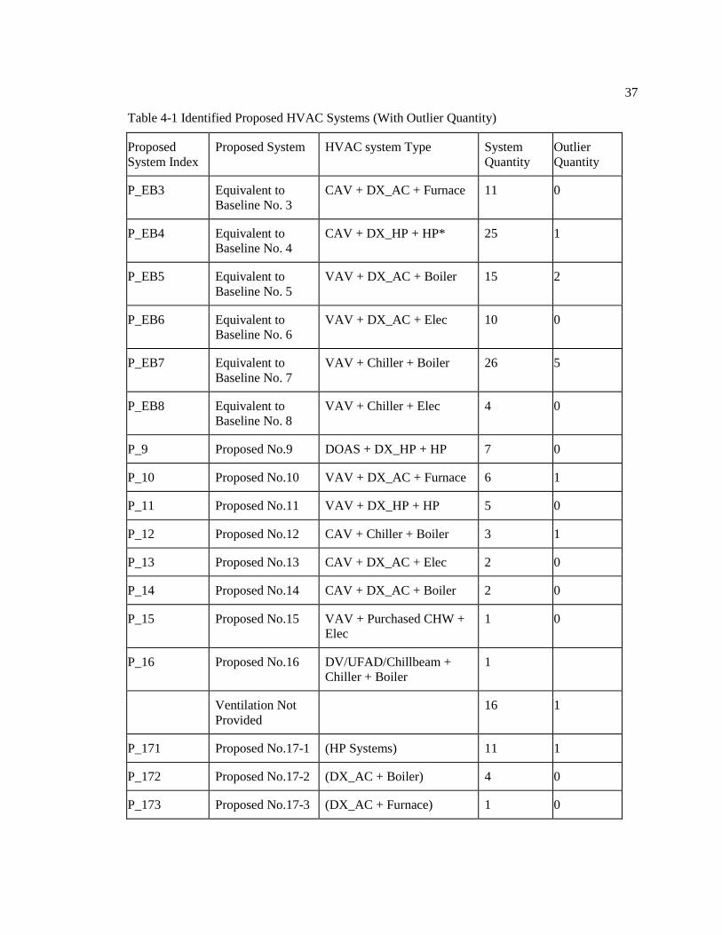
37
Table 4-1 Identified Proposed HVAC Systems (With Outlier Quantity)
Proposed
System Index
Proposed System HVAC system Type System
Quantity
Outlier
Quantity
P_EB3 Equivalent to
Baseline No. 3
CAV + DX_AC + Furnace 11 0
P_EB4 Equivalent to
Baseline No. 4
CAV + DX_HP + HP* 25 1
P_EB5 Equivalent to
Baseline No. 5
VAV + DX_AC + Boiler 15 2
P_EB6 Equivalent to
Baseline No. 6
VAV + DX_AC + Elec 10 0
P_EB7 Equivalent to
Baseline No. 7
VAV + Chiller + Boiler 26 5
P_EB8 Equivalent to
Baseline No. 8
VAV + Chiller + Elec 4 0
P_9 Proposed No.9 DOAS + DX_HP + HP 7 0
P_10 Proposed No.10 VAV + DX_AC + Furnace 6 1
P_11 Proposed No.11 VAV + DX_HP + HP 5 0
P_12 Proposed No.12 CAV + Chiller + Boiler 3 1
P_13 Proposed No.13 CAV + DX_AC + Elec 2 0
P_14 Proposed No.14 CAV + DX_AC + Boiler 2 0
P_15 Proposed No.15 VAV + Purchased CHW +
Elec
1 0
P_16 Proposed No.16 DV/UFAD/Chillbeam +
Chiller + Boiler
1
Ventilation Not
Provided
16 1
P_171 Proposed No.17-1 (HP Systems) 11 1
P_172 Proposed No.17-2 (DX_AC + Boiler) 4 0
P_173 Proposed No.17-3 (DX_AC + Furnace) 1 0

38
4.2 Energy Consumption Comparisons among Frequently-used Proposed Primary
HVAC System Types
Energy use intensities of heating, cooling, and fan with pump are compared to explore the
energy consumption characteristics among the five frequently-used proposed primary HVAC
system types (from P_EB3 through P_EB7). Figure 4-1 shows the heating, cooling, and fan with
pump, as well as HVAC, Non-HVAC, and total energy use intensity comparisons among the
frequently-used proposed primary HVAC system types. The bar shows the average EUI, and the
grey dash shows individual energy consumption of that HVAC system type.
The P_EB3 uses furnace. Both P_EB5 and P_EB7 use boilers as their heating types.
Normally furnace and boiler use gas for heating. They consume similar amount of energy for
heating. But their heating consumptions are much more than heat pump heating from P_EB4 and
electric heating from P_EB6. Part of reason comes from the climate regions of the buildings. In
colder area, more heat is needed. Figure 4-2 shows the heating degrees of the frequently-used
proposed primary HVAC system types. The heating demand of P_EB3, P_EB5 and P_EB7 are
quite similar, and P_EB6 systems locate more in the warm regions, which explains the heating
consumption comparisons between P_EB3, 5, 7 and P_EB6. The heat pump systems of P_EB4
can be found in all climate regions, which means the heat pump systems are gradually gaining
application even in cold climate regions. The heating consumptions are relatively low when
comparing with other frequently-used proposed primary HVAC systems due to a great advantage
in coefficient of performance. And also most of heat pump systems implement energy recovery
ventilation to maximize the heat recycling from the exhaust air.
The cooling consumptions do not vary significantly among the frequently-used proposed
HVAC systems. P_EB6 consume more energy for cooling due to higher cooling demand, which
is shown in Figure 4-3. In contrast, P_EB3 use less cooling because most of these buildings have

39
less cooling demand. Even heat pump systems of P_EB4 have larger cooling need than P_EB3, 5,
and 7 (shown in Figure 4-2), there are not significant differences in the cooling consumptions.
Figure 4-1 Site Energy Use Intensity Comparisons among Frequently-used Proposed Primary
HVAC System Types
0.0
10.0
20.0
30.0
40.0
50.0
60.0
70.0
80.0
90.0
0.0
10.0
20.0
30.0
40.0
50.0
60.0
70.0
80.0
90.0
Heating Cooling Fan&Pump HVAC Non-HVAC Total
EUI
(Btu
/sf)
P_EB3 P_EB4 P_EB5 P_EB6 P_EB7

40
Figure 4-2 Heating Degree Days of Frequently-used Proposed Primary HVAC System Types
Figure 4-3 Cooling Degree Days of Frequently-used Proposed Primary HVAC System Types
P_EB7P_EB6P_EB5P_EB4P_EB3
10000
8000
6000
4000
2000
0
Da
ta95% CI for the Mean
Heating Degree Days (HDD65)
P_EB7P_EB6P_EB5P_EB4P_EB3
12000
10000
8000
6000
4000
2000
0
Da
ta
95% CI for the Mean
Cooling Degree Days (CDD50)

41
Based on site energy use intensity, buildings using P_EB4 systems have the least average
HVAC EUI. Great differences in the heating EUI can have direct impact on the total EUI patterns
of buildings those use frequently-used proposed HVAC system types, if they have the same Non-
HVAC EUI.
In order to get rid of the impact from climate condition on the energy consumption,
weather normalized heating site EUI (heating site EUI divided by heating degree days) and
cooling site EUI (cooling source EUI divided by cooling degree days) are provided as Figure 4-4
and Figure 4-5 to compare the heating and cooling consumption among these frequently-used
proposed HVAC systems. P_EB4 has the least heating site energy use intensity and the least
weather normalized heating site EUI. The heating and cooling consumption patterns of these five
frequently-used proposed HVAC systems basically follow the same patterns of heating and
cooling site EUI. That means the climate conditions has minor effect on the heating and cooling
consumption of these five frequently-used proposed HVAC systems, which, from another way,
supports the conclusion that these LEED certified office buildings are internal load dominated
(Heidarinejad, Dahlhausen, & Srebric, 2013).

42
Figure 4-4 Weather Normalized Heating Site EUI of Frequently-used Proposed Primary HVAC
System Types
Figure 4-5 Weather Normalized Cooling Site EUI of Frequently-used Proposed Primary HVAC
System Types
76543
5
4
3
2
1
0
P_EB
We
ath
er
No
rma
lize
d E
UI
(Btu
/sq
ft/
de
gre
e d
ay
) 95% CI for the Mean
Weather Normalized Heating Site EUI
76543
6
5
4
3
2
1
0
P_EB
We
ath
er
No
rma
lize
d E
UI
(Btu
/sq
ft/
de
gre
e d
ay
) 95% CI for the Mean
Weather Normalized Cooling Site EUI

43
The variation of fan and pump EUI is not obvious as heating and cooling EUI among
these five HVAC systems. P_EB4 and P_EB7 have both fans and pumps in the system, which
could be the reason that these two systems consume a bit more energy for fans and pumps than
the other three HVAC systems.
When looking at the building areas of each frequently-used proposed HVAC system type,
different characteristics can be observed. Figure 4-6 shows the distribution of building gross
footage areas of the frequently-used proposed HVAC system types. Office buildings using
P_EB3 and P_EB4 systems have a similar building area range from about 5,000 ft2 to around
30,000 ft2. Both two systems are packaged single zone CAV system. Normally, for buildings of
this area range, multiple systems are needed. P_EB5 are more used in typical middle size building
with area range from 10,000 ft2 to 40,000 ft
2. Even P_EB5 is multi-zone VAV system, but a
number of systems are still needed if the building is of this size or larger. But a good advantage is
that these systems can share one boiler or two, depending on the redundancy and reliable
requirement or optimal design. A VAV system with DX cooling and electric reheat (Baseline
No.6) is recommended by ASHRAE Standard 90.1 for the same building conditions as they are
recommended with VAV with DX cooling and hot water reheat supplied by boiler (Baseline
No.5). However, in the proposed designs, buildings using P_EB6 systems have a larger variation
in the building area, from roughly 25,000 ft2 to 10,000 ft
2, which is quite different from those
using P_EB5. This is a typical example to indicate that the building size is not and cannot be the
only factor to select a proper HVAC system type. As discussed above, these P_EB6 systems have
less heating demand because most of them locate in the warm regions. A small amount of electric
heat shows better economic advantage when comparing with a boiler to supply hot water, which
needs high first cost and high operation cost. Typically, P_EB7 systems are more used in large
office buildings. But if there are large demands in heating and cooling in an office building less

44
than 50,000 ft2, a VAV with chiller and boiler is still a decent option because the building can
benefit from the high efficiency of the central plant.
Figure 4-6 Box Plot of Building Gross Footage Area for Frequently-used Proposed HVAC
System Types
When combined the comparisons of weather normalized heating and cooling site EUI and
building size characteristics of these five frequently-used HVAC systems, the application can be
summarized as Table 4-2. P_EB3 and 4 systems are almost all used for buildings which are under
25,000 ft2. P_EB4 can have wide application in most climate regions, and P_EB3 system can also
have better utilization in hot, mild and cold climate regions. Most P_EB5 systems are used for
buildings which are less than 50,000 ft2, and better for cold and mild climate regions to minimize
the heating consumption. Most of P_EB6 and 7 systems are used for buildings between 25,000 ft2
and 100,000ft2. P_EB6 systems have a great advantage in mild and hot climate regions with small
heating demand. It is not a first choice to use P_EB6 for a large office building in cold climate
P_EB7P_EB6P_EB5P_EB4P_EB3
200000
175000
150000
125000
100000
75000
50000
25000
0
GF
A (
sf)
Boxplot of GFA for P_EB3, P_EB4, P_EB5, P_EB6, P_EB7

45
region because it uses electricity for heating. But P_EB7 systems are well used for mild and cold
climate regions.
Table 4-2 Applications of Frequently-used HVAC System Types
P_EB3 P_EB4 P_EB5 P_EB6 P_EB7
Building Size
(ft2)
< 25,000 < 25,000 <50,000 Mostly
(25, 000 100,000),
or larger
Mostly
(25, 000 100,000),
or larger
Preferred
Climate Regions
Hot,
Mild,
Cold
Hot,
Mild,
Cold
Mild,
Cold
Hot, Mild Mild, Cold
4.3 Energy Consumption Characteristics Based on Clusters
As mentioned above, building size alone cannot be the only factor to select or evaluate
HVAC systems. Energy consumption characteristics also matters. Cluster analysis from a study
of the same 134 LEED NC certified office buildings comes up with three classes of office
buildings by energy use intensity, after excluding outlier buildings based on the total energy use
intensity. The median EUI for high, medium, and low energy intensity are 78.4, 48.2 and 31.0
kBtu/ft2, respectively. The median building size of high and medium clusters are similar to each
other, 25,000-30,000 ft2, which is about two times as large as those in low intensity cluster,
11,744 ft2 (Heidarinejad & Dahlhausen, 2013). Combining building characteristics and energy
consumption characteristics, these three clusters are of great importance to provide a further
grouping approach to compare the energy consumption characteristics of the frequently-used
proposed HVAC systems. Based on the cluster information, Table 4-3 presents the distribution of
frequently-used proposed HVAC systems in different clusters. It is more likely that P_EB3 and
P_EB4 distribute more in low and medium energy intensity office buildings. It is necessary to
compare the energy consumption between low cluster and medium cluster for P_EB3 and P_EB4
to see what results in the cluster difference. P_EB5 does not exist in low intensity cluster, and

46
P_EB6 does not exist in high intensity cluster. There is high possibility that P_EB7 exist in
medium and high intensity clusters, but it does not mean that VAV system with chiller and boiler
(P_EB7) cannot exist in low energy intensity clusters.
Table 4-3 Cluster Distribution of Frequently-used Proposed HVAC systems
Proposed
System Index
System Quantity
(Excluding Outliers)
Low Intensity
Cluster
Medium
Intensity Cluster
High Intensity
Cluster
P_EB3 11 5 5 1
P_EB4 24 12 11 1
P_EB5 13 0 9 4
P_EB6 10 3 7 0
P_EB7 21 2 15 4
Figure 4-7 presents the cluster comparisons of Non-HVAC for P_EB3 through P_EB7.
The Non-HVAC energy consumptions show a clear pattern among different clusters. Non-HVAC
use is the major contributor to result in cluster classification. But in terms of different frequently-
used proposed HVAC systems, the contribution of Non-HVAC EUI in cluster classification is
different. The average Non-HVAC EUI of P_EB3, 4, 6, and 7 in low intensity clusters is about 18
kBtu/ft2. The average Non-HVAC EUI of five systems in medium intensity clusters is close to 30
kBtu/ft2. There is a huge difference between Non-HVAC EUI in medium and high intensity
clusters for P_EB5, while this difference for P_EB7 is quite small. Conclusively, the cluster
comparisons of Non-HVAC use indicate the great contribution of Non-HVAC consumption in
making different intensity clusters for P_EB3, 4, 5, and 6. Still, the comparisons of HVAC use for
these four systems can help to show what differentiates the same system in different clusters
considering the impact from a clear pattern of Non-HVAC consumption. But for P_EB7, the great
contributor to high intensity cluster is from HVAC energy use.

47
Figure 4-7 Cluster Comparison of Non-HVAC Use for P_EB3-7
Figure 4-8 through Figure 4-12 show the cluster comparisons for P_EB3 through P_EB7,
respectively. For P_EB3, the heating in cluster 2 has great variation, because two of the buildings
need less heating but more cooling. The high cooling demands of the other three buildings is
because of the increase of Non-HVAC consumption and small cooling demand according to the
cooling degree day information. Fans in P_EB3 systems not only need to bring in fresh air due to
occupancy requirements, but also have to deal with the high cooling load from the increase of
Non HVAC EUI in the medium cluster.
P_EB
Cluster
76543
321321321321321
120
100
80
60
40
20
0
Pro
po
se
d_
No
n_
HV
AC
_EU
I95% CI for the Mean
Comparisons of Non-HVAC EUI
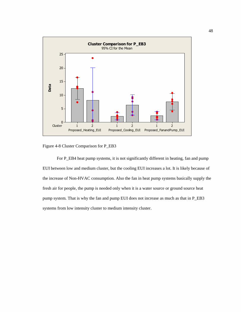
48
Figure 4-8 Cluster Comparison for P_EB3
For P_EB4 heat pump systems, it is not significantly different in heating, fan and pump
EUI between low and medium cluster, but the cooling EUI increases a lot. It is likely because of
the increase of Non-HVAC consumption. Also the fan in heat pump systems basically supply the
fresh air for people, the pump is needed only when it is a water source or ground source heat
pump system. That is why the fan and pump EUI does not increase as much as that in P_EB3
systems from low intensity cluster to medium intensity cluster.
Cluster
Proposed_FanandPump_EUIProposed_Cooling_EUIProposed_Heating_EUI
212121
25
20
15
10
5
0
Da
ta95% CI for the Mean
Cluster Comparison for P_EB3

49
Figure 4-9 Cluster Comparison for P_EB4
For P_EB5 VAV with DX_AC cooling and boiler system, the HVAC EUI increase from
medium to high cluster is not significant because the Non-HVAC EUI increases a lot.
Interestingly, the cooling EUI or fan and pump EUI does not increase as the Non-HVAC EUI
increases, maybe it is because the large process load in the building does not need to cool down,
or there is a dedicated DX system dealing with this part of the cooling load, for example, most of
these buildings have data centers, and separate DX systems are usually installed dedicatedly to
cool this space.
P_EB
Cluster
Proposed_FanandPump_EUIProposed_Cooling_EUIProposed_Heating_EUI
444
212121
14
12
10
8
6
4
2
0
Da
ta95% CI for the Mean
Cluster Comparisons of P_EB4

50
Figure 4-10 Cluster Comparison for P_EB5
For P_EB6, since most of buildings distribute in warm climate regions, the heating is not
significantly different in low and medium clusters. The cooling EUI is a bit higher in medium
cluster due to climate condition. Fan and pump EUI in these two clusters has a similar increase
pattern as the other systems.
Cluster
Proposed_FanandPump_EUIProposed_Cooling_EUIProposed_Heating_EUI
323232
35
30
25
20
15
10
5
0
Da
ta95% CI for the Mean
Cluster Comparison for P_EB5

51
Figure 4-11 Cluster Comparison for P_EB6
For P_EB7, the high heating EUI has more impact than Non-HVAC EUI on placing these
buildings in the high energy use intensity cluster. One reason is that these buildings have less
Non-HVAC EUI than the other buildings. The other reason is that these buildings have relatively
high heating due to high heating demand if looking at the heating degree days.
Cluster
Proposed_FanandPump_EUIProposed_Cooling_EUIProposed_Heating_EUI
212121
25
20
15
10
5
0
Da
ta95% CI for the Mean
Cluster Comparison for P_EB6

52
Figure 4-12 Cluster Comparison for P_EB7
In conclusion, the total EUI clustering combines building characteristics and energy
consumption characteristics, which provides a further approach to compare the frequently-used
proposed HVAC systems. Among all the frequently-used proposed HVAC systems, Non-HVAC
EUI is a major contributor to differing energy intensity clusters except P_EB7 system. Not all
frequently-used proposed HVAC systems show significantly different HVAC consumption in
three clusters. P_EB4 has significant HVAC EUI increase (due to cooling) from the low cluster to
the medium cluster, and P_EB7 has significant HVAC EUI increase (due to all HVAC end uses)
from the medium cluster to the high cluster.
P_EB
Cluster
Proposed_FanandPump_EUIProposed_Cooling_EUIProposed_Heating_EUI
777
323232
40
30
20
10
0
Da
ta95% CI for the Mean
Cluster Comparisons of P_EB7

53
4.4 Comprehensive Energy Consumption Comparisons
In order to provide a comprehensive view, energy comparisons accounting for source
energy and weather normalization are added as supporting discussion for the previous site energy
consumption comparisons.
Site energy is common because of the availability of utility bills, and people can have a
basic sense of how much energy they use in their buildings. However, when comparing energy
consumptions in different buildings, energy consumptions of different types of fuel are not
directly compared. Site energy use should be converted to source energy use, an equivalent unit
of raw fuel that consumed to generate one unit of the energy consumed on site. Source energy
provides a complete assessment of building-level energy efficiency due to accounting for all
primary fuel consumption and incorporating transmission, delivery, and production losses (US
Environmental Protection Agency, 2011).
Source EUI can result in different heating consumption pattern among those frequently-
used proposed HVAC systems. Figure 4-13shows the source energy use intensity of five
frequently-used proposed HVAC systems. The scale of source EUI is almost as three times as that
of site EUI. The main reason is that the conversion factor from site electricity to source fuel is
3.34. The conversion factors from other site energy uses to source fuel are also provided (US
Environmental Protection Agency, 2011). When comparing with site EUI (Figure 4-1), the source
cooling, fan&pump, and Non-HVAC EUI keep almost the same pattern. The obvious change
comes from the heating consumption (shown in Figure 4-14). P_EB6 now has similar average
amount of heating source EUI to those of P_EB3, 5, and 7, because it uses electricity as its
heating type. The differences between heating source EUI of P_EB4 and other systems are not
that much as the differences between heating site EUI of P_EB4 and other systems. Thus, heat
pump systems still have advantage in low heating consumption, while low heating consumption
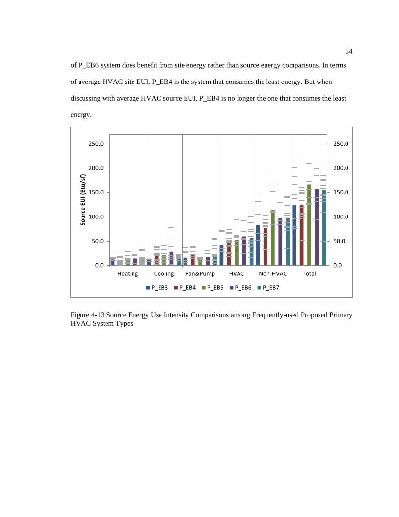
54
of P_EB6 system does benefit from site energy rather than source energy comparisons. In terms
of average HVAC site EUI, P_EB4 is the system that consumes the least energy. But when
discussing with average HVAC source EUI, P_EB4 is no longer the one that consumes the least
energy.
Figure 4-13 Source Energy Use Intensity Comparisons among Frequently-used Proposed Primary
HVAC System Types
0.0
50.0
100.0
150.0
200.0
250.0
0.0
50.0
100.0
150.0
200.0
250.0
Heating Cooling Fan&Pump HVAC Non-HVAC Total
Sou
rce
EU
I (B
tu/s
f)
P_EB3 P_EB4 P_EB5 P_EB6 P_EB7

55
(a)
(b)
Figure 4-14 Comparisons of (a) heating site EUI and (b) heating source EUI in frequently-used
proposed HVAC systems
76543
50
40
30
20
10
0
P_EB
EU
I (k
Btu
/sq
ft)
95% CI for the Mean
Heating Site EUI
76543
50
40
30
20
10
0
P_EB
EU
I (k
Btu
/sq
ft)
95% CI for the Mean
Heating Source EUI

56
However, it is quite common to understand that the locations of these frequently-used
proposed HVAC systems may affect the heating or cooling consumption. For example, large
heating EUI may result from not only different HVAC system type, but also large heating
demand due to large degree days. In order to compare these frequently-used HVAC systems
without factor of weather conditions or locations, weather normalized heating source EUI
(heating source EUI divided by heating degree days) and weather normalized cooling source EUI
(cooling source EUI divided by cooling degree days) are compared among these five frequently-
used HVAC systems in Figure 4-15. In terms of weather normalized source EUI, P_EB3 and
P_EB4 systems seem to have similar and less energy consumption than P_EB5, 6, and 7 systems.
P_EB5 system has the highest cooling consumption but not that high heating consumption. This
means it is better to use this system in cold climate regions to minimize the cooling consumption
and make use of its heating efficiency for medium size office buildings. On the contrary, it is
better to use P_EB6 in the mild or hot climate regions to minimize the heating consumption and
make use of its cooling efficiency for medium to large office buildings. Besides, the simplicity of
heating system of P_EB6 is a great advantage for large office buildings in mild and hot climate
regions. The application for P_EB7 systems is similar to P_EB5, but it can be used more for large
office buildings.

57
(a)
(b)
Figure 4-15 Comparisons of (a) weather normalized heating source EUI and (b) weather
normalized cooling source EUI in frequently-used proposed HVAC systems
76543
10
5
0
P_EB
We
ath
er
No
rma
lize
d E
UI
(Btu
/sq
ft/
de
gre
e d
ay
) 95% CI for the Mean
Weather Normalized Heating Source EUI
76543
12
6
0
P_EB
We
ath
er
No
rma
lize
d E
UI
(Btu
/sq
ft/
de
gre
e d
ay
) 95% CI for the Mean
Weather Normalized Cooling Source EUI

58
Conclusively, CAV heat pump system (P_EB4) has the least average HVAC site EUI and
the least average weather normalized heating site EUI than the other systems. In terms of site
energy use intensity, P_EB3 and 4 systems are almost all used for buildings under 25,000 ft2.
P_EB3 and 4 systems can have wide application in most climate regions. Most P_EB5 systems
are used for buildings which are less than 50,000 ft2, and better for cold and mild climate regions
to minimize the heating consumption. Most of P_EB6 and 7 systems are used for buildings
between 25,000 ft2 and 100,000ft
2. P_EB6 systems have a great advantage in mild and hot
climate regions, while P_EB7 systems are better used for mild and cold climate regions. When
comparing with source EUI, the heating consumption differences of frequently-used HVAC
systems are not as much as those in the comparison with site EUI. P_EB3 and 4 systems seem to
use less energy than P_EB5, 6, and 7 systems. Comparisons with weather normalized source EUI
support the system application summarized by comparisons with weather normalized site EUI.
Among all the frequently-used proposed HVAC systems, Non-HVAC EUI is a major
contributor to differing energy intensity clusters except P_EB7 system. Not all frequently-used
proposed HVAC systems show significantly different HVAC consumption in three clusters.
P_EB4 has significant HVAC EUI increase (due to cooling) from the low cluster to the medium
cluster, and P_EB7 has significant HVAC EUI increase (due to all HVAC end uses) from the
medium cluster to the high cluster.

59
Chapter 5
Energy Saving Characteristics
Chapter 4 focuses on proposed designs of using frequently-used HVAC system types,
and uses energy intensity clusters, which combine building characteristics and energy
consumption characteristics, to compare the energy consumption pattern among those frequently-
used proposed HVAC system types. This chapter will concentrate on the energy saving
characteristics, especially the HVAC energy saving of those frequently-used proposed HVAC
system types in different clusters.
5.1 Energy Saving Overview
Exploring the energy saving characteristics provides a supplemental approach to identify
the energy consumption pattern of those frequently-used proposed HVAC system types. The
energy savings of those frequently-used proposed HVAC systems are obtained by comparing
their proposed energy use intensities with their baseline energy intensities. Herein, the energy
saving means the energy saving ratio, which is used to quantify the amount of energy saved. It is
calculated by the ratio of energy reduction to the baseline total energy consumption. For example,
the HVAC energy saving means the HVAC consumption reduction divided by the baseline total
energy consumption. Figure 5-1 compares total energy saving and Non-HVAC saving. Based on
the median and major distribution, total energy saving in the low intensity cluster is higher than
those in the medium and high cluster. In one word, this difference may come from the building
size difference among the clusters. Low energy cluster buildings have about half of the building
sizes of medium and high clusters, which lead to more energy saving by implementing some

60
measures without limitations of large cost due to large building size or large building surface
area, for example, envelop insulation. The same building size characteristics in medium and high
clusters might also explain the similar major HVAC saving distribution – from 10% to 22%,
although the medium cluster has a larger variation in the HVAC saving. In another word, the low
energy cluster has the lowest Non-HVAC energy use than the other two clusters (shown in Figure
5-2), so the same Non-HVAC saving ratio matters more in medium and high energy cluster
buildings. Non-HVAC energy saving does not vary that significantly among three clusters. Low
intensity cluster has slightly more Non-HVAC saving than the medium intensity cluster, and the
high intensity cluster has slightly less Non-HVAC saving than the medium cluster. But basically
the median Non-HVAC saving is around 10%, and the Non-HVAC saving mainly comes from
lighting load reduction for these LEED certified buildings. In each cluster, proposed Non-HVAC
EUI accounts for over 50% of proposed total EUI. If plug load can be further reduced, it can help
the building to realize a position in a lower energy intensity cluster.
Figure 5-1 Box Plot of Energy Saving by Cluster
Cluster
Total_Energy_SavingHVAC_SavingNon-HVAC_Saving
321321321
70.0%
60.0%
50.0%
40.0%
30.0%
20.0%
10.0%
0.0%
Da
ta
Boxplot of Energy Saving by Cluster

61
Figure 5-2 Box Plot of Proposed Non-HVAC EUI by Cluster
The large HVAC saving is noticeable, which indicates the major part of total energy
saving comes from HVAC consumption reduction. Still under the scope of clusters, energy
saving characteristics of three end uses will be compared among those frequently-used proposed
HVAC system types.
5.2 Energy Saving Characteristics by Cluster
HVAC energy saving characteristics is examined by comparing the heating, cooling, and
fan and pump saving among different frequently-used proposed HVAC system types by clusters.
Buildings with almost all Non-HVAC saving and little HVAC saving are excluded from the
comparisons. Table 5-1summarizes the percentage of buildings with each energy end use saving
dominated in each cluster. Generally, about 50% of buildings using frequently-used proposed
HVAC system types are heating saving dominated, which means the heating saving accounts for
over 50% of HVAC saving. In each energy use intensity cluster, heating saving dominated
Cluster
Proposed_Total_EUIProposed_Non_HVAC_EUI
321321
90
80
70
60
50
40
30
20
10
0
Da
ta
Boxplot of Proposed Non-HVAC_EUI and Proposed Total_EUI

62
buildings are close to 50%. It could be a little bit different in low energy cluster that fan and
pump saving dominated buildings are twice more than cooling saving dominated buildings, while
in the medium and the high intensity clusters, the number of cooling saving dominated and fan
and pump saving dominated buildings are almost equivalent. This indicates that LEED certified
office buildings focus more on heating consumption reduction.
Table 5-1 Percentage of buildings with each energy end use saving dominated in each cluster
Energy end use saving dominated
Heating Cooling Fan and Pump
Low Cluster 55% 14% 32%
Medium Cluster 44% 30% 26%
High Cluster 56% 22% 22%
Overall 49% 24% 27%
HVAC energy saving characteristics in low cluster is much more important because this
cluster has the largest HVAC energy savings. Figure 5-3 compares the energy saving of those
frequently-used HVAC systems in the low intensity cluster.
Figure 5-3 HVAC Saving in Low Energy Cluster
-15.0%
-5.0%
5.0%
15.0%
25.0%
35.0%
45.0%
55.0%
65.0%
75.0%
3 3 3 3 3 4 4 4 4 4 4 4 4 4 4 4 6 6 6 7 7
Heating_Saving Cooling_Saving FanandPump_Saving Non-HVAC_Saving

63
Both large heating saving and large fan and pump saving patterns exist in the P_EB4
CAV heat pump system category, which is the major proposed system type in the low intensity
cluster.
The first P_EB4 system has the largest HVAC saving and largest heating saving. Both of
these two savings are over 60%. The baseline HVAC system type of this building is No.6 – VAV
DX cooling and electric reheat. The heating type was changed from electric resistant heating to
heat pump heating. The building is in the 5A cold and humid region. It is possible to have large
heating energy reduction because of high COP of heat pump systems. But it is questionable that
whether the heating type modification alone can result in over 60% of heating energy saving.
Both the second and the fourth P_EB4 systems were both changed from baseline No.3 CAV DX
cooling and furnace heating. The second P_EB4 system has a 13% better efficiency furnace as
supplemental heating. The fourth P_EB system has an equal heating efficiency boiler in the
propose water source heat pump system comparing to the baseline system. However, it is
somehow possible to explain the second P_EB4 system to have 30% more heating saving based
on a 13% of better heating efficiency and less than half of cooling degree days. But the extremely
high heating saving cannot just rely on the HVAC system type modification or energy efficiency
improvement. The third and the fifth P_EB4 systems have the same CAV heat pump system type
in the baseline and proposed designs. Because these two buildings use geothermal heat pump
systems, which can have higher energy efficiency in the proposed HVAC systems, their heating
saving are not as high as the first and the second P_EB4 systems. Building with different HVAC
system type from the baseline to the proposed design does not mean it will have more energy
saving. The fourth P_EB4 was changed from No.3 baseline system, while the fifth P_EB4 uses
the same CAV heat pump system, but they have almost the same heating saving.
Actually, it cannot be ignored that the envelop system improvement also makes
contribution in HVAC energy saving in these two buildings. For example, better insulation on

64
walls and roofs, and window upgrades can help to reduce heating consumption. Different levels
of envelop system improvement can bring in different energy saving. Even the climate region can
also somehow affect the heating saving. When comparing two of the same types of heat pump
systems with the same insulation improvement, there is high possibility that the one in a colder
region will have more heating saving.
High fan and pump saving patterns also happen in P_EB4 systems. The sixth, seventh,
and eighth P_EB4 systems use the same heat pump baseline systems. Large fan and pump energy
saving benefit from dedicated outdoor air system design, and demand control ventilation.
Large cooling saving is not common in the low energy cluster. The tenth P_EB4 system
has over 10% of cooling saving possibly because of using multi-VRF heat recovery systems. The
great cooling saving of the second P_EB7 system could benefit from changing the small DX AC
unit to a higher efficiency chiller. Normally, lighting load reduction can help reduce cooling
consumption. Better envelop insulation can reduce heat transfer out of the buildings. But it
happens sometimes that more cooling is needed which somehow prohibit cooling saving.
Both large heating saving and large fan and pump saving also exist in P_EB3 systems of
the low intensity cluster. Four P_EB3 systems use the same baseline No.3 system type. One
P_EB3 is switched from a No.5 baseline system. Normally, a CAV DX cooling with furnace
system serves one thermal zone. It would be unrealistic for a 30,000 ft2 building to switch from
baseline No.5 multi-zone VAV DX cooling and boiler heating system to No.3 system type unless
the building does not have many thermal zones and proper space to locate the package units.
Similarly, the cooling and heating efficiency improvement, from baseline designs to proposed
designs, is quite common in LEED certified buildings. These five buildings implemented
different options of envelop system upgrade. That’s part of the reason that different heating
saving can be obtained. One of P_EB3 system has large fan and pump saving but small heating
saving and almost no cooling saving. It is similar to those fan and pump dominated P_EB4

65
systems. Large fan and pump energy saving not only benefits from heating or cooling saving, but
also follows the large Non-HVAC saving (from 13% to 18.5%).
Three buildings using P_EB6 systems cover three different building sizes. The small size
building changed its baseline No.4 heat pump system to the proposed VAV DX cooling and
electricity heating system. Heat pump systems are high efficiency systems but also come with
high first cost. Because the building is in hot and humid region, small heating demand makes it
possible for the building to select electric heat and pursue high fan and pump energy saving by
using a multi-zone VAV system. The window upgrade and lighting load reduction also help to
reduce the cooling load. The other two sizes of buildings selected the same No.6 baseline HVAC
systems. The hot and humid climate condition makes it possible for the large size building to use
electric heat. The other medium office building is in a cold and dry climate region, which is an
example to show the application of VAV DX cooling and electric heating in a cold climate. The
heating and cooling savings come from the envelop system improvement and cooling efficiency
increase.
VAV chiller and boiler systems are not common in the low intensity cluster. Two office
buildings, a medium size and a large size, are good cases to show the possibility for buildings
with central plant to be in the low energy cluster. Both chillers are air cooled, which can save fan
and pump energy for heat rejection. In hot and dry climate regions, window upgrade of reducing
U-value and SHGC can obtain cooling saving, while in a cold climate region, this improvement
can help to save heating consumption.
By deeply looking at the energy saving in the low energy intensity cluster, some common
characteristics are concluded:
It is common to see proposed HVAC systems have better heating and cooling efficiency.
Table 5-2 summaries those frequently-used proposed HVAC systems and their corresponding
baseline HVAC system types. Most of the frequently-used proposed HVAC system types have
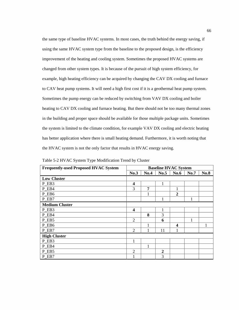
66
the same type of baseline HVAC systems. In most cases, the truth behind the energy saving, if
using the same HVAC system type from the baseline to the proposed design, is the efficiency
improvement of the heating and cooling system. Sometimes the proposed HVAC systems are
changed from other system types. It is because of the pursuit of high system efficiency, for
example, high heating efficiency can be acquired by changing the CAV DX cooling and furnace
to CAV heat pump systems. It will need a high first cost if it is a geothermal heat pump system.
Sometimes the pump energy can be reduced by switching from VAV DX cooling and boiler
heating to CAV DX cooling and furnace heating. But there should not be too many thermal zones
in the building and proper space should be available for those multiple package units. Sometimes
the system is limited to the climate condition, for example VAV DX cooling and electric heating
has better application where there is small heating demand. Furthermore, it is worth noting that
the HVAC system is not the only factor that results in HVAC energy saving.
Table 5-2 HVAC System Type Modification Trend by Cluster
Frequently-used Proposed HVAC System Baseline HVAC System
No.3 No.4 No.5 No.6 No.7 No.8
Low Cluster
P_EB3 4 1
P_EB4 3 7 1
P_EB6 1 2
P_EB7 1 1
Medium Cluster
P_EB3 4 1
P_EB4 8 3
P_EB5 2 6 1
P_EB6 1 4 1
P_EB7 2 1 11 1
High Cluster
P_EB3 1
P_EB4 1
P_EB5 2 2
P_EB7 1 3
67
Envelop system upgrades, such as improving the wall, roof insulation, using better
windows to decrease the window U-value and SHGC, modifying window wall ratio if it is a new
building design, etc. can also bring in heating or cooling saving. The energy saving varies in
different climate regions. For instance, the window upgrade in a hot climate area often saves
more cooling, but in a cold region it may save more heating consumption.
Non-HVAC load reduction, such as lighting load reduction can help to reduce cooling
use. Some of the fan and pump energy saving also benefit from the lighting load reduction. If
other Non-HVAC load could be further decreased it can have a great impact on the building to
get a spot in a lower energy intensity cluster.
Energy saving characteristics in medium and high clusters is similar to that in low
intensity cluster. Figure 5-4 and Figure 5-5 compare the energy saving of those frequently-used
HVAC system types in the medium and higher clusters, respectively. Heating saving dominated
cases and fan and pump saving dominated cases are still common to see, but the number of
cooling saving dominated cases is more than that in the low intensity cluster. The core zone
accounts for a significant proportion in large size buildings. It is more obvious to see high cooling
saving due to the cooling efficiency improvement in these two clusters. Figure 5-6 compares the
average energy saving of those frequently-used HVAC systems in different clusters. In the low
intensity cluster, smaller building size makes it easier to improve the envelop system than that for
larger size of buildings. Medium and high cluster buildings still have large room to improve Non-
HVAC energy saving.

68
Figure 5-4 Energy Saving in Medium Energy Cluster
Figure 5-5 Energy Saving in High Energy Cluster
-15.0%
-5.0%
5.0%
15.0%
25.0%
35.0%
45.0%
55.0%
65.0%
75.0%
3 3 3 3 3 4 4 4 4 4 4 4 4 4 4 4 5 5 5 5 5 5 5 5 5 6 6 6 6 6 6 6 7 7 7 7 7 7 7 7 7 7 7 7 7 7 7
Heating_Saving Cooling_Saving FanandPump_Saving Non-HVAC_Saving
-15.0%
-5.0%
5.0%
15.0%
25.0%
35.0%
45.0%
55.0%
65.0%
75.0%
3 4 5 5 5 5 7 7 7 7
Heating_Saving Cooling_Saving FanandPump_Saving Non-HVAC_Saving

69
Figure 5-6 Average Energy Saving Comparisons of Frequently-used HVAC System Types in
Different Clusters
5.3 Energy Saving Analysis
One important point to note is that whether HVAC system type is changed or not from
the baseline to the proposed design is not the only factor, or may not even be the factor, which
results in energy savings. Beside this, envelop system upgrade, lighting load reduction (Non-
HVAC EUI reduction), and HVAC system efficiency upgrade may also be the factors. Table 5-3
summarizes the percentage differences of these parameters. This result provides energy modelers
comparison with their projects and let them know how much each of these parameters can be
changed in proposed designs. Buildings in low intensity cluster are higher efficient than those in
the medium and the high clusters. The reason is because they have better upgrade of window U-
0.0%
5.0%
10.0%
15.0%
20.0%
25.0%
30.0%
35.0%
40.0%
45.0%
Heating_Saving Cooling_Saving FanandPump_Saving Non-HVAC_Saving

70
value, wall U-value, roof U-value, and heating COP, as well as more lighting load reduction (bold
in Table 5-3).
Table 5-3 Percentage Difference of Investigated Parameters in Three Clusters
Low Cluster Medium Cluster High Cluster
Mean Median StDev Mean Median StDev Mean Median StDev
% Δ SHGC -23% -24% 22% -18% -20% 29% -24% -25% 19%
% Δ Window U -37% -42% 24% -27% -25% 26% -34% -28% 25%
% Δ Wall U -40% -46% 32% -36% -38% 29% -40% -38% 27%
% Δ Roof U -48% -52% 28% -40% -47% 27% -29% -25% 23%
% Δ Cooling COP 16% 14% 19% 19% 14% 27% 22% 16% 25%
% Δ Heating COP 48% 18% 99% 8% 7% 21% 3% 5% 19%
% Δ Non-HVAC EUI -21% -20% 13% -16% -13% 12% -11% -10% 8%
Note: The minus sign means the parameter decreasing in the proposed case.
This part of analysis focuses on identifying the key parameters that brings in the energy
savings. Multiple regression analysis is the important tool in this study. Figure 5-7 shows the
workflow of this multiple regression analysis. The differences of cooling, heating, and HVAC
EUI from the baseline to the proposed are the responses. All parameters that change from the
baseline to the proposed cases are included in this analysis as predictors and categorized into four
different types: (1) envelop upgrade – differences of SHGC, window U-value, wall U-value, and
roof U-value; (2) Non-HVAC EUI change – most of which is lighting load reduction; (3) HVAC
efficiency change – heating and cooling efficiency upgrade; (4) HVAC system change – whether
the HVAC system type is changed from the baseline to the proposed cases. MRA is conducted
within three scopes: (1) three energy use intensity; (2) five frequently-used proposed HVAC
systems; and (3) subset of buildings with completed information of all predictors. At first, all
predictors are included in the MRA. If the R-sq value is at least close to 50%, overall P value
needs to be checked. If overall P value is larger than 0.1, the predictor with largest individual P
value should be eliminated and MRA is conducted again. Otherwise the MRA is rejected. When
individual P value is less than 0.05, it means the predictor has significant impact on the variance
of the response. When individual P value is between 0.05 and 0.1, it means the predictor has
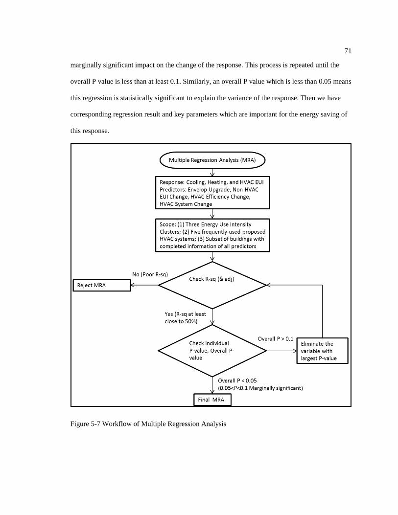
71
marginally significant impact on the change of the response. This process is repeated until the
overall P value is less than at least 0.1. Similarly, an overall P value which is less than 0.05 means
this regression is statistically significant to explain the variance of the response. Then we have
corresponding regression result and key parameters which are important for the energy saving of
this response.
Figure 5-7 Workflow of Multiple Regression Analysis

72
Table 5-4 and Table 5-5 show the results of MRA. MRA shows better results if it is
conducted by looking at different frequently-used proposed HVAC system types than by different
clusters. MRA results could be meaningless if looking at all buildings together. It is a poor
regression result for low energy intensity clusters which does not mean buildings in the low
intensity cluster don’t rely on these predictors. It is because each of these clusters is a mix of
different HVAC system types and these systems have different key predictors which makes it a
poor regression result for low energy intensity cluster. High intensity cluster has a better
regression result because different HVAC system types may share similar key predictors. A
subset of buildings of each frequently-used proposed HVAC system type has different regression
result from that of original buildings using the same system type. The reason is that original
group of buildings has different missing information. Some parameter is assessed as a (key)
predictor. It could be because that most buildings have information of this parameter. The
different amount of information in different parameters can affect assessment of the predictors.
That is why a subset of buildings with completed information of all parameters is used.
Parameters of envelop system upgrade are more assessed as predictors and key predictors
in this MRA. It presents the importance of envelop upgrade when comparing with other type of
predictors. P_EB 3 and P_EB4 systems are more used in small and medium office buildings. For
P_EB3 systems, roof is more important than the other parameters in envelop systems. But for
P_EB4 systems, window and wall are more important. P_EB5, 6, and 7 systems are more used in
medium and large office buildings. For buildings using these three systems, window and SHGC
are more essential than wall and roof. HVAC efficiency upgrade is different from system to
system. Basically, HVAC efficiency upgrade is more important for buildings using P_EB5, 6, and
7 systems than P_EB3 and 4 systems. Since P_EB6 and 7 systems are mostly for medium and
large buildings, lighting load reduction and keeping the same HVAC system types are more
important than those buildings using P_EB3, 4, and 5 systems.
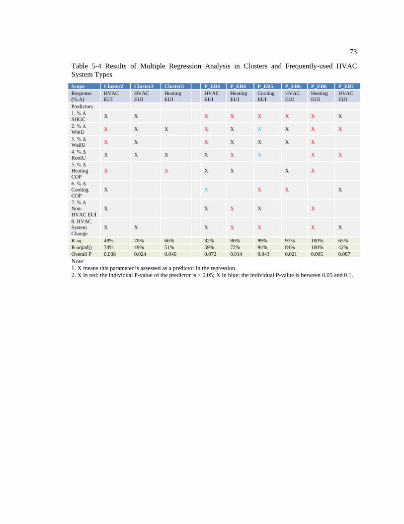
73
Table 5-4 Results of Multiple Regression Analysis in Clusters and Frequently-used HVAC
System Types
Scope Cluster2 Cluster3 Cluster3 P_EB4 P_EB4 P_EB5 P_EB6 P_EB6 P_EB7
Response
(% Δ)
HVAC
EUI
HVAC
EUI
Heating
EUI
HVAC
EUI
Heating
EUI
Cooling
EUI
HVAC
EUI
Heating
EUI
HVAC
EUI
Predictors
1. % Δ
SHGC X X
X X X X X X
2. % Δ WinU
X X X
X X X X X X
3. % Δ
WallU X X
X X X X X
4. % Δ
RoofU X X X
X X X X X
5. % Δ
Heating
COP
X X
X X
X X
6. % Δ
Cooling COP
X
X X X
X
7. % Δ
Non-
HVAC EUI
X
X X X
X
8. HVAC System
Change
X X
X X X
X X
R-sq 48% 70% 66% 82% 86% 99% 93% 100% 65%
R-aq(adj) 34% 49% 51% 59% 72% 94% 84% 100% 42%
Overall P 0.008 0.024 0.046 0.072 0.014 0.043 0.021 0.005 0.087
Note:
1. X means this parameter is assessed as a predictor in the regression.
2. X in red: the individual P-value of the predictor is < 0.05; X in blue: the individual P-value is between 0.05 and 0.1.

74
Table 5-5 Results of Multiple Regression Analysis in Subset of Buildings of Each Frequently-
used HVAC System Types
Scope P_EB3* P_EB3* P_EB4* P_EB4* P_EB5* P_EB5* P_EB6* P_EB6* P_EB6* P_EB7* P_EB7* P_EB7*
Response
(% Δ)
HVAC
EUI
Heating
EUI
HVAC
EUI
Heating
EUI
Heating
EUI
Cooling
EUI
HVAC
EUI
Heating
EUI
Cooling
EUI
HVAC
EUI
Heating
EUI
Cooling
EUI
Predictors
1. % Δ
SHGC X X X X X X X
2. % Δ WinU
X X X X X X X X X X
3. % Δ
WallU X X X X X
4. % Δ
RoofU X X X X X X X
5. % Δ
Heating
COP
X X X X
X
6. % Δ
Cooling COP
X X
X X
X
7. % Δ
Non-
HVAC EUI
X X X X X
8. HVAC
System
Change
X X X X X X
R-sq 80% 86% 76% 93% 85% 48% 97% 100% 54% 65% 87% 64%
R-aq(adj) 67% 77% 55% 86% 69% 38% 91% 100% 39% 44% 71% 43%
P 0.087 0.051 0.048 0.001 0.097 0.084 0.02 0.02 0.098 0.086 0.041 0.091
Note:
1. X means this parameter is assessed as a predictor in the regression.
2. X in red: the individual P-value of the predictor is < 0.05; X in blue: the individual P-value is between 0.05 and 0.1.
3. * means it is a subset of buildings with completed predictor information.
Conclusively, buildings in low energy use intensity have the most energy savings while
buildings in high energy use intensity have the least. The reason is because these buildings have
better upgrade of window U-value, wall U-value, roof U-value, and heating COP, as well as more
lighting load reduction. The percentage differences of these parameters are summarized by three
clusters. This provides energy modelers comparison with their projects and let them know how
much each of these parameters can be changed in proposed designs. By applying multiple
regression analysis, the key parameters in HVAC energy savings are investigated. Envelop
upgrade is more important than HVAC efficiency upgrade, lighting load reduction and HVAC
system change. The latter three are assessed as different key factors for HVAC energy savings
regarding different HVAC system types. Close to 50% of buildings using frequently-used HVAC

75
system types focus more on heating than cooling and fan and pump to realize over 50% of HVAC
energy savings, which is almost the same case even in each of three energy use intensity clusters.
Non-HVAC EUI covers over 50% of total EUI, but the major part of total energy savings is from
HVAC energy savings. Besides lighting load reduction, more Non-HVAC energy savings should
be encouraged.

Chapter 6
Case Study
The main objective of case study is to compare the energy consumptions of different
HVAC system types, and test energy savings by lighting load reduction and envelop system
upgrade though the energy model of an actual office building.
6.1 Building and HVAC System Description
Built in the 1973, the case study building is an actual office building in Philadelphia. It is
a large office building with ten stories above the ground (215,000 ft2) and three floors of parking
space mainly underground. The building has a total annual energy use intensity of 86.0 kBtu/ft2
(without parking) based on 2014 utility bills. It is in the high energy intensity cluster. Figure 6-1
shows the actual building.

77
Figure 6-1 Case Study Building (Credit: Google Maps)
The HVAC system type of this case study building is VAV with chiller and boiler, which
is a frequently-used HVAC system type for a large office building. The building has a two-tower
structure. Two multi-zone VAV air handling units with hot water reheat serves each of the
towers. The building is heated by two boilers of 83% rating efficiency and two chillers. Two
cooling towers are tied to both of the chillers.
An energy model with 74 VAV terminal units with hot water reheat has been built for the
case study building. The energy simulations are run on EnergyPlus simulation software. Figure
6-2 shows the screenshot of the energy model for the case study building. The lighting, plug load,
cooling, heating and total electricity consumption of the model has been calibrated with meter
data. The calibration results, Coefficient of Variation of the Root Mean Squared Error and
Normalized Mean Bias Error (CVRSME and NMBE), fall in the monthly calibration requirement.
Figure 6-2 Screenshot of Energy Model for the Case Study Building

78
6.2 HVAC System Change
The original HVAC system type is VAV chiller and boiler. The test is conducted by
changing the HVAC system type to 3 VAV DX cooling and boiler systems. The only difference
is the cooling type and cooling COP. The chiller COP is 6.0. The DX low speed COP is 4.0 and
its high speed COP is 3.0. All the other set point, schedule, load density settings are kept the
same. Table 6-1 compares energy consumption of the case study with original HVAC system
type and No.5 VAV DX cooling and boiler type. More cooling is needed because the COP
reduction. The fans consumption has almost no change. Pumps have great energy saving because
the No.5 system does not have a chiller and water loop system; the pump energy get significantly
reduced. Since there is no chiller in the system, the system does not need cooling tower to reject
the heat. Finally, the total electricity has 7.4% of savings, but the heating uses 8.2% more energy.
Table 6-1 Energy consumption of Different HVAC System Types
End Use
2xNo.7 3xNo.5
Energy Use Energy Use End Use Energy Saving
Cooling (kBtu) 1350470 2447769 -6%
Heating (kBtu) 8844000 9588000 -4%
Interior Lighting (kBtu) 2201422 2201422 0%
Interior Equipment (kBtu) 4723232 4723232 0%
Fans (kBtu) 313802 307967 0%
Pumps (kBtu ) 1192494 22011 6%
Heat Rejection (kBtu) 681035 0 4%
Total Energy (kBtu) 19306454 19290401 0%
6.3 Lighting Load Reduction and Envelop Upgrade
With the new HVAC system type in the model for the case study building, further
simulations of adding lighting load reduction and envelop upgrade step by step can be tested.

79
Figure 6-3 presents the energy consumption of the base model and after each step change. In the
base model, over 50% of total energy is consumed by HVAC system. This is different from
LEED NC certified office buildings, which consume over 50% of total energy for Non-HVAC
systems. There is almost no total energy savings due to HVAC system type change. Table 6-2
compares the end use energy savings and total energy savings of three step changes with the
original model. 53% of lighting load reduction is first added to the model, which results in 5% of
interior lighting saving, but 5% of more cooling consumption, and 5% of more heating
consumption. Fans energy saving can also benefit a bit from lighting load reduction. Pump energy
use increases a little due to the increase of heating. Then envelop system is upgraded from the
CBECS pre-1980 construction set to the ASHRAE Standard 189 high performance building
construction set, which can only result in 3% of more cooling use but 15% of huge heating
savings. 27% of total energy saving is obtained, which seems to be a great improvement. Thus,
HVAC system change brings almost no total energy saving. A large amount of lighting load
reduction results in a small lighting energy savings which is reasonable for large office buildings.
The envelop upgrades have more impact on total energy savings than lighting load reduction.
These results basically verify the energy saving characteristics.
Figure 6-3 Energy Consumption Comparisons of Case Study
0
5000
10000
15000
20000
25000
Base Case Step 1 Step 2 Step 3
En
erg
y U
se (
MB
tu) Heat Rejection
Interior Equipment
Pumps
Fans
Interior Lighting
Heating
Cooling

80
Table 6-2 Energy consumption of Further Lighting Load Reduction and Envelop Upgrade
Base Case Step 1 Step2 Step 3
2xNo.7 3xNo.5 3xNo.5+LLR(-53%) 3xNo.5+LLR(-53%)+EU
End use
and
total energy savings
Cooling saving
Heating saving
Fan saving
Pump saving
Lighting saving
Interior equipment saving
Heat rejection saving
-6%
-4%
0%
6% 0%
0%
4%
-5%
-5%
0%
6%
5% 0%
4%
-3%
15% 0%
6%
5%
0%
4%
Total energy saving 0% 5% 27%
Chapter 7
Conclusions and Future Work
This thesis identified the frequently-used HVAC system types for high performance
office buildings and enabled them in the energy consumption analyses. The thesis explored the
frequently-used proposed HVAC system types of 134 LEED NC certified office buildings. This
study first analyzed the energy consumption characteristics for frequently-used proposed HVAC
system types in different clusters; then it compared the energy saving characteristics of those
frequently-used proposed HVAC system types by cluster. Finally, the study justified the energy
consumption patterns of different HVAC system types through a case study of an actual office
building
7.1 Thesis Conclusions
The major thesis conclusions are as follows:
1. Frequently-used proposed HVAC systems in 134 LEED NC certified office buildings
are CAV with DX cooling and furnace heating, CAV heat pump system with other supplemental
heating, VAV DX cooling and boiler, VAV with DX cooling and electric heating, and VAV with
chiller and boiler. They are represented as P_EB3, 4, 5, 6, and 7 systems because they are
equivalent to baseline No.3, No.4, No.5, No.6 and No.7 HVAC systems of ASHRAE Standard
90.1.
2. P_EB4 systems have the least average HVAC site EUI and the least average weather
normalized heating site EUI than the other systems. The application of these frequently-used
proposed HVAC systems are summarized as: P_EB3 and 4 systems have wide application in
82
most climate regions for buildings under 25,000 ft2. Most P_EB5 systems are used for buildings
which are less than 50,000 ft2, and better for cold and mild climate regions to minimize the
heating consumption. Most of P_EB6 and 7 systems are used for buildings between 25,000 ft2
and 100,000ft2. P_EB6 systems have a great advantage in mild and hot climate regions, while
P_EB7 systems are better used for mild and cold climate regions. P_EB3 and 4 systems seem to
use less energy than P_EB5, 6, and 7 systems.
3. Non-HVAC EUI is a major contributor to differing different energy intensity clusters.
Not all frequently-used proposed HVAC systems show significantly different HVAC
consumption in three clusters. Non-HVAC EUI covers over 50% of total EUI, but the major part
of total energy savings is from HVAC energy savings. Besides lighting load reduction, more
Non-HVAC energy savings should be encouraged.
4. Buildings in low energy use intensity have the most energy savings while buildings in
high energy use intensity have the least. The reason is because these buildings have better
upgrade of window U-value, wall U-value, roof U-value, and heating COP, as well as more
lighting load reduction. The percentage differences of these parameters are summarized by three
clusters. This provides energy modelers comparison with their projects and let them know how
much each of these parameters can be changed in proposed designs. Multiple regression analysis
indicates that envelop upgrade is more important than HVAC efficiency upgrade, lighting load
reduction and HVAC system change.
5. Close to 50% of buildings using frequently-used HVAC system types focus more on
heating than cooling and fan and pump to realize over 50% of HVAC energy savings, which is
almost the same case even in each of three energy use intensity clusters.
6. The case study verifies the following results. HVAC system change brings almost no
total energy saving. A large amount of lighting load reduction results in a small lighting energy
83
savings which is reasonable for large office buildings. The envelop upgrades have more impact
on total energy savings than lighting load reduction.
7.2 Future Work
Frequently-used proposed HVAC system types of LEED certified office buildings
provided a valuable sample of high performance office buildings to explore the energy
consumption characteristics and energy saving characteristics. These energy consumption
patterns in high performance buildings pointed out not only the key areas that affect the energy
consumption characteristics, but also the directions that lead to potential energy savings for
retrofit in low performance office buildings. Future work can focus on the following parts:
(1) Based on the HVAC system typical modification trend, the large size case study
building limits the possibility of using the other HVAC system types except for the VAV DX AC
and boiler system, whereas a small or medium size building model can offer more diverse HVAC
system type tryouts.
(2) Tests of envelop element improvement (wall, window and roof) rather than the whole
envelop system upgrades, as well as in different climate regions, are much more helpful to
compare the different energy saving patterns.
(3) Analyses of actual energy consumptions data and more sufficient information of high
performance office buildings will provide a better understanding of their energy saving
characteristics.

References
Arthur D. Little, Inc. (1999). Energy Consumption Characteristics of Commercial Building
HVAC Systems Volume II: Thermal Distribution, Auxiliary Equipment, and Ventilation.
Arthur D. Little, Inc. (2001). Energy consumption characteristics of HVAC systems Volume I:
Chillers, Refrigerant Compressors, and Heating Systems.
ASHRAE. (2008). ASHRAE Handbook – HVAC Systems and Equipment.
ASHRAE. (2010). ASHRAE Standard 90.1-2010 Energy Standard for Buildings Except Low-Rise
Residential Buildings. ASHRAE.
ASHRAE. (2011). Advanced Energy Design Guide for Small to Medium Office Buildings.
Bojic, M., Nikolic, N., Nikolic, D., Skerlic, J., & Miletic, I. (2011). A simulation appraisal of
performance of different HVAC systems in an office building. Energy and Buildings,
1207-1215.
Chua, K., Chou, S., Yang, W., & Yan, J. (2013). Achieving better energy-efficient air
conditioning – A review of technologies and strategies. Applied Energy, 87-104.
Continuing Education and Development, Inc. (n.d.). Centralized Vs Decentralized Air
Conditioning Systems. Retrieved April 20, 2013, from CED engineering.com:
http://www.cedengineering.com/courseoutline.asp?cid=446
EIA. (1998). Retrieved April 10, 2013, from 1995 CBECS Survey Data:
http://www.eia.gov/consumption/commercial/data/1995/
EIA. (2006). Commercial Buildings Energy Consumption Survey (CBECS) 2003 Office buildings.
Heidarinejad, M., Dahlhausen, M., & Srebric, J. (2013). A Classification Methodology based on
Statistical Analyses of Energy Consumption Patterns to Identify Typical U.S. Office
Buildings. Applied Energy.

85
Higgins, J. A. (2012). Energy Modeling Basics. ASHRAE Journal, 26-30.
Korolija, I., Marjanovic-Halburd, L., Zhang, Y., & Hanby, V. I. (2011). Influence of building
parameters and HVAC systems coupling on building energy performance. Energy and
Buildings, 1247-1253.
Liu, X., & Hong, T. (2010). Comparison of energy efficiency between variable refrigerant flow
systems and ground source heat pump systems. Energy and Buildings, 584-589.
McQuay International. (2002, October). Why Water Source Heat Pump. Retrieved April 2013,
from Mcquay Engineering System Solution:
http://www.mcquay.com/mcquaybiz/literature/lit_systems/EngNews/1002.pdf
NREL, PNNL, LBNL, & DOE. (2011). U.S. Department of Energy Commercial Reference
Building Models of the National Building Stock.
Perez-Lombard, L., Ortiz, J., & Pout, C. (2008). A review on buildings energy consumption
information. Energy and Buildings, 394-398.
Pérez-Lombard, L., Ortiz, J., Coronela, J. F., & Maestre, I. R. (2011). A review of HVAC
systems requirements in building energy regulations. Energy and Buildings, 255-268.
Shahrestani, M., Yao, R., & Cook, G. K. (2013). Characterising the energy performance of
centralised HVAC&R systems in the UK. Energy and Buildings, 239-247.
Stanley A. Mumma. (2001). Dedicated Outdoor Air Systems. Retrieved April 2013, from
Dedicated Outdoor Air Systems & Radiant Ceiling Panels.
Sugarman, S. C. (2005). HVAC Fundamentals. Fairmont Press.
U.S. DOE. (2010). U.S. DOE Energy Efficiency & Renewable Energy. Retrieved 2013, from
Buildings Energy Data Book: http://buildingsdatabook.eren.doe.gov/ChapterIntro1.aspx
U.S. Green Building Council. (2014, January). U.S. Green Building Council. Retrieved October
2013, from U.S. Green Building Council: http://www.usgbc.org/sampleforms/v3

86
US Environmental Protection Agency. (2011). Methodology for Incorporating Source Energy
Use.
Wallace, M. (2012). Complying With ASHRAE Standard 90.1-2010: HVAC/Mechanical.
Retrieved May 2013, from 2012 Winter Conference Courses:
http://ali.ashrae.biz/2012winterconferencecourses/std90-1hvac-
mechanical/Complying_Std_90-1_HVAC-Mech_Chicago_2012_Final_Notes.pdf
Winiarski, D., Jiang, W., & Halverson, M. (2006). Review of Pre- and Post-1980 Buildings in
CBECS – HVAC Equipment.
Witte, M. J., & Henninger, R. H. (2006). Evaluating the Ability of Unitary Equipment to Maintain
Adequate Space Humidity Levels, Phase II.
Zhang, Y., Wright, J. A., & Hanby, V. I. (2006). Energy Aspects of HVAC System
Configurations—Problem Definition and Test Cases. HVAC&R Research, 871-878.


![Influence of daily beer or ethanol consumption on physical ... · consumption of beer, which is one of the most con-sumed beverages in the world [19, 20] and is frequently consumed](https://static.fdocuments.in/doc/165x107/60665c1ebd7e4300464e2698/influence-of-daily-beer-or-ethanol-consumption-on-physical-consumption-of-beer.jpg)