Energy and environmental benefits from inclusion-based ... slides/2… · •Flow-assurance issues...
30
Energy and environmental benefits from inclusion-based material technologies: the evolving gas hydrate story Kirk G. Osadetz 1 and Donald C. Lawton 1,2 1 CMC Research Institutes Inc., Containment and Monitoring Institute, 3535 Resaearch Drive N.W., Calgary, AB, T2LN 2K8 T: 403.210.7108, E: [email protected] 2 Department of Geoscience, University of Calgary, 2500 University Drive N.W., Calgary, AB, T2N 1N4 with contributions from the GSC Gas Hydrate Team: Scott Dallimore, Fred Wright, Michael Riedel, Roy Hyndman (Victoria); Zhuoheng Chen, Tom Brent (Calgary); Gilles Bellefleur (Ottawa); David Mosher (Dartmouth)
Transcript of Energy and environmental benefits from inclusion-based ... slides/2… · •Flow-assurance issues...

Energy and environmental benefits from inclusion-based material technologies: the evolving gas hydrate story
Kirk G. Osadetz1 and Donald C. Lawton1,2
1CMC Research Institutes Inc., Containment and Monitoring Institute, 3535 Resaearch Drive N.W., Calgary, AB, T2LN 2K8 T: 403.210.7108, E: [email protected] 2Department of Geoscience, University of Calgary, 2500 University Drive N.W., Calgary, AB, T2N 1N4 with contributions from the GSC Gas Hydrate Team: Scott Dallimore, Fred Wright, Michael Riedel, Roy Hyndman (Victoria); Zhuoheng Chen, Tom Brent (Calgary); Gilles Bellefleur (Ottawa); David Mosher (Dartmouth)


CMC Research Institutes: Field Research Station (sec. 22-017-16W4), Land courtesy Cenovus Energy
3-D Seismic Program Complete Soon to Spud CMC Countess #1, 500 m injector Stop on a Pre-meeting Geoconvention Field Trip And Core Presentation.

CMC Research Institutes: Newell County Field Research Station
• FRS is a globally unique facility. • Containment is critical for may subsurface applications including:
• Secure Carbon Storage; • SAGD steam chambers; • induced hydraulic fracturing; • induced seismicity; • water and acid gas disposal; • enhanced petroleum recovery; • groundwater protection; etc.
• There is a need to better characterize containment risks. • Learnings for many industries, as well as regulators and policymakers. • Computational models need better earth images/models. Web image from: “Fracking Canada”
Fluid expulsion accident initiated from a nearby well,
Innisfail AB

Outline 1. Characteristics of Gas Hydrate Science and Technology. 2. Global and Canadian GH Resources. 3. Mallik Gas Hydrate Drilling Programs and Results. 4. Athabasca CO2 Storage as Gas Hydrate. 5. Future GH opportunities globally and in Canada.
Outline

GH Structure & Energy Content
•GH is an ice-like solid (clathrate) composed of gas (guest) molecules in a cage of water (host) molecules that forms at low temperature and moderate pressure.
•Like ice, GHs require energy input to dissociate, which also is the source of “self-preserving” characteristics.
•CH4 and CO2 are the common, but not the only guest molecules.
•1 m3 of GH → 164 m3 of methane gas, equivalent to a dry gas reservoir at 16 Mpa, or a gas pool at 1.6 km depth.
•Gas hydrate has an energy content comparable to bitumen and tar sands. Energy content in SCF/ft3 of rock:
Gas Hydrate: 40 – 50 Coal Bed Methane: 8 –10 Tight/Shale gas: 5 –10

Inclusion-based Material Research Themes •Flow-assurance issues for pipeline transportation.
•A potential hazard to seafloor and permafrost facilities.
•A potentially commercial or strategic petroleum resource.
•Secure Carbon Storage of natural or anthropogenic CH4 and CO2.
•A potential environmental change agent (e.g. the clathrate gun hypothesis).
•A natural gas transportation mechanism that is potentially cheaper than LNG (~21 shipping days).
•A new purification technology (e.g. potable water from saline water).
•A model for “inclusion-based” materials science and technologies.

Why consider Gas Hydrates? • Low Natural Gas prices are regional not global.
• Asian economies face supply security issues, e.g. Japan produces 3% of its petroleum domestically.
• Marine gas hydrates impact national boundaries and territorial disputes.
•Some countries and corporations consider longer timelines where technological “game-changers” are possible (e.g. SAGD; HD+IHF).
• Japan’s “commercial” gas hydrate production accelerated Asian (China, S. Korea/Statoil, India) R&D programs.
• GHs provide a “technology transfer” business opportunity model.
•GH offer a unique combined cycle Arctic petroleum production + secure carbon storage opportunity.
GANS Project Areas, 2006-2010; Norwegian Continental Margin, Barents Sea, Western Svalbard Margin.

Modes of Gas Hydrate Occurrence Terrestrial Sub-Permafrost Accumulations
• Common in Arctic regions and identified by drilling. • Commonly part of a thermogenic petroleum system. • Thickest, richest, most accessible, potentially associated or co-
located with conventional natural gas in porous and permeable reservoirs.
• Preferred North American production target.
Sub-sea Marine Accumulations
• Common to continental shelves and slopes and detected using Bottom-Simulating-Reflections (BSR’s).
• Commonly part of a biogenic petroleum system. • Typically hosted in silt and shale dominated lithofacies. • Asian production target.
Seafloor Accumulations
• Discrete rich seafloor outcrop accumulations. • Not well characterized. • Not persistent due to concentration effects. • Possible Korean alternate production target.
Mallik Core onshore NWT
Hydrate Ridge offshore OR
Ice worms on GH o/c GOM

GH Stability Conditions OFFSHORE CONTINENTAL MARGIN ARCTIC PERMAFROST
0
400
1400
1200
200
1000
800
600
Temperature °C 0 20 10 -20 -10 30
1600
Metres
BASE OF GAS HYDRATE
Z O N
E O
F G
A S
H Y D
R A
T E
WATER SEDIMENT
PHASE BOUNDARY
METHANE HYDRATE
Metres
0
400
1400
1200
200
1000
800
600
1600 0
Temperature °C 20 10 -20 -10 30
BASE OF GAS HYDRATE
DEPTH OF PERMAFROST
SEDIMENT
PHASE BOUNDARY
GEOTHERMAL GRADIENT
METHANE HYDRATE
GRADIENT GEOTHERMAL
GEOTHERMAL GRADIENT
GEOTHERMAL GRADIENT

The “Calthrate Gun” is loaded with blanks Leonardo!
•Surface temperature forcing and conversion of a conventional gas pool to GH explains current observed GH and permafrost at the Mallik site (Case 1). This explains the observed gap between base IBP and top GH.
•Otherwise permafrost grows downward through GH and the two are intermingled (Case 2) and the surface temperature model does not predict the observed base of either IBP or GH. •The GH and IBP layers respond to surface temperature forcing they do not lead or anticipate it. Permafrost buffers GH dissociation. The role of GH in climate cycles is complicated and delayed by thermal inertia and the enthalpies of melting and dissociation.

Global & Canadian GH Resources: There is lots
Arctic Archipelago (Onshore and Offshore) 671 to 21,886 TCF
Atlantic Margin, apparently rare, but large area 671 to 2,753 TCF
Pacific Margin, apparently
common, 113 to 847 TCF
Total in-situ amount of methane in gas hydrates is estimated to be 1,553 to 28,593 TCF (0.44 to 8.1 x 10¹⁴ m3), compared to a conventional gas potential of ~953 TCF (0.27 X 10¹⁴ m3).
Baffin-Ellesmere Margin, stable on shallow shelf and in Lancaster Sd., but no estimate
Amerasian Basin Margin - no estimate, but identified
Mackenzie Delta (Onshore and Offshore) ~250-300 TCF
Scotian Margin, restricted to outer shelf
Mallik

GH Production Strategies ARCTIC PERMAFROST
0
400
1400
1200
200
1000
800
600
Temperature °C 0 20 10 -20 -10 30
1600
Metres
BASE OF GAS HYDRATE
Z O N
E O
F G
A S
H Y D
R A
T E
WATER SEDIMENT
PHASE BOUNDARY
METHANE HYDRATE
Metres
0
400
1400
1200
200
1000
800
600
1600 0
Temperature °C 20 10 -20 -10 30
BASE OF GAS HYDRATE
DEPTH OF PERMAFROST
SEDIMENT
PHASE BOUNDARY
GEOTHERMAL GRADIENT
METHANE HYDRATE
GRADIENT GEOTHERMAL
GEOTHERMAL GRADIENT
•Adaptation of available methods rather than entirely new technologies.
•General consensus to destabilize GH in situ and produce natural gas, although some still propose mining sea floor accumulations.
•Pressure reduction and dissociation using ambient heat transfer is the easiest and cheapest. Only borehole pressure drops have been employed, but gas or water production are potential enhancements.
•Thermal, hot water, or Chemical “freezing point-depression” stimulation could work, and may enlarge the area of pressure reduction effects.
•Guest gas displacement, CO2 will displace CH4 from the lattice.

Carbon Neutral GH Power Generation? •The Ikhil conventional pool that supplies Inuvik is declining. GHs in Mackenzie Delta and Lancaster Sound could fuel northern military bases, communities and mines.
•GH formation that excludes heavier hydrocarbons producing “gas drying” effect during clathration.
•Nearly pure methane is a feedstock for H2 generation to make fuel cell reactant for power and heat generation.
•High temperature fuel cells like Solid Oxide also produce much heat, a potentially useful commodity in the Arctic.
•Effluent CO2 is captured and injected into the GH reservoir to enhanced gas production.
Torino: Proof concept SOFC schematic

Mallik Highlights
5 RFT depress. Tests and a 5 day full-scale thermal test
17 hr full scale pressure drawdown test
Mallik 2007
6 day full scale pressure draw down test With sustained flow >2000m3/day
Mallik 2008
1972 – IOL L-38 DST pressure reduction test of GH dissociation. 1980s-90s – GSC Permafrost coring studies. 1998 - 1st Canada-Japan Mallik drilling program cored + logged the GH interval. 2002 - Canadian-led, 5-nation partnership conducts ”state of the art” gas hydrate science program and production tests. 2007-08 –Canada-Japan R&D study with successful 6 day proof of concept depressurization test in March 2007.
The goal at Mallik has not been driven by production rate, but rather to characterize the GH reservoir and its production response to provide high quality data for reservoir simulation, validation and history match.

Initial Reservoir Models: Evaluating the role of a free gas “leg”
Case 1: – 50 m gas hydrate, over 10 m free gas. – Gas hydrate: 1.07 TCF of GIP (5 sq mi). – Free gas: GIP = ~ 232 BCF (5 sq mi).
Case 2:
– 50 m gas hydrate, over water. – Gas hydrate: 1.07 TCF of GIP (5 sq mi).
Cases 1 and 2: Mallik-like reservoir using pressure depletion only in adapted “CMG Stars” model.
(Hancock, Okazawa and Osadetz, 2005 CSUG Meeting)

Initial Reservoir Models: Key Results
(Hancock, Okazawa and Osadetz, 2005 CSUG Meeting)
Case 1 gas associated with gas hydrate (red) behaves like a standard petroleum prospect; while Case 2 and gas hydrate
alone (blue) behaves like a utility.
0
5
10
15
20
25
30
35
40
45
50
$6 $7 $8 $9 $10 $11 $12 $13 $14 $15
$/Mscf
Inte
rnal
Rat
e of
Ret
urn,
% Case 1
Gas Hydrate Over Free Gas
Case 2Gas Hydrate Over Free Water
Notes:Frontier Gas Royalties IncludedBefore Income TaxNo Incentives
GH reservoir performance depends strongly on the presence or absence of underlying free gas. GH gas should be commercial at prices comparable to that required for co-located conventional gas developments. GH could augment frontier gas supplies, and reduce environmental (footprint) impacts of Arctic Gas developments. The results remain valid, generally, but are augmented by new data and models from the 2007-08 experiments.

2007-08 re-entered and recompleted Mallik 2L-38 (test) & 3L-38 (disposal)
BGHSZ

2007 Test Mallik 2L-38 Production interval 1093–1105m
• Planned progressive pressure reduction response with downhole metering.
•Sequential pumping to reduce BH pressure to 10, 8 and 7.5 Mpa (fluid levels 100m, 280m, 350 m).
•Problems with sand production.
•Down-hole pump failure ended the test after about 17 hours.

2008 Test Mallik 2L-38 Production interval 1093–1105m
• Continued pressure reduction testing employed improved methods to control sand and fines production.
•Identified that efforts to suspend the well had induced GH dissociation.
•3 stage pump down to 4.5 Mpa resulting in sustained production for 6 days.
•Surface metering of produced gas and estimation of total produced gas (formation storage).

2008 Mallik 2L-38 rates and volumes Stage 1: Unstable flow with fluctuation flow rate during the test. Dominated by near well bore effects. Low water production. Stage 2: Steady but increasing flow rates interpreted as stable in situ gas hydrate dissociation. Low water production
Stage 3: Step change in flow rate attending increased pressure reduction. Steady and increasing gas rates interpreted as stable in situ gas hydrate dissociation Low water production
•Total gas and water produced was about 13000 m3 and 70 m3, respectively.
•Production rates were between 1500-2500 m3/day gas and 5-15 m3/day water.
•Gas production rate continued to rise toward the end of the test.
0
1000
2000
3000
4000
5000
6000
7000
8000
9000
10000
11000
12000
13000
3-10-08 12:00 3-11-08 12:00 3-12-08 12:00 3-13-08 12:00 3-14-08 12:00 3-15-08 12:00 3-16-08 12:00
Commence gas metering
Initial gas flow to surface
Stage 3 Stage 1 Stage 2
Commence water metering
Ice plug at surface
3m @ start of metering period ?3
CUMULATIVE GAS
INSTANTANEOUS GAS RATE
WATER RATE
0
25
50
75
100
Est. Bottom Hole Pressure
Pres
sure
(kPa
) - G
as P
rodu
ced
(m)3
Wat
er R
ate
(m/d
ay)
3
Date - Time

Reservoir Models and Issues Mallik Reservoir
•“Successful” history matches were obtained by both Japanese and Canadian modellers using very different assumptions.
•Japanese (Kurihara) models included formation and collapse of “wormholes” and adjustments to model permeability structure, some depending on borehole pressure dynamics.
•Canadian (Uddin) models employed a pressure dependent gas evolution model to obtain a match.
Boundary effect reflecting GH continuity limit
~6 days production history match
Projected rates and volumes are encouraging, while differences in reservoir models need to be resolved – indicating the need for a protracted (~12 month) test.

Secure Carbon Storage In Porous Geological Media: 61-75 Gt WCSB
Unmineable coalbeds
~0.8 Gt
Depleted oil & gas reservoirs
~17-19 Gt
Enhanced oil recovery; e.g. Weyburn,
Increased reserves with reduced emissions and
footprint
Deep saline Formations
~37-49 Gt
Storage as a CO2 Hydrate; ~6 Gt AB, most near
bituminous sands
Storage Volumes from the 3rd ed. N.A. CCS Atlas and Cote and Wright, 2006
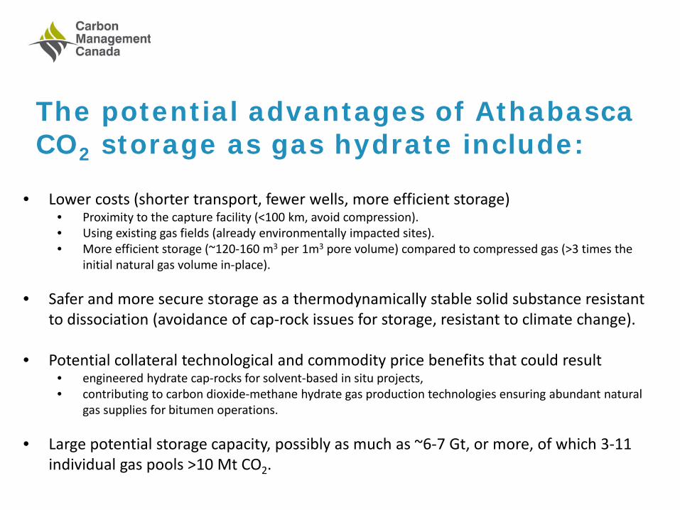
The potential advantages of Athabasca CO2 storage as gas hydrate include:
• Lower costs (shorter transport, fewer wells, more efficient storage) • Proximity to the capture facility (<100 km, avoid compression). • Using existing gas fields (already environmentally impacted sites). • More efficient storage (~120-160 m3 per 1m3 pore volume) compared to compressed gas (>3 times the
initial natural gas volume in-place).
• Safer and more secure storage as a thermodynamically stable solid substance resistant to dissociation (avoidance of cap-rock issues for storage, resistant to climate change).
• Potential collateral technological and commodity price benefits that could result • engineered hydrate cap-rocks for solvent-based in situ projects, • contributing to carbon dioxide-methane hydrate gas production technologies ensuring abundant natural
gas supplies for bitumen operations.
• Large potential storage capacity, possibly as much as ~6-7 Gt, or more, of which 3-11 individual gas pools >10 Mt CO2.

Athabasca CO2 gas hydrate storage in gas pools (Shaw, 2004):
• 18 Athabasca gas pools are in the CO2 gas hydrate stability zone (GHSZ) and 38 more could be promoted to GHSZ @ >p.
• Capacity depends on achievable gas hydrate saturation (Sgh), which is poorly constrained to be 15%-90%.
• Average CO2 storage capacity is 3X IGIP @ 15% Sgh, but 11 X IGIP @ 54% Sgh.
• Depending on Sgh the capacity of 56 candidate gas pools is 79-472 Mt CO2 (284 Mt at 54% Sgh).
• The 10-15 largest gas pools contain 81% to 91% of total storage. capacity.
• There are 3-11 gas pools with individual capacities >10 Mt CO2 if Sgh is 15%-90%.
P-T thresholds for CO2 Hydrate Stability at Different NaCl Concentrations
1.0
1.5
2.0
2.5
3.0
3.5
4.0
4.5
5.0
5.5
6.0
0 1 2 3 4 5 6 7 8 9 10 11 12
Temperature (°C)
Pre
ssu
re (
MP
a)
0 ppt
20 ppt
BOYER BLUESKY E
CHARD WABISKAW I
CHARD MCMURRAY Y
CLYDEN GRAND RAPIDS A
HANGINGSTONE UPPER MANNVILLE D
HANGINGSTONE UPPER MANNVILLE I
HARDY MCMURRAY X
LEISMER CLEARWATER R
LEISMER CLEARWATER DD
LEISMER MCMURRAY L
LEISMER MCMURRAY TTT
LEISMER MCMURRAY UUU
LIEGE UNDESIGNATED
NEWBY MCMURRAY L
NEWBY UNDESIGNATED
PANNY BLUESKY F
RESDELN CLEARWATER G
THORNBURY GRAND RAPIDS A
THORNBURY MCMURRAY K
THORNBURY MCMURRAY XX
POOLS EXCEED P/T BOUNDARY

Gas Pools water-leg associated CO2 gas hydrate storage (Shaw, 2004): • Typically the thickness of the GHSZ is >200 m if the
temperature is > 1-2o C lower than the GHSZ phase.
• Athabasca Mannville gas pool net pays are typically on average individually ~2.5 m thick and average net pay at any location would be ~7.5 m, assuming all three zones are present.
• Athabasca candidate gas pool net pays are 4.1 m net pay and all the candidate gas pools are <10 m thick.
• Most of the GHSZ extends below or on the fringe of
the gas pool.
• Associated gas pool water-leg storage is uncharacterized, but knowledge of it could:
• augment gas pool storage capacity significantly, • change the storage size rank of individual gas pools,
or • it might increase the number of gas pools with >10
Mt CO2 storage capacity.

Aquifer CO2 gas hydrate storage (Cote and Wright, 2013): • Areas of aquifer GHSZ were inferred as a function of
“corrected” surface temperature and geothermal gradient. Not a robust analysis.
• Areas appear to be regionally consistent with GHSZ indications from gas pools and petroleum well data, but high precision temperature logging indicates significant aquifer GHSZ, up to 300 m thick, outside of the regions inferred to have storage potential.
• Cote and Wright (2013) inferred 61 Gt of potential storage in aquifers. This equals Alberta saline aquifer storage capacities. They significantly overestimated the available reservoir thickness and so it is more likely that aquifer storage is 6-7 Gt.
• Even so discounted the majority of storage is in
aquifers not in gas pools.
• A topic for future study as much storage (maybe ~.5 Gt) is available in gas pools proper.

CO2 gas hydrate storage: uncertainties (Sgh is really important)
• We can infer much about the size of the GH storage container, especially considering none of the data were collected with even the remotest though of GH storage.
• The largest uncertainty is the achievable pore space gas hydrate saturation, Sgh. Natural systems reach 90%, but the only available reservoir simulation suggests 15%, using a rudimentary injection technology in a model that did not replicate gas production using known reservoir parameters (i.e. don’t take too much from this model).
• Can we do better? Most probably yes and the recent well tests in Alaska suggest why.
y = 9018x-0.953 R² = 0.751
0.00
5.00
10.00
15.00
20.00
25.00
30.00
35.00
40.00
0 500 1,000 1,500 2,000 2,500
Ratio
of C
O2
volu
me:
IGIP
Initial Pool Pressure (kPa)
Pool Pressure vs. CO2 Storage/IGIP

2011/2012 Ignik Sikumi #1, Alaska • Flow assurance studies provide much
knowledge of hydrate inhibition and promotion using chemical mixtures.
• After 14 days of injecting a mixture of roughly three-quarters nitrogen and one quarter carbon dioxide (as suggested by a Norwegian study) the Ignik Sikumi #1, the produced gas, mainly methane that also contained a higher nitrogen/carbon dioxide ratio than the injected gas.
• Not all of the injected carbon dioxide injected could be produced back indicating that either, primary carbon dioxide hydrate formed in the reservoir, or that carbon dioxide replaced methane in existing hydrate, or both.
• It suggests that the inferred carbon dioxide hydrate is much more stable than methane hydrate and that it is strongly resistant to dissociation.

Current and Future Global Opportunities
1. There is still a significant interest in Asia to improve natural gas production technologies and to understand how these impact territorial claims with respect to strategic natural gas resources and reserves.
2. With a need to find new gas supplies for Inuvik or northern military bases there could be an opportunity for a new Canadian gas hydrate production test or even a demonstration project.
3. CO2 gas hydrate storage for captured oil sands and bitumen gases could be developed as a cost competitive alternative to aquifer storage because of transportation/compression costs and efficiencies of storage.
4. There is a climate friendly, commercial, collaborative technology transfer opportunity for Canadian Industry that can maintain Canadian S&T leadership in a new energy and environmental discipline.