ENDURO SERIES - Yoshimura · 1. Remove the right side cover by removing the two bolts and one...
3
RESEARCH&DEVELOPMENT OF AMERICA, INC. NOTE: IN THE STATE OF CALIFORNIA, IT IS ILLEGAL TO MODIFY THE EMISSION CONTROL SYSTEM, WHICH INCLUDES THE FUEL INJECTION OF ANY VEHICLE. 5420 DANIELS STREET STE A, CHINO CA 91710 · (800) 634-9166 · (909) 628-4722 · FAX (909) 591-2198 CAUTION: The muffler packing on this system MUST be replaced every 6-8 hours of use, or every 1-2 motos. Failure to follow recommended muffler re-packing interval can cause muffler damage and may void the warranty. 221200B250 (CF/SS) RS-2 Stainless Steel Full-System Honda CRF125F Qualified Manufacturer Declared “Replacement Part” 2014~2018 ENDURO SERIES Enduro Series systems are: • Equipped with USFS-approved spark arrestor. • CARB/EPA tail-pipe emissions compliant. • All applications are marked with appropriate EPA noise labels. • Have not been tested for EPA new vehicle noise compliance. www.yoshimura-rd.com
Transcript of ENDURO SERIES - Yoshimura · 1. Remove the right side cover by removing the two bolts and one...

RESEARCH&DEVELOPMENT OF AMERICA, INC.
NOTE: IN THE STATE OF CALIFORNIA, IT IS ILLEGAL TO MODIFY THE EMISSION CONTROL SYSTEM, WHICH INCLUDES THE FUEL INJECTION OF ANY VEHICLE.
5420 DANIELS STREET STE A, CHINO CA 91710 · (800) 634-9166 · (909) 628-4722 · FAX (909) 591-2198
CAUTION: The muffler packing on this system MUST be replaced every 6-8 hours of use, or every 1-2 motos. Failure to follow recommended muffler re-packing interval can cause muffler damage and may void the warranty.
221200B250 (CF/SS)
RS-2 Stainless Steel Full-System
Honda CRF125F
Qualified Manufacturer Declared “Replacement Part”
2014~2018
ENDURO SERIES
Enduro Series systems are:• Equipped with USFS-approved spark arrestor.• CARB/EPA tail-pipe emissions compliant.• All applications are marked with appropriate EPA noise labels. • Have not been tested for EPA new vehicle noise compliance.
www.yoshimura-rd.com

2
Assembly Diagram
No. Item Description Qty.1 22120-101 Yoshimura Header 1
2 221200B250-RMA Yoshimura Muffler 1
3 2115-HS Yoshimura Heatshield 1
4 RC116HSB Heatshield Screws 2
5 RACE-SPS-1 Medium Spring 2
** ST-200 Spring Puller Tool 1
** 347PLUG Yoshimura Wash Plug 1
** 17029 Sticker Kit Sheet 1
5
** Not shown in diagram.
1
2
3
4
5
1. Remove the right side cover by removing the two bolts and one plastic pop rivet located on the inside front of the side cover.
2. Remove the two header nuts.
3. While securely supporting the stock muffler assembly, remove the two muffler mount bolts and carefully remove the stock muffler assembly.
Note: The stock exhaust port gaskets will be re-used. Inspect and replace if necessary.
Removal
Installation
1. Install (No. 1) 22120-101, Yoshimura header using the stock header nuts. Do not torque at this time.
2. Install (No. 2) 221200B250, Yoshimura muffler onto (No. 1) 22120-101, Yoshimura header. Secure muffler to chassis using the stock muffler mount bolt. Torque muffler mount bolt to factory specification.
3. Install (No. 5) RACE-SPS-1, medium exhaust springs onto muffler and header connection.
4. Torque header nuts to factory specification.
5. Install (No. 3) 2115-HS, Yoshimura heatshield onto (No. 1) 22120-101, Yoshimura header using (No. 4) RC116HSB, heatshield screws provided in the kit.
6. Re-install right side cover using the reverse steps of removal.
7. Before starting vehicle, check for proper clearance between new exhaust system and rear suspension (i.e. tire, control arm, brakes, rear shock, and etc.) If any problem is found, please carefully follow through the installation steps again. If problem still persists, please call Yoshimura Tech Department at (800) 634-9166 / in CA (909) 628-4722.
8. It is recommended that the muffler and tailpipe be wiped down with rubbing alcohol to remove oil and fingerprints. This will help prevent tarnishing of the finish after the exhaust is heated up.
Note: After starting vehicle, it is normal for new exhaust system and muffler to emit smoke until oil residue burns off.
3
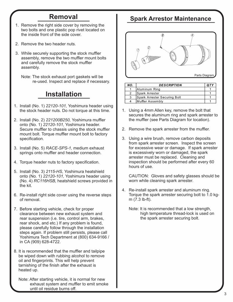
NO. DESCRIPTION QTY
1 Aluminum Ring 1
2 Spark Arrester 1
3 Spark Arrester Securing Bolt 1
4 Muffler Assembly 1
4
1 2
1. Using a 4mm Allen key, remove the bolt that secures the aluminum ring and spark arrester to the muffler (see Parts Diagram for location).
2. Remove the spark arrester from the muffler. 3. Using a wire brush, remove carbon deposits
from spark arrester screen. Inspect the screen for excessive wear or damage. If spark arrester is excessively worn or damaged, the spark arrester must be replaced. Cleaning and inspection should be performed after every 60 hours of use.
CAUTION: Gloves and safety glasses should be worn while cleaning spark arrester.
4. Re-install spark arrester and aluminum ring. Torque the spark arrester securing bolt to 1.0 kg-m (7.3 lb-ft).
Note: It is recommended that a low strength, high temperature thread-lock is used on
the spark arrester securing bolt.
Parts Diagram
Spark Arrestor Maintenance


![INSTALLATION INSTRUCTIONS - Locksmith Security Association1].pdf · INSTALLATION OF THE LOCK 1. Remove the two screws from the lock assembly cover and remove the cover. 2. Remove](https://static.fdocuments.in/doc/165x107/5f50d153ec20231eda26f2b0/installation-instructions-locksmith-security-association-1pdf-installation.jpg)


