
Endpoint Manager for Server Automation - ibm.com · Chapter 1. Overview IBM® Endpoint Manager for...
180
Endpoint Manager for Server Automation
Transcript of Endpoint Manager for Server Automation - ibm.com · Chapter 1. Overview IBM® Endpoint Manager for...
Endpoint Manager for ServerAutomation
���

ii Endpoint Manager for Server Automation
Contents
Chapter 1. Overview . . . . . . . . . 1Supported content . . . . . . . . . . . . 2Architecture . . . . . . . . . . . . . . 5Key features . . . . . . . . . . . . . . 6Server Automation and Data center configuration . . 7Acquiring the Server Automation site . . . . . . 8
Chapter 2. Installation roadmap forServer Automation components . . . . 9Installing the Automation Plan Engine. . . . . . 9
Automation Plan Engine prerequisites . . . . 10Installing the Automation Plan Engine . . . . 11Configuring the Automation Plan Engine . . . 12Specifying the polling interval . . . . . . . 13Specifying the logging level . . . . . . . . 13Upgrading the Automation Plan Engine . . . . 14Upgrading from IBM Endpoint Manager V8.2 . . 14Upgrading from IBM Endpoint Manager V9.0 . . 15Uninstalling the Automation Plan Engine . . . 16
Installing the management extender for VMware . . 17Server Automation domain upgrades . . . . . . 18
Chapter 3. Sequencing actions acrossmultiple endpoints with AutomationPlans . . . . . . . . . . . . . . . 19Introducing Automation Plans and how they work 19Creating an Automation Plan . . . . . . . . 20Creating your Automation Plan. . . . . . . . 21
Defining step failure behavior settings . . . . 26Targeting by computer group . . . . . . . 28Managing pending restart states and automatedrestart of endpoints . . . . . . . . . . . 29Parallel step processing and controlling the flowof your plan . . . . . . . . . . . . . 30Running steps in parallel and settingdependencies between steps . . . . . . . . 31Converting a parallel plan to a sequential plan 33
Automation Plan processing . . . . . . . . . 34Automation Plan Engine shutdown and recovery. . 35Editing an Automation Plan . . . . . . . . . 36Copying an Automation Plan . . . . . . . . 39Deleting an Automation Plan . . . . . . . . 40Running an Automation Plan . . . . . . . . 41Viewing Automation Plan actions . . . . . . . 45Stopping an Automation Plan . . . . . . . . 47Exporting an Automation Plan . . . . . . . . 48Setting or changing the default values of parameters 49
Chapter 4. Virtualization . . . . . . . 51VMware . . . . . . . . . . . . . . . 51
Setup and maintenance . . . . . . . . . 51Virtual server overview . . . . . . . . . 55Host management tasks . . . . . . . . . 56Snapshot management tasks . . . . . . . . 73
Power management tasks. . . . . . . . . 77AIX NIM . . . . . . . . . . . . . . . 81
Setup and Maintenance . . . . . . . . . 81AIX NIM Tasks . . . . . . . . . . . . 85
PowerVM . . . . . . . . . . . . . . . 88Setup and Maintainence . . . . . . . . . 88Managed System Tasks . . . . . . . . . 92LPAR Tasks . . . . . . . . . . . . . 99State Management Tasks. . . . . . . . . 108Sample Automation Plans . . . . . . . . 113
Turning off validation in a Task . . . . . . . 117
Chapter 5. Configuring your systemand best practices . . . . . . . . . 119Overview. . . . . . . . . . . . . . . 119Server Automation components . . . . . . . 120Enhancing the performance of Server Automation 121
Chapter 6. Sample Automation Plans 125Sample Automation Plan for client server patching 125Sample Automation Plan for a physical serverbuild . . . . . . . . . . . . . . . . 126Sample Automation Plan for a virtual server build 127Sample Automation Plan for server patching . . . 129Sample Automation Plan for Windows ClusterPatching 2008-2012 with automated restart ofendpoints . . . . . . . . . . . . . . 130Sample Automation Plan for Windows ClusterPatching 2008-2012 without automated restart ofendpoints . . . . . . . . . . . . . . 132Sample plan Microsoft Exchange 2007 SP1Windows Cluster Patching for Windows 2008-2012with automated reboot . . . . . . . . . . 134Sample plan Microsoft Exchange 2007 SP1Windows Cluster Patching for Windows 2008-2012without automated reboot . . . . . . . . . 136Sample Automation Plan template for deploymentof Oracle Database 11g Enterprise Edition . . . . 138Procedure . . . . . . . . . . . . . . 138Automation template for setting Step FailureThreshold . . . . . . . . . . . . . . 138Automation template for Hyper-V Cluster Patching2008-2012. . . . . . . . . . . . . . . 140Automation template for SQL Server ClusterPatching 2008-2012 . . . . . . . . . . . 141
Chapter 7. Server Automation content 145Patching Microsoft Windows clusters . . . . . 145
Patching Microsoft Windows clusters . . . . 145Patching Servers running Microsoft Exchange2010 and 2013 (Exchange 2013 SP1 and later)Data Availability Groups . . . . . . . . 146Automating patching of operating systemservers in a Microsoft Hyper-V cluster . . . . 148
iii
Patching Microsoft Exchange 2007 on Windowsclusters . . . . . . . . . . . . . . 150Cluster patching terms and concepts . . . . 151
Server Automation middleware content . . . . 152Prerequisites. . . . . . . . . . . . . 152IBM Endpoint Manager for Server Automationmiddleware Tasks . . . . . . . . . . . 154Log file locations . . . . . . . . . . . 164
Server Automation operating system deploymentcontent . . . . . . . . . . . . . . . 164
Example: end-to-end provisioning . . . . . 165How it works . . . . . . . . . . . . 166
Fixlets for operating system deployment . . . 166Server Automation Chef-Solo content . . . . . 168
IBM Endpoint Manager for Server AutomationChef-Solo Tasks . . . . . . . . . . . 168
Server Automation RXA . . . . . . . . . . 169Installing RXA . . . . . . . . . . . . 169
Chapter 8. Notices . . . . . . . . . 171
Index . . . . . . . . . . . . . . . 175
iv Endpoint Manager for Server Automation
Chapter 1. Overview
IBM® Endpoint Manager for Server Automation provides you with the capabilityto automate a sequence of Fixlets, Tasks, and Baselines across different endpoints,such as servers or computers. Server Automation exploits the agility and scalabilityof IBM Endpoint Manager to deliver powerful functionality in a lean and efficientmanner, with minimal impact on your network. Server Automation helps you savetime while maximizing the efficiency of your resources.
Server Automation enables you to run automation tasks in a simple sequence or inparallel across multiple endpoints. You do this by creating an Automation Plan thatcontains a separate step for each action that you want to run across the endpoints.Your Automation Plan can run in a simple straight sequence, where each step isprocessed one after the other, or you can include parallel processing in the plan.For example, you can create an Automation Plan to sequence actions that deployan operating system on a set of virtual servers, then install a database on one ofthose virtual servers while concurrently installing middleware applications on theother virtual servers. You can create sequenced automation that is based onconditions, for example, you might want the Automation Plan to begin only if thevirtual servers are powered on successfully.
To sequence your automation tasks, you create an Automation Plan. EachAutomation Plan contains a number of steps. Each step is a Fixlet, Task, orBaseline and represents an action to be deployed across multiple endpoints, suchas the deployment of a Fixlet to install patches on endpoints.
Some key Server Automation use cases are as follows:
Patch sequencing for endpointsYou can automate patching across multiple endpoints, for example, youcan patch servers.
Patching Microsoft® Windows® clustersYou can also automate patching of applications running on Microsoft®
Windows® clusters. For example, you can use Server Automation Fixlets inan Automation Plan to automate the patching of clusters on whichMicrosoft® SQL Server is installed.
Middleware application installations and deploymentsYou can install, remove, and upgrade middleware applications acrossmultiple endpoints in a single Automation Plan. You can target differentendpoints in different steps in the Automation Plan. Some examples aremulti tier application deployments.
Virtual server managementYou can manage your virtual servers and include virtual servermanagement actions in your Automation Plans.
Example: sequencing automation across endpoints
This example shows typical automation sequencing over a number of servers in adata center. Instead of completing each step manually, you can automate theprocess with an Automation Plan. The Automation Plan contains a number ofsteps, with each step representing a single action, such as the installation ofsoftware or the restarting of a system.
1
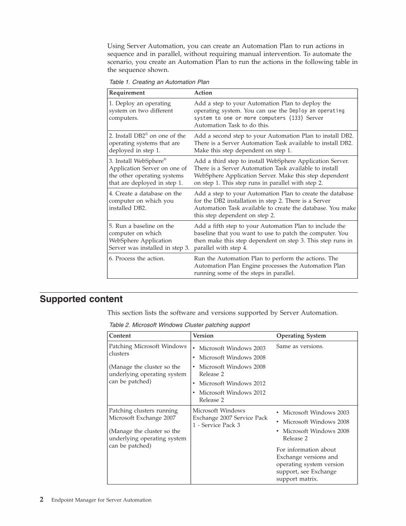
Using Server Automation, you can create an Automation Plan to run actions insequence and in parallel, without requiring manual intervention. To automate thescenario, you create an Automation Plan to run the actions in the following table inthe sequence shown.
Table 1. Creating an Automation Plan
Requirement Action
1. Deploy an operatingsystem on two differentcomputers.
Add a step to your Automation Plan to deploy theoperating system. You can use the Deploy an operatingsystem to one or more computers (133) ServerAutomation Task to do this.
2. Install DB2® on one of theoperating systems that aredeployed in step 1.
Add a second step to your Automation Plan to install DB2.There is a Server Automation Task available to install DB2.Make this step dependent on step 1.
3. Install WebSphere®
Application Server on one ofthe other operating systemsthat are deployed in step 1.
Add a third step to install WebSphere Application Server.There is a Server Automation Task available to installWebSphere Application Server. Make this step dependenton step 1. This step runs in parallel with step 2.
4. Create a database on thecomputer on which youinstalled DB2.
Add a step to your Automation Plan to create the databasefor the DB2 installation in step 2. There is a ServerAutomation Task available to create the database. You makethis step dependent on step 2.
5. Run a baseline on thecomputer on whichWebSphere ApplicationServer was installed in step 3.
Add a fifth step to your Automation Plan to include thebaseline that you want to use to patch the computer. Youthen make this step dependent on step 3. This step runs inparallel with step 4.
6. Process the action. Run the Automation Plan to perform the actions. TheAutomation Plan Engine processes the Automation Planrunning some of the steps in parallel.
Supported contentThis section lists the software and versions supported by Server Automation.
Table 2. Microsoft Windows Cluster patching support
Content Version Operating System
Patching Microsoft Windowsclusters
(Manage the cluster so theunderlying operating systemcan be patched)
v Microsoft Windows 2003
v Microsoft Windows 2008
v Microsoft Windows 2008Release 2
v Microsoft Windows 2012
v Microsoft Windows 2012Release 2
Same as versions.
Patching clusters runningMicrosoft Exchange 2007
(Manage the cluster so theunderlying operating systemcan be patched)
Microsoft WindowsExchange 2007 Service Pack1 - Service Pack 3
v Microsoft Windows 2003
v Microsoft Windows 2008
v Microsoft Windows 2008Release 2
For information aboutExchange versions andoperating system versionsupport, see Exchangesupport matrix.
2 Endpoint Manager for Server Automation
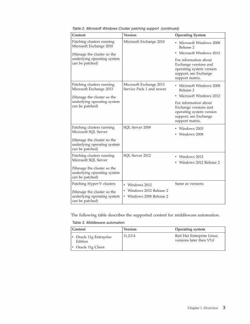
Table 2. Microsoft Windows Cluster patching support (continued)
Content Version Operating System
Patching clusters runningMicrosoft Exchange 2010
(Manage the cluster so theunderlying operating systemcan be patched)
Microsoft Exchange 2010 v Microsoft Windows 2008Release 2
v Microsoft Windows 2012
For information aboutExchange versions andoperating system versionsupport, see Exchangesupport matrix.
Patching clusters runningMicrosoft Exchange 2013
(Manage the cluster so theunderlying operating systemcan be patched)
Microsoft Exchange 2013Service Pack 1 and newer
v Microsoft Windows 2008Release 2
v Microsoft Windows 2012
For information aboutExchange versions andoperating system versionsupport, see Exchangesupport matrix.
Patching clusters runningMicrosoft SQL Server
(Manage the cluster so theunderlying operating systemcan be patched)
SQL Server 2008 v Windows 2003
v Windows 2008
Patching clusters runningMicrosoft SQL Server
(Manage the cluster so theunderlying operating systemcan be patched)
SQL Server 2012 v Windows 2012
v Windows 2012 Release 2
Patching Hyper-V clusters
(Manage the cluster so theunderlying operating systemcan be patched)
v Windows 2012
v Windows 2012 Release 2
v Windows 2008 Release 2
Same as versions.
The following table describes the supported content for middleware automation.
Table 3. Middleware automation
Content Version Operating system
v Oracle 11g EnterpriseEdition
v Oracle 11g Client
11.2.0.4 Red Hat Enterprise Linuxversions later then V5.0
Chapter 1. Overview 3
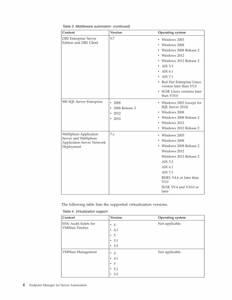
Table 3. Middleware automation (continued)
Content Version Operating system
DB2 Enterprise ServerEdition and DB2 Client
9.7 v Windows 2003
v Windows 2008
v Windows 2008 Release 2
v Windows 2012
v Windows 2012 Release 2
v AIX 5.3
v AIX 6.1
v AIX 7.1
v Red Hat Enterprise Linuxversion later than V5.0
v SUSE Linux versions laterthan V10.0
MS SQL Server Enterprise v 2008
v 2008 Release 2
v 2012
v 2014
v Windows 2003 (except forSQL Server 2014)
v Windows 2008
v Windows 2008 Release 2
v Windows 2012
v Windows 2012 Release 2
WebSphere ApplicationServer and WebSphereApplication Server NetworkDeployment
7.x v Windows 2003
v Windows 2008
v Windows 2008 Release 2
Windows 2012
Windows 2012 Release 2
AIX 5.3
AIX 6.1
AIX 7.1
RHEL V4.6 or later thanV5.0
SUSE V9.4 and V10.0 orlater
The following table lists the supported virtualization versions.
Table 4. Virtualization support
Content Version Operating system
ESXi Audit fixlets forVMWare Patches
v 4
v 4.1
v 5
v 5.1
v 5.5
Not applicable.
VMWare Management v 4
v 4.1
v 5
v 5.1
v 5.5
Not applicable.
4 Endpoint Manager for Server Automation
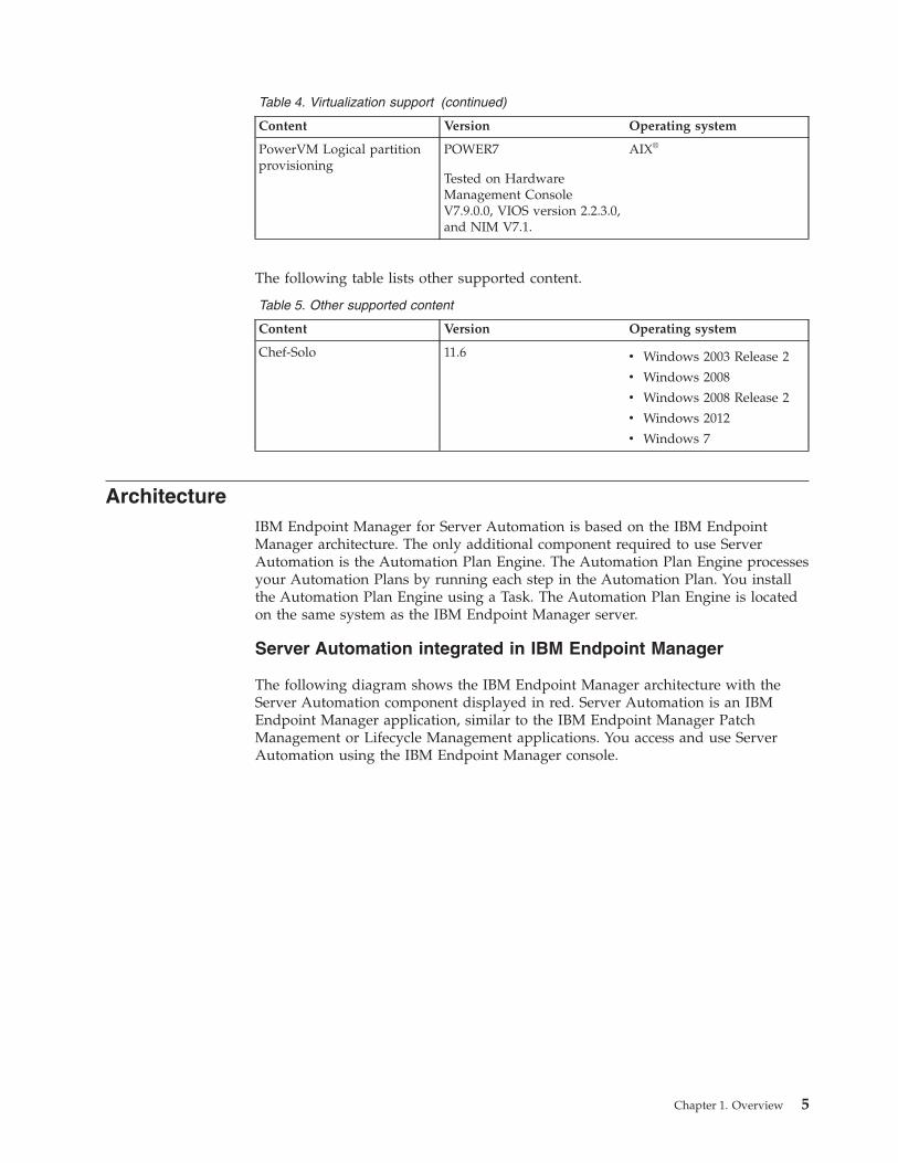
Table 4. Virtualization support (continued)
Content Version Operating system
PowerVM Logical partitionprovisioning
POWER7
Tested on HardwareManagement ConsoleV7.9.0.0, VIOS version 2.2.3.0,and NIM V7.1.
AIX®
The following table lists other supported content.
Table 5. Other supported content
Content Version Operating system
Chef-Solo 11.6 v Windows 2003 Release 2
v Windows 2008
v Windows 2008 Release 2
v Windows 2012
v Windows 7
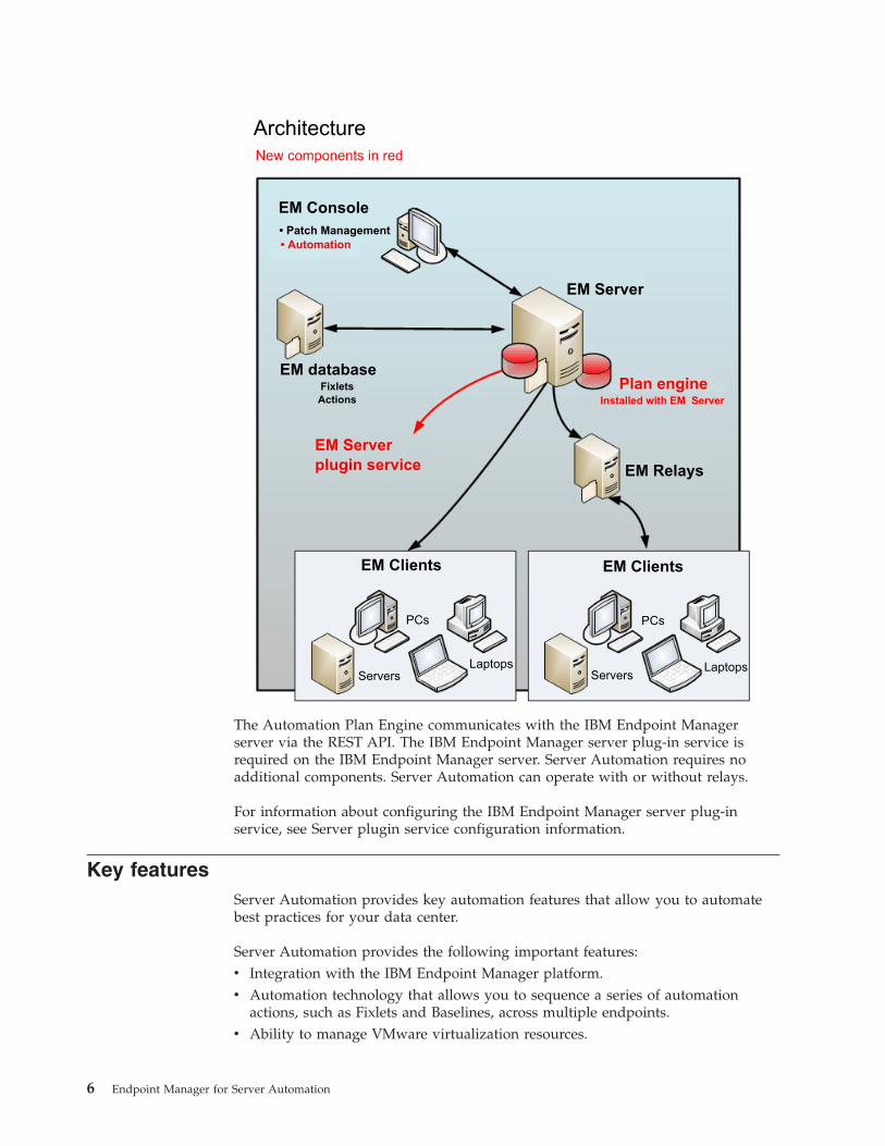
ArchitectureIBM Endpoint Manager for Server Automation is based on the IBM EndpointManager architecture. The only additional component required to use ServerAutomation is the Automation Plan Engine. The Automation Plan Engine processesyour Automation Plans by running each step in the Automation Plan. You installthe Automation Plan Engine using a Task. The Automation Plan Engine is locatedon the same system as the IBM Endpoint Manager server.
Server Automation integrated in IBM Endpoint Manager
The following diagram shows the IBM Endpoint Manager architecture with theServer Automation component displayed in red. Server Automation is an IBMEndpoint Manager application, similar to the IBM Endpoint Manager PatchManagement or Lifecycle Management applications. You access and use ServerAutomation using the IBM Endpoint Manager console.
Chapter 1. Overview 5
ArchitectureNew components in red
EM Console• Patch Management• Automation
EM Server
Plan engineInstalled with EM Server
EM RelaysEM Server plugin service
EM databaseFixletsActions
PCs
ServersLaptops
EM Clients
PCs
ServersLaptops
EM Clients
The Automation Plan Engine communicates with the IBM Endpoint Managerserver via the REST API. The IBM Endpoint Manager server plug-in service isrequired on the IBM Endpoint Manager server. Server Automation requires noadditional components. Server Automation can operate with or without relays.
For information about configuring the IBM Endpoint Manager server plug-inservice, see Server plugin service configuration information.
Key featuresServer Automation provides key automation features that allow you to automatebest practices for your data center.
Server Automation provides the following important features:v Integration with the IBM Endpoint Manager platform.v Automation technology that allows you to sequence a series of automation
actions, such as Fixlets and Baselines, across multiple endpoints.v Ability to manage VMware virtualization resources.
6 Endpoint Manager for Server Automation
v Middleware content that you can use to automate deployment of middlewareapplications.
v Fixlet content for automating the patching process for Microsoft® Windows®
clusters.v Fixlet content for automating deployment of operating systems.v Preconfigured Fixlets that allow you to deploy operating systems as part of your
Automation Plans.
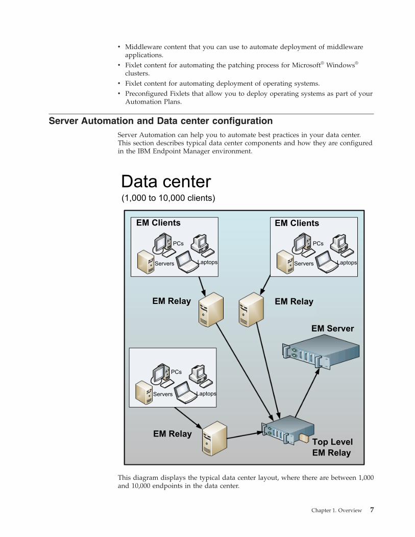
Server Automation and Data center configurationServer Automation can help you to automate best practices in your data center.This section describes typical data center components and how they are configuredin the IBM Endpoint Manager environment.
Data center(1,000 to 10,000 clients)
EM Clients EM Clients
PCs PCs
Servers ServersLaptops Laptops
EM Relay EM Relay
EM Server
PCs
Servers Laptops
EM RelayTop LevelEM Relay
This diagram displays the typical data center layout, where there are between 1,000and 10,000 endpoints in the data center.
Chapter 1. Overview 7
A typical data center is made up of between 1,000 and 10,000 endpoints, many ofwhich are servers. In a topology such as this, you can use a top level IBMEndpoint Manager relay that communicates directly with the IBM EndpointManager server. Lower level relays communicate with the IBM Endpoint Managerserver through the top level relay. For detailed information about configurationand best practice recommendations for using relays, see TEM Relays.
Acquiring the Server Automation siteAfter installing IBM Endpoint Manager, you can access the Server Automation site.You can only access the Server Automation site if you have purchased the license.
About this task
Ensure that you have signed off on the license agreement. The license agreementmust be signed off before you can get the contents of the Server Automation site.
Complete the following steps to access the Server Automation site.
Procedure1. From your IBM Endpoint Manager console, go to the BigFix Management
domain and click License Overview.2. Go to the Server Automation section of the License Overview Dashboard and
accept the Endpoint Manager for Server Automation license.
Note: You might need to click the Check for license update button.3. Click Enable beside the Server Automation site. The Server Automation site is
made available on your console. It might take some time for the contents tobecome available on your system.
8 Endpoint Manager for Server Automation
Chapter 2. Installation roadmap for Server Automationcomponents
To use IBM Endpoint Manager for Server Automation, you must install theAutomation Plan Engine. To use the virtualization technology, you must installmanagement extenders. The installation roadmap for Server Automation describeseach of the steps that you must perform to get Server Automation up and running.
The following steps show the installation roadmap for IBM Endpoint Manager forServer Automation:v Install IBM Endpoint Manager version 9.1.v Before you can install the Server Automation components, you must acquire the
Server Automation license and site. For information about how to acquire theServer Automation site, see “Acquiring the Server Automation site” on page 8.
v Install the Automation Plan Engine, using the “Installing the Automation PlanEngine” documentation. The Automation Plan Engine processes yourAutomation Plans.
v Install the management extender for virtualization, using “Installing themanagement extender for VMware” on page 17. The management extenderenables communication with the VMware vCenter.
For information about how to install IBM Endpoint Manager, see Installing IBMEndpoint Manager on Windows and Installing IBM Endpoint Manager on Linux.
For information about how to install the IBM Endpoint Manager client, seeInstalling the client on Windows and Installing the client on Linux.
Installing the Automation Plan EngineTo install the Automation Plan Engine, you must have IBM Endpoint ManagerV9.1 or later with the Server Automation site installed. Make sure that your systemmeets all of the prerequisites before you begin installing the Automation PlanEngine. You can then install the Automation Plan Engine by executing a Task fromyour IBM Endpoint Manager console.
Install the Automation Plan Engine by completing the following steps:1. Read the documentation for important information about the installation.2. Complete the prerequisites. After you have completed the prerequisites, you are
ready to install the Automation Plan Engine and the Task that installs theAutomation Plan Engine becomes relevant.
3. Run the Task that installs the Automation Plan Engine on the IBM EndpointManager server. The installation takes a few minutes and when it hascompleted, the Task that installs the Automation Plan Engine is no longerrelevant.
4. Verify that the Automation Plan Engine installed successfully and has started.The IBM Endpoint Manager server plugin service starts the Automation PlanEngine when it is installed on the IBM Endpoint Manager server.
The following sections describe each of these steps in detail.
© International Business Machines Corporation 2012 9
Automation Plan Engine prerequisitesYou can install the Automation Plan Engine on Linux and Windows platforms.Before installing the Automation Plan Engine, make sure that your system meetsall of the prerequisites. This section describes all of the prerequisite tasks that youmust complete before installing the Automation Plan Engine and the instructionsare the same for both Windows and Linux.
About this task
Before you begin completing the prerequisite tasks, make sure that the externalcontent site, BES Support, is accessible. This site publishes the Tasks to install therequired component, the IBM Endpoint Manager server plugin service.
Note: The BES Server Plug-in Service, displayed on the user interface, is asynonym for the IBM Endpoint Manager server plugin service. The IBM EndpointManager server plugin service is the new term.
For each of the Fixlets or Tasks described here, there is normally a lag between thetime you run one Fixlet or Task and when another becomes relevant and available.
Complete the following prerequisite steps in the order in which Tasks or Fixletsbecome relevant in the Server Automation domain. The Tasks or Fixlets onlybecome relevant after you complete a dependant step.
Procedure1. You must have IBM Endpoint Manager V9.1 installed to install the Automation
Plan Engine. For a Linux installation, the IBM Endpoint Manager console mustbe installed on a Windows system.
2. You must have Web Reports installed with your IBM Endpoint Managerinstallation, and create a user with normal access rights in Web Reports. Youmust do this in Web Reports and this is a different user than the users that youcreate in the IBM Endpoint Manager console. For more information aboutcreating a user in Web Reports, see Web Reports User's Guide.
3. Create a new IBM Endpoint Manager console user for the installation withmaster operator privileges. Do not use any unsupported characters in the username or password for the Web Reports user. For information about theunsupported characters, see Unsupported user name and password characters.
4. Ensure that the site for the Automation domain, called Server Automation, isaccessible. This site publishes the Task that installs the Automation PlanEngine.
5. Your computers must be subscribed to the Server Automation site. To subscribethe computers, select the Server Automation site from the Sites > External Sitessection in the All Content domain. Click the Computer Subscriptions tab andsubscribe the computers that you want to have access to the Server Automationsite.
6. Install the IBM Endpoint Manager server plugin service on the IBM EndpointManager server. Install this plug-in using the Install BES Server PluginService Task from Setup and Maintenance > Fixlets and Tasks in theAutomation node. When you click Take Action, target the IBM EndpointManager server.
7. Enable encryption of the credentials for the IBM Endpoint Manager REST APIby running the Configure REST API credentials for BES Server PluginService Task from Setup and Maintenance > Fixlets and Tasks in theAutomation node:
10 Endpoint Manager for Server Automation
a. Click the Configure REST API credentials for BES Server Plugin ServiceTask. The user interface from which you must start the encryptionenablement Task is displayed.
b. Enter the user name and password for the master operator user you createdin step 3. This creates an encrypted password.
c. Click Take Action and specify the server where you are installing theAutomation Plan Engine, which is the IBM Endpoint Manager server.
Note: The Configure REST API credentials for BES Server PluginService Task remains relevant after you run it. You can check the actionhistory to confirm that it has run.
Results
After completing all of the steps described in this topic, the Task to install theAutomation Plan Engine becomes relevant. You can now proceed to install theAutomation Plan Engine.
Installing the Automation Plan EngineYou can install the Automation Plan Engine on Windows and Linux systems. Toinstall the Automation Plan Engine, you run a Task from your IBM EndpointManager console. The Task to install the Automation Plan Engine becomes relevantonly if the IBM Endpoint Manager server plugin service is installed correctly. Youmust install the Automation Plan Engine on the system on which the IBMEndpoint Manager server is installed. The installation procedure is the same forboth Windows and Linux.
About this task
Before you begin installing the Automation Plan Engine, make sure that yoursystem meets the prerequisites as described in Automation Plan engineprerequisites. There is one Task for installing and upgrading the Automation PlanEngine and another Task for uninstalling the Automation Plan Engine. Each ofthese Tasks becomes relevant depending on whether you already installed theAutomation Plan Engine. When you install the Automation Plan Engine, the Taskthat installs it becomes non-relevant and the Task that uninstalls it becomesrelevant. After you install the Automation Plan Engine, it can take a few minutesfor the Automation Plan Engine installation Task to become non-relevant.
Complete the following steps to install the Automation Plan Engine.
Procedure1. Log on to the IBM Endpoint Manager console as the master operator and
navigate to the Server Automation domain. Note for a Linux installation, theconsole must be installed on Windows.
2. From the Automation node, click Setup and Maintenance > Fixlets and Tasksand select one of the following Tasks, depending on your platform:v For Windows platforms, select the Install Latest Automation Plan Engine.v For Linux platforms, select the Install Latest Automation Plan Engine
(RHEL).3. Click Take Action.4. From the Take Action dialog box, target the system on which the IBM
Endpoint Manager server is installed.
Chapter 2. Installing Server Automation components 11
5. Click OK. The Task runs and installs the Automation Plan Engine. The defaultlocation for the Automation Plan Engine installation is in the followingdirectory:v For Windows platforms, the C:\Program Files (x86)\BigFix Enterprise\BES
Server\Applications\PlanEngine directory.v For Linux platforms, the /var/opt/BESServer/Applications/PlanEngine
directory.
It can take a few minutes for the Automation Plan Engine installation Task tobecome non-relevant. The uninstallation Task now becomes relevant.
Results
After the Automation Plan Engine is installed, the IBM Endpoint Manager serverplugin service starts it automatically. The Automation Plan Engine log file,pe_console.log, is available in the following location, depending on your platform:v For Windows, the pe_console.log log file is available in the \BES
Server\Applications\Logs subdirectory of the installation directory, for example,C:\Program Files (x86)\BigFix Enterprise\BES Server\Applications\Logsdirectory.
v For an installation with default values on Linux, the pe_console.log log file isavailable in the /var/opt/BESServer/Applications/Logs directory.
To verify that the Automation Plan Engine is installed correctly and has started,check for the following lines at the start of the log file:2013-08-23 13:15:20,235 INFO [main] (cli.PlanEngineLauncher:255) :: IZNENG025I \Plan Engine (build number 0.49) starting in JVM with PID (4508) ...2013-08-23 13:15:20,235 INFO [main] (cli.PlanEngineLauncher:259) :: IZNENG026I \Plan Engine CLI initializing ...2013-08-23 13:15:20,235 INFO [main] (cli.PlanEngineLauncher:130) :: IZNENG001I \Received command: "start"
Troubleshooting the Automation Plan Engine installationIf you have trouble completing the Automation Plan Engine installation,troubleshooting Tasks become relevant to help you to correct the problems. TheseTasks only become relevant if you need to run them.
Troubleshooting Tasks become relevant in a Warnings folder if you experienceproblems installing the Automation Plan Engine. If you have problems installingthe Automation Plan Engine, look for the Warnings folder. If this folder displays,check this folder to see which Tasks are relevant. To correct the problems with theinstallation, run any Tasks that are relevant.
If you do not see any relevant Tasks or the Warnings folder, your system isconfigured correctly for the installation.
Configuring the Automation Plan EngineYou can modify the configuration of the Automation Plan Engine. The config.xmlconfiguration file contains properties that you can use to control the AutomationPlan Engine behavior.
The config.xml file contains the following properties:v The Polling interval for open Automation Plan actions is pe.update.interval.
The Automation Plan Engine queries the IBM Endpoint Manager server to findopen Automation Plan actions to process. When the most recently retrieved set
12 Endpoint Manager for Server Automation
of open Automation Plan actions are processed, the Automation Plan Enginewaits for the time that is specified in the polling interval before querying again.
v The Numeric argument conversion property isnumeric.argument.conversion.enabled. This property is an internal AutomationPlan Engine property. Do not change the value of this property.
Specifying the polling intervalTo modify the polling interval, edit the pe.update.interval value in theconfig.xml file.
About this task
The default value for the poling interval, pe.update.interval, is 3,000milliseconds. If the value of the property in config.xml is missing or invalid, theAutomation Plan Engine uses the default value.
If you change the pe.update.interval, the change is applied without restarting theAutomation Plan Engine.
Procedure1. Open the config.xml file in a text editor. On Linux, the config.xml file is
located in the /var/opt/BESServer/Applications/PlanEngine/config directory.On Windows, locate the config.xml file, as follows:a. Open the Windows registry by running regedit from an MS DOS prompt.b. Search for the HKEY_LOCAL_MACHINE\SOFTWARE\Wow6432Node\BigFix\
Enterprise Server key.c. Find the EnterpriseServerFolder value in the appropriate key.d. To change the contents of the config.xml file, open the Automation Plan
Engine installation directory that is specified in the EnterpriseServerFoldervalue. Open the Applications\PlanEngine\config subdirectory of theinstallation directory. Open the config.xml file in a text editor.
2. Change the pe.update.interval value to the value of the polling interval.3. Save and close the config.xml file.
Specifying the logging levelYou can change the Automation Plan Engine logging level without stopping andrestarting the Automation Plan Engine. For Windows, the Automation Plan Enginelog file, pe_console.log, is located in the \BES Server\Applications\Logssubdirectory of the installation directory, for example, C:\Program Files(x86)\BigFix Enterprise\BES Server\Applications\Logs. For Linux, thepe_console.log file is located in the /var/opt/BESServer/Applications/Logsdirectory.
About this task
You can change the logging level of the Automation Plan Engine to differentlogging configurations. By default, Automation Plan Engine logs informationmessages, warnings, and errors. You can set the Automation Plan Engine logginglevel to DEBUG to log more detailed information about the internal operations of theAutomation Plan Engine.
You can change the logging level by editing the log4j.prop file.
Chapter 2. Installing Server Automation components 13
Note: Do not uncomment to enable any of the entries in the Local Settings sectionof the log4j.prop file. If you enable any of these settings by uncommenting them,you might encounter errors.
Procedure1. Open the log4j.prop file. On Linux, the log4j.prop file is located in the
/var/opt/BESServer/Applications/PlanEngine/config directory. On Windows,locate the log4j.prop file, as follows:a. Open the Windows registry by running regedit from an MS DOS prompt.b. Search for the HKEY_LOCAL_MACHINE\SOFTWARE\Wow6432Node\BigFix\
Enterprise Server key.c. Find the EnterpriseServerFolder value in the key.d. To change the contents of the log4j.prop file, open the Automation Plan
Engine installation directory that is specified in the EnterpriseServerFoldervalue. Open the BES Server\Applications\PlanEngine\config subdirectoryof the installation directory. Open the log4j.prop file in a text editor.
2. To change the logging level, edit the log4j.prop file, specifying the logginglevel you want. For example, to change the logging level to debug, changelog4j.appender.console.threshold=INFO tolog4j.appender.console.threshold=DEBUG andlog4j.appender.consolefile.threshold=INFO tolog4j.appender.consolefile.threshold=DEBUG. Valid thresholds include TRACE,DEBUG, INFO, WARN, ERROR, and FATAL.
3. Save and close the log4j.prop file.
Results
The Automation Plan Engine automatically includes the logging level changewithout requiring you to restart the system.
Upgrading the Automation Plan EngineTo upgrade the Automation Plan Engine, you run a Task from your IBM EndpointManager console. There are two upgrade scenarios described here. Use the firstprocedure if you upgraded your version of IBM Endpoint Manager from V8.2 toV9.1 and want to upgrade the Automation Plan Engine. Use the second scenario ifyou upgraded IBM Endpoint Manager V9.0 to V9.1 and want to upgrade theAutomation Plan Engine. The procedure is the same for Microsoft Windows andLinux upgrades, except where identified as platform specific.
Upgrading from IBM Endpoint Manager V8.2If you previously had Server Automation running on IBM Endpoint Manager V8.2and upgraded your IBM Endpoint Manager system to V9.1, complete the followingsteps to upgrade the Automation Plan Engine.
Procedure1. After upgrading IBM Endpoint Manager to V9.1, check that your version of the
BES Server Plugin Service is V2.0.0.0 or later. If necessary, update the BESServer Plugin Service. To check your version of the BES Server PluginService:v On Microsoft Windows systems, the BES Server Plugin Service executable
is the MFS.exe file in the C:\Program Files (x86)\BigFix Enterprise\BESServer\Applications directory. Right click the MFS.exe file and selectProperties and then the Details tab to check the version number.
14 Endpoint Manager for Server Automation
v On Linux systems, the BES Server Plugin Service executable is the MFSexecutable file in the /var/opt/BESServer/Applications directory. TheMFS-Linux.ver file contains the MFS version. Use the cat MFS-Linux.vercommand to display the version.
2. After upgrading IBM Endpoint Manager to V9.1, the Configure REST APIcredentials for BES Server Plugin Service Task becomes relevant. Run thisTask, targeting the IBM Endpoint Manager server:a. Log on to the IBM Endpoint Manager console as the master operator and
go to the Server Automation domain.b. From the Automation node, click Setup and Maintenance and select the
Configure REST API credentials for BES Server Plugin Service Task.c. Enter the master operator credentials on the Description section and click
Take Action.d. From the Take Action dialog box, target the system on which the IBM
Endpoint Manager server is installed.
A short time later, the Install Latest Automation Plan Engine Task becomesrelevant.
3. Run the Install Latest Automation Plan Engine Task targeting the IBMEndpoint Manager server. The latest version of the Automation Plan Engine isinstalled in the BES Server\Applications\PlanEngine subdirectory of theinstallation directory.
Upgrading from IBM Endpoint Manager V9.0If you upgraded IBM Endpoint Manager from V9.0 to V9.1, use the InstallLatest Automation Plan Engine Task to upgrade the Automation Plan Engine. Youuse the same Task to install the Automation Plan Engine. When the AutomationPlan Engine is installed, the Install Latest Automation Plan Engine Task isrelevant if the version of the Automation Plan Engine that is installed is earlierthan the version in the Task.
About this task
Before an upgrade, the Install Latest Automation Plan Engine Task shuts downthe Automation Plan Engine and removes it.
Note: The Install Latest Automation Plan Engine Task cannot fully remove anexisting Automation Plan Engine instance if the files in the BESServer\Applications\PlanEngine subdirectory of the installation directory arebeing accessed by another user or application. To ensure that the Install LatestAutomation Plan Engine Task runs successfully, you must close all otherapplications that access this directory before you run the Task.
Complete the following steps to upgrade the Automation Plan Engine.
Procedure1. Log on to the IBM Endpoint Manager console as the master operator and go to
the Server Automation domain.2. From the Automation node, click Setup and Maintenance and select the Install
Latest Automation Plan Engine Task.3. Click Take Action.4. From the Take Action dialog box, target the system on which the IBM
Endpoint Manager server is installed.
Chapter 2. Installing Server Automation components 15
5. Click OK. The latest version of the Automation Plan Engine is installed in theBES Server\Applications\PlanEngine subdirectory of the installation directory.
Results
The latest version of the Automation Plan Engine is installed. The IBM EndpointManager server plugin service restarts the Automation Plan Engine automatically.The Automation Plan Engine resumes processing any Automation Plan actions andstep actions that were running before the upgrade. All the configuration data inthe config.xml file and the log4j.prop file is unchanged by the upgrade. Theversion of the Automation Plan Engine installed by the Install Latest AutomationPlan Engine Task is logged in the pe_console.log file in the \BESServer\Applications\Logs subdirectory of the installation directory.
Note: Do not uncomment to enable any of the entries in the Local Settings sectionof the log4j.prop file in the BES Server\Applications\PlanEngine\config folder. Ifyou enable any of these settings by uncommenting them, you might encountererrors.
Uninstalling the Automation Plan EngineTo uninstall the Automation Plan Engine, you run a Task from your IBM EndpointManager console. The Task to uninstall the Automation Plan Engine becomesrelevant when you install the Automation Plan Engine.
About this task
There is one Task to install the Automation Plan Engine and another Task touninstall the Automation Plan Engine. When you install the Automation PlanEngine, the Task to install becomes non-relevant and the Task to uninstall becomesrelevant.
Complete the following steps to uninstall the Automation Plan Engine.
Procedure1. Log on to the IBM Endpoint Manager console as the master operator and go to
the Server Automation domain.2. From the Automation node, click Setup and Maintenance > Fixlets and Tasks
and select one of the following Tasks, depending on your platform:v For Windows, select the Uninstall Automation Plan Engine Task.v For Linux, select the Uninstall Automation Plan Engine (RHEL) Task.
3. Click Take Action.4. From the Take Action dialog box, target the system on which the IBM
Endpoint Manager server is installed.5. Click OK. After uninstallation, the Automation Plan Engine installation Task
becomes relevant. The uninstallation Task becomes non-relevant.
Results
The Uninstall Automation Plan Engine Task runs and uninstalls the AutomationPlan Engine.
Troubleshooting the uninstallationYou can use the information about troubleshooting errors in uninstalling theAutomation Plan Engine if your uninstallation is unsuccessful.
16 Endpoint Manager for Server Automation
There are several ways an Automation Plan Engine uninstallation might fail. Foreach type of failure, there are one or more potential causes and one or moresolutions.
The Uninstall Automation Plan Engine Task fails
The uninstallation Task might fail to complete successfully if it cannot remove filesfrom the file system because they are in use.
If this happens, shut down any applications that are using the files that cannot beremoved and run the Uninstall Automation Plan Engine Task again. TheUninstall Automation Plan Engine Task remains relevant until it has beencompleted successfully.
The Install Latest Automation Plan Engine Task does not becomerelevant as soon as the Uninstall Automation Plan Engine Task iscomplete
This is normal. There is a time lag because of the frequency of the Task relevanceevaluation.
Installing the management extender for VMwareBefore you work with IBM Endpoint Manager for Server Automation virtualizationfeatures, you must install a management extender to communicate with theVMware vCenter or ESX host. Before you install the management extender, youmust enable the license for Virtual Endpoint Manager.
Before you begin
You must have a relay server or a root server Version 9.0 or later. A VMwaremanagement extender must not be already installed on the server. Because of theworkload that is imposed on the system by the management extender, it isrecommended that you install the management extender on a relay server and nota root server.
Important: You must ensure that the license for Virtual Endpoint Manager isenabled. To enable the Virtual Endpoint Manager license, go to the BigfixManagement domain, navigate to License Overview > Lifecycle Management.From the list of Available Sites, enable Virtual Endpoint Manager. When VirtualEndpoint Manager is enabled, it disappears from the Available Sites list and isdisplayed in the Enabled Sites list.
Procedure1. Open the Server Automation domain.2. From the navigation tree in the Server Automation domain, click Virtualization
> Setup and Maintainance > Deploy VMware Components.3. In the Deploy VMware Components window, select the Deploy Management
Extender for VMware vCenter Task.4. In the Task: Deploy Management Extender for VMware vCenter window,
click Take Action.5. In the Take Action dialog box, ensure Specific computers selected in the list
below is selected.6. In the Computer Name list, select a relay server or a root server and click OK.
Chapter 2. Installing Server Automation components 17
Results
In the Action: Deploy Management Extender for VMware vCenter window, youcan check the status of the installation. When the status changes to Completed, themanagement extender for VMware is installed.
What to do next
After you install the management extender for VMware, you must configure themanagement extender with your VMware system details. For more informationabout configuring the management extender, see “Configuring managementextenders” on page 52.
Server Automation domain upgradesThe Server Automation domain is upgraded automatically when the contents ofthe Server Automation site is updated.
When you acquire the Server Automation site, the Server Automation domain isalso added to your IBM Endpoint Manager console. The procedure to acquire theServer Automation site is described in Acquiring the IBM Endpoint Manager forServer Automation site.
After you acquire the Server Automation site, all updated site content is gatheredautomatically. When Server Automation domain updates are available, they areautomatically updated in your IBM Endpoint Manager console.
18 Endpoint Manager for Server Automation
Chapter 3. Sequencing actions across multiple endpoints withAutomation Plans
IBM Endpoint Manager for Server Automation provides you with technology tosequence actions, such as the deployment of Fixlets, across multiple endpoints. Tosequence automation, you create an Automation Plan. Your Automation Plancontains all of the actions for your end-to-end automation sequence.
Automation Plans can run a sequence of Fixlets, Tasks, and Baselines acrossmultiple endpoints, with steps running in parallel. You can target differentendpoints for each step in your Automation Plan.
Introducing Automation Plans and how they workYou can create Automation Plans that run multiple Fixlets, Tasks, or Baselines on aset of endpoints that you specify. Each Fixlet, Task, or Baseline can run on adifferent set of endpoints. You can use the Automation Plan Editor to create, edit,copy, and delete Automation Plans. You must run Automation Plans in theAutomation Plans dashboard in the Server Automation domain. When you createyour Automation Plans, you can set and save a set of default endpoints, defaultparameters, and filters for each step in the Automation Plan. This increases theease-of-use and facilitates faster reuse of Automation Plans.
An Automation Plan is a grouping of Tasks, Fixlets, and Baselines called steps,performed on a set of endpoints in a sequence that you specify. Each step in anAutomation Plan represents a single Fixlet, Task, or Baseline and each step can betargeted at different endpoints. A single command deploys or schedules thesequence of steps across a set of endpoints that you specify, in the order in whichthey are displayed in the Automation Plan Editor. When a step completessuccessfully, the step action state is set to stopped and the next step in theAutomation Plan is run. When the final step in the Automation Plan completes, theAutomation Plan action state is set to stopped.
You can schedule an Automation Plan to run at a specified date or time. When youschedule an Automation Plan to run at a future date or time, the Automation Planaction is created, and remains in an open state until the Automation Plan Enginestarts to run the action at the time and date that you specified.
If you are scheduling your Automation Plan, you can opt to prefetch the contentthat needs to be downloaded. This option allows you to download the contentrequired as part of the Automation Plan in advance of the execution of theAutomation Plan. This speeds up the execution of the Automation Plan so thatwhen the Automation Plan runs, the content has been downloaded in advance andruns much faster than if you do not choose this option. To use this option, youselect the Prefetch downloads check box when you are scheduling yourAutomation Plan. If you select this option, an open action is created for each stepin your Automation Plan. You can view these actions from the Automation PlanAction Status dashboard.
For each step in your Automation Plan, you can target computer groups as well asindividual computers. You can do this by saving default targets when creatingyour Automation Plan, or at runtime, when you are running your AutomationPlan.
© International Business Machines Corporation 2012 19
All Automation Plans that are created in the Server Automation domain aredisplayed as Fixlets in the Fixlets and Tasks list in the All Content domain. If yourun or schedule an Automation Plan in the Fixlets and Tasks panel, it will fail. Ifyou add an Automation Plan as a Component in a Baseline, it will fail. You mustrun or schedule an Automation Plan in only the Automation Plans dashboard inthe Server Automation domain.
When you add a step to an Automation Plan, you are adding a Fixlet, Task, orBaseline to the Automation Plan. A copy of the Fixlet, Task, or Baseline is stored inthe Automation Plan. If this source content changes after it is added to theAutomation Plan, the changes are not reflected in the copy in the Automation Plan.If the source Fixlet, Task, or Baseline changes, the Automation Plan displays anicon indicating that the copy in your Automation Plan no longer matches thesource. You can then update the copy in the Automation Plan with the latestversion of the source if you have access to the source. For legacy AutomationPlans, this notification is displayed only if you edit and save the plan. AutomationPlans created before Server Automation application update 3.0 do notautomatically display that source content is out of date.
Each step in an Automation Plan has one action. A Fixlet or Task that you add tothe step can have multiple actions. When you use the Automation Plan Editor toadd a Fixlet or Task with multiple actions to a step, you must choose one actionfrom the list of available actions. If you add a Fixlet or Task with a default action,the Automation Plan Editor automatically adds this action to the step. If you add aFixlet or Task with an action that has a script type of URL, you cannot add thisaction to the step.
When you create an Automation Plan, you must select a site and a domain to hostthe Automation Plan. You must also specify the Automation Plan source releasedate. You can specify the Automation Plan category, source, and source severity.When you create an Automation Plan, you can assign any value to the category,source, and source severity. The category defines the type of Automation Plan,such as Support, Uninstall, BES Performance. The source specifies the creator of theplan. The source severity is a measure of the severity of the Automation Plan.Typical values are Critical, Important, Moderate, or Low.
Creating an Automation PlanAn Automation Plan contains all of the data required to run a sequence of Fixlets,Tasks, and Baselines across multiple endpoints. You create your Automation Plansin the Server Automation domain. You can select a site and a domain to host yourAutomation Plan and define a sequential or parallel processing path for the stepsin the plan. Each step can have an optional failure step that runs if the step fails.You can also save a set of default targets for both computers and computer groups,default parameters, and filters for each step in the Automation Plan.
Automation Plans contain the following data:v The Automation Plan name and description.v The site and domain that host the plan.v The Automation Plan category.v The Automation Plan source, source release date, and source severity.v The Automation Plan steps.
20 Endpoint Manager for Server Automation
v The plan type, sequential or parallel and the sequence of the steps in theAutomation Plan. The sequence can be a simple sequence or can include parallelprocessing of steps.
v An action for each step in the plan.v Optional pending restart settings that enable you to pause or continue the plan
if the target endpoints require a restart.v Optional failure behavior for each step, including step failure mode, advanced
failure behaviour to fail incomplete targets after a specified time, and anoptional failure step for each step in the Automation Plan.
v If the plan is a parallel path plan, the plan also contains the dependencies thatyou set between steps in the plan. The dependencies determine the executionorder of the steps in the plan. Sequential type plans do not contain dependenciesbecause each step runs after the previous step has executed.
v Every step in an automation plan, whether it is sequential or parallel, has aunique identifier (UID).
Creating your Automation PlanUse the Automation Plan Editor in the Server Automation domain to create anAutomation Plan. When you are creating your Automation Plan you can createand save a set of default targets, default parameters, and filters for the plan. Thesedefault settings are then selected when you run the plan.
Before you begin
You must log on to the IBM Endpoint Manager console as a master operator or aconsole operator. You must have Custom Content permissions to create anAutomation Plan.
About this task
Each Automation Plan step is a Fixlet, Task, or Baseline. The steps are run in theorder that they are displayed in the Flow tab in the Automation Plans dashboard.You can view the IBM Endpoint Manager console Task, Fixlet or Baseline panelfor a step by clicking the Go to source icon for the step in the Steps tab. You canview the IBM Endpoint Manager console Task or Fixlet panel for a Component ina Baseline by clicking the Component name in the Steps tab. To return to the Stepstab, click Back in the menu bar.
Each step in the Automation Plan can contain a maximum of one action. When theFixlet or Task that you add to a step contains one or more actions and no defaultaction, you must select an action for the step. If the Fixlet or Task has a defaultaction, this action is automatically added to the step. An action with Script Typeof URL cannot be added to a step. An Automation Plan that contains Baseline stepswill not necessarily fail when the Baselines contain Components for which noaction is selected.
To control how the Automation Plan is processed when a step fails on one or moreendpoints, you can define step failure behavior for each step in the AutomationPlan. If a step in the Automation Plan fails, you can stop the Automation Plan.Alternatively, you can continue the Automation Plan on only the endpoints onwhich the step was successful or on all endpoints. For more information about thestep failure behavior, see “Defining step failure behavior settings” on page 26.
Chapter 3. Automation 21
When you create an Automation Plan, you can optionally add a singlecorresponding failure step for each Automation Plan step. A failure step is a Fixletor a Task. A Baseline cannot be a failure step. If a step action fails and theAutomation Plan contains a failure step for the failed step, the Automation PlanEngine identifies and runs the failure step action. You can target a failure step torun on either all the endpoints for the corresponding step action or only on theendpoints that returned a failed status for the step action. When a failure stepaction processing is complete, the Automation Plan Engine stops the failure stepaction and then the Automation Plan action, regardless of the overall final status ofthe failure step action.
Note: When you create an Automation Plan, the list of available Automation Plansin the Automation Plans dashboard is automatically refreshed. To manually refreshthe list of available Automation Plans, click the Refresh icon in the upper-rightcorner of the dashboard.
Complete the following steps to create an Automation Plan.
Procedure1. Open the Server Automation domain and from the navigation tree in the
Domain Panel, click Automation Plans.2. From the Automation Plans dashboard, click Create to open the plan editor
on the lower part of the screen. By default, the plan type is a sequential plan.This means that the steps in the plan will be executed in sequence, in theorder in which you add them to the plan. You can change a sequential plantype to a parallel plan type (where steps are executed concurrently). This isdescribed below. However, you cannot change a parallel plan type to asequential plan without manually changing the dependencies so that no stepsare run in parallel.
3. In the Details tab, enter the Automation Plan name and description. TheName is a required value. Enter a site and a domain to host the AutomationPlan. The Site and Domain fields are required values. Enter values in theCategory, Source, Source Release Date, and Category Source Severity fields.The Source Release Date is a required field.
4. To add one or more steps to an Automation Plan, click the Steps tab. Youmust add a minimum of one step to an Automation Plan. Complete thefollowing procedure to add one or more steps to an Automation Plan:a. Click Add Step. By default, the Add Step dialog box does not display any
Fixlets, Tasks or Baselines. To search for Fixlets, Tasks, or Baselines to addto the plan, from Add Step panel, select Fixlets, Tasks, or Baselines fromthe Include list to view Fixlets, Tasks or Baselines. The default value, All,displays Fixlets, Tasks and Baselines. Only Fixlets and Tasks which containactions are displayed.
b. To filter the list of Fixlets, Tasks and Baselines, use the lists and the inputbox. To add or remove filters, use + - .
c. After you add the relevant search criteria, click the search icon or pressEnter to search for Fixlets, Tasks and Baselines.
d. From the list of Fixlets, Tasks and Baselines, select one or more to add tothe Automation Plan.
e. When you finish selecting Fixlets, Tasks and Baselines, click Add. Thename and execution order of each step in the Automation Plan is shown inthe Flow tab. Each step in the plan, whether sequential or parallel, isautomatically assigned a unique identifier (UID) to help you to identifythe step in the Automation Plan Action Status dashboard and Take
22 Endpoint Manager for Server Automation
Action screen. The UID is read-only and you cannot change it. The UIDdoes not represent the execution order of steps in the plan and does notchange if you change the order of steps in the Steps tab.
f. If the Fixlet, Task, or Baseline contains action script that requires theendpoints to be restarted, you see an alert warning on the Settings tab,indicating that the step contains an action that requires the target endpointsto be restarted. Go to the Settings tab and configure the Pending Restartsettings. For more information, see Managing pending restart states.
Note: If the source Fixlet, Task, or Baseline is subsequently updated, you arenotified of the change by a message displayed in the user interface. You canthen update the copy of the Fixlet, Task, or Baseline in the Automation Plan.
5. For each step that is a Fixlet or a Task, select an action from the Action list. Ifthe Fixlet or Task contains a default action, this action is automaticallyselected. If the Fixlet or Task contains one or more actions with no default, NoAction Selected is displayed in the Action list. An action with a Script Typeof URL is not displayed in the Action list.
6. Optional: To save a set of default targets, default parameters, and filters forthe step, complete the procedures described in the following table, dependingon what you want to set.
Table 6. Saving default options
Default setting Description
Default targets 1. Click the Default Settings icon beside the Action dropdownmenu for the step.
2. From the Targets tab, search for and select the computers thatyou want to save as default targets for the step and add themto the Selected Targets list. You can also save default targetsusing the The same computers targeted by step or Thecomputers specified in the list of names options. However,you cannot save a computer group by entering the computergroup name using the The computers specified in the list ofnames option. To save default groups, you must select thecomputer group and move it to the Selected Targets list. Whenyou do this, the computer group name is added to the list ofSelected Targets. If you are saving a computer group as adefault target, the group membership is not determined untilthe step is being executed. Therefore if computers belong to thegroup when you are creating the Automation Plan but notwhen the step is being executed, they are not targeted.Additionally, if the computer group that you save as a defaulttarget does not exist when the step is being executed, thecomputer group is no longer included in the Selected Targetslist because it is no longer a valid target. For more information,see “Targeting by computer group” on page 28. Similarly, ifcomputers that you save as default targets do not exist whenyou are running the Automation Plan, the Selected Targets listin the Take Automation Plan Action dialog box is updated toreflect this. Depending on security settings, users running theAutomation Plan might not be able to see all of the defaulttargets that you set if they do not have sufficient permissions. Ifyou filter the search settings to view Computer Groups, the UseApplicability check box is disabled.
Chapter 3. Automation 23
Table 6. Saving default options (continued)
Default setting Description
Default parameters 1. Click the Default Settings icon beside the Action dropdownmenu for the step.
2. If there are parameters associated with the action for the step,you can set and save default parameters. From the Parameterstab, enter the parameters that you want to save as defaultparameters. You can enter some or all of the parametersassociated with the action for the step. Note that the parametersthat you set as defaults are not validated when you create theAutomation Plan, they are validated when you run theAutomation Plan. The Parameters tab is displayed only if thereare parameters associated with the action for the step. Whenyou move your mouse over the Default Settings icon after youhave saved default parameters, a tooltip is displayed providinginformation that default parameters have been set. This tooltipprovides this information for any Fixlet that has defaultparameters, not just for default parameters that you havesaved. If a default parameter was set for the Fixlet when theFixlet was created, the tooltip will display information thatdefault parameters are set.
Filters 1. Click the Default Settings icon beside the Action dropdownmenu for the step.
2. You can set and save filter criteria, including custom properties,for targets for the step. To save filters, select the filters that youwant displayed in the Take Automation Plan Action dialogbox when you are running the Automation Plan.Note: If you are saving custom properties as filters, theseproperties must not be reserved or default properties, and theycannot come from an analysis. The custom properties musthave been reported by at least one computer. If you export anAutomation Plan containing custom properties and then importit on another server, and the custom properties are not specifiedon the server to which you import the Automation Plan, thecustom properties are automatically deleted. If you delete thecustom properties, they are also deleted from the AutomationPlan.
Click OK and then Save to save the defaults that you have set and repeat thisprocess for each step in the Automation Plan for which you want to savedefault options. If you delete the Automation Plan, default options are alsodeleted.
7. Optional: To define step failure behavior for a step, expand Failure Behavior:a. From the Failure Step Mode list, select either Stop Automation Plan or
Continue Automation Plan, depending on whether or not you want tostop the Automation Plan if this step fails on some or all endpoints. If youselect Stop Automation Plan, the system runs any associated failure stepand then stops the Automation Plan. If you select Continue AutomationPlan, the system runs any associated failure step and then moves on to thenext step in the Automation Plan. You must then choose to continue theAutomation Plan on all endpoints, or only on the endpoints on which thisstep was successful.
b. If you selected Continue Automation Plan, from the Failed Targets list,select either Include in Future Steps or Exclude from Future Steps,depending on whether or not you want to continue the subsequent stepsin the Automation Plan on the endpoints on which this step failed.
24 Endpoint Manager for Server Automation
For more information about the step failure behavior feature, see “Definingstep failure behavior settings” on page 26.
8. To add a failure step to a step, click the Add Failure Step icon for the step. Afailure step is optional and can be a Fixlet or Task. A Baseline cannot be afailure step. Complete the following to add a failure step to a step:a. In the Add Step panel, select Fixlets or Tasks from the Include list to view
Fixlets or Tasks. The default value, Fixlets and Tasks, displays both.b. To filter the list of Fixlets and Tasks, use the lists and the input box. To
add or remove filters, use + - .c. After you add the relevant search criteria, click the search icon or press
Enter to search for Fixlets and Tasks.d. From the list of Fixlets and Tasks, select one to add to the step.e. When you select a Fixlet or a Task, click Add. The failure step is shown in
the Steps tab.f. To change the targeting for the failure step, expand Failure Step: for the
step. To target all endpoints that are targeted by the step action, select Allfrom the Targeting list. The default option is Failed Only. This optiontargets only the endpoints that return a failure status in the correspondingstep action.
g. To choose an action in the failure step, expand Failure Step: for the step.Select an action from the Action list.
h. To remove a failure step from a step, click the Remove Failure Step iconfor the step.
9. If you want your Automation Plan to be a parallel plan, from the Steps tab,click the Parallel radio button for the Plan type. You must then set the stepdependencies to control the flow of the plan. For a step that you want tomake dependent on another step, expand Depends on for that step. Enablethe check box for the step that you want this step to be dependent on. Forexample, if you want step 5 to be dependent on step 2, enable the check boxbeside step 2. Refer to the Flow tab to see how the processing flow of the planchanges as you makes updates and set dependencies. For more informationabout setting dependencies, see Parallel processing and step dependencies. Ifyou delete a step and other steps use the same targets as that step, a messagedisplays to inform you that other steps are targeting those endpoints. You canconfirm that you want to remove the step but you then need to re-select targetendpoints for the steps that use the same endpoints. If you delete a step andother steps are dependent on that step, a message displays on the userinterface to notify you that other steps have a dependency on the step thatyou are deleting. Where possible the system will maintain the dependenciesbut in some cases this is not possible and you must set the dependenciesbetween steps.Attention: After you have selected a parallel plan type and set dependencies,you cannot revert the plan to a sequential plan type by selecting theSequential radio button for the Plan type. For complete information aboutsetting dependencies, see Parallel processing and step dependencies.
10. Click Save to save the Automation Plan.
Results
You created an Automation Plan. The list of available Automation Plans in theAutomation Plans dashboard is refreshed to display the new Automation Plan.You can run, edit, copy, or delete this plan.
Chapter 3. Automation 25
Defining step failure behavior settingsWhen creating an Automation Plan, for each step in the plan you can define thebehavior that occurs if a step in the plan fails. This is known as step failurebehavior and is distinct from adding a failure step to a step. You can also setadvance failure behaviour. Advanced failure behaviour enables you to specify aperiod of time after which to fail the step on targets that have not returned astatus.
How it works
Use the step failure behavior feature when designing your Automation Plan. Thestep failure behavior feature provides you with the ability to control the flow ofthe Automation Plan on endpoints. It gives you the ability to define the behaviorthat occurs when steps in your Automation Plan fail on some or all endpoints.
The overall step failure behavior is defined by two separate settings. The firstsetting, step failure mode, defines if the Automation Plan should stop at that point.The second setting, the failed targets behavior, defines if failed targets are includedor excluded from subsequent steps. Separately, and regardless of the values thatyou define for step failure behavior, if a failure step is defined, the failure step isalways run before the step failure behavior is processed. After the failure step isrun, the system then processes the remaining steps in the plan, based on what youdefined in the step failure behavior settings in the step that failed.
To define step failure behavior, first choose whether to continue or stop theAutomation Plan. To do this, select an option from the Step Failure Mode list. Ifyou select the option to stop the Automation Plan on step failure, you do not makeany further selection. The Automation Plan action is stopped at this point. If youwant to continue the Automation Plan, you must decide if you want to continueon all endpoints or only on those endpoints on which the step was successful.
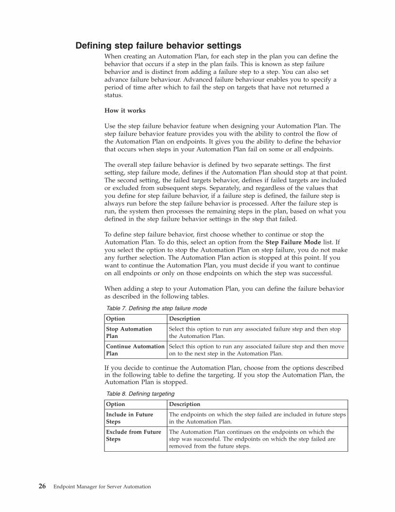
When adding a step to your Automation Plan, you can define the failure behavioras described in the following tables.
Table 7. Defining the step failure mode
Option Description
Stop AutomationPlan
Select this option to run any associated failure step and then stopthe Automation Plan.
Continue AutomationPlan
Select this option to run any associated failure step and then moveon to the next step in the Automation Plan.
If you decide to continue the Automation Plan, choose from the options describedin the following table to define the targeting. If you stop the Automation Plan, theAutomation Plan is stopped.
Table 8. Defining targeting
Option Description
Include in FutureSteps
The endpoints on which the step failed are included in future stepsin the Automation Plan.
Exclude from FutureSteps
The Automation Plan continues on the endpoints on which thestep was successful. The endpoints on which the step failed areremoved from the future steps.
26 Endpoint Manager for Server Automation
For Automation Plans created previously, default values are implemented. Thedefault values are Stop Automation Plan. When you open a legacy AutomationPlan and save it, the new attributes are added to the saved Automation Plan.
Step failure behavior and failure step targeting
Step failure behavior targeting is different from failure step targeting. When youadd a failure step to an Automation Plan, you can apply that failure step to allendpoints targeted in the step, or to only the endpoints on which the step failed. Ifyou add a failure step to a step and set the targeting for that failure step to applyto all endpoints, this targeting might be superseded if you have defined stepfailure behavior settings. If you have step failure mode defined as ContinueAutomation Plan and Exclude from Future Steps, any associated failure steptargeting is set automatically to Failed Only. The reason for this is that you do notwant to run the failure step against endpoints on which you want to run futuresteps, as this is defined in the step failure behavior settings. Instead, you want torun the failure step only on the endpoints that will be omitted from future steps.
Tracking Automation Plan actions and step failure behavior
You can view Automation Plan actions and step actions on the Automation PlanAction Status dashboard. If a step in your Automation Plan fails, the failure isindicated in the Status column. For steps that fail and do not have step failurebehavior behavior defined, a status of Failed is displayed in the Status column.For steps that fail and have step failure behavior defined, a status of Failed onsome targets is displayed, identifying that the step has step failure behaviordefined and has failed on some targets. Therefore, steps that have a status ofFailed are steps that have failed. In this case, the Automation Plan runs anyassociated failure step and then stops. Steps that have a status of Failed on sometargets are steps that have failed on some targets but the Automation Plancontinues to run, according to the settings defined by the step failure behavior. TheAutomation Plan continues to run on all endpoints or only on the endpoints onwhich the step was successful.
To view the endpoints on which the step failed, click the Detail icon for theparticular step.
Advanced failure behaviour
Advanced failure behaviour enables you to design your Automation Plan to runwithin scheduled maintenance windows by allowing you to specify a time limit forsteps to complete on target endpoints. This enables you to control how stepscomplete and to fail steps on endpoints on which the step has not completed aftera period of time that you specify. For example, if you have a maintenance windowof 60 minutes and need to include three steps in your plan, you can enableadvanced failure behaviour and enter a time period of say 20 minutes for eachstep. When a step runs and if 20 minutes elapse and the step has not completed onsome endpoints, the step is then failed on those endpoints. The advanced failurebehaviour settings are disabled by default.
To configure advanced failure behaviour:v If you are creating your plan, click the Default Settings icon for the step and go
to the Execution tab. Enable the check box for Fail incomplete targets and entera period of time, in minutes after which you want to fail the step on anyendpoints on which the step has not completed.
Chapter 3. Automation 27
v If you are running your plan, from the Take Automation Plan Action screen,click the Execution tab and enable the check box for Fail incomplete targets andenter a period of time, in minutes, after which you want to fail the step on anyendpoints on which the step has not completed.
Note: If you open a legacy Automation Plan that had timeout settings configured,the timeout targets are treated as failures. A message appears to indicate this.When you save the plan, the timeout behaviour
Setting step failure threshold
Setting a step failure threshold allows you to specify the percentage of failingtargets that defines the success or failure of the step. When you specify a stepfailure threshold, you are specifying the maximum percentage of failing targets forthe step to be considered successful. The step failure threshold manages thesuccess or failure of the step. For example, if you set the Step Failure Threshold at5%, and more than 5% of targeted endpoints, the step is treated as a failed stepand if you have set a failure step, the failure step will be executed. If you set theStep Failure Threshold at 5% and the step fails on 5% or fewer of targetedendpoints, the step will be treated as successful and a failure step, if set, will notbe run.
To set the step failure threshold:1. Open the Automation Plan that contains the step for which you want to
configure the step failure threshold and click Edit.2. Select the step for which you want to configure the step failure threshold.3. Click the Default Settings icon for the step and go to the Execution tab.4. In the Step Failure Threshold section, enter a percentage value for the
threshold at which to fail the step. For example, if you enter 5%, the step willbe failed if the step is unsuccessful on more than 5% of endpoints targeted. Thedefault value is any which means that if any endpoint fails the step, the step istreated as a failure and if you have defined a failure step for the step, thefailure step will be executed.
5. Click OK and then repeat this process for each step for which you want toconfigure a step failure threshold.
Targeting by computer groupFor each step in your Automation Plan, you can target computer groups as well asindividual computers. You can do this by saving computer groups as defaulttargets using the Default Settings feature when creating the Automation Plan, orwhen running or scheduling your Automation Plan from the Take AutomationPlan Action screen. When you target a computer group for a step, the list ofcomputers that belong to the computer group is determined at the time that thestep is executed. Therefore, if group membership changes between the time youdefine the step in the Automation Plan and when the Automation Plan is executed,the system determines which computers belong to the computer group that youhave targeted at the time that the step action is executed.
To specify a target computer group for a step, you must select an existingcomputer group and add it to the Selected Targets list. You cannot manually enterthe name of a computer group using The computers specified in the list of namesbelow. You can target by computer group either when creating your AutomationPlan using the Default Settings feature, or when running the Automation Planfrom the Take Automation Plan Action screen.
28 Endpoint Manager for Server Automation
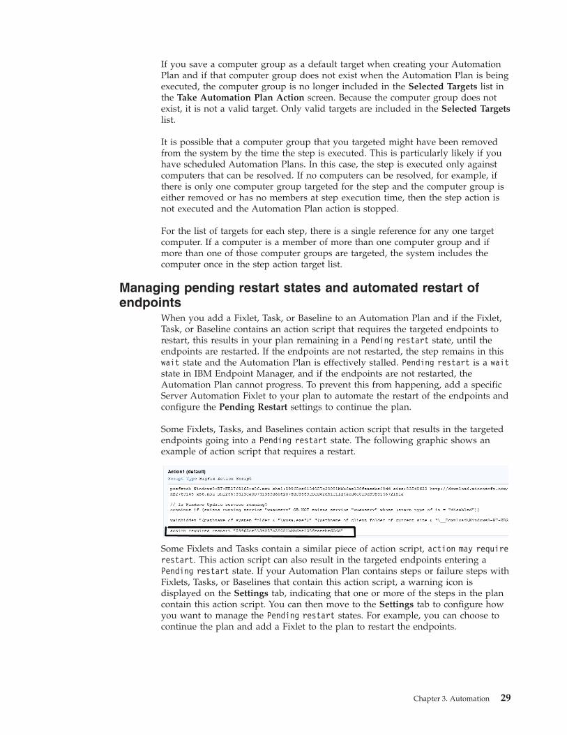
If you save a computer group as a default target when creating your AutomationPlan and if that computer group does not exist when the Automation Plan is beingexecuted, the computer group is no longer included in the Selected Targets list inthe Take Automation Plan Action screen. Because the computer group does notexist, it is not a valid target. Only valid targets are included in the Selected Targetslist.
It is possible that a computer group that you targeted might have been removedfrom the system by the time the step is executed. This is particularly likely if youhave scheduled Automation Plans. In this case, the step is executed only againstcomputers that can be resolved. If no computers can be resolved, for example, ifthere is only one computer group targeted for the step and the computer group iseither removed or has no members at step execution time, then the step action isnot executed and the Automation Plan action is stopped.
For the list of targets for each step, there is a single reference for any one targetcomputer. If a computer is a member of more than one computer group and ifmore than one of those computer groups are targeted, the system includes thecomputer once in the step action target list.
Managing pending restart states and automated restart ofendpoints
When you add a Fixlet, Task, or Baseline to an Automation Plan and if the Fixlet,Task, or Baseline contains an action script that requires the targeted endpoints torestart, this results in your plan remaining in a Pending restart state, until theendpoints are restarted. If the endpoints are not restarted, the step remains in thiswait state and the Automation Plan is effectively stalled. Pending restart is a waitstate in IBM Endpoint Manager, and if the endpoints are not restarted, theAutomation Plan cannot progress. To prevent this from happening, add a specificServer Automation Fixlet to your plan to automate the restart of the endpoints andconfigure the Pending Restart settings to continue the plan.
Some Fixlets, Tasks, and Baselines contain action script that results in the targetedendpoints going into a Pending restart state. The following graphic shows anexample of action script that requires a restart.
Some Fixlets and Tasks contain a similar piece of action script, action may requirerestart. This action script can also result in the targeted endpoints entering aPending restart state. If your Automation Plan contains steps or failure steps withFixlets, Tasks, or Baselines that contain this action script, a warning icon isdisplayed on the Settings tab, indicating that one or more of the steps in the plancontain this action script. You can then move to the Settings tab to configure howyou want to manage the Pending restart states. For example, you can choose tocontinue the plan and add a Fixlet to the plan to restart the endpoints.
Chapter 3. Automation 29
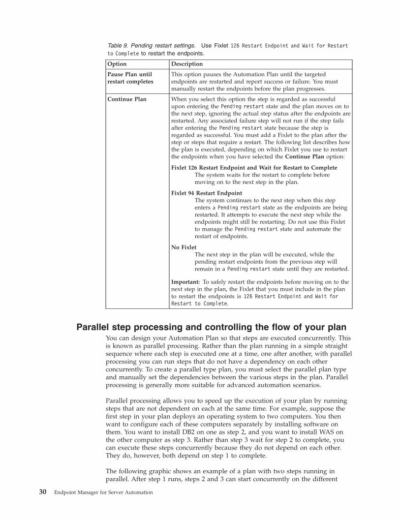
Table 9. Pending restart settings. Use Fixlet 126 Restart Endpoint and Wait for Restartto Complete to restart the endpoints.
Option Description
Pause Plan untilrestart completes
This option pauses the Automation Plan until the targetedendpoints are restarted and report success or failure. You mustmanually restart the endpoints before the plan progresses.
Continue Plan When you select this option the step is regarded as successfulupon entering the Pending restart state and the plan moves on tothe next step, ignoring the actual step status after the endpoints arerestarted. Any associated failure step will not run if the step failsafter entering the Pending restart state because the step isregarded as successful. You must add a Fixlet to the plan after thestep or steps that require a restart. The following list describes howthe plan is executed, depending on which Fixlet you use to restartthe endpoints when you have selected the Continue Plan option:
Fixlet 126 Restart Endpoint and Wait for Restart to CompleteThe system waits for the restart to complete beforemoving on to the next step in the plan.
Fixlet 94 Restart EndpointThe system continues to the next step when this stepenters a Pending restart state as the endpoints are beingrestarted. It attempts to execute the next step while theendpoints might still be restarting. Do not use this Fixletto manage the Pending restart state and automate therestart of endpoints.
No FixletThe next step in the plan will be executed, while thepending restart endpoints from the previous step willremain in a Pending restart state until they are restarted.
Important: To safely restart the endpoints before moving on to thenext step in the plan, the Fixlet that you must include in the planto restart the endpoints is 126 Restart Endpoint and Wait forRestart to Complete.
Parallel step processing and controlling the flow of your planYou can design your Automation Plan so that steps are executed concurrently. Thisis known as parallel processing. Rather than the plan running in a simple straightsequence where each step is executed one at a time, one after another, with parallelprocessing you can run steps that do not have a dependency on each otherconcurrently. To create a parallel type plan, you must select the parallel plan typeand manually set the dependencies between the various steps in the plan. Parallelprocessing is generally more suitable for advanced automation scenarios.
Parallel processing allows you to speed up the execution of your plan by runningsteps that are not dependent on each at the same time. For example, suppose thefirst step in your plan deploys an operating system to two computers. You thenwant to configure each of these computers separately by installing software onthem. You want to install DB2 on one as step 2, and you want to install WAS onthe other computer as step 3. Rather than step 3 wait for step 2 to complete, youcan execute these steps concurrently because they do not depend on each other.They do, however, both depend on step 1 to complete.
The following graphic shows an example of a plan with two steps running inparallel. After step 1 runs, steps 2 and 3 can start concurrently on the different
30 Endpoint Manager for Server Automation
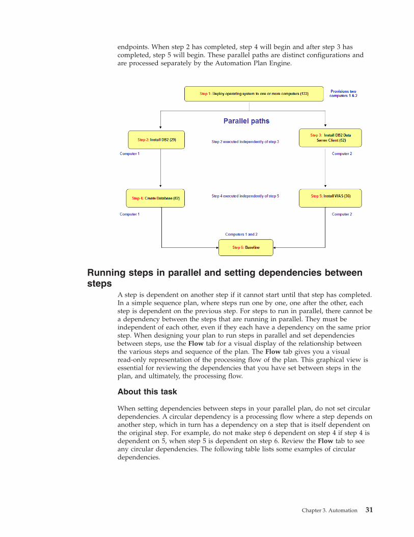
endpoints. When step 2 has completed, step 4 will begin and after step 3 hascompleted, step 5 will begin. These parallel paths are distinct configurations andare processed separately by the Automation Plan Engine.
Running steps in parallel and setting dependencies betweensteps
A step is dependent on another step if it cannot start until that step has completed.In a simple sequence plan, where steps run one by one, one after the other, eachstep is dependent on the previous step. For steps to run in parallel, there cannot bea dependency between the steps that are running in parallel. They must beindependent of each other, even if they each have a dependency on the same priorstep. When designing your plan to run steps in parallel and set dependenciesbetween steps, use the Flow tab for a visual display of the relationship betweenthe various steps and sequence of the plan. The Flow tab gives you a visualread-only representation of the processing flow of the plan. This graphical view isessential for reviewing the dependencies that you have set between steps in theplan, and ultimately, the processing flow.
About this task
When setting dependencies between steps in your parallel plan, do not set circulardependencies. A circular dependency is a processing flow where a step depends onanother step, which in turn has a dependency on a step that is itself dependent onthe original step. For example, do not make step 6 dependent on step 4 if step 4 isdependent on 5, when step 5 is dependent on step 6. Review the Flow tab to seeany circular dependencies. The following table lists some examples of circulardependencies.
Chapter 3. Automation 31
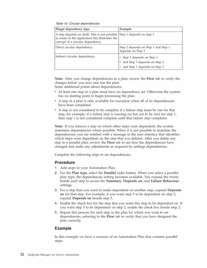
Table 10. Circular dependencies
Illegal dependency type Example
A step depends on itself. This is not possibleto create in the application but illustrates theconcept of a circular dependency.
Step 1 depends on step 1
Direct circular dependency. Step 2 depends on Step 1 and Step 1depends on Step 2
Indirect circular dependency. v Step 2 depends on Step 1
v and Step 3 depends on Step 2
v and Step 1 depends on Step 3
Note: After you change dependencies in a plan, review the Flow tab to verify thechanges before you save and run the plan.Some additional points about dependencies:v At least one step in a plan must have no dependency set. Otherwise the system
has no starting point to begin processing the plan.v A step in a plan is only available for execution when all of its dependencies
have been completed.v A step is not considered to be complete if a failure step must be run for that
step, for example, if a failure step is running (or has yet to be run) for step 1,then step 1 is not considered complete until that failure step completes.
Note: If you remove a step on which other steps were dependent, the systemmaintains dependencies where possible. When it is not possible to maintain thedependencies, you are notified with a message in the user interface that identifieswhich steps were dependent on the step that you deleted. After you delete anystep in a parallel plan, review the Flow tab to see how the dependencies havechanged and make any adjustments as required by settings dependencies.
Complete the following steps to set dependencies.
Procedure1. Add steps to your Automation Plan.2. For the Plan type, select the Parallel radio button. When you select a parallel
plan type, the dependencies setting becomes available. You expand the twistybeside each step to access the Summary, Depends on, and Failure Behavioursettings.
3. For a step that you want to make dependent on another step, expand Dependson for that step. For example, if you want step 5 to be dependent on step 2,expand Depends on beside step 5.
4. Enable the check box for the step that you want this step to be dependent on. Ifyou want step 5 to be dependent on step 2, enable the check box beside step 2.
5. Repeat this process for each step in the plan for which you want to setdependencies, referring to the Flow tab to verify that you have designed theplan correctly.
Example
In this example we have a scenario of an Automation Plan that contains parallelsteps.
32 Endpoint Manager for Server Automation
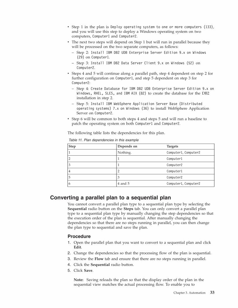
v Step 1 in the plan is Deploy operating system to one or more computers (133),and you will use this step to deploy a Windows operating system on twocomputers, Computer1 and Computer2.
v The next two steps will depend on Step 1 but will run in parallel because theywill be processed on the two separate computers, as follows:– Step 2: Install IBM DB2 UDB Enterprise Server Edition 9.x on Windows
(29) on Computer1.– Step 3: Install IBM DB2 Data Server Client 9.x on Windows (52) on
Computer2.v Steps 4 and 5 will continue along a parallel path, step 4 dependent on step 2 for
further configuration on Computer1, and step 5 dependent on step 3 forComputer2:– Step 4: Create Database for IBM DB2 UDB Enterprise Server Edition 9.x on
Windows, RHEL, SLES, and IBM AIX (82) to create the database for the DB2installation in step 2.
– Step 5: Install IBM WebSphere Application Server Base (Distributedoperating systems) 7.x on Windows (36) to install WebSphere ApplicationServer on Computer2.
v Step 6 will be common to both steps 4 and steps 5 and will run a baseline topatch the operating system on both Computer1 and Computer2.
The following table lists the dependencies for this plan.
Table 11. Plan dependencies in this example
Step Depends on Targets
1 Nothing. Computer1, Computer2
2 1 Computer1
3 1 Computer2
4 2 Computer1
5 3 Computer2
6 4 and 5 Computer1, Computer2
Converting a parallel plan to a sequential planYou cannot convert a parallel plan type to a sequential plan type by selecting theSequential radio button on the Steps tab. You can only convert a parallel plantype to a sequential plan type by manually changing the step dependencies so thatthe execution order of the plan is sequential. After manually changing thedependencies so that there are no steps running in parallel, you can then changethe plan type to sequential and save the plan.
Procedure1. Open the parallel plan that you want to convert to a sequential plan and click
Edit.2. Change the dependencies so that the processing flow of the plan is sequential.3. Review the Flow tab and ensure that there are no steps running in parallel.4. Click the Sequential radio button.5. Click Save.
Note: Saving reloads the plan so that the display order of the plan in thesequential view matches the actual processing flow. To enable you to
Chapter 3. Automation 33
successfully edit the plan and move steps in the sequential plan, the steps orderon the Steps tab must match the actual processing flow as displayed on theFlow tab.
6. Edit the sequential plan as required.
Automation Plan processingYour Automation Plan consists of a number of steps. When you run it in theAutomation Plans dashboard in the Server Automation domain, your AutomationPlan is processed by the Automation Plan Engine, one step at a time, in the orderthat is specified in the Automation Plan. If you run an Automation Plan from anyother dashboard or panel, the Automation Plan will fail.
When you run an Automation Plan from the Automation Plans dashboard in theServer Automation domain, the Automation Plan is processed in the followingstages:1. The Automation Plan Engine begins processing the Automation Plan action.2. The Automation Plan Engine opens a step action.3. The Automation Plan Engine processes the step action on the endpoints that
you specify.4. If the step action is successful, the Automation Plan Engine stops the step
action and proceeds to the next step action.5. If the status for a step action is Failure and the step has no failure step, the
Automation Plan action is stopped.6. If the Automation Plan contains a failure step for the failed step action, the
Automation Plan Engine runs the failure step before the Automation Planaction is stopped.
7. If the prior step action is successful, the Automation Plan Engine opens thenext step action and begins processing it.
To calculate the overall state of an Automation Plan step action, the AutomationPlan Engine gets the individual results that are retrieved from each of theendpoints. The Automation Plan Engine uses these results to calculate the overallstate of the step action. This state mapping information shows how that overallstate of the step action is used by the Automation Plan Engine to control therunning of the Automation Plan action. The Automation Plan Engine runs eachstep action in the Automation Plan based on a wait, success, or failure status. Forinformation about the states that map to the wait, success, or failure status, see“Running an Automation Plan” on page 41.
Important: Your Automation Plan actions are not visible to any other users, exceptusers with master operator privileges, even if the Show Other Operator's Actionsis set to Yes in the IBM Endpoint Manager console.
Stopping an Automation Plan action
When you stop an Automation Plan action, the step action that is in processcontinues to run and its status does not change to stopped. This step actionremains open.
You can stop the step action that is currently running by identifying it andstopping it. For information about how to stop Automation Plans and step actions,see “Stopping an Automation Plan” on page 47.
34 Endpoint Manager for Server Automation
Using failure steps in an Automation Plan
When you create an Automation Plan, you can optionally add a singlecorresponding failure step for each Automation Plan step. A failure step is a Fixletor a Task. A Baseline cannot be a failure step. If a step action fails and theAutomation Plan contains a failure step for the failed step, the Automation PlanEngine identifies and runs the failure step action. You can target a failure step torun on either all the endpoints for the corresponding step action or only on theendpoints that returned a failed status for the step action. When a failure stepaction processing is complete, the Automation Plan Engine stops the failure stepaction and then the Automation Plan action, regardless of the overall final status ofthe failure step action.
Automation Plan Engine shutdown and recoveryThe Automation Plan Engine detects particular conditions under which it can nolonger function correctly. For example, if credentials become invalid, theAutomation Plan Engine cannot function as normal. In these situations, theAutomation Plan Engine automatically shuts itself down. The IBM EndpointManager server plugin service is responsible for restarting the Automation PlanEngine after the period of time pre-configured in the PlanEngine.xml file in the\BigFix Enterprise\BES Server\Applications\Config directory for Windows or/var/opt/BESServer/Applications/Config/PlanEngine.xml for Linux. The defaultis 30 seconds, but you can change this by modifying the PlanEngine.xml file. Onrestart, the Automation Plan Engine resumes from the processing point at which itshut down. The Automation Plan Engine automatically recognizes any AutomationPlans that have already started, the stage of processing at which the shutdownoccurred, and then continues running these Automation Plans.
The Automation Plan Engine shutdown and recovery occurs in the followingsituations.
Table 12. Error conditions and recovery
Error condition Recovery
The Automation Plan Enginefails to communicate withWeb Reports.
Verify that the IBM Endpoint Manager Web Reports serviceis running. Verify also that the URL to the Web ReportsService is valid by opening a browser and pasting the URLand checking that you can log in using a valid user nameand password combination.
The Web Reports Servicemight be disabled.
An error is displayed if the Disable relevance evaluationoption has been set on the datasource in Web Reports. Tocorrect this, re-enable the Web Reports service bynavigating to Administration -> Datasources ->DataSource Options and clear the Disable relevanceevaluation check box.
Web Reports user credentialsfail or become invalid.
An attempt is made to contact the Web Reports serverusing the Reports Username and Password set at the timethe Automation Plan Engine was started. If thesecredentials have since changed, an error is displayed toindicate that the credentials for Web Reports are invalid. Tochange the credentials for the Web Reports Service, log onto Web Reports, go to Administration and select UserManagement. You can change the credentials from thispanel.
Chapter 3. Automation 35
Table 12. Error conditions and recovery (continued)
Error condition Recovery
IBM Endpoint Managerconsole user credentials failor become invalid.
The Automation Plan Engine attempts to run a simplefunction to contact the IBM Endpoint Manager API FixletMessage function using the Platform user name andpassword that were set at the time when the AutomationPlan Engine was started. An error is displayed if the wrongcredentials are used. To correct this, ensure that the username and password credentials are correct.
Editing an Automation PlanYou can change an Automation Plan by editing it in the Automation Plansdashboard. Typically, you might want to copy an existing plan or sample plan andthen customize or update it for a different automation scenario by changing stepsor by assigning different targets.
Before you begin
You must log on to the IBM Endpoint Manager console as a master operator or aconsole operator. You must have Custom Content permissions to create anAutomation Plan.
About this task
When you edit an Automation Plan, the list of available Automation Plans in theAutomation Plans dashboard is automatically refreshed. To manually refresh thelist of available Automation Plans, you must click the Refresh icon in theupper-right corner of the dashboard.
Each Automation Plan step is a Fixlet, Task, or Baseline. The steps are run in theorder that they are displayed in the Flow tab in the Automation Plans dashboard.You can view the IBM Endpoint Manager console Task, Fixlet or Baseline panelfor a step by clicking the Go to source icon for the step in the Steps tab. You canview the IBM Endpoint Manager console Task or Fixlet panel for a Component ina Baseline by clicking the Component name in the Steps tab. To return to the Stepstab, click Back in the menu bar.
Important: When you add a step to an Automation Plan, you are adding a copy ofa Fixlet, Task, or Baseline to the plan. If the Fixlet, Task, or Baseline changes after itis added to the Automation Plan, the changes are not reflected in the copy in theAutomation Plan. When the source content has changed, an icon is displayed toindicate that the source content has changed. You must then update yourAutomation Plan to include the latest changes. If you have access to the sourcecontent, you can update the Automation Plan by clicking the update content iconthat is displayed when source content has changed. You must be in edit mode toupdate the Automation Plan and you must click Save to save the updates.
Complete the following steps to edit an Automation Plan.
Procedure1. Open the Server Automation domain and from the navigation tree in the
Domain Panel, click Automation Plans. The Automation Plans dashboard is
36 Endpoint Manager for Server Automation
opened. A list of available Automation Plans is displayed in the dashboard. Tosort the list, click any column title. To filter all columns in the list, use thefilter field.
2. Select an Automation Plan from the list. The lower pane displays the selectedAutomation Plan data as read-only with the Steps tab selected by default.
3. Click Edit to edit the selected Automation Plan. The lower pane displays theselected Automation Plan data as editable fields.
4. To change the Automation Plan name and description, click the Details taband update the Name and Description fields. From the Details tab you canalso change the Domain, Category, Source, Source Release Date, andCategory Source Severity fields.
5. Click the Steps tab. If the plan type is a sequential plan, you can change theplan to a parallel plan by selecting the Parallel radio button beside Plan type.You then need to set the dependencies between the steps to control theprocessing flow of the plan. For information about how to set thedependencies, see “Parallel step processing and controlling the flow of yourplan” on page 30. If the plan type is a parallel plan, you cannot automaticallychange it to a sequential plan type by changing the Plan type radio button. Ifyou want to change a parallel plan type to a sequential plan, you mustmanually change the dependencies so that there are no parallel steps in theplan. Complete the following procedure to edit the steps in the AutomationPlan:a. If the plan is a parallel plan, to change the dependencies for a step,
expand Depends on for the step. Then check the box beside each step onwhich you want this step to depend. Review the Flow tab to verify thatthe plan processing flow.
b. To remove a step from an Automation Plan, click the Remove Step iconfor the step. If the plan is a parallel plan and if you remove a step onwhich other steps were dependent, you are notified with a message in theuser interface. Review the Flow tab and check if you need to makechanges to dependencies before running the plan.
c. To remove a failure step from a step, click the Remove Failure Step iconfor the step.
d. To change the action for a step that is a Fixlet or a Task, select one actionfrom the Action list. An action with a Script Type of URL is not displayedin the Action list.
6. Click Add Step to add steps to the Automation Plan. Complete the followingprocedure to add steps:a. In the Add Step panel, select Fixlets, Tasks, or Baselines from the Include
list to view Fixlets, Tasks or Baselines. The default value, All, displaysFixlets, Tasks and Baselines.
b. To filter the list of Fixlets, Tasks and Baselines, use the lists and the inputbox. To add or remove filters, use + - .
c. After you add the relevant search criteria, press Enter to search for Fixlets,Tasks and Baselines.
d. From the list of Fixlets, Tasks and Baselines, select one or more to add tothe Automation Plan.
e. When you finish selecting Fixlets, Tasks and Baselines, click Add. Thename and summary of each step in the Automation Plan is shown in theSteps tab. For sequential plans, the sequence is shown.
7. Optional: To save a set of default targets, default parameters, and filters forthe step:
Chapter 3. Automation 37
a. Click the Default Settings icon beside the Action dropdown menu for thestep.
b. From the Targets tab, search for and select the computers that you want tosave as default targets for the step and add them to the Selected Targetslist. You can also save default targets using the The same computerstargeted by step or The computers specified in the list of names options.If computers that you save as default targets do not exist when you arerunning the Automation Plan, the Selected Targets list in the TakeAutomation Plan Action dialog box is updated to reflect this. Dependingon security settings, users running the Automation Plan might not be ableto see all of the default targets that you set if they do not have sufficientpermissions.
c. If there are parameters that are associated with the action for the step, youcan set and save default parameters. However, you cannot save parametersfrom virtualization or middleware Fixlets. From the Parameters tab, enterthe parameters that you want to save as default parameters. You can entersome or all of the parameters associated with the action for the step. Notethe parameters that you set as defaults are not validated when you createthe Automation Plan, they are validated when you run the AutomationPlan. The Parameters tab is displayed only if there are parametersassociated with the action for the step. When you move your mouse overthe Default Settings icon after you have saved default parameters, atooltip is displayed providing information that default parameters havebeen set. This tooltip provides this information for any Fixlet that hasdefault parameters, not just for default parameters that you have saved. Ifa default parameter was set for the Fixlet when the Fixlet was created, thetooltip displays information that default parameters are set.
d. You can set and save filter criteria, including custom properties, for targetsfor the step. To save filters, select the filters that you want displayed in theTake Automation Plan Action dialog box when you are running theAutomation Plan.
Note: If you are saving custom properties as filters, these properties mustnot be reserved or default properties, and they cannot come from ananalysis. The custom properties must have been reported by at least onecomputer. If you export an Automation Plan containing custom propertiesand then import it on another server, and the custom properties are notspecified on the server to which you import the Automation Plan, thecustom properties are automatically deleted. If you delete the customproperties, they are also deleted from the Automation Plan.
e. Click OK and then Save to save the default targets, default parameters,and filters.
f. Repeat this process for each step in the Automation Plan for which youwant to save default targets or default parameters. If you delete theAutomation Plan, default targets, default parameters, and filters are alsodeleted.
8. To add a failure step to a step, click the Add Failure Step icon for the step. Afailure step is optional and can be a Fixlet or Task. A Baseline cannot be afailure step. A step can have only one failure step. Complete the following toadd a failure step to a step:a. In the Add Step panel, select Fixlets or Tasks from the Include list to view
Fixlets or Tasks. The default value, Fixlets and Tasks, displays both.b. To filter the list of Fixlets and Tasks, use the lists and the input box. To
add or remove filters, use + - .
38 Endpoint Manager for Server Automation
c. After you add the relevant search criteria, press Enter to search for Fixletsand Tasks.
d. From the list of Fixlets and Tasks, select one to add to the step.e. When you select a Fixlet or a Task, click Add. The failure step is shown in
the step in the Steps tab.f. To change the targeting for the failure step, expand Failure Step: for the
step. To target all endpoints that are targeted by the step action, select Allfrom the Targeting list. The default option is Failed Only. This optiontargets only the endpoints that return a failure status in the correspondingstep action.
g. To choose one action in the failure step, expand Failure Step: for the step.Select an action from the Action list. An action with a Script Type of URLis not displayed in the Action list.
9. If your plan is a sequential plan type, you can change the order and sequenceof steps by moving steps up or down in the Steps list. To move a step, selectthe step and click the Move Step icon. The Move Step After dialog box isdisplayed. Select the step after which you want the step that you are movingto be positioned. For parallel type Automation Plans, you use thedependencies to determine the processing flow of the plan. For completeinformation about setting dependencies, see “Parallel step processing andcontrolling the flow of your plan” on page 30.
10. Click Save to save all the changes to the Automation Plan.
Results
The changes that you made are added to the Automation Plan. The list of availableAutomation Plans in the Automation Plans dashboard is refreshed to display thechanges to the Automation Plan. You can run, edit, copy, or delete this AutomationPlan.
Copying an Automation PlanYou can create an Automation Plan by coping an existing Automation Plan. Youcan then edit the data in the Automation Plan that you copied.
Before you begin
You must log on to the IBM Endpoint Manager console as a master operator or aconsole operator. You must have Custom Content permissions to copy anAutomation Plan.
About this task
When you create an Automation Plan by copying an existing Automation Plan, allof the data in the original Automation Plan is copied into the new AutomationPlan. You can change the data in the new Automation Plan by using theAutomation Plan Editor in the Automation Plans dashboard. The new AutomationPlan can have the same name as the original Automation Plan. A unique ID isassigned to the new Automation Plan.
Important: You need Custom Content permissions to copy an Automation Plan. Ifyou do not have Custom Content permissions, Copy is disabled.
Chapter 3. Automation 39
Note: When you copy an Automation Plan, the list of available Automation Plansin the Automation Plans dashboard is automatically refreshed. To manually refreshthe list of available Automation Plans, you must click the Refresh icon in theupper-right corner of the dashboard.
Complete the following steps to copy an Automation Plan. For information aboutediting an Automation Plan, see Editing an Automation Plan.
Procedure1. Open the Server Automation domain.2. From the navigation tree in the Domain Panel, click Automation Plans. The
Automation Plans dashboard is opened. A list of available Automation Plans isdisplayed in the dashboard. To sort the list, click any column title. To filter allcolumns in the list, use the filter field.
3. Select an Automation Plan from the list. The lower pane displays the selectedAutomation Plan data as read-only.
4. Click Copy to copy the selected Automation Plan. A copy of the selectedAutomation Plan data is displayed in the lower pane as editable fields.
5. Click Save to save the changes to the new Automation Plan.
Results
You created an Automation Plan. The list of available Automation Plans in theAutomation Plans dashboard is refreshed to display the new Automation Plan.You can run, edit, copy, or delete this Automation Plan.
Deleting an Automation PlanYou can delete Automation Plans in the Automation Plans dashboard. If you wantto delete several Automation Plans, you must delete each Automation Planindividually. When an Automation Plan is deleted, the Automation Plan actionsand step actions are not deleted.
Before you begin
You must log on to the IBM Endpoint Manager console as a master operator or aconsole operator. You must have Custom Content permissions to delete anAutomation Plan.
About this task
When you delete an Automation Plan, the list of available Automation Plans in theAutomation Plans dashboard is automatically refreshed. To manually refresh thelist of available Automation Plans, click the Refresh icon in the upper-right cornerof the dashboard.
Important: Deleting an Automation Plan does not delete or stop any AutomationPlan actions or step actions for the deleted Automation Plan.
Procedure
To delete an Automation Plan, complete the following steps:1. Open the Server Automation domain.
40 Endpoint Manager for Server Automation
2. From the navigation tree in the Domain Panel, click Automation Plans. TheAutomation Plans dashboard is opened. A list of available Automation Plans isdisplayed in the dashboard. Click any column title to sort the list. Use the filterfield to filter all columns in the list.
3. Select an Automation Plan.4. To delete the selected Automation Plan, click Remove.
Results
You deleted an Automation Plan. The list of available Automation Plans in theAutomation Plans dashboard is refreshed to remove the deleted Automation Plan.
Running an Automation PlanYou run or schedule your Automation Plan from the Automation Plans dashboardin the Server Automation domain. If you run or schedule an Automation Plan fromany other dashboard or panel, it will fail. The Automation Plan Engine runs theAutomation Plan, one step at a time, by opening, processing, and then stoppingeach step in the order that you specify when you create the Automation Plan. TheAutomation Plan Engine calculates the state of each step and uses these states tocontrol the execution of the Automation Plan. In the Automation Plans dashboard,you must specify one or more endpoints for each step in an Automation Plan. Youmust specify the correct value for each parameter in a step or a failure step toensure that the step or failure step can run successfully. Only steps that are Fixletsor Tasks can have parameters.
Before you begin
You must log on to the IBM Endpoint Manager console as a master operator orconsole operator. If you log on as a console operator, you must have permission totarget each endpoint that you select. You must have Custom Content permissionsto run an Automation Plan. You must run the Automation Plan in the AutomationPlans dashboard in the Server Automation domain. If you run an Automation Planin any other dashboard or panel, it will fail.
To schedule an Automation Plan, ensure that the latest version of the AutomationPlan Engine is installed on your IBM Endpoint Manager console. If the latestversion is not installed, the Install Latest Automation Plan Engine Task isrelevant. To upgrade to the latest version of the Automation Plan Engine, see“Upgrading the Automation Plan Engine” on page 14.
About this task
The Automation Plan Engine opens a step as it begins to process it. When the stepprocessing is complete, the Automation Plan Engine stops the step. If the step issuccessful, the Automation Plan Engine then opens and processes the next step. Ifthe step fails, the Automation Plan Engine then opens the associated failure step, ifone exists, and processes it. To understand how the Automation Plan Enginecalculates if a step is complete or not, review the state mapping information that isdescribed here. To calculate the overall state of an Automation Plan step, theAutomation Plan Engine gets the individual results that are retrieved from each ofthe endpoints. The Automation Plan Engine uses these results to calculate theoverall state of the step. This state mapping information shows how that overallstate of the step is used by the Automation Plan Engine to control the running ofthe Automation Plan. The Automation Plan Engine runs each step in the
Chapter 3. Automation 41
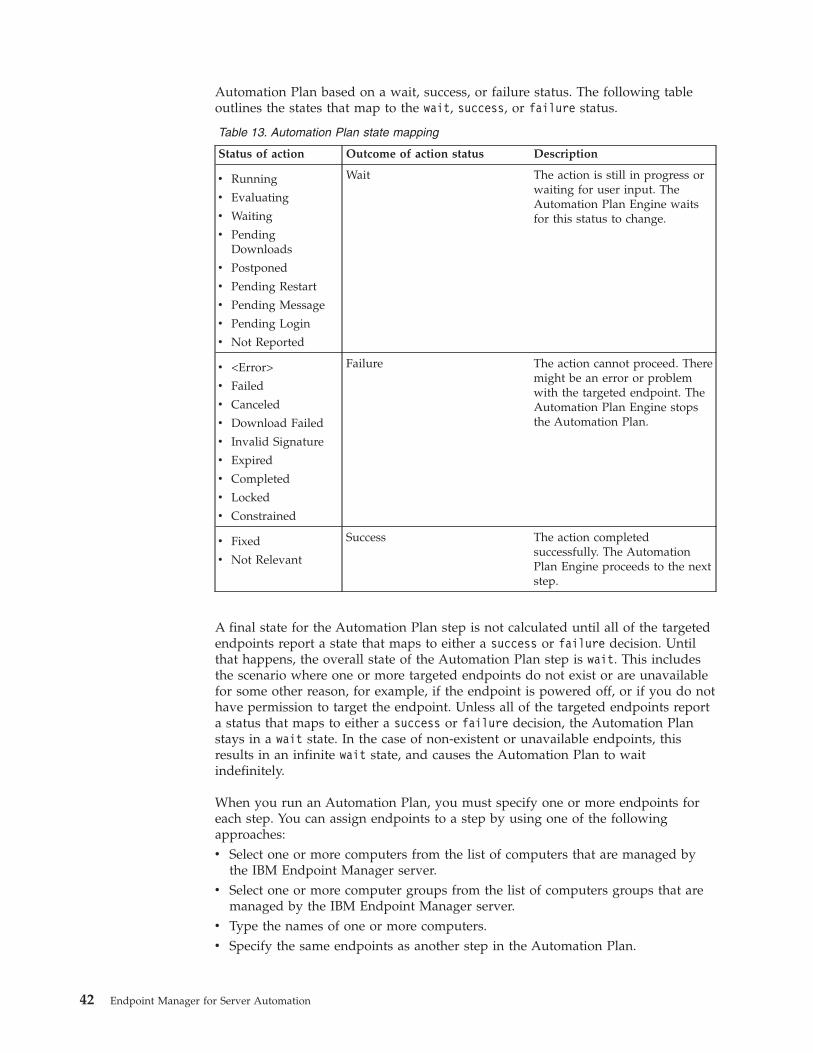
Automation Plan based on a wait, success, or failure status. The following tableoutlines the states that map to the wait, success, or failure status.
Table 13. Automation Plan state mapping
Status of action Outcome of action status Description
v Running
v Evaluating
v Waiting
v PendingDownloads
v Postponed
v Pending Restart
v Pending Message
v Pending Login
v Not Reported
Wait The action is still in progress orwaiting for user input. TheAutomation Plan Engine waitsfor this status to change.
v <Error>
v Failed
v Canceled
v Download Failed
v Invalid Signature
v Expired
v Completed
v Locked
v Constrained
Failure The action cannot proceed. Theremight be an error or problemwith the targeted endpoint. TheAutomation Plan Engine stopsthe Automation Plan.
v Fixed
v Not Relevant
Success The action completedsuccessfully. The AutomationPlan Engine proceeds to the nextstep.
A final state for the Automation Plan step is not calculated until all of the targetedendpoints report a state that maps to either a success or failure decision. Untilthat happens, the overall state of the Automation Plan step is wait. This includesthe scenario where one or more targeted endpoints do not exist or are unavailablefor some other reason, for example, if the endpoint is powered off, or if you do nothave permission to target the endpoint. Unless all of the targeted endpoints reporta status that maps to either a success or failure decision, the Automation Planstays in a wait state. In the case of non-existent or unavailable endpoints, thisresults in an infinite wait state, and causes the Automation Plan to waitindefinitely.
When you run an Automation Plan, you must specify one or more endpoints foreach step. You can assign endpoints to a step by using one of the followingapproaches:v Select one or more computers from the list of computers that are managed by
the IBM Endpoint Manager server.v Select one or more computer groups from the list of computers groups that are
managed by the IBM Endpoint Manager server.v Type the names of one or more computers.v Specify the same endpoints as another step in the Automation Plan.
42 Endpoint Manager for Server Automation
Important: You must not add a Baseline as a step if it contains any Componentthat prompts for parameter values when run. You cannot specify the values of theparameters in a step that is a Baseline. If you run an Automation Plan containing aBaseline that has a Component with an unspecified parameter, the AutomationPlan might fail or result in some other unexpected behavior. Only steps that areFixlets or Tasks can have parameters that prompt for values when run.
Scheduling an Automation Plan and Prefetch downloads
You can schedule an Automation Plan to run at a specified date and time. The dateand time that you specify in the Take Automation Plan Action panel is the IBMEndpoint Manager console local time. The IBM Endpoint Manager console convertsthe specified time to Coordinated Universal Time (UTC) and the Automation PlanEngine runs the Automation Plan at the specified UTC time. If the scheduled UTCtime and date are less than or equal to the current UTC time and date, theAutomation Plan Engine runs the Automation Plan immediately.
If you are scheduling your Automation Plan, you can choose to prefetch thecontent that needs to be downloaded. This option allows you to download thecontent required as part of the Automation Plan in advance of the execution of theAutomation Plan. This speeds up the execution of the Automation Plan so thatwhen the Automation Plan runs, the content has been downloaded in advance andruns much faster than if you do not choose this option. To use this option, youselect the Prefetch downloads check box when you are scheduling yourAutomation Plan. If you select this option, an open action is created for each stepin your Automation Plan that has a prefetch or download statement. You can viewthese actions from the Automation Plan Action Status dashboard.
Important: If prefetch download actions run in parallel with Automation Plansteps to the same endpoints, the step waits until all prefetch download steps arecompleted. Because the step action and the step download action share the samedownload, the IBM Endpoint Manager client detects this and waits for it tocomplete.
Important: There is a potential performance impact associated with using thePrefetch downloads option because an additional action is created for each stepthat requires software downloads. The recommended maximum number of openactions on the system is 2,500. For any given Automation Plan, an action is openfor the Automation Plan and also for each individual step in the Automation Plan.If you use the Prefetch downloads option, additional actions are created andopened for each step that requires software downloads. So instead of having twoopen actions per Automation Plan at any one point (one action for the AutomationPlan and one for the current step) there are additional actions opened for each stepthat requires software downloads.
Note: If an endpoint does not yet exist, the Automation Plan Engine waits untilthe endpoint is created before executing the step.
Complete the following steps to run or schedule an Automation Plan.
Procedure1. Open the Server Automation domain.2. From the navigation tree in the Domain Panel, click Automation Plans. The
Automation Plans dashboard is opened. A list of available Automation Plans
Chapter 3. Automation 43

is displayed in the dashboard. To sort the list, click any column title. To filterall columns in the list, use the filter field.
3. Select an Automation Plan from the list.4. Click Take Action. The Take Automation Plan Action panel is opened.5. To schedule the Automation Plan, specify the start time and date for the
Automation Plan by selecting a date from the Start Date list and a time fromthe Start Time list in the Plan Schedule pane. You can also type values for thedate and time in the Start Time field and the Start Date field. The time anddate that you specify is the IBM Endpoint Manager console local time. Thedefault values of the Start Date list and the Start Time list are the currentIBM Endpoint Manager console local time and date. You can select thePrefetch downloads option to download the content required for each step inthe Automation Plan in advance of the execution of the Automation Plan. Ifyou select this option, an open action is created for each step in yourAutomation Plan.
6. Select a step from the list. To view only the applicable endpoints for theselected step, select the Use applicability check box. To view all the endpointsthat are managed by the Tivoli® Endpoint Manager server, clear the Useapplicability check box. If there are no applicable endpoints for the selectedstep, the Use applicability check box is disabled.
7. To filter computers or computer groups that you want to target based on theirproperties, use the lists and the input box. To add or remove filters, click + or-. After you enter the relevant criteria to search, press Enter.
8. To assign one or more endpoints as targets for the step, use one of thefollowing methods:v Click Specific computers selected in the list below to select one or more
computer names as endpoints for the step:a. From the Include list, select Computers.b. To add all the computers in the Available Targets list to the Selected
Targets list, click Add All Displayed Targets.c. To add selected computers to the Selected Targets list, select one or
more computers in the Available Targets list and click Add HighlightedTargets.
v Click Specific computers selected in the list below to select one or morecomputer groups as endpoints for a step:a. From the Include list, select Computer Group.b. To add all the computer groups in the Available Targets list to the
Selected Targets list, click Add All Displayed Targets.c. To add selected computer groups to the Selected Targets list, select one
or more computer groups in the Available Targets list and click AddHighlighted Targets.
v Click The computers specified in the list below (one per line) to specifyone or more computers as endpoints for a step:a. Type or copy and paste the names of the computers that you want to
target.b. Enter one computer name per line.
v Select a step name from the Use same targets as list to specify the sameendpoints as another step in the Automation Plan.
Note: If the step has a set of default targets saved when the Automation Planis created, these targets are displayed in the Selected Targets list.
44 Endpoint Manager for Server Automation
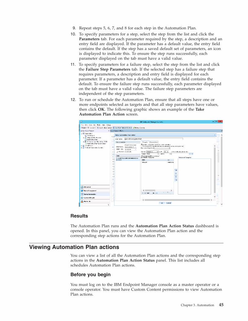
9. Repeat steps 5, 6, 7, and 8 for each step in the Automation Plan.10. To specify parameters for a step, select the step from the list and click the
Parameters tab. For each parameter required by the step, a description and anentry field are displayed. If the parameter has a default value, the entry fieldcontains the default. If the step has a saved default set of parameters, an iconis displayed to indicate this. To ensure the step runs successfully, eachparameter displayed on the tab must have a valid value.
11. To specify parameters for a failure step, select the step from the list and clickthe Failure Step Parameters tab. If the selected step has a failure step thatrequires parameters, a description and entry field is displayed for eachparameter. If a parameter has a default value, the entry field contains thedefault. To ensure the failure step runs successfully, each parameter displayedon the tab must have a valid value. The failure step parameters areindependent of the step parameters.
12. To run or schedule the Automation Plan, ensure that all steps have one ormore endpoints selected as targets and that all step parameters have values,then click OK. The following graphic shows an example of the TakeAutomation Plan Action screen.
Results
The Automation Plan runs and the Automation Plan Action Status dashboard isopened. In this panel, you can view the Automation Plan action and thecorresponding step actions for the Automation Plan.
Viewing Automation Plan actionsYou can view a list of all the Automation Plan actions and the corresponding stepactions in the Automation Plan Action Status panel. This list includes allschedules Automation Plan actions.
Before you begin
You must log on to the IBM Endpoint Manager console as a master operator or aconsole operator. You must have Custom Content permissions to view AutomationPlan actions.
Chapter 3. Automation 45
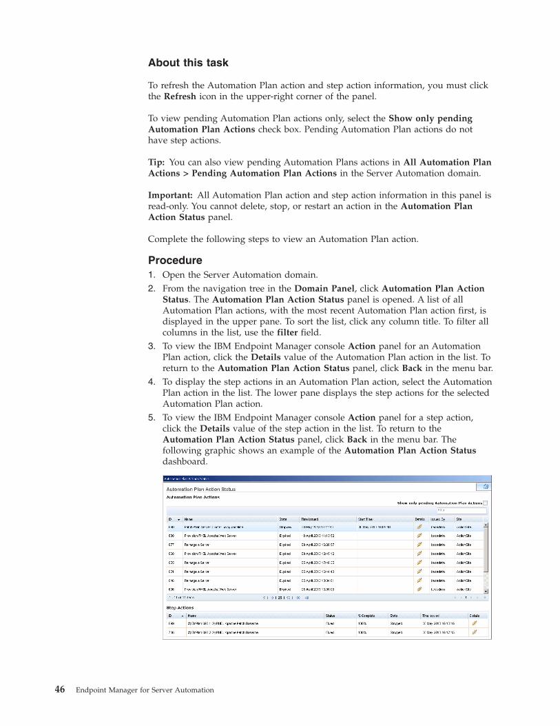
About this task
To refresh the Automation Plan action and step action information, you must clickthe Refresh icon in the upper-right corner of the panel.
To view pending Automation Plan actions only, select the Show only pendingAutomation Plan Actions check box. Pending Automation Plan actions do nothave step actions.
Tip: You can also view pending Automation Plans actions in All Automation PlanActions > Pending Automation Plan Actions in the Server Automation domain.
Important: All Automation Plan action and step action information in this panel isread-only. You cannot delete, stop, or restart an action in the Automation PlanAction Status panel.
Complete the following steps to view an Automation Plan action.
Procedure1. Open the Server Automation domain.2. From the navigation tree in the Domain Panel, click Automation Plan Action
Status. The Automation Plan Action Status panel is opened. A list of allAutomation Plan actions, with the most recent Automation Plan action first, isdisplayed in the upper pane. To sort the list, click any column title. To filter allcolumns in the list, use the filter field.
3. To view the IBM Endpoint Manager console Action panel for an AutomationPlan action, click the Details value of the Automation Plan action in the list. Toreturn to the Automation Plan Action Status panel, click Back in the menu bar.
4. To display the step actions in an Automation Plan action, select the AutomationPlan action in the list. The lower pane displays the step actions for the selectedAutomation Plan action.
5. To view the IBM Endpoint Manager console Action panel for a step action,click the Details value of the step action in the list. To return to theAutomation Plan Action Status panel, click Back in the menu bar. Thefollowing graphic shows an example of the Automation Plan Action Statusdashboard.
46 Endpoint Manager for Server Automation
Stopping an Automation PlanWhen you run an Automation Plan, an Automation Plan action is generated toprocess the Automation Plan. The Automation Plan action then generates stepactions, when required, when the preceding step is complete. If you want to stopan Automation Plan that is running, you must stop the Automation Plan actionbefore you stop the step action. To stop a pending Automation Plan action, youmust stop the Automation Plan action only.
About this task
To stop an Automation Plan that is running, you must first stop the AutomationPlan action, and then stop the open step action. Only one step action is open atany one time.
If you stop an Automation Plan step action without first stopping the AutomationPlan action, the Automation Plan Engine continues to process the Automation Planaction, generating new step actions as it does so.
The All Automation Plan Actions dashboard displays all Automation Plan actions,including all scheduled and pending Automation Plan actions, and all AutomationPlan step actions. The Automation Plan Actions dashboard displays allAutomation Plan actions including all scheduled and pending Automation Planactions. The Pending Automation Plan Actions dashboard displays pendingAutomation Plan actions only. The All Automation Plan Step Actions dashboarddisplays Automation Plan step actions only. From each dashboard, you can stopthe displayed actions.
If you stop a pending Automation Plan action, the state of the Automation Planaction is set to stopped and the Automation Plan action will not run at thescheduled time. The stopped Automation Plan action is not displayed on thePending Automation Plan Actions dashboard. A pending Automation Plan actionhas no step actions.
Complete the following steps to stop an Automation Plan.
Procedure1. To find the Automation Plan action, expand All Automation Plan Actions in
the Server Automation domain. Search for and select an Automation Planaction in the All Automation Plan Actions or the Automation Plan Actionsdashboards. If you want to stop a pending Automation Plan action, you cansearch for and select the Automation Plan action in the Pending AutomationPlan Actions dashboard.
2. Right-click the Automation Plan action and click stop. The step action that is inprocess continues to run and its status does not change to stop. This step actionremains open.
3. To identify an open Automation Plan step action in the stopped AutomationPlan:a. Open the Automation Plan Actions Status dashboard. Search for the
Automation Plan action that you stopped. Make a note of the AutomationPlan action ID value, in the first column.
b. From the Server Automation domain, expand the All Automation PlanActions node and click All Automation Plan Step Actions.
Chapter 3. Automation 47
c. In the search field on the All Automation Plan Step Actions dashboard,enter the ID value that you noted for the stopped Automation Plan action.The list of steps in the Automation Plan is displayed.
4. Identify the step action that is open, right-click the action, and click StopAction.
Results
The Automation Plan and all of the Automation Plan steps are stopped.
Exporting an Automation PlanYou can export an Automation Plan from the All Content domain in the IBMEndpoint Manager console. You can edit an exported Automation Plan in anexternal editor and then import the Automation Plan into a different console ordeployment. Other console operators can edit and import Automation Plans thatyou export.
Before you begin
You must log on to the IBM Endpoint Manager console.
About this task
When you export an Automation Plan, references or links to any custom Fixlets,Tasks, or Baselines in the Automation Plan are not exported. The Fixlets, Tasks, orBaselines in the exported Automation Plan execute correctly, but the link to theirsource from the exported Automation Plan does not display the action script.When you click the Task, Fixlet, or Baselines source, you are returned to theAutomation Plan action.
For information about how to import content such as Automation Plans, seeImporting content.
Complete the following steps to export an Automation Plan.
Procedure1. Open the All Content domain.2. From the navigation tree in the Domain Panel, click Fixlets and Tasks. A list of
Fixlets, Tasks, and Automation Plans is displayed in the upper pane.3. To display all the Fixlets, Tasks, and Automation Plans, click Show
Non-Relevant Content in the menu bar. To sort the list, click any column title.To filter all columns in the list, use the Search Fixlets and Tasks field.
4. Select an Automation Plan from the list. The lower pane displays the selectedAutomation Plan data.
5. Click Export to export the selected Automation Plan.6. In the Save As window, specify File name and click Save.
Results
The Automation Plan is exported to a .BES file. You can edit the Automation Planin an external editor or copy it to another console or deployment.
48 Endpoint Manager for Server Automation
Setting or changing the default values of parametersYou can set or change default values of parameters that are not displayed whenyou are editing an Automation Plan from the Automation Plans dashboard. Whenyou are editing an Automation Plan, you might not be able to change parametervalues using the user interface. However, you can change the default values ofparameters by changing the action script for the Automation Plan in the AllContent domain.
About this task
Complete the following steps to change the default values of parameters.
Procedure1. Open the All Content domain.2. In the Fixlets and Tasks tree, search for and select the Automation Plan for
which you want to change the default parameters.3. Click the Edit button.4. Click the Actions tab to view the action script.5. In the action script section, search for the action parameter query string and
locate the parameter for which you want to change the default value.6. To set the default value, change the With default value for the parameter to
the value that you want to specify as the default.7. Save the action script.
Chapter 3. Automation 49

50 Endpoint Manager for Server Automation
Chapter 4. Virtualization
Virtualization is a software technology that allows multiple operating systems torun on the same host computer at the same time. Additional uses of virtualizationinclude the quick creation of new systems for testing, training, and demonstration.Using virtualized computers saves the cost of hardware, management, andadministration of the server infrastructure.
A virtual server is composed of software and acts like a complete hardware systemfrom processor to network card in a self-contained, isolated software environment,enabling the simultaneous operation of otherwise incompatible systems. A virtualserver has no hardware components. Virtual servers are based on host platforms. Ahost platform is a physical computer that has hosting capabilities and can hostmany virtual servers.
In Server Automation, you manage your virtualization infrastructure using Tasks.
VMwareYou can deploy and configure a management extender plug-in for VMware. Youcan then manage VMware virtual machines from within the IBM EndpointManagement console.
Setup and maintenanceThis section provides documentation about setup and maintenance tasks that youcan complete for VMware virtualization.
Use the information in this section for instructions and important informationabout how to set up the virtualization environment for VMware.
Installing the management extender for VMwareBefore you work with IBM Endpoint Manager for Server Automation virtualizationfeatures, you must install a management extender to communicate with theVMware vCenter or ESX host. Before you install the management extender, youmust enable the license for Virtual Endpoint Manager.
Before you begin
You must have a relay server or a root server Version 9.0 or later. A VMwaremanagement extender must not be already installed on the server. Because of theworkload that is imposed on the system by the management extender, it isrecommended that you install the management extender on a relay server and nota root server.
Important: You must ensure that the license for Virtual Endpoint Manager isenabled. To enable the Virtual Endpoint Manager license, go to the BigfixManagement domain, navigate to License Overview > Lifecycle Management.From the list of Available Sites, enable Virtual Endpoint Manager. When VirtualEndpoint Manager is enabled, it disappears from the Available Sites list and isdisplayed in the Enabled Sites list.
51
Procedure1. Open the Server Automation domain.2. From the navigation tree in the Server Automation domain, click Virtualization
> Setup and Maintainance > Deploy VMware Components.3. In the Deploy VMware Components window, select the Deploy Management
Extender for VMware vCenter Task.4. In the Task: Deploy Management Extender for VMware vCenter window,
click Take Action.5. In the Take Action dialog box, ensure Specific computers selected in the list
below is selected.6. In the Computer Name list, select a relay server or a root server and click OK.
Results
In the Action: Deploy Management Extender for VMware vCenter window, youcan check the status of the installation. When the status changes to Completed, themanagement extender for VMware is installed.
What to do next
After you install the management extender for VMware, you must configure themanagement extender with your VMware system details. For more informationabout configuring the management extender, see “Configuring managementextenders.”
Configuring management extendersBefore you can begin working with the different Virtualization features, you mustconfigure a relay server or a root server to communicate with a specific VMwarevCenter or ESX host. You can use ESX version 5.1 or lower.
Before you begin
Before you can configure the management extender, you must install themanagement extender for VMware. The VMware credentials that are used to log inmust be part of the Administrator group in VMware. If you have Read Onlypermissions, you cannot correctly configure the management extender and cannotuse any of the Virtualization capabilities.
Procedure1. Open the Server Automation domain.2. From the navigation tree in the Server Automation domain, click Virtualization
> Setup and Configuration Wizard to open the Configure ManagementExtenders list.
3. In the Configure Management Extenders pane, select a relay server or a rootserver from the Deployed Extenders list and click Configure.
4. In the Configure Extender area, enter the Server name. You can enter either acomplete URL or the server address. If you enter the server name, a URLhttps://<servername>:<port>/sdk/webservice/ is generated. This URL cancause problems if you want to manage a single ESX host virtual environmentbecause a single ESX host requires a URL with an ending: https://<servername>:<port>/sdk/vimService. If you want to manage a single ESX hostvirtual environment, ensure that you tick the Enter vCenter's web service URLbox in the Configure Extender window and enter the correct version of theURL.
52 Endpoint Manager for Server Automation
5. In the Configure Extender area, enter the Admin user and Password of thespecific VMware system that you want to configure with a relay server or aroot server and click Configure VMware vCenter Management Extender...
6. In the Take Action dialog box, select a relay server or a root server that youwant to target from the Computer Name list and click OK.
Results
When the management extender is completed, the Status changes to Completed inthe Action: Configure VMware vCenter Management Extender window.
Upgrading the management extender plug-inUsing the VMware Upgrade vCenter Plugin Task, you can upgrade the VMwarevCenter plug-in component of the management extender for VMware vCenter.
Before you begin
The VMware Upgrade vCenter Plugin Task checks if the process vCenterplugin.exe is running and waits for this process to finish before it takes action.
Procedure1. Open the Server Automation domain.2. From the navigation tree in the Server Automation domain, click Virtualization
> Setup and Maintenance > Upgrade VMware Components.3. From the Upgrade VMware Components list, select VMware Upgrade vCenter
Plugin.4. In the VMware Upgrade vCenter Plugin window, click Take Action.5. In the Take Action dialog box, ensure Specific computers selected in the list
below is selected and from the list of Computer Names, select the computername which is configured with the management extender and click OK.
Results
When the management extender plug-in is upgraded, the Status changes toCompleted in the Action: VMware Upgrade vCenter Plugin window.
Configuring your Windows administrator passwordTo create Windows virtual machines from a template, you must set your Windowsadministrator password in VMware. The Configuring VMware ManagementExtender for Windows Templates Task configures the Windows administratorpassword as the initial password. Using this wizard, you can set your Windowsadministrator password on a VMware management extender. First, the wizardencrypts the password, then sends the encrypted password to the managementextender. You can then proceed to create a Windows virtual machine from atemplate.
Before you begin
You must ensure that the SSL Encryption Analysis for Management Extenderanalysis is active. If this analysis is not activated, a warning message is displayedin the Configuring VMware Management Extender for Windows Templates Task.You cannot proceed to configure your Windows administrator password withoutactivating the analysis. After you activate the analysis, it can take a few minutes togather. To check the status of the analysis, from the navigation tree in the ServerAutomation domain click Virtualization > Setup and Maintenance > Activate
Chapter 4. Virtualization 53
Analyses. In the Activate Analysis list, select SSL Encryption Analysis forManagement Extender. In the Analysis: SSL Encryption Analysis forManagement Extender window, click the Results tab. When the Results windowis populated with one or more computer names, the analysis is activated. If any ofthe computer names displays the message "not reported", the analysis is notgathered.
Procedure1. Open the Server Automation domain.2. From the navigation tree in the Server Automation domain, click Virtualization
> Setup and Maintenence > Configuring VMware Management Extender forWindows Templates.
3. To filter the list of management extenders that are not configured with aWindows administrator password, enable the Show Extenders with passwordsnot set check box.
4. From the VMware Management Extender list, select the management extenderthat you want to use to configure your Windows administrator password.
5. In the Administrator Password field, enter your Windows administratorpassword. The password must contain only alphanumeric characters.
6. In the Confirm Administrator Password field, enter your Windowsadministrator password details again to confirm that the details are correct andclick Take Action.
7. In the Take Action dialog box, select the computer that you want to use toconfigure your Windows administrator password.
Results
When the Windows administrator password is set in VMware, the Status changesto Completed in the Action: VMware Management Extender for VMwareWindows Templates window.
Removing the management extender for VMwareUsing the Remove Management Extender for VMware vCenter Task, you canremove the management extender for VMware.
About this task
The Remove Management Extender for VMware vCenter Task removes themanagement extender but does not remove the list of computers that areassociated with a relay server or a root server. If you reconfigure the managementextender at a later stage, the reconfiguration might cause computers with duplicatenames to be displayed within the IBM Endpoint Manager console. To removeunwanted computers from the database of the IBM Endpoint Manager console,navigate to the All Content domain, select Computers and from the Computerslist, select the computers that you want to remove, right-click, and select Removefrom Database.
Procedure1. Open the Server Automation domain.2. From the navigation tree in the Server Automation domain, click Virtualization
> Setup and Maintainance > Remove VMware Components.3. In the Remove VMware Components window, select the Remove
Management Extender for VMware vCenter Task.
54 Endpoint Manager for Server Automation
4. In the Task: Remove Management Extender for VMware vCenter window,click Take Action.
5. In the Take Action dialog box, ensure Specific computers selected in the listbelow is selected.
6. In the Computer Name list, select the computer from which you want toremove the management extender and click OK.
Results
In the Action: Remove Management Extender for VMware vCenter window, youcan check the status of the uninstall. When the status changes to Completed, themanagement extender for VMware is uninstalled from the root server or the relayserver.
Virtual server overviewThe Virtual Server Overview dashboard lists the hosts and virtual machinesreported by the management extender through the VMware API. You can use theVirtual Server Overview to view the attributes of each host and virtual machine.You can also filter the lists of hosts and virtual machines by their attributes. Toview the Virtual Server Overview, in the Server Automation domain, selectVirtualization > Virtual Server Overview.
To view the Virtual Server Overview, you must ensure that the analyses VMwareHost Overview and VMware VM Overview are active. If these analyses are notactivated, a warning message is displayed in the Virtual Server Overview list. Youcannot proceed to view the overview without activating the analyses. After youactivate the analyses, it can take a few minutes to gather. To check the status of theanalyses, from the navigation tree in the Server Automation domain, clickVirtualization > Setup and Maintenance > Activate Analyses. In the ActivateAnalysis list, ensure that the Status changes from Not Activated to ActivatedGlobally. In the Activate Analyses list, click both VMware Host Overview andVMware VM Overview individually. In the Analysis: VMware Host Overviewand the VMware VM Overview window, click the Results tab. When the Resultswindow is populated with one or more computer names, the analysis is activated.If any of the computer names displays the message "not reported", the analysis isnot gathered.
To view hosts, click the Hosts tab in the Virtual Server Overview. In the Hoststab, you can view the following host attributes.
Table 14. Virtual Server Overview - Hosts
Requirement Description
Link to Host Contains a link to a page with full specifications of the host.
Name Displays the host name.
Operating System Displays the operating system of the host.
CPU count Displays the logical processor count of the host.
Datacenter Displays the datacenter that contains the host.
Status Displays the status of the host.
Memory size Displays the memory size of the host.
NIC Count Displays the number of network interface cards.
VM and Template Count Displays the number of virtual machines and templates thatare on the host.
Chapter 4. Virtualization 55
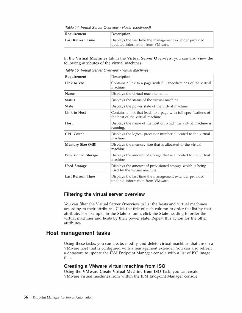
Table 14. Virtual Server Overview - Hosts (continued)
Requirement Description
Last Refresh Time Displays the last time the management extender providedupdated information from VMware.
In the Virtual Machines tab in the Virtual Server Overview, you can also view thefollowing attributes of the virtual machines.
Table 15. Virtual Server Overview - Virtual Machines
Requirement Description
Link to VM Contains a link to a page with full specifications of the virtualmachine.
Name Displays the virtual machine name.
Status Displays the status of the virtual machine.
State Displays the power state of the virtual machine.
Link to Host Contains a link that leads to a page with full specifications ofthe host of the virtual machine.
Host Displays the name of the host on which the virtual machine isrunning.
CPU Count Displays the logical processor number allocated to the virtualmachine.
Memory Size (MB) Displays the memory size that is allocated to the virtualmachine.
Provisioned Storage Displays the amount of storage that is allocated to the virtualmachine.
Used Storage Displays the amount of provisioned storage which is beingused by the virtual machine.
Last Refresh Time Displays the last time the management extender providedupdated information from VMware.
Filtering the virtual server overview
You can filter the Virtual Server Overview to list the hosts and virtual machinesaccording to their attributes. Click the title of each column to order the list by thatattribute. For example, in the State column, click the State heading to order thevirtual machines and hosts by their power state. Repeat this action for the otherattributes.
Host management tasks
Using these tasks, you can create, modify, and delete virtual machines that are on aVMware host that is configured with a management extender. You can also refresha datastore to update the IBM Endpoint Manager console with a list of ISO imagefiles.
Creating a VMware virtual machine from ISOUsing the VMware Create Virtual Machine from ISO Task, you can createVMware virtual machines from within the IBM Endpoint Manager console.
56 Endpoint Manager for Server Automation
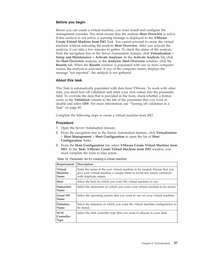
Before you begin
Before you can create a virtual machine, you must install and configure themanagement extender. You must ensure that the analysis Host Overview is active.If this analysis is not active, a warning message is displayed in the VMwareCreate Virtual Machine from ISO Task. You cannot proceed to create the virtualmachine without activating the analysis Host Overview. After you activate theanalysis, it can take a few minutes to gather. To check the status of the analysis,from the navigation tree in the Server Automation domain, click Virtualization >Setup and Maintenance > Activate Analyses. In the Activate Analysis list, clickthe Host Overview analysis, in the Analysis: Host Overview window, click theResults tab. When the Results window is populated with one or more computernames, the analysis is activated. If any of the computer names displays themessage "not reported", the analysis is not gathered
About this task
This Task is automatically populated with data from VMware. To work with otherdata, you must turn off validation and enter your own values into the parameterfield. To override the data that is provided in the form, check whether a buttonexists in the Validation column to the left of the parameter that you want todisable and select OFF. For more information, see “Turning off validation in aTask” on page 69.
Complete the following steps to create a virtual machine from ISO.
Procedure1. Open the Server Automation domain.2. From the navigation tree in the Server Automation domain, click Virtualization
> Host Management > Host Configuration to open the list of HostConfiguration Tasks.
3. From the Host Configuration list, select VMware Create Virtual Machine fromISO. In the Task: VMware Create Virtual Machine from ISO window, youmust complete the form to take action.
Table 16. Parameter list for creating a virtual machine
Requirement Description
VirtualMachineName
Enter the name of the new virtual machine to be created. Ensure that yougive your virtual machine a unique name to avoid any future confusionwith duplicate names.
Host Select the host on which you want the virtual machine to run.
DatacenterName
Select the datacenter on which you want your virtual machine to be stored.
Guest OSName
Select the operating system that you want to run on your virtual machine.
DatastoreName
Select the datastore in which you want the virtual machine configuration tobe stored.
SCSIControllerType
Select the disk controller type that you want to allocate to your disk.
Chapter 4. Virtualization 57
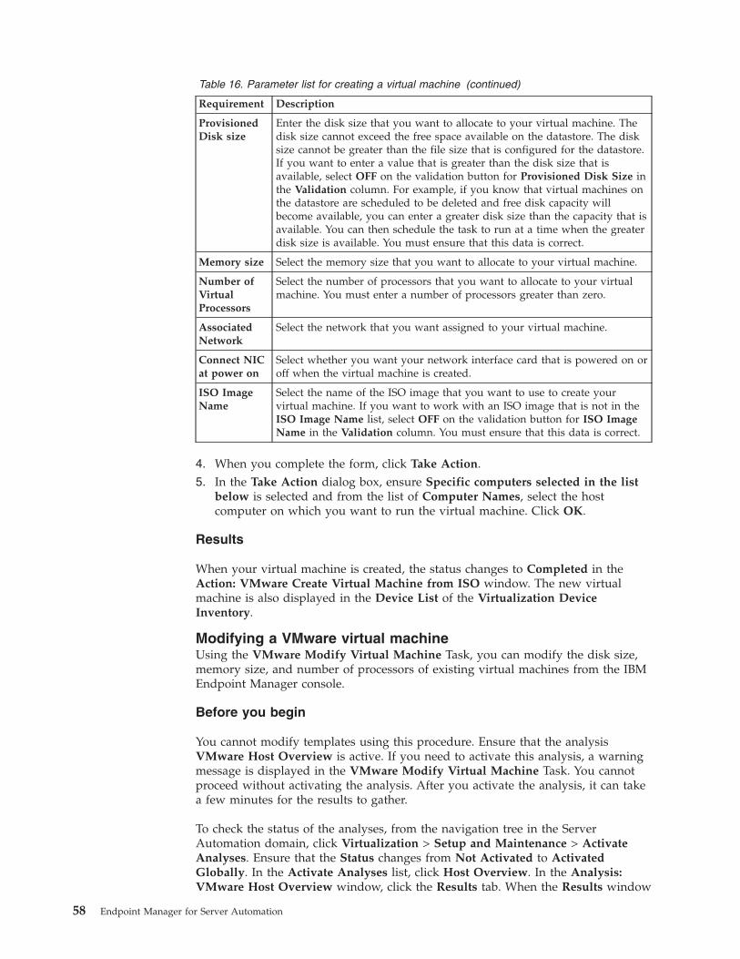
Table 16. Parameter list for creating a virtual machine (continued)
Requirement Description
ProvisionedDisk size
Enter the disk size that you want to allocate to your virtual machine. Thedisk size cannot exceed the free space available on the datastore. The disksize cannot be greater than the file size that is configured for the datastore.If you want to enter a value that is greater than the disk size that isavailable, select OFF on the validation button for Provisioned Disk Size inthe Validation column. For example, if you know that virtual machines onthe datastore are scheduled to be deleted and free disk capacity willbecome available, you can enter a greater disk size than the capacity that isavailable. You can then schedule the task to run at a time when the greaterdisk size is available. You must ensure that this data is correct.
Memory size Select the memory size that you want to allocate to your virtual machine.
Number ofVirtualProcessors
Select the number of processors that you want to allocate to your virtualmachine. You must enter a number of processors greater than zero.
AssociatedNetwork
Select the network that you want assigned to your virtual machine.
Connect NICat power on
Select whether you want your network interface card that is powered on oroff when the virtual machine is created.
ISO ImageName
Select the name of the ISO image that you want to use to create yourvirtual machine. If you want to work with an ISO image that is not in theISO Image Name list, select OFF on the validation button for ISO ImageName in the Validation column. You must ensure that this data is correct.
4. When you complete the form, click Take Action.5. In the Take Action dialog box, ensure Specific computers selected in the list
below is selected and from the list of Computer Names, select the hostcomputer on which you want to run the virtual machine. Click OK.
Results
When your virtual machine is created, the status changes to Completed in theAction: VMware Create Virtual Machine from ISO window. The new virtualmachine is also displayed in the Device List of the Virtualization DeviceInventory.
Modifying a VMware virtual machineUsing the VMware Modify Virtual Machine Task, you can modify the disk size,memory size, and number of processors of existing virtual machines from the IBMEndpoint Manager console.
Before you begin
You cannot modify templates using this procedure. Ensure that the analysisVMware Host Overview is active. If you need to activate this analysis, a warningmessage is displayed in the VMware Modify Virtual Machine Task. You cannotproceed without activating the analysis. After you activate the analysis, it can takea few minutes for the results to gather.
To check the status of the analyses, from the navigation tree in the ServerAutomation domain, click Virtualization > Setup and Maintenance > ActivateAnalyses. Ensure that the Status changes from Not Activated to ActivatedGlobally. In the Activate Analyses list, click Host Overview. In the Analysis:VMware Host Overview window, click the Results tab. When the Results window
58 Endpoint Manager for Server Automation
is populated with one or more computer names, the analysis is activated. If any ofthe computer names displays the message "not reported", the analysis is notgathered.
For non-English users: VMware vCenter supports only Simplified Chinese,Japanese, German and French. You can use this Task only if the console languagethat you selected in IBM Endpoint Manager console is identical to the consolelanguage selected in VMware.
About this task
This Task is automatically populated with data from VMware. To work with otherdata, you need to turn off validation and enter your own values into the parameterfield. To override the data that is provided in the form, check whether a buttonexists in the Validation column to the left of the parameter that you want todisable and select OFF. For more information, see “Turning off validation in aTask” on page 69.
Complete the following steps to modify a virtual machine.
Procedure1. Open the Server Automation domain2. From the navigation tree in the Server Automation domain, click
Virtualization > Host Management > Host Configuration. This opens the listof Host Configuration Tasks.
3. From the Host Configuration list, select VMware Modify Virtual Machine.4. In the Task: VMware Modify Virtual Machine window, from the Host list,
select the host on which the virtual machine that you want to modify isrunning.
5. From the Virtual Machine Name list, select the name of the virtual machinethat you want to modify. If the virtual machine name that you want to modifyis displayed more than once in the Virtual Machine Name list, you can verifythat the virtual machine that you select is correct by viewing the VirtualMachine UUID and the IP Address field. If you want to modify a virtualmachine that does not display in the Virtual Machine Name list, select OFFon the validation button for Virtual Machine Name in the Validation column.For example, if you want to modify a virtual machine that does not exist, butis scheduled to be created, you can turn off validation and enter the name ofthe virtual machine to be modified. You can then schedule the Task to takeaction when the virtual machine exists. If you disable validation for VirtualMachine Name, the validation for the Power State and Disk Size is alsodisabled. The validation for Power State and Disk Size is disabled becausethe IBM Endpoint Manager console cannot validate that the power state ordisk size of a virtual machine name that has been entered while validation isdisabled. You must ensure that the virtual machine name that you enter iscorrect or the Task fails in VMware.
6. You can use the Power State field to view whether the virtual machine thatyou want to work with is powered on or off. VMware only allows you tomodify virtual machines that are powered off. However, if you want tomodify a virtual machine that is currently powered on, but is scheduled to bepowered off at a later stage, select OFF on the validation button for PowerState in the Validation column. You can then schedule the Task to take actionwhen the virtual machine is powered off.
Chapter 4. Virtualization 59
7. From the Disk Name list, select the disk that you want to modify. You can usethe Maximum Size field to view the maximum size that you can configure avirtual machine.
8. In the Maximum file Size field, you can view the maximum file size that canbe allocated to a virtual machine that is created on the datastore. You cannotmodify the disk size of the virtual machine to be greater than the maximumfile size allowed for the datastore.
9. In the Datastore free space field, you can view the free space available on thedatastore. You can add the value that is displayed in the Datastore free spacefield to the value that is displayed in the Disk Size field.
10. In the Disk Size field, enter the disk size that you want to allocate to yourvirtual machine. In VMware, you can only increase the disk size, you cannotdecrease it. You cannot exceed the maximum file size configured for thedatastore. You cannot exceed the free space available on the datastore. If youwant to enter a value for the disk size that is greater than the size that iscurrently available on the datastore, select OFF on the validation button forthe Disk Size in the Validation list. For example, if you know that virtualmachines on the datastore are scheduled to be deleted and free disk capacitywill become available, you can enter a greater disk size than that which iscurrently available. You can schedule the Task to take action when more diskspace becomes available. You must ensure that this information is correct. Youcannot modify a virtual machine with a provisioned disk size greater than theMaximum file size for the datastore even if you disable validation.
11. From the Memory Size list, select the memory size that you want to allocateto your virtual machine.
12. In the Number of Virtual Processors list, select the number of processors thatyou want to allocate to your virtual machine. You must enter a numbergreater than zero.
13. In the Take Action dialog box, ensure that Specific computers selected in thelist below is selected and from the list of Computer Names, select the host ofthe virtual machine that you want to modify and click OK.
Results
When your virtual machine is modified, the Status changes to Completed in theAction: VMware Modify Virtual Machine window.
Deleting a virtual machineUsing the VMware Delete Virtual Machine Task, you can delete VMware virtualmachines from within the IBM Endpoint Manager console.
Before you begin
Ensure that the analysis VMware Host Overview is active. If this analysis must beactivated, a warning message is displayed in the VMware Delete Virtual MachineTask. You cannot proceed without activating the analysis. Activating the analysiscan take a few minutes.
To check the status of the analysis, from the navigation tree in the ServerAutomation domain, click Virtualization > Setup and Maintenance > ActivateAnalyses. In the Activate Analyses list, ensure that the VMware Host Overviewanalysis changes from Not Activated to Activated Globally and click the VMwareHost Overview analysis. In the Analysis: VMware Host Overview window, clickthe Results tab. When the Results window is populated with one or more
60 Endpoint Manager for Server Automation
computer names, the analysis is activated. If any of the computer names displaysthe message "not reported", the analysis is not gathered.
For non-English users: VMware vCenter supports only Simplified Chinese,Japanese, German and French. You can use this Task only if the console languagethat you selected in IBM Endpoint Manager console is identical to the consolelanguage selected in VMware.
About this task
This Task is automatically populated with data from VMware. To work with otherdata, you must turn off validation and enter your own values into the parameterfield. To override the data that is provided in the form, check whether a buttonexists in the Validation column to the left of the parameter that you want todisable and select OFF. For more information, see “Turning off validation in aTask” on page 69.
Complete the following steps to delete a virtual machine.
Procedure1. Open the Server Automation domain.2. From the navigation tree in the Server Automation domain, click Virtualization
> Host Management > Host Configuration.3. From the Host Configuration list, select the VMware Delete Virtual Machine
Task.4. In the Task: VMware Delete Virtual Machine window, from the Host menu,
select the host on which the virtual machine is running.5. From the Virtual Machine Name list, select the name of the virtual machine
that you want to delete. If the virtual machine name that you want to delete isdisplayed more than once in the Virtual Machine Name list, you can verifythat the virtual machine that you select is correct by viewing the VirtualMachine UUID and the IP Address fields. If you want to delete a virtualmachine whose name does not display in the Virtual Machine Name list, selectOFF on the validation button for Virtual Machine Name in the Validationcolumn. If you disable validation for the Virtual Machine Name list, thevalidation for the Power State is also disabled and the Virtual Machine UUIDis cleared. You must ensure that the virtual machine name that you enter iscorrect or the Task fails in VMware.
6. You can use the Power State field to view whether the virtual machine thatyou want to work with is powered on or off. You can delete virtual machinesthat are powered off. However, if you want to delete a virtual machine that ispowered on, but is scheduled to be powered off at a later stage, select OFF onthe validation button for Power State in the Validation column. You can thenschedule the Task to take action when the virtual machine is powered off.
7. In the Take Action dialog box, ensure Specific computers selected in the listbelow is selected and from the list of Computer Names, select the host onwhich the virtual machine that you want to delete is running and click OK.
Results
When your virtual machine is deleted, the Status changes to Completed in theAction: VMware Delete Virtual Machine Fixlet window. In the Device List of theVirtualization Device Inventory and in the IBM Endpoint Manager console thevirtual machine is still visible but is grayed-out.
Chapter 4. Virtualization 61
Creating a Windows virtual machine from a templateUsing the VMware Create Windows Virtual Machine from Template Task, youcan create VMware virtual machines from a VMware template from within theIBM Endpoint Manager console.
Before you begin
You must activate the following analysesv VMware Host Overviewv SSL Encryption Analysis for Windows Administrator Password
For non-English users: VMware vCenter supports only Simplified Chinese,Japanese, German, and French. You can use this Task only if the console languagethat you selected in IBM Endpoint Manager console is identical to the consolelanguage selected in VMware.
If you configured the VMware Management Extender with an ESX host, youcannot use this Task.
To create a virtual machine from a template, you must install VMware tools on thetemplate that you want to use.
About this task
This Task is automatically populated with data from VMware. To work with otherdata, you must turn off validation and enter your own values in the parameterfield. To override the data that is provided in the form, check whether a buttonexists in the Validation column to the left of the parameter that you want todisable and select OFF. For more information, see “Turning off validation in aTask” on page 69.
Complete the following steps to create a virtual machine from template.
Procedure1. Open the Server Automation domain.2. From the navigation tree in the Server Automation domain, click
Virtualization > Host Management > Host Configuration to open the list ofHost Configuration Tasks.
3. From the Host Configuration list, select VMware Create Windows VirtualMachine from Template To create a virtual machine from a template, youmust complete the following parameters. in the Task: VMware CreateWindows Virtual Machine from Template window.
4. In the Specification section, enter values for the following parameters.
Host containing the TemplateSelect the host that contains the template that you want to use to create avirtual machine.
TemplateSelect the name of the template to be cloned. If the template that youwant to work with is not listed, select OFF on the button in the Validationcolumn. You must ensure that the template name that you enter is correct.
VMware Tools InstalledYou can view whether VMware tools is installed. You can create virtualmachines only from templates that have installed.
62 Endpoint Manager for Server Automation
Virtual Machine NameEnter the name of the new virtual machine to be created. Ensure that youuse a unique name to avoid any confusion with duplicate names in thefuture.
Virtual Machine HostEnter the name of the host on which you want the virtual machine to belocated.
Datastore NameEnter the name of the datastore in which you want to store the virtualmachine configuration files.
Maximum file size (GB)You can view the maximum file size, in gigabytes, that can be allocated toa virtual machine that is created on the datastore. You cannot create avirtual machine with a disk size that is larger than the maximum file sizeallowed for the datastore. If you select a template that has more than onehard disk, you must ensure that each hard disk has a provisioned disksize that does not exceed the maximum file size for the datastore.
Datastore free space (GB)You can view the free space, in gigabytes, that is available on thedatastore. The virtual machine provisioned disk size cannot exceed thefree space size that is available on the datastore.
Provisioned Disk size (GB)You can view the disk size, in gigabytes, that is provisioned for thetemplate that you selected. If you want to use a template that has agreater disk size than the free space on the datastore, select OFF on thevalidation button in the Validation column for Provisioned Disk size(GB). For example, if you know that virtual machines on the datastore arescheduled to be deleted and free disk capacity becomes available, you candisable validation and use the template with a greater disk size than thatthat is available. You can schedule the Task to take action when more diskspace becomes available. You must ensure that the data that you provideis correct. You cannot create a virtual machine with a provisioned disksize greater than the Maximum file size for the datastore even if youdisable validation. You cannot create a virtual machine with a provisioneddisk size greater than the Maximum file size for the datastore even if youdisable validation.
Memory Size (MB)You can view the memory size, in megabytes, that are available for yourvirtual machine.
Number of Virtual ProcessorsYou can view the number of processors that are allocated to your virtualmachine.
Power On VMSelect whether you want the new virtual machine to be powered on or offon creation. The default power setting for the new virtual machine is off.
5. In the Registration Information section, enter values for the followingparameters.
Owner NameEnter the name of the owner of the new virtual machine.
Organization NameEnter the organization name of the new virtual machine.
Chapter 4. Virtualization 63
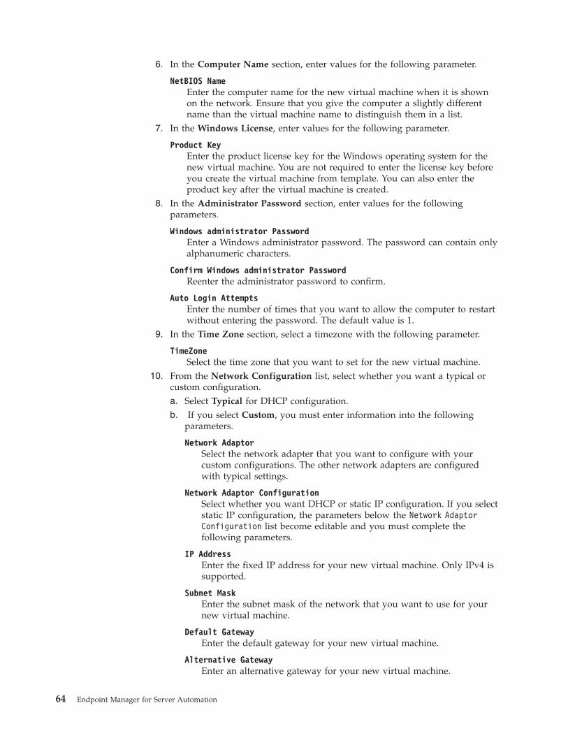
6. In the Computer Name section, enter values for the following parameter.
NetBIOS NameEnter the computer name for the new virtual machine when it is shownon the network. Ensure that you give the computer a slightly differentname than the virtual machine name to distinguish them in a list.
7. In the Windows License, enter values for the following parameter.
Product KeyEnter the product license key for the Windows operating system for thenew virtual machine. You are not required to enter the license key beforeyou create the virtual machine from template. You can also enter theproduct key after the virtual machine is created.
8. In the Administrator Password section, enter values for the followingparameters.
Windows administrator PasswordEnter a Windows administrator password. The password can contain onlyalphanumeric characters.
Confirm Windows administrator PasswordReenter the administrator password to confirm.
Auto Login AttemptsEnter the number of times that you want to allow the computer to restartwithout entering the password. The default value is 1.
9. In the Time Zone section, select a timezone with the following parameter.
TimeZoneSelect the time zone that you want to set for the new virtual machine.
10. From the Network Configuration list, select whether you want a typical orcustom configuration.a. Select Typical for DHCP configuration.b. If you select Custom, you must enter information into the following
parameters.
Network AdaptorSelect the network adapter that you want to configure with yourcustom configurations. The other network adapters are configuredwith typical settings.
Network Adaptor ConfigurationSelect whether you want DHCP or static IP configuration. If you selectstatic IP configuration, the parameters below the Network AdaptorConfiguration list become editable and you must complete thefollowing parameters.
IP AddressEnter the fixed IP address for your new virtual machine. Only IPv4 issupported.
Subnet MaskEnter the subnet mask of the network that you want to use for yournew virtual machine.
Default GatewayEnter the default gateway for your new virtual machine.
Alternative GatewayEnter an alternative gateway for your new virtual machine.
64 Endpoint Manager for Server Automation
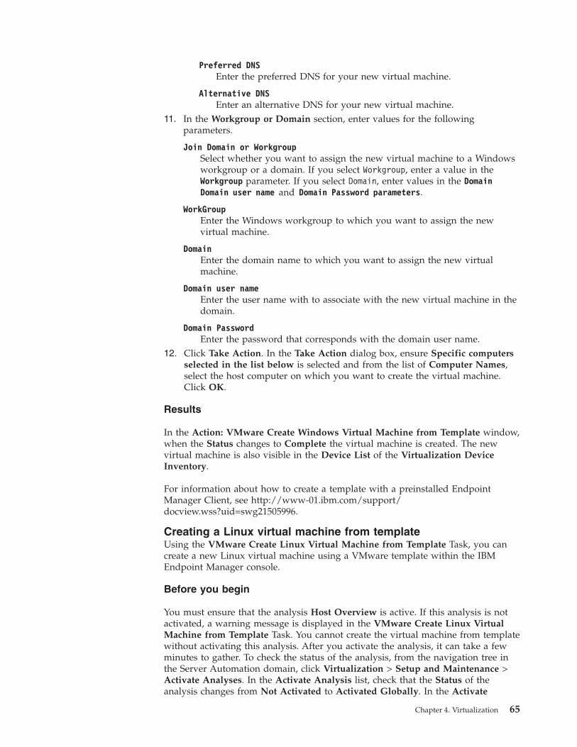
Preferred DNSEnter the preferred DNS for your new virtual machine.
Alternative DNSEnter an alternative DNS for your new virtual machine.
11. In the Workgroup or Domain section, enter values for the followingparameters.
Join Domain or WorkgroupSelect whether you want to assign the new virtual machine to a Windowsworkgroup or a domain. If you select Workgroup, enter a value in theWorkgroup parameter. If you select Domain, enter values in the DomainDomain user name and Domain Password parameters.
WorkGroupEnter the Windows workgroup to which you want to assign the newvirtual machine.
DomainEnter the domain name to which you want to assign the new virtualmachine.
Domain user nameEnter the user name with to associate with the new virtual machine in thedomain.
Domain PasswordEnter the password that corresponds with the domain user name.
12. Click Take Action. In the Take Action dialog box, ensure Specific computersselected in the list below is selected and from the list of Computer Names,select the host computer on which you want to create the virtual machine.Click OK.
Results
In the Action: VMware Create Windows Virtual Machine from Template window,when the Status changes to Complete the virtual machine is created. The newvirtual machine is also visible in the Device List of the Virtualization DeviceInventory.
For information about how to create a template with a preinstalled EndpointManager Client, see http://www-01.ibm.com/support/docview.wss?uid=swg21505996.
Creating a Linux virtual machine from templateUsing the VMware Create Linux Virtual Machine from Template Task, you cancreate a new Linux virtual machine using a VMware template within the IBMEndpoint Manager console.
Before you begin
You must ensure that the analysis Host Overview is active. If this analysis is notactivated, a warning message is displayed in the VMware Create Linux VirtualMachine from Template Task. You cannot create the virtual machine from templatewithout activating this analysis. After you activate the analysis, it can take a fewminutes to gather. To check the status of the analysis, from the navigation tree inthe Server Automation domain, click Virtualization > Setup and Maintenance >Activate Analyses. In the Activate Analysis list, check that the Status of theanalysis changes from Not Activated to Activated Globally. In the Activate
Chapter 4. Virtualization 65

Analysis list, you must select Host Overview and click the Results tab. When theResults window is populated with one or more computer names, the analysis isgathered. If any of the computer names displays the message "not reported", theanalysis is not gathered.
To create a virtual machine from a template, you must install VMware tools on thetemplate that you want to use.
For non-English users: VMware vCenter supports only Simplified Chinese,Japanese, German and French. You can use this Task only if the console languagethat you selected in IBM Endpoint Manager console is identical to the consolelanguage selected in VMware.
If you configured the VMware Management Extender with an ESX host, youcannot use this Task.
About this task
This Task is automatically populated with data from VMware. To work with otherdata, you must turn off validation and enter your own values in the parameterfield. To override the data that is provided in the form, check whether a buttonexists in the Validation column to the left of the parameter that you want todisable and select OFF. For more information, see “Turning off validation in aTask” on page 69.
Complete the following steps to create a Linux virtual machine from template.
Procedure1. Open the Server Automation domain.2. From the navigation tree in the Server Automation domain, click Virtualization
> Host Management > Host Configuration to open the list of HostConfiguration Tasks.
3. From the Host Configuration list, select the VMware Create Linux VirtualMachine from Template Task. To create a virtual machine from a template, youmust complete the following parameters in the Task: VMware Create LinuxVirtual Machine from Template window. If you are working with a copiedTask, click Take Action and enter the required information when you areprompted by the alert boxes.
Table 17. Create Linux Virtual Machine from Template parameters
Parametername Description
Hostcontaining theTemplate
Select the host that contains the template that you want to use to create avirtual machine.
Template Select the name of the template that you want to use to create a virtualmachine. If the template that you want to work with is not listed, selectOFF on the button in the Validation column and enter the name of thetemplate that you want to use. You must ensure that the template namethat you enter is correct.
VMware ToolsInstalled
You can view whether or not VMware tools is installed. You can onlycreate virtual machines from templates which have VMware toolsinstalled.
66 Endpoint Manager for Server Automation
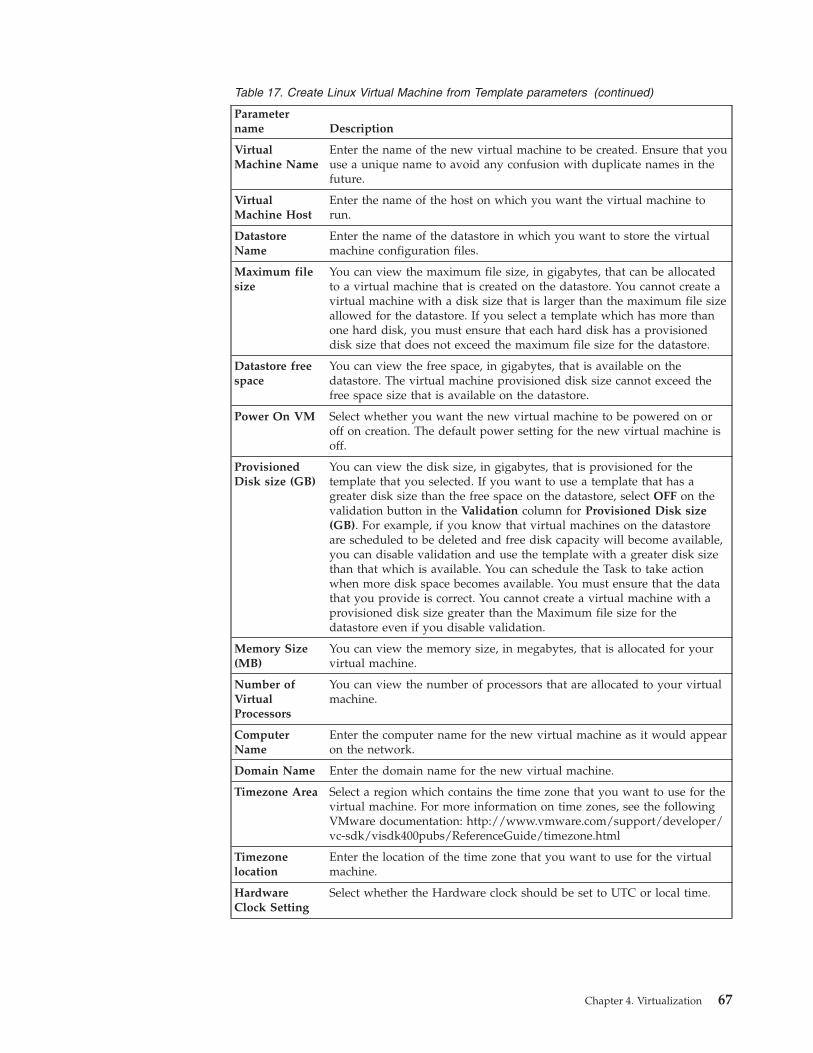
Table 17. Create Linux Virtual Machine from Template parameters (continued)
Parametername Description
VirtualMachine Name
Enter the name of the new virtual machine to be created. Ensure that youuse a unique name to avoid any confusion with duplicate names in thefuture.
VirtualMachine Host
Enter the name of the host on which you want the virtual machine torun.
DatastoreName
Enter the name of the datastore in which you want to store the virtualmachine configuration files.
Maximum filesize
You can view the maximum file size, in gigabytes, that can be allocatedto a virtual machine that is created on the datastore. You cannot create avirtual machine with a disk size that is larger than the maximum file sizeallowed for the datastore. If you select a template which has more thanone hard disk, you must ensure that each hard disk has a provisioneddisk size that does not exceed the maximum file size for the datastore.
Datastore freespace
You can view the free space, in gigabytes, that is available on thedatastore. The virtual machine provisioned disk size cannot exceed thefree space size that is available on the datastore.
Power On VM Select whether you want the new virtual machine to be powered on oroff on creation. The default power setting for the new virtual machine isoff.
ProvisionedDisk size (GB)
You can view the disk size, in gigabytes, that is provisioned for thetemplate that you selected. If you want to use a template that has agreater disk size than the free space on the datastore, select OFF on thevalidation button in the Validation column for Provisioned Disk size(GB). For example, if you know that virtual machines on the datastoreare scheduled to be deleted and free disk capacity will become available,you can disable validation and use the template with a greater disk sizethan that which is available. You can schedule the Task to take actionwhen more disk space becomes available. You must ensure that the datathat you provide is correct. You cannot create a virtual machine with aprovisioned disk size greater than the Maximum file size for thedatastore even if you disable validation.
Memory Size(MB)
You can view the memory size, in megabytes, that is allocated for yourvirtual machine.
Number ofVirtualProcessors
You can view the number of processors that are allocated to your virtualmachine.
ComputerName
Enter the computer name for the new virtual machine as it would appearon the network.
Domain Name Enter the domain name for the new virtual machine.
Timezone Area Select a region which contains the time zone that you want to use for thevirtual machine. For more information on time zones, see the followingVMware documentation: http://www.vmware.com/support/developer/vc-sdk/visdk400pubs/ReferenceGuide/timezone.html
Timezonelocation
Enter the location of the time zone that you want to use for the virtualmachine.
HardwareClock Setting
Select whether the Hardware clock should be set to UTC or local time.
Chapter 4. Virtualization 67
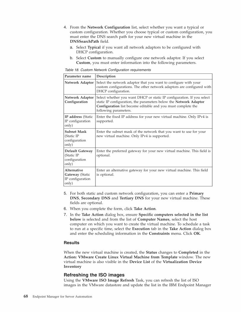
4. From the Network Configuration list, select whether you want a typical orcustom configuration. Whether you choose typical or custom configuration, youmust enter the DNS search path for your new virtual machine in theDNSSearchPath field.a. Select Typical if you want all network adaptors to be configured with
DHCP configuration.b. Select Custom to manually configure one network adaptor. If you select
Custom, you must enter information into the following parameters.
Table 18. Custom Network Configuration requirements
Parameter name Description
Network Adaptor Select the network adaptor that you want to configure with yourcustom configurations. The other network adaptors are configured withDHCP configuration.
Network AdaptorConfiguration
Select whether you want DHCP or static IP configuration. If you selectstatic IP configuration, the parameters below the Network AdaptorConfiguration list become editable and you must complete thefollowing parameters.
IP address (StaticIP configurationonly)
Enter the fixed IP address for your new virtual machine. Only IPv4 issupported.
Subnet Mask(Static IPconfigurationonly)
Enter the subnet mask of the network that you want to use for yournew virtual machine. Only IPv4 is supported.
Default Gateway(Static IPconfigurationonly)
Enter the preferred gateway for your new virtual machine. This field isoptional.
AlternativeGateway (StaticIP configurationonly)
Enter an alternative gateway for your new virtual machine. This fieldis optional.
5. For both static and custom network configuration, you can enter a PrimaryDNS, Secondary DNS and Tertiary DNS for your new virtual machine. Thesefields are optional.
6. When you complete the form, click Take Action.7. In the Take Action dialog box, ensure Specific computers selected in the list
below is selected and from the list of Computer Names, select the hostcomputer on which you want to create the virtual machine. To schedule a taskto run at a specific time, select the Execution tab in the Take Action dialog boxand enter the scheduling information in the Constraints menu. Click OK.
Results
When the new virtual machine is created, the Status changes to Completed in theAction: VMware Create Linux Virtual Machine from Template window. The newvirtual machine is also visible in the Device List of the Virtualization DeviceInventory
Refreshing the ISO imagesUsing the VMware ISO Image Refresh Task, you can refresh the list of ISOimages in the VMware datastore and update the list in the IBM Endpoint Manager
68 Endpoint Manager for Server Automation
console. You can work with your ISO images in IBM Endpoint Manager consolefaster than having to wait for an automatic refresh which occurs every 24 hours.
Before you begin
You must ensure that the analysis Host Overview is active. If this analysis is notactivated, a warning message is displayed in the VMware ISO Image RefreshTask. You cannot proceed without activating the analysis Host Overview. Afteryou activate the analysis, it can take a few minutes to gather. To check the status ofthe analysis, from the navigation tree in the Domain Panel, click Virtualization >Setup and Maintenance > Activate Analyses. In the Activate Analysis list, ensurethat the Status changes from Not Activated to Activated Globally. From theActivate Analysis list, select the Host Overview analysis. In the Analysis:VMware Host Overview window, click the Results tab. When the Results windowis populated with one or more computer names, the analysis is activated. If any ofthe computer names displays the message "not reported", the analysis is notgathered.
This Task refreshes the ISO images list from a single datastore. You must run thisTask on every datastore that has ISO images that you want to view.
For non-English users: VMware vCenter supports only Simplified Chinese,Japanese, German and French. You can use this Task only if the console languagethat you selected in IBM Endpoint Manager console is identical to the consolelanguage selected in VMware.
About this task
Complete the following steps to refresh ISO images in a datastore.
Procedure1. Open the Server Automation domain.2. From the navigation tree in the Server Automation domain, click Virtualization
> Host Management > Host Configuration.3. From the Host Configuration list, select the VMware ISO Image Refresh Task.4. In the Task: VMware ISO Images Refresh window, select the Host and
Datastore name that contains the list of ISO files that you want to refresh isstored and click Take Action.
5. In the Take Action dialog box, target the host on which your ISO images arestored and click OK.
Results
When the list of ISO images is refreshed and the updated list of ISO images isavailable in the IBM Endpoint Manager console, the Status changes to Complete inthe Action: VMware ISO Images Refresh window.
Turning off validation in a TaskSome of the Host management Tasks within the Server Automation domaincontain a Validation button which you can use to disable validation and enter yourown data for some of the parameters.
The Host management Tasks in the Server Automation domain contain formswhich are automatically populated with data from VMware which you mustcomplete to take action. However, on occasion, the data can either be out of date,
Chapter 4. Virtualization 69
or you might need to work with data that does not currently exist but is scheduledto exist at a specific time in the future. If you must work with data that is notpopulated within the Task, you can disable validation.
You can check whether you can disable validation in the Validation column in theTask. If there is an ON/OFF button in the Validation column for the parameter thatyou want to work with, you can select OFF to disable validation. For example, ifyou want to modify a virtual machine that is powered on but is scheduled to bepowered off, you can select OFF on the button in the Validation column for PowerState and schedule the Task to take action when the virtual machine is poweredoff.
For some parameters, you can both disable validation and enter your own values.For example, if you want to modify a virtual machine that is not in the VirtualMachine Name list because it does not exist, but is scheduled to be created, youcan select OFF on the button in the Validation column and enter the name of thevirtual machine that you want to modify.
Disable validation only if you can ensure that your data is correct. When youdisable validation on a parameter and take action, the IBM Endpoint Managerconsole does not verify whether the parameter contains valid data. If invalid datais used, the Task fails in VMware.
If you disable validation for a parameter, other parameters which are dependenton that parameter might be affected. For example, in the VMware Modify VirtualMachine Task, if you disable the Virtual Machine Name parameter, the PowerState and the Disk size parameters are also disabled. The validation on theseparameters is disabled because the IBM Endpoint Manager console cannot validatethe power state or the disk size of a virtual machine that is not listed.
Converting a virtual machine to a templateUsing the VMware Convert Virtual Machine to Template Task, you can convert aVMware virtual machine to a template from the IBM Endpoint Manager console.
Before you begin
Ensure that the analysis VMware Host Overview is active. If this analysis must beactivated, a warning message is displayed in the VMware Convert VirtualMachine to Template Task. You cannot proceed without activating the analysis.Activating the analysis can take a few minutes.
To check the status of the analysis, from the navigation tree in the ServerAutomation domain, click Virtualization > Setup and Maintenance > ActivateAnalyses. In the Activate Analyses list, ensure that the VMware Host Overviewanalysis changes from Not Activated to Activated Globally and click the VMwareHost Overview analysis. In the Analysis: VMware Host Overview window, clickthe Results tab. When the Results window is populated with one or morecomputer names, the analysis is gathered. If any of the computer names displaythe message "not reported", the analysis is not gathered.
For non-English users: VMware vCenter supports only Simplified Chinese,Japanese, German and French. You can use this Task only if the console languagethat you selected in IBM Endpoint Manager console is identical to the consolelanguage selected in VMware.
70 Endpoint Manager for Server Automation
If you configured the VMware Management Extender with an ESX host, youcannot use this Task.
About this task
This Task is automatically populated with data from VMware. To work with otherdata, you must turn off validation and enter your own values into the parameterfield. To override the data that is provided in the form, check whether a buttonexists in the Validation column to the left of the parameter that you want todisable and select OFF. For more information, see “Turning off validation in aTask” on page 69.
Complete the following steps to convert a virtual machine to a template.
Procedure1. Open the Server Automation domain.2. From the navigation tree in the Server Automation domain, click Virtualization
> Host Management > Host Configuration.3. From the Host Configuration list, select the VMware Convert Virtual Machine
to Template Task. If you are working with a copied Task, click Take Action andenter the required information when you are prompted by the alert boxes.
4. In the Task: VMware Convert Virtual Machine to Template window, from theHost list, select the host on which the virtual machine is running.
5. From the Virtual Machine Name list, select the name of the virtual machinethat you want to convert. If the virtual machine name that you want to convertis displayed more than once in the Virtual Machine Name list, you can verifythat the virtual machine that you select is correct by viewing the VirtualMachine UUID field and the IP Address field. If you want to convert a virtualmachine whose name is not displayed in the Virtual Machine Name list, selectOFF on the validation button for Virtual Machine Name in the Validationcolumn. If you disable validation for the Virtual Machine Name list, theVirtual Machine UUID field is cleared. You must ensure that the virtualmachine name that you enter is correct or the Task fails in VMware. For moreinformation, see Turning off validation in a Task
6. You can use the Power State field to view whether the virtual machine thatyou want to convert is powered on or off. VMware allows you to convert onlyvirtual machines that are powered off. However, if you want to convert avirtual machine that is powered on, but is scheduled to be powered off at alater stage, select OFF on the validation button for Power State in theValidation column. You can then schedule the Task to take action when thevirtual machine is powered off.
7. When the form is completed, click Take Action.8. In the Take Action dialog box, ensure Specific computers selected in the list
below is selected and from the list of Computer Names, select the host onwhich the virtual machine is stored and click OK.
Results
When your virtual machine is converted, the Status changes to Completed in theAction: VMware Convert Virtual Machine to Template window. The newtemplate is visible in the Device List window of the Virtualization DeviceInventory and in the Computers window in the All Content domain.
Chapter 4. Virtualization 71
Cloning a virtual machine to a templateUsing the VMware Clone Virtual Machine to Template Task, you can clone aVMware virtual machine to a template from within the IBM Endpoint Managerconsole.
Before you begin
Ensure that the analysis VMware Host Overview is active. If this analysis must beactivated, a warning message is displayed in the VMware Clone Virtual Machineto Template Task. You cannot proceed without activating the analysis. Activatingthe analysis can take a few minutes.
To check the status of the analysis, from the navigation tree in the ServerAutomation domain, click Virtualization > Setup and Maintenance > ActivateAnalyses. In the Activate Analyses list, ensure that the VMware Host Overviewanalysis changes from Not Activated to Activated Globally and click the VMwareHost Overview analysis. In the Analysis: VMware Host Overview window, clickthe Results tab. When the Results window is populated with one or morecomputer names, the analysis is gathered. If any of the computer names displaythe message "not reported", the analysis is not gathered.
For non English users, VMware vCenter only supports, Simplified Chinese,Japanese, German and French. You can only use this Task if the console languagethat you selected in IBM Endpoint Manager console is identical to the consolelanguage selected in VMware.
For non-English users: VMware vCenter supports only Simplified Chinese,Japanese, German and French. You can use this Task only if the console languagethat you selected in IBM Endpoint Manager console is identical to the consolelanguage selected in VMware.
If you configured the VMware Management Extender with an ESX host, youcannot use this Task.
About this task
This Task is automatically populated with data from VMware. To work with otherdata, you must turn off validation and enter your own values into the parameterfield. To override the data that is provided in the form, check whether a buttonexists in the Validation column to the left of the parameter that you want todisable and select OFF. For more information, see “Turning off validation in aTask” on page 69.
Complete the following steps to clone a virtual machine to a template.
Procedure1. Open the Server Automation domain.2. From the navigation tree in the Server Automation domain, click
Virtualization > Host Management > Host Configuration.3. From the Host Configuration list, select the VMware Clone Virtual Machine
to Template Task. If you are working with a copied Task, click Take Actionand enter the required information when you are prompted by the alert boxes.
4. In the Task: VMware Clone Virtual Machine to Template window, from theVirtual Machine Host list, select the host on which the virtual machine thatyou want to clone is running.
72 Endpoint Manager for Server Automation
5. From the Virtual Machine Name list, select the name of the virtual machinethat you want to clone. If the virtual machine name that you want to clone isdisplayed more than once in the Virtual Machine Name list, you can verifythat the virtual machine that you select is correct by viewing the VirtualMachine UUID field and the IP Address field. If you want to clone a virtualmachine whose name is not displayed in the Virtual Machine Name list,select OFF on the validation button for Virtual Machine Name in theValidation column. If you disable validation for the Virtual Machine Namelist, the validation for the Provisioned Disk size is also disabled and theVirtual Machine UUID field is cleared. You must ensure that the virtualmachine name that you enter is correct or the Task fails in VMware. For moreinformation, see Turning off validation in a Task
6. In the Template Name field, enter the name of the new template.7. From the Template Host list, select a host for the new template.8. From the Datastore Name list, select a datastore for the new template.9. In the Maximum file size field, you can view the maximum file size that can
be allocated to a virtual machine that is created on the datastore. You cannotclone a virtual machine that is larger than the maximum file size allowed forthe datastore. If you select a template which has more than one hard disk, youmust ensure that each hard disk has a provisioned disk size that does notexceed the maximum file size for the datastore.
10. In the Datastore free space field, you can view the free space available on thedatastore. The virtual machine provisioned disk size cannot exceed thefreespace size that is available on the datastore.
11. In the Provisioned Disk size field, you can view the disk space that isallocated to the new template. If you want to clone a virtual machine totemplate that has a greater provisioned disk size than the maximum sizeavailable in the Datastore free space field, select OFF on the validation buttonfor Provisioned Disk size in the Validation column and enter a higher value.For example, if you know that virtual machines on the datastore are scheduledto be deleted and free disk capacity will become available, you can clone anew template that has a disk size greater than the maximum free space that isavailable. You can then schedule the task to run at a time when the greaterdisk size is available. You must ensure that this data is correct or the tasksfails in VMware. You cannot create a virtual machine with a provisioned disksize greater than the Maximum file size for the datastore even if you disablevalidation.
12. When you complete the form, click Take Action.13. In the Take Action dialog box, ensure Specific computers selected in the list
below is selected and from the list of Computer Names, select the host onwhich you want the new template to be created and click OK.
Results
When your virtual machine is cloned, the Status changes to Completed in theAction: VMware Clone Virtual Machine to Template window. The new templateis visible in the Device List window of the Virtualization Device Inventory and inthe Computers window in the All Content domain.
Snapshot management tasks
Using these tasks you can create and manage VMware snapshots from the IBMEndpoint Manager console.
Chapter 4. Virtualization 73
Creating a snapshotUsing the Create Snapshot Task, you can create a snapshot of a virtual machinefrom within the IBM Endpoint Manager console. Creating a snapshot captures animage of a virtual machine at a certain time. This snapshot can contain the disk,memory, and device state of a virtual machine at the time of creation.
Before you begin
Ensure that each snapshot that you create has a unique name.
About this task
Complete the following steps to create a snapshot.
Procedure1. Open the Server Automation domain.2. From the navigation tree in the Server Automation domain, click Virtualization
> Virtual Machine Management > Snapshot Configuration.3. From the Snapshot Configuration list, select Create Snapshot.4. In the Task: Create a Snapshot window, click Take Action.5. In the Action Parameter window, enter the name that you want to give your
snapshot and click OK. Ensure that you give the snapshot a unique name.6. From the Computer Name list, select the virtual machine of which you want to
create a snapshot.
Results
When you successfully create a snapshot of a virtual machine, the Status changesto Completed in the Action: Create Snapshot window.
Renaming a snapshotUsing the Rename Snapshot Task, you can rename a snapshot of a virtual machinefrom the IBM Endpoint Manager console.
Before you begin
You must have at least one snapshot of a VMware virtual machine.
About this task
Complete the following steps to rename a snapshot.
Procedure1. Open the Automation domain.2. From the navigation tree in the Automation domain, click Virtualization >
Virtual Machine Management > Snapshot Configuration.3. From the Snapshot Configuration list, select Rename Snapshot.4. In the Task: Rename Snapshot window, click Take Action.5. In the Action Parameter window, enter the name of the snapshot that you want
to rename and click OK.6. In the Action Parameter window, enter the new snapshot name and click OK.7. From the Computer Name list, target the virtual machine of which the
snapshot was taken and click OK
74 Endpoint Manager for Server Automation
Results
When the snapshot is renamed, the Status changes to Completed in the Action:Rename Snapshot window.
Removing a snapshotUsing the Remove Snapshot Task, you can remove an individual snapshot of avirtual machine. This Task does not support the removal of hierarchical snapshots.
Before you begin
You must have at least one snapshot of a virtual machine.
About this task
Complete the following steps to remove a snapshot.
Procedure1. Open the Server Automation domain.2. From the navigation tree in the Server Automation domain, click Virtualization
> Virtual Machine Management > Snapshot Configuration.3. From the Snapshot Configuration list, select Remove Snapshot.4. In the Task: Remove Snapshot window, click Take Action.5. In the Action Parameter window, enter the name of the snapshot that you want
to remove and click OK.6. From the Computer Name list, select the computer of which the snapshot is
taken and click OK.
Results
When the snapshot is removed, the Status changes to Completed in the Action:Remove Snapshot window.
Removing all snapshotsUsing the Remove All Snapshots Task, you can remove all the snapshots of avirtual machine from the IBM Endpoint Manager console.
Before you begin
You must have one or more existing snapshots of a virtual machine.
About this task
Complete the following steps to remove all snapshots of a virtual machine.
Procedure1. Open the Server Automation domain.2. From the navigation tree in the Server Automation domain, click Virtualization
> Virtual Machine Management > Snapshot Configuration.3. From the Snapshot Configuration list, select Remove All Snapshots.4. In the Task: Remove All Snapshots window, click Take Action.5. In the Take Action dialog box, target the computer of which the snapshots
were created and click OK.
Chapter 4. Virtualization 75
Results
When the snapshots are removed, the Status changes to Completed in the Action:Remove All Snapshots window.
Go to SnapshotUsing the Go To Snapshot Task, you can go to a user-defined snapshot of aVMware virtual machine from within the IBM Endpoint Manager console.
Before you begin
You must have one or more existing snapshots for the VMware virtual machine touse this Task.
About this task
Complete the following steps to go to a snapshot.
Procedure1. Open the Server Automation domain.2. From the navigation tree in the Server Automation domain, click Virtualization
> Virtual Machine Management > Snapshot Configuration.3. From the Snapshot Configuration list, select Go To Snapshot.4. In the Action Parameter window, enter the name of the snapshot that you want
to go to and click OK.5. In the Take Action dialog box, target the computer of which the snapshot that
you want to work with was created and click OK.
Results
When you successfully move to a different snapshot, the Status changes toCompleted in the Action: Go To Snapshot window.
Reverting a SnapshotUsing the Revert Snapshot Task, you can revert to the current snapshot of theVMware virtual machine from the IBM Endpoint Manager console.
Before you begin
You must have at least one snapshot of the VMware virtual machine.
This Task does not create a snapshot before it reverts to the original snapshot of aVMware virtual machine.
About this task
Complete the following steps to revert a snapshot.
Procedure1. Open the Server Automation domain2. From the navigation tree in the Server Automation domain, click Virtualization
> Virtual Machine Management > Snapshot Configuration.3. From the Snapshot Configuration list, select Revert Snapshot.
76 Endpoint Manager for Server Automation
4. In the Take Action dialog box, target the computer of which the snapshot iscreated and click OK.
Results
When the snapshot is reverted, the Status changes to Completed in the Action:Revert Snapshot window.
Power management tasksUsing these tasks you can manage the power state of your VMware virtualmachines. Using VMware, you can power off, suspend, and restart your virtualmachines in two different ways: soft and hard. When you perform a poweroperation on a virtual machine with VMware Tools that are installed on the virtualmachine, it is referred to as soft. When you perform a power operation byimmediately stopping the virtual machine, it is referred to as hard. You canperform both hard and soft power operations on VMware virtual machines fromwithin the IBM Endpoint Manager console.
Powering on a VMware virtual machineUsing the Power On VM Task, you can power on VMware virtual machines fromthe IBM Endpoint Manager console.
About this task
Complete the following steps to power on a VMware virtual machine.
Procedure1. Open the Server Automation domain.2. From the navigation tree in the Server Automation domain, click Virtualization
> Virtual Machine Management > Power Configuration.3. From the Power Configuration list, select Power On VM.4. In the Task: Power On VM window, click Take Action.5. In the Take Action dialog box, ensure Specific computers selected in the list
below is selected.6. From the Computer Name list, select the virtual machine that you want to
power on and click OK.
Results
When you successfully power on the virtual machine, the status changes toCompleted in the Action: VMware Power On Virtual Machine window.
Powering off a VMware virtual machine (hard)Using VMware, you can power off your virtual machines in two different ways:power off (soft) and power off (hard). When a virtual machine is powered offusing VMware tools that are installed on the virtual machine, it is referred to inVMware as power off (soft). When a virtual machine is powered off byimmediately stopping it, it is referred to in VMware as a power off (hard). You canpower off VMware virtual machines from within the IBM Endpoint Managerconsole.
About this task
Complete the following steps to power off a virtual machine (hard).
Chapter 4. Virtualization 77
Procedure1. Open the Server Automation domain.2. From the navigation tree in the Server Automation domain, click Virtualization
> Virtual Machine Management > Power Configuration to open the list ofPower Configuration Tasks.
3. From the Power Configuration list, select Power Off VM (hard).4. In the Task: Power Off VM (hard) window, click Take Action.5. In the Take Action dialog box, ensure Specific computers selected in the list
below is selected.6. To target a virtual machine to power off, select a virtual machine from the
Computer Name list and click OK.
Results
When the virtual machine is powered off, the Status changes to Completed in theAction: Power Off VM (hard) window.
Powering off a VMware virtual machine (soft)Using VMware, you can power off your virtual machines in two different ways:power off (soft) and power off (hard). When you power off a virtual machine withVMware tools that are installed on the virtual machine, it is referred to as poweroff (soft). When a virtual machine is powered off by immediately stopping it, it isreferred to as a power off (hard). You can perform both hard and soft power offoperations on VMware virtual machines from within the IBM Endpoint Managerconsole.
Before you begin
To power off (soft) a virtual machine, you must have VMware tools installed onthe guest operating system of the virtual machine.
About this task
Complete the following steps to power off a VMware virtual machine (soft).
Procedure1. Open the Server Automation domain.2. From the navigation tree in the Server Automation domain, click Virtualization
> Virtual Machine Management > Power Configuration to open the list ofPower Configuration Tasks.
3. From the Powe Configuration list, select the Power Off VM (soft) Task.4. In the Task: Power Off VM (soft) window, click Take Action.5. In the Take Action dialog box, ensure Specific computers selected in the list
below is selected.6. To target a virtual machine to power off, select a virtual machine from the
Computer Name list and click OK.
Results
When the virtual machine is powered off, the Status changes to Completed in theAction: Power Off VM (soft) window.
78 Endpoint Manager for Server Automation
Restarting a VMware virtual machine (hard)Using VMware, you can restart your virtual machines in two different ways:restart (soft) and restart (hard). When you restart a virtual machine with VMwaretools that are installed on the virtual machine, it is referred to in VMware as restart(soft). When you restart a virtual machine by immediately restarting it, it isreferred to in VMware as a restart (hard). You can perform both hard and softrestart operations on VMware virtual machines from the IBM Endpoint Managerconsole.
About this task
Complete the following steps to restart a virtual machine (hard).
Procedure1. Open the Server Automation domain.2. From the navigation tree in the Server Automation domain, click Virtualization
> Virtual Machine Management > Power Configuration to open the list ofPower Configuration Tasks.
3. From the Power Configuration list, select Restart VM (hard).4. In the Task: Restart VM (hard) window, click Take Action.5. In the Take Action dialog box, ensure Specific computers selected in the list
below is selected.6. To target a virtual machine to restart, select a virtual machine from the
Computer Name list and click OK.
Results
When the virtual machine is restarted the Status changes to Completed in theAction: Restart VM (hard) window.
Restarting a VMware virtual machine (soft)Using VMware, you can restart your virtual machines in two different ways:restart (soft) and restart (hard). When you restart a virtual machine with VMwaretools that are installed on the virtual machine, it is referred to as restart (soft).When you restart a virtual machine by immediately restarting it, it is referred to asa restart (hard). You can perform both hard and soft restart operations on VMwarevirtual machines from the IBM Endpoint Manager console.
Before you begin
To restart (soft) a virtual machine, you must have VMware tools installed on theguest operating system of the virtual machine.
About this task
Complete the following steps to restart a VMware virtual machine (soft)
Procedure1. Open the Server Automation domain.2. From the navigation tree in the Server Automation domain, click Virtualization
> Virtual Machine Management > Power Configuration to open the list ofPower Configuration Tasks.
3. From the Power Configuration list, select Restart VM (soft).
Chapter 4. Virtualization 79
4. In the Task: Restart VM (soft) window, click Take Action.5. In the Take Action dialog box, ensure Specific computers selected in the list
below is selected.6. To target a virtual machine to restart, select a virtual machine from the
Computer Name list and click OK.
Results
When the virtual machine is restarted, the Status changes to Completed in theAction: Restart VM (soft) window.
Suspending a VMware virtual machine (hard)Using VMware, you can suspend your virtual machines in two different ways:suspend (soft) and suspend (hard). When you suspend a virtual machine withVMware tools that are installed on the virtual machine, it is referred to in VMwareas suspend (soft). When you suspend a virtual machine by immediatelysuspending it, it is referred to in VMware as a suspend (hard). You can performboth hard and soft suspend operations on VMware virtual machines from the IBMEndpoint Manager console.
About this task
Complete the following steps to suspend a VMware virtual machine (hard).
Procedure1. Open the Server Automation domain.2. From the navigation tree in the Server Automation domain, click Virtualization
> Virtual Machine Management > Power Configuration to open the list ofPower Configuration Tasks.
3. From the Tasks list, select Suspend VM (hard).4. In the Task: Suspend VM (hard) window, click Take Action.5. In the Take Action dialog box, ensure Specific computers selected in the list
below is selected.6. To target a virtual machine to suspend, select a virtual machine from the
Computer Name list and click OK.
Results
When the virtual machine is suspended, the Status changes to Completed in theAction: Suspend VM (hard) window.
Suspending a VMware virtual machine (soft)Using VMware, you can suspend your virtual machines in two different ways:suspend (soft) and suspend (hard). When you suspend a virtual machine withVMware tools that are installed on the VMware virtual machine, it is referred to inVMware as suspend (soft). When you suspend a virtual machine by immediatelysuspending it, it is referred to in VMware as a suspend (hard). You can performboth hard and soft suspend operations on VMware virtual machines from the IBMEndpoint Manager console.
Before you begin
To suspend (soft) a virtual machine, you must have VMware tools installed on theguest operating system of the virtual machine.
80 Endpoint Manager for Server Automation
About this task
Complete the following steps to suspend a VMware virtual machine (soft)
Procedure1. Open the Server Automation domain.2. From the navigation tree in the Server Automation domain, click Virtualization
> Virtual Machine Management > Power Configuration to open the list ofPower Configuration Tasks.
3. From the Power Configuration list, select Suspend VM (soft).4. In the Task: Suspend VM (soft) window, click Take Action.5. In the Take Action dialog box, ensure Specific computers selected in the list
below is selected.6. To target a virtual machine to suspend, select a virtual machine from the
Computer Name list and click OK.
Results
When the virtual machine is suspended, the status changes to Completed in theAction: Suspend VM (soft) window.
AIX NIMYou can setup and configure management extender plug-in for AIX NIM. You canthen create and remove NIM Clients and Mksysb images on a NIM master serverfrom within the IBM Endpoint Management console.
Setup and MaintenanceUse the information in this section for instructions and important informationabout how to set up the virtualization environment for AIX NIM.
Before you begin the setup, you must activate the Management Extender Statusanalysis. To activate the analysis, navigate to the Domain Panel of the ServerAutomation domain and select Virtualization > Management Extender Analyses.In the Management Extender Analyses list, select Management Extender Statusand click Activate.
To use the AIX NIM tasks, you must activate the AIX NIM Overview analysis. Toactivate the analysis, in the Domain Panel of the Server Automation domain, select> Virtualization > AIX NIM > Setup and Configuration > Activate Analyses.Select AIX NIM Overview and click Activate. It is good practise to activate theanalysis before you begin to work with the AIX NIM tasks.
Deploying an AIX NIM management extenderUsing the Deploy Management Extender for AIX NIM task, you can deploy themanagement extender plug-in for AIX NIM.
Before you begin
Important: Before you install the management extender plug-in, you must installthe latest version of the proxy agent with a separate Fixlet®. In the BES Supportsite, run the latest version of the Install Proxy Agent Fixlet to install the proxyagent.
Chapter 4. Virtualization 81
You must activate the following analysis:v Management Extender Status
To activate the analysis, navigate to the Domain Panel of the Server Automationdomain and select Virtualization > Management Extender Analyses. In theManagement Extender Analyses list, select Management Extender Status andclick Activate.
About this task
If you want to create or remove NIM Clients, netboot logical partitions (LPARs), orcreate a Mksysb image, you must deploy and configure the management extenderplug-in for AIX NIM.
Procedure1. Open the Server Automation domain.2. In the Domain Panel of the Server Automation domain, select Virtualization >
> AIX NIM > Setup and Maintenance > Deploy AIX NIM Components andselect the Deploy Management Extender for AIX NIM task.
3. From the Management Extender Host list, select the host on which you wantto deploy the management extender.
4. In the Management Extender Plug-in Name field, enter a name for the AIXNIM management extender that is 32 characters or less. You cannot create aname with the following characters *?<>\/:| or enter spaces. You must enter aunique name for every plug-in that you deploy to the IBM Endpoint Managerserver.
5. Click Take action. In the Take Action dialog box, select the managementextender host on which you want to deploy a management extender plug-in forAIX NIM and click OK.
Results
In the Action: Management Extender for AIX NIM window, you can view theprogress of the action. When the Status changes to Complete, the managementextender plug-in for AIX NIM is deployed.
Configuring an AIX NIM management extenderUsing the Configure Management Extender for AIX NIM task, you can configurea management extender plug-in for AIX NIM.
Before you begin
To configure the management extender plug-in with an AIX NIM system, youmust use the root credentials.
You must activate the following analysis:v Management Extender Status
To activate the analysis, navigate to the Domain Panel of the Server Automationdomain and select Virtualization > Management Extender Analyses. In theManagement Extender Analyses list, select Management Extender Status andclick Activate.
82 Endpoint Manager for Server Automation
Procedure1. Open the Server Automation domain.2. In the Domain Panel of the Server Automation domain, select Virtualization >
Setup and Maintenance > AIX NIM > Configure Management Extender andselect the Configure Management Extender for AIX NIM task.
3. In the Connection Details section, enter values for the following parameters
Management Extender HostSelect the host that contains the management extender that you want toconfigure with an AIX NIM system.
Filter AIX NIM Plug-insSelect whether you want to filter the list to display only unconfiguredmanagement extender plug-ins.
Management Extender NameSelect the management extender that you want to configure with an AIXNIM system.
Discovery refresh intervalEnter the frequency, in minutes, in which a full discovery is performed. Youmust enter a frequency of 45 minutes or longer.
NIM ServerEnter the IP address or DNS name of the NIM server with which you wantto configure the management extender. The default SSH port is 22. Tocontrol which SSH port is used to contact the server, add a colon to the endof the IP address or DNS name and enter the port number. Valid portnumbers are 1 - 65534. To override the validation that is provided on theparameter, select OFF in the Validation column to the left of the parameter.For more information, see “Turning off validation in a Task” on page 69.
NIM User NameEnter the user name with which you want to connect to the NIM server.You must use the root credentials to configure the management extenderplug-in with a NIM server.
NIM PasswordEnter the password that corresponds with the user name that you entered.
4. In the Command Execution Options section, if the NIM user name that youentered does not have the permissions to run scripts on the NIM server, enteryour root credentials to the following parameters.
Enable SUSelect whether you want to enter a root password to run all scripts on theNIM server with SU. If the user name and password that you enteredabove cannot connect to the NIM with SSH, you must select True to enableSU. If you select True, you can enter a root password in the Root Passwordfield.
Root PasswordEnter the root password for the NIM server.
Confirm Root PasswordEnter the root password again to confirm.
5. Click Take Action. In the Take Action dialog box, select the IBM EndpointManager server on which the management extender that you want to configureis located
Chapter 4. Virtualization 83
Results
In the Action: Configure Management Extender for AIX NIM window, you canview the progress of the action. When the Status changes to Complete, themanagement extender plug-in is configured with the AIX NIM system.
Note: If this task fails to complete, check the log files. If the log file containsinformation about the corruption of the signed XML, or a mismatch between thestored checksum and the script checksum, you must remove and redeploy themanagement extender.
Upgrading an AIX NIM management extenderUsing the Upgrade Management Extender for AIX NIM Plugin task, you canupgrade a management extender plug-in for AIX NIM.
Before you begin
Important: You cannot use this task to upgrade the proxy agent. You mustupgrade the proxy agent with a separate Fixlet. In the BES Support site, run thelatest version of the Update Windows Proxy Agent Fixlet to upgrade the proxyagent.
Before you can run the Upgrade Management Extender for AIX NIM Plugin task,you must configure the management extender that you want to upgrade.
You must activate the following analysis:v Management Extender Status
To activate the analysis, navigate to the Domain Panel of the Server Automationdomain and select Virtualization > Management Extender Analyses. In theManagement Extender Analyses list, select Management Extender Status andclick Activate.
Procedure1. Open the Server Automation domain.2. In the Domain Panel of the Server Automation domain, select Virtualization >
AIX NIM > Setup and Maintenance > Upgrade AIX NIM Components andselect the Upgrade Management Extender for AIX NIM Plugin task.
3. From the Management Extender Host list, select the IBM Endpoint Managerserver on which the management extender plug-in that you want to upgrade islocated.
4. From the Management Extender Name list, select the management extenderthat you want to upgrade.
5. Click Take Action. In the Take Action dialog box, select the IBM EndpointManager server on which the management extender that you want to upgradeis located.
Results
In the Action: Upgrade Management Extender for AIX NIM Plugin window, youcan view the progress of the action. When the Status changes to Complete, themanagement extender plug-in is upgraded.
84 Endpoint Manager for Server Automation

Removing an AIX NIM management extenderUsing the Remove Management Extender for AIX NIM task, you can remove themanagement extender plug-in for AIX NIM.
Before you begin
Important: This task removes the management extender plug-in. The proxy agentis not removed as part of this task. In the BES Support site, run the latest versionof the Uninstall Windows Proxy Agent Fixlet to remove the proxy agent.
You must activate the following analysisv Management Extender Status
To activate the analysis, navigate to the Domain Panel of the Server Automationdomain and select Virtualization > Management Extender Analyses. In theManagement Extender Analyses list, select Management Extender Status andclick Activate.
Procedure1. Open the Server Automation domain.2. In the Domain Panel of the Server Automation domain, select Virtualization >
AIX NIM > Setup and Maintenance > Remove AIX NIM Components andselect the Remove Management Extender for AIX NIM task.
3. From the Management Extender Host list, select the host from which you wantto remove the management extender.
4. From the Management Extender Plug-in Name list, select the managementextender that you want to remove.
5. Click Take Action. In the Take Action dialog box, select the IBM EndpointManager server from which you want to remove the management extenderplug-in and click OK.
Results
In the Action: Remove Management Extender for AIX NIM window, you canview the progress of the action. When the Status changes to Complete, themanagement extender plug-in is removed from the IBM Endpoint Manager server.
AIX NIM TasksUse the following section to find information about how to create and remote NIMClients on a NIM master server. You can also create a Mksysb image on a NIMserver. These tasks are run on the AIX NIM server.
Creating a NIM client for an LPAR on a NIM serverUsing the AIX NIM Create a Client for a Logical Partition (LPAR) on a NIMMaster Server task, you can create a NIM client on a NIM server. The client thatyou create is associated to an operating system image on the NIM server. When anew client is created, the client copies the image and any required startinformation that is defined on the client. When you netboot the LPAR, theoperating system image is deployed to the LPAR at this stage.
Before you begin
You must activate the following analysis:v AIX NIM Overview
Chapter 4. Virtualization 85
To activate the analysis, navigate to the Domain Panel of the Server Automationdomain and select Virtualization > AIX NIM > Setup and Maintenance and selectAIX NIM Overview. In the Analysis: AIX NIM Overview pane, select Activate.
Procedure1. Open the Server Automation domain2. In the Domain Panel, click Virtualization > AIX NIM > NIM Operations and
select the AIX NIM Create a NIM client for a Logical Partition (LPAR) on aNIM Master Server task.
3. From the NIM Server list, select the NIM server on which you want to createa client.
4. In the NIM Client Name field, enter a name by which you want the LPAR tobe known on the NIM client server.
5. In the LPAR Host/DNS Name field, enter a name for the new client. You canenter either a fully qualified DNS host name or a short host name.
6. In the LPAR IP field, enter the IP address that corresponds to the DNS name,or the entry in the host file on the NIM master server.
7. From the PowerVM OS Image Type list, select whether you want to use anLPP Source or a Mksysb image.
8. If you selected LPP Source from the PowerVM OS Image Type list, select theLPP sources that you want to use from the LPP Source list.
9. If you selected Mksysb, from the PowerVM OS Image Type list, select theMksysb image that you want to use from the Mksysb list.
10. Click Take Action, and in the Take Action dialog box, select the NIM serveron which you want to create a NIM client, and click OK.
Results
In the Action: AIX NIM Create a Client for an LPAR on a NIM server window,you can view the progress of the action. When the Status changes to Complete,the NIM client is created.
Creating a Mksysb ImageUsing the AIX NIM Create a mksysb image task, you can create a Mksysb imagefrom a NIM master server. You can then use the Mksysb image to create a NIMclient.
Before you begin
You must activate the following analysis:v AIX NIM Overview
To activate the analysis, navigate to the Domain Panel of the Server Automationdomain and select Virtualization > AIX NIM > Setup and Maintenance and selectAIX NIM Overview. In the Analysis: AIX NIM Overview pane, select Activate.
Procedure1. Open the Server Automation domain.2. In the Domain Panel, select Virtualization > AIX NIM > NIM Operations and
select the AIX NIM Create a mksysb image task.3. From the NIM Server list, select the NIM master server that contains the NIM
client that you want to use.
86 Endpoint Manager for Server Automation
4. From the NIM Client list, select the NIM client that you want to use togenerate a Mksysb image file.
5. In the NIM Client State, you can view the state of the selected NIM client. Tocreate a Mksysb image, ensure that the NIM client state is "Currently running".To override the data that is provided in the form, select OFF in the Validationcolumn to the left of the parameter. For more information, see “Turning offvalidation in a Task” on page 69.
6. In the Image Name field, enter a name for the new Mksysb image. The namecan contain alphanumeric characters and the following special characters:@%._~!#{}-.
7. In the Image Location field, enter a location for the image on the NIM masterserver. The file path can contain alphanumeric characters and the followingspecial characters: @%/,._~!#*^:+=(){}[]-.
8. Click Take Action, select the NIM client server that you want to use togenerate the Mksysb image and click OK.
Results
In the Action: AIX NIM Create a mksysb image window, you can view theprogress of the action. When the Status changes to Complete, the new Mksysbimage is created.
Removing a NIM clientUsing the AIX NIM Remove NIM Client task, you can remove a NIM client froma NIM master server.
Before you begin
You must activate the following analysisv AIX NIM Overview
To activate the analysis, navigate to the Domain Panel of the Server Automationdomain and select Virtualization > AIX NIM > Setup and Maintenance and selectAIX NIM Overview. In the Analysis: AIX NIM Overview pane, select Activate.
Procedure1. Open the Server Automation domain.2. In the Domain Panel, select Virtualization > AIX NIM > NIM Operations and
select the AIX NIM Remove NIM Client task.3. From the NIM Server list, select the NIM master server that contains the NIM
client that you want to remove.4. From the NIM Client Name list, select the NIM client that you want to remove
and click Take Action.5. In the Take Action dialog box, select the NIM master server from which you
want to remove the NIM client and click OK.
Results
In the Action: AIX NIM Remove NIM Client window, you can view the progressof the action. When the Status changes to Complete, the NIM client is removedfrom the NIM master server.
Chapter 4. Virtualization 87
PowerVMYou can deploy and configure a management extender plug-in for PowerVM®. Youcan then manage PowerVM logical partitions (LPARs) from within the IBMEndpoint Management console.
Setup and Maintainence
Before you begin the setup, you must activate the Management Extender Statusanalysis. To activate the analysis, navigate to the Domain Panel of the ServerAutomation domain and select Virtualization > Management Extender Analyses.In the Management Extender Analyses list, select Management Extender Statusand click Activate.
To use the PowerVM tasks, you must activate several analyses. To activate theanalyses, in the Domain Panel of the Server Automation domain, select >Virtualization > PowerVM > Setup and Configuration > Activate Analyses .Select each analysis and click Activate. It is good practise to activate the analysesbefore you begin to work with the PowerVM tasks.
Deploying a PowerVM Management ExtenderUsing the Deploy Management Extender for PowerVM task, you can deploy amanagement extender to an IBM Endpoint Manager server. You can then configurethe Management Extender to communicate with a PowerVM system.
Before you begin
Important: Before you install the management extender plug-in, you must installthe latest version of the proxy agent with a separate Fixlet. In the BES Support site,run the latest version of the Install Proxy Agent Fixlet to install the proxy agent.
You must activate the following analysis:v Management Extender Status
To activate the analysis, navigate to the Domain Panel of the Server Automationdomain and select Virtualization > Management Extender Analyses. In theManagement Extender Analyses list, select Management Extender Status andclick Activate.
Procedure1. Open the Server Automation domain.2. In the Domain Panel, select Virtualization > PowerVM > Setup and
Maintenance > Deploy PowerVM Components and select the DeployManagement Extender for PowerVM task.
3. From the Management Extender Host list, select the host on which you wantto deploy the management extender.
4. In the Management Extender Plugin Name field, enter a name that you wantto associate to this PowerVM managed system plug-in instance. You cannot usethe following characters: *?<>\/:|. The name can be up to 32 characters inlength and cannot include any spaces. You must enter a unique name for anyplug-in deployed to a relay.
5. Click Take Action. In the Take Action dialog box, target the host on which youwant to deploy the management extender and click OK.
88 Endpoint Manager for Server Automation
Results
In the Action: Deploy Management Extender for PowerVM window, you canview the progress of the action. When the Status changes to Complete, themanagement extender for PowerVM is deployed.
What to do next
To work with the management extender plug-in for PowerVM, you must configurethe plug-in with a PowerVM Hardware Management Console. For moreinformation, see “Configuring a PowerVM management extender.”
Configuring a PowerVM management extenderUsing the Configure Management Extender for PowerVM task, you can configurea selected management extender to connect to a Hardware Management Console(HMC). You can use this task also to modify existing management extenderconnections to a PowerVM environment.
Before you begin
Ensure that all managed systems, LPAR, and profile names contain only validcharacters. The management extender cannot discover any resources with namesthat the following special characters: !@#$%^&*()+\=[]{};':"|,.<>\/?~` or spaces.
You must install a management extender for a PowerVM system before you canconfigure a management extender. To install a management extender forPowerVM, use the Deploy Management Extender for PowerVM task. For moreinformation, see “Deploying a PowerVM Management Extender” on page 88
To configure the management extender plug-in with the PowerVM HMC, youmust enter credentials that are part of the HMC Administrator's group.
Ensure that your HMC credentials are valid. You can validate your credentials bylogging in to the HMC servers.
If you enter an HMC IP address, ensure that the address is IPv4. IPv6 is notsupported.
You must activate the following analysis:v Management Extender Status
To activate the analysis, navigate to the Domain Panel of the Server Automationdomain and select Virtualization > Management Extender Analyses. In theManagement Extender Analyses list, select Management Extender Status andclick Activate in the panel.
Procedure1. Open the Server Automation domain.2. In the navigation tree of the Domain Panel, select Virtualization > PowerVM >
Setup and Maintenance > Configure Management Extender and select theConfigure Management Extender for PowerVM task.
3. In the Connection Details section, enter values for the following parameters.
Management Extender HostSelect the host that contains the management extender that you want toconfigure.
Chapter 4. Virtualization 89
Filter PowerVM Plug-insSelect whether you want to filter the list of management extenders todisplay only unconfigured PowerVM management extenders in theManagement Extender Name list.
Management Extender NameSelect the management extender that you want to configure with aPowerVM system.
Discovery refresh intervalSelect the frequency, in minutes, in which a full discovery is performed.You must enter a frequency of 45 minutes or longer.
HMC ServerEnter the IP address or DNS name of the HMC server with which youwant to configure the management extender. The default SSH port is 22. Tocontrol which SSH port is used to contact the server, add a colon (:) to theend of the IP address or DNS name and enter the port number. Valid portnumbers are 1 - 65534.
HMC User NameEnter the user name with which you want to connect to the HMC server.The user name that you enter must be part of the HMC Administrator'sgroup. Valid HMC user names begin with a letter and contain up to 32characters. To override the validation that is provided on the parameter,select OFF in the Validation column to the left of the parameter that youwant to disable. For more information, see “Turning off validation in aTask” on page 69.
HMC passwordEnter the password that corresponds to the HMC user name that youentered. Valid passwords contain at least 7 characters.
Confirm HMC password.Enter the password again to confirm.
4. In the Redundant Connection Details, enter values for the followingparameters. The redundancy model is an 'active standby' model rather than'active active'. The management extender plug-in uses only one HMC server ata time to manage the PowerVM environment.
Enable HMC Connection RedundancySelect whether you want to setup a redundant HMC connection to themanagement extender plug-in. If you select true, you must enter values forthe Redundant HMC Server, Redundant HMC User Name, Redundant HMCPassword, and Confirm Redundant HMC Password parameters.
Redundant HMC ServerEnter the IP address or DNS name of the redundant HMC server withwhich you want to configure the management extender. The default SSHport is 22. To control which SSH port is used to contact the server, add acolon (:) to the end of the IP address or DNS name and enter the portnumber. Valid port numbers are 1 - 65534.
Important: This HMC must be available at the time of configuring.
Redundant HMC User NameEnter the user name with which you want to connect to the redundantHMC server. The user name that you enter must be part of theHMCAdministrator's group. Valid user names begin with a letter andcontain up to 32 characters.
90 Endpoint Manager for Server Automation

Redundant HMC PasswordEnter the password that corresponds to the user name that you entered.Valid passwords contain at least 7 characters.
Confirm Redundant HMC PasswordEnter the password again to confirm.
5. Click Take Action and in the Take Action dialog box, target the host on whichthe management extender that you want to configure is located, and click OK.
Results
In the Action: Configure Management Extender for PowerVM window, you canview the progress of the action. When the Status changes to Complete, themanager extender is configured.
Upgrading a PowerVM management extenderUsing the Upgrade Management Extender for PowerVM Plugin task, you canupgrade the plug-in component of the management extender for PowerVM.
Before you begin
Important: You cannot use this task to upgrade the proxy agent. You mustupgrade the proxy agent with a separate Fixlet. In the BES Support site, run thelatest version of the Update Windows Proxy Agent Fixlet to upgrade the proxyagent.
Before you can run the Upgrade Management Extender for PowerVM Plugin task,you must configure the management extender that you want to upgrade. For moreinformation, see “Configuring a PowerVM management extender” on page 89.
You must activate the following analysis:v Management Extender Status
To activate the analysis, navigate to the Domain Panel of the Server Automationdomain and select Virtualization > Management Extender Analyses. In theManagement Extender Analyses list, select Management Extender Status andclick Activate.
Procedure1. Open the Server Automation domain.2. In Domain Panel, select Virtualization > PowerVM > Setup and Maintenance
> Upgrade PowervM Components.3. From the Upgrade PowervM Components list, select Upgrade Management
Extender for PowerVM Plugin.4. From the Management Extender Host list, select the host on which the
management extender that you want to upgrade is located.5. From the Management Extender Name list, select the management extender
that you want to upgrade and click Take Action.6. In the Take Action dialog box, select the management extender host on which
the management extender that you want to upgrade is located and click OK.
Chapter 4. Virtualization 91
Results
In the Action: Upgrade Management Extender for PowerVM Plugin window, youcan view the progress of the action. When the Status changes to Complete, themanagement extender is upgraded.
Removing a PowerVM management extenderUsing the Remove Management Extender for PowerVM task, you can remove aselected management extender plug-in from an IBM Endpoint Manager server.
Before you begin
Important: You must first remove the management extender plug-in, thenuninstall the proxy agent with a separate Fixlet. In the BES Support site, run thelatest version of the Uninstall Windows Proxy Agent Fixlet to remove the proxyagent.
You must activate the following analysisv Management Extender Status
To activate the analysis, navigate to the Domain Panel of the Server Automationdomain and select Virtualization > Management Extender Analyses. In theManagement Extender Analyses list, select Management Extender Status andclick Activate.
About this task
The Remove Management Extender for PowerVM task removes the managementextender plug-in for PowerVM from the IBM Endpoint Manager server that youtarget.
Procedure1. Open the Server Automation domain.2. In the Domain Panel, select Virtualization > PowerVM > Setup and
Maintenance > Remove PowerVM Components.3. From the Remove PowerVM Components list, select Remove Management
Extender for PowerVM.4. From the Management Extender Host list, select the host on which the
management extender plug-in that you want to remove is located.5. From the Management Extender Name list, select the name of the management
extender that you want to remove.6. Click Take Action. In the Take Action dialog box, target the host from which
you want to remove the management extender plug-in, and click OK.
Results
In the Action: Remove Management Extender for PowerVM window, you canview the progress of the action. When the Status changes to Complete, themanagement extender plug-in is removed.
Managed System TasksUse the information in this section to create and delete logical partitions on aPowerVM Managed System that is configured with a management extender forPowerVM
92 Endpoint Manager for Server Automation
.
Creating a Logical Partition (LPAR)Using the PowerVM Create a logical partition (LPAR) task, you can create a newlogical partition (LPAR) on a PowerVM Managed System.
Before you begin
You must deploy and configure a management extender for PowerVM on an IBMEndpoint Manager server. For more information, see “Deploying a PowerVMManagement Extender” on page 88 and “Configuring a PowerVM managementextender” on page 89.
You must activate the following analyses:v PowerVM HMC Overviewv PowerVM LPAR Overviewv PowerVM Managed System Overviewv PowerVM VIOS Overview
To activate the analyses, navigate to the Domain Panel of the Server Automationdomain and select Virtualization > PowerVM > Setup and Maintenance andselect PowerVM HMC Overview. In the Analysis: PowerVM HMC Overviewpane, select Activate. Repeat this action for the PowerVM Managed SystemOverview, PowerVM LPAR Overview, and PowerVM VIOS Overview analyses.
For information about how to disable validation on certain parameters in the task,see “Turning off validation in a Task” on page 69.
Procedure1. Open the Server Automation domain.2. From the navigation tree in the Server Automation domain, click
Virtualization > PowerVM > Managed System Operations > ConfigurationManagement and select PowerVM Create a logical partition (LPAR).
3. In the Partition section, add the name, ID, and profile details of the newLPAR.
HMCSelect the hardware management console on which you want to create theLPAR.
Managed SystemSelect a PowerVM managed system on which you want to create theLPAR.
Partition NameEnter a name for the new LPAR. Ensure that the name that you enter isunique on the Managed System that you select. To override the validationthat is provided on the parameter, select OFF in the Validation column tothe left of the parameter. For more information, see “Turning offvalidation in a Task” on page 69.
Partition IDEnter an ID for the new LPAR. Ensure that the ID that you enter is uniqueon the Managed System that you select. To override the validation that isprovided on the parameter, in the Validation column to the left of theparameter and select OFF. For more information, see “Turning offvalidation in a Task” on page 69.
Chapter 4. Virtualization 93
Profile NameEnter a profile name for the new LPAR. To override the validation that isprovided on the parameter, select OFF in the Validation column to the leftof the parameter. For more information, see “Turning off validation in aTask” on page 69.
4. From the Processing Mode list, select whether you want to add shared ordedicated processors to the new LPAR. If you select shared, the managedsystem assigns partial processor units from the shared processor pool to thenew LPAR. If you select dedicated, the managed system reserves entirephysical processors that can be used only by the new LPAR.
5. In the Processing Settings section, you can configure the processing settingsfor the new LPAR. From the Processing Mode list, if you select shared, thetask displays the following parameters: Minimum Processing Units, DesiredProcessing Units, and Maximum Processing Units. If you select dedicated,the task removes these parameters. Use the Total Processors available field toview how many processors are available on the managed system that youselected.
Minimum Processing UnitsEnter the minimum number of processing units that you want to use tocreate virtual processors for the new LPAR. Each processing unit isequivalent to the processing power of one processor. You can enter wholenumbers or decimal numbers. For example, 2 or 2.5 processor units can beassigned to the partition.
Desired Processing UnitsEnter the number of processing units that you want to use to createvirtual processors for the new LPAR. Each processing unit is equivalent tothe processing power of one processor. You can enter whole numbers ordecimal numbers. For example, 2 or 2.5 processor units can be assigned tothe partition.
Maximum Processing UnitsEnter the maximum number of physical processors that you want to useto create virtual processors for the new LPAR. Each processing unit isequivalent to the processing power of one processor. You can enter wholenumbers or decimal numbers. For example, 2 or 2.5 processor units can beassigned to the partition.
Minimum Processing Units requiredView the minimum processing units to ensure that you enter valid valuesin the Minimum Processors field.
Minimum ProcessorsEnter the minimum number of processors that you want to assign to thenew LPAR. Enter a value that is greater than the minimum processingunits. If you select Shared, these processors are virtual. If you selectDedicated, these processors are physical.
Desired ProcessorsEnter the number of virtual processors that you want to assign to the newLPAR. If you select Shared, these processors are virtual. If you selectDedicated, these processors are physical.
Maximum ProcessorsEnter the maximum number of virtual processors that you want to assignto the new LPAR. If you select Shared, these processors are virtual. If youselect Dedicated, these processors are physical.
94 Endpoint Manager for Server Automation
6. In the Memory Settings section, enter the memory values for the new LPAR.Use the Installed Memory field and Current Memory Available field todetermine how much memory is available to assign.
Minimum MemorySelect a minimum memory size that you want to set for the selectedLPAR.
Desired MemorySelect a memory size that you want to set for the selected LPAR.
Maximum MemorySelect a maximum memory size that you want to set for the selectedLPAR.
7. In the General Virtual Adapter Settings section, enter the maximum virtualadapter values for the new LPAR.
Maximum Virtual AdaptersEnter the maximum number of virtual adapters that you want to connectto the new LPAR.
8. In the Virtual Ethernet Settings section, enter values for the Ethernetparameters.
Virtual Ethernet Adapter IDEnter the virtual Ethernet adapter ID.
VLANEnter the ID of the (Virtual Local Area Network) VLAN that you want toconfigure with the Ethernet adapter. To override the validation that isprovided on the parameter, select OFF in the Validation column to the leftof the parameter. For more information, see “Turning off validation in aTask” on page 69.
9. In the Storage Settings section, enter the storage values for the new LPAR.From the Storage Type list, select whether you want Virtual Small ComputerSystem Interface (vSCSI) or Node Port ID Virtualization (NPIV) storage type forthe new LPAR.a. If you select vSCSI, enter the following parameters.
vSCSI TypeSelect whether you want to add a Hard Disk or Logical Volume storageto be the root disk of the new LPAR. Depending on your selection, thetask displays different parameters. If you select Hard Disk, you mustenter values for the following parameters: Configure Redundant IO,Hard Disk, parameters. If you select Logical volume, you must enterthe values for the following parameters: Logical Volume Group,Logical Volume Size (GB), and Logical Volume Name.
Client Adapter IDEnter the ID of the LPAR client adapter that you want to use for theroot disk of the new LPAR.
VIO Server PartitionSelect the name of the virtual input/output server (VIOS) to whichyou want to add the adapter to the disk of the new LPAR.
VIO Server Adapter IDEnter the adapter ID of the VIOS that you want to use on the VIOS forthe disk of the new LPAR. To override the validation that is provided
Chapter 4. Virtualization 95

on the parameter, select OFF in the Validation column to the left ofthe parameter. For more information, see “Turning off validation in aTask” on page 69.
Configure Redundant IOSelect whether you want to configure an alternative path for multipath input output (MPIO) redundancy. If you select YES, you mustenter the values for the following parameters: Redundant ClientAdapter ID, Redundant Server Partition, and Redundant ServerAdapter ID. The Hard Disk list is filtered and displays only hard disksthat are configured for MPIO.
Redundant Client Adapter IDEnter the ID of the redundant LPAR client adapter that you want touse for the root disk of the new LPAR.
Redundant Server PartitionSelect the Redundant VIO Server that you want to configure to enablemulti-path for the root disk of the new LPAR.
Redundant Server Adapter IDEnter the redundant VIO server adapter ID that you want to use onthe redundant VIO server for the root disk of the new LPAR.
Hard DiskSelect the physical disk to which you want to attach the vSCSI adapter.Hard disks that are associated to volume groups or LPARs are notlisted. Hard disks without a valid physical volume ID (PVID) are notlisted.
Disk Unique IDView the unique ID of the hard disk that you selected.
Disk DescriptionView the description of the hard disk.
Logical Volume GroupSelect the logical volume group from which you want to create storagefor the new SCSI disk.
Logical Volume Size (GB)Enter the size, in gigabytes, that you want to allocate to the new SCSIdisk.
Logical Volume NameEnter a name for the logical volume.
Device NameEnter a virtual target name that the VIO server associates with thehard disk.
b. If you select NPIV, enter the values for following parameters:
Client Adapter IDEnter the ID of the LPAR client adapter that you want to use for theroot disk of the new LPAR.
VIO Server PartitionSelect the name of the (VIOS) to which you want to add the adapterfor the root disk of the new LPAR.
VIO Server Adapter IDEnter the adapter ID of the VIO server that you want to use on theVIOS for the root disk of the new LPAR.
96 Endpoint Manager for Server Automation
Autogenerate WWPNsSelect whether you want to automatically generate worldwide portnames (WWPN) for the client adapter. The default setting is Yes. If youselect No, you must enter port name in the WWPN 1 and WWPN 2 fields. Ifyou select No and are configuring MPIO, you must also enter theRedundant WWPN 1 and Redundant WWPN 2 fields.
WWPN 1Enter the first WWPN for the client adapter.
WWPN 2Enter the second WWPN for the client adapter.
Primary FC PortSelect the Fibre Channel port that you want to use as the primary port.
Configure Redundant IOSelect whether you want to configure an alternative path formulti-path input/output (MPIO) redundancy. If you select YES, thefollowing parameters become visible: Redundant Client Adapter ID,Redundant Server Partition, Redundant Server Adapter ID, RedundantWWPN 1, Redundant WWPN 2, and Secondary FC Port, .
Redundant Client Adapter IDEnter the unique ID of the redundant LPAR client adapter that youwant to use.
Redundant Server PartitionSelect the name of the redundant server to which you want to add theredundant client adapter ID.
Redundant Server Adapter IDEnter the redundant adapter ID of the Virtual I/O Server that youwant to use.
Redundant WWPN 1Enter the first redundant WWPN for the client adapter.
Redundant WWPN 2Enter the second redundant WWPN for the client adapter.
Secondary FC PortSelect a secondary Fibre Channel port.
10. When you enter all the mandatory parameters, click Take Action.11. In the Take Action dialog box, select the PowerVM managed system on which
you want to create the new LPAR, and click OK.
Results
In the Action: PowerVM Create a logical partition (LPAR) window, you can viewthe progress of the action. When the Status changes to Complete, the new LPAR iscreated. In the Computers list in the All Content domain, you can view the newLPAR. You can distinguish an LPAR from other computers by using the DeviceType column in the Computers list. The Device Type of the new LPAR isPowerVM LPAR.
What to do next
To work with the new LPAR, you must create a client for the LPAR on a NIMserver and then netboot the LPAR. For more information, see “Creating a NIM
Chapter 4. Virtualization 97
client for an LPAR on a NIM server” on page 85 and “Netbooting a logicalpartition” on page 111.
Deleting an LPARUsing the PowerVM Delete a Logical Partition (LPAR) task, you can delete anLPAR from a PowerVM managed system. The LPAR is deleted together with thehard disk, logical volume, physical volume, virtual host, virtual target, vSCSIadapter, Fibre Channel host, and Fibre Channel adapter ID.
Before you begin
You must activate the following analyses:v PowerVM HMC Overviewv PowerVM LPAR Overviewv PowerVM Managed System Overview
To activate the analyses, navigate to the Domain Panel of the Server Automationdomain and select Virtualization > PowerVM > Setup and Maintenance andselect PowerVM HMC Overview. In the Analysis: PowerVM HMC Overviewpane, select Activate. Repeat this action for the PowerVM Managed SystemOverview, and PowerVM LPAR Overview analyses.
For information about how to disable validation on certain parameters in the task,see “Turning off validation in a Task” on page 69.
Procedure1. Open the Server Automation domain.2. From the Domain Panel, select Virtualization > PowerVM > Managed System
Operations > Configuration Management.3. From the Configuration Management list, select PowerVM Delete a Logical
Partition (LPAR).4. From the HMC list, select the Hardware Management Console on which the
LPAR that you want to delete is located.5. From the Managed System list, select the PowerVM managed system on which
the LPAR that you want to delete is located.6. From the LPAR Name list, select the LPAR that you want to delete. To override
the validation that is provided on the parameter, in the Validation column tothe left of the parameter, select OFF. For more information, see “Turning offvalidation in a Task” on page 69.
7. In the LPAR State field, you can view whether the LPAR that you select isrunning or not activated. You cannot delete an LPAR that is running. Tooverride the validation that is provided on the parameter, in the Validationcolumn to the left of the parameter, select OFF. For more information, see“Turning off validation in a Task” on page 69.
8. From the Delete Disk list, select No if you want to delete the LPAR but retainthe Logical Volume. Select Yes if you want to delete LPAR and also the harddisk, logical volume, physical volume, virtual host, virtual target, vSCSIadapter, Fibre Channel host, and Fibre Channel adapter ID.
9. Click Take Action, and in the Take Action dialog box, select the PowerVMmanaged system from which you want to delete an LPAR, and click OK.
98 Endpoint Manager for Server Automation
Results
In the Action: PowerVM Delete a Logical Partition (LPAR) window, you can viewthe progress of the action. When the Status changes to Complete, the LPAR isdeleted.
LPAR TasksUsing these tasks, you can modify, add disks, and create profiles for existinglogical partitions (LPARs).
Creating an LPAR ProfileUsing the PowerVM Create a logical partition (LPAR) Profile task, you can createan LPAR Profile for an existing LPAR from within the IBM Endpoint Managerconsole.
Before you begin
You must activate the following analyses:v PowerVM HMC Overviewv PowerVM LPAR Overviewv PowerVM Managed System Overviewv PowerVM VIOS Overview
To activate the analyses, navigate to the Domain Panel of the Server Automationdomain and select Virtualization > PowerVM > Setup and Maintenance andselect PowerVM HMC Overview. In the Analysis: PowerVM HMC Overviewpane, select Activate. Repeat this action for the PowerVM Managed SystemOverview, PowerVM LPAR Overview, and PowerVM VIOS Overview analyses.
For information about how to disable validation on certain parameters in the task,see “Turning off validation in a Task” on page 69.
Procedure1. Open the Server Automation domain.2. From the Domain Panel, select Virtualization > PowerVM > LPAR
Operations > Configuration Management, and select PowerVM Create alogical partition (LPAR) Profile.
3. In the Partition section, add the name, ID, and profile details of the newLPAR profile.
HMCSelect the Hardware Management Console on which the LPAR that youwant to use is located.
Managed SystemSelect the PowerVM managed system on which the LPAR that you wantto use is located.
Partition NameSelect the LPAR on which you want to create a profile. To override thevalidation that is provided on the parameter, select OFF in the Validationcolumn to the left of the parameter. For more information, see “Turningoff validation in a Task” on page 69.
Profile NameEnter the name of the new profile. To override the validation that is
Chapter 4. Virtualization 99
provided on the parameter, select OFF in the Validation column to the leftof the parameter. For more information, see “Turning off validation in aTask” on page 69.
4. From the Processing Mode list, select whether you want to add shared ordedicated processors to the new LPAR profile. If you select shared, themanaged system assigns partial processor units from the shared processorpool to the new LPAR profile. If you select dedicated, the managed systemreserves entire physical processors that can be used only by the new LPARprofile.
5. In the Processing Settings section, you can configure the processing settingsfor the new LPAR profile. If you select shared from the Processing Mode list,the task displays the following parameters: Minimum Processing Units,Desired Processing Units, and Maximum Processing Units. If you selectdedicated, the task removes these parameters. Use the Total Processorsavailable field to view how many processors are available on the managedsystem that you selected.
Minimum Processing UnitsEnter the minimum number of physical processors that you want to use tocreate virtual processors for the new LPAR profile. Each processing unit isequivalent to the processing power of one processor. You can enter wholenumbers or decimal numbers. For example, 2 or 2.5 processor units can beassigned to the partition.
Desired Processing UnitsEnter the number of physical processors that you want to use to createvirtual processors for the new LPAR profile. Each processing unit isequivalent to the processing power of one processor. You can enter wholenumbers or decimal numbers. For example, 2 or 2.5 processor units can beassigned to the partition.
Maximum Processing UnitsEnter the maximum number of physical processors that you want to useto create virtual processors for the new LPAR profile. Each processing unitis equivalent to the processing power of one processor. You can enterwhole numbers or decimal numbers. For example, 2 or 2.5 processor unitscan be assigned to the partition.
Minimum Processing Units requiredView the minimum processing units to ensure that you enter valid valuesin the Minimum Processors field.
Minimum ProcessorsEnter the minimum number of processors that you want to assign to thenew LPAR profile. Enter a value that is greater than the minimumprocessing unit.
Desired ProcessorsEnter the number of processors that you want to assign to the new LPARprofile.
Maximum ProcessorsEnter the maximum number of processors that you want to assign to thenew LPAR profile.
6. In the Memory Settings section, enter the memory values for the new LPARprofile. Use the Installed Memory field and Current Memory Available fieldto determine how much memory is available to assign.
100 Endpoint Manager for Server Automation
Minimum MemorySelect the minimum memory size that you want to set for the selectedLPAR profile.
Desired MemorySelect the memory size that you want to set for the selected LPAR profile.
Maximum MemorySelect the maximum memory size that you want to set for the selectedLPAR profile.
7. In the General Virtual Adapter Settings section, enter the maximum virtualadapter values for the new LPAR.
Maximum Virtual AdaptersEnter the maximum number of virtual adapters that you want to connectto the new LPAR.
8. In the Virtual Ethernet Settings section, enter values for the parameters in theEthernet settings of the new profile.
Virtual Ethernet Adapter IDEnter the virtual Ethernet adapter ID. To override the validation that isprovided on the parameter, select OFF in the Validation column to the leftof the parameter. For more information, see “Turning off validation in aTask” on page 69.
VLANEnter the ID of the (Virtual Local Area Network) VLAN that you want toconfigure with the Ethernet adapter.
9. In the Storage Settings section, enter the storage values for the new LPAR.From the Storage Type list, select whether you want Virtual Small ComputerSystem Interface (vSCSI) or Node Port ID Virtualization (NPIV) storage for thenew LPAR profile.a. If you select vSCSI, enter the following parameters.
Client Adapter IDEnter the ID of the LPAR client adapter that you want to use for theAIX root disk of the new LPAR. To override the validation that isprovided on the parameter, select OFF in the Validation column to theleft of the parameter. For more information, see “Turning off validationin a Task” on page 69.
VIO Server PartitionSelect the name of the virtual input/output server (VIOS) to whichyou want to add the adapter ID.
Server Adapter IDEnter the adapter ID that you want to use on the VIOS for the rootdisk of the new LPAR. To override the validation that is provided onthe parameter, select OFF in the Validation column to the left of theparameter. For more information, see “Turning off validation in aTask” on page 69.
Configure Redundant IOSelect whether you want to configure an alternative path formulti-path input/output (MPIO) redundancy. If you select YES, youmust enter the values for the following parameters: Redundant ClientAdapter ID, Redundant Server Partition, and Redundant ServerAdapter ID. The Hard Disk list is filtered and displays only hard disksthat are configured for MPIO.
Chapter 4. Virtualization 101
Redundant Client Adapter IDEnter the ID of the redundant LPAR client adapter that you want touse for the root disk of the new LPAR.
Redundant Server PartitionSelect the Redundant VIO Server that you want to configure to enablemulti-path for the root disk of the new LPAR.
Redundant Server Adapter IDEnter the redundant VIO server adapter ID that you want to use onthe redundant VIO server for the root disk of the new LPAR.
b. If you select NPIV, enter the values for following parameters:
Client Adapter IDEnter the ID of the LPAR client adapter that you want to use for theroot disk of the new LPAR.
VIO Server PartitionSelect the name of the (VIOS) to which you want to add the adapterfor the root disk of the new LPAR.
VIO Server Adapter IDEnter the adapter ID that you want to use on the VIOS for the rootdisk of the new LPAR.
Autogenerate WWPNsSelect whether you want to automatically generate worldwide portnames (WWPN) for the client adapter. The default setting is Yes. If youselect No, you must enter port name in the WWPN 1 and WWPN 2 fields. Ifyou select No and you are configuring MPIO, you must also enter theRedundant WWPN 1 and Redundant WWPN 2 fields.
WWPN 1Enter the first WWPN for the client adapter.
WWPN 2Enter the second WWPN for the client adapter.
Configure Redundant IOSelect whether you want to configure an alternative path formulti-path input/output (MPIO) redundancy. If you select YES, thefollowing parameters become visible: Redundant Client Adapter ID,Redundant Server Partition, Redundant Server Adapter ID, RedundantWWPN 1, Redundant WWPN 2.
Redundant Client Adapter IDEnter the unique ID of the redundant LPAR client adapter that youwant to use.
Redundant Server PartitionSelect the name of the redundant server to which you want to add theredundant client adapter ID.
Redundant Server Adapter IDEnter the redundant adapter ID of the Virtual I/O Server that youwant to use.
Redundant WWPN 1Enter the first redundant WWPN for the client adapter.
Redundant WWPN 2Enter the second redundant WWPN for the client adapter.
102 Endpoint Manager for Server Automation
10. Click Take Action, and in the Take Action dialog box, target the LPAR onwhich you want to create a profile, and click OK.
Results
In the Action: Power VM Create LPAR Profile window, you can view the progressof the action. When the Status changes to Complete, the new LPAR profile iscreated.
Modifying an LPAR ProfileUsing the PowerVM Modify a Logical Partition (LPAR) Profile task, you canmodify the profile name, the processing settings, and the memory settings of alogical partition (LPAR) profile.
Before you begin
You must activate the following analysis:v PowerVM HMC Overviewv PowerVM LPAR Overviewv PowerVM Managed System Overview
To activate the analysis, navigate to the Domain Panel of the Server Automationdomain and select Virtualization > PowerVM > Setup and Maintenance andselect PowerVM HMC Overview. In the Analysis: PowerVM HMC Overviewpane, select Activate. Repeat this action for the PowerVM Managed SystemOverview and PowerVM LPAR Overview analyses.
For information about how to disable validation on certain parameters in the task,see “Turning off validation in a Task” on page 69.
Procedure1. Open the Server Automation domain.2. From the Domain Panel, select Virtualization > PowerVM > LPAR Operations
> Configuration Management and select PowerVM Modify a Logical Partition(LPAR) Profile..
3. In the Partition section, select the LPAR that you want to modify and enter anychanges to the following parameters:
HMCSelect the Hardware Management Console on which the LPAR that youwant to modify is located.
Managed SystemSelect the PowerVM managed system on which the LPAR that you want tomodify is located.
Partition NameSelect the name of the LPAR that you want to modify. Use the Partition IDfield to verify that the LPAR that you select is correct. To override thevalidation that is provided on the parameter, select OFF in the Validationcolumn to the left of the parameter. For more information, see “Turning offvalidation in a Task” on page 69.
Profile NameSelect the LPAR Profile that you want to modify. To override the validation
Chapter 4. Virtualization 103
that is provided on the parameter, in the Validation column to the left ofthe parameter and select OFF. For more information, see “Turning offvalidation in a Task” on page 69.
New Profile NameEnter a new name for the profile that you selected from the Profile Namelist. To override the validation that is provided on the parameter, selectOFF in the Validation column to the left of the parameter. For moreinformation, see “Turning off validation in a Task” on page 69.
4. From the Processing Mode list, select whether you want to add shared ordedicated processors. If you select shared, the managed system assigns partialprocessor units from the shared processor pool. If you select dedicated, themanaged system reserves entire physical processors that can be used only bythe selected LPAR profile.
5. In the Processing Settings section, you can modify the processing settings ofthe selected LPAR. If you select shared, the task displays the following extraparameters: Minimum Processing Units, Desired Processing Units, andMaximum Processing Units. If you select dedicated, the task hides these threeparameters. Use the Total Processors available field to view how manyprocessors are available on the managed system that you selected.
Minimum Processing UnitsEnter the minimum number of physical processors that you want to use tocreate virtual processors. Each processing unit is equivalent to theprocessing power of one processor. You can enter whole numbers ordecimal numbers. For example, 2 or 2.5 processor units can be assigned tothe partition.
Desired Processing UnitsEnter the number of physical processors that you want to use to createvirtual processors. Each processing unit is equivalent to the processingpower of one processor. You can enter whole numbers or decimal numbers.For example, 2 or 2.5 processor units can be assigned to the partition.
Maximum Processing UnitsEnter the maximum number of physical processors that you want to use tocreate virtual processors. Each processing unit is equivalent to theprocessing power of one processor. You can enter whole numbers ordecimal numbers. For example, 2 or 2.5 processor units can be assigned tothe partition.
Minimum Processing Units requiredView the minimum processing units to ensure that you enter valid valuesin the Minimum Processors field.
Minimum ProcessorsEnter the minimum number of processors that you want to assign to theLPAR profile. Enter a value that is greater than the minimum processingunits. If you selected Shared, these processors are virtual. If you selectedDedicated, these processors are physical.
Desired ProcessorsEnter the number of virtual processors that you want to assign to the LPARprofile. If you selected Shared, these processors are virtual. If you selectedDedicated, these processors are physical.
Maximum ProcessorsEnter the maximum number of virtual processors that you want to assign
104 Endpoint Manager for Server Automation
to the LPAR profile. If you selected Shared, these processors are virtual. Ifyou selected Dedicated, these processors are physical.
6. In the Memory Settings section, enter the changes that you want to make tothe memory settings. Use the Installed Memory field Current MemoryAvailable fields to determine how much memory is available to assign.
Minimum MemorySelect a minimum memory size for the selected LPAR.
Desired MemorySelect a memory size that you want to set for the selected LPAR.
Maximum MemorySelect a maximum memory size for the selected LPAR.
7. Click Take Action, and in the Take Action dialog box, select the LPAR that youwant to modify, and click OK.
Results
In the Action: PowerVM Modify a Logical Partition (LPAR) Profile window, youcan view the progress of the action. When the Status changes to Complete, theLPAR profile is modified.
Adding a disk to an LPARUsing the PowerVM Add disk to a Logical Partition (LPAR) task, you can add adisk to an existing logical partition (LPAR).
Before you begin
You must activate the following analyses:v PowerVM HMC Overviewv PowerVM LPAR Overviewv PowerVM Managed System Overviewv PowerVM VIOS Overview
To activate the analyses, navigate to the Domain Panel of the Server Automationdomain and select Virtualization > PowerVM > Setup and Maintenance andselect PowerVM HMC Overview. In the Analysis: PowerVM HMC Overviewpane, select Activate. Repeat this action for the PowerVM Managed SystemOverview, PowerVM LPAR Overview, and PowerVM VIOS Overview analyses.
For information about how to disable validation on certain parameters in the task,see “Turning off validation in a Task” on page 69.
Procedure1. Open the Server Automation domain.2. From the Domain Panel, select Virtualization > PowerVM > LPAR Operations
> Configuration Management and select PowerVM Add disk to a LogicalPartition (LPAR).
3. In the Partitions section, enter the following parameters to select the LPAR towhich you want to add a disk:
HMCSelect the Hardware Management Console on which the LPAR to whichyou want to add a disk is located.
Chapter 4. Virtualization 105
Managed SystemSelect the managed system on which the LPAR to which you want to add adisk is located.
Partition NameSelect the name of the LPAR to which you want to add a disk. To overridethe validation that is provided on the parameter, select OFF in theValidation column to the left of the parameter. For more information, see“Turning off validation in a Task” on page 69.
4. In the Storage Settings section, enter the storage values for the new LPAR.From the Storage Type list, select whether you want Virtual Small ComputerSystem Interface (vSCSI) or Node Port ID Virtualization (NPIV) storage type forthe new LPAR.a. If you select vSCSI, enter values for the following parameters.
vSCSI TypeSelect whether you want to add a Hard Disk or Logical Volume storagefor the new disk of the LPAR. Depending on your selection, the taskdisplays different parameters. If you select Hard Disk, you must entervalues for the following parameters: Configure Redundant IO, HardDisk, parameters. If you select Logical volume, you must enter thevalues for the following parameters: Logical Volume Group, LogicalVolume Size (GB), and Logical Volume Name.
Client Adapter IDEnter the ID of the LPAR client adapter that you want to use for thenew disk. To override the validation that is provided on the parameter,select OFF in the Validation column to the left of the parameter. Formore information, see “Turning off validation in a Task” on page 69.
VIO Server PartitionSelect the name of the virtual input/output server (VIOS) to which youwant to add the adapter ID.
VIO Server Adapter IDEnter the adapter ID that you want to use on the VIOS for the newdisk. To override the validation that is provided on the parameter, selectOFF in the Validation column to the left of the parameter. For moreinformation, see “Turning off validation in a Task” on page 69.
Configure Redundant IOSelect whether you want to configure an alternative path for multi-pathinput/output (MPIO) redundancy. If you select YES, you must enter thevalues for the following parameters: Redundant Client Adapter ID,Redundant Server Partition, and Redundant Server Adapter ID. TheHard Disk list is filtered and displays only hard disks that areconfigured for MPIO.
Redundant Client Adapter IDEnter the ID of the redundant LPAR client adapter that you want touse.
Redundant Server PartitionSelect the Redundant VIO Server that you want to configure to enablemulti-path for the new disk.
Redundant Server Adapter IDEnter the redundant VIO server adapter ID that you want to use on theredundant VIO server for the new disk.
106 Endpoint Manager for Server Automation

Hard DiskSelect the physical disk to which you want to attach to the vSCSIadapter. Hard disks that are associated to volume groups or LPARs arenot listed. Hard disks without a valid physical volume ID (PVID) arenot listed.
Disk Unique IDView the unique ID of the hard disk that you selected.
Disk DescriptionView the description of the hard disk. To override the validation that isprovided on the parameter, select OFF in the Validation column to theleft of the parameter. For more information, see “Turning off validationin a Task” on page 69.
Logical Volume GroupSelect the logical volume group from which you want to create storagefor the new SCSI disk.
Logical Volume Size (GB)Enter the size, in gigabytes, that you want to allocate to the new SCSIdisk.
Logical Volume NameEnter a name for the logical volume.
Device NameEnter a virtual target name that the VIO server associates with the harddisk.
b. If you select NPIV, enter the values for following parameters:
Client Adapter IDEnter the ID of the LPAR client adapter that you want to use for thenew disk.
VIO Server PartitionSelect the name of the VIOS to which you want to add the adapter forthe new disk.
VIO Server Adapter IDEnter the adapter ID that you want to use on the VIOS for the newdisk.
Autogenerate WWPNsSelect whether you want to automatically generate worldwide portnames (WWPN) for the client adapter. The default setting is Yes. If youselect No, you must enter port name in the WWPN 1 and WWPN 2 fields. Ifyou you select No and are are configuring MPIO, you must also enterthe Redundant WWPN 1 and Redundant WWPN 2 fields.
WWPN 1Enter the first WWPN for the client adapter.
WWPN 2Enter the second WWPN for the client adapter.
Primary FC PortSelect the Fibre Channel port that you want to use as the primary port.
Configure Redundant IOSelect whether you want to configure an alternative path for multi-pathinput/output (MPIO) redundancy. If you select YES, the followingparameters become visible: Redundant Client Adapter ID, Redundant
Chapter 4. Virtualization 107

Server Partition, Redundant Server Adapter ID, Redundant WWPN 1,Redundant WWPN 2, and Secondary FC Port.
Redundant Client Adapter IDEnter the unique ID of the redundant LPAR client adapter that youwant to use.
Redundant VIO Server PartitionSelect the name of the redundant server to which you want to add theredundant client adapter ID.
Redundant Server Adapter IDEnter the redundant adapter ID of the Virtual I/O Server that you wantto use.
Redundant WWPN 1Enter the first redundant WWPN for the client adapter.
Redundant WWPN 2Enter the second redundant WWPN for the client adapter.
Secondary FC PortSelect a secondary Fibre Channel port.
5. Click Take Action, and in the Take Action dialog box, select the LPAR towhich you want to add a disk, and click OK.
Results
In the Action: PowerVM Add disk to a Logical Partition (LPAR) window, you canview the progress of the task. When the Status changes to Complete, the disk isadded to the LPAR.
What to do next
You must activate and deactivate the LPAR for the new disk to be discovered bythe operating system. You can also run the command cfgmgr on the AIX operatingsystem on the LPAR
State Management TasksUse these tasks to activate and deactivate individual or groups of LPARs. You canalso netboot an LPAR.
Activating a logical partitionUsing the PowerVM Activate a Logical Partition task, you can activate a specificprofile instance of a selected LPAR.
Before you begin
You must also activate the following analyses:v PowerVM HMC Overviewv PowerVM Managed System Overviewv PowerVM LPAR Overview
To activate the analyses, navigate to the Domain Panel of the Server Automationdomain and select Virtualization > PowerVM > Setup and Maintenance andselect PowerVM HMC Overview. In the Analysis: PowerVM HMC Overviewpane, select Activate. Repeat this action for the PowerVM Managed SystemOverview and PowerVM LPAR Overview analyses.
108 Endpoint Manager for Server Automation
For information about how to disable validation on parameters in the task, see“Turning off validation in a Task” on page 69.
Procedure1. Open the Server Automation domain.2. From the Domain Panel, select Virtualization > PowerVM > LPAR Operations
> State Management and select PowerVM Activate a Logical Partition.3. .4. From the HMC list, select the Hardware Management Console on which the
LPAR that you want to activate is located.5. From the Managed System list, select the PowerVM managed system on which
the LPAR that you want to activate is located.6. From the LPAR Name list, select the LPAR that you want to activate. In the
LPAR State field, you can view the Power® State of the LPAR that you select.To override the validation that is provided on the parameter, select OFF in theValidation column to the left of the parameter. For more information, see“Turning off validation in a Task” on page 69.
7. From the LPAR Profile list, select the profile of the LPAR that you want toactivate. To override the validation that is provided on the parameter, selectOFF in the Validation column to the left of the parameter. For moreinformation, see “Turning off validation in a Task” on page 69.
8. Click Take Action. In the Take Action dialog box, select the LPAR that youwant to activate, and click OK.
Results
In the Action: PowerVM Activate a Logical Partition window, you can view theprogress of the action. When the Status changes to Complete, the LPAR isactivated.
Activating multiple LPARsUsing the PowerVM Activate Multiple Logical Partitions (LPARS) task, you canpower on multiple LPARs at one time from the IBM Endpoint Manager console.
Procedure1. Open the Server Automation domain.2. In the Domain Panel, select Virtualization > PowerVM > LPAR Operations >
State Management and select PowerVM Activate Multiple Logical Partitions(LPARS).
3. From the LPAR Configuration list, select Current Configuration to activateeach LPAR according to its current configuration, or select Specific Profile toenter a profile name that you want to activate on each LPAR.
4. In the Profile Name field, enter the name of the profile that you want toactivate. Profile names are case-sensitive.
5. Click Take Action. In the Take Action dialog box, select the virtual machinesthat you want to activate. To select multiple virtual machines, hold the controlkey while you select more than one virtual machine. Click OK.
Results
In the Action: PowerVM Activate Multiple Logical Partitions (LPARS) window,you can view the progress of each of the LPARs that you selected to activate.
Chapter 4. Virtualization 109
Deactivating a logical partitionUsing the PowerVM Deactivate a Logical Partition task, you can deactivate aselected LPAR.
Before you begin
You must activate the following analyses:v PowerVM HMC Overviewv PowerVM Managed System Overviewv PowerVM LPAR Overview
To activate the analyses, navigate to the Domain Panel of the Server Automationdomain and select Virtualization > PowerVM > Setup and Maintenance andselect PowerVM HMC Overview. In the Analysis: PowerVM HMC Overviewpane, select Activate. Repeat this action for the PowerVM Managed SystemOverview and PowerVM LPAR Overview analyses.
For information about how to disable validation on certain parameters in the task,see “Turning off validation in a Task” on page 69.
Procedure1. Open the Server Automation domain.2. From the navigation tree in the Server Automation domain, select
Virtualization > PowerVM > LPAR Operations > State Management andselect PowerVM Deactivate a Logical Partition (LPAR).
3. .4. From the HMC list, select the Hardware Management Console on which the
LPAR that you want to deactivate is located.5. From the Managed System list, select the PowerVM managed system on which
the LPAR that you want to deactivate is located.6. From the LPAR Name list, select the LPAR that you want to deactivate. In the
LPAR State field, you can verify whether LPAR that you select is activated ordeactivated. To override the validation that is provided on the parameter, selectOFF in the Validation column to the left of the parameter. For moreinformation, see “Turning off validation in a Task” on page 69.
7. From the Shutdown Option list, select whether you want to perform a hard orsoft shutdown of the LPAR.
8. From the Immediate list, select whether you want the LPAR to deactivateimmediately or with a delay of several minutes. When you complete the form,click Take Action.
9. In the Take Action dialog box, select the LPAR that you want to deactivate andclick OK.
Results
In the PowerVM Deactivate a Logical Partition window, you can view theprogress of the action. When the Status changes to Complete, the LPAR isdeactivated.
Deactivating multiple LPARsUsing the PowerVM Deactivate Multiple Logical Partitions (LPARS) task, youcan deactivate multiple LPARs from within the IBM Endpoint Manager console.
110 Endpoint Manager for Server Automation
Procedure1. Open the Server Automation domain.2. In the Domain Panel, select Virtualization > PowerVM > LPAR Operations >
State Management and select PowerVM Deactivate Multiple LogicalPartitions (LPARS).
3. From the Shutdown Option list, select whether you want a hard or softshutdown of the LPARs.
4. From the Immediate list, select whether you want to deactivate the LPARimmediately or later.
5. Click Take Action. In the Take Action dialog box, select the LPARs that youwant to deactivate. To select more than one LPAR, hold the Ctrl key and selectmultiple LPARs, and click OK.
Results
In the Action: PowerVM Deactivate Multiple Logical Partitions (LPARS) window,you can view the progress of each of the LPARs that you selected to deactivate.
Netbooting a logical partitionWhen you create a logical partition (LPAR), you must create a NIM client for theLPAR and then netboot the LPAR. Using the PowerVM Netboot a LogicalPartition (LPAR) task, you can netboot an existing LPAR.
Before you begin
If you do not have a NIM client for the LPAR that you want to netboot, create aNIM client with theAIX NIM Create a Client for a Logical Partition (LPAR) on aNIM Master Server task. For more information, see “Creating a NIM client for anLPAR on a NIM server” on page 85 task.
You must activate the following analyses:v PowerVM HMC Overviewv PowerVM Managed System Overviewv PowerVM LPAR Overviewv AIX NIM Overview
To activate the PowerVM analyses, navigate to the Domain Panel of the ServerAutomation domain and select Virtualization > PowerVM > Setup andMaintenance and select PowerVM HMC Overview. In the Analysis: PowerVMHMC Overview pane, select Activate. Repeat this action for the PowerVMManaged System Overview and PowerVM LPAR Overview analyses.
To activate the AIX NIM analysis, navigate to the Domain Panel of the ServerAutomation domain and select Virtualization > AIX NIM > Setup andMaintenance and select AIX NIM Overview. In the Analysis: AIX NIM Overviewpane, select Activate.
For information about how to disable validation on certain parameters in the task,see “Turning off validation in a Task” on page 69.
Procedure1. Open the Server Automation domain.
Chapter 4. Virtualization 111
2. In the Domain Panel, select Virtualization > PowerVM > LPAR Operations >State Management and select the PowerVM Netboot a Logical Partition(LPAR) task.
3. In the NIM Details section, enter values for the following parameters.
NIM ServerSelect the NIM server from which you want the LPAR to netboot.
NIM NetworkSelect a NIM network from which you want the LPAR to netboot. Tooverride the validation that is provided on the parameter, in the Validationcolumn to the left of the parameter and select OFF. For more information,see “Turning off validation in a Task” on page 69.
NIM IPEnter the IP address of the LPAR that you want to netboot.
4. In the LPAR Details section, enter values for the following parameters.
HMCSelect the Hardware Management Console on which the LPAR that youwant to netboot is located.
Managed SystemSelect the managed system that hosts the LPAR that you want to netboot.
LPAR NameSelect the LPAR that you want to netboot. To override the validation that isprovided on the parameter, select OFF in the Validation column to the leftof the parameter. For more information, see “Turning off validation in aTask” on page 69.
LPAR ProfileSelect the name of the LPAR profile that you want to netboot. To overridethe validation that is provided on the parameter, select OFF in theValidation column to the left of the parameter. For more information, see“Turning off validation in a Task” on page 69.
LPAR IPEnter the IP that you want to assign to the selected LPAR.
LPAR GatewayYou can view the gateway IP address of the LPAR that you want tonetboot. You can also enter a different NIM IP in this field.
LPAR SubnetYou can view the subnet mask for the LPAR that you want to netboot. Youcan also enter a different NIM IP in this field.
5. In the Completion Test Details, enter values for the following parameters.
Test SSH ConnectionSelect whether you want to test if SSH is functional when the LPARnetboots. If you select true, enter values for the User Name and Passwordparameters.
User NameEnter the user name with which you want to connect with SSH to theLPAR server.
PasswordEnter the password that corresponds to the user name with which youwant to test the SSH connection to the LPAR server.
112 Endpoint Manager for Server Automation
6. Click Take Action. In the Take Action dialog box, select the LPAR that youwant to netboot, and click OK.
Results
In the Action: PowerVM Netboot a Logical Partition (LPAR) window, you canview the progress of the action. When the Status changes to Complete, the netbootof the LPAR is complete.
Sample Automation PlansThe IBM Endpoint Manager for Server Automation provides four sample contentAutomation Plans for PowerVM.
Ensure that the Automation Plan Engine is installed on the IBM Endpoint Managerconsole. For more information, see the IBM Endpoint Manager for ServerAutomation Knowledge Center https://pic.dhe.ibm.com/infocenter/tivihelp/v26r1/index.jsp?topic=%2Fcom.ibm.tem.doc_9.1%2FServerAutomation%2Fcom.ibm.tivoli.tpm.wkf.doc%2Fdev%2Fcdev_overview.html
You must deploy and configure a Management Extender for PowerVM and for AIXNIM on an IBM Endpoint Manager server. For more information, see PowerVM“Setup and Maintainence” on page 88 and AIX NIM “Setup and Maintenance” onpage 81.
To deploy the IBM Endpoint Manager Agent to the new LPAR, you must installthe IBM Endpoint Manager Agent application on an IBM Endpoint Managerserver. For more information, see https://www.ibm.com/developerworks/community/wikis/home?lang=en#!/wiki/Tivoli%20Endpoint%20Manager/page/Windows%20Agent%20Deployment%20Tasks%20%28Console%29.
Sample Plan for Creating an LPARIBM Endpoint Manager for Server Automation provides a sample Automation Planfor building a functioning PowerVM logical partition. Using this Automation Plan,you can provision a logical partition (LPAR) on a PowerVM Managed System,install an operating system on the LPAR, netboot the LPAR, and deploy an IBMEndpoint Manager agent to the LPAR.
Procedure1. Open the Server Automation domain.2. From Domain Panel, select Automation Plans.3. In the Automation Plans dashboard, enter 145 in the filter text box and press
the Enter key.4. From the Automation Plans list select the Build AIX LPAR Sample
Automation Plan.5. Click Copy to copy the Automation Plan and then save the copy that you have
just created.6. To run the Automation Plan, click Take Action. The following table shows each
step of the Plan and provides links to more information about each step.
Table 19. Steps in Sample Plan
Step Task ID Name More Information
1 1018 PowerVM Create a LogicalPartition (LPAR)
“Creating a Logical Partition (LPAR)” onpage 93
Chapter 4. Virtualization 113
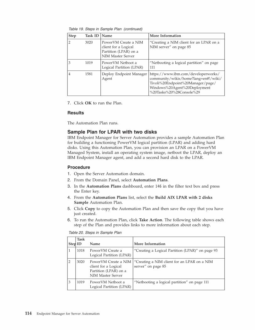
Table 19. Steps in Sample Plan (continued)
Step Task ID Name More Information
2 3020 PowerVM Create a NIMclient for a LogicalPartition (LPAR) on aNIM Master Server
“Creating a NIM client for an LPAR on aNIM server” on page 85
3 1019 PowerVM Netboot aLogical Partition (LPAR)
“Netbooting a logical partition” on page111
4 1581 Deploy Endpoint ManagerAgent
https://www.ibm.com/developerworks/community/wikis/home?lang=en#!/wiki/Tivoli%20Endpoint%20Manager/page/Windows%20Agent%20Deployment%20Tasks%20%28Console%29
7. Click OK to run the Plan.
Results
The Automation Plan runs.
Sample Plan for LPAR with two disksIBM Endpoint Manager for Server Automation provides a sample Automation Planfor building a functioning PowerVM logical partition (LPAR) and adding harddisks. Using this Automation Plan, you can provision an LPAR on a PowerVMManaged System, install an operating system image, netboot the LPAR, deploy anIBM Endpoint Manager agent, and add a second hard disk to the LPAR.
Procedure1. Open the Server Automation domain.2. From the Domain Panel, select Automation Plans.3. In the Automation Plans dashboard, enter 146 in the filter text box and press
the Enter key.4. From the Automation Plans list, select the Build AIX LPAR with 2 disks
Sample Automation Plan.5. Click Copy to copy the Automation Plan and then save the copy that you have
just created.6. To run the Automation Plan, click Take Action. The following table shows each
step of the Plan and provides links to more information about each step.
Table 20. Steps in Sample Plan
StepTaskID Name More Information
1 1018 PowerVM Create aLogical Partition (LPAR)
“Creating a Logical Partition (LPAR)” on page 93
2 3020 PowerVM Create a NIMclient for a LogicalPartition (LPAR) on aNIM Master Server
“Creating a NIM client for an LPAR on a NIMserver” on page 85
3 1019 PowerVM Netboot aLogical Partition (LPAR)
“Netbooting a logical partition” on page 111
114 Endpoint Manager for Server Automation
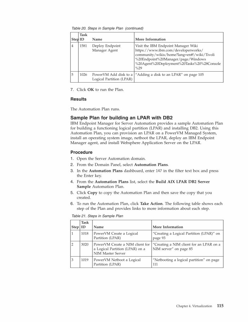
Table 20. Steps in Sample Plan (continued)
StepTaskID Name More Information
4 1581 Deploy EndpointManager Agent
Visit the IBM Endpoint Manager Wikihttps://www.ibm.com/developerworks/community/wikis/home?lang=en#!/wiki/Tivoli%20Endpoint%20Manager/page/Windows%20Agent%20Deployment%20Tasks%20%28Console%29
5 1026 PowerVM Add disk to aLogical Partition (LPAR)
“Adding a disk to an LPAR” on page 105
7. Click OK to run the Plan.
Results
The Automation Plan runs.
Sample Plan for building an LPAR with DB2IBM Endpoint Manager for Server Automation provides a sample Automation Planfor building a functioning logical partition (LPAR) and installing DB2. Using thisAutomation Plan, you can provision an LPAR on a PowerVM Managed System,install an operating system image, netboot the LPAR, deploy an IBM EndpointManager agent, and install Websphere Application Server on the LPAR.
Procedure1. Open the Server Automation domain.2. From the Domain Panel, select Automation Plans.3. In the Automation Plans dashboard, enter 147 in the filter text box and press
the Enter key.4. From the Automation Plans list, select the Build AIX LPAR DB2 Server
Sample Automation Plan.5. Click Copy to copy the Automation Plan and then save the copy that you
created.6. To run the Automation Plan, click Take Action. The following table shows each
step of the Plan and provides links to more information about each step.
Table 21. Steps in Sample Plan
StepTaskID Name More Information
1 1018 PowerVM Create a LogicalPartition (LPAR)
“Creating a Logical Partition (LPAR)” onpage 93
2 3020 PowerVM Create a NIM client fora Logical Partition (LPAR) on aNIM Master Server
“Creating a NIM client for an LPAR on aNIM server” on page 85
3 1019 PowerVM Netboot a LogicalPartition (LPAR)
“Netbooting a logical partition” on page111
Chapter 4. Virtualization 115
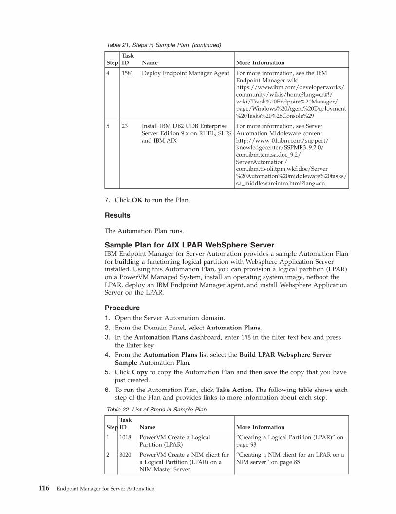
Table 21. Steps in Sample Plan (continued)
StepTaskID Name More Information
4 1581 Deploy Endpoint Manager Agent For more information, see the IBMEndpoint Manager wikihttps://www.ibm.com/developerworks/community/wikis/home?lang=en#!/wiki/Tivoli%20Endpoint%20Manager/page/Windows%20Agent%20Deployment%20Tasks%20%28Console%29
5 23 Install IBM DB2 UDB EnterpriseServer Edition 9.x on RHEL, SLESand IBM AIX
For more information, see ServerAutomation Middleware contenthttp://www-01.ibm.com/support/knowledgecenter/SSPMR3_9.2.0/com.ibm.tem.sa.doc_9.2/ServerAutomation/com.ibm.tivoli.tpm.wkf.doc/Server%20Automation%20middleware%20tasks/sa_middlewareintro.html?lang=en
7. Click OK to run the Plan.
Results
The Automation Plan runs.
Sample Plan for AIX LPAR WebSphere ServerIBM Endpoint Manager for Server Automation provides a sample Automation Planfor building a functioning logical partition with Websphere Application Serverinstalled. Using this Automation Plan, you can provision a logical partition (LPAR)on a PowerVM Managed System, install an operating system image, netboot theLPAR, deploy an IBM Endpoint Manager agent, and install Websphere ApplicationServer on the LPAR.
Procedure1. Open the Server Automation domain.2. From the Domain Panel, select Automation Plans.3. In the Automation Plans dashboard, enter 148 in the filter text box and press
the Enter key.4. From the Automation Plans list select the Build LPAR Websphere Server
Sample Automation Plan.5. Click Copy to copy the Automation Plan and then save the copy that you have
just created.6. To run the Automation Plan, click Take Action. The following table shows each
step of the Plan and provides links to more information about each step.
Table 22. List of Steps in Sample Plan
StepTaskID Name More Information
1 1018 PowerVM Create a LogicalPartition (LPAR)
“Creating a Logical Partition (LPAR)” onpage 93
2 3020 PowerVM Create a NIM client fora Logical Partition (LPAR) on aNIM Master Server
“Creating a NIM client for an LPAR on aNIM server” on page 85
116 Endpoint Manager for Server Automation
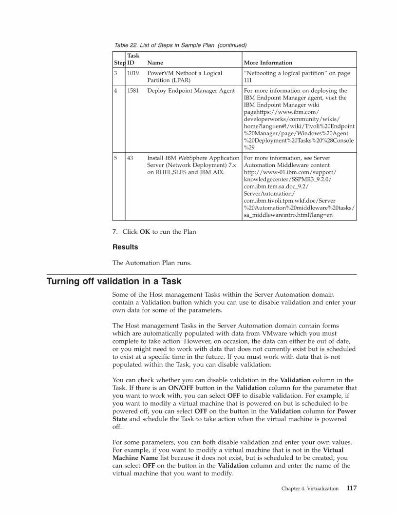
Table 22. List of Steps in Sample Plan (continued)
StepTaskID Name More Information
3 1019 PowerVM Netboot a LogicalPartition (LPAR)
“Netbooting a logical partition” on page111
4 1581 Deploy Endpoint Manager Agent For more information on deploying theIBM Endpoint Manager agent, visit theIBM Endpoint Manager wikipagehttps://www.ibm.com/developerworks/community/wikis/home?lang=en#!/wiki/Tivoli%20Endpoint%20Manager/page/Windows%20Agent%20Deployment%20Tasks%20%28Console%29
5 43 Install IBM WebSphere ApplicationServer (Network Deployment) 7.xon RHEL,SLES and IBM AIX.
For more information, see ServerAutomation Middleware contenthttp://www-01.ibm.com/support/knowledgecenter/SSPMR3_9.2.0/com.ibm.tem.sa.doc_9.2/ServerAutomation/com.ibm.tivoli.tpm.wkf.doc/Server%20Automation%20middleware%20tasks/sa_middlewareintro.html?lang=en
7. Click OK to run the Plan
Results
The Automation Plan runs.
Turning off validation in a TaskSome of the Host management Tasks within the Server Automation domaincontain a Validation button which you can use to disable validation and enter yourown data for some of the parameters.
The Host management Tasks in the Server Automation domain contain formswhich are automatically populated with data from VMware which you mustcomplete to take action. However, on occasion, the data can either be out of date,or you might need to work with data that does not currently exist but is scheduledto exist at a specific time in the future. If you must work with data that is notpopulated within the Task, you can disable validation.
You can check whether you can disable validation in the Validation column in theTask. If there is an ON/OFF button in the Validation column for the parameter thatyou want to work with, you can select OFF to disable validation. For example, ifyou want to modify a virtual machine that is powered on but is scheduled to bepowered off, you can select OFF on the button in the Validation column for PowerState and schedule the Task to take action when the virtual machine is poweredoff.
For some parameters, you can both disable validation and enter your own values.For example, if you want to modify a virtual machine that is not in the VirtualMachine Name list because it does not exist, but is scheduled to be created, youcan select OFF on the button in the Validation column and enter the name of thevirtual machine that you want to modify.
Chapter 4. Virtualization 117

Disable validation only if you can ensure that your data is correct. When youdisable validation on a parameter and take action, the IBM Endpoint Managerconsole does not verify whether the parameter contains valid data. If invalid datais used, the Task fails in VMware.
If you disable validation for a parameter, other parameters which are dependenton that parameter might be affected. For example, in the VMware Modify VirtualMachine Task, if you disable the Virtual Machine Name parameter, the PowerState and the Disk size parameters are also disabled. The validation on theseparameters is disabled because the IBM Endpoint Manager console cannot validatethe power state or the disk size of a virtual machine that is not listed.
118 Endpoint Manager for Server Automation
Chapter 5. Configuring your system and best practices
This section describes how the IBM Endpoint Manager architecture is relevant forServer Automation. It also describes how Server Automation can affect IBMEndpoint Manager performance.
When configured correctly, Server Automation does not adversely affect IBMEndpoint Manager performance. However, be aware of the potential impact thatServer Automation action sequencing can have on system performance. You alsoneed to know how the IBM Endpoint Manager architecture affects ServerAutomation functionality. For example, because of the refresh interval betweenWeb Reports and the server, there is a delay of 15 seconds between when youcreate a Automation Plan and when that Automation Plan is available in theAutomation Plan Engine.
The configuration information described here assumes that you have existingknowledge of the IBM Endpoint Manager platform and performance tuning. If youare not familiar with IBM Endpoint Manager performance and tuning, first readthe IBM Endpoint Manager documentation on performance, deployments, andtroubleshooting.
OverviewIBM Endpoint Manager for Server Automation is built on the IBM EndpointManager platform. Server Automation uses the key IBM Endpoint Managerstrengths and advantages. It is also subject to the IBM Endpoint Managerarchitecture capacity considerations and latency. Read the configurationdocumentation included here to understand how IBM Endpoint Managerarchitecture is relevant to IBM Endpoint Manager for Server Automation and howyou can configure your system for optimum performance. This documentation alsodescribes how Server Automation functionality influences IBM Endpoint Managersystem performance.
Server Automation provides the capability to sequence Fixlets, Tasks, and Baselinesacross multiple endpoints. You sequence Fixlets, Tasks, and Baselines acrossendpoints by creating and running an Automation Plan. Automation Plans areprocessed by the Automation Plan Engine. When you run an Automation Plan,new actions are created on the IBM Endpoint Manager system. An action is createdfor the Automation Plan and the Automation Plan Engine creates an action foreach step in the Automation Plan. When the step has completed the AutomationPlan Engine stops the action. In addition, if you schedule an Automation Plan anduse the Prefetch downloads feature to download content in advance of theAutomation Plan execution, an additional action is created for each step in theAutomation Plan that contains a prefetch or download statement. You might needto monitor the number of open actions to ensure that system performance is notadversely affected. In a traditional IBM Endpoint Manager environment, openactions are created manually by the console operator. Because the Automation PlanEngine automatically creates open actions, you need to be aware of the potentialimpact on system performance if there are too many open actions on the system.Similarly, depending on the number of Automation Plans that you create, theAutomation Plan Engine can potentially leave a large number of stopped andexpired actions. Therefore, you might need to monitor the number of open, closed,and expired actions on the system and take action.
© International Business Machines Corporation 2012 119
There are some latency and refresh considerations that influence ServerAutomation behaviour and you need to understand these factors to use ServerAutomation effectively. For example, when you create an Automation Plan, theAutomation Plan is not immediately available in the Automation Plan Engine.Normally, there is a 15-seconds delay because of the refresh interval between WebReports and the IBM Endpoint Manager server.
This documentation assumes that you are familiar with the IBM Endpoint Managerplatform and architecture and that you are experienced in using IBM EndpointManager. If you are not familiar with IBM Endpoint Manager, read the followingIBM Endpoint Manager documentation before you read this documentation onServer Automation:v Tivoli Endpoint Manager Administrator's Guide - Overviewv Tivoli Endpoint Manager Administrator's Guide - Configuring the Componentsv The Network Traffic Guidev Performance Configurations Guide
Server Automation componentsIBM Endpoint Manager for Server Automation uses IBM Endpoint Managertechnology and is subject to the same latency considerations as IBM EndpointManager. Read the information in this section to learn about the inherent latencyand how it affects Server Automation.
Review the following information to understand how latency can affect yourServer Automation plans:v When you create a plan, there is approximately 15 seconds delay from the time
you create the plan to the time it is available in the Automation Plan Engine.This delay is caused by the refresh interval between Web Reports and the server,the recommended default and the minimum delay is 15 seconds.
v There is a delay between the time a result from an endpoint is stored in the IBMEndpoint Manager database to when it is available to the Automation PlanEngine. This can be up to 15 seconds (assuming the Web Reports refresh intervalis 15 seconds). A similar delay occurs for results being displayed in the console.
v There is a three-seconds delay for each relay to communicate with the IBMEndpoint Manager server. This value cannot be tuned or improved. Relaystransmit their responses every three seconds. The more relays that you have onyour system, the longer it takes for results to be returned from the endpoints tothe server and the Automation Plan Engine.
v IBM Endpoint Manager uses the http protocol for communication between theserver and the relays.
v IBM Endpoint Manager uses the UDP protocol for communication between therelays and IBM Endpoint Manager client. Though not a strict requirement, if youdo not use the UDP protocol, the alternative is http polling by the agent, whichis infrequent.
The following diagram displays the main components in the IBM EndpointManager architecture. Server Automation uses the same communication protocolsand components.
120 Endpoint Manager for Server Automation
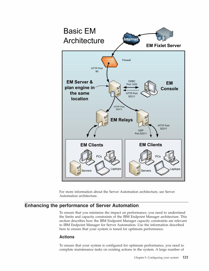
Basic EM Architecture
EM Fixlet Server
Firewall
HTTP Port 80
EM Server &plan engine in
the samelocation
ODBC Port 1433
HTTP Port 52311
EMConsole
EM Relays
HTTP Port 52311
UDPPort 52311
HTTP Port 52311
EM Clients EM Clients
PCs PCs
Servers ServersLaptops Laptops
Internet
For more information about the Server Automation architecture, see ServerAutomation architecture.
Enhancing the performance of Server AutomationTo ensure that you minimize the impact on performance, you need to understandthe limits and capacity constraints of the IBM Endpoint Manager architecture. Thissection describes how the IBM Endpoint Manager capacity constraints are relevantto IBM Endpoint Manager for Server Automation. Use the information describedhere to ensure that your system is tuned for optimum performance.
Actions
To ensure that your system is configured for optimum performance, you need tocomplete maintenance tasks on existing actions in the system. A large number of
Chapter 5. Configuring your system 121
actions on the system affects system performance. The number of open actions onthe system affects system resources. Closed actions also use system resources, asthe system reports on all closed actions.
Try to ensure that the maximum number of open actions on the system does notexceed 2,500. As the number of open actions on the system exceeds 2,500, systemperformance is adversely affected. It is important to note that the Automation PlanEngine automatically generates actions as it processes the Automation Plans thatyou create. Therefore, you might need to check the number of open actions on thesystem more regularly than if you were creating actions manually.
Important: There is a potential performance impact associated with using thePrefetch downloads option because an additional action is created for each stepthat requires software downloads. The recommended maximum number of openactions on the system is 2,500. For any given Automation Plan, an action is openfor the Automation Plan and also for each individual step in the Automation Plan.If you use the Prefetch downloads option, additional actions are created andopened for each step that requires software downloads. So instead of having twoopen actions per Automation Plan at any one point (one action for the AutomationPlan and one for the current step) there are additional actions opened for each stepthat requires software downloads.
To check the number of open actions on the system, complete the following:1. From the IBM Endpoint Manager console, click the BigFix Management
domain.2. Click Deployment Health Checks.3. Navigate to the Deployment Optimization section.4. Expand the Open Actions node. The system provides information about the
number of actions currently open. Review the results and identify if you needto take action.
Try to ensure that the number of closed actions on the system does not exceed10,000. To check the number of closed actions on the system, complete thefollowing:1. From the IBM Endpoint Manager console, click the BigFix Management
domain.2. Click Deployment Health Checks.3. Navigate to the BES Console Health section.4. Expand the Stopped And Expired Actions section. Review the results and
decide if you need to take action.
To reduce the number of closed actions, you can delete the actions from the server.However, when you delete actions from the server, they remain on the database.To completely remove closed actions, you can purge the actions from the system.
When you are designing your Automation Plan, make sure that you design youraction applicability so that you are targeting only relevant endpoints. Ensure thatthe Site to which you publish your actions is suitable for the endpoints you wantto target for Server Automation. For example, many of the endpoints on yournetwork might not be relevant targets for your Automation Plan. Therefore, it isadvisable to publish your actions to a more specific group of computers, such asservers.
122 Endpoint Manager for Server Automation

Each Automation Plan is a Fixlet. To ensure that your Automation Plans are notevaluated by non-relevant endpoints, store your Automation Plans in a site that isnot subscribed to by IBM Endpoint Manager endpoints.
Chapter 5. Configuring your system 123

124 Endpoint Manager for Server Automation
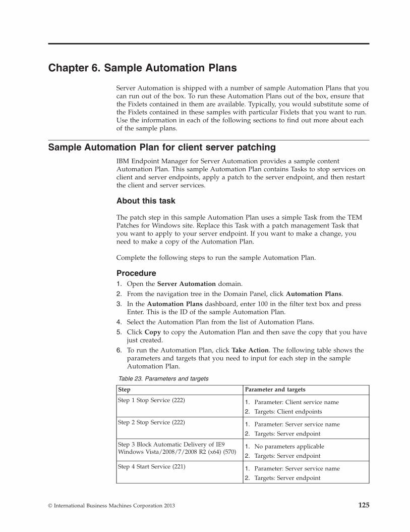
Chapter 6. Sample Automation Plans
Server Automation is shipped with a number of sample Automation Plans that youcan run out of the box. To run these Automation Plans out of the box, ensure thatthe Fixlets contained in them are available. Typically, you would substitute some ofthe Fixlets contained in these samples with particular Fixlets that you want to run.Use the information in each of the following sections to find out more about eachof the sample plans.
Sample Automation Plan for client server patchingIBM Endpoint Manager for Server Automation provides a sample contentAutomation Plan. This sample Automation Plan contains Tasks to stop services onclient and server endpoints, apply a patch to the server endpoint, and then restartthe client and server services.
About this task
The patch step in this sample Automation Plan uses a simple Task from the TEMPatches for Windows site. Replace this Task with a patch management Task thatyou want to apply to your server endpoint. If you want to make a change, youneed to make a copy of the Automation Plan.
Complete the following steps to run the sample Automation Plan.
Procedure1. Open the Server Automation domain.2. From the navigation tree in the Domain Panel, click Automation Plans.3. In the Automation Plans dashboard, enter 100 in the filter text box and press
Enter. This is the ID of the sample Automation Plan.4. Select the Automation Plan from the list of Automation Plans.5. Click Copy to copy the Automation Plan and then save the copy that you have
just created.6. To run the Automation Plan, click Take Action. The following table shows the
parameters and targets that you need to input for each step in the sampleAutomation Plan.
Table 23. Parameters and targets
Step Parameter and targets
Step 1 Stop Service (222) 1. Parameter: Client service name
2. Targets: Client endpoints
Step 2 Stop Service (222) 1. Parameter: Server service name
2. Targets: Server endpoint
Step 3 Block Automatic Delivery of IE9Windows Vista/2008/7/2008 R2 (x64) (570)
1. No parameters applicable
2. Targets: Server endpoint
Step 4 Start Service (221) 1. Parameter: Server service name
2. Targets: Server endpoint
© International Business Machines Corporation 2013 125
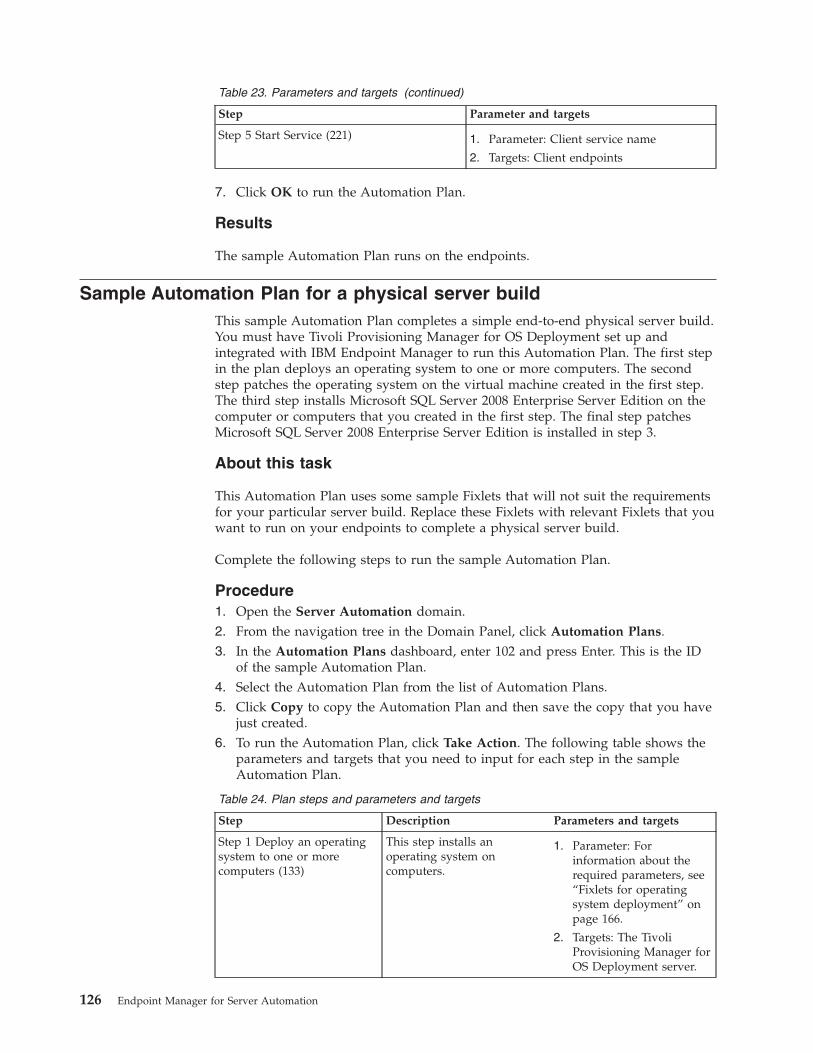
Table 23. Parameters and targets (continued)
Step Parameter and targets
Step 5 Start Service (221) 1. Parameter: Client service name
2. Targets: Client endpoints
7. Click OK to run the Automation Plan.
Results
The sample Automation Plan runs on the endpoints.
Sample Automation Plan for a physical server buildThis sample Automation Plan completes a simple end-to-end physical server build.You must have Tivoli Provisioning Manager for OS Deployment set up andintegrated with IBM Endpoint Manager to run this Automation Plan. The first stepin the plan deploys an operating system to one or more computers. The secondstep patches the operating system on the virtual machine created in the first step.The third step installs Microsoft SQL Server 2008 Enterprise Server Edition on thecomputer or computers that you created in the first step. The final step patchesMicrosoft SQL Server 2008 Enterprise Server Edition is installed in step 3.
About this task
This Automation Plan uses some sample Fixlets that will not suit the requirementsfor your particular server build. Replace these Fixlets with relevant Fixlets that youwant to run on your endpoints to complete a physical server build.
Complete the following steps to run the sample Automation Plan.
Procedure1. Open the Server Automation domain.2. From the navigation tree in the Domain Panel, click Automation Plans.3. In the Automation Plans dashboard, enter 102 and press Enter. This is the ID
of the sample Automation Plan.4. Select the Automation Plan from the list of Automation Plans.5. Click Copy to copy the Automation Plan and then save the copy that you have
just created.6. To run the Automation Plan, click Take Action. The following table shows the
parameters and targets that you need to input for each step in the sampleAutomation Plan.
Table 24. Plan steps and parameters and targets
Step Description Parameters and targets
Step 1 Deploy an operatingsystem to one or morecomputers (133)
This step installs anoperating system oncomputers.
1. Parameter: Forinformation about therequired parameters, see“Fixlets for operatingsystem deployment” onpage 166.
2. Targets: The TivoliProvisioning Manager forOS Deployment server.
126 Endpoint Manager for Server Automation
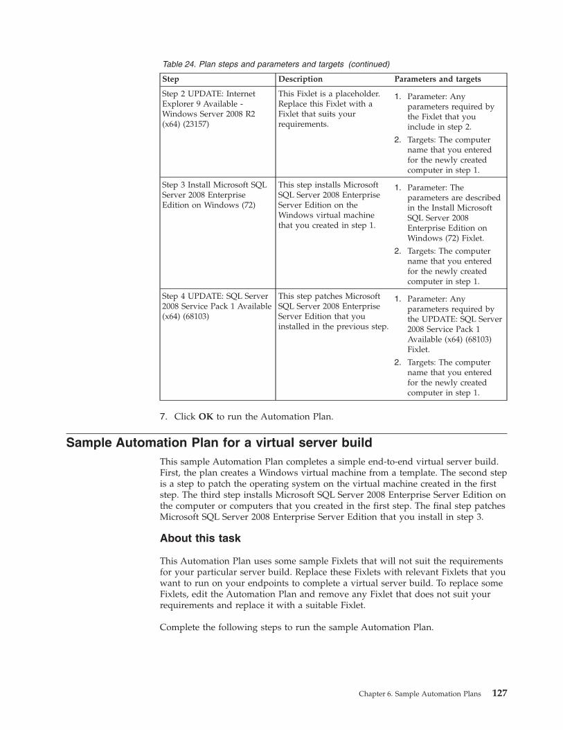
Table 24. Plan steps and parameters and targets (continued)
Step Description Parameters and targets
Step 2 UPDATE: InternetExplorer 9 Available -Windows Server 2008 R2(x64) (23157)
This Fixlet is a placeholder.Replace this Fixlet with aFixlet that suits yourrequirements.
1. Parameter: Anyparameters required bythe Fixlet that youinclude in step 2.
2. Targets: The computername that you enteredfor the newly createdcomputer in step 1.
Step 3 Install Microsoft SQLServer 2008 EnterpriseEdition on Windows (72)
This step installs MicrosoftSQL Server 2008 EnterpriseServer Edition on theWindows virtual machinethat you created in step 1.
1. Parameter: Theparameters are describedin the Install MicrosoftSQL Server 2008Enterprise Edition onWindows (72) Fixlet.
2. Targets: The computername that you enteredfor the newly createdcomputer in step 1.
Step 4 UPDATE: SQL Server2008 Service Pack 1 Available(x64) (68103)
This step patches MicrosoftSQL Server 2008 EnterpriseServer Edition that youinstalled in the previous step.
1. Parameter: Anyparameters required bythe UPDATE: SQL Server2008 Service Pack 1Available (x64) (68103)Fixlet.
2. Targets: The computername that you enteredfor the newly createdcomputer in step 1.
7. Click OK to run the Automation Plan.
Sample Automation Plan for a virtual server buildThis sample Automation Plan completes a simple end-to-end virtual server build.First, the plan creates a Windows virtual machine from a template. The second stepis a step to patch the operating system on the virtual machine created in the firststep. The third step installs Microsoft SQL Server 2008 Enterprise Server Edition onthe computer or computers that you created in the first step. The final step patchesMicrosoft SQL Server 2008 Enterprise Server Edition that you install in step 3.
About this task
This Automation Plan uses some sample Fixlets that will not suit the requirementsfor your particular server build. Replace these Fixlets with relevant Fixlets that youwant to run on your endpoints to complete a virtual server build. To replace someFixlets, edit the Automation Plan and remove any Fixlet that does not suit yourrequirements and replace it with a suitable Fixlet.
Complete the following steps to run the sample Automation Plan.
Chapter 6. Sample Automation Plans 127
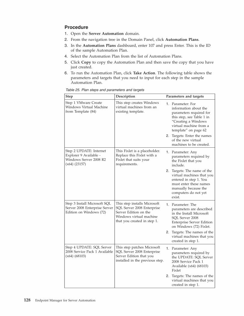
Procedure1. Open the Server Automation domain.2. From the navigation tree in the Domain Panel, click Automation Plans.3. In the Automation Plans dashboard, enter 107 and press Enter. This is the ID
of the sample Automation Plan.4. Select the Automation Plan from the list of Automation Plans.5. Click Copy to copy the Automation Plan and then save the copy that you have
just created.6. To run the Automation Plan, click Take Action. The following table shows the
parameters and targets that you need to input for each step in the sampleAutomation Plan.
Table 25. Plan steps and parameters and targets
Step Description Parameters and targets
Step 1 VMware CreateWindows Virtual Machinefrom Template (84)
This step creates Windowsvirtual machines from anexisting template.
1. Parameter: Forinformation about theparameters required forthis step, see Table 1 in“Creating a Windowsvirtual machine from atemplate” on page 62
2. Targets: Enter the namesof the new virtualmachines to be created.
Step 2 UPDATE: InternetExplorer 9 Available -Windows Server 2008 R2(x64) (23157)
This Fixlet is a placeholder.Replace this Fixlet with aFixlet that suits yourrequirements.
1. Parameter: Anyparameters required bythe Fixlet that youinclude.
2. Targets: The name of thevirtual machines that youentered in step 1. Youmust enter these namesmanually because thecomputers do not yetexist.
Step 3 Install Microsoft SQLServer 2008 Enterprise ServerEdition on Windows (72)
This step installs MicrosoftSQL Server 2008 EnterpriseServer Edition on theWindows virtual machinethat you created in step 1.
1. Parameter: Theparameters are describedin the Install MicrosoftSQL Server 2008Enterprise Server Editionon Windows (72) Fixlet.
2. Targets: The names of thevirtual machines that youcreated in step 1.
Step 4 UPDATE: SQL Server2008 Service Pack 1 Available(x64) (68103)
This step patches MicrosoftSQL Server 2008 EnterpriseServer Edition that youinstalled in the previous step.
1. Parameter: Anyparameters required bythe UPDATE: SQL Server2008 Service Pack 1Available (x64) (68103)Fixlet
2. Targets: The names of thevirtual machines that youcreated in step 1.
128 Endpoint Manager for Server Automation
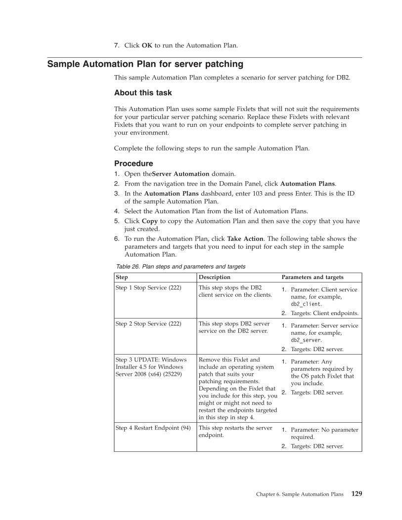
7. Click OK to run the Automation Plan.
Sample Automation Plan for server patchingThis sample Automation Plan completes a scenario for server patching for DB2.
About this task
This Automation Plan uses some sample Fixlets that will not suit the requirementsfor your particular server patching scenario. Replace these Fixlets with relevantFixlets that you want to run on your endpoints to complete server patching inyour environment.
Complete the following steps to run the sample Automation Plan.
Procedure1. Open theServer Automation domain.2. From the navigation tree in the Domain Panel, click Automation Plans.3. In the Automation Plans dashboard, enter 103 and press Enter. This is the ID
of the sample Automation Plan.4. Select the Automation Plan from the list of Automation Plans.5. Click Copy to copy the Automation Plan and then save the copy that you have
just created.6. To run the Automation Plan, click Take Action. The following table shows the
parameters and targets that you need to input for each step in the sampleAutomation Plan.
Table 26. Plan steps and parameters and targets
Step Description Parameters and targets
Step 1 Stop Service (222) This step stops the DB2client service on the clients.
1. Parameter: Client servicename, for example,db2_client.
2. Targets: Client endpoints.
Step 2 Stop Service (222) This step stops DB2 serverservice on the DB2 server.
1. Parameter: Server servicename, for example,db2_server.
2. Targets: DB2 server.
Step 3 UPDATE: WindowsInstaller 4.5 for WindowsServer 2008 (x64) (25229)
Remove this Fixlet andinclude an operating systempatch that suits yourpatching requirements.Depending on the Fixlet thatyou include for this step, youmight or might not need torestart the endpoints targetedin this step in step 4.
1. Parameter: Anyparameters required bythe OS patch Fixlet thatyou include.
2. Targets: DB2 server.
Step 4 Restart Endpoint (94) This step restarts the serverendpoint.
1. Parameter: No parameterrequired.
2. Targets: DB2 server.
Chapter 6. Sample Automation Plans 129
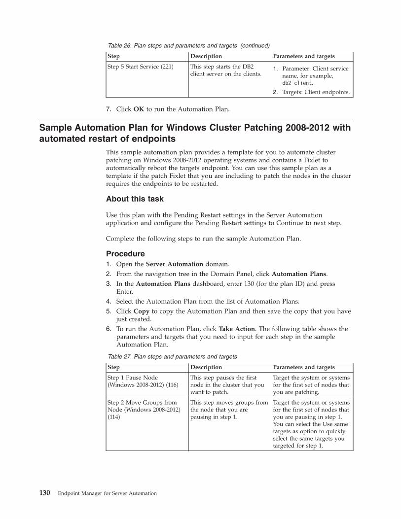
Table 26. Plan steps and parameters and targets (continued)
Step Description Parameters and targets
Step 5 Start Service (221) This step starts the DB2client server on the clients.
1. Parameter: Client servicename, for example,db2_client.
2. Targets: Client endpoints.
7. Click OK to run the Automation Plan.
Sample Automation Plan for Windows Cluster Patching 2008-2012 withautomated restart of endpoints
This sample automation plan provides a template for you to automate clusterpatching on Windows 2008-2012 operating systems and contains a Fixlet toautomatically reboot the targets endpoint. You can use this sample plan as atemplate if the patch Fixlet that you are including to patch the nodes in the clusterrequires the endpoints to be restarted.
About this task
Use this plan with the Pending Restart settings in the Server Automationapplication and configure the Pending Restart settings to Continue to next step.
Complete the following steps to run the sample Automation Plan.
Procedure1. Open the Server Automation domain.2. From the navigation tree in the Domain Panel, click Automation Plans.3. In the Automation Plans dashboard, enter 130 (for the plan ID) and press
Enter.4. Select the Automation Plan from the list of Automation Plans.5. Click Copy to copy the Automation Plan and then save the copy that you have
just created.6. To run the Automation Plan, click Take Action. The following table shows the
parameters and targets that you need to input for each step in the sampleAutomation Plan.
Table 27. Plan steps and parameters and targets
Step Description Parameters and targets
Step 1 Pause Node(Windows 2008-2012) (116)
This step pauses the firstnode in the cluster that youwant to patch.
Target the system or systemsfor the first set of nodes thatyou are patching.
Step 2 Move Groups fromNode (Windows 2008-2012)(114)
This step moves groups fromthe node that you arepausing in step 1.
Target the system or systemsfor the first set of nodes thatyou are pausing in step 1.You can select the Use sametargets as option to quicklyselect the same targets youtargeted for step 1.
130 Endpoint Manager for Server Automation
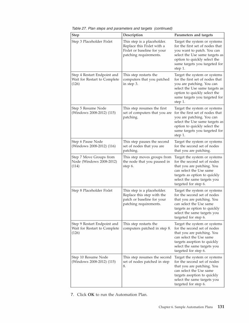
Table 27. Plan steps and parameters and targets (continued)
Step Description Parameters and targets
Step 3 Placeholder Fixlet This step is a placeholder.Replace this Fixlet with aFixlet or baseline for yourpatching requirements.
Target the system or systemsfor the first set of nodes thatyou want to patch. You canselect the Use same targets asoption to quickly select thesame targets you targeted forstep 1.
Step 4 Restart Endpoint andWait for Restart to Complete(126)
This step restarts thecomputers that you patchedin step 3.
Target the system or systemsfor the first set of nodes thatyou are patching. You canselect the Use same targets asoption to quickly select thesame targets you targeted forstep 1.
Step 5 Resume Node(Windows 2008-2012) (115)
This step resumes the firstset of computers that you arepatching.
Target the system or systemsfor the first set of nodes thatyou are patching. You canselect the Use same targets asoption to quickly select thesame targets you targeted forstep 1.
Step 6 Pause Node(Windows 2008-2012) (116)
This step pauses the secondset of nodes that you arepatching.
Target the system or systemsfor the second set of nodesthat you are patching.
Step 7 Move Groups fromNode (Windows 2008-2012)(114)
This step moves groups fromthe node that you paused instep 6.
Target the system or systemsfor the second set of nodesthat you are patching. Youcan select the Use sametargets as option to quicklyselect the same targets youtargeted for step 6.
Step 8 Placeholder Fixlet This step is a placeholder.Replace this step with thepatch or baseline for yourpatching requirements.
Target the system or systemsfor the second set of nodesthat you are patching. Youcan select the Use sametargets as option to quicklyselect the same targets youtargeted for step 6.
Step 9 Restart Endpoint andWait for Restart to Complete(126)
This step restarts thecomputers patched in step 8.
Target the system or systemsfor the second set of nodesthat you are patching. Youcan select the Use sametargets asoption to quicklyselect the same targets youtargeted for step 6.
Step 10 Resume Node(Windows 2008-2012) (115)
This step resumes the secondset of nodes patched in step8.
Target the system or systemsfor the second set of nodesthat you are patching. Youcan select the Use sametargets asoption to quicklyselect the same targets youtargeted for step 6.
7. Click OK to run the Automation Plan.
Chapter 6. Sample Automation Plans 131
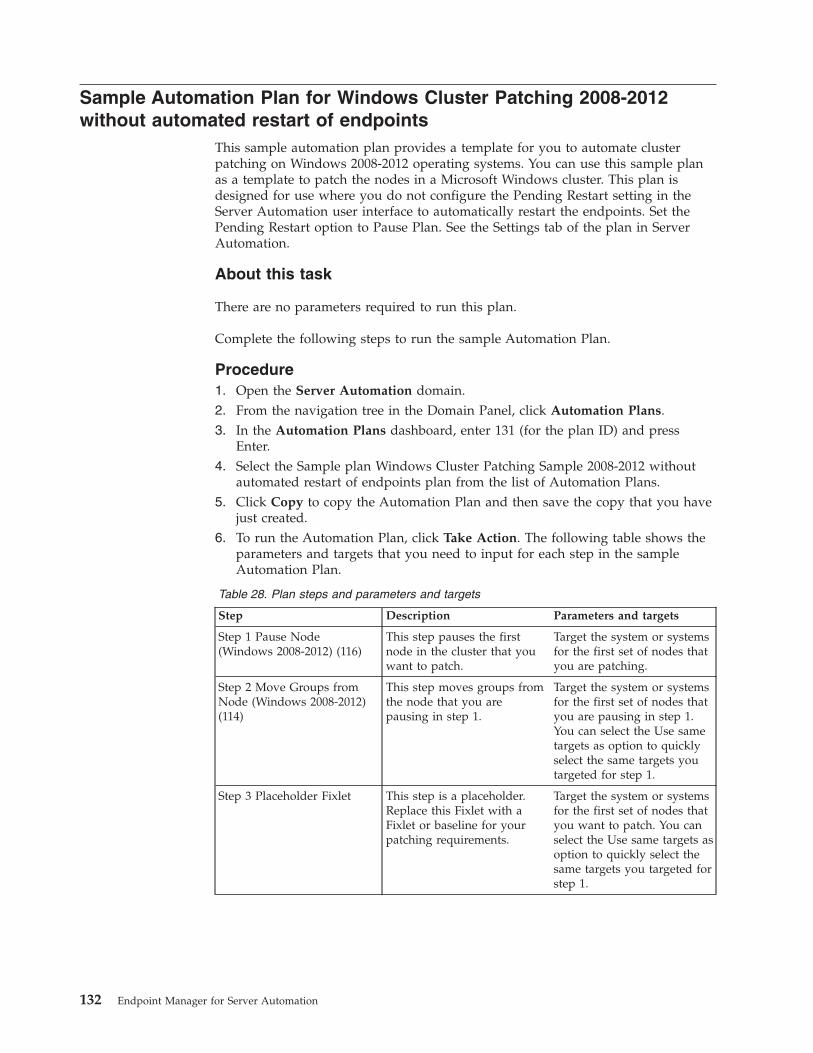
Sample Automation Plan for Windows Cluster Patching 2008-2012without automated restart of endpoints
This sample automation plan provides a template for you to automate clusterpatching on Windows 2008-2012 operating systems. You can use this sample planas a template to patch the nodes in a Microsoft Windows cluster. This plan isdesigned for use where you do not configure the Pending Restart setting in theServer Automation user interface to automatically restart the endpoints. Set thePending Restart option to Pause Plan. See the Settings tab of the plan in ServerAutomation.
About this task
There are no parameters required to run this plan.
Complete the following steps to run the sample Automation Plan.
Procedure1. Open the Server Automation domain.2. From the navigation tree in the Domain Panel, click Automation Plans.3. In the Automation Plans dashboard, enter 131 (for the plan ID) and press
Enter.4. Select the Sample plan Windows Cluster Patching Sample 2008-2012 without
automated restart of endpoints plan from the list of Automation Plans.5. Click Copy to copy the Automation Plan and then save the copy that you have
just created.6. To run the Automation Plan, click Take Action. The following table shows the
parameters and targets that you need to input for each step in the sampleAutomation Plan.
Table 28. Plan steps and parameters and targets
Step Description Parameters and targets
Step 1 Pause Node(Windows 2008-2012) (116)
This step pauses the firstnode in the cluster that youwant to patch.
Target the system or systemsfor the first set of nodes thatyou are patching.
Step 2 Move Groups fromNode (Windows 2008-2012)(114)
This step moves groups fromthe node that you arepausing in step 1.
Target the system or systemsfor the first set of nodes thatyou are pausing in step 1.You can select the Use sametargets as option to quicklyselect the same targets youtargeted for step 1.
Step 3 Placeholder Fixlet This step is a placeholder.Replace this Fixlet with aFixlet or baseline for yourpatching requirements.
Target the system or systemsfor the first set of nodes thatyou want to patch. You canselect the Use same targets asoption to quickly select thesame targets you targeted forstep 1.
132 Endpoint Manager for Server Automation
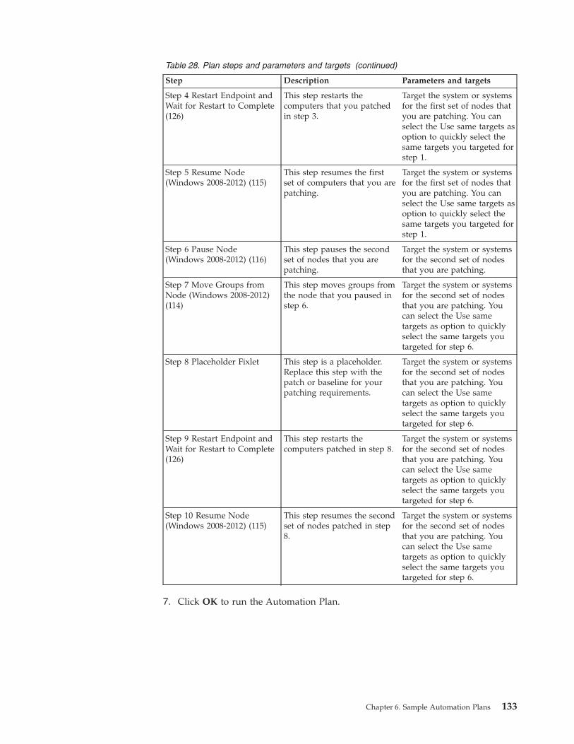
Table 28. Plan steps and parameters and targets (continued)
Step Description Parameters and targets
Step 4 Restart Endpoint andWait for Restart to Complete(126)
This step restarts thecomputers that you patchedin step 3.
Target the system or systemsfor the first set of nodes thatyou are patching. You canselect the Use same targets asoption to quickly select thesame targets you targeted forstep 1.
Step 5 Resume Node(Windows 2008-2012) (115)
This step resumes the firstset of computers that you arepatching.
Target the system or systemsfor the first set of nodes thatyou are patching. You canselect the Use same targets asoption to quickly select thesame targets you targeted forstep 1.
Step 6 Pause Node(Windows 2008-2012) (116)
This step pauses the secondset of nodes that you arepatching.
Target the system or systemsfor the second set of nodesthat you are patching.
Step 7 Move Groups fromNode (Windows 2008-2012)(114)
This step moves groups fromthe node that you paused instep 6.
Target the system or systemsfor the second set of nodesthat you are patching. Youcan select the Use sametargets as option to quicklyselect the same targets youtargeted for step 6.
Step 8 Placeholder Fixlet This step is a placeholder.Replace this step with thepatch or baseline for yourpatching requirements.
Target the system or systemsfor the second set of nodesthat you are patching. Youcan select the Use sametargets as option to quicklyselect the same targets youtargeted for step 6.
Step 9 Restart Endpoint andWait for Restart to Complete(126)
This step restarts thecomputers patched in step 8.
Target the system or systemsfor the second set of nodesthat you are patching. Youcan select the Use sametargets as option to quicklyselect the same targets youtargeted for step 6.
Step 10 Resume Node(Windows 2008-2012) (115)
This step resumes the secondset of nodes patched in step8.
Target the system or systemsfor the second set of nodesthat you are patching. Youcan select the Use sametargets as option to quicklyselect the same targets youtargeted for step 6.
7. Click OK to run the Automation Plan.
Chapter 6. Sample Automation Plans 133
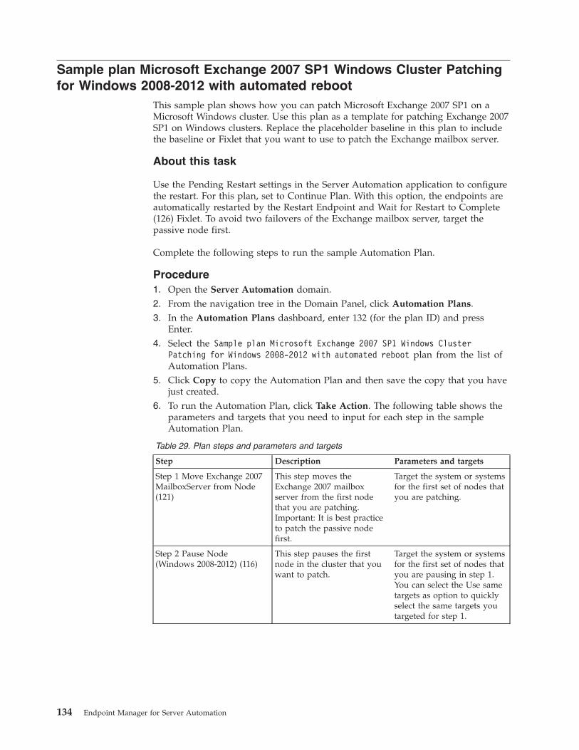
Sample plan Microsoft Exchange 2007 SP1 Windows Cluster Patchingfor Windows 2008-2012 with automated reboot
This sample plan shows how you can patch Microsoft Exchange 2007 SP1 on aMicrosoft Windows cluster. Use this plan as a template for patching Exchange 2007SP1 on Windows clusters. Replace the placeholder baseline in this plan to includethe baseline or Fixlet that you want to use to patch the Exchange mailbox server.
About this task
Use the Pending Restart settings in the Server Automation application to configurethe restart. For this plan, set to Continue Plan. With this option, the endpoints areautomatically restarted by the Restart Endpoint and Wait for Restart to Complete(126) Fixlet. To avoid two failovers of the Exchange mailbox server, target thepassive node first.
Complete the following steps to run the sample Automation Plan.
Procedure1. Open the Server Automation domain.2. From the navigation tree in the Domain Panel, click Automation Plans.3. In the Automation Plans dashboard, enter 132 (for the plan ID) and press
Enter.4. Select the Sample plan Microsoft Exchange 2007 SP1 Windows Cluster
Patching for Windows 2008-2012 with automated reboot plan from the list ofAutomation Plans.
5. Click Copy to copy the Automation Plan and then save the copy that you havejust created.
6. To run the Automation Plan, click Take Action. The following table shows theparameters and targets that you need to input for each step in the sampleAutomation Plan.
Table 29. Plan steps and parameters and targets
Step Description Parameters and targets
Step 1 Move Exchange 2007MailboxServer from Node(121)
This step moves theExchange 2007 mailboxserver from the first nodethat you are patching.Important: It is best practiceto patch the passive nodefirst.
Target the system or systemsfor the first set of nodes thatyou are patching.
Step 2 Pause Node(Windows 2008-2012) (116)
This step pauses the firstnode in the cluster that youwant to patch.
Target the system or systemsfor the first set of nodes thatyou are pausing in step 1.You can select the Use sametargets as option to quicklyselect the same targets youtargeted for step 1.
134 Endpoint Manager for Server Automation
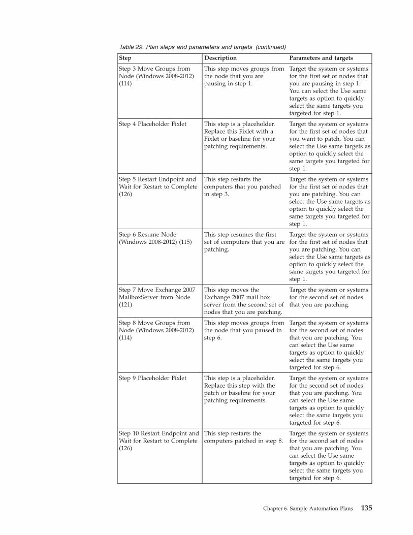
Table 29. Plan steps and parameters and targets (continued)
Step Description Parameters and targets
Step 3 Move Groups fromNode (Windows 2008-2012)(114)
This step moves groups fromthe node that you arepausing in step 1.
Target the system or systemsfor the first set of nodes thatyou are pausing in step 1.You can select the Use sametargets as option to quicklyselect the same targets youtargeted for step 1.
Step 4 Placeholder Fixlet This step is a placeholder.Replace this Fixlet with aFixlet or baseline for yourpatching requirements.
Target the system or systemsfor the first set of nodes thatyou want to patch. You canselect the Use same targets asoption to quickly select thesame targets you targeted forstep 1.
Step 5 Restart Endpoint andWait for Restart to Complete(126)
This step restarts thecomputers that you patchedin step 3.
Target the system or systemsfor the first set of nodes thatyou are patching. You canselect the Use same targets asoption to quickly select thesame targets you targeted forstep 1.
Step 6 Resume Node(Windows 2008-2012) (115)
This step resumes the firstset of computers that you arepatching.
Target the system or systemsfor the first set of nodes thatyou are patching. You canselect the Use same targets asoption to quickly select thesame targets you targeted forstep 1.
Step 7 Move Exchange 2007MailboxServer from Node(121)
This step moves theExchange 2007 mail boxserver from the second set ofnodes that you are patching.
Target the system or systemsfor the second set of nodesthat you are patching.
Step 8 Move Groups fromNode (Windows 2008-2012)(114)
This step moves groups fromthe node that you paused instep 6.
Target the system or systemsfor the second set of nodesthat you are patching. Youcan select the Use sametargets as option to quicklyselect the same targets youtargeted for step 6.
Step 9 Placeholder Fixlet This step is a placeholder.Replace this step with thepatch or baseline for yourpatching requirements.
Target the system or systemsfor the second set of nodesthat you are patching. Youcan select the Use sametargets as option to quicklyselect the same targets youtargeted for step 6.
Step 10 Restart Endpoint andWait for Restart to Complete(126)
This step restarts thecomputers patched in step 8.
Target the system or systemsfor the second set of nodesthat you are patching. Youcan select the Use sametargets as option to quicklyselect the same targets youtargeted for step 6.
Chapter 6. Sample Automation Plans 135
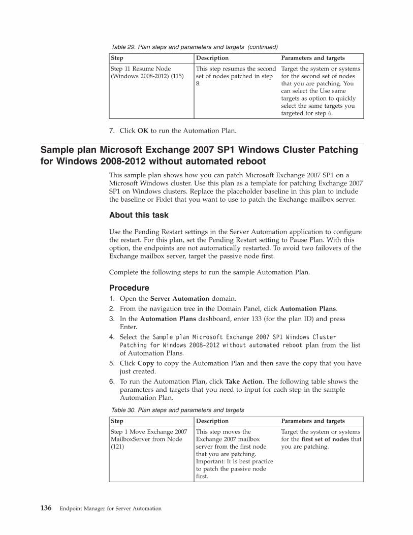
Table 29. Plan steps and parameters and targets (continued)
Step Description Parameters and targets
Step 11 Resume Node(Windows 2008-2012) (115)
This step resumes the secondset of nodes patched in step8.
Target the system or systemsfor the second set of nodesthat you are patching. Youcan select the Use sametargets as option to quicklyselect the same targets youtargeted for step 6.
7. Click OK to run the Automation Plan.
Sample plan Microsoft Exchange 2007 SP1 Windows Cluster Patchingfor Windows 2008-2012 without automated reboot
This sample plan shows how you can patch Microsoft Exchange 2007 SP1 on aMicrosoft Windows cluster. Use this plan as a template for patching Exchange 2007SP1 on Windows clusters. Replace the placeholder baseline in this plan to includethe baseline or Fixlet that you want to use to patch the Exchange mailbox server.
About this task
Use the Pending Restart settings in the Server Automation application to configurethe restart. For this plan, set the Pending Restart setting to Pause Plan. With thisoption, the endpoints are not automatically restarted. To avoid two failovers of theExchange mailbox server, target the passive node first.
Complete the following steps to run the sample Automation Plan.
Procedure1. Open the Server Automation domain.2. From the navigation tree in the Domain Panel, click Automation Plans.3. In the Automation Plans dashboard, enter 133 (for the plan ID) and press
Enter.4. Select the Sample plan Microsoft Exchange 2007 SP1 Windows Cluster
Patching for Windows 2008-2012 without automated reboot plan from the listof Automation Plans.
5. Click Copy to copy the Automation Plan and then save the copy that you havejust created.
6. To run the Automation Plan, click Take Action. The following table shows theparameters and targets that you need to input for each step in the sampleAutomation Plan.
Table 30. Plan steps and parameters and targets
Step Description Parameters and targets
Step 1 Move Exchange 2007MailboxServer from Node(121)
This step moves theExchange 2007 mailboxserver from the first nodethat you are patching.Important: It is best practiceto patch the passive nodefirst.
Target the system or systemsfor the first set of nodes thatyou are patching.
136 Endpoint Manager for Server Automation
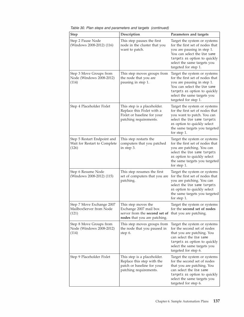
Table 30. Plan steps and parameters and targets (continued)
Step Description Parameters and targets
Step 2 Pause Node(Windows 2008-2012) (116)
This step pauses the firstnode in the cluster that youwant to patch.
Target the system or systemsfor the first set of nodes thatyou are pausing in step 1.You can select the Use sametargets as option to quicklyselect the same targets youtargeted for step 1.
Step 3 Move Groups fromNode (Windows 2008-2012)(114)
This step moves groups fromthe node that you arepausing in step 1.
Target the system or systemsfor the first set of nodes thatyou are pausing in step 1.You can select the Use sametargets as option to quicklyselect the same targets youtargeted for step 1.
Step 4 Placeholder Fixlet This step is a placeholder.Replace this Fixlet with aFixlet or baseline for yourpatching requirements.
Target the system or systemsfor the first set of nodes thatyou want to patch. You canselect the Use same targetsas option to quickly selectthe same targets you targetedfor step 1.
Step 5 Restart Endpoint andWait for Restart to Complete(126)
This step restarts thecomputers that you patchedin step 3.
Target the system or systemsfor the first set of nodes thatyou are patching. You canselect the Use same targetsas option to quickly selectthe same targets you targetedfor step 1.
Step 6 Resume Node(Windows 2008-2012) (115)
This step resumes the firstset of computers that you arepatching.
Target the system or systemsfor the first set of nodes thatyou are patching. You canselect the Use same targetsas option to quickly selectthe same targets you targetedfor step 1.
Step 7 Move Exchange 2007MailboxServer from Node(121)
This step moves theExchange 2007 mail boxserver from the second set ofnodes that you are patching.
Target the system or systemsfor the second set of nodesthat you are patching.
Step 8 Move Groups fromNode (Windows 2008-2012)(114)
This step moves groups fromthe node that you paused instep 6.
Target the system or systemsfor the second set of nodesthat you are patching. Youcan select the Use sametargets as option to quicklyselect the same targets youtargeted for step 6.
Step 9 Placeholder Fixlet This step is a placeholder.Replace this step with thepatch or baseline for yourpatching requirements.
Target the system or systemsfor the second set of nodesthat you are patching. Youcan select the Use sametargets as option to quicklyselect the same targets youtargeted for step 6.
Chapter 6. Sample Automation Plans 137
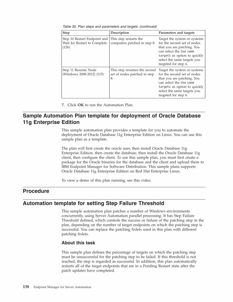
Table 30. Plan steps and parameters and targets (continued)
Step Description Parameters and targets
Step 10 Restart Endpoint andWait for Restart to Complete(126)
This step restarts thecomputers patched in step 8.
Target the system or systemsfor the second set of nodesthat you are patching. Youcan select the Use sametargets as option to quicklyselect the same targets youtargeted for step 6.
Step 11 Resume Node(Windows 2008-2012) (115)
This step resumes the secondset of nodes patched in step8.
Target the system or systemsfor the second set of nodesthat you are patching. Youcan select the Use sametargets as option to quicklyselect the same targets youtargeted for step 6.
7. Click OK to run the Automation Plan.
Sample Automation Plan template for deployment of Oracle Database11g Enterprise Edition
This sample automation plan provides a template for you to automate thedeployment of Oracle Database 11g Enterprise Edition on Linux. You can use thissample plan as a template.
The plan will first create the oracle user, then install Oracle Database 11gEnterprise Edition, then create the database, then install the Oracle Database 11gclient, then configure the client. To use this sample plan, you must first create apackage for the Oracle binaries for the database and the client and upload them toIBM Endpoint Manager for Software Distribution. This sample plans supportsOracle Database 11g Enterprise Edition on Red Hat Enterprise Linux.
To view a demo of this plan running, see this video.
Procedure
Automation template for setting Step Failure ThresholdThis sample automation plan patches a number of Windows environmentsconcurrently, using Server Automation parallel processing. It has Step FailureThreshold defined, which controls the success or failure of the patching step in theplan, depending on the number of target endpoints on which the patching step issuccessful. You can replace the patching fixlets used in this plan with differentpatching fixlets.
About this task
This sample plan defines the percentage of targets on which the patching stepmust be unsuccessful for the patching step to be failed. If this threshold is notreached, the step is regarded as successful. In addition, this plan automaticallyrestarts all of the target endpoints that are in a Pending Restart state after thepatch updates have completed.
138 Endpoint Manager for Server Automation
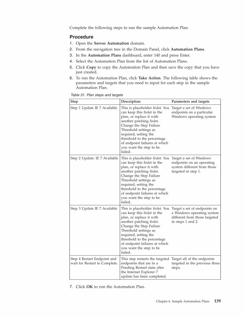
Complete the following steps to run the sample Automation Plan.
Procedure1. Open the Server Automation domain.2. From the navigation tree in the Domain Panel, click Automation Plans.3. In the Automation Plans dashboard, enter 140 and press Enter.4. Select the Automation Plan from the list of Automation Plans.5. Click Copy to copy the Automation Plan and then save the copy that you have
just created.6. To run the Automation Plan, click Take Action. The following table shows the
parameters and targets that you need to input for each step in the sampleAutomation Plan.
Table 31. Plan steps and targets
Step Description Parameters and targets
Step 1 Update IE 7 Available This is placeholder fixlet. Youcan keep this fixlet in theplan, or replace it withanother patching fixlet.Change the Step FailureThreshold settings asrequired, setting thethreshold to the percentageof endpoint failures at whichyou want the step to befailed.
Target a set of Windowsendpoints on a particularWindows operating system
Step 2 Update: IE 7 Available This is placeholder fixlet. Youcan keep this fixlet in theplan, or replace it withanother patching fixlet.Change the Step FailureThreshold settings asrequired, setting thethreshold to the percentageof endpoint failures at whichyou want the step to befailed.
Target a set of Windowsendpoints on an operatingsystem different from thosetargeted in step 1.
Step 3 Update IE 7 Available This is placeholder fixlet. Youcan keep this fixlet in theplan, or replace it withanother patching fixlet.Change the Step FailureThreshold settings asrequired, setting thethreshold to the percentageof endpoint failures at whichyou want the step to befailed.
Target a set of endpoints ona Windows operating systemdifferent from those targetedin steps 1 and 2.
Step 4 Restart Endpoint andwait for Restart to Complete.
This step restarts the targetedendpoints that are in aPending Restart state afterthe Internet Explorer 7update has been completed.
Target all of the endpointstargeted in the previous threesteps.
7. Click OK to run the Automation Plan.
Chapter 6. Sample Automation Plans 139
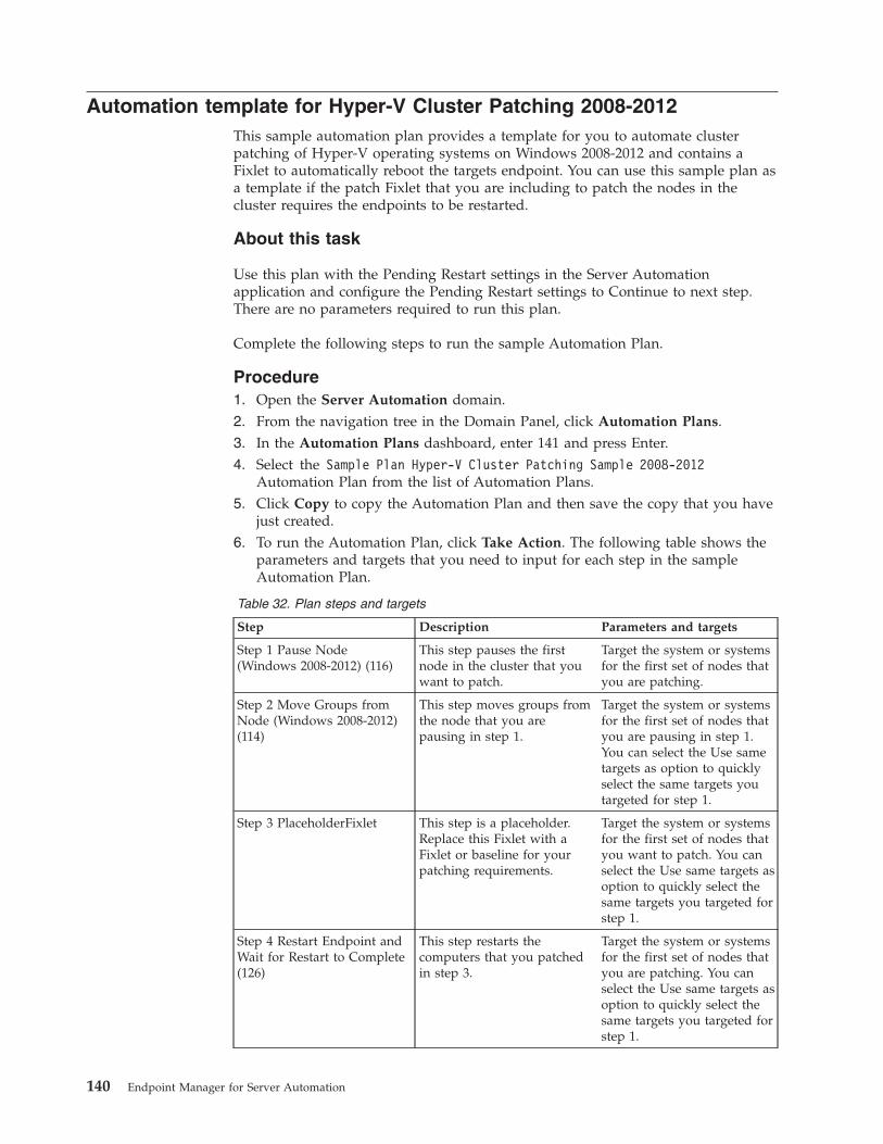
Automation template for Hyper-V Cluster Patching 2008-2012This sample automation plan provides a template for you to automate clusterpatching of Hyper-V operating systems on Windows 2008-2012 and contains aFixlet to automatically reboot the targets endpoint. You can use this sample plan asa template if the patch Fixlet that you are including to patch the nodes in thecluster requires the endpoints to be restarted.
About this task
Use this plan with the Pending Restart settings in the Server Automationapplication and configure the Pending Restart settings to Continue to next step.There are no parameters required to run this plan.
Complete the following steps to run the sample Automation Plan.
Procedure1. Open the Server Automation domain.2. From the navigation tree in the Domain Panel, click Automation Plans.3. In the Automation Plans dashboard, enter 141 and press Enter.4. Select the Sample Plan Hyper-V Cluster Patching Sample 2008-2012
Automation Plan from the list of Automation Plans.5. Click Copy to copy the Automation Plan and then save the copy that you have
just created.6. To run the Automation Plan, click Take Action. The following table shows the
parameters and targets that you need to input for each step in the sampleAutomation Plan.
Table 32. Plan steps and targets
Step Description Parameters and targets
Step 1 Pause Node(Windows 2008-2012) (116)
This step pauses the firstnode in the cluster that youwant to patch.
Target the system or systemsfor the first set of nodes thatyou are patching.
Step 2 Move Groups fromNode (Windows 2008-2012)(114)
This step moves groups fromthe node that you arepausing in step 1.
Target the system or systemsfor the first set of nodes thatyou are pausing in step 1.You can select the Use sametargets as option to quicklyselect the same targets youtargeted for step 1.
Step 3 PlaceholderFixlet This step is a placeholder.Replace this Fixlet with aFixlet or baseline for yourpatching requirements.
Target the system or systemsfor the first set of nodes thatyou want to patch. You canselect the Use same targets asoption to quickly select thesame targets you targeted forstep 1.
Step 4 Restart Endpoint andWait for Restart to Complete(126)
This step restarts thecomputers that you patchedin step 3.
Target the system or systemsfor the first set of nodes thatyou are patching. You canselect the Use same targets asoption to quickly select thesame targets you targeted forstep 1.
140 Endpoint Manager for Server Automation
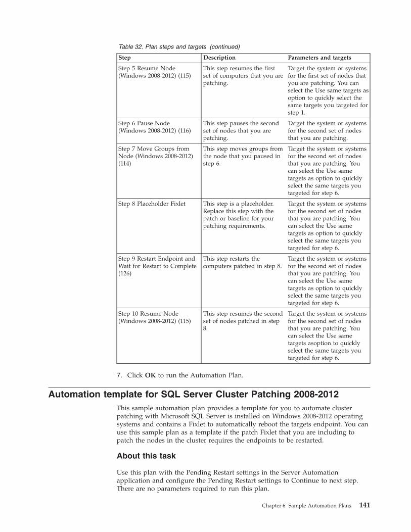
Table 32. Plan steps and targets (continued)
Step Description Parameters and targets
Step 5 Resume Node(Windows 2008-2012) (115)
This step resumes the firstset of computers that you arepatching.
Target the system or systemsfor the first set of nodes thatyou are patching. You canselect the Use same targets asoption to quickly select thesame targets you targeted forstep 1.
Step 6 Pause Node(Windows 2008-2012) (116)
This step pauses the secondset of nodes that you arepatching.
Target the system or systemsfor the second set of nodesthat you are patching.
Step 7 Move Groups fromNode (Windows 2008-2012)(114)
This step moves groups fromthe node that you paused instep 6.
Target the system or systemsfor the second set of nodesthat you are patching. Youcan select the Use sametargets as option to quicklyselect the same targets youtargeted for step 6.
Step 8 Placeholder Fixlet This step is a placeholder.Replace this step with thepatch or baseline for yourpatching requirements.
Target the system or systemsfor the second set of nodesthat you are patching. Youcan select the Use sametargets as option to quicklyselect the same targets youtargeted for step 6.
Step 9 Restart Endpoint andWait for Restart to Complete(126)
This step restarts thecomputers patched in step 8.
Target the system or systemsfor the second set of nodesthat you are patching. Youcan select the Use sametargets as option to quicklyselect the same targets youtargeted for step 6.
Step 10 Resume Node(Windows 2008-2012) (115)
This step resumes the secondset of nodes patched in step8.
Target the system or systemsfor the second set of nodesthat you are patching. Youcan select the Use sametargets asoption to quicklyselect the same targets youtargeted for step 6.
7. Click OK to run the Automation Plan.
Automation template for SQL Server Cluster Patching 2008-2012This sample automation plan provides a template for you to automate clusterpatching with Microsoft SQL Server is installed on Windows 2008-2012 operatingsystems and contains a Fixlet to automatically reboot the targets endpoint. You canuse this sample plan as a template if the patch Fixlet that you are including topatch the nodes in the cluster requires the endpoints to be restarted.
About this task
Use this plan with the Pending Restart settings in the Server Automationapplication and configure the Pending Restart settings to Continue to next step.There are no parameters required to run this plan.
Chapter 6. Sample Automation Plans 141
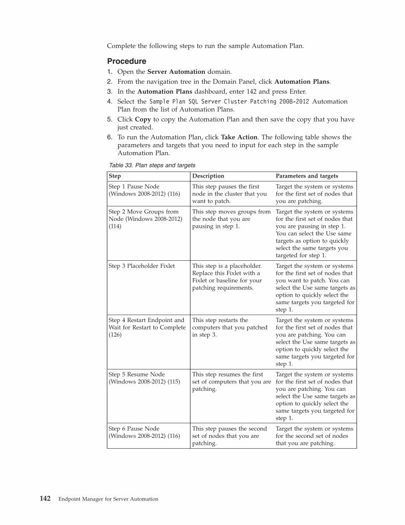
Complete the following steps to run the sample Automation Plan.
Procedure1. Open the Server Automation domain.2. From the navigation tree in the Domain Panel, click Automation Plans.3. In the Automation Plans dashboard, enter 142 and press Enter.4. Select the Sample Plan SQL Server Cluster Patching 2008-2012 Automation
Plan from the list of Automation Plans.5. Click Copy to copy the Automation Plan and then save the copy that you have
just created.6. To run the Automation Plan, click Take Action. The following table shows the
parameters and targets that you need to input for each step in the sampleAutomation Plan.
Table 33. Plan steps and targets
Step Description Parameters and targets
Step 1 Pause Node(Windows 2008-2012) (116)
This step pauses the firstnode in the cluster that youwant to patch.
Target the system or systemsfor the first set of nodes thatyou are patching.
Step 2 Move Groups fromNode (Windows 2008-2012)(114)
This step moves groups fromthe node that you arepausing in step 1.
Target the system or systemsfor the first set of nodes thatyou are pausing in step 1.You can select the Use sametargets as option to quicklyselect the same targets youtargeted for step 1.
Step 3 Placeholder Fixlet This step is a placeholder.Replace this Fixlet with aFixlet or baseline for yourpatching requirements.
Target the system or systemsfor the first set of nodes thatyou want to patch. You canselect the Use same targets asoption to quickly select thesame targets you targeted forstep 1.
Step 4 Restart Endpoint andWait for Restart to Complete(126)
This step restarts thecomputers that you patchedin step 3.
Target the system or systemsfor the first set of nodes thatyou are patching. You canselect the Use same targets asoption to quickly select thesame targets you targeted forstep 1.
Step 5 Resume Node(Windows 2008-2012) (115)
This step resumes the firstset of computers that you arepatching.
Target the system or systemsfor the first set of nodes thatyou are patching. You canselect the Use same targets asoption to quickly select thesame targets you targeted forstep 1.
Step 6 Pause Node(Windows 2008-2012) (116)
This step pauses the secondset of nodes that you arepatching.
Target the system or systemsfor the second set of nodesthat you are patching.
142 Endpoint Manager for Server Automation
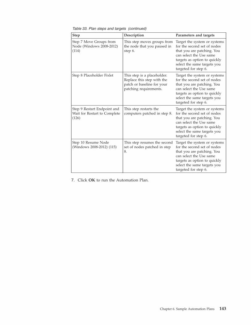
Table 33. Plan steps and targets (continued)
Step Description Parameters and targets
Step 7 Move Groups fromNode (Windows 2008-2012)(114)
This step moves groups fromthe node that you paused instep 6.
Target the system or systemsfor the second set of nodesthat you are patching. Youcan select the Use sametargets as option to quicklyselect the same targets youtargeted for step 6.
Step 8 Placeholder Fixlet This step is a placeholder.Replace this step with thepatch or baseline for yourpatching requirements.
Target the system or systemsfor the second set of nodesthat you are patching. Youcan select the Use sametargets as option to quicklyselect the same targets youtargeted for step 6.
Step 9 Restart Endpoint andWait for Restart to Complete(126)
This step restarts thecomputers patched in step 8.
Target the system or systemsfor the second set of nodesthat you are patching. Youcan select the Use sametargets as option to quicklyselect the same targets youtargeted for step 6.
Step 10 Resume Node(Windows 2008-2012) (115)
This step resumes the secondset of nodes patched in step8.
Target the system or systemsfor the second set of nodesthat you are patching. Youcan select the Use sametargets as option to quicklyselect the same targets youtargeted for step 6.
7. Click OK to run the Automation Plan.
Chapter 6. Sample Automation Plans 143

144 Endpoint Manager for Server Automation
Chapter 7. Server Automation content
Server Automation provides content that you can use to automate processes andsoftware deployment.
Patching Microsoft Windows clustersYou can use Server Automation to automate Microsoft Windows cluster patching.Server Automation contains preconfigured Fixlets that allow you to patchMicrosoft Windows clusters.
The Server Automation cluster patching Fixlets support patching general MicrosoftWindows clusters. For example, you can use the Server Automation Fixlets forpatching scenarios such as Microsoft SQL Server cluster patching.
Patching Microsoft Windows clustersYou can patch Windows clusters using Server Automation Fixlets. The procedureto patch Windows clusters involves running a Fixlet to pause the node that you arepatching. You then run another Fixlet to move any groups on the node to anothernode. You can then patch the node and when you have completed the patching,you run a Fixlet to resume the node. The Fixlets to pause and resume the nodesare operating system-specific and the supported operating systems are described inthe Fixlet descriptions.
Before you begin
The Windows Cluster control scripts must be installed on the target nodes in thecluster. You can install these scripts by running the 110 Install Windows ClusterControl Application Fixlet.
About this task
The Server Automation cluster patching Fixlets support general MicrosoftWindows clusters, including patching scenarios such as Microsoft SQL Servercluster patching.
The following procedure is designed for use with a cluster set up with a quorumconfigured for the following systems:v DiskWitness only (2012 systems)v NoMajority (Disk Only) (2008 systems)v Standard Quorum (2003 systems)
With this setup, the cluster remains operational as long as at least one of the nodesin the cluster is still running. If the quorum for the cluster is configured in anyother way, ensure that when targeting the nodes in the cluster that half of the totalnodes +1 are operational at any time. For example, if there are 20 nodes in thecluster, 11 nodes (10 +1) nodes must be operational at any one time. If there are 16nodes in the cluster, 9 nodes (8 +1) must be operational at any one time.Otherwise, the cluster stops working. The cluster does not resume functioningcorrectly until more than half the nodes have resumed the cluster service and thecluster is unavailable until this time.Complete the following steps to patch a
145
Windows cluster using the Server Automation Fixlets:
Procedure1. Pause the node or nodes in the cluster that you want to patch. Run Fixlet 112
Pause Node in the Cluster (Windows 2003) to pause the node on Windows2003 and Fixlet 116 Pause Node in the Cluster (Windows 2008-2012) to pausethe node on Windows 2008 and 2012. When running the Fixlet to pause thenode, target each node that you want to pause.
2. Move any groups on the node to another node. Use Fixlet 111 Move Groupsfrom Node in the Cluster (Windows 2003) to move groups on Windows 2003and use Fixlet 114 Move Groups from Node in the Cluster (Windows2008-2012) to move groups on Windows 2008 and 2012.
3. Patch or update the node as required. If you use a Baseline to patch the node,check if the Baseline contains an action script that causes the node to report astatus of Pending Restart, for example, action requires restart. If the nodereturns a Pending Restart status, the system determines this as a wait stateand does not complete the step. To correct this, you must include a restartFixlet as part of the Baseline.
4. Resume the node. To resume on Windows 2003, use Fixlets 113 Resume Node inthe Cluster (Windows 2003). To resume on Windows 2008 or Windows 2012,use Fixlets 115 Resume Node in the Cluster (Windows 2008-2012).
5. Repeat this process for the remaining nodes in the cluster.
Patching Servers running Microsoft Exchange 2010 and 2013(Exchange 2013 SP1 and later) Data Availability Groups
You can use Server Automation Tasks to patch an operating system runningMicrosoft Exchange 2010 and Exchange 2013 (Exchange 2013 SP1 and laterversions) Data availability groups (DAG), while maintaining the DAG availability.You patch the operating system using a number of Tasks and a service. The Tasksautomate the execution of Microsoft Exchange scripts provided with Exchange2010 and Exchange 2013. You run these Tasks in an Automation Plan and you cancombine them with custom Tasks for patching the underlying operating system tofully automate the patching process.
Before you beginv For Exchange 2013, Exchange 2103 Service Pack 1 and newer versions are
supported. All version of Exchange 2010 are supported.v Before running any of the patching steps, the control scripts must be installed.
Use Task 110-Install Windows Cluster Control Application to install thecontrol scripts.
v The IBM Exchange Cluster Manager Service must be installed. Use Task 123Install IBM Exchange Cluster Manager Service to install the service.
v .Net Framework 4.0 must be installed on each node. Use Fixlet 40301 UPDATE:Microsoft .NET Framework 4.0 Available -Site-Patches for Windows to installor update the .Net Framework 4.0 on each node.
About this task
The scripts that are run by your Automation Plan are provided by Microsoft. Formore information about these scripts, see the following Microsoft resources:v http://technet.microsoft.com/en-us/library/ee861125(v=exchg.141).aspxv http://technet.microsoft.com/en-us/library/dd298065(v=exchg.141).aspx
146 Endpoint Manager for Server Automation
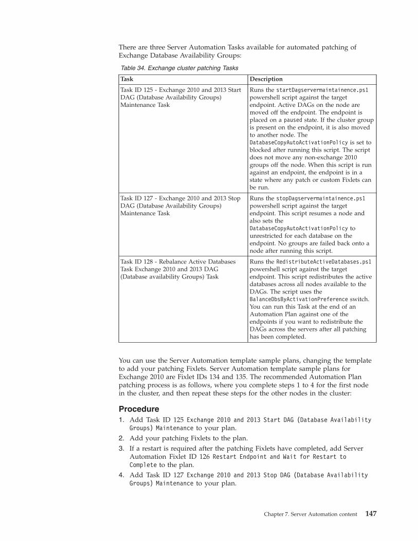
There are three Server Automation Tasks available for automated patching ofExchange Database Availability Groups:
Table 34. Exchange cluster patching Tasks
Task Description
Task ID 125 - Exchange 2010 and 2013 StartDAG (Database Availability Groups)Maintenance Task
Runs the startDagservermaintainence.ps1powershell script against the targetendpoint. Active DAGs on the node aremoved off the endpoint. The endpoint isplaced on a paused state. If the cluster groupis present on the endpoint, it is also movedto another node. TheDatabaseCopyAutoActivationPolicy is set toblocked after running this script. The scriptdoes not move any non-exchange 2010groups off the node. When this script is runagainst an endpoint, the endpoint is in astate where any patch or custom Fixlets canbe run.
Task ID 127 - Exchange 2010 and 2013 StopDAG (Database Availability Groups)Maintenance Task
Runs the stopDagservermaintainence.ps1powershell script against the targetendpoint. This script resumes a node andalso sets theDatabaseCopyAutoActivationPolicy tounrestricted for each database on theendpoint. No groups are failed back onto anode after running this script.
Task ID 128 - Rebalance Active DatabasesTask Exchange 2010 and 2013 DAG(Database availability Groups) Task
Runs the RedistributeActiveDatabases.ps1powershell script against the targetendpoint. This script redistributes the activedatabases across all nodes available to theDAGs. The script uses theBalanceDbsByActivationPreference switch.You can run this Task at the end of anAutomation Plan against one of theendpoints if you want to redistribute theDAGs across the servers after all patchinghas been completed.
You can use the Server Automation template sample plans, changing the templateto add your patching Fixlets. Server Automation template sample plans forExchange 2010 are Fixlet IDs 134 and 135. The recommended Automation Planpatching process is as follows, where you complete steps 1 to 4 for the first nodein the cluster, and then repeat these steps for the other nodes in the cluster:
Procedure1. Add Task ID 125 Exchange 2010 and 2013 Start DAG (Database Availability
Groups) Maintenance to your plan.2. Add your patching Fixlets to the plan.3. If a restart is required after the patching Fixlets have completed, add Server
Automation Fixlet ID 126 Restart Endpoint and Wait for Restart toComplete to the plan.
4. Add Task ID 127 Exchange 2010 and 2013 Stop DAG (Database AvailabilityGroups) Maintenance to your plan.
Chapter 7. Server Automation content 147
5. Add four more steps to the plan, repeating each of steps 1 to 4 for each node inthe cluster.
6. Run the plan.
Results
Monitor the execution of the plan from the Automation Plan Action Statusdashboard. On successful completion of the plan, the Exchange DAGs have beenpatched with the patching Fixlets you included in the plan.
Automating patching of operating system servers in aMicrosoft Hyper-V cluster
You can use Server Automation to automate patching of operating system serversin a Microsoft Hyper-V cluster, without affecting the data availability groupsoperations. Server Automation enables you to automate the patching process usinga number of Tasks which manage the cluster as it is being patched. The Tasksprepare nodes for patching by pausing them and moving all virtual machines,groups, and resources off the nodes. The required patches are then applied to theoperating system as part of the automation flow. After the operating system ispatched, the automation flow restores the nodes to their original pre-patching state.
Before you beginv Control scripts must be installed on each of the endpoints that you are patching.
Use Server Automation Task 110 Install Windows Cluster Control Applicationto install the control scripts.
v The Powershell feature must be installed on each node that you are patching. Bydefault this is installed on all instances of Microsoft Server from 2008 Release 2onwards, except for core installations. For core installations, use the followinglinks to install Powershell:– http://support.microsoft.com/kb/976736– http://technet.microsoft.com/en-us/library/
hh847837.aspx#BKMK_InstallingOnServerCore
About this task
There are two phases in the automated patching flow. In the first phase, one nodeor group of nodes is patched. In the second phase, the second node of group ofnodes is patched. By managing the patching in this way, the cluster remainsoperational at all times. In phase one, you run a sequence of Tasks to manage thepatching of the first node or group of nodes in the cluster. Then you repeat thesesame steps on the second node or nodes in the cluster. The following operatingsystems are supported:v Windows 2012v Windows 2012 Release 2v Windows 2008 Release 2 and later
To automate the patching process, you run an automation plan. The automationplan contains a number of steps, each of which represents a stage in patchingprocess. You can create a new automation plan or modify an existing plan, such asan out-of-the-box sample plan by changing some of the steps.
148 Endpoint Manager for Server Automation
Procedure1. Add Task ID 117 Pre-patching Task for clustered Microsoft HyperVisor
Servers to the plan as step 1 in the plan. When you are running the plan,target the first node or group of nodes in the cluster.This Task performs the following functions:a. Creates a file detailing all groups and virtual machines in the cluster,
including what nodes they are on and the states of each resource in thecluster. If there are empty groups (groups with no resources) in the cluster,a second file is created detailing these groups.
b. Pauses the node.c. Checks to see if there are other nodes available to which to move the virtual
machines. If other nodes are available, virtual machines are moved usingthe method you select (either live migrated or quick migrated). If the virtualmachines are set up to be online only on the current node (no other possibleowners set) the virtual machine is taken offline. If the virtual machine hasother possible owners but these owners are not available, the Task failsbecause it is not possible to move the virtual machine off the node.
d. Moves groups that have other available owners. If no other owners areavailable to take groups, the Task fails. Any groups set up to be online onlyon the current node (only target set as possible owner of the group or atleast one resource in the group) are the taken offline.
e. Takes any empty groups offline.f. Checks to ensure the node is paused and has no active groups remaining
and is a state suitable for patching the server operating system.
Note: This Task does not move any groups that were offline before the Taskwas run.
2. Add the required operating system patching Fixlet, Task, or Baseline as thesecond step in the plan. When you are running the plan, target the first node orgroup of nodes in the cluster.
3. Add Server Automation Task 126 Restart Endpoint and Wait for Restart toComplete to restart the first node or group of nodes in the cluster. When youare running the plan, target the first node or group of nodes in the cluster.
4. Add the post patching Task 129 Post Patching task for Microsoft ServerClusters (Server 2008 R2 onwards including Hyper-V Clusters) to restorethe node or nodes to their original state. After this Task has run successfully,the first node or nodes in the cluster are patched and back up and running.When you are running the plan, target the first node or group of nodes in thecluster.This Task performs the following functions:a. Resumes the node.b. If the cluster detail file is found on the targeted endpoints, the Task checks
this file and moves any virtual machines and groups back on to the node ifthey were moved off the node during patching. The Task then brings backonline any empty groups or groups which had the target node as the onlypossible owner of the group before patching.
5. Add four more steps to the plan, to repeat steps 1 to 4 for the second node orgroup of nodes. For each of these steps, you need to target the second node ornodes in the cluster.
Chapter 7. Server Automation content 149
Patching Microsoft Exchange 2007 on Windows clustersYou can use Server Automation Fixlets to patch a Windows Cluster that is runningMicrosoft Exchange 2007 on Windows Server 2003 or Windows Server 2008. As perindustry standard, patch the passive node first. This avoids moving the Mailboxserver twice in a patching scenario. You add the Server Automation Fixlets into aplan to automate the patching process. You can use Fixlet 121 Move Exchange 2007Mailbox Server from Node to identify the active node as this Fixlet will only berelevant on the node running the Mailbox server.
Before you beginv Before running any of the patching steps the control scripts must be installed.
Use Task 110-Install Windows Cluster Control Application to install thecontrol scripts.
v The IBM Exchange Cluster Manager Service must be installed. Use Task 123Install IBM Exchange Cluster Manager Service to install the service.
v .Net Framework 4.0 must be installed on each node. Use Fixlet 40301 UPDATE:Microsoft .NET Framework 4.0 Available -Site-Patches for Windows to installor update the .Net Framework 4.0 on each node.
About this task
The IBM cluster patch solution works by using a number of Fixlets and a service toenable patching of an Exchange cluster environment. To move an ExchangeMailbox Server from node to node you must be a domain level user. To achievethis a service is installed on each node which runs with the domain levelcredentials. Moving the clustered mailbox is governed by a Microsoft ShellCommand and might not always successfully move the mailbox. For moreinformation, see this Microsoft tech note.
Start the patching process by patching the passive node. Then repeat the procedurefor the active node.
Procedure1. Optional: Use Fixlet 121 Move Exchange 2007 MailboxServer from Node to
move the Mailbox Server from the node.2. Pause the node or nodes in the cluster that you want to patch. Run one of the
following Fixlets:a. Fixlet ID 112 Pause Node for Windows 2003 Servers.b. Fixlet ID 116 Pause Node for Windows 2008 Servers.
3. Move any groups on the node to another node using one of the followingFixlets:a. Fixlet ID 111 Move Groups for Windows 2003 Servers.b. Fixlet ID 114 Move Groups for Windows 2008 Servers.
4. Patch or update the node as required. If you use a Baseline to patch the node,check if the Baseline contains an action script that causes the node to report astatus of Pending Restart, for example, action requires restart. If the nodereturns a Pending Restart status, the system determines this as a wait stateand does not complete the step. To correct this, you must include a restartFixlet as part of the Baseline.
5. Resume the node using one of the following Fixlets, depending on youroperating system:a. Fixlet ID 113 Resume Node for Windows 2003 Servers
150 Endpoint Manager for Server Automation
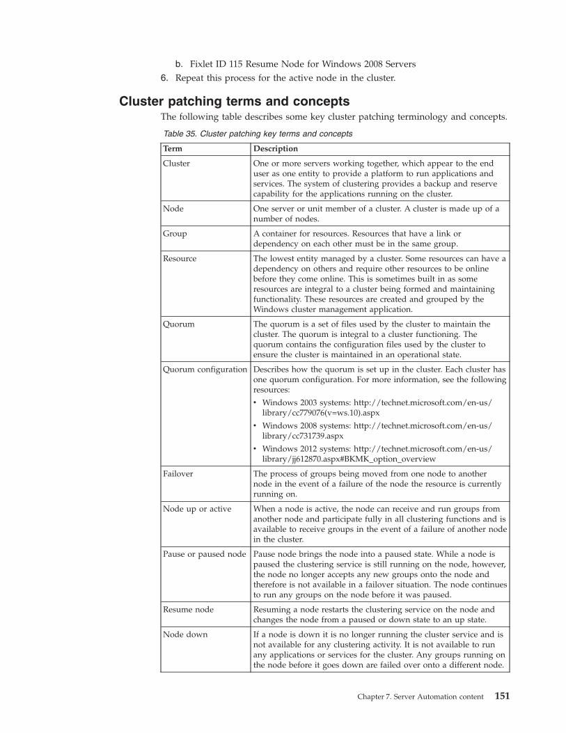
b. Fixlet ID 115 Resume Node for Windows 2008 Servers6. Repeat this process for the active node in the cluster.
Cluster patching terms and conceptsThe following table describes some key cluster patching terminology and concepts.
Table 35. Cluster patching key terms and concepts
Term Description
Cluster One or more servers working together, which appear to the enduser as one entity to provide a platform to run applications andservices. The system of clustering provides a backup and reservecapability for the applications running on the cluster.
Node One server or unit member of a cluster. A cluster is made up of anumber of nodes.
Group A container for resources. Resources that have a link ordependency on each other must be in the same group.
Resource The lowest entity managed by a cluster. Some resources can have adependency on others and require other resources to be onlinebefore they come online. This is sometimes built in as someresources are integral to a cluster being formed and maintainingfunctionality. These resources are created and grouped by theWindows cluster management application.
Quorum The quorum is a set of files used by the cluster to maintain thecluster. The quorum is integral to a cluster functioning. Thequorum contains the configuration files used by the cluster toensure the cluster is maintained in an operational state.
Quorum configuration Describes how the quorum is set up in the cluster. Each cluster hasone quorum configuration. For more information, see the followingresources:
v Windows 2003 systems: http://technet.microsoft.com/en-us/library/cc779076(v=ws.10).aspx
v Windows 2008 systems: http://technet.microsoft.com/en-us/library/cc731739.aspx
v Windows 2012 systems: http://technet.microsoft.com/en-us/library/jj612870.aspx#BKMK_option_overview
Failover The process of groups being moved from one node to anothernode in the event of a failure of the node the resource is currentlyrunning on.
Node up or active When a node is active, the node can receive and run groups fromanother node and participate fully in all clustering functions and isavailable to receive groups in the event of a failure of another nodein the cluster.
Pause or paused node Pause node brings the node into a paused state. While a node ispaused the clustering service is still running on the node, however,the node no longer accepts any new groups onto the node andtherefore is not available in a failover situation. The node continuesto run any groups on the node before it was paused.
Resume node Resuming a node restarts the clustering service on the node andchanges the node from a paused or down state to an up state.
Node down If a node is down it is no longer running the cluster service and isnot available for any clustering activity. It is not available to runany applications or services for the cluster. Any groups running onthe node before it goes down are failed over onto a different node.
Chapter 7. Server Automation content 151
Table 35. Cluster patching key terms and concepts (continued)
Term Description
Move group A move group command moves groups from the node thecommand is run against to another available node in the cluster.Other nodes must be available for this command to worksuccessful.
Server Automation middleware contentYou can use the IBM Endpoint Manager for Server Automation middleware Tasksto automate the deployment of middleware applications. You can include theseTasks as steps in your Automation Plans.
IBM Endpoint Manager V9.1 supports the SHA-256 algorithm. Depending on theconfiguration you have set for the SHA algorithm in IBM Endpoint Manager V9.1,the Server Automation middleware Tasks show different options. If you haveenabled SHA-256 in IBM Endpoint Manager V9.1, you must use SHA-256 in theServer Automation middleware Tasks. If you have not enabled SHA-256 in IBMEndpoint Manager V9.1, you can use SHA-1 in the Server Automation middlewareTasks.
Before you begin using the Tasks, ensure that you read the prerequisite informationdescribed here.
PrerequisitesTo use the Server Automation middleware Fixlets, you must create packagescontaining the specific version of the software that you are deploying. You createthe packages in the Manage Software Distribution dashboard in IBM EndpointManager. This allows the Fixlets to access the software that you are deploying. Youmust also configure the IBM Endpoint Manager server to allow dynamicdownloads. You need access to the Systems Lifecycle domain and the SoftwareDistribution site.
For each Fixlet, you must create a corresponding package for the middlewarecomponent that you want to deploy and add it to the Manage SoftwareDistribution dashboard in IBM Endpoint Manager. Then when you are runningthe Fixlet, you specify the URL for the package that you created. The Fixlet canthen download the package and deploy the contents.
Important: When you are creating packages and adding them to the ManageSoftware Distribution dashboard, you need to extract the contents of ZIP filesbefore you upload them to the Manage Software Distribution dashboard. If youupload ZIP files without first extracting the contents, the Fixlets are unable todeploy the middleware correctly.
Important: When uploading binary files the Manage Software Distributiondashboard, remove any hyphens or special characters from the binary name. Onlythe following characters work correctly when uploading packages to the ManageSoftware Distribution dashboard:v Uppercase or lowercase letters from a to z.v Numerical values from 0 to 9.v Underscore _v Period .
152 Endpoint Manager for Server Automation
If you include hyphens or any other multi-byte characters other than those listedabove, the file name of the uploaded package is renamed to its sha 1 value and thedownload does not work. Only single byte characters work correctly.
For each file to be downloaded in IBM Endpoint Manager, there are three requiredfields.
URL The URL from which the file can be downloaded. This is generally http,https, or ftp.
SHA-1The SHA-1 is a generated checksum to ensure that the downloaded file iscorrect.
Note:
IBM Endpoint Manager V9.1 supports the SHA-256 algorithm. Dependingon the configuration you have set for the SHA algorithm in IBM EndpointManager V9.1, the Server Automation middleware Tasks show differentoptions. If you have enabled SHA-256 in IBM Endpoint Manager V9.1, youmust use SHA-256 in the Server Automation middleware Tasks. If youhave not enabled SHA-256 in IBM Endpoint Manager V9.1, you can useSHA-1 in the Server Automation middleware Tasks.
Size The size of the file in bytes is used with the SHA-1 to validate the file iscorrect.
You can use the Manage Software Distribution dashboard to download therequired files. When the files are downloaded, select the correct binary file fromthe Select a binary file list in the Fixlet description to populate the URL, SHA-1,and Size fields. To use the Manage Software Distribution function, you mustconfigure the IBM Endpoint Manager server for dynamic downloads.
Note: For binary files larger than 2 GB, you might experience issues. Ensure thatthese files are successfully archived in the Manage Software Distributiondashboard. Large files might display in the Fixlet Select a binary file list even ifthey are not fully uploaded.
Manage Software Distribution dashboard
You can download the required files to the IBM Endpoint Manager Server Uploadsdirectory, by clicking Manage Software Distribution in the middleware FixletDescription tab. Specific instructions about how to do this are included in theDescription tab of each Fixlet. The Manage Software Distribution dashboard ispart of the Systems Lifecycle domain and the Software Distribution site. To use theManage Software Distribution dashboard, you must acquire the SoftwareDistribution site. For information about setting up the Manage SoftwareDistribution dashboard, see Software Distribution dashboards Setup.
To download the required files, you must create a package and add one or morefiles to the package. For information about creating a Software Distributionspackage and adding files to packages, see Managing Packages.
Chapter 7. Server Automation content 153
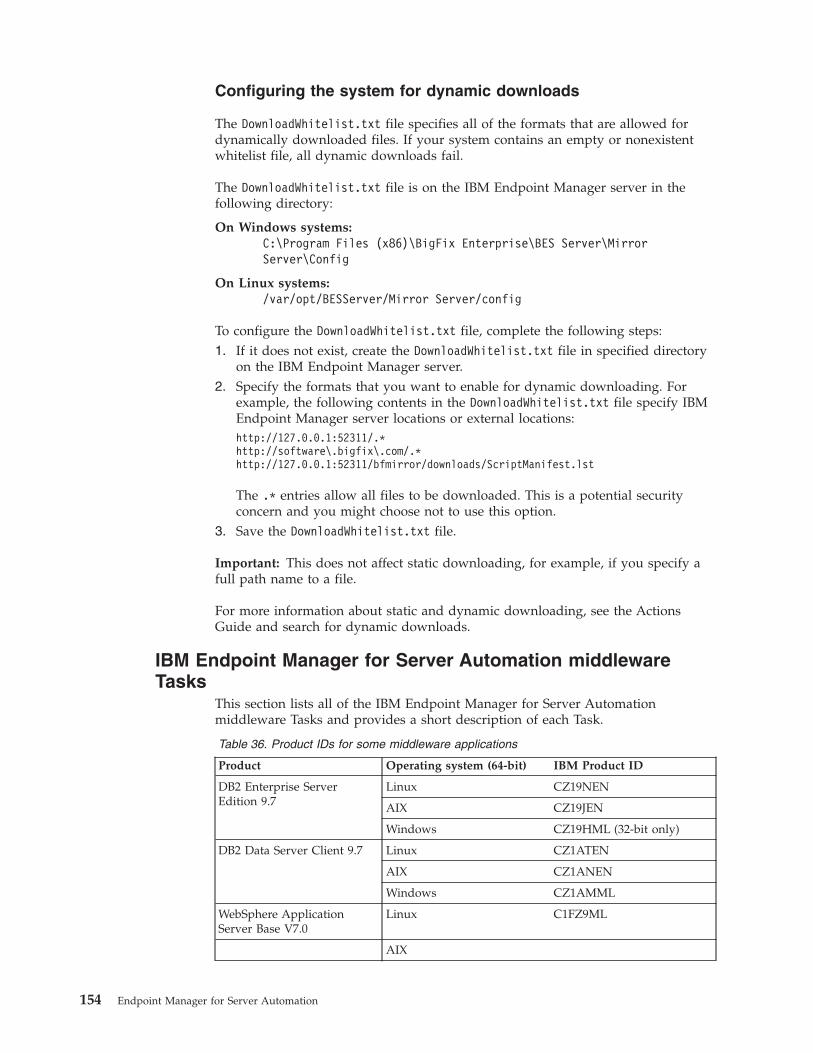
Configuring the system for dynamic downloads
The DownloadWhitelist.txt file specifies all of the formats that are allowed fordynamically downloaded files. If your system contains an empty or nonexistentwhitelist file, all dynamic downloads fail.
The DownloadWhitelist.txt file is on the IBM Endpoint Manager server in thefollowing directory:
On Windows systems:C:\Program Files (x86)\BigFix Enterprise\BES Server\MirrorServer\Config
On Linux systems:/var/opt/BESServer/Mirror Server/config
To configure the DownloadWhitelist.txt file, complete the following steps:1. If it does not exist, create the DownloadWhitelist.txt file in specified directory
on the IBM Endpoint Manager server.2. Specify the formats that you want to enable for dynamic downloading. For
example, the following contents in the DownloadWhitelist.txt file specify IBMEndpoint Manager server locations or external locations:http://127.0.0.1:52311/.*http://software\.bigfix\.com/.*http://127.0.0.1:52311/bfmirror/downloads/ScriptManifest.lst
The .* entries allow all files to be downloaded. This is a potential securityconcern and you might choose not to use this option.
3. Save the DownloadWhitelist.txt file.
Important: This does not affect static downloading, for example, if you specify afull path name to a file.
For more information about static and dynamic downloading, see the ActionsGuide and search for dynamic downloads.
IBM Endpoint Manager for Server Automation middlewareTasks
This section lists all of the IBM Endpoint Manager for Server Automationmiddleware Tasks and provides a short description of each Task.
Table 36. Product IDs for some middleware applications
Product Operating system (64-bit) IBM Product ID
DB2 Enterprise ServerEdition 9.7
Linux CZ19NEN
AIX CZ19JEN
Windows CZ19HML (32-bit only)
DB2 Data Server Client 9.7 Linux CZ1ATEN
AIX CZ1ANEN
Windows CZ1AMML
WebSphere ApplicationServer Base V7.0
Linux C1FZ9ML
AIX
154 Endpoint Manager for Server Automation
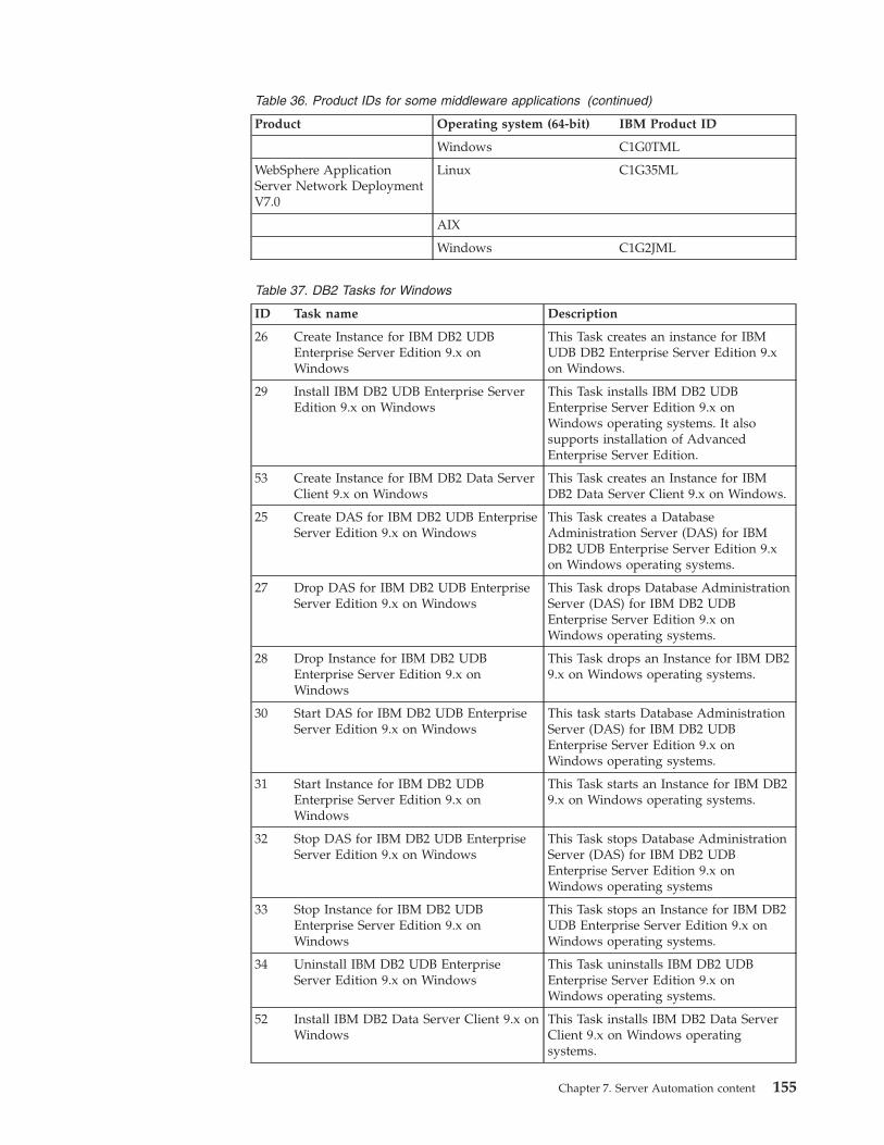
Table 36. Product IDs for some middleware applications (continued)
Product Operating system (64-bit) IBM Product ID
Windows C1G0TML
WebSphere ApplicationServer Network DeploymentV7.0
Linux C1G35ML
AIX
Windows C1G2JML
Table 37. DB2 Tasks for Windows
ID Task name Description
26 Create Instance for IBM DB2 UDBEnterprise Server Edition 9.x onWindows
This Task creates an instance for IBMUDB DB2 Enterprise Server Edition 9.xon Windows.
29 Install IBM DB2 UDB Enterprise ServerEdition 9.x on Windows
This Task installs IBM DB2 UDBEnterprise Server Edition 9.x onWindows operating systems. It alsosupports installation of AdvancedEnterprise Server Edition.
53 Create Instance for IBM DB2 Data ServerClient 9.x on Windows
This Task creates an Instance for IBMDB2 Data Server Client 9.x on Windows.
25 Create DAS for IBM DB2 UDB EnterpriseServer Edition 9.x on Windows
This Task creates a DatabaseAdministration Server (DAS) for IBMDB2 UDB Enterprise Server Edition 9.xon Windows operating systems.
27 Drop DAS for IBM DB2 UDB EnterpriseServer Edition 9.x on Windows
This Task drops Database AdministrationServer (DAS) for IBM DB2 UDBEnterprise Server Edition 9.x onWindows operating systems.
28 Drop Instance for IBM DB2 UDBEnterprise Server Edition 9.x onWindows
This Task drops an Instance for IBM DB29.x on Windows operating systems.
30 Start DAS for IBM DB2 UDB EnterpriseServer Edition 9.x on Windows
This task starts Database AdministrationServer (DAS) for IBM DB2 UDBEnterprise Server Edition 9.x onWindows operating systems.
31 Start Instance for IBM DB2 UDBEnterprise Server Edition 9.x onWindows
This Task starts an Instance for IBM DB29.x on Windows operating systems.
32 Stop DAS for IBM DB2 UDB EnterpriseServer Edition 9.x on Windows
This Task stops Database AdministrationServer (DAS) for IBM DB2 UDBEnterprise Server Edition 9.x onWindows operating systems
33 Stop Instance for IBM DB2 UDBEnterprise Server Edition 9.x onWindows
This Task stops an Instance for IBM DB2UDB Enterprise Server Edition 9.x onWindows operating systems.
34 Uninstall IBM DB2 UDB EnterpriseServer Edition 9.x on Windows
This Task uninstalls IBM DB2 UDBEnterprise Server Edition 9.x onWindows operating systems.
52 Install IBM DB2 Data Server Client 9.x onWindows
This Task installs IBM DB2 Data ServerClient 9.x on Windows operatingsystems.
Chapter 7. Server Automation content 155
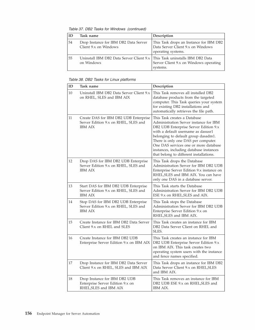
Table 37. DB2 Tasks for Windows (continued)
ID Task name Description
54 Drop Instance for IBM DB2 Data ServerClient 9.x on Windows
This Task drops an Instance for IBM DB2Data Server Client 9.x on Windowsoperating systems.
55 Uninstall IBM DB2 Data Server Client 9.xon Windows
This Task uninstalls IBM DB2 DataServer Client 9.x on Windows operatingsystems.
Table 38. DB2 Tasks for Linux platforms
ID Task name Description
10 Uninstall IBM DB2 Data Server Client 9.xon RHEL, SLES and IBM AIX
This Task removes all installed DB2database products from the targetedcomputer. This Task queries your systemfor existing DB2 installations andautomatically retrieves the file path.
11 Create DAS for IBM DB2 UDB EnterpriseServer Edition 9.x on RHEL, SLES andIBM AIX
This Task creates a DatabaseAdministration Server instance for IBMDB2 UDB Enterprise Server Edition 9.xwith a default username as dasusr1belonging to default group dasadm1.There is only one DAS per computer.One DAS services one or more databaseinstances, including database instancesthat belong to different installations.
12 Drop DAS for IBM DB2 UDB EnterpriseServer Edition 9.x on RHEL, SLES andIBM AIX
This Task drops the DatabaseAdministration Server for IBM DB2 UDBEnterprise Server Edition 9.x instance onRHEL,SLES and IBM AIX. You can haveonly one DAS in a database server.
13 Start DAS for IBM DB2 UDB EnterpriseServer Edition 9.x on RHEL, SLES andIBM AIX
This Task starts the DatabaseAdministration Server for IBM DB2 UDBESE 9.x on RHEL,SLES and AIX.
14 Stop DAS for IBM DB2 UDB EnterpriseServer Edition 9.x on RHEL, SLES andIBM AIX
This Task stops the DatabaseAdministration Server for IBM DB2 UDBEnterprise Server Edition 9.x onRHEL,SLES and IBM AIX.
15 Create Instance for IBM DB2 Data ServerClient 9.x on RHEL and SLES
This Task creates an instance for IBMDB2 Data Server Client on RHEL andSLES.
16 Create Instance for IBM DB2 UDBEnterprise Server Edition 9.x on IBM AIX
This Task creates an instance for IBMDB2 UDB Enterprise Server Edition 9.xon IBM AIX. This task creates twooperating system users with the instanceand fence names specified.
17 Drop Instance for IBM DB2 Data ServerClient 9.x on RHEL, SLES and IBM AIX
This Task drops an instance for IBM DB2Data Server Client 9.x on RHEL,SLESand IBM AIX.
18 Drop Instance for IBM DB2 UDBEnterprise Server Edition 9.x onRHEL,SLES and IBM AIX
This Task removes an instance for IBMDB2 UDB ESE 9.x on RHEL,SLES andIBM AIX.
156 Endpoint Manager for Server Automation
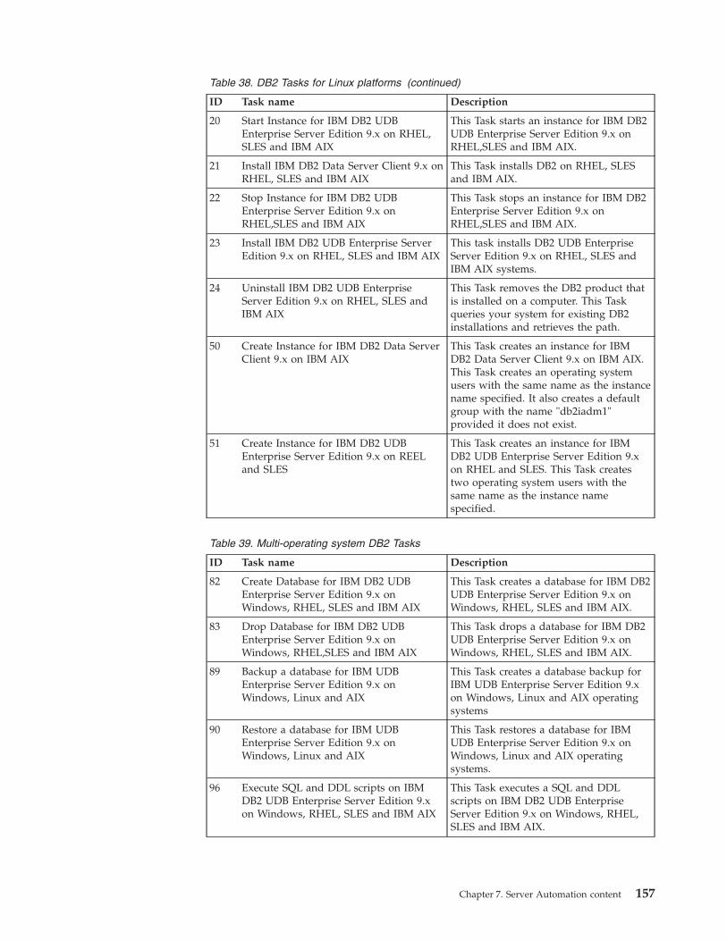
Table 38. DB2 Tasks for Linux platforms (continued)
ID Task name Description
20 Start Instance for IBM DB2 UDBEnterprise Server Edition 9.x on RHEL,SLES and IBM AIX
This Task starts an instance for IBM DB2UDB Enterprise Server Edition 9.x onRHEL,SLES and IBM AIX.
21 Install IBM DB2 Data Server Client 9.x onRHEL, SLES and IBM AIX
This Task installs DB2 on RHEL, SLESand IBM AIX.
22 Stop Instance for IBM DB2 UDBEnterprise Server Edition 9.x onRHEL,SLES and IBM AIX
This Task stops an instance for IBM DB2Enterprise Server Edition 9.x onRHEL,SLES and IBM AIX.
23 Install IBM DB2 UDB Enterprise ServerEdition 9.x on RHEL, SLES and IBM AIX
This task installs DB2 UDB EnterpriseServer Edition 9.x on RHEL, SLES andIBM AIX systems.
24 Uninstall IBM DB2 UDB EnterpriseServer Edition 9.x on RHEL, SLES andIBM AIX
This Task removes the DB2 product thatis installed on a computer. This Taskqueries your system for existing DB2installations and retrieves the path.
50 Create Instance for IBM DB2 Data ServerClient 9.x on IBM AIX
This Task creates an instance for IBMDB2 Data Server Client 9.x on IBM AIX.This Task creates an operating systemusers with the same name as the instancename specified. It also creates a defaultgroup with the name "db2iadm1"provided it does not exist.
51 Create Instance for IBM DB2 UDBEnterprise Server Edition 9.x on REELand SLES
This Task creates an instance for IBMDB2 UDB Enterprise Server Edition 9.xon RHEL and SLES. This Task createstwo operating system users with thesame name as the instance namespecified.
Table 39. Multi-operating system DB2 Tasks
ID Task name Description
82 Create Database for IBM DB2 UDBEnterprise Server Edition 9.x onWindows, RHEL, SLES and IBM AIX
This Task creates a database for IBM DB2UDB Enterprise Server Edition 9.x onWindows, RHEL, SLES and IBM AIX.
83 Drop Database for IBM DB2 UDBEnterprise Server Edition 9.x onWindows, RHEL,SLES and IBM AIX
This Task drops a database for IBM DB2UDB Enterprise Server Edition 9.x onWindows, RHEL, SLES and IBM AIX.
89 Backup a database for IBM UDBEnterprise Server Edition 9.x onWindows, Linux and AIX
This Task creates a database backup forIBM UDB Enterprise Server Edition 9.xon Windows, Linux and AIX operatingsystems
90 Restore a database for IBM UDBEnterprise Server Edition 9.x onWindows, Linux and AIX
This Task restores a database for IBMUDB Enterprise Server Edition 9.x onWindows, Linux and AIX operatingsystems.
96 Execute SQL and DDL scripts on IBMDB2 UDB Enterprise Server Edition 9.xon Windows, RHEL, SLES and IBM AIX
This Task executes a SQL and DDLscripts on IBM DB2 UDB EnterpriseServer Edition 9.x on Windows, RHEL,SLES and IBM AIX.
Chapter 7. Server Automation content 157
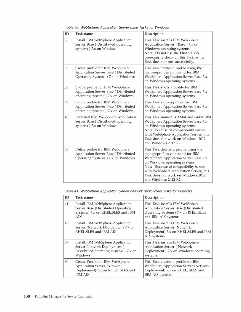
Table 40. WebSphere Application Server base Tasks for Windows
ID Task name Description
36 Install IBM WebSphere ApplicationServer Base ( Distributed operatingsystems ) 7.x on Windows
This Task installs IBM WebSphereApplication Server ( Base ) 7.x onWindows operating systems.Note: Do not use the Disable OSprerequisite check on this Task or theTask does not run successfully.
37 Create profile for IBM WebSphereApplication Server Base ( DistributedOperating Systems ) 7.x on Windows
This Task creates a profile using themanageprofiles command for IBMWebSphere Application Server Base 7.xon Windows operating systems.
38 Start a profile for IBM WebSphereApplication Server Base ( Distributedoperating systems ) 7.x on Windows
This Task starts a profile for IBMWebSphere Application Server Base 7.xon Windows operating systems.
39 Stop a profile for IBM WebSphereApplication Server Base ( Distributedoperating systems ) 7.x on Windows
This Task stops a profile for IBMWebSphere Application Server Base 7.xon Windows operating systems.
40 Uninstall IBM WebSphere ApplicationServer Base ( Distributed operatingsystems ) 7.x on Windows
This Task uninstalls 32-bit and 64-bit IBMWebSphere Application Server Base 7.xon Windows operating systems.Note: Because of compatibility issueswith WebSphere Application Server, thisTask does not work on Windows 2012and Windows 2012 R2.
56 Delete profile for IBM WebSphereApplication Server Base ( DistributedOperating Systems ) 7.x on Windows
This Task deletes a profile using themanageprofiles command for IBMWebSphere Application Server Base 7.xon Windows operating systems.Note: Because of compatibility issueswith WebSphere Application Server, thisTask does not work on Windows 2012and Windows 2012 R2.
Table 41. WebSphere Application Server network deployment tasks for Windows
ID Task name Description
41 Install IBM WebSphere ApplicationServer Base (Distributed OperatingSystems) 7.x on RHEL,SLES and IBMAIX
This Task installs IBM WebSphereApplication Server Base (DistributedOperating Systems) 7.x on RHEL,SLESand IBM AIX systems.
43 Install IBM WebSphere ApplicationServer (Network Deployment) 7.x onRHEL,SLES and IBM AIX
This Task installs IBM WebSphereApplication Server (NetworkDeployment) 7.x on RHEL,SLES and IBMAIX systems.
57 Install IBM WebSphere ApplicationServer Network Deployment (Distributed operating systems ) 7.x onWindows
This Task installs IBM WebSphereApplication Server ( NetworkDeployment ) 7.x on Windows operatingsystems.
60 Create Profile for IBM WebSphereApplication Server (NetworkDeployment) 7.x on RHEL, SLES andIBM AIX
This Task creates a profile for IBMWebSphere Application Server (NetworkDeployment) 7.x on RHEL, SLES andIBM AIX systems.
158 Endpoint Manager for Server Automation
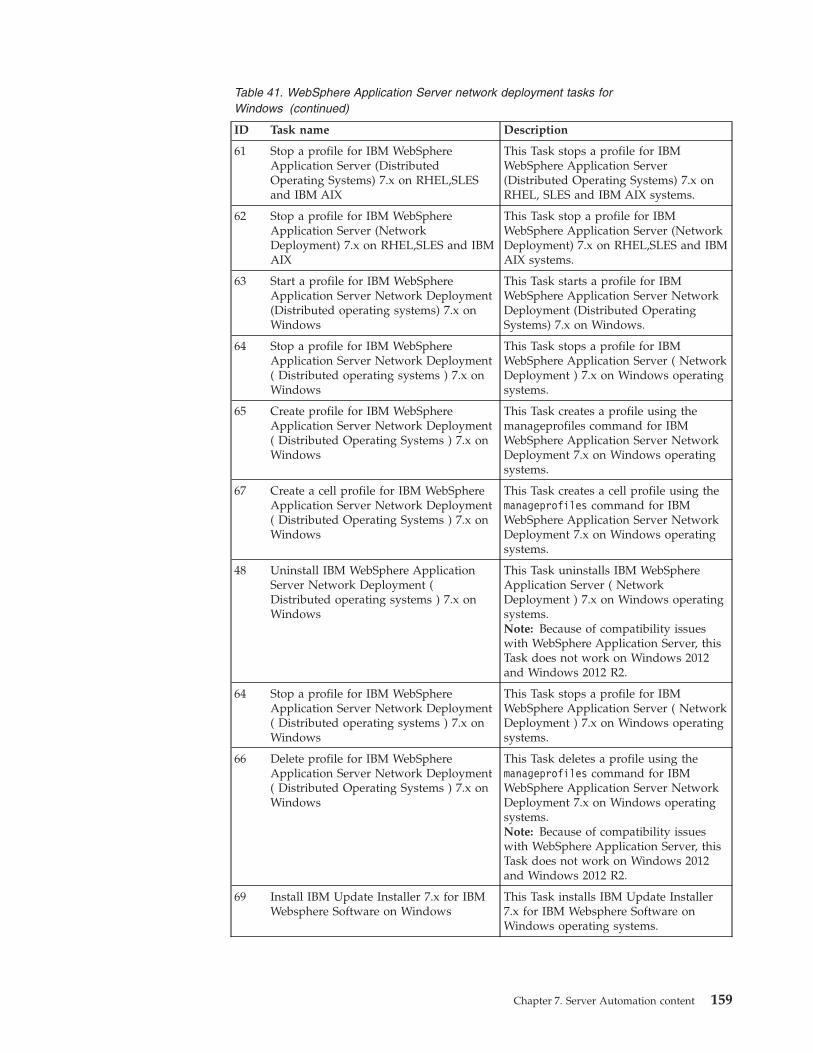
Table 41. WebSphere Application Server network deployment tasks forWindows (continued)
ID Task name Description
61 Stop a profile for IBM WebSphereApplication Server (DistributedOperating Systems) 7.x on RHEL,SLESand IBM AIX
This Task stops a profile for IBMWebSphere Application Server(Distributed Operating Systems) 7.x onRHEL, SLES and IBM AIX systems.
62 Stop a profile for IBM WebSphereApplication Server (NetworkDeployment) 7.x on RHEL,SLES and IBMAIX
This Task stop a profile for IBMWebSphere Application Server (NetworkDeployment) 7.x on RHEL,SLES and IBMAIX systems.
63 Start a profile for IBM WebSphereApplication Server Network Deployment(Distributed operating systems) 7.x onWindows
This Task starts a profile for IBMWebSphere Application Server NetworkDeployment (Distributed OperatingSystems) 7.x on Windows.
64 Stop a profile for IBM WebSphereApplication Server Network Deployment( Distributed operating systems ) 7.x onWindows
This Task stops a profile for IBMWebSphere Application Server ( NetworkDeployment ) 7.x on Windows operatingsystems.
65 Create profile for IBM WebSphereApplication Server Network Deployment( Distributed Operating Systems ) 7.x onWindows
This Task creates a profile using themanageprofiles command for IBMWebSphere Application Server NetworkDeployment 7.x on Windows operatingsystems.
67 Create a cell profile for IBM WebSphereApplication Server Network Deployment( Distributed Operating Systems ) 7.x onWindows
This Task creates a cell profile using themanageprofiles command for IBMWebSphere Application Server NetworkDeployment 7.x on Windows operatingsystems.
48 Uninstall IBM WebSphere ApplicationServer Network Deployment (Distributed operating systems ) 7.x onWindows
This Task uninstalls IBM WebSphereApplication Server ( NetworkDeployment ) 7.x on Windows operatingsystems.Note: Because of compatibility issueswith WebSphere Application Server, thisTask does not work on Windows 2012and Windows 2012 R2.
64 Stop a profile for IBM WebSphereApplication Server Network Deployment( Distributed operating systems ) 7.x onWindows
This Task stops a profile for IBMWebSphere Application Server ( NetworkDeployment ) 7.x on Windows operatingsystems.
66 Delete profile for IBM WebSphereApplication Server Network Deployment( Distributed Operating Systems ) 7.x onWindows
This Task deletes a profile using themanageprofiles command for IBMWebSphere Application Server NetworkDeployment 7.x on Windows operatingsystems.Note: Because of compatibility issueswith WebSphere Application Server, thisTask does not work on Windows 2012and Windows 2012 R2.
69 Install IBM Update Installer 7.x for IBMWebsphere Software on Windows
This Task installs IBM Update Installer7.x for IBM Websphere Software onWindows operating systems.
Chapter 7. Server Automation content 159
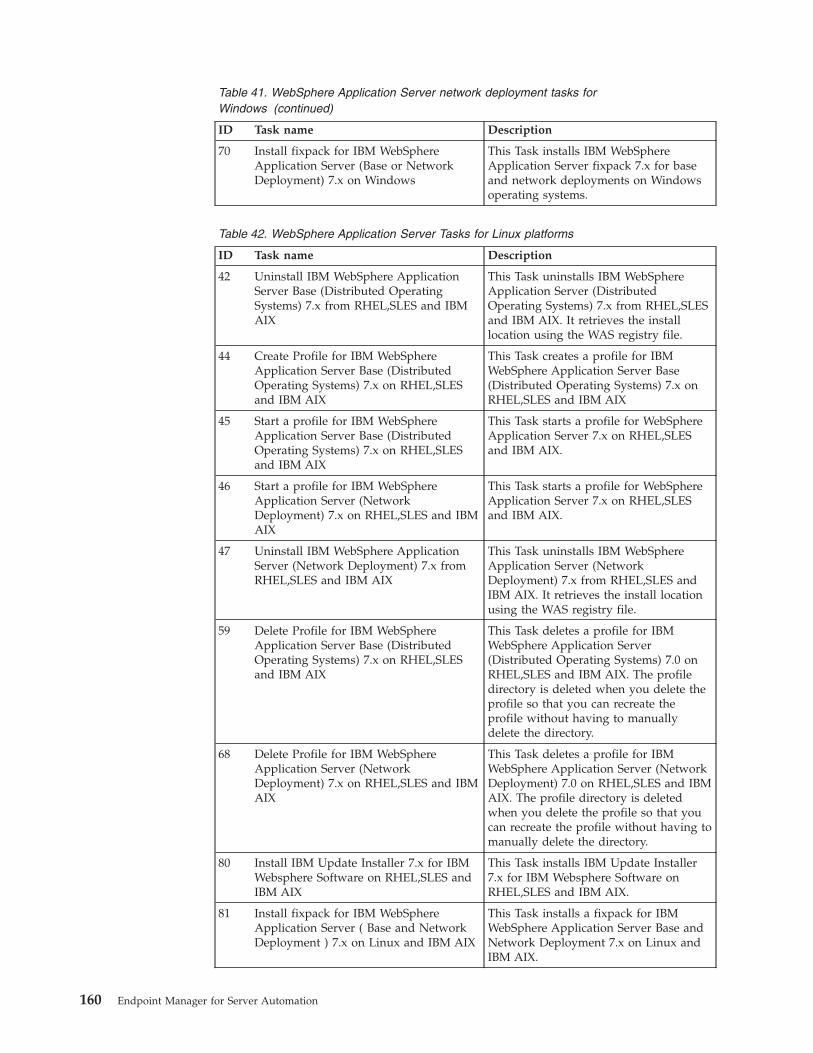
Table 41. WebSphere Application Server network deployment tasks forWindows (continued)
ID Task name Description
70 Install fixpack for IBM WebSphereApplication Server (Base or NetworkDeployment) 7.x on Windows
This Task installs IBM WebSphereApplication Server fixpack 7.x for baseand network deployments on Windowsoperating systems.
Table 42. WebSphere Application Server Tasks for Linux platforms
ID Task name Description
42 Uninstall IBM WebSphere ApplicationServer Base (Distributed OperatingSystems) 7.x from RHEL,SLES and IBMAIX
This Task uninstalls IBM WebSphereApplication Server (DistributedOperating Systems) 7.x from RHEL,SLESand IBM AIX. It retrieves the installlocation using the WAS registry file.
44 Create Profile for IBM WebSphereApplication Server Base (DistributedOperating Systems) 7.x on RHEL,SLESand IBM AIX
This Task creates a profile for IBMWebSphere Application Server Base(Distributed Operating Systems) 7.x onRHEL,SLES and IBM AIX
45 Start a profile for IBM WebSphereApplication Server Base (DistributedOperating Systems) 7.x on RHEL,SLESand IBM AIX
This Task starts a profile for WebSphereApplication Server 7.x on RHEL,SLESand IBM AIX.
46 Start a profile for IBM WebSphereApplication Server (NetworkDeployment) 7.x on RHEL,SLES and IBMAIX
This Task starts a profile for WebSphereApplication Server 7.x on RHEL,SLESand IBM AIX.
47 Uninstall IBM WebSphere ApplicationServer (Network Deployment) 7.x fromRHEL,SLES and IBM AIX
This Task uninstalls IBM WebSphereApplication Server (NetworkDeployment) 7.x from RHEL,SLES andIBM AIX. It retrieves the install locationusing the WAS registry file.
59 Delete Profile for IBM WebSphereApplication Server Base (DistributedOperating Systems) 7.x on RHEL,SLESand IBM AIX
This Task deletes a profile for IBMWebSphere Application Server(Distributed Operating Systems) 7.0 onRHEL,SLES and IBM AIX. The profiledirectory is deleted when you delete theprofile so that you can recreate theprofile without having to manuallydelete the directory.
68 Delete Profile for IBM WebSphereApplication Server (NetworkDeployment) 7.x on RHEL,SLES and IBMAIX
This Task deletes a profile for IBMWebSphere Application Server (NetworkDeployment) 7.0 on RHEL,SLES and IBMAIX. The profile directory is deletedwhen you delete the profile so that youcan recreate the profile without having tomanually delete the directory.
80 Install IBM Update Installer 7.x for IBMWebsphere Software on RHEL,SLES andIBM AIX
This Task installs IBM Update Installer7.x for IBM Websphere Software onRHEL,SLES and IBM AIX.
81 Install fixpack for IBM WebSphereApplication Server ( Base and NetworkDeployment ) 7.x on Linux and IBM AIX
This Task installs a fixpack for IBMWebSphere Application Server Base andNetwork Deployment 7.x on Linux andIBM AIX.
160 Endpoint Manager for Server Automation
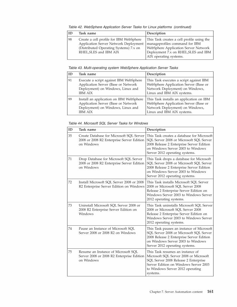
Table 42. WebSphere Application Server Tasks for Linux platforms (continued)
ID Task name Description
98 Create a cell profile for IBM WebSphereApplication Server Network Deployment(Distributed Operating Systems) 7.x onRHEL,SLES and IBM AIX
This Task creates a cell profile using themanageprofiles command for IBMWebSphere Application Server NetworkDeployment 7.x on RHEL,SLES and IBMAIX operating systems.
Table 43. Multi-operating system WebSphere Application Server Tasks
ID Task name Description
91 Execute a script against IBM WebSphereApplication Server (Base or NetworkDeployment) on Windows, Linux andIBM AIX
This Task executes a script against IBMWebSphere Application Server (Base orNetwork Deployment) on Windows,Linux and IBM AIX systems.
99 Install an application on IBM WebSphereApplication Server (Base or NetworkDeployment) on Windows, Linux andIBM AIX
This Task installs an application on IBMWebSphere Application Server (Base orNetwork Deployment) on Windows,Linux and IBM AIX systems.
Table 44. Microsoft SQL Server Tasks for Windows
ID Task name Description
35 Create Database for Microsoft SQL Server2008 or 2008 R2 Enterprise Server Editionon Windows
This Task creates a database for MicrosoftSQL Server 2008 or Microsoft SQL Server2008 Release 2 Enterprise Server Editionon Windows Server 2003 to WindowsServer 2012 operating systems.
71 Drop Database for Microsoft SQL Server2008 or 2008 R2 Enterprise Server Editionon Windows
This Task drops a database for MicrosoftSQL Server 2008 or Microsoft SQL Server2008 Release 2 Enterprise Server Editionon Windows Server 2003 to WindowsServer 2012 operating systems.
72 Install Microsoft SQL Server 2008 or 2008R2 Enterprise Server Edition on Windows
This Task installs Microsoft SQL Server2008 or Microsoft SQL Server 2008Release 2 Enterprise Server Edition onWindows Server 2003 to Windows Server2012 operating systems.
73 Uninstall Microsoft SQL Server 2008 or2008 R2 Enterprise Server Edition onWindows
This Task uninstalls Microsoft SQL Server2008 or Microsoft SQL Server 2008Release 2 Enterprise Server Edition onWindows Server 2003 to Windows Server2012 operating systems.
74 Pause an Instance of Microsoft SQLServer 2008 or 2008 R2 on Windows
This Task pauses an instance of MicrosoftSQL Server 2008 or Microsoft SQL Server2008 Release 2 Enterprise Server Editionon Windows Server 2003 to WindowsServer 2012 operating systems.
75 Resume an Instance of Microsoft SQLServer 2008 or 2008 R2 Enterprise Editionon Windows
This Task resumes an instance ofMicrosoft SQL Server 2008 or MicrosoftSQL Server 2008 Release 2 EnterpriseServer Edition on Windows Server 2003to Windows Server 2012 operatingsystems.
Chapter 7. Server Automation content 161
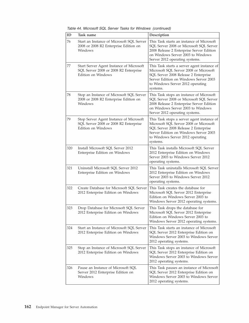
Table 44. Microsoft SQL Server Tasks for Windows (continued)
ID Task name Description
76 Start an Instance of Microsoft SQL Server2008 or 2008 R2 Enterprise Edition onWindows
This Task starts an instance of MicrosoftSQL Server 2008 or Microsoft SQL Server2008 Release 2 Enterprise Server Editionon Windows Server 2003 to WindowsServer 2012 operating systems.
77 Start Server Agent Instance of MicrosoftSQL Server 2008 or 2008 R2 EnterpriseEdition on Windows
This Task starts a server agent instance ofMicrosoft SQL Server 2008 or MicrosoftSQL Server 2008 Release 2 EnterpriseServer Edition on Windows Server 2003to Windows Server 2012 operatingsystems.
78 Stop an Instance of Microsoft SQL Server2008 or 2008 R2 Enterprise Edition onWindows
This Task stops an instance of MicrosoftSQL Server 2008 or Microsoft SQL Server2008 Release 2 Enterprise Server Editionon Windows Server 2003 to WindowsServer 2012 operating systems.
79 Stop Server Agent Instance of MicrosoftSQL Server 2008 or 2008 R2 EnterpriseEdition on Windows
This Task stops a server agent instance ofMicrosoft SQL Server 2008 or MicrosoftSQL Server 2008 Release 2 EnterpriseServer Edition on Windows Server 2003to Windows Server 2012 operatingsystems.
320 Install Microsoft SQL Server 2012Enterprise Edition on Windows
This Task installs Microsoft SQL Server2012 Enterprise Edition on WindowsServer 2003 to Windows Server 2012operating systems.
321 Uninstall Microsoft SQL Server 2012Enterprise Edition on Windows
This Task uninstalls Microsoft SQL Server2012 Enterprise Edition on WindowsServer 2003 to Windows Server 2012operating systems.
322 Create Database for Microsoft SQL Server2012 Enterprise Edition on Windows
This Task creates the database forMicrosoft SQL Server 2012 EnterpriseEdition on Windows Server 2003 toWindows Server 2012 operating systems.
323 Drop Database for Microsoft SQL Server2012 Enterprise Edition on Windows
This Task drops the database forMicrosoft SQL Server 2012 EnterpriseEdition on Windows Server 2003 toWindows Server 2012 operating systems.
324 Start an Instance of Microsoft SQL Server2012 Enterprise Edition on Windows
This Task starts an instance of MicrosoftSQL Server 2012 Enterprise Edition onWindows Server 2003 to Windows Server2012 operating systems.
325 Stop an Instance of Microsoft SQL Server2012 Enterprise Edition on Windows
This Task stops an instance of MicrosoftSQL Server 2012 Enterprise Edition onWindows Server 2003 to Windows Server2012 operating systems.
326 Pause an Instance of Microsoft SQLServer 2012 Enterprise Edition onWindows
This Task pauses an instance of MicrosoftSQL Server 2012 Enterprise Edition onWindows Server 2003 to Windows Server2012 operating systems.
162 Endpoint Manager for Server Automation
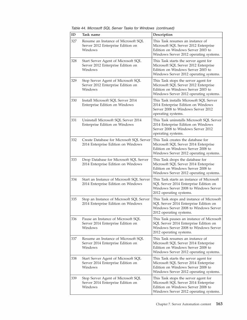
Table 44. Microsoft SQL Server Tasks for Windows (continued)
ID Task name Description
327 Resume an Instance of Microsoft SQLServer 2012 Enterprise Edition onWindows
This Task resumes an instance ofMicrosoft SQL Server 2012 EnterpriseEdition on Windows Server 2003 toWindows Server 2012 operating systems.
328 Start Server Agent of Microsoft SQLServer 2012 Enterprise Edition onWindows
This Task starts the server agent forMicrosoft SQL Server 2012 EnterpriseEdition on Windows Server 2003 toWindows Server 2012 operating systems.
329 Stop Server Agent of Microsoft SQLServer 2012 Enterprise Edition onWindows
This Task stops the server agent forMicrosoft SQL Server 2012 EnterpriseEdition on Windows Server 2003 toWindows Server 2012 operating systems.
330 Install Microsoft SQL Server 2014Enterprise Edition on Windows
This Task installs Microsoft SQL Server2014 Enterprise Edition on WindowsServer 2008 to Windows Server 2012operating systems.
331 Uninstall Microsoft SQL Server 2014Enterprise Edition on Windows
This Task uninstalls Microsoft SQL Server2014 Enterprise Edition on WindowsServer 2008 to Windows Server 2012operating systems.
332 Create Database for Microsoft SQL Server2014 Enterprise Edition on Windows
This Task creates the database forMicrosoft SQL Server 2014 EnterpriseEdition on Windows Server 2008 toWindows Server 2012 operating systems.
333 Drop Database for Microsoft SQL Server2014 Enterprise Edition on Windows
This Task drops the database forMicrosoft SQL Server 2014 EnterpriseEdition on Windows Server 2008 toWindows Server 2012 operating systems.
334 Start an Instance of Microsoft SQL Server2014 Enterprise Edition on Windows
This Task starts an instance of MicrosoftSQL Server 2014 Enterprise Edition onWindows Server 2008 to Windows Server2012 operating systems.
335 Stop an Instance of Microsoft SQL Server2014 Enterprise Edition on Windows
This Task stops and instance of MicrosoftSQL Server 2014 Enterprise Edition onWindows Server 2008 to Windows Server2012 operating systems.
336 Pause an Instance of Microsoft SQLServer 2014 Enterprise Edition onWindows
This Task pauses an instance of MicrosoftSQL Server 2014 Enterprise Edition onWindows Server 2008 to Windows Server2012 operating systems.
337 Resume an Instance of Microsoft SQLServer 2014 Enterprise Edition onWindows
This Task resumes an instance ofMicrosoft SQL Server 2014 EnterpriseEdition on Windows Server 2008 toWindows Server 2012 operating systems.
338 Start Server Agent of Microsoft SQLServer 2014 Enterprise Edition onWindows
This Task starts the server agent forMicrosoft SQL Server 2014 EnterpriseEdition on Windows Server 2008 toWindows Server 2012 operating systems.
339 Stop Server Agent of Microsoft SQLServer 2014 Enterprise Edition onWindows
This Task stops the server agent forMicrosoft SQL Server 2014 EnterpriseEdition on Windows Server 2008 toWindows Server 2012 operating systems.
Chapter 7. Server Automation content 163
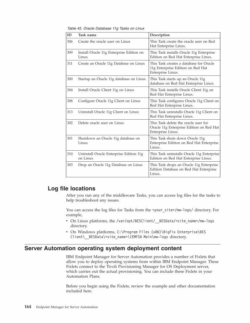
Table 45. Oracle Database 11g Tasks on Linux
ID Task name Description
306 Create the oracle user on Linux This Task create the oracle user on RedHat Enterprise Linux.
309 Install Oracle 11g Enterprise Edition onLinux
This Task installs Oracle 11g EnterpriseEdition on Red Hat Enterprise Linux.
311 Create an Oracle 11g Database on Linux This Task creates a database for Oracle11g Enterprise Edition on Red HatEnterprise Linux.
300 Startup an Oracle 11g database on Linux This Task starts up an Oracle 11gdatabase on Red Hat Enterprise Linux.
304 Install Oracle Client 11g on Linux This Task installs Oracle Client 11g onRed Hat Enterprise Linux.
308 Configure Oracle 11g Client on Linux This Task configures Oracle 11g Client onRed Hat Enterprise Linux.
313 Uninstall Oracle 11g Client on Linux This Task uninstalls Oracle 11g Client onRed Hat Enterprise Linux.
302 Delete oracle user on Linux This Task delete the oracle user forOracle 11g Enterprise Edition on Red HatEnterprise Linux.
301 Shutdown an Oracle 11g database onLinux
This Task shuts down Oracle 11gEnterprise Edition on Red Hat EnterpriseLinux.
310 Uninstall Oracle Enterprise Edition 11gon Linux
This Task uninstalls Oracle 11g EnterpriseEdition on Red Hat Enterprise Linux.
303 Drop an Oracle 11g Database on Linux This Task drops an Oracle 11g EnterpriseEdition Database on Red Hat EnterpriseLinux.
Log file locationsAfter you run any of the middleware Tasks, you can access log files for the tasks tohelp troubleshoot any issues.
You can access the log files for Tasks from the <your_site>/mw-logs/ directory. Forexample,v On Linux platforms, the /var/opt/BESClient/__BESData/<site_name>/mw-logs
directory.v On Windows platforms, C:\Program Files (x86)\BigFix Enterprise\BES
Client\__BESData\<site_name>\IEMFSA Main\mw-logs directory.
Server Automation operating system deployment contentIBM Endpoint Manager for Server Automation provides a number of Fixlets thatallow you to deploy operating systems from within IBM Endpoint Manager. TheseFixlets connect to the Tivoli Provisioning Manager for OS Deployment server,which carries out the actual provisioning. You can include these Fixlets in yourAutomation Plans.
Before you begin using the Fixlets, review the example and other documentationincluded here.
164 Endpoint Manager for Server Automation
This version of Server Automation supports operating system deployment forWindows server operating systems and Linux operating systems.
Example: end-to-end provisioningIn this example we are going to look at how you can use the IBM EndpointManager Operating System deployment and Server Automation applications tocomplete an end-to-end server deployment. This example shows a process startingwith the deployment of an operating system profile on a newly created computerthrough to the point where the newly created computer is up and running as aweb server. The entire process is fully automated end-to-end using an AutomationPlan.
To begin the process, we first create a simple two step Automation Plan, asfollows:v For step 1, we want to provision a new computer with an operating system and
a software image. We can do this by adding the Deploy operating system toone or more registered computers Fixlet as the first step in our AutomationPlan. The operating system profile contains a version of the Red Hat EnterpriseLinux operating system. This version of Red Hat Enterprise Linux contains anApache HTTP system.
v Then we add a second step to our Automation Plan. This step is a baseline withsix components that we have created for this purpose. Step 2 will apply a patchto the Apache HTTP system and then start the Apache web server so that whenthe Automation Plan has completed, we have provisioned a new computer andit will be up and running as a web server. The baseline contains components forthe following:– Change the CPU usage– Stop the Apache server– Apply a patch– Restart the computer– Start Apache– Set the CPU usage back to normal level
To run the Automation Plan we click Take Action:1. For step 1, we need to target the Bare Metal Server that contains the operating
system profile that we want to deploy for the new computer. We also need tospecify the required parameters for step 1 in our Automation Plan. Theserequired parameters are:v MAC address of the new computer.v The new computer's computer name. We need to note this as we need to
provide it when specifying the target for step 2.v We select the Bare Metal Profile that we want to deploy on the new
computer. This is the operating system profile that we want to deploy on thenew computer.
This completes the first step in the Automation Plan, and by the time this stephas completed, the new computer will be provisioned with an operating systemand an Apache web server.
2. For step 2 in the Automation Plan, which is to apply a baseline to this newcomputer created in step 1, we must specify the target computer. Because thetarget computer does not yet exist and we cannot select it in the system, we
Chapter 7. Server Automation content 165
need to target it by its computer name that we entered in step 1. We enter thecomputer name that we specified for the new computer in step 1 of theAutomation Plan.
3. The Automation Plan is now ready to go so we click OK. The Automation Planis then executed and we can track its progress.
After the Automation Plan has completed, a new computer has been created and isup and running as a web server.
How it worksYou must have Tivoli Provisioning Manager for OS Deployment set up and youneed to complete some configuration to connect Tivoli Provisioning Manager forOS Deployment to your IBM Endpoint Manager system.
Requirements
You need to configure your IBM Endpoint Manager system to work with the TivoliProvisioning Manager for OS Deployment application. For information about howto configure this, see OS Deployment User's Guide Setup.
How it works
This version of Server Automation supports operating system deployment forWindows server operating systems and Linux operating systems.
You create and manage your .RAD bare metal profiles, also known as operatingsystem profiles, in Tivoli Provisioning Manager for OS Deployment. Note that only.RAD format profiles are supported. You can then use the OS Deployment andBare Metal Imaging application in the Systems Lifecycle domain in IBM EndpointManager to import those profiles into your IBM Endpoint Manager system. Afteryou have imported these bare metal profiles into the IBM Endpoint Managersystem, the profiles become available for selection in the Server Automation Fixlets.For more information about how to use the OS Deployment and Bare MetalImaging application, see OS Deployment User's Guide.
Fixlets for operating system deploymentServer Automation provides a number of Fixlets that you can use for operatingsystem deployment provisioning. You can include these in your Automation Plans.Including these Fixlets in your Automation Plans allows you to completeend-to-end provisioning, where you can add a step to your Automation Plan toperform the bare metal provisioning, and then other steps to deploy software andpatch the computers.
Server Automation includes the Fixlets described in the following table.
166 Endpoint Manager for Server Automation
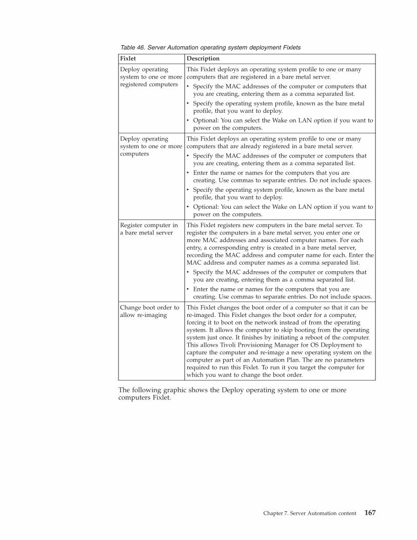
Table 46. Server Automation operating system deployment Fixlets
Fixlet Description
Deploy operatingsystem to one or moreregistered computers
This Fixlet deploys an operating system profile to one or manycomputers that are registered in a bare metal server.
v Specify the MAC addresses of the computer or computers thatyou are creating, entering them as a comma separated list.
v Specify the operating system profile, known as the bare metalprofile, that you want to deploy.
v Optional: You can select the Wake on LAN option if you want topower on the computers.
Deploy operatingsystem to one or morecomputers
This Fixlet deploys an operating system profile to one or manycomputers that are already registered in a bare metal server.
v Specify the MAC addresses of the computer or computers thatyou are creating, entering them as a comma separated list.
v Enter the name or names for the computers that you arecreating. Use commas to separate entries. Do not include spaces.
v Specify the operating system profile, known as the bare metalprofile, that you want to deploy.
v Optional: You can select the Wake on LAN option if you want topower on the computers.
Register computer ina bare metal server
This Fixlet registers new computers in the bare metal server. Toregister the computers in a bare metal server, you enter one ormore MAC addresses and associated computer names. For eachentry, a corresponding entry is created in a bare metal server,recording the MAC address and computer name for each. Enter theMAC address and computer names as a comma separated list.
v Specify the MAC addresses of the computer or computers thatyou are creating, entering them as a comma separated list.
v Enter the name or names for the computers that you arecreating. Use commas to separate entries. Do not include spaces.
Change boot order toallow re-imaging
This Fixlet changes the boot order of a computer so that it can bere-imaged. This Fixlet changes the boot order for a computer,forcing it to boot on the network instead of from the operatingsystem. It allows the computer to skip booting from the operatingsystem just once. It finishes by initiating a reboot of the computer.This allows Tivoli Provisioning Manager for OS Deployment tocapture the computer and re-image a new operating system on thecomputer as part of an Automation Plan. The are no parametersrequired to run this Fixlet. To run it you target the computer forwhich you want to change the boot order.
The following graphic shows the Deploy operating system to one or morecomputers Fixlet.
Chapter 7. Server Automation content 167
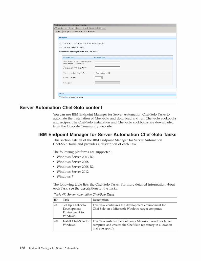
Server Automation Chef-Solo contentYou can use IBM Endpoint Manager for Server Automation Chef-Solo Tasks toautomate the installation of Chef-Solo and download and run Chef-Solo cookbooksand recipes. The Chef-Solo installation and Chef-Solo cookbooks are downloadedfrom the Opscode Community web site.
IBM Endpoint Manager for Server Automation Chef-Solo TasksThis section lists all of the IBM Endpoint Manager for Server AutomationChef-Solo Tasks and provides a description of each Task.
The following platforms are supported:v Windows Server 2003 R2v Windows Server 2008v Windows Server 2008 R2v Windows Server 2012v Windows 7
The following table lists the Chef-Solo Tasks. For more detailed information abouteach Task, see the descriptions in the Tasks.
Table 47. Server Automation Chef-Solo Tasks
ID Task Description
200 Set Up Chef-SoloDevelopmentEnvironment forWindows
This Task configures the development environment forChef-Solo on a Microsoft Windows target computer.
201 Install Chef-Solo forWindows
This Task installs Chef-Solo on a Microsoft Windows targetcomputer and creates the Chef-Solo repository in a locationthat you specify.
168 Endpoint Manager for Server Automation
Table 47. Server Automation Chef-Solo Tasks (continued)
ID Task Description
202 Download Chef-SoloCookbook fromOpscode
This Task downloads a Cookbook from the OpscodeCommunity site and adds it to the Chef-Solo repository onthe target computer.
203 Download Chef-SoloCookbook from url
This Task downloads a Cookbook from a URL and adds it tothe Chef-Solo repository on the target computer.
204 Run a downloadedChef-Solo Cookbook
This Task runs a Chef-Solo Cookbook that has previouslybeen downloaded to a Microsoft Windows target computer.
205 Run a downloadedChef-Solo Recipe
This Task runs a Chef-Solo Recipe that has previously beendownloaded to a Microsoft Windows target computer.
Server Automation RXAYou can use Server Automation content to install RXA on a system on which theIBM® Endpoint Manager agent is installed. RXA allows you to use that system asan intermediary to execute IBM® Endpoint Manager functionality on a differentsystem, one that does not have the IBM Endpoint Manager agent installed, forexample, Linux embedded targets.
Installing RXAYou can install RXA on IBM Endpoint Manager versions 9.0 and 9.1.
About this task
Ensure that the endpoints that you are planning to run RXA actions against arecapable of receiving RXA commands. Make sure that these endpoints are notsecured so that no communication can be established. For example, the sshddaemon in the case of a Unix systems should be running and accessible. For thecurrent release, you must install RXA on a Windows system.
Complete the following steps to install RXA on a Microsoft® Windows® system:
Procedure1. Open the IBM® Endpoint Manager console.2. Search for Fixlet 120 Install TEM RXA Tool v8.2.1.3. Target the Microsoft® Windows® system on which you want to install RXA.4. Click OK to run the installation.
Results
RXA is installed. After the installation is completed, an Applications folder iscreated in the Bes Client\Applications and you can review the contents of theinstallation in the Bes Client\Applications\IEM_RXA_8.2. To uninstall RXA, deletethe Allocations folder.
Chapter 7. Server Automation content 169

170 Endpoint Manager for Server Automation
Chapter 8. Notices
IBM may not offer the products, services, or features discussed in this document inother countries. Consult your local IBM representative for information on theproducts and services currently available in your area. Any reference to an IBMproduct, program, or service is not intended to state or imply that only that IBMproduct, program, or service may be used. Any functionally equivalent product,program, or service that does not infringe any IBM intellectual property right maybe used instead. However, it is the user's responsibility to evaluate and verify theoperation of any non-IBM product, program, or service.
IBM may have patents or pending patent applications covering subject matterdescribed in this
document. The furnishing of this document does not grant you any license to thesepatents. You can send license inquiries, in writing, to:
IBM Director of Licensing
IBM Corporation
North Castle Drive
Armonk, NY 10504-1785
U.S.A.
For license inquiries regarding double-byte (DBCS) information, contact the IBMIntellectual Property Department in your country or send inquiries, in writing, to:
Intellectual Property Licensing
Legal and Intellectual Property Law
IBM Japan Ltd.
1623-14, Shimotsuruma, Yamato-shi
Kanagawa 242-8502 Japan
The following paragraph does not apply to the United Kingdom or any othercountry where such
provisions are inconsistent with local law: INTERNATIONAL BUSINESSMACHINES CORPORATION PROVIDES THIS PUBLICATION "AS IS" WITHOUTWARRANTY OF ANY KIND, EITHER EXPRESS OR IMPLIED, INCLUDING, BUTNOT LIMITED TO, THE IMPLIED WARRANTIES OF NON-INFRINGEMENT,MERCHANTABILITY OR FITNESS FOR A PARTICULAR PURPOSE. Some statesdo not allow disclaimer of express or implied warranties in certain transactions,therefore, this statement may not apply to you.
This information could include technical inaccuracies or typographical errors.Changes are periodically made to the information herein; these changes will be
171
incorporated in new editions of the publication. IBM may make improvementsand/or changes in the product(s) and/or the program(s) described in thispublication at any time without notice.
Any references in this information to non-IBM Web sites are provided forconvenience only and do not in any manner serve as an endorsement of those Websites. The materials at those Web sites are not part of the materials for this IBMproduct and use of those Web sites is at your own risk.
IBM may use or distribute any of the information you supply in any way itbelieves appropriate without incurring any obligation to you
Licensees of this program who wish to have information about it for the purposeof enabling: (i) the exchange of information between independently createdprograms and other programs (including this one) and (ii) the mutual use of theinformation which has been exchanged, should contact:
IBM Corporation
2Z4A/101
11400 Burnet Road
Austin, TX 78758 U.S.A.
Such information may be available, subject to appropriate terms and conditions,including in some cases payment of a fee.
The licensed program described in this document and all licensed materialavailable for it are provided by IBM under terms of the IBM Customer Agreement,IBM International Program License Agreement or any equivalent agreementbetween us.
Information concerning non-IBM products was obtained from the suppliers ofthose products, their
published announcements or other publicly available sources. IBM has not testedthose products and cannot confirm the accuracy of performance, compatibility orany other claims related to non-IBM products. Questions on the capabilities ofnon-IBM products should be addressed to the suppliers of those products.
COPYRIGHT LICENSE:
This information contains sample application programs in source language, whichillustrate programming techniques on various operating platforms. You may copy,modify, and distribute these sample programs in any form without payment toIBM, for the purposes of developing, using, marketing or distributing applicationprograms conforming to the application programming interface for the operatingplatform for which the sample programs are written. These examples have notbeen thoroughly tested under all conditions. IBM, therefore, cannot guarantee orimply reliability, serviceability, or function of these programs. The sampleprograms are provided "AS IS", without warranty of any kind. IBM shall not beliable for any damages arising out of your use of the sample programs.
TRADEMARKS:
172 Endpoint Manager for Server Automation

IBM, the IBM logo, and ibm.com are trademarks or registered trademarks ofInternational Business Machines Corporation in the United States, other countries,or both.
If these and other IBM trademarked terms are marked on their first occurrence inthis information with a trademark symbol ( or ™), these symbols indicate U.S.registered or common law trademarks owned by IBM at the time this informationwas published. Such trademarks may also
be registered or common law trademarks in other countries. A current list of IBMtrademarks is available on the Web at "Copyright and trademark information" athttp://www.ibm.com/legal/copytrade.shtml.
Adobe, the Adobe logo, PostScript, and the PostScript logo are either registeredtrademarks or trademarks of Adobe Systems Incorporated in the United States,and/or other countries.
Java and all Java-based trademarks and logos are trademarks or registeredtrademarks of Oracle and/or its affiliates.
Microsoft, Windows, Windows NT, and the Windows logo are trademarks ofMicrosoft Corporation in the United States, other countries, or both.
Linux is a registered trademark of Linus Torvalds in the United States, othercountries, or both.
UNIX is a registered trademark of The Open Group in the United States and othercountries.
Other company, product, and service names may be trademarks or service marksof others.
Chapter 8. Notices 173

174 Endpoint Manager for Server Automation

Index
Aaction state mapping 41AIX NIM
Create Mksysb 86Create NIM client 85NIM master server 87Setup Tasks 81Uninstall NIM Client 87
AIX NIM plug-inConfigure 82Deploy 81Install 81Re-configure 82Remove 85Uninstall 85Upgrade 84
Automation Plan 1, 19adding steps 21copying 39creating 21data 20deleting 40editing 36examples 1exporting 48failure step 34overview 19processing 34running 41stopping 47
Automation Plan actionsstopping 34, 47viewing 45
Automation Plan Editorcreating an Automation Plan 21
Automation Plan Engineautomatic shutdown 35configuration files
config.xml 12log4j.prop 12PlanEngine.xml 35
configuration properties 12error conditions 35installation
overview 9prerequisites 10process 9troubleshooting Tasks 12
installation Task 11installing 11uninstallation
troubleshooting 17uninstallation Task 16uninstalling 16
Automation Plan features 19Automation Plan Sample
Build LPAR with two disks 114Build PowerVM LPAR 113
Automation Plan step actionsdeleting 121stopping 47
DData center configuration 7
Ffailure step
parameters 41targets 41
IIBM Endpoint Manager
architecture 120IBM Endpoint Manager console
user credentials 35IBM Endpoint Manager Platform
user credentials 10IBM Endpoint Manager server plugin
service 11, 35IBM Endpoint Manager Web Reports
service 10user credentials 10, 35
ISO imagesrefreshing 69
LLogical Partition
Activate LPAR 108Activate Multiple LPARs 109Add disk 105Create a profile 99Create LPAR 93Create New Disk 105Deactivate 110Deactivate Multiple LPARs 111Delete LPAR 98Delete Storage Disk 98Memory
Modify 103Modify LPAR 103Netboot an LPAR 111Power off 110Power On LPAR 108Processing Settings
Modify 103Processors
Modify 103Storage NPIV
Logical Volume 105Physical Volume 105vSCSI 105
MManage Software Distribution
dashboard 152management extender
configuring 52
management extender (continued)installing 17, 51uninstalling 54upgrading 53
Management Extender for PowerVMConfigure 89Remove 92Upgrade plug-in 91
NNIM master server 85NIM Operations 87NIM server 85
Netboot on a NIM server 111
PPowerVM 93PowerVM plug-in
Deploy 88Install 88Management extender plug-in 88
ProfileCreate a profile 99Modify Profile 103
SServer Automation
architecture 5Chef-Solo
Tasks 168configuration 119examples 1key features 6latency 120middleware
log files 164overview 152prerequisites 152Tasks 154
open actionsmaximum number allowed 121
overview 1performance
optimum 121site
acquiring 8system performance 119use cases 1
Server Automation domainupgrading 18
Server Automation PlanWebsphere Server Sample 116
Server Automation Plan SampleLPAR with DB2 115
Software Distribution site 152step 1, 19
actions 19
175

step (continued)endpoints 41parameters 41
changing default values 49targets 41
step actionsviewing 45
StorageMulti path input/output 93NPIV 93vSCSI
Logical Volume 93Physical Volume 93
TTake Automation Plan Action 41
Vvirtual machine
cloning to template 72
virtual machine (continued)converting to template 70creating 57creating a snapshot 74deleting 60go to a snapshot 76modifying 58parameters 57, 58
validation 58powering off (hard) 77powering off (soft) 78powering on 77removing a snapshot 75removing all snapshots 75renaming a snapshot 74restarting (hard) 79restarting (soft) 79reverting a snapshot 76suspending (hard) 80suspending (soft) 80
virtual serverhost attributes 55overview 55
virtual server (continued)virtual machine attributes 55
virtual serversintroduction 51
virtualizationenvironment
maintenance tasks 51setup tasks 51
VMware datastoreISO images 69
VMware Tools 62
WWindows administrator password
configuring 53Windows virtual machine
create from template 62creating from template
prerequisite 53parameters
validation 62
176 Endpoint Manager for Server Automation