Enclosure and process_cooling
98
Enclosure and process cooling The Rittal technology library 2013 2
Transcript of Enclosure and process_cooling
Enclosure and process
cooling
The Rittal technology library20132
Enclosure and
process cooling
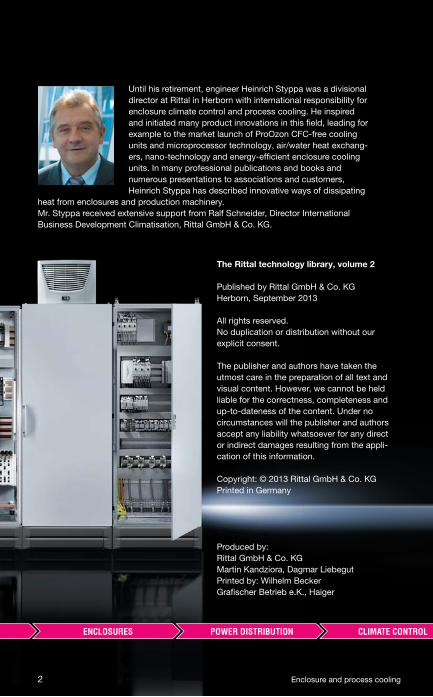
Until his retirement, engineer Heinrich Styppa was a divisional
director at Rittal in Herborn with international responsibility for
enclosure climate control and process cooling. He inspired
and initiated many product innovations in this field, leading for
example to the market launch of ProOzon CFC-free cooling
units and microprocessor technology, air/water heat exchang-
ers, nano-technology and energy-efficient enclosure cooling
units. In many professional publications and books and
numerous presentations to associations and customers,
Heinrich Styppa has described innovative ways of dissipating
heat from enclosures and production machinery.
Mr. Styppa received extensive support from Ralf Schneider, Director International
Business Development Climatisation, Rittal GmbH & Co. KG.
The Rittal technology library, volume 2
Published by Rittal GmbH & Co. KG
Herborn, September 2013
All rights reserved.
No duplication or distribution without our
explicit consent.
The publisher and authors have taken the
utmost care in the preparation of all text and
visual content. However, we cannot be held
liable for the correctness, completeness and
up-to-dateness of the content. Under no
circumstances will the publisher and authors
accept any liability whatsoever for any direct
or indirect damages resulting from the appli-
cation of this information.
Copyright: © 2013 Rittal GmbH & Co. KG
Printed in Germany
Produced by:
Rittal GmbH & Co. KG
Martin Kandziora, Dagmar Liebegut
Printed by: Wilhelm Becker
Grafischer Betrieb e.K., Haiger
2 Enclosure and process cooling
Preface
In view of escalating global environmental problems and rising energy
prices, energy effi ciency is a key issue for industrial production processes
looking ahead to the future.
The advanced technology of German machine tool manufacturers has an
added advantage – namely energy effi ciency.
The product benefi ts and features that distinguish them from international
competitors include not only their precision, productivity, quality and
safety, but also their low energy consumption. The European Union has
already responded by including machine tools in the list of energy-using
products under the EUP directive.
Due to the increasingly powerful technology used in production processes,
heat loss in enclosures has also increased rapidly.
With its highly effi cient climate control solutions, in which energy-effi ciency
is treated as a priority, Rittal has taken this trend on board and devel-
oped climate control components and cooling systems with a continuous
increase in effi ciency of more than 40% compared with the old systems.
Today – and not without good reason – Rittal is an international market
leader and above all a technology leader in the fi eld of climate control sys-
tems for enclosures, machines, server racks and data centres.
This book describes the possibilities of a future-oriented, energy-effi cient
cooling system for enclosures and machinery.
Heinrich Styppa
Enclosure and process cooling 3
4 Enclosure and process cooling
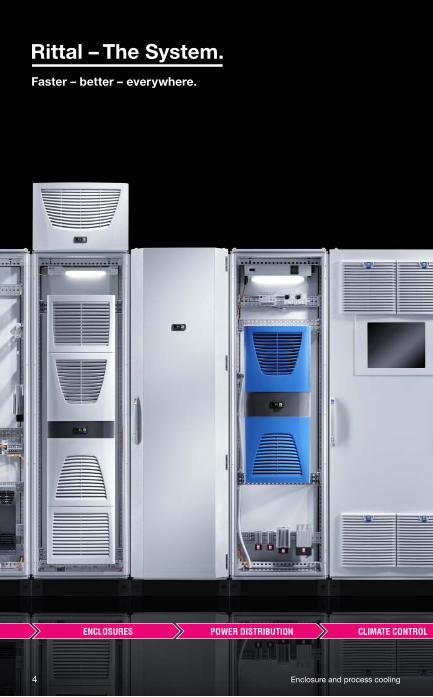
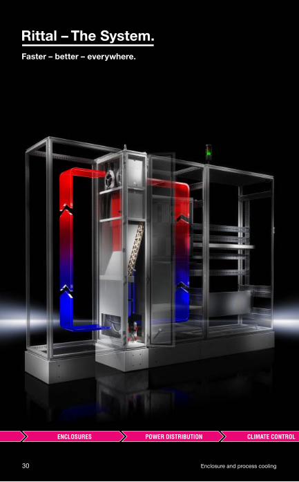
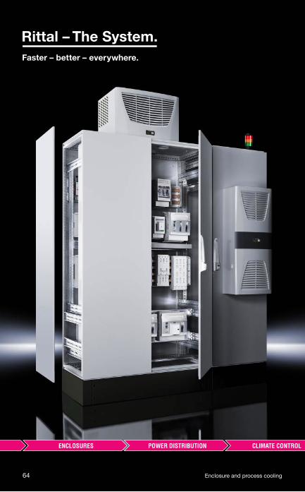
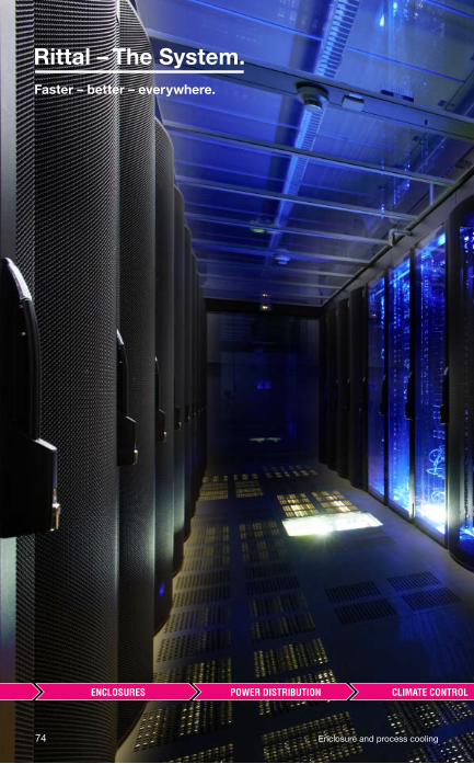
The whole is more than the sum of its parts
The same is true of “Rittal – The System.” With this in mind,
we have bundled our innovative enclosure, power distribution,
climate control and IT infrastructure products together into a single
system platform. Complemented by our extensive range of software
tools and global service, we create unique added value for all
industrial applications: Production plant, test equipment, facil-
ity management and data centres. In accordance with our simple
principle, “Faster – better – everywhere”, we are able to combine
innovative products and effi cient service to optimum eff ect.
Faster – with our “Rittal – The System.” range of modular solutions,
which guarantees fast planning, assembly, conversion and commis-
sioning with its system compatibility.
Better – by being quick to translate market trends into products.
In this way, our innovative strength helps you to secure competitive
advantages.
Everywhere – thanks to global networking across 150 locations.
Rittal has over 60 subsidiaries, more than 250 service partners
and over 1,000 service engineers worldwide. For more than
50 years, we have been on hand to off er advice, assistance and
product solutions.
Enclosure and process cooling 5
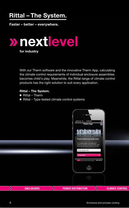
nextlevelfor industry
With our Therm software and the innovative Therm App, calculating
the climate control requirements of individual enclosure assemblies
becomes child's play. Meanwhile, the Rittal range of climate control
products has the right solution to suit every application.
Rittal – The System.
◾ Rittal – Therm
◾ Rittal – Type-tested climate control systems
6 Enclosure and process cooling
Enclosure and process cooling 7
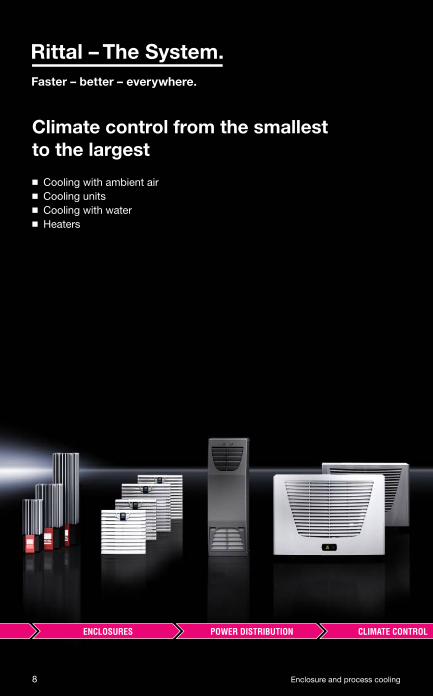
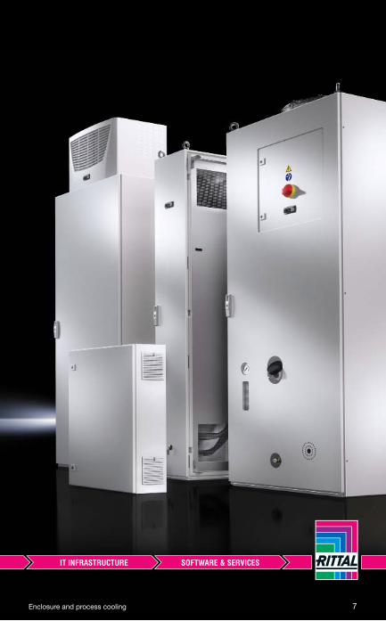
Climate control from the smallest
to the largest
◾ Cooling with ambient air
◾ Cooling units
◾ Cooling with water
◾ Heaters
8 Enclosure and process cooling
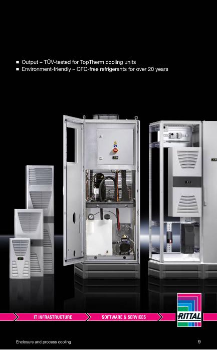
◾ Output – TÜV-tested for TopTherm cooling units
◾ Environment-friendly – CFC-free refrigerants for over 20 years
Enclosure and process cooling 9
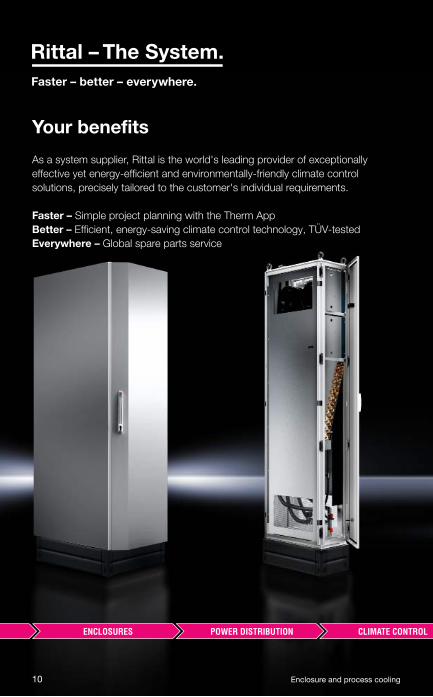
Your benefi ts
As a system supplier, Rittal is the world's leading provider of exceptionally
effective yet energy-efficient and environmentally-friendly climate control
solutions, precisely tailored to the customer's individual requirements.
Faster – Simple project planning with the Therm App
Better – Efficient, energy-saving climate control technology, TÜV-tested
Everywhere – Global spare parts service
10 Enclosure and process cooling
Enclosure and process cooling 11
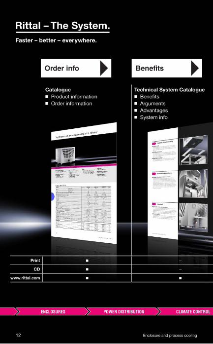
Order info Benefits
Catalogue
◾ Product information
◾ Order information
Technical System Catalogue
◾ Benefi ts
◾ Arguments
◾ Advantages
◾ System info
Print ◾ –
CD ◾ –
www.rittal.com ◾ ◾
12 Enclosure and process cooling
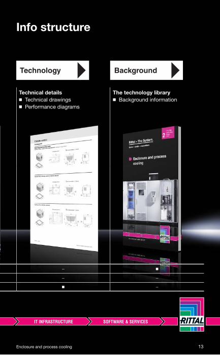
Info structure
Technology Background
Technical details
◾ Technical drawings
◾ Performance diagrams
The technology library
◾ Background information
– ◾
– –
◾ –
Enclosure and process cooling 13
14 Enclosure and process cooling
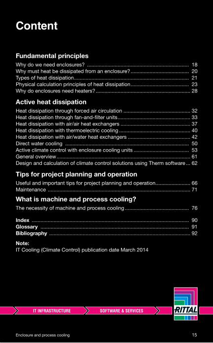
Fundamental principles
Why do we need enclosures? ...................................................................... 18
Why must heat be dissipated from an enclosure? ........................................ 20
Types of heat dissipation ............................................................................... 21
Physical calculation principles of heat dissipation ........................................ 23
Why do enclosures need heaters? ................................................................. 28
Active heat dissipation
Heat dissipation through forced air circulation .............................................. 32
Heat dissipation through fan-and-fi lter units .................................................. 33
Heat dissipation with air/air heat exchangers ................................................ 37
Heat dissipation with thermoelectric cooling ................................................. 40
Heat dissipation with air/water heat exchangers ........................................... 42
Direct water cooling ..................................................................................... 50
Active climate control with enclosure cooling units ...................................... 53
General overview ............................................................................................ 61
Design and calculation of climate control solutions using Therm software ... 62
Tips for project planning and operation
Useful and important tips for project planning and operation........................ 66
Maintenance .................................................................................................. 71
What is machine and process cooling?
The necessity of machine and process cooling ............................................ 76
Index ............................................................................................................ 90
Glossary ...................................................................................................... 91
Bibliography ................................................................................................. 92
Note:
IT Cooling (Climate Control) publication date March 2014
Content
Enclosure and process cooling 15
16 Enclosure and process cooling

Enclosure and process cooling 17
Fundamental principles
Why do we need enclosures? ............................................ 18
Why must heat be dissipated from an enclosure? ........... 20
Types of heat dissipation ................................................... 21◾ Enclosure surface cooling ......................................................................... 21
◾ Air fl ow cooling .......................................................................................... 22
Physical calculation principles of heat dissipation ......... 23
Why do enclosures need heaters? ..................................... 28
18 Enclosure and process cooling
Fundamental principles
■ Why do we need enclosures?
The main function of an enclosure is to protect electronic components and devices from aggressive media such as humidity, water, oil-contaminated ambient air, corrosive vapours and also dust in the ambient air.
If these are not prevented, electronic components will inevitably fail, eventu-ally leading to the shut-down of entire production systems. The failure of a production system generates costs that can add up to huge sums.
It is therefore the job of a housing or enclosure to provide lasting protection of sensitive and expensive electronic and microelectronic components.
There are diff erent protection catego-ries relating to the ambient conditions, which depend on the installation loca-tion of the enclosure.
The protection categories are defi ned on the basis of IP codes or NEMA type ratings.
The abbreviation IP stands for Ingress Protection. The protection category is defi ned by means of codes consist-ing of two letters, which always remain the same, and two numerals.
The relevant standard for enclosure construction or control system design is IEC 60 529 (VDE 0470-1).
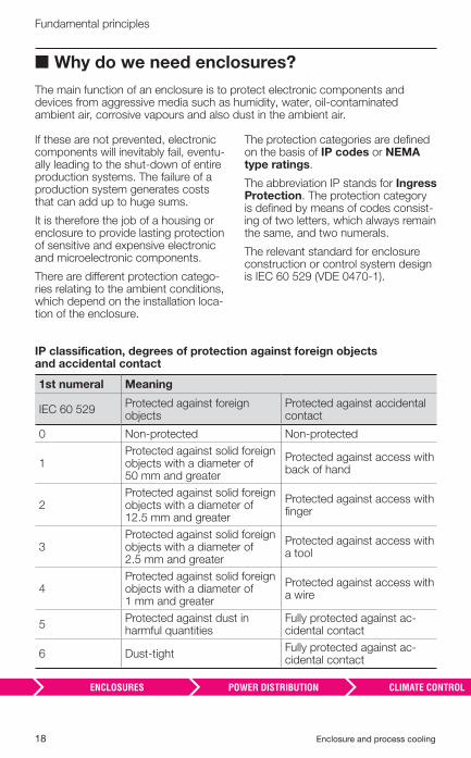
IP classification, degrees of protection against foreign objects and accidental contact
1st numeral Meaning
IEC 60 529Protected against foreign objects
Protected against accidental contact
0 Non-protected Non-protected
1Protected against solid foreign objects with a diameter of 50 mm and greater
Protected against access with back of hand
2Protected against solid foreign objects with a diameter of 12.5 mm and greater
Protected against access with fi nger
3Protected against solid foreign objects with a diameter of 2.5 mm and greater
Protected against access with a tool
4Protected against solid foreign objects with a diameter of 1 mm and greater
Protected against access with a wire
5Protected against dust in harmful quantities
Fully protected against ac-cidental contact
6 Dust-tightFully protected against ac-cidental contact

Enclosure and process cooling 19
Fundamental principles
IP classification, degrees of protection against water
2nd numeral Meaning
IEC 60 529 Protection from water
0 Non-protected
1 Protected against vertically falling water drops
2Protected against vertically falling water drops when the enclosure is tilted up to 15°
3Protected against water sprayed at an angle of up to 60º to the vertical
4 Protected against water splashed from any direction
5 Protected against water jets sprayed from any direction
6 Protected against powerful water jets
7 Protected against the eff ects of temporary immersion
8 Protected against the eff ects of continuous immersion
NEMA stands for the National Elec-trical Manufacturers Association.
High levels of protection are required nowadays for modern enclosures, therefore the enclosures must be relatively impermeable. This means that infl uences from the environment
cannot penetrate the enclosure, but also that the heat loss caused by the electronic components cannot be dissipated to the outside.
NEMA classification
Type ratings
1 Enclosures constructed for indoor use protected against falling dirt
4Enclosures constructed for indoor or outdoor use protected against windblown dust and rain, splashing water and sprayed water; also protected against external formation of ice on the enclosure
4XEnclosures constructed for indoor or outdoor use protected against windblown dust and rain, splashing water, sprayed water and corrosion; also protected against external formation of ice on the enclosure
12Enclosures constructed for indoor use protected against falling dirt, circulating dust and dripping, non-corrosive liquids
20 Enclosure and process cooling
Fundamental principles
■ Why does heat have to be dissipated from an enclosure?
In addition to negative external infl uences such as oil-contaminated and humid ambient air and dust, heat is the number one enemy of today's high-perfor-mance electronic and microelectronic components in enclosures.
Relative to each individual component, the heat loss of electronic compo-nents has diminished signifi cantly in recent years. At the same time, however, the packing density inside enclosures has increased dramatically, resulting in a 50 – 60% increase in heat loss in the enclosures.
With the advent of microelectron-ics and new electronic components, the requirements for professional enclosure construction have changed and thus also the requirements for heat dissipation from enclosures and electronic housings.
Modern enclosure climate control systems must take these new circum-stances into account, off ering the best
technical solution whilst guaranteeing optimum energy effi ciency.
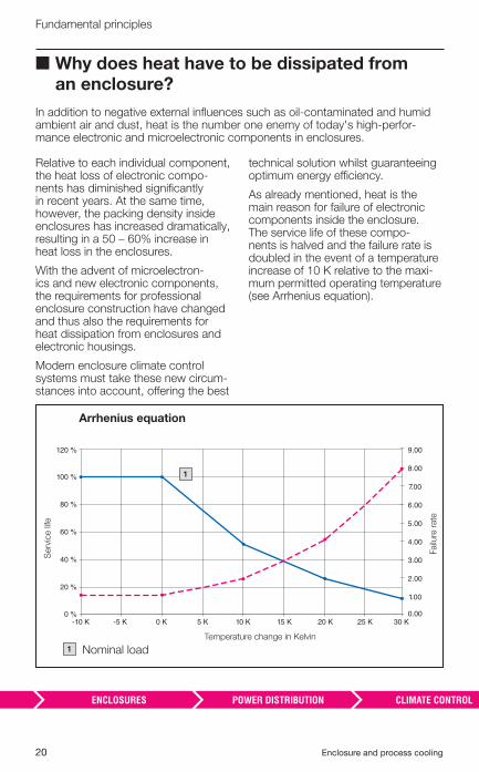
As already mentioned, heat is the main reason for failure of electronic components inside the enclosure. The service life of these compo-nents is halved and the failure rate is doubled in the event of a temperature increase of 10 K relative to the maxi-mum permitted operating temperature (see Arrhenius equation).
5 K 10 K 20 K-10 K -5 K 0 K 15 K 25 K 30 K0 %
40 %
20 %
60 %
80 %
100 %
120 % 9.00
8.00
7.00
6.00
5.00
4.00
3.00
2.00
1.00
0.00
Arrhenius equation
Temperature change in Kelvin
Serv
ice li
fe
Failu
re r
ate
1
Nominal load1
Enclosure and process cooling 21
Fundamental principles
■ Types of heat dissipation
Trouble-free operation and functioning of production lines is very heavily dependent on how the heat generated by electrical and electronic components is dissipated from the enclosure to the outside.
We distinguish three diff erent types/methods of heat transfer:
◾ Thermal conduction ◾ Convection ◾ Thermal radiation
In the case of enclosures and electronic housings, we are mainly concerned with thermal conduction and convection. With thermal radia-tion, heat is passed from one body to another in the form of radiation energy, without a medium material, and plays a minor role here.
Whether we are dealing with heat conduction or convection depends on whether the enclosure is open (air-permeable) or closed (air-tight). With an open enclosure, the heat (heat loss) can be dissipated from the enclosure by means of air circulation, i.e. thermal conduction, from inside to outside. If the enclosure has to remain closed, the heat can only be dissipated via the enclosure walls, i.e. through convec-tion.
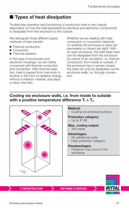
Cooling via enclosure walls, i.e. from inside to outside with a positive temperature diff erence Ti > Tu
Method: – � Cooling via enclosure surface
Protection category: – � Up to IP 68
Max. cooling output: – � 350 watts
Advantages: – � No additional costs – � High protection category
Disadvantages: – � Hotspots may occur in the
enclosure
22 Enclosure and process cooling
Fundamental principles
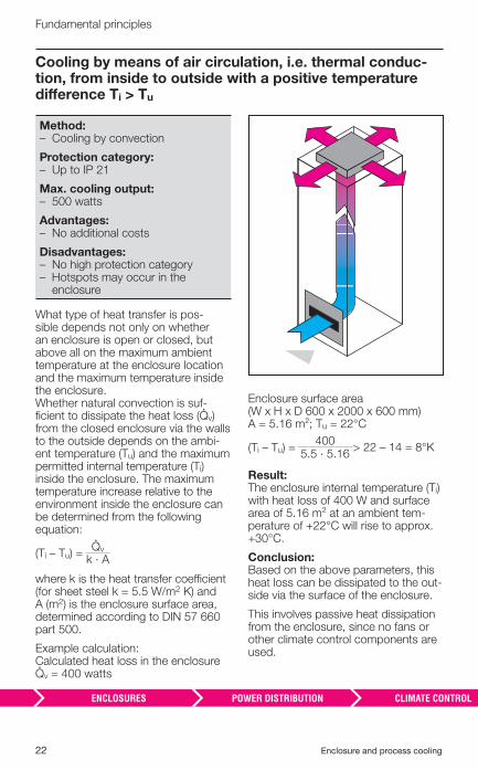
Cooling by means of air circulation, i.e. thermal conduc-tion, from inside to outside with a positive temperature diff erence Ti > Tu
Method: – � Cooling by convection
Protection category: – � Up to IP 21
Max. cooling output: – � 500 watts
Advantages: – � No additional costs
Disadvantages: – � No high protection category – � Hotspots may occur in the
enclosure
What type of heat transfer is pos-sible depends not only on whether an enclosure is open or closed, but above all on the maximum ambient temperature at the enclosure location and the maximum temperature inside the enclosure. Whether natural convection is suf-fi cient to dissipate the heat loss (�v) from the closed enclosure via the walls to the outside depends on the ambi-ent temperature (Tu) and the maximum permitted internal temperature (Ti) inside the enclosure. The maximum temperature increase relative to the environment inside the enclosure can be determined from the following equation:
(Ti – Tu) =�v
k · A
where k is the heat transfer coeffi cient (for sheet steel k = 5.5 W/m2 K) and A (m2) is the enclosure surface area, determined according to DIN 57 660 part 500.
Example calculation: Calculated heat loss in the enclosure �v = 400 watts
Enclosure surface area (W x H x D 600 x 2000 x 600 mm) A = 5.16 m²; Tu = 22°C
(Ti – Tu) =400
> 22 – 14 = 8°K5.5 · 5.16
Result: The enclosure internal temperature (Ti) with heat loss of 400 W and surface area of 5.16 m² at an ambient tem-perature of +22°C will rise to approx. +30°C.
Conclusion: Based on the above parameters, this heat loss can be dissipated to the out-side via the surface of the enclosure.
This involves passive heat dissipation from the enclosure, since no fans or other climate control components are used.
Enclosure and process cooling 23
Fundamental principles
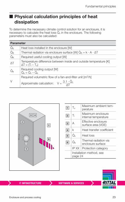
■ Physical calculation principles of heat dissipation
To determine the necessary climate control solution for an enclosure, it is necessary to calculate the heat loss �v in the enclosure. The following parameters must also be calculated:
Parameter
�V Heat loss installed in the enclosure [W]
�S Thermal radiation via enclosure surface [W] �S = k · A · ΔT
�K Required useful cooling output [W]
ΔTTemperature diff erence between inside and outside temperature [K] ΔT = (Ti – Tu)
�e Required cooling output [W]�e = �v – �s
V
Required volumetric fl ow of a fan-and-fi lter unit [m3/h]
Approximate calculation: V =3.1 · �v
ΔT
1
5
2
6
Tu Maximum ambient tem-perature
Ti Maximum enclosure internal temperature
AEff ective enclosure surface area (VDE)
k Heat transfer coeffi cient
�v Heat loss
�s Thermal radiation via enclosure surface
IP XX Protection category
Installation method, see page 24
1
2
3
4
5
6
3 4
24 Enclosure and process cooling
Fundamental principles
The maximum enclosure internal temperature (Ti) must be determined depending on the electrical and electronic components used in the enclosure.
According to IEC 60 204-1 “Safety of Machinery”, the electrical equipment of machines must be able to function correctly at the envisaged ambient air temperature. The minimum require-ment is correct operation at ambient temperatures of between +5°C and +40°C. As far as the recommended
enclosure internal temperature is concerned, an average value of +35°C has become the norm. This internal temperature also forms the basis for all calculations for necessary climate control solutions in enclosures.
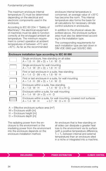
In addition to the physical values de-scribed above, the enclosure surface area must also be determined accord-ing to the installation type.
The corresponding requirements for each installation type are laid down in DIN VDE 0660 part 500/IEC 890.
Enclosure installation type according to IEC 60 890
Single enclosure, free-standing on all sides A = 1.8 · H · (W + D) + 1.4 · W · D
Single enclosure for wall mounting A = 1.4 · W · (H + D) + 1.8 · H · D
First or last enclosure in a suite, free-standingA = 1.4 · D · (W + H) + 1.8 · W · H
First or last enclosure in a suite, for wall mounting A = 1.4 · H · (W + D) + 1.4 · W · D
Enclosure within a suite, free-standing A = 1.8 · W · H + 1.4 · W · D + H · D
Enclosure within a suite, for wall mounting A = 1.4 · W · (H + D) + H · D
Enclosure within a suite, for wall mounting, covered roof surfacesA = 1.4 · W · H + 0.7 · W · D + H · D
A = Eff ective enclosure surface area [m2]W = Enclosure width [m]H = Enclosure height [m]D = Enclosure depth [m]
The radiating power from the en-closure to the environment or the irradiating power from the environment into the enclosure depends on the enclosure installation method.
An enclosure that is free-standing on all sides can dissipate a greater heat loss to the environment via its surface (with a positive temperature diff erence, Ti > Tu between internal and external temperature) than an enclosure sited in a niche or integrated into a machine.
Enclosure and process cooling 25
Fundamental principles
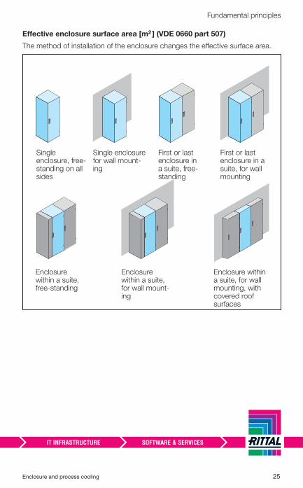
Effective enclosure surface area [m2 ] (VDE 0660 part 507)
The method of installation of the enclosure changes the eff ective surface area.
Single enclosure, free-standing on all sides
Single enclosure for wall mount-ing
First or last enclosure in a suite, free-standing
First or last enclosure in a suite, for wall mounting
Enclosure within a suite, free-standing
Enclosure within a suite, for wall mount-ing
Enclosure within a suite, for wall mounting, with covered roof surfaces
26 Enclosure and process cooling
Fundamental principles
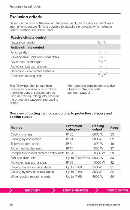
Exclusion criteria
Based on the ratio of the ambient temperature (Tu) to the required enclosure internal temperature (Ti), it is possible to establish in advance which climate control method should be used.
Passive climate control
Natural convection Ti > Tu
Active climate control
Air circulation Ti > Tu
Fan-and-fi lter units and outlet fi lters Ti > Tu
Air/air heat exchangers Ti > Tu
Air/water heat exchangers Ti < Tu
Recooling / cold-water systems Ti < Tu
Enclosure cooling units Ti < Tu
The following table should help provide an overview of which type of climate control solution can be used and when, taking into account the protection category and cooling output.
For a detailed explanation of active climate control methods, see from page 31.
Overview of cooling methods according to protection category and cooling output
MethodProtection category
Cooling output
Page
Cooling via fans IP 20 8000 W 33
Cooling by convection IP 21 500 W 32
Thermoelectric cooler IP 54 1000 W 40
Air/air heat exchangers IP 54 1000 W 37
Compressor-based climate control units IP 54 10000 W 53
Fan-and-fi lter units Up to IP 54/IP 55 2000 W 33
Air/water heat exchangers IP 55 10000 W 42
Cooling via enclosure surface Up to IP 68 250 W 21
Cooling by forced air circulation Up to IP 68 350 W 32
Water-cooled mounting plate Up to IP 68 3000 W 50
Enclosure and process cooling 27
Fundamental principles
28 Enclosure and process cooling
Fundamental principles
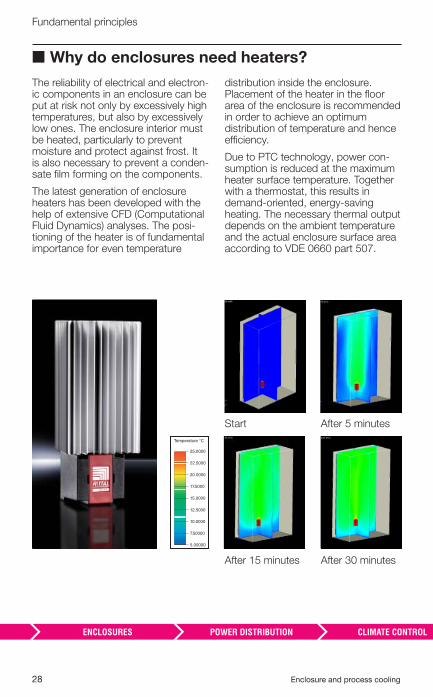
■ Why do enclosures need heaters?
The reliability of electrical and electron-ic components in an enclosure can be put at risk not only by excessively high temperatures, but also by excessively low ones. The enclosure interior must be heated, particularly to prevent moisture and protect against frost. It is also necessary to prevent a conden-sate fi lm forming on the components.
The latest generation of enclosure heaters has been developed with the help of extensive CFD (Computational Fluid Dynamics) analyses. The posi-tioning of the heater is of fundamental importance for even temperature
distribution inside the enclosure. Placement of the heater in the fl oor area of the enclosure is recommended in order to achieve an optimum distribution of temperature and hence effi ciency.
Due to PTC technology, power con-sumption is reduced at the maximum heater surface temperature. Together with a thermostat, this results in demand-oriented, energy-saving heating. The necessary thermal output depends on the ambient temperature and the actual enclosure surface area according to VDE 0660 part 507.
25.0000
Temperature °C
22.5000
20.0000
17.5000
15.0000
12.5000
10.0000
7.50000
5.00000
After 15 minutes After 30 minutes
Start After 5 minutes
Enclosure and process cooling 29
Fundamental principles
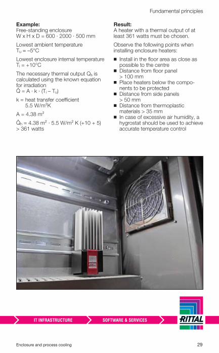
Example: Free-standing enclosure W x H x D = 600 · 2000 · 500 mm
Lowest ambient temperature Tu = –5°C
Lowest enclosure internal temperature Ti = +10°C
The necessary thermal output Qs is calculated using the known equation for irradiation � = A · k · (Ti – Tu)
k = heat transfer coeffi cient 5.5 W/m²K
A = 4.38 m²
�h = 4.38 m² · 5.5 W/m² K (+10 + 5) > 361 watts
Result: A heater with a thermal output of at least 361 watts must be chosen.
Observe the following points when installing enclosure heaters:
◾ Install in the fl oor area as close as possible to the centre
◾ Distance from fl oor panel > 100 mm
◾ Place heaters below the compo-nents to be protected
◾ Distance from side panels> 50 mm
◾ Distance from thermoplastic materials > 35 mm
◾ In case of excessive air humidity, a hygrostat should be used to achieve accurate temperature control
30 Enclosure and process cooling
Enclosure and process cooling 31
Active heat dissipation
Heat dissipation through forced air circulation ................ 32
Heat dissipation through fan-and-fi lter units ................... 33◾ Calculation of volumetric fl ow of a fan relative to the installation height ....... 35
Heat dissipation with air/air heat exchangers .................. 37
Heat dissipation with thermoelectric cooling ................... 40
Heat dissipation with air/water heat exchangers ............. 42◾ Benefi ts of water cooling ........................................................................... 44
◾ Effi ciency comparison, cooling units – chillers with heat exchangers ...... 46
◾ Dissipation of high heat losses (cooling outputs > 10 kW) ...................... 48
Direct water cooling ............................................................ 50
Active climate control with enclosure cooling units ....... 53◾ Cooling unit technology ............................................................................ 54
◾ Why use electrical condensate evaporation? ............................................ 59
General overview ................................................................. 61
Design and calculation of climate control solutions using Therm software ......................................................... 62
32 Enclosure and process cooling
Active heat dissipation
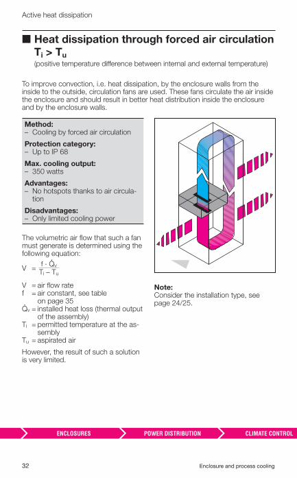
■ Heat dissipation through forced air circulation Ti > Tu
(positive temperature diff erence between internal and external temperature)
To improve convection, i.e. heat dissipation, by the enclosure walls from the inside to the outside, circulation fans are used. These fans circulate the air inside the enclosure and should result in better heat distribution inside the enclosure and by the enclosure walls.
Method: – � Cooling by forced air circulation
Protection category: – � Up to IP 68
Max. cooling output: – � 350 watts
Advantages: – � No hotspots thanks to air circula-
tion
Disadvantages: – � Only limited cooling power
The volumetric air fl ow that such a fan must generate is determined using the following equation:
V =f · �v Ti – Tu
V = air fl ow ratef = air constant, see table
on page 35�v = installed heat loss (thermal output
of the assembly)Ti = permitted temperature at the as-
semblyTu = aspirated air
However, the result of such a solution is very limited.
Note:Consider the installation type, see page 24/25.
Enclosure and process cooling 33
Active heat dissipation
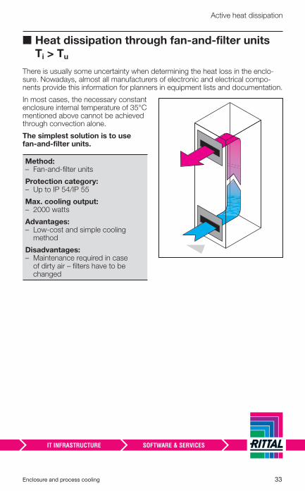
■ Heat dissipation through fan-and-fi lter units Ti > Tu
There is usually some uncertainty when determining the heat loss in the enclo-sure. Nowadays, almost all manufacturers of electronic and electrical compo-nents provide this information for planners in equipment lists and documentation.
In most cases, the necessary constant enclosure internal temperature of 35°C mentioned above cannot be achieved through convection alone.
The simplest solution is to use fan-and-fi lter units.
Method: – � Fan-and-fi lter units
Protection category: – � Up to IP 54/IP 55
Max. cooling output: – � 2000 watts
Advantages: – � Low-cost and simple cooling
method
Disadvantages: – � Maintenance required in case
of dirty air – fi lters have to be changed
34 Enclosure and process cooling
Active heat dissipation
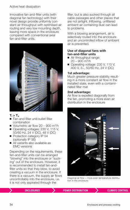
Innovative fan-and-fi lter units (with diagonal fan technology) with their novel design provide uniformly con-stant air throughput with optimised air routing and very low mounting depth, leaving more space in the enclosure compared with conventional axial fan-and-fi lter units.
Ti > Tu ◾ Fan-and-fi lter unit/outlet fi lter combination
◾ Volumetric air fl ow 20 – 900 m3/h ◾ Operating voltages: 230 V, 115 V, 50/60 Hz, 24 V (DC), 48 V (DC)
◾ Protection category IP 54 (optionally IP 56)
◾ All variants also available as EMC versions
Depending on the requirements, these fan-and-fi lter units can be arranged “blowing” into the enclosure or “suck-ing” out of the enclosure. However, it is recommended to install fan-and-fi lter units so that they blow, to avoid creating a vacuum in the enclosure. If there is a vacuum, the supply air fl ows uncontrollably into the enclosure, i.e. it is not only aspirated through the
fi lter, but is also sucked through all cable passages and other places that are not airtight. Infl owing, unfi ltered ambient air containing dust can lead to problems.
With a blowing arrangement, air is selectively routed into the enclosure and an uncontrolled infl ow of ambient air is prevented.
Use of diagonal fans with fan-and-fi lter units
◾ Air throughput range: 20 – 900 m3/h
◾ Operating voltage: 230 V, 115 V, 400 V, 3~, 50/60 Hz, 24 V (DC)
1st advantage: Much greater pressure stability result-ing in a more constant air fl ow in the installed state, even with a contami-nated fi lter mat
2nd advantage: Air fl ow is expelled diagonally from the fan, promoting a more even air distribution in the enclosure
Diagonal air fl ow = more even temperature distribu-tion in the enclosure
Enclosure and process cooling 35
Active heat dissipation
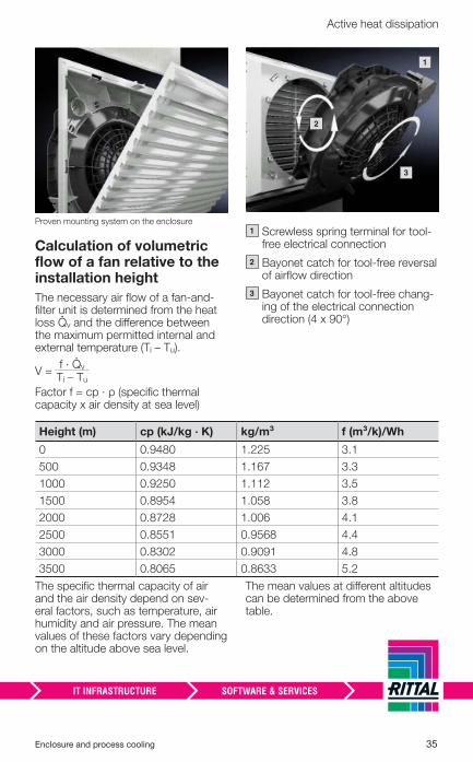
Proven mounting system on the enclosure
Calculation of volumetric fl ow of a fan relative to the installation height
The necessary air fl ow of a fan-and-fi lter unit is determined from the heat loss �v and the diff erence between the maximum permitted internal and external temperature (Ti – Tu).
V =f · �v Ti – Tu
Factor f = cp · ρ (specifi c thermal capacity x air density at sea level)
2
3
1
– � Screwless spring terminal for tool-free electrical connection
– � Bayonet catch for tool-free reversal of airfl ow direction
– � Bayonet catch for tool-free chang-ing of the electrical connection direction (4 x 90°)
Height (m) cp (kJ/kg · K) kg/m³ f (m³/k)/Wh
0 0.9480 1.225 3.1
500 0.9348 1.167 3.3
1000 0.9250 1.112 3.5
1500 0.8954 1.058 3.8
2000 0.8728 1.006 4.1
2500 0.8551 0.9568 4.4
3000 0.8302 0.9091 4.8
3500 0.8065 0.8633 5.2
The specifi c thermal capacity of air and the air density depend on sev-eral factors, such as temperature, air humidity and air pressure. The mean values of these factors vary depending on the altitude above sea level.
The mean values at diff erent altitudes can be determined from the above table.
1
2
3
36 Enclosure and process cooling
Active heat dissipation
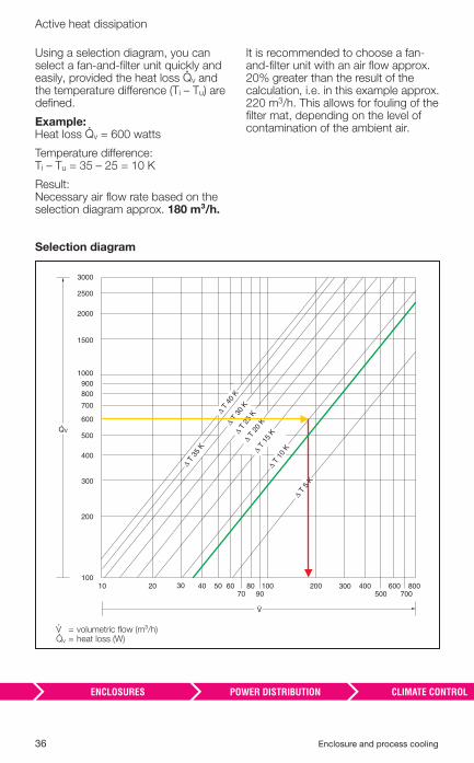
Using a selection diagram, you can select a fan-and-fi lter unit quickly and easily, provided the heat loss �v and the temperature diff erence (Ti – Tu) are defi ned.
Example: Heat loss �v = 600 watts
Temperature diff erence: Ti – Tu = 35 – 25 = 10 K
Result: Necessary air fl ow rate based on the selection diagram approx. 180 m³/h.
It is recommended to choose a fan-and-fi lter unit with an air fl ow approx. 20% greater than the result of the calculation, i.e. in this example approx. 220 m3/h. This allows for fouling of the fi lter mat, depending on the level of contamination of the ambient air.
Selection diagram
V.
QV.
100
200
300
400
500
600
700
900800
1000
1500
2000
3000
2500
Δ T 3
5 K
Δ T 4
0 K
Δ T 3
0 K
Δ T 2
0 K
Δ T 1
5 K
Δ T 1
0 K
Δ T 5
K
Δ T 2
5 K
30 5070 90
300500 700
10 20 40 60 80 100 200 400 600 800
� = volumetric fl ow (m³/h)�v = heat loss (W)
Enclosure and process cooling 37
Active heat dissipation
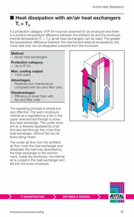
■ Heat dissipation with air/air heat exchangers Ti > Tu
If a protection category of IP 54 must be observed for an enclosure and there is a positive temperature diff erence between the ambient air and the enclosure internal temperature (Ti > Tu), air/air heat exchangers can be used. The greater the temperature diff erence between the internal and external temperature, the more heat loss can be dissipated outwards from the enclosure.
Method: – � Air/air heat exchangers
Protection category: – � Up to IP 54
Max. cooling output: – � 1000 watts
Advantages: – � Relatively low-maintenance
compared with fan-and-fi lter units
Disadvantages: – � Effi ciency is lower than with
fan-and-fi lter units
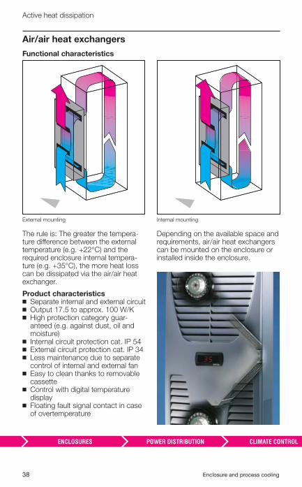
The operating principle is simple but very eff ective. The warm enclosure internal air is aspirated by a fan in the upper area and led through a cross-fl ow heat exchanger. The cooler ambi-ent air is likewise aspirated by a fan and also led through this cross-fl ow heat exchanger, without the two air fl ows being mixed.
The cooler air fl ow from the ambient air fl ow cools the heat exchanger and dissipates the heat loss absorbed by the heat exchanger to the environ-ment. Inside the enclosure, the internal air is cooled in the heat exchanger and led into the lower enclosure.
38 Enclosure and process cooling
Active heat dissipation
Air/air heat exchangers
Functional characteristics
External mounting
The rule is: The greater the tempera-ture diff erence between the external temperature (e.g. +22°C) and the required enclosure internal tempera-ture (e.g. +35°C), the more heat loss can be dissipated via the air/air heat exchanger.
Product characteristics ◾ Separate internal and external circuit ◾ Output 17.5 to approx. 100 W/K ◾ High protection category guar-anteed (e.g. against dust, oil and moisture)
◾ Internal circuit protection cat. IP 54 ◾ External circuit protection cat. IP 34 ◾ Less maintenance due to separate control of internal and external fan
◾ Easy to clean thanks to removable cassette
◾ Control with digital temperature display
◾ Floating fault signal contact in case of overtemperature
Internal mounting
Depending on the available space and requirements, air/air heat exchangers can be mounted on the enclosure or installed inside the enclosure.
Enclosure and process cooling 39
Active heat dissipation
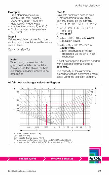
Example: – � Free-standing enclosure
Width = 600 mm, height = 2000 mm, depth = 500 mm
– � Heat loss �v = 900 watts – � Ambient temperature Tu = 25°C– � Enclosure internal temperature
Ti = 35°C
Step 1 Calculate radiation power from the enclosure to the outside via the enclo-sure surface.
�s = k · A · (Ti – Tu)
Step 2 Calculate enclosure surface area A (m2) according to VDE 0660 part 500 based on the formula A = 1.8 · H · (W + D) + 1.4 · W · D
A = 1.8 · 2.0 · (0.6 + 0.5) + 1.4 · 0.6 · 0.5
A = 4.38 m²
�s = 5.5 · 4.38 · 10 = 242 watts = radiation power
�e = �v – �s = 900 W – 242 W = 658 watts = heat loss that must still be
dissipated via the air/air heat exchanger
A heat exchanger is therefore needed with a specifi c thermal output of 65.8 W/K.
The capacity of the air/air heat exchanger can be determined more easily using the selection diagram.
Air/air heat exchanger selection diagram
qw
ΔT
A
5 010152025
30
40
50
6070
10 30 50 70
024681012
3000 2000 1000 0 20 40 60 80
QV.
ΔT = temperature diff erence (K)�v = heat loss (W)qw = specifi c thermal output (W/K) A = enclosure surface area according to VDE 0660 part 500 (m2) k = heat transfer coeffi cient (W/m2 K), for sheet steel k = 5.5 W/m2 K
Note:When using the selection dia-gram, heat radiation is not taken into account; this allows the heat exchanger capacity reserve to be determined.
40 Enclosure and process cooling
Active heat dissipation
■ Heat dissipation with thermoelectric cooling Ti < Tu
Thermoelectric coolers are also known as Peltier coolers. The French physicist Jean Charles Peltier discovered this “thermal eff ect” in 1834.
Thermoelectric cooling with Peltier cooling units
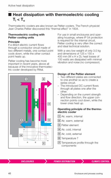
Principle If a direct electric current fl ows through a conductor circuit made of two diff erent metals, one contact point cools down, while the other contact point heats up.
Peltier cooling has become more important in recent years, above all because of the innovative thermoelec-tric cooler developed by Rittal.
A B
B
C
1 2
3
4 5
6
7
For use in small enclosures and oper-ating housings, where IP 54 protection is required for the internal circuit, Peltier cooling is very often the correct and ideal technical solution.
With a very low weight of only 3.0 kg and dimensions of 125 x 155 x 400 mm (W x H x D), heat losses of 100 watts are dissipated with minimal vibration and noise (no compressor).
Design of the Peltier element – � Two diff erent plates are connected
to one another so as to create a series circuit.
– � The introduced DC current fl ows through all plates one after the other.
– � Depending on the current strength and fl ow direction, the upper con-nection points cool down, while the lower ones heat up.
Operating principle of the thermo-electric cooler
– � Air, warm, internal
– � Air, warm, external
– � Peltier element
– � Air, cold, internal
– � Air, cold, external
– � Temperature T
– � Temperature profi le through the components
1
2
3
4
5
6
7
Enclosure and process cooling 41
Active heat dissipation
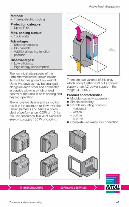
Method: – � Thermoelectric cooling
Protection category: – � Up to IP 54
Max. cooling output: – � 1000 watts
Advantages: – � Small dimensions– � DC-capable– � Additional heating function
possible
Disadvantages: – � Low effi ciency – � High energy consumption
The technical advantages of the Rittal thermoelectric cooler include its modular design and low weight. Up to fi ve devices may be arranged alongside each other and connected in parallel, allowing synchronised control of the units in both cooling and heating operation.
The innovative design and air routing result in the optimum air fl ow over the Peltier elements and hence a coeffi -cient of performance (COP) of 1.0, i.e. the unit consumes 100 W of electrical energy to supply 100 W of cooling.
There are two variants of this unit, which accept either a 24 V DC power supply or an AC power supply in the range 94 – 264 V.
Product characteristics ◾ Modular capacity expansion ◾ Simple scalability ◾ Flexible mounting position: – horizontal – vertical – built-in– built-on
◾ Complete unit ready for connection
42 Enclosure and process cooling
Active heat dissipation
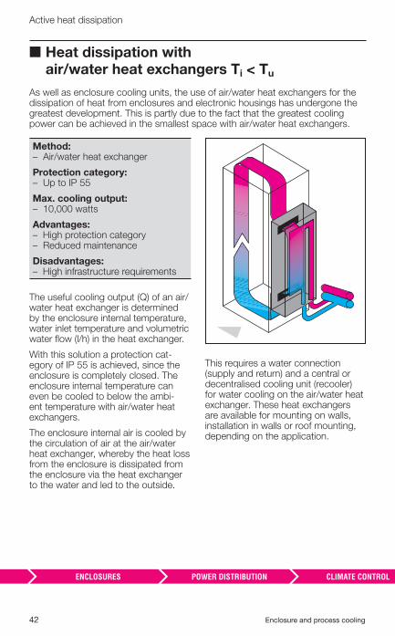
■ Heat dissipation with air/water heat exchangers Ti < Tu
As well as enclosure cooling units, the use of air/water heat exchangers for the dissipation of heat from enclosures and electronic housings has undergone the greatest development. This is partly due to the fact that the greatest cooling power can be achieved in the smallest space with air/water heat exchangers.
Method: – � Air/water heat exchanger
Protection category: – � Up to IP 55
Max. cooling output: – � 10,000 watts
Advantages: – � High protection category– � Reduced maintenance
Disadvantages: – � High infrastructure requirements
The useful cooling output (Q) of an air/water heat exchanger is determined by the enclosure internal temperature, water inlet temperature and volumetric water fl ow (l/h) in the heat exchanger.
With this solution a protection cat-egory of IP 55 is achieved, since the enclosure is completely closed. The enclosure internal temperature can even be cooled to below the ambi-ent temperature with air/water heat exchangers.
The enclosure internal air is cooled by the circulation of air at the air/water heat exchanger, whereby the heat loss from the enclosure is dissipated from the enclosure via the heat exchanger to the water and led to the outside.
This requires a water connection (supply and return) and a central or decentralised cooling unit (recooler) for water cooling on the air/water heat exchanger. These heat exchangers are available for mounting on walls, installation in walls or roof mounting, depending on the application.
Enclosure and process cooling 43
Active heat dissipation
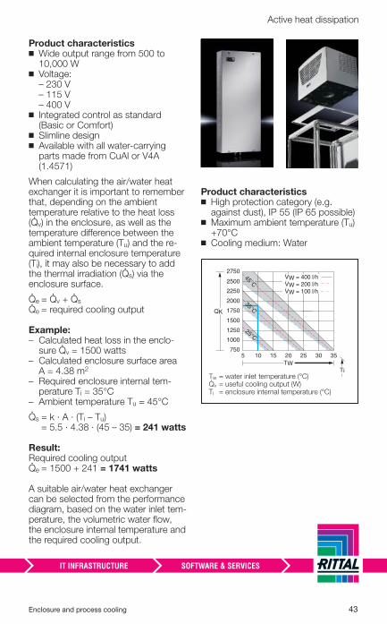
Product characteristics ◾ Wide output range from 500 to 10,000 W
◾ Voltage: – 230 V – 115 V – 400 V
◾ Integrated control as standard (Basic or Comfort)
◾ Slimline design ◾ Available with all water-carrying parts made from CuAl or V4A (1.4571)
When calculating the air/water heat exchanger it is important to remember that, depending on the ambient temperature relative to the heat loss (�v) in the enclosure, as well as the temperature diff erence between the ambient temperature (Tu) and the re-quired internal enclosure temperature (Ti), it may also be necessary to add the thermal irradiation (�s) via the enclosure surface.
�e = �v + �s �e = required cooling output
Example: – � Calculated heat loss in the enclo-
sure �v = 1500 watts– � Calculated enclosure surface area
A = 4.38 m2 – � Required enclosure internal tem-
perature Ti = 35°C– � Ambient temperature Tu = 45°C
�s = k · A · (Ti – Tu) = 5.5 · 4.38 · (45 – 35) = 241 watts
Result: Required cooling output �e = 1500 + 241 = 1741 watts
A suitable air/water heat exchanger can be selected from the performance diagram, based on the water inlet tem-perature, the volumetric water fl ow, the enclosure internal temperature and the required cooling output.
Product characteristics ◾ High protection category (e.g. against dust), IP 55 (IP 65 possible)
◾ Maximum ambient temperature (Tu) +70°C
◾ Cooling medium: Water
5750
1000
1250
1500
1750
2000
2250
2500
2750
10 15 20 25 30 35
Ti
QK.
TW
VW = 400 l/hVW = 200 l/hVW = 100 l/h
.
.
.
45°C
25°C
35°C
Tw = water inlet temperature (°C) �v = useful cooling output (W) Ti = enclosure internal temperature (°C)
44 Enclosure and process cooling
Active heat dissipation
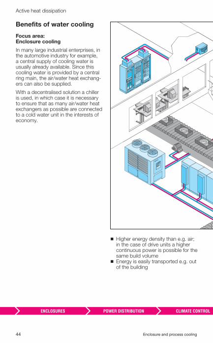
Benefi ts of water cooling
Focus area:Enclosure cooling
In many large industrial enterprises, in the automotive industry for example, a central supply of cooling water is usually already available. Since this cooling water is provided by a central ring main, the air/water heat exchang-ers can also be supplied.
With a decentralised solution a chiller is used, in which case it is necessary to ensure that as many air/water heat exchangers as possible are connected to a cold water unit in the interests of economy.
◾ Higher energy density than e.g. air; in the case of drive units a higher continuous power is possible for the same build volume
◾ Energy is easily transported e.g. out of the building
Enclosure and process cooling 45
Active heat dissipation
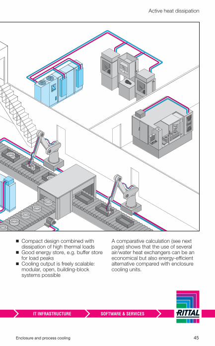
◾ Compact design combined with dissipation of high thermal loads
◾ Good energy store, e.g. buff er store for load peaks
◾ Cooling output is freely scalable: modular, open, building-block systems possible
A comparative calculation (see next page) shows that the use of several air/water heat exchangers can be an economical but also energy-effi cient alternative compared with enclosure cooling units.
46 Enclosure and process cooling
Active heat dissipation
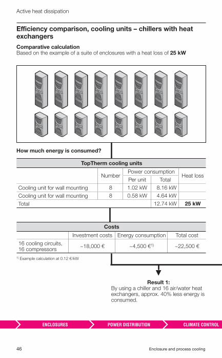
Effi ciency comparison, cooling units – chillers with heat exchangers
Comparative calculation Based on the example of a suite of enclosures with a heat loss of 25 kW
Result 1: By using a chiller and 16 air/water heat exchangers, approx. 40% less energy is consumed.
1) Example calculation at 0.12 €/kW
Costs
Investment costs Energy consumption Total cost
16 cooling circuits,16 compressors
~18,000 € ~4,500 €1) ~22,500 €
How much energy is consumed?
TopTherm cooling units
NumberPower consumption
Heat lossPer unit Total
Cooling unit for wall mounting 8 1.02 kW 8.16 kW
Cooling unit for wall mounting 8 0.58 kW 4.64 kW
Total 12.74 kW 25 kW
Enclosure and process cooling 47
Active heat dissipation
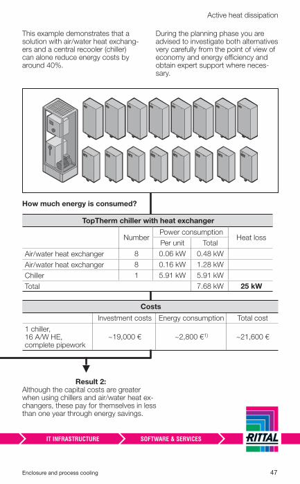
This example demonstrates that a solution with air/water heat exchang-ers and a central recooler (chiller) can alone reduce energy costs by around 40%.
During the planning phase you are advised to investigate both alternatives very carefully from the point of view of economy and energy effi ciency and obtain expert support where neces-sary.
Result 2: Although the capital costs are greater when using chillers and air/water heat ex-changers, these pay for themselves in less than one year through energy savings.
Costs
Investment costs Energy consumption Total cost
1 chiller, 16 A/W HE, complete pipework
~19,000 € ~2,800 €1) ~21,600 €
How much energy is consumed?
TopTherm chiller with heat exchanger
NumberPower consumption
Heat lossPer unit Total
Air/water heat exchanger 8 0.06 kW 0.48 kW
Air/water heat exchanger 8 0.16 kW 1.28 kW
Chiller 1 5.91 kW 5.91 kW
Total 7.68 kW 25 kW
48 Enclosure and process cooling
Active heat dissipation
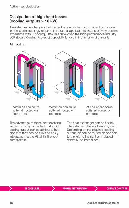
Dissipation of high heat losses (cooling outputs > 10 kW)
Air/water heat exchangers that can achieve a cooling output spectrum of over 10 kW are increasingly required in industrial applications. Based on very positive experience with IT cooling, Rittal has developed the high-performance Industry LCP (Liquid Cooling Package) especially for use in industrial environments.
Air routing
The advantage of these heat exchang-ers lies not only in the fact that a high cooling output can be achieved, but also that they can be fully and easily integrated into the Rittal TS 8 enclo-sure system.
The heat exchanger can be fl exibly integrated into the enclosure system. Depending on the required cooling output, air can be routed on one side to the left, to the right or, if placed centrally, on both sides.
Within an enclosure suite, air routed on both sides
Within an enclosure suite, air routed on one side
At end of enclosure suite, air routed on one side
Enclosure and process cooling 49
Active heat dissipation
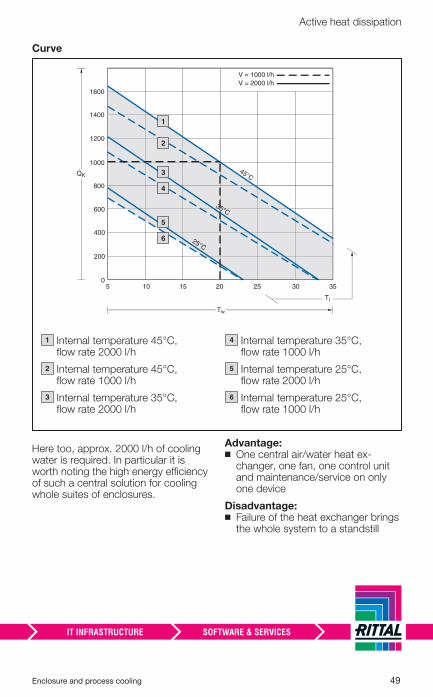
Curve
Here too, approx. 2000 l/h of cooling water is required. In particular it is worth noting the high energy effi ciency of such a central solution for cooling whole suites of enclosures.
Advantage: ◾ One central air/water heat ex-changer, one fan, one control unit and maintenance/service on only one device
Disadvantage: ◾ Failure of the heat exchanger brings the whole system to a standstill
1400
1600
1200
1000
800
600
400
200
05 10 15 20 25 30 35
Tw
QK.
25°C
35°C
45°C
Ti
V = 1000 l/hV = 2000 l/h
– � 1
– � 2
– � 3
– � 4
– � 5
– � 6
– � Internal temperature 45°C, fl ow rate 2000 l/h
– � Internal temperature 45°C, fl ow rate 1000 l/h
– � Internal temperature 35°C, fl ow rate 2000 l/h
– � Internal temperature 35°C, fl ow rate 1000 l/h
– � Internal temperature 25°C, fl ow rate 2000 l/h
– � Internal temperature 25°C, fl ow rate 1000 l/h
1
2
3
4
5
6
50 Enclosure and process cooling
Active heat dissipation
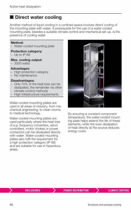
■ Direct water cooling
Another method of liquid cooling in a confi ned space involves direct cooling of the mounting plate with water. A prerequisite for the use of a water-cooled mounting plate, besides a suitable climate-control and mechanical set-up, is the presence of cooling water.
Method: – � Water-cooled mounting plate
Protection category: – � Up to IP 68
Max. cooling output: – � 3000 watts
Advantages: – � High protection category– � No maintenance
Disadvantages: – � Only 70% of the heat loss can be
dissipated, the remainder via other climate-control methods
– � High infrastructure requirements
Water-cooled mounting plates are used in all areas of industry, from me-chanical engineering, to clean rooms, to medical technology.
Water-cooled mounting plates are used particularly where the heat loss of e.g. frequency converters, servo controllers, motor chokes or power contactors can be dissipated directly with water. Water-cooled mounting plates also fulfi l the requirement for a high protection category (IP 68) and are suitable for use in hazardous areas.
By ensuring a constant component temperature, the water-cooled mount-ing plate helps extend the life of these elements, while the even dissipation of heat directly at the source reduces energy costs.
Enclosure and process cooling 51
Active heat dissipation
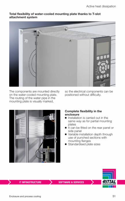
Total flexibility of water-cooled mounting plate thanks to T-slot attachment system
The components are mounted directly on the water-cooled mounting plate. The routing of the water pipe in the mounting plate is visually marked,
so the electrical components can be positioned without diffi culty.
Complete fl exibility in the enclosure
◾ Installation is carried out in the same way as for partial mounting plates
◾ It can be fi tted on the rear panel or side panel
◾ Variable installation depth through use of punched sections with mounting fl anges
◾ Standardised plate sizes
52 Enclosure and process cooling
Active heat dissipation
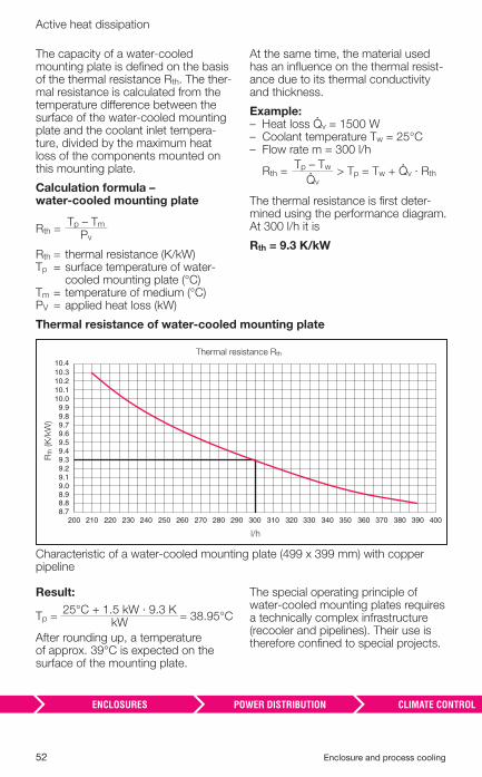
The capacity of a water-cooled mounting plate is defi ned on the basis of the thermal resistance Rth. The ther-mal resistance is calculated from the temperature diff erence between the surface of the water-cooled mounting plate and the coolant inlet tempera-ture, divided by the maximum heat loss of the components mounted on this mounting plate.
Calculation formula –water-cooled mounting plate
Rth =Tp – Tm
Pv
Rth = thermal resistance (K/kW)Tp = surface temperature of water-
cooled mounting plate (°C)Tm = temperature of medium (°C)PV = applied heat loss (kW)
At the same time, the material used has an infl uence on the thermal resist-ance due to its thermal conductivity and thickness.
Example: – � Heat loss �v = 1500 W – � Coolant temperature Tw = 25°C – � Flow rate m = 300 l/h
Rth =Tp – Tw > Tp = Tw + �v · Rth
�v
The thermal resistance is fi rst deter-mined using the performance diagram. At 300 l/h it is
Rth = 9.3 K/kW
Thermal resistance of water-cooled mounting plate
Thermal resistance Rth
Rth
(K
/kW
)
8.78.88.99.09.19.29.39.49.59.69.79.89.9
10.010.110.210.310.4
200 210 220 230 240 250 260 270 280 290 300 310 320 330 340 350 370 380 390 400360
l/h
Characteristic of a water-cooled mounting plate (499 x 399 mm) with copper pipeline
Result:
Tp =25°C + 1.5 kW · 9.3 K
= 38.95°CkW
After rounding up, a temperature of approx. 39°C is expected on the surface of the mounting plate.
The special operating principle of water-cooled mounting plates requires a technically complex infrastructure (recooler and pipelines). Their use is therefore confi ned to special projects.
Enclosure and process cooling 53
Active heat dissipation
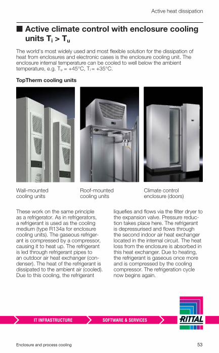
■ Active climate control with enclosure cooling units Ti > Tu
The world's most widely used and most fl exible solution for the dissipation of heat from enclosures and electronic cases is the enclosure cooling unit. The enclosure internal temperature can be cooled to well below the ambient temperature, e.g. Tu = +45°C, Ti = +35°C.
TopTherm cooling units
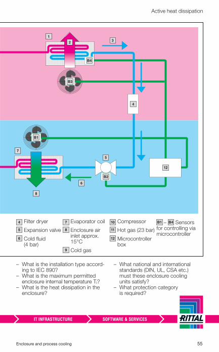
These work on the same principle as a refrigerator. As in refrigerators, a refrigerant is used as the cooling medium (type R134a for enclosure cooling units). The gaseous refriger-ant is compressed by a compressor, causing it to heat up. The refrigerant is led through refrigerant pipes to an outdoor air heat exchanger (con-denser). The heat of the refrigerant is dissipated to the ambient air (cooled). Due to this cooling, the refrigerant
liquefi es and fl ows via the fi lter dryer to the expansion valve. Pressure reduc-tion takes place here. The refrigerant is depressurised and fl ows through the second indoor air heat exchanger located in the internal circuit. The heat loss from the enclosure is absorbed in this heat exchanger. Due to heating, the refrigerant is gaseous once more and is compressed by the cooling compressor. The refrigeration cycle now begins again.
Wall-mounted cooling units
Roof-mounted cooling units
Climate control enclosure (doors)
54 Enclosure and process cooling
Active heat dissipation
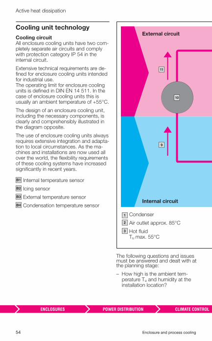
Cooling unit technology
Cooling circuitAll enclosure cooling units have two com-pletely separate air circuits and comply with protection category IP 54 in the internal circuit.
Extensive technical requirements are de-fi ned for enclosure cooling units intended for industrial use. The operating limit for enclosure cooling units is defi ned in DIN EN 14 511. In the case of enclosure cooling units this is usually an ambient temperature of +55°C.
The design of an enclosure cooling unit, including the necessary components, is clearly and comprehensibly illustrated in the diagram opposite.
The use of enclosure cooling units always requires extensive integration and adapta-tion to local circumstances. As the ma-chines and installations are now used all over the world, the fl exibility requirements of these cooling systems have increased signifi cantly in recent years.
– � Internal temperature sensor
– � Icing sensor
– � External temperature sensor
– � Condensation temperature sensor
B1
B2
B3
B4
The following questions and issues must be answered and dealt with at the planning stage:
– � How high is the ambient tem-perature Tu and humidity at the installation location?
– � Condenser
– � Air outlet approx. 85°C
– � Hot fl uid Tu max. 55°C
1
2
3
– � 11
– � 10
– � 9
External circuit
Internal circuit
Enclosure and process cooling 55
Active heat dissipation
– � 7
– � What is the installation type accord-ing to IEC 890?
– � What is the maximum permitted enclosure internal temperature Ti?
– � What is the heat dissipation in the enclosure?
– � What national and international standards (DIN, UL, CSA etc.) must these enclosure cooling units satisfy?
– � What protection category is required?
– � Filter dryer
– � Expansion valve
– � Cold fl uid (4 bar)
– � Evaporator coil
– � Enclosure air inlet approx. 15°C
– � Cold gas
– � Compressor
– � Hot gas (23 bar)
– � Microcontroller box
– B4 Sensors for controlling via microcontroller
4
5
6
7
8
9
10
11
12
B1
– �B4
– � 1
– � 2– � 3
– � 4
– � 5
– � 6
– � 12
– � 8
– �B1
– �B3
– �B2
56 Enclosure and process cooling
Active heat dissipation
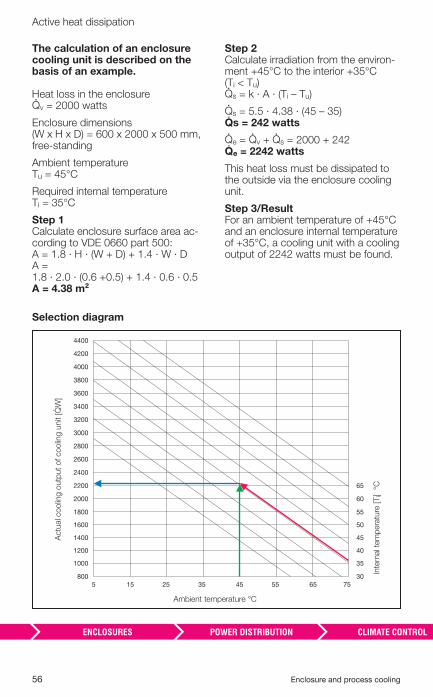
The calculation of an enclosure cooling unit is described on the basis of an example.
Heat loss in the enclosure�v = 2000 watts
Enclosure dimensions(W x H x D) = 600 x 2000 x 500 mm, free-standing
Ambient temperature Tu = 45°C
Required internal temperature Ti = 35°C
Step 1 Calculate enclosure surface area ac-cording to VDE 0660 part 500: A = 1.8 · H · (W + D) + 1.4 · W · D A = 1.8 · 2.0 · (0.6 +0.5) + 1.4 · 0.6 · 0.5A = 4.38 m²
Step 2 Calculate irradiation from the environ-ment +45°C to the interior +35°C (Ti < Tu) �s = k · A · (Ti – Tu)
�s = 5.5 · 4.38 · (45 – 35) �s = 242 watts
�e = �v + �s = 2000 + 242 �e = 2242 watts
This heat loss must be dissipated to the outside via the enclosure cooling unit.
Step 3/Result For an ambient temperature of +45°C and an enclosure internal temperature of +35°C, a cooling unit with a cooling output of 2242 watts must be found.
Selection diagram
155 25 35 45 55 65 75
4000
3800
3400
3600
3200
3000
2800
2600
2400
2200
2000
1800
1600
1200
1400
800
1000
4200
4400
65
60
55
50
40
45
30
35
Actu
al c
oolin
g o
utp
ut
of coolin
g u
nit [�
W]
Ambient temperature °C
Inte
rnal t
em
pera
ture
[T
i] °
C
Enclosure and process cooling 57
Active heat dissipation
From the two reference variables of ambient temperature 45°C and enclosure internal temperature 35°C, one can determine the appropriate cooling unit (wall or roof-mounted) from a cooling performance diagram. Rittal has developed the “Therm” calculation program to simplify the design and calculation of enclosure cooling units and other climate control components.
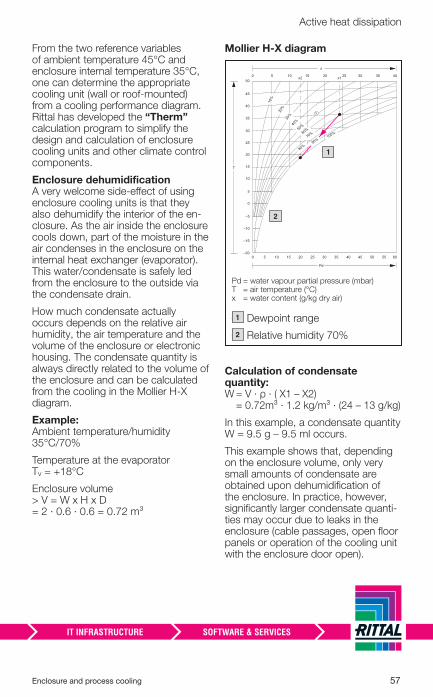
Enclosure dehumidifi cation A very welcome side-eff ect of using enclosure cooling units is that they also dehumidify the interior of the en-closure. As the air inside the enclosure cools down, part of the moisture in the air condenses in the enclosure on the internal heat exchanger (evaporator). This water/condensate is safely led from the enclosure to the outside via the condensate drain.
How much condensate actually occurs depends on the relative air humidity, the air temperature and the volume of the enclosure or electronic housing. The condensate quantity is always directly related to the volume of the enclosure and can be calculated from the cooling in the Mollier H-X diagram.
Example: Ambient temperature/humidity35°C/70%
Temperature at the evaporatorTv = +18°C
Enclosure volume > V = W x H x D = 2 · 0.6 · 0.6 = 0.72 m³
Mollier H-X diagram
– � 1
– � 2
Pd = water vapour partial pressure (mbar) T = air temperature (°C) x = water content (g/kg dry air)
– � Dewpoint range
– � Relative humidity 70%
1
2
Pd
T
x
50
45
40
35
30
25
20
15
10
5
0
–5
–10
–15
–200
50 10 15 20 25x2 x1 30 35 40
6030 45155 10 20 25 35 40 50 55
10%
20%
30%
40%
50%
60%
70%
80%
100%
➀
90%
Calculation of condensate quantity:W = V · ρ · ( X1 – X2)
= 0.72m³ · 1.2 kg/m³ · (24 – 13 g/kg)
In this example, a condensate quantity W = 9.5 g – 9.5 ml occurs.
This example shows that, depending on the enclosure volume, only very small amounts of condensate are obtained upon dehumidifi cation of the enclosure. In practice, however, signifi cantly larger condensate quanti-ties may occur due to leaks in the enclosure (cable passages, open fl oor panels or operation of the cooling unit with the enclosure door open).
58 Enclosure and process cooling
Active heat dissipation
Observe the following rules: ◾ Enclosure cooling units should only be operated with the door closed
◾ Always use door limit switches when using cooling units
◾ Seal the enclosure in accordance with the required protection cat-egory IP 54
◾ If possible, to avoid excessive cool-ing in the enclosure, do not select an enclosure internal temperature below +35°C
◾ Condensate must be led safely to the outside in accordance with the installation instructions
◾ Rittal “Blue e” cooling units have ac-tive electrical condensate evapora-tion
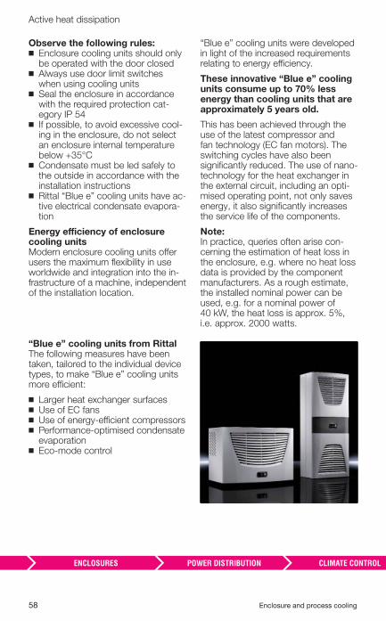
Energy effi ciency of enclosure cooling unitsModern enclosure cooling units off er users the maximum fl exibility in use worldwide and integration into the in-frastructure of a machine, independent of the installation location.
“Blue e” cooling units were developed in light of the increased requirements relating to energy effi ciency.
These innovative “Blue e” cooling units consume up to 70% less energy than cooling units that are approximately 5 years old.
This has been achieved through the use of the latest compressor and fan technology (EC fan motors). The switching cycles have also been signifi cantly reduced. The use of nano-technology for the heat exchanger in the external circuit, including an opti-mised operating point, not only saves energy, it also signifi cantly increases the service life of the components.
Note:In practice, queries often arise con-cerning the estimation of heat loss in the enclosure, e.g. where no heat loss data is provided by the component manufacturers. As a rough estimate, the installed nominal power can be used, e.g. for a nominal power of 40 kW, the heat loss is approx. 5%, i.e. approx. 2000 watts.
“Blue e” cooling units from Rittal The following measures have been taken, tailored to the individual device types, to make “Blue e” cooling units more effi cient:
◾ Larger heat exchanger surfaces ◾ Use of EC fans ◾ Use of energy-effi cient compressors ◾ Performance-optimised condensate evaporation
◾ Eco-mode control
Enclosure and process cooling 59
Active heat dissipation
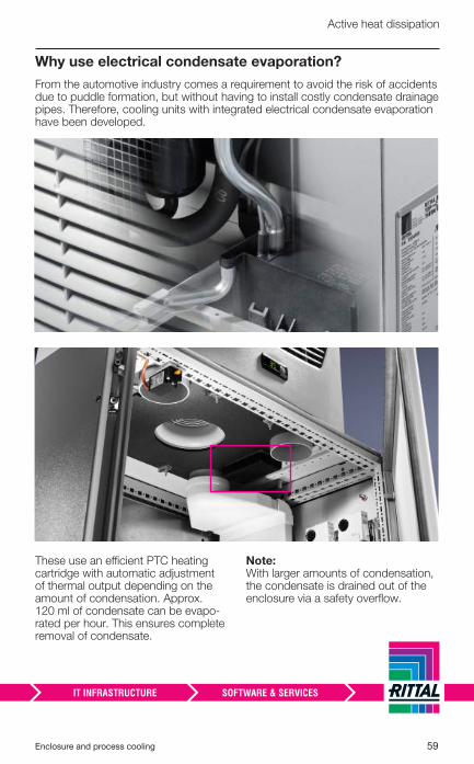
Why use electrical condensate evaporation?
From the automotive industry comes a requirement to avoid the risk of accidents due to puddle formation, but without having to install costly condensate drainage pipes. Therefore, cooling units with integrated electrical condensate evaporation have been developed.
These use an effi cient PTC heating cartridge with automatic adjustment of thermal output depending on the amount of condensation. Approx. 120 ml of condensate can be evapo-rated per hour. This ensures complete removal of condensate.
Note:With larger amounts of condensation, the condensate is drained out of the enclosure via a safety overfl ow.
60 Enclosure and process cooling
Active heat dissipation
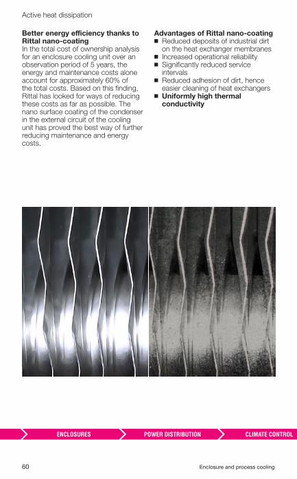
Better energy effi ciency thanks to Rittal nano-coatingIn the total cost of ownership analysis for an enclosure cooling unit over an observation period of 5 years, the energy and maintenance costs alone account for approximately 60% of the total costs. Based on this fi nding, Rittal has looked for ways of reducing these costs as far as possible. The nano surface coating of the condenser in the external circuit of the cooling unit has proved the best way of further reducing maintenance and energy costs.
Advantages of Rittal nano-coating ◾ Reduced deposits of industrial dirt on the heat exchanger membranes
◾ Increased operational reliability ◾ Signifi cantly reduced service intervals
◾ Reduced adhesion of dirt, hence easier cleaning of heat exchangers
◾ Uniformly high thermal conductivity
Enclosure and process cooling 61
Active heat dissipation
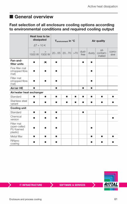
■ General overview
Fast selection of all enclosure cooling options according to environmental conditions and required cooling output
Heat loss to be
dissipated
ΔT = 10 K
Tenvironment in °C Air quality
< 1500 W
> 1500 W
20...55 20...70 >70dust-free
dustyoil-
contam-inated
corro-sive
Fan-and-
fi lter units ◾ (◾) ◾ ◾ ◾
Fine fi lter mat (chopped fi bre mat)
◾ ◾ ◾ ◾
Filter mat (chopped fi bre mat)
◾ ◾ ◾ ◾
Air/air HE ◾ ◾ ◾ ◾
Air/water heat exchanger
Standard ◾ ◾ ◾ ◾ ◾ ◾ ◾ ◾ ◾
Stainless steel variant
◾ ◾ ◾ ◾ ◾ ◾ ◾ ◾ ◾
Cooling unit
Standard ◾ ◾ ◾ ◾
Chemical version
◾ ◾ ◾ ◾
Filter mat (open-celled PU foamed plastic)
◾ ◾ ◾ ◾
Metal fi lter ◾ ◾ ◾ ◾ ◾ ◾
RiNano coating
◾ ◾ ◾ ◾ ◾ ◾
62 Enclosure and process cooling
Active heat dissipation
■ Design and calculation of climate control solutions using Therm software
Rittal fi rst made its Therm software for calculating and selecting climate control components available to cus-tomers as long ago as 1992. Today, software version 6.1 takes care of the entire laborious calculation process. A simple user interface guides the user to the appropriate, correctly dimen-sioned climate control components. All calculations are based on the requirements of IEC/TR 60 890 AMD 1/02.95 and DIN EN 14 511-2:2011.
Confi guration of all climate control components can be carried out with this software, which includes a con-fi gurator for recooling systems.
Another advantage of this software is the direct link to the EPLAN Cabinet planning software. By placing the necessary electrical components on the mounting plate, the heat losses are calculated and transmitted to the Therm software, which eventually calculates and specifi es the correct climate control components.
An important point is that these calcu-lations can be made available to the end customer as and when needed in the form of detailed documentation.
This software saves the planner a great deal of time and eff ort in design-ing the climate control solution.
Enclosure and process cooling 63
Active heat dissipation
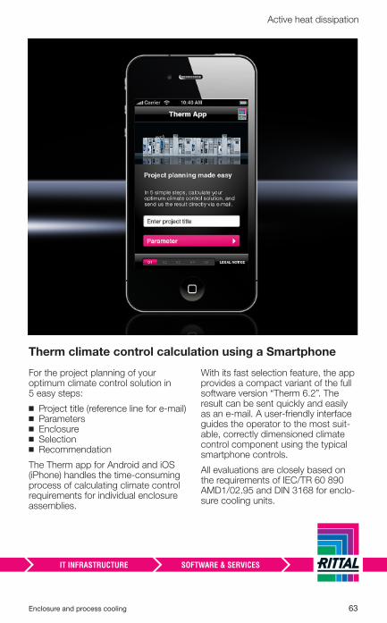
Therm climate control calculation using a Smartphone
For the project planning of your optimum climate control solution in 5 easy steps:
◾ Project title (reference line for e-mail) ◾ Parameters ◾ Enclosure ◾ Selection ◾ Recommendation
The Therm app for Android and iOS (iPhone) handles the time-consuming process of calculating climate control requirements for individual enclosure assemblies.
With its fast selection feature, the app provides a compact variant of the full software version “Therm 6.2”. The result can be sent quickly and easily as an e-mail. A user-friendly interface guides the operator to the most suit-able, correctly dimensioned climate control component using the typical smartphone controls.
All evaluations are closely based on the requirements of IEC/TR 60 890 AMD1/02.95 and DIN 3168 for enclo-sure cooling units.
64 Enclosure and process cooling
Enclosure and process cooling 65
Tips for project planning and operation
Useful and important tips for project planning and operation ....................................................................... 66◾ Correct enclosure construction and heat dissipation ............................... 66
◾ The external circuit – clear spaces ............................................................ 68
◾ Innovative air routing in the internal circuit ................................................ 69
◾ Air duct system.......................................................................................... 69
Maintenance ....................................................................... 71◾ Use of fi lter mats ....................................................................................... 72
◾ Outside air fi lter ......................................................................................... 73
66 Enclosure and process cooling
Useful tips for project planning
■ Useful and important tips for project planning and operation
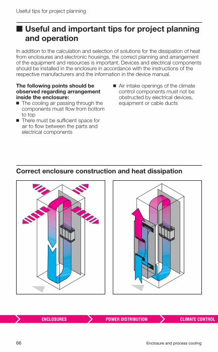
In addition to the calculation and selection of solutions for the dissipation of heat from enclosures and electronic housings, the correct planning and arrangement of the equipment and resources is important. Devices and electrical components should be installed in the enclosure in accordance with the instructions of the respective manufacturers and the information in the device manual.
The following points should be observed regarding arrangement inside the enclosure: ◾ The cooling air passing through the components must fl ow from bottom to top
◾ There must be suffi cient space for air to fl ow between the parts and electrical components
◾ Air intake openings of the climate control components must not be obstructed by electrical devices, equipment or cable ducts
Correct enclosure construction and heat dissipation
Enclosure and process cooling 67
Useful tips for project planning
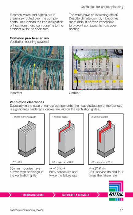
Electrical wires and cables are in-creasingly routed over the compo-nents. This inhibits the free dissipation of heat from these components to the ambient air in the enclosure.
The wires have an insulating eff ect. Despite climate control, it becomes more diffi cult or even impossible to prevent components from over-heating.
Ventilation clearancesEspecially in the case of narrow components, the heat dissipation of the devices is signifi cantly hindered if cables are laid on the ventilation grilles.
50 mm modules have 4 rows with openings in the ventilation grille
→ +10 K → 50% service life and twice the failure rate
→ +20 K → 25% service life and four times the failure rate
ΔT = 0 K
Project planning guide
ΔT = approx. +10 K
1 sensor cable
ΔT = approx. +20 K
2 sensor cables
Common practical errors Ventilation opening covered
Incorrect Correct
68 Enclosure and process cooling
Useful tips for project planning
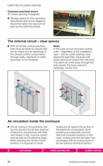
The external circuit – clear spaces
◾ With all climate control solutions, care must be taken to ensure that the air intake and air discharge of the climate control components through walls, machines or other structures is not hindered.
Note: In the case of roof-mounted cooling units – regardless of the installation type – one air outlet opening must al ways be kept free, because with these devices air enters from the front. The warm air is led away through the side panels, the back wall and, optionally, via the roof.
Air circulation inside the enclosure
◾ The air routing in the enclosure, tak-ing into account the air fl ow direction of electronic components with their own blower or fan, must be consid-ered as early as the planning stage. When planning the climate control solution, it is important to avoid
routing the air against the air fl ow of the electronic components. Such problems are especially common with roof-mounted solutions. In this case, cooling units and air/water heat exchangers with air routing ducts of-fer the optimum technical solution.
Common practical errors Air intake opening misaligned
◾ Storage space for the necessary documents and circuit diagrams should be taken into account as early as the planning phase.
Enclosure and process cooling 69
Useful tips for project planning
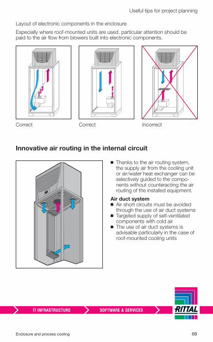
Layout of electronic components in the enclosure
Especially where roof-mounted units are used, particular attention should be paid to the air fl ow from blowers built into electronic components.
Correct Correct Incorrect
◾ Thanks to the air routing system, the supply air from the cooling unit or air/water heat exchanger can be selectively guided to the compo-nents without counteracting the air routing of the installed equipment.
Air duct system ◾ Air short circuits must be avoided through the use of air duct systems
◾ Targeted supply of self-ventilated components with cold air
◾ The use of air duct systems is advisable particularly in the case of roof-mounted cooling units
Innovative air routing in the internal circuit
70 Enclosure and process cooling
Useful tips for project planning
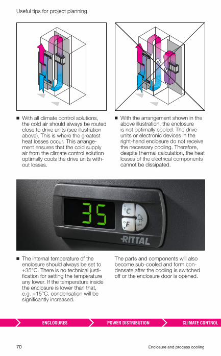
◾ With all climate control solutions, the cold air should always be routed close to drive units (see illustration above). This is where the greatest heat losses occur. This arrange-ment ensures that the cold supply air from the climate control solution optimally cools the drive units with-out losses.
◾ With the arrangement shown in the above illustration, the enclosure is not optimally cooled. The drive units or electronic devices in the right-hand enclosure do not receive the necessary cooling. Therefore, despite thermal calculation, the heat losses of the electrical components cannot be dissipated.
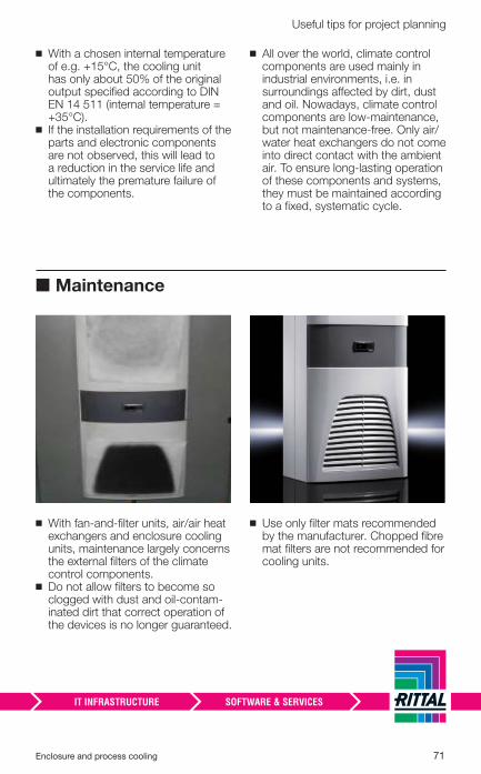
◾ The internal temperature of the enclosure should always be set to +35°C. There is no technical justi-fi cation for setting the temperature any lower. If the temperature inside the enclosure is lower than that, e.g. +15°C, condensation will be signifi cantly increased.
The parts and components will also become sub-cooled and form con-densate after the cooling is switched off or the enclosure door is opened.
Enclosure and process cooling 71
Useful tips for project planning
◾ With a chosen internal temperature of e.g. +15°C, the cooling unit has only about 50% of the original output specifi ed according to DIN EN 14 511 (internal temperature = +35°C).
◾ If the installation requirements of the parts and electronic components are not observed, this will lead to a reduction in the service life and ultimately the premature failure of the components.
◾ All over the world, climate control components are used mainly in industrial environments, i.e. in surroundings aff ected by dirt, dust and oil. Nowadays, climate control components are low-maintenance, but not maintenance-free. Only air/water heat exchangers do not come into direct contact with the ambient air. To ensure long-lasting operation of these components and systems, they must be maintained according to a fi xed, systematic cycle.
■ Maintenance
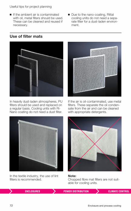
◾ With fan-and-fi lter units, air/air heat exchangers and enclosure cooling units, maintenance largely concerns the external fi lters of the climate control components.
◾ Do not allow fi lters to become so clogged with dust and oil-contam-inated dirt that correct operation of the devices is no longer guaranteed.
◾ Use only fi lter mats recommended by the manufacturer. Chopped fi bre mat fi lters are not recommended for cooling units.
72 Enclosure and process cooling
Useful tips for project planning
Use of fi lter mats
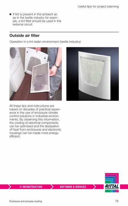
In heavily dust-laden atmospheres, PU fi lters should be used and replaced on a regular basis. Cooling units with Ri-Nano coating do not need a dust fi lter.
In the textile industry, the use of lint fi lters is recommended.
If the air is oil-contaminated, use metal fi lters. These separate the oil conden-sate from the air and can be cleaned with appropriate detergents.
Note:Chopped fi bre mat fi lters are not suit-able for cooling units.
◾ If the ambient air is contaminated with oil, metal fi lters should be used. These can be cleaned and reused if necessary.
◾ Due to the nano-coating, Rittal cooling units do not need a sepa-rate fi lter for a dust-laden environ-ment.
Enclosure and process cooling 73
Useful tips for project planning
Outside air fi lter
Operation in a lint-laden environment (textile industry)
All these tips and instructions are based on decades of practical experi-ence in the use of enclosure climate control solutions in industrial environ-ments. By observing this information, the cooling of electrical components can be optimised and the dissipation of heat from enclosures and electronic housings can be made more energy-effi cient.
◾ If lint is present in the ambient air, as in the textile industry for exam-ple, a lint fi lter should be used in the external circuit.
74 Enclosure and process cooling
Enclosure and process cooling 75
Machine and process cooling
What is machine and process cooling? ........................... 76◾ Applications of recooling systems/chillers ................................................ 78
◾ The modular recooler/chiller ...................................................................... 80
IT cooling
Recooling systems for IT climate control ........................ 81
Summary ............................................................................. 88
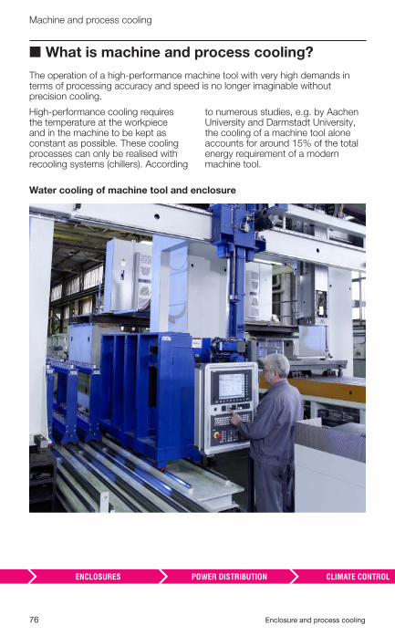
76 Enclosure and process cooling
Machine and process cooling
■ What is machine and process cooling?
The operation of a high-performance machine tool with very high demands in terms of processing accuracy and speed is no longer imaginable without precision cooling.
High-performance cooling requires the temperature at the workpiece and in the machine to be kept as constant as possible. These cooling processes can only be realised with recooling systems (chillers). According
to numerous studies, e.g. by Aachen University and Darmstadt University, the cooling of a machine tool alone accounts for around 15% of the total energy requirement of a modern machine tool.
Water cooling of machine tool and enclosure
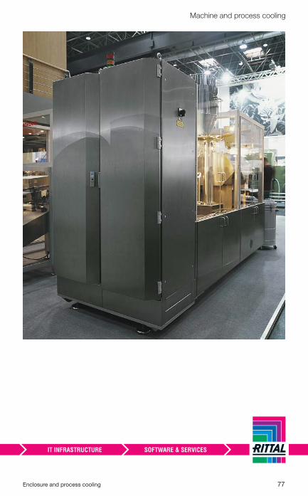
Enclosure and process cooling 77
Machine and process cooling
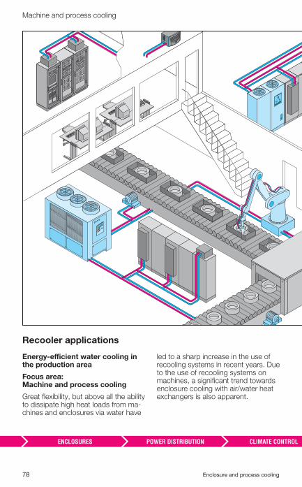
78 Enclosure and process cooling
Machine and process cooling
Recooler applications
Energy-effi cient water cooling in the production area
Focus area: Machine and process cooling
Great fl exibility, but above all the ability to dissipate high heat loads from ma-chines and enclosures via water have
led to a sharp increase in the use of recooling systems in recent years. Due to the use of recooling systems on machines, a signifi cant trend towards enclosure cooling with air/water heat exchangers is also apparent.
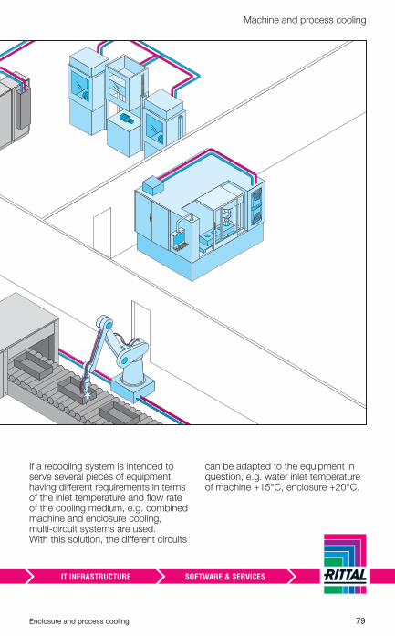
Enclosure and process cooling 79
Machine and process cooling
If a recooling system is intended to serve several pieces of equipment having diff erent requirements in terms of the inlet temperature and fl ow rate of the cooling medium, e.g. combined machine and enclosure cooling, multi-circuit systems are used. With this solution, the diff erent circuits
can be adapted to the equipment in question, e.g. water inlet temperature of machine +15°C, enclosure +20°C.
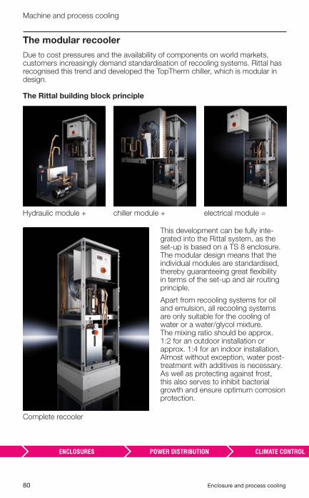
80 Enclosure and process cooling
Machine and process cooling
Complete recooler
Hydraulic module + chiller module + electrical module =
The modular recooler
Due to cost pressures and the availability of components on world markets, customers increasingly demand standardisation of recooling systems. Rittal has recognised this trend and developed the TopTherm chiller, which is modular in design.
The Rittal building block principle
This development can be fully inte-grated into the Rittal system, as the set-up is based on a TS 8 enclosure. The modular design means that the individual modules are standardised, thereby guaranteeing great fl exibility in terms of the set-up and air routing principle.
Apart from recooling systems for oil and emulsion, all recooling systems are only suitable for the cooling of water or a water/glycol mixture. The mixing ratio should be approx. 1:2 for an outdoor installation or approx. 1:4 for an indoor installation. Almost without exception, water post-treatment with additives is necessary. As well as protecting against frost, this also serves to inhibit bacterial growth and ensure optimum corrosion protection.
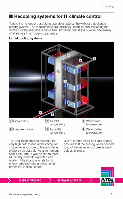
Enclosure and process cooling 81
IT cooling
■ Recooling systems for IT climate control
Today, it is no longer possible to operate a data centre without a dedicated cooling system. The requirements are: effi ciency, reliability and availability for 99.99% of the year. At the same time, however, heat is the number one enemy of all servers in a modern data centre.
Liquid cooling systems
The goal therefore is to dissipate the very high heat losses of the computer in a server enclosure to the outside as effi ciently as possible. As a competent specialist, Rittal is well placed to meet all the requirements expected of a modern infrastructure in relation to energy effi ciency and environmental protection in data centres.
Use of a Rittal chiller for liquid cooling ensures that the cooling water needed to cool the server enclosures is avail-able at all times.
1 Server rack
2 Heat exchanger
3 Air inlet temperature
4 Air outlet temperature
5 Water inlet temperature
6 Water outlet temperature
– � 1– � 3
– � 4
– � 2
– � 5– � 6
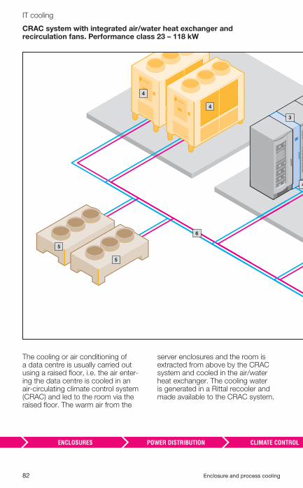
82 Enclosure and process cooling
IT cooling
CRAC system with integrated air/water heat exchanger and recirculation fans. Performance class 23 – 118 kW
The cooling or air conditioning of a data centre is usually carried out using a raised fl oor, i.e. the air enter-ing the data centre is cooled in an air-circulating climate control system (CRAC) and led to the room via the raised fl oor. The warm air from the
server enclosures and the room is extracted from above by the CRAC system and cooled in the air/water heat exchanger. The cooling water is generated in a Rittal recooler and made available to the CRAC system.
– � 5
– � 4
– � 5
– � 6
– � 3
– � 4
– � 4
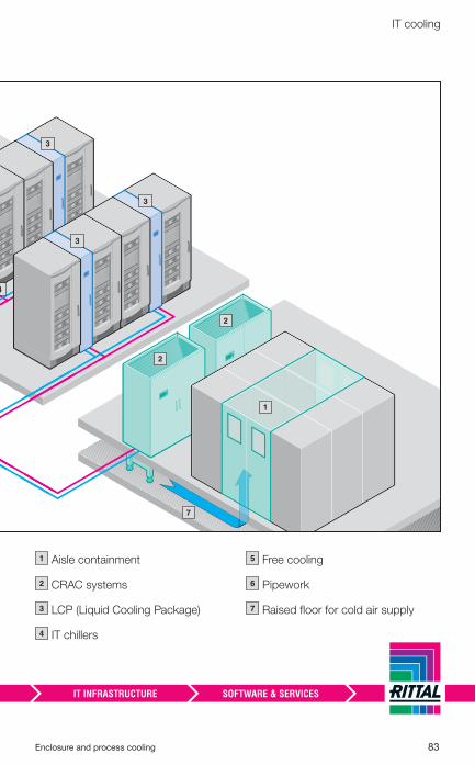
Enclosure and process cooling 83
IT cooling
1 Aisle containment
2 CRAC systems
3 LCP (Liquid Cooling Package)
4 IT chillers
5 Free cooling
6 Pipework
7 Raised fl oor for cold air supply
– � 7
– � 3
4
– � 1
– � 3
– � 2
– � 2
– � 3
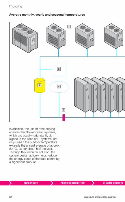
84 Enclosure and process cooling
IT cooling
Average monthly, yearly and seasonal temperatures
In addition, the use of “free cooling” ensures that the recooling systems, which are usually redundantly de-signed in the case of IT systems, are only used if the outdoor temperature exceeds the annual average of approx. 8.4°C, i.e. for about half the year. Through this technical solution, the system design actively helps reduce the energy costs of the data centre by a signifi cant amount.
– � 3
– � 2
– � 4
– � 5
– � 1
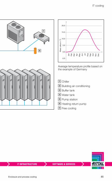
Enclosure and process cooling 85
IT cooling
0.0
-5.0
Jan
Mean v
alu
e in °
C
Feb
Mar
Ap
r
May
Ju
n
Ju
l
Au
g
Sep
Oct
No
v
Dec
5.0
10.0
15.0
20.0
1 Chiller
2 Building air conditioning
3 Buff er tank
4 Water tank
5 Pump station
6 Heating return pump
7 Free cooling
– � 6
– � 7
Average temperature profi le based on the example of Germany
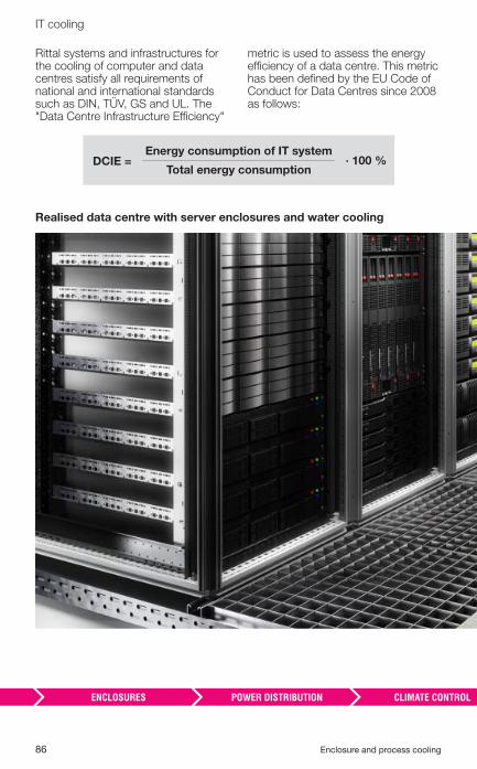
86 Enclosure and process cooling
IT cooling
Rittal systems and infrastructures for the cooling of computer and data centres satisfy all requirements of national and international standards such as DIN, TÜV, GS and UL. The "Data Centre Infrastructure Effi ciency"
metric is used to assess the energy effi ciency of a data centre. This metric has been defi ned by the EU Code of Conduct for Data Centres since 2008 as follows:
Realised data centre with server enclosures and water cooling
Energy consumption of IT system
Total energy consumption· 100 % DCIE =
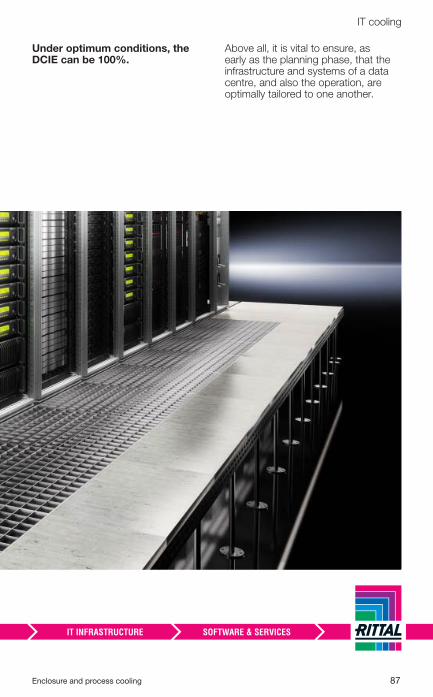
Enclosure and process cooling 87
IT cooling
Under optimum conditions, the DCIE can be 100%.
Above all, it is vital to ensure, as early as the planning phase, that the infrastructure and systems of a data centre, and also the operation, are optimally tailored to one another.
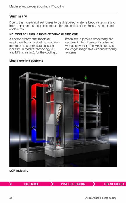
88 Enclosure and process cooling
Machine and process cooling / IT cooling
Summary
Due to the increasing heat losses to be dissipated, water is becoming more and more important as a cooling medium for the cooling of machines, systems and enclosures.
No other solution is more effective or efficient!
A fl exible system that meets all requirements for dissipating heat from machines and enclosures used in industry, in medical technology (CT and MRI scanning), for the cooling of
machines in plastics processing and systems in the chemical industry, as well as servers in IT environments, is no longer imaginable without recooling systems.
Liquid cooling systems
LCP industry
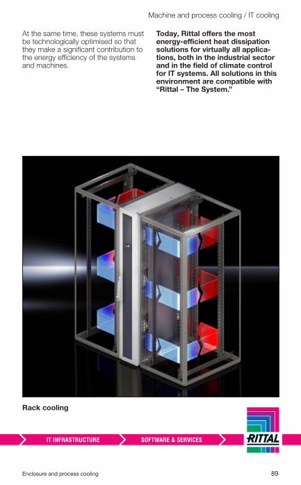
Enclosure and process cooling 89
Machine and process cooling / IT cooling
At the same time, these systems must be technologically optimised so that they make a signifi cant contribution to the energy effi ciency of the systems and machines.
Today, Rittal off ers the most energy-effi cient heat dissipation solutions for virtually all applica-tions, both in the industrial sector and in the fi eld of climate control for IT systems. All solutions in this environment are compatible with “Rittal – The System.”
Rack cooling
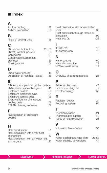
90 Enclosure and process cooling
■ Index
AAir fl ow cooling 22Arrhenius equation 20
B“Blue e” cooling units 58
CClimate control, active 26, 53Climate control, passive 26Convection 21Condensate evaporation, electrical 59Cooling circuit 54
DDirect water cooling 46Dissipation of high heat losses 48
EEffi ciency comparison, cooling units – chillers with heat exchangers 46Enclosure heaters 28Enclosure installation type 24Enclosure surface area 25Energy effi ciency of enclosure cooling units 58EPLAN planning software 62
FFast selection of enclosure cooling 57
HHeat conduction 21Heat dissipation with air/air heat exchangers 37Heat dissipation with air/water heat exchangers 42
Heat dissipation with fan-and-fi lter units 33Heat dissipation through forced air circulation 92Heat loss �v 23
IIEC 60 529 18IP classifi cation 18
NNano-coating 60Natural convection 22NEMA classifi cation 19
OOverview of cooling methods 26
PPeltier cooling unit 40ProOzon cooling unit 9PTC technology 59
RRadiation power 24Recooling system 64
TThermal radiation 21Thermoelectric cooling 40 Types of heat dissipation 21
VVolumetric fl ow of a fan 35
WWater-cooled mounting plate 26, 50Water-cooling, advantages 44
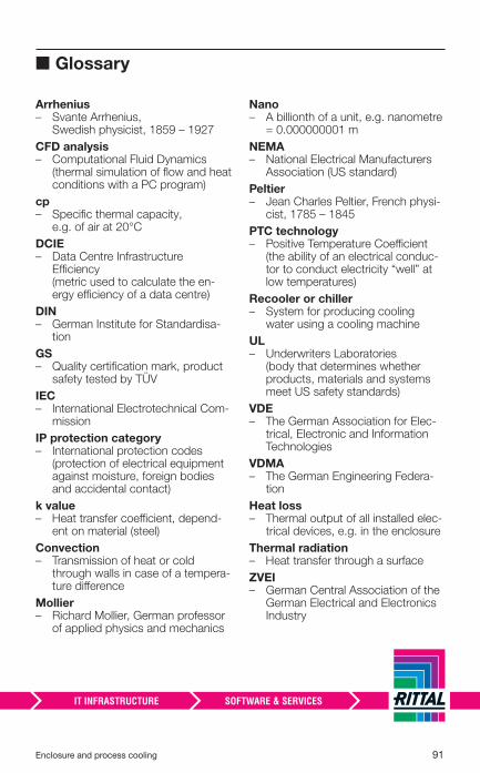
Enclosure and process cooling 91
■ Glossary
Arrhenius – � Svante Arrhenius,
Swedish physicist, 1859 – 1927
CFD analysis – � Computational Fluid Dynamics
(thermal simulation of fl ow and heat conditions with a PC program)
cp – � Specifi c thermal capacity,
e.g. of air at 20°C
DCIE – � Data Centre Infrastructure
Effi ciency (metric used to calculate the en-ergy effi ciency of a data centre)
DIN– � German Institute for Standardisa-
tion
GS – � Quality certifi cation mark, product
safety tested by TÜV
IEC – � International Electrotechnical Com-
mission
IP protection category– � International protection codes
(protection of electrical equipment against moisture, foreign bodies and accidental contact)
k value – � Heat transfer coeffi cient, depend-
ent on material (steel)
Convection – � Transmission of heat or cold
through walls in case of a tempera-ture diff erence
Mollier – � Richard Mollier, German professor
of applied physics and mechanics
Nano – � A billionth of a unit, e.g. nanometre
= 0.000000001 m
NEMA– � National Electrical Manufacturers
Association (US standard)
Peltier – � Jean Charles Peltier, French physi-
cist, 1785 – 1845
PTC technology – � Positive Temperature Coeffi cient
(the ability of an electrical conduc-tor to conduct electricity “well” at low temperatures)
Recooler or chiller – � System for producing cooling
water using a cooling machine
UL – � Underwriters Laboratories
(body that determines whether products, materials and systems meet US safety standards)
VDE – � The German Association for Elec-
trical, Electronic and Information Technologies
VDMA – � The German Engineering Federa-
tion
Heat loss – � Thermal output of all installed elec-
trical devices, e.g. in the enclosure
Thermal radiation – � Heat transfer through a surface
ZVEI – � German Central Association of the
German Electrical and Electronics Industry
92 Enclosure and process cooling
■ Bibliography
Bliesner, Jürgen: Wichtige Installationshinweise beim Schaltschrankauf-bau [Important installation instructions for enclosure design], Siemens AG, 2007.
Rittal GmbH & Co. KG: Praxis-Tipps zur Schaltschrank-Klimatisierung und Maschinenkühlung [Practical tips for enclosure climate control and machine cooling], Rittal GmbH & Co. KG, 2004.
Rittal GmbH & Co. KG: Rittal SK – System-Klimatisierung [Rittal SK – System climate control], Rittal GmbH & Co. KG, 2006.
Siemens AG: Schaltschrankintegration, SINAMICS S120 Booksize/SIMODRIVE – Systemhandbuch 09/2007 [Enclosure integration, SINAMICS S120 Book-size/SIMODRIVE – System manual 09/2007], Siemens AG, 2007.
Styppa, Heinrich: Klimatisierung für Gehäuse, Maschinen und Anlagen – Grundlagen, Komponenten, Anwendungen [Air-conditioning for enclosures, machines and plants – Fundamentals, Components, Applications]. Die Bibliothek der Technik, vol. 284, sv corporate media, 2005.
Schneider, Ralf, et al.: Projektierungshandbuch Schaltschrank-Entwärmung [Project Planning Manual: Enclosure Heat Dissipation], 2nd edition, December 2011, Süddeutscher Verlag onpact GmbH, 81677 Munich.
Enclosure and process cooling 93
94 Enclosure and process cooling
Enclosure and process cooling 95
TÜV-tested output to DIN EN 14 511:2012-01
An important aspect when stating the cooling output of an enclosure
cooling unit is the measurement of output according to the relevant European
standard (EN).
This European standard sets out the conditions for testing the cooling
output of air conditioning units, liquid cooling packages (recooling systems)
and heat pumps that use air, water or brine as a thermal transfer medium,
with electrical compressors for space heating and/or cooling. These output
measurements independently carried out by TÜV give customers the assur-
ance that their enclosure cooling unit achieves the required cooling output
and complies with the current energy effi ciency ratio (EER), i.e. delivers
optimum energy effi ciency.
Rittal “Blue e” cooling units have been tested according to this standard in
the output range from 300 to 4000 watts and bear the TÜV test mark.
Except cooling units with Atex authorisation for Zone 22 and NEMA 4X.
Previously published:
12013
22013
32013
Standard-compliant switchgear
and controlgear production Application of IEC 61439
Enclosure and process cooling
Technical aspects of enclosures
11.2
013/3
3A
7
RITTAL GmbH & Co. KG
Postfach 1662 · D-35726 Herborn · Germany
Phone + 49(0)2772 505-0 · Fax + 49(0)2772 505-2319
E-mail: [email protected] · www.rittal.com
Enclosures
Power Distribution
Climate Control
IT Infrastructure
Software & Services