Enclosure 20 to TN E-28034, Scavuzzo, R.J., Lam, P.C., Gau ...
86
Enclosure 20 to TN E-28034 Scavuzzo, R. J., Lam, P. C., Gau, J. S., "Buckling Tests of Fusion Welded Composite Stainless Steel Aluminum Plates," Dept. of Mechanical Engineering, The University of Akron, May, 1990 (associated with RAI 2-7 and RAI 2-13)
Transcript of Enclosure 20 to TN E-28034, Scavuzzo, R.J., Lam, P.C., Gau ...

Enclosure 20 to TN E-28034
Scavuzzo, R. J., Lam, P. C., Gau, J. S., "Buckling Tests of FusionWelded Composite Stainless Steel Aluminum Plates," Dept. ofMechanical Engineering, The University of Akron, May, 1990
(associated with RAI 2-7 and RAI 2-13)
Test Report
Buckling Tests of Fusion Welded Composite Stainless Steel
* Aluminum Plates
May 1990
R. J. Scavuzzo
P. C. Lam
J. S. Gau
Department of Mechanical Engineering
The University of Akron
Akron, Ohio 4.43.25-3903
This work was sponsored by UST&D Inc. and waswitnessed under UST&D!s QA program

CONTENTS
PAGE
INTRODUCTION 1
TEST DESCRIPTION & RESULTS 1-7
TEST CONCLUSIONS 7
TABLES#1#2
Load vs. Deflection Date - Specimens Al, B1 & ClLoad vs. Deflection at Temp. Data - Specimens Dl, A2, B2 & C2
FIGURES#1 Sketches of Plate Test Specimens A, B, C & D#1A Buckling of the Steel Plates of Specimen Al Due to Initial Load
(Photo)#2 Specimen Being Mounted on Baldwin Compression Machine (Photo)#3 Specimen Being Mounted on Tinius Olsen Universal Test Machine
(Photo)#4 Specimen Being Aligned (Photo)#5 Electric Chromalox Heaters Being Installed on Specimen (Photo)#6 Controller for Electric Chromalox Heaters#7 Insulation of Specimen (Photo)#8 Installation of LVDT (Photo)#9 Compression Machine Load Indicator (Photo)#10 Initial Reading of the LVDT (Photo)#11 Initial Reading of the Thermocouple (Photo)#12 Room Temperature Buckling Testing of Composite Panel Al Using
Baldwin Compression Machine#13 Room Temperature Buckling Testing of Composite Panel Al Using
Tinius Olsen Universal Test Machine#14 Room Temperature Buckling Testing of Composite Panel B1 Using
Tinius Olsen Universal Test Machine (Graph)#15 Room Temperature Buckling Testing of Composite Panel Cl Using
Tinius Olden Universal Test Machine (Graph)#16 Panel Al After Buckling (Photo)#17 Panel B1 After Buckling (Photo)#18 Panel Al, B1 and Cl After Buckling (Photo)#19 High Temperature Buckling Testing of Composite Panel D1 Using
Baldwin Compression Machine (Graph)#20 High Temperature Buckling Testing of Composite Panel A2 Using
Baldwin Compression Machine (Graph)#21 High Temperature Buckling Testing of Composite Panel B2 Using
Baldwin Compression Machine#22 High Temperature Buckling Testing of Composite Panel C2 Using
Baldwin Compression Machine
APPENDIX A - Calibration of Equipment Certification
APPENDIX B - Test Certifications
APPENDIX C - Materials Documentation

1
Test Report
Introduction
The objective of the test was to load composite plate
specimens in compression to determine the buckling load and
post buckling behavior. Tests were conducted at room
temperature and at elevated temperatures (z400*F at-the corner
of the specimen). Different fusion weld configurations were
tested.
Testing was conducted in two phases. In Phase I three
specimen. were tested at room temperature. The test results are
listed in Table 1. In-the secondphase, Phase II, tests were
conducted at elevated ....temperatures such that the minimum
temperature was 40:GF. This minimum temperature occurred at
the corner of the specimen. At the center, temperatures were
approximately 500,F and .varied with each specimen. Details are
in Table 2.
Test Specimen Description
Three 24" long, 8.05" high and 0.72"' thick composite plate
specimens with four, six and eight fusion welds respectively
were tested. Sketches of the plate specimens are provided on
Figure 1.
The plates are composed of two inner 6061-T6 aluminum
plates, each 0.25" thick and two outside 304 SS plates, each
0.11" thick. The steel plates were wider than the aluminum
plates by about a 1/161" on both sides. Thus, the loading was

2
first applied to the outer steel plate until they were
compressed to the width of the aluminum plates. Then the
compressive load was .shared by both the aluminum and steel
plates. This initial load cause buckling of the steel plates
(Figure 1A), prior to buckling of the aluminum.
Calibration:
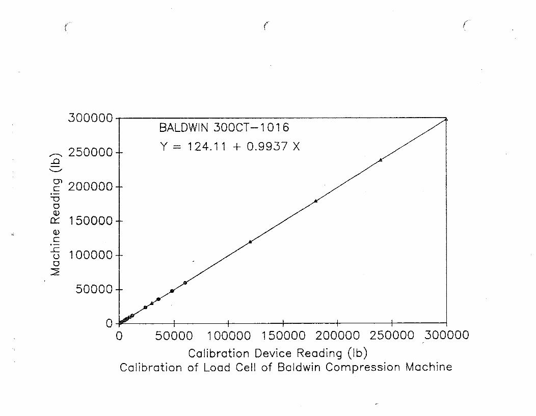
Prior to any testing on the Baldwin Compression Tester, the
machine was calibrated by C&M Calibration Service, 230 Haymond
Dr. P.O. Box 149, Gibsonia, Pa. 15044 on April 13, 1990.
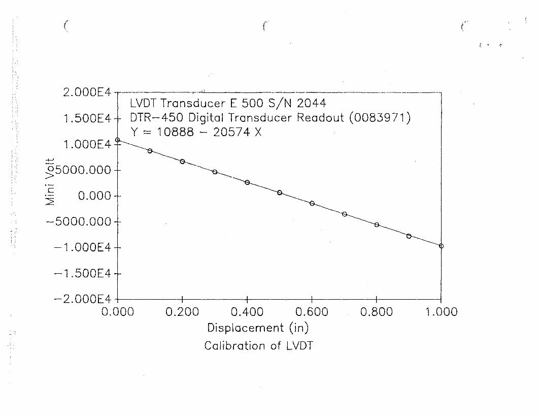
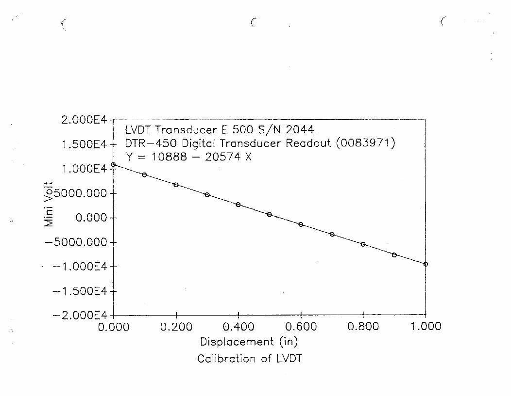
The LVDT (linear variable displacement transformer) was
also calibrated prior to use as indicated in Appendix A. A
LVDT calibration instrument was used for this purpose. This
device consists of a fixture to hold the LVDT and a micrometer
at one end. The voltage read-out versus deflections is
obtained. The micrometer was checked against standard gage
blocks. The calibration data is provided in Appendix A.
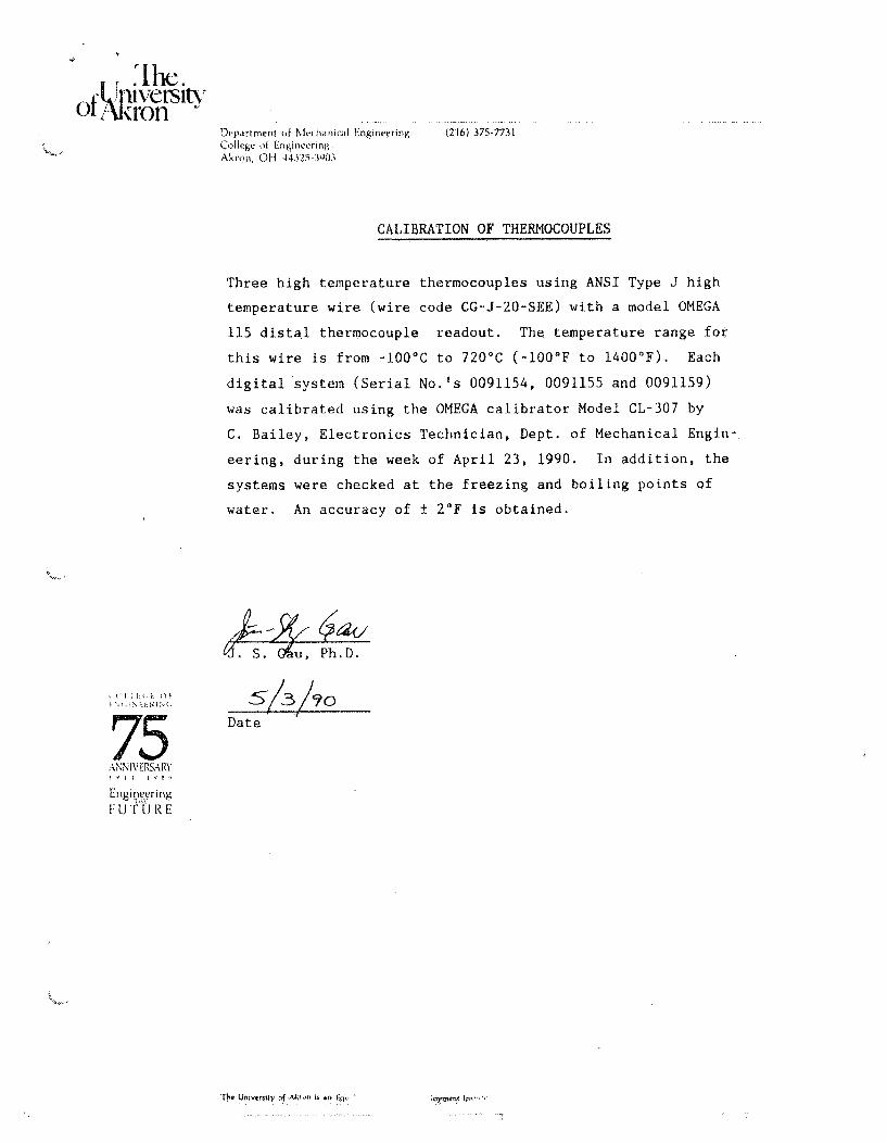
For the high temperature work, the three thermocouples and
digital read out devices were calibrated using newly purchasedelectronic devices specifically for these instruments. In
addition, the thermocouples and read-out devices were checked
against the boiling point and freezing point of water. These
results are also provided in Appendix A.
Phase I Room Temperature TestinQ:r
The first specimen with 4 fusion welds spaced in pairs at
12" apart was tested in a 300,000 lb Baldwin compression test

3
machine (Figure.2) at University of Akron. However, this
machine did not have enough force capacity to buckle the
specimen. This preloaded specimen (Specimen Al) and two other
specimens with 6 and 8 welds respectively (Specimens Bi and CI)
were tested in a 1.2 million pound Tinius Olsen Universal Test
Machine (Figure 3) at the Pittsburgh. Testing Laboratory. All
the tests were conducted at room temperature.
Specimen Al
The top of the fixture was mounted to the Baldwin
compression test machine with a bolt at its center. The bottom
fixture was braced with two wood planks to prevent lateral
slipping if buckling should be initiated. Care was taken to
align the specimen vertically (Figure 4). A brass circular bar
on both the top and bottom support plates provided a pin type
support. A grove was milled into each. circular brass bar to
support the plate test specimen in the lateral directions
(Figure 4).
A compressed load was applied in 20,000 Ibs increments from
0 to 280,000 lbs. The maximum load was 290,000 lbs. The last
load increment was 10,000 lbs. The load rate was applied at
0.2"/min. Lateral and top support plate deflections were
measured with dial indicators and recorded at the 20,000 lb
increments.
Specimens Al, BI & Cl: Preloaded Four, Six, Eight Fusion Welds
Additional tests were run to buckle the room temperature

4
specimens: Al, Bi, and C1. These. tests were run at thePittsburgh Testing Laboratory to obtain a higher test capacity.
The test of specimen 1A., originally loaded on the Baldwin
Compression Machine, was retested on. the 1.2 million pound
Tinius Olsen compression machine. The top of the fixture was
mounted to the Tinius Olsen test machine with a single bolt.
The bottom fixture was braced with two steel plates to prevent
lateral slipping once the specimen buckled. Other specimens
were supported ::in the same manner as. Specimen 1A of the
previous test. A compressed load was applied with a head
travel rate of 0.2',/min. Load and deflections were recorded.
with a load cell and LVDT. Load-Deflection curves were
automatically plotted during the tests.
Phase II Elevated Temperature Testing.:
In this phase of testi ng, all tests were conducted on the
Baldwin Compression-Machine at the Civil Engineering
Laboratory, University of Akron. Electric Chromalox heaters
and controller (Figures 5 & 6) were used to heat each specimen
while installed the Baldwin Compression Tester. Each specimen
was wrapped in a blanket insulator after being installed in the
Tester (Figure 7). In order to reduce heat conduction to the
top of the Tester, there was a gap between the top edge of the
specimen and brass bar. A fiber glass sheet was used to reduce
heat conduction to the bottom platen of the Tester.
In the first specimen (Specimen Dl with 12 welds), two
Chro-malox heaters were used to elevate the temperature.

5
Approximately. 4 hours, were needed to reach a minimum
temperature of 400F. ..The last three6specimens A2, 12 and C2
were heated with four Chromalox heaters and one controller
(Figure 5).
Two thermocouples were used to measure the temperature of
the specimen: one was located at :the center and one at the
outer edge of the-speimen. The edge thermocouple was located
1" above the bottom support and: 1/2" from the side. The
difference between these temperature measurements, when the
minimum edge temperature-reached 400-°F, was about 100°F. The
third thermocouple monitored the pl.at.en temperature of the test
machine, ,as a safety precaution against overheating.
Test. Procedure Phase II
1. Install the test panel on compression test machine.2. Install the strip heaters on the test panel.
3. Install t hermostat sensor bulb in the end of the panel.
4. Cover the panel with insulating blankets.
5. Attach thermocouples at the center and edge of the panel..
6. Set the thermostat for 550 9 F and heat the test panel until
corner thermocouplep: reading is above 4000F.
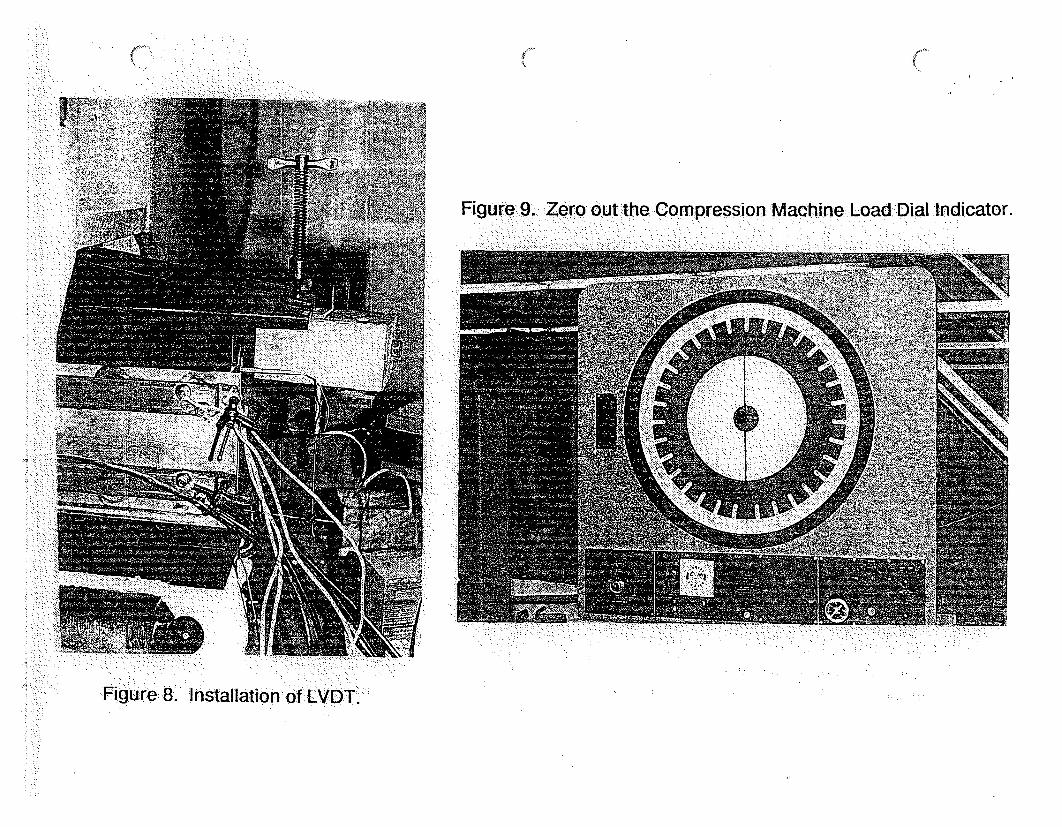
7. Install the LVDT between the load patterns (Figure 8).
8. Zero out the compression machine load dial indicator
(Figure 9)
9. Record initial reading of LVDT and Thermocouples (Figure 1.0
and 11).
10. Start loading the test coupon and fixture at a rate of

6
0.2."/mi~n. Continue loading and .recording load and vertical
deflection: data: for every 20,-000lb increments.
ii. Mark.and record the highest load obtained prior to load
decreasing. Continue the 0.2,./min loading rate until the
load fallsof f to 50%. of the maximum value obtained. Then
stop the. loading.
12. Record the final LVDT, load, and temperature readings
obtained at the stop position.
13. Unload..the ýýcompression machine and remove the test panel.
Repeat setup. and steps 1-13 for. each test panel.
Results
Phaseg I Room. Temperature Tests:
For the: first test on specimen Al, containing four fusion
welds. and using. the :Baldwin. compression test machine, measureddeflections: were..plottedon Figure 12 and recorded on Table: ...
The specimen did not buckle at a load 290,000 lbs at room.
temperature (75.F). However, because .the width of the two 304
SS plates were. larger than. the 0.25"1: aluminum plates, there was
some bulging of the outer. cladding (see. Figure 1A).
Using. the Tinius Olsen compression test machine, measured
load-deflection curves were. plotted. and are shown in Figures 13
to 15 for the four, six and eight fusion welds specimens.
Maximum loads .for the tested specimens- are listed in Table 1.
Specimens buckled. at an average load of about 330,000 lb.
From these test results, the failure:. mode indicated that the
two aluminum, plates and one steel. plate buckled in one

7
direction while the. other steel plate buckled in the opposite
direction, (Figure .117. and 18).
Only one fusion weld failed during all of the testing
(specimen Bl), and this was attributed to very large lateral
deflections well1 past the buckling point. For this case,
vertical deflections were :off scale (Figure 14)ý and exceeded
0.45". Photographs of the buckleidill: specimens are shown on
Figures 16, 17 and 18. Post buckling loads are listed in
Table 1.
Phase II Elevated Temperature Tests:
Deflection versus load results. are shown on Figures 19 to
22. Numerical resu.lts. are- tabulated in Table 2. Temperature
measurements at the start of the test are also listed in Table
2. The average maximum load for *specimens A2, B2 and C2 is
260,300 pounds: which is 79% of the r6oom temperature value.
Conclusions.
From the test results the following i•conclusions can be made:
1. The same buckling failure mode was observed in allspecimens.
2. Except for the weld -pattern: 5establishing the bucklingspan, the fusiion: weld. patternsi tested: had no effects. onbuckling load at either temperature.
3. Weld failure did not occur in.any specimen in which theedge deflection was less than 0.45",.
4. By increasing the temperature to a minimum value of4 00 0 F. et buhe buch. kling. load is erduced to 79% of the roomtemperature value.
5. At, both temperatures:, substantial post bucklingstrength can.be expecte. :This is shown by the_ load-deflec.ti .on: cu rves ..as thde .graduali s!opetý after reachingthe buc k i..ng load., in :Figures. 13,714 & 15.

Table 1: :Load vs. Deflec n for Panel Buckling Test.,
Load Disp(1;).. Disp(2). : Disp.(3)(lb)ý (in* 10-3)'(in* 10-3) (...* 1 0-3)
20000 .:63 20. 35:40000 7 :79,: 44: :.o6760000 :. 89 .:.. '64: 100::80000 98......79 39"
100000 1.06 . 0 16:::0
.80;o , 0 •6 :, .0..3o " .1
1.20000 113 140." 187:140000 120 170 2081160000 17 195, . 22,9180000 ý134 218 250:200000 1I40 '. ý238 i271
22000 146. 258, 292ý240000 153 275: 309.:260000 159ý 292 329:-280000 1:65, 308, .347:ý2900010 168 36l 357
Specimen Al (1) B1 C.Load Disp 4W Disp6W.. Disp W.
(Ib) (i* 10-3) (irl 10-3) (.•* 10-3)
00 0 0.200o:: 4.0 4 5040000 45. 42: 54:60000 . 46.: '43.. 56:80000" ... 47 57:
1 00000 48 : -458..120000 49 46 59140000 4:49 47 61.160000 49 48 6.2,::180000. .49: 50:. 63.200000 49. 56' 64:.
220049 58 6.5.:240000 50 60 .66::.260000 :51 : 61 68:280000 51 :62 *69300000 52,. ::862 72:
,..320000 ,iŽ 52 63 765
-340000-- 54 ________
320000 60 70 76-300000 66 80 83 1:280000 73 92 -90 1260000 82. :104 . 97
240095 11:4 106:2 20000 9110 .1..: 1 :105:n20000 1:32 1424 121::1'80000. 160 1!: 162::160000.. 175. .. 1 :76- " .: ._
1.40000.:. 256. 21::21:,.12000.0 .. : 270p
l~o100000i " ____ 380 4._" __
(1) Retest. o Specimen Al.:Note: :Load Pace =.0.2"/min
All:Deflections in Lateral Direction
1,333~
(1) Lateral Deflection
(2) Transverse Deflection of the Right Panel
(3) Transverse Deflection .of the Left Panel
Note:. Load Pace =0.211/min
U of Akron BaldwinCompression:Machine.Specimen.Al,. (4: Fusi.on Weld: Panel):
:Pitt sburgh Testing Lab Tinius :Olsen Universa• Test MNlac•.h e.Specimens Al:..B1 and Cl.(4, ý6 and 8 Fusion.Welds. Panel)

Table 2: Load vs Deflection for Elevated TemperaturePanel Buckling Test.:Using BaldwinCompression Test Machine
SPecimenDD1 " SpecimenA2 Specimen B2 Specimen C2• Load .Disp : Tern/C TemtE Dis T Te isp Tern/C Tern/E Disp Ter/C Tern/E
(Ib) (in). (F) (F) (in) " () (F) (in) (F) (F) (in) (F) (F)
0 0 485 405 0.000000 629 408" 0.00000 504. 410 ý0.000009 425 403.
2o0o000 0.0110o85 0, 0.036308 0.045154 0.052989: ....40000 0.01 43047_ 0.037912 _! _ 0.047973, 0.054933:l:60000 0.015362 - 0.038982 04 :0 9042 ___, 0.05668380000 0.015654 0.039614 0.050306 . 0.058384
i00000 0015799. 0.040051 0.051327 __ I_ 0,05989 1i:200000 0.0158979 0..... .. 0.040294 0.051813 ...... 0.0609192 _ _
1:40000 0.015945 __ 0.040488 0.052007. 0.061786 __
160000 0. o 15994 _•._ 0.040634 :0.052056 0.062613180000 0. 015994 0.040683D '_ .052105: 0,063342:%200o000 .o016042:. .:04040731 0..0521205 0. ".:063876 1220000 0.016091 ,:0.040780 ":0., 0.052105 .... .064362: , ._
:240000 0.01614.0. 0.0140780: ___0.052153- t__ __ .649 __ _
:253000 0.01W6334.. _ 0.040780m : 1 0.052199 0.065338 ._ "
.261•500 0.016460: _. __ .. 06.052229: 0065626: 5 •
266000:: 0.016528.11 ===___=_= _____=== 0.052245. : _ _, ."...267250 ____t __ ____ __1_ 0.05225:: . '2400,00 _____.. 0.045751 .... -0.0571I64. _____ 0.066060:
220000 __" :1 0.053399 :.0.060771:i:: 010.6466411.200000 0,0610416 0.064378 0.066868:1.80000 0,___ O 068694 0.067986 0.067271:
160000 .0,0763.4111 ." _,. . :0.071593 :,__" 0.067675:.1:40000 0.083989 :,0.075200 0.068079 _
132500. 0.0-086857 0.0 76553.: 405. 285 0.068230:'
13.1.5001_: 0.087239: _0,068251 415 2691... i25000 "____ _ ....... . _ 0.089725: 629 5 246 __... ' " _"... . '" " " I " • .
Note: Load :Pace = 0.24/min

i-s; I0r,
Ty,=ý I QL
~47- 0f4
4,
A / 7~7/~( -
00
~,,'T/l-- /
Figure 1. Sketches of Plate Test Specimens A, B, C and D.

Figure lA. Buckling of the Steel Plates of the Specimen Al due to Initial Load.

.Figure 2. Specimen being:Mounted on Badwin Compression Machine.• ~ ~ ~ ~ ~ ~ ~ o n e • ..... .o ... ....:Ba ... :: . . . .. ..... .. V.a• .....
Figure3. Specimen beinglMounted on Tinius Qlsen U niversal:Test Machine.

Figure 4. Specimen being Aligned.
\.
Figure 5. Electric Chromalox Heaters being lnstalled on: Specimen.

Figure 7. Insulation of Specimen.
ilgure.6. Controller for Electric AChrm l t.!:: .. : ,. ." .a: . .
Srk
Figure 9. Zero.out the .Compression Machine: Load Dial.Indicator.
Figure: 8. Installation ofLVDT.

FigU re. 10..•. Initial Reading of the: LVDT.
Figure 1. linitial Reading of the Thermocouple.
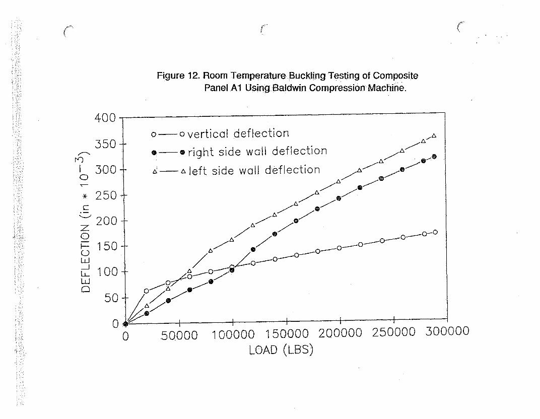
Figure 12. Room Temperature Buckling Testing of CompositePanel.Al Using Baldwin Compression Machine.
400
350
7'O
0
b-
C)
z0
I--
:w_.
300
250
200
150
100
50
00 50000 1 0000 0 150000 200000 250000 300000
LOAD (LBWS)

Figure 13. Room Temperature Buckling Testing of Composite:Panel Al Using Tinius Olsen Universal.Test Machine.
Plý ...
iilillilili
I CI Ill~-e9Q• ~ I
1 4 1
I Iii
I IIiU)
.0
V
0-J
Deflection (in * 5E-3)

Figure 14. Room Temperature Buckling Testing of CompositePanel B1 Using Tinius Olsen Universal Test Machine.
~/~7~ZV
JC~T~2
C',
0
A A A
Iii~I I
Ii
•tiiii
RA
lee-, erw-, I, II
F 1
Al hAil !IAj /
Deflection (in * 5E-3)

Figure 15. Room TemperatureBUckling, Testing of Composite
Panel.c1 Using Tinius&Olsen Universal Test Machine.
!Ho
1. I . • • . .. .. • • ,1 I H I
CIS.0
i 1
i! l I}' ,1 I IIII •i'
! 1 ' ' I.,[ [ I i ; .i . ! : :
I': .I
' . t I .!i" :
V I Ii. 0O . .- . - ,- • ...• ! -....'..... ....: ' • .. ..'- "/ . ,:: ' .... •" • r ,"" ..• ' . ! ~ i i
Deflection (in *5E-3)

Figure 16. Panel Al :after Buckling.
Figure 17. Panel BI after Buckling.,

Figur -18. Panel.Al:, Bi and.C after:Bucklingc.

Figure 19. High Temperature Buckling Testing of CompositePanel Dl Using Baldwin Compression Machine.
2580000
0Q
0-il
240000
200000:-
160000-
12000:0-
80.000-
40000-
0
0
0
0
K I00
!
Ut
0.000 0.020I .i
0.040 0.060Deflection (in)
0.080 0.100
Deflection :as Measured by LVDT model :E 5:00 S/N 2044

Figure 20. High Temperature Buckling Testing: of'CompositePanel e : AUsing Baldwin Cmp:ression Machine.
28.0000
240000
2000:00
0-JýO,
1 60000
120000-
80000
40000
00.000 0.020 0.040. 0.060 0.080 0
Deflection (in)Deflection as Measured by LVDT model E 500 S/N 2044
.100

Figure 21. High Temperature Buckling Testing of Composite
Panel B2 Using Baldwin Compression: Machine.
2800:00
240000-
200000-
160000-
0-A
0
00
0
0I
0
I.0I
0I0/,,,
120000+n
80000-
40000+
tI' I !
C
I *d)~~'-.1 1 I I ,I
).000 0.020 0.040 0. 060 0.080Defl .ection (in)
Deflection as Measured by LVDT model E 500 S/N
0.100
2044

Figure 22. High Temperature Buckling Testing of CompositePanel C2 Using Baldwin Compression Machine.
0.0-J
280000-
240000-
200000-
160000-
120000-
80000-
40000-
I
0
10
01
0I
0I
00
0I
0/
0/0/
0/
n A.-
C-' , - i I
).000 0.02:0 0.040 0.060Deflection (in)
Deflection as Measured by LVDT model
0.080 0.100
E 500 S/N 2044

Appendix A

... .hc.----------
Department or ,Mechanical Engineering 2-16) 375-7731College of Engineering:Akron, OH 44325-3903
CALIBRATION OF THERMOCOUPLES
Three high temperature thermocouples using ANSI Type J high
temperature wire (wire code CG-J-20-SEE) with a model OMEGA
115 distal thermocouple readout. The temperature range for
this wire is from -100 0 C to 720 0 C (-1000F to 1400'F). Each
digital system (Serial No.'s 0091154, 0091155 and 0091159)
was calibrated using the OMEGA calibrator Model CL-307 by
C. Bailey, Electronics Technician, Dept. of Mechanical Engin-
eering, during the week of April 23, 1990. In addition, the
systems were checked at the freezing and boiling points of
water. An accuracy of t 2°F is obtained.
J. (. ~u, Ph.D.
F IDate
EngineeringfUTURE
The Uniwiv nL t.Akrn is An Equal Eduat-on And Enmp;-mrent Insiut~n-

700-Calibration of 0091159 at the Freezing and
D600iBoiling Point of WaterY - 1.239 + 0.98944 X
5004-
4-00
-_300
0
o 200E :
100-
0 100 200 300 400 500 600 700
Temperature of Water (0 F)
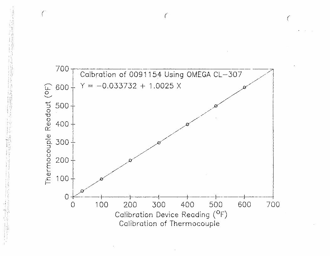
700 Calbration of 0091154 Using OMEGA CL-307
y Y -0.053732 + 1.0025 XJ
f
7'-7
0
0
C-)
E
500-
400-
300-
200
100
7,
,07-
7,7-
LL
KK 7
x
or
0 !
0I0 J I I ,I
200 300 400 500Calibration Device Reading (OF)
Calibration of Thermocouple
600 700

700ICalbration of 0091155 at Freezing and Boiling Point,.,-
2600 of Water-Y 0.25902 + 0.98944 X
n 500- .-
®400
-00u000
1~-00 -
0
o200 100
Tca 000 I---H ]-----i --- h- -
0 10O0 200 300 400 500 600 700Temperature of Water (0 F)

700
cr_
Li)0-
:30
0
0
600-
500-
400-
300-
200-
100-
Calbration of 0091155 Using OMEGA CL-307
Y = -0.63457 + 1.0044 X
J 7
;-7
7A
7
70
0
00 100 200 300 400 500 600 700
Calibration Device Reading (OF)Calibration of Thermocouple

700 lCalbration of 0091159 at Freezing and Boiling Point
2•EL 600 of Water0nY= -0.93941 + 0.995 X
4o -
0
o 4001
• -3001
00o 200-E-1 100% +
0 -/ t- +--t----I-----t-
0 100 200 3O0 400 500 600 700Temperature of Water (OF)

700-7 Calbration of 0091159 Using OMEGA CL-307
C" 600 Y = -1.0431 + 1.0049 X0
S5.000
Qo400
0-n300--0
0 200EI-Q)-C 100I--
0 I .lz0 100 200 300 400 50.0 600 700
Calibration Device Reading (OF)Calibration of Thermocouple

lihe.i'f •lvers1tv _ _ _ __
Department of Mechanirc. Engineering 216) 375-7731.College o( EngineerinpAkron, OH 44325-3903
CALIBRATION OF THE BALDWIN COMPRESSION MACHINE
The compression test machine was calibrated on April 13, 1990-
prior to the start of the test series by C&M Collins Calibration
Service.
Attached is a plot of the calibration data for the compression
machine and the data taken by C&M Collins Calibration Service.
VJ. S. Ga.4, Ph.D.
Date
75ANNIVERSARY
Engineering
FUTURE
The. UrnivrrsfY. of Akron is -0 E~ual Edo-tion and Enmploymantn 1115tuItion

~0
c
00
0
C)
300000
250000
200000
150000
100000
50000
00 50000 100000 150000 200000 250000 300000
Calibration Device Reading (Qb)Calibration of Load Cell of Baldwin Compression Machine

C&M COLLINS CALIBRATION SERVIC.€ETHIS IS TO CERTIFY that the following dlescri bed testing machine h:as been calibrated by C&M CALI-BRATION and the loading range(s) shown below found: to be within a maximum tolerance of
/, %.
MACHINE __ _ _ _ _ _ _ _ _ _ _ __,_ _TYPE. o ,-r
LOCATION (... i ; V e-S-,' o /r ,, CAPACITY 30coo' 6/&r
i-ir',Lo,4- ,..A;& 32.S SERIALNO, 3COCT -.. oi .
DATE O:F VERIFICATION A '. .. 3. /f?9oMethod of verification and below recorded data it ln accordance with A S.T.M. E-4 cc-. . The testing device(s) used forthis calibration have certifications traceable to-.the National Institute of Standards Technology.
Machine Readings .2 Pounds.C. Newtops.0 Kilograms Readings temperature corrected for .71., 'F.MACHINF CALISRA71ON DEVICE MACHINE ERROR C.0
READING READING t ." N01
S C2 I )2a. 4-+(.? . ,
_ _.o _,. ,t? .- / _ z
7209 7 4-j.o . ' 1
16.00 0___ __ o -SIo S.3 ?
,:_____ IJ909 .'-l .:7667[ 6000 -7, ,1?OO0 3e.•77- + .e3I? .If O .o 0•~ - o .
3. .o , ii ' 3,Y 5
6oIooo ] - 4I o .- 7 5
MACHINE . CALIBRATION DEVICE mADNINE ERROR D.READING READING / ,'t. "4 NO.
?....... U P .7 go. . ... _= 00oo0 ee _ _.__/ . t/
'2 Y...0 o 00 0e 3 s-o K 0•9. ./"
?O:Oo 9. 9 •Te 9 q•o /. .70 3
L ."' . _._ __._.' ' +.1.
_________"HF' ....
CALIBRATION APPARATUS - Morehouse.Proving RIngs, Staln.sense load cells & Troemner Dead Weights. Verificationstraceable to .the National Instilute.of".Standards Technoloay; in accordance with A.S.T.M. latest speciftcations.C. .. SEIRIAL NO. LO.0ADINiG RANGE CALIB. NATIONAL INSTITUTE OF STANDARDS TECHNOLOGY LA: NO. TEMP.CODE CLASSAVALUE DATE OFC.D.
*2 3 7-( 63?2-10h f6 !;?7 k 97 731_7_Y_ý
2 2R2t to ii l&oO 5t. 9# -?5'-ty S J-7- 0/ 2 1- -7 7___3 ' _.. .'_ .' _ ,. .. " _"'" '_ _.. ._.. . . . ._ _ __" '_ _'_ _'_ _'" '_ . .. _m _ _ _ _ ___
. , . i . , , . ,. . . . ,, ,
MACHINE RANGE LOADING:RANGE
/ -- o6 o ('c 18o - 160oo lW
30.. - 00o 1 h
O - ho0 t•!, 20.i -3..oof /•
Primary Load Indicating Device___.T - L,- e,..r• .....
C & M COLLINS CALIBRATION SERVICE230 Haymont Dr., Box 149, Gibsonia, PA 15044
(412). 443-7631
ý- 7-- rZýBy:.1 SERVICE ENGINEER)
%Yilnessed By.:

She.j" l]versitv
Department of Mechanical Engineering ý216) 375-7731College of EngineeringAkron. OH 44325-3903
CALIBRATION OF THE LVDT
The LVDT calibrator is a micrometer device on a fixture. Both
the calibration device and LVDT, model E 500 S/N 2044, were
calibrated using the model DJR 450 digital transducer readout.
(a) Calibration Device
The micrometer of the calibration device was calibrated
on May 2, 1990, using Johansson Gage Blocks. Attached is
a plot of this calibration, The accuracy is t 0.001".
(b) Calibration of the LVDT
The LVDT was calibrated during the week of April 16, using
the calibration device. A plot of the calibration is
attached. Measurements are within t 0.010.
oi I I" ý0I ;, N rt:i I,(,
75 JS u, Ph.D.
ANNIVERSARY
Engineering 6 C)ETU.T-U RE Date
Th. Un-vnnty o0 Akron is an Equal Eduction and Employent lnsotfution

'~ ~,
0
Q)
L.Q
4-,ci)E0
1.000-
0.900-
0.800-
0.700-
0.600-
0.500-
0.400-
0.300-
0.200-
0.100-
Calbration of Micrometer (No 262) onLVDT Transducer E 500 S/N 2044Using JOHANSSON GAGE BLOCK 1 ASerial No 10008 lJ
Y = -0.0001 2236 + 0.99943 X
K
- I --- !
7-
A 7 -
n nnr)
0.000--- , 1
I I I
0.200 0.400 0,600Thickness of Gage Block (in)
Calibration of Micrometer
0.800 1.000
2.000E4
1.500E4-
1.000E4'
05000.000-
C: 0.000-
-5000.000-
- 1 .000E4-
- 1.500E4-
LVDT Transducer E 500 S/N 2044DTR-450 Digital Transducer Readout (0083971)Y = 10888 - 20574 X
)
-2.000E4 I0.000
00.200 1 1
0.400 0.600Displacement (in)
Calibration of LVDT
00.800 1.000

APPENDIX B
TEST CERTIFICATION

# --us, L),
CERTIFICATE OF CONFORMANCE
THIS IS TO CERTIFY THAT THE LOAD TESTING OF THE STAINLESS STEEL/ALUMINUM
COMPOSITE PANEL WAS SATISFACTORILY PERFORMED IN ACCORDANCE WITH THE
REQUIREMENTS OF TRANSNUCLEAR SPECIFICATION E-11586 AND UST&D CONTRACT
SPECIFIC PROCEDURE CSP-89-011-1, Rev. 1.
UST&D QUALITY ASSU RA NCE MANAGER DAT 5 -7
UNIVERSITY OF AKRON REPRESENTATIVE DATE______
*SEE ATTATCHED INSPECTION SUMMARY REPORT FOR DEVIATIONS FROM
THE REFERENCED PROCEDURE.
J

IUST&D, )Ntuclem" lo'uct~cs
Inspection Summary ReportProject 89-011-1
The following composite panel load tests were conductedin accordance with QC procedure CSP-89-011-1 Rev. 1 with thefollowing exceptions:
1). Panels A-2, B-2 and C-2 were initially heated with4 heaters prior to test. A-2 had 2 heaters removed justprior to testing. The other 2 heaters were left installedduring the test. B-2, all 4 heaters were used and operatingduring the entire test. C-2, 4 heaters were installed duringthe entire test, however power was disconnected at the startof the test.
2). All test panels were heated to at least 4000 at thestart of the test. Thermostat was set at maximum setting toobtain at least 4000 at both the center and edge of testpanel. The temperature readings prior to testing at centerof panel varied from 4250 to 6290.
UST&D Quality Representative/QC Manager
Engineering Concurrence
UST& VP En eering
I 75 Butler StreetPittsburgh, PA 15223412-784-7225

LJST\ 1), --
F- ý 1; ",4; A"'ý 'ýc sýý *-'ý-' 'V ý"
COMPOSITE PANEL LOAD TEST DATA SHEET
START OF TEST DATA
a) TEMPERATURE
b) LOAD ________,
c) VERTICAL DEFLECTION
d) TEST PANEL ID# Ae) No. OF PANEL WELDS .
f) DATE & TIME o .• ,
AT MAXIMUM LOAD READING
a) TEMPERATURE .9'e',dJ"• z7os, deb ) LOAD . . .. . !2.,
c) VERTICAL DEFLECTION .o•07
END OF TEST (50% of mqx. od)
a) TEMPERATURE _ _ _ _ _ _ _ _ _ _ _ _ _ _ _ _
b) LOAD , .
c) VERTICAL DEFLECTION , _"_,._ _,,,
d) TIME ,o; ".
EQUIPMENT DATA
a) TYPE
b)
c)
MODEL No.
RANGE a!' ice, -ZcOA r - Oo I90 06F
47/3 ZT
-300 CT-- 01I
C0 0o 0, L&0.I4d) DATE CALIBRATED
e) CALIBRATED BY
University of Akron Test Operator
UST&D Test Supervisor (Engineer)
UST&D Quality Representative
Transnuclear Witness (if required) - _..._ _ __/_ _...... .
\1

High Temperature Buckling Testing of Composite Panel A2
280000
240000
200000-
160000-
120000-
"Q
0_j
0
0
/0
/
80000+
40000-
n I
C.J 7I a a
).000 0.020 0.040 0.060 0.080 0Deflection (in)
Deflection as Measured by LVDT model E 500 S/N 2044
,100

UST\I)\\~I~ A U
COMPOSITE PANEL LOAD TEST DATA SHEET Z,
START OF TEST DATA
a) TEMPERATURE 1 ,1fJq/ ~~;eb) LOAD __
c) VERTICAL DEFLECTION ,)d) TEST PANEL IDO 132-
e) No. OF PANEL WELDS
f) DATE & TIME 9 0
AT MAXIMUM LOAD READING
a) TEMPERATURE L/-,50.1JIe sij
b) LOAD ?6 7 2-5c.
C) VERTICAL DEFLECTION
ND OF TST (50% of max. oad)
a) TEMPERATURE _____ ____ ___d__11____ ____
b) LOAD 3 Z, 67..
c) VERTICAL DEFLECTION ,, 7 (76__ _........ . ....
cl) TIME
EQUIPMENT DATA
a)b)
d)e)
TYPE
MODEL No.RANGE
DATE CALIBRATED
CALIBRATED BY
D rf? Zria-m, 1/60, 6 0ý
0 10 ý o z390ý64* 1c) q C'Lr1 1-,Z.90 I
University of Akron Test Operator
UST&D Test Supervisor (Engineer)
UST&D Quality Representative
Transnuclear Witness (if required)
r• I I .. .~. ., .,. .i .. ... . ...

High Temperature Buckling Testing of Composite Panel B2
280000
240000
200000
0-j
160000t
120000'-
800001
40000--
0C).000 0.020 0.040 0.060 0.080 0
Deflection (in)Deflection as Measured by LVDT model E 500 S/N 2044
.100

r tiS'LX1) ~/. ~
'XV, A '!'-,"1-'V "4." 1ý"Xý 41
COMPOSITE PANEL LOAD TEST DATA SHEET
START OF TEST DATA
a) TEMPERATURE 2- Z5 7 l;'/e Ic 3 ,db) LOAD
c) VERTICAL DEFLECTION 0_
d) TEST PANEL ID# C Ze) No. OF PANEL WELDS
f) DATE & TIME 3 0
AT MAXIMUM LOAD READING
a) TEMPERATURE 7- 6 ,9
b) LOAD 2 '/ 5c0
C) VERTICAL DEFLECTION - .
END OF TEST (50% of max. load)
a) TEMPERATURE -3 32Z r.1;(/e 9 c9 c4L s*sde
b) LOAD
c) VERTICAL DEFLECTION 4'4 S Z 5/d) TIME '4.4"/- O,,N..E . .. .,,, .. .
EQUIPMENT DATA
a)
b)c)
d)
e)
TYPE -nay~~ n0- /MODEL No. ).•ri.5o,.S,,zO.M r, - 3_OC_-_1,6
RANGE o-,oi g " A,,1,, - - F- C43 1 0oo ..bs.DATE CALIBRATED -.. /1 1, . /goCALIBRATED BY p. 42i&Jo,, " CoI,.S
University of Akron Test Operator
UST&D Test Supervisor (Engineer)
UST&D Quality Representative ___..-._.....
Transnuclear Witness (if required)
\1

High Temperature Buckling Testing of Composite Panel C2
£2
00
-j
280000-
240000-
200000-
160000-
120000-
80000-
40000-
0.,0
I
0
0
0
00
/
0/
0
0$ .C).000 0.020 0.040 0.060
Deflection (in)Deflection as Measured by LVDT model
i
0.080 0.100
E 500 S/N 2044

1C.
Of r01,1[Departmecnt of N'1tc~han ical Enginee~ringC~ollege of EngineeringAkron, 01-1 4,1325-3903
(216) 375-7731
CALIBRATION OF THE BALDWIN COMPRESSION MACHINE
The compression test machine was calibrated on April 13, 1990
prior to the start of the test series by C&M Collins Calibration
Service.
Attached is a plot of the calibration data for the compression
machine and the data taken by C&M Collins Calibration Service.
Ge , Ph.D.
Date
'. 0 . LI (; 1 0 F1F N Cý I N EF h RF N t,
*\NNIVUSAI(Y
En)4ineerin).F Ui T Ui R E
The Univem~ity, of *Axron 4,a Fqu~ poyetI.looanft , nPloymvni Insmution
-Q
Q)a:V
C)C
300000
250000
200000
150000
100000
50000
00 50000 100000 150000 200000 250000 300000
Calibration Device Reading (Ib)Calibration of Load Cell of Baldwin Compression Machine

SSeport & (Tertificai e of erifiratiouC&M COLLINS CALIBRATION SERVICE
THIS IS TO CERTIFY that the following described testing machine has been calibrated by C&M CALI-* BRATION and the loading range(s) shown below found to be within a maximum tolerance of
/1 %.
MACHINE TYPE
LOCATION "/) ; V ej,^.r I' I L_' CAPACITY 30Oo00/4j
CA; o) SERIAL NO. 10oCT -,/o/,_(
DATE OF VERIFICATION .. pr,'l /3 ,'?90Method of verification and below recorded data Is In accordance with A.S.T.M. 2-4 8 .3. The testing device(s) used forthis calibration have certifications traceable to the National Institute of Standards Technology.
Machine Readings U] Pounds El Newtons 0 Kilograms Readings temperature corrected for 72. Y 'F.
MACHINE CALIBRATION DEVICE MACHINE ER OR C.0READING READING %NO
2iL ~ C/ 4- ,7
-7 0 0 _ -71____o 4-13.0 .j I
12 00 0 1 1 og -e- / .76 e
1.6000 e a .17 3
36oooo 3 y t - o .71 3
MACHINE CALIBRATION DEVICE MACHINE ERROR c..
READING READING q 6," . NO,
. C 000 to/?' /Y , 3
12 0000 //9_____
/8100o0 /71Žo5 f79 9 .' 3
00000 Z 9790 9 o??/ ,70 .
CALIBRATION APPARATUS - Morehouse Proving Rings, StaInsense load cells & Troemner Dead Weights. Verificationstraceable to the National Institute of Standards Technology, in accordance with A.S.T.M. latest specifications.,C.D. SERIAL NO. LOADING RANGE CALIB. NATIONAL INSTITUTE OF STANDARDS TECHNOLOGY LAB NO. TEMP.CODE CLASS AVALUE DATE OF CD,
1__ 3914!t'-6 612-IOA 16s !S-27-kY 7X 2'?! 1 Ž7 S 5 I?2 R o j?3?al •to S.T70Fr -// I1o? 1.-7 7e
3 ?'5lC?3 4Z I..rgo-o¢ ....g- S-?1-9 SIT7o0 // /o0, 2,,,7 7__1
4
5 __________ _______ ______
MACHINE RANGE LOADING RANGE
6 000o 161 (,,ooo -6ooov c r
0-~~ O?-d IotJo 1jk
Primary L.•ad Indicating Device
C & M COLLINS CALIBRATION SERVICE
230 Haymont Dr., Box 149, Gibsonia, PA 15044(412) 443-7631
By:(RENE(SERVICE ENGINEEFR)
W•tnessed
By:
Witnessed By:

o r L I 11VCrI.
, ~plrsit\
[)epartinent at o Med:)anical Engineering (216) 375-7731C.ollege o(f EngineeringAkron, OH 44325-3903
CALIBRATION OF THE LVDT
The LVDT calibrator is a micrometer device on a fixture. Both
the calibration device and LVDT, model E 500 S/N 2044, were
calibrated using the model DJR 450 digital transducer readout.
(a) Calibration Device
The micrometer of the calibration device was calibrated
on May 2, 1990, using Johansson Gage Blocks. Attached is
a plot of this calibration. The accuracy is ± 0.001".
(b) Calibration of the LVDT
The LVDT was calibrated during the week of April 16, using
the calibration device. A plot of the calibration is
attached. Measurements are within ± 0.010.
0;! N-b. S. au, Ph.D.ANNIVE RSA Y
Fngineering U R -DFUTURE Date
The Univonity 4' Akron i. an ' luction -a. Iinplovrnrt In51.titai

C:
0"0
E0
0)
1.000-
0.900-
0.800-
0.700-
0.600-
0.500-
0.400-
Calbration of Micrometer (No 2632']LD rasueLVDT Transducer E 500 S/N 2044Using JOHANSSON GAGE BLOCK 1 ASerial No 10008Y = -0.00012236 + 0.99943 X j-
I I I
flm
0.300 -
0.200-0.100-
n' n' t"•I t"•
0.000I I I
0.200 0.400 0.600Thickness of Gage Block (in)
Calibration of Micrometer
0.800 1.000
2.000E4
1.500E4
1.000E4
05000.000
LVDT Transducer E 500 S/N 2044DTR-450 Digital Transducer Readout (0083971)Y = 10888 - 20574 X
0.000
-5000.000-
-1.000E4 -
- 1.500E4+
-2.000E4 10.000
I ! Ii i -
0.200I i
0.400 0.600Displacement (in)
Calibration of LVDT
0.800 1.000
ro•
[)epartment of Mechacnical Engineering (216) 375-7731College of Engineering.Akron, OH 44325-3903
CALIBRATION OF THERMOCOUPLES
Three high temperature thermocouples using ANSI Type J high
temperature wire (wire code CG-J-20-SEE) with a model OMEGA
115 distal thermocouple readout. The temperature range for
this wire is from -100 0 C to 720 0 C (-100°F to 1400'F). Each
digital system (Serial No.'s 0091154, 0091155 and 0091159)
was calibrated using the OMEGA calibrator Model CL-307 by
C. Bailey, Electronics Technician, Dept. of Mechanical Engin-
eering, during the week of April 23, 1990. In addition, the
systems were checked at the freezing and boiling points of
water. An accuracy of t 2'F is obtained.
S. u, Ph.D.
75 Date
ANNI\ERSARY
Engineering
F U T U R E
Thv.Uniw~rfty of ~At, - iý anF, ioppene tno ;

7 0 0 i
Calbration of 0091154 Using OMEGA CL-307
2" 600± Y = -0.033732 + 1.0025 X
% 5100-j04-
400
'I)-3000020 200E Tci)
_ 100H1--
0 100 200 300 400 500 600 700
Calibration Device Reading (OF)Calibration of Thermocouple

700- 7 Calbration of 0091154 at Frezzing and Boiling PointL600-of Water
o Y =1.239 + 0.98944 X
500±0
400
-300000 200E
_c100F-
00 100 200 300 400 500 600 700
Temperature Of Water (OF)

7 0 0 Calbration of 0091155 at Frezzing and Boiling Point~-~ 6 ~jof Water
0 Ty = 0.23902 + 0.98944 X -
:3 5000
Q400
3-3000
0200E-
0
0 100 200 300 400 50 600 7600Temperature of Water (OF)

700 Calbration of 0091155 Using OMEGA CL-307
o600- Y =-0.63457 + 1.0044 X
o5004-0 0t
-0
02E
4.00I- 300-
0
0c 1001
0 100 200 300 400 500 600 700Calibration Device Reading (OF)
Calibration of Thermocouple

(.
700-,Calbration of 0091159 at Frezzing and Boiling Point
i 600o"of Water0 Y= -0.93941 + 0.995 X
4o-
D 400--
Q)~- 3000
o 200-7E
-c100 +
0 -- 4----------- I -I
0 100 200 300 400 500 600 700Temperature of Water (OF)

700 Calbration of 0091159 Using OMEGA CL-307
QL 600 Y = -1.0431 + 1 .0049 X0
5000
Q400
c,300:30
E
£100
0--
0 100 200 300 400 500 600 700Calibration Device Reading (OF)
Calibration of Thermocouple

APPENDIX C
MATERIALS DOCUMENTATION

1\cý
DOCUMENTATION CHBCKLI8T
CUSTOMERDOCUMENTS PAGE PAGE REVIEW & REMARKS
QTY. NO. RELEASE
DOCUMERNTATION CHECKLIST17.2 1 1
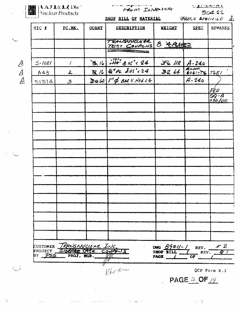
SHOP BILL OF MATERIALS 8.... ..8.3 1 2 __ __ __ _ _. . . ..___ __ _
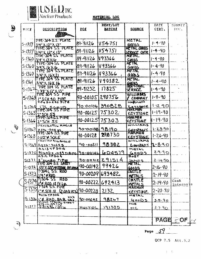
MATERIAL LOG8.1 3 3- 5
ýMATERIAL TEST REPORTS & 5 6-11CERTIFICATES OF CONFORMANCEWELD EXAMINATION RECORDS
10.5 12 12-13
DIMENSIONAL DATA RECORD 1 14
.FINAL INSPECTION CHECKLIST 1 1510.4
CUSTOMER P.O. NO. UST&D PART NO. PART DESCRIPTION QUANTITY4-Phase I
NA Drawing 89-011-1 CASK INTERNALS 4-Phase II
UST&D CERTIFIES'THAT THE LISTED WORK AND REQUIRED DOCUMENTS MEET THEREQUIREMENTS OF THE PROCUREMENT DOCUMENTS.
UST&D' QA/QC DATE
WORK WAS RELEASED ON SATISFACTORY COMPLETION OF INSPECTION AND REVIEWOF DOCUMENTATION.
CUSTOMER REPRESENTATIVE DATE
CUSTOMER TRANSNUCLEAR PROJECT UNIVERSITY OF AKRON
UST&D PROJECT NO. 89-011 SHIPMENT NO. ONE
form 17.2
PA E.W OfJ
L/iw/ ProductsF-dyI"O UTX)L ! * L,4 5c04 s _
A
H PC. HK , QUA DECITO "tI=d =Q1¢ RETMARKS
2-. -_7 :L ? " Ji....• S 0 ______
;24 46041
_______ /(~, ~ £ O • . .. _ _ _ _ _ _
-4--
. .. . . .. 3. i . . . . .j i .4.
- _ ___ ___ ___ ______ ___ 2
4 S S. p
4 9-9 9 .1 t
b 0 .0 S P I
S -~0 - S 6~~~W . 9*
-. . .. ..a. .'
USTOMER .. ... f .. ... i JDWG REV.ROJECT SHOP al LL REV. 07Y , PRoJ. NGR. PAI ._ OF .
V
QCP Form 8.3
PAGE OF .2L

v,--1ý UST& D
U. S. TOOL & DIE, INC.
MATERIAL LOG
FOR AqLUMINUMP.O0. Heat -Lot - Da te Submit
MIC # Description Numnber Batch # Source Cert. Doc.
A-J6 644 1 TroALUM 83-11S97 So7PNE .16_____31"y211 Z G)( G4 I pe 83 _ ________ _____PAN__Y
G0QI-T ;AUIM PL 8 3. 1 5 7 206 LG-
___7 L &3.1597 ?S-9 30 5F F[2-' SCA. 4A55)2D'O' FFe0-
F~ 2.8ALOM, . Q (qI-T(6 84i8. 84o:L6IOO7QO( R@N9104b3M[. i5
R-30 f -1 34--VZ 10-17-_4(oft I73 -(5q10qq'_ aI-G3 OCM~fNY
2_A;___ BAR4I/ as~-SS0 C rbMC2-7q 4IL i:?s-3-85
A-34 Wz"!-T4oALL 7'/'1$_DO 23 C1C ____ -B'UR CO
~-~' ~E3~3U14JJN ~V5 C of c CIPN -O
S2 z/'TK -Ss '"705C f C. 'WILLIA r__A .37 -87 _Z_1__C
_________________.8 q -o ,2 QM 'aS.A43 -:4 DI Hfi~,xq4 ______ ____TM_ /____ 5-(o'? nteaC
K
(Page
Form 8.1
PAGE 3 . F•_P

-. UST&DU. S. TOOL & DIE, INC.
MATERIAL LOG
P..O. Heat -Lot - Da te Submit
MIC # Description Number Batch #t Source Cert. Doc,
5-1010 ff7-~V~T 6'0-7O'W 272Z14\N HUB INC.214 -
_7__ -70 91Jk Iboq HUBIC in. -21-88
S-1012 I/2sX.IXL 67-70 q/ 17I1147W HUB INIC 2.8
S71013 iyZ?-Aq. lay,..q.16 87-70q/4 1.1 q 7 W I1UB INC. -.- 8 __
C,- It14 .)4 't~ 87-7Oq/ý' 2 7 V 19W HUB IN.C. 2- zl-n
T115 FO Y'iS17-10914 073 76W HUB )INC 22-5
S- /1 A'qj8XI 57-7OqIý 2Z31 5a HUB I NC. 2-29-688__
S40~ ~x?. '4 88 17752 ~70330 3
S-6Z5~-802-03 ICP(,597 HUB INC. 3--
S ~xiqZ1 06 88-O2-l 635S'qq R~YERSON 3-3-~88itra
S-!23 CHO L 88-802-42 75978 N
__ _ _ _ __ _ _ _8 -8012 ý 71 .9? /5 ~W c I . o
_____ j~31(~I-&J3 I/ COMPA~NY z
2-0.~56X843U7-70704 F7OV1 ___I 'E RL
10-8 ioz J f.7O .A e E ,a9-052-3 143/8 3
.S-130 ~s~ ~ ~OxL~ 87 -705Z~73 . q3lf8
______ ~~ 67TO23 13I 3-Ii.6e
~13Z',j0 x 8-6O203 9:2-0 1-10:5 INC. 3-I8-88______ __________ e 2JI1 3711915- _ _
~~~~ LtEI 855~ 04 .X~BO~ 888o2~ '5 ______ ___ ____
Form 8. 1 Page S-1oiPAU-~ L
,\'dvlt-t("I~t~lrdldsMlizin LOG
p t I I
m I cjý
-10
1/3 (~0
-LLBITQ ~QLHEAT/LOT
BRTCHLOATE.s: i.1T
5LlItM TI)()(,
L
T8--'"/°2(o V54-75"i fzpvhL1TYP- 3'arS S K f" _ q-9 12.4 ~V54051 i -4-o'-4- -C9
(-4-90":V4'VNIL I• C. , Bq-A IZ •12.4v 1 ,344 MWr"L- -. 4 * 4.L -,
&59q1-Tl,, V q3?:ho , i P .GcobS
1-4"-0I YIM Suto " P" LA I t"3/41! X, I (o)21 8c1_9112.1 V 33Ld. Go 1Iii,
a
.13 y TYFc 30 eSS Pt. 8T3/44 Y. •~ I L• ffi-qTI24 V q 0131 MCTALrfJul}kq. I- 4 -q1
3/A4)( l h6 -4 I. 4iIxlmra p . 4T' U04 S PLI-AT"r"4A"') 11." & Ull •q-7i,23. fl825 IUIJJLI rI¶L
7IR7iC I-_-,_TIC S4: C3 PIPEI S'cCW •r) PIFW qo-O oiosi Zq:fO757(,,
ILLIA I) .-- 4 .. ~
,c, % s~oA5ss pirisk, I&cn 9 0 -0010 6 5Yio0F -fý 1-az q90
_axajý. - . . . -
BTc.304 5h rpIP70 -OWZS I 7S30 Z'
MttImmV I-vv.c~oI 9. .rA mE •." lli
?"'~CH 5'~ qO-00512- 75.3 03 "uwrw NK~f YSMAI 1- UI-o
4)
(
5.P5. IPE qo-0012S- 134 8 1-,1/2`0. 5CA.. SCY "gN, - --
-3 _ aottk o 98 9•Z ý 2 a-1A'O-oo q IL It _K,_LI
!5 _ r1•. J s tr. .0-cOWr.., Z r (9.13'A _ -_-
1_!",s 44. Rd-00228 2132.0. 0EY348.. 2-20-0o
. •9•-oo0zAz 9&Z"T _Is-_ o
CaskInterna- s
31 317 .1,
. . ...... . - - I7• ., -. '1
I- I I . ~ _______--
PAGE ~9OF .,., 7& ________ J___________ A__________ _ __ __ __ ____
Page ..
QCP 7.5 Att.3.2

CERTIFIED INSPECTION REPORT %,t .- LUM I.INUIVI %IVIr'MI T+ ± r- I . A LC O A ""
N K INC .48939-99-ST.90-E0.O NO./GOVT. CONTRACT NO.
~jr t1 ¶1YI TSBURGH PAA'ýHIPPED FROM: OAVENPORT,l ,OWA
»'PAGE 00 .V0
C
ET0
SH
PTo
Uupt 1 II . 51 iS213 We hweby carily thaith z" aton~al c.oveed by I1ES ieport has been .nspocteij ., aCcotdarce .1111, an~ajjýsbee fo..nc to ,neT. the *PP6,.tI. eer-oaCnbed hawe~fl. "nclodmr, any lipeclfýIIUon lomni.rg a "A ol the 06encflt~n andl thti~ Sat'pies tspresahlatne GI Mm ,naloteal.tna the COtnPo.tton Itints pne
the ntýhancal oy~Ie.,a 61to,, On Sae fae. of tt,, sheet Pe
INVOICE NO INVOICE DATE CODE Q'2 2 t.. UAIJTY
2256583? 89/10/23 1163 974"820 MANSAGCER
ALCOA NO. SHIP DATE VIA
UR 32797 89/.10/-23 IACE DORAN _ _ _ _ _ _ _ _ _ _ _
4-
[i~ ~vaj:I U.4. ~}4 ~ '~'
PRODUCT LDESCiIPTION
DLATE IB/LNO. 'GROSS WEIGHT
§68 4486ALLOY-TEMPER
6061 T651
V
ITEM DESCRIPTION OUANTIrY SHIPPED Of TIEST (D TEST (DT T ( TEST D TE TEST ib TES-
PCs..FT..1ETC POUNDS .. -O _ !
.2500 IN Ti x 36.5.0u IN LJ X -431•99- UTS1 TYS1 EL4D96.560 IN L;N '!ZAT 0 1243.'• (N) AT OQT-288963 T6.%l -L.T MAX 43.4 3:8.0 15.5-6061-T651 TYPE 200 WROQUGHT 26 K M IN 42.4 3 7.j-fA.~-TUOLING PLATE MILL FINISH PER . f-'QQ-A-250'/11 RE.U F & (EX. M1-;PK) "OT-28896 14 -).5,LT. T_ MAX 43.4 38.2:. M'S4027 .REU K & (.EX. MARK) ... 23Pc "' "• .. ,-" .. I MIN 43.1 38.0 '_". -"-'_.... ',.;. .. •• |::;"
ASTMi6209 REV 88 (EX. MAR~K) ,-.. -
MlL-1-45208 REV A AM 1 ((MARYED)L . - •INTRtlEAVED SKID WGT: 4000 L8 .. -
- UA J~VOL +/-10 b. ýfCQR 0003220 REU 01 ). 4".- ...- :.
PACKAGE LOT N0 ;I 7 ..-. .-301398B 288963.301398 288961 WM-& &, - "
QIA.A AR -. ?Q
OCT 2519
flChemicalComposition SI FE CU MN MG -R 21N TI OTHER OTHER ALUrMINUMI
Max. 0.8 .7 0.4,0 0.15 1.2 0.35 0.25 0.15 0.05 0.15 REMAINDERN.uAloy C . •.1 Min. 0.400.1', 0.e 0. 04 EACH .TOTAL
I-Chemical:Compositon
.1 MaxI-..Mmn.
(.IJ 1. WHEN 2 OR MORE TESTS PER LOT ARE MADE. THE HIGHEST AND LOWEST VALUES ARE REPORTED FOR EACH PROPERTY DETERMINED.
2. SE7 -,,:'-ST ABBREVIATION EXPLANATION ON THE BACK OF THIS SHEET. -' . .-
- . . ;.

11 9•"&U11 IL "L
certification'ýDcA 0ý_
4*00 Ryersona subsidiary ofInland Steel Industries, Inc.
U.S. Tool & Die Inc.4030 RTE 8Allison Park, Pa. 15101
DATE OUR ORDER NO,
2/29/88 11 738437
YOUR ORDER N
88 80215
HEAT NIJMBERITEM DESCRIPTION
60 SHTS STNLS TYPE 304 L 12 GA X 48 x 9610 CFR 21 APPLIESASTM A 240
835499TEST # A379'
This material has been supplied in accordance with our QualityAssurance Program, Rev 8 dated May 1987.
)4ý
UST&DREVIE&JAPPROVAIC
uTY ASSURANCE
A survey of our material sources has indicated that neither mercury nor radioactive substances is introduced into t1products, or is used in any of their processes. While we make no independent tests for mercury or radiation, ther,nothing in Ryerson's system which could be expected to introduce contamination of either type.This document certifies that the material described above was shipped on your order and that the attached data is a tcopy of the test report firnished by the producer with said material. PAG E -OF
JOSEPH T. RYERSON & SON, ID•
By (iuhrd Aj
- COPYT4 .OSEPH T. RYERSON A SONFORM 230.44 2 Rov
9-102..IPA~ *.~LOF

NOT ICk&VOHIMENTf
DM9WONOiFmURLHUJOLUM:fl&tCAJONm~axAmma uAtroQaaAur s
AL 3SG-5' logo
CERTIFICATE OF TEST
c u s m . & . . 'm m o m -C C C 2 Ya - c. m C Sý & . . -s .
U3AK 3692 b7/i7/8371 783505 I NEWd CASTLE, IN. L)7ý5404 3012000 13-77/881i~i '
021565-1 I 11124 ImEmd CASTLE N 7ý540A S LD TO :PR IME SEC. SHIP TO
JOSEPH 'W *YERSON AMD SON INC. DEW DSO JOSEPH T RYERSON AND SON INC . sbPO BOX 8000-A 28 DRITE LINE DOOR 13 - K SPANCHICAGO IL 6"80 2558 WEST 16TH STREET
CHICAGO IL 60406U?
GRADE AND SPECIFICATIONS FRT CHG - PPD ADD CARRIER - KAPLAN TRUCKING41-EG, ENY STAINLESS STEEL TYPE 304-L SHEET C R COILS ANWEALED 29 FIN 3 EDGE RYER SPEC (751t-FlIASTM-A-240-6") LAT/DUPONT (S1-300-M) LAT/ LAT CONW A EXCEPT MARKING (ANS 5511E) LAT EXCEPT MARKING/SUIT-Ar TO LGTH LINE (ASHE-SA-240-A6) (ASTM-A-480-85) (08/09/85 EXCEPTIONS TO 75"1-F) (ASTDI-A-262-86 PRZ/.CREEN PR A)-----
l £.'rEM PCS DIMENSIONS WI/G/L
438 1 48./.t*5/COILAV.&A. .102C CUST IDENTITY CC 741125
i COIL
HEAT # COIL #
835499 1 0"27M4050
TEST 0 GROSS TARE NET THED TAG 0/ CID SKID 4
A3792 22162 22162
22162
588171 A5
io'loyo22162
.AtDEREMARKS: PAPER WRAPPED-NO SKID-LOAD ONLY BRITE LINE MATL ON SAME-TRK AIM LRG AS POSS-CDPRD CORE 1/2"
MIN THKNSDIST: ACK TO SOLD TO ATTN: MDSE DEPTi I S/N TO SOLD TO ATTN: R.T. DESK; ¶ CPY T/R TO RYERSON ATTIN:
JEAN MALEC, PO BOX 8263, CHICAGO, IL 60680
TYPE HEAT/TESTADLE 835499
ýEM-)3BD
02.-M.. --
> .02 1.81 .E
m• YIELD TENSILEI F41000"./ 89500.I PSI '/
011i * Y-S- BY O.2X OFF
-P- ..-- 5--.138 .00)2
TEST NOA3792
Z ELONG CORROSIONIN 2:/ ZXR/A HARDNESS BEMD A 262 PR E
58. MR 83.HRBV/ T PASS PASS83.HR w
SET METHOD UST&DEV.IEV lAPPROVAl
. .ý 3:1'
18.07 .4t .37 .08
GRAINSIZEMR
HAR•DE•BILITYMR
..j i
NR = DATA NOTI' REQUIRED
PAGE 01 OF CONTINUED ON NEXT PAGE Ii 'vu,, .1/10/87 14:17:14-w - ' • I ,
I 'A now 0. o/

NOTICE OF SHIPMENTALLEG11E9t: -MUQM STEE
W0tSKWE4NAU.EGI-VfriEN.L4COUC0WA~tN
AL 6164.-t IC
CERTIFICATE OF TEST
-4
.33AK3692 07/17/871 783505 NEW CASTLE,
"W-0 1 11 I ý 1- a -1 565-IjSOLD TO PRIME SEC.
JOSEPH T. RYERSON AND SON INC. DSO DSOPO BOX 8000-A 28CHICAGO IL 6068e
I
I. r754-4 I30201 6~0O 0-077-298 109/87
I124 INEWICASTLE - IN 7540.4SHIP TO
JOSEPH T RYERSON AND SON INCBRITE LINE DOOR 13 - K SPAN2558 4UEST 16TH STREETCHICAGO IL 60606
-1
GRADE AND SPECIFICATIONS FRT CHiG - PPD ADD CARRIER - KAPLAN TRUCKINGALLEGHENY STAINLESS STEEL TYPE 304-L SHEET C R COILS ANNEALED 2B FIN 3 EDGE RYER SPEC (7511-F).C4STM-A-249--86) LAT/DUPONT (SM-300-M) LAT/ LAT COND A EXCEPT MARKING (AMS 5511E) LAT EXCEPT MARKING/SUIT FGLtT TO LGTH LINE (AS,.E-SAr-240-A6) (ASTM-A-480-85) (08/09/85 EXCEPTIONS TO 7511-F) (ASTM-A-262-86 PR1ECREEN PR A) - -
AI•STENITIC STAINLESS STEELS ARE SOLUTION ANNEALED AT 1990 DEGREES FAHIENHEIT MINIMUM ANDAi-TIIDLY COOLED TO DEVELOP THE SPECIFIED PROPERTIES. EVIDENCE OF CONFORMNCE IS PROVIDED BY THE
4I0LITY OF THE MATERIAL TO MEET THESE SPECIFIED MECHANICAL AMI CORROSION REQUIREMENMTS
I-iLEGHENY LUDLUM DOES NOT TEST FOR MERCURY OR RADIOACTIVITY AS PART OF ITS QUALITY ASSURANCE PROGRAM.MIWVER, WE DO NOT SPECIFY EITHER MERCURY OR RADIOACTIVE MATERIAS AS INGREDIENTS IN OUR STEELS NOR DOWJE USE THEM IN PRODUCTION OPERATIONS EXCEPT IN DEVICES SUCH AS THERMOMETERS, BAROMETERS, MANWOETERS,EIZ. •CHEMICAL ANALYTICAL EQUIPMENT AND NON-CONTACTING GAUGING DEVICES FOR THE MEASUREMEIT OF
1THICKNESS, ETC.SINCE THESE MATERIALS EXIST IN NAT1JRAL BACKGROUND LEVELS THROUGHOUT THE EARTH, IT IS NOT POSSIBLE FORUS TO CERTIFY TOTAL FREEDOM. WE CAN ONLY INDICATE THAT SUCH MATERIALS ARE NEITHER A KNOWN INGREDIENTPN OUR PRODUCT COMPOSITIONS NOR ARE THEY USED IN MANMUACTURING OPERATIONS IN ANY DELIBERATE FASHIONMHICH WOULD RESULT IN THEIR PRESENCE.
REFERENCED SPECS MODIFIED BY CUSTOMER SPECS.
2'tRROSIOM PERFORMED PER ASTM-A-262 PRACTICE E SCREENED IN ACCORDANCE WITH PRACTICE A.
UST& D
m REVIEWIAPPROVA"
-I 2-k-FLITY ASSURANCE
C4
PAG 02OF22 REPRINTI - w~w*"%-m=lfw
11/19/87 14:18:50

IL A S
CASTLE MET
£ 14ý 5/1AL~ SPECIALTY'S! dIWPa&10N 05,"2' 1 0 9 1517ARMCO0 A .buba~isry of AsrGm oo. Inc. PACKING LIP A
ALS vP.O. Box 1697. Balumwa,. Matyland 2 1203 CIRTINICATI Of CH*1
IBMICAL ANALYSIS AND TESTS-B020 I IV" i 0-70445 2 6" 2 0511-15/139 c"
'2000136309'020 /B/ -80028I, oto CASTLE METALS 80.51o CASTLE METALS, CTO FUR DEFT to 26800 MILES RD
3,100 N WOLF ROAD BEDFORD, HGTS 44146FRANKLIN FARK, IL 60131
40 ROUTING C9 CAR INITIAIL AND NO.
GEORGE TRANSFER / . Rom MO L
O0VNN'AGt GROS WEl~w~ I'Il*Ht "to~l $10p o, •e 11 Poo •J ... ...... P O C.$rt... ,Goimt( i t
X4 ( 2 2 .242 3.6000i
1f0• HEAT ,I BDL . . -. ' .
pIoouciTh Li " SNL2 TYPE 304 SMOOTH TURNED gCSTE 41? 4,.h,0 AM' S39E.'ASME $A,179 '86ED/BSAI}D 304A ASTM A484"ISME 5A182 *ADD ANAL ONLY-l•%ril A276-87 COND A ASTM A479-87TB 304A •$TM A182-B7A ANAL_ ONLY ASTri1IA193-87 CL i ANAL + MECH PROPS ONLrQQS 763E COND A EX iT TRT iMIL-H-687
iVD 69241 '4 iR4 XI M00` \YC 514 SF' '3- __) 1 _ _ __ _CUST No 4, ) 6 ; 7 CA
901 a,2413.062 . B~9' '•924,13 CU .42A ;' 'MPLE TAKE F 1-.'
•924'3 066 .03''92413 CU .420
I-) T: 1 INC HE -EBYA M.AT:RIA 14Y
)1(:.:CT Co4NEC ED MOR IERCUR -IN -LASor1-I rEST:IN ' HA (A)h|fMATRIAL qOR B) RHFý'q MATEF AL IEEN
6924,13 BI1Ni 49
,0360025 A,68118.56 ?.00 MO .25N .06, CO .i1i A EIAR F TAE A1i)VE H.AT WAS AN )LYZED.029.028 .7010.51 8.96 MO .25N .065 CO .ii
:ERTEFIE' TH•T IN THE 'RODUCTION OR TESTING OF THE-NRMC IN.. 40 AL "HA EiITTING RA3IATION DEVICESKRCU•Y M.NOMT'TERS MER URY VACUU4 PUMPS MERCURY SEALSSTH:'RMO4ETEM$ HAVE BE EN USED N]R IN SUCH PRODUCTIONMEKjURY BEE HANDLED IN THE IMMZDIATE VICINITY OF SUCH
IDIO[CTI E M TERIýL BEEN APPLIED TO ITS SURFACE; NOR (C):ONT•MIN TED BY N RCUR LEAD RBI)IUM OR ALPHA SOURCL"3
111. OU V I,
8,400 47OF /ý
-I0-REE FROM CONTINUOUS CARBIDE NKTWORK---MACRO ETCH TEST SATISFACTORY INTERGRANULAR CORROSION TEST 01< FER ASTH 1i2621,-MATERIAL ANNEALED 1950 LV. F 1/2 HR WATER QUENCH CASTLE METALS-CLV
USTaD DT ED b5$OVAL REC'D FROM
A... ASSR A.A11111 AND Affm v It N11 COuld At CONv0, "V " " •--*$'I NO sw TIS 'MAYrd I 189 E.T'AMULAR~O, cERT
I"T rakic THIS CJRFTIFIEO TEST REPORT HAS 44 OfIVERED TO A CONSIGNEE OF MATERIALPUACAS10 FRM AMCOINC. TO AVOID THE POISSIOILIY 0f it$ MISU~if. ON ITHEREIIEYOF THIS REPORT TO A T"IMhl PARTY 11 MV31 So ECLtIPIEU UY AND
UNDER THE NAMAS OF SUCH CON011CINES4.
3w1374

u SL INCNuclem-ProductsWELD EXAMINATION RECORD
-WELD DATAW E L D ID . . . ._ _ _ . . . . . .. _ ._. . ..WELD-TYPEWELD PROC.
WELD PPOC, ____ ___
WELDER ID. ... 6
FILLER ICCC ACCEPT -
S T i • i I CD Ii .. . 1EI 111 -.2
Drawing 89011-1TypeA
Item 1 to item 3(8 places) WPS-531)
2) Item 1 to item
3) Item 1 to item
4) Item 1 to item
Type B3(12 places) WPS-53
Type C3(16 places) WPS-53
Type D3(24 places) WPS-53
PAGE_ . OF
PROJECT- TRANSNUCLEAR-INC. PROJECT NUMBER 8901,
Test jLate Mock" 's ASSEMBLY DWG NO& 8901.-IIINSPECTO, --. FINAL INSP. DATE' ..• PC, MK .....

WtLUINU VLU(tkiUUMtI .bwIHCjATI
u•t U.6. TOOL & DIE, INC.• FORM 9.1
WflS NO, 53
REV NO. 2
PAGE . OF - -I U. I
SUPPORTING POR'S:
NO. 5E REV. 2 --
NO. 5F REV. 2NO. __ REV.
NO -REV. __
REFERENCE TO%
AS&E IX UASME III imASME VIIIAPPENDIX
14 - 10
PROCESS:
GTAW U WELD - THROUGHARC SPOT FUSION WELDTYPE:AUTOMATIC TIMED ARC
POSITION(S):
FLAT
HORZ 03VERT 3
OVERbID 0
CHARPY QUALIFIE
ASME IX 0ASME I11 0NONE N/AWr
a aDESIGN: SPOT WELD OF LAPPED MEMBERS
PENETRATION: FULL U1 PARTIAL 13 N/A 03BACKING: NO 03 YES 02 FUSING r1 NON-FUSING 13
OTHER: WITH COPPER BACKING
SHIELDING GAS ARGON OXYGEN HELIUM CO
LOWRATECFH. 7- 7o-92-TO 30 COMP -_" , __
P NO. 8...GROUP L1.ASME - SA240TYPE 304
TOIP. NO. .-L GROUP 4
ASME - Sa 240TYPE 304
BACKING GAS 0 YES 13 NO TRAILING GAS 03 YES Cl N(N/ACOMPOSITION & FLOW RATE
THICKNESS RANGE:
CURRENT: AC 0 OCE
POLARITY: STRAIGHT 13 REVERSE 0AMPS * VOLTS *BASE METAL *t MEMBER TO *t MEMBER
DEPOSITED WELD METAL THROUGH t AND INTO tTO OBTAIN A MINIMUM NUGýT DIAMETER'AT THE FAYING SURFACE - 1/2".
at *AMPS *VOLTS *ARC TIME
.0 l~.9G:o •'18 18-3 2S•f_.J~ ~U u'.U- -C 2 5E
I ~ l cpS)BEAD: STRINGER 0 WEAVE 0 BOTH (3 N/A
MULTIPLE 10 OR SINGLE M PASS PER SIDE SUPPLEMENTAL FILLER N/A
CONSUMABLE INSERT DELETED
RETAINERS DELETED
IMr•T qs __
MAXIMUM PASS THICKNESS t 1 , 2 £JJU, £U.*. -
THRU IN t2 MEMBER WHICH IS NOT EXCESSIVE.
FILLER METAL ** PEL,=EDMINIMUM PREHEAT TEMP. 50p F
FILLER SFA NO. _ _ _ AWS NO. **
F. NO. -_ _ CHEMISTRY OR A NO. .
WIRE/FILLER METAL SIZE __ _ _ _,,,,,,,,
MAXIMUM INTERPASS TEMP.
POSTWELD HEAT TREATMENT NONE
1/8"
AUTO OSCILLATION: NO!0- WIDTH N/A
FREOUENCY NLA .DWELL TIME N/A
MULTIPLE ELECTRODE N/A SPACING N/AELECTRODE SIZE
TYPE ELECTRODE 2% TBORIATED TUNGSTEN
N/ACONTACT TUBE TO WORK DIST.?•4 "€ ,,,•, ....
ORIFICE OR GAS CUP Size _ -, 3 .1L. - ..ELECTRODE TIP TO bW DISTANCE~--.150o
BACK GOUGING METHOD
PUENING. YES 0l NOW
N/A
INITIAL AND INTERPASS&ECIANING: STAINLESS STEEL WIRE BRUSHING OR GRINDING
NOTE: PRIOR TO WLDING USING THIS P , A WORKMANSHIP WELD SAMPLE SHALL BE MADEFROM EACH WELDING MACHINE ON MATERIAL OF THE SAME THICKNSS, SPECIFICATIONAND GRADE AS TO BE USED IN CONSTRUCTION3 AND BE REPRESENTATIVE OF THE PRACTICEEMPLOYED IN FABRICATION AND TO BE USED FOR THE PRODUCTION WELDS.
PAGE/:- F O ,/N

USE 1)PROJECT NO. 89011
TEST PLATE MOCK-UP DATA RECORD (STORAGE CASK INTERNALS)
(REF.UST&D DWG. 89011-1)
PHASE Ia -
TYPE A TYPE B TYPE C TYPX D
A ...1 ...0 ..... 4 •. .
B ,2-zs •____
C •.266 .____ 2 55 .25•
D
E .7317- . ql .I4.-
PHASE II
TYPE A TYPE B TYPE C TYPE D
A . o //Io0
B 2 (
B 75(3z• 2& 5
D , //0 l ./) /09
E -75E ,¢- .743. 3
-AFTER WELDING
---- ~~~~Ik\\\ \\ '-•[
I'-tQINSTRWtNT USED 6-I
/27
09 3 2a 90INSPkOR DATE
PAGE/ 2OF '\1 i

US11&ID,
FINAL INSPECTION CHECKLIST
INSPECTION
1. DIMENSIONAL VERIFICATION
2. MIC # CERTIFICATION
3. VISUAL WELD INSPECTION
4. CLEAN (Per Proc. 13.2)
5. MARKINGS
CUSTOMER SPECIAL INSPECTIONS
7. DIMENSIONAL DATA RECORD
8.
9.
1.
2.
3.
4.
5.
6/9
INSPECTION
Dimensions are to be verified and be within the tolerances shown on theShop Drawings.
Material Inventory Control numbers marked on the material are to be inaccordance with those shown on the Documentation Shop Bill of Material.
Visual Weld Inspection is to be performed, accepted, and documented per thecriteria established in Procedure 10.5
The finished piece is to be inspected for cleanliness per the requirementsof Procedure 13.2.
Markings on the finished piece are to be in accordance with Procedure 13.3and the Client's Specification.
List and perform all special Client inspections and record acceptance perwritten procedures.
PROJECT UNIVERSITY OF AKRON
CASK INTERNALS
INSPECTOR .2? ... FINAL I
PROJECT NUMBER 89-011
ASSEMBLY DRAWING NO. 89-011-1,2
NSP. DATE 3, :2 2-9) PI ECEMARK Cask ,nt,
P AGE ., -(OF/j ,Form 10.4
--st ~3"3"
7k (9'
/ 33" .
3'. 1
I-*3"
'. .. .... . .... ..
... • 3"":': .... ........... ' .......
,.j f.. ir.• .... 'CA...... .... •.•.• ...••. ....3.3:: • 1• •••.•'•• .. -,'''.-" :... •.•...........4...:,9..&. .h.. /....... ... /1<
" 7-,i -•;5:""u;;L.-:: """7•'" •:[-":": '7:•:.,•: .............:,,,•• ....... ••• ........ >.........: ..........
3 7(.3
.222".3 7 4,33
- $7 "/9%
I472.,33LŽ& *'~~/~ 3#
e~Q~ 1)"it,
~ ~-3/32 '~3- kAsw3/2P3~
~( ~r ~
37
3-3-3-3 3 -3,3-tx-
A
/ ,4'
'*3
(3 / ..
I ~
-.. ..... . .. "' 3, 3 #t" ,..".+.K 33 ', ~3fl* \
7 "It.,337 C
-3]
.333-' 3j -- 3
3~7. ~ / it23324/ ~PA
3 3#3e 33.
/i4 i7r4I.
* I3'~ 2 j3 fi~.' 33 33~333
/37 Ctc p ~ ~ 21.../~{~ ~-.1k
33 - 1/J ~C-
...
.4 1
2 $ Ag (44 33/""'
3- V ~, ~ ~--r ,-
/ ~ 33
/
1,11'e"
As 6% tb xrl#(t' (Qit~ ~JY k c ~- 'r"'~ -~r A%.lrflz ~ 2
3 -c!4~rrAtt ~k~7
fl "4?> ....... ~ / -- 3-.3 77 x33"'~ -fi
- - "3 - - 33? r
1$

Enclosure 21 to TN E-28034
Public versions of Enclosures 5, 9, 15, 16, and 17, as follows:
5 RAI Responses (proprietary items)
9 TN Technical Report No. E-25768, Rev. 0, "Evaluation of Creep of NUHOMS BasketAluminum Components under Long Term Storage Conditions," November 2007
15 Transnuclear, Inc. Calculation 10421-024
16 Transnuclear, Inc. Calculation 10421-023
17 Transnuclear, Inc. Calculation 10421-051
• r .

Non-Proprietary Version
RAIs and Responses
6.0 CRITICALITY
Enclosure 5 to E-28034
6-1
Proprietary Information WithheldPursuant to 10 CFR 2.390Response to 6-1
6-3
Page 1 of 3

Non-Proprietary Version
RAIs and Responses Enclosure 5 to E-28034
6-4
Page 2 of 3

Non-Proprietary Version
RAIs and Responses Enclosure 5 to E-28034
Response to 6-4
6-5
Proprietary Information WithheldPursuant to 10 CFR 2.390
Response to 6-5
Page 3 of 3

Technical Report
For
Evaluation of Creep of NUHOMS® Basket AluminumComponents under Long Term Storage Conditions
Proprietary Information Withheld per 10 CFR 2.390
Transnu-clear, Inc 7135 Minstrel Way - Suite 300 Columbia Maryland 21045