ENCAPSULATION OF THERAPEUTIC PROTEIN …umpir.ump.edu.my/5087/1/CD6489.pdfiii ENCAPSULATION OF...
24
ENCAPSULATION OF THERAPEUTIC PROTEIN WITHIN POLYMERIC NANOFIBER USING CO-AXIAL ELECTROSPINNING MOHAMAD MUHAIMIN BIN ZALANI A thesis submitted in fulfillment of the requirements for the award of the degree of Bachelor of Chemical Engineering (Biotechnology) Faculty of Chemical & Natural Resources Engineering Universiti Malaysia Pahang JANUARY 2012
Transcript of ENCAPSULATION OF THERAPEUTIC PROTEIN …umpir.ump.edu.my/5087/1/CD6489.pdfiii ENCAPSULATION OF...
iii
ENCAPSULATION OF THERAPEUTIC PROTEIN WITHIN POLYMERIC
NANOFIBER USING CO-AXIAL ELECTROSPINNING
MOHAMAD MUHAIMIN BIN ZALANI
A thesis submitted in fulfillment
of the requirements for the award of the degree of
Bachelor of Chemical Engineering (Biotechnology)
Faculty of Chemical & Natural Resources Engineering
Universiti Malaysia Pahang
JANUARY 2012
vi
ABSTRACT
A drug delivery system is designed to provide a therapeutic agent in the needed amount,
at the right time and to the proper location in the body in a manner that optimizes the
efficacy, increases compliance and minimizes side effects. In order to study the
encapsulation of therapeutic protein within polymeric nanofiber for controlled release
using co-axial electrospinning method, a number of main processing parameters were
taken into considerations which are formulation of drug loading, polymer and protein
concentration and solution flow rate. Polymeric drug delivery device was developed via
electrospinning technique using biodegradable Polymer A. Co-axial electrospinning
configuration was used to encapsulate various mixtures of Drug 0066, Drug 0360 and
also Polymer B as support into the electrospun nanofibers. Using the configuration, two
separate solutions flowed through two different capillaries and electrospun through co-
axial nozzle configuration setup. The electrified jet will undergo stretching, leading to
formation of long and thin thread. When the liquid jet is continuously elongated, the
solvent will evaporate. The grounded collector will attract the charged fiber. The
morphology of the electrospun nanofibers were analyzed using Field Emission
Scanning Electron Microscopy (FE-SEM) and Transmission Electron Microscopy
(TEM). The hydrophilicity of electrospun nanofibers were determined using Surface
Contact Angle machine. Fourier Transform Infrared Spectrometry (FT-IR) was used to
detect the organic group of the electrospun nanofibers. In vitro release studies were
conducted to evaluate sustained release potential of the core-sheath structure composite
nanofiber. The results showed that the TEM images clearly proved the core/shell
structure of nanofibers for the encapsulation of Drug 0066/Drug 0350 within Polymer
A. SEM also showed there was an arch appeared within the nanofiber. The present
study would provide a basis for further design and optimization of processing
conditions to control the nanostructure of core-sheath composite nanofibers and
ultimately achieve desired release kinetics of bioactive proteins (e.g., growth factors)
for practical tissue engineering applications.
vii
ABSTRAK
Sistem penghantaran dadah direka untuk menyediakan agen terapeutik dalam jumlah
yang diperlukan, pada masa yang tepat dan lokasi yang sepatutnya di dalam badan
dengan cara yang mengoptimumkan keberkesanan, meningkatkan pematuhan dan
mengurangkan kesan sampingan. Dalam usaha untuk mengkaji pengkapsulan protein
terapeutik ke dalam nanofiber berpolimer untuk pelepasan terkawal dengan
menggunakan electrospinning sepaksi, beberapa parameter utama pemprosesan telah
diambil kira ntuk formulasi muatan dadah, kepekatan polimer dan protein dan kadar
aliran cecair. Peranti penghantaran dadah berpolimerik telah dibangunkan melalui
teknik electrospinning menggunakan Polimer A yang mudah terurai. Konfigurasi
electrospinning sepaksi digunakan untuk mengurung pelbagai campuran Dadah 0066,
Dadah 0350 dan juga Polimer B sebagai sokongan kepada nanofiber. Menggunakan
konfigurasi ini, dua cecair yang berasingan mengalir melalui dua kapilari yang
berlainan dan melalui konfigurasi muncung berpaksi electrospinning. Jet elektrik akan
menjalani regangan, membawa kepada pembentukan benang yang panjang dan nipis.
Apabila jet cecair memanjang secara berterusan, pelarut akan menguap. Alat
pengumpul akan menarik serat yang bercas. Morfologi nanofibers dianalisis
menggunakan Field Emission Scanning Electron Microscopy (FE-SEM) dan
Transmission Electron Microscopy (TEM). Hydrophilicity nanofiber telah ditentukan
menggunakan mesin Surface Contact Angle. Fourier Transform Infrared Spektrometri
(FT-IR) telah digunakan untuk mengesan kumpulan organik nanofiber. Kajian
pembebasan In vitro telah dijalankan untuk menilai potensi pembebasan dadah di dalam
struktur komposit nanofiber. Hasil kajian menunjukkan bahawa imej-imej TEM jelas
membuktikan struktur teras/luar nanofiber bagi pengkapsulan Dadah 0066/Dadah 0350
di dalam Polimer A. SEM juga menunjukkan terdapat timbulan muncul dalam
nanofiber. Kajian ini akan menyediakan asas bagi reka bentuk dan mengoptimumkan
keadaan pemprosesan bagi mengawal struktur nanofibers komposit teras-luar dan
akhirnya mencapai kinetik pelepasan yang diingini protein bioaktif (contohnya, faktor
pertumbuhan) untuk aplikasi secara praktikal dalam kejuruteraan tisu.
viii
TABLE OF CONTENT
PAGE
DECLARATION ii
DEDICATION iii
ACKNOWLEDGEMENT v
ABSTRACT vi
ABSTRAK vii
TABLE OF CONTENT viii
LIST OF TABLE xi
LIST OF FIGURES xii
LIST OF SYMBOLS/ABBREVIATIONS xiv
CHAPTER 1
INTRODUCTION
1.1 Background of study 1
1.2 Problem statement 2
1.3 Research objectives 3
1.4 Scope of study 3
1.5 Rationale and significance 4
CHAPTER 2
LITERATURE REVIEW
2.1 Processes of electrospinning 5
2.2 General set-ups and processing parameters
2.2.1 Needle diameter (nozzle)
2.2.2 Distance between tip and collector
2.2.3 Polymer concentration
2.2.4 Solution flow rate (mono-axial
electrospinning)
2.2.5 Voltage supply
2.2.6 Humidity
7
8
9
10
11
12
14
2.3 Co-axial electrospinning
2.3.1 Spinneret/nozzle configuration
2.3.2 Core/shell flow rate
14
16
17
ix
2.4 In vitro release study 18
2.5 Morphology
2.5.1 Fiber diameter
2.5.2 Surface contact angle measurement
2.5.3 Organic group detection
23
23
25
27
CHAPTER 3
METHODOLOGY
3.1 Introduction 29
3.2 Materials 29
3.3 Core and shell solution preparation 29
3.4 Electrospinning setup
3.4.1 Mono-axial electrospinning
3.4.2 Co-axial electrospinning setup
31
31
32
3.5 Electrospinning process 33
3.6 Characterization of electrospun nanofiber
3.6.1 Field-emission scanning electron microscopy (FESEM)
3.6.2 Transmission electron microscopy (TEM)
3.6.3 Surface contact angle measurement
3.6.4 Fourier transform infrared spectrometry (FTIR)
35
35
36
37
37
3.7 In Vitro Release Study 37
CHAPTER 4
RESULT AND DISCUSSION
4.1 Encapsulation of drugs within polymeric nanofiber 40
4.2 Fiber morphology 43
4.3 Characterization of the encapsulation 48
4.4 Surface contact angle 54
4.5 In vitro proteins release study 55
CHAPTER 5
CONCLUSION AND RECOMMENDATION
5.1 Conclusion 57
5.2 Recommendation 58

x
REFERENCES 59
APPENDICES 63

xi
LIST OF TABLES
TABLE TITLE PAGE
4.1 The concentration of shell and core solution used for
electrospinning
41
4.2 Range values of controlled parameters 42
xii
LIST OF FIGURES
2.1 Schematic of the electrospinning process
6
2.2 The relationship between the average fiber diameter and the
polymer concentration is given
11
2.3 Effect of varying the applied voltage on the formation of the
Taylor cone
13
2.4 Experiment setup used for co-axial electrospinning
16
2.5 TEM images of core/shell (A-C) and pure P(LLA-CL) (D)
nanofibers
18
2.6 Release performance differences between PCL-r-fitcBSA/PEG
and PCL/fitcBSA/PEG
21
2.7 High-resolution SEM images of fitcBSA contained PCL
nanofibers after releasing 176 days for both the PCL-r-
fitcBSA/PEG and PCL/fitcBSA/PEG nanofibers.
22
2.8 Contact angle measurement: water droplet (2 μL) on a PCL film,
Teflon film, PCL-only fiber membrane and coaxial PCL/Teflon
fiber membrane; dodecane droplet (2 μL) on fiber membranes of
PCL-only and coaxial PCL/Teflon.
26
2.9 FTIR spectra demonstrating presence of proteins in the Group I
and Group II nanofibers
28
3.1 Preparation of core and shell solution
30
3.2
3.3
3.4
3.5
3.6
3.7
3.8
Mono-axial electrospinning setup
Co-axial electrospinning setup
High voltage power generator to supply positive direct current to
the electrospinning setup
Illustration of fabricating core-shell nanofiber via co-axial nozzle
Humidifier to control the humidity inside the electrospinning
chamber
Carbon grid preparation for morphological analysis using TEM
The samples were incubated at 37°C with slow stirring condition
31
32
34
34
35
36
38
xiii
3.9
4.1
4.2
4.3
4.4
4.5
4.6
4.7
4.8
4.9
4.10
4.11
Methodology summary for developing polymeric drug delivery
system using co-axial electrospun nanofibers
FE-SEM images of Polymer A without drugs encapsulation
under 10k magnification and 20k magnification
FE-SEM images of Polymer A with encapsulation of mixture of
Drug 0066, Drug 0350 and Polymer B under 10k magnification
and 20k magnification
FE-SEM images of Polymer A with encapsulation of mixture of
Drug 0066 and Drug 0350 under 10k magnification and 20k
magnification
FE-SEM images of Polymer A with encapsulation of Drug 0350
under 10k magnification and 20k magnification
FE-SEM images of Polymer A with encapsulation of mixture of
Drug 0066, Drug 0350 and Polymer B under 50k of
magnification
Image of core-shell structured nanofibers composed of Polymer
A as shell and the mixture of Drug 0066 and Drug 0350 as core
under TEM
FT-IR spectra of electrospun of pure Polymer A
FT-IR spectra of electrospun of Polymer A with the
encapsulation of mixture of Drug 0066, Drug 0350 and Polymer
B
FT-IR spectra of electrospun of Polymer A with the
encapsulation of mixture of Drug 0066 and Drug 0350
FT-IR spectra of electrospun of Polymer A with the
encapsulation of Drug 0350
Water contact angles of all scaffolds
39
43
44
44
45
46
49
51
51
52
52
54
xiv
LIST OF SYMBOLS/ABBREVIATIONS
°C A scale and unit of measurement for temperature
% Percent
μL Microliter
μm Micrometer
cm Centimeter
g Gram
kV Kilovolts
M Molar
mL Milliliter
mL/h Volumetric flow rate
mm/min Measurement of flow
h Hour
mol/L Molar concentration
MW Molecular weight
nm Nanometer
wt % Mass fraction
w/v % Mass concentration
FE-SEM Field Emission Scanning Electron Microscopy
TEM Transmission Electron Microscopy
FT-IR Fourier Transform Infrared Spectrometry
DMF Dimethylformamide
PBS Phosphate buffer saline
TFE 2, 2, 2-Trifluoroethanol
NUSNNI National University of Singapore Nanotechnology &
Nanoscience Initiative
GMP Good Manufacturing Practise
FDA Food and Drug Administration
1
CHAPTER 1
INTRODUCTION
1.1 Background of Study
Nanotechnology by manipulation of characteristics of materials such as polymers
and fabrication of nanostructures is able to provide superior drug delivery systems for
better management and treatment of diseases. Benito (2006) states, basically, the concept
behind drug delivery is to provide more constant concentrations in the organism, and to
bring the compound with pharmaceutical activity directly to the site of need in order to
enhance the effectiveness of action.
According to Kim and Pack (2006), a wide variety of new, more potent and specific
therapeutics are being created in advances in biotechnology. A drug delivery system is
designed to provide a therapeutic agent in the needed amount, at the right time and to the
proper location in the body in a manner that optimizes the efficacy, increases compliance
and minimizes side effects. Due to common problems in drug delivery such as low
solubility, high potency and poor stability, it can impact the efficacy and potential of the
drug itself. Thus, there is a corresponding need for safer and more effective methods and
devices for drug delivery.
One way to bring the active substance to the site of action is to modify their bio-
distribution by entrapping them in particulate drug carriers (Benito, 2006). By
encapsulating drugs in designed carriers, labile drugs are protected from degradation inside
the hostile conditions. Within the concept of drug delivery the mechanism must be taken
2
into account to design such carrier systems is sustained or controlled the drug delivery.
Controlled-release is aimed at obtaining enhanced effectiveness of the therapeutic treatment
by minimizing both under- and over-dosing. A frequently desired feature is to achieve a
constant level of drug concentration in the blood circulation or at the site of action of the
substance, with a minimum of intakes per day and a maximum coverage. Usually drug
delivery systems that dissolve, degrade, or are readily eliminated are preferred.
Biodegradable polymers are of great interest since these materials are processed
within the body under biological conditions giving degraded sub-units that are easily
eliminated by the normal pathways of excretion (Brannon, 1995). According to Yih et al.
(2006), polymeric nanoparticles are colloidal solid particles with a size range of 10 to
1000nm and they can be spherical, branched or shell structures. Polymeric vesicles could
provide a protective environment for protein molecule to deliver them intact to desired
targets.
Among many approaches of fabricating nanofibers, electrospinning, which is also
known as electrostatic spinning, is perhaps the most versatile process. This technique
allows for the production of polymer fibers with diameters varying from 3 nm to greater
than 5 µm (Pham et al., 2006). Moreover, it can easily fabricate nanofiber and microfiber
meshes from different types of polymer. Due to their unique features such as high surface-
to-volume ratio, morphological design flexibility and extracellular matrices structure-like,
nanofibers are used as scaffolds for drug delivery and tissue engineering. Low molecular
weight drugs and biomolecules such as proteins and nucleic acids can be encapsulated into
the electrospun fibers (Xu et al., 2008).
1.2 Problem Statement
Developing protein and peptide-based drugs present challenges to drug delivery
scientists because of their unique nature and difficulty in delivery through conventional
routes. The delivery of these therapeutic proteins is limited by their fragile structure and
frequent monitoring required. Releasing a protein without denaturation when the polymer is
3
degraded is what the researcher concern about. When protein is released over time, protein
instability problems may occur and result in incomplete release even when the polymer has
been degraded. Previous studies shown that the co-axial electrospinning gives an
impressive successful method to ensure the bioactivity of these proteins is retained. Coaxial
electrospinning was developed for simultaneously electrospinning two different polymer
solutions into core/shell nanofibers, or encapsulated bioactive molecular and drugs into
polymer nanofibers for controlled release (Chen et al., 2010). Varying the processing
parameters will effect to the diameter size and protein release profile of the polymeric drug
delivery. By investigating this polymeric drug delivery system, it would able to improve
therapeutic efficacy by releasing protein at a controlled rate over a period of time.
1.3 Research Objectives
In this study, there are two objectives aligned to achieve the purpose of
encapsulation of therapeutic protein within polymeric nanofiber for controlled release using
co-axial electrospinning. The objectives are to develop a polymeric drug delivery system
using electrospun nanofibers and to characterize the electrospun nanofibers with various
mixtures of drugs encapsulation.
1.4 Scope of Study
The study covers of development of a polymeric drug delivery system using
electrospun nanofibers and to characterize the electrospun nanofibers with various mixtures
of drugs encapsulation. The scope of study of this experiment is categorized to
experimental design and parameters evaluation. The design of this experiment is based on
co-axial electrospinning setups and mechanisms. Parameters evaluation of this study have
been identified after considering these aspects as main limitations – polymer and protein
concentration, solution flow rate, voltage supply and distance between nozzle‟s tip and
collector. The morphology of the electrospun nanofibers were analyzed using Field
Emission Scanning Electron Microscopy (FESEM) and Transmission Electron Microscopy
(TEM). The hydrophilicity of electrospun nanofibers were determined using Surface
4
Contact Angle machine. Fourier Transform Infrared Spectrometry (FTIR) was used to
detect the organic group of the electrospun nanofibers. In vitro release studies were
conducted to evaluate sustained release potential of the core-sheath structure composite
nanofiber.
1.5 Rationale and Significance
Therapeutic proteins are one of the most important and rapidly growing segments of
the pharmaceutical market, with estimated annual world-wide sales of over $35 billion in
2005 (Martin, 2006). The potential of these electrospun nanofibers in healthcare application
is promising, for example as vector to deliver drugs and therapeutics. Electrospun fiber mat
provide the advantage of increased drug release due to the increased surface area.
According to Jiang et al. (2005), the interconnected, three-dimensional porous structure and
enormous surface area of electrospun nanofibers prepared from biodegradable polymers
have great potential in tissue engineering, drug delivery and gene therapy. This is due to
their biodegradability and fiber-forming properties. The significance of this study is the
production of polymer nanofiber membranes encapsulated with therapeutic proteins. It is
found that using coaxial nozzle configuration in electrospinning, water-soluble therapeutic
proteins can be encapsulated into biodegradable non-woven polymer fibers resulted in
subsequent controlled release compared with other methods. Encapsulation of protein using
electrospun nanofibers has the advantages of being facile, high loading capacity and
efficiency, mild preparation condition and steady release characteristics (Jiang et al., 2005).
5
CHAPTER 2
LITERATURE REVIEW
2.1 Processes of Electrospinning
According to Lu et al. (2008), the process of electrospinning is based on the
principle that strong electrical force overcomes weaker surface tension of a polymer
solution at certain threshold to eject a liquid jet, could trace its root back to the process of
electrospray in which small solid polymer droplets are formed. It is a variation of the
electrostatic spraying process where high voltage induces the formation of a liquid jet (Rao,
2009). A typical electrospinning setup consists of three major components which are a high
voltage power supplier, a syringe with a metal needle connected to a syringe pump, and a
grounded conductive collector (Figure 2.1(A)). A polymer solution is loaded into the
syringe and the desired flow rate is controlled by the syringe pump.
6
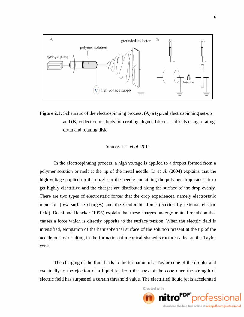
Figure 2.1: Schematic of the electrospinning process. (A) a typical electrospinning set-up
and (B) collection methods for creating aligned fibrous scaffolds using rotating
drum and rotating disk.
Source: Lee et al. 2011
In the electrospinning process, a high voltage is applied to a droplet formed from a
polymer solution or melt at the tip of the metal needle. Li et al. (2004) explains that the
high voltage applied on the nozzle or the needle containing the polymer drop causes it to
get highly electrified and the charges are distributed along the surface of the drop evenly.
There are two types of electrostatic forces that the drop experiences, namely electrostatic
repulsion (b/w surface charges) and the Coulombic force (exerted by external electric
field). Doshi and Renekar (1995) explain that these charges undergo mutual repulsion that
causes a force which is directly opposite to the surface tension. When the electric field is
intensified, elongation of the hemispherical surface of the solution present at the tip of the
needle occurs resulting in the formation of a conical shaped structure called as the Taylor
cone.
The charging of the fluid leads to the formation of a Taylor cone of the droplet and
eventually to the ejection of a liquid jet from the apex of the cone once the strength of
electric field has surpassed a certain threshold value. The electrified liquid jet is accelerated
7
towards the grounded collector by the electric field and thins rapidly due to the evaporation
of the solvent and elongation by stretching and whipping. The solidified fiber is often
deposited as a randomly oriented, nonwoven mat of nanofibers (Li et al., 2004).
Huang et al. (2003) states that further increasing the electric field, a critical value is
attained with which the repulsive electrostatic force overcomes the surface tension and the
charged jet of the fluid is ejected from the tip of the Taylor cone. The discharged polymer
solution jet undergoes an instability and elongation process, which allows the jet to become
very long and thin. Meanwhile, the solvent evaporates, leaving behind a charged polymer
fiber. In the case of the melt the discharged jet solidifies when it travels in the air.
Based on a review conducted by Pham et al. (2006), the shape of the base depends
upon the surface tension of the liquid and the force of the electric field; jets can be ejected
from surfaces that are essentially flat if the electric field is strong enough. Charging of the
jet occurs at the base, with solutions of higher conductivity being more conducive to jet
formation. Lee and Arinzeh (2011) justify that the most common method to collect the
electrospun nanofibers is on a high speed rotating drum or disk (Figure 2.1(B)). This allows
for the fiber to collect along the direction of rotation. Small diameter tubes can also be
fabricated by this method and have been used in vascular repair studies. A high rotation
speed produces increased fiber alignment as compared to lower rotation speed, but may
cause fiber discontinuity.
2.2 General Set-Ups and Processing Parameters
Electrospinning is an efficient, inexpensive technique in which the whole apparatus
is compact. The basic set up is a syringe with a metal needle connected to a syringe pump,
grounded collector, and a high voltage source. Over the years researchers have found the
need to modify the set up for various reasons, but the basic principle has been the same.
Lu et al. (2008) states that although the setup for electrospinning is extremely
simple, the detailed experimental and theoretical analysis reveals that the electrospinning
8
process is highly complex. Doshi and Renekar (1995) explain that many parameters can
influence the transformation of polymer solution into nanofibers through electrospinning.
These parameters include (a) the solution properties such as viscosity, elasticity,
conductivity, and surface tension, (b) governing variables such as hydrostatic pressure in
the capillary tip, and the gap (distance between the tip and the collecting screen), and (c)
ambient parameters such as solution temperature, humidity, and air velocity in the
electrospinning chamber.
2.2.1 Needle Diameter (Nozzle)
Rao (2009) elaborates that in electrospinning, a precise amount of polymer solution
is taken in the capillary or spinneret. The nozzle (usually the syringe needle set up)
determines the amount of polymer melt that comes out, which in turn affects the size of the
drop being formed and also the pressure or the amount of force required by the pump so as
to push the melt out. If the polymer melt is less viscous, then it can easily come out of the
nozzle. The polymer melt is usually a thick highly viscous fluid. So, if the nozzle is too
small, then unless it‟s less viscous, the melt cannot be forced out. Hence, an appropriate
nozzle should be chosen. Different types of nozzles or spinnerets have been used over the
years. Warner et al. (1999) used a spinneret which was basically a stainless steel tube with
an outer diameter of 1/16th inch and inner diameter of 0.04 inch. They have also used a
capillary of 1.6mm in their experiments.
According to Mo et al. (2004), the internal diameter of the needle of the pipette
orifice has a certain effect on the electrospinning process. A smaller internal diameter was
found to reduce the clogging as well as the amount of beads on the electrospun fibers. The
reduction in the clogging could be due to less exposure of the solution to the atmosphere
during electrospinning. Decrease in the internal diameter of the orifice was also found to
cause a reduction in the diameter of the electrospun fibers. When the size of the droplet at
the tip of the orifice is decreased, the surface tension of the droplet increases. Zhao et al.
(2004) argues that if the diameter of the orifice is too small, it may not be possible to
extrude a droplet of solution at the tip of the orifice.
9
2.2.2 Distance between Tip and Collector
Sill et al. (2008) states that the distance between capillary tip and collector can also
influence fiber size by 1-2 orders of magnitude. Additionally, this distance can dictate
whether the end result is electrospinning or electrospraying. Doshi and Reneker found that
the fiber diameter decreased with increasing distances from the Taylor cone. In another
study, Jaegar et al. (1998) electrospun fibers from a PEO/water solution and examined the
fiber diameter as a function of the distance from the Taylor cone. They found that the
diameter of the fiber jet decreased approximately 2-fold, from 19 to 9 µm after travelling
distances of 1 and 3.5cm, respectively.
The distance between the tip and the collector will have a direct influence in flight
time and electric field strength. For fibers to form, the electrospinning jet must be allowed
time for most of the solvents to be evaporated. When the distance between the tip and the
collector is reduced, the jet will have shorter distance to travel before it reaches the
collector plate. The electric field strength will increase at the same time and this will
increase the acceleration of the jet to the collector. As a result, there may not have enough
time for solvents to evaporate when it reach the collector. When the distance is too low,
excess solvents may cause the fibers to merge when they contact to form junctions resulting
in intra layer bonding (Ramakrishna et al., 2005).
In a study constructed by Dietzel et al. (2001), they had a needle to collector
distance of about 20cm while in Warner et al. (1999) study, they had a distance of 15cm.
Subbiah et al. (2004) explains that morphology of the electrospun fibers depends on the
evaporation rate, deposition time, and whipping interval. If the distance is too small, it
would result in collection of wet fibers and fibers having a bead-like structure. Hence, a
suitable distance should be set so that the fibers have enough time to dry.
10
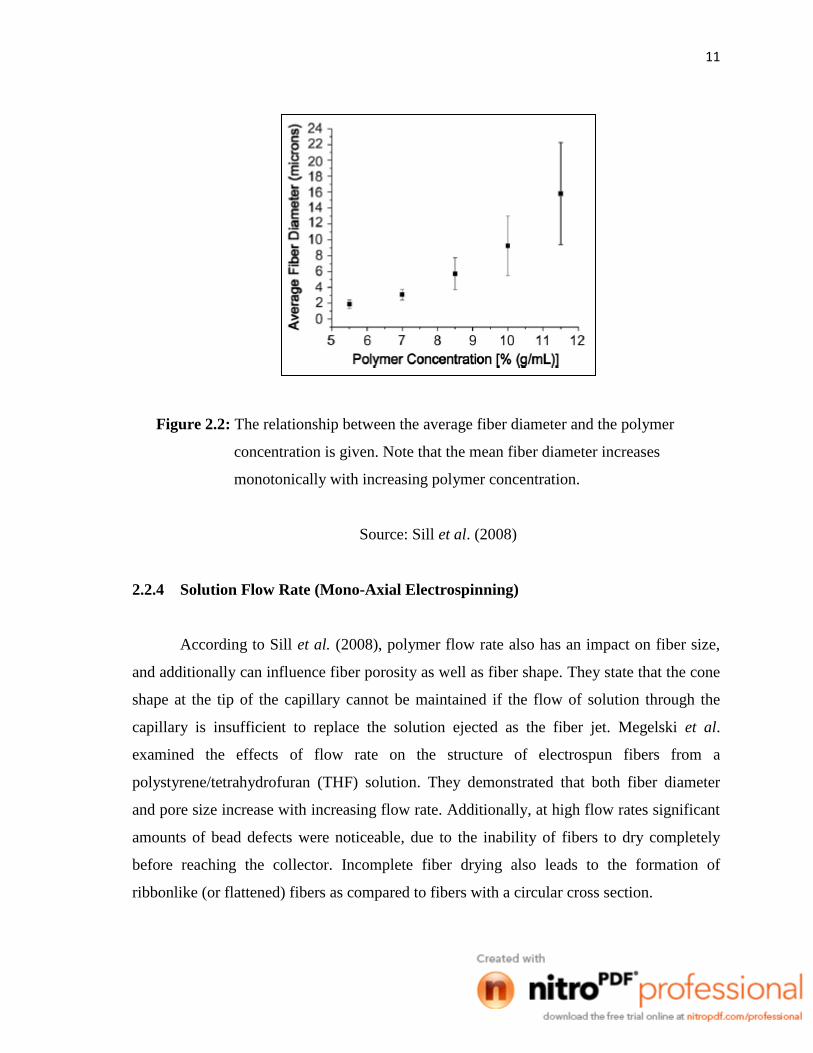
2.2.3 Polymer Concentration
Sill et al. (2008) justifies that polymer concentration determines the spinnability of
a solution. The solution must have high enough polymer concentration for chain
entanglements to occur. However, the solution cannot be either too dilute or too
concentrated. The polymer concentration influences both the viscosity and surface tension
of the solution. If the solution is too dilute, the polymer fiber will break up into droplets
before reaching the collector due to the effect of surface tension. If the solution is too
concentrated, then fibers cannot be formed due to the high viscosity which makes it
difficult to control the solution flow rate through the capillary. An optimum range of
polymer concentration exists in which fibers can be electrospun when all other parameters
are held constant. Figure 2.2 shows that the mean fiber diameter increases monotonically
with increasing polymer concentration.
On the other hand, Doshi and Reneker had electrospun fibers from PEO/water
solutions containing various PEO concentrations and found that solution with viscosity less
than 800 centipoises broke up into droplets upon electrospinning while solutions with
viscosity greater than 4000 centipoises were too thick to electrospin. In many experiments
it has been shown that within the optimal range of polymer concentrations fiber diameter
increases with increasing polymer concentration. Deitzel et al. found that fiber diameter of
fibers electrospun from PEO/water solution were related to PEO concentration by a power
law relationship.
11
Figure 2.2: The relationship between the average fiber diameter and the polymer
concentration is given. Note that the mean fiber diameter increases
monotonically with increasing polymer concentration.
Source: Sill et al. (2008)
2.2.4 Solution Flow Rate (Mono-Axial Electrospinning)
According to Sill et al. (2008), polymer flow rate also has an impact on fiber size,
and additionally can influence fiber porosity as well as fiber shape. They state that the cone
shape at the tip of the capillary cannot be maintained if the flow of solution through the
capillary is insufficient to replace the solution ejected as the fiber jet. Megelski et al.
examined the effects of flow rate on the structure of electrospun fibers from a
polystyrene/tetrahydrofuran (THF) solution. They demonstrated that both fiber diameter
and pore size increase with increasing flow rate. Additionally, at high flow rates significant
amounts of bead defects were noticeable, due to the inability of fibers to dry completely
before reaching the collector. Incomplete fiber drying also leads to the formation of
ribbonlike (or flattened) fibers as compared to fibers with a circular cross section.
12
According to Ramakrishna et al. (2005), the flow rate will determine the amount of
solution available for electrospinning. For a given voltage, there is a corresponding feed
rate if a stable Taylor cone is to be maintained. When the feed rate is increased, there is a
corresponding increase in the fiber diameter or beads size. This is due to greater volume of
solution that is ejected from the needle tip. Yuan et al. (2004) argues that a lower feed rate
is more desirable as the solvent will have more time for evaporation. The jet will take a
long time to dry due to the greater volume of solution drawn from the needle tip.
The rate at which the polymer comes out of the needle/nozzle is an important factor
in electrospinning. Doshi and Reneker (1993) filled a capillary tube with the polymer
solution and a hydrostatic pressure was established by an air pump which was controlled by
valves and was read on a manometer. Warner et al. (1999) used a digitally controlled,
positive displacement syringe pump (Harvard Apparatus PHD 2000) and had typical flow
rates ranging between 0.2 ml/min to 1 ml/min. Dietzel et al. (2001), used a flow rate of
0.05ml/hr achieved using a Harvard 2000 syringe pump. Subbiah et al. (2004) mentioned
that the material transfer rate and the jet velocity are directly dependent on this feature.
They have also mentioned that researchers have found that the higher the polymer flow
rate, bigger the diameter of the fibers.
2.2.5 Voltage Supply
One of the most studied parameters among the controlled variables is the effect of
field strength or applied voltage. Rao (2009) explains that a suitable high voltage is applied
on the needle such that, when it exceeds a critical value, the drop which is induced at the tip
of the needle distorts into the shape of a cone and a charged jet of the polymer erupts from
the apex of this cone. This jet gets drawn towards the grounded collector by the electric
field. Similarly, Warner et al. (1999) used a Gamma High Voltage Research ES30-P power
supply to induce a voltage up to 20 kV in their experiments. Dietzel et al. (2001) found this
critical value to be 5 kV. They have applied voltages ranging from 5kV-15kV in their
experiments.
13
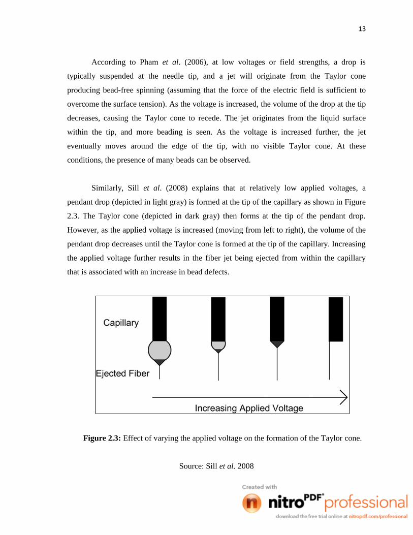
According to Pham et al. (2006), at low voltages or field strengths, a drop is
typically suspended at the needle tip, and a jet will originate from the Taylor cone
producing bead-free spinning (assuming that the force of the electric field is sufficient to
overcome the surface tension). As the voltage is increased, the volume of the drop at the tip
decreases, causing the Taylor cone to recede. The jet originates from the liquid surface
within the tip, and more beading is seen. As the voltage is increased further, the jet
eventually moves around the edge of the tip, with no visible Taylor cone. At these
conditions, the presence of many beads can be observed.
Similarly, Sill et al. (2008) explains that at relatively low applied voltages, a
pendant drop (depicted in light gray) is formed at the tip of the capillary as shown in Figure
2.3. The Taylor cone (depicted in dark gray) then forms at the tip of the pendant drop.
However, as the applied voltage is increased (moving from left to right), the volume of the
pendant drop decreases until the Taylor cone is formed at the tip of the capillary. Increasing
the applied voltage further results in the fiber jet being ejected from within the capillary
that is associated with an increase in bead defects.
Figure 2.3: Effect of varying the applied voltage on the formation of the Taylor cone.
Source: Sill et al. 2008
14
2.2.6 Humidity
The humidity was varied by Casper et al. (2004), while spinning polystyrene
solutions. Their work showed that increasing the humidity resulted in the appearance of
small circular pores on the surface of the fibers and further increasing the humidity will
lead to the pores coalescing as determined by atomic force microscopy. At high humidity, it
is likely that water condenses on the fiber surface when electrospinning is carried out under
normal atmosphere. As a result, this may have an influence on the fiber morphology
especially polymers dissolved in volatile solvents (Megelski et al., 2002). According to
him, water vapor may condense on the jet surface due to jet surface cooling as a result of
rapid evaporation of the volatile solvent. Pores are created when both water and solvent
eventually evaporate. Pores seen on electrospun fibers mat due to the dynamic condition of
the electrospinning jet as compared to static condition
The humidity of the environment will also determine the rate of solvent evaporation
of the solvent in the solution. At a very low humidity, a volatile solvent may dries very
rapidly. The solvent evaporation may be faster than the removal of the solvent from the
needle tip. As a result, the electrospinning process may only be carried out for a few
minutes before the needle tip is clogged (Ramakrishna et al., 2006).
2.3 Co-Axial Electrospinning
In many cases, the application of nanofibers is required to keep the functionalizing
agents (for example, biomolecules such as enzymes, proteins, drugs, viruses, and bacteria)
in the fluid environment to maintain their functionality. In order to meet this requirement,
core-shell nanofibers were prepared by a modified electrospinning process, co-axial
electrospinning. According to Yarin (2010) in his review, he mentions that co-axial
electrospinning or co-electrospinning of core–shell micro- and nanofibers was born 7 years
ago as a branch of nanotechnology which bifurcated from a previously known
electrospinning. Through electrospinning, co-electrospinning inherited roots in polymer
science and electrohydrodynamics, while some additional genes from textile science and