EN54 - JUNO-NET MAINTENANCE...
29
OPERATION & MAINTENANCE MANUAL JUNO-NET Fire Alarm Control Panel EN-54 JUNO-NET EN-54 MAINTENANCE MANUAL 21-08-2005 REVISION 1.0 OPERATION & ss ss
Transcript of EN54 - JUNO-NET MAINTENANCE...

OPERATION&
MAINTENANCEMANUAL
JUNO-NET
Fire Alarm Control PanelEN-54
JUNO-NET EN-54 MAINTENANCE MANUAL 21-08-2005REVISION 1.0OPERATION & �� ��
JUNO-NET
CONTENTS
SECTION 1 -
1.1 Description of the fire control panel fascia................................................
1.2 Alarm.................................................................................................
1.9 Caretaker Test Mode.............................................................................
1.10 Disablements......................................................................................
1.10.1 Selected detectors..............................................................
1.10.3 Sounders Enable/Disable....................................................
2.1 Printer paper replacement.....................................................................
2.2 SIM CARD replacement.......................................................................
2.3 Main control board fuse........................................................................
2.4 Connection board fuses........................................................................
2.5 Sub-panel fuses...................................................................................
2.6 Battery voltage and charger checks.........................................................
2.7 Replacing the Mains Fuse......................................................................
2.8 Use of programming functions for maintenance.......................................
2.9 Getting into Programming Mode............................................................
2.10 Logbook.............................................................................................
2.10 Event data sheet...................................................................................
OPERATION
1.3 Reset the system...................................................................................
1.4 Sound and silence the alarms.................................................................
1.5 Read the Fire, Fault, Test and Disabled queues..........................................
1.6 Active Delays.......................................................................................
1.7 Lamp Test............................................................................................
1.8 Perform a fire drill.................................................................................
1.10.2 Auxiliary relays...................................................................
1.10.4 Zones Enable/Disable.........................................................
1.11 If the panel displays a fault.....................................................................
1.12 If the panel displays a pre-alarm............................................................
SECTION 2 - MAINTENANCE
2
4
5
5
6
7
8
9
10
12
12
13
13
14
14
14
15
16
17
17
17
18
18
19
22
27
28
1JUNO-NET EN-54 MAINTENANCE MANUAL 21-08-2005REVISION 1.0OPERATION & �� ��
FIRE
FAULT
PRE-ALARM
TEST
DISABLED
SYSTEM ON
ALARM FAULT
SUPPLY FAULT
SYSTEM FAULT
TRANS. FAULT
PAPER FEED
LAMP TEST
SYSTEM RESET
INTERNAL BUZZER
SILENCE
DISABLED
TEST
FAULT
FIRE
AUXILIARY
RELAYS
SOUNDERS
ENABLE/DISABLE
SELECTED
DETECTORS
DELAYS
ACTIVE
STATUS
FAULTS CONTROLS DISABLEMENTS
QUEUE REVIEW
SILENCE/RESOUND
ALARMS
ESC OK
FIRE ALARM SYSTEM
COMPLIES WITH
-2: 1997 / AC: 1999
EN54-4: 1997 / AC: 1999
EN54
JUNO-NET
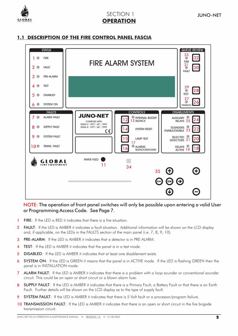
1.1 DESCRIPTION OF THE FIRE CONTROL PANEL FASCIA
FIRE
FAULT
PRE-ALARM
TEST
DISABLED
SYSTEM ON
ALARM FAULT
: If the LED is RED it indicates that there is a fire situation.
: If the LED is AMBER it indicates a fault situation. Additional information will be shown on the LCD displayand, if applicable, on the LEDs in the FAULTS section of the main panel (i.e. 7, 8, 9, 10).
: If the LED is AMBER it indicates that a detector is in PRE-ALARM.
: If the LED is AMBER it indicates that the panel is in a test mode.
: If the LED is AMBER it indicates that at least one disablement exists.
: If the LED is GREEN it means that the panel is in ACTIVE mode. If the LED is flashing GREEN then thepanel is in INSTALLATION mode.
: If the LED is AMBER it indicates that there is a problem with a loop sounder or conventional soundercircuit. This could be an open or short circuit or a blown alarm fuse.
: If the LED is AMBER it indicates that there is a Primary Fault, a Battery Fault or that there is an EarthFault. Further details will be shown on the LCD display as to the type of supply fault.
: If the LED is AMBER it indicates that there is 5 Volt fault or a processor/program failure.
: If the LED is AMBER it indicates that there is an open or short circuit in the fire brigadetransmission circuit.
SUPPLY FAULT
SYSTEM FAULT
TRANSMISSION FAULT
1
2
3
4
5
6
7
8
9
10
OPERATIONSECTION 1
2
1
2
3
4
5
6
7
8
9
10
12
14
15
16
13
17
1819
21
23 22
20
25 24
2726
29
30
3233
31
28
11 3435
JUNO-NET EN-54 MAINTENANCE MANUAL 21-08-2005REVISION 1.0OPERATION & �� ��
NOTE: The operation of front panel switches will only be possible upon entering a valid Useror Programming Access Code. See Page 7.
PAPER FEED
INTERNAL BUZZER SILENCE
INTERNAL BUZZER SILENCE
SYSTEM RESET
LAMP TEST
ALARMS SILENCE/RESOUND
ALARMS SILENCE/RESOUND:
DELAYS ACTIVE:
DELAYS ACTIVE:
SELECTED DETECTORS
SELECTED DETECTORS
SOUNDERS ENABLE/DISABLE
SOUNDERS ENABLE/DISABLE
AUXILIARY RELAYS
AUXILIARY RELAYS
DISABLED
DISABLED
TEST
TEST
FAULT
FAULT
FIRE
FIRE
INFRA-RED SENSOR
KEYPAD:
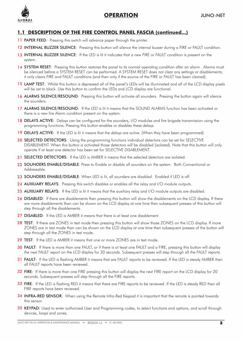
: Pressing this switch will advance paper through the printer.
: Pressing this button will silence the internal buzzer during a FIRE or FAULT condition.
: If the LED is lit it indicates that a new FIRE or FAULT condition is present on thesystem.
: Pressing this button restores the panel to its normal operating condition after an alarm. Alarms mustbe silenced before a SYSTEM RESET can be performed. A SYSTEM RESET does not clear any settings or disablements;it only clears FIRE and FAULT conditions (and then only if the source of the FIRE or FAULT has been cleared).
: Whilst this button is depressed all of the panel’s LEDs will be illuminated and all of the LCD display pixelswill be set to black. Use this button to confirm the LEDs and LCD display are functional.
: Pressing this button will activate all sounders. Pressing the button again will silencethe sounders.
If the LED is lit it means that the SOUND ALARMS function has been activated orthere is a new fire Alarm condition present on the system.
Delays can be configured for the sounders, I/O modules and fire brigade transmission using theprogramming functions. Pressing this button enables or disables these delays.
If the LED is lit it means that the delays are active. (When they have been programmed)
: Using the programming functions individual detectors can be set for SELECTIVEDISABLEMENT. When this button is activated those detectors will be disabled (isolated). Note that this button will onlyoperate if at least one detector has been set for SELECTIVE DISABLEMENT.
: If the LED is AMBER it means that the selected detectors are isolated.
: Press to Enable or disable all sounders on the system. Both Conventional orAddressable.
: When LED is lit, all sounders are disabled. Enabled if LED is off.
: Pressing this switch disables or enables all the relay and I/O module outputs.
: If the LED is lit it means that the auxiliary relay and I/O module outputs are disabled.
: If there are disablements then pressing this button will show the disablements on the LCD display. If thereare more disablements than can be shown on the LCD display at one time then subsequent presses of this button willstep through all the disablements.
: If the LED is AMBER it means that there is at least one disablement.
: If there are ZONES in test mode then pressing this button will show those ZONES on the LCD display. If moreZONES are in test mode than can be shown on the LCD display at one time then subsequent presses of the button willstep through all the ZONES in test mode.
: If the LED is AMBER it means that one or more ZONES are in test mode.
: If there is more than one FAULT, or if there is at least one FAULT and a FIRE, pressing this button will displaythe next FAULT report on the LCD display for 20 seconds. Subsequent presses will step through all the FAULT reports.
: If the LED is flashing AMBER it means that are FAULT reports to be reviewed. If the LED is steady AMBER thenall FAULT reports have been reviewed.
: If there is more than one FIRE pressing this button will display the next FIRE report on the LCD display for 20seconds. Subsequent presses will step through all the FIRE reports.
: If the LED is flashing RED it means that there are FIRE reports to be reviewed. If the LED is steady RED then allFIRE reports have been reviewed.
: When using the Remote Infra-Red Keypad it is important that the remote is pointed towardsthis sensor.
Used to enter authorized User and Programming codes, to select functions and options, and scroll throughdevices, loops and zones.
11
12
13
14
15
16
17
18
19
20
21
22
23
24
25
26
27
28
29
30
31
32
33
34
35
OPERATION JUNO-NET
1.1 DESCRIPTION OF THE FIRE CONTROL PANEL FASCIA (continued...)
3JUNO-NET EN-54 MAINTENANCE MANUAL 21-08-2005REVISION 1.0OPERATION & �� ��
FIRE
FAULT
PRE-ALARM
TEST
DISABLED
SYSTEM ON
ALARM FAULT
SUPPLY FAULT
SYSTEM FAULT
TRANS. FAULT
PAPER FEED
LAMP TEST
SYSTEM RESET
INTERNAL BUZZER
SILENCE
DISABLED
TEST
FAULT
FIRE
AUXILIARY
RELAYS
SOUNDERS
ENABLE/DISABLE
SELECTED
DETECTORS
DELAYS
ACTIVE
STATUS
FAULTS CONTROLS DISABLEMENTS
QUEUE REVIEW
SILENCE/RESOUND
ALARMS
ESC OK
FIRE ALARM SYSTEM
COMPLIES WITH
-2: 1997 / AC: 1999
EN54-4: 1997 / AC: 1999
EN54
FIRE
FAULT
PRE-ALARM
TEST
DISABLED
SYSTEM ON
ALARM FAULT
SUPPLY FAULT
SYSTEM FAULT
TRANS. FAULT
PAPER FEED
LAMP TEST
SYSTEM RESET
INTERNAL BUZZER
SILENCE
DISABLED
TEST
FAULT
FIRE
AUXILIARY
RELAYS
SOUNDERS
ENABLE/DISABLE
SELECTED
DETECTORS
DELAYS
ACTIVE
STATUS
FAULTS CONTROLS DISABLEMENTS
QUEUE REVIEW
SILENCE/RESOUND
ALARMS
ESC OK
FIRE ALARM SYSTEM
COMPLIES WITH
-2: 1997 / AC: 1999
EN54-4: 1997 / AC: 1999
EN54
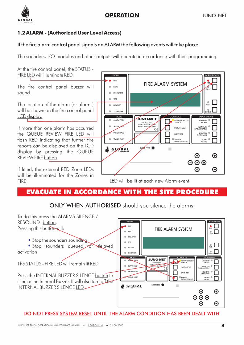
To do this press the ALARMS SILENCE /RESOUND .Pressing this button will:
Stop the sounders soundingStop sounders queued for delayed
activation
The STATUS - FIRE will remain lit RED.
Press the INTERNAL BUZZER SILENCE tosilence the Internal Buzzer. It will also turn off theINTERNAL BUZZER SILENCE
button
LED
button
LED
At the fire control panel, the STATUS -FIRE will illuminate RED.
The fire control panel buzzer willsound.
The location of the alarm (or alarms)will be shown on the fire control panel
If more than one alarm has occurredthe QUEUE REVIEW FIRE willflash RED indicating that further firereports can be displayed on the LCDdisplay by pressing the QUEUEREVIEW FIRE .
If fitted, the external RED Zone LEDswill be illuminated for the Zones inFIRE.
LED
LCD display.
LED
button
JUNO-NET
1.2 ALARM - (Authorized User Level Access)
If the fire alarm control panel signals an ALARM the following events will take place:
The sounders, I/O modules and other outputs will operate in accordance with their programming.
EVACUATE IN ACCORDANCE WITH THE SITE PROCEDURE
ONLY WHEN AUTHORISED should you silence the alarms.
DO NOT PRESS UNTIL THE ALARM CONDITION HAS BEEN DEALT WITH.SYSTEM RESET
OPERATION
4JUNO-NET EN-54 MAINTENANCE MANUAL 21-08-2005REVISION 1.0OPERATION & �� ��
LED will be lit at each new Alarm event
FIRE
FAULT
PRE-ALARM
TEST
DISABLED
SYSTEM ON
ALARM FAULT
SUPPLY FAULT
SYSTEM FAULT
TRANS. FAULT
PAPER FEED
LAMP TEST
SYSTEM RESET
INTERNAL BUZZER
SILENCE
DISABLED
TEST
FAULT
FIRE
AUXILIARY
RELAYS
SOUNDERS
ENABLE/DISABLE
SELECTED
DETECTORS
DELAYS
ACTIVE
STATUS
FAULTS CONTROLS DISABLEMENTS
QUEUE REVIEW
SILENCE/RESOUND
ALARMS
ESC OK
FIRE ALARM SYSTEM
COMPLIES WITH
-2: 1997 / AC: 1999
EN54-4: 1997 / AC: 1999
EN54
FIRE
FAULT
PRE-ALARM
TEST
DISABLED
SYSTEM ON
ALARM FAULT
SUPPLY FAULT
SYSTEM FAULT
TRANS. FAULT
PAPER FEED
LAMP TEST
SYSTEM RESET
INTERNAL BUZZER
SILENCE
DISABLED
TEST
FAULT
FIRE
AUXILIARY
RELAYS
SOUNDERS
ENABLE/DISABLE
SELECTED
DETECTORS
DELAYS
ACTIVE
STATUS
FAULTS CONTROLS DISABLEMENTS
QUEUE REVIEW
SILENCE/RESOUND
ALARMS
ESC OK
FIRE ALARM SYSTEM
COMPLIES WITH
-2: 1997 / AC: 1999
EN54-4: 1997 / AC: 1999
EN54
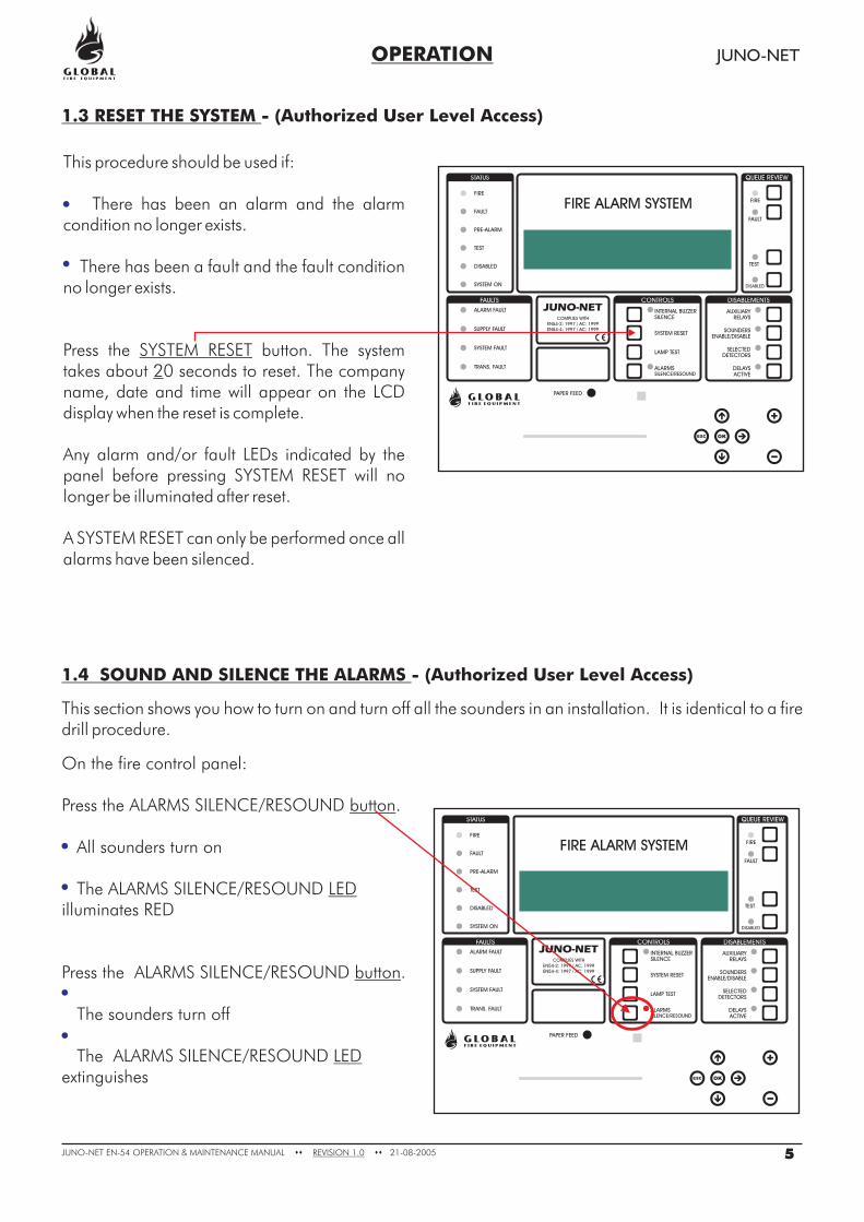
On the fire control panel:
Press the ALARMS SILENCE/RESOUND .
All sounders turn on
Theilluminates RED
Press the .
The sounders turn off
Theextinguishes
button
LED
button
LED
ALARMS SILENCE/RESOUND
ALARMS SILENCE/RESOUND
ALARMS SILENCE/RESOUND
1.4 SOUND AND SILENCE THE ALARMS - (Authorized User Level Access)
This section shows you how to turn on and turn off all the sounders in an installation. It is identical to a firedrill procedure.
This procedure should be used if:
There has been an alarm and the alarmcondition no longer exists.
There has been a fault and the fault conditionno longer exists.
Press the button. The systemtakes about 0 seconds to reset. The companyname, date and time will appear on the LCDdisplay when the reset is complete.
Any alarm and/or fault LEDs indicated by thepanel before pressing will nolonger be illuminated after reset.
A SYSTEM RESET can only be performed once allalarms have been silenced.
SYSTEM RESET2
SYSTEM RESET
OPERATION JUNO-NET
1.3 RESET THE SYSTEM - (Authorized User Level Access)
5JUNO-NET EN-54 MAINTENANCE MANUAL 21-08-2005REVISION 1.0OPERATION & �� ��
FIRE
FAULT
PRE-ALARM
TEST
DISABLED
SYSTEM ON
ALARM FAULT
SUPPLY FAULT
SYSTEM FAULT
TRANS. FAULT
PAPER FEED
LAMP TEST
SYSTEM RESET
INTERNAL BUZZER
SILENCE
DISABLED
TEST
FAULT
FIRE
AUXILIARY
RELAYS
SOUNDERS
ENABLE/DISABLE
SELECTED
DETECTORS
DELAYS
ACTIVE
STATUS
FAULTS CONTROLS DISABLEMENTS
QUEUE REVIEW
SILENCE/RESOUND
ALARMS
ESC OK
FIRE ALARM SYSTEM
COMPLIES WITH
-2: 1997 / AC: 1999
EN54-4: 1997 / AC: 1999
EN54
FIRE
FAULT
PRE-ALARM
TEST
DISABLED
SYSTEM ON
ALARM FAULT
SUPPLY FAULT
SYSTEM FAULT
TRANS. FAULT
PAPER FEED
LAMP TEST
SYSTEM RESET
INTERNAL BUZZER
SILENCE
DISABLED
TEST
FAULT
FIRE
AUXILIARY
RELAYS
SOUNDERS
ENABLE/DISABLE
SELECTED
DETECTORS
DELAYS
ACTIVE
STATUS
FAULTS CONTROLS DISABLEMENTS
QUEUE REVIEW
SILENCE/RESOUND
ALARMS
ESC OK
FIRE ALARM SYSTEM
COMPLIES WITH
-2: 1997 / AC: 1999
EN54-4: 1997 / AC: 1999
EN54
OPERATION JUNO-NET
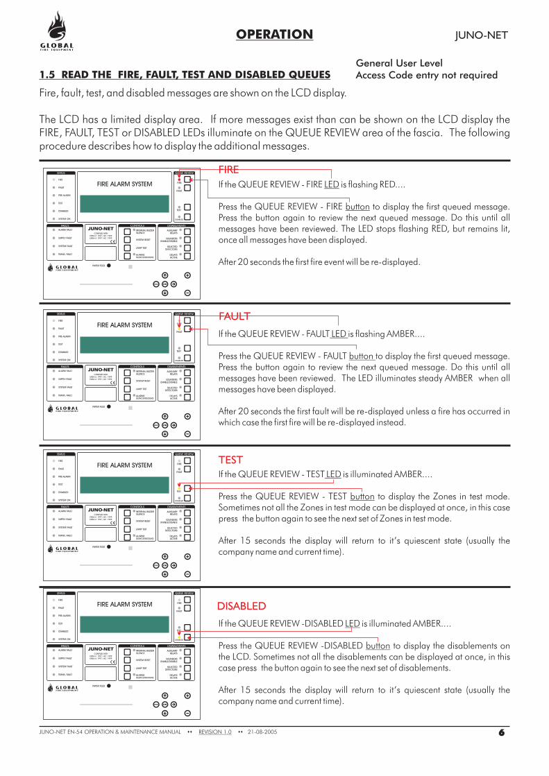
1.5 READ THE FIRE, FAULT, TEST AND DISABLED QUEUES
Fire, fault, test, and disabled messages are shown on the LCD display.
The LCD has a limited display area. If more messages exist than can be shown on the LCD display theFIRE, FAULT, TEST or DISABLED LEDs illuminate on the QUEUE REVIEW area of the fascia. The followingprocedure describes how to display the additional messages.
If the QUEUE REVIEW - FIRE is flashing RED....
Press the QUEUE REVIEW - FIRE to display the first queued message.Press the button again to review the next queued message. Do this until allmessages have been reviewed. The LED stops flashing RED, but remains lit,once all messages have been displayed.
After 20 seconds the first fire event will be re-displayed.
LED
button
If the QUEUE REVIEW - FAULT is flashing AMBER....
Press the QUEUE REVIEW - FAULT
The LED illuminates steady AMBER when allmessages have been displayed.
After 20 seconds the first fault will be re-displayed unless a fire has occurred inwhich case the first fire will be re-displayed instead.
LED
button to display the first queued message.Press the button again to review the next queued message. Do this until allmessages have been reviewed.
If the QUEUE REVIEW - TEST is illuminated AMBER....
Press the QUEUE REVIEW - TEST to display the Zones in test mode.Sometimes not all the Zones in test mode can be displayed at once, in this casepress the button again to see the next set of Zones in test mode.
After 15 seconds the display will return to it’s quiescent state (usually thecompany name and current time).
LED
button
If the QUEUE REVIEW -DISABLED is illuminated AMBER....
Press the QUEUE REVIEW -DISABLED to display the disablements onthe LCD.
LED
buttonSometimes not all the disablements can be displayed at once, in this
case press the button again to see the next set of disablements.
After 15 seconds the display will return to it’s quiescent state (usually thecompany name and current time).
FIRE
FAULT
TEST
DISABLED
6JUNO-NET EN-54 MAINTENANCE MANUAL 21-08-2005REVISION 1.0OPERATION & �� ��
FIRE
FAULT
PRE-ALARM
TEST
DISABLED
SYSTEM ON
ALARM FAULT
SUPPLY FAULT
SYSTEM FAULT
TRANS. FAULT
PAPER FEED
LAMP TEST
SYSTEM RESET
INTERNAL BUZZER
SILENCE
DISABLED
TEST
FAULT
FIRE
AUXILIARY
RELAYS
SOUNDERS
ENABLE/DISABLE
SELECTED
DETECTORS
DELAYS
ACTIVE
STATUS
FAULTS CONTROLS DISABLEMENTS
QUEUE REVIEW
SILENCE/RESOUND
ALARMS
ESC OK
FIRE ALARM SYSTEM
COMPLIES WITH
-2: 1997 / AC: 1999
EN54-4: 1997 / AC: 1999
EN54
General User LevelAccess Code entry not required
OPERATION JUNO-NET
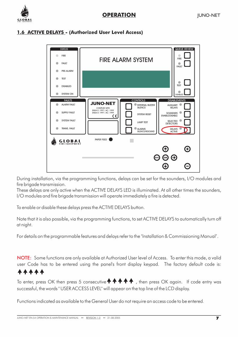
1.6 ACTIVE DELAYS - (Authorized User Level Access)
During installation, via the programming functions, delays can be set for the sounders, I/O modules andfire brigade transmission.These delays are only active when the ACTIVE DELAYS LED is illuminated. At all other times the sounders,I/O modules and fire brigade transmission will operate immediately a fire is detected.
To enable or disable these delays press the ACTIVE DELAYS button.
Note that it is also possible, via the programming functions, to set ACTIVE DELAYS to automatically turn offat night.
For details on the programmable features and delays refer to the ‘Installation & Commissioning Manual’.
7JUNO-NET EN-54 MAINTENANCE MANUAL 21-08-2005REVISION 1.0OPERATION & �� ��
FIRE
FAULT
PRE-ALARM
TEST
DISABLED
SYSTEM ON
ALARM FAULT
SUPPLY FAULT
SYSTEM FAULT
TRANS. FAULT
PAPER FEED
LAMP TEST
SYSTEM RESET
INTERNAL BUZZER
SILENCE
DISABLED
TEST
FAULT
FIRE
AUXILIARY
RELAYS
SOUNDERS
ENABLE/DISABLE
SELECTED
DETECTORS
DELAYS
ACTIVE
STATUS
FAULTS CONTROLS DISABLEMENTS
QUEUE REVIEW
SILENCE/RESOUND
ALARMS
ESC OK
FIRE ALARM SYSTEM
COMPLIES WITH
-2: 1997 / AC: 1999
EN54-4: 1997 / AC: 1999
EN54
NOTE: Some functions are only available at Authorized User level of Access. To enter this mode, a valid
user Code has to be entered using the panel's front display keypad. The factory default code is:
To enter, press OK then press 5 consecutive , then press OK again. If code entry was
successful, the words " USER ACCESS LEVEL" will appear on the top line of the LCD display.
Functions indicated as available to the General User do not require an access code to be entered
�����
�����
.
FIRE
FAULT
PRE-ALARM
TEST
DISABLED
SYSTEM ON
ALARM FAULT
SUPPLY FAULT
SYSTEM FAULT
TRANS. FAULT
PAPER FEED
LAMP TEST
SYSTEM RESET
INTERNAL BUZZER
SILENCE
DISABLED
TEST
FAULT
FIRE
AUXILIARY
RELAYS
SOUNDERS
ENABLE/DISABLE
SELECTED
DETECTORS
DELAYS
ACTIVE
STATUS
FAULTS CONTROLS DISABLEMENTS
QUEUE REVIEW
SILENCE/RESOUND
ALARMS
ESC OK
FIRE ALARM SYSTEM
COMPLIES WITH
-2: 1997 / AC: 1999
EN54-4: 1997 / AC: 1999
EN54
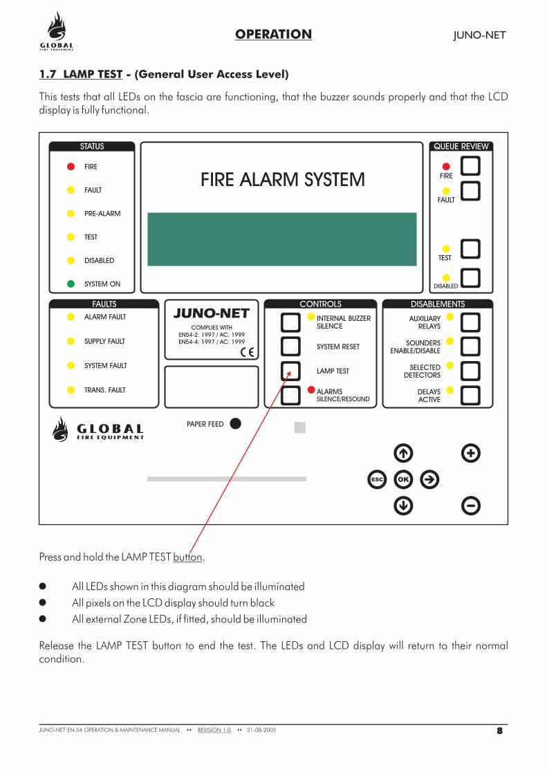
Press and hold the LAMP TEST .
All LEDs shown in this diagram should be illuminated
All pixels on the LCD display should turn black
All external Zone LEDs, if fitted, should be illuminated
Release the LAMP TEST button to end the test. The LEDs and LCD display will return to their normalcondition.
button
�
�
�
OPERATION JUNO-NET
1.7 LAMP TEST - (General User Access Level)
This tests that all LEDs on the fascia are functioning, that the buzzer sounds properly and that the LCDdisplay is fully functional.
8JUNO-NET EN-54 MAINTENANCE MANUAL 21-08-2005REVISION 1.0OPERATION & �� ��
FIRE
FAULT
PRE-ALARM
TEST
DISABLED
SYSTEM ON
ALARM FAULT
SUPPLY FAULT
SYSTEM FAULT
TRANS. FAULT
PAPER FEED
LAMP TEST
SYSTEM RESET
INTERNAL BUZZER
SILENCE
DISABLED
TEST
FAULT
FIRE
AUXILIARY
RELAYS
SOUNDERS
ENABLE/DISABLE
SELECTED
DETECTORS
DELAYS
ACTIVE
STATUS
FAULTS CONTROLS DISABLEMENTS
QUEUE REVIEW
SILENCE/RESOUND
ALARMS
ESC OK
FIRE ALARM SYSTEM
COMPLIES WITH
-2: 1997 / AC: 1999
EN54-4: 1997 / AC: 1999
EN54
OPERATION JUNO-NET
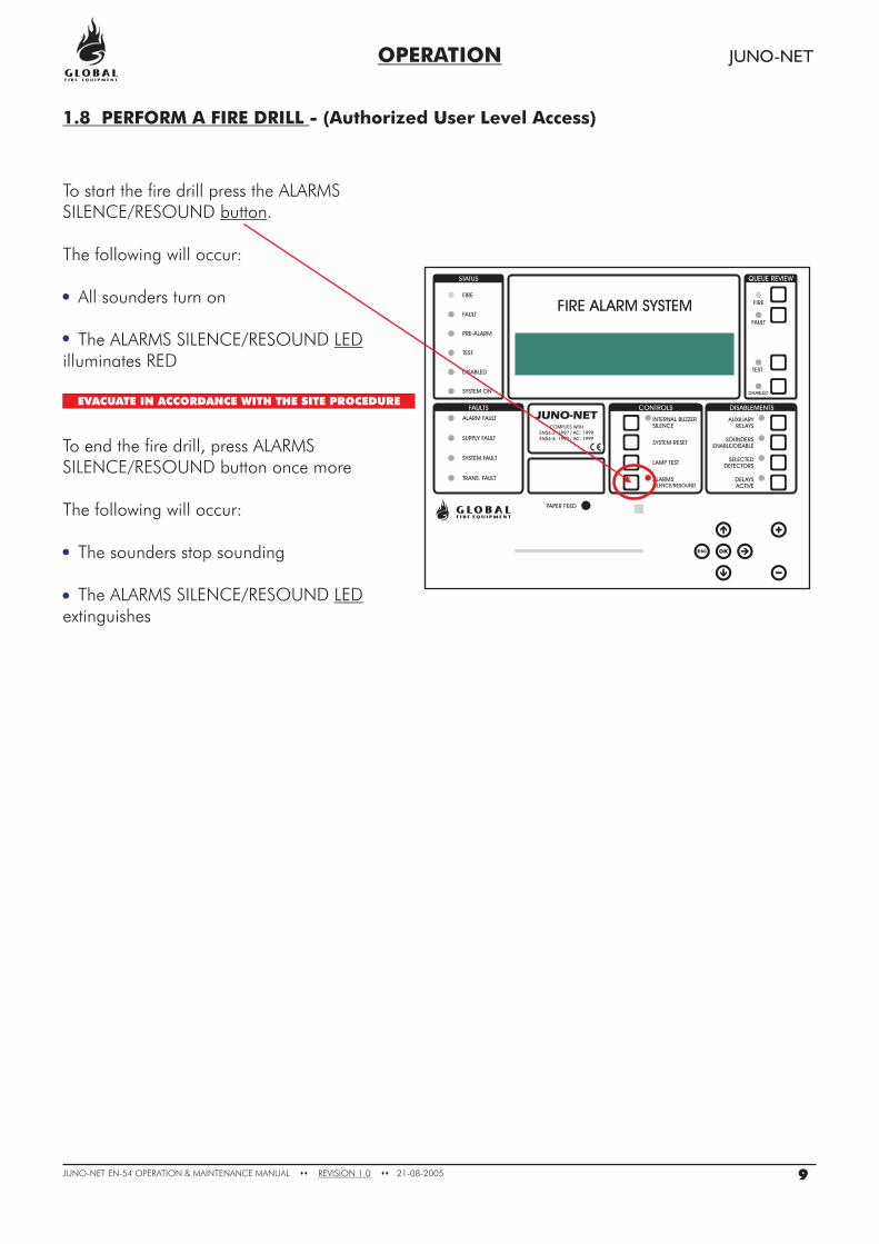
1.8 PERFORM A FIRE DRILL - (Authorized User Level Access)
To start the fire drill press the.
The following will occur:
All sounders turn on
Theilluminates RED
To end the fire drill, press ALARMSSILENCE/RESOUND button once more
The following will occur:
The sounders stop sounding
Theextinguishes
button
LED
LED
ALARMSSILENCE/RESOUND
ALARMS SILENCE/RESOUND
ALARMS SILENCE/RESOUND
EVACUATE IN ACCORDANCE WITH THE SITE PROCEDURE
9JUNO-NET EN-54 MAINTENANCE MANUAL 21-08-2005REVISION 1.0OPERATION & �� ��
FIRE
FAULT
PRE-ALARM
TEST
DISABLED
SYSTEM ON
ALARM FAULT
SUPPLY FAULT
SYSTEM FAULT
TRANS. FAULT
PAPER FEED
LAMP TEST
SYSTEM RESET
INTERNAL BUZZER
SILENCE
DISABLED
TEST
FAULT
FIRE
AUXILIARY
RELAYS
SOUNDERS
ENABLE/DISABLE
SELECTED
DETECTORS
DELAYS
ACTIVE
STATUS
FAULTS CONTROLS DISABLEMENTS
QUEUE REVIEW
SILENCE/RESOUND
ALARMS
ESC OK
FIRE ALARM SYSTEM
COMPLIES WITH
-2: 1997 / AC: 1999
EN54-4: 1997 / AC: 1999
EN54
OPERATION JUNO-NET
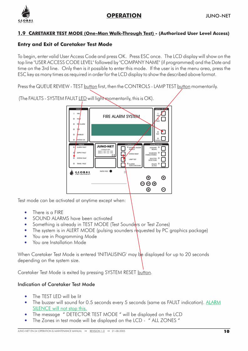
1.9 CARETAKER TEST MODE (One-Man Walk-Through Test) - (Authorized User Level Access)
Entry and Exit of Caretaker Test Mode
To begin, enter valid User Access Code and press OK. Press ESC once. The LCD display will show on thetop line "USER ACCESS CODE LEVEL" followed by "COMPANY NAME" (if programmed) and the Date andtime on the 3rd line. Only then is it possible to enter this mode. If the user is in the menu area, press theESC key as many times as required in order for the LCD display to show the described above format.
Press the QUEUE REVIEW - TEST first, then the CONTROLS - LAMP TEST momentarily.
(The FAULTS - SYSTEM FAULT
button button
LED will light momentarily, this is OK).
Test mode can be activated at anytime except when:
· There is a FIRE· SOUND ALARMS have been activated· Something is already in TEST MODE (Test Sounders or Test Zones)· The system is in ALERT MODE (pulsing sounders requested by PC graphics package)· You are in Programming Mode· You are Installation Mode
When Caretaker Test Mode is entered 'INITIALISING' may be displayed for up to 20 secondsdepending on the system size.
Caretaker Test Mode is exited by pressing SYSTEM RESET .
· The TEST LED will be lit· The buzzer will sound for 0.5 seconds every 5 seconds (same as FAULT indication).
· The message “ DETECTOR TEST MODE “ will be displayed on the LCD· The Zones in test mode will be displayed on the LCD - “ ALL ZONES “
button
Indication of Caretaker Test Mode
ALARMSILENCE will not stop this.
10JUNO-NET EN-54 MAINTENANCE MANUAL 21-08-2005REVISION 1.0OPERATION & �� ��
OPERATION JUNO-NET
Logging
Devices Under Test
Indication When a Device is Tested
Individual detector tests are not logged (they would fill the log very quickly)Entry to Caretaker Test Mode is logged
All detectors and callpoints in all Zones will be put into test modeDetectors and callpoints not assigned to Zones will also be put into test mode
When a detector is activated (using smoke spray for example):
The LED on the detector is activated whilst the detector is above the fire alarm thresholdThe Main Panel Conventional Sounders will operate for 1 secondThe Loop Sounders connected to the same sub-panel as the detector under test will sound for1 secondThe event is reported on the Main Panel and Repeater LCD displays for 15 seconds
Testing More Than One Device
Disablements
Sensor sensitivity
Other
Detectors and callpoints can only be tested one at a time. The LED must be extinguished onthe current device before moving on to test the next device. (Don't use too much smoke spray.)
All disablements for sounders, loops and detectors are ignored during Caretaker Test Mode.However the LED on disabled detectors will not be lit when the detector is tested (all other aspects ofthe test will be as normal).
This will not be changed on entry to test mode (so at night the sensitivity may be high andduring the day low - depending on the system settings).
Whilst in Caretaker Test Mode the SOUND ALARMS button will remain functionalCaretaker Test Mode can be initiated from a Main Panel or Repeater
1.9 CARETAKER TEST MODE (continued...)
11JUNO-NET EN-54 MAINTENANCE MANUAL 21-08-2005REVISION 1.0OPERATION & �� ��
FIRE
FAULT
PRE-ALARM
TEST
DISABLED
SYSTEM ON
ALARM FAULT
SUPPLY FAULT
SYSTEM FAULT
TRANS. FAULT
PAPER FEED
LAMP TEST
SYSTEM RESET
INTERNAL BUZZER
SILENCE
DISABLED
TEST
FAULT
FIRE
AUXILIARY
RELAYS
SOUNDERS
ENABLE/DISABLE
SELECTED
DETECTORS
DELAYS
ACTIVE
STATUS
FAULTS CONTROLS DISABLEMENTS
QUEUE REVIEW
SILENCE/RESOUND
ALARMS
ESC OK
FIRE ALARM SYSTEM
COMPLIES WITH
-2: 1997 / AC: 1999
EN54-4: 1997 / AC: 1999
EN54
OPERATION JUNO-NET
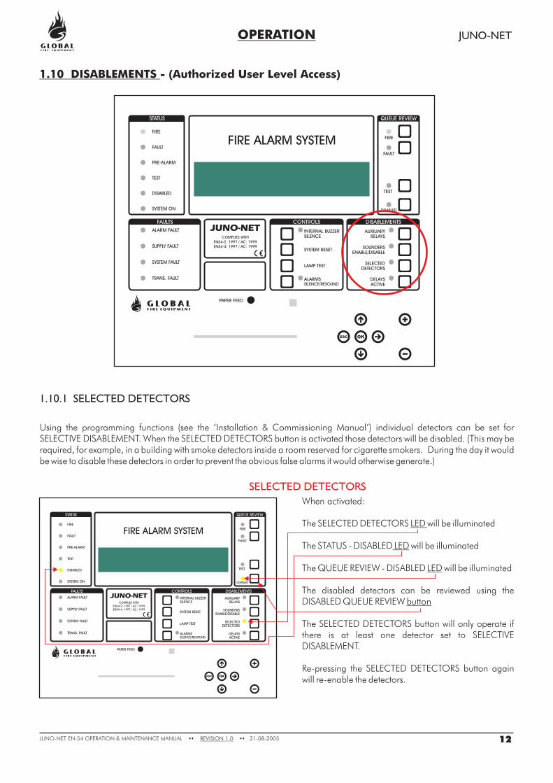
1.10 DISABLEMENTS - (Authorized User Level Access)
1.10.1 SELECTED DETECTORS
SELECTED DETECTORS
When activated:
The SELECTED DETECTORS will be illuminated
The STATUS - DISABLED will be illuminated
The QUEUE REVIEW - DISABLED will be illuminated
The disabled detectors can be reviewed using theDISABLED QUEUE REVIEW
The SELECTED DETECTORS button will only operate ifthere is at least one detector set to SELECTIVEDISABLEMENT.
Re-pressing the SELECTED DETECTORS button againwill re-enable the detectors.
LED
LED
LED
button
Using the programming functions (see the ‘Installation & Commissioning Manual’) individual detectors can be set forSELECTIVE DISABLEMENT. When the SELECTED DETECTORS button is activated those detectors will be disabled. (This may berequired, for example, in a building with smoke detectors inside a room reserved for cigarette smokers. During the day it wouldbe wise to disable these detectors in order to prevent the obvious false alarms it would otherwise generate.)
12JUNO-NET EN-54 MAINTENANCE MANUAL 21-08-2005REVISION 1.0OPERATION & �� ��
FIRE
FAULT
PRE-ALARM
TEST
DISABLED
SYSTEM ON
ALARM FAULT
SUPPLY FAULT
SYSTEM FAULT
TRANS. FAULT
PAPER FEED
LAMP TEST
SYSTEM RESET
INTERNAL BUZZER
SILENCE
DISABLED
TEST
FAULT
FIRE
AUXILIARY
RELAYS
SOUNDERS
ENABLE/DISABLE
SELECTED
DETECTORS
DELAYS
ACTIVE
STATUS
FAULTS CONTROLS DISABLEMENTS
QUEUE REVIEW
SILENCE/RESOUND
ALARMS
ESC OK
FIRE ALARM SYSTEM
COMPLIES WITH
-2: 1997 / AC: 1999
EN54-4: 1997 / AC: 1999
EN54
FIRE
FAULT
PRE-ALARM
TEST
DISABLED
SYSTEM ON
ALARM FAULT
SUPPLY FAULT
SYSTEM FAULT
TRANS. FAULT
PAPER FEED
LAMP TEST
SYSTEM RESET
INTERNAL BUZZER
SILENCE
DISABLED
TEST
FAULT
FIRE
AUXILIARY
RELAYS
SOUNDERS
ENABLE/DISABLE
SELECTED
DETECTORS
DELAYS
ACTIVE
STATUS
FAULTS CONTROLS DISABLEMENTS
QUEUE REVIEW
SILENCE/RESOUND
ALARMS
ESC OK
FIRE ALARM SYSTEM
COMPLIES WITH
-2: 1997 / AC: 1999
EN54-4: 1997 / AC: 1999
EN54
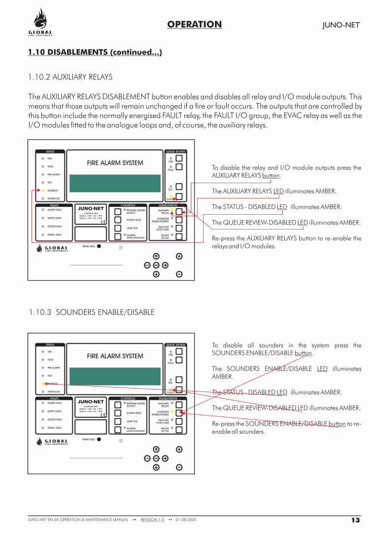
To disable press the.
The illuminatesAMBER.
The STATUS - DISABLED illuminates AMBER.
Re-press the to re-enable all sounders.
button
LED
LED
button
all sounders in the systemSOUNDERS ENABLE/DISABLE
SOUNDERS ENABLE/DISABLE
SOUNDERS ENABLE/DISABLE
The QUEUE REVIEW-DISABLED LED illuminates AMBER.
To disable the relay and I/O module outputs press theAUXILIARY RELAYS .
The AUXILIARY RELAYS illuminates AMBER.
The STATUS - DISABLED illuminates AMBER.
Re-press the AUXILIARY RELAYS button to re-enable therelays and I/O modules.
button
LED
LED
The QUEUE REVIEW-DISABLED illuminates AMBER.LED
OPERATION JUNO-NET
1.10 DISABLEMENTS (continued...)
1.10.2 AUXILIARY RELAYS
1.10.3 SOUNDERS ENABLE/DISABLE
The AUXILIARY RELAYS DISABLEMENT button enables and disables all relay and I/O module outputs. Thismeans that those outputs will remain unchanged if a fire or fault occurs. The outputs that are controlled bythis button include the normally energised FAULT relay, the FAULT I/O group, the EVAC relay as well as theI/O modules fitted to the analogue loops and, of course, the auxiliary relays.
13JUNO-NET EN-54 MAINTENANCE MANUAL 21-08-2005REVISION 1.0OPERATION & �� ��
FIRE
FAULT
PRE-ALARM
TEST
DISABLED
SYSTEM ON
ALARM FAULT
SUPPLY FAULT
SYSTEM FAULT
TRANS. FAULT
PAPER FEED
LAMP TEST
SYSTEM RESET
INTERNAL BUZZER
SILENCE
DISABLED
TEST
FAULT
FIRE
AUXILIARY
RELAYS
SOUNDERS
ENABLE/DISABLE
SELECTED
DETECTORS
DELAYS
ACTIVE
STATUS
FAULTS CONTROLS DISABLEMENTS
QUEUE REVIEW
SILENCE/RESOUND
ALARMS
ESC OK
FIRE ALARM SYSTEM
COMPLIES WITH
-2: 1997 / AC: 1999
EN54-4: 1997 / AC: 1999
EN54
FIRE
FAULT
PRE-ALARM
TEST
DISABLED
SYSTEM ON
ALARM FAULT
SUPPLY FAULT
SYSTEM FAULT
TRANS. FAULT
PAPER FEED
LAMP TEST
SYSTEM RESET
INTERNAL BUZZER
SILENCE
DISABLED
TEST
FAULT
FIRE
AUXILIARY
RELAYS
SOUNDERS
ENABLE/DISABLE
SELECTED
DETECTORS
DELAYS
ACTIVE
STATUS
FAULTS CONTROLS DISABLEMENTS
QUEUE REVIEW
SILENCE/RESOUND
ALARMS
ESC OK
FIRE ALARM SYSTEM
COMPLIES WITH
-2: 1997 / AC: 1999
EN54-4: 1997 / AC: 1999
EN54
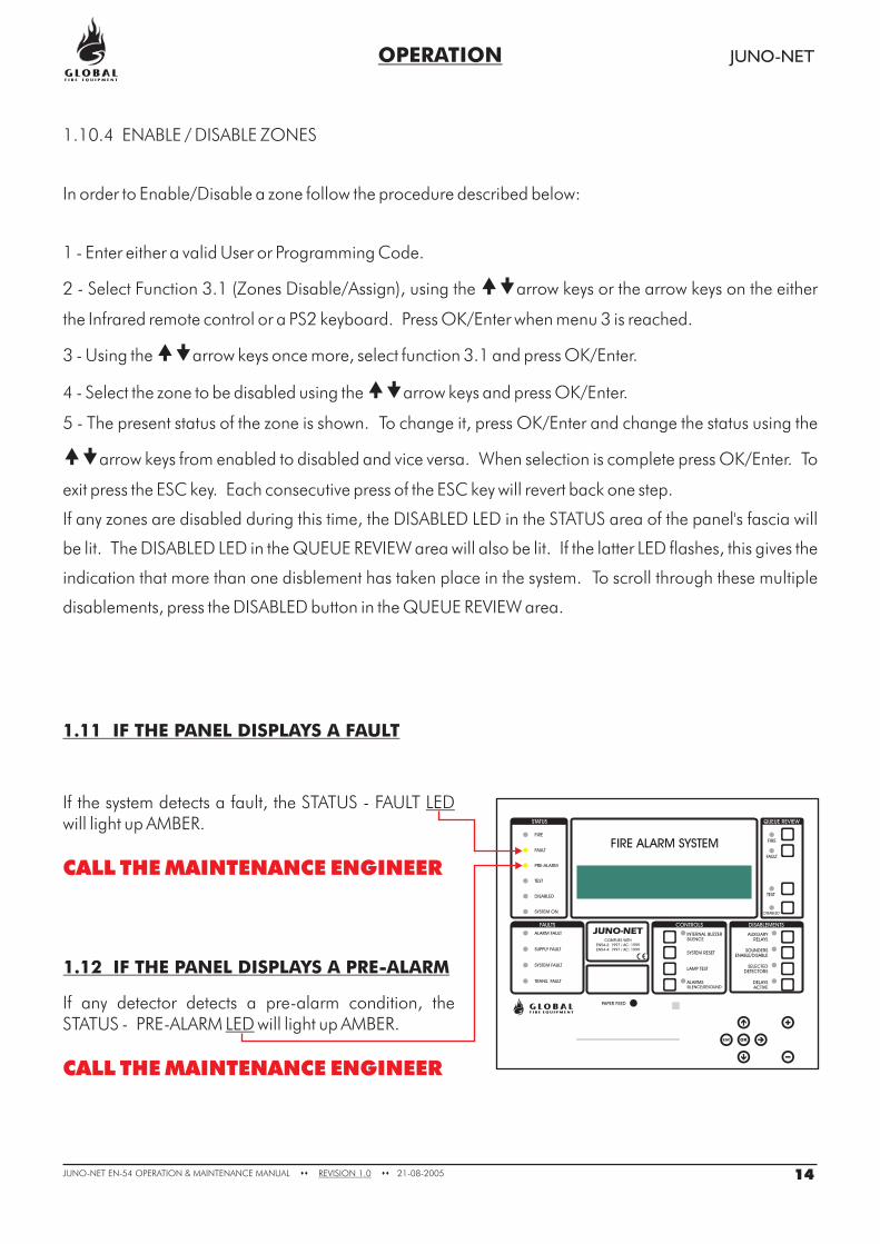
If any detector detects a pre-alarm condition, theSTATUS - PRE-ALARM will light up AMBER.LED
CALL THE MAINTENANCE ENGINEER
1.12 IF THE PANEL DISPLAYS A PRE-ALARM
If the system detects a fault, the STATUS - FAULTwill light up AMBER.
LED
CALL THE MAINTENANCE ENGINEER
OPERATION JUNO-NET
1.11 IF THE PANEL DISPLAYS A FAULT
14JUNO-NET EN-54 MAINTENANCE MANUAL 21-08-2005REVISION 1.0OPERATION & �� ��
1.10.4 ENABLE / DISABLE ZONES
In order to Enable/Disable a zone follow the procedure described below:
1 - Enter either a valid User or Programming Code.
2 - Select Function 3.1 (Zones Disable/Assign), using the arrow keys or the arrow keys on the either
the Infrared remote control or a PS2 keyboard. Press OK/Enter when menu 3 is reached.
3 - Using the arrow keys once more, select function 3.1 and press OK/Enter.
4 - Select the zone to be disabled using the arrow keys and press OK/Enter.
5 - The present status of the zone is shown. To change it, press OK/Enter and change the status using the
arrow keys from enabled to disabled and vice versa. When selection is complete press OK/Enter. To
exit press the ESC key. Each consecutive press of the ESC key will revert back one step.
If any zones are disabled during this time, the DISABLED LED in the STATUS area of the panel's fascia will
be lit. The DISABLED LED in the QUEUE REVIEW area will also be lit. If the latter LED flashes, this gives the
indication that more than one disblement has taken place in the system. To scroll through these multiple
disablements, press the DISABLED button in the QUEUE REVIEW area.
��
��
��
��
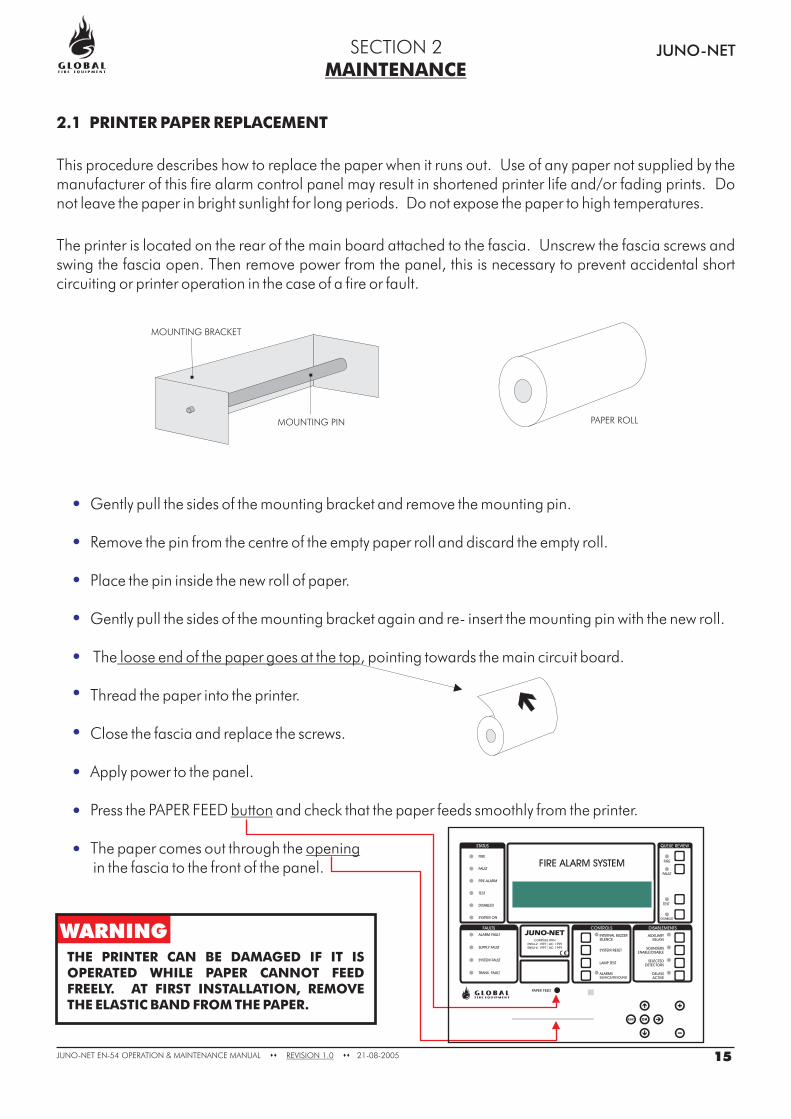
2.1 PRINTER PAPER REPLACEMENT
This procedure describes how to replace the paper when it runs out. Use of any paper not supplied by themanufacturer of this fire alarm control panel may result in shortened printer life and/or fading prints. Donot leave the paper in bright sunlight for long periods. Do not expose the paper to high temperatures.
The printer is located on the rear of the main board attached to the fascia. Unscrew the fascia screws andswing the fascia open. Then remove power from the panel, this is necessary to prevent accidental shortcircuiting or printer operation in the case of a fire or fault.
MAINTENANCEJUNO-NETSECTION 2
Gently pull the sides of the mounting bracket and remove the mounting pin.
Remove the pin from the centre of the empty paper roll and discard the empty roll.
Place the pin inside the new roll of paper.
Gently pull the sides of the mounting bracket again and re- insert the mounting pin with the new roll.
The , pointing towards the main circuit board.
Thread the paper into the printer.
Close the fascia and replace the screws.
Press the PAPER FEED and check that the paper feeds smoothly from the printer.
The paper comes out through thein the fascia to the front of the panel.
loose end of the paper goes at the top
button
opening
Apply power to the panel.
MOUNTING BRACKET
MOUNTING PIN PAPER ROLL
THE PRINTER CAN BE DAMAGED IF IT ISOPERATED WHILE PAPER CANNOT FEEDFREELY. AT FIRST INSTALLATION, REMOVETHE ELASTIC BAND FROM THE PAPER.
WARNING
15JUNO-NET EN-54 MAINTENANCE MANUAL 21-08-2005REVISION 1.0OPERATION & �� ��
FIRE
FAULT
PRE-ALARM
TEST
DISABLED
SYSTEM ON
ALARM FAULT
SUPPLY FAULT
SYSTEM FAULT
TRANS. FAULT
PAPER FEED
LAMP TEST
SYSTEM RESET
INTERNAL BUZZER
SILENCE
DISABLED
TEST
FAULT
FIRE
AUXILIARY
RELAYS
SOUNDERS
ENABLE/DISABLE
SELECTED
DETECTORS
DELAYS
ACTIVE
STATUS
FAULTS CONTROLS DISABLEMENTS
QUEUE REVIEW
SILENCE/RESOUND
ALARMS
ESC OK
FIRE ALARM SYSTEM
COMPLIES WITH
-2: 1997 / AC: 1999
EN54-4: 1997 / AC: 1999
EN54
DISPLAY
SIM CARD CONNECTOR
JUNO-NET MOTHERBOARD (BACK VIEW)
MAINTENANCE JUNO-NET
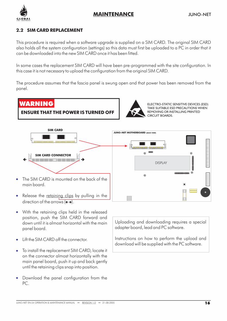
2.2 SIM CARD REPLACEMENT
This procedure is required when a software upgrade is supplied on a SIM CARD. The original SIM CARDalso holds all the system configuration (settings) so this data must first be uploaded to a PC in order that itcan be downloaded into the new SIM CARD once it has been fitted.
In some cases the replacement SIM CARD will have been pre-programmed with the site configuration. Inthis case it is not necessary to upload the configuration from the original SIM CARD.
The procedure assumes that the fascia panel is swung open and that power has been removed from thepanel.
WARNING
ENSURE THAT THE POWER IS TURNED OFF
SIM CARD
The SIM CARD is mounted on the back of themain board.
Release the by pulling in the
direction of the arrows ( ).
With the retaining clips held in the releasedposition, push the SIM CARD forward anddown until it is almost horizontal with the mainpanel board.
Lift the SIM CARD off the connector.
To install the replacement SIM CARD, locate iton the connector almost horizontally with themain panel board, push it up and back gentlyuntil the retaining clips snap into position.
Download the panel configuration from thePC.
retaining clips
Uploading and downloading requires a specialadapter board, lead and PC software.
Instructions on how to perform the upload anddownload will be supplied with the PC software.
ELECTRO-STATIC SENSITIVE DEVICES (ESD)
TAKE SUITABLE ESD PRECAUTIONS WHEN
REMOVING OR INSTALLING PRINTED
CIRCUIT BOARDS.
16JUNO-NET EN-54 MAINTENANCE MANUAL 21-08-2005REVISION 1.0OPERATION & �� ��
MAINTENANCE JUNO-NET
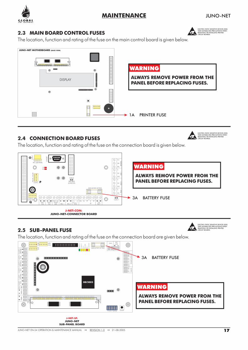
2.3 MAIN BOARD CONTROL FUSES
The location, function and rating of the fuse on the main control board is given below.
2.4 CONNECTION BOARD FUSES
The location, function and rating of the fuse on the connection board is given below.
2.5 SUB-PANEL FUSE
The location, function and rating of the fuse on the connection board are given below.
DISPLAY
JUNO-NET MOTHERBOARD (BACK VIEW)
1A PRINTER FUSE
3A BATTERY FUSE
WARNING
WARNING
WARNING
ALWAYS REMOVE POWER FROM THEPANEL BEFORE REPLACING FUSES.
ALWAYS REMOVE POWER FROM THEPANEL BEFORE REPLACING FUSES.
ALWAYS REMOVE POWER FROM THEPANEL BEFORE REPLACING FUSES.
ELECTRO-STATIC SENSITIVE DEVICES (ESD)TAKE SUITABLE ESD PRECAUTIONS WHENREMOVING OR INSTALLING PRINTEDCIRCUIT BOARDS.
ELECTRO-STATIC SENSITIVE DEVICES (ESD)TAKE SUITABLE ESD PRECAUTIONS WHENREMOVING OR INSTALLING PRINTEDCIRCUIT BOARDS.
ELECTRO-STATIC SENSITIVE DEVICES (ESD)TAKE SUITABLE ESD PRECAUTIONS WHENREMOVING OR INSTALLING PRINTEDCIRCUIT BOARDS.
J-NET-SP:
JUNO-NETSUB-PANEL BOARD
3A BATTERY FUSE
J-NET-CON:JUNO-NET-CONNECTOR BOARD
123456
ON
SND
R1
SND
R2
LOO
P1
OU
TLO
OP
2O
UT
LOO
P3
OU
TLO
OP
1RETU
RN
LOO
P2
RETU
RN
LOO
P3
RETU
RN
AU
XPS
POW
ER
SUPP
LYIN
0V
0V
0V
24
V2
8V
28
VM
ON
ETH
BATT24V
EVAC
CO
MM
SO
K
CO
MM
SFLT
PRE-A
LARM
FAU
LT
5VO
LTFA
ULT
FIRE
PANELNO SILENCEAC
N4 MPX
CN5
CN
3
H8/3003
MAX 3A FAST ACTING
17JUNO-NET EN-54 MAINTENANCE MANUAL 21-08-2005REVISION 1.0OPERATION & �� ��
AUX 1PSU
CON 2ZONE LED
CON 5FIRE BRIG.
ACKNOWL.
INT. SUB PANEL
FIB
.OPT
./
RS-4
85
CO
N1
TXRX
LOA
DER
CON 6
AUX 2PSU BELL 1 BELL 2
24vBATT
PAL
NO
NO
FIR
NC
NC
NC
REPE
ATS
AU
X2
FAU
LTA
UX
1
FLT
C
C
C
EVACZONEMPX
OUT PF E SF24v0v 0v0v
MAX 3A FAST ACTING
CON 7
O
P
Q
MAINTENANCE JUNO-NET
2.6 BATTERY VOLTAGE AND CHARGER CHECKS
On the main panel and sub-panels (if fitted) measure the battery voltage. This should be 28.5V +/- 0.2V.Switch off the primary supply and check that the battery voltage does not drop significantly. Carry out atest on a detector or manual callpoint with the primary supply disconnected to ensure that the batteries arehealthy.
NOTE: BATTERIES MUST BE REPLACED PERIODICALLY IN ACCORDANCE WITH THEMANUFACTURER'S RECOMMENDATION. ALWAYS USE SEALED LEAD ACID BATTERIES.
18JUNO-NET EN-54 MAINTENANCE MANUAL 21-08-2005REVISION 1.0OPERATION & �� ��
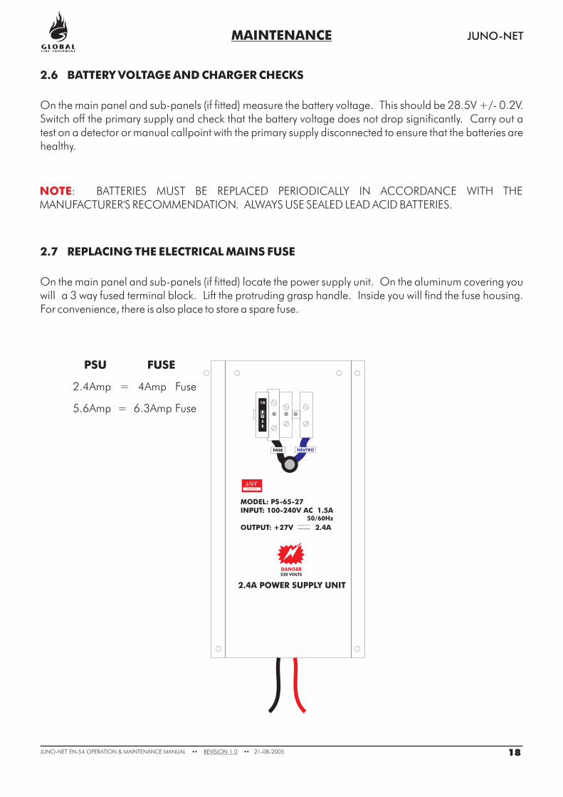
2.7 REPLACING THE ELECTRICAL MAINS FUSE
On the main panel and sub-panels (if fitted) locate the power supply unit. On the aluminum covering youwill a 3 way fused terminal block. Lift the protruding grasp handle. Inside you will find the fuse housing.For convenience, there is also place to store a spare fuse.
NEUTROFASE
1A
FUSE
MEANWELL
MODEL: PS-65-27INPUT: 100-240V AC 1.5A
OUTPUT: +27V 2.4A
50/60Hz
DANGER220 VOLTS
2.4A POWER SUPPLY UNIT
2.4Amp = 4Amp Fuse
5.6Amp = 6.3Amp Fuse
PSU FUSE
MAINTENANCE JUNO-NET
2.8 USE OF PROGRAMMING FUNCTIONS FOR MAINTENANCE
The following programming functions can be used to check that the panel is operating correctly.
Note that to use these functions the installer needs to have granted ‘User Access’ to the followingfunctions. By default, access is denied.
Entry to Programming Mode is covered in the section 2.8.
1-1 Display Historic Log
1-2 Print Historic Log Entries
1-3 Clear Historic Log
1-4 Print Loop/Device Set-up
The panel logs all events in an internal event log. It can store a rolling 2000 entries. When it is full the latestentry is added and the oldest entry discarded.
Help is automatically displayed on entry to the function because it is not possible to display a log entry andhelp at the same time.
To select a specific entry, input the number and then press ENTER.
Select which entries you wish to print and press ENTER.
If the printer is already in use it is necessary to wait until the printer is free before starting a new print job.
If you wish to stop a printout enter the function again and you will be given the option of canceling theprintout.
This function cannot be accessed remotely (from a Repeater or the PC Graphics Interface).
Nothing will be printed if the printer is disabled by (function 8-4-3).
Note that once the log is full the log entry number (0001 - 2000) will change for each logged event but logentry 0001 will be the oldest entry and 2000 will be the most recent.
Clears the Historic Log.
Prints all the device information for the specified Analogue Loop. The information printed includes thedevice address, type, zone, text label and whether it is currently disabled.
If the printer is already in use it is necessary to wait until the printer is free before starting a new print job.
If you wish to stop a printout enter the function again and you will be given the option of canceling theprintout.
This function cannot be accessed remotely (from the PC Graphics software or a Repeater).
Nothing will be printed if the printer is disabled by (function 8-4-3).
19JUNO-NET EN-54 MAINTENANCE MANUAL 21-08-2005REVISION 1.0OPERATION & �� ��
MAINTENANCE JUNO-NET
1-5 Read/Clear Autostart Count
7-1 Device Count, Type & Value
7-2 Test Sounders
Main Panel
Standard Sub-panels
Integrated Sub-panels
Every time the Main Panel has a Master Reset or it’s power is cycled the Autostart count is incremented.SYSTEM RESETs from the front panel button do not increment the Autostart count.
Use this function to check that all Sub-panels are present and that all devices are present.
Use +/- to select the Analogue Loop number and 0-9 and to select the device address on thatloop.
This function is also useful to confirm the address of the various different types of devices connected to theAnalogue Loops.
Note that in Installation Mode all information is live i.e. the count of devices will change as the panellearns and device types will be updated if they change. In Active Mode only the device value is live.
Use this function to test the audibility of the sounders in a more comfortable manner than pressingSOUND ALARMS.
The Main Panel Conventional Sounders will sound for 1 second then be silenced for 9 seconds.
Conventional Sounders and Loop Sounders are operated for 1 second then silenced for 9 seconds.
Conventional Sounders and Loop Sounders are operated for 1 second then silenced for 9 seconds.
Conventional Sounder operation for a Repeater Integrated Sub-panel will be synchronized to the LoopSounder operation.
20JUNO-NET EN-54 MAINTENANCE MANUAL 21-08-2005REVISION 1.0OPERATION & �� ��
MAINTENANCE JUNO-NET
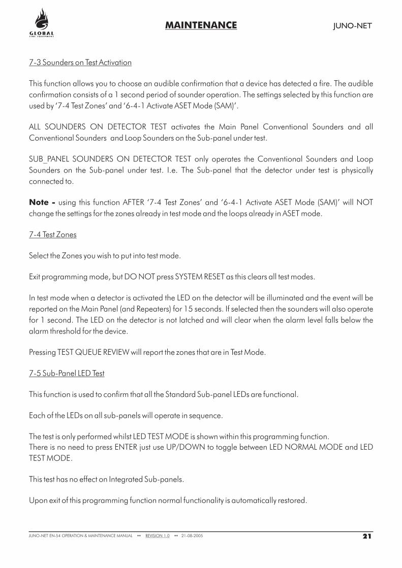
7-3 Sounders on Test Activation
7-4 Test Zones
7-5 Sub-Panel LED Test
This function allows you to choose an audible confirmation that a device has detected a fire. The audible
confirmation consists of a 1 second period of sounder operation. The settings selected by this function are
used by ‘7-4 Test Zones’ and ‘6-4-1 Activate ASET Mode (SAM)’.
ALL SOUNDERS ON DETECTOR TEST activates the Main Panel Conventional Sounders and all
Conventional Sounders and Loop Sounders on the Sub-panel under test.
SUB_PANEL SOUNDERS ON DETECTOR TEST only operates the Conventional Sounders and Loop
Sounders on the Sub-panel under test. I.e. The Sub-panel that the detector under test is physically
connected to.
using this function AFTER ‘7-4 Test Zones’ and ‘6-4-1 Activate ASET Mode (SAM)’ will NOT
change the settings for the zones already in test mode and the loops already in ASET mode.
Select the Zones you wish to put into test mode.
Exit programming mode, but DO NOT press SYSTEM RESET as this clears all test modes.
In test mode when a detector is activated the LED on the detector will be illuminated and the event will be
reported on the Main Panel (and Repeaters) for 15 seconds. If selected then the sounders will also operate
for 1 second. The LED on the detector is not latched and will clear when the alarm level falls below the
alarm threshold for the device.
Pressing TEST QUEUE REVIEW will report the zones that are in Test Mode.
This function is used to confirm that all the Standard Sub-panel LEDs are functional.
Each of the LEDs on all sub-panels will operate in sequence.
The test is only performed whilst LED TEST MODE is shown within this programming function.
There is no need to press ENTER just use UP/DOWN to toggle between LED NORMAL MODE and LED
TEST MODE.
This test has no effect on Integrated Sub-panels.
Upon exit of this programming function normal functionality is automatically restored.
Note -
21JUNO-NET EN-54 MAINTENANCE MANUAL 21-08-2005REVISION 1.0OPERATION & �� ��
MAINTENANCE JUNO-NET
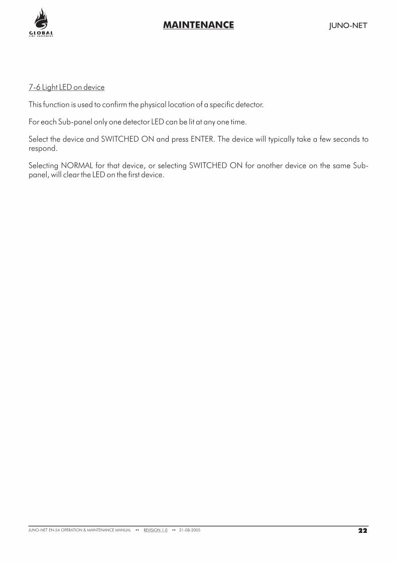
7-6 Light LED on device
This function is used to confirm the physical location of a specific detector.
For each Sub-panel only one detector LED can be lit at any one time.
Select the device and SWITCHED ON and press ENTER. The device will typically take a few seconds torespond.
Selecting NORMAL for that device, or selecting SWITCHED ON for another device on the same Sub-panel, will clear the LED on the first device.
22JUNO-NET EN-54 MAINTENANCE MANUAL 21-08-2005REVISION 1.0OPERATION & �� ��
MAINTENANCE JUNO-NET
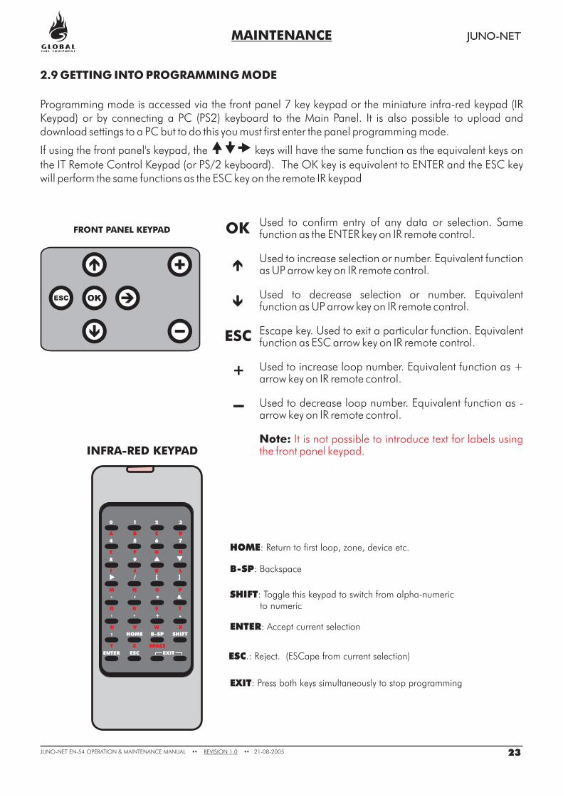
Programming mode is accessed via the front panel 7 key keypad or the miniature infra-red keypad (IRKeypad) or by connecting a PC (PS2) keyboard to the Main Panel. It is also possible to upload anddownload settings to a PC but to do this you must first enter the panel programming mode.
If using the front panel's keypad, the keys will have the same function as the equivalent keys on
the IT Remote Control Keypad (or PS/2 keyboard). The OK key is equivalent to ENTER and the ESC keywill perform the same functions as the ESC key on the remote IR keypad
���
INFRA-RED KEYPAD
0
A
4
E
8
I
1
B
5
F
9
J
2
C
6
G
K
3
D
7
H
L
M N
/ [ ]
. ,
' " + -
:
* &
O P
Q R S T
U V W X
Y
HOME SHIFT
ENTER
B-SP
Z SPACE
ESC EXIT
HOME: Return to first loop, zone, device etc.
ENTER: Accept current selection
B-SP: Backspace
ESC.: Reject. (ESCape from current selection)
EXIT: Press both keys simultaneously to stop programming
SHIFT: Toggle this keypad to switch from alpha-numericto numeric
2.9 GETTING INTO PROGRAMMING MODE
23JUNO-NET EN-54 MAINTENANCE MANUAL 21-08-2005REVISION 1.0OPERATION & �� ��
FRONT PANEL KEYPAD
ESC OK
Used to confirm entry of any data or selection. Samefunction as the ENTER key on IR remote control.
Used to increase selection or number. Equivalent functionas UP arrow key on IR remote control.
Used to decrease selection or number. Equivalentfunction as UP arrow key on IR remote control.
Escape key. Used to exit a particular function. Equivalentfunction as ESC arrow key on IR remote control.
Used to increase loop number. Equivalent function as +arrow key on IR remote control.
Used to decrease loop number. Equivalent function as -arrow key on IR remote control.
Note: It is not possible to introduce text for labels usingthe front panel keypad.
OK
ESC
+
-
MAINTENANCE JUNO-NET
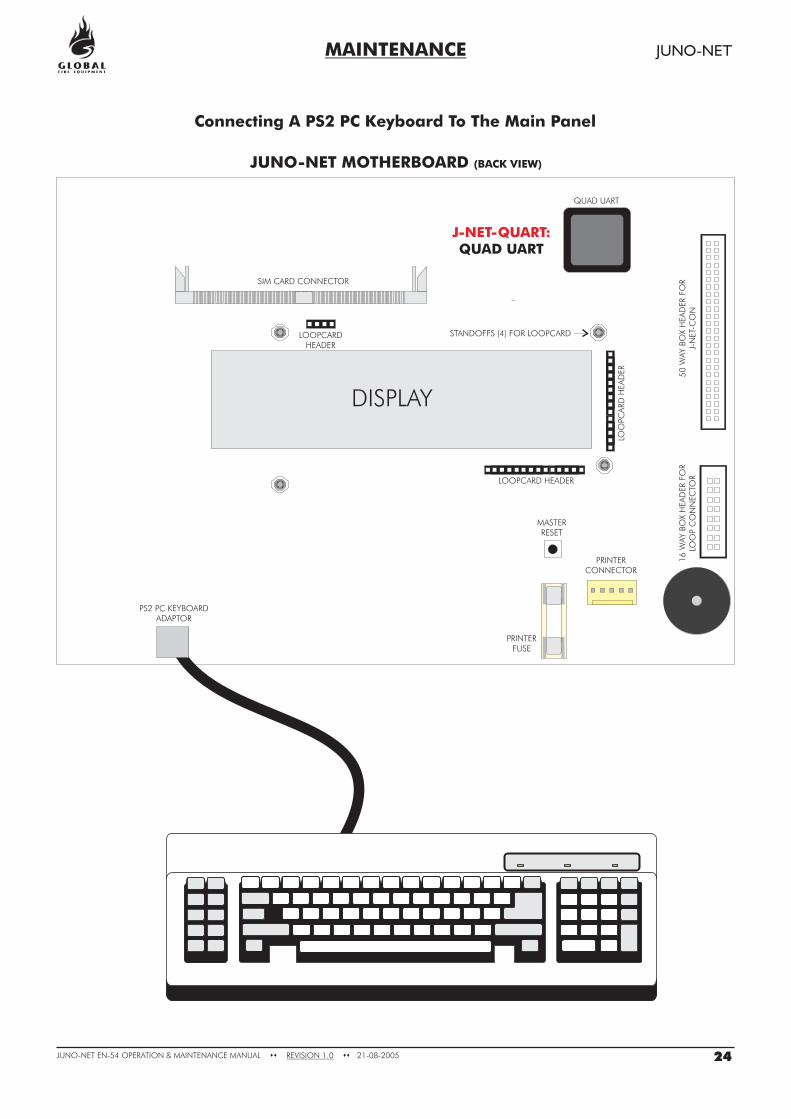
Connecting A PS2 PC Keyboard To The Main Panel
DISPLAY
LOOPCARDHEADER
LOOPCARD HEADER
MASTERRESET
PRINTERCONNECTOR
PRINTERFUSE
PS2 PC KEYBOARDADAPTOR
STANDOFFS (4) FOR LOOPCARD
SIM CARD CONNECTOR
QUAD UART
50
WAY
BO
XH
EA
DER
FOR
J-N
ET-
CO
N1
6W
AY
BO
XH
EA
DER
FOR
LOO
PC
ON
NEC
TOR
LOO
PCA
RD
HEA
DER
JUNO-NET MOTHERBOARD (BACK VIEW)
J-NET-QUART:QUAD UART
24JUNO-NET EN-54 MAINTENANCE MANUAL 21-08-2005REVISION 1.0OPERATION & �� ��
The IR Keypad is typically the most convenient method to program the system. The sensor for the IRKeypad is just below the SOUND ALARMS button on the Main Panel and on a Repeater. Each time akey is pressed on the IR Keypad the Main Panel will beep.
If no beeps are audible then check the batteries in the IR Keypad.
The IR Keypad uses 2 x AAA batteries.
To access the characters in , first press the SHIFT KEY. To return to the characters in BLACK pressthe SHIFT KEY again.
Each time a key press is received by the panel the panel emits a beep. The beeps when SHIFT is onare of a higher pitch than when SHIFT is off.
0-9 are used to input numbersand are used to select items
B-SP and are often used to change fields (move the cursor)+/- are often used to select the loopENTER is used to select items and to store changesESC is used to abort changes and exitHOME is often used to go back to the start of a function
Pressing both EXIT keys exits programming mode.
Where possible help is displayed automatically. However additional help is sometimes available if youpress the help key ‘:’ the colon.
The first press will display help for 7 seconds, a second press will ensure the help is displayed for 20seconds. Pressing any key whilst help is displayed will clear the help but this key press will be ignored.
The IR Keypad Keys
Help
RED
MAINTENANCE JUNO-NET
25JUNO-NET EN-54 MAINTENANCE MANUAL 21-08-2005REVISION 1.0OPERATION & �� ��
Logging In
To enter programming mode you need to log in.
The Main Panel must be powered up and must have initialised itself i.e. NOT be showing the‘INITIALISING’ message.
Press ENTER on the Panel Keypad, IR Keypad (or keyboard). You must now input your uniquecustomer access code (supplied with the panel). You have unlimited attempts but if code entry is notstarted within 10 seconds then the panel will revert back to it’s default screen. While entering the codeyou are allowed up to 5 seconds between key presses.
The programming functions are arranged using a menu system.
To select a function or sub-menu use either and ENTER or 0-9 and ENTER.
HOME takes you to "1-Review".ESC takes you up a menu level.
Any number presses (0-9) will append a digit to what you see unless :
1) You are at the very top (1- Review) then the first press selects the first digit.2) You are at the bottom then the press replaces the last digit.
The top level menus are:
1 Review Historic Log2 Text Descriptions & Names3 Zones - Disable & Assign4 Sounders - Disable & Assign5 Input/Output - Disable & Assign6 Device Set-up7 Monitor Device Counts & Test8 General
Most functions operate in a consistent manner using the standard keys. The item that is beingchanged is usually highlighted with a flashing cursor.
Function Selection
� �
MAINTENANCE JUNO-NET
26JUNO-NET EN-54 MAINTENANCE MANUAL 21-08-2005REVISION 1.0OPERATION & �� ��
MAINTENANCE JUNO-NET
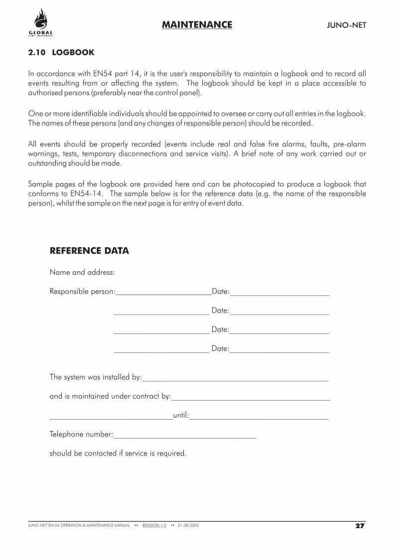
2.10 LOGBOOK
In accordance with EN54 part 14, it is the user's responsibility to maintain a logbook and to record allevents resulting from or affecting the system. The logbook should be kept in a place accessible toauthorised persons (preferably near the control panel).
One or more identifiable individuals should be appointed to oversee or carry out all entries in the logbook.The names of these persons (and any changes of responsible person) should be recorded.
All events should be properly recorded (events include real and false fire alarms, faults, pre-alarmwarnings, tests, temporary disconnections and service visits). A brief note of any work carried out oroutstanding should be made.
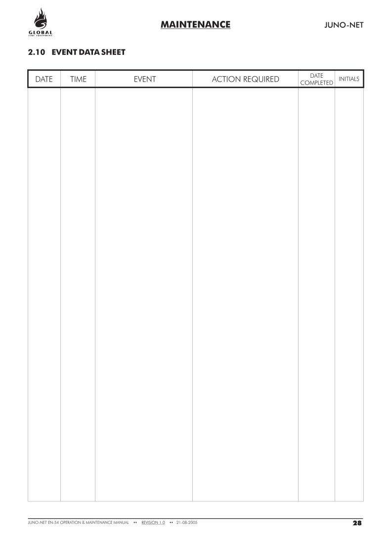
Sample pages of the logbook are provided here and can be photocopied to produce a logbook thatconforms to EN54-14. The sample below is for the reference data (e.g. the name of the responsibleperson), whilst the sample on the next page is for entry of event data.
REFERENCE DATA
Name and address:
Responsible person: Date:_________________________
________________________ Date:_________________________
________________________ Date:_________________________
________________________ Date:_________________________
The system was installed by:_______________________________________________
and is maintained under contract by:________________________________________
_______________________________until:___________________________________
Telephone number:____________________________________
should be contacted if service is required.
27JUNO-NET EN-54 MAINTENANCE MANUAL 21-08-2005REVISION 1.0OPERATION & �� ��
MAINTENANCE JUNO-NET
2.10 EVENT DATA SHEET
DATE TIME EVENT INITIALSACTION REQUIREDDATE
COMPLETED
28JUNO-NET EN-54 MAINTENANCE MANUAL 21-08-2005REVISION 1.0OPERATION & �� ��