
EN User Manual - Esprit Tech/Model 1.321.729.4287
42
EN ® User Manual EN
Transcript of EN User Manual - Esprit Tech/Model 1.321.729.4287

EN®
User ManualEN
EN
1. Introduction ..................................................................................... 3 EN
1.1 Attributes ................................................................................... 4 EN
1.1.1 Central Box 100 ............................................................... 4 EN
1.1.2 Central Box 210/220 ...................................................... 4 EN
2. Description ........................................................................................ 5 EN
2.1 Central Box 210/220 ................................................................ 5 EN
2.1.1 Central Box 210 ............................................................... 5EN
2.1.2 Central Box 220 ............................................................... 6EN
2.2. Central Box 100 ....................................................................... 8 EN
2.3 Magnetic switch ( Central Box 210/220 ) ............................ 9 EN
3. Connection ..................................................................................... 10 EN
3.1 Power supply of Central Box 210/220 ................................ 10 EN
3.2 Power supply of Central Box 100 ......................................... 12 EN
3.3 Overload protection of servos ............................................ 14 EN
3.4 Connecting Central Box – EX Bus ........................................ 15 EN
3.4.1 Central Box 210/220 .................................................... 15EN
3.4.2 Connecting Central Box 100 ....................................... 15EN
3.5 Alternative functions – digital input .................................. 17 EN
3.6 Alternative functions - digital output ............................... 18 EN
3.7 OUT/IN pin (Central Box 100) .............................................. 19 EN
4. Configuration via JETIBOX ....................................................... 21 EN
4.1 Actual values .......................................................................... 22 EN
1 EN

EN
4.2 Minimum / Maximum values ............................................. 22 EN
4.3 Setting ..................................................................................... 23EN
4.4 Out Pin Set ............................................................................... 25 EN
4.5 Alarms .................................................................................... 26 EN
4.6 Service information .............................................................. 27 EN
5. Configuration via the DC/DS transmitter ............................. 28 EN
5.1 Settings .................................................................................... 29 EN
5.2 Alternate functions of pins .................................................. 30 EN
5.3 Servo Fail-Safe ....................................................................... 31 EN
5.4 Servo Output Mapping ....................................................... 32 EN
5.5 Telemetry ............................................................................... 33 EN
5.6 Telemetry Min/Max .............................................................. 33 EN
5.7 Reset to factory settings ...................................................... 34 EN
6. Firmware update ........................................................................... 35 EN
7. Safety precautions for working with magnets ................... 36 EN
8. Technical specifications of the Central Box .......................... 37 EN
9. Warranty, service and the technical support ....................... 38 EN
2 EN

EN
1 Introduction ENGLISH
The Central Box is a switchboard designed for the complete management of servos in a model with an emphasis on safety. The Central Box 100 and 220 have a unique design that provides overload protection at each servo output. The Central Box 210 offers maximal unreduced power for each servo (servo outputs do not have overload protection). The Central Box can manage up to two batteries and fully supports the JETI EX telemetry system. Up to three receivers with serial (PPM, EX Bus, S.BUS) output can be connected to the Central Box 210 and 220. With JETI DC/DS transmitter, the full potential of the Central Box can be used, such as an easy way to configure the Central Box, EX telemetry, and very fast servo response.
3 EN

EN
1.1 Attributes1.1.1 Central Box 100
• Overload protection on each channel• Possibility to connect up to 2 receivers with serial interface PPM, EX Bus)• Built-in Expander function• 1x MPX battery input connector• 100Hz mode of servo outputs (10ms period)• Supports EX telemetry (voltage, current, capacity, and temperature measurement, overload indication, ...)• Easy settings changes via DC/DS transmitter• Firmware updates by user• Suitable for use with high voltage (HV) servos• Compact size for easy installation• Each output is individually configurable (channel assignment,
trim, reverse, ATV)
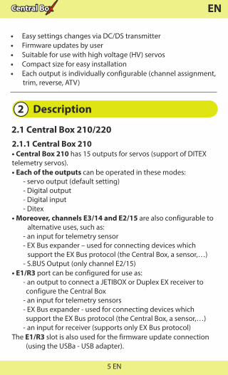
1.1.2 Central Box 210/220
• Central Box 210 has unreduced power for each servo (without fuses)
• Central Box 220 has overload protection on each channel (4 outputs for high-torque servos and 11 outputs for standard servos)
• Support of DITEX telemetry servos• Possibility to connect up to 3 receivers with serial interface to
(PPM, EX Bus, S.BUS)• Built-in Expander function for up to 3 sensors• Input for magnetic switch or RC switch• 2x MPX battery input connectors • 100Hz mode of servo outputs (10ms period)• Supports EX telemetry (voltage, current, capacity,
temperature measurement, …)
4 EN
EN
• Easy settings changes via DC/DS transmitter• Firmware updates by user• Suitable for use with high voltage (HV) servos• Compact size for easy installation• Each output is individually configurable (channel assignment,
trim, reverse, ATV)
2 Description
2.1.1 Central Box 210• Central Box 210 has 15 outputs for servos (support of DITEX telemetry servos).• Each of the outputs can be operated in these modes: - servo output (default setting) - Digital output - Digital input - Ditex• Moreover, channels E3/14 and E2/15 are also configurable to
alternative uses, such as: - an input for telemetry sensor - EX Bus expander – used for connecting devices which
support the EX Bus protocol (the Central Box, a sensor,…) - S.BUS Output (only channel E2/15)• E1/R3 port can be configured for use as: - an output to connect a JETIBOX or Duplex EX receiver to
configure the Central Box - an input for telemetry sensors - EX Bus expander - used for connecting devices which
support the EX Bus protocol (the Central Box, a sensor,…) - an input for receiver (supports only EX Bus protocol)The E1/R3 slot is also used for the firmware update connection
(using the USBa - USB adapter).
2.1 Central Box 210/220
5 EN
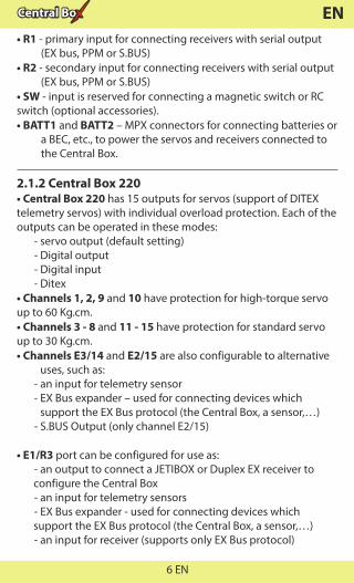
EN• R1 - primary input for connecting receivers with serial output
(EX bus, PPM or S.BUS)• R2 - secondary input for connecting receivers with serial output
(EX bus, PPM or S.BUS)• SW - input is reserved for connecting a magnetic switch or RCswitch (optional accessories).• BATT1 and BATT2 – MPX connectors for connecting batteries or
a BEC, etc., to power the servos and receivers connected to the Central Box.
2.1.2 Central Box 220• Central Box 220 has 15 outputs for servos (support of DITEX telemetry servos) with individual overload protection. Each of the outputs can be operated in these modes: - servo output (default setting) - Digital output - Digital input - Ditex• Channels 1, 2, 9 and 10 have protection for high-torque servo up to 60 Kg.cm. • Channels 3 - 8 and 11 - 15 have protection for standard servo up to 30 Kg.cm.• Channels E3/14 and E2/15 are also configurable to alternative
uses, such as: - an input for telemetry sensor - EX Bus expander – used for connecting devices which
support the EX Bus protocol (the Central Box, a sensor,…) - S.BUS Output (only channel E2/15)
• E1/R3 port can be configured for use as: - an output to connect a JETIBOX or Duplex EX receiver toconfigure the Central Box - an input for telemetry sensors - EX Bus expander - used for connecting devices whichsupport the EX Bus protocol (the Central Box, a sensor,…)
- an input for receiver (supports only EX Bus protocol)
6 EN

EN
Fig. 1: Central Box210/220 description
E1/E2
R1R2
E3
R3
22022022015 channel protected servo interface
RC Switch
Magnetic Switch
• The E1/R3 slot is also used for the firmware update connection (using the USBa - USB adapter).
• R1 - primary input for connecting receivers with serial output (EX bus, PPM or S.BUS)• R2 - secondary input for connecting receivers with serial output (EX bus, PPM or S.BUS)• SW - input is reserved for connecting a magnetic switch or RCswitch (optional accessories).• BATT1 and BATT2 – MPX connectors for connecting batteries or a BEC, etc., to power the servos and receivers connected to theCentral Box.
7 EN
EN
2.2 Central Box 100
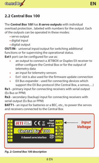
The Central Box 100 has 8 servo outputs with individual overload protection , labeled with numbers for the output. Each of the outputs can be operated in these modes: servo output • • digital input digital output •OUT/IN– universal input/output for switching additional functions or for supervising the operational status.Ext1 port can be configured for use as: • an output to connect a JETIBOX or Duplex EX receiver to either configure the Central Box or for the output of telemetry data • an input for telemetry sensors • Ext1 slot is also used for the firmware update connection • EX Bus expander - used for connecting devices which support the EX Bus protocol (the Central Box, a sensor,…)Rx1– primary input for connecting receivers with serial output (Ex Bus or PPM) Rx2– secondary (backup) input for connecting receivers with serial output (Ex Bus or PPM) BATT1– an input for batteries or a BEC, etc., to power the servos and receivers connected to the Central Box
7
Rx 1Rx 2Ext.
Out/In
BATT
88 channel servo interface
100100100
inputvoltage
4-14VInput
Voltage
Fig. 2: Central Box 100 description
8 EN

EN
2.3 Magnetic switch ( Central Box 210/220)The magnetic switch is used to turn the CB 210/220 ON or OFF . The magnetic switch is connected to Central Box 210/220 by the interconnection cable from normal Master port on the magnetic switch to a slot labeled "SW" on the Central Box 210/220. To turn on the Central Box using the magnetic switch it is necessary to hold the supplied magnet carrier (key) to the target so that the carrier (key) and the target on the magnetic switch are properly oriented (align the dots).
Green LED - flashing LED signals proper detection of the magnet key- steady LED signals “ON” state
When the magnet key is held to the target in the proper orientation, the green LED glow steadily after 1 second indicating that the electronic switch is turned “ON”.Switching „OFF” is done in a similar manner, when the magnet key is held to the target in the proper orientation, after 1 second, the green LED goes off and the system switches off.If the switch is not plugged in the Central Box, the Central Box is switched “ON”. The system remembers whether it has been switched “ON” or „OFF”. If the system is switched “ON” via the magnetic switch and then the power supply is disconnected, when the batteries are re-connected to the system automatically returns to the “ON” state. For safety
Fig. 3: Description of magnetic switch and the key
Key
Target
Led On
9 EN

EN
reasons, always switch the system off via magnetic switch before disconnecting the power batteries.When turning “ON”, connect the batteries first and then turn the system on via magnetic switch. Keep the same rule when switching off. First switch the system “OFF” via magnetic switch and then disconnect the batteries.
3 ConnectionThe Central Box is connected to the power supply, receiver, servos, controller/controllers and eventually sensors. Please follow the subsequent general guidelines about proper connection of the Central Box and these other components.
Central Box 100, Central Box 210 and 220 do not contain circuitry to stabilize or regulate voltage to the servos.The level of the input voltage is equal to the level of (output) supply voltage level to the servos. Be sure to match the proper type of servos with your selected power supply. Eg. when using 2 Li-xx cells without a regulator, it is necessary to use servos labeled “High Voltage”.
3.1 Power supply of Central Box 210/220The Central Box 210/220 can be powered from batteries which are directly connected, via a BEC or a regulator. When selecting power sources for the Central Box 220, be sure to follow the minimum power requirements. Together, both power supply methods must be able to supply a 15A continuous and 90A peak current. If the power supply is not strong enough, the overload protection feature of the Central Box 220 may not function correctly. The power batteries are connected to the Central Box 210/220 using MPX connectors. The Central Box 210/220 allows up to two batteries to be connected. During use, the power is actually supplied from the battery with the higher voltage. If the voltage is the same, the power can be used from both batteries at the same time. When the
10 EN

EN
Fig. 4: Example of the Central Box powered for use with standard servos (voltage range up to 6V)
voltage of the batteries is different, the power is not shared and each pack is isolated from each other. This allows you to use batteries of different capacity, number of cells, and chemistry type. If the power for the Central Box 210/220 is provided only from one battery, it can be connected via BATT1 or BATT2 input.
E1/E2
R1R2
E3
R3
22022022015 channel protected servo interface
RC SwitchMagnetic Switch
InputVoltage 6V
SERVO standardSE
RVO
stan
dard
Rsat2 (R2)
Rsat2 (R1)Ext.
Ext.
SATELLITE RECEIVER
I/0
E1
R 900 NGsat
Rsat900 NG (E1/R3)
E1/E2
The Central Box cannot be power supplied throug the servo outputs labeled Y1-15, sensor outputs labeled E1/R3 or receiver outputs labeled R1-2.
Caution:
11 EN

EN
Fig. 5: Example of the Central Box powered for use with HIGH Voltageservos
3.2 Power supply of Central Box 100The Central Box 100 can be powered from batteries which are directly connected, via a BEC, via a regulator or from another Central Box. When selecting power sources for the Central Box, be sure to follow the minimum power requirements. Together, both power supply methods must be able to supply a 15A continuous and 90A peak current. If the power supply is not strong enough, the overload protection feature of the Central Box may not function correctly.
E1/E2
R1R2
E3
R3
22022022015 channel protected servo interface
RC SwitchMagnetic Switch
InputVoltage 8.4V
SERVOH
igh standard
SERV
O H
igh
stan
dard
Rsat2 (R2)
Rsat2 (R1)Ext.
Ext.
SATELLITE RECEIVER
I/0
E1
R 900 NGsat
Rsat900 NG (E1/R3)
E1/E2
12 EN

EN
The Central Box 100 can be powered only through the BATT input, which is supplied with an MPX connector.
Rsat2 (Rx1)
Rsat2 (Rx2)
7
Rx 1Rx 2Ext.
Out/In
BATT
88 channel servo interface
100100100
inputvoltage
4-14V
Input Voltage 6V
SERV
O st
anda
rd
Fig. 6: Example of the Central Box 100 powered for use with standard servos (voltage up to 6V)
Ext.
Ext.
Rsat2 (Rx1)
Rsat2 (Rx2)
7
Rx 1Rx 2Ext.
Out/In
BATT
88 channel servo interface
100100100
inputvoltage
4-14V
Input Voltage 8.4V
SERV
O H
igh
Volta
ge
Fig. 7: Example of the Central Box 100 powered for use with HIGH Voltage servos
Ext.
Ext.
It is not recommended to supply power to the Central Box through the outputs for servos labeled Y1-8, for sensors labeled Ext or for receivers labeled Rx1-2.
Caution:
13 EN

EN
3.3 Overload protection of servos (Central Box 100/220)The Central Box 100 and Central Box 220 has an overload protection circuit on every servo output. In case of an overload, the affected servo output is disconnected from the power supply while the remaining servo outputs are still powered.The Central Box 220 has 4 outputs for high-torque servos and 11 outputs for standard servos. Servo outputs for high-torque servos use resettable fuses with the hold current 6A and trip current 12A (20°C). The other servo outputs use resettable fuses with the hold current 2.6A and trip current 5A (20°C). The hold current means the maximum current which will pass without tripping in 20°C.The trip current means the minimum current at which the fuse will trip in 20°C. Be aware of the performance of the fuse is strongly temperature-dependent. If the ambient temperature is high (more than 50°C) we recommend using the Central Box 210. The same recommendation applies for the mechanical connection of the several servos.Central Box 220 generates an alarm if the temperature after the start is higher than 50°C. It is not recommended to operates with Central Box 220 while the initialization temperature is higher than 50°C. Otherwise, the performance of the fuses is degraded.
Fig. 8: Correct connection of servos to the Central Box
SERVO
SERVO
SERVO
No
SERVO
No
SERVO
Yes
14 EN
EN
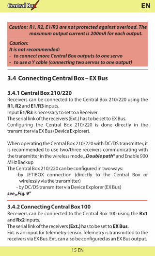
Caution:It is not recommended:- to connect more Central Box outputs to one servo- to use a Y cable (connecting two servos to one output)
Caution: R1, R2, E1/R3 are not protected against overload. The maximum output current is 200mA for each output.
3.4 Connecting Central Box – EX Bus
3.4.1 Central Box 210/220Receivers can be connected to the Central Box 210/220 using the R1, R2 and E1/R3 inputs.Input E1/R3 is necessary to set to a Receiver.The serial link of the receivers (Ext.) has to be set to EX Bus.Configuring the Central Box 210/220 is done directly in the transmitter via EX Bus (Device Explorer).
When operating the Central Box 210/220 with DC/DS transmitter, it is recommended to use two/three receivers communicating with the transmitter in the wireless mode „Double path" and Enable 900 MHz BackupThe Central Box 210/220 can be configured in two ways: -by JETIBOX connection (directly to the Central Box or
wirelessly via the transmitter) - by DC/DS transmitter via Device Explorer (EX Bus)see „Fig. 9"
3.4.2 Connecting Central Box 100Receivers can be connected to the Central Box 100 using the Rx1 and Rx2 inputs.The serial link of the receivers (Ext.) has to be set to EX Bus.Ext. is an input for telemetry sensor. Telemetry is transmitted to the receivers via EX Bus. Ext. can also be configured as an EX Bus output.
15 EN

EN
Configuring the Central Box 100 is done directly in thetransmitter via EX Bus (Device Explorer).The outputs that have been configured as EX Bus outputs can be used for connecting devices supporting this standard, such as Central Boxes and certain kinds of sensors.When operating the Central Box 100 with DC/DS transmitter, it is recommended to use two receivers communicating with the transmitter in the wireless mode „Double path".The Central Box 100 can be configured in two ways: - by JETIBOX connection (directly to the Central Box or wirelessly
via the transmitter) - by DC/DS transmitter via Device Explorer (EX Bus)see „Fig.10"
Fig. 9: Block diagram of Central Box 210/220 connection - EX Bus variant
E1/E2
R1R2
E3
R3
22022022015 channel protected servo interface
InputVoltage
Rsat2 (R2)
Rsat2 (R1)
Ext.
Ext.
SERV
O
SERVO
SERVO/SensorJetibox/Sensor
RC SwitchMagnetic Switch
16 EN
EN
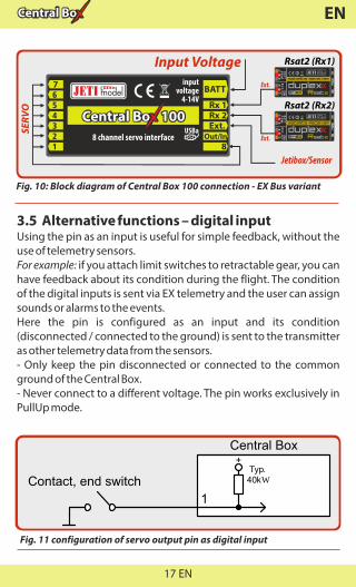
3.5 Alternative functions – digital inputUsing the pin as an input is useful for simple feedback, without the use of telemetry sensors. For example: if you attach limit switches to retractable gear, you can have feedback about its condition during the flight. The condition of the digital inputs is sent via EX telemetry and the user can assign sounds or alarms to the events.Here the pin is configured as an input and its condition (disconnected / connected to the ground) is sent to the transmitter as other telemetry data from the sensors.- Only keep the pin disconnected or connected to the common ground of the Central Box.- Never connect to a different voltage. The pin works exclusively in PullUp mode.
7
Rx 1Rx 2Ext.
Out/In
BATT
88 channel servo interface
100100100
inputvoltage
4-14V
Input Voltage
SERV
O
Rsat2 (Rx1)
Rsat2 (Rx2)
Jetibox/Sensor
Fig. 10: Block diagram of Central Box 100 connection - EX Bus variant
Ext.
Ext.
1
Contact, end switch
+
Central Box
Typ. 40kW
Fig. 11 configuration of servo output pin as digital input
17 EN
EN
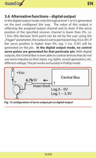
3.6 Alternative functions – digital outputIn the digital output mode, only the logical level 1 or 0 is generated on the port configured this way. The value of this output is reflecting the assigned output channel and its level. If the servo position of the specified receiver channel is lower than 0%, i.e. 1.5ms (the decision limit point can be set by the user using the „Trigger" parameter), the output is set to permanent log. 0 (i.e. 0V). If the servo position is higher than 0%, log. 1 (i.e. 3.3V) will be generated on the pin. In the digital output mode, no control servo pulses are generated for that particular pin. With digital outputs, the Central Box is even able to control devices that do not use servo impulse as their input, e.g. lights, sound generators, etc. different voltage. The pin works exclusively in PullUp mode.
Fig. 12 configuration of servo output pin as digital output
Central Box
1
+Vcc
Log.1 – 3.3VLog.0 - 0V
Imax=5mA
4.7kW
18 EN
EN
8
Rx1Rx2Ext.
+ -S
Imax=100mA OUTPUT
OUT/IN
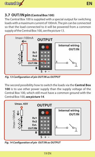
3.7 OUT/IN pin (Central Box 100)The Central Box 100 is supplied with a special output for switching loads with a maximum current of 100mA. The pin can be connected so that the load connected to it will be powered from a common supply of the Central Box 100, see the picture 13.
S
Internal wiringOUT/IN
Fig. 13 Configuration of pin OUT/IN as OUTPUT
The second possibility how to switch the loads via the Central Box 100 is to use other power supply than the supply voltage of the Central Box 100, which still must have a common ground with the Central Box 100, see picture 14.
8
Rx1Rx2Ext.
+ -S
Imax
=100
mA
OUTPUT
OUT/IN
Fig. 14 Configuration of pin OUT/IN as OUTPUT
Umax. 45V
S
Internal wiringOUT/IN
19 EN

EN
Picture 15 depicts OUT/IN pin in the input function.
8
Rx1Rx2Ext.
+ -S
INPUT
OUT/IN
+
S
Internal wiringOUT/IN
Typ.40kW
Fig. 15 Configuration of pin OUT/IN as INPUT
20 EN
EN
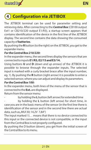
4 Configuration via JETIBOXThe JETIBOX terminal can be used for parameter setting and retrieving data. After connecting to the Central Box (CB100 output Ext1 or CB210/220 output E1/R3), a startup screen appears that contains identification of the device in the first line of the JETIBOX display. The second line contains the data showing the consumed capacity of batteries.By pushing the R button (to the right) on the JETIBOX, you get to the expander menu.For the Central Box 210/220:In the expander menu, the second lines display the sensors that are connected to inputs E1/R3, E2/15 and E3/14.Using buttons U and D (down and up arrows) of the JETIBOX it is possible to browse through the expander inputs. The selected input is marked with a curly bracket brace after the input number, eg. 1}. By pushing the R button (right arrow) it is possible to enter a selected sensor, where you can adjust and display its parameters.For the Central Box 100:In the expander menu, both lines of the menu of the sensor that is connected to the Ext. are displayed.Return from the sensor menu:- by holding the L button (left arrow) for extended time- by holding the L button (left arrow) for short time, in case you are in the basic menu of the sensor (in the first line there is identification of the sensor and in the second line there are actual data, such as „MUI 30; 14,2V 7,8A“)The input marked 1}… means that there is no device connected to this input or the connected device is not compatible, or the input from the Central Box is not properly configured.By pushing the D button (down), you get from the initial screen of the Central Box to its menu.
21 EN

EN
• Temperature - actual temperature of Central Box• Information on the status of receivers - number of detected channels and the period of signal
4.2 Minimum / Maximum values*CENTRAL BOX*: MIN / MAX – by pushing the D button (down arrow) you select a display of extreme voltage, current, temperature, and status of the receiver, which occurred during the operation. • Erase data – (CB210 and CB220) by pushing the arrows R and L (right and left) together, the minimum and maximum are reset, see "MIN / MAX - Minimum / Maximum".• Minimal voltage – the lowest voltage detected by the Central Box on the inputs during its operations• Maximal voltage – the highest voltage detected by the Central Box on the inputs during its operation
4.1 Actual values*CENTRAL BOX*: Actual Value – by pushing the D button (down arrow) you select the display of actual measured values • Accu voltage - shows the actual voltage of both inputs • Accu current - displays the actual current flowing from the battery to the output• Accu capacity - consumed capacity of each battery• Over-I Monitor (CB100/220) - indication of servo output; (-) output is fine (x) the output is overloaded. Outputs are ordered:
Fig. 16: Description of outputs
22 EN

EN
• Maximal current – the highest current detected by the Central Box on the inputs during its operation• Min/Max Temper. - the highest and the lowest temperature of the Central Box during its operation (since the last manual reset)
Statistics of the received signal expressed in timeR1: how long was the signal from the primary receiver available to the Central BoxR2: how long was the signal from the secondary receiver available to the Central Box R3: how long was the signal from the third receiver availableto the Central Box 210/220Statistics of the received signal expressed as a percentageR1: what percentage of the total operating time was the signal from the primary receiver available to the Central BoxR2: what percentage of the total operating time was the signal from the secondary receiver available to the Central BoxR3: what percentage of the total operating time was the signal fromthe third receiver available to the Central Box 210/220
• Over-I Monitor (CB100/220) - indication of servo output during the operating time of the Central Box; (-) output is fine (x) the output is overloaded
4.3 Setting*CENTRAL BOX*: SETTING – By pushing the D button (down arrow) you get to the basic setting of the device.• Fail Safe – switches on/off of the Fail Safe function. If the Fail Safe function is deactivated, there is no signal generated in any Central Box outputs at the signal loss. If you activate the Fail Safe function, you can also select how the Central Box responds at the signal loss for each of the individual outputs (OUT off, hold, fail safe).• Signal Fault Delay – the length of time from when the Central Box detects a signal loss to when the programmed Fail Safe output
23 EN

EN
is performed. During this time the last servo input is held. After the selected time has elapsed, the Central Box outputs behave according to setting for each specific output.• Output Period – setting for the period of the output signals (default Auto-synchronous mode with the transmitter). This parameter significantly affects the behavior of the servos. For analog servos the reaction (response) accelerates and the power consumption is higher when the values for the output period are lower. This can lead to vibration in some servos if the values are set too low.• Erase data –(Cb100) by pushing the arrows R and L (right and left) together, the minimum and maximum are reset, see "MIN / MAX - Minimum / Maximum".• Rx Switchover (CB 210/220) - Timeout (150ms) – If the connection from the receiver is lost for
more than 150ms the Central Box switches to another active receiver. This strategy was used in the previous versions of the firmware.
- Timeout (80ms) – If the connection from the receiver is lost for more than 80ms the Central Box switches to another active receiver.
- Mixing – The Central Box combines data from all active receiver inputs and uses it for servos on the packet-by-packet basis. This strategy is available only if receivers are connected to the Central Box via EX Bus. Another type of serial communication is not supported. Mixing strategy is not suitable for a combination of Assist receiver with standard receiver(s). It could lead to inconsistent servo data if signal from the Assist receiver is mixed with signal from the standard receiver.
Please note that the switch over strategy for ports configured as EX Bus output is kept the same as in the Timeout (150ms) mode.
24 EN

EN
4.4 Out Pin Set*CENTRAL BOX*: Out Pin Set – pushing the D button (down arrow) moves you to basic settings of particular outputs of the Central Box.• Set Output pin -selection of the slot that will be used for the following settings. In this menu the output deflection of the selected output is displayed as a percentage. Y1 is the Central Box output labeled 1, Y2 is the Central Box labeled 2, etc.• Function – setup of alternative output functions. This function is available only for these outputs:Central Box 210/220: • Y1 to Y13: Functions - Servo output, digital input, digital
output and Ditex • Y14 and Y15: Functions - Servo output, Servo output, digital
input, digital output, telemetry input, EX Bus, Ditex, S.BUS output (only for Y15), telemetry input, and EX Bus
• E1/R3: Functions - Telemetry input, JETIBOX, EX Bus and receiver
Central Box 100: • Y1 to Y8: Functions - Servo output, digital input, digital
output • OUT/IN: Digital input and digital output • EXT1: Functions - Telemetry input, JETIBOX and EX Bus• SetInChannel – assigns the input channel (marked as Chx) to a specific output (marked as Yx)• Reverse – reverses the output direction• Signal Fault - setting behavior of the receiver in case of signal loss • hold - repeats the last valid deflection command before
signal loss • out off – does not generate any signal for servo in case of
signal loss • FailSafe – transition to preset deflection of individual outputs• FS position – setup of the selected output deflection in case of signal loss
25 EN

EN
• FS speed – setup for how quickly the output transitions to its programmed deflection in case of signal loss• ATV High Limit Yx – sets the upper travel (throw) limit of the output • ATV Low Limit Yx – sets the lower travel (throw) limit of the output • Output Trim – setting the neutral deflection of the receiver output• Output Group – setting the output to a selected group of output pulses that will be generated from the receiver at the same time
For the function of digital output it is possible to assign the Y input – adjusting an input channel (labeled as Chx) to a specific output (labeled as Yx)TriggerLevel Y – the decision level for digital output. If the servo position of the specified channel is lower than „TriggerLevelY", the output is set to log. 0. Otherwise the output is set to logical 1.OppositeDirection Y- reversing output directionFailSafe.Y- setup of the Central Box behavior in case of the signal lossrepeat – repeating the last valid figure on the outputlog.1 – logical 1 is generated on the outputlog.0 – logical 0 is generated on the output
4.5 Alarms*CENTRAL BOX*: Alarms – pushing the D button (down arrow) moves you to the menu for setting the alarms. If the alarm is set to OFF, the alarm is deactivated.• Capacity Alarm - level of the capacity taken from the battery at which the alarm will sound • Current Alarm - level of current drawn from the battery at whichthe alarm will sound • Voltage Alarm – if the battery voltage drops below this level, thealarm will sound
26 EN

EN
• S h o r t C i r c u i t A l a r m ( C B 1 0 0 a n d C B 2 2 0 ) - Activating/deactivating the alarm for when the outputs are overloaded • Temperature Alarm – Activating/deactivating alarms for the Central Box overheating Temperature goes above 70/90°C for Central Box 220/210. • Alarm Rx – the alarm is generated if the Central Box does notreceive any information about valid servo positions from the R1input for a period longer than 1s
4.6 Service information*CENTRAL BOX*: SERVICE – pushing the D button (down arrow) moves you to the display of the firmware version and the menu for restoring the default settings of the Central Box.• Language Setup - (Central Box 210/220) Language of the menu in Jetibox• PresetToSetup – pushing arrows R and L (right and left) together leads to loading the default settings of the Central Box• CBOXxxx v. xx.xx ID xxxxx:xxxxx – designation of the product with the firmware version and the serial number (ID)
27 EN
EN
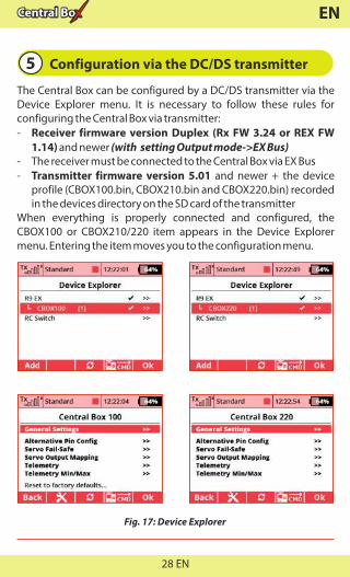
5 Configuration via the DC/DS transmitter
The Central Box can be configured by a DC/DS transmitter via the Device Explorer menu. It is necessary to follow these rules for configuring the Central Box via transmitter:- Receiver firmware version Duplex (Rx FW 3.24 or REX FW 1.14) and newer (with setting Output mode->EX Bus)- The receiver must be connected to the Central Box via EX Bus- Transmitter firmware version 5.01 and newer + the device profile (CBOX100.bin, CBOX210.bin and CBOX220.bin) recorded in the devices directory on the SD card of the transmitterWhen everything is properly connected and configured, the CBOX100 or CBOX210/220 item appears in the Device Explorer menu. Entering the item moves you to the configuration menu.
Fig. 17: Device Explorer
28 EN
EN
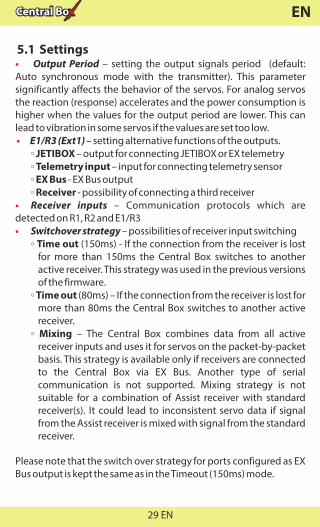
5.1 Settings• Output Period – setting the output signals period (default: Auto synchronous mode with the transmitter). This parameter significantly affects the behavior of the servos. For analog servos the reaction (response) accelerates and the power consumption is higher when the values for the output period are lower. This can lead to vibration in some servos if the values are set too low. • E1/R3 (Ext1) – setting alternative functions of the outputs. ◦ JETIBOX – output for connecting JETIBOX or EX telemetry ◦ Telemetry input – input for connecting telemetry sensor ◦ EX Bus - EX Bus output Receiver - possibility of connecting a third receiver◦• Receiver inputs – Communication protocols which are detected on R1, R2 and E1/R3• Switchover strategy – possibilities of receiver input switching ◦ Time out (150ms) - If the connection from the receiver is lost
for more than 150ms the Central Box switches to another active receiver. This strategy was used in the previous versions of the firmware.
◦ Time out (80ms) – If the connection from the receiver is lost for more than 80ms the Central Box switches to another active receiver.
◦ Mixing – The Central Box combines data from all active receiver inputs and uses it for servos on the packet-by-packet basis. This strategy is available only if receivers are connected to the Central Box via EX Bus. Another type of serial communication is not supported. Mixing strategy is not suitable for a combination of Assist receiver with standard receiver(s). It could lead to inconsistent servo data if signal from the Assist receiver is mixed with signal from the standard receiver.
Please note that the switch over strategy for ports configured as EX Bus output is kept the same as in the Timeout (150ms) mode.
29 EN

EN
Fig. 18: Device Explorer-General Settings
5.2 Alternate functions of pins
Overall setting of alternate functions for individual pins of the Central Box. Possible settings:
- Servo out.- servo control signal will be generated for the pin - Digi. output –log. 1 or log. 0 is generated on the output according
to the position of the assigned channel and according to the trigger level. If the servo position of the assigned channel is lower than „Trigger", the output is set to log. 0. Otherwise the output is set to logical 1.
- Digi. input – the condition of the pin is sent to the transmitter via EX telemetry.
- Telemetry input - input for connecting telemetry sensor with automatic detection of the connected EX Bus sensor
- EX Bus – data output sending channel positions, telemetry, and device configuration
- Ditex (CB210 and CB220 only) – support of telemetry DITEX servos
30 EN

EN
Fig. 19
5.3 Servo Fail-Safe
In all connected receivers we recommend disable Fail-Safe and set it in the Central Box only.• Fail Safe – switches on/off the Fail-Safe function. If the Fail-Safefunction is deactivated, there is no signal generated in any CentralBox outputs at signal loss. If you activate the Fail-Safe function, thebehavior of the Central Box output corresponds with the setting ofindividual outputs (Out off, Hold, Fail-Safe).• Fail-Safe Delay – the period of time during which the last validservo positions are repeated if the signal loss is detected. After theselected time has elapsed, the Central Box outputs behaveaccording to setting for each specific output.• Fail-Safe setup now … - sets the current position for the Fail-Safe value• Mode - Fail-Safe mode for a specific Central Box output ◦ Hold: repeats the last known servo position before the signal
loss ◦ Out OFF: does not generate any signal for servos in case of the
signal loss ◦ Fail-Safe: generates pre-set servo position (value) if signal loss
is detected. Can be programmed with slowdown (Speed)
31 EN

EN
Fig. 20: Device Explorer-Fail Safe
The Fail-Safe position can be immediately applied to the CentralBox output if the cursor is on the „Value" menu item and you pushthe F4 function key. „F4 (Apply)".
5.4 Servo Output Mapping
• Servo No. – assigning outputs of the transmitter to the Central Box outputs (Output pin).• Group – assigns specific output to the group of output impulses that will be generated from the receiver in the same time
Fig. 21: Device Explorer-Servo Output Mapping
32 EN

EN
5.5 Telemetry• Temp. – actual temperature of the Central Box• Shorted outputs No.(CB100 and CB220 only) – actual number of overloaded outputs• Voltage – actual voltage of individual outputs of the Central Box• Current – actual current drawn from the battery • Capacity – capacity taken from the batteries
Fig. 22: Device Explorer-Telemetry
5.6 Telemetry Min/Max
• Clear Min/Max switch – here you can assign a control (switch, stick or knob) on the DC/DS transmitter which clears the recorded battery capacity and minimum/maximum values in the Central Box.• Clear Now – allows you to immediately clear the recorded battery capacity and minimum/maximum values in the Central Box.
33 EN

EN
Fig. 23: Device Explorer-Telemetry Min/Max
5.7 Reset to factory settings
• Reset to factory settings – reset to factory setting of the Central Box (you can find it in the general settings)
For description of individual items, see the chapter Minimum/Maximum values.
34 EN

EN
6 Firmware update
E1/E2
R1R2
E3
R3
22022022015 channel protected servo interface
Power supply
USBa
USB adapter
PC
Central Box allows firmware update via a PC. The update is performed using the JETI USBa (USB adapter). The procedure is as shown below: On the manufacturer internet pages (www.jetimodel.com), under „Downloads", you will find an Jeti Studio program with the most recent firmware. Download it to your PC and install.1. Start the Jeti Studio update program on your PC and select the
correct COM port.2. Connect the Central Box output labeled Ext1 or E1/R3 with the
USB adapter by means of interconnection cable.3. Connect the Central Box to the power supply. Switch on the
Central Box using the magnetic switch or the RC switch.4. Jeti Studio automatically detects the connected device and
offers you the latest update.5. Select FW and click the "Update" button. The update starts and
runs automatically.
RC SwitchMagnetic Switch
35 EN

EN
7
Rx 1Rx 2Ext.
Out/In
BATT
88 channel servo interface
100100100
inputvoltage
4-14V
Power supply
USBa
USB adapter
PC
7 Safety precautions for working with magnets
Because the Central Box is put into operation via magnet, it is necessary to follow safety precautions for handling magnets. The magnet is mounted in a hard aluminum carrier.
1. Keep the magnetic key a safe distance from all devices that could be damaged by the magnet, such as TV, credit cards, computers, etc. The magnet may interfere with the function of pacemakers!
2. Keep magnets away from children because of the danger of swallowing or pinching!
36 EN
EN
8 Technical specifications of the Central Box
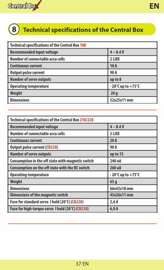
Technical specifications of the Central Box 210/220Recommended input voltage 4 – 8.4 VNumber of connectable accu cells 2 LiXX Continuous current 20 AOutput pulse current ( )CB220 90 A Number of servo outputs up to 15Consumption in the off state with magnetic switch 240 uA Consumption on the off state with the RC switch 260 uAOperating temperature - 20°C up to +75°CWeight 65 gDimensions 66x42x18 mmDimensions of the magnetic switch 45x26x11 mmFuse for standard servo I hold (20°C) ( )CB220 2,6 AFuse for high-torque servo I hold (20°C) ( )CB220 6,0 A
Technical specifications of the Central Box 100Recommended input voltage 4 – 8.4 VNumber of connectable accu cells 2 LiXXContinuous current 10 AOutput pulse current 90 A Number of servo outputs up to 8Operating temperature - 20°C up to +75°CWeight 20 gDimensions 52x25x11 mm
37 EN

EN
9 Warranty, service and the technical support
Warranty and serviceThis product is covered by warranty for 24 months after the day of purchase provided that it has been operated in accordance with these instructions at the specified voltage and is not mechanically damaged. When claiming warranty repairs for the product, always attach a proof of purchase. Warranty and post-warranty service is provided by your dealer or the manufacturer.
Technical supportIn case you are not sure about the setup or some functions of the product, do not hesitate to contact our technical support. You can contact either your dealer, or directly the manufacturer JETI model s.r.o.. For further information see our webpages www.jetimodel.com.
We wish you sucessful flying with the products of: JETI model s.r.o. Příbor, www.jetimodel.com
38 EN
EN
Tomáš Klesnilproduction Manager
®
Declaration of Conformity
Issues name & addres:JETI model s.r.o.Lomena 1530, 742 58 Pribor
Object of the declaration:
Products: Servo interfaceTrade name: Central Box
Model: Central Box 100, 210, 220Country of origin: Czech republic
The object of declaration described above is in conformity with the requirements of the folowing EU legislations and harmonized standards:ČSN EN 61000-6-1:2007, ČSN EN 61000-6-3:2007+A1:20011Electromagnetic compatibility: 6440-454/2008 6440-538/2008
Signed for and on behalf of:
39 EN

EN
40 EN


![MultidimensionalRankReductionEstimator forParametricMIMOChannelModels · 2017. 8. 28. · conventional ESPRIT algorithm [7] and the multidimen-sional ESPRIT (MD ESPRIT) algorithm](https://static.fdocuments.in/doc/165x107/60d81e8baa8017424c077cbf/multidimensionalrankreductionestimator-forparametricmimochannelmodels-2017-8-28.jpg)