EN Plural Component, Impingement Mix Air Purge … EN Instructions - Parts Plural Component,...
48
309550ZAL EN Instructions - Parts Plural Component, Impingement Mix Air Purge Spray Gun For use with non-flammable foam and polyurea. For professional use only. Not for use in explosive atmospheres. 3500 psi (24.5 MPa, 245 bar) Maximum Fluid Working Pressure 80-130 psi (0.56-0.9 MPa, 5.6-9.0 bar) Air Inlet Pressure Range 200°F (94°C) Maximum Fluid Temperature Important Safety Instructions Read all warnings and instructions in this manual. Save these instructions. TI2408-1A
Transcript of EN Plural Component, Impingement Mix Air Purge … EN Instructions - Parts Plural Component,...

309550ZALEN
Instructions - Parts
Plural Component, Impingement MixAir Purge Spray GunFor use with non-flammable foam and polyurea. For professional use only.
Not for use in explosive atmospheres.
3500 psi (24.5 MPa, 245 bar) Maximum Fluid Working Pressure80-130 psi (0.56-0.9 MPa, 5.6-9.0 bar) Air Inlet Pressure Range200°F (94°C) Maximum Fluid Temperature
Important Safety InstructionsRead all warnings and instructions in this manual.Save these instructions.
TI2408-1A

Manual Conventions
2 309550
ContentsManual Conventions . . . . . . . . . . . . . . . . . . . . . . . . 2List of Models/Mix Chamber Selection Guide . . . . 3
Round Pattern Guns . . . . . . . . . . . . . . . . . . . . . . 3Flat Pattern Guns . . . . . . . . . . . . . . . . . . . . . . . . 4Flat Pattern Guns, continued . . . . . . . . . . . . . . . 5Flat Pattern Stud Wall Gun . . . . . . . . . . . . . . . . . 5Spatter Pattern Gun . . . . . . . . . . . . . . . . . . . . . . 6Wide Round Pattern Gun . . . . . . . . . . . . . . . . . . 6Four-Hose Gun . . . . . . . . . . . . . . . . . . . . . . . . . . 6Non 1:1 Ratio Guns . . . . . . . . . . . . . . . . . . . . . . 6
Overall View . . . . . . . . . . . . . . . . . . . . . . . . . . . . . . . 9Important Isocyanate (ISO) Information . . . . . . . 10
Material Self-ignition . . . . . . . . . . . . . . . . . . . . . 11Keep Components A and B Separate . . . . . . . . 11Moisture Sensitivity of Isocyanates . . . . . . . . . . 11Foam Resins with 245 fa Blowing Agents . . . . . 12Changing Materials . . . . . . . . . . . . . . . . . . . . . . 12
Grounding . . . . . . . . . . . . . . . . . . . . . . . . . . . . . . . 12Piston Safety Lock . . . . . . . . . . . . . . . . . . . . . . . . 12Turning Air Cap . . . . . . . . . . . . . . . . . . . . . . . . . . . 13Loss of Air Pressure . . . . . . . . . . . . . . . . . . . . . . . 13Setup . . . . . . . . . . . . . . . . . . . . . . . . . . . . . . . . . . . . 14Shutdown . . . . . . . . . . . . . . . . . . . . . . . . . . . . . . . . 16Pressure Relief Procedure . . . . . . . . . . . . . . . . . . 17Optional Configurations . . . . . . . . . . . . . . . . . . . . 18
Optional Fluid Manifold Position . . . . . . . . . . . . 18Optional Hose Position . . . . . . . . . . . . . . . . . . . 18
Flat Spray Tips . . . . . . . . . . . . . . . . . . . . . . . . . . . . 19Maintenance . . . . . . . . . . . . . . . . . . . . . . . . . . . . . . 20
Supplied Tool Kit . . . . . . . . . . . . . . . . . . . . . . . . 20Keep Gun Clean . . . . . . . . . . . . . . . . . . . . . . . . 20As Needed . . . . . . . . . . . . . . . . . . . . . . . . . . . . 20Daily . . . . . . . . . . . . . . . . . . . . . . . . . . . . . . . . . 20Weekly to Monthly . . . . . . . . . . . . . . . . . . . . . . . 20
Flush Gun . . . . . . . . . . . . . . . . . . . . . . . . . . . . . 21Clean Outside of Gun . . . . . . . . . . . . . . . . . . . . 21Clean Air Cap . . . . . . . . . . . . . . . . . . . . . . . . . . 21Clean Muffler . . . . . . . . . . . . . . . . . . . . . . . . . . . 21Clean Fluid Manifold . . . . . . . . . . . . . . . . . . . . . 21Clean Mix Chamber Nozzle . . . . . . . . . . . . . . . . 22Clean Passages . . . . . . . . . . . . . . . . . . . . . . . . . 22Clean Impingement Ports . . . . . . . . . . . . . . . . . 22
Troubleshooting . . . . . . . . . . . . . . . . . . . . . . . . . . . 24Theory of Operation . . . . . . . . . . . . . . . . . . . . . . 26Cutaway View . . . . . . . . . . . . . . . . . . . . . . . . . . 27
Repair . . . . . . . . . . . . . . . . . . . . . . . . . . . . . . . . . . . 28Tools Required . . . . . . . . . . . . . . . . . . . . . . . . . . 28Lubrication . . . . . . . . . . . . . . . . . . . . . . . . . . . . . 28Remove Front End . . . . . . . . . . . . . . . . . . . . . . . 28Attach Front End . . . . . . . . . . . . . . . . . . . . . . . . 29Mix Chamber and Side Seal Cartridges . . . . . . 30Check Valves . . . . . . . . . . . . . . . . . . . . . . . . . . . 32Piston . . . . . . . . . . . . . . . . . . . . . . . . . . . . . . . . . 33Piston Safety Lock . . . . . . . . . . . . . . . . . . . . . . . 34Air Valve . . . . . . . . . . . . . . . . . . . . . . . . . . . . . . . 34
Notes . . . . . . . . . . . . . . . . . . . . . . . . . . . . . . . . . . . . 35Parts . . . . . . . . . . . . . . . . . . . . . . . . . . . . . . . . . . . . 36
Mix Chamber Kits . . . . . . . . . . . . . . . . . . . . . . . 39Flat Tip Kits . . . . . . . . . . . . . . . . . . . . . . . . . . . . 40Gun Repair Kits . . . . . . . . . . . . . . . . . . . . . . . . . 40Check Valve Filter Screen Kits . . . . . . . . . . . . . . 40Drill Bit Kits . . . . . . . . . . . . . . . . . . . . . . . . . . . . 41Drill Bit Kit . . . . . . . . . . . . . . . . . . . . . . . . . . . . . 42Air Purge Handle Cleanout Drill Kit . . . . . . . . . . 42
Accessories . . . . . . . . . . . . . . . . . . . . . . . . . . . . . . 43Technical Data . . . . . . . . . . . . . . . . . . . . . . . . . . . . 47Graco Standard Warranty . . . . . . . . . . . . . . . . . . . 48Graco Information . . . . . . . . . . . . . . . . . . . . . . . . . 48
Manual ConventionsWarning Caution
Note
WARNING
A warning alerts you to possible serious injury ordeath if you do not follow instructions.
Symbols, such as fluid injection (shown), alert you to aspecific hazard and direct you to read the indicatedhazard warnings on pages 7-8.
CAUTION
A caution alerts you to possible equipment damage ordestruction if you do not follow instructions.
A note indicates additional helpful information.
List of Models/Mix Chamber Selection Guide
309550 3
List of Models/Mix Chamber Selection Guide
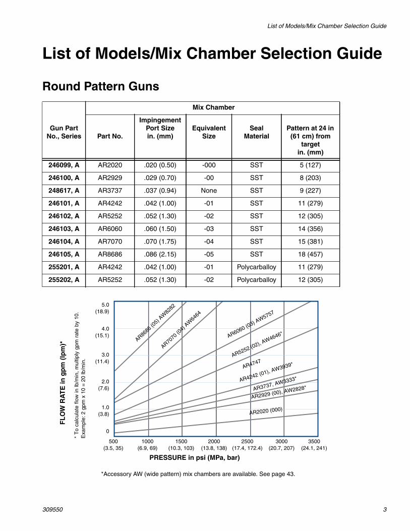
Round Pattern Guns
Mix Chamber
Gun PartNo., Series Part No.
ImpingementPort Sizein. (mm)
EquivalentSize
SealMaterial
Pattern at 24 in(61 cm) from
targetin. (mm)
246099, A AR2020 .020 (0.50) -000 SST 5 (127)
246100, A AR2929 .029 (0.70) -00 SST 8 (203)
248617, A AR3737 .037 (0.94) None SST 9 (227)
246101, A AR4242 .042 (1.00) -01 SST 11 (279)
246102, A AR5252 .052 (1.30) -02 SST 12 (305)
246103, A AR6060 .060 (1.50) -03 SST 14 (356)
246104, A AR7070 .070 (1.75) -04 SST 15 (381)
246105, A AR8686 .086 (2.15) -05 SST 18 (457)
255201, A AR4242 .042 (1.00) -01 Polycarballoy 11 (279)
255202, A AR5252 .052 (1.30) -02 Polycarballoy 12 (305)
FL
OW
RA
TE
ing
pm
(lp
m)*
PRESSURE in psi (MPa, bar)
5.0(18.9)
4.0(15.1)
3.0(11.4)
1.0(3.8)
2.0(7.6)
0
AR4242 (01), AW3939*
AR2929 (00), AW2828*
AR2020 (000)
500(3.5, 35)
1000(6.9, 69)
1500(10.3, 103)
2000(13.8, 138)
2500(17.4, 172.4)
3000(20.7, 207)
3500(24.1, 241)
*T
oca
lcul
ate
flow
inlb
/min
,m
ultip
lygp
mra
teby
10.
Exa
mpl
e:2
gpm
x10
=20
lb/m
in.
AR6060 (03) AW5757
AR5252 (02), AW4646*
AR7070
(04)
AW64
64
AR8686
(05)
AW82
82
AR3737, AW3333*
*Accessory AW (wide pattern) mix chambers are available. See page 43.
AR4747

List of Models/Mix Chamber Selection Guide
4 309550
Flat Pattern Guns
Mix Chamber Flat Tip
Gun PartNo., Series Part No.
ImpingementPort Sizein. (mm)
EquivalentSize Part No.
Pattern Sizein. (mm)
Orifice Sizein. (mm)
247101, A AF2020 .020 (0.50) -000 FT0424 8-10 (203-254) .024 (0.61)
247102, A AF2020 .020 (0.50) -000 FT0438 8-10 (203-254) .038 (0.97)
247103, A AF2020 .020 (0.50) -000 FT0624 12-14 (305-356) .024 (0.61)
247104, A AF2020 .020 (0.50) -000 FT0638 12-14 (305-356) .038 (0.97)
247107, A AF2020 .020 (0.50) -000 FT0838 16-18 (406-457) .038 (0.97)
247108, A AF2020 .020 (0.50) -000 FT0848 16-18 (406-457) .048 (1.22)
247111, A AF2929 .029 (0.70) -00 FT0424 8-10 (203-254) .024 (0.61)
247112, A AF2929 .029 (0.70) -00 FT0438 8-10 (203-254) .038 (0.97)
247113, A AF2929 .029 (0.70) -00 FT0624 12-14 (305-356) .024 (0.61)
247114, A AF2929 .029 (0.70) -00 FT0638 12-14 (305-356) .038 (0.97)
247117, A AF2929 .029 (0.70) -00 FT0838 16-18 (406-457) .038 (0.97)
247118, A AF2929 .029 (0.70) -00 FT0848 16-18 (406-457) .048 (1.22)
247121, A AF4242 .042 (1.00) -01 FT0424 8-10 (203-254) .024 (0.61)
247122, A AF4242 .042 (1.00) -01 FT0438 8-10 (203-254) .038 (0.97)
247123, A AF4242 .042 (1.00) -01 FT0624 12-14 (305-356) .024 (0.61)
247124, A AF4242 .042 (1.00) -01 FT0638 12-14 (305-356) .038 (0.97)
247127, A AF4242 .042 (1.00) -01 FT0838 16-18 (406-457) .038 (0.97)
247128, A AF4242 .042 (1.00) -01 FT0848 16-18 (406-457) .048 (1.22)
247131, A AF5252 .052 (1.30) -02 FT0424 8-10 (203-254) .024 (0.61)
247132, A AF5252 .052 (1.30) -02 FT0438 8-10 (203-254) .038 (0.97)
247133, A AF5252 .052 (1.30) -02 FT0624 12-14 (305-356) .024 (0.61)
247134, A AF5252 .052 (1.30) -02 FT0638 12-14 (305-356) .038 (0.97)
247137, A AF5252 .052 (1.30) -02 FT0838 16-18 (406-457) .038 (0.97)
247138, A AF5252 .052 (1.30) -02 FT0848 16-18 (406-457) .048 (1.22)

List of Models/Mix Chamber Selection Guide
309550 5
Flat Pattern Guns, continued
Flat Pattern Stud Wall GunSee manual number 311071 for more information.
FL
OW
RA
TE
ing
pm
(lp
m)*
PRESSURE in psi (MPa, bar)
2.25(8.55)
3.0(11.4)
0.75(2.85)
1.5(5.7)
0
AF4242 with FTXX38 tip
AF2929 with FTXX38 tip
AF2020 with FTXX24 tip
500(3.5, 35)
1000(6.9, 69)
1500(10.3, 103)
2000(13.8, 138)
2500(17.4, 172.4)
3000(20.7, 207)
3500(24.1, 241)
*T
oca
lcul
ate
flow
inlb
/min
,m
ultip
lygp
mra
teby
10.
Exa
mpl
e:2
gpm
x10
=20
lb/m
in.
AF5252 with FTXX48 tip
Mix Chamber Flat Tip Flow Data
Gun PartNo., Series Part No.
ImpingementPort Sizein. (mm)
Equiva-lent Size Part No.
Pattern Dia. at24 in. (610 mm)
to Targetin. (mm)
Orifice Sizein. (mm)
ApproximateFlow Rate at
1000 psi(7.0 MPa, 70 bar)
249525 AF4242 .042 (1.00) -01 FTM979 22 (559) .038 (0.97) 11 lb/min(4.99 kg/min)
249526 AF5252 .052 (1.30) -02 FTM979 22 (559) .038 (0.97) 15 lb/min(6.81 kg.min)
List of Models/Mix Chamber Selection Guide
6 309550
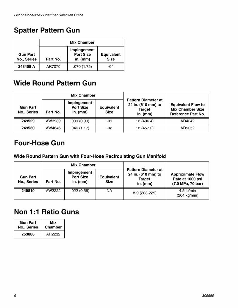
Spatter Pattern Gun
Wide Round Pattern Gun
Four-Hose Gun
Wide Round Pattern Gun with Four-Hose Recirculating Gun Manifold
Non 1:1 Ratio Guns
Mix Chamber
Gun PartNo., Series Part No.
ImpingementPort Sizein. (mm)
EquivalentSize
248408 A AR7070 .070 (1.75) -04
Mix ChamberPattern Diameter at24 in. (610 mm) to
Targetin. (mm)
Equivalent Flow toMix Chamber SizeReference Part No.
Gun PartNo., Series Part No.
ImpingementPort Sizein. (mm)
EquivalentSize
249529 AW3939 .039 (0.99) -01 16 (406.4) AR4242
249530 AW4646 .046 (1.17) -02 18 (457.2) AR5252
Mix ChamberPattern Diameter at24 in. (610 mm) to
Targetin. (mm)
Approximate FlowRate at 1000 psi(7.0 MPa, 70 bar)
Gun PartNo., Series Part No.
ImpingementPort Sizein. (mm)
EquivalentSize
249810 AW2222 .022 (0.56) NA8-9 (203-229)
4.5 lb/min(204 kg/min)
Gun PartNo., Series
MixChamber
253888 AR2232

Warning
309550 7
WARNINGPERSONAL PROTECTIVE EQUIPMENT
Always wear appropriate personal protective equipment and cover all skin when spraying, servicingequipment, or when in the work area. Protective equipment helps prevent serious injury, includinglong-term exposure; inhalation of toxic fumes, mists or vapors; allergic reaction; burns; eye injury andhearing loss. This protective equipment includes but is not limited to:
• A properly fitting respirator, which may include a supplied-air respirator, chemically impermeablegloves, protective clothing and foot coverings as recommended by the fluid manufacturer and localregulatory authority.
• Protective eyewear and hearing protection.
TOXIC FLUID OR FUMES HAZARDToxic fluids or fumes can cause serious injury or death if splashed in the eyes or on skin, inhaled orswallowed.
• Read Safety Data Sheet (SDS) for handling instructions and to know the specific hazards of the flu-ids you are using, including the effects of long-term exposure.
• When spraying, servicing equipment, or when in the work area, always keep work area well venti-lated and always wear appropriate personal protective equipment. See Personal Protective Equip-ment warnings in this manual.
• Store hazardous fluid in approved containers, and dispose of it according to applicable guidelines.
SKIN INJECTION HAZARDHigh-pressure fluid from gun, hose leaks, or ruptured components will pierce skin. This may look like justa cut, but it is a serious injury that can result in amputation. Get immediate surgical treatment.
• Do not point the gun at anyone or at any part of the body.
• Do not put your hand or fingers over the gun fluid nozzle.
• Do not stop or deflect leaks with your hand, body, glove, or rag.
• Do not “blow back” fluid; this is not an air spray system.
• Follow Pressure Relief Procedure, page 17, when you stop spraying and before cleaning, check-ing, or servicing equipment.
• Use lowest possible pressure when flushing, priming, or troubleshooting.
• Engage piston safety lock when not spraying.
• Tighten all fluid connections before operating the equipment.
• Check hoses, tubes, and couplings daily. Replace worn or damaged parts immediately. High pres-sure hose cannot be recoupled; replace the entire hose.
BURN HAZARDEquipment surfaces and fluid that’s heated can become very hot during operation. To avoid severeburns, do not touch hot fluid or equipment. Wait until equipment/fluid has cooled completely.
Warning
8 309550
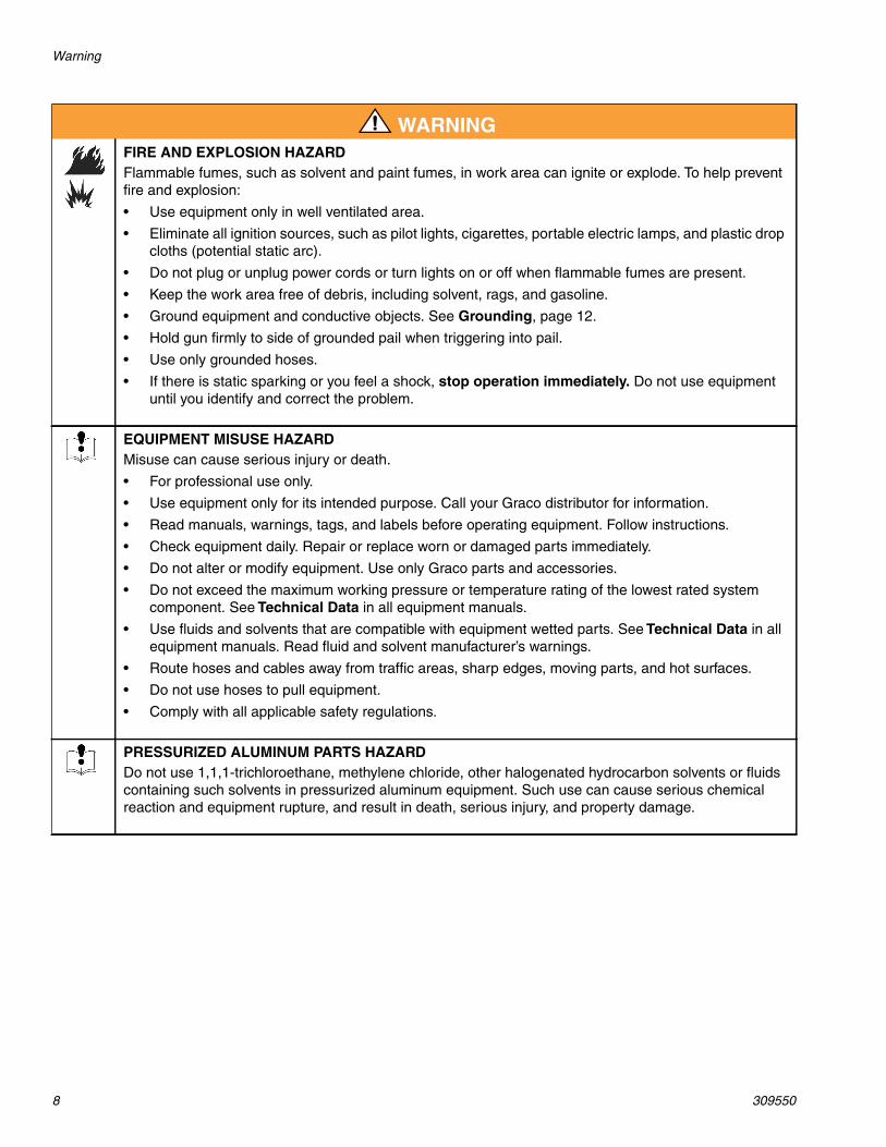
FIRE AND EXPLOSION HAZARDFlammable fumes, such as solvent and paint fumes, in work area can ignite or explode. To help preventfire and explosion:
• Use equipment only in well ventilated area.
• Eliminate all ignition sources, such as pilot lights, cigarettes, portable electric lamps, and plastic dropcloths (potential static arc).
• Do not plug or unplug power cords or turn lights on or off when flammable fumes are present.
• Keep the work area free of debris, including solvent, rags, and gasoline.
• Ground equipment and conductive objects. See Grounding, page 12.
• Hold gun firmly to side of grounded pail when triggering into pail.
• Use only grounded hoses.
• If there is static sparking or you feel a shock, stop operation immediately. Do not use equipmentuntil you identify and correct the problem.
EQUIPMENT MISUSE HAZARDMisuse can cause serious injury or death.
• For professional use only.
• Use equipment only for its intended purpose. Call your Graco distributor for information.
• Read manuals, warnings, tags, and labels before operating equipment. Follow instructions.
• Check equipment daily. Repair or replace worn or damaged parts immediately.
• Do not alter or modify equipment. Use only Graco parts and accessories.
• Do not exceed the maximum working pressure or temperature rating of the lowest rated systemcomponent. See Technical Data in all equipment manuals.
• Use fluids and solvents that are compatible with equipment wetted parts. See Technical Data in allequipment manuals. Read fluid and solvent manufacturer’s warnings.
• Route hoses and cables away from traffic areas, sharp edges, moving parts, and hot surfaces.
• Do not use hoses to pull equipment.
• Comply with all applicable safety regulations.
PRESSURIZED ALUMINUM PARTS HAZARDDo not use 1,1,1-trichloroethane, methylene chloride, other halogenated hydrocarbon solvents or fluidscontaining such solvents in pressurized aluminum equipment. Such use can cause serious chemicalreaction and equipment rupture, and result in death, serious injury, and property damage.
WARNING

Overall View
309550 9
Overall View
Key:A A Side Fluid Valve (ISO)B B Side Fluid Valve (RESIN)C Air CapD Air Line Quick CouplerE MufflerF Fluid HousingG Grease Fitting (under cap)H HandleJ Optional Air InletK Cleanoff Air ValveL Piston Safety LockM Gun Fluid ManifoldN Mix Chamber NozzleP Optional Fluid Inlets (A Side Shown)R Lock RingS Fluid Inlet Swivels (A Side Shown)T TriggerU Front Retaining RingV Gun Air Whip HoseW Air Valve
A
B
C
D
E
F G
H
J
K L
M
N
P
R
S
T
TI2408A
U
V
W
Important Isocyanate (ISO) Information
10 309550
Important Isocyanate (ISO) InformationIsocyanates (ISO) are catalysts used in two component materials.
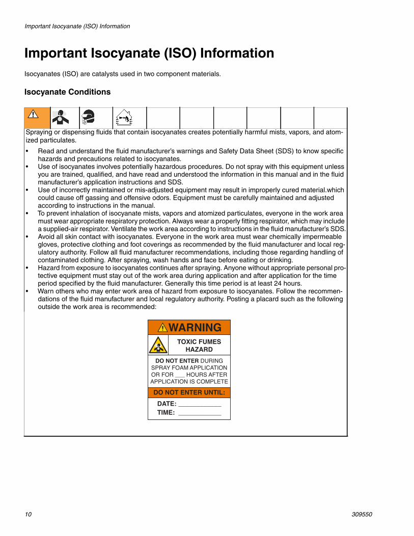
Isocyanate Conditions
Spraying or dispensing fluids that contain isocyanates creates potentially harmful mists, vapors, and atom-ized particulates.
• Read and understand the fluid manufacturer’s warnings and Safety Data Sheet (SDS) to know specifichazards and precautions related to isocyanates.
• Use of isocyanates involves potentially hazardous procedures. Do not spray with this equipment unlessyou are trained, qualified, and have read and understood the information in this manual and in the fluidmanufacturer’s application instructions and SDS.
• Use of incorrectly maintained or mis-adjusted equipment may result in improperly cured material.whichcould cause off gassing and offensive odors. Equipment must be carefully maintained and adjustedaccording to instructions in the manual.
• To prevent inhalation of isocyanate mists, vapors and atomized particulates, everyone in the work areamust wear appropriate respiratory protection. Always wear a properly fitting respirator, which may includea supplied-air respirator. Ventilate the work area according to instructions in the fluid manufacturer’s SDS.
• Avoid all skin contact with isocyanates. Everyone in the work area must wear chemically impermeablegloves, protective clothing and foot coverings as recommended by the fluid manufacturer and local reg-ulatory authority. Follow all fluid manufacturer recommendations, including those regarding handling ofcontaminated clothing. After spraying, wash hands and face before eating or drinking.
• Hazard from exposure to isocyanates continues after spraying. Anyone without appropriate personal pro-tective equipment must stay out of the work area during application and after application for the timeperiod specified by the fluid manufacturer. Generally this time period is at least 24 hours.
• Warn others who may enter work area of hazard from exposure to isocyanates. Follow the recommen-dations of the fluid manufacturer and local regulatory authority. Posting a placard such as the followingoutside the work area is recommended:
TOXIC FUMESHAZARD
DO NOT ENTER DURINGSPRAY FOAM APPLICATIONOR FOR ___ HOURS AFTERAPPLICATION IS COMPLETE
DO NOT ENTER UNTIL:
DATE:TIME:
________________________
Important Isocyanate (ISO) Information
309550 11
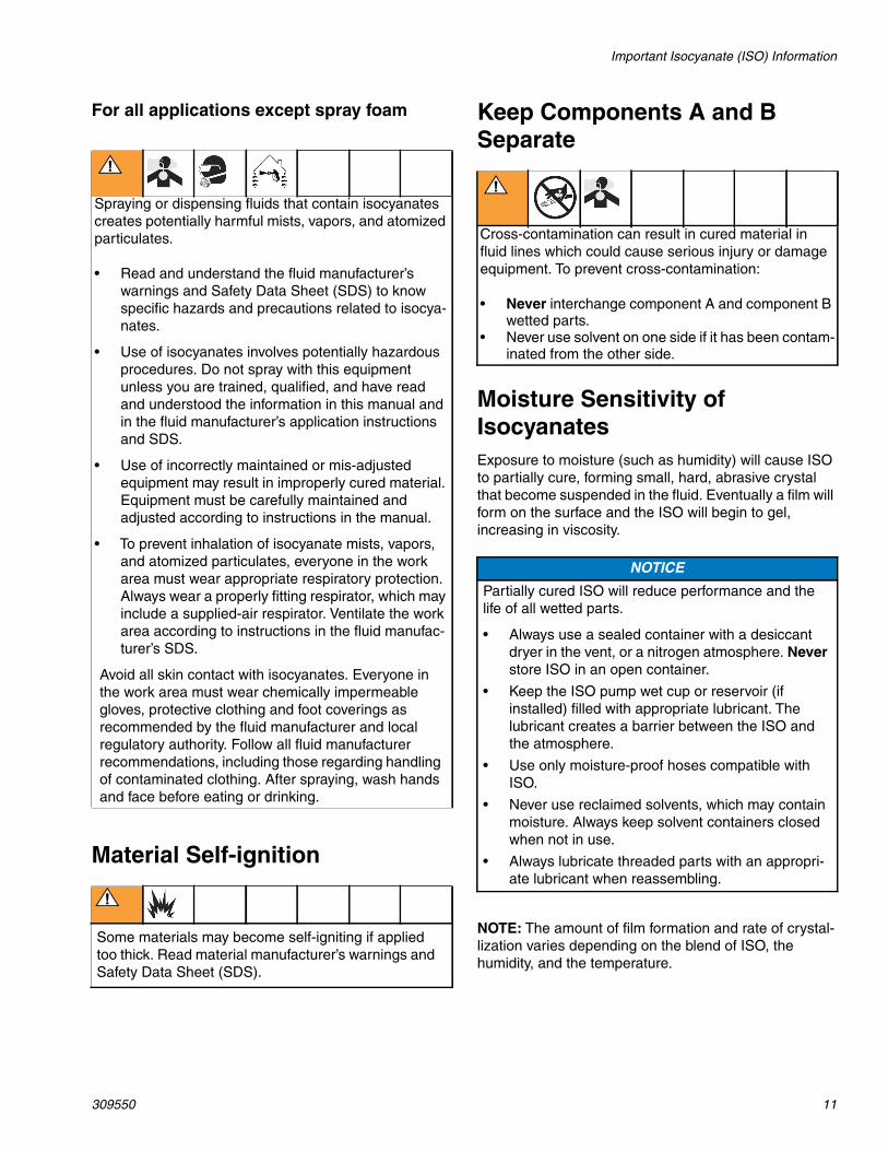
For all applications except spray foam
Material Self-ignition
Keep Components A and BSeparate
Moisture Sensitivity ofIsocyanatesExposure to moisture (such as humidity) will cause ISOto partially cure, forming small, hard, abrasive crystalthat become suspended in the fluid. Eventually a film willform on the surface and the ISO will begin to gel,increasing in viscosity.
NOTE: The amount of film formation and rate of crystal-lization varies depending on the blend of ISO, thehumidity, and the temperature.
Spraying or dispensing fluids that contain isocyanatescreates potentially harmful mists, vapors, and atomizedparticulates.
• Read and understand the fluid manufacturer’swarnings and Safety Data Sheet (SDS) to knowspecific hazards and precautions related to isocya-nates.
• Use of isocyanates involves potentially hazardousprocedures. Do not spray with this equipmentunless you are trained, qualified, and have readand understood the information in this manual andin the fluid manufacturer’s application instructionsand SDS.
• Use of incorrectly maintained or mis-adjustedequipment may result in improperly cured material.Equipment must be carefully maintained andadjusted according to instructions in the manual.
• To prevent inhalation of isocyanate mists, vapors,and atomized particulates, everyone in the workarea must wear appropriate respiratory protection.Always wear a properly fitting respirator, which mayinclude a supplied-air respirator. Ventilate the workarea according to instructions in the fluid manufac-turer’s SDS.
Avoid all skin contact with isocyanates. Everyone inthe work area must wear chemically impermeablegloves, protective clothing and foot coverings asrecommended by the fluid manufacturer and localregulatory authority. Follow all fluid manufacturerrecommendations, including those regarding handlingof contaminated clothing. After spraying, wash handsand face before eating or drinking.
Some materials may become self-igniting if appliedtoo thick. Read material manufacturer’s warnings andSafety Data Sheet (SDS).
Cross-contamination can result in cured material influid lines which could cause serious injury or damageequipment. To prevent cross-contamination:
• Never interchange component A and component Bwetted parts.
• Never use solvent on one side if it has been contam-inated from the other side.
NOTICE
Partially cured ISO will reduce performance and thelife of all wetted parts.
• Always use a sealed container with a desiccantdryer in the vent, or a nitrogen atmosphere. Neverstore ISO in an open container.
• Keep the ISO pump wet cup or reservoir (ifinstalled) filled with appropriate lubricant. Thelubricant creates a barrier between the ISO andthe atmosphere.
• Use only moisture-proof hoses compatible withISO.
• Never use reclaimed solvents, which may containmoisture. Always keep solvent containers closedwhen not in use.
• Always lubricate threaded parts with an appropri-ate lubricant when reassembling.

Grounding
12 309550
Foam Resins with 245 faBlowing AgentsSome foam blowing agents will froth at temperaturesabove 90°F (33°C) when not under pressure, especiallyif agitated. To reduce frothing, minimize preheating in acirculation system.
Changing Materials
Grounding
Check your local electrical code and proportioner man-ual for detailed grounding instructions.
Ground the spray gun through connection to aGraco-approved grounded fluid supply hose.
Piston Safety LockEngage piston safety lock whenever you stop spray-ing, to avoid accidental triggering.
NOTICE
Changing the material types used in your equipmentrequires special attention to avoid equipment damageand downtime.
• When changing materials, flush the equipmentmultiple times to ensure it is thoroughly clean.
• Always clean the fluid inlet strainers after flushing.
• Check with your material manufacturer for chemi-cal compatibility.
• When changing between epoxies and urethanesor polyureas, disassemble and clean all fluid com-ponents and change hoses. Epoxies often haveamines on the B (hardener) side. Polyureas oftenhave amines on the B (resin) side.
WARNING
Read warnings, page 8.
WARNING
Read warnings, page 7.
To engage piston safety lock: push knob in and turnclockwise. If engaged, gun will not actuate.
To disengage piston safety lock: push knob in andturn counterclockwise until it pops out. There will be agap between knob and gun body.
TI2409A
Engaged
TI2410A
Disengaged
Turning Air Cap
309550 13
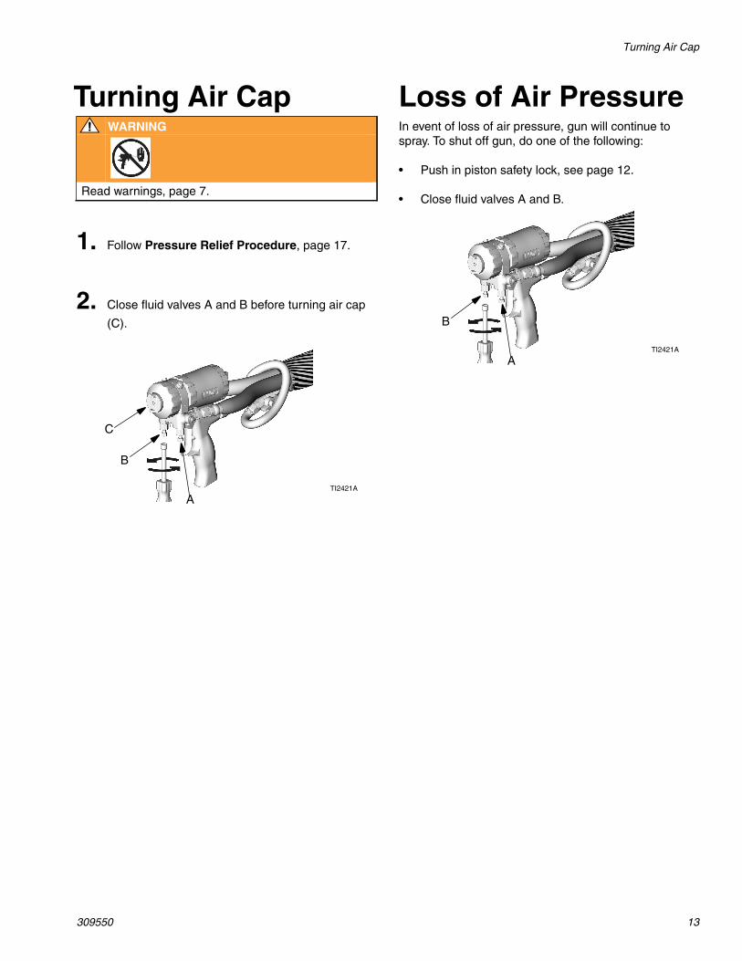
Turning Air Cap Loss of Air PressureIn event of loss of air pressure, gun will continue tospray. To shut off gun, do one of the following:
• Push in piston safety lock, see page 12.
• Close fluid valves A and B.
WARNING
Read warnings, page 7.
1. Follow Pressure Relief Procedure, page 17.
2. Close fluid valves A and B before turning air cap
(C).
TI2421A
C
B
A
TI2421A
B
A
Setup
14 309550
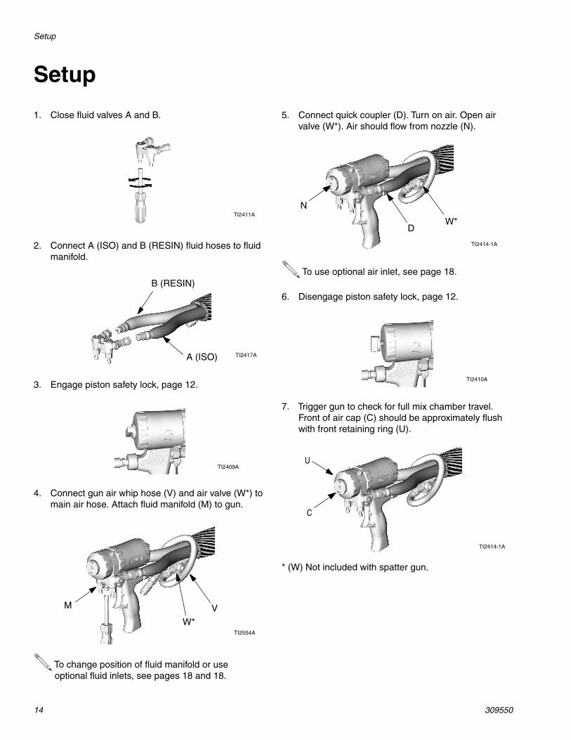
Setup
* (W) Not included with spatter gun.
1. Close fluid valves A and B.
2. Connect A (ISO) and B (RESIN) fluid hoses to fluidmanifold.
3. Engage piston safety lock, page 12.
4. Connect gun air whip hose (V) and air valve (W*) tomain air hose. Attach fluid manifold (M) to gun.
To change position of fluid manifold or useoptional fluid inlets, see pages 18 and 18.
TI2411A
A (ISO)
B (RESIN)
TI2417A
TI2409A
TI2554A
VM
W*
5. Connect quick coupler (D). Turn on air. Open airvalve (W*). Air should flow from nozzle (N).
To use optional air inlet, see page 18.
6. Disengage piston safety lock, page 12.
7. Trigger gun to check for full mix chamber travel.Front of air cap (C) should be approximately flushwith front retaining ring (U).
TI2414-1A
D
N
W*
TI2410A
TI2414-1A
C
U
Setup
309550 15
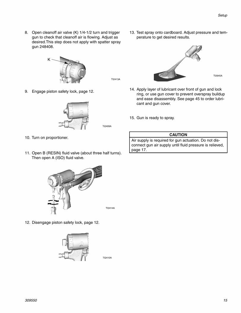
8. Open cleanoff air valve (K) 1/4-1/2 turn and triggergun to check that cleanoff air is flowing. Adjust asdesired.This step does not apply with spatter spraygun 248408.
9. Engage piston safety lock, page 12.
10. Turn on proportioner.
11. Open B (RESIN) fluid valve (about three half turns).Then open A (ISO) fluid valve.
12. Disengage piston safety lock, page 12.
K
TI2413A
TI2409A
TI2414A
TI2410A
13. Test spray onto cardboard. Adjust pressure and tem-perature to get desired results.
14. Apply layer of lubricant over front of gun and lockring, or use gun cover to prevent overspray buildupand ease disassembly. See page 45 to order lubri-cant and gun cover.
15. Gun is ready to spray.
CAUTIONAir supply is required for gun actuation. Do not dis-connect gun air supply until fluid pressure is relieved,page 17.
TI2645A
Shutdown
16 309550
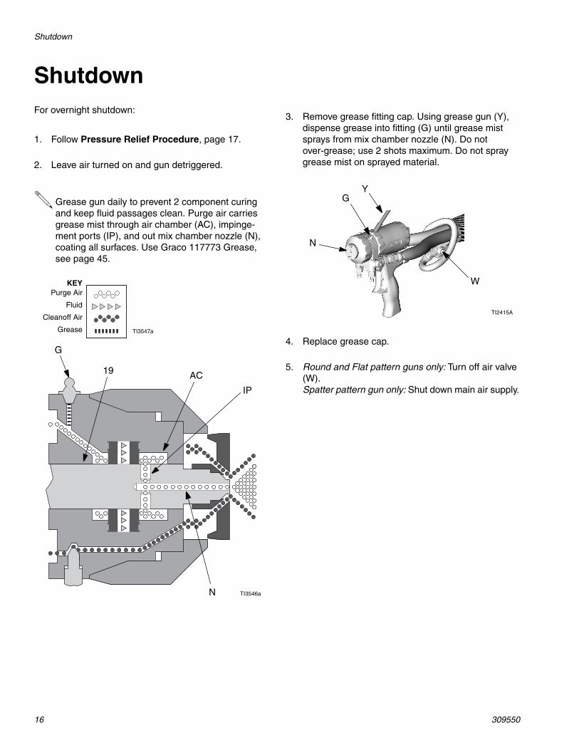
ShutdownFor overnight shutdown:
1. Follow Pressure Relief Procedure, page 17.
2. Leave air turned on and gun detriggered.
Grease gun daily to prevent 2 component curingand keep fluid passages clean. Purge air carriesgrease mist through air chamber (AC), impinge-ment ports (IP), and out mix chamber nozzle (N),coating all surfaces. Use Graco 117773 Grease,see page 45.
TI3546a
TI3547a
19 AC
IP
N
G
KEYPurge Air
Fluid
Cleanoff Air
Grease
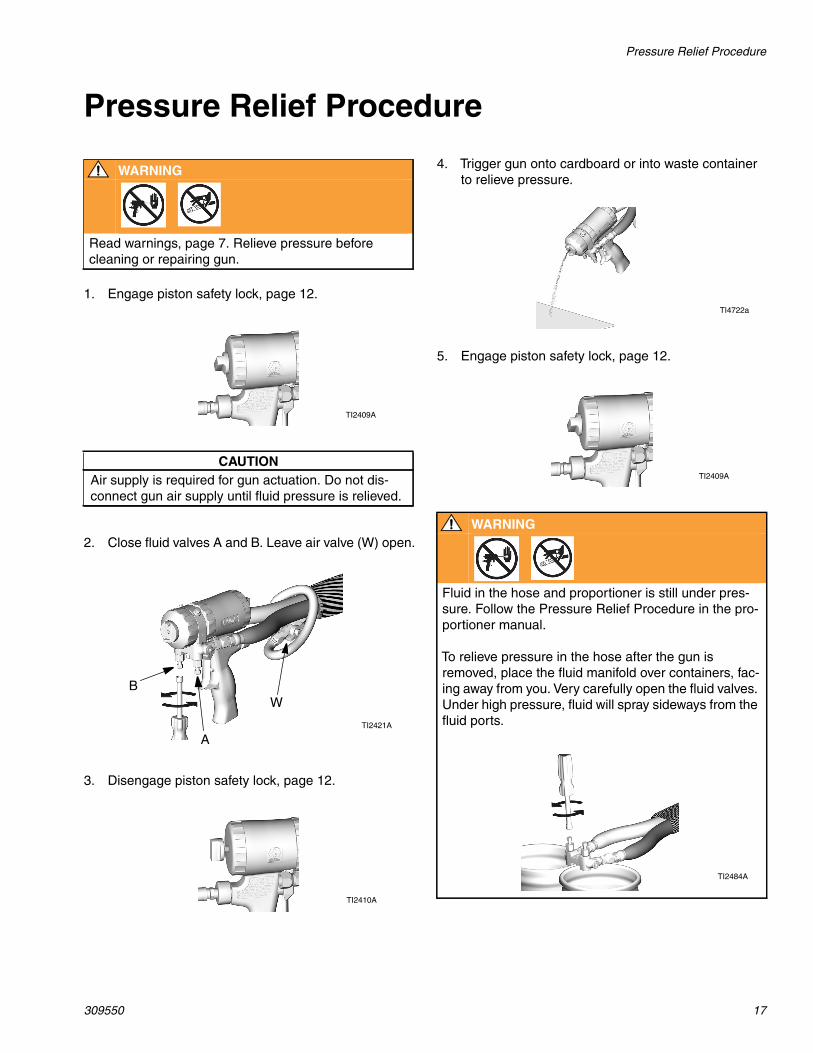
3. Remove grease fitting cap. Using grease gun (Y),dispense grease into fitting (G) until grease mistsprays from mix chamber nozzle (N). Do notover-grease; use 2 shots maximum. Do not spraygrease mist on sprayed material.
4. Replace grease cap.
5. Round and Flat pattern guns only: Turn off air valve(W).Spatter pattern gun only: Shut down main air supply.
GY
N
TI2415A
W
Pressure Relief Procedure
309550 17
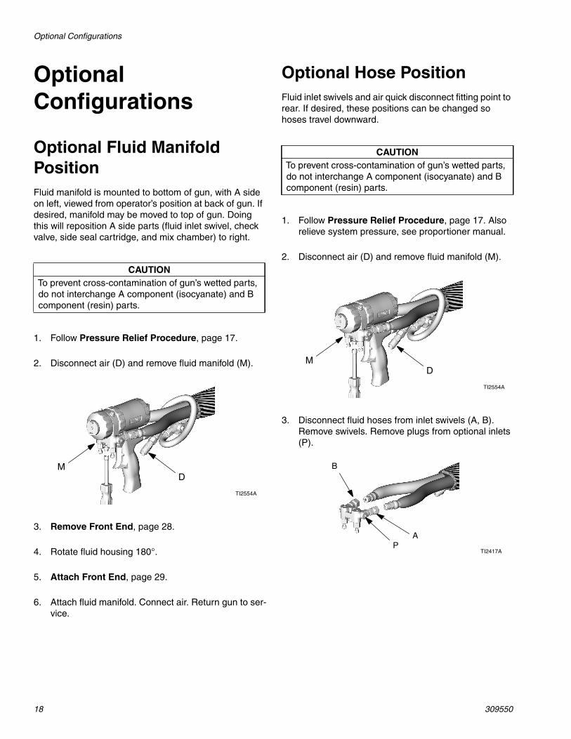
Pressure Relief Procedure
WARNING
Read warnings, page 7. Relieve pressure beforecleaning or repairing gun.
1. Engage piston safety lock, page 12.
CAUTIONAir supply is required for gun actuation. Do not dis-connect gun air supply until fluid pressure is relieved.
2. Close fluid valves A and B. Leave air valve (W) open.
3. Disengage piston safety lock, page 12.
TI2409A
TI2421A
A
BW
TI2410A
4. Trigger gun onto cardboard or into waste containerto relieve pressure.
5. Engage piston safety lock, page 12.
WARNING
Fluid in the hose and proportioner is still under pres-sure. Follow the Pressure Relief Procedure in the pro-portioner manual.
To relieve pressure in the hose after the gun isremoved, place the fluid manifold over containers, fac-ing away from you. Very carefully open the fluid valves.Under high pressure, fluid will spray sideways from thefluid ports.
TI4722a
TI2409A
TI2484A
Optional Configurations
18 309550
OptionalConfigurations
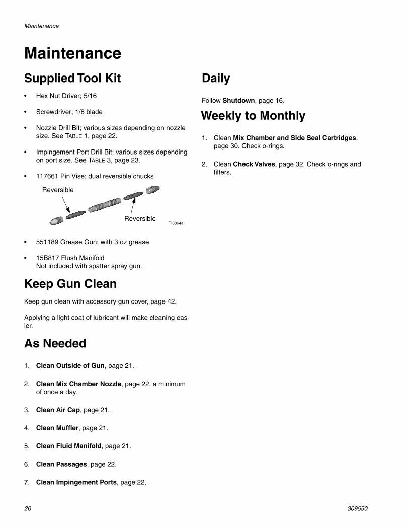
Optional Fluid ManifoldPositionFluid manifold is mounted to bottom of gun, with A sideon left, viewed from operator’s position at back of gun. Ifdesired, manifold may be moved to top of gun. Doingthis will reposition A side parts (fluid inlet swivel, checkvalve, side seal cartridge, and mix chamber) to right.
Optional Hose PositionFluid inlet swivels and air quick disconnect fitting point torear. If desired, these positions can be changed sohoses travel downward.
CAUTIONTo prevent cross-contamination of gun’s wetted parts,do not interchange A component (isocyanate) and Bcomponent (resin) parts.
1. Follow Pressure Relief Procedure, page 17.
2. Disconnect air (D) and remove fluid manifold (M).
3. Remove Front End, page 28.
4. Rotate fluid housing 180°.
5. Attach Front End, page 29.
6. Attach fluid manifold. Connect air. Return gun to ser-vice.
TI2554A
MD
CAUTIONTo prevent cross-contamination of gun’s wetted parts,do not interchange A component (isocyanate) and Bcomponent (resin) parts.
1. Follow Pressure Relief Procedure, page 17. Alsorelieve system pressure, see proportioner manual.
2. Disconnect air (D) and remove fluid manifold (M).
3. Disconnect fluid hoses from inlet swivels (A, B).Remove swivels. Remove plugs from optional inlets(P).
TI2554A
MD
TI2417AP
A
B

Flat Spray Tips
309550 19
Flat Spray Tips4. Apply thread sealant to plugs (12c), elbows (50*),and male threads of swivels (A, B). Install elbows(50*) in optional inlets (P), facing down. Install swiv-els (A, B) in elbows. Be sure to install A swivel(smaller) in A side. Install plugs where swivels hadbeen. Torque all parts to 235-245 in-lb (26.6-27.7N•m).
5. Connect A and B hoses to A and B swivels.
6. Remove fitting (D) and plug (J). Reverse positions.Apply thread sealant and torque to 125-135 in-lb(14-15 N•m).
7. Attach fluid manifold. Connect air. Return gun to ser-vice.
TI2646A
50*B
P A
12c
Elbows (50*) are not included with spatter spraygun.
TI2540A
J
D
1. Follow Pressure Relief Procedure, page 17.
2. Remove air cap (10) and flat spray tip (39). Inspecto-ring (40).
If tip is stuck, pry off with small screwdriver or pulloff with pliers. Tip is hardened to resist damage.
3. To clean, soak tip in compatible solvent, see page21. Clean gently with tip cleanout tool 15D234, page45, to fit tip configuration.
4. Reposition tip horizontally or vertically, or install dif-ferent tip size.
Tips marked on back with last 3 digits of part no.See Flat Tip Part No. Reference Guide, page40.
5. Reinstall air cap hand tight. Cleaning hole alignmentto tip not important.
TI2557A
1039
40
TI2649A
TI2648A
Maintenance
20 309550
MaintenanceSupplied Tool Kit• Hex Nut Driver; 5/16
• Screwdriver; 1/8 blade
• Nozzle Drill Bit; various sizes depending on nozzlesize. See TABLE 1, page 22.
• Impingement Port Drill Bit; various sizes dependingon port size. See TABLE 3, page 23.
• 117661 Pin Vise; dual reversible chucks
• 551189 Grease Gun; with 3 oz grease
• 15B817 Flush ManifoldNot included with spatter spray gun.
Keep Gun CleanKeep gun clean with accessory gun cover, page 42.
Applying a light coat of lubricant will make cleaning eas-ier.
As Needed
Daily
Weekly to Monthly
1. Clean Outside of Gun, page 21.
2. Clean Mix Chamber Nozzle, page 22, a minimumof once a day.
3. Clean Air Cap, page 21.
4. Clean Muffler, page 21.
5. Clean Fluid Manifold, page 21.
6. Clean Passages, page 22.
7. Clean Impingement Ports, page 22.
TI3864a
Reversible
Reversible
Follow Shutdown, page 16.
1. Clean Mix Chamber and Side Seal Cartridges,page 30. Check o-rings.
2. Clean Check Valves, page 32. Check o-rings andfilters.
Maintenance
309550 21
Flush GunIf it is necessary to flush gun, use following procedure.
Clean Outside of GunWipe off outside of gun with compatible solvent.
Use N Methyl Pyrrolidone (NMP), Dynasolve CU-6,Dzolv, or equivalent to soften cured material.
Clean Air CapSoak air cap in compatible solvent. Clean holes with #58(.042) drill bit.
Clean MufflerRemove and clean muffler with compatible solvent.
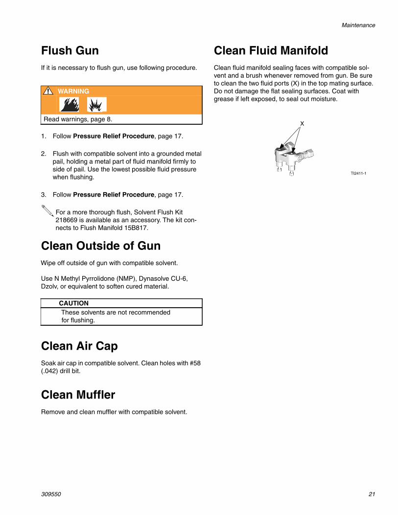
Clean Fluid ManifoldClean fluid manifold sealing faces with compatible sol-vent and a brush whenever removed from gun. Be sureto clean the two fluid ports (X) in the top mating surface.Do not damage the flat sealing surfaces. Coat withgrease if left exposed, to seal out moisture.
WARNING
Read warnings, page 8.
1. Follow Pressure Relief Procedure, page 17.
2. Flush with compatible solvent into a grounded metalpail, holding a metal part of fluid manifold firmly toside of pail. Use the lowest possible fluid pressurewhen flushing.
3. Follow Pressure Relief Procedure, page 17.
For a more thorough flush, Solvent Flush Kit218669 is available as an accessory. The kit con-nects to Flush Manifold 15B817.
CAUTIONThese solvents are not recommendedfor flushing.
X
TI2411-1
Maintenance
22 309550
Clean Mix Chamber Nozzle
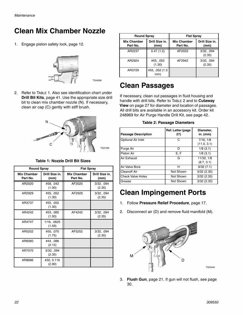
Clean PassagesIf necessary, clean out passages in fluid housing andhandle with drill bits. Refer to TABLE 2 and to CutawayView on page 27 for diameter and location of passages.All drill bits are available in an accessory kit. Order kit248969 for Air Purge Handle Drill Kit, see page 42.
Clean Impingement Ports
1. Engage piston safety lock, page 12.
2. Refer to TABLE 1. Also see identification chart underDrill Bit Kits, page 41. Use the appropriate size drillbit to clean mix chamber nozzle (N). If necessary,clean air cap (C) gently with stiff brush.
Table 1: Nozzle Drill Bit Sizes
Round Spray Flat Spray
Mix ChamberPart No.
Drill Size in.(mm)
Mix ChamberPart No.
Drill Size in.(mm)
AR2020 #58, .042(1.00)
AF2020 3/32, .094(2.35)
AR2929 #55, .052(1.30)
AF2929 3/32, .094(2.35)
AR3737 #55, .052(1.30)
AR4242 #53, .060(1.50)
AF4242 3/32, .094(2.35)
AR4747 1/16, .0625(1.59)
AR5252 #50, .070(1.75)
AF5252 3/32, .094(2.35)
AR6060 #44, .086(2.15)
AR7070 3/32, .094(2.35)
AR8686 #32, 0.116(2.90)
TI2409A
N
TI2418AC
Round Spray Flat Spray
Mix ChamberPart No.
Drill Size in.(mm)
Mix ChamberPart No.
Drill Size in.(mm)
AR2237 0.47 (1.2) AF2033 3/32, .094(2.35)
AR2924 #55, .052(1.30)
AF2942 3/32, .094(2.35)
AR3729 #55, .052 (1.3mm)
Table 2: Passage Diameters
Passage DescriptionRef. Letter (page
27)Diameter,in. (mm)
Optional Air Inlet C 7/16, 1/8(11.0, 3.1)
Purge Air D 1/8 (3.1)
Piston Air E, F 1/8 (3.1)
Air Exhaust G 11/32, 1/8(8.7, 3.1)
Air Valve Bore H 9/32 (7.1)
Cleanoff Air Not Shown 3/32 (2.35)
Check Valve Holes Not Shown 3/32 (2.35)
Grease Not Shown 3/32 (2.35)
1. Follow Pressure Relief Procedure, page 17.
2. Disconnect air (D) and remove fluid manifold (M).
3. Flush Gun, page 21. If gun will not flush, see page30.
TI2554A
MD
Maintenance
309550 23
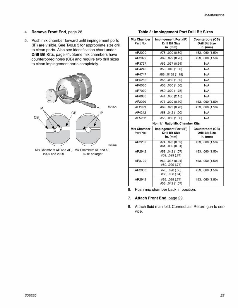
4. Remove Front End, page 28.
5. Push mix chamber forward until impingement ports(IP) are visible. See TABLE 3 for appropriate size drillto clean ports. Also see identification chart underDrill Bit Kits, page 41. Some mix chambers havecounterbored holes (CB) and require two drill sizesto clean impingement ports completely.
TI2420AIP
CBIP
TI3533a
Mix Chambers AR and AF,2020 and 2929
Mix Chambers AR and AF,4242 or larger
CB
Table 3: Impingement Port Drill Bit Sizes
Mix ChamberPart No.
Impingement Port (IP)Drill Bit Size
in. (mm)
Counterbore (CB)Drill Bit Size
in. (mm)
AR2020 #76, .020 (0.50) #53, .060 (1.50)
AR2929 #69, .029 (0.70) #53, .060 (1.50)
AR3737 #63, .037 (0.94) N/A
AR4242 #58, .042 (1.00) N/A
AR4747 #56, .0165 (1.18) N/A
AR5252 #55, .052 (1.30) N/A
AR6060 #53, .060 (1.50) N/A
AR7070 #50, .070 (1.75) N/A
AR8686 #44, .086 (2.15) N/A
AF2020 #76, .020 (0.50) #53, .060 (1.50)
AF2929 #69, .029 (0.70) #53, .060 (1.50)
AF4242 #58, .042 (1.00) N/A
AF5252 #55, .052 (1.30) N/A
Non 1:1 Ratio Mix Chamber Kits
Mix ChamberPart No.
Impingement Port (IP)Drill Bit Size
in. (mm)
Counterbore (CB)Drill Bit Size
in. (mm)
AR2232 #74, .023 (0.59)#61, .032 (0.81)
#53, .060 (1.50)
AR2942 #58, .042 (1.07)#69, .029 (.74)
#53, .060 (1.50)
AR3729 #63, .037 (0.94)#69, .029 (.74)
#53, .060 (1.50)
AR2033 #76, .020 (.50)#66, .033 (.84)
#53, .060 (1.50)
AR2942 #69, .029 (.74)#58, .042 (1.07)
#53, .060 (1.50)
6. Push mix chamber back in position.
7. Attach Front End, page 29.
8. Attach fluid manifold. Connect air. Return gun to ser-vice.

Troubleshooting
24 309550
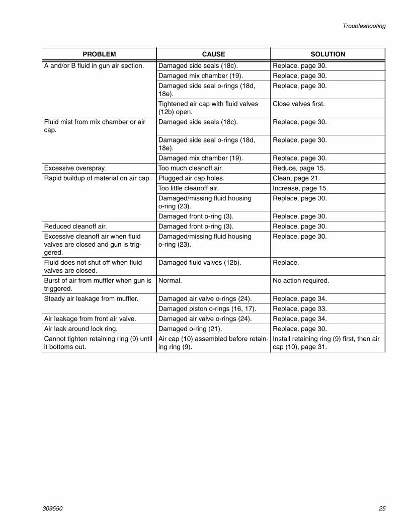
Troubleshooting
1. Follow Pressure Relief Procedure, page 17, beforechecking or repairing gun.
2. Check all possible problems and causes before dis-assembling gun.
CAUTIONTo prevent cross-contamination of the gun’s wettedparts, do not interchange A component (isocyanate)and B component (resin) parts.
PROBLEM CAUSE SOLUTION
Gun does not fully actuate when trig-gered.
Safety lock engaged. Disengage safety lock, page 12.
Plugged muffler (22). Clean, page 21.
Damaged air valve o-rings (24). Replace, page 34.
Fluid does not spray when gun is fullyactuated.
Closed fluid valves (12b). Open.
Plugged impingement ports. Clean, page 22.
Plugged check valves (26). Clean, page 32.
Gun actuates slowly. Plugged muffler (22). Clean, page 21.
Damaged piston o-rings (16, 17). Replace, page 33.
Dirty air valve, or damaged o-rings(24).
Clean air valve or replace o-rings,page 34.
Gun delays, then actuates abruptly. Cured material around side seals(18).
Inspect side seals (18c) and mixchamber (19) for scratches. Replace,page 30.
Retaining ring (9) not bottomed out. Tighten retaining ring until bottomedout.
Loss of round pattern. Dirty mix chamber nozzle. Clean, page 22.
Loss of flat pattern. Plugged spray tip. Clean in compatible solvent, page19.
Worn tip. Replace, page 19.
Dirty mix chamber nozzle. Clean, page 22.
Leakage between flat tip and mixchamber.
Tip not seated properly. Reassemble, page 19.
Damaged/missing o-ring (40). Replace, page 19.
Pressure imbalance. Plugged impingement ports. Clean, page 22.
Plugged check valves (26). Clean, page 32.
Viscosities not equal. Adjust temperature to compensate.
Troubleshooting
309550 25
A and/or B fluid in gun air section. Damaged side seals (18c). Replace, page 30.
Damaged mix chamber (19). Replace, page 30.
Damaged side seal o-rings (18d,18e).
Replace, page 30.
Tightened air cap with fluid valves(12b) open.
Close valves first.
Fluid mist from mix chamber or aircap.
Damaged side seals (18c). Replace, page 30.
Damaged side seal o-rings (18d,18e).
Replace, page 30.
Damaged mix chamber (19). Replace, page 30.
Excessive overspray. Too much cleanoff air. Reduce, page 15.
Rapid buildup of material on air cap. Plugged air cap holes. Clean, page 21.
Too little cleanoff air. Increase, page 15.
Damaged/missing fluid housingo-ring (23).
Replace, page 30.
Damaged front o-ring (3). Replace, page 30.
Reduced cleanoff air. Damaged front o-ring (3). Replace, page 30.
Excessive cleanoff air when fluidvalves are closed and gun is trig-gered.
Damaged/missing fluid housingo-ring (23).
Replace, page 30.
Fluid does not shut off when fluidvalves are closed.
Damaged fluid valves (12b). Replace.
Burst of air from muffler when gun istriggered.
Normal. No action required.
Steady air leakage from muffler. Damaged air valve o-rings (24). Replace, page 34.
Damaged piston o-rings (16, 17). Replace, page 33.
Air leakage from front air valve. Damaged air valve o-rings (24). Replace, page 34.
Air leak around lock ring. Damaged o-ring (21). Replace, page 30.
Cannot tighten retaining ring (9) untilit bottoms out.
Air cap (10) assembled before retain-ing ring (9).
Install retaining ring (9) first, then aircap (10), page 31.
PROBLEM CAUSE SOLUTION

Troubleshooting
26 309550
Theory of Operation
Gun Triggered (Fluid Spraying)
Mix chamber (19) moves back, shutting off purge airflow. Impingement ports (IP) align with fluid ports of sideseals (18c), allowing fluid to flow through mix chambernozzle (N).
See page 15 to adjust cleanoff air valve (K).
Gun Detriggered (Air Purging)
Mix chamber (19) moves forward, shutting off fluid flow.Impingement ports (IP) open to air chamber (AC), allow-ing purge air to flow through mix chamber nozzle (N).
See page 16 for use of grease fitting (G).
TI3545a
19 18c
IP
NK
TI3547a
KEYPurge Air
Fluid
Cleanoff Air
Grease
Flow paths are not shown to scale, for clarity.
TI3546a
19 AC
IP
N
G
TI3547a
KEYPurge Air
Fluid
Cleanoff Air
Grease
Flow paths are not shown to scale, for clarity.

Troubleshooting
309550 27
Cutaway View
819 17 15
16
24
10
23
21
24
14 4
26
18 (A Side)B Side not shown
12b
22
CG
D E F
3
H
Repair
28 309550
Repair
Tools RequiredTools needed for complete gun repair:
• adjustable wrench• flat head screwdriver (included)• 1/8 in. (3 mm) diameter rod• 5/16 hex nut driver (included)
LubricationLiberally lubricate all o-rings, seals, and threads. Lubri-cate threads and outside of lock ring (11). See page 45to order lubricant.
Remove Front End
WARNING
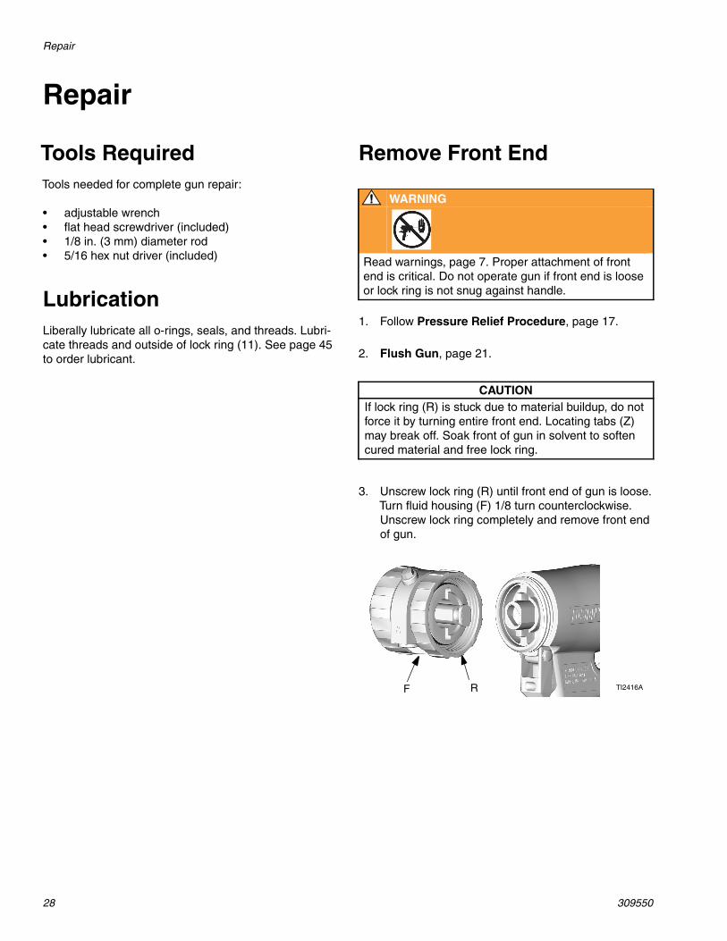
Read warnings, page 7. Proper attachment of frontend is critical. Do not operate gun if front end is looseor lock ring is not snug against handle.
1. Follow Pressure Relief Procedure, page 17.
2. Flush Gun, page 21.
CAUTIONIf lock ring (R) is stuck due to material buildup, do notforce it by turning entire front end. Locating tabs (Z)may break off. Soak front of gun in solvent to softencured material and free lock ring.
3. Unscrew lock ring (R) until front end of gun is loose.Turn fluid housing (F) 1/8 turn counterclockwise.Unscrew lock ring completely and remove front endof gun.
TI2416AF R

Repair
309550 29
Attach Front End
WARNING
Read warnings, page 7. Proper attachment of frontend is critical. Do not operate gun if front end is looseor lock ring is not snug against handle.
1. Engage piston safety lock, page 12.
2. Push on air cap (C) until it is flush with front of gun.This ensures that mix chamber is all the way back.
3. Check that o-ring (21) is in position. Liberally lubri-cate o-ring, threads of lock ring (R) and handle (H),and outside of lock ring. Orient front end (F) asrequired for desired fluid manifold mounting (bottommounting is shown). Insert keyed end (W) of mixchamber in socket (X). Screw lock ring onto handleas far as possible by hand.
TI2409A
C
TI2422A
TI2416A
W X
R H
Y Z
F 21
4. Turn fluid housing 1/8 turn clockwise to engage slots(Y) and tabs (Z). Push on front end to ensure it isproperly seated. Continue screwing lock ring (R)onto handle (H) very securely. When properlyassembled, lock ring is snug against handle.
R H
TI2423A
Repair
30 309550
Mix Chamber and Side SealCartridgesSee page 3 for available mix chamber sizes.
Continued on page 31.
1. Follow Pressure Relief Procedure, page 17.
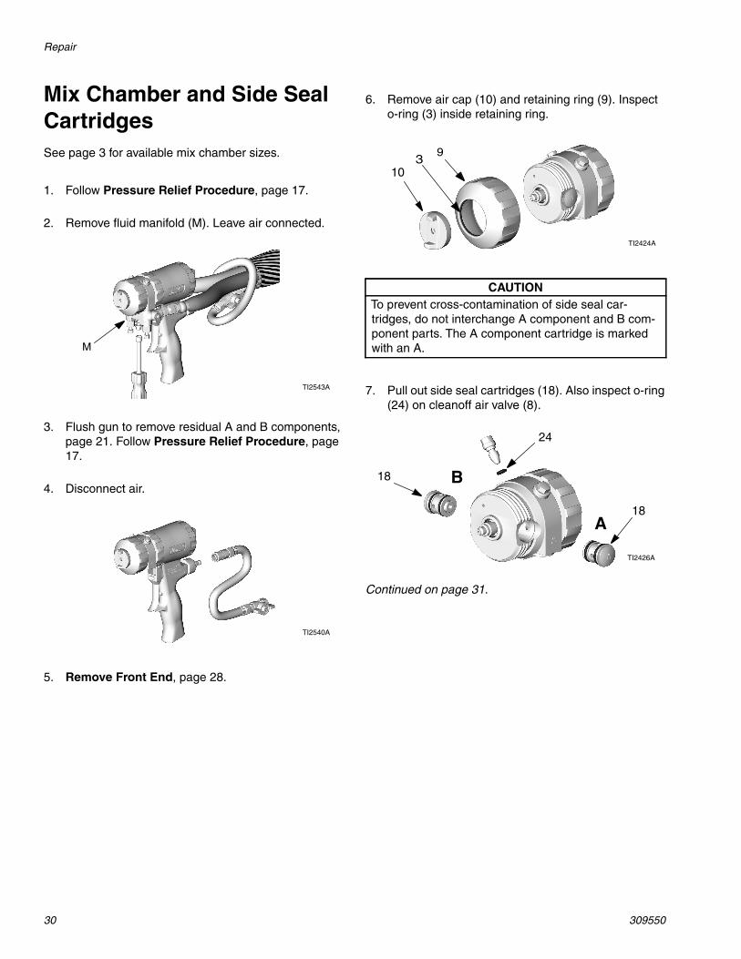
2. Remove fluid manifold (M). Leave air connected.
3. Flush gun to remove residual A and B components,page 21. Follow Pressure Relief Procedure, page17.
4. Disconnect air.
5. Remove Front End, page 28.
TI2543A
M
TI2540A
6. Remove air cap (10) and retaining ring (9). Inspecto-ring (3) inside retaining ring.
CAUTIONTo prevent cross-contamination of side seal car-tridges, do not interchange A component and B com-ponent parts. The A component cartridge is markedwith an A.
7. Pull out side seal cartridges (18). Also inspect o-ring(24) on cleanoff air valve (8).
9
TI2424A
103
24
18
18
B
A
TI2426A
Repair
309550 31
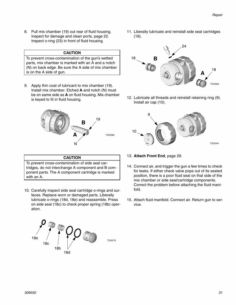
8. Pull mix chamber (19) out rear of fluid housing.Inspect for damage and clean ports, page 22.Inspect o-ring (23) in front of fluid housing.
CAUTIONTo prevent cross-contamination of the gun’s wettedparts, mix chamber is marked with an A and a notch(N) on back edge. Be sure the A side of mix chamberis on the A side of gun.
9. Apply thin coat of lubricant to mix chamber (19).Install mix chamber. Etched A and notch (N) mustbe on same side as A on fluid housing. Mix chamberis keyed to fit in fluid housing.
CAUTIONTo prevent cross-contamination of side seal car-tridges, do not interchange A component and B com-ponent parts. The A component cartridge is markedwith an A.
10. Carefully inspect side seal cartridge o-rings and sur-faces. Replace worn or damaged parts. Liberallylubricate o-rings (18d, 18e) and reassemble. Presson side seal (18c) to check proper spring (18b) oper-ation.
B
A TI2428A
19
N
TI2427A18e
18c
18d18b
11. Liberally lubricate and reinstall side seal cartridges(18).
12. Lubricate all threads and reinstall retaining ring (9).Install air cap (10).
13. Attach Front End, page 29.
14. Connect air, and trigger the gun a few times to checkfor leaks. If either check valve pops out of its seatedposition, there is a poor fluid seal on that side of themix chamber or side seal/cartridge components.Correct the problem before attaching the fluid mani-fold.
15. Attach fluid manifold. Connect air. Return gun to ser-vice.
24
18
18
B
A
TI2426A
TI2424A
9
10
Repair
32 309550
Check Valves
Before disassembling, press on ball (26c) to testcheck valve for proper movement and springaction.
1. Follow Pressure Relief Procedure, page 17.
2. Remove fluid manifold (M). Leave air connected.Clean Fluid Manifold, page 21.
3. Flush gun to remove residual A and B components,page 21. Follow Pressure Relief Procedure, page17.
4. Disconnect air.
CAUTIONTo prevent cross-contamination of the check valves,do not interchange A component and B componentparts. The A component check valve is marked withan A.
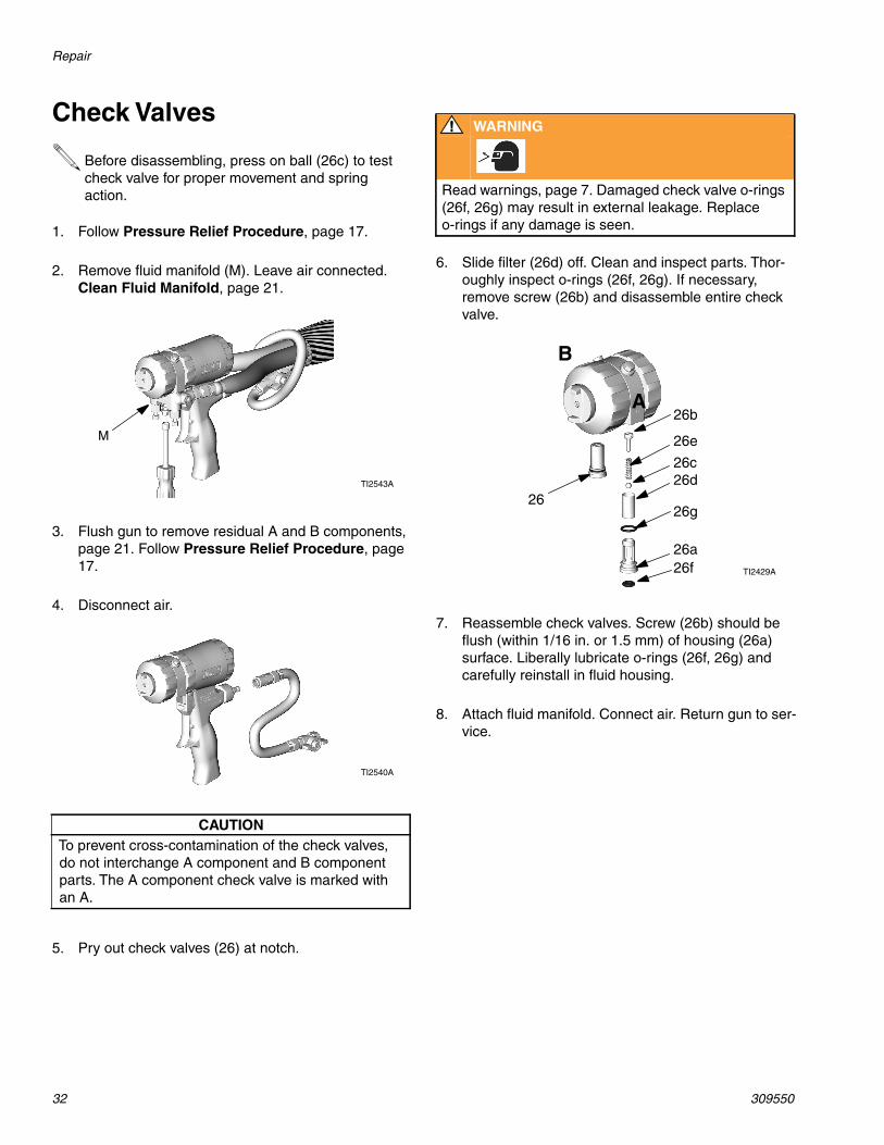
5. Pry out check valves (26) at notch.
TI2543A
M
TI2540A
WARNING
Read warnings, page 7. Damaged check valve o-rings(26f, 26g) may result in external leakage. Replaceo-rings if any damage is seen.
6. Slide filter (26d) off. Clean and inspect parts. Thor-oughly inspect o-rings (26f, 26g). If necessary,remove screw (26b) and disassemble entire checkvalve.
7. Reassemble check valves. Screw (26b) should beflush (within 1/16 in. or 1.5 mm) of housing (26a)surface. Liberally lubricate o-rings (26f, 26g) andcarefully reinstall in fluid housing.
8. Attach fluid manifold. Connect air. Return gun to ser-vice.
26b
26
B
A
26e
26c26d
26g
26a26f TI2429A

Repair
309550 33
Piston
1. Follow Pressure Relief Procedure, page 17.
2. Disconnect air (D) and remove fluid manifold (M).
3. Remove Front End, page 28.
4. Unscrew cylinder cap (5) and inspect o-ring (14).
5. Push piston shaft to remove piston (15). Inspect pis-ton o-ring (16) and shaft o-ring (17).
TI2554A
MD
5
14
TI2430A
16
17
15
TI2431A
6. Liberally lubricate piston o-rings. Reinstall piston.Shaft is keyed for proper assembly. Push firmly toseat piston.
7. Install cylinder cap (5).
8. Attach Front End, page 29.
9. Attach fluid manifold. Connect air. Return gun to ser-vice.
TI2432A
TI2430A
5
Repair
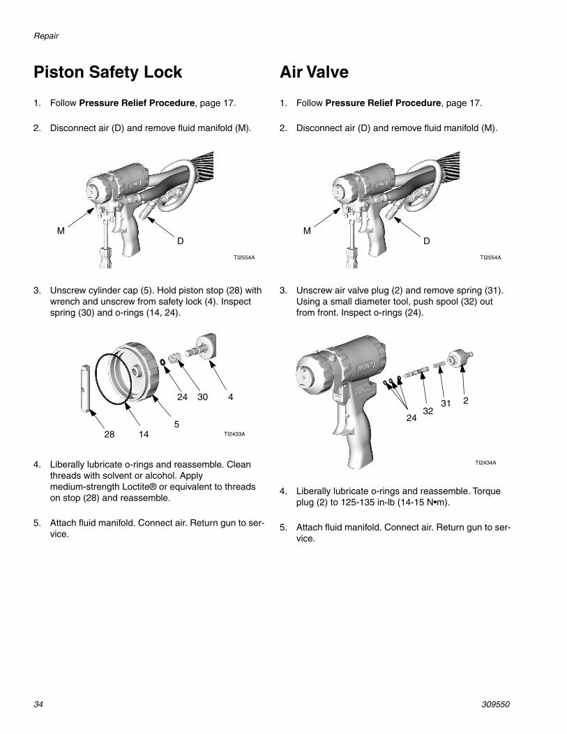
34 309550
Piston Safety Lock Air Valve
1. Follow Pressure Relief Procedure, page 17.
2. Disconnect air (D) and remove fluid manifold (M).
3. Unscrew cylinder cap (5). Hold piston stop (28) withwrench and unscrew from safety lock (4). Inspectspring (30) and o-rings (14, 24).
4. Liberally lubricate o-rings and reassemble. Cleanthreads with solvent or alcohol. Applymedium-strength Loctite® or equivalent to threadson stop (28) and reassemble.
5. Attach fluid manifold. Connect air. Return gun to ser-vice.
TI2554A
MD
51428
24 30 4
TI2433A
1. Follow Pressure Relief Procedure, page 17.
2. Disconnect air (D) and remove fluid manifold (M).
3. Unscrew air valve plug (2) and remove spring (31).Using a small diameter tool, push spool (32) outfrom front. Inspect o-rings (24).
4. Liberally lubricate o-rings and reassemble. Torqueplug (2) to 125-135 in-lb (14-15 N•m).
5. Attach fluid manifold. Connect air. Return gun to ser-vice.
TI2554A
MD
2432
31 2
TI2434A

Notes
309550 35
Notes
Parts
36 309550
Parts
33
430
24514
16 28
1517
‡8‡24
21‡
7‡
27‡
19
3231
2
24
129
6
13
‡25
‡9‡10
23‡*
12a
‡11
22
51
3‡*
‡26b
‡26e
‡26c
‡26d
‡26g
‡26a
‡26f
12c
12f
12e
12b
12d TI2435C
50
49
‡37
47
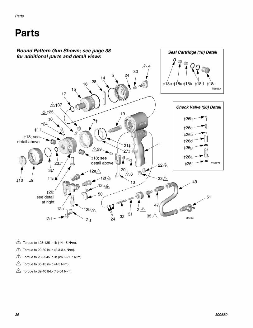
Round Pattern Gun Shown; see page 38for additional parts and detail views
35
3
Torque to 125-135 in-lb (14-15 N•m).
Torque to 20-30 in-lb (2.3-3.4 N•m).
Torque to 235-245 in-lb (26.6-27.7 N•m).
Torque to 35-45 in-lb (4-5 N•m).
Torque to 32-40 ft-lb (43-54 N•m).
1
2
3
4
5
4
3
5
1
1
1
32
2
4
4
4
Check Valve (26) Detail
TI3927A
12g
‡18; seedetail above
‡18; seedetail above
‡26;see detail
at right
20
‡18e ‡18c ‡18b ‡18d ‡18a
Seal Cartridge (18) Detail
TI3926A
11a✖
Parts
309550 37
* These parts are only available in repair kits. Toselect a kit, refer to page 40.
† These parts are not available singly.‡ Included in Front End Replacement Kit 246361.✖ For date code B17 or prior, see manual 310767.★ Included in Safety Stop Assembly 248064 (includes
1 of item 24).▲ Replacement Danger and Warning labels, tags, and
cards are available at no cost.◆ Included in Spatter Tip Kit 248414 (see page 38).
Ref.No. Part No. Description Qty1 15K365 HANDLE 12 15B208 PLUG, air valve 13‡ 248137 O-RING; PTFE; package of 6 14★ 15B206 LOCK, safety 15★ 15B204 CAP, cylinder 16 192272 PIN 17‡ 15B215 RING, lock 18‡ 15B223 VALVE, cleanoff air 19‡ 15B211 RING, retaining 110‡ 15B210 AIR CAP; for round pattern guns 1
15B801 AIR CAP; for flat pattern guns;not included in Front End Replace-ment Kit 246361; see DetailViews, page 38
1
◆ 15D973 AIR CAP, for spatter pattern gun;not included in Front End Replace-ment Kit 246361; see DetailViews, page 38
1
11‡ 246491 HOUSING, fluid 111a✖ 248860 . KIT, thread insert, fusion 112 246012 MANIFOLD, fluid, 2-hose;
includes 12a-12g1
249523 MANIFOLD, fluid, 4-hose;includes 12a, 12b, 12d-12g, 50;see Detail Views, page 38
1
12a† . MANIFOLD 112b 246356 . VALVE, fluid 212c 100139 . PLUG, pipe; 1/8-27 npt 212d 15B221 . BOLT; 5/16-24 112e 117634 . SWIVEL, B side; 1/8 npt(m) x
no. 6 JIC(f); for 2-hose manifold1
117634 . SWIVEL, B side; 1/8 npt(m) xno. 6 JIC(f); for 4-hose manifold;see Detail Views, page 38
2
12f 117635 . SWIVEL, A side; 1/8 npt(m) xno. 5 JIC(f); for 2-hose manifold
1
117635 . SWIVEL, A side; 1/8 npt(m) xno. 5 JIC(f); for 4-hose manifold;see Detail Views, page 38
2
12g 15B993 . SPRING, ring, lock 113 15B209 TRIGGER 114*★ 248136 O-RING, cylinder cap;
package of 61
15 15B203 PISTON 116* 248135 O-RING, piston; package of 6 117* 248134 O-RING, piston shaft;
package of 61
18‡ 246349 CARTRIDGE, seal, A side, SST;includes 18a-18e
1
246350 CARTRIDGE, seal, B side, SST;includes 18a-18e
1
18a† . CARTRIDGE BODY 118b 117491 . SPRING 118c*† . SEAL KIT; see page 43 118d* 248130 . O-RING, cartridge body;
package of 61
18e* 248128 . O-RING, side seal;package of 6
1
19 CHAMBER, mix, round; seeRound Pattern Guns, page 39
1
CHAMBER, mix, flat;see Flat Pattern Guns, page 39
1
20 15C480 WASHER, wave 1
21‡* 248132 O-RING; package of 6 122 119626 MUFFLER 123‡* 248131 O-RING; package of 6 124‡*★ 246354 O-RING; package of 6 125‡ 100846 FITTING, grease 126‡ 246731 VALVE, check, A side; includes
26a-26g1
246352 VALVE, check, B side; includes26a-26g
1
26a‡† . HOUSING 126b‡† 15B214 . SCREW; 5/16-18 x
1/2 in. (13 mm)1
26c‡ 257420 . BALL; carbide; package of 10 126d‡ . SCREEN; see page 40 126e‡ 117490 . SPRING 126f‡* 248133 . O-RING, check valve face;
package of 61
26g‡* 248129 . O-RING, check valve housing;package of 6
1
27‡ 116550 RING, retaining 128★ 15B205 STOP, piston 129 203953 SCREW; 10-24 x 3/8 in. (10 mm) 130★ 114070 SPRING 131 117485 SPRING 132 15B202 SPOOL, valve 133 100721 PLUG, pipe; 1/4-18 npt;
round and flat pattern guns only1
35 117509 QUICK-DISCONNECT, male, air;1/4 npt(m); round and flat patternguns only
1
36▲ 222385 CARD, warning; not shown 137‡ 15B689 COVER, grease fitting 139 FTxxxx TIP, flat; see Flat Tip Kits,
page 401
40* 246360 O-RING; PTFE; flat tip modelsonly; package of 3;See Flat Pattern Guns, page 39
1
43 117661 VISE, pin; dual reversible chucks;see Supplied Tools, page 38
1
46 117792 GREASE GUN; not shown 147 117510 COUPLER, air line 149 15B772 HOSE, air; 1/4 npsm (fbe);
18 in. (0.46 m)1
50 112307 ELBOW, street; 1/8 npt (m x f);round and flat pattern guns only
2
51 15B565 VALVE, ball; 1/4 npt (m x f); roundand flat pattern guns only
1
See Detail Views, page 38, for additional parts.
Ref.No. Part No. Description Qty
Parts
38 309550
▲ Replacement Danger and Warning labels, tags, andcards are available at no cost.
◆ Included in Spatter Tip Kit 248414.❖ Included in Stud Wall Foam Kit 249421.
Ref.No. Part No. Description Qty52 15B817 MANIFOLD, gun flush; round and
flat pattern guns only1
53 117642 NUT DRIVER, hex; 5/16 154 118575 SCREWDRIVER; 1/8 blade 155▲ 172479 TAG, warning; not shown 156▲ 15D235 SIGN, instruction; not shown 157 117773 GREASE CARTRIDGE; 3 oz;
not shown; MSDS sheet availableat www.graco.com
1
58◆ 15D972 RETAINER, tip;spatter pattern gun only
1
59◆ 15D971 TIP; spatter pattern gun only 160◆ 248019 SEAL, package of 5;
spatter pattern gun only.1
61❖ 15F240 ADAPTER, stud wall 162❖ 15F854 PACKING, tip; stud wall 163❖ 15F241 CAP, air; stud wall 164❖ FTM979 TIP, flat; stud wall 1
Ref.No. Part No. Description Qty
TI2557A
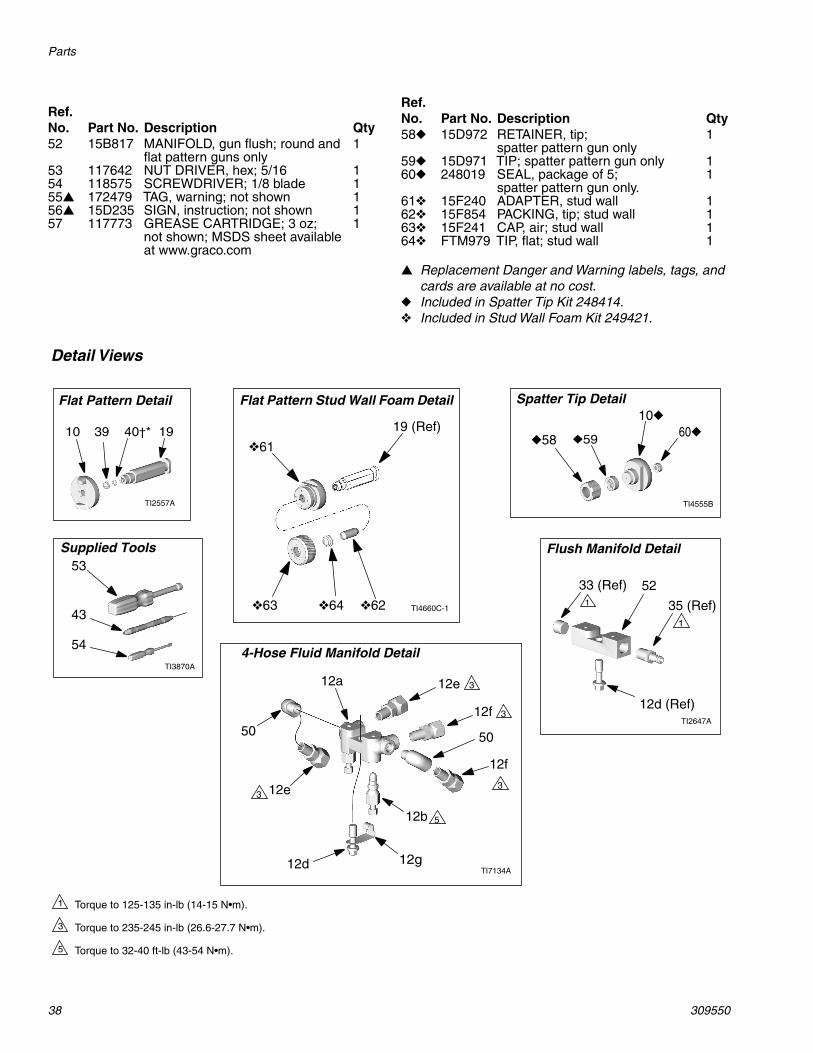
Flat Pattern Detail
1910 39 40†*
Spatter Tip Detail
◆58 ◆59
10◆
60◆
TI4555B
Flat Pattern Stud Wall Foam Detail
TI4660C-1
❖61
❖63 ❖64 ❖62 35 (Ref)
33 (Ref)
12d (Ref)
52
TI2647A
Flush Manifold Detail
1
1
53
43
54
Supplied Tools
TI3870A
Detail Views
TI7134A
4-Hose Fluid Manifold Detail
19 (Ref)
12a
12f
12e
12b
12d
50
3
5
3
12g
Torque to 125-135 in-lb (14-15 N•m).
Torque to 235-245 in-lb (26.6-27.7 N•m).
Torque to 32-40 ft-lb (43-54 N•m).
1
3
5
12f
50
12e 33
Parts
309550 39
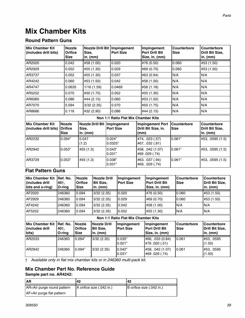
Mix Chamber KitsRound Pattern Guns
Flat Pattern Guns
† Available only in flat mix chamber kits or in 246360 multi-pack kit.
Mix Chamber Part No. Reference GuideSample part no. AR4242:
Mix Chamber Kit(includes drill bits)
NozzleOrificeSize
Nozzle Drill BitSize,in. (mm)
ImpingementPort Size
ImpingementPort Drill BitSize, in. (mm)
CounterboreSize
CounterboreDrill Bit Size,in. (mm)
AR2020 0.042 #58 (1.00) 0.020 #76 (0.50) 0.060 #53 (1.50)
AR2929 0.052 #55 (1.30) 0.029 #69 (0.70) 0.060 #53 (1.50)
AR3737 0.052 #55 (1.30) 0.037 #63 (0.94) N/A N/A
AR4242 0.060 #53 (1.50) 0.042 #58 (1.00) N/A N/A
AR4747 0.0635 1/16 (1.59) 0.0469 #56 (1.18) N/A N/A
AR5252 0.070 #50 (1.75) 0.052 #55 (1.30) N/A N/A
AR6060 0.086 #44 (2.15) 0.060 #53 (1.50) N/A N/A
AR7070 0.094 3/32 (2.35) 0.070 #50 (1.75) N/A N/A
AR8686 0.116 #32 (2.90) 0.086 #44 (2.15) N/A N/A
Non 1:1 Ratio Flat Mix Chamber Kits
Mix Chamber Kit(includes drill bits)
NozzleOrificeSize
Nozzle Drill BitSize,in. (mm)
ImpingementPort Size
Impingement PortDrill Bit Size, in.(mm)
CounterboreSize
CounterboreDrill Bit Size,in. (mm)
AR2232 0.094” 0.047(1.2)
0.024”0.0325”
#74, .023 (.57)#67, .032 (.81)
0.061” #53, .0595 (1.5)
AR2942 0.053” #55 (1.3) 0.043”0.031”
#58, .042 (1.07)#69 .029 (.74)
0.061” #53, .0595 (1.5)
AR3729 0.053” #55 (1.3) 0.038”0.031”
#63, .037 (.94)#69, .029 (.74)
0.061” #53, .0595 (1.5)
Mix Chamber Kit(includes drillbits and o-ring)
Ref. No.40†,O-ring
NozzleOrificeSize
Nozzle DrillBit Size,in. (mm)
ImpingementPort Size
ImpingementPort Drill BitSize, in. (mm)
CounterboreSize
CounterboreDrill Bit Size,in. (mm)
AF2020 246360 0.094 3/32 (2.35) 0.020 #76 (0.50) 0.060 #53 (1.50)
AF2929 246360 0.094 3/32 (2.35) 0.029 #69 (0.70) 0.060 #53 (1.50)
AF4242 246360 0.094 3/32 (2.35) 0.042 #58 (1.00) N/A N/A
AF5252 246360 0.094 3/32 (2.35) 0.052 #55 (1.30) N/A N/A
Non 1:1 Ratio Flat Mix Chamber Kits
Mix Chamber Kit(includes drillbits)
Ref. No.40†,O-ring
NozzleOrificeSize
Nozzle DrillBit Size,in. (mm)
ImpingementPort Size
ImpingementPort Drill BitSize, in. (mm)
CounterboreSize
CounterboreDrill Bit Size,in. (mm)
AR2033 246360 0.094” 3/32 (2.35) 0.035”0.021”
#66, .033 (0.84)#76 .020 (.51)
0.061 #53, .0595(1.50)
AR2942 246360 0.094” 3/32 (2.35) 0.042”0.031”
#58, .042 (1.07)#69 .029 (.74)
0.061 #53, .0595(1.50)
AR 42 42
AR=Air purge round pattern
AF=Air purge flat pattern
A orifice size (.042 in.) B orifice size (.042 in.)

Parts
40 309550
Flat Tip KitsFlat Tip Part No. Reference Guide
Sample part no. FT0848:
Gun Repair KitsRead the chart left to right and top to bottom to find the quantity of each part in the kits.
Check Valve Filter Screen KitsKits include 10 filter screens.
80 mesh filter screen is standard with gun.
246357 40 mesh (.015 in., 375 micron)
246358 60 mesh (.010 in., 238 micron)
246359 80 mesh (.007 in., 175 micron)
Ref. No. 39,Flat Spray Tip
Pattern Size, in. (mm)
FT0424 low flow, 8-10 (203-254)
FT0438 medium flow, 8-10 (203-254)
FT0624 low flow, 12-14 (305-356)
FT0638 medium flow, 12-14 (305-356)
FT0838 medium flow, 16-18 (406-457)
FT0848 high flow, 16-18 (406-457)
FT 08 48
FT=Flat tip x2=patternlength(8x2=16 in.)
Equivalent orificediameter size(.048 in.)
Ref.No.
Bulk O-ringKits, (qty)
246347Side SealCartridgeO-ring Kit
246348SideSeal Kit
246351CheckValveO-ring Kit
246355CompleteO-ring Kit
3 248137 (6) 1
14 248136 (6) 1
16 248135 (6) 1
17 248134 (6) 1
18c 2
18d 248130 (6) 4 4
18e 248128 (6) 2 2 2
21 248132 (6) 1
23 248131 (6) 1
24 246354 (6) 5
26f 248133 (6) 2 2
26g 248129 (6) 2 2
40 246360 (3)
Parts
309550 41
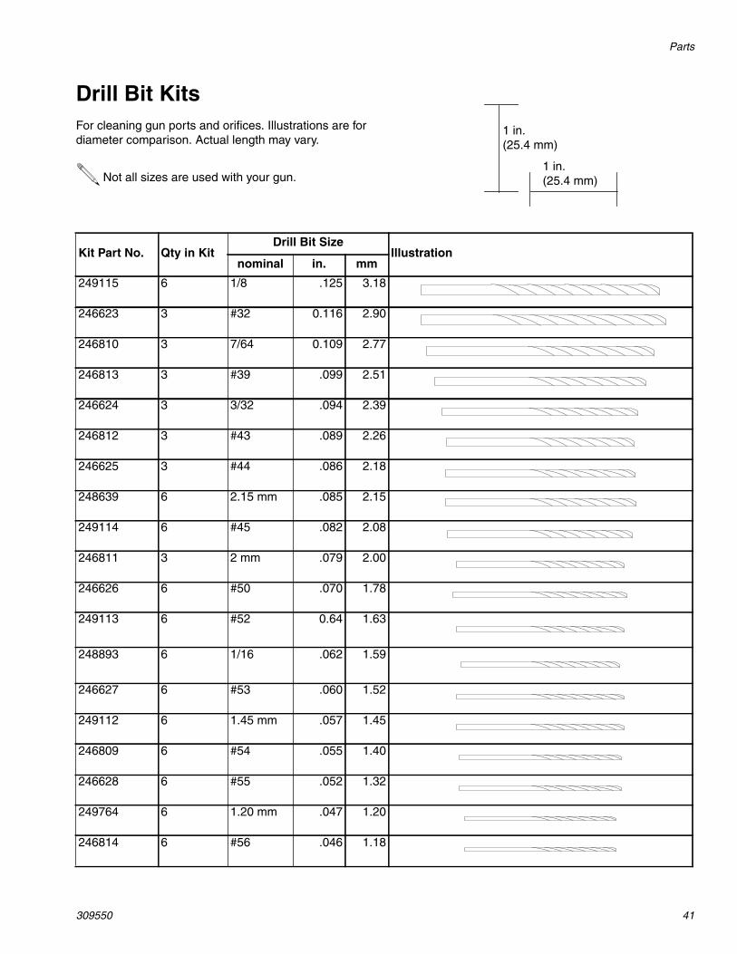
Drill Bit KitsFor cleaning gun ports and orifices. Illustrations are fordiameter comparison. Actual length may vary.
Not all sizes are used with your gun.1 in.(25.4 mm)
1 in.(25.4 mm)
Kit Part No. Qty in KitDrill Bit Size
Illustrationnominal in. mm
249115 6 1/8 .125 3.18
246623 3 #32 0.116 2.90
246810 3 7/64 0.109 2.77
246813 3 #39 .099 2.51
246624 3 3/32 .094 2.39
246812 3 #43 .089 2.26
246625 3 #44 .086 2.18
248639 6 2.15 mm .085 2.15
249114 6 #45 .082 2.08
246811 3 2 mm .079 2.00
246626 6 #50 .070 1.78
249113 6 #52 0.64 1.63
248893 6 1/16 .062 1.59
246627 6 #53 .060 1.52
249112 6 1.45 mm .057 1.45
246809 6 #54 .055 1.40
246628 6 #55 .052 1.32
249764 6 1.20 mm .047 1.20
246814 6 #56 .046 1.18
Parts
42 309550
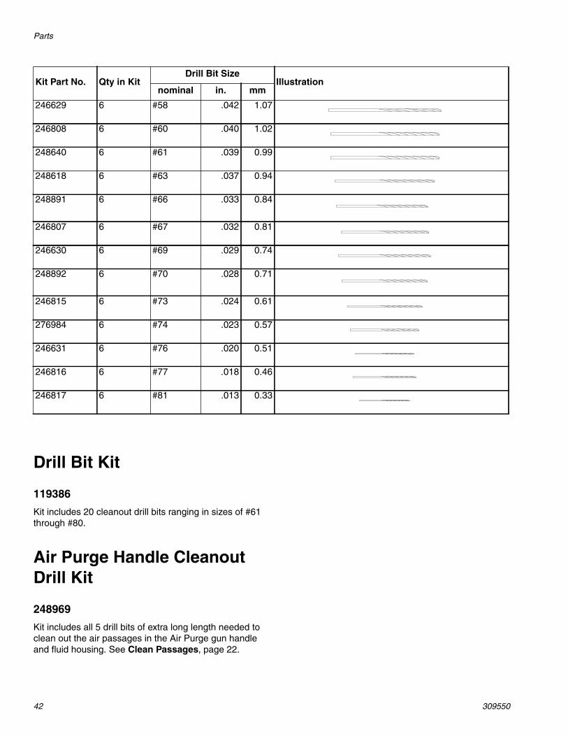
Drill Bit Kit
119386
Kit includes 20 cleanout drill bits ranging in sizes of #61through #80.
Air Purge Handle CleanoutDrill Kit
248969
Kit includes all 5 drill bits of extra long length needed toclean out the air passages in the Air Purge gun handleand fluid housing. See Clean Passages, page 22.
246629 6 #58 .042 1.07
246808 6 #60 .040 1.02
248640 6 #61 .039 0.99
248618 6 #63 .037 0.94
248891 6 #66 .033 0.84
246807 6 #67 .032 0.81
246630 6 #69 .029 0.74
248892 6 #70 .028 0.71
246815 6 #73 .024 0.61
276984 6 #74 .023 0.57
246631 6 #76 .020 0.51
246816 6 #77 .018 0.46
246817 6 #81 .013 0.33
Kit Part No. Qty in KitDrill Bit Size
Illustrationnominal in. mm
Accessories
309550 43
Accessories
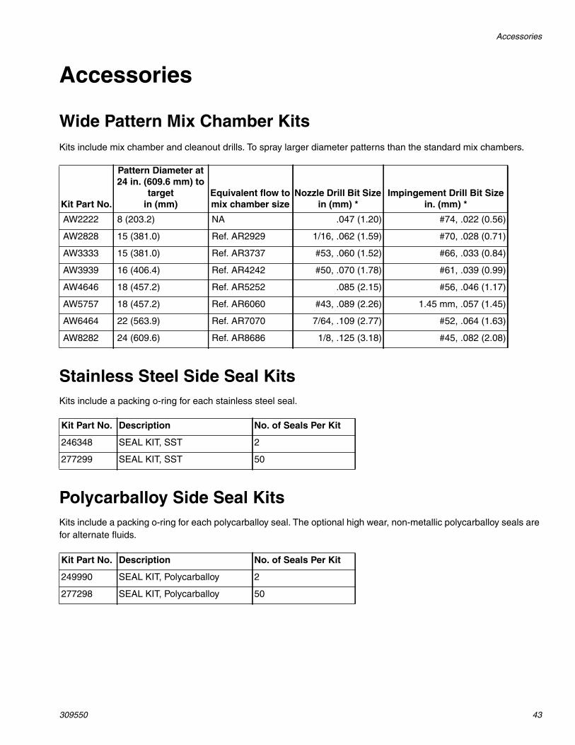
Wide Pattern Mix Chamber KitsKits include mix chamber and cleanout drills. To spray larger diameter patterns than the standard mix chambers.
Stainless Steel Side Seal KitsKits include a packing o-ring for each stainless steel seal.
Polycarballoy Side Seal KitsKits include a packing o-ring for each polycarballoy seal. The optional high wear, non-metallic polycarballoy seals arefor alternate fluids.
Kit Part No.
Pattern Diameter at24 in. (609.6 mm) to
targetin (mm)
Equivalent flow tomix chamber size
Nozzle Drill Bit Sizein (mm) *
Impingement Drill Bit Sizein. (mm) *
AW2222 8 (203.2) NA .047 (1.20) #74, .022 (0.56)
AW2828 15 (381.0) Ref. AR2929 1/16, .062 (1.59) #70, .028 (0.71)
AW3333 15 (381.0) Ref. AR3737 #53, .060 (1.52) #66, .033 (0.84)
AW3939 16 (406.4) Ref. AR4242 #50, .070 (1.78) #61, .039 (0.99)
AW4646 18 (457.2) Ref. AR5252 .085 (2.15) #56, .046 (1.17)
AW5757 18 (457.2) Ref. AR6060 #43, .089 (2.26) 1.45 mm, .057 (1.45)
AW6464 22 (563.9) Ref. AR7070 7/64, .109 (2.77) #52, .064 (1.63)
AW8282 24 (609.6) Ref. AR8686 1/8, .125 (3.18) #45, .082 (2.08)
Kit Part No. Description No. of Seals Per Kit
246348 SEAL KIT, SST 2
277299 SEAL KIT, SST 50
Kit Part No. Description No. of Seals Per Kit
249990 SEAL KIT, Polycarballoy 2
277298 SEAL KIT, Polycarballoy 50
Accessories
44 309550
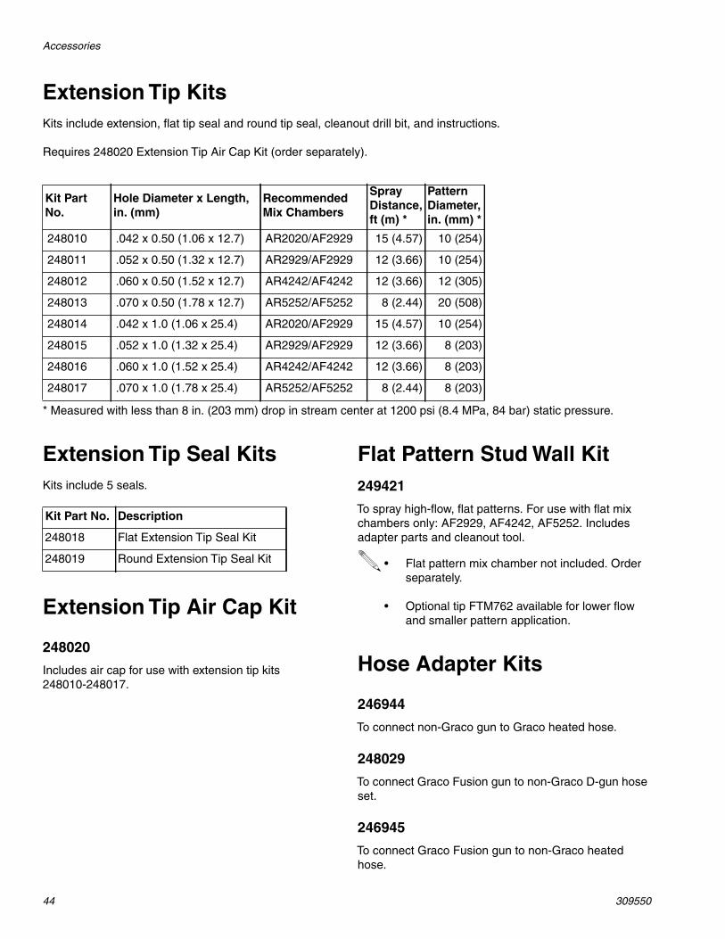
Extension Tip KitsKits include extension, flat tip seal and round tip seal, cleanout drill bit, and instructions.
Requires 248020 Extension Tip Air Cap Kit (order separately).
* Measured with less than 8 in. (203 mm) drop in stream center at 1200 psi (8.4 MPa, 84 bar) static pressure.
Extension Tip Seal KitsKits include 5 seals.
Extension Tip Air Cap Kit
248020
Includes air cap for use with extension tip kits248010-248017.
Flat Pattern Stud Wall Kit249421
To spray high-flow, flat patterns. For use with flat mixchambers only: AF2929, AF4242, AF5252. Includesadapter parts and cleanout tool.
Hose Adapter Kits
246944
To connect non-Graco gun to Graco heated hose.
248029
To connect Graco Fusion gun to non-Graco D-gun hoseset.
246945
To connect Graco Fusion gun to non-Graco heatedhose.
Kit PartNo.
Hole Diameter x Length,in. (mm)
RecommendedMix Chambers
SprayDistance,ft (m) *
PatternDiameter,in. (mm) *
248010 .042 x 0.50 (1.06 x 12.7) AR2020/AF2929 15 (4.57) 10 (254)
248011 .052 x 0.50 (1.32 x 12.7) AR2929/AF2929 12 (3.66) 10 (254)
248012 .060 x 0.50 (1.52 x 12.7) AR4242/AF4242 12 (3.66) 12 (305)
248013 .070 x 0.50 (1.78 x 12.7) AR5252/AF5252 8 (2.44) 20 (508)
248014 .042 x 1.0 (1.06 x 25.4) AR2020/AF2929 15 (4.57) 10 (254)
248015 .052 x 1.0 (1.32 x 25.4) AR2929/AF2929 12 (3.66) 8 (203)
248016 .060 x 1.0 (1.52 x 25.4) AR4242/AF4242 12 (3.66) 8 (203)
248017 .070 x 1.0 (1.78 x 25.4) AR5252/AF5252 8 (2.44) 8 (203)
Kit Part No. Description
248018 Flat Extension Tip Seal Kit
248019 Round Extension Tip Seal Kit • Flat pattern mix chamber not included. Orderseparately.
• Optional tip FTM762 available for lower flowand smaller pattern application.

Accessories
309550 45
Spatter Conversion Kit
248414
To convert Fusion air purge gun to spray, round patternonly, large droplet, low overspray applications. Includesair cap, tip, retainer, seal, and cleanout drill bits.
Pour Nozzle Kit
248528
To convert air purge gun for pour applications. Includesnozzle, seals, tubing, and cleanout drill bits.
Gun Cover
244914 Covers
Keeps gun clean while spraying. Pack of 10.
Lubricant for Gun Rebuild
248279, 4 oz (113 gram) [10]
High adhesion, water resistant, lithium-based lubricant.MSDS sheet available at www.graco.com.
Grease Cartridge for GunShutdown
248280 Cartridge, 3 oz [10]
Specially formulated low viscosity grease flows easilythrough gun passages, to prevent 2 component curingand keep fluid passages clean. See page 16.
Flushing Manifold
15B817 Manifold Block
See ref. no. 52, page 36.
Solvent Flush Canister Kit
248139, 1 qt (0.95 liter) Solvent Cup
Complete with15B817 Flushing Manifold to flush gunwith solvent. Portable for remote flushing. See manual309963.
Solvent Flush Pail Kit
248229 5.0 gal. (19 liter) Pail
Includes flush manifold with individual A and B shutoffvalves, and air regulator. See manual 309963.
Tip Cleanout Tool
15D234
Designed to fit CeramTip internal dome and flat tip slits.
TI4165a
TI4211b
TI4244a
End for AirPurge Tips
End forMechanicalPurge Tips

Accessories
46 309550
Gun Cleaning Kit
15D546
Kit includes 11 tools and brushes to clean the gun.
Circulation Manifold
246362
Attach to gun fluid manifold to enable preheating ofhose. See manual 309818.
Gun GripsApplicator's comfort level with a spray gun is an essen-tial part of the spray foam and polyurea installation pro-cess. The applicator's fatigue level can dramaticallyaffect the pattern and productivity of a project. 3M™Gripping Material Technology is designed to:
• Reduce fatigue
• Provide comfort
• Give thermal protection
Gun Grip Kit
Graco Gun Grips are designed to be used on Fusion®
A, CS, or Probler® P2 Guns.
TI3877a
Kit Part No. Qty in Kit
17G542 10 Pack
17G543 50 Pack
17G544 100 Pack
Technical Data
309550 47
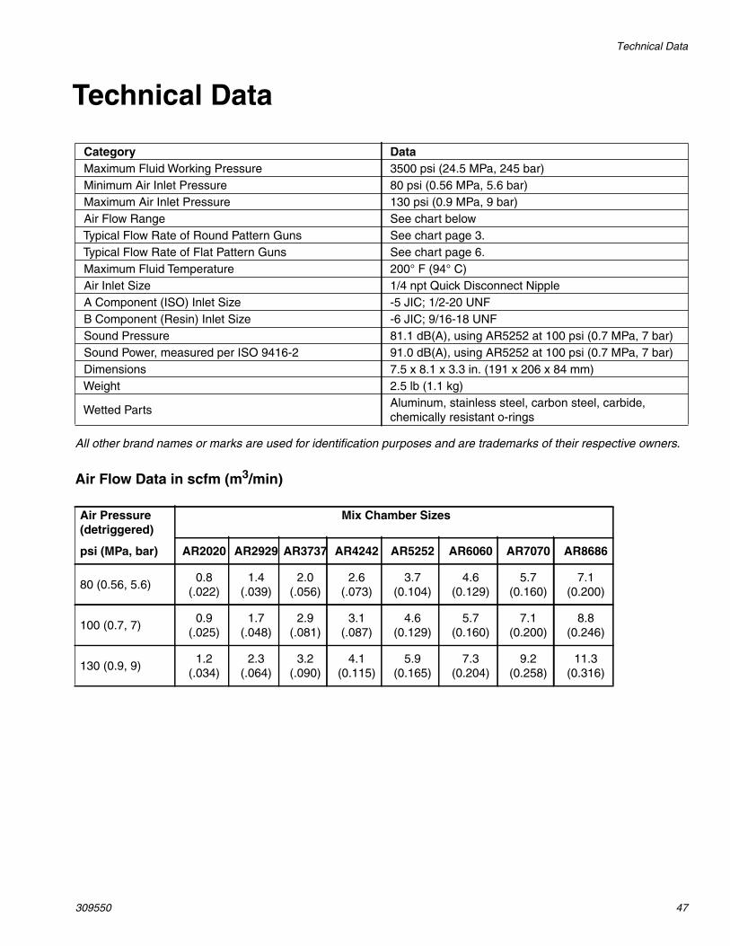
Technical Data
All other brand names or marks are used for identification purposes and are trademarks of their respective owners.
Air Flow Data in scfm (m3/min)
Category DataMaximum Fluid Working Pressure 3500 psi (24.5 MPa, 245 bar)Minimum Air Inlet Pressure 80 psi (0.56 MPa, 5.6 bar)Maximum Air Inlet Pressure 130 psi (0.9 MPa, 9 bar)Air Flow Range See chart belowTypical Flow Rate of Round Pattern Guns See chart page 3.Typical Flow Rate of Flat Pattern Guns See chart page 6.Maximum Fluid Temperature 200° F (94° C)Air Inlet Size 1/4 npt Quick Disconnect NippleA Component (ISO) Inlet Size -5 JIC; 1/2-20 UNFB Component (Resin) Inlet Size -6 JIC; 9/16-18 UNFSound Pressure 81.1 dB(A), using AR5252 at 100 psi (0.7 MPa, 7 bar)Sound Power, measured per ISO 9416-2 91.0 dB(A), using AR5252 at 100 psi (0.7 MPa, 7 bar)Dimensions 7.5 x 8.1 x 3.3 in. (191 x 206 x 84 mm)Weight 2.5 lb (1.1 kg)
Wetted PartsAluminum, stainless steel, carbon steel, carbide,chemically resistant o-rings
Air Pressure(detriggered)
Mix Chamber Sizes
psi (MPa, bar) AR2020 AR2929 AR3737 AR4242 AR5252 AR6060 AR7070 AR8686
80 (0.56, 5.6)0.8
(.022)1.4
(.039)2.0
(.056)2.6
(.073)3.7
(0.104)4.6
(0.129)5.7
(0.160)7.1
(0.200)
100 (0.7, 7)0.9
(.025)1.7
(.048)2.9
(.081)3.1
(.087)4.6
(0.129)5.7
(0.160)7.1
(0.200)8.8
(0.246)
130 (0.9, 9)1.2
(.034)2.3
(.064)3.2
(.090)4.1
(0.115)5.9
(0.165)7.3
(0.204)9.2
(0.258)11.3
(0.316)

All written and visual data contained in this document reflects the latest product information available at the time of publication.Graco reserves the right to make changes at any time without notice.
This manual contains English. MM 309550
Graco Headquarters: MinneapolisInternational Offices: Belgium, China, Japan, Korea
GRACO INC. AND SUBSIDIARIES • P.O. BOX 1441 • MINNEAPOLIS MN 55440-1441 • USACopyright 2002, Graco Inc. All Graco manufacturing locations are registered to ISO 9001.
www.graco.comRevision ZAL, January 2018
Graco Standard WarrantyGraco warrants all equipment referenced in this document which is manufactured by Graco and bearing its name to be free from defects inmaterial and workmanship on the date of sale to the original purchaser for use. With the exception of any special, extended, or limited warrantypublished by Graco, Graco will, for a period of twelve months from the date of sale, repair or replace any part of the equipment determined byGraco to be defective. This warranty applies only when the equipment is installed, operated and maintained in accordance with Graco’s writtenrecommendations.
This warranty does not cover, and Graco shall not be liable for general wear and tear, or any malfunction, damage or wear caused by faultyinstallation, misapplication, abrasion, corrosion, inadequate or improper maintenance, negligence, accident, tampering, or substitution ofnon-Graco component parts. Nor shall Graco be liable for malfunction, damage or wear caused by the incompatibility of Graco equipment withstructures, accessories, equipment or materials not supplied by Graco, or the improper design, manufacture, installation, operation ormaintenance of structures, accessories, equipment or materials not supplied by Graco.
This warranty is conditioned upon the prepaid return of the equipment claimed to be defective to an authorized Graco distributor for verification ofthe claimed defect. If the claimed defect is verified, Graco will repair or replace free of charge any defective parts. The equipment will be returnedto the original purchaser transportation prepaid. If inspection of the equipment does not disclose any defect in material or workmanship, repairswill be made at a reasonable charge, which charges may include the costs of parts, labor, and transportation.
THIS WARRANTY IS EXCLUSIVE, AND IS IN LIEU OF ANY OTHER WARRANTIES, EXPRESS OR IMPLIED, INCLUDING BUT NOTLIMITED TO WARRANTY OF MERCHANTABILITY OR WARRANTY OF FITNESS FOR A PARTICULAR PURPOSE.
Graco’s sole obligation and buyer’s sole remedy for any breach of warranty shall be as set forth above. The buyer agrees that no other remedy(including, but not limited to, incidental or consequential damages for lost profits, lost sales, injury to person or property, or any other incidental orconsequential loss) shall be available. Any action for breach of warranty must be brought within two (2) years of the date of sale.
GRACO MAKES NO WARRANTY, AND DISCLAIMS ALL IMPLIED WARRANTIES OF MERCHANTABILITY AND FITNESS FOR APARTICULAR PURPOSE, IN CONNECTION WITH ACCESSORIES, EQUIPMENT, MATERIALS OR COMPONENTS SOLD BUT NOTMANUFACTURED BY GRACO. These items sold, but not manufactured by Graco (such as electric motors, switches, hose, etc.), are subject tothe warranty, if any, of their manufacturer. Graco will provide purchaser with reasonable assistance in making any claim for breach of thesewarranties.
In no event will Graco be liable for indirect, incidental, special or consequential damages resulting from Graco supplying equipment hereunder, orthe furnishing, performance, or use of any products or other goods sold hereto, whether due to a breach of contract, breach of warranty, thenegligence of Graco, or otherwise.
FOR GRACO CANADA CUSTOMERSThe Parties acknowledge that they have required that the present document, as well as all documents, notices and legal proceedings entered into,given or instituted pursuant hereto or relating directly or indirectly hereto, be drawn up in English. Les parties reconnaissent avoir convenu que larédaction du présente document sera en Anglais, ainsi que tous documents, avis et procédures judiciaires exécutés, donnés ou intentés, à la suitede ou en rapport, directement ou indirectement, avec les procédures concernées.
Graco InformationFor the latest information about Graco products, visit www.graco.com.For patent information, see www.graco.com/patents.
TO PLACE AN ORDER, contact your Graco distributor or call to identify the nearest dis-tributor.Phone: 612-623-6921 or Toll Free: 1-800-328-0211 Fax: 612-378-3505