EN PL C370-2SI - HYDMECH · 2016-06-23 · 11 Introduction and technical specifications 1-3 SPINDLE...
143
PL USE AND MAINTENANCE MANUAL YEAR OF MANUFACTURE: ______________ EN C370- 2SI
Transcript of EN PL C370-2SI - HYDMECH · 2016-06-23 · 11 Introduction and technical specifications 1-3 SPINDLE...

PL
USE AND MAINTENANCE MANUAL
YEAR OF MANUFACTURE: ______________
EN C370- 2SI


EN”CE” CONFORMITY DECLARATION
(according to EEC MACHINES DIRECTIVE 2006/42/CE annex II A)
The manufacturer:
MEP S.p.A.Via Enzo Magnani, 1
61045 Pergola (PU) ITALIATel. 072173721-Fax 0721734533
Hereby declares that the circular sawing machine:
Machine model:
Serial number:
Year of manufacture:
C370- 2SI
Machine Type: SAWING MACHINE
is in specification with the following directives:
• DIRECTIVE EEC MACHINES DIRECTIVE 2006/42/CE• DIRECTIVE 2006/95/CE ”LVD”• DIRECTIVE 2004/108/CE ”EMC”• D. Lgs. 17/2010
Responsible of a Technical File(Walter Di Giovanni) c/o MEP SPA
Via Enzo Magnani, 161045 - Pergola - PU - ITALY
Pergola, lì
Managing Director(William Giacometti)


5
Introduction and technical specifications 1-1. . . . . . . . . . . . .
Foreword 1-1. . . . . . . . . . . . . . . . . . . . . . . . . . . . . . . . . . . . . .
Machine presentation 1-1. . . . . . . . . . . . . . . . . . . . . . . . . . . . .
Machine specification 1-1. . . . . . . . . . . . . . . . . . . . . . . . . . . .
Dimensions 1-4. . . . . . . . . . . . . . . . . . . . . . . . . . . . . . . . . . . .
Functional parts 2-1. . . . . . . . . . . . . . . . . . . . . . . . . . . . . . . . .
C370-2SI model 2-1. . . . . . . . . . . . . . . . . . . . . . . . . . . . . . . .
Cutting head 2-1. . . . . . . . . . . . . . . . . . . . . . . . . . . . . . . . . . . .
Vice 2-2. . . . . . . . . . . . . . . . . . . . . . . . . . . . . . . . . . . . . . . . . .
Oil pneumatic unit 2-2. . . . . . . . . . . . . . . . . . . . . . . . . . . . . . .
Electro-pneumatic unit 2-3. . . . . . . . . . . . . . . . . . . . . . . . . . .
Control Panel 2-3. . . . . . . . . . . . . . . . . . . . . . . . . . . . . . . . . . .
Turntable 2-4. . . . . . . . . . . . . . . . . . . . . . . . . . . . . . . . . . . . . .
Head lift unit 2-4. . . . . . . . . . . . . . . . . . . . . . . . . . . . . . . . . . .
Safety and accident prevention 3-1. . . . . . . . . . . . . . . . . . . . .
Use of the machine 3-1. . . . . . . . . . . . . . . . . . . . . . . . . . . . . .
General recommendations 3-2. . . . . . . . . . . . . . . . . . . . . . . . .
Recommendations to the operator 3-3. . . . . . . . . . . . . . . . . . .
Machine safety devices 3-5. . . . . . . . . . . . . . . . . . . . . . . . . . .
Reference standards 3-5. . . . . . . . . . . . . . . . . . . . . . . . . . . . . .
Protection against accidental contact with the blade 3-5. . . . .
Electrical equipment 3-6. . . . . . . . . . . . . . . . . . . . . . . . . . . . .
Emergency devices 3-6. . . . . . . . . . . . . . . . . . . . . . . . . . . . . .
Noise level of the machine 3-7. . . . . . . . . . . . . . . . . . . . . . . . .
Noise level measurement 3-7. . . . . . . . . . . . . . . . . . . . . . . . . .
Noise level values 3-8. . . . . . . . . . . . . . . . . . . . . . . . . . . . . . .
Vibration emission 3-8. . . . . . . . . . . . . . . . . . . . . . . . . . . . . . .
Electromagnetic compatibility 3-8. . . . . . . . . . . . . . . . . . . . . .
Machine installation 4-1. . . . . . . . . . . . . . . . . . . . . . . . . . . . . .
Packaging and storage 4-1. . . . . . . . . . . . . . . . . . . . . . . . . . . .
Anchoring the machine 4-4. . . . . . . . . . . . . . . . . . . . . . . . . . .
Minimum requirements 4-4. . . . . . . . . . . . . . . . . . . . . . . . . . .
Check list 4-5. . . . . . . . . . . . . . . . . . . . . . . . . . . . . . . . . . . . . .
Connection to the compressed air 4-6. . . . . . . . . . . . . . . . . . .
Connection to the power supply 4-7. . . . . . . . . . . . . . . . . . . .
Description of machine operation 5-1. . . . . . . . . . . . . . . . . . .
Description of the control panel 5-1. . . . . . . . . . . . . . . . . . . .

6
Basic instructions for carrying out a cutting operation cycle 5-4
Cutting head movement 5-4. . . . . . . . . . . . . . . . . . . . . . . . . . .
Clamping the work piece in the vice 5-4. . . . . . . . . . . . . . . . .
Width of cut 5-5. . . . . . . . . . . . . . . . . . . . . . . . . . . . . . . . . . . .
Transverse position of the vice 5-5. . . . . . . . . . . . . . . . . . . . .
Preliminary check list for cutting operation 5-6. . . . . . . . . . .
Semi- automatic operating cycle 5-7. . . . . . . . . . . . . . . . . . . .
UP and DOWN function 5-8. . . . . . . . . . . . . . . . . . . . . . . . . .
Angled cuts 5-9. . . . . . . . . . . . . . . . . . . . . . . . . . . . . . . . . . . .
Angled cuts 45 and 60 to the left 5-9. . . . . . . . . . . . . . . . .
Angled cuts 45 to the right 5-10. . . . . . . . . . . . . . . . . . . . . . .
Diagrams, exploded views and replacement parts 6-1. . . . . . .
Standardised Wiring Diagrams (CENELEC Standard) 6-2. . .
List of components 6-32. . . . . . . . . . . . . . . . . . . . . . . . . . . . . . .
Pneumatic diagram 6-34. . . . . . . . . . . . . . . . . . . . . . . . . . . . . .
List of components 6-37. . . . . . . . . . . . . . . . . . . . . . . . . . . . . . .
Exploded views 6-40. . . . . . . . . . . . . . . . . . . . . . . . . . . . . . . . .
Head unit 6-40. . . . . . . . . . . . . . . . . . . . . . . . . . . . . . . . . . . . . .
Control panel 6-43. . . . . . . . . . . . . . . . . . . . . . . . . . . . . . . . . . .
Motor assembly 6-45. . . . . . . . . . . . . . . . . . . . . . . . . . . . . . . . .
Vice 6-47. . . . . . . . . . . . . . . . . . . . . . . . . . . . . . . . . . . . . . . . . .
Turntable 6-49. . . . . . . . . . . . . . . . . . . . . . . . . . . . . . . . . . . . . .
Fix plattform assembly 6-51. . . . . . . . . . . . . . . . . . . . . . . . . . .
Blade guard unit 6-53. . . . . . . . . . . . . . . . . . . . . . . . . . . . . . . . .
Base assembly 6-55. . . . . . . . . . . . . . . . . . . . . . . . . . . . . . . . . .
Cylinder unit 6-57. . . . . . . . . . . . . . . . . . . . . . . . . . . . . . . . . . .
Adjustments 7-1. . . . . . . . . . . . . . . . . . . . . . . . . . . . . . . . . . . .
Displaying and editing the set- up parameters 7-1. . . . . . . . . .
Set language parameter 7-2. . . . . . . . . . . . . . . . . . . . . . . . . . .
Set parameter for machine type 7-2. . . . . . . . . . . . . . . . . . . . .
Semiautomatic-Dynamic and Manual operation setting 7-2. .
Pedal control setting (optional) 7-3. . . . . . . . . . . . . . . . . . . . .
Inverter presence settings 7-3. . . . . . . . . . . . . . . . . . . . . . . . . .
Blade speed proximity settings 7-3. . . . . . . . . . . . . . . . . . . . .
Minimal lubrication system settings 7-3. . . . . . . . . . . . . . . . .
FCTI / FCTA digital output enabling setting 7-3. . . . . . . . . . .
Disc stop setting 7-4. . . . . . . . . . . . . . . . . . . . . . . . . . . . . . . . .

7
Cutting vice opening setting 7-4. . . . . . . . . . . . . . . . . . . . . . .
Cutting vice opening/closing time setting 7-4. . . . . . . . . . . . .
Machine maximum power input setting 7-4. . . . . . . . . . . . . .
Measurement unit setting 7-4. . . . . . . . . . . . . . . . . . . . . . . . . .
Setting minimum blade tensioning 7-5. . . . . . . . . . . . . . . . . .
Display backlighting time setting 7-5. . . . . . . . . . . . . . . . . . .
Cutting head stroke 7-5. . . . . . . . . . . . . . . . . . . . . . . . . . . . . .
Software version and total use time of the machine 7-7. . . . .
Adjusting the display brightness 7-7. . . . . . . . . . . . . . . . . . . .
Air treatment unit 7-8. . . . . . . . . . . . . . . . . . . . . . . . . . . . . . . .
Cutting head operating pressure 7-8. . . . . . . . . . . . . . . . . . . .
Cutting head actuator cylinder (CPT) 7-9. . . . . . . . . . . . . . . .
Replenishing the head cylinder 7-9. . . . . . . . . . . . . . . . . . . . .
Vice 7-10. . . . . . . . . . . . . . . . . . . . . . . . . . . . . . . . . . . . . . . . . .
Adjusting the vice play 7-10. . . . . . . . . . . . . . . . . . . . . . . . . . .
Rag prevention device 7-11. . . . . . . . . . . . . . . . . . . . . . . . . . . .
Adjusting operating head travel 7-12. . . . . . . . . . . . . . . . . . . . .
Disc 7-12. . . . . . . . . . . . . . . . . . . . . . . . . . . . . . . . . . . . . . . . . .
Adjusting the turntable stops 7-12. . . . . . . . . . . . . . . . . . . . . . .
Changing the blade 7-14. . . . . . . . . . . . . . . . . . . . . . . . . . . . . .
Adjusting the position of the blade- cleaning brush 7-16. . . . .
Maintenance and choice of consumables 8-1. . . . . . . . . . . . . .
The role of the operator 8-1. . . . . . . . . . . . . . . . . . . . . . . . . . .
Maintenance requirements 8-2. . . . . . . . . . . . . . . . . . . . . . . . .
General maintenance 8-2. . . . . . . . . . . . . . . . . . . . . . . . . . . . .
Daily 8-2. . . . . . . . . . . . . . . . . . . . . . . . . . . . . . . . . . . . . . . . . .
Weekly 8-2. . . . . . . . . . . . . . . . . . . . . . . . . . . . . . . . . . . . . . . .
Monthly 8-2. . . . . . . . . . . . . . . . . . . . . . . . . . . . . . . . . . . . . . .
Consumable materials 8-3. . . . . . . . . . . . . . . . . . . . . . . . . . . .
Oils for pneumatic and hydraulic circuit 8-3. . . . . . . . . . . . . .
Oils for lubrication/coolant liquid 8-3. . . . . . . . . . . . . . . . . . .
Oils for spray mist system (optional) 8-3. . . . . . . . . . . . . . . . .
Oils for transmission box 8-3. . . . . . . . . . . . . . . . . . . . . . . . . .
Cutting speed and choice of tools 9-1. . . . . . . . . . . . . . . . . . .
Cutting speed 9-1. . . . . . . . . . . . . . . . . . . . . . . . . . . . . . . . . . .
C370-2SI, standard machine 9-1. . . . . . . . . . . . . . . . . . . . . . .
Choice of blade 9-1. . . . . . . . . . . . . . . . . . . . . . . . . . . . . . . . .

8
Tooth pitch 9-1. . . . . . . . . . . . . . . . . . . . . . . . . . . . . . . . . . . . .
Types of swarf: 9-2. . . . . . . . . . . . . . . . . . . . . . . . . . . . . . . . . .
Cutting and feeding speed 9-3. . . . . . . . . . . . . . . . . . . . . . . . .
Lubricant/coolant 9-3. . . . . . . . . . . . . . . . . . . . . . . . . . . . . . . .
Blade structure 9-3. . . . . . . . . . . . . . . . . . . . . . . . . . . . . . . . . .
Types of blades 9-4. . . . . . . . . . . . . . . . . . . . . . . . . . . . . . . . .
Tooth shape 9-4. . . . . . . . . . . . . . . . . . . . . . . . . . . . . . . . . . . .
Blade selection table with respect to cutting speed and downstroke speed 9-6
Classification of steels 9-7. . . . . . . . . . . . . . . . . . . . . . . . . . . .
Classification of steels 9-8. . . . . . . . . . . . . . . . . . . . . . . . . . . .
Troubleshooting 10-1. . . . . . . . . . . . . . . . . . . . . . . . . . . . . . . . .
Troubleshooting blade and cutting problems 10-1. . . . . . . . . . .
Troubleshooting 10-3. . . . . . . . . . . . . . . . . . . . . . . . . . . . . . . . .
Diagnostics system 10-4. . . . . . . . . . . . . . . . . . . . . . . . . . . . . . .
Machine alarms and emergencies 10-6. . . . . . . . . . . . . . . . . . .
Accessory Installation 11-1. . . . . . . . . . . . . . . . . . . . . . . . . . . .
Supplementary pneumatic vice 11-1. . . . . . . . . . . . . . . . . . . . .
Circular blade 11-1. . . . . . . . . . . . . . . . . . . . . . . . . . . . . . . . . . .
Roller table 11-2. . . . . . . . . . . . . . . . . . . . . . . . . . . . . . . . . . . . .
Adattatore pianale a rulli lato scarico 11-3. . . . . . . . . . . . . . . .
Feed side roller table support 11-4. . . . . . . . . . . . . . . . . . . . . . .
Bar support 11-4. . . . . . . . . . . . . . . . . . . . . . . . . . . . . . . . . . . . .

1- 1
Introduction andtechnicalspecifications
ForewordWe have decades of experience in the construction of the best metal- cuttingmachines. Our experience, our knowledge of our customers and constanttechnological development of design and production equipment allow us to offera specific solution for every type of cutting need. This work tool has beendesigned as a simple and reliable answer to the wide range of cutting needs of themodern workshop. The C370- 2SI is an electro- pneumatic, semiautomaticvertical sawing machine, which can execute left angled cuts at 60 degrees andright angled cuts at 45 degrees. These features, together with optimal cuttingcapabilities, make the C370- 2SI a highly versatile machine. Congratulations forhaving chosen this product which, by following the instructions contained in thisuser and maintenance handbook, will guarantee you years of dependable service.
This band saw has been exclusively designed to cut metals.
Machine presentationThe machine can operate in SEMI- AUTOMATIC mode: after setting the headcutting stroke on the control panel and the head downstroke speed, the operatorpositions the vice 2÷3 mm from the workpiece and presses the start button (oroptional foot pedal if fitted) on the control panel to start up the band saw. Thevice then clamps the material, the head lowers, cuts the piece and returns to itsstart position and the vice opens again.
1. The cutter vice clo-ses
2. The head lowers untilthe cut is made (FCTA)
3. The head returns tostart position (FCTI)
4. The cutter vice opens
Machine specificationThe anodised aluminium name plate is riveted on the side of the machine; thesame data are reproduced on the declaration of conformity included with this useand maintenance manu-
Warning
1

MEP S.p.A.
1- 2 10Use and maintenance manual C370- 2SI
al.
When communicating with the Technical Service department, the model, serialnumber and year of manufacture of the machine must be quoted.
CUTTING SPEEDSSpeeds 1/2/3/4 (standard speed) rpm 15 ÷ 150
BLADEExternal disc diameter mm 370
Internal hole diameter mm 32
Blade thickness mm 3
RATED ELECTRICAL POWEROptional three phase head spindle motor KW 5,5
Electric coolant pump motor KW 0,1
Max installed power KW 5,6
WORKING PRESSUREMax. working pressure for opening/closing vice Bar 6
Air consumption for a complete cycle Nl/min 7,35
The ”air consumption for vice” value refers to standard conditions (temperature0° and pressure 1.013 bar, i.e. density 1.3 x 10- 3 Kg/l) where 1 Kg/min. = 772Nl/min.
LUBRICANT/COOLANT FLUID AND OILLubricant/coolant fluid (oil concentration 5- 6%) capacità Lt. 80
Oil for transmission box capacità Lt. 9
VICEVice max. opening mm 190
SPINDLE MOTOR (STANDARD)No.of poles Current (Volts) Absorption
(Amps)Power (Kw) rpm
4 230/400 14,5/8 2,6 1.440
8 230/400 10/5,7 1,8 715
Stator wound with enamelled copper wire, class H 200° C.
N.B.
N.B.

1- 311 Introduction and technical specifications
SPINDLE MOTOR (STANDARD)No.of poles rpmPower (Kw)Absorption
(Amps)Current (Volts)
Class F insulation (limit temperature TL 155° C).IP 54 protection rating (total against contact with live parts, water sprayed from all directions, with shaft oilseal).Conforming to CEI norms, publication: IEC 34 of 01/07/1985.
Example of class F insulation: in air- cooled machines at an ambient tempera-ture of 40° C (according to CEI 2- 3 and IEC 85), the allowable overtempera-ture is 100° C (where 100° C represents the allowable ΔT).
SPINDLE MOTOR (OPTIONAL)No.of poles Current (Volts) Absorption
(Amps)Power (Kw) rpm
4 230/400 9,8/4,6 5,5 1440
Stator wound with enamelled copper wire, class H 200° C.Class F insulation (limit temperature TL 155° C).IP 54 protection rating (total against contact with live parts, water sprayed from all directions, with shaft oilseal).Conforming to CEI norms, publication: IEC 34 of 01/07/1985.
ELECTROPUMP MOTORVoltage (Volts) Absorption (Amps) Power (Kw) rpm
230 0,53 0,1 2800
400 0,34 0,1 2800Protection rating IP 55.Conforming to CEI norms, publication: IEC 34 of 01/07/1985.
CUTTING CAPACITY for SOLID sections
Section
0° 120 100 180 x 100
45° ' 70 70 70 x 100
45° a 70 70 70 x 100
60° a 50 50 50 x 100
CUTTING CAPABILITY FOR SECTIONS
Section
0° 120 110 180 x 100
45° ' 115 100 120 x 100
45° a 115 100 120 x 100
60° a 115 90 90 x 100
N.B.

MEP S.p.A.
1- 4 12Use and maintenance manual C370- 2SI
PACKED WEIGHT
Wooden cage and pallet Kg 70
Wooden pallet Kg 20
14501280
2000
Dimensions
MACHINE INSTALLED
Work table height mm 950
Weight Kg 640

2- 1
Functional parts
C370- 2SI model
In order for the user to move towards a full understanding of how the machineworks, which is described in detail in the chapter 5, this chapter deals with themain units and their locations.
CUTTING HEADCONTROL PANEL
BLADE GUARD UNIT
FIX PLATTFORM
VICE
TURNTABLE
BASE
Coolant guide
Cutting head
The cutting head is the unit that cuts the material. It consists of a cast iron headon which the following are mounted: the band saw, the blade guide components,the blade tensioner components, the transmission box and the spindle motor. The
2

MEP S.p.A.
2- 2 14Use and maintenance manual C370- 2SI
operating head runs on linear guides with ball- recirculating pre- charged slidesand makes a vertical stroke from the up position to the down one; this stroke canbe programmed through the control board.
ViceThe vice is the unit that clamps the workpiece in place during cutting; it consistsof a vice support, commonly known as a lead nut, fixed to the work table, and alead screw with a slideway on which the mobile jaw is mounted. The vice iscontrolled by the vice opening and closing button or by the start button. The viceapproaching movement is manual and the closing is operated by the cylinder(pneumatic).
Oil pneumatic unitThis unit drives and regulates the upward and downward movement of the cuttinghead and consists of a hydro- pneumatic cylinder and recovery electro- valves.The head descent regulator on the control panel can be used to regulate thequantity of oil that flows into the cylinder and naturally the downward movement

2- 315 Functional parts
speed of the cutting head. To facilitate the upward movement of the head, theC370- 2SI has a spring located in the cutting head.
Electro- pneumatic unitThe panel shown in the diagram below is the electro- pneumatic unit. It consistsof an air treatment unit and an electro- valve; the unit serves to filter the airentering the circuit.
Control PanelThe control panel has a protection rating of IP 54 and contains the electricalequipment. Access is gained by removing a few screws, while the operator’s safetyis guaranteed by a key- operated safety switch, designed to prevent any intention-al interference with the unit. In fact, removing the control panel from its mount-ing simultaneously extracts the key from the switch, thus cutting- off the electrici-ty supply to the machine.
Control panel
Main switch
Panel fastened by screws

MEP S.p.A.
2- 4 16Use and maintenance manual C370- 2SI
TurntableA cast iron casting forms the fulcrum for the cutting head, and the support for thework table and the control panel. Releasing the locking lever on the slidewayallows the cutting head to be rotated to the right and to the left.
Head lift unitThis device has a preloaded spring that allows easy up and down movement of thehead.

3- 1
Safety and accidentprevention
The C370- 2SI has been designed and produced in accordance with Europeanstandards. For the correct use of the machine we recommend that the instruc-tions contained in this chapter are carefully followed.
Use of the machineThe C370- 2SI circular saw is designed to cut exclusively ferrous and non- fer-rous profiles and solid metal sections. Other types of material and machining arenot compatible with the specific characteristics of the saw. The employer isresponsible for instructing the personnel who, in turn, are obliged to inform theoperator of any accident risks, safety devices, noise emission and accidentprevention regulations provided for by international standards and national lawsregarding the use of the machine. The operator must be perfectly aware of theposition and function of all the machine’s controls.The instructions, warnings andaccident prevention standards in this manual must be respected without questionby all those concerned.The following definitions are those provided for by EECMACHINES DIRECTIVE 2006/42/CE :H “Danger zone”: any zone in and/or around a machine in which the presence of a
person constitutes a risk for the safety and health of that person.H “Person exposed”: any person finding himself either completely or partly in a dan-
ger zone.H “Operator”: the person or persons given the responsibility of installing, operating,
adjusting, maintaining, cleaning, repairing or transporting the machine.
The manufacturer declines any responsibility whatsoever, either civil or crimi-nal, should there be unauthorised interference or replacement of one or moreparts or assemblies on the machine, or if accessories, tools and consumablematerials are used that are different from those recommended by the manu-facturer itself or if the machine is employed in a plant system and its properfunction is thereby altered.
Attention
3

MEP S.p.A.
3- 2 18Use and maintenance manual C370- 2SI
General recommendations
LIGHTINGInsufficient lighting for the types of operation envisaged could constitute a safetyhazard for the persons concerned. For this reason, the machine user must providelighting in the working area sufficient to eliminate all shadowy areas while alsoavoiding any blinding light concentrations. (Reference standard ISO 8995- 89“Lighting in work environments”).
CONNECTIONSCheck that the power supply cables and pneumatic feed systems comply with themaximum machine absorption values listed in the “Machine Specification” tables;replace if necessary.
EARTHING
The installation of the earthing system must comply with the requirements set outin EN STANDARD 60204- 1:2010.
OPERATOR POSITIONThe position of the operator controlling machine operations must be as shown inthe diagram below.

3- 319 Safety and accident prevention
Recommendations to the operator
Always wear proper goggles or protective glasses.
Do not use the machine without the guards in position. Replace the poly-carbonate windows , if subject to corrosion.
Do not allow hands or arms to encroach on the cutting zone while themachine is in operation.
Do not wear oversize clothing with long sleeves, oversize gloves,bracelets, necklaces or any other object that may become entangled inthe machine during working; long hair must be tied back and bunched.
Always disconnect the power supply to the machine before carrying outany maintenance work whatsoever, including in the case of abnormal op-eration of the machine.
Before starting cutting operations, support the material at both ends ofthe machine using the support arm - standard, or OPTIONAL acces-sories such as the feed and discharge roller tables shown in the diagrambelow.
mm. 1500 mm. 1500
DISCHARGE ROLLER TABLEFEED ROLLER TABLE
Any maintenance work on the hydraulic or pneumatic systems must becarried out only after the pressure in the system has been released.
The operator MUST NOT perform any risky operations or those notrequired for the machining in course (e.g. remove swarf or metal shavingsform the machine while cutting).

MEP S.p.A.
3- 4 20Use and maintenance manual C370- 2SI
Remove equipment, tools or any other objects from the cutting zone; al-ways keep the working area as clean as possible.
Do not use the machine for cutting pieces which exceed the cutting ca-pacity described in the technical specifications or are less than 5 mm
Before starting any cutting operations, ensure that the workpiece is se-curely held in the vice and the machine has been set correctly. A numberof examples of how to clamp the different profiles correctly in our ma-chines are shown below.
Never move the machine while it is cutting.
Do not use blades of different sizes to those recommended in the ma-chine’s specifications.
When cutting very short pieces, make sure that they are not dragged be-hind the support shoulder, where they could jam in the blade.
When using the pneumatic vice (version MA) check that the jaws actuallymove right up to and effectively block the piece, as the maximum travelin only 6 mm, and check that the clamping pressure is correct.
When working on the bandsaw, only wear gloves when handling materialsand tool change or adjustment operations. Only carry out one operationat a time and do not hold more than one item or operate more than onedevice simultaneously. Keep hands as clean as possible.
Warning: if the blade jams in the cut, press the emergency stop pushbut-ton immediately. If this does not free the blade, slowly release the vice,remove the piece and check that the blade or its teeth for damage, ifneed be replace the blade.
Before carrying out any repair works on the machine, consult the Techni-cal Service; this can also be done through an agency in the country inwhich the machine is being used.

3- 521 Safety and accident prevention
Machine safety devicesThis use and maintenance manual is not intended as purely a guide for the use ofthe machine in a strictly productive environment, it is instead an instrumentproviding information on how to use the machine correctly and safely. Thefollowing standards are those specified by the EEC Committee in the directivesregarding safety of machinery, health and safety at work, personal protection andsafeguarding of the environment. These standards have been applied to theC370- 2SI band saw.
Reference standards
MACHINE SAFETYH EEC MACHINES DIRECTIVE 2006/42/CE ;
H EEC directive no. 2004/108/CE “EMC - Electromagnetic Compatibility”;
H EEC Directive No. 2006/95/CE known as “Low voltage directive”.
H EN 13898:2003+A1:2009 Machine tools - Safety - Sawing machines for coldmetal
HEALTH AND SAFETY AT WORKH EEC Directive No. 80/1107; 83/477;86/188;88/188; 88/642 for the protection of
workers against risks caused by exposure to physical, chemical and biologicalagents during working;
H EEC Directive No. 89/391 and Special EEC Directives No. 89/654 and No. 89/655for improvements in health and safety at work;
H EEC Directive No. 90/394 for the protection of workers against risks deriving fromexposure at work to carcinogenic substances;
H EEC Directive No. 77/576 and No. 79/640 on safety signs at work.
PERSONAL PROTECTIONH EEC Directive No. 89/656 and No. 89/686 on the use of personal protection de-
vices.
ENVIRONMENTAL PROTECTIONH EEC Directive No. 75/442 on waste disposal;
H EEC Directive No. 75/439 on the disposal of used oil.
H Directive 2002/95/EC on the restriction of the use of certain hazardous substancesin electrical and electronic equipment (RoHS).
Protection against accidental contact with the blade
1. Metal disc guard fixed to the upright section that guides the movement of thehead. The height of this guard can be regulated so that the only part of theblade exposed is that used for the actual cutting in accordance with DPR547/55 art. 108;
2. steel sheet guard of adjustable height located on the part of the blade guardbetween the operator and disc and used as splash guard;
3. vertical pneumatic vice and vice with rag prevention device and double clamp-ing for improved hold on workpiece (optional double pneumatic vice);
4. the cutting vice is operated pneumatically via a button on the control paneland has a maximum travel of 6 mm. The jaw that clamps the material must bemoved to within a distance of 2÷3 mm of the workpiece;
5. blade approaching device to the piece to be cut: the operator can approach,

MEP S.p.A.
3- 6 22Use and maintenance manual C370- 2SI
through the head lifting and lowering buttons, the blade to the piece to be cut,to clear only the stroke sufficient and necessary for this operation.
4
2
1
35
Electrical equipment
In accordance with Italian standard CEI EN 60204- 1:2010, derived fromEuropean Standard EN 60204- 1:2010:
H access to electrical board limited by screws and automatic electro- thermal mainswitch with Minimum Voltage Coil;
H 24 Vac Control voltage for actuators, in accordance with chapter 6 of EuropeanStandard ”Control and indication circuits” paragraph 2 ”Control Circuits” sub- sec-tion 1 ”Preferential voltage values for control circuits”;
H plant protected against short circuits by quick blowing fuses and earthing of allwork and accidental contact parts;
H protection from accidental start- up by a minimum voltage relay in the case of pow-er failure.
Emergency devices
In accordance with Standard EN 60204- 1:2010:
H Chapter 5 Section 6 Sub- section 1 ”Emergency stop device”: «the emergencystop device immediately stops all the dangerous and other functions of the ma-chine».
... Emergency devices applicable to the C370- 2SI:1. Emergency stop: a non- return mushroom- head pushbutton, colour red onyellow background, is located on the control panel of the machine. To releasethe pushbutton, the actuator must be rotated 45° . After the emergency situa-tion has been resolved, the machine must be reset.
2. Automatic thermal- magnetic cutout switch with thermal- magnetic relay:the machine auto switch, located on the control panel, has two protection sys-tems against voltage drops. In the case of a voltage drop, all electrical compo-nents are disengaged, the machine stops immediately, and automatic restart

3- 723 Safety and accident prevention
when the power supply returns is inhibited. Another function is that of reset-ting the thermal relay provided to protect against overcurrents.
2
1
Noise level of the machine
Noise can cause hearing damage and represents one the problems faced by manycountries who adopt their own standards. In accordance with the EEC MA-CHINES DIRECTIVE 2006/42/CE , we are listing the standards that specify noiselevels for machine tools.The following paragraph explains the modes and the detected sound power andpressure values released by the sawing machine.These values comply with norm EN 13898:2003 + A1:2009, EN ISO 12001:2010and EN ISO 4871:2009,concerning the rules for drawing and presenting aprocedure for noise tests and the declaration and check of sound emission valuesby machines and equipment.
Noise level measurementNoise levels are measured using an instrument known as an Integrator noise-meter which registers the equivalent continuous acoustic pressure level at thework station.The damage caused by noise depends on three parameters: level,frequency and duration. The equivalent level concept Leq combines the threeparameters and supplies just one indication. The Leq is based on the principle ofequal energy, and represents the continuous stationary level containing the sameamount of energy, expressed in dBA, as that actually fluctuating over the sameperiod of time.This calculation is made automatically by the integrator noise-meter. The measurements are taken every 60 seconds, in order to obtain astabilised value. The reading stays on the display for a sufficient time to enable areading to be taken by the operator.Measurements are taken by holding theinstrument at approximately 1 metre from the machine at a height of 1.60 metresabove the platform at the operator’s work station.Two measurements are taken: the first while the machine operates without cuttinganything, the second while cutting in manual mode.

MEP S.p.A.
3- 8 24Use and maintenance manual C370- 2SI
Noise level values
Identification
Machine type Band saw for metal applications
Model C370- 2SI
Reference standard ISO 3746
Results
Test 1st
DescriptionSteel cut C40 - pipe with ø 100 mm thickness (thickness60 mm)Disc blade HSS 350x2,5x32 z=90 t=12
ResultsMean sound level (Leq) 73,6 dB (A)Environmental correction (K) 0,5 dB(A)Peak sound power (Lw) 90,6 dB(A)
Test 2nd
Descriprion Steel cut - boxed 100 X 100 mmDisc blade HSS 350x2,5x32 z=140
ResultsMean sound level (Leq) 80,5 dB(A)Environmental correction (K) 0,5 dB(A)Peak sound power (Lw) 97,6 dB(A)
Vibration emission
This sawing machine complies with the norms EN1299 and EN1033, as themachine vibration emission on the devices controlled by the operator does notexceed the threshold of 2.5 m/s2
Electromagnetic compatibilityAs from 1 January 1996 all electrical and electronic appliances bearing the CEmarking that are sold on the European market must conform to Directive2004/108/CE, 2006/95/CE and 2006/42/CE. The prescriptions regard two specificaspects in particular:1. “EMISSIONS: during its operation, the appliance or system must not emit spurious
electromagnetic signals of such magnitude as to contaminate the surroundingelectromagnetic environment beyond clearly prescribed limits”;
2. “IMMUNITY: the appliance or system must be able to operate correctly even whenit is placed in an electromagnetic environment that is contaminated by disturbancesof defined magnitude”.
The following text contains a list of the applied standards and the results of theelectromagnetic compatibility testing of machine model C370- 2SI; Test reportno. 170201.
Emissions
H CEI EN 61000- 6- 4 (2002) Electromagnetic Compatibility (EMC) - Generic stan-dard regarding emissions. Part 6- 4: Industrial Environment.
H EN 55011 (1999) Industrial, scientific, and medical radio frequency appliances(ISM). Characteristics of radio frequency disturbance - Limits and methods ofmeasurement.
H EN 55014- 1 (2002) Electromagnetic Compatibility - Prescriptions for domestic

3- 925 Safety and accident prevention
appliances, electric power tools, and similar equipment. Part 1: Standard Emissionin relation to product family.
CONDUCTED EMISSIONSGate A Freq. (MHz) Q- peak limit (dBuV) Mean value limit (dBuV) Result
A.C. power supplyinput
0.15 - 0.5
0.5 - 55 - 30
79 - 73(linear reduction withlog of frequency)
7373
66 - 60(linear reduction with log of fre-
quency)
6060
Complies
CONDUCTED EMISSIONS - ANALYSIS OF INTERMITTENT DISTURBANCESGate Result
A.C. power supply input Not applicable
IRRADIATED EMISSIONSGate Freq. (MHz) Q- peak limit (10 m)
(dBuV/m)Result
Enclosure 30 - 230230 - 1000
4047
Complies
ImmunityH CEI EN 61000- 6- 2 (2000) Electromagnetic Compatibility (EMC) - Generic stan-
dard on immunity. Part 6- 2: Industrial Environment.H EN 61000- 4- 2 + A1 (1996- 1999) Electromagnetic Compatibility (EMC) - Part 4:
Test and measurement techniques - Section 2: Electrostatic discharge immunitytests - Basic publication.
H EN 61000- 4- 3 (1996) Electromagnetic Compatibility (EMC) - Part 4: Test andmeasurement techniques - Section 3:
H EN 61000- 4- 4 (1996) Electromagnetic Compatibility (EMC) - Part 4: Test andmeasurement techniques - Section 4: Fast transients/bursts immunity tests - Basicpublication.
H EN 61000- 4- 5 (1997) Electromagnetic Compatibility (EMC) - Part 4: Test andmeasurement techniques - Section 5:
H EN 61000- 4- 6 (1995) Electromagnetic Compatibility (EMC) - Part 4: Test andmeasurement techniques - Section 6: Immunity to conducted interference, inducedby radio frequency fields.
H EN 61000- 4- 11 (1977) Electromagnetic Compatibility (EMC) - Part 4: Test andmeasurement techniques - Section 11:
IMMUNITY TO ELECTROSTATIC DISCHARGESGate Test levels Evaluation criterion Result
Enclosure contact 4 kVsteel plate 4 kVin air 8 kV
B Complies
IMMUNITY TO VOLTAGE (BURSTS)Gate Test levels Evaluation criterion Result
A.C. power supply in-put
2 kV B Complies
IMMUNITY TO CONDUCTED ELECTROMAGNETIC FIELDSGate Test levels Evaluation criterion Result
A.C. power supply in-put
10V A Complies

MEP S.p.A.
3- 10 26Use and maintenance manual C370- 2SI
IMMUNITY TO IRRADIATED ELECTROMAGNETIC FIELDSGate Test levels Evaluation criterion Result
Enclosure 10 V/m A Complies

4- 1
Machine installation
Packaging and storage
Hyd- MEch use packing materials that guarantee the integrity and protection ofthe machine during its transport to the customer.
The type of packing differs according to the size, weight and destination.Therefore the customer will receive the machine in one of two following ways:
1. on a pallet with straps and heat- shrink plastic;2. on a pallet with straps, heat- shrink plastic and a wooden crate.
In both cases, for correct balancing the machine must be handled using afork- lift truck, inserting the tines at the points indicated by the arrows, usingthe reference marks on the crate itself.
Before carrying out lifting operations, make sure that the weight of the ma-chine, as indicated on the crating or other packaging, is within the forklift truckload limit.
Warning
Attention
4

MEP S.p.A.
4- 2 28Use and maintenance manual C370- 2SI
Do not handle the packed machine using slings.
When storing, machines palletized and shrink- wrapped must not be stackedtwo high, and machines pallettized and crated must not be stacked three high.
To install the machine, first remove the packing, paying particular attention not tocut any electric wires or hydraulic hoses; if necessary use pliers, a hammer and acutter.Open crate in the illustrated order:
1. remove nails and lift the top of the cage;
Attention
Attention

4- 329 Machine installation
2. remove nails and lower walls;
2
2
2
2
1
3. remove heat- shrink covering;4. remove the straps;5. remove nails from pallet securing planks and remove planks;6. remove the front panel and insert fork tines.
3
45
6
To locate the machine in the workplace, the machine dimensions and necessaryoperator working space, including the spaces laid down in safety standards, mustbe taken into account.

MEP S.p.A.
4- 4 30Use and maintenance manual C370- 2SI
Anchoring the machine
The base of the machine is anchored to the floor by two permanent studs locatedon the sides of the base. The studs are screwed into nuts previously sunk into theconcrete, and tightened from above with lock nuts. The schematic specificationsset out in Chapter 1 should be taken into account when positioning the machine.
BASE
Minimum requirements
For the machine to function correctly, the room in which it is to be installed mustsatisfy the following requirements:
H power supply voltage/frequency: refer to the values on the rating plate;
H Working pressure (MA version) not less than 6 Bar and not greater than 8 Bar;
H temperature of machine location: from - 10 to + 50° C;H relative humidity: not more than 90%
H lighting: not less than 500 Lux.
The machine is already protected against voltage variations, but will only runtrouble- free if the variations do not exceed ± 10%.Warning

4- 531 Machine installation
Check list
Before starting installation, check that all the accessories, whether standard oroptional, supplied with the machine are present. The basic version of theC370- 2SI 2- SPEED machine is supplied complete with:
CHARACTERISTICS STANDARD OPTIONALPedestal with removable swarf collecting drawer and removable tank forcoolant
n
Electric pump for lubrication/cooling of disc n
Possibility of making angled cuts from 0° to 45° right and 60° left n
Blade cleaning brush n
Low voltage control panel: soft polyester keyboard, with thermo- shaped but-tons, with tactile feeling and sound signal when operating
n
Display at 16 characters read on 2 lines to visualize technological parameters:blade speed, number of cuts, cutting time, amperometer, diagnostics and/orcaution messages (more than 100) visualized in the language of use
n
Recording of alarms and errors with possibility of displaying the event log n
Pneumatic vertical vice n
Circular blade HSS DMo5/M2 D.350x32x2.5 for solid sections and profiles n
Set up for movement with transpallets n
The saw head moves on twin linear guide with pre- loaded recirculating ballsliding blocks
n
Three- stage drive system n
Blade rotation motor with inverter to enable cuts at speeds from 15 to 150rpm*
n
Rotating pin with pre- loaded thrust bearing n
Programming of head stroke limits via control panel n
Pneumatic clamp with steel thrust gib n
Pneumatic supplementary vice n
Foot pedal to start cycle and for emergency stop function* n
Anti- burr device for double workpiece locking n
Device for cutting to size with steel bar and millimetre gauge n
Bar support arm complete with roller and with facility for loading platforms n
Preset to be equipped with the spray mist system (OPTIONAL), as well as withthe standard- delivered traditional lubrication with emulsible oils
n
Precision grading etched on the rotating platform n
Easily movable vice unit with fast, safe and accurate locking along the wholemachine width
n
Coaxial cylinder with by- pass valve for the fast movement and linear potentio-metric transducer for reading the head position
n
K40 roller table module for feed side, 1500 mm n
Feed side roller table support n
Discharge side roller table adapter n
K40 roller table for discharge side, 1500 mm n
K40 roller table for discharge side, 3000 mm n
K40 roller table for discharge side, 4500 mm n
K40 roller table for discharge side, 6000 mm n
5 l can of emulsible oil n
*ACCESSORIES AVAILABLE ON REQUEST

MEP S.p.A.
4- 6 32Use and maintenance manual C370- 2SI
The bag of accessories is enclosed in the machine before being packed andcontains:
H 3, 4, 5, 6, 8 and 10 mm Allen keys;
H 19 mm double open- ended and box wrenches;
H 20 mm Ø rod for cuts to measure with an 8 mm Ø ratchet fork and lever + VCEM8x35 Allen grub screw;
H arm with roller on which the bars to be cut rest and for fitting the feed side rollertables;
H this Use and Maintenance Manual.
Connection to the compressed air
To ensure perfect operation and a long service life, it is recommended that themachine is connected to a compressed air system having the characteristicsreported in the diagram below.
KEY1 - DOWN PIPE2 - CONDENSATE COLLECTOR3 - DRAIN COCK4 - AIR FILTER5 - DRAIN COCK6 - CONNECTING HOSE
1
2
3
4
56

4- 733 Machine installation
Connection to the power supply
Before connecting the machine to the power supply, check that the socket is notconnected in series with other machines. This requirement is fundamental for thegood operation of the machine.
To connect the machine to the power supply, proceed as follows:
" connect the power supply cable of the machine to a plug which matches thesocket to be used. (EN 60204- 1; par. 5.3.2)
CONNECTION FOR ”5-CORE” WIRE SYSTEMS WITH NEUTRAL
R = L1
S = L2
T = L3
PE = GND
N = NEUTRAL
CONNECTION FOR ”4-CORE” WIRE SYSTEMS WITH NEUTRAL
S = L2
T = L3
PE = GND
R = L1
When using systems with a neutral wire, special care must be taken when con-necting the blue neutral wire, in that if it is connected to a phase wire it will dis-charge the phase voltage to the equipment connected for voltage: phase-neutral.
" Insert the plug in the socket, ensuring that the mains voltage is the same asthat for which the machine has been setup.
VOLT ?VOLT ?
" Power the machine, rotating the main switch on the console left side (the con-trol console lights up).
Attention

MEP S.p.A.
4- 8 34Use and maintenance manual C370- 2SI
Ensure that the blade moves in the correct direction as shown in theabove figure. If it does not, simply reverse two of the phase wires on the ma-chine’s power supply input.
The sawing machine is now ready to start the work for which it was designed.Chapter 5 provides a detailed description of the various functions of the machineand its operating cycles.
Attention

5- 1
Description ofmachine operation
This chapter analyses all the machine functions. We begin with a description ofthe pushbuttons and other components on the control panel.
Description of the control panel
The control console is housed inside the control panel, a tamperproof IP 54protection class housing sealed against dust and moisture. The control panelswivels on two articulated joints so that it can be positioned as required by theoperator for greater ease- of- use and safety. The control board of the C370- 2SIis shown in the picture below:
5

MEP S.p.A.
5- 2 36Use and maintenance manual C370- 2SI
Key of control console keyboard
Initialisation key: enables machine oper-ation Zeroing key for cuts made
Cutting speed selection: hare (fast), tur-tle (slow) and zero (deselection) Nonoperating
Selection for min. lubrication (optional) No lubricant/coolant key
RESET key: resets the machine after anemergency condition or conflicting com-mand
Lubricant/coolant spray cock key (onlyavailable during cycle)
Nonoperating Vice opening/closing
Nonoperating FCTI (Head Upstroke Limit) memo-ry key for Head Positioning System
Semi- automatic cycle key FCTA (Head Downstroke Limit) memo-ry key for Head Positioning System
Head “up” key Diagnostics key
Head “down” key Programmed cycle start key
Machine parameters input/edit key Foot pedal or console START selec-tion key

5- 337 Description of machine operation
Nonoperating
Mushroom head emergency stop button:when pressed, this button immediatelyshuts down the machine. To reset theemergency stop button, simply rotatethrough 45°
Hydraulic adjuster for choosing the headlowering speed
Key for displaying the machine parame-ters for performing a machining cycle:TL blade tension, PT head position, VLblade speed, T cutting time, PZ cut piecenumber, I motor absorption
Switch to activate or deactivate the laserto position the bar accurately to carryout non- standard or facing cuts, or toactivate or deactivate the lamp for light-ing the cutting area.
Button to take the cutting head to thestored RHLS point during the semiauto-matic and semiautomatic- dynamic ma-chining cycle, when the head reaches thecut end and if the DOWN button hasbeen previously activated.
Button to stop the cutting head at theFHLS point when it reaches the cut endin the semiautomatic and semiautomat-ic- dynamic machining cycle.
MOBILE START-EMERGENCY DEVICE (optional)
The machine can be equipped with a remote control device, enabling the start ofthe semiautomatic cycle through pedals and the emergency stop through redmushroom push button (optional).
THERMAL-MAGNETIC CIRCUIT-BREAKER WITH UNDERVOLTAGECOIL AND DOOR LOCKING DEVICE
On the left side of the control board, the machine is equipped with a main switchthat, when set ON (1), powers the machine. When set to ON (1), this switchpowers up the machine. The main switch is fitted with three power failureprotection systems. In fact, in the event of a power failure, this switch disconnectsall the electrical devices, causing the machine to immediately shut down, andprevents it from automatically starting up again when power is restored. Thisdevice also resets the thermal relay fitted to protect against current overloads.

MEP S.p.A.
5- 4 38Use and maintenance manual C370- 2SI
Basic instructions for carrying out a cutting operation cycle
Cutting head movementThe cutting head can be moved by the head lifting and lowering buttons, de-scribed in the key to the control console keyboard in this chapter, enabled in theworking mode with SEMI- AUTOMATIC cycle.
Head “down” key Head “up” key
BT=0880 HP=0968
SEMIAUT.: READY
BS=0 CT=00:00:00
PC=0001 IBM=00.0A
TOTALIZ=00000:00
During any processing cycle it is possible to control the machine operating pa-rameters BT (blade tensioning) and HP (head position), pressing the key be-low it is also possible to display the values BS (blade speed), CT (cutting time),PC (cut piece counting) and IBM (motor current absorption).
Clamping the work piece in the vice
Vice opening and closure is controlled by the corresponding buttons on thecontrol console. However, to ensure that the workpiece is securely clamped in thevice, proceed as follows:
" Make sure the workpiece dimensions do not exceed the machine’s cutting ca-pacity;
" make sure the piece is correctly supported on both sides of the machine;" move the vice to within 2÷3 mm of the workpiece using the handwheel;
2/3 mm
N.B.

5- 539 Description of machine operation
" press the vice closure button;
" make sure the workpiece is securely clamped in the vice by trying to move itmanually.
If the vice was already closed by the pneumatic piston, it may not block thepiece. In this case it is necessary to repeat the operation, i.e.: open the vice bypressing the specific button, bring the moving jaw near to the piece and blockit again with the closing button, bearing in mind that the stroke of the pneumat-ic piston is approx. 6 mm.
Width of cutThe machine is fitted with barriers which adjust to suit the cross- section of theworkpiece. The vice is fitted as standard with a rag prevention device that servesto support the material and prevent the formation of ragged edges at the end ofthe cut. To adjust the rag prevention device transversely:" loosen the release lever located above the vice slide (1);
1
22
4
3
" movement the rag prevention device arm to the right or left;" tighten the release lever.To adjust the longitudinal position of the vice jaw, proceed as follows:" tighten the cutting vice completely;" slacken the two screws located to the side of the rag prevention device (2);" slacken the nut that locks the grub screw (3);" adjust the longitudinal position of the rag prevention vice jaw by slackening ortightening the grub screw (4) until the position of the rag prevention jaw isaligned with that of the cutting jaw;
" hold the grub screw steady using the Allen key and tighten the locking nut.
Transverse position of the vicePosition the cutting vice as close as possible to the cutting zone to ensure thatvibrations are cut down and that the cutting zone is provided with greater cover.To move the vice body transversely, proceed as follows:" slacken the screws (A- B) that clamp the lead nut locking plate;" move the vice body along the groove cut into the fixed table until it is in thedesired position;
N.B.

MEP S.p.A.
5- 6 40Use and maintenance manual C370- 2SI
" tighten the two locking screws on the lead nut.
Preliminary check list for cutting operationTo guarantee complete safety during cutting cycles, the operator should workthrough a check list of the entire apparatus, checking:" ensure that the guard is free to slide;" ensure that the cutting angle is correct and that the rotary platform isblocked;
" that the work piece is properly clamped in place;" that the blade teeth are correct for the job to be begun;" that the speed selected is right for the kind of piece to be cut;" that the blade downstroke speed and the cutting pressure are correct." the level of lubricant/coolant and that the electropump is activated;" that all protections are in place and correctly locked.

5- 741 Description of machine operation
Semi- automatic operating cycle
Sequence of operations for performing a cut:
" power up the machine by pressing the reset button;" position the workpiece in the vice and calculate the length of cut (using themeasuring rod for cuts to measure).
" secure the piece in the cutter vice; manually move vice towards the workpieceleaving a minimum distance of 2÷3 mm, lock the vice with the open/close but-ton on the base or with the foot pedal if fitted;
" Make sure the workpiece is securely clamped in the vice by trying to move itmanually.
If the vice was already closed by the pneumatic piston, it may not block thepiece. In this case it is necessary to repeat the operation, i.e.: open the vice bypressing the specific button, bring the moving jaw near to the piece and blockit again with the closing button, bearing in mind that the stroke of the pneumat-ic piston is approx. 6 mm.
" select the cooling lubricant delivery mode;" Select the cutting speed on the “Polarity change switch” in accordance withthe type of material to cut (shape, thickness, hardness, etc.).
" set the Head Back Limit (FCTI) and the Head Forward Limit (FCTA), asdescribed above;
" press the start button to start the cycle, after making sure you reset the headdownstroke speed regulator, to avoid sudden downward movement of thehead;
N.B.

MEP S.p.A.
5- 8 42Use and maintenance manual C370- 2SI
" The motor starts up and starts the blade moving, at the same time starting thelubricant/coolant pump.
" increase the head downstroke speed until reaching an optimum value;
" on completing the cut the head will return automatically to the Head BackLimit (FCTI), ready for a new cut cycle;
" Free the workpiece from the vice by pressing the open/close vice button onthe control panel.
UP and DOWN functionIn the semiautomatic cycle this function enables to stop the head at the RHLS tomake operations on the cut piece holding it locked in the vice after the cut." Select the semiautomatic cycle, press the DOWN button.
The cutting cycle is the following:
1. The cutter vice closes 2. The band starts andthe head lowers till thecut end (FHLS)
3. The head stops at theFHLS point and theband stops
4. The cutting vice re-mains closed
" Press the UP button to return the head to the RHLS, then the vice opens au-tomatically.

5- 943 Description of machine operation
In the semiautomatic- dynamic machining cycle the head return spring must bedetensioned to prevent the spring pulling force from lifting the head when ithas reached the FHLS point.
" Press the Down button to deactivate this function.Press the Down button todeactivate this function.
Angled cuts
The machine can make angled cuts from 60° left to 45° right. Reference stops aremounted on the sides of the turntable to facilitate rapid 0° , 45° and 60° cuts tothe left and 45° cuts to the right.
Angled cuts 45° and 60° to the left
" Loosen the ratchet lever located at the right of the slideway;" rotate the tool head until it’s tight against the stop, and check that it’s at 455on the scale on the slideway;
" tighten the ratchet lever and cut the part.
If the cut has to be done at an angle of 60° left, the stop on the back of theslideway must be removed:
" remove the stop at 45° left;
" rotate the tool head to 60° left, clamp the turntable and cut the part.
Warning

MEP S.p.A.
5- 10 44Use and maintenance manual C370- 2SI
Angled cuts 45° to the right
" Loosen the ratchet lever located at the right of the slideway;" Remove the cutting stop at 0° ;
" lift the tool head up and rotate it, making sure that the cutter disk does notcollide with the vice;
" move the vice from left position to right position
" if mounted, remove the cut- to- size rod." if necessary, adjust the position of the vertical pneumatic vice;
" Lock the turntable and cut the part.

6- 1
Diagrams, explodedviews and replace-ment parts
This chapter contains functional diagrams and exploded views of the C370- 2SI.This document is intended to help in identifying the location of the variouscomponents making up the machine, giving information useful in carrying outrepair and maintenance operations; This chapter will also enable the user toorder replacement parts with no risk of misunderstanding, as all parts are givencodes.
6

MEP S.p.A.
6- 2 46Use and maintenance manual C370- 2SI
Standardised Wiring Diagrams (CENELEC Standard)

6- 347 Diagrams, exploded views and replace-

MEP S.p.A.
6- 4 48Use and maintenance manual C370- 2SI

6- 549 Diagrams, exploded views and replace-

MEP S.p.A.
6- 6 50Use and maintenance manual C370- 2SI

6- 751 Diagrams, exploded views and replace-

MEP S.p.A.
6- 8 52Use and maintenance manual C370- 2SI

6- 953 Diagrams, exploded views and replace-

MEP S.p.A.
6- 10 54Use and maintenance manual C370- 2SI

6- 1155 Diagrams, exploded views and replace-

MEP S.p.A.
6- 12 56Use and maintenance manual C370- 2SI

6- 1357 Diagrams, exploded views and replace-

MEP S.p.A.
6- 14 58Use and maintenance manual C370- 2SI

6- 1559 Diagrams, exploded views and replace-

MEP S.p.A.
6- 16 60Use and maintenance manual C370- 2SI

6- 1761 Diagrams, exploded views and replace-

MEP S.p.A.
6- 18 62Use and maintenance manual C370- 2SI

6- 1963 Diagrams, exploded views and replace-

MEP S.p.A.
6- 20 64Use and maintenance manual C370- 2SI

6- 2165 Diagrams, exploded views and replace-

MEP S.p.A.
6- 22 66Use and maintenance manual C370- 2SI

6- 2367 Diagrams, exploded views and replace-

MEP S.p.A.
6- 24 68Use and maintenance manual C370- 2SI

6- 2569 Diagrams, exploded views and replace-

MEP S.p.A.
6- 26 70Use and maintenance manual C370- 2SI

6- 2771 Diagrams, exploded views and replace-

MEP S.p.A.
6- 28 72Use and maintenance manual C370- 2SI

6- 2973 Diagrams, exploded views and replace-

MEP S.p.A.
6- 30 74Use and maintenance manual C370- 2SI

6- 3175 Diagrams, exploded views and replace-

MEP S.p.A.
6- 32 76Use and maintenance manual C370- 2SI
List of components
Item Type Description Board Sh Q.ty’- GT1 ’022.0180 COVERING MM 26 ’=BMCV 22 0.15’- GT2 COVERING MM 26 ’=BMCV 23 0.4’- GT3 ’022.0181 COVERING MM 10 ’=BMCV 23 0.4’- GT5 COVERING MM 10 ’=BMCV 23 0.4’- GT4 COVERING MM 10 ’=BMCV 23 0.4’- GT6 COVERING MM 10 ’=BMCV 23 0.06’- RE2 ’022.0211 RAPID JOINT SEM PG 13,5 ’=BMCV 22 1’- RE3 RAPID JOINT SEM PG 13,5 ’=BMCV 22 1’- RE1 RAPID JOINT SEM PG 13,5 ’=BMCV 22 1’- RD1 ’022.0217 REDUCTION PG 16- M PG 13,5- F ’=BMCV 22 1’- PC1 ’022.0234 CORD PRESSER 3246 BLACK PG13.5 ’=BMCV 22 1’- GH3 ’022.0244 LOCK NUT 3217B GREY PG 13,5 ’=BMCV 22 1’- GH1 LOCK NUT 3217B GREY PG 13,5 ’=BMCV 22 1’- GH2 LOCK NUT 3217B GREY PG 13,5 ’=BMCV 22 1’- XS5 ’022.0378 CONNECTOR F.REGENERATOR VALVE COIL ’=BMCV 18 1’- R5 ’022.1801 LINEAR POTENTIOMETER TI 370 CNC ’=BMCV 18 1’- CR1 ’022.2602 POLIFLEX COVERING NW 14- 1200143 ’=BMCV 22 1.8’- CR2 POLIFLEX COVERING NW 14- 1200143 ’=BMCV 22 2.5’- FP1 V.D.G.B. SEE BASE GROUP PARTS LIST ’=BMCV 22 1’- OLM ’090.1601 SPRAY MIST SYSTEM SHARK ’=BMLMCV 19 1’- M1 ’019.2002 MOTOR KW 4 4P T112 MA4 V.230/400 ’=BMMEP 5 1’- M2 ’028.0260 ELECTROPUMP V.230- 400.50 HZ SPV33 ’=BMMEP 6 1’- K32 V.D.P. SEE PNEUMATIC PARTS LIST ’=BMMEP 16 1’- K30 SEE PNEUMATIC PARTS LIST ’=BMMEP 16 1’- K29 SEE PNEUMATIC PARTS LIST ’=BMMEP 16 1’- S14 SEE PNEUMATIC PARTS LIST ’=BMMEP 9 1’- K28 SEE PNEUMATIC PARTS LIST ’=BMMEP 16 1’- OPE ’090.0672 FOOT- PEDAL DEVICE N.S. TI- CB- SHAX/I- CNC ’=BMPEMEP 19 1
’=QGCV 10 1’- QD1 ’016.0723 CONTROL PANEL SBA 4 POS. ’=QGCV 21 1’- FS1 ’019.5353 LEGRAND CLAMP ART.32031 140X3,5 ’=QGCV 21 25’- R3 ’022.0045 POTENTIOMETER 10 K. ’=QGCV 10 1’- T0 ’022.0069 AMPEROMETRIC TRAFO ’=QGCV 5 1’- Q0 ’022.0124 HOUSING W.RED HANDLE ’=QGCV 4 1’- Q0 ’022.0125 LOCKABLE BLOCK ’=QGCV 4 1’- Q0 ’022.0126 LOCKABLE DEVICE COD.82160 ’=QGCV 4 1’- FL1 ’022.0171 UNI- POLAR STRING 1X0,50 ’=QGCV 21 16.5’- FL2 ’022.0172 UNI- POLAR STRING 1X1,50 ’=QGCV 21 4’- NM1 022.0290 CABLE MARKER AND WIRES ’=QGCV 21 320’- NM2 CABLE MARKER AND WIRES ’=QGCV 21 8’- CC2 ’022.0296 WIRE TERMINAL CONNEC.S 2,5 MMQ GROMMET F 5
BF- M5’=QGCV 21 1
’- CC1 ’022.0308 WIRE TERMINAL CONNECT.A 3/P BM 00119 ’=QGCV 21 5’- PT1 ’022.0311 CONNECTION TERMINAL DZ5CE005 ’=QGCV 21 90’- PT3 ’022.0312 CONNECTION TERMINAL DZ5CE015 ’=QGCV 21 25’- XQGP-E
’022.0377 TERMINAL 8 WA 1011- 1PF00 EARTH ’=QGCV 4 1

6- 3377 Diagrams, exploded views and replace-
Item Q.tyShBoardDescriptionType’- K0 ’022.0555 RELEASER U- PKZ0 V.400.50 ’=QGCV 4 1’- U1 ’022.0725 INVERTER KW 5,5 SK2401 V.380- 480.50.60 ’=QGCV 5 1’- UDY ’022.0757 DISPLAY MEP 30 ’=QGCV 11 1’- BR1 ’022.0900 OMEGA 3 GUIDE ’=QGCV 21 0.35’- S50 ’022.0937 NORMALLY OPEN CONTACT ’=QGCV 13 1’- S3 NORMALLY OPEN CONTACT ’=QGCV 9 1’- S3 NORMALLY OPEN CONTACT ’=QGCV 9 1’- K9 022.0994 +
022.2391FINDER RELAY 24 V.AC 4052 + Z317.02 F.FINDERRELAY 4052
’=QGCV 9 1
’- K12 FINDER RELAY 24 V.AC 4052 + Z317.02 F.FINDERRELAY 4052
’=QGCV 9 1
’- SF1 ’022.1133 FUSE T 1AMP. 250V. M 18- 20- 23 ’=QGCV 21 1’- S50 ’022.1226 2 POSITION SWITCH + CONTACT BOX M22- A COD
216374’=QGCV 13 1
’- S4 ’022.1245 EMERGENCY M22- PVT COD.263467 + M22- A 216374 +M22- K01 216378
’=QGCV 9 1
’- Q0 ’022.1288 SWITCH PKZM0- 16 (THERMAL RELAY) COD. 46938 ’=QGCV 4 1’- S3 ’022.1406 PUSH- BUTTON M22- D- Y COD. 216598 + M22- A COD
216374’=QGCV 9 1
’- T1 ’022.1651 TRAFO 100VA V.230- 400 S0.24 S0.19 ’=QGCV 7 1’- XQGP-E
’022.2247 WPE 1,5 ZZ FIXED GROUND TERMINAL ’=QGCV 5 1
’- XQG4 ’022.2256 SINGLE POLE SPRING TERMINAL 56.703.0055.0 ’=QGCV 16 1’- XQG4 ’022.2258 QUADRUPLE POLE SPRING TERMINAL 56.703.5155.0 ’=QGCV 13 1’- XQG4 QUADRUPLE POLE SPRING TERMINAL 56.703.5155.0 ’=QGCV 9 1’- XQG2 QUADRUPLE POLE SPRING TERMINAL 56.703.5155.0 ’=QGCV 8 1’- XQGF-U
’022.2260 FUSE HOLDING TERMINAL 56.704.4053. 0+Z1.298.1653.0 + 07.312.4353.0
’=QGCV 7 1
’- XQGFU FUSE HOLDING TERMINAL 56.704.4053. 0+Z1.298.1653.0 + 07.312.4353.0
’=QGCV 7 1
’- XQGFU FUSE HOLDING TERMINAL 56.704.4053. 0+Z1.298.1653.0 + 07.312.4353.0
’=QGCV 7 1
’- XQGFU FUSE HOLDING TERMINAL 56.704.4053. 0+Z1.298.1653.0 + 07.312.4353.0
’=QGCV 7 1
’- XQG4 ’022.2288 CLOSING PLATE 07.312.7155.0 ’=QGCV 1’- UPC ’022.2810 CONTROLLER MEP 30 SH 282- 332- 422- 452 SXI EVO ’=QGCV 11 1’- K4 ’022.3004 MINI CONTACTOR 9 AMP ’=QGCV 17 1’- TF2 ’025.0604 CONTROL PANEL GASKET ’=QGCV 21 1.4’- UTA ’031.2030 PROGRAMMING CONSOLLE SXI EVO NEW ’=QGCV 11 1’- TF1 ’031.2622 REPLACE FUSE ADHESIVE SIGN ’=QGCV 21 1’- R3 ’034.1166 KNOB 22 MM F. POTENTIOMETER ’=QGCV 10 1’- SF1 ’047.0182 PRINTED ENVELOPES ’=QGCV 21 1

MEP S.p.A.
6- 34 78Use and maintenance manual C370- 2SI
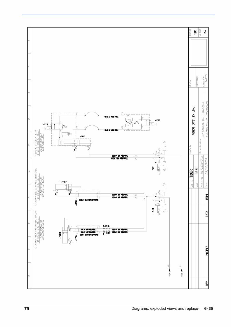
Pneumatic diagram
6- 3579 Diagrams, exploded views and replace-

MEP S.p.A.
6- 36 80Use and maintenance manual C370- 2SI

6- 3781 Diagrams, exploded views and replace-
List of components
Item Type Description Board Sh Q.ty’- R1 ’043.0199 4X1/8 TURNING ELBOW JOINT ’=BMMEP 101 1’- R2 4X1/8 TURNING ELBOW JOINT ’=BMMEP 101 1’- R3 4X1/8 TURNING ELBOW JOINT ’=BMMEP 101 1’- R4 4X1/8 TURNING ELBOW JOINT ’=BMMEP 101 1’- RG1 ’043.0204 8X1/4 - CL 6521 ELBOW COUPLING ’=BMMEP 102 1’- R5 8X1/4 - CL 6521 ELBOW COUPLING ’=BMMEP 101 1’- R6 8X1/4 - CL 6521 ELBOW COUPLING ’=BMMEP 101 1’- RM1 ’043.0206 4X1/8 - CL 6511 HEXAGONAL COUPLING ’=BMMEP 101 1’- RM4 4X1/8 - CL 6511 HEXAGONAL COUPLING ’=BMMEP 101 1’- RM3 4X1/8 - CL 6511 HEXAGONAL COUPLING ’=BMMEP 101 1’- RM6 4X1/8 - CL 6511 HEXAGONAL COUPLING ’=BMMEP 101 1’- RG10 ’043.0208 8X1/8 - CL 6521 ELBOW COUPLING ’=BMMEP 102 1’- RG9 8X1/8 - CL 6521 ELBOW COUPLING ’=BMMEP 102 1’- RD3 ’043.0225 DA 4X8 - CL 6800 REDUCTION ’=BMMEP 102 1’- RD4 DA 4X8 - CL 6800 REDUCTION ’=BMMEP 102 1’- RY1 ’043.0235 Y BRANCHING 4 MM ’=BMMEP 102 1’- RY2 Y BRANCHING 4 MM ’=BMMEP 102 1’- RM2 ’043.0281 1/8 M 8/8 - CL 2543 SLEEVE ’=BMMEP 101 1’- RM5 1/8 M 8/8 - CL 2543 SLEEVE ’=BMMEP 101 1’- IR1 ’043.0290 1/4 QUICK COUPLING ’=BMMEP 100 1’- T3 ’043.0301 8X6 BLACK RILSAN HOSE ’=BMMEP 102 8’- T4 ’043.0302 4X2.7 BLACK RILSAN HOSE ’=BMMEP 102 12’- VR1 ’043.0601 VMS 114- 1/4 08 VALVE ’=BMMEP 100 1’- GT10 ’022.0181 COVERING MM 10 ’=BMMEP 101 0.6’- GT11 COVERING MM 11 ’=BMMEP 101 1’- PN1 ’034.0747 PNEUMATIC PANEL TI 350 SX ’=PPCV 102 1’- S14 ’043.0143 PS1P1091 PNEUMATIC PRESSURE SWITCH ’=PPCV 100 1’- RG3 ’043.0198 4X1/4 TURNING ELBOW JOINT ’=PPCV 102 1’- RG2 ’043.0204 8X1/4 - CL 6521 ELBOW COUPLING ’=PPCV 102 1’- RG4 8X1/4 - CL 6521 ELBOW COUPLING ’=PPCV 102 1’- RG5 8X1/4 - CL 6521 ELBOW COUPLING ’=PPCV 102 1’- RG7 ’043.0208 8X1/8 - CL 6521 ELBOW COUPLING ’=PPCV 102 1’- RG8 8X1/8 - CL 6521 ELBOW COUPLING ’=PPCV 102 1’- RG12 8X1/8 - CL 6521 ELBOW COUPLING ’=PPCV 102 1’- RG11 8X1/8 - CL 6521 ELBOW COUPLING ’=PPCV 102 1’- RT1 ’043.0222 CL 2033 1/4 CROSS JOINT ’=PPCV 102 1’- RD1 ’043.0231 1/8- 1/8 MF CL 2520 REDUCTION ’=PPCV 102 1’- RD2 1/8- 1/8 MF CL 2520 REDUCTION ’=PPCV 102 1’- RD5 1/8- 1/8 MF CL 2520 REDUCTION ’=PPCV 102 1’- RD6 1/8- 1/8 MF CL 2520 REDUCTION ’=PPCV 102 1’- RG6 ’043.0251 M.F. ELBOW RLA 8 - 1/8 - CL 2020 ’=PPCV 102 1’- NY1 ’043.0275 A2- 1/4 - CL 2500 CONICAL NIPPLE ’=PPCV 102 1’- NY2 A2- 1/4 - CL 2500 CONICAL NIPPLE ’=PPCV 102 1’- T1 ’043.0301 8X6 BLACK RILSAN HOSE ’=PPCV 102 0.5’- T2 ’043.0302 4X2.7 BLACK RILSAN HOSE ’=PPCV 102 0.5’- MN1 ’043.0552 MANOMETER 0 40 ’=PPCV 102 1’- MN2 MANOMETER 0 41 ’=PPCV 102 1

MEP S.p.A.
6- 38 82Use and maintenance manual C370- 2SI
Item Q.tyShBoardDescriptionType’- GTA ’043.0564 FR 1/4 20- 08 ’=PPCV 100 1’- RP1 ’043.0580 MR 1/4 O- 8 REGULATOR ’=PPCV 100 1’- K30 043.0608 +
022.5805 WAY 1/8 PVLB111618 PARKER VALVE + COIL 24VAC ’=PPCV 101 1
’- K32 6 WAY 1/8 PVLB111618 PARKER VALVE + COIL 24VAC ’=PPCV 101 1’- SL2 043.0202 1/8” G BRASS SILENCER ’=PPCV 102 1’- SL3 1/8” G BRASS SILENCER ’=PPCV 102 1’- SL4 1/8” G BRASS SILENCER ’=PPCV 102 1’- SL1 1/8” G BRASS SILENCER ’=PPCV 102 1

MEP S.p.A.
6- 40 83Use and maintenance manual C370- 2SI
Exploded views
This part of the manual contains detailed exploded views of the machine whichcan help to gain a deeper knowledge of how it is made.
Head unit

6- 4184
Code Description Description Quantity001.4802 TESTA OPERATRICE GEAR BOX TI 370 CNC 1,000001.4810 FLANGIA SECONDO STADIO FLANGE TI 370 CNC 1,000007.3363 FLANGIA ESTERNA OUTER FLANGE TI 350 - 370 0 98 1,000007.3359 BOCCOLA RIPRESA CORSA BUSHING TI 350 1,000007.3537 PIASTRINO PULILAMA COMPLETO BLADE BRUSH CLEANER SUPPORT 1,000007.3615 GHIERA SECONDO STADIO TI 370 CNCFE SECOND STAGE RING NUT TI 370 CNCFE 1,000007.3616 GHIERA FIX CUSCINETTO RING NUT CN- TI 350- SH 280*320 1,000007.6301 DISTANZIALE SECONDO STADIO TI370CNC SECOND STAGE SPACER TI 370 CNCFE 1,000007.6302 DISTANZIALE IØ STADIO TI 370 CNCFE FIRST STAGE SPACER TI 370 CNCFE 1,000007.6303 DISTANZIALE CORONA II STADIO TI 370 SECOND STAGE BRONZE SPACER TI 370 1,000007.6341 TAMPONE IØ STADIO RIDUZIONE FIRST STAGE PAD TI 370 1,000007.6362 ALBERO MOVIMENTO TESTA TI 370 CNCFE HEAD MOVEMENT SHAFT TI 370 CNCFE 1,000007.6363 ALBERO D.35 IIØ STADIO TI 370 CNCFE SECOND STAGE SHAFT D.35 TI 370 CNCFE 1,000007.6381 FLANGIA PORTAMOLLA RICHIAMO TESTA SPRING HOLDER FLANGE TI 370 CNC 1,000010.0352 GHIERA AUTOBLOCCANTE 35X1,5 SELF- LOCKING RING NUT 35X1,5 2,000010.0913 MOLLA SOLLEVAMENTO TESTA HEAD SPRING TI 350/370 1,000010.1201 VITERIA E BULLONERIA SCREWS AND BOLTS 5,000010.1556 STAFFA FISSAGGIO MANIGLIA TESTA GEAR BOX HANDLE FIX BRACKET TI 370 CNC 1,000010.1653 PERNO FLANGIA FLANGE PIN 0 7 X 22 2,000010.1654 PERNO FLANGIA FLANGE PIN 0 9 X 19 2,000010.2101 RUOTA SOLLEVAMENTO TESTA HEAD LIFTING WHEEL TI 350 1,000010.7005 ANELLO SEEGER DIAM. 17 0 17 SEEGER RING (010.7005) 1,000010.7008 ANELLO SEEGER DIAM. 25 0 25 SEEGER RING (010.7008) 1,000010.7123 CHIAVETTA 10 X 8 X 25 10 X 8 X 25 KEY 3,000010.7204 DADO M8 M8 SCREW NUT (010.7204) 1,000010.7226 DADO AUTOBLOCCANTE M6 M6 SELF- LOCKING SCREW NUT 1,000010.7409 GRANO VCE P.CIL. 8 X 10 8 X 10 CYLIND.POINT VCE GRUB SCREW 4,000010.7456 GRANO VCE P.CON. 8 X 16 8 X 16 CONICAL POINT VCE GRUB SCREW 2,000010.7603 RONDELLA DIAM. 6 0 6 WASHER (010.7603) 6,000010.7605 RONDELLA DIAM. 10 0 10 WASHER (010.7605) 1,000010.7768 SPINA ELASTICA DIAM. 6 X 40 ELASTIC PIN DIAM. 6 X 40 1,000010.7830 VITE BUTON 5 X 10 5 X 10 BUTON SCREW (010.7830) 3,000010.7858 VITE TCEI 5 X 10 TCEI 5 X 10 SCREW 6,000010.7868 VITE TCEI 6 X 12 TCEI 6 X 12 SCREW 4,000010.7870 VITE TCEI 6 X 16 TCEI 6 X 16 SCREW (010.7870) 2,000010.7871 VITE TCEI 6 X 20 TCEI 6 X 20 SCREW (010.7871) 4,000010.7877 VITE TCEI 6 X 45 TCEI 6 X 45 SCREW 4,000010.7890 VITE TCEI 8 X 12 TCEI 8 X 12 SCREW (010.7890) 1,000010.7894 VITE TCEI 8 X 25 TCEI 8 X 25 SCREW (010.7894) 3,000010.7895 VITE TCEI 8 X 30 TCEI 8 X 30 SCREW 1,000010.7963 VITE TE 8 X 25 TE 8 X 25 SCREW (010.7963) 4,000010.7986 VITE TE 12 X 35 TE 12 X 35 SCREW (010.7986) 1,000011.0018 .ALBERO PORTADISCO TI 370 BLADE SHAFT TI 370 1,000016.0134 CARTER RUOTA SOLLEVAMENTO TESTA DI GEAR BOX WHEEL COVER TI 370 CNCFE 1,000016.0458 COPERCHIO MOLLA SPRING COVER TI 350/370 1,000016.0555 GUIDA SPAZZOLA PULILAMA TI 370 SX BAND BRUSH GUIDE TI 370 SX 1,000025.0069 CUSCINETTO 32007X BEARING 32007X 2,000025.0071 CUSCINETTO 626 2RS BEARING 626 2RS 2,000025.0195 ANELLO TENUTA 62X45X10 G VITON 45X62X10 G VITON CLAMPING RING 1,000025.0194 ANELLO TENUTA OR 176 G VITON 176 G VITON OR CLAMPING RING 1,000025.0249 ANELLO TENUTA OR 201- 2- 351 O RING 201- 2- 351 1,000025.0552 SPAZZOLA PULILAMA 6X25 030 GG53 BAND BRUSH 6X25 030 SHARK 1,000025.0953 CUSCINETTO 6307 BEARING 6307 1,000025.0954 CUSCINETTO 30207 BEARING 30207 2,000025.0955 CUSCINETTO 3203 BEARING 3203 1,000025.0956 CUSCINETTO 6005 BEARING 6005 1,000025.0958 CUSCINETTO 3204 A 2RS BEARING 3204 A 2RS 1,000025.1022 RUOTA ELIC.CILINDR.ALBERO MANDRINO SPINDLE WHEEL TI 370 CNCFE 1,000025.1024 RUOTA ELICOIDALE CILINDR.IIØSTADIO HELICOIDAL WHEEL TI 370 CNCFE 1,000

MEP S.p.A.
6- 42 85Use and maintenance manual C370- 2SI
Code QuantityDescriptionDescription025.1026 CORONA ELICOIDALE Z 20 MN 5 BRONZE GEAR Z 20 MN 5 TI 370 1,000034.0905 TAPPO OLIO TAO/3 1/2” NERO TAO/3 1/2” BLACK OIL CAP 1,000034.1106 VOLANTINO DIAM.100 A 6 LOBI O 100/6 LOBE HANDWHEEL TIGER 1,000034.1211 MANIGLIA GN- 565- 20- 128.SW GN- 565- 20- 128.SW HANDLE 1,000

6- 4386
Control panel

MEP S.p.A.
6- 44 87Use and maintenance manual C370- 2SI
Code Description Description Quantity010.7830 VITE BUTON 5X10 5 X 10 BUTON SCREW (010.7830) 4.000
010.8135 DADO M20 BASSO M20 LOW NUT 1.000
010.8978 VITE TCEI 3X20 3X20 TCEI SCREW 1.000
016.0722 QUADRO COMANDI CONTROL PANEL TI 352 - 372 SX 1.000
022.0124 CUSTODIA ISOLANTE E- PKZO-GR HOUSING W.RED HANDLE 1.000
022.0125 BLOCCO LUCCHETTABILE SBV- PKZO- E LOCKABLE BLOCK 1.000
022.1287 INTERRUTORE PKZM0- 10 SWITCH PKZM0- 10 (THERMAL) 1.000
034.1169 MANOPOLA DI REGOLAZIONE MONOGIRO FEED RATE KNOB (W/ SEMICIRCLE HOLE) 1.000
043.0587 REGOLATORE DISCESA TESTA HEAD DOWN STROKE REGULATOR 1.000
044.1252 VALVOLA RIGENERATRICE CILINDRO CYLINDER REGENERATING VALVE 1.000
022.0555 SGANCIATORE U- PKZ0 V.400.50 COD.73138 RELEASER U- PKZ0 V.400.50 1.000
022.0378 CONNETTORE V.1406 X BOBINA RAC VALVO-LA
CONNECTOR F.REGENERATOR VALVE COIL 1.000
022.0615 BOBINA V24 RAC X VALVOLA RIGENERATRI-CE
COIL X CYLINDER VALVE 1.000
031.2073 CONSOLLE DI PROGRAMMAZIONE PROGRAMMING CONSOLLE 1.000
016.1674 CORNICE QUADRO COMANDI CONSOLE FRAME 1.000
034.1166 MANOPOLA X COMANDO POTENZIOM.22 MM. KNOB 22 MM F. POTENTIOMETER 1.000

6- 4588
Motor assembly

MEP S.p.A.
6- 46 89Use and maintenance manual C370- 2SI
Code Description Description Quantity001.4808 FLANGIA MOTORE VERTICALE VERTICAL MOTOR FLANGE 1,000
010.0352 GHIERA AUTOBLOCCANTE 35X1,5 SELF- LOCKING RING NUT 35X1,5 1,000
010.7006 ANELLO SEEGER DIAM. 20 0 20 SEEGER RING 1,000
010.7123 CHIAVETTA 10 X 8 X 25 10 X 8 X 25 KEY 1,000
010.7604 RONDELLA DIAM. 8 0 8 WASHER (010.7604) 4,000
010.7967 VITE TE 8 X 40 TE 8 X 40 SCREW 4,000
019.2002 KW 2,6/1,84 8/4P.C112 B.14 V.380 KW 4 4P.B.14 GR112 S6 60% V.230- 400/240- 1,000
025.0067 CUSCINETTO 3207 BEARING 3207 1,000
025.0811 BOCCOLA A RULLINI DHK 4020 HK ROLLER BUSHING DHK 4020 HK 1,000
025.0957 CUSCINETTO 6204 BEARING 6204 1,000
025.1027 VITE SENZA FINE MN 5 WORM SCREW MN 5 1,000
025.1028 RUOTA ELIC.CIL.VITE S/F CONDOTTA HELICOIDAL WHEEL Z 39 MN 2 1,000
025.1029 RUOTA ELIC.CIL.ELBERO MOTORE PIGN. HELICOIDAL WHEEL Z 35 MN 2 1,000
034.0902 TAPPO OLIO CENTRALINA IDRAULICA ”SFP 1/2”” RED OIL CAP” 1,000
025.0622 GUARNIZIONE MOTORE CN 275- 350 MOTOR GASKET CN 275- 350 1,000

6- 4790
Vice

MEP S.p.A.
6- 48 91Use and maintenance manual C370- 2SI
Code Description Description Quantity001.4805 SUPPORTO MORSA M.1755 VICE SUPPORT TI 370 CNC 1,000
001.4817 .SCORREVOLE MORSA TI 370 SX VICE BACK STOP TI 370 SX 1,000
007.3229 TASSELLO X BATTUTA SCORR. ANTIBAVA FIXING PLATE TI- FC 1,000
007.3354 LARDONE MORSA VICE GIB TI 350 1,000
007.4651 GRANO BLOC PIANO GIREVOLE LOCKING GRUB SCREW SH 200- CB330- 450 1,000
007.6333 PERNO BLOCCAGGIO MORSA TI 370 VICE LOCKING PIN TI 370 1,000
010.0242 VITE MORSA VICE SCREW 420X24 TI350MA- SX- AX 1,000
010.0509 GANASCIA MORSA VICE JAW TI 350 N.S. 1,000
010.0512 GANASCIA ANTIBAVA ANTI BURR JAW TI 350 1,000
010.0854 SUPPORTO SCORREVOLE GANASCIA ANTI- SIDING ANTIBURR JAW SUPPORT 1,000
010.1201 VITERIA E BULLONERIA SCREWS AND BOLTS 1,000
010.7203 DADO M6 M6 SCREW NUT (010.7203) 7,000
010.7204 DADO M8 M8 SCREW NUT (010.7204) 1,000
010.7410 GRANO VCE P.CIL. 8 X 16 8 X 16 CYLIND.POINT VCE GRUB SCREW 2,000
010.7427 GRANO VCE P.CIL. 8 X 12 8 X 12 CYLIND.POINT VCE GRUB SCREW 1,000
010.7453 GRANO VCE P.CON. 6 X 30 6 X 30 CONICAL POINT VCE GRUB SCREW 7,000
010.7454 GRANO VCE P.CON. 8 X 8 8 X 8 CONICAL POINT VCE GRUB SCREW 1,000
010.7456 GRANO VCE P.CON. 8 X 16 8 X 16 CONICAL POINT VCE GRUB SCREW 2,000
010.7481 GRANO VCE PUNTA PIANA 8 X 35 8X35 FLAT POINT VCE GRUB SCREW 1,000
010.7603 RONDELLA DIAM. 6 0 6 WASHER (010.7603) 7,000
010.7604 RONDELLA DIAM. 8 0 8 WASHER (010.7604) 1,000
010.7605 RONDELLA DIAM. 10 0 10 WASHER (010.7605) 3,000
010.7859 VITE TCEI 5 X 12 TCEI 5 X 12 SCREW (010.7859) 2,000
010.7868 VITE TCEI 6 X 12 TCEI 6 X 12 SCREW 2,000
010.7893 VITE TCEI 8 X 20 TCEI 8 X 20 SCREW (010.7893) 3,000
010.7924 VITE TCEI 10 X 30 TCEI 10 X 30 SCREW (010.7924) 2,000
034.0205 VOLANTINO MORSA VPRA/125 HANDWHEEL SH + PH 1,000
034.1001 LEVA A SCATTO 8 MA LEVER 8 MA PK55 1,000
034.1002 LEVA A SCATTO 10 MA LEVER 10 MA 1,000
043.0033 CILINDRO VOLAMPRESS 125- 8 AIR CYLINDER 125- 8 1,000
043.0199 ATTACCO A GOMITO GIREV.4X1/8 CL6521 4X1/8 TURNING ELBOW JOINT 2,000

6- 4992
Turntable

MEP S.p.A.
6- 50 93Use and maintenance manual C370- 2SI
Code Description Description Quantity001.4804 PIATTAFORMA ROTANTE ROTATING PLATFORM 1.000
001.4819 COLONNA PORTANTE SUP.COLLUM 1.000
010.7934 VITE TCEI 12 X 50 TCEI 12 X 50 SCREW 4.000
010.2122 CREMAGLIERA TI 370 CNCFE RACK TI 370 CNCFE 1.000
010.7873 VITE TCEI 6 X 30 TCEI 6 X 30 SCREW 2.000
016.0133 CARTER CREMAGLIERA SOLLEVAMENTO TE-STA
RACK COVER TI 370 CNC 1.000
010.7830 VITE BUTON 5 X 10 5 X 10 BUTON SCREW (010.7830) 2.000
010.7204 DADO M8 M8 SCREW NUT (010.7204) 2.000
010.7965 VITE TE 8 X 35 TE 8 X 35 SCREW (010.7965) 2.000
001.4806 SQUADRO MORSA TI 370 CNC VICE BACK STOP TI 370 CNC 1.000
010.7926 VITE TCEI 10 X 45 TCEI 10 X 45 SCREW 2.000
010.7932 VITE TCEI 10 X 110 TCEI 10 X 110 SCREW (010.7932) 1.000
001.3723 SUPPORTO CILINDRO SUPPLEMENTARE SUPPORT TI 350 SX- AX- CNC 1.000
010.0319 VITE 8.8 TESTA CILINDRICA ESAGONO IN-CASSATO 10X140 TI
SCREW 8.8 10X140 TI 2.000
010.7924 VITE TCEI 10 X 30 TCEI 10 X 30 SCREW (010.7924) 1.000
010.0542 GANASCIA MORSA DESTRA TI 370 RIGHT VICE JAW TI 370 1.000
010.0511 GANASCIA MORSA SINISTRA TI 350 LEFT VICE JAW TI 350 1.000
010.7868 VITE TCEI 6 X 12 (010.7868) TCEI 6 X 12 SCREW 6.000
001.3709 STAFFA BLOCCAGGIO CILINDRO SUPPLE-MENTARE
BRACKET TI- CB 330- 400- 450 MOD.706 1.000
010.7606 RONDELLA 0 12 0 12 WASHER (010.7606) 1.000
010.7941 VITE TCEI 12 X 35 TCEI 12 X 35 SCREW 2.000
043.0041 CILINDRO MORSE 50X10 0 40 L.150 DOP-PIOEFFETTO
50X10 DOUBLE EFFECT VICE CYLINDER 1.000
043.0199 ATTACCO A GOMITO GIREVOLE 4X1/8 CL 6521 4X1/8 TURNING ELBOW JOINT 2.000
007.3234 BOCCOLA GANASCIA X CILINDRO SUPPLEMENTARE
JAW BUSHING TI- CB 1.000
010.7455 GRANO VCE PUNTA CONICA 8 X 10 8 X 10 CONICAL POINT VCE GRUB SCREW 1.000
010.7470 GRANO VCE PUNTA PIANA 6 X 35 6X35 FLAT POINT VCE GRUB SCREW 3.000
010.7661 RONDELLA SPESSORE DIAM. 6 X 3 THICKNESS WASHER DIAM. 6X3 (010.7661) 9.000
010.1851 BOCCOLA PER CARTER DISCO TI O 20 BLADE COVER BUSHING TI 0 20 3.000
010.7226 DADO AUTOBLOCCANTE M6 (010.7226) M6 SELF- LOCKING SCREW NUT 3.000
010.2828 GUIDA PATTINO HGW25- HC- 2- R0465- E30_ZB- H
SLIDE GUIDE HGW25- HC- 2- R0465- E30_ ZB-H
1.000
010.2829 GUIDA PATTINO HGW25- HC- 2- R0490- E30_ZB- H
SLIDE GUIDE HGW25- HC- 2- R0490- E30_ZB- H 1.000
010.7872 VITE TCEI 6 X 25 (010.7872) TCEI 6 X 25 SCREW (010.7872) 16.000
010.7871 VITE TCEI 6 X 20 (010.7871) TCEI 6 X 20 SCREW (010.7871) 16.000
007.3218 BATTUTA FINECORSA TESTA IN BASSO LIMIT SWITCH STOP TI370- TI372- TI402 1.000
010.7979 VITE TE 10 X 50 TE 10 X 50 SCREW 1.000
010.7205 DADO M10 M10 SCREW NUT (010.7205) 1.000

6- 5194
Fix plattform assembly

MEP S.p.A.
6- 52 95Use and maintenance manual C370- 2SI
Code Description Description Quantity001.3111 DISTANZIALE BATTUTA STOP SPACER 1,000
001.4803 PIATTAFORMA FIXED PLATFORM 1,000
007.3202 BOCCOLA X BATTUTA BUSHING FOR STOP 1,000
007.4534 PERNO DI CENTRO CENTRE PIN 1,000
007.4651 GRANO BLOCCAGGIO PIANO ROTANTE LOCKING GRUB SCREW 1,000
007.6331 PERNO BLOCCAGGIO PIANO GIREVOLE ROTATING TABLE LOCKING PIN TI 370 1,000
010.0311 VITE TCEI M12X16 BATT.PIANO GIREVO. SCREW M12X16 ROTATING TABLE STOP 2,000
010.0352 GHIERA AUTOBLOCCANTE 35X1,5 SELF- LOCKING RING NUT 35X1,5 1,000
010.0370 GHIERA 5S 30X1,5 RING NUT 5S 30X1,5 1,000
010.0451 TIRANTE BATTUTA TAGLI MISURA CUT TO MEASURE STOP TIE ROD 1,000
010.0711 ASTA MILLIM.CROMATA MM.600 FIL. M16 MM SCALE 6000 1,000
010.0801 RULLO TIPO ROLLER 304011 0 24 1,000
010.0802 SUPPORTO PER RULLO ROLLER SUPPORT 2,000
010.1201 VITERIA E BULLONERIA SCREWS AND BOLTS 1,000
010.7009 ANELLO SEEGER DIAM. 30 0 30 SEEGER RING 1,000
010.7204 DADO M8 M8 SCREW NUT 2,000
010.7221 DADO M16 BASSO M16 LOW SCREW NUT 2,000
010.7450 GRANO VCE P.CIL. 6 X 6 6 X 6 CYLINDRICAL POINT VCE GRUB 2,000
010.7480 GRANO VCE PUNTA PIANA 8 X 30 8 X 30 FLAT POINT VCE GRUB SCREW 2,000
010.7481 GRANO VCE PUNTA PIANA 8 X 35 8X35 FLAT POINT VCE GRUB SCREW(010.7481
1,000
010.7604 RONDELLA DIAM. 8 0 8 WASHER 6,000
010.7607 RONDELLA DIAM. 16 0 16 WASHER 2,000
010.7890 VITE TCEI 8 X 12 TCEI 8 X 12 SCREW 2,000
010.7932 VITE TCEI 10 X 110 TCEI 10 X 110 SCREW 4,000
010.7961 VITE TE 8 X 20 TE 8 X 20 SCREW 4,000
010.7965 VITE TE 8 X 35 TE 8 X 35 SCREW 2,000
016.1034 BRACCETTO APPOGGIA BARRA BAR SUPPORT ARM 1,000
025.0080 GABBIA ASSIALE A RULLINI AXK 3552 AXIAL CAGE WITH ROLLERS AXK 3552 1,000
025.0082 RALLA AS 3552 CENTER PLATE AS 3552 2,000
034.1001 LEVA A SCATTO 8 MA PK55 LEVER 8 MA PK55 2,000

6- 5396
Blade guard unit

MEP S.p.A.
6- 54 97Use and maintenance manual C370- 2SI
Code Description Description Quantity010.0908 MOLLA CARTER DISCO BLADE COVER SPRING 1,000
010.7603 RONDELLA DIAM. 6 0 6 WASHER 3,000
010.7868 VITE TCEI 6 X 12 TCEI 6 X 12 SCREW 1,000
010.7872 VITE TCEI 6 X 25 TCEI 6 X 25 SCREW 1,000
016.0135 CARTER DISCO TI 370 SX BLADE GUARD 1,000
016.0408 PARASCHIZZI ANTERIORE TI 370 SX FRONT SPLASH SHIELD 1,000
028.0121 RACCORDO 3/8- 17 CL 2601 JOINT 3/8- 17 CL 2601 3,000
028.0394 TUBO LOOC LINE 1/2 ART. 59861 LOOC LINE HOSE 1/2 1,000
028.0399 UGELLO 0 12,7 - 1/2 ART. 59863 NOZZLE 0 12,7 - 1/2 2,000
028.0404 RACCORDO 3/8 NPT LOOC LINE 1/2 FITTING 3/8 NPT 2,000
034.0088.1 PROTEZIONE LEXAN CARTER LAMA BLADE GUARD 1,000
034.1110 VOLANTINO DIAM.30 M6 X 10 O 30 M6 X 10 HANDWHEEL 1,000
043.0237 RACCORDO A T FFF 3/8 3/8 T JOINT 1,000
043.0238 RACCORDO A GOMITO FF 3/8 3/8 ELBOW JOINT 1,000
043.0653 RUBINETTO M/F 3/8 CL 6310 M/F 3/8 CL 6310 TAP 3,000

6- 5598
Base assembly

MEP S.p.A.
6- 56 99Use and maintenance manual C370- 2SI
Code Description Description Quantity010.7603 RONDELLA DIAM. 6 0 6 WASHER (010.7603) 2,000
010.7830 VITE BUTON 5 X 10 5 X 10 BUTON SCREW (010.7830) 6,000
010.7871 VITE TCEI 6 X 12 TCEI 6 X 20 SCREW (010.7871) 2,000
013.0137.1 PIEDISTALLO TI 372 SX EVO STEEL BASE TI 372 SX EVO 1,000
016.0186 RACCOGLITORE ACQUA TI 370 SX WATER COLLECTOR TI 370 SX 1,000
022.0211 RACCORDO RAPIDO SEM PG 13,5 RAPID JOINT SEM PG 13,5 2,000
022.0213 RACCORDO RAPIDO SEM PG 21 RAPID JOINT SEM PG 21 1,000
022.0234 PRESSACORDONE 3246 NERO PG 13,5 CORD PRESSER 1,000
022.0244 CONTRODADO 3217B GRIGIO PG 13 LOCK NUT 3217B GREY PG 13,5 3,000
022.0324 PASSACAVI 24 INC.MM.2.5 FAIRLEADS 24 INC.M M.2.5 2,000
022.2721 CONTRODADO PG 21 LOCK NUT PG 21 1,000
028.0010 PISTOLA COOLANT PISTOL SH- TI 8966 1,000
028.0121 RACCORDO 3/8- 17 CL 2601 JOINT 3/8- 17 CL 2601 2,000
028.0260 ELETTROPOMPA ELECTROPUMP 230- 400.50 HZ SPV33 1,000
034.0901 TAPPO LIVELLO OLIO 1/2 ”GAS. 1/2” GAS. OIL LEVEL CAP 1,000
034.0905 TAPPO OLIO TAO/3 1/2” NERO TAO/3 1/2” BLACK OIL CAP 1,000
043.0143 PRESSOSTATO PNEUM.PS1P1091 PS1P1091 PNEUMATIC PRESSURE SWITCH 1,000
043.0183 RACCORDO A Y 90Ø MASCHIO 3/8 Y MALE JOINT 3/8 1,000
043.0186 RACCORDO FEMMINA 1/2 AQUASTOP 1/2 WATERASTOP FEMALE JOINT 1,000
043.0198 ATTACCO A GOMITO GIREV.4X1/4 CL6521 4X1/4 TURNING ELBOW JOINT 1,000
043.0202 ATTACCO A ESAGONO 8X1/8 - CL 6511 8X1/8 - CL 6511 HEXAGONAL COUPLING 4,000
043.0204 ATTACCO A GOMITO 8X1/4 - CL 6521 8X1/4 - CL 6521 ELBOW COUPLING 3,000
043.0205 ATTACCO A ESAGONO 8X1/4 - CL 6510 8X1/4 - CL 6510 HEXAGONAL COUPLING 1,000
043.0206 ATTACCO A ESAGONO 4X1/8 - CL 6511 4X1/8 - CL 6511 HEXAGONAL COUPLING 4,000
043.0222 RACCORDO A CROCE CL 2033 1/4 CL 2033 1/4 CROSS JOINT 1,000
043.0235 BIFORCAZ. A Y TUBO 4MM. 24275320 Y BRANCHING 4 MM 2,000
043.0251 GOMITO MF 1/8 M.F. ELBOW RLA 8 - 1/8 - CL 2020 1,000
043.0263 RACCORDO A GOMITO M/F ZINCATO 3/4 3/4 ELBOW JOINT 1,000
043.0275 NIPPLO CONICO A2- 1/4 - CL 2500 A2- 1/4 - CL 2500 CONICAL NIPPLE 1,000
043.0281 MANICOTTO 1/8 M 8/8 - CL 2543 1/8 M 8/8 - CL 2543 SLEEVE 2,000
043.0290 INNESTO RAPIDO 1/4 GHIOTTO 13/A 1/4 QUICK COUPLING 1,000
043.0473 SILENZIATORE IN OTTONE 1/8” CL 2921 ”1/8”” CL 2921 BRASS SILENCER” 4,000
043.0552 MANOMETRO DIAM. 40 MANOMETER 0 40 1,000
043.0564 FR 1/4 20- 08 FR 1/4 20- 08 1,000
043.0601 VALVOLA VMS 114- 1/4 08 VMS 114- 1/4 08 VALVE 1,000
043.0608 VALVOLA 5 VIE 1/8 PVLB111618 PARKER 5 WAY 1/8 PVLB111618 PARKER VALVE 2,000
010.7884 VITE TCEI 4X40 TCEI 4 X 40 SCREW 2,000
016.1190 PANNELLO PNEUMATICO PNEUM.EQUIPMENT WIRING PANEL 1,000
022.0238 PRESSACAVO PG7 CABLE PRESSER PG 7 BS01 1,000
022.2702 DADO PG7 NUT PG 7 BL01 1,000
043.0180 RIDUZIONE M3/4 F3/8 REDUCTION M 3/4- F 3/8 1,000
043.0231 RIDUZIONE MF1/8 1/8- 1/8 MF CL 2520 REDUCTION 2,000
010.1809 CHIUSURA SPORTELLO DOOR LOCKING WIT KEY 1,000
016.2455 SPORTELLO PIEDISTALLO TI 372 SX EVO STEEL BASE DOOR TI 372 SX EVO 1,000
010.1893 CERNIERA SPORTELLO PIEDISTALLO N.T. PROTECTION DOOR HINGE N.T. 1,000
010.7475 GRANO VCE PUNTA PIANA 8 X 8 8 X 8 FLAT POINT VCE GRUB SCREW 1,000

6- 57100
Cylinder unit

MEP S.p.A.
6- 58 101Use and maintenance manual C370- 2SI
Code Description Description Quantity001.4816 SUPPORTO AGGANCIO CILINDRO SUPPORT 1,000
007.3216 BATTUTA FINECORSA LIMIT SWITCH STOP 1,000
007.6332 PERNO FORCELLA FORK PIN 1,000
010.1103 FORCELLA 16 X 1,5 16 X 1,5 FORK 1,000
010.8954 VITE TE 8 X 80 8 X 80 TE SCREW 1,000
010.1559 STAFFA FISSAGGIO CILINDRO CYLINDER FIX BRACKET 1,000
010.1560 STAFFA TRASCINAMENTO POTENZIOMETRO POTENTIOMETER BRACKET 1,000
010.1561 STAFFA AGGANCIO CILINRO CYLINDER FIX BRACKET 1,000
010.7204 DADO M8 M8 SCREW NUT 1,000
010.7221 DADO M16 BASSO M16 LOW SCREW NUT 1,000
022.0378 CONNETT.BOBINA VALV. RIGENERATRICE CONNECTOR F.REGENERATOR VALVE COIL 2,000
022.0615 BOBINA X VALVOLA RIGENERATRICE CIL. COIL X CYLINDER VALVE 1,000
022.1801 POTENZIOMETRO LINEARE LWH225- 024309 LINEAR POTENTIOMETER 1,000
043.0204 ATTACCO A GOMITO 8X1/4 - CL 6521 8X1/4 - CL 6521 ELBOW COUPLING 1,000
043.0340 RONDELLA RAME 13X19X1,5- 1/4 13X19X1,5- 1/4 COPPER WASHER 2,000
044.0501 NIPPLO NP 1/4 IDRAULICO NP 1/4 HYDRAULIC NIPPLE 2,000
044.1251 VALVOLA RIGENERATRICE CILINDRO CYLINDER REGENERATING VALVE 310SX- AX 1,000
044.1257 VALVOLA DI CARICO CILINDRO CYLINDER LOADING VALVE 1,000
043.0823 UNITA’ IDROPNEUM.0 63 C.230 HYDROPNEUMATIC UNIT 0.63 C.230 1,000

7- 1
Adjustments
The steps for setting the electronic, mechanical, and pneumatic systems on SXmodels, are illustrated in this chapter. By following these instructions you can“customise” your machine to carry out the type of cut to be made, thus optimisingthe time taken for this operation.
Displaying and editing the set- up parametersThe machine set- up parameters may be programmed directly from the controlconsole.
" Power up the machine at the main switch located on the left hand side.
" Press simultaneously and in sequence the keys SET- UP and ON;
7

MEP S.p.A.
7- 2 103Use and maintenance manual C370- 2SI
" Once inside the SET- UP menu, use the following keys to navigate throughthe different menu screens:
FCTA Head Do-wnstroke Limit
FCTI Head Up-stroke Limit
CONSOLE orFOOT PEDAL
START
Head “down” key
" The FCTA key (Y) allows you to change parameter settings in increments ofone unit.
" The FCTI key (") instead has two functions: it is used to save parameter set-tings and navigate inside the SET- UP menu.
" The console or foot pedal START selection key allows you to zero the currentparameter setting.
" The key “Y- ” enables the cursor to return to the previous positions." To quit the SETUP parameters, press in sequence and simultaneously theSETUP and ON keys.
Set language parameter" PressY to change the display messages presentation language.
ENGLISH
LANGUAGE:
Set parameter for machine type" Press" to display the parameter for the machine type. Press theY key tochange machine type; each press of the key corresponds to a different ma-chine configuration.
TIGER 352 SX-EVO
MACHINE MOD.:
Semiautomatic-Dynamic and Manual operation setting
This function is not included for this machine model. Thus, do not consider thisvideo page and go to the next one by the key".
NO
MAN&SAD CYCLE:

7- 3104 Adjustments
Pedal control setting (optional)
" Press" to display the pedal control parameter, then pressY to set the pres-ence (YES) or the absence (NO) of this optional.
PEDAL START
NO
Inverter presence settings
This function is not included for this machine model. Thus, do not consider thisvideo page and go to the next one by the key".
NO
INVERTER:
Blade speed proximity settings
This function is not included for this machine model. Thus, do not consider thisvideo page and go to the next one by the key".
NO
BLADE SPEED PROXY:
Minimal lubrication system settings
" Press" to display the min. lubrication system parameter, then pressY to setthe presence or the absence of this optional, choosing YES or NO.
NO
MIN. LUBR.:
FCTI / FCTA digital output enabling setting
" Press the" key to display the parameter enabling or disabling the outputs ofthe positions FCTI (backward head limit switch) and FCTA (forward headlimit switch). Press theY key to set YES or NO.
NO
FCTI/A OUTPUTS

MEP S.p.A.
7- 4 105Use and maintenance manual C370- 2SI
Disc stop setting
" Press the" key to display the disc stop parameter, then pressY to set thevalue of this parameter.If the value is set as 2, the disc never stops;if it is set as 1, the disc stops in the RHLS (rear head limit switch) point;if the value is set as 0, the disc stops in the FHLS (forward head limit switch)point.
NEVER/FCTI/FCTA: 0
BLADE MOTOR OFF
Cutting vice opening setting
" Press the" key to display the parameter indicating if the shearing vice mustopen when the head is in the FCTI (backward head limit switch) point or inthe FCTA (forward head limit switch) point; pressY to set the value as 0(vice opening in FCTA), or as 1 (vice opening in FCTI).
FCTA/FCTI: 1
CUTTING VICE OPENING
Cutting vice opening/closing time setting
" Press the" key to display the parameter indicating the time between the viceclosing and the cut start and between the cut end and the vice re- opening.PressY to change this value, ranging between 0.0 and 9.9 seconds.
TIME = 2.0
VICE OPENING/CLOSING
Machine maximum power input setting
" Press the" key to display the parameter and then increase or reduce the val-ue with theY key.
BLADE = 07.0
I MAX MOTOR
The factory set values are relative to the motor installed on the machine.
Measurement unit setting
" Press the" key to display the parameter, then pressY to set the value as 0or 1, to choose the measurement unit expressed respectively in pounds or
N.B.

7- 5106 Adjustments
kilograms.
FIPS/MKS = 0
MEASUREMENT UNIT
Setting minimum blade tensioning
This function is not included for this machine model. Thus, do not consider thisvideo page and go to the next one by the key".
BLADE = 0000
MIN. BLADE
Display backlighting time setting
" Press the" key to display the LCD backlighting time parameter, then presstheY and" keys to set the time expressed in minutes.
TIME = 00
LCD BACKLIGHTING
Cutting head stroke
The operating head covers the space between the rear position and the forwardposition that can be defined in the SET- UP with the FHLS- RHLS parameter.Anyway, it is necessary to check if the operating head actually and not virtuallycovers the cutting width between its structural limits of rear head limit switch andforward head limit switch.The adjustment is aimed at setting the value of the head current position both atRHLS (rear limit 254) and at FHLS (forward limit 054) displayed with the linearpotentiometer.To get this result carry out the following adjustment:
HEAD POSITION = 100
FCTI/FCTA LIMIT
" press in sequence and simultaneously the ⇑ key and the key for the head low-ering (Y+), to position the cutting head completely upwards;
When the cutting head is totally up, the potentiometer stem is inside the poten-N.B.

MEP S.p.A.
7- 6 107Use and maintenance manual C370- 2SI
tiometer body. In this position make sure that the adjustment nut for the stemmax. stroke is at about 4 mm from the lower base of the linear potentiometer.
4mm
" Open the control board removing the frame and pull the keyboard out of theconsole;
" Identify the board IUD/IUV of the controller M30 to adjust the potentiome-ter indicated by the arrow in the following image:
" The IUD/IUV board includes three adjacent potentiometers. Adjust the ad-justment screw of the potentiometer indicated by the arrow by a screw- driverat a value of 254; the obtained variation is displayed on the machine.
HEAD POSITION = 254
FCTI/FCTA LIMIT
" Position the console again in its seat and re- install the frame fastening it byscrews.
" Press in sequence and simultaneously the keys ⇑ and RHLS to store the ob-tained value.

7- 7108 Adjustments
" Set the FHLS point, taking the head completely down, pressing in sequenceand simultaneously the ⇑ key and the key for the head lowering (Y- ).
HEAD POSITION = 054
FCTI/FCTA LIMIT
" Press in sequence and simultaneously the keys ⇑ and FHLS to store the ob-tained value.
" Press simultaneously and in sequence the keys SET- UP and ON to quit theSETUP parameters:
" Test to make sure it is functioning correctly.
Software version and total use time of the machine
" This parameter indicates the installed software version and the total workingtime of the machine.
TT = 0000:00
M30 v01.01 40- 07
Adjusting the display brightness
If external factors like changing ambient lighting conditions in the machineinstallation site, affect visibility, adjust the brightness of the control and program-ming console display. This is very important since the operator must be able toclearly read the display messages at all times.
" To adjust the brightness, first remove the screws fixing the front console pan-el. The photo below illustrates the M30 controller card on which the bright-ness potentiometer is marked by an arrow.
" Using a screwdriver, rotate the potentiometer until the required displaybrightness is obtained.

MEP S.p.A.
7- 8 109Use and maintenance manual C370- 2SI
Air treatment unitThe pneumatic circuit on the machine activates the shearing vice by means of thevolampress cylinder, and the machine’s cutting head by means of the oil pneuma-tic cylinder. The compressed air is conditioned and purified as it enters by atreatment unit that, when regulated, stabilises the pressure at around 6 Bar,depending on the pressure in use in the factory. In any case, the pressure can beset where material may be deformed or may prove to be unstable during cutting,and the vice is positioned at 2÷3 mm from the workpiece before it is closed. Onerequirement is for the the user of this machine to provide a plant in his factorywith the characteristics shown in Chapter 4. The figure below shows an explodedview of the air treatment unit. The operating pressure of the vice shown on thepressure gauge is set by rotating the handle indicated by the arrow.
Pressure gange Vice pressure adijustment Knab
Cutting head operating pressureThe cutting head cuts the material pushed by a hydro pneumatic cylinder, with adownstroke speed set by the oil flow regulator on the control panel. The regulator
has a scale of 0 to 9 and is indicated on the panel by the symbol : when this is
rotated clockwise, the downstroke speed is reduced, when it is turned counter-clockwise the speed is increased.

7- 9110 Adjustments
Cutting head actuator cylinder (CPT)
Replenishing the head cylinderWhen the oil level in the compensator tank falls it must be topped up. The figurebelow illustrates the various components of the cutting head cylinder.
Linear potentiometer
Oil filler cap
Compensator tank
A drop in oil level is identified by the position of the ring on the rod in relation tothe oil reservoir, which in normal conditions should be approximately 30 mm.
Compensator cylinderIf this is not the case, top up the oil level as follows:" keep the head in the FCTI position (fully up);" unscrew and remove the filler cap on the side of the cylinder;

MEP S.p.A.
7- 10 111Use and maintenance manual C370- 2SI
" then, using an electric or manual pump like the one shown in the figure, fillthe cylinder with AGIP ATF DEXRON hydraulic oil or one with similar char-acteristics;
" when the rod protrudes by 30÷45 mm, the correct oil level has been restored;" run a few dummy cutting strokes in semi- automatic mode to expel any airfrom inside the circuit. If cutting head movement is not linear and constant,and the rod retracts by several millimetres, top up the oil level again.
ViceThe shearing vice, which is a standard fitting on the C370- 2SI, is equipped withan anti- chip device, adjustable cross positioning, and is driven by a pneumaticcylinder known as the “volampress”. These elements will be dealt with one by onein the following.
Adjusting the vice playAny play which develops between the slideway and the slide gibs on the vice mustbe compensated by adjusting the grub screws setting the distance between the giband lead screw, proceeding as follows:" slacken all the locknuts on the grub screws in the slide, holding the screws stillusing an Allen key;
" move the vice to its fully open position;
" adjust the slight pressure exerted by the grub screws on the gib, starting withthe first two in contact with the lead screw.

7- 11112 Adjustments
" adjust these two grub screws and tighten the relative lock nuts, keeping thescrews still with an Allen key;
" close the vice until the other two grub screws coincide with the lead screw;" repeat this adjustment on the gib grub screws for the entire length of theslideway;
" at the end of the operation, use the handwheel to move the slide backwardsand forwards, identifying the zones where the grub screws exert greater pres-sure on the gib;
" repeat the adjustments if necessary.
Rag prevention deviceThe vice is fitted as standard with a rag prevention device that serves to supportthe material and prevent the formation of ragged edges at the end of the cut. Toadjust the rag prevention device transversely:" loosen the release lever (1) located above the vice slide;" movement the rag prevention device arm to the right or left;" tighten the release lever.
1
22
4
3
To adjust the longitudinal position of the vice jaw, proceed as follows:" tighten the cutting vice completely;" slacken the two screws located to the side of the rag prevention device (2- 3);" slacken the nut that locks the grub screw;" adjust the longitudinal position of the rag prevention vice jaw by slackening ortightening the grub screw (4) until the position of the rag prevention jaw isaligned with that of the cutting jaw;

MEP S.p.A.
7- 12 113Use and maintenance manual C370- 2SI
Adjusting operating head travelDuring the cutting cycle the cutting head stroke is limited by the FCTI (HeadUpstroke Limit) and FCTA (Head Downstroke Limit), set electronically on thecontrol panel, as described on Page 5. The cutting head has a mechanical limitingswitch that determines its downstroke:" to change this setting, two hexagonal spanners must be used, one to keep thenut in position, and the other to tighten and loosen the stop screw.
DiscThe HSS cutting discs can be used for any kind of cut since they combine goodlevels of toughness and elasticity thanks to various coatings, along with a goodcutting resistance. The discs are made of a single piece of Tungsten- Molybde-num super- rapid steel with a hardness of about 64±1 HRC. A special character-istic of the discs during cutting is the excellent finish of the cut surfaces.
Adjusting the turntable stopsIf it found that a cut at 0° , 45° or 60° does not correspond exactly to the angleshown on the turntable, the right and left stops will need adjusting. The proce-dures for correcting and adjusting the disc stops at 0° , 45° and 60° right and leftare described below. Sequence of operations for 0° stop:" release the turntable by means of the release lever on the right hand side ofthe table;

7- 13114 Adjustments
" adjust the nut using two 10 mm spanners until the stop corresponds to the 0°notch; loosen the lock nut and adjust; tighten the lock nut while holding thebolt steady; check and repeat if necessary.
Sequence of operations for 45° right stop:" release the turntable by means of the release lever on the right hand side ofthe table;
" remove the screw that functions as the 0° stop so as to reach the 45° right po-sition;
" adjust the nut using two 10 mm spanners until the stop corresponds to the 45°notch; loosen the lock nut and adjust;
To adjust the 45° and 60° left stops, proceed as for the other positions, butremove the 45° stop screw (shown by the arrow in the photo) to reach the 60° leftstop, in the same way as for the 45° right stop described above.

MEP S.p.A.
7- 14 115Use and maintenance manual C370- 2SI
Changing the bladeAs we have already said, this machine uses different kinds of blades according tothe material to be cut. The procedures described below, however, also apply inthe event of wear or breakage of the blade. To replace the blade, proceed asfollows:" switch off the machine and position the head so that the disc is easily accessi-ble;
" the machine is equipped with a vertical pneumatic vice that can be movedaway from the guard by unfastening the screw fixing it to the support;
" remove the screw with knob to free the plexiglass guard cover and lift it off ina vertical direction;
" use a 19 mm spanner to slacken the hexagonal screw that locks the disc, turn-ing the spanner in the direction of rotation of the disc; remove the old discand insert the new one, making sure that the centering pins fit correctly intothe holes in the disc;

7- 15116 Adjustments
Make sure that the teeth on the cutter blade are facing in the direction of rota-tion. When changing the tool, turn the cutter blade until drive is engaged toeliminate any backlash in the drive pins.
" Tighten the lock nut and refit all guards and any other components you mayhave removed to facilitate installation.
Adjust the position of the blade- cleaning brush, or replace it when worn.
If disks are fitted with diameters less than 370 mm, adjust the head mechani-cal stop screw as described above.
Attention
N.B.
Attention

MEP S.p.A.
7- 16 117Use and maintenance manual C370- 2SI
Adjusting the position of the blade- cleaning brush
When the cutter disk is not clean enough, check the blade- cleaning brush forwear and if it’s working correctly. The figure below illustrates how the brushshould be adjusted if need be." Loosen the screw highlighted in the drawing, and remove the protection;
" adjust the position of the blade in relation to the teeth, as shown;

8- 1
Maintenance andchoice ofconsumables
C370- 2SI is built to be sturdy and long- lasting It has no need of any specialmaintenance, though, like all other tools, it needs adjusting from time to time,especially if not regularly looked over or used without due care.
This chapter, therefore, is intended as a guide for those who want to look afterthe machine and get the most out of it for as long as possible.
The role of the operator
The person operating and maintaining the machine must follow these instructionsfor his own safety, as well as for the safety of other personnel, and in the interestsof machine productivity:
H check that his own work and that of the other operators of the machine alwayscomplies with the relevant safety standards. Therefore, check that the safety de-vices are in position and work perfectly and that personal safety requirements arecomplied with.
H Ensure that the working cycle is efficient and guarantees maximum productivity,checking:
n the functions of the main components of the machine;
n the sharpness of the blade and coolant flow;
n the optimum working parameters for the type of material.
H Check that the quality of the cut is that required and that the final product does nothave any machining defects.
8

MEP S.p.A.
8- 2 119Use and maintenance manual C370- 2SI
Maintenance requirements
H All ordinary and extraordinary maintenance must be carried out with the powerswitched off and the machine in emergency condition.
H To guarantee perfect operation, all spare parts must be Hyd-Mech originals.
H On completion of maintenance works, ensure that the replaced parts or any toolsused have been removed from the machine before starting it up.
H Any behaviour not in accordance with the instructions for using the machine maycreate risks for the operator.
H Therefore, read and follow all the instructions for use and maintenance of the ma-chine and those on the product itself.
General maintenance
Daily
The daily maintenance operations to carry out on the machine are as follows:
" remove all swarf from the machine (do not use compressed air or fluffy rags);
" empty the swarf drawer (the swarf collection drawer is located in the base andis accessible through the front opening panel);
" top up the lubricant/coolant fluid level;
" check the wear of the blade and change if necessary;
" check the blade cleaning brush, clean it and reposition it: if worn, replace.
Weekly
The weekly maintenance operations are as follows:
" remove all swarf from the machine;
" clean the vice and lubricate all the joints and sliding surfaces using a goodquality oil;
" check the oil level in the transmission box; if necessary fill through cap.
" check the vice sliding mechanism. If it is not smooth or is subject to side play,adjust as described in chapter 7.
Monthly
This section lists the operations to be carried out for the monthly maintenance ofthe machine.
" check that the machine performs cuts perpendicular to the work surface; ifnot, contact our technical service centre;
" check that the blade is at right angles to the workpiece rest shoulder; if not,contact our technical service centre;
" check that the 0 degree notch on the fixed work table is in line with the gradu-ation on the turntable. If not, adjust as described in chapter 7;

8- 3120 Maintenance and choice of consumables
" check the precision of the 45° right and 45° and 60° left stops; if they are notadjusted correctly, proceed as described in chapter 7;
" clean thoroughly the water tank and the electric pump filter.
Consumable materials
It is essential to use specific oils for the pneumatic and lubricant/coolant circuits.The oils suitable for each of these circuits are listed below.
Oils for pneumatic and hydraulic circuit
The machine is supplied with AGIP ATF DEXRON oil, ISO and UNI grade FD22. The oils are used with the air treatment unit and the hydro- pneumaticcylinder. However the following oils can be regarded as compatible or havingequivalent specifications:
API Cis 22 - ARAL Dural SR 22 - CASTROL Hyspin AWS 22 ESSO Spinesso22 - IP Hydrus oil 22 - TOTAL Azolla ZS 22 VALVOLINE ETC 22 - MOBILVelocite oil D - Mobil DTE 22 MOBIL ATF 220 - OLIO FIAT HTF 22 - Q8Haydn 22 - SHELL Tellus oil 22 - BP AUTRAN GM- MP
Oils for lubrication/coolant liquid
The oil used for the lubrication/coolant fluid in the machine is CASTROLSyntolin TFX. Though there are no specific standards for these types of oils,Hyd- Mech considers that CASTROL SyntolinTFX is the best product available with regard to quality:price ratio. Nevertheless,the following oils of similar characteristics can be said to be compatible:
AGIP NB 200 - SHELL Lutem TT - IP Utens Fluid- F
Finally, one particular blade manufacturer (LENOX) recommends and supplies acoolant under the name of LENOX BAND- ADE SAWING FLUID.
Coolant tank:- tank capacity 80 litres- oil concentration 5- 6%
Oils for spray mist system (optional)
The used oil type for the optional spray mist system is BLASER Vascomill 22.The following oils can also be said to have similar characteristics and aretherefore compatible:
UNIST Coolube 2210 - FUCHS Plantocut Micro Plus 27
- tank capacity Lt. 1
Oils for transmission box
The machine is supplied with SHELL Omala S4 WE 320 oil, ISO and UNIsymbol 460. However the following oils can be regarded as compatible or with

MEP S.p.A.
8- 4 121Use and maintenance manual C370- 2SI
equivalent characteristics:
API DT 320 - CASTROL ALPHA SP 320 - AGIP Blasia 320 S
Transmission box:- capacity lt. 4,8

9- 1
Cutting speed andchoice of tools
The cut speed is determined by the speed the cutter disc rotates at, and by thefeed speed. This chapter describes the various cutting speeds of which thestandard and special machine configurations are capable.
Cutting speed
C370- 2SI, standard machine
The standard version with inverter and 4- pole motor achieves this cutting speedrange:
H 15 ÷ 150 rpm.
Choice of bladeThe different types of cutter disks that the C370- 2SI can mount must, however,have the following main characteristics:H “Fine tooth pitch”: for thin wall materials such as sheet steel, tubes and profiles;
H “Coarse tooth pitch”: for large cross- sections; for soft materials (aluminium alloysand soft alloys in general).
Tooth pitch
The choice of the most suitable tooth pitch depends on various factors:
H the size of the section;
H the hardness of the material;
H wall thickness.
Solid sections call for discs with a coarse tooth pitch, while small cross- sectionsrequire blades with finer teeth. This is because when cutting walls of smallcross- section (1÷7 mm) profiles, it is important that the number of teethactually making the cut should not be too small, otherwise the effect obtained willbe one of tearing rather than of swarf removal, leading to a large increase inshearing stress. On the other hand, when cutting thick materials or solid sectionsusing an excessively fine tooth pitch, the swarf collects as a spiral inside the gullet,and since fine tooth pitches have small gullets, the accumulated swarf will exceedthe gullet capacity and press against the walls of the workpieces, resulting in poorcutting (same situation with soft materials), greater shearing stress and hencebreakage of the blade.
9

MEP S.p.A.
9- 2 123Use and maintenance manual C370- 2SI
Choice of tooth pitch T as a function of cross- section to be cut for light alloy solid pieces and profiles
S S sp
S in mm. Pitch T S and sp in mm. Pitch T
10 4- 5 10 sp = 0,5 3
30 6- 8 30 sp = 1,5 4 - 5
50 8- 10 50 sp = 2,5 5 - 6
70 10- 12 70 sp = 3,5 6- 7
90 12 90 sp = 4,5 7 - 8
130 16 130 sp = 6,5 8
KEY:S = diameter or width of the solid piece to be cut in mm;sp = thickness of the wall to be cut in mm;T = tooth pitch in mm.
A larger pitch should be chosen when, as a result of the shape of the piece to becut, the cross- section at any given point exceeds the average cross- section givenabove.
Types of swarf:
H Very fine or fragmented swarf indicates that the downstroke speed and/or cuttingpressure is too low.
H Thick and/or blue swarf indicates that the blade is overloaded.

9- 3124 Cutting speed and choice of tools
H Long coils of swarf indicate ideal cutting conditions.
Cutting and feeding speed
The cutting speed, in m/min, and the head feeding speed, in cm2/min, are limitedby the amount of heat generated near to the points of the teeth. If the headfeeding speed is too high, the cut will not be straight in either the vertical or thehorizontal plane. As we have already said, the cutting speed depends on thestrength (kg/mm2) and hardness (HRC) of the material and the dimensions of thethickest section. The feeding speed depends on the cross- section of the material.Solid or thick- walled materials (thickness > 5 mm), can therefore be cut at highspeed providing there is sufficient swarf removal by the blade, while thin- walledmaterials such as tubes or thin profiles must be cut with a low feeding speed. Anew blade requires a wearing- in period, during which time a feeding speed ofabout half normal speed should be used.
Lubricant/coolant
The lubricating/cooling fluid must ensure that the blade teeth and material in thearea of the cut do not overheat. Furthermore, the quantity and pressure must besufficient to remove the swarf from the cutting zone. The fluid must be anexcellent lubricant, such that prevents abrasion of the teeth and welding of theswarf to the teeth themselves (seizing).
Blade structure
The circular blades most frequently used for cutting- off machines are HSS-DMo5/M2 consisting of a single piece and characterised by a high level oftoughness and a good cutting resistance. With non- ferrous materials it is normalto use circular blades with brazed hard metal (HM) cutting edges, which offerexcellent resistance to wear but low resistance to impact, which in any case is notgenerally a problem with non- ferrous materials.
Key
Mo Molybde-num
Ni Nickel Si Silicon V Vanadium W Tungsten
Al Aluminium C Carbon Co Cobalt Cr Chromium Mn Manganese
C W Mo V Co HRCCr
0,47 1,00 6,37 1,00 0,12 45- 50
TYPE OF BLADE
HSS-DMO 5/M2
The numbers in the columns indicate the % content of the element in the steel.N.B.

MEP S.p.A.
9- 4 125Use and maintenance manual C370- 2SI
Types of blades
The blades fitted on the C370- 2SI have dimensions 370x32x3 and are made ofHSS DMO5 since the machine is intended for cutting ferrous materials. Inaddition to the size and pitch of the teeth, the blades also have other geometriccharacteristics according to their particular use:
H tooth sharpening, which in this case may be BW with alternate raked tooth or Cwith roughing tooth raked on both sides and non- raked finishing tooth;
H tooth pitch, the distance between the crests of two subsequent teeth (tooth pitch =T).
Tooth shape
”C” TYPE SHARPENING (HZ)Coarse toothing with roughing tooth raked on both sides and non- raked finishingtooth. The roughing tooth is about 0.3 mm higher.
Coarse toothing with roughing tooth and finishing tooth. Used in saws with pitchgreater than or equal to 5 mm for cutting ferrous and non- ferrous materials withsolid or solid- profiled sections.
”BW” TYPE SHARPENING DIN 1838- UNI 4014Coarse toothing with teeth alternately raked to the right and left.
Toothing generally used on cutting- off machines for cutting ferrous and alloymaterials with tubular and profiled sections.
The C370- 2SI uses 370x3x32 discs made of HSS DMo5 and teeth with type Csharpening for hollow sections; for solid sections it uses 370x3x32 discs, againmade of HSS. The tooth pitch is also important as shown in the table below.Disc selection table for TIGER machine. Other disc characteristics are: dimen-sions: internal hole diam. 32 mm, distance between fixing holes 63 mm, toothshape type C.

9- 5126 Cutting speed and choice of tools
TIGERMODEL
D. T Z D. T Z D. T Z
372 370 5 220 370 8 140 370 12 90
This table can be used to facilitate the choice of toothing since it takes intoaccount both the size of the material to be cut and the diameter of the disc to beused.
Solidsection
S
D
S
Hollowsection
D 200 225 250 275 300 315 350 370 400 425 450 500
S1030507090110130150D1030507090110130150
tz
tz
tz
tz
tz
tz
tz
tz
tz
tz
tz
tz
tz
tz
tz
tz
tz
tz
tz
tz
tz
tz
tz
tz
5130
6100
6100
880
3200
3200
4160
5130
5140
6120
6120
880
890
1070
5160
6128
6128
8100
8100
1080
5180
6140
6140
8110
8110
1090
1090
1270
6160
8120
8120
1090
1090
1280
1280
1470
7140
8120
8120
10100
10100
1280
1280
1470
1280
1470
9120
10110
11100
1290
1290
1480
1280
1470
1280
1670
10110
11100
11100
1290
1290
1480
1290
1480
1480
1670
10120
12100
12100
1490
12100
1490
1490
1680
90 80
10130
12110
12110
1494
12110
1494
1494
1684
94 84
10140
12120
12120
14100
12120
14100
14100
1690
100 90
10150
12130
12130
14110
12130
14110
14110
16100
110 100
3220
3220
4180
5140
5140
6120
3250
3250
4200
5160
5160
6128
3280
3280
4220
5180
5180
6140
6140
8110
4220
5180
5180
6160
6160
8120
8120
10100
4240
5200
5200
6160
6160
7140
7140
8120
8120
10100
5200
6180
6180
7160
7160
8140
8140
9120
9120
10110
5220
7160
7160
8140
7160
8140
8140
9120
9120
10110
9120
10110
6200
7180
7180
8160
8160
9140
9140
10120
9140
10120
6220
7190
7190
8160
8160
9150
9150
10130
9150
10130
6230
7200
7200
8180
8180
9160
9160
10140
9160
10140
6260
7220
7220
8200
8200
9170
9170
10150
9170
10150
14 16 14 16 14 16 14 16

MEP S.p.A.
9- 6 127Use and maintenance manual C370- 2SI
Blade selection table with respect to cutting speed and downstroke speed
R = 350- 500 N/mmq
R = 500- 700 N/mmq
R = 750- 950N/mmq
R = 950- 1000 N/mmq
R = 950- 1300 N/mmq
R = 500- 800 N/mmq
R = 500- 800 N/mmq
R = 200- 400 N/mmq
R = 300- 500 N/mmq
R = 200- 350 N/mmq
R = 600- 900 N/mmq
R = 200- 400 N/mmq
R = 400- 700 N/mmq
R = 300- 800 N/mmq
R = 300- 600 N/mmq
R = 400- 600 N/mmq
Tmm
Tmm
Tmm
Tmm
Tmm
Tmm
Tmm
Vtrpm
Avmm/1’
Vtrpm
Avmm/1’
Vtrpm
Avmm/1’
Vtrpm
Avmm/1’
Vtrpm
Avmm/1’
Vtrpm
Avmm/1’
Vtrpm
Avmm/1’
10-20
20-40
40-60
60-90
90-110
110-130
130-150
208550
160745
15045
1401240
1301440
1101635
100183090
188430
130630
12025
1101225
1101420
100162090161580
158420
110620
11018
100111750141580161470161260
1263156041560145091450121345141345141240
10629353933930682888251072512722
12842050619451845111740141540161435161235
15642050619451845111740141540161435161235
128425
100623
10022901120801419
880161770161660
22106
1100
18008
1000
1700
12
900
1600
16
800
1400
18
700
1300
20
600
110020
500
900
2085
200
4007
180
40010
160
35012
160
30014
140
30016
130
25016
130
250
20106
400
6008
350
60011
300
55014
250
55017
200
50018
150
50020
120
400
1585
400
8007
400
70010
350
70012
300
60014
250
60016
200
50018
150
400
1284
120
1608
110
1508
100
1401090
1301270
1101460
100165090
16165
600
11006
600
110010
550
1000
12
550
90016
500
90018
500
80018
450
800
12165
500
7007
400
60010
350
60012
350
50016
300
50018
300
40018
200
400
188450
160445
150645
1401045
1301240
1101435
100163090
188319
130418
120518
110617
110616
10081690101580
158235
130333
120430
110530
110528
1006269062480
109
86
48
88
R = 300- 600 N/mmq
αγ
Cutting section (in mm)
CUTTINGANGLE
RECOMMENDEDCUT-
TINGPARAMETERS
Recom
mended
lubrificantsEmulsion
-cutting
oilCutting
oilEmulsion
Mild steel
Medium steel
Hard steel
Super hard steel
Hardened and tem-pered steel
Austenitic stainless st
Martensiticstainless
Grey iron
Aluminium and alloy
Copper
Hard bronze
Phosphor bronze
Brass
Alloyed brass
Titanium and alloys
Profiles and tubeswith wall thickness0.05 DProfiles and tubeswith wall thickness0.25 D
Aluminium and alloy

9- 7128 Cutting speed and choice of tools
Classification of steels
The tables on this page provide users with information on materials to cut,enabling their classification with respect to hardness and consequently the correctblade to use.
AISI
DIN
BS
UNI
C22
-C35
C45
C10
-C15
C60
45CrSi9
34CrMo5
35CrMo4
20NcCrMo2
X8CrNiM
o1713
XCrNi1910
X6CrNi1810
X12
Cr13
100Cr6
52NcCrMoKU
CK22
-CK3
CK45
CK10
-CK15
CK60
17115
17221
34CrMo
36NiC
r6
1880
XC95
2750
(280W18)
4401
4301
4001
4845
210Cr46
17100
100Cr6
56NiC
rMoV7
En2C-En6
En8
En32
A-En328
En9
4360
970-1955
En18
B
En19
B
En111
En362
En100D
DX
B2
18%W
1507
-825
1501
-845
En58
E
En56
A
En58
G
A1
A2
En36
4360
-50
A3706
-1.2.3.
En20
A
En31
1022
-1035
1040
1010
-1015
1060
1065
5135
-5145
4135
3135
4315
8645
W1
L6
T1
1310
316
304
410
309S
D3
M13
3310
-3315
ASTMA-36/68
52100
BrinellH
BHRB
kg/mm2
160-170
160-180
150-175
160-180
160-180
180-205
180-200
200-230
190-230
200-225
190-220
150-190
190-230
217-248
217-248
160-200
130-170
150-200
215-240
200-230
160-220
200-230
160-180
160-180
190-215
210-230
150-200
60-100
70-90
95-120
70-100
34-87
84-89
81-87
84-89
84-89
89-94
89-93
93-99
91-99
93-98
91-97
80-91
91-99
97-102
97-102
84-93
74-86
80-93
97-101
93-99
84-91
93-99
84-89
84-89
91-97
96-99
80-93
56,5
49
51-69
56,5
55-59
55-61
51-59
55-61
55-61
61-69
61-67
67-77
64-77
67-75
64-74
51-64
64-77
73-83
73-83
55-67
45-58
51-67
73-81
67-77
55-64
67-77
55-61
55-61
64-73
71-77
51-67
36 32 34-42
36
Types
ofsteel
Phosphorbronze
Aluminiumbronze
Siliconbronze
Manganesebronze
Hardness

MEP S.p.A.
9- 8 129Use and maintenance manual C370- 2SI
Classification of steels
1311
1572
1650
1880
2120
2255
2541
2230
2258
2310
-12
2754
-55
2550
2710
2324
2333
2343
2353
1015
-1035
1040
-1064
1770
-1880
1335
-1345
4130
-4140
4337
-4340
50100-52100
6145
-6152
8630
-8645
D-2,D-3
S-1
201,202
302,304
314,316
317
C22
-C35
20Mn5-28
Mn6
CK22
-CK50
CK60
-CK101
36Mn5
Cm45
-Cm55
25CrMo4-42
CrMo4
40NiC
rMo6
40NiC
rMo73
34CrNiM
o6,100Cr6
X210Cr12
X155CrVMo121
60W
CrV7
55NiC
rMoV6
X2CrNi189
X5CrNi189
G-X2CrNi189
X15
CrNiSi2520
X5CrNiM
o1812
X5CrNiM
o1713
050A20
080M46
-50
120M19
150M28
060A40
-060A96
070M55
080A40
-080A62
1717
CDS110
708A37
708M40
735A50,534
A99
817M40
311typu
6i7
BD2,BD3
BS1
304S15
304C12
316S16
317S16
XC18
XC38
H1
20M5
XC60
-XC75
40M5
XC42
H1
25CD4
35NCD6
50CV4
100C6
Z160CVD12
Z200C12
55NCVD7
Z2CN18.10
Z6CN18.09
Z3CN19.10
Z12
CNS25.20
Z6CND17.12
304S12
C15
-C35
C22
Mn
C28
Mn
C45
-C60
40NiC
rMo2-40
NiC
rMo7
30NiC
rMo8-35
NiC
rMo6KB
50CrV4,100Cr6
X205Cr12
KU
X155CrVMo121KU
55W
CrV8Ku
55NiC
rMoV6
X2CrNi18.11
X5CrNi18.10
G-X2CrNi19.10
X16
CrNiSi2520
X5CrNiM
o1713
X5CrNiM
o1815
25CrMo4-42
CrMo4
XC55
H1
42CD4
Material
SS
Svezia
AISI
U.S.A.
DIN
Germania
BS
Inghilterra
UNI
Italia
AFNOR
Francia
Carbonsteels
Carbonsteels
Alloysteel
Stainlesssteel
Stainlesssteels
Toolsteel
Toolsteels
Alloysteels

10- 1
Troubleshooting
This chapter describes the inspection and troubleshooting procedures for theC370- 2SI. Regular inspections and efficient maintenance are essential to ensureyour machine gives you a long, trouble- free service life. The chapter is dividedinto two sections: the first being dedicated specifically to TROUBLESHOOTINGBLADE AND CUTTING PROBLEMS, while the second TROUBLESHOOT-ING section concerns troubleshooting general machine operating faults. Takentogether they form a comprehensive troubleshooting guide which will enable youto follow a methodical procedure for solving any problem.
Troubleshooting blade and cutting problems
PROBLEM PROBABLE CAUSE SOLUTION
Cuts not at 90 degrees or angled ' Head speed too high .Reduce head speed' Disc with worn teeth .Replace disc' Orthogonality of disc toworkpiece rest shoulder
.Adjust the position of theblade so that it is at right an-gles to the workpiece restshoulder using the 0° ad-juster pin; then set the stopsat 45° right and left using theappropriate screws.
' Perpendicularity of disc towork surface
.Contact our Assistance Of-fice
' Cutting speed too low .Increase cutting speed.' Broken teeth .Check the hardness of the
material being cut
Teeth breaking ' Incorrect lubricant/coolant flu-id
.Check the water and oilemulsion; check that theholes and hoses are notblocked; direct the nozzlescorrectly.
10

MEP S.p.A.
10- 2 131Use and maintenance manual C370- 2SI
SOLUTIONPROBABLE CAUSEPROBLEM
Teeth breaking ' Material too hard .Check the cutting speed,feed speed and disc pres-sure parameters and the typeof disc you are using.
' Disc not worn- in correctly .With a new disc it is neces-sary to start cutting at halffeeding speed. After thewearing- in period (a cuttingsurface of about 300 cm2 forhard materials and about1000 cm2 for soft materials)the cutting and feed speedscan be brought up to normalvalues.
' Disc with excessively finetooth pitch
.The swarf wedges into thebottom of the teeth causingexcessive pressure on theteeth themselves.
' New blade inserted in a par-tially completed cut.
.The surface of the cut mayhave undergone local ther-mal alteration, making itharder: when starting workagain, use a lower cuttingspeed and head feed speed.A tooth from the old blademay be left in the cut: checkand remove before startingwork again.
' Workpiece not clamped firmlyin place
.Any movement of theworkpiece during cutting cancause broken teeth: checkthe vice, jaws and clampingpressure.
' Vibration .Workpiece vibrates in thevice: check that the slide hasbeen adjusted correctly;check the clamping pressureand if necessary increase.
Rapid tooth wear ' Head speed too slow .The blade runs over the ma-terial without removing it: in-crease head speed.
' Cutting pressure too high .Reduce cutting pressure.' Cutting speed too high .The teeth slide over the ma-
terial without cutting it: re-duce the cutting speed.
' Insufficient coolant .Check the coolant level andclean piping and nozzles.
' Incorrect fluid concentration .Check and use the correctconcentration.

10- 3132 Troubleshooting
SOLUTIONPROBABLE CAUSEPROBLEM
Rapid tooth wear ' Material defective .The materials may presentaltered zones either on thesurface, such as oxides orsand, or in section, such asunder- cooled inclusions.These zones, which aremuch harder than the blade,cause the teeth to break: dis-card or clean these materials.
Broken blade ' Head speed too high .Reduce head speed.' Teeth in contact with materialbefore starting the cut
.Always check the position ofthe blade before starting anew job.
' Insufficient coolant .Check the coolant level andclean piping and nozzles.
' Vibrations .Workpiece vibrates in thevice: check that the slide isregulated correctly; check theclamping pressure and if nec-essary increase.
Troubleshooting
This section deals with the problems which may occur during machine operation.The M30 controller allows you to test all the machine’s electric and electronicdevices by checking the status of the input and output signals on the IUD/IUVcard (see Chapter 6).
The board IUD/IUV is inside the electric board.
Displaying the diagnostics menu
" Power the machine rotating the main switch on the left side of the control

MEP S.p.A.
10- 4 133Use and maintenance manual C370- 2SI
board;
" press simultaneously and in sequence the keys CHECK and ON;
Diagnostics systemOnce you have opened the diagnostics menu, a set of characters, each corre-sponding to an OUTPUT signal on the M30 controller, is displayed. For furtherinformation about the machine’s outputs, refer to the electrical and electronicdiagrams illustrated in Chapter 6 of this manual.
Testing the control console keyboard
Each console key has an identification number which is displayed on the diagnos-tics screen after the letter “K”, when the key is pressed. For example, whenpressing the key for the manual cycle (HAND key), the figure 12 is displayed nextto the letter ”K”:
Button id. number 010000000000 00KEY:00 INGRESSI:

10- 5134 Troubleshooting
if the figure K does not change pressing the key HAND, the probable malfunc-tioning is due to the console key that does not deliver power when closed.
List of IUD- IUV card INPUTS
010000000000 00KEY:00 INPUTS:
Foot pedal
Not usedOil level
Not used
Speed switchNot used
Not usedNot used
Emergency (01)Not used
Not used
Not used
Inverter failure
" the digits 0 and 1 shown in the display lower line indicate the status OFF (0)or ON (1) of each single input;
" Starting from the video page of the digital inputs, press the key “arrow up”once to display the list of the analogic inputs of the board IUD/IUV:
IML000
Analogic input no. 4 (not used)
Head position potentiometer
010 000PG NO ia4
048
Blade motor current
Not used
List of IUD- IUV card OUTPUTS
Blade motor
Inverter start
0100000000000000USCITE: SI=0 L=1
Lock solenoid valve
Min. lubrication solenoid valveCoolant electric pump
Cutting vice open
Head lowering
FCTI
FCTA
Bypass solenoid v.
Display backlighting
Not used
Not usedNot used
Not usedNot used
Not used
Not used

MEP S.p.A.
10- 6 135Use and maintenance manual C370- 2SI
" Starting from the video page of the digital inputs, press the key “arrow up”once to display the list of the outputs of the board IUD/IUV:
Current transformer
AMMETER TRANSFORMER FOR CHECKINGBLADE MOTOR ABSORPTIONIf the display of blade motor absorption doesn’t vi-sualise the current values any longer, it’s possible tocheck if the fault is relative to ”AMMETER TRAN-SFORMER”, to visualisation, to wiring, or to inputof IUV board.
Head position potentiometer
POTENTIOMETER OF HEAD CYLINDERTRANSDUCER (CUTTING HEAD POSITION)If, by moving the head upwards or downwards, thevalue visualised doesn’t change, you can check if theproblem is due to the transducer potentiometer, toconnections or to problems of the IUV. Move thehead manually and check that the value changes onthe display.
ANALOGIC INPUT NO. 3
ANALOGIC INPUT NO. 3Available for connecting optional instruments.
ANALOGIC INPUT NO. 4
ANALOGIC INPUT NO. 4Available for connecting optional instruments.
" the digits 0 and 1 shown in the display lower line indicate the status OFF (0)or ON (1) of each single output. Pressing the" orA key it is possible tomove the cursor till selecting the output to be checked. Pressing theY key itis activated or deactivated.
Machine alarms and emergenciesThe machine’s M30 controller notifies the operator of any alarm or emergencycondition which may occur during production by way of acoustic and visualsignals. This section lists the messages shown on the display.
PRESS RESETThis message is displayed during the initialisationphase after pressing the ON key
PRESS RESETThis message is displayed when the cutting start po-sition is lower than the previous position saved forthe cutting end position.
"Save both the FCTI and FCTA positions again.
HEAD NOT AT FCTIPRESS RESET
This message is displayed if the head is not posi-tioned at the FCTI position when the cycle isSTARTED.
"Return the head to the FCTI position beforeresuming the cycle

10- 7136 Troubleshooting
SELECT SPEEDPRESS RESEt
This message is displayed if the cycle is STARTEDwithout having first selected the cutting speed.
"Return the head to the FCTI position beforeresuming the cycle
STOP BUTTON PRESSEDPRESS RESET
This message is displayed if an operation is activat-ed before releasing the MUSHROOM HEADEMERGENCY STOP button.
"Release the EMERGENCY STOP button andpress RESET.
EMERGENCYBLADE GUARD OPEN
This message is displayed if the blade guard isopened, for example, to change the blade.
"Make sure the blade guard is closed."Check the safety limit switch."Check the connections.
EMERGENCYINVERTER FAILURE
This message is displayed if the machine isequipped with an INVERTER (optional). Press RE-SET to test the manual commands.
"Check the inverter contactor."Check the power supply voltage."Check the power phases and supply voltage ofthe blade motor."Check the connections.
EMERGENCYBLADE STOPPED
Displayed when the blade is jammed while cutting:
"Press RESET
EMERGENCYAIR PRESSURE
It is displayed when the air pressure from the net-work fails.
"Press RESET
EMERGENCYBLADE MOT I OVERC.
It is displayed when there is an overcurrent at theblade motor
"Press RESET
EMERGENCYBLADE TENSION
This message indicates a mechanical or electric/elec-tronic fault affecting the blade tensioning unit.
"Check the blade tension.
"Check the operation of the tensioning slide.
"Make sure the blade is correctly positioned onthe flywheels."Check the STRAIN GAUGE input on the IUVcard."Check the condition of the blade."Check the connections.
EMERGENCYERROR CODE: 01
RESETS OR INTERRUPTS NOT JUSTIFIABLE
EMERGENCYERROR CODE: 02
EEPROM NOT AVAILABLE

MEP S.p.A.
10- 8 137Use and maintenance manual C370- 2SI
EMERGENCYERROR CODE: 03
RAM TEST FAILED
EMERGENCYERROR CODE: 04
ROM TEST FAILED
EMERGENCYERROR CODE: 05
STATUS OR TEMPLATE NON- EXISTENT
EMERGENCYERROR CODE: 06
CUTTING CYCLE PHASE NON- EXISTENT
EMERGENCYERROR CODE: 07
EMERGENCY NOT DEFINED
EMERGENCYERROR CODE: 07
SERIAL 485 FAILURE
EMERGENCYERROR CODE: 07
SERIAL 422 FAILURE
EMERGENCYERROR CODE: 08
UNSTABLE DIGITAL INPUTS
EMERGENCYERROR CODE: 09
UNSTABLE BLADE (ch0) MOT ABSORBANAL. INPUT
EMERGENCYERROR CODE: 10
UNSTABLE HEAD (ch1) POSIT. P. ANAL. IN-PUT
EMERGENCYERROR CODE: 15
POWER FAILURE

11- 1
Accessory Installation
This chapter provides a list of the available accessories that can be fitted to thismachine, along with assembly instructions.
Supplementary pneumatic vice
As well as the vice fitted as standard on the machine, an additional pneumaticvice can also be fitted. The installation procedures are illustrated below:
H position the clamp to the right of the blade guard and tighten the feed screw lock-ing plate;
H connect the pneumatic hoses to the opening and closing unions on the pneumaticcylinder of the main pneumatic clamp using Y connectors.
Circular blade
The machine fits:
H circular blade HSS DMo5/M2 D. 370x32x3 for profiles.
See chapter 7 of this manual for cutter blade installation instructions.
11

MEP S.p.A.
11- 2 139Use and maintenance manual C370- 2SI
Roller tableH K40 roller table module for feed side, 1500 mm;H K40 roller table for discharge side, 1500 mm;
mm24
mm 190
Kg 35
mm 910-1040
H K40 roller table for discharge side, 3000 mm;H K40 roller table for discharge side, 4500 mm;H K40 roller table for discharge side, 6000 mm.H To fit the roller loading platform on the loading side, the machine has a bar- sup-
port arm that one end of the roller-way can be positioned on and then screwed inplace.
H To install the roller loading platform on the discharge side an adapter must be used,with or without a support, as explained in the paragraphs that follow.

11- 3140 Accessory Installation
Adattatore pianale a rulli lato scaricoThis device is used to attach the discharge roller table to the machine, andinstructions are supplied below for how to assemble it:" remove the two TE screws from the right side of the slideway;" attach the adapter and secure it in place with the screws removed previously.
" Attach the outfeed rolling deck by fixing it with the screws supplied.

MEP S.p.A.
11- 4 141Use and maintenance manual C370- 2SI
Feed side roller table support
This device is used to increase the load- bearing strength of the roller table, bothduring feeding and discharge. The steps which should be followed to assemble itare illustrated below:
" disconnect the table from the adapter (on the discharge side, for example);
" position the support to correspond with the holes on the base of the trailerand reconnect to the adapter.
Bar support
This device is used to increase the load- bearing strength of the roller table, bothduring feeding and discharge. The steps which should be followed to assemble itare illustrated below.
Kg 100
Kg 28mm 660-1060

Hyd- Mech guarantees that the sold product is free from defects making itunsuitable for its intended use or significantly decreasing its value.The guarantee shall not apply if the buyer was aware of defects in the productwhen buying it or if defects were clearly recognizable.Regulations by the Italian law shall apply to this article.

Through its twinned distribution channel of authorized dealers and factory rapresentatives, HYDMECH services worldwide networkof customers from its two state- of- the- art manufacturing facilities in Houston, Texas, USA and Woodstock, Ontario, Canada.
Check out the full range of Rock Solid Sawing Solutions at www.hydmech.com
HYDMECH GROUP LIMITED1079 Parkinson Road, P.O. BOX 1030Woodstock, Ontario, Canada N4S 8A4Sales toll free: 1- 877- 276-SAWS (7297)
Telephone: (519) 539- 6341Fax: (519) 539- 5126
Customer service toll free: 1- 877- 237- 0914 - PARTS FAX:(519) 539- 5099 - WEBSITE: www.hydmech.com - E-MAIL: [email protected]