EN – PANEL – XL – 04.04 – MANUAL.pdf€¦ · The XL GPRS, along with all Videofied devices,...
22
XL 200/600/700 GPRS Control Panel I N S T A L L A T I O N M A N U A L www.videofied.com Doc. - Ref. 230-XL Last modification date : Juin 2014 Firmware version : XLP.04.04.05.XXX and later
Transcript of EN – PANEL – XL – 04.04 – MANUAL.pdf€¦ · The XL GPRS, along with all Videofied devices,...

XL 200/600/700 GPRS Control Panel
I N S T A L L A T I O N M A N U A L
www.videofied.com
Doc. - Ref. 230-XLLast modification date : Juin 2014
Firmware version : XLP.04.04.05.XXX and later

Description
The XL control panel is a Videofied wireless alarm system operated by battery or mains power supply. This panel is intended mainly for residential and commercial markets. With the Motion Viewers™ and Videofied® range of products, the XL panel provides video verification in case of intrusion.
The XL panel is a standalone alarm system with an integrated GPRS / GSM communicator for connection to a central station. The panel also features a 105 dB integrated siren, a built-in intercom for audio challenge and a backlighted touchpad with an integrated badge reader.
Wireless Technology
The XL GPRS, along with all Videofied devices, uses the patented S2View®, Interactive, AES Encrypted Wireless technology, providing optimum signal integrity and security.
The bi-directional RF communication path between all devices and the system control panel guarantees high signal reliability. Integrated antennas eliminate protruding wires or rods, both more difficult to install and unsightly to consumers, and potentially troublesome if damaged.
The panel supervises every device (excluding the remote keyfob) to validate current open/close state, tamper condition, serial number, date of manufacture, firmware revision, and battery status.
The RSI VIDEO TECHNOLOGIES team wishes you a good installation.
Siren and Speaker
Touchpad Badge Reader
Microphone
Locking Screw
www.videofied.com
I N S T A L L A T I O N M A N U A L
2
Introduction
www.videofied.com
I N S T A L L A T I O N M A N U A L
3
Summary
Introduction....................................................................................................2
Summary..........................................................................................................3
1. XL Panel Setup..................................................................................................41.1 XL Panel Setup.................................................................................................................41.2 SIM Card Installation...........................................................................................41.3 XL Assembly....................................................................................................41.4 Powering and Initialization...................................................................................51.5 Pairing the remote keypad................................................................................................5
2. XL Panel Programming.......................................................................................6
3. XL Features Guide.............................................................................................133.1 Get to Access level 4.....................................................................................................133.2 How to Arm/Disarm the System........................................................................................133.3 Arming and Siren Mode Configuration.............................................................................143.4 Pairing a new keypad without opening the panel.................................................................143.5 Manage badges and access codes....................................................................................153.6 Delete the keypad or any other device..........................................................................173.7 Read the events log..........................................................................................................183.8 Opening the cover of an installed panel...............................................................................183.9 Golden rules.......................................................................................................................18
4. Transmitted Events List......................................................................................19
5. 2G3G Error Codes.............................................................................................20
6. Numeric Touchpad.............................................................................................21
7. Technical Specifications and Security Notes........................................................22
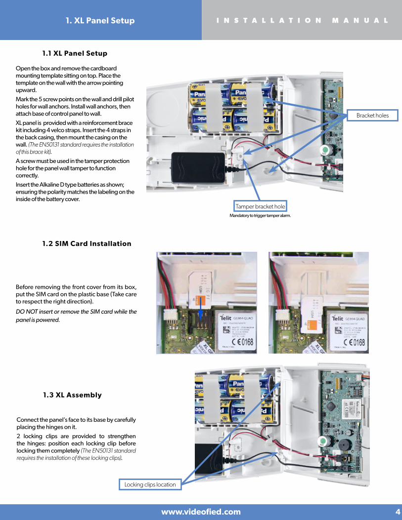
1.1 XL Panel Setup
Open the box and remove the cardboard mounting template sitting on top. Place the template on the wall with the arrow pointing upward.
Mark the 5 screw points on the wall and drill pilot holes for wall anchors. Install wall anchors, then attach base of control panel to wall.
XL panel is provided with a reinforcement brace kit including 4 velco straps. Insert the 4 straps in the back casing, then mount the casing on the wall. (The EN50131 standard requires the installation of this brace kit).
A screw must be used in the tamper protection hole for the panel wall tamper to function correctly.
Insert the Alkaline D type batteries as shown; ensuring the polarity matches the labeling on the inside of the battery cover.
Bracket holes
Before removing the front cover from its box, put the SIM card on the plastic base (Take care to respect the right direction).
DO NOT insert or remove the SIM card while the panel is powered.
1.2 SIM Card Installation
1.3 XL Assembly
Connect the panel’s face to its base by carefully placing the hinges on it.
2 locking clips are provided to strengthen the hinges: position each locking clip before locking them completely (The EN50131 standard requires the installation of these locking clips).
Tamper bracket holeMandatory to trigger tamper alarm.
Locking clips location
www.videofied.com
I N S T A L L A T I O N M A N U A L
4
1. XL Panel Setup

1.4 Powering and Initialization
• The panel is powered by a mains power supply with 4 LR20 alkaline backup batteries (Option 1 recommended) or by 8 LR20 alkaline batteries (Option 2). When the panel is powered, it will beep and the built-in keypad should start flashing.
• Press and hold the PROGRAMMING BUTTON for 10 seconds, until the panel beep again and the panel keypad lights up.
• The panel is now reset, a CMA, XMA or XMB has to be enrolled to configure the panel.
Mains Connector
Programming Button
Batteries connector
Option 1
Option 2
THE CONTROL PANEL MUST BE CONNECTED TO AN EXTERNAL POWER SUPPLY (OPTION 1) WHEN USING THE RINGTONE FEATURE OR SMARTPHONE APP.
To install the power supply inside the box, break the plastic battery separator.
www.videofied.com
I N S T A L L A T I O N M A N U A L
5
1. XL Panel Setup
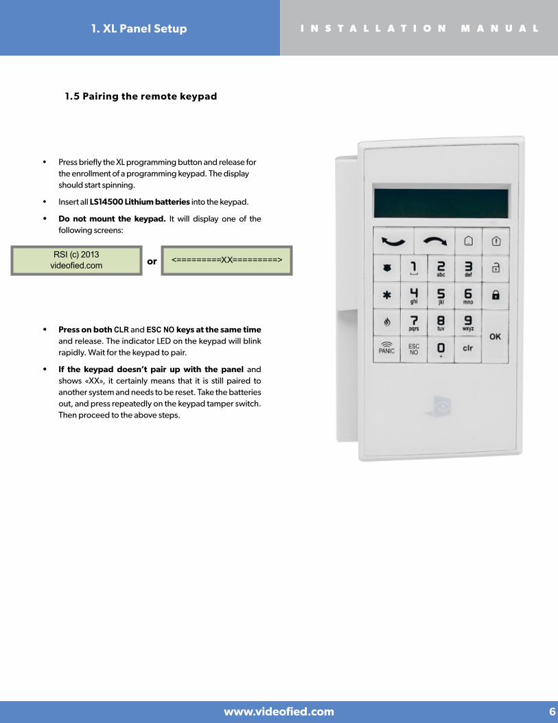
• Press briefly the XL programming button and release for the enrollment of a programming keypad. The display should start spinning.
• Insert all LS14500 Lithium batteries into the keypad.
• Do not mount the keypad. It will display one of the following screens:
1.5 Pairing the remote keypad
RSI (c) 2013videofied.com <=========XX=========>or
• Press on both CLR and ESC NO keys at the same time and release. The indicator LED on the keypad will blink rapidly. Wait for the keypad to pair.
• If the keypad doesn’t pair up with the panel and shows «XX», it certainly means that it is still paired to another system and needs to be reset. Take the batteries out, and press repeatedly on the keypad tamper switch. Then proceed to the above steps.
www.videofied.com
I N S T A L L A T I O N M A N U A L
6
1. XL Panel Setup

Keypad Display Actions and comments
KEYPAD 1RECORDED
RADIO RANGE TEST?
RF TESTx/9
RF TEST9/9
RADIO RANGE TEST?
INSTALLER CODE
4 TO 6 DIGITSTHEN OK/YES
INSTALLER CODE :
< - LANGUAGE : - >ENGLISH (UK)
The system can also be programmed in: french, italian, german, dutch, spanish, swedish, portuguese, danish, czech and polish.
The language can be changed at any time once the panel is programmed in the MAINTENANCE menu.
The Radio Range test must be run during the device learning process in order to ensure proper pairing with the control panel. This test measures the strength of communication between the device and the control panel. The keypad will display a real time radio range value on a scale of 9.
To receive the most accurate results you must run the radio range test for at least 30 seconds.
Result must be 8 out of 9 or better for reliable transmission.
Using the Alphanumeric Keypad, enter the Installer Code of your choice.
The Installer Code will be used for all future maintenance and configuration.
This code is important to keep track of.
There is no back door or Default codes to the system.
Please refer to the restriction rule for codes (Chapter 3.5). Some codes are already used by default and therefore cannot be used.
OK or YES
OK or YES
Please wait
OK or YES
ESCNO
for language selection
OK or YES
CONFIRM CODE
OK or YES
OK or YES
www.videofied.com
I N S T A L L A T I O N M A N U A L
7
2. XL Panel Programming
Keypad display Actions and comments
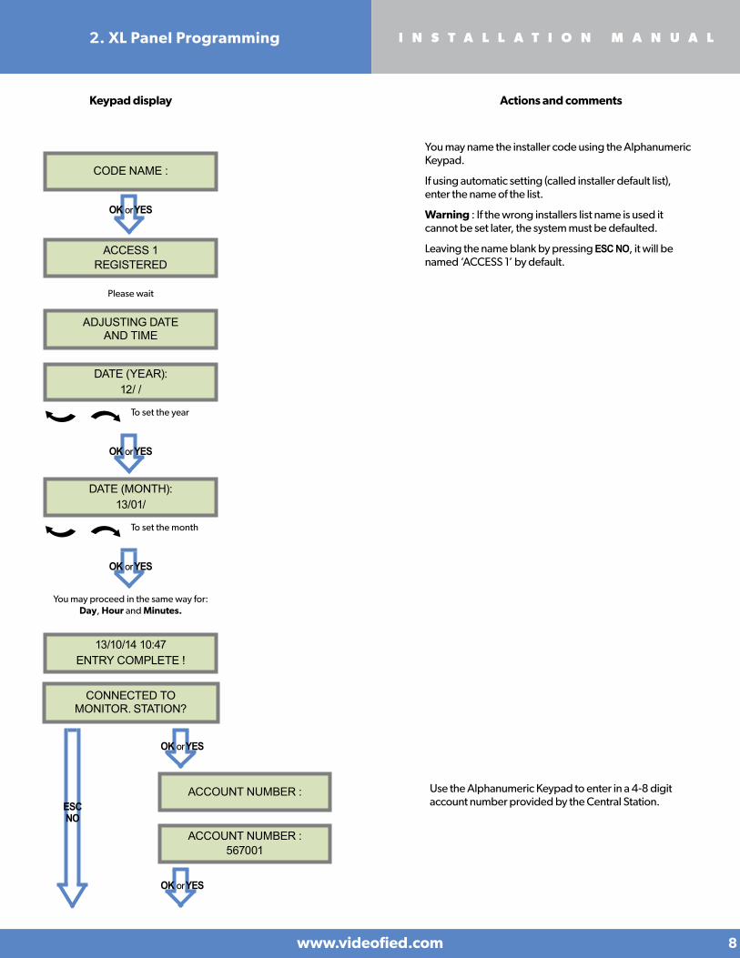
CODE NAME :
OK or YES
ACCESS 1REGISTERED
You may name the installer code using the Alphanumeric Keypad.
If using automatic setting (called installer default list), enter the name of the list.
Warning : If the wrong installers list name is used it cannot be set later, the system must be defaulted.
Leaving the name blank by pressing ESC NO, it will be named ‘ACCESS 1’ by default.
Please wait
ADJUSTING DATE AND TIME
DATE (YEAR):12/ /
To set the year
OK or YES
DATE (MONTH):13/01/
To set the month
OK or YES
You may proceed in the same way for:Day, Hour and Minutes.
13/10/14 10:47ENTRY COMPLETE !
ACCOUNT NUMBER :
CONNECTED TO MONITOR. STATION?
OK or YES
Use the Alphanumeric Keypad to enter in a 4-8 digit account number provided by the Central Station.
ACCOUNT NUMBER :567001
OK or YES
ESCNO
www.videofied.com
I N S T A L L A T I O N M A N U A L
8
2. XL Panel Programming

TEST (hour) :04:
CODE/STATE MODIFICATION?
Test Periodicity: 1 hour, 12 hours, 24 hours, 48 hours, 7 days or no tests.
We suggest a 24 hours periodic test call.
PERIODIC TEST
PERIODE DE TEST : 24 HOURS
To select periodicity
OK or YES
OK or YES
TEST (minutes) :04:15
OK or YES
OK or YES
CODE/STATE MODIFICATION
The CODE/STATE MODIF. menu is to configure the transmitted events to the monitoring station, use the arrow keys to toggle between events and OK or YES to modify.
ALARM: event transmitted upon occurrence.
ALARM/END: event is transmitted on occurrence and on event restoral.
NOT TRANSMITTED: event is not transmitted, however it will appear on the keypad.
Please liaise with your Monitoring Station to ensure that the requested events to transmit are correctly set.
Keypad display Actions and comments
Events list
ESCNO
SERVER ADDRESSES ?
OK or YES
WaitESCNO
www.videofied.com
I N S T A L L A T I O N M A N U A L
9
2. XL Panel Programming

IP1 ADDRESS 0.0.0.0
DOMAIN NAME 1 PORT 1888
SERVERADDRESSES ?
SERVERADDRESSES ?
OK or YES
ESCNO
ESCNO
OK or YES
APN CODEinternet-entrepr
USER NAMEorange
PASSWORDorange
The APN Code (Access Point Name), User Name and Password are supplied by the mobile operator. Please make sure you have entered the code exactly as indicated by your local SIM card operator.
Press OK or YES to enter/modify the parameter then OK or YES for validation.
Note: When entering your SIM card settings, both APN codes, username and password fields are case sensitive! It makes a difference between UPPER and lower case letters.
To switch between UPPER and lower case, use the M/m key from CMA keypad or hold a digit key (0-9) for XMA/XMB.
ESCNO
ESCNO
The IP1 address, Domain name 1 and/or Port 1 are provided by the monitoring station. Leave Port details at 888 unless otherwise instructed.
Press OK or YES to enter/modify the parameter then OK or YES for validation.
WARNING : You will use either an IP address or a Domain name but not both, leave the Domain name blank if an IP address has already been entered.
Press on the right arrow to configure IP/Domain name 2 and PORT2 (for the back-up server), and IP/Domain name TMT and PORT TMT (to configure remote maintenance server).
www.videofied.com
I N S T A L L A T I O N M A N U A L
10
2G3GPARAMETERS?
2G3GPARAMETERS?
2G3G LEVEL ?
2. XL Panel Programming
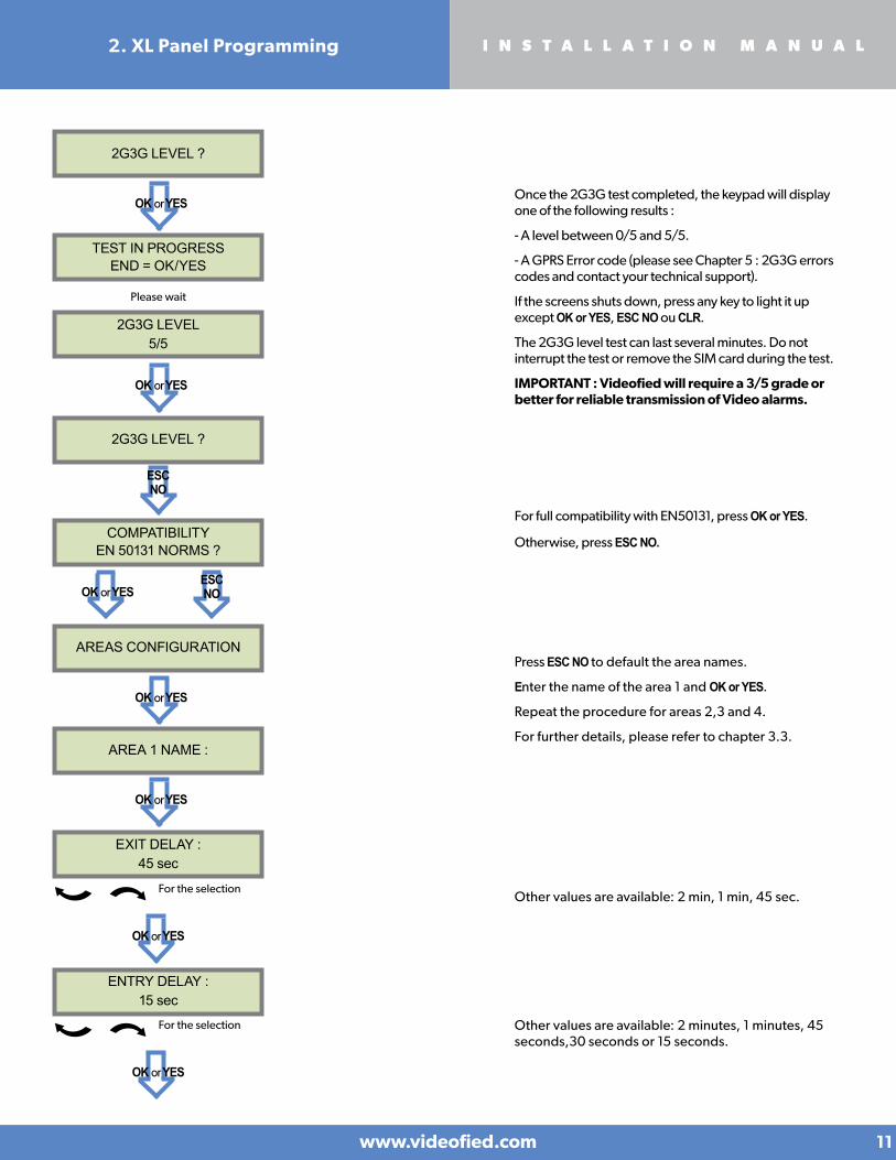
Once the 2G3G test completed, the keypad will display one of the following results :
- A level between 0/5 and 5/5.
- A GPRS Error code (please see Chapter 5 : 2G3G errors codes and contact your technical support).
If the screens shuts down, press any key to light it up except OK or YES, ESC NO ou CLR.
The 2G3G level test can last several minutes. Do not interrupt the test or remove the SIM card during the test.
IMPORTANT : Videofied will require a 3/5 grade or better for reliable transmission of Video alarms.
Please wait
ESCNO
COMPATIBILITYEN 50131 NORMS ?
For full compatibility with EN50131, press OK or YES.
Otherwise, press ESC NO.
ESCNO
AREAS CONFIGURATION
AREA 1 NAME :
Press ESC NO to default the area names.
Enter the name of the area 1 and OK or YES.
Repeat the procedure for areas 2,3 and 4.
For further details, please refer to chapter 3.3.
ENTRY DELAY :15 sec
EXIT DELAY :45 sec
For the selection
OK or YES
For the selection
OK or YES
Other values are available: 2 min, 1 min, 45 sec.
Other values are available: 2 minutes, 1 minutes, 45 seconds,30 seconds or 15 seconds.
www.videofied.com
I N S T A L L A T I O N M A N U A L
11
OK or YES
TEST IN PROGRESSEND = OK/YES
2G3G LEVEL5/5
2G3G LEVEL ?
2G3G LEVEL ?
OK or YES
OK or YES
OK or YES
OK or YES
2. XL Panel Programming
PRESS PROGRAM BUTTON OF DEVICE
RECORDING DEVICES
ENTERING A NEW DEVICE ?
BADGE ENTERED ?
RECORDING A NEW BADGE ?
END OF CONFIGURATION
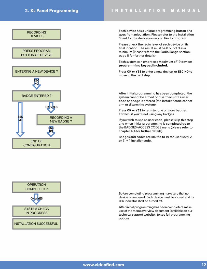
Each device has a unique programming button or a specific manipulation. Please refer to the Installation Sheet for the device you would like to program.
Please check the radio level of each device on its final location. The result must be 8 out of 9 as a minimum (Please refer to the Radio Range section, page 8 for further details).
Each system can embrace a maximum of 19 devices, programming keypad included.
Press OK or YES to enter a new device or ESC NO to move to the next step.
ESCNO
ESCNO
ESCNO
After initial programming has been completed, the system cannot be armed or disarmed until a user code or badge is entered (the installer code cannot arm or disarm the system).
Press OK or YES to register one or more badges. ESC NO if you’re not using any badges.
If you wish to use an user code, please skip this step and when initial programming is completed go to the BADGES/ACCESS CODES menu (please refer to chapter 4.4 for further details).
Badges and codes are limited to 19 for user (level 2 or 3) + 1 installer code.
www.videofied.com
I N S T A L L A T I O N M A N U A L
12
2. XL Panel Programming
OK or YES
OPERATIONCOMPLETED ?
SYSTEM CHECK IN PROGRESS
INSTALLATION SUCCESSFUL !
Before completing programming make sure that no device is tampered. Each device must be closed and its LED indicator shall be turned off.
After initial programming has been completed, make use of the menu overview document (available on our technical support website), to see full programming options.
OK or YES
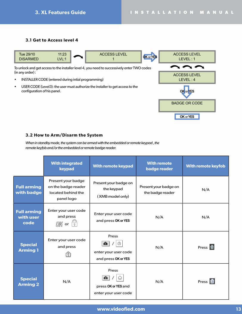
3.2 How to Arm/Disarm the System
When in standby mode, the system can be armed with the embedded or remote keypad , the remote keyfob and/or the embedded or remote badge reader.
With integrated keypad
With remote keypadWith remote
badge readerWith remote keyfob
Full arming with badge
Present your badge
on the badge reader
located behind the
panel logo
Present your badge on
the keypad
( XMB model only)
Present your badge on
the badge reader N/A
Full arming with user
code
Enter your user code
and press
or
Enter your user code
and press OK or YESN/A N/A
Special Arming 1
Enter your user code
and press
Press
/
enter your user code
and press OK or YES
N/A Press
Special Arming 2
N/A
Press
/
press OK or YES and
enter your user code
N/A Press
www.videofied.com
I N S T A L L A T I O N M A N U A L
13
3.1 Get to Access level 4
Tue 29/10 11:23DISARMED LVL:1
ACCESS LEVEL1
ACCESS LEVELLEVEL : 1
ACCESS LEVELLEVEL : 4
OK or YES
OK or YES
To unlock and get access to the installer level 4, you need to successively enter TWO codes (in any order) :
• INSTALLER CODE (entered during intial programming)
• USER CODE (Level3): the user must authorize the installer to get access to the configuration of his panel. OK or YES
BADGE OR CODE
3. XL Features Guide

3.3 Arming and Siren Mode Configuration
• Use to go to menu :
CONFIGURATION (LEVEL 4) > SPECIAL ARMING MODES > FULL ARM, SP1 or SP2
Use direction arrows to select the arming mode you want to modify and OK / YES.
• There is 3 different arming modes :
FULL ARM : Arming of all areas and all devices. Use a badge or a user code and press / on the panel keypad, OK / on
the XMA/XMB keypad or the YES key on the CMA keypad.
SP1 : Partial Arming (1) is enabled by entering the user code and pressing on the panel keypad, on the XMA/XMB keypad,
the key on the CMA keypad or on the remote keyfob RC.
SP2 : Partial Arming (2) is unavailable on the XL panel keypad. It is enabled by pressing the key on a XMA/XMB keypad
on a CMA keypad, or on the remote keyfob RC.
Wake the integrated keypad by placing your palms over it.
Enter the pairing mode by pressing the key for 3 seconds, the numerical touchpad will blink
then enter 000000 and press the display will start spinning, confirming that you entered
the programming mode.
Install the batteries in the CMA or XMA keypad. Simultaneously press and release the CLR and
ESC NO buttons on the keypad. The red LED indicator light will blink rapidly, then twice slowly.
The keypad display will change to KEYPAD 1 RECORDED. Press OK / YES to acknowledge this,
then type the installer code for the system followed then press OK / YES again.
This keypad learning procedure is only used when connecting a CMA or XMA keypad to the
XL control panel after initial programming.
3.4 Pairing a new keypad without opening the panel
KEYPAD 1 RECORDED
INSTALLER CODE
Enter the installer code and : OK or YES
OK or YES
For each arming mode, it is possible to specify how each of the 4 areas will be armed and how the system will behave during an alarm.
Areas : 1 2 3 4 Each time you press the corresponding number, the system will toggle the arming state for the respective area.
State : A A A A Press OK / YES after this configuration step. The system will then display what siren mode will be in effect for this special profile. Select the siren mode using the direction arrows then press OK / YES .
A Armed
D Disarmed
PPerimeter
(by default : all opening contacts*)
EExternal
(by default : all opening contacts with external access*)
* You can set your devices as : External, Perimeter, ou External +Perimeter. Please go to the menu:
CONFIGURATION (LVL 4) > AREAS AND DEVICES > DEVICES > DEVICES CONFIGURATION > DEVICE TYPE
Siren Immediate triggering of all sirens
Delay Beeps Entry/Exit delay beeps, then triggering of all sirens
Silent No Sirens, No Beeps
Without Siren Beeps on the keypad only
www.videofied.com
I N S T A L L A T I O N M A N U A L
14
3. XL Features Guide
www.videofied.com
I N S T A L L A T I O N M A N U A L
15
3. XL Features Guide
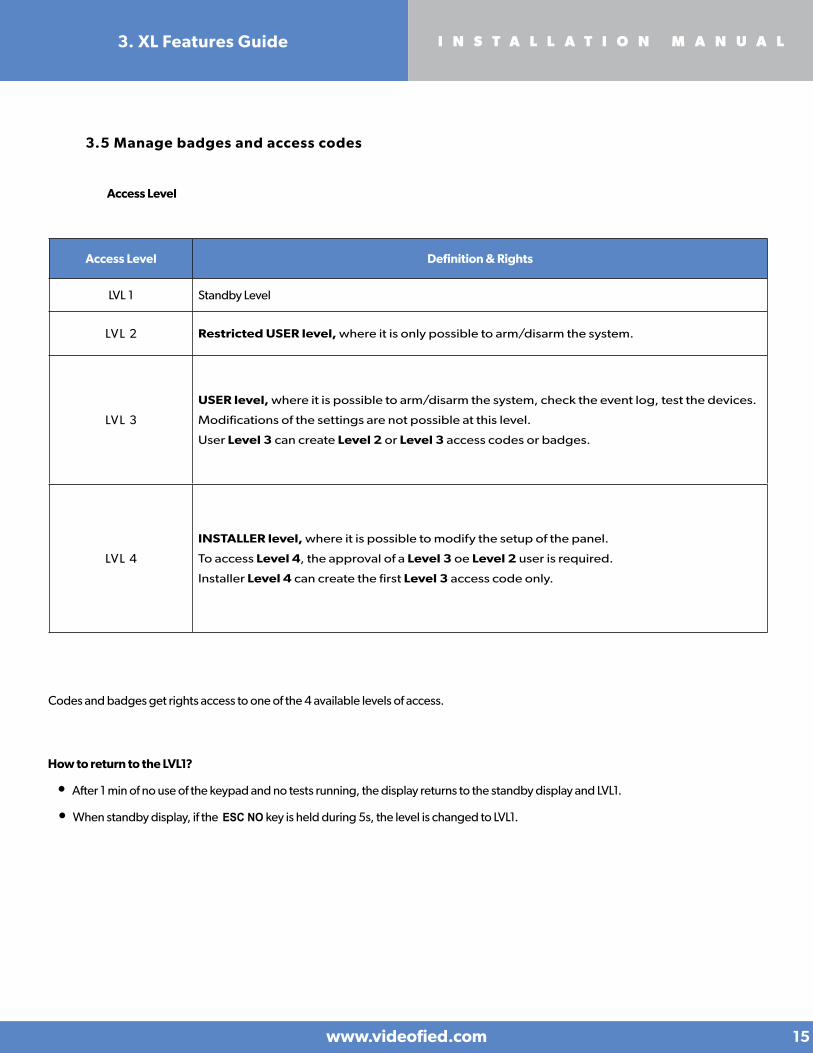
3.5 Manage badges and access codes
Codes and badges get rights access to one of the 4 available levels of access.
Access Level Definition & Rights
LVL 1 Standby Level
LVL 2 Restricted USER level, where it is only possible to arm/disarm the system.
LVL 3
USER level, where it is possible to arm/disarm the system, check the event log, test the devices.
Modifications of the settings are not possible at this level.
User Level 3 can create Level 2 or Level 3 access codes or badges.
LVL 4
INSTALLER level, where it is possible to modify the setup of the panel.
To access Level 4, the approval of a Level 3 oe Level 2 user is required.
Installer Level 4 can create the first Level 3 access code only.
How to return to the LVL1?
• After 1 min of no use of the keypad and no tests running, the display returns to the standby display and LVL1.
• When standby display, if the ESC NO key is held during 5s, the level is changed to LVL1.
Access Level

www.videofied.com
I N S T A L L A T I O N M A N U A L
16
3. XL Features Guide
Enter a new end user Badge/Code Delete an end user Badge/Code
ENTER A BADGE/CODE
Press twice on the right arrow
DELETING BADGES/CODES
Badges/codes list
Select badge/code then
OK or YES
DELETING CODEACCESS 5
CODEDELETED
BADGE OR CODE
CODE NAME :
CONFIRM THE CODE
ACCESS 2 ENTRY COMPLETE
BADGESACCESS CODES
ENTER A BADGE/CODE
Enter a 4-6 digit user code and
OK or YES
or present a badge in front of the reader until you hear the registration beep.
OK or YES
OK or YES
OK or YES
OK or YES OK or YES
OK or YES
When a code is created (1000 for example), the 2 next codes and previous codes (0998, 0999, 1001 and 1002) will be automatically reserved.
The +1 code (1001) is used for disarming under duress.
The +2 code (1002) is used for panic.
The -1 and -2 codes (0998 et 0999) are reserved to prevent conflicts when creating a new user code.
Reserved Codes
000000
From 9998 to 9999
From 99998 to 99999
From 999898 to 999999
From 314157 to 314159
All user codes +1
All user codes +2
All user codes -1
All user codes -2
Reserved Codes
Up to 19 codes (or badges) can be registered into the panel with the engineer code.
A code has 4 to 6 digits (0 to 9).
The table presents the reserved code possibilities that cannot be used.
Those codes are used for maintenance or as panic/duress codes.
A total of 186 codes are forbidden.

3..6 Delete the keypad or any other device
www.videofied.com
I N S T A L L A T I O N M A N U A L
17
3. XL Features Guide
You can now remove the batteries from the device
ACCESS LEVEL4 CONFIGURATION
GENERALPARAMETERS
OK or YES
to select the device and press
OK or YES
< = = = = XX = = = = >
DELETE
AREAS ANDDEVICES
DEVICES
ADD A NEWDEVICE
DEVICECONFIGURATION
A1 : KEYPADKEYPAD 1
OK or YES
OK or YES
OK or YES
Devices list
OK or YES
OK or YES

www.videofied.com
I N S T A L L A T I O N M A N U A L
18
3. XL Features Guide
Unscrew the locking screw on the left-hand side of the panel, using a paper clip push through the opening hole to open the
panel’s cover.
When user disarms the system, the XL or
keypad indicates the last event. Refer to
chapter 6 to know the meaning of each
symbol.
In case of the user needs to read the full log
file, use the keypad to go in EVENT LOG,
press OK or YES on SELECT LAST EVENTS
and use arrow to list the events.
3.7 Read the event log
3.8 Opening the cover of an installed panel
1 Area 1 is always delayed. When you register a keypad or a badge
reader into an area, that area will automatically be delayed.
2 Never position a panel next to a high voltage electrical cabinet .
3 Press CLR to erase a typing mistake.
4 Never register the same device twice (delete from the system first).
5 Registration of up to 19 devices (including the keypad).
6 Respect indoor infrared devices installation height (2m10 to 2m30).
7 Outdoor cameras have to be installed at 2m60 to 3 meters
height. Those devices need to to protect an access and not a zone.
8 Do not fix the keypad at the beginning of the installation as it will
need to be portable during programming.
Always clean the lens of the cameras after the installation
(Use a clean, dry cloth, taking care not to exert pressure on
the lens).
9
10 To switch between UPPER and lower case, use the M/m
key from the CMA keypad or hold a digit key (0 to 9) for
XMA/XMB.
11 Internal components are fragile, be careful opening or
closing the panel.
LCD screen goes dark after 30 seconds of inactivity, press an
arrow or numeric key to light it up.
13 Use only batteries provided by Videofied (siren : Alkaline
batteries).
14 Infrared detectors should never be installed in stairs or close
to stairs (false alarm risks).
15 A colon display [:] means that the parameter can be
changed.
12
3.9 Golden Rules
Press OK or YES for more information about an event
EVENTLOG
SELECT LAST EVENTS
OK or YES
15/10/13 11:29MODIFIED PARAMET
OK or YES
15/10/13 11:10SYSTEM DISARMED

www.videofied.com
I N S T A L L A T I O N M A N U A L
19
How to modify the transmission state
• At initial programming, right after the PERIODIC TEST CALL step:
• After initial programming, using a remote keypad :
Example :
If the monitoring station system is set to receive arms and disarms, the ARM / DISARM parameter must be
changed from NOT TRANSMITTED to ALARM / END.
Press OK or YES to access EVENT TRANS. MODIFICATION menu.
The XL panel can be configured to enable or disable the transmission of
events like alarms or defaults.
The installer can modify the default sending settings for those
events, although it will end the EN50131 standard compliance.
CODE/STATE MODIFICATION
4. Transmitted Events List
Use the arrows to access :
CONFIGURATION (level 4) > CONFIGURATION MONITOR. STATION > MONITORING PARAMETERS > EVENT TRANS. MODIFICATION
Then use the arrows to determine the event to modify. Press OK or YES to edit.
These are the default transmitted events :
DEVICE (intrusions) ALERT (Panic Buttons)PANEL LOW BATT.TAMPERDEVICE LOW BATT.PERIODIC TESTDURESS CODEFIREMEDICAL ASSIST.ETHERNET CABLE AC POWER LOSS (AC Power supply)
The following events are not sent by default :
PANEL RESET
PHONELINE FAULT
RADIO JAMMING
SUPERVISION
5 WRONG CODES
ALARM CANCEL
ARM/DISARM (On/Off)
ZONE BYPASS (bypass function enabling/dsiabling)
SWINGER SHUTDOWN
There is 3 different transmission states :
ALARM : event transmitted upon occurrence
ALARM/END : event is transmitted on occurrence and on event restoral
NOT TRANSMITTED : event is not transmitted, however it will appear on the keypad.
www.videofied.com
I N S T A L L A T I O N M A N U A L
20
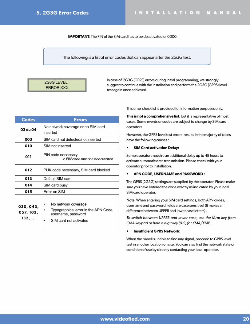
5. 2G3G Error Codes
2G3G LEVEL :ERROR XXX
In case of 2G3G (GPRS) errors during initial programming, we strongly suggest to continue with the installation and perform the 2G3G (GPRS) level test again once achieved.
The following is a list of error codes that can appear after the 2G3G test.
IMPORTANT: The PIN of the SIM card has to be deactivated or 0000.
Codes Errors
03 ou 04LPNo network coverage or no SIM card inserted
003 SIM card not detected/not inserted010 SIM not inserted
011 PIN code necessary -> PIN code must be deactivated
012 PUK code necessary, SIM card blocked
013 Default SIM card
014 SIM card busy015 Error on SIM
030, 043,
057, 102,
132, ...
• No network coverage • Typographical error in the APN Code,
username, password
• SIM card not activated
This error checklist is provided for information purposes only.
This is not a comprehensive list, but it is representative of most cases. Some events or codes are subject to change by SIM card operators.
However, the GPRS level test errors results in the majority of cases have the following causes :
• SIM Card activation Delay:
Some operators require an additional delay up to 48 hours to activate automatic data transmission. Please check with your operator prior to installation.
• APN CODE, USERNAME and PASSWORD :
The GPRS (2G3G) settings are supplied by the operator. Please make sure you have entered the code exactly as indicated by your local SIM card operator.
Note: When entering your SIM card settings, both APN codes, username and password fields are case sensitive! (It makes a difference between UPPER and lower case letters) .
To switch between UPPER and lower case, use the M/m key from CMA keypad or hold a digit key (0-9) for XMA/XMB.
• Insufficient GPRS Network:
When the panel is unable to find any signal, proceed to GPRS level test in another location on site. You can also find the network state or condition of use by directly contacting your local operator.
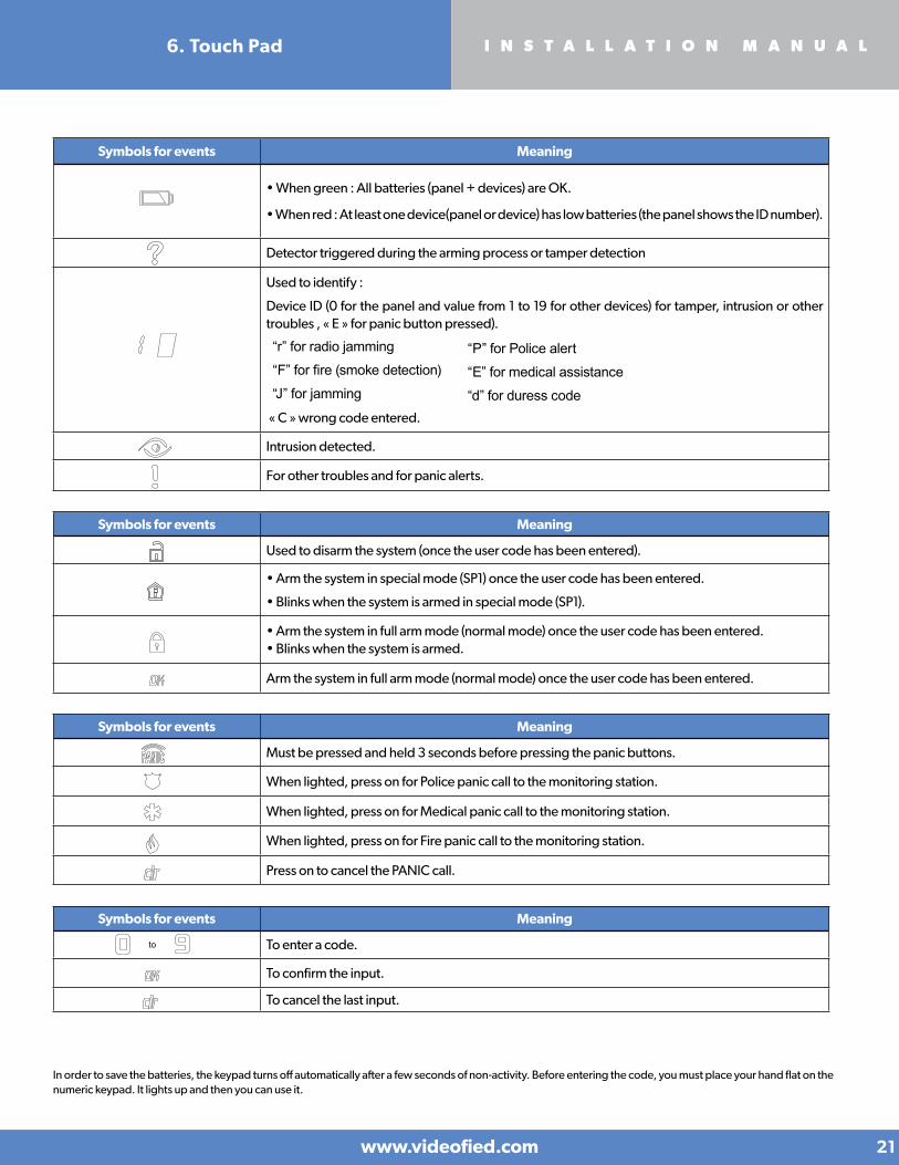
Symbols for events Meaning
D • When green : All batteries (panel + devices) are OK.
• When red : At least one device(panel or device) has low batteries (the panel shows the ID number).
P Detector triggered during the arming process or tamper detection
Used to identify :
Device ID (0 for the panel and value from 1 to 19 for other devices) for tamper, intrusion or other troubles , « E » for panic button pressed).
« C » wrong code entered.
Intrusion detected.
For other troubles and for panic alerts.
Symbols for events Meaning
D Used to disarm the system (once the user code has been entered).
P• Arm the system in special mode (SP1) once the user code has been entered.
• Blinks when the system is armed in special mode (SP1).
• Arm the system in full arm mode (normal mode) once the user code has been entered. • Blinks when the system is armed.
Arm the system in full arm mode (normal mode) once the user code has been entered.
Symbols for events Meaning
D Must be pressed and held 3 seconds before pressing the panic buttons.
P When lighted, press on for Police panic call to the monitoring station.
When lighted, press on for Medical panic call to the monitoring station.
When lighted, press on for Fire panic call to the monitoring station.
Press on to cancel the PANIC call.
Symbols for events Meaning
to D To enter a code.
P To confirm the input.
To cancel the last input.
In order to save the batteries, the keypad turns off automatically after a few seconds of non-activity. Before entering the code, you must place your hand flat on the numeric keypad. It lights up and then you can use it.
“r” for radio jamming
“F” for fire (smoke detection)
“J” for jamming
“P” for Police alert
“E” for medical assistance
“d” for duress code
www.videofied.com
I N S T A L L A T I O N M A N U A L
21
6. Touch Pad

North American Headquarters1375 Willow Lake Blvd, Suite 103Vadnais Heights, MN 55110USAE-Mail : [email protected]
EMEA SALES23, avenue du Général Leclerc92340 BOURG-LA-REINEFRANCEE-Mail : [email protected]
www.videofied.com 22
I N S T A L L A T I O N M A N U A L7. Technical Specifications and Security Notes
Operating FrequencyRequired Voltage
Powering
Current consumptionOperating temperatureMaximum relative humidityDimensions (LxWxD)Weight Approvals
Embedded
868/915/920 MHz Nominal voltage = 6 VLow battery limit = 4.2 V Type B : 1 external power supply with battery backup 4x 1.5 Alkaline D cells (Option 1)orType C: 8x 1,5 V D Alkaline batteries (Option 2)
Standby (1h average) = 420 μA ; Max = 1,3 A -10° / +40° C (-14° /+104° F) 75%, without condensing225 mm x 180 mm x 55 mm (9 in. x 7 in. x 2-1/6 in) 520 g (without batteries)
EN50131-1: 2006; + A1: 2009 Grade 2 - Class IIThe panel must be used with a EN50131-3 certified keypad (CMA, XMA or XMB)EN50131-3: 2009 Grade 2 - ACE Type BEN50131-4: 2009 Grade 2 - Siren type WEN50131-5-3: 2005; + A1: 2009 Grade 2 EN50131-6: 2008 Grade 2 - Type CEN50130-4: 1995; + A1: 1998; + A2: 2003EN50130-5: 1998 Class II
• Touchpad - Minimum number of variations PIN = 1109814 - Number of forbidden PIN codes = 186 (See page 16) - Number of invalid passcode entries before disabling = 5 - Waiting for input code = 60 s - Blocking time after 5 attempts invalid = 90 s - Battery life support memory = nd (Using flash memory)• Badge Reader - ISO/IEC 14443A• Siren - 15 min maximum duration - Indoor use only - Can be self-powered - 105 dB (A) at 1 meter
Security notes / (FR) Notes de sécurité / (DE) Hinweise zur SicherheitFrançais
• Retirez les piles avant toute opération de maintenance !
• Attention ! Il y a un risque d'explosion si l'une des piles utilisées est remplacée par une pile de type incorrect !
• Respectez la polarité lors de la mise en place des piles !
• Ne jetez pas les piles usagées ! Ramenez-les à votre installateur ou à un point de collecte spécialisé.
English• Remove battery before any
maintenance !• WARNING, there is a risk of explosion
if a battery is replaced by an incorrect type!
• Observe polarity when setting up the batteries!
• Do not throw used batteries! Bring them to your installer or a collection point.
Deutsch• Batterien vor jeglichen Wartungsarbeiten
entfernen!• Vorsicht, es besteht Explosionsgefahr,
wenn eine Batterie durch eine Batterie falschen Typs ersetzt wird!
• Achten Sie beim Einsetzen der Batterien auf die Polung!
• Entsorgen Sie Batterien nicht im normalen Haushaltsmüll! Bringen Sie Ihre verbrauchten Batterien zu den öffentlichen Sammelstellen.


![startery.bystartery.by/images/Peugeot.pdf · . 537 V A V kW PASSENGER CARS AO Astra H 1.4 [Z14XEL] 04.04- 10.04 CA1747IR 14 70 04.04- 10.04 CS519 12 1.0 04.04- 10.04 CA1748IR 14 100](https://static.fdocuments.in/doc/165x107/5b158d347f8b9a382f8cd1e5/-537-v-a-v-kw-passenger-cars-ao-astra-h-14-z14xel-0404-1004-ca1747ir.jpg)