en-metalwork-machine-elements-instruction-material.pdf (pdf, 2.61 ...
234
Machine Elements Instruction Material - Fits, Bolt & Screw, Shaft & Hub, Coupling, Belt Drive, Gears, Bearings, Gear Box
Transcript of en-metalwork-machine-elements-instruction-material.pdf (pdf, 2.61 ...

Machine Elements Instruction Material − Fits, Bolt & Screw, Shaft &Hub, Coupling, Belt Drive, Gears, Bearings, Gear Box


Table of ContentsMachine Elements Instruction Material − Fits, Bolt & Screw, Shaft & Hub, Coupling, Belt Drive, Gears, Bearings, Gear Box..............................................................................................................................1
Introduction.............................................................................................................................................1Hints for the teacher...............................................................................................................................11. Fit........................................................................................................................................................2
Information sheet.............................................................................................................................2Task sheet......................................................................................................................................12
2. Bolt and screw connections..............................................................................................................20Objectives......................................................................................................................................20Information sheet...........................................................................................................................21Task sheet......................................................................................................................................36Solutions........................................................................................................................................49
3. Shaft−hub connections.....................................................................................................................63List of objectives.............................................................................................................................63Information sheet...........................................................................................................................64Task sheet......................................................................................................................................74Solutions........................................................................................................................................80
4. Couplings and Clutches....................................................................................................................91List of Objectives............................................................................................................................91Information sheet...........................................................................................................................92Task sheet....................................................................................................................................101Solutions......................................................................................................................................108
5. Belt drive.........................................................................................................................................119List of objectives...........................................................................................................................119Information sheet.........................................................................................................................120Task sheet....................................................................................................................................127Solutions......................................................................................................................................132
6. Gears..............................................................................................................................................137List of objectives...........................................................................................................................137Information sheet.........................................................................................................................138Task sheet....................................................................................................................................153Solution sheet..............................................................................................................................160
7. Roller bearings................................................................................................................................175Objectives....................................................................................................................................175Information sheet.........................................................................................................................176Activity sheet................................................................................................................................190Task sheet....................................................................................................................................193Solutions......................................................................................................................................201
8. Gear Box.........................................................................................................................................212Objectives....................................................................................................................................212
i

ii

Machine Elements Instruction Material − Fits, Bolt & Screw, Shaft &Hub, Coupling, Belt Drive, Gears, Bearings, Gear Box
Lehr− und Lernmittel,Informationen, Beratung
Educational AidsLiterature, Consulting
Moyens didactiques,Informations, Service−conseil
Material didáctico,Informaciones, Asesoría
Feedback: TGTAC Thailand
Deutsche Gesellschaft fürTechnische Zusammenarbeit (GTZ) GmbH
Introduction
• This Instructional material is developed by experienced specialists of the Thai−German Teaching AidCentre. It can be used with a minimum of preparation.
• Selecting the objectives, we concentrated on the most important ones. An industrial survey helped us infinding them.
• If the teacher thinks that an objective is less important, he can teach this objective less intensively.
• The teaching method, which should be used, is the "questioning technique" Please do not only lecture.
Hints for the teacher
There are 6 parts for each topic:
1

1. List of objectives2. Information sheets3. Task sheets4. Activity sheets5. Teaching aids (transparencies, models, etc.)6. Solutions
1. A list of objectives shows the teacher what the student should know after the lesson.
2. Information sheets show pictures with a short explanation of the subject matter. These information sheetsshould be given to the student after the lesson as a summary.
3. Task sheets help the teacher to check the learning progress. They should be used at the end of one period.It is necessary to discuss the solutions with the students. Please do not use them as a test,
4. Activity sheets are offered for particular objectives only. Based on information already taught before thestudent should find new information by themselves. Only after the student failed to find the intended solutionby themselves, the teacher will explain it in the normal manner.
5. Teaching aids make the subject matter better understandable and motivate the students.
6. Solutions for the task and activity sheets.
1. Fit
Information sheet
1. Purpose of fit
When producing workpieces, it is impossible to make them all in the same size. As they must beinterchangeable (e.g. spare parts), a system of fit is needed.
2. Basic principle
2

2.1 Tolerance system
− nominal size is the dimension specified in the drawing (e.g. 20 mm)− allowance below nominal size is the distance between zero line and minimum sizedworkpiece.− allowance above nominal size is the distance between zero line and maximum sizedworkpiece.− tolerance is the difference between minimum and maximum sized workpiece.− actual size is the real size of the workpiece,− zero line is the line which indicates the nominal size.
2.2 Specification of tolerance range
2.2.1 of a shaft (specified by small letters)
3

2.2.2 of a bore (specified by big letters)
4

2.3 Accuracy level of tolerance
The tolerance value is related to the nominal size of a workpiece, it increases with the nominal size.
The tolerance system is divided into 20 quality grades:
01 − 5 is used for high precision such as production of measuring instruments6 − 11 is used for machine parts12 − 18 is used for low precision such as casting and welding
ISO basic standard, tolerance in 1 mm DIN 7151 (11.64)
nominal sizefrom.. to
IT
01 0 1 2 3 4 5 6 7 8 9 10 11 12 13 14 15 16 17 18
mm 1..3 0,3 0,5 0,8 1,2 2 3 1 6 10 14 23 40 60 100 140 250 400 600 − −
3..6 0,4 0,6 1 1,5 2,5 4 5 8 12 18 30 48 75 120 180 300 480 750 − −
6..10 0,4 0,6 1 1,5 2,5 4 6 9 15 22 36 58 90 150 220 360 580 900 1500 −
10..18 0,5 0,8 1,2 2 3 5 8 11 18 27 43 70 110 180 270 430 700 1100 1800 2700
18..30 0,6 1 1,5 2,5 4 6 9 13 21 33 52 84 130 210 330 520 840 1300 2100 3300
30..50 0,6 1 1,5 2,5 4 7 11 16 25 39 62 100 160 250 360 620 1000 1600 2500 3900
30..80 0,8 1,2 2 3 3 8 13 19 30 46 74 120 190 300 460 740 1200 1900 3000 4600
80..120 1 1,5 2,5 4 6 10 15 22 35 54 87 140 220 350 340 870 1400 2200 3500 5400
120..180 1,2 2 3,5 5 8 12 18 25 40 63 100 160 250 400 630 1000 1600 2500 4000 6300
180..250 2 3 4,3 7 10 14 20 29 46 72 115 185 290 460 720 1150 1850 2900 4600 7200
250..315 2,5 4 6 8 12 16 23 32 52 81 130 210 320 520 810 1300 2100 3200 5200 8100
315..400 3 5 7 9 13 18 23 36 57 89 140 230 360 570 890 1400 2300 3600 5700 8900
400..500 4 6 8 10 15 20 27 40 63 97 155 250 400 630 970 1350 2500 4000 6300 9700
ISO − Tolerance−series, Quality grade (5)
5

Example: If the nominal size is 20 mm and we choose quality grade 6, we will get a toleranceof 13 mm (= 0.013 mm)
2.4 Inscription of tolerance on drawings
bore shaft fitting
Note: A bore tolerance is defined by a big letter and must be located in the right corner abovethe nominal size. For shaft tolerance small letter are used.
3. Type of fit
3.1 clearance fit
3.2 transit fit
6
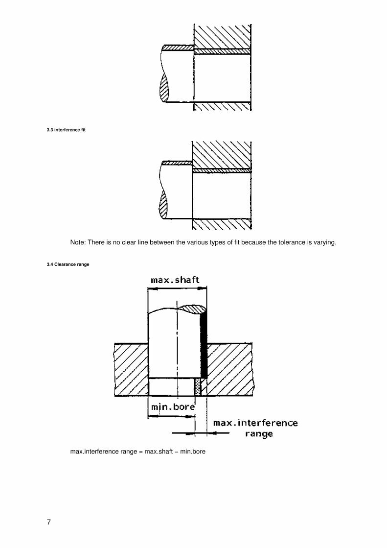
3.3 interference fit
Note: There is no clear line between the various types of fit because the tolerance is varying.
3.4 Clearance range
max.interference range = max.shaft − min.bore
7

min.interference range = min.shaft − max.bore
max.clearance range = max.bore − min.shaft
8

min.clearance range = min.bore − max.shaft
4. Fit systems
In order to lown production costs the number of possible pairs is limited by using two fit systems:
4.1 Hole basis fit system
is used in mechanical engineering, machine tools and cars because it is easier to produce different exactshaft diameters than to produce different exact hole diameters.
9

4.2 Shaft basis fit system
is used in textile and agriculture machinery because long shafts with constant diameters which are provided inh6, h7, h8.... by the steel mills are used.
4.3 Examples
10

4.4 Free tolerance
is used with work without assembling such as welding, casting, rolling, etc.
Standard table of free tolerance:
11

dimension inmm
accuracy
0.5 to3
3 to6
3 to30
30 to120
120to
315
315to
1000
1000to
2000
2000to
4000
4000to
3000
8000to
12000
12000to
16000
16000to
20000
precise ±0.05 ±0.05 ±0.1 ±0.15 ±0.2 ±0.5 ±0.5 ±0.8 − − − −
medium ±0.1 ±0.1 ±0.2 ±0.3 ±0.5 ±0.8 ±1.2 ±2 ±3 ±4 ±5 ±6
rough − ±0.2 ±0.5 ±0.8 ±1.2 ±2 ±3 ±4 ±5 ±8 ±7 ±8
very rough − ±0.5 ±1 ±1.5 ±2 ±3 ±4 ±6 ±8 ±10 ±12 ±12
Example: A shaft with 60 and medium accuracy will have a tolerance of ± 0,3.
5. Application
Type of fit Fitting character Example Borebasis
Holebasis
interference When high pressure is needed shaft−hub connection by shrink fit H7 − z8H7 − x7
Z8 −h6X7 −h6
When medium pressure isneeded
bush in housing H7 − s6H7 − r6
S6 −h6R7 −h6
transition To assemble must be hit hardwith a hammer.
hub which is fixed on the shaft againstaxial movement by fit
H7 − m6 M7 −h6
To assemble must be hit witha hammer
normal shaft−hub connection H7 − k6 K7 −h6
To assemble must be hit softwith a hammer
hub must slide oh the shaft during work H7 − j6 J7 −h6
clearance must have some clearance bush bearing with shaft H7 − f7 F7 −h6
big clearance screw in a hole H11 −c11H11 −a11
C11 −h11A11 −h11
Note: For more details have a look in the table book
Task sheet
1. A fit system is used: to minimise toleranceto make spare parts interchargeableto make the workpieces more precisely
2.1 Complete the drawing with the following terms:
nominal, actual, min. and max. size, allowance above and below nominal size tolerance, zeroline
12

2.2
a) The position of tolerance range of a shaft is specified with big/small lettersb) The letter a Indicates that the tolerance range is under/above the zero linec) Which tolerance ranges are touching the zero line?
2.3
a) The level of accuracy is indicated by __________ from _______ to ________ and it depends on _______of workpiece _______
b) The accuracy level used for machine parts is normally _______ to _______
c) A high accuracy level is indicated by _______, a low accuracy level is indicated by _______
2.4
a) Which tolerance inscription is correct?
b) Which tolerance inscription is correct?
3.1
a)There are 3 types of fit, they are: __________b)When the shaft is always bigger than the bore, the type of fit is on __________
3.2 The min. clearance range is given by min. bore − min./max. bore
4.
a) A fit system in which the shaft is adjusted to the bore is called it is used with __________
b) For a shaft basis fit system the letter f/h/n will be used.
13
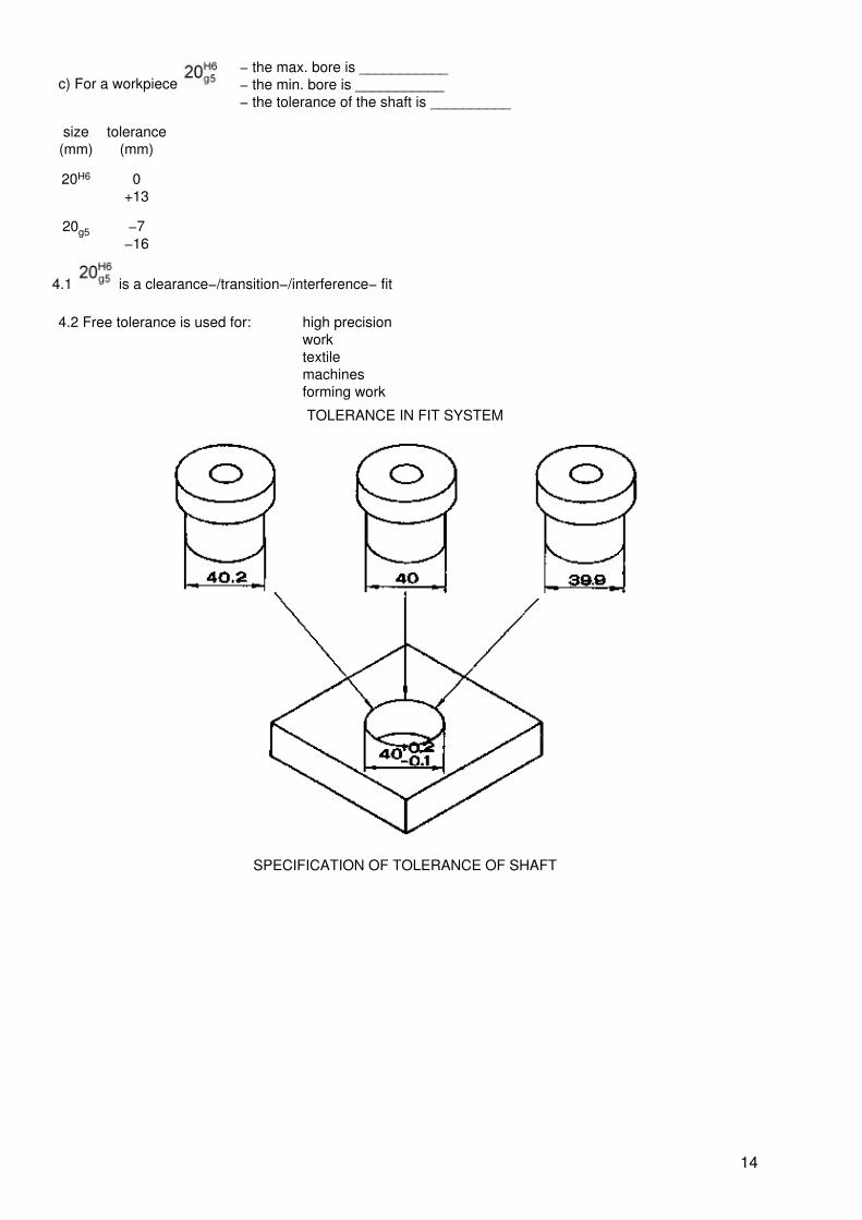
c) For a workpiece − the max. bore is ___________− the min. bore is ___________− the tolerance of the shaft is __________
size(mm)
tolerance(mm)
20H6 0+13
20g5 −7−16
4.1 is a clearance−/transition−/interference− fit
4.2 Free tolerance is used for: high precisionworktextilemachinesforming work
TOLERANCE IN FIT SYSTEM
SPECIFICATION OF TOLERANCE OF SHAFT
14

FREE TOLERANCE
dimension in mm.
accuracy 0.5 3 6 30 120 315 1000 2000 4000 8000 12000 16000
3 6 30 120 315 1000 2000 4000 8000 12000 16000 20000
precise ± 0.05 ± 0.05 ± 0.1 ± 0.15 ± 0.2 ± 0.3 ± 0.5 ± 0.8 − − − −
medium ± 0.1 ± 0.1 ± 0.2 ± 0.3 ± 0.5 ± 0.8 ± 1.2 ± 2 ± 3 ± 4 ± 5 ± 6
rough − ± 0.2 ± 0.5 ± 0.8 ± 1.2 ± 2 ± 3 ± 4 ± 5 ± 6 ± 7 ± 8
very rough − ± 0.5 ± 1 ± 1.5 ± 2 ± 3 ± 4 ± 6 ± 8 ± 10 ± 12 ± 12
TOLERANCE SYSTEM
15

ACCURACY GRADE OF TOLERANCE
IT
size 01 0 1 2 3 4 5 6 7 8 9 10 11 12 13 14 15 16 17 18
1..3 0.3 0.5 0.8 1.2 2 3 4 6 10 14 25 40 60 100 140 250 400 600 − −
3..6 0.4 0.6 1 1.5 2.5 4 5 8 12 18 30 48 75 120 180 300 480 750 − −
6..10 0.4 0.6 1 1.5 2.5 4 6 9 15 22 36 58 90 150 220 360 580 900 1500 −
10..18 0.5 0.8 1.2 2 3 5 8 11 18 27 43 70 110 150 270 430 700 1100 1800 2700
16

TYPE OF FIT
17

Clearance fit Transit fit Interference fit
SPECIFICATION OF TOLERANCE RANGE OF BORE
INSCRIPTION OF TOLERANCE AN DRAWING
ADVANTAGE AND DISADVANTAGE OF FIT IN BORE BASIS SYSTEM AND SHAFT BASIS SYSTEM
Advantage Disadvantage
18

bore basis system
− the shaft can be easily adjustedto the housing− cheap tools will be used
− the shaft size varies
shaft basis system
− the shaft size will be constant − the housing can hardly beadjusted to the shaft− expensive tools will be used
CLEARANCE RANGE INTERFERENCE RANGE
Bore basis fit system
19

Shaft basis fit system
2. Bolt and screw connections
Objectives
The student should be able to
1. explain the difference between permanent and detachable joint2. understand the effect of the internal forces in a cross loaded connection3. understand the effect of the internal forces in an axial loaded connection4. differentiate between screw, bolt and stud5. describe the use of a fitting bolt6. name 7 types of screws and describe a typical application7. name 8 types of nuts and describe a typical application8. attach 5 screws (bolts) to this application9. explain the meaning of the screw code10. explain why the washer is placed under the nut rather than under the bolt head11. differentiate between form fitting and friction lock
20

12. choose the right tool for 6 different screws (nuts)13. explain the effect of rust or oil in a bolt thread to the clamping force14. explain the advantage of a torque wrench15. choose the right sequence of tightening nuts (screws)16. find out the reason for typical bolt defects17. describe 2 methods to extract broken screws18. describe 2 methods to repair internal threads19. explain why bolt connections of new machines must be retightened after some servicetime
Information sheet
1. Purpose and basic function
1.1 Permanent joint−detachable joint
1.1.1 Permanent joint
The joint is destroyed when loosened.
1.1.2 Detachable joint
The joint is not destroyed when loosened.
1.2 Internal forces in a bolt joint
1.2.1 Clamping force and load in axial direction
21

1.2.2 Preload force and cross load
F2·µ > F3
(µ = coefficient of friction)
F2·µ < F3
Clamping force to low
− sufficient clamping force, but oily or dirtysurface
2. Types and main design
2.1 Screw, bolt and stud
Type Application
Figure1. Screw
− is used in threadedholes
Figure2. Bolt = Screw = Nut
− is used with throughholes
22

Figure3. Stud
− is used when thejoint is separatedfrequently.
2.2 Fitting Bolt
FigureBolt
FigureWorkpiece are not centered Figure
Workpiece is centered
FigureFitting bolt
FigureWorkpiece is centered
Note: The hole must be reamed!
2.3 Types of screws
Type Application
Figure1. Hexagon bolt
− is used with athrough hole
23

Figure2. Socket head screw
− save space
− the head can becountersunk to get aflat surface
Figure3. Countersunk head screw
− is centering theworkpiece
− flat surface
Figure4. Square head shoulder screw
− is used in clampingtools
24

Figure5. Square neck carriage bolt
− is used with wood
Figure6. Sheet metal screw
− is clamping sheetmetal
− self tapping
Figure7. Anti fatigue bolt
− is used in screwjoints subjected tocontinuous alternatingload
2.4 Types of nuts
Types Application
angular nuts − normally used in machine mechanic
Hexagon nut
25

square nut
− used for low load
round nuts − used when only limited space is available.
two hole nutslotted nut
tightening by hand−nuts − used when often tightened and retightened
− for low load only
wing nut
knurled nut
cap nut
− protects the thread against damage
locking nut − protection against loosening
castel nut
2.5 Application
26

2.6 Screw code
Hexagon screw M 10 x 70
length 70 mm.outer diameter 10 mm.
metric thread
Property class 8.8
yield point ratio 8×8×10 N/mm2
tensile strength 8×100 N/mm2
Hexagon nut: M 10
Major diameter 10 mm.
Note:
The code M10 × 1.25 × 70 indicates a fine thread, the pitch is 1.25 mm.The pitch of M10 × 70 can be found in the table book (p = 1.5 mm.)
27

2.7 Washer
When tightening or loosening a bolt joint, always turn the nut.
The surface is damaged The washer protects against damage.
The surface is deformated Washer at both sides prevent deformation
2.8 Locks
2.8.1 Friction locks
a) Washers
Springwashers
joint can be loosened several times withoutdamaging the surface of the workpiece
Fan discs when loosening the joint, the surface of theworkpiece is damaged.
28

b) Nuts
Self lockingnut
Friction between polyamide andthread prevents loosening
Counter nut Friction between the nuts preventsloosening
2.8.2 Fitting locks
Split pin − is used when thelock must be verysafe, e.g. carsteering
Tab washer − is used when thescrew head is nearthe edge.
29

Locking plate − is used when thescrew head is faraway from the edge.
Safety wire − two screw headsare necessary. Thisis a very safe lock.
3. Assembling, repair and maintenance
3.1 Tools
Bolt/screws/nuts Tools
30

1. Hexagon head boltopen end wrench
adjustable wrench
ring spanner
box spanner
Diameter of thread M4 M5 M6 M8 M10 M12 Ml 4 M16 M20
Wrench size 7 8 10 13 17 19 22 24 30
2. Round head with slot
Screw driver
3. Phillips head screwPhillips screw driver
4. Socket head screwAllen key
5. Slotted nut
Hook wrench
6. Two hole nut two hole key
3.2 Effect of rust and oil in the thread
31

T = torque
F1, F2 = clamping force
= coefficient of friction
Summarize:
3.3 Torque wrench
Wrench Torque wrench
− Torque can only be estimated. When torque is toohigh, the screw brakes.
Torque can be measured exactly, clamping force isoptimum.
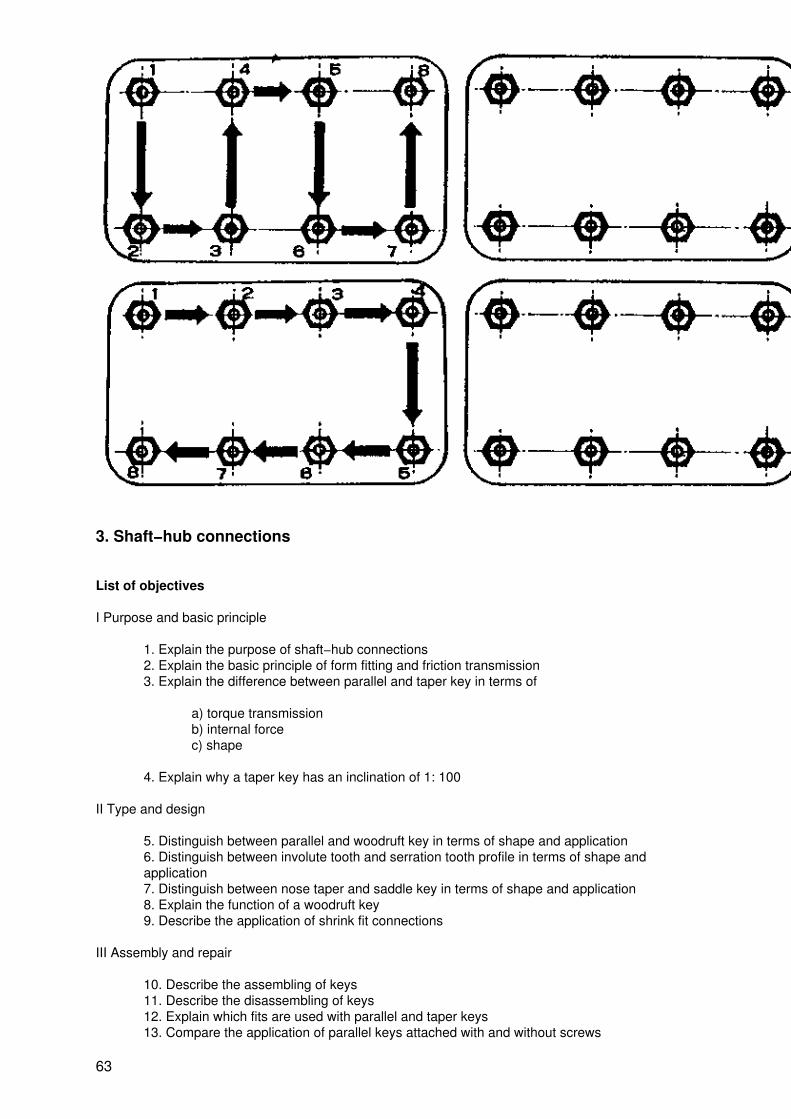
3.4 Tighten nuts and screws in a certain order
wrong right
32

1. over cross
2. circular
Steps:
1. tighten all nuts moderate in one of the ways shownabove
2. tighten all nuts till full torque is achieved
3.5 Typical screw defects
kind ofdamage
33

bolt breaksthread is damaged
reasons too much torque − too much torque− two different threads− dirty or rusty thread− screw not applied correctly
3.6 Extract broken bolts and repair internal threads
a) Extractor
b) slotting
c) pente trating oil
34

− happens especially when the materialof the workpiece is soft (e.g. aluminium)
repair
1. Screw bush
− a screw bush acts like a self−cuttingscrew
2. Helicoil
− for a helicoil a thread must be tapped
3.7 Retightening the nut after some service time
a) Vibration during work
duringwork
35

aftersomeservicetime
b) Vibrations and heat during work
Task sheet
1.1.a) A joint, which must be destroyed when dismounting is called permanent/detachable
1.1.b) Mark the permanent joints with P and the detachable joints with D!
36

1.2.
a) In the bolt occurs axial/cross load.
b) What happens, when the load F3 is rising?
a) Clamping force F2 is higher/constant/lowerb) Bolt gets longer/constant/shorterc) Load F1 of the screw is higher/constant/lower
37

c) The tank is leaking when the force of pressure is higher/equal/lower than the preload of the screw.
1.2.2
a) If clamping force is not sufficient, the workpieces can slip. In that case, the bolt carries cross/axial load.
b) The workpieces do not slip when
38

c) If the surface of the workpieces is dirty or oily, the clamping force F2 will be lower/equal/higher and islower/equal/higher
d) Capacity of a bolt connection to carry cross load is higher/equal/lower when the surface of the workpiece isdirty or oily.
2.1
a) Write one of the following names under the picture: Tab bolt, Through bolt, Stud bolt
figure
1 ___________ 2 ___________ 3 ___________
b) Which of the screws mentioned above is used?
1 ___________ 2 ___________ 3 ___________
2.2
a) The bolt which prevents movement of the workpieces is called screw/fitting bolt/stud bolt
b) Which drawing shows a fitting bolt?
39

1.
2.
40

2.3 Which screws fit in the following applications? Write the correct number in the square!
a) 1.
b) 2.
c) 3.
d) 4.
41

e) 5.
2.4 Relate the text on the right hand side to the Nuts on the left hand side
−−−−−−−−−− a) protects from water and dirt
−−−−−−−−−− b) for general use
−−−−−−−−−− c) protects from loosening
−−−−−−−−−− d) can be tightened by hand
2.5 Write the letter in the square!
a) Which screws (bolts) fit in the following applications?
42

1. a)
2. b)
3. c)
4. d)
43

e)
b) Which nuts fit in the following applications?
1. a)
2. b)
44

3. c)
4. d)
2.6
a) Complete the code!
45

a) Code: M........... b) M............. c) M................
b) You need a screw with a tensile strength of 500 N/mm2 and elastic limit of 300 N/mm, which marking mustthe screw−head have?
2.7 The nut/screw is normally tightened at a screw joint. The washer must be placed under the screwhead/nut to
a) protect the surface of the workpiece under the nutb) protect the surface of the workpiece under the screw−headc) protect from looseningd) protect from friction between screw−head and hole
2.8
a) Relate the types of lockings to the Nuts!
a) from fitting lockb) friction lock
b) Fill in the numbers 1.2, 3, 4, 5, 6 of 2.8.a) in the empty lines below!
a) Makes use of the friction between the nutsb) Use when heavy vibration occursc) Makes use of the friction of deformed plasticd) Permanent joint will be destroyed when loosened
46

3.1 a) Relate the right tool to the screws in the table below!
Types of screws Tools
a) b) 1. Open end wrench2. Two−hole−key3. Hook wrench
c) d) 4. Ring spanner5. Screw driver6. Alien key
e) f) 7. Phillips screw driver8. Adjustable wrench9. Vise grip wrench
Types of nuts & screws a) b) c) d) e) f)
Tools
b)
For a hexagon screw M10 a wrench No. − 13/17/19 − is used.For a hexagon screw M12 a wrench No. − 15/17/19 − is used.
3.2
a) When tightening 2 screws with the same torque, the friction in an oily screw is higher/lower than in a rustyone.
b) When they should have the same clamping force, the torque at a rusty screw must be higher/lower than ata oily one.
3.3
a) We are using the torque wrench to
a) tighten nuts when only limited space is availableb) reach a higher torquec) reach the desired torqued) tighten faster than with a usual wrench
b) Where do you get the information about the correct torque from?
− scale of torque wrench/Machine manual/screw−head
47

3.4
a) Write the correct tightening sequence in the circles!
b) Mark the correct answers with!
When tightening in the wrong sequence!
1. the flange might leak2. the clamping pressure is higher3. the clamping force is unsymmetrical4. the screws are overloaded
3.5 Mark the correct answers with!
To prevent the thread of a screw from damage, you should
a) center the wholes before inserting screwb) use a bigger wrenchc) pay attention to the maximum tensile strengthd) choose the right type of screw (e.g. Hexagonal screw)e) pay attention to the kind of thread
3.6
a) Relate the drawings to the text
1. Saw a slott and loosen the screw by screw driver2. Weld a piece of iron on the screw and loosen by pliers3. File across flats and open by wrench4. Drill a whole and loosen by extractor
48

b) Which method would you use for repairing thread without tap? helicoil/thread bush
c) Which method of thread repair requests a tap? helicoil/thread bush
3. 7 Mark the correct answer with Which connection must be tightened after some service time?
a) boiler b) shaper tool c) water pipe
Solutions
1.1
a) permanent
b)
a) P b) P c) P d) D e)D
1.2
a) axial
b)
a) higherb) shorterc) lower
c) higher
1.3
a) cross loadb) F2 F3c) equal lowerd) lower
2.1
a) 1. stud 2. screw 3. bolt
b) 1. screw 2. bolt 3. stud
2.2
a) fitting boltb) b)
49

2.3
a) 3 b) 5 c) 2 d) 4 e)1
2.4
a) c) d) b)
2.5
a) 1. c) 2. d) 3.1 b) 3.2 e) 4. a)
b) 1. c) 2. d) 3. a) 4. b)
2.6
a) a) M10 × 35 b) M10 c) M12 × 60
b) 5.6
2.7
Nut Nut a)
2.8
a) 1. a) 2. b) 3. b) 4. a) 5. b) 6. a)
b) a) 5 b) 4, 1, 6 c) 2 d) 1, 6
3.1
a) a) 7 b) 5 c) 6 d) 1 e) 3 f)2
b) 17 19
3.2
a) lowerb) higher
3.3
a) c)
b) Machinemanual
3.4
a)
b) 1 2 3 4
3.5
a) b) c) d) e)
3.6
a) 1.a) 2.b) 3.a) 4.c)
50

b) thread bush
c) helicoil
3.7
a, b
FEATURE OF WORKPIECE CONNECTIONS
Permanent joint
Detachable joint
F2 = Clamping force
51

INTERNAL FORCE IN BOLT
F1 = Load of bolt
AXIAL LOAD
No preload Preload Preload and outside force
F1 = load of boltF2 = clamping forceF1 = F2
F2 = F1 − F3F1 > F3
CROSS LOAD
Clamping force Clamping force to low Oil or dirt
52

F2 · µ > F3 F2 · µ < F3 F2 · µ < F3
Screw
Bolt
Stud
TYPES OF SCREWS
53

socket head screw
countersunk head screw
square head shoulder screw
sheet metal screw
TYPES OF NUT
hexagon nutSquare nut Two hole nut
Slotted nut
Wing nutKnurled nut Cap hut
Castel nut
54

STANDARD OF SCREW, NUT AND STUD
55
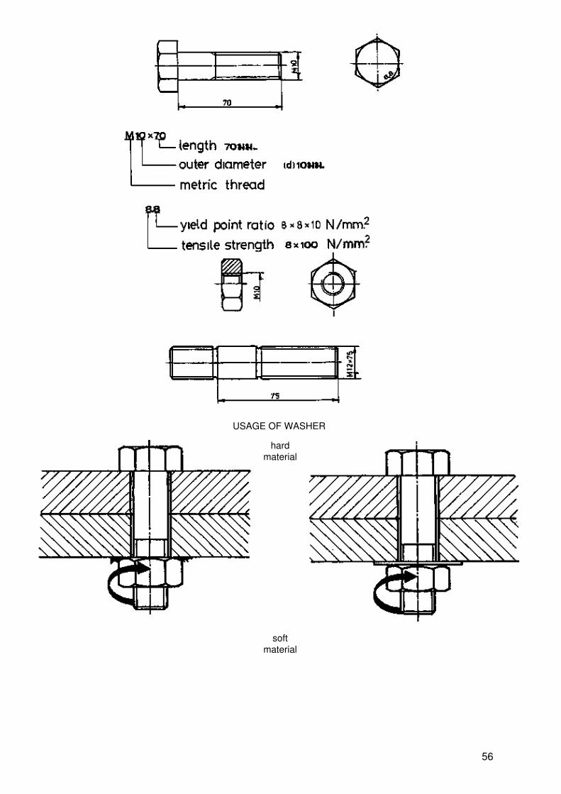
USAGE OF WASHER
hardmaterial
softmaterial
56

FRICTION LOCKS
Fan discs Spring washers
Counter nut Self locking nut
FITTING LOCKS
57

Tap washer locking plate
Safety wire Split pin
FEATURE OF BOLT AND SCREW DEFECTS
Reasons − too much torque − too much torque
58

− two different thread− screw not applied correctly− dirty or rusty thread
RUST AND OIL IN THREAD
µ1>µ2T1>T2F2n=F2(...)
USAGE OF TORQUE WRENCH
59

EXTRACT BROKEN BOLTS FROM WORKPIECE
use extracteruse saw and screw out by screw driver
REPAIR INTERNAL THREAD
1 Screwbush
2 Helicoil
60

during work
after some service time
61

When heated and vibrated, stud will be elongated
1. Over cross
2. Circular
TIGHTEN NUTS AND SCREWS IN A CERTAIN ORDER
62
3. Shaft−hub connections
List of objectives
I Purpose and basic principle
1. Explain the purpose of shaft−hub connections2. Explain the basic principle of form fitting and friction transmission3. Explain the difference between parallel and taper key in terms of
a) torque transmissionb) internal forcec) shape
4. Explain why a taper key has an inclination of 1: 100
II Type and design
5. Distinguish between parallel and woodruft key in terms of shape and application6. Distinguish between involute tooth and serration tooth profile in terms of shape andapplication7. Distinguish between nose taper and saddle key in terms of shape and application8. Explain the function of a woodruft key9. Describe the application of shrink fit connections
III Assembly and repair
10. Describe the assembling of keys11. Describe the disassembling of keys12. Explain which fits are used with parallel and taper keys13. Compare the application of parallel keys attached with and without screws
63

14. Describe the assembling and disassembling of parallel keys attached with screws15. Describe the assembling of a shrink fit16. Describe the disassembling of a shrink fit
Information sheet
1. Purpose and basic principle
1.1 Torque transmission between shaft and hub
− Torque transmission from shaft to hub
− Torque transmission from hub to shaft
64

1.2 Two ways of torque transmission
1.2.1 by form
1.2.2 by friction
1.3 Internal force and flow of torque
1.3.1 Parallel key
− rotating centre of hub true− all torque (T) flows through the parallel key
65

1.3.2 Taper key
− rotating centre out of true because of excentricity between shaft and hub− torque flow is divided
1.4 Key slope
− low force due to high inclination− not self locking
− high force due to low inclination− self locking
66

2. Types and design
2.1 Design and application form fitting joints
− used for high torque transmission
− used for low torque transmission. Due to the key groove depth, the strength of shaft isreduced.
− used for high torque and lever connection
− used for very high torque transmission and as a slide way for gear wheels
2.2 Shape and application of friction joints
67

− is used for high torque transmissions and low revolutions
− is used for low torque transmission and low revolution− shaft and hub can slip in case of high torque
− used with taper shaft function as locating element. Torque transmission due to the frictionbetween tapered wheel and shaft.
− is used, when the connection is not disassembled very often.
3. Assembling and repair
68

3.1 Assembling of keys
3.1.1 form fitting joints
1. − put thekey in thekeyway
1. − put thekey in thekeyway
2. − fit it witha softhammer
2. − fit it witha softhammer
3. −hammer*around thehub until itfits on theshoulder,then lookit with anut
3. −hammer*aroundthe hubuntil it fitson theshoulderthen lockit with anut
* use only a soft hammer
3.1.2 Friction joints
− cut akeyway
−assemblehub andshaft
69

−assemblehub andshaft, thenput a nosetaper keyin thekeyway
− put ataper keyin in thekey way
− hammeron the keygrip until itfits
− hammeron the keytill it fits
3.2 Disassembling of Keys
3.2.1 Form fitting joints
− disassemble the hub with a puller
− remove the key with pliers
70
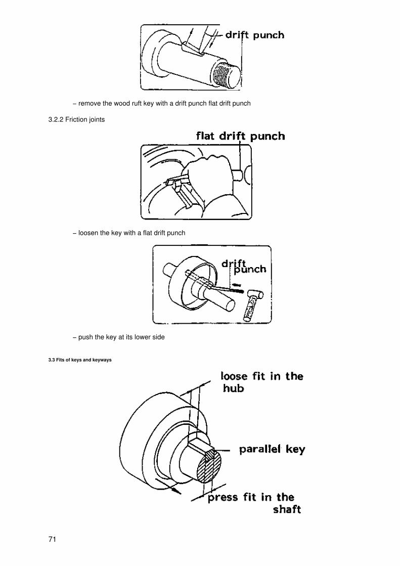
− remove the wood ruft key with a drift punch flat drift punch
3.2.2 Friction joints
− loosen the key with a flat drift punch
− push the key at its lower side
3.3 Fits of keys and keyways
71

Note: The fits can be found in the table book
3.4 Parallel Keys fixed with screws
− the screws are fixing the key while the hub is moving
− parallel key without screw is used for a fixed hub
72

− assembling of a parallel key by tightening the screws
− disassembling of a parallel key by tightening the key−drawer screw
3.5 Assembling and disassembling of a shrink fit
− heat the hub before assembling
73

− put the hub on the shaft immediately− let it cool down in the atmosphere
3.6 Disassembling a shrink fit
− disassemble the shaft with a press
Note: Lubricate with oil to avoid damage of hub and shaft.
Task sheet
1.1
a) The purpose of a shaft − hub connection is to __________________b) Fill in the works "Shaft" or "bus" in the emty lines below!
74
Torque transmission from 1 to 2 transmits from ________to ________Torque transmission form 3 to 4 transmits from ________to________
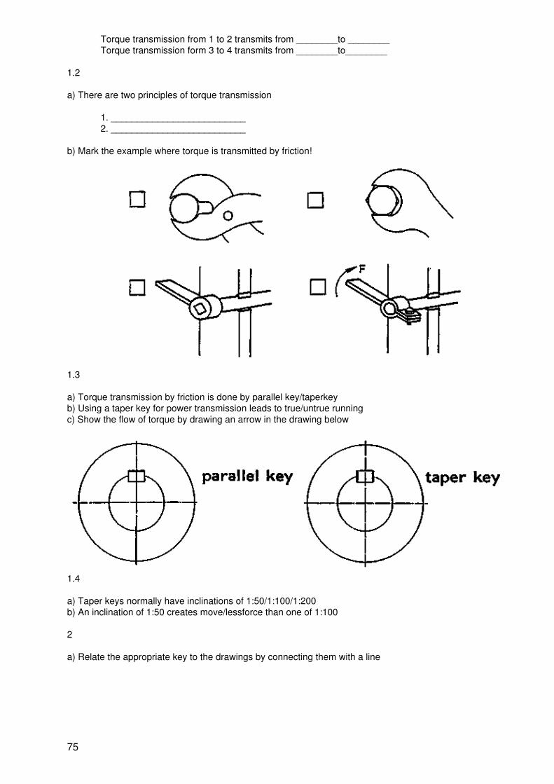
1.2
a) There are two principles of torque transmission
1. __________________________2. __________________________
b) Mark the example where torque is transmitted by friction!
1.3
a) Torque transmission by friction is done by parallel key/taperkeyb) Using a taper key for power transmission leads to true/untrue runningc) Show the flow of torque by drawing an arrow in the drawing below
1.4
a) Taper keys normally have inclinations of 1:50/1:100/1:200b) An inclination of 1:50 creates move/lessforce than one of 1:100
2
a) Relate the appropriate key to the drawings by connecting them with a line
75

Name the keys and add their applications by filling in the appropriate letters and numbers
b)
Name Application
a) saddle keyb) nose taper keyc) parallel keyd) woodruft keye) involute splind shaftf) survateted shaft
1. for high torque and revol.2. for high torque and lowrevolution3. for high torque and axialmovable4. for low torque5. for high torque and leverconnection6. for low torque and lowrevolution
c)
76

d) A woodruft key which is used with a tapered shaft
is fixing the hub in the centeris fixing the hub in a certain position to the shaftprevents axial movement of the hub
e) A shaft−hub connection which is very seldom disassembled can be realized as a tapered shaft/shrinkfit/involute spline shaft
f) Which type of key can be used easily at any position of the shaft? A nose taper key/a woodruft key/a saddlekey
g) Which type of key is located at the end of a shaft without any additional fixing elements? A nose taper key/aparallel key/a woodruft key
h) Relate the appropriate key to the drawings by connecting them with a line!
3.1
a) Sketch the appropriate key way on the shaft!
77

b) Write the correct sequence of assembling a parallel key in the lines
1. ________________________2. ________________________3. ________________________
c) Sketch the appropriate key way on the shaft!
d) Write the correct sequence of assembling a taper key in the lines!
78

1. _______________________2. _______________________3. _______________________
3.2
a) How is a parallel key dismounted?
By using a drift punch to remove the keyBy sliding a wheel along the shaft axisBy using pliers to remove the key
b) Which type of key is disassembled by pushing it out along the shaft axis with a drift punch?
a parallel keya saddle keya woodruft key
3.3
a) A parallel key is mounted in the key way of the shaft with a press fit/loose fitb) A taper key is mounted in the key way of the hub with a press fit/loose fit
3.4
a) A parallel key with fixing screw is suitable for
a wheel which moves on the shaftlow torque transmissiona joint which is often dismounted
b) Describe the function of the threads in the key shown in the figure below.
3.5 When assembling shaft and hub by shrink fit the following jobs must be done:
heat the shaft/mount the hub on the shaft by handheat the hub/mount the hub on the shaft by a press
79

heat the hub/mount the hub on the shaft by hand
3.6. What must be considered to avoid damage of shaft and hub when dismounting them with a press?
Solutions
1.1
a) transmit torque
b) shaft to gear wheelgear wheel to shaft
1.2
a) torquetransmissionby interlocktorquetransmissionby friction
b) x
x
1.3
a) taper keyb) untrue runningc)
1.4
a) 1:100
b) less
2.
80

a)
b)
c)
d) x is fixing the hub in a certain position to the shaft
e) shrink fit
f) saddle key
g) nose taper key
h)
3.1
81

a)
b) 1. put a parallel key in the key way2. fit it with a soft hammer3. hammer around the hub until it fits on the shoulder and lock it
c)
d) 1. mount hub with shaft2. insert the key in key way3. hit it with a hammer until it fits
3.2
a) x By using pliers to remove the key
b) x a saddle key
3.3
a) press fit
b) loose fit
3.4
a) x a wheel which moves on the shaft
b) 1. thread for dismounting key2. thread for fixing screw
3.5
x heat the hub/mount the hub on the shaft by hand
3.6
to put oil on the shaft
82

Form Friction Transmission
83

Torque Transmission
84

Parallel Keys fixed with serews
Usage assembly and disassembly
Form Fitting Keys Assembly
85

Keys Disassembly
Form Friction Keys Assembly
Hub Assembly and Disassembly
86

Assembly with heat
Disassembly with press
Key Slope
87

low force due to high inclination
high force due to low inclination
Fit For Keys Assembly
Parallel key
88

Taper key
Flow of torque
rotating centre of hub true
rotating centre out of true
Form Fitting Transmission
89

parallel key
surrated shaft
woodruff key
involute splinded shaft
Shaf−hub Connections
90

Torque transmission shaft to hub
Torque transmission from to shaft
4. Couplings and Clutches
List of Objectives
I Purpose and basic function
1. Explain the main functions of couplings and clutches2. Explain the differences between couplings and clutches3. Explain the different principles of friction and form clutch
II Types and design
4. Name the parts of a single disc clutch and explain their function5. Explain which factors effect the efficiency of a friction clutch6. Name the parts of a multiple disc clutch and explain their function
91

7. Show the flow of torque in a friction clutch8. Show the flow of torque in a form clutch9. Explain the function of a safety clutch10. Distinguish between rigid and flexible couplings11. Describe the feature of plate and clamp couplings12. Describe the feature of rubber and spring couplings13. Describe the feature of an universal joint
III Maintenance and repair
14. Explain how to maintain a single disc clutch15. Explain how to maintain a multiple disc clutch16. Explain how to maintain an universal joint17. Explain how to repair a rubber coupling
Information sheet
1. Purpose and basic function
1.1 Purpose
Couplings and clutches are machine elements, which transmit torque from the driving shaft to the driven shaft.
1.2 Difference between couplings and clutches
Couplings are not shiftable during work
Clutches are shiftable during work
92

−frictionclutch
− formfittingclutch
2. Types and design of clutches and couplings
2.1 Friction clutches
2.1.1 Single disk clutch
a friction clutch
− can be engaged and disengaged while rotating− can be engaged and disengaged under load− is starting smoothly big contact area small contact area
93
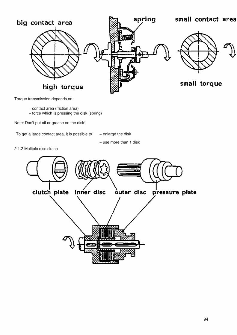
Torque transmission depends on:
− contact area (friction area)− force which is pressing the disk (spring)
Note: Don't put oil or grease on the disk!
To get a large contact area, it is possible to − enlarge the disk
− use more than 1 disk
2.1.2 Multiple disc clutch
94

Note: Inner and outer discs need oil for cooling during work
2.2 Form fitting clutch
2.2.1 Jaw clutch
A form clutch
− can be engaged while rotating− cannot be engaged or disengaged under load
95

2.2.2 Safety clutch
A safety clutch is self−disengaging when the torque is higher than the friction generated by spring and jaws.
2.3 Rigid coupling
2.3.1 Plate coupling
96

When mounting or dismounting:
− shafts must be in alignment
− 1 shaft must be shiftable in a axial direction.
2.3.2 Clamp coupling
− shafts must be in alignment
− shaft must not be shifted in axial direction.
2.4. Flexible coupling
2.4.1 Rubber type
97
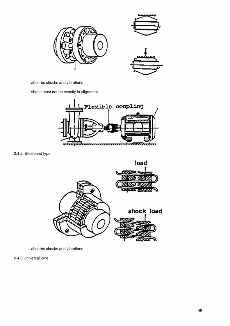
− absorbs shocks and vibrations
− shafts must not be exactly in alignment.
2.4.2. Steelband type
− absorbs shocks and vibrations
2.4.3 Universal joint
98

The shafts can be misaligned and excentric.
3. Maintenance and Repair
3.1 Single disc clutch
When the friction lining is worn till the rivet, it must be replaced.
3.2 Multiple disc clutch
99

Change oil according to the manual
3.3 Jaw clutch
Grease the teeth of the clutch
3.4 Universal joint
Grease it according to the manual
100

3.5 Flexible coupling
Replace the rubbers when they are damaged.
Task sheet
1.1 The main task of couplings and clutches is _____________________
1.2
a) Mark the correct answer with X!
1. Coupling
2. Clutch
3. can beengagedanddisengagedwhile
101

rotating
4. can beengagedanddisengagedunder load
b) Mark the correct answer with X!
1. can beengaged ordisengagedunder load
2. can beengagedwhilerotating
3. can bedisengagedwhilerotating
4. reducesstartingtorque
5. transmitstorque byform
6. transmitstorque byfriction
7. can beengagedonly when n= 0
c)
102

Torque is transmitted from shaft a to shaft b by 4 different parts. Show the flow of torque by arranging thenumbers in the correct sequence!
d)
Show the flow of torque from shaft P to shaft Q by arranging the numbers in the correct sequence!
2.1
a) Name the parts and add their functions by filling in the appropriate letters and numbers.
name function
103

a) springb) discc) clutchplated) levere) pressureplate
1. transmits torque through thedisc to driven shaft.2. engages/disengages clutch3. generates friction4. generates pressing force5. presses the disc
b) Mark the correct answer with X!
1. big contactarea
2. smallcontact area
3. hardspring
4. soft spring
104

5. low torquetransmission
6. hightorquetransmission
c) Name the parts and add their functions by filling in the appropriate letters and numbers
name function
a) innerdiscb) outerdiscc)pressureplated) clutchplate
1. transmitstorquethrough discto drivenshaft2. generatesfriction androtates withclutch plate3. generatesfriction androtates withpressureplate4. pressesdisc
d) Mark the correct answer with X!
1. contactarea canbe variedby thediameterof disc
105

2. contactarea canbe variedby thenumberof discs
3. cooledby air
4. cooledby oil
5. thediscmaterialis steel
e. thediscmaterialisasbestos
2.
a) Name the couplings/clutches and add their functions by filling in the appropriate letters and numbers
name function
a) form clutchb) friction clutchc) rigid couplingd) flexible coupling
1. eliminates vibration2. can be engaged or disengaged under load3. assembled shafts can have little misalignment4. is reducing starting torque
Note: A coupling/clutch can have various or none of the mentioned functions!
b) When does the safety clutch interrupt torque transmission?
− If the vibrations are too high− If the torque is higher than the friction generated by spring and jaws− If the pressure F generated by the spring is too high
c) Mark with R for rigid coupling and F for flexible coupling!
106

Shafts must be in alignment for assemblingShafts can be a little misalignedAbsorbs shocks and vibrations
d) Name the couplings/clutches and add their functions by filling in the appropriate letters and numbers
name:a) plate couplingb) flexible couplingc) universal joint
function:1. Absorbs shocks and vibrations2. Shafts can be excentric3. For assembling/disassembling shafts must beshifted in axial directions
Note: A coupling can have various functions
3. Explain how the couplings/clutches are maintained by filling in the appropriate letter
_____ 1. Maintenance:a) smear with greaseb) change disc (or lining)c) change rubbersd) change oile) inject grease
_____ 2.
107

_____ 3.
_____ 4.
_____ 5.
Solutions
1.1 ..... to transmit torque
1.2
a)
b)
108

c)
d)
2.1
a)
b)
109

c)
d)
2.
a)
b) If the torque is higher than the friction generated by spring and jaws.
c)
110

d)
3.
Safety clutch
Plate coupling
111

Friction clutches: Single disk clutch
Form fitting clutch: Jaw clutch
112

Type of Clutch
Friction clutch
Form fitting clutch
Friction clutches Multiple disk clutch
113

To get a large contact area by use more than 1 disk
Clutch Maintenance
Single disk clutch
Before use After use for a while
Multiple disk clutch
114

Factor which in effect to torque transmission of Single disk clutch
Efficiency of torque transmission depends on:
− Contact area− Force which is pressing the disk
Maintence Flexible Coupling
Rubber coupling
115

Replace the rubbers when they are damage
Universal joint
Grease it according to the manual
Clamp coupling
116

Material of Single disk clutch
117
Note: Don't put oil or grease on the disk
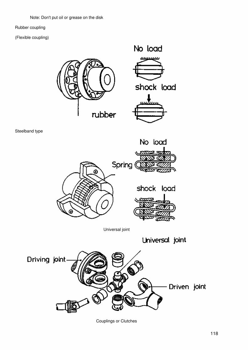
Rubber coupling
(Flexible coupling)
Steelband type
Universal joint
Couplings or Clutches
118
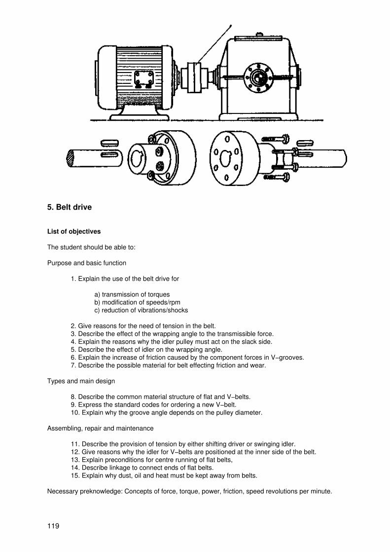
5. Belt drive
List of objectives
The student should be able to:
Purpose and basic function
1. Explain the use of the belt drive for
a) transmission of torquesb) modification of speeds/rpmc) reduction of vibrations/shocks
2. Give reasons for the need of tension in the belt.3. Describe the effect of the wrapping angle to the transmissible force.4. Explain the reasons why the idler pulley must act on the slack side.5. Describe the effect of idler on the wrapping angle.6. Explain the increase of friction caused by the component forces in V−grooves.7. Describe the possible material for belt effecting friction and wear.
Types and main design
8. Describe the common material structure of flat and V−belts.9. Express the standard codes for ordering a new V−belt.10. Explain why the groove angle depends on the pulley diameter.
Assembling, repair and maintenance
11. Describe the provision of tension by either shifting driver or swinging idler.12. Give reasons why the idler for V−belts are positioned at the inner side of the belt.13. Explain preconditions for centre running of flat belts,14. Describe linkage to connect ends of flat belts.15. Explain why dust, oil and heat must be kept away from belts.
Necessary preknowledge: Concepts of force, torque, power, friction, speed revolutions per minute.
119

Information sheet
1. Purpose and basic function
1.1 Purpose
− Torque transmission from driving pulley to driven pulley− Changing the RMP's− Absorb vibration or shock load
1.2 Basic function
1.2.1 Tension
− Low torque transmission− The belt slips
− Torque is transmitted by adherence.− The tension is necessary to create friction between pulleys andbelt.
1.2.2 Wrapping angle
120

− Wrapping angle 1 2− If the wrapping angle is big, the pulley can transmit high torque.
1.2.3 Idler
Idler position
− When pressing on a belt's tight side with an idler, it will be high load on the idler.
− When pressing on a belt's slack side with am idler, it will be low load on the idler.
Effect of an idler
121

− small wrapping angle less contact − surface low torque transmission
− big wrapping angle more contact surface high torque transmission
1.2.4 V−groove
− low pressing force low friction low torquetransmission
− high pressing force high friction high torquetransmission
1.2.5 Materials and its property
Property Friction coefficient (µ) Tensile strength Elasticity Wear resistance
Material
leather 0.6 medium low medium
rubber 0.4 low high medium
synthetic 0.2 high low high
122

2. Types and design
2.1 Material − structure of belts
2.2 V−belt code
ISO A B C D
DIN 13 17 22 32
Note: ISO Standard specifies the length in inch and mm.
123

2.3 Groove angle and pulley diameter
− The groove angle depends on the pulley diameter, a pulley with small diameter will have asmaller groove angle than one with big diameter.
Note: For more detailed information see table book!
3. Assembling and repair
3.1 Adjustment of tension
124

When the distance between two pulleys is fixed, the tension of a belt is adjusted by an idler.
When the distance between two pulleys is not fixed, the tension of a belt is adjusted byadjustment screw.
Note: If the belt is flattering or squeaking, it must be adjusted.
3.2 Idler position for V−belts
125
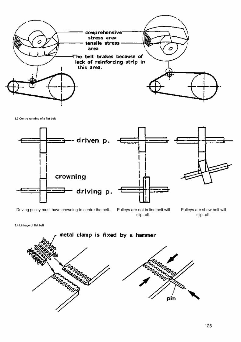
3.3 Centre running of a flat belt
Driving pulley must have crowning to centre the belt. Pulleys are not in line belt willslip−off.
Pulleys are shew belt willslip−off.
3.4 Linkage of flat belt
126
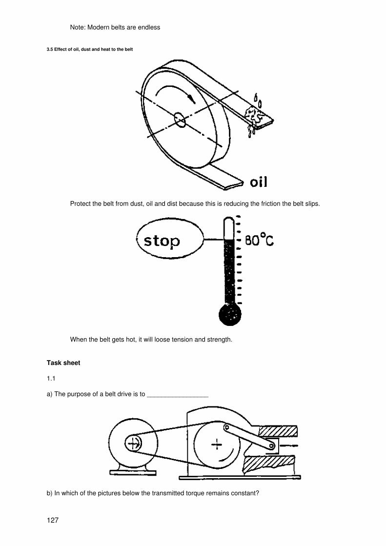
Note: Modern belts are endless
3.5 Effect of oil, dust and heat to the belt
Protect the belt from dust, oil and dist because this is reducing the friction the belt slips.
When the belt gets hot, it will loose tension and strength.
Task sheet
1.1
a) The purpose of a belt drive is to _________________
b) In which of the pictures below the transmitted torque remains constant?
127

1.2
a) Power transmission is insufficient when
1. a belt is too tight2. a belt is loose3. the belt is too wide
b) For torque transmission by a belt its length/friction coefficient/elasticity is important.
c) Which pulley transmits maximum torque
d) Which belt has the smallest wrapping angle?
e) When using an idler at the slack side of a belt drive, the consequence is that
1. the belt slips2. the belt is overloaded3. the pressure at the idler is high4. the pressure at the idler is low
f) Which figure shows the correct rotating direction?
g) When using an idler, the contact surface between belt and pulley will increase/decrease and torquetransmission will increase/decrease.
h) Which belt must be more tight?
1. V−belt 2. Flat belt
i) A V−belt creates more/equal/less friction than a flat belt.
j) Indicate the component forces by drawing arrows.
128

k) Pair the belt material with its specific property:
1. high friction _____ leather
2. high elasticity ____ plastic/fiber
3. high tensile strength ____ rubber
4. high wear resistance
2.1 Which parts of a V−belt are related to the following properties?
− tensile strength− wear resistance− elasticity
2.2
a) Explain the belt code!
b) Write a code to order a belt according to DIN whose width is 17 mm and length 900 mm.
2.3
a) Which belt fits?
129

1 = ______2 = ______3 = ______
b) Which picture shows a pulley with big diameter?
3.1 Fill in the right number to the statements
___ Wrapping angel and tension increases___ Only tension of the belt increases___ Adjustment by screw___ Transmits maximum torque___ Distance between pulleys remains constant
3.2
a) This damage happens to a V−belt when
130

not using an idlerthe belt is too tightidler is located outside of beltidler is located inside of belt
b) Complete the drawing!
c) A flat belt will slip because
the belt is too tightthe pulley has no crowningthere is no idlerthe pulleys are not in line
3.3
a) What will be the effect when the pulleys are not poraxial?
The ratio of power transmission will decreaseThe belt will slip−off from the pulleyThe belt will slipThe belt will wear
b) The pulley with crowning is used for driving/driven pulley.
Its purpose is to prevent the belt from slipping/slip−off.
3.4 Write down the steps of joining a flat belt with a steel clamp:____________________________________________________________
3.5
a) Which effect has oil and dust on a belt?____________________________________________________________
b) Which effect has overheating to the belt drive?____________________________________________________________
131

Solutions
1.1
a) − transmit torque from the driving to the driven pulley− change RMP's− absorb vibrations or shock load
b) 2
1.2
a) 2
b) friction coefficient
c) 1
d) 3
e) 4
f) 2
g) increase − increase
h) 2
i) more
j)
k) − leather 3, 4 plastic/fiber 1, 2 rubber
2.1
2 tensile strength 1 wear resistance 3 elasticity
2.2
a) international standardwidthlength
b) DIN 17 × 900
2.3
a) 1
b) 1
3.1
2 wrapping angel and tension increases1 adjustment by screw1 only tension of the belt increases2 transmits maximal torque2 distance between pulleys remains constant
3. 2
a) the idler is located outside the belt
b)
c) there is no idler
132

3.3
a) the belt will slip−off from the pulley
b) driving pulley slip−off
3.4
fix metal clamps with a hammer and connect them with a pin
3.5
a) the belt slips
b) the belt will loose tension and strength
THE GROOVE ANGLE DIAMETER OF PULLEY
STRUCTURE OF BELTS
133

THE REASON WHY IT IS NECESSARY TO ADJUST THE TENSION IN BELT
belt slack side belt tight side
slip have friction at contact surface
(T1 T2)
power cannot transmission power can transmission
ADJUSTMENT OF TENSION
134

By idler By adjustment screw
HIGH FRICTION OF BELT
Flat belt V − belt
Low friction force High friction force
CODE OF V−BELT
Comparison table of ISO and DIN standard
ISO A B C D
DIN 13 17 22 32
135

IDLER POSITION
normal wrapping angle
increase wrapping angle ?
pressing on belt slack sidenear the driving pulley
IDLER POSITION OF V−BELT
LINKAGE OF FLAT BELT
136

WRAPPING ANGLE OF PULLEY
Wrapping angle is small (?1) Wrapping angle is big (?2)
low contact surface high contact surface
slip no slip
low power transmission high power transmission
6. Gears
List of objectives
I. Purpose and basic principle
1. To describe the purpose of power transmission by gear according to the following subjects:
− transmission of torque
137

− change of revolution
2. To distinguish between friction transmission and form transmission according to thefollowing subjects:
− slip− revolution− torque transmission− transmission character
II. Design
3. To explain how to construct an involute curve4. To describe the definition of the following dimensions: p, d, h, ha, hf, b, da, and df5. To explain the pressure angel6. To determine the above mentioned dimensions with the help of a formula−table7. To explain why a pair of gear can only be engaged when they have the same module8. To explain the definition of module9. To describe the negative effect of undercut at gears with less with less than 14 teeth10. To explain how to prevent undercut
III. Types and application
11. To describe shape and application of the following gears: spur, helical, bevel and worm12. To describe shape and application of rack and pinion13. To explain the advantage and disadvantage of torque−transmission by different types ofgears
IV. Types of gear boxes
14. To describe the character and application of the following types of gears: fix ratio, changegear, shift gear, driving gear, norton gear, planetary gear, back gear and idle gear,
15. To explain how to change the revolution of a shifting gear
V. Maintenance and repair
16. To describe how to check pitch, module and backlash of a gear17. To explain the need of backlash18. To describe how a gear is repaired19. To name at least 3 types of gear−material and consider their selections20. To explain why the material of a small gear should have better quality than a big one21. To explain at least 3 methods of lubrication22. To choose the right lubrication method for different jobs
Information sheet
1. Purpose and basic principle
1.1 Purpose
138

− to transmit torque from the driving to the driven gear− to change the revolution
1.2 Basic principle
sliprevolutionpowertransmissionlock
Yesnot constantlowfriction
Noconstanthighform fitting
2. Design
2.1 Construction of involute curve
139

An involute curve is generated by unwinding from the circumference of a circle
Note: Gears with involute teeth are widely used because of minimum friction.
2.2 Dimensions and calculation of spur gear
140

Name Symbol Formula Size
gear1 gear2
pitch P 15.7
number of teeth z 20 30
module m 5
pitch circle diameter d 100 150
height of tooth h h = ha + hf 11
addeudum ha ha = 1m 5
dedendum hf 5.83
width of face b 40
outside diameter da da = d + 2m 110 160
root diameter df df = d − 2hf 98.34 148.34
crest clearance c 0.83
axial distance a 125
pressure angel ? 20º
141

2.3 Pressure angel
Along the common normal, the teeth are in contact (pressure) while the gears rotate.The angel between tangent x and common normal is the pressure angel
2.4 Module and pitch
U = d.?
module table (mm)
module 1.0 1.25 1.5 2.0 2.5 3.0 4.0
pitch 3.142 3.927 4.712 6.283 7.854 9.425 12.588
module 5.0 8.0 8.0 10.0 12.0 18.0
142

pitch 15.708 18.850 25.132 31.416 37.699 50.265
Note: gears with different module dp not fit
2.5 Undercut modification
a) normal gear b) gear with less than 14 teeth c) undercut is avoided by shifting the pitch circle
gear tooth is normal gear tooth is weakened gear tooth is strong
3. Types and application
3.1 Paraxial
Type Application Advantage Disadvantage
Spur gears
feed gear box
easy to produce noisy
Helical gears
oil pump
runs more silentlythan a spur gear
− axial force− more difficultto producethan a spurgear
143

3.2 Intersection axis
Type Application Advantage Disadvantage
Bevel gear
hand driller
can transmit torque whenshafts cross each other
− difficult toproduce− axial force
3.3 Cross axis
Type Application Advantage Disadvantage
Worm gear
dividing head
− high transmission ratio forspeed and torque− silent
− high friction
Rack and pinion
− can change rotary into linearmovement and vice versa
___
144
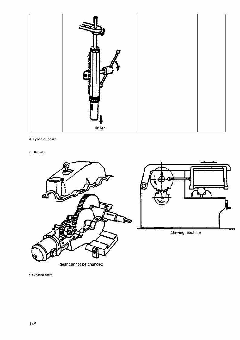
driller
4. Types of gears
4.1 Fix ratio
gear cannot be changed
Sawing machine
4.2 Change gears
145

Revolution is changed by changing gear set.
4.3 Shift gear
146

Steps of changing gear
1st speed: 1 2 2nd speed: 3 4 3rd speed: 5 6
4.4 Norton gear
147

speedchangebyswivelingandslidingthe swivelarm
4.5 Driving key gear
The key is sliding in the hollow axle
4.6 Planetary gear
4.7 Back gear
148

non−working position working position
With the back gear the number of speeds can be doubled.
4.8 Idle gear
Lathe
With an idle gear the direction of rotation can be changed, the number of revolutions remainsconstant.
149

5. Maintenance and repair
5.1 Check gear
1
Pitch can be checked only by a special measuring tool.
2
Module can be checked by simple gauge.
5.1.2 Backlash can be checked by filler gauge.
150

Some backlash should be given to prevent pressing between the teeth of gears
pitch diameter backlash pitch diameter backlash
25 0.635 − 1.016 127 0.152 − 0.229
38 0.457 − 0.686 152 0.127 − 0.203
51 0.356 − 0.508 178 0.102 − 0.178
64 0.279 − 0.406 203 − 229 0.102 − 0.152
76 0.229 − 0.356 254 − 330 0.076 − 0.127
102 0.178 − 0.279 356 − 813 0.051 − 0.102
5.2 Repairing a gear
tooth is broken Tighten the boltsand cut their headsso that the bolts arenot longer than thetooth dept.
file the brokensurface smoothand lay out thecentre of theholes
Weld around thebolts and finish thetooth form with amiller or a file.
drill the holes Check the shape ofthe tooth with agauge.
Note:
Only slow running big gears should be repaired.Small gears, fast running gears and heavy duty gears should be, replaced by a new one.
5.3 Material of gear
Material Advantage Disadvantage
1. cast ivon easy to finish, low friction, sound absorbing, can be hardened brittle, break easily
2. steel high strength, can be hardened friction
3. non ferrous low friction high casts
4. plastic vibration and sound absorbing, low friction low strength, badheat−conductor
151

The revolution of the small gear are higher; therefore, their materials must be stronger.
5.4 Lubrication
suitable for low revolutions only
152

suitable for low and medium range revolutions
suitable for:
− small gear box− medium to high revolations
suitable for:
− big gear box− different level of gear sets− high turning speed
Task sheet
1. Complete the text or choose the correct answer
a) The duty of a gear box is to increase or decrease
1............... 2.............
b) If the number of teeth of the driving gear is bigger than the one of the driven gear, the rmp's of the drivinggear is bigger/smaller than the one of the driven gear.
153

c) The advantages of power transmission by gear are:
1............. 2............... 3.............
2.1 Which picture shows the generation of an involute curve?
a) b) c)
2.2
a) Relate the right symbols to the dimensions in the table below
d = pitch circle diameterb = width of gearp = pitchh = height of toothda = outside diameterdf = root diameterha = addendumhf = dedendum
1 2 3 4 5 6 7 8
b)
154

d = m.z
h = ha + hf
ha = 1m
da = d + 2m
Symbol Size
driving gear driven gear
m 4 4
z 24 36
d
da
ha
hf
h
a
2.3
a) The line along the teeth are in contact is called _____________b) Normally, the pressure angel is 10°/20°/30°
2.4
a) A pair of gears must have the same d/z/mb) Gears with big module have smaller/equal/bigger size than gears with small module.c) Gears with the same pitch have the same d/z/m
2.5
155

a) This shape of teeth show up when the number of teeth is less than _________b) This shape is called _________c) Indicate in the drawing where the strength of teeth will decrease.d) To prevent undercut the cutting tool is moved towards/away from/to the right of/to the left of/the gear.
3
a) Relate the number in the picture to the gears in the table!
Gear spur bevel worm rack helical
Picture
Property
b) Relate the property of the gears to the names in the table above!
(A gear can have various properties)
156

1. Transmit power when two axles are angeled2. Axial force is arising3. Easy to produce4. High transmission ratio for speed and torque5. Changes rotary movement into a linear one and vice versa6. One way power transmission7. Silent
4
a) Name the gears!
b) Match the type of gear to the specified application (one type of gear can have various applications)
1. Lathe ____ Planetary gear
2. Drilling machine ____ Shifting gear
3. Automobile automatic ____ Norton gear
4. Sawing machine ____ Fix ratio
____ Back gear
c) Sketch the gears to
1. Maximum speed 2. Minimum speed
d)
157

− Sketch the gears number 3 and 7 so that the axle 8 has maximum speed.− How many steps of speed reduction can be realized by this gear box?− The gear drives at lowest speed when gear number ____ and number _______ match.− The type of the gear box is ______
e)
* power−input
− Show the flow of power by sketching arrows.− How many steps of speed reduction can be realized by this gear box?− The type of the gear box is ____
f) Sketch idle gear(s) between driving and driven gear without changing the transmission ratio.
158
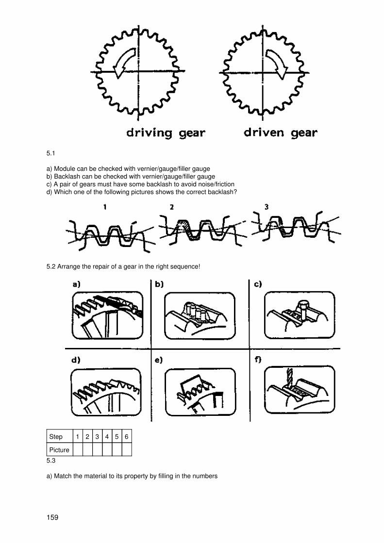
5.1
a) Module can be checked with vernier/gauge/filler gaugeb) Backlash can be checked with vernier/gauge/filler gaugec) A pair of gears must have some backlash to avoid noise/frictiond) Which one of the following pictures shows the correct backlash?
5.2 Arrange the repair of a gear in the right sequence!
Step 1 2 3 4 5 6
Picture
5.3
a) Match the material to its property by filling in the numbers
159

1. Cast iron2. Steel3. Non ferrous metal4. Plastic
____ high strength, can be hardened____ low strength, bad heat conductor____ brittle (breaks easily)____ high costs____ easy to finish, low friction, can be hardened, sound absorbing____ Vibration and sound absorbing, low friction
b) The revolutions of a small/big gear are higher/lower; therefore, its material must be stronger.
5.4 Match the lubrication−systems to their application! (more than one answer is possible)
_____ suitable for low and medium range revolution_____ suitable for big gear box_____ suitable for low revolutions only_____ suitable for small gear box and medium to high revolutions_____ suitable for different levels of gear sets_____ suitable for high revolutions
Solution sheet
1.1
a) 1. torque 2.revolutions
160

b) smaller
1.2
c) 1. no slip 2. high power transmission 3. constant revolutions
2.1
a)
2.2
a)
1 2 3 4 5 6 7 8
df d da ha hf h p b
b)
Symbols Size
driving driven
m 4 4
z 24 36
d 96 144
da 104 152
ha 4
hf 7/3
h 28/3
a 240
2.3
a) common normal
b) 20°
2.4
a) m
b) bigger
c) m
2.5
a) 14
b) undercut
161

c) (at the tooth foot)
d) away from
3
Gear type spur bevel worm rack helical
a) Picture 2 3 1 4 5
b) Property 3 1, 2 1, 2, 4, 6, 7 5 7
4
a) Driving key Shifting gear Nortongear
b) 3 planetary gear
2,1 shifting gear
1 norton gear
1, 2, 3, 4 fix ratio
1 back gear
c)
1. maximum speed 2. Minimum speed
162

d)
e)
5.1
a) gauge
b) filler gauge
c) friction
d) a)
5.2
step 1 2 3 4 5 6
picture d a f c b e
5.3
a) 2 high strength, can be hardened
4 low strength, bad heat conductor
1 brittle (breaks easily)
3 high costs
1 easy to finish, low friction, can be hardened, sound absorbing
163

4 vibration and sound absorbing, low friction
b) small/higher
5.4
b suitable for low and machine range revolutions
d suitable for big gear box
a suitable for low revolutions only
c suitable for small gear box
d suitable for different levels of gear sets
d suitable for high revolutions
p = pitchz = Number of teethm = Moduled = Pitch circle diameterha − Addendumhf = Dedendumh = Height of toothda = Outside diameterdf = Root diameterb = Width of face
164

c = Crest clearanced = pitch circle diameter
Formula
p = ___________m = __________d = ___________b = ____given__
165

ha = _________hf = _________h = _________da = _________df = _________
c = _________a = _________
Construction of Involute curve
166

Type of gears
Sawing machine
167
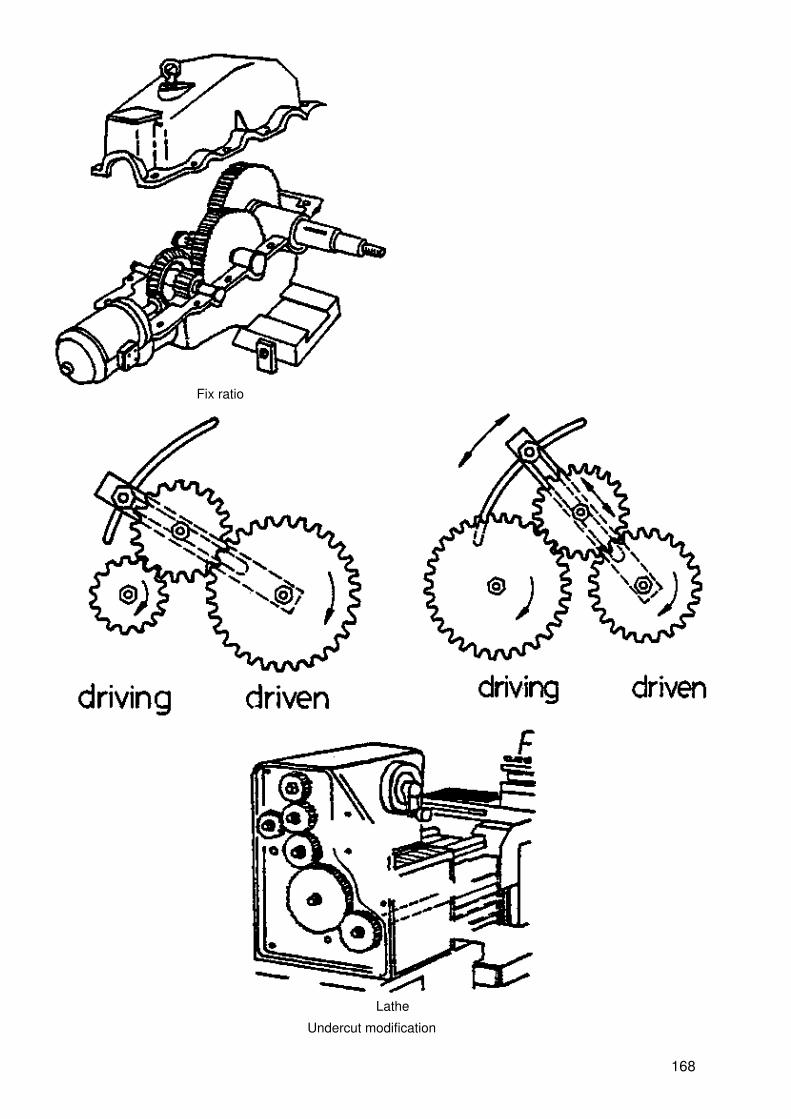
Fix ratio
Lathe
Undercut modification
168

1. Normal gear
gear tooth is normal
2. Undercut gear with less than 14 teeth
gear tooth is weakened
3. Undercut is avoided by shifting the pitch circle
gear tooth is strong
169

Types and Usage of Gear
Spur gear
Feed Gear Box In Lathe
170
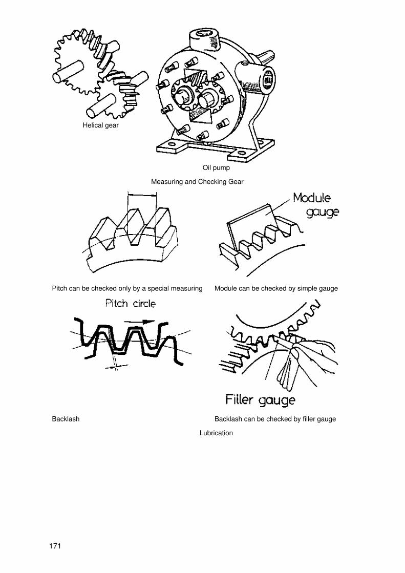
Helical gear
Oil pump
Measuring and Checking Gear
Pitch can be checked only by a special measuring Module can be checked by simple gauge
Backlash Backlash can be checked by filler gauge
Lubrication
171

By hand
Drop oil
Oil bath
Oil pump
Bevel gear
hand driller
172

Worm gear
Dividing head
Rack and pinion
Driller
173

Non working position Working position
Driving key gear
Planetary gear
Repairing a tooth broken gear
tooth is brokenFile
174

Drill the holes
Bolt
Weld
Gauge
7. Roller bearings
Objectives
I. Purpose and basic function
1.
a) Describe the difference of friction in a roller bearing and in a bush bearingb) Describe the position of a shaft and the friction coefficient of bush bearingand roller bearing when revolution is changing.
2.
a) Name the parts of roller bearingb) Describe the property and the function of the components of a rollerbearing
II. Type and design
3. Show the difference between deep groove ball bearing and cylindrical roller bearingaccording to
− direction of load− contact area
4. Give reasons for the selection criteria of deep groove ball bearing and needle bearingaccording to
− quantity of load− outer diameter of the bearing
5. Compare load capacity of thrust ball bearing, cylindrical roller bearing & tapered rollerbearing
175

6. Explain why a spherical roller bearing is chosen when the shaft is misaligned.
7.
a) Explain the load capacity of the following bearings:
deep groove ball bearing, cylindrical roller bearing, taperedroller bearing, needle roller bearing, thrust ball bearing,spherical roller bearing
b) Name the above mentioned bearings
III. Assembly, repair and maintenance
8. Explain why one of two bearings must be arranged floating.
9. Describe two different ways of realizing floating arrangement.
10. Explain the difference between point load and circumferential load at the inner and outerrace when direction of load is constant,
11. Explain why a tight fit is used when the load at the race is circumferential and a loose fitfor point load.
12. Explain why interference fit is needed on bearing ring which is subjected to rolling force,and transition fit for the ring which is subjected to stationary point load.
13. Explain reason for exerting force directly on either inner or outering of bearing whendismounting it.
14. Explain the use of tools for mounting and dismounting bearings
15. Explain reasons for provision of clearance between balls and race of rolling bearings.
16. Explain techniques of clearance adjustment of rolling bearings by back to back and tapersleeve methods.
17. Tell how bearings are mounted to shaft or housing by means of warming and coolingtechniques.
18.
a) Tell 5 methods in lubricating bearings with oil or grease,b) Give reasons for the use of oil or grease or lubricating medium forbearings.
19. Explain how to mount seal to shaft and housing.
20. Explain at least 3 methods in diagnosing faults of bearings during its operation.
Information sheet
1. Purpose and basic function
1.1 Comparison roller bearings − bush bearings
176

n = revolution per minute (1/min)v = speed (m/min)µ = coefficient of friction
1.2 Types and design
2. Types and design
2.1 Deep groove ball bearing and cylindrical roller bearing − direction and capacity of load, contact surface
Name Load capacity contact areas
load no load
177

Deep grooveball bearing
can support more radial than thrust load pressure area is apoint
pressure area is anellipse
Cylindricalroller bearing
can support only radial load pressure area is a line pressure area is asquare
2.2 Deep groove ball bearing and needle bearing − direction of load and outer diameter
Deep groove ball bearing Needle roller bearing
diameter of the shaftsare equal
outer diameter big small
178

width of bearing small big
radial load big very big
2.3 Thrust ball bearing and tapered roller bearing − direction of load
Type of bearing direction of load
Thrust ball bearing axial (thrust)
Cylindrical roller bearing radial
Tapered roller bearing axial and radial
2.4 Spherical roller bearing
Cylindrical roller bearing Spherical roller bearing
The load is concentrated at one point, the bearingwill be destroyed soon.
Remedy: Using a spherical roller bearing, themisaligning should not be bigger than 4°.
2.5 Rolling bearings and their application electric motor
Type of bearing Amount and direction ofload
179

1.
2.
3.
180

4.
5.
6.
3. Assembly, repair and maintenance
3.1 Floating bearing
181

When the temperature increases, the shaft extends. If this is not possible, the bearing will be destroyed.
3.2 Point load and circumferential load constant load
Shaft and inner ring are rotating Housing and outer ring are rotating
Load on thebearing races
inner ring: alongcircumference
outer ring:point load
inner ring:point load
outer ring: alongcircumference
application
Influence of point load and circumferential load to the fit of a bearing:
182

fit reason
inner ring:circumferential load
tight protection against twisting of the wheel inthe inner ring, which destroys the wheel
outer ring: point load loose simple assemble the outer ring is fixed bythe cover.
inner ring: point load tight simple assemble the inner ring is fixed bya nut.
outer ring:circumferential load
loose protection against twisting of the outerring in the housing which destroys thewheel.
3.3 Assembling by sleeve
When assembling, the force must act on theouter ring.
When the force acts on the inner ring, the race way will bedamaged.
183

When assembling, the force must act on theinner ring.
when the force acts on the outer ring, the race way will bedamaged.
Note: A sleeve is used for mounting small bearings.
3.4 Disassembling by puller
When dismounting, the force directly acts at the tightly fit ring.
The bearing is dismounted by a puller and a puller plate. When dismounted without puller plate, the race way and rolling elements will bedamaged.
3.5 Clearance of roller bearings
− mounted bearings should have very low clearance. However, they must have some toenable the expansion from getting warm.
184

− generally fits of bearings (e.g. shaft J5, housing I6) ensure sufficient clearance.
Assembly of bearings
back to back arrangement sleeve mounted bearing
Smallbearings
Clearance value can be foundin the machine manual. For carwheel: tighten the nut, thenloose it ca. 1/12 round.
Correctly tightened, the outer race must turn easily, butthere must be some resistance to swivel it.
big bearings check clearance with fillergauge
check clearance with filler gauge
The clearance can be found inthe machine manual.
The clearance will be found in the table below.
Inner diameter of bearing minimum clearance
30 − 40 0.015
40 − 50 0.020
185

50 − 85 0.025
3 − BO 0.025
80 − 100 0.035
100 − 120 0.050
3.6 Assembling by warming and cooling
Assembling by warming
− before assembling
− assembling after warming up in oil
− the flash point of the. oil should be higher than250° C.
− after assembly cooling to room temperature
− drive the bearing with mounting sleeve to avoidgap "s"
Assembling by cooling
186

− before assembling − assembling after cooling in ice.
− cooling the bearing with dry ice at −20°C
− after assembly warming up to room temperature
drive the bearing with sleeve to avoid gap "s"
Note: only big bearings are mounted by warming or cooling.
3.7 Lubrication systems
picture lubrication method
grease lubrication
187

splash lubrication
drip feed lubrication
pressure oil lubrication
grease filling for lifetime
188

3.8 Sealings
assembled in the correct way assembled in the wrong way
Note: A fine shaft−surface increases working life of the sealing
3.9 Inspection of defect roller bearings during work
Sound−check
When the bearing runs noisily, it might be damaged.
Temperature−check
189

When the bearing gets hot, it might be damaged.
Odour−check
When the bearing gets very hot, the grease starts burning and smelling.
Activity sheet
2.1 Direction and capacity of load
Activity: Discuss the following problems in groups of 4 to 5 students:
There are two directions of load:
− radial load−thrust load
1.
− The load in picture a) and b) is radial/thrust.− Compare the load capacity and give reasons:
190

____________________________________________________________________________________________________________________
2.
− The load in picture a) and b) is radial/thrust.− Compare load capacity and give reasons:
____________________________________________________________________________________________________________________
3.
a)
b)
191

Show the direction and capacity of load by
filling in and givereasons
__________________________________________________________________________________________________________
Remark:
= cannot support any load
= can support low load
= can support moderate load
= can support high load
4. What has to be considered when using the bearings of task No. 3?
__________________________________________________________________________________________________________
2.5 Roller bearings and their application
1. Choose the appropriate bearings for the electric motor.
192

1 ___________2 ___________
2. Choose the appropriate bearings for the lathe dog.
1 ___________2 ___________3 ___________
Task sheet
1.1.1 Which point (1, 2, 3 or 4) is related to the drawings at the right side? Insert the right numbers.
193

1.1.2 At low rpm the friction of a bush bearing is high/constant/low
1.1.3 At low rpm the friction of a roller bearing is high/constant/low
1.1.4 Centering of a roller bearing/bush bearing is independent from rpm.
1.2.1 Name the numbered parts in the picture.
1.2.2 Put the numbers in the appropriate square.
race of the rolling element
keeps distance between rolling elements
reduces friction between inner and outer race
1.2.3 Which part of the bearing is not necessary hardened and polished − inner race/outer race/rollingelement/cage?
194
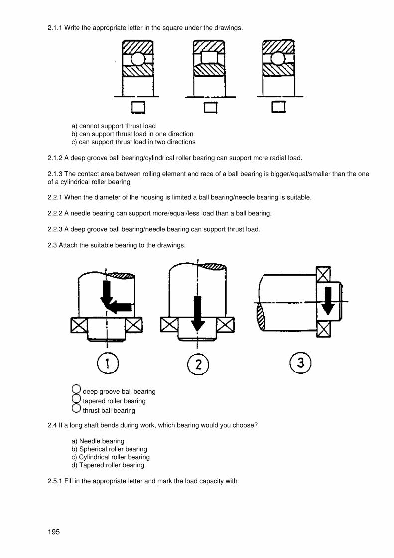
2.1.1 Write the appropriate letter in the square under the drawings.
a) cannot support thrust loadb) can support thrust load in one directionc) can support thrust load in two directions
2.1.2 A deep groove ball bearing/cylindrical roller bearing can support more radial load.
2.1.3 The contact area between rolling element and race of a ball bearing is bigger/equal/smaller than the oneof a cylindrical roller bearing.
2.2.1 When the diameter of the housing is limited a ball bearing/needle bearing is suitable.
2.2.2 A needle bearing can support more/equal/less load than a ball bearing.
2.2.3 A deep groove ball bearing/needle bearing can support thrust load.
2.3 Attach the suitable bearing to the drawings.
deep groove ball bearing tapered roller bearing thrust ball bearing
2.4 If a long shaft bends during work, which bearing would you choose?
a) Needle bearingb) Spherical roller bearingc) Cylindrical roller bearingd) Tapered roller bearing
2.5.1 Fill in the appropriate letter and mark the load capacity with
195

Name of bearing ball cylindrical tapered needle spherical thrust ball
letter
thrust load capacity
radial load capacity
2.5.2 Attach the applications 1, 2 and 3 to the appropriate bearing.
3.1.1 Mark the correct reason for floating arrangement with ?.
a) The shaft rotates easily.b) It is simple to assemble and disassemble.c) It prevents damage of the bearing.
3.1.2 Which of the following applications is wrong?
196

3.1.3 A ball bearing can act as floater by
a) sliding between inner race and shaftb) sliding between inner race and roller elementc) sliding between outer race and roller elementd) sliding between outer race and housing
3.1.4 A cylindrical roller bearing can act as floater by
a) sliding between inner race and shaftb) sliding between inner race and roller elementc) sliding between outer race and roller elementd) sliding between outer race and housing
3.2.1 The load on a turning race of a bearing is called point/circumferential load
3.2.2 When the inner race is fixed and the outer race turns, point load occurs at the inner/outer race.
3.2.3
197

When lifting the block W, circumferential load occurs at the inner/outer race of the bearing.
3.2.4
At the bearing circumf. load occurs at the inner/outer ring; therefore, a loose fit must be chosen for theinner/outer ring.
3.2.5
At the bearing circumferential load occurs at the inner/outer ring; therefore, a tight fit must be chosen for theinner/outer ring.
3.2.6
198

Such damage is a result of the assembling method
a) b) c) d)
a) b) c) d)
3.4 Relate the tools a, b, c, d to the appropriate examples 1, 2, 3, 4.
a) b) c) d)
1) 2) 3) 4)
199

3.5.1 Clearance of roller bearings is necessary
a) to provide the rolling elements with lubricantb) to provide sufficient space for heat expansionc) for easy and comfortable assembling
3.5.2 A roller bearing runs loud when there is no/too much/too low clearance.
3.5.3 A bearing will not have sufficient clearance when it is assembled at both rings by tight fit/loose fit.
3.5.4 Back to back assembled bearings for car wheels must be tightened and released for 1/12, 1/3, 1 round.
3.5.5 Checking of radial clearance by swiveling the outer ring will be done with
a) small bearings, which are assembled back to backb) big spherical roller bearingsc) small spherical roller bearingsd) big bearings, which are assembled back to back
3.5.6 Clearance of bearing is not related to working−temperature/direction of load/size of bearing.
3.6.1 Mounting of bearings with shaft by heat will be done by __________
3.6.2 Mounting of bearings with housing by cooling will be done by __________
3.7.1 Write down 3 methods of lubricating a bearing
1.__________ 2. _________ 3.____________
3.7.2 Bearings working at high revolutions and high temperature should be lubricated by
a) splashb) drip feedc) pressure oild) grease
3.8.1 In which picture is the scaling mounted correctly?
200

a) b) c)
3.8.2 The correct assembly of a seal should consider flow direction of lubricant/direction of load
3.9 Simple methods to check a working bearing are
1. ________________________________2. ________________________________3. ________________________________
Solutions
1.1.1
a) 3
b) 1
c) 4
d) 2
1.1.2 high
1.1.3 constant
1.1.4 roller bearings
1.2.1
rolling elements inner ringcage
1.2.2
1.2.3 cage
2.1.1
b a c
2.1.2 cylindrical roller bearing
201

2.1.3 smaller than
2.2.1 needle roller bearing
2.2.2 more than
2.2.3 deep groove ball bearing
2.3
2.4
c) spherical roller bearing
2.5.1
Name of bearing ball cylindrical tapered needle spherical thrust
letter b e a f c d
thrust load capacity ? ? ?
radial load capacity ? ? ? ? ?
2.5.2
3.1.1 c) ?
3.1.2 a)
3.1.3 d)
3.1.4 c)
3.2.1 circumferential load
3. 2. 2 inner race
3.2.3 outer race
3.2.4 inner ring/outer ring
3.2.5 inner ring/inner ring
3.3 b)
3.4
202

a) 3
b) 1
c) 4
d) 2
3.5.1 b)
3.5.2 too much
3.5.3 tight fit
3.5.4 1/12
3.5.5 c)
3.5.6 direction of load
3.6.1 warning the bearing in oil
3.6.2 cooling the bearing in dry ice
3.7.1
− grease lubrication− drip feef lubrication− grease filling for life time− splash lubrication− pressure oil lubrication
3.7.2 c)
3.8.1 b)
3.8.2 flow direction of lubricant
3.9
1. sound−check2. temperature−check3. odour−check
Feature of Bearing
203

Bush bearing Roller bearing
Component of roller bearing
204

205

Cylindrical roller bearingSpherical roller bearing
FLOATING BEARING
CIRCUMFERENTIAL LOAD AND POINT LOAD
206

Fit
Inner ringcircumferential load
tight
Outer ringpoint load
loose
Inner ringpoint load
loose
Outer ringcircumferential load
tight
POINT LOAD AND CIRCUMFERENTIAL LOAD
Shaft and inner ring are rotating Housing and outer ring are rotating
Load on thebearing races
inner ring circumferenceload
outer ring pointload
inner ring pointload
outer ringcircumference load
Bearing Assembly
207

Bearing Disassembly
208

CLEARANCE OF ROLLER BEARING
ADJUSTMENT CLEARANCE OF BEARING
209

Back to back arrangementSleeve mounted bearing
Filler gauge
Small bearing Big bearingSmall bearing
LUBRICATION METHOD
210

Splash lubrication
Drip feed lubrication
Grease lubrication
Pressure oil −lubrication
Grease filling for lifetime
SEAL ASSEMBLY
211
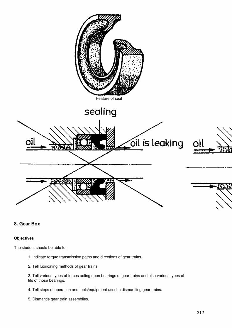
Feature of seal
8. Gear Box
Objectives
The student should be able to:
1. Indicate torque transmission paths and directions of gear trains.
2. Tell lubricating methods of gear trains.
3. Tell various types of forces acting upon bearings of gear trains and also various types offits of those bearings.
4. Tell steps of operation and tools/equipment used in dismantling gear trains.
5. Dismantle gear train assemblies.
212

6. Name various parts of gear train assemblies, their materials and sizes.
7. Inspect conditions of those dismantled gear train assemblies.
8. Tell functions of various parts of gear train assemblies.
9. Measure and specify dimensions of shafts and bores.
10. Specify required surface finish of shafts
11. Tell steps of operation and tools/equipment used in reassembling gear trains.
12. Reassemble gear train assemblies.
13. Measure and calculate various dimensions of a gear.
14. Interprete specifications given on a name plate of a gear box.
15. Determine various datum of a gear box from a given table.
16. Calculate spindle speeds and gear ratios of a gear box.
17. Calculate power and torque of a gear box.
1. Torque transmission and direction of load
Indicate torque transmission paths (by thick lines) and their directions (by arrows) of the gear box, on both,pictures.
Example:
Note:
Tail of the arrow is
Head of the arrow is
213

From the pictures in page 1; please answer the following question
1.1 Lubrication system
The lubrication of this gear box is of:− gravity/pump/immerse/manual−type
2. Type, load and fit of bearing
Please complete the table
BearingNo.
Types ofbearing
Load is stationaryat...
Load is distributedover...
Interference fitat...
Transition fitat...
7
8
18
21
3−10. Disassembling the gear box
3. Shaft 4/Shaft 15 must be removed first because worm gear and thread are going to jam.
Wait! Allow the instructor to have a good check before attempting next.
4. Write down part numbers and required tools/equipment to be used in dismantling assemblies attached tothe gear.
Sequence of Operations Part No. Tools/equipmentused
1 14
214

2
3
4
5
6
7
8
9
10
5. Shaft 15 can be removed from the housing by way of the cover plate−16 or 20/or 16 and 20
6. Write down the steps in removing components assembled to the shaft 15 after it has been removed fromthe housing.
Sequence Part No. Tools/equipment
1
2
7. Write down the steps for removing components assembled to the shaft 4 after it has been removed fromthe housing.
Sequence Part No. Tools/equipment
1
2
3
8. Which picture shows a correct bearing dismounting,?
Wait! Allow the instructor to have a check before attempting next
Direction:
9. You should check and prepare tools/equipment as listed in the tool box.
10. Dismantle components of the gear box in correct sequence; place the dismantled components in separatesets in good orders on the equipment tray
Note: Do not separate the following parts: 2 and 3, 9 & 10 and 5, 16 and 17, 13 and 20. Great care must beexercised while working. Consult your instructor any time if you may have problem.
215

11. Identifying the part of a gear box
After you have completed the task, write down details of components into the table on page 4.
Quantity Name of part Material Part No. Standard size Condition
Good Poor
1 Housing Cast iron 1 ____
2 ____
3 ____
4 ____
5 ____
6
7
8
9 ____
10 ____
11
12
13 ____
14 ____
15 ____
16 ____
17 ____
18
19
20 ____
21
22
Note: Count the number of teeth of both, the worm wheel and the worm thread and note themalso.
12. Function of the parts
Match the functions in a, b, c, d to related components given on the right, based on the gear box shown onpage 1.
(A single component may have more than one function)
Functions Components (part No.)
a. To transmit torque 1. Housing (1)
216

b. To resist load 2. Worm wheel (2)
c. To hold components 3. Worm hub (3)
d. To prevent oil leakage 4. Output shaft (4)
5. Cover plate (5)
6. Socket screw (6)
7, Ball bearing (7)
8. Seal (9)
9. O−ring (10)
10. Key (12)
11. Input shaft (15)
12. Cover plate (16)
13. Tapered roller bearing (18)
13. Measuring dimensions of shafts and bores
Measure and write down dimensions of shafts and bores with necessary symbols of required fits.
Transition fit Bore H8 Shafth6
Interference fit Bore M7 Shaft m5
217

Make a tick for required surface finishes into theappropriate
Surface finish
?
??
???
14−16. Assembling the gear box
14. You are required to complete this exercise before attempting reassemble the gear box.
14.1 In reassembling the gear box − the output shaft/the input shaft − must be mounted firstly into thehousing.
14.2 Write down the sequence of operations in reassembling the gear box, onto the table below − (See thepicture, page 1)
Sequence of operation Part No. Mounted to part No Tools/equipment
1 12 4 Plastic head hammer
2
3
4
218

5
6
7
8
9
10
11
12
13
14
15
16
17
18
15. Which picture: shows correct bearing mounting
Wait! Allow the instructor to have a look before doing next
16. You are required to reassemble the gear box. Obey the following instructions
− Smear components to be reassembled with oil− Report any damaged component to the instructor before mounting, particularly bearingsand seals.
219

− Use mounting sleeves to drive bearings
After you have completed the gear box reassemble, please continue the next exercise.
17. Dimension of a gear
You are required to determine various sizes and tolerances of the spur gears below, by using the standard fitsas already shown on page 6.
17.1
Number of gear teeth (z) =
Module (m) =
Depth of gear teeth(h) =
Formulae
d = m.z
da = d + 2m
17.2
220

Number of gear teeth (z) =
Module (m) =
Depth of gear teeth(h) =
17.3 Centre distance of a gear train set(a) = _________
18. RMP and gear ratio calculations
18.1 Single gear drive
18.1.1 Spur gear
i = Gear ration1 = RMP of driving gearn2. = RMP of follower gearz1 = number of teeth of driving gearz2 = number of teeth of follower gear
18.1.2 Worm gear
221

g = number of pitches
18.2 Multiple gear drive
i1 = ratio of gear drive 1i2 = ratio of gear drive 2i3 =.....in = ratio of gear drive ni = joint ratio of all gear drives
i = i1 i2........ in
19. Power, torque and efficiency of a gear box
19.1 Single gear drive
P = powerT = torquen = efficiency
222

19.2 Multiple gear drive
n1 = efficiency of gear drive 1n2 = efficiency of gear drive 2n3 = efficiency of gear drive 3nn = efficiency of gear drive nn = joint efficiency of all gear drive;
n(...) = n1·n2·n3·....·nn
20−21. Name plate
20. Read the name plate of the gear box and fill in the missing datas in the table below.
223

Note: The name plate is of JIS standard which is different from DIN.
PA 18 means
1: 10 means
M 40607 means
Bellpony means
Wait! Have the instructor check before doing next
21. Based on the name plate and the table of page 13, if the required output speed is 120 min−1, what will bethe followings?
21.1 The input speed = ______________ min−1
21.2 Input power = ______________ kw
21.3 Output torque = ______________ kg−m
or = ______________N−m
(1 kg = 9.81 N)
Selection table
PR.PA.PO.PF types
Type Input Speed(rpm)
Ratio 1/10 1/15 1/20 1/25 1/30 1/40 1/50 1/60
12 1800 Input (KW) 0.82 0.63 0.48 0.35 0.41 0.31 0.24 0.20
Output Torque(kg−m)
3.59 3.99 3.94 3.33 4.50 4.50 3.73 3.59
1500 Input (KW) 0.74 0.56 0.43 0.31 0.37 0.29 0.22 0.18
Output Torque(kg−m)
3.87 4.22 4.21 3.52 4.78 4.80 4.03 3.70
1200 Input (KW) 0.65 0.50 0.37 0.28 0.33 0.25 0.19 0.16
Output Torque(kg−m)
4.23 4.58 4.43 3.85 5.2 5.14 4.28 4.01
1000 Input (KW) 0.58 0.45 0.33 0.25 0.30 0.23 0.18 0.15
Output Torque(kg−m)
4.44 4.94 4.76 4.05 5.46 5.49 4.63 4.32
800 Input (KW) 0.53 0.39 0.29 0.22 0.27 0.20 0.16 0.13
224

Output Torque(kg−m)
5.00 5.23 5.16 4.40 6.07 5.85 4.89 4.54
600 Input (KW) 0.43 0.32 0.25 0.19 0.22 0.17 0.13 0.11
Output Torque(kg−m)
5.35 5.7 5.74 4.79 6.44 6.32 5.23 4.85
15 1800 input (KW) 1.31 1.00 0.72 0.54 0.66 0.48 0.37 0.32
Output Torque(kg−m)
5.78 6.33 5.82 5.14 7.33 6.55 5.73 5.75
1500 Input (KW) 1.17 0.90 0.64 0.48 0.58 0.42 0.34 0.29
Output Torque(kg−m)
6.15 6.83 6.19 5.43 7.73 6.92 6.31 6.06
1200 Input (KW) 1.04 0.79 0.56 0.43 0.53 0.39 0.30 0.25
Output Torque(kg−m)
6.78 7.36 6.64 5.90 8.46 7.61 6.58 6.43
1000 Input. (KW) 0.93 0.71 0.51 0.39 0.47 0.35 0.27 0.23
Output Torque(kg−m)
7.23 7.88 7.14 6.32 8.84 8.00 7.05 6.88
800 Input (KW) 0.82 0.62 0.44 0.34 0.42 0.31 0.24 0.21
Output Torque(kg−m)
7.86 8.49 7.57 6.72 9.67 8.58 7.51 7.50
600 Input (KW) 0.67 0.51 0.39 0.29 0.36 0.26 0.20 0.18
Output Torque(kg−m)
8.54 9.04 8.56 7.42 10.50 9.35 8.07 7.90
18 1800 Input (KW) 2.76 2.08 1.54 1.21 1.36 1.01 0.79 0.77
Output Torque(kg−m)
12.28 13.37 12.87 12.34 15.33 14.66 13.87 14.14
1500 Input (KW) 2.47 1.90 1.39 1.08 1.21 0.90 0.73 0.70
Output Torque(kg−m)
13.10 14.46 13.84 13.13 16.25 15.48 15.09 15.11
1200 Input (KW) 2.20 1.66 1.21 0.97 1.08 0.80 0.64 0.61
Output Torque(kg−m)
14.46 15.65 14.85 14.39 17.77 16.88 16.01 16.00
1000 Input (KW) 1.96 1.50 1.10 0.85 0.99 0.73 0.59 0.57
Output Torque(kg−m)
15.33 16.74 15.96 15.05 19.02 17.90 17.19 17.20
800 Input (KW) 1.71 1.30 0.95 0.75 0.87 0.64 0.52 0.49
Output Torque(kg−m)
1.6.58 17.88 16.92 16.23 20.38 19.19 18.32 18.04
600 Input (KW) 1.43 1.08 0.83 0.63 0.73 0.55 0.42 0.42
Output Torque(kg−m)
18.21 19.40 19.14 17.80 22.07 20.93 19.37 19.46
22 1800 Input (KW) 3.80 2.95. 2.06 1.68 1.89 1.35 1.10 0.90
225

Output Torque(kg−m)
17.0 19.0 17.1 17.0 21.8 19.5 19.1 17.1
1500 Input (KW) 3.41 2.65 1.88 1.49 1.70 1.23 1.02 0.83
Output Torque(kg−m)
18.2 20.3 18.4 17.9 23.00 20.6 20.7 18.3
1200 Input (KW) 3.07 2.30 1.65 1.32 1.43 1.12 0.88 0.73
Output Torque(kg−m)
20.3 21.9 19.9 19.6 24.8 22.9 21.8 19.5
1000 Input (KW) 2.75 2.08 1.47 1.20 1.37 0.98 0.80 0.66
Output Torque(kg−m)
21.7 23.4 21.1 21.0 26.9 23.8 23.3 20.7
800 Input (KW) 2.42 1.83 1.31 1.03 1.21 0.88 0.71 0.58
Output Torque(kg−m)
23.5 25.4 23.0 22.2 28.9 25.6 24.8 21.9
600 Input (KW) 2.03 1.52 1.11 0.88 1.02 0.74 0.59 0.51
Output Torque(kg−m)
26.0 27.5 25.3 24.5 31.3 27.6 26.6 23.8
25 1800 Input (KW) 6.91 5.29 3.89 3.03 3.39 2.48 1.95 1.61
Output Torque(kg−m)
31.3 34.6 33.5 31.9 39.9 38.1 35.9 34.3
1500 Input (KW) 6.24 4.70 3.53 2.69 3.01 2.24 1.78 1.46
Output Torque(kg−m)
33.5 36.5 36.0 33.6 41.9 40.4 38.7 36.7
1200 Input (KW) 5.58 4.17 3.06 2.37 2.67 2.02 1.54 1.26
Output Torque(kg−m)
37.1 39.9 38.7 36.5 45.1 44.9 40.9 38.8
1000 Input (KW) 4.98 3.79 2.75 2.14 2.43 1.78 1.39 1.16
Output Torque(kg−m)
39.5 43.2 41.3 39.1 48.7 46.6 43.4 41.7
800 Input (KW) 4.31 3.28 2.43 1.85 2.14 1.57 1.23 1.00
Output Torque(kg−m)
42.5 46.2 45.0 41.5 52.6 50.2 46.7 43.8
600 Input (KW) 3.65 2.78 2.05 1.57 1.81 1 32 1 03 0.85
Output Torque(kg−m)
47.2 51.1 49.5 46.0 57.4 54.1 50.0 47.2
30 1800 Input (KW) 10.76 3.32 5.92 4.93 5.23 3.76 3.10 2.55
Output Torque(kg−m)
48.9 55.0 50.4 53.1 62.8 56.8 59.6 54.8
1500 Input (KW) 9.88 7.38 5.35 4.36 4.70 3.45 2.83 2.32
Output Torque(kg−m)
53.5 57.9 54.0 55.6 66.4 61.0 63.7 58.7
1200 Input (KW) 8.77 6.58 4.72 3.81 4.17 3.06 2.46 2.03
226

Output Torque(kg−m)
58.9 63.7 58.7 60.2 72.2 66.1 68.1 62.1
1000 Input (KW) 7.68 5.93 4.20 3.47 3.79 2.82 2.19 1.80
Output Torque(kg−m)
61.3 68.1 61.6 65.1 76.9 70.7 71.6 65.4
800 Input (KW) 6.82 5.13 3.69 2.99 3.37 2.45 1.94 1.59
Output Torque(kg−m)
67.6 73.0 66.7 69.1 83.9 75.2 77.3 69.5
600 Input (KW) 5.67 4.38 3.17 2.51 2.79 2.06 1.61 1.34
Output Torque(kg−m)
74.2 81.5 74.8 76.0 90.0 81.3 82.5 74.9
35 1800 Input (KW) 15.00 11.78 8.49 6.73 7.31 537 4.21 3.42
Output Torque(kg−m)
68.8 79.0 74.8 72.9 90.2 86.0 82.0 76.5
1500 Input (KW) 13.91 10.43 7.82 5.98 6.56 4.88 3.80 3.11
Output Torque(kg−m)
76.2 83 2 82.0 77.0 95.4 92.2 87.0 820
1200 1000 Input (KW) 12.23 0.17 6.78 5.19 5.81 430 3.36 2.71
Output Torque(kg−m)
83.2 90.5 87.5 82.5 103 99.0 93.0 36.7
Input (KW) 10.89 8.36 0.05 4.66 5.22 3.88 2.08 2.41
Output Torque(kg−m)
88.1 97.8 93.1 88.1 109 106 98.0 91.4
800 Input (KW) 9.59 7.22 5.28 1.12 4.07 3.35 2.63 2.12
Output Torque(kg−m)
96.4 104 100 95.8 120 112 106 97.0
600 Input (KW) 8.03 6.15 4.47 3.45 3.86 2.82 2.20 1.78
Output Torque(kg−m)
106 117 111 104 129 122 114 104
22. Calculation exercises
Based on the information on pages 4 and 9, determine the valves for z1. z2, z3, and z4 and write it down ontothe appropriate blocks
227

22.1Demonstrateyourcalculations forvarious valvesonto the leftcolumn andwrite theobtainedresults onto theright column.
i1 = −
i2=
i(...) =
n2 =
n3 =
n4 =
Demonstrateyourcalculationson the leftcolumn andwrite down theobtainedresults on theright column.
228

T1 =
T2 =
T3 =
T4 =
P4 =
22.2Suppose, theefficiencies ofthe geartrains
,
,determine thefollowings:
T1 =
T2 =
T3 =
T4 =
P2 =
P3 =
P4 =
Tools and equipment
Number Tools
1 Puller plate
1 Small puller
1 Plastic hammer
1 Hexagon socket screw wrench No. 6
1 Hexagon socket screw wrench No. 9
1 Pliers
1 Ring spanner No. 16−17
1 Wrench No. 8 − 9
1 Wrench No. 5/8 " − 3/4 "
1 Small flat standard screw driver
1 Middle flat standard screw driver
1 Large flat standard screw driver
2 Sleeve
1 Support, Pipe
1 Cylindrical guide
229

1 Puller support (Brass)
1 Gear Tooth gauge (MP)
1 pair Wood for support jaws vice
Note: The presses, vice and vernier are prepared by the teacher.
230