
EN / FCAN-01 CANopen adapter module user's manual
172
Options for ABB drives, converters and inverters User’s manual FCAN-01 CANopen adapter module
Transcript of EN / FCAN-01 CANopen adapter module user's manual
Options for ABB drives, converters and inverters
User’s manualFCAN-01 CANopen adapter module

List of related manualsSee section Related manuals on page 16.
6. Start-up
User’s manualFCAN-01 CANopen adapter module
3AFE68615500 Rev EENEFFECTIVE: 2012-04-02
© 2012 ABB OyAll Rights Reserved.
1. Safety
Table of contents
4. Mechanical installation
5. Electrical installation

Table of contents 5
Table of contents
1. SafetyWhat this chapter contains . . . . . . . . . . . . . . . . . . . . . . . . . . . . . 11Use of warnings . . . . . . . . . . . . . . . . . . . . . . . . . . . . . . . . . . . . . 12Safety in installation . . . . . . . . . . . . . . . . . . . . . . . . . . . . . . . . . . 13
2. About the manualWhat this chapter contains . . . . . . . . . . . . . . . . . . . . . . . . . . . . . 15Applicability . . . . . . . . . . . . . . . . . . . . . . . . . . . . . . . . . . . . . . . . 15Compatibility . . . . . . . . . . . . . . . . . . . . . . . . . . . . . . . . . . . . . . . 15Target audience . . . . . . . . . . . . . . . . . . . . . . . . . . . . . . . . . . . . . 15Purpose of the manual . . . . . . . . . . . . . . . . . . . . . . . . . . . . . . . . 16Related manuals . . . . . . . . . . . . . . . . . . . . . . . . . . . . . . . . . . . . 16Before you start . . . . . . . . . . . . . . . . . . . . . . . . . . . . . . . . . . . . . 17Contents . . . . . . . . . . . . . . . . . . . . . . . . . . . . . . . . . . . . . . . . . . . 18Terms and abbreviations used in this manual . . . . . . . . . . . . . . 19
Terms . . . . . . . . . . . . . . . . . . . . . . . . . . . . . . . . . . . . . . . . . 19CANopen abbreviations . . . . . . . . . . . . . . . . . . . . . . . . . . . . 20
3. Overview of the CANopen protocol and the FCAN-01 adapter moduleWhat this chapter contains . . . . . . . . . . . . . . . . . . . . . . . . . . . . . 23CANopen protocol . . . . . . . . . . . . . . . . . . . . . . . . . . . . . . . . . . . 23Topology of the CANopen link . . . . . . . . . . . . . . . . . . . . . . . . . . 24FCAN-01 CANopen adapter module . . . . . . . . . . . . . . . . . . . . . 25Layout of the adapter module . . . . . . . . . . . . . . . . . . . . . . . . . . 26
4. Mechanical installationWhat this chapter contains . . . . . . . . . . . . . . . . . . . . . . . . . . . . . 27Delivery check . . . . . . . . . . . . . . . . . . . . . . . . . . . . . . . . . . . . . . 27Mounting the adapter module . . . . . . . . . . . . . . . . . . . . . . . . . . 28
5. Electrical installationWhat this chapter contains . . . . . . . . . . . . . . . . . . . . . . . . . . . . . 29
6 Table of contents
General cabling instructions . . . . . . . . . . . . . . . . . . . . . . . . . . . . 29Connecting the module to the CANopen network . . . . . . . . . . . 30Bus termination . . . . . . . . . . . . . . . . . . . . . . . . . . . . . . . . . . . . . 31AC and DC parameters for the CANopen network . . . . . . . . . . . 32
Bus cable and termination resistors . . . . . . . . . . . . . . . . . . . 32
6. Start-upWhat this chapter contains . . . . . . . . . . . . . . . . . . . . . . . . . . . . . 35Drive configuration . . . . . . . . . . . . . . . . . . . . . . . . . . . . . . . . . . . 35
CANopen connection configuration . . . . . . . . . . . . . . . . . . . 36Data transfer rates supported. . . . . . . . . . . . . . . . . . . . . 36FCAN-01 configuration parameters – group A (group 1) 37FCAN-01 configuration parameters – group B (group 2) 51FCAN-01 configuration parameters – group C (group 3) 54Additional information on the virtual address areaallocation . . . . . . . . . . . . . . . . . . . . . . . . . . . . . . . . . . . . 57
Control locations . . . . . . . . . . . . . . . . . . . . . . . . . . . . . . . . . 58Starting up ACS355 drives . . . . . . . . . . . . . . . . . . . . . . . . . . . . . 58
Parameter setting examples – ACS355 . . . . . . . . . . . . . . . . 59CiA 402 vl velocity mode with default PDO mapping . . . 59Speed and torque control using ABB Drivescommunication profile with parameter-configured PDOmapping . . . . . . . . . . . . . . . . . . . . . . . . . . . . . . . . . . . . . 61
Starting up ACSM1 drives . . . . . . . . . . . . . . . . . . . . . . . . . . . . . 64Parameter setting examples – ACSM1 . . . . . . . . . . . . . . . . 66
Using position control with the CiA 402 Profile Position mode. . . . . . . . . . . . . . . . . . . . . . . . . . . . . . . . . . . . . . . . 66
Starting up ACS850 drives . . . . . . . . . . . . . . . . . . . . . . . . . . . . . 69Parameter setting examples – ACS850 . . . . . . . . . . . . . . . . 70
CiA 402 Velocity mode with default PDO mapping . . . . 70ABB Drives communication profile with parameter-configured PDO mapping . . . . . . . . . . . . . . . . . . . . . . . . 72
Starting up ACS880 drives . . . . . . . . . . . . . . . . . . . . . . . . . . . . . 75Parameter setting examples – ACS880 . . . . . . . . . . . . . . . . 76
CiA 402 Velocity mode with default PDO mapping . . . . 76Configuring the master station . . . . . . . . . . . . . . . . . . . . . . . . . . 78

Table of contents 7
EDS files . . . . . . . . . . . . . . . . . . . . . . . . . . . . . . . . . . . . . . . 78Configuring an ABB AC500 PLC . . . . . . . . . . . . . . . . . . . . . 79
7. Communication profilesWhat this chapter contains . . . . . . . . . . . . . . . . . . . . . . . . . . . . . 87Communication profiles . . . . . . . . . . . . . . . . . . . . . . . . . . . . . . . 87CANopen device profile CiA 402 . . . . . . . . . . . . . . . . . . . . . . . . 89
Device Control state machine . . . . . . . . . . . . . . . . . . . . . . . 89Modes of operation . . . . . . . . . . . . . . . . . . . . . . . . . . . . . . . 90Homing mode . . . . . . . . . . . . . . . . . . . . . . . . . . . . . . . . . . . 90Profile position mode . . . . . . . . . . . . . . . . . . . . . . . . . . . . . . 91
Position demand value. . . . . . . . . . . . . . . . . . . . . . . . . . 91Position actual value . . . . . . . . . . . . . . . . . . . . . . . . . . . 91
Interpolated position mode . . . . . . . . . . . . . . . . . . . . . . . . . 91Profile velocity mode . . . . . . . . . . . . . . . . . . . . . . . . . . . . . . 91
Target velocity . . . . . . . . . . . . . . . . . . . . . . . . . . . . . . . . 92Velocity actual value . . . . . . . . . . . . . . . . . . . . . . . . . . . 92
Profile torque mode . . . . . . . . . . . . . . . . . . . . . . . . . . . . . . . 92Target torque . . . . . . . . . . . . . . . . . . . . . . . . . . . . . . . . . 92Torque actual value . . . . . . . . . . . . . . . . . . . . . . . . . . . . 92
Velocity mode . . . . . . . . . . . . . . . . . . . . . . . . . . . . . . . . . . . 93Target velocity of CiA 402 Velocity mode . . . . . . . . . . . 93Control effort of CiA 402 Velocity mode . . . . . . . . . . . . . 93
Control word and Status word of the CiA 402 profile . . . . . . 93State machine . . . . . . . . . . . . . . . . . . . . . . . . . . . . . . . . 99
ABB Drives communication profile . . . . . . . . . . . . . . . . . . . . . . 100Control word and Status word . . . . . . . . . . . . . . . . . . . . . . 100
Control word contents . . . . . . . . . . . . . . . . . . . . . . . . . 100Status word contents . . . . . . . . . . . . . . . . . . . . . . . . . . 103State machine . . . . . . . . . . . . . . . . . . . . . . . . . . . . . . . 105
References . . . . . . . . . . . . . . . . . . . . . . . . . . . . . . . . . . . . 106Scaling . . . . . . . . . . . . . . . . . . . . . . . . . . . . . . . . . . . . . 106
Actual values . . . . . . . . . . . . . . . . . . . . . . . . . . . . . . . . . . . 107Scaling . . . . . . . . . . . . . . . . . . . . . . . . . . . . . . . . . . . . . 107

8 Table of contents
8. Communication protocolWhat this chapter contains . . . . . . . . . . . . . . . . . . . . . . . . . . . . 109CAN data frame . . . . . . . . . . . . . . . . . . . . . . . . . . . . . . . . . . . . 109
FCAN-01 boot-up sequence andNetwork Management (NMT) . . . . . . . . . . . . . . . . . . . . . . . 111
Process Data Objects (PDO) . . . . . . . . . . . . . . . . . . . . . . . . . . 113Rx PDO1 . . . . . . . . . . . . . . . . . . . . . . . . . . . . . . . . . . . . . . . . . 114Tx PDO1 . . . . . . . . . . . . . . . . . . . . . . . . . . . . . . . . . . . . . . . . . 115Rx PDO6 . . . . . . . . . . . . . . . . . . . . . . . . . . . . . . . . . . . . . . . . . 116Tx PDO6 . . . . . . . . . . . . . . . . . . . . . . . . . . . . . . . . . . . . . . . . . 117Rx PDO21 . . . . . . . . . . . . . . . . . . . . . . . . . . . . . . . . . . . . . . . . 118Tx PDO21 . . . . . . . . . . . . . . . . . . . . . . . . . . . . . . . . . . . . . . . . 119Mapping format . . . . . . . . . . . . . . . . . . . . . . . . . . . . . . . . . . . . 120PDO configuration via the CAN bus . . . . . . . . . . . . . . . . . . . . . 121Service Data Objects (SDO) . . . . . . . . . . . . . . . . . . . . . . . . . . 124
SDO Download . . . . . . . . . . . . . . . . . . . . . . . . . . . . . . . . . 124SDO Upload . . . . . . . . . . . . . . . . . . . . . . . . . . . . . . . . . . . . 125
Read Service (SDO Upload) . . . . . . . . . . . . . . . . . . . . . . . . . . 126Initiate SDO Upload Protocol . . . . . . . . . . . . . . . . . . . . . . . 126
Write Service (SDO Download) . . . . . . . . . . . . . . . . . . . . . . . . 127Initiate SDO Download Protocol . . . . . . . . . . . . . . . . . . . . 127
Abort SDO Transfer . . . . . . . . . . . . . . . . . . . . . . . . . . . . . . . . . 128Abort SDO Transfer Protocol . . . . . . . . . . . . . . . . . . . . . . . 128
Abort code description . . . . . . . . . . . . . . . . . . . . . . . . . 129CANopen Object Dictionary . . . . . . . . . . . . . . . . . . . . . . . . . . . 131
Object Dictionary Structure . . . . . . . . . . . . . . . . . . . . . . . . 131Communication profile area (1000...1FFF) . . . . . . . . . . . . 132Manufacturer-specific profile area (2000...5FFF) . . . . . . . . 142
Manufacturer-specific profile objects . . . . . . . . . . . . . . 142Drive actual signals and parameters . . . . . . . . . . . . . . 143
Standardized device profile area (6000...9FFF) . . . . . . . . 145
9. DiagnosticsWhat this chapter contains . . . . . . . . . . . . . . . . . . . . . . . . . . . . 151LED indications . . . . . . . . . . . . . . . . . . . . . . . . . . . . . . . . . . . . 151
Table of contents 9
10. Technical dataWhat this chapter contains . . . . . . . . . . . . . . . . . . . . . . . . . . . . 153FCAN-01 . . . . . . . . . . . . . . . . . . . . . . . . . . . . . . . . . . . . . . . . . 154CANopen link . . . . . . . . . . . . . . . . . . . . . . . . . . . . . . . . . . . . . . 155
11. Appendix A – Dictionary structure and entriesWhat this chapter contains . . . . . . . . . . . . . . . . . . . . . . . . . . . . 157Description of transmission type . . . . . . . . . . . . . . . . . . . . . . . 158Description of PDO COB-ID entry . . . . . . . . . . . . . . . . . . . . . . 158PDO mapping entry structure – example . . . . . . . . . . . . . . . . . 159
12. Appendix B – CANopen error codesWhat this chapter contains . . . . . . . . . . . . . . . . . . . . . . . . . . . . 161Error codes . . . . . . . . . . . . . . . . . . . . . . . . . . . . . . . . . . . . . . . 161
Further informationProduct and service inquiries . . . . . . . . . . . . . . . . . . . . . . . . . . 171Product training . . . . . . . . . . . . . . . . . . . . . . . . . . . . . . . . . . . . 171Providing feedback on ABB Drives manuals . . . . . . . . . . . . . . 171Document library on the Internet . . . . . . . . . . . . . . . . . . . . . . . 171

10 Table of contents
Safety 11
1Safety
What this chapter containsThe chapter presents the warning symbols used in this manual and the safety instructions which you must follow when installing an optional module into a drive, converter or inverter. If ignored, physical injury or death may follow, or damage may occur to the equipment. Read this chapter before you start the installation.
12 Safety
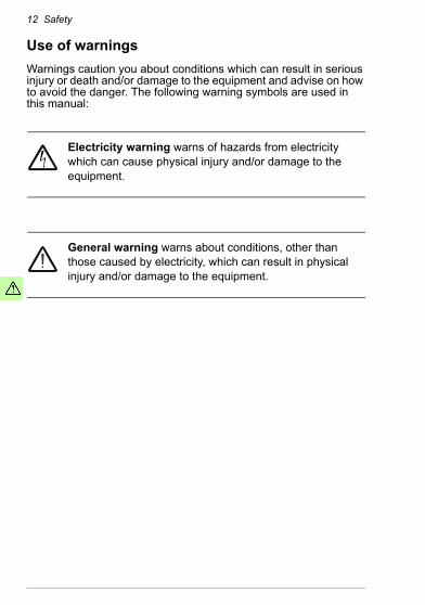
Use of warningsWarnings caution you about conditions which can result in serious injury or death and/or damage to the equipment and advise on how to avoid the danger. The following warning symbols are used in this manual:
Electricity warning warns of hazards from electricity which can cause physical injury and/or damage to the equipment.
General warning warns about conditions, other than those caused by electricity, which can result in physical injury and/or damage to the equipment.
Safety 13
Safety in installationThese warnings are intended for all who install an optional module into a drive, converter or inverter.
WARNING! Ignoring the following instructions can cause physical injury or death, or damage to the equipment.
• Only qualified electricians are allowed to install and maintain the drive, converter or inverter!
• Disconnect the drive, converter or inverter into which the optional module will be installed from all possible power sources. After disconnecting, always wait for 5 minutes to let the intermediate circuit capacitors discharge before you proceed.
• Always ensure by measuring with a multimeter (impedance at least 1 Mohm) that:• there is no voltage between the input power terminals of
the drive, converter or inverter and the ground• there is no voltage between the output power terminals of
the drive, converter or inverter and the ground.• Do not work on the control cables when power is applied to the
external control circuits of the drive, converter or inverter. Externally supplied control circuits may carry dangerous voltage.

14 Safety
About the manual 15
2About the manual
What this chapter containsThis chapter introduces this manual.
ApplicabilityThis manual applies to the FCAN-01 CANopen adapter module (+K457), SW version 1.046 or later.
CompatibilityThe FCAN-01 CANopen adapter module is compatible with the following drives:• ACS355• ACSM1• ACS850• ACS880.
Target audienceThe reader is expected to have basic knowledge of fieldbus interface, electrical fundamentals, electrical wiring practices and how to operate the drive.

16 About the manual
Purpose of the manualThe manual provides information on installing, commissioning and using an FCAN-01 CANopen adapter module.
Related manualsThe related manuals are listed below.
Code (English)Drive user’s manualsACS355 drives (0.37…22 kW, 0.5…30 hp) user’s manual
3AUA0000066143
Drive hardware manuals and guidesACSM1-204 regen supply modules (5.3 to 61 kW) hardware manual
3AUA0000053713
ACSM1-04 drive modules (0.75 to 45 kW) hardware manual
3AFE68797543
ACSM1-04 drive modules (55 to 110 kW) hardware manual
3AFE68912130
ACSM1-04Lx liquid-cooled drive modules (55 to 160 kW) hardware manual
3AUA0000022083
ACS850-04 (0.37…45 kW) hardware manual
3AUA0000045496
ACS850-04 (55…160 kW, 75…200 hp) hardware manual
3AUA0000045487
ACS850-04 (200…500 kW, 250…600 hp) hardware manual
3AUA0000026234
ACS880-01 (0.55 to 250 kW, 0.75 to 350 hp) hardware manual
3AUA0000078093
About the manual 17
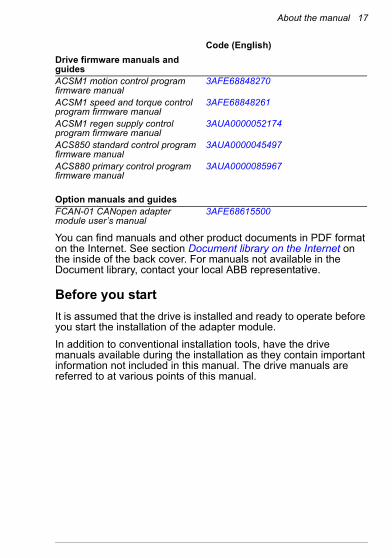
You can find manuals and other product documents in PDF format on the Internet. See section Document library on the Internet on the inside of the back cover. For manuals not available in the Document library, contact your local ABB representative.
Before you startIt is assumed that the drive is installed and ready to operate before you start the installation of the adapter module.In addition to conventional installation tools, have the drive manuals available during the installation as they contain important information not included in this manual. The drive manuals are referred to at various points of this manual.
Drive firmware manuals and guidesACSM1 motion control program firmware manual
3AFE68848270
ACSM1 speed and torque control program firmware manual
3AFE68848261
ACSM1 regen supply control program firmware manual
3AUA0000052174
ACS850 standard control program firmware manual
3AUA0000045497
ACS880 primary control program firmware manual
3AUA0000085967
Option manuals and guidesFCAN-01 CANopen adapter module user’s manual
3AFE68615500
Code (English)
18 About the manual
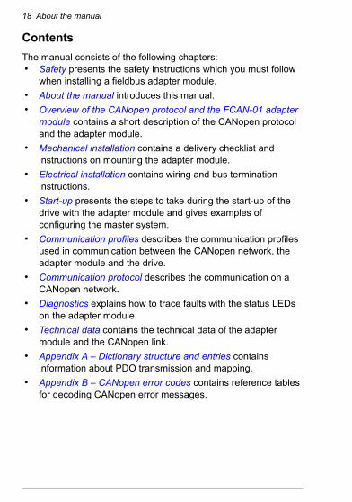
ContentsThe manual consists of the following chapters:• Safety presents the safety instructions which you must follow
when installing a fieldbus adapter module.• About the manual introduces this manual.• Overview of the CANopen protocol and the FCAN-01 adapter
module contains a short description of the CANopen protocol and the adapter module.
• Mechanical installation contains a delivery checklist and instructions on mounting the adapter module.
• Electrical installation contains wiring and bus termination instructions.
• Start-up presents the steps to take during the start-up of the drive with the adapter module and gives examples of configuring the master system.
• Communication profiles describes the communication profiles used in communication between the CANopen network, the adapter module and the drive.
• Communication protocol describes the communication on a CANopen network.
• Diagnostics explains how to trace faults with the status LEDs on the adapter module.
• Technical data contains the technical data of the adapter module and the CANopen link.
• Appendix A – Dictionary structure and entries contains information about PDO transmission and mapping.
• Appendix B – CANopen error codes contains reference tables for decoding CANopen error messages.
About the manual 19
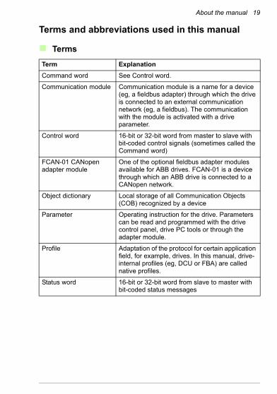
Terms and abbreviations used in this manual
Terms
Term ExplanationCommand word See Control word.
Communication module Communication module is a name for a device (eg, a fieldbus adapter) through which the drive is connected to an external communication network (eg, a fieldbus). The communication with the module is activated with a drive parameter.
Control word 16-bit or 32-bit word from master to slave with bit-coded control signals (sometimes called the Command word)
FCAN-01 CANopen adapter module
One of the optional fieldbus adapter modules available for ABB drives. FCAN-01 is a device through which an ABB drive is connected to a CANopen network.
Object dictionary Local storage of all Communication Objects (COB) recognized by a device
Parameter Operating instruction for the drive. Parameters can be read and programmed with the drive control panel, drive PC tools or through the adapter module.
Profile Adaptation of the protocol for certain application field, for example, drives. In this manual, drive-internal profiles (eg, DCU or FBA) are called native profiles.
Status word 16-bit or 32-bit word from slave to master with bit-coded status messages

20 About the manual
CANopen abbreviations
Abbreviation ExplanationCAN Controller Area Network
CiA CAN in Automation, International User’s and Manufacturer’s Group
CMS CAN Message Specification; one of the service elements of the CAN Application Layer in the CAN Reference Model
COB Grouping of pre-defined data objects accessible via the network.
DBT Distributor; one of the service elements of the CAN Application Layer in the CAN Reference Model. It is the responsibility of the Distributor to distribute COB IDs to the COBs that are used by a CMS.
EDS Electronic Data Sheet; a node-specific ASCII-format file required when configuring the CAN network. The EDS file contains general information on the node and its dictionary objects (parameters). EDS files for ABB Drives are available at the Document library (www.abb.com/drives).
LMT Layer Management; one of the service elements of the CAN Application Layer in the CAN Reference Model. It serves to configure parameters for each layer in the CAN Reference Model.
LSB Least significant bit/byte
MSB Most significant bit/byte
NMT Network Management; one of the service elements of the CAN Application Layer in the CAN Reference Model. It performs initialization, configuration and error handling on a CAN network.
OSI Open Systems Interconnection
PDO Process Data Object; a type of COB. Used for transmitting time critical data, such as control commands, references and actual values.
About the manual 21
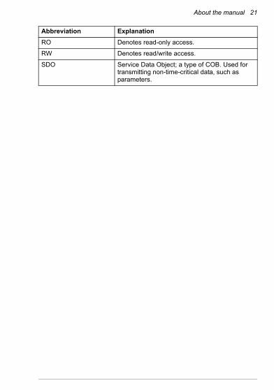
RO Denotes read-only access.
RW Denotes read/write access.
SDO Service Data Object; a type of COB. Used for transmitting non-time-critical data, such as parameters.
Abbreviation Explanation

22 About the manual
Overview of the CANopen protocol and the FCAN-01 adapter module 23
3Overview of the CANopen protocol and the FCAN-01 adapter module
What this chapter containsThis chapter contains a short description of the CANopen protocol and the FCAN-01 CANopen adapter module.
CANopen protocolCANopen is a higher layer protocol based on the CAN (Control Area Network) serial bus system and the CAL (CAN Application Layer). CANopen assumes that the hardware of the connected device has a CAN transceiver and a CAN controller as specified in ISO 11898.The CANopen Communication Profile, CiA 301, includes both cyclic and event driven communication, which makes it possible to reduce the bus load to minimum while still maintaining extremely short reaction times. High communication performance can be achieved at relatively low baud rates, thus reducing EMC problems and cable costs.CANopen device profiles define both direct access to drive parameter and time critical process data communication. The adapter module fulfills CiA (CAN in Automation) specification CiA 402 (CANopen device profile for drives and motion control).
24 Overview of the CANopen protocol and the FCAN-01 adapter module
The physical medium of CANopen is a differentially driven two wire bus line with common return according to ISO 11898. The maximum length of the bus is limited by the communication speed.The maximum theoretical number of nodes is 127. However, in practice, the maximum number depends on the capabilities of the used CAN transceivers.Further information is available from the CAN in Automation International Users and Manufacturers Group (www.can-cia.org).
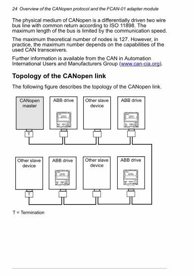
Topology of the CANopen linkThe following figure describes the topology of the CANopen link.
CANopen master
ABB drive
Other slave device
T = Termination
T
ABB drive
ABB drive Other slave device
Other slave device
T
ABB drive
Overview of the CANopen protocol and the FCAN-01 adapter module 25
FCAN-01 CANopen adapter moduleThe FCAN-01 CANopen adapter module is an optional device for ABB drives. It enables the connection of the drive to a CANopen network. The drive is considered as a slave (server) on the CANopen network.Through the adapter module you can:• give control commands to the drive
(for example, Start, Stop, Run enable)• feed a motor speed, torque or position reference to the drive• give a process actual value or a process reference to the PID
controller of the drive• read status information and actual values from the drive• change drive parameter values• reset a drive fault.
The CANopen commands and services supported by the adapter module are discussed in chapter Communication protocol. Refer to the drive manuals as to which commands are supported by the drive.The adapter module is mounted into an option slot on the motor control board of the drive. See the drive manuals for module placement options.

26 Overview of the CANopen protocol and the FCAN-01 adapter module
Layout of the adapter moduleThe following figure describes the layout of the adapter module.
Diagnostic LEDs (see chapter Diagnostics)
Bus connector X1(see chapter Electrical installation)Mounting screw
Mechanical installation 27
4Mechanical installation
What this chapter containsThis chapter contains a delivery checklist and instructions on mounting the adapter module.
WARNING! Follow the safety instructions given in this manual and the drive documentation.
Delivery checkThe option package for the adapter module contains:• CANopen adapter module, type FCAN-01• this manual.

28 Mechanical installation
Mounting the adapter moduleThe adapter module is inserted into its specific position in the drive. The module is held in place with plastic pins and one screw. The screw also provides the electrical connection between the module and drive frame for cable shield termination.When the module is installed, the signal and power connection to the drive is made through a 20-pin connector. (All drives do not use all the available signals so the connector on the drive may have fewer pins.)Mounting procedure:1. Insert the module carefully into its position on the drive.
2. Fasten the screw.
Note: It is essential to install the screw properly to fulfill the EMC requirements and to ensure the proper operation of the module.For more information on mounting the adapter module, see the drive manuals.
Electrical installation 29
5Electrical installation
What this chapter containsThis chapter contains:• general cabling instructions• bus termination instructions• instructions on connecting the adapter module to the CANopen
network.
WARNING! Before installation, switch off the drive power supply. Wait five minutes to ensure that the capacitor bank of the drive is discharged. Switch off all dangerous
voltages connected from external control circuits to the inputs and outputs of the drive.
General cabling instructions• Arrange the bus cables as far away from the motor cables as
possible.• Avoid parallel runs.• Use bushings at cable entries.
30 Electrical installation
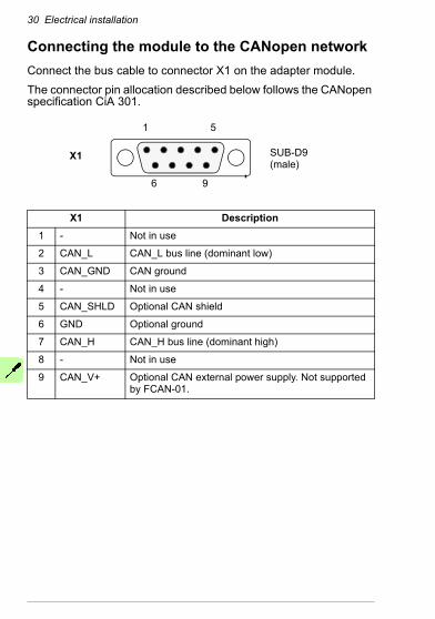
Connecting the module to the CANopen networkConnect the bus cable to connector X1 on the adapter module.The connector pin allocation described below follows the CANopen specification CiA 301.
X1 Description1 - Not in use
2 CAN_L CAN_L bus line (dominant low)
3 CAN_GND CAN ground
4 - Not in use
5 CAN_SHLD Optional CAN shield
6 GND Optional ground
7 CAN_H CAN_H bus line (dominant high)
8 - Not in use
9 CAN_V+ Optional CAN external power supply. Not supported by FCAN-01.
5
96
1
X1 SUB-D9 (male)
Electrical installation 31
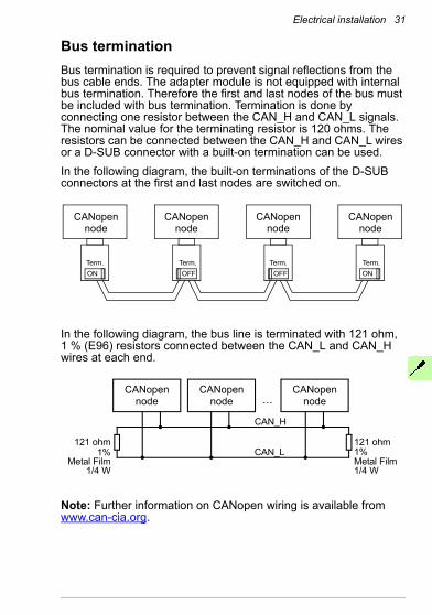
Bus terminationBus termination is required to prevent signal reflections from the bus cable ends. The adapter module is not equipped with internal bus termination. Therefore the first and last nodes of the bus must be included with bus termination. Termination is done by connecting one resistor between the CAN_H and CAN_L signals. The nominal value for the terminating resistor is 120 ohms. The resistors can be connected between the CAN_H and CAN_L wires or a D-SUB connector with a built-on termination can be used.In the following diagram, the built-on terminations of the D-SUB connectors at the first and last nodes are switched on.
In the following diagram, the bus line is terminated with 121 ohm, 1 % (E96) resistors connected between the CAN_L and CAN_H wires at each end.
Note: Further information on CANopen wiring is available from www.can-cia.org.
CANopennode
ON
CANopennode
OFF
CANopennode
ON
CANopennode
OFFTerm. Term. Term. Term.
121 ohm
CAN_H
CAN_L121 ohm
1%Metal Film1/4 W
1%Metal Film
1/4 W
CANopennode
CANopennode
CANopennode…
32 Electrical installation
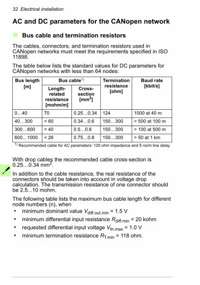
AC and DC parameters for the CANopen network
Bus cable and termination resistorsThe cables, connectors, and termination resistors used in CANopen networks must meet the requirements specified in ISO 11898.The table below lists the standard values for DC parameters for CANopen networks with less than 64 nodes:
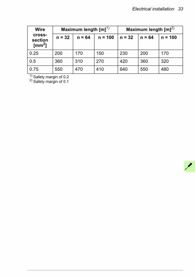
With drop cables the recommended cable cross-section is 0.25…0.34 mm2.In addition to the cable resistance, the real resistance of the connectors should be taken into account in voltage drop calculation. The transmission resistance of one connector should be 2.5...10 mohm. The following table lists the maximum bus cable length for different node numbers (n), when• minimum dominant value Vdiff.out.min = 1.5 V• minimum differential input resistance Rdiff.min = 20 kohm• requested differential input voltage Vth.max = 1.0 V• minimum termination resistance RT.min = 118 ohm.
Bus length[m]
Bus cable1) Termination resistance
[ohm]
Baud rate [kbit/s]Length-
related resistance [mohm/m]
Cross-section [mm2]
0…40 70 0.25…0.34 124 1000 at 40 m
40…300 < 60 0.34…0.6 150…300 > 500 at 100 m
300…600 < 40 0.5…0.6 150…300 > 100 at 500 m
600…1000 < 26 0.75…0.8 150…300 > 50 at 1 km1) Recommended cable for AC parameters: 120 ohm impedance and 5 ns/m line delay
Electrical installation 33
Wire cross-section [mm2]
Maximum length [m]1) Maximum length [m]2)
n = 32 n = 64 n = 100 n = 32 n = 64 n = 100
0.25 200 170 150 230 200 170
0.5 360 310 270 420 360 320
0.75 550 470 410 640 550 4801) Safety margin of 0.22) Safety margin of 0.1

34 Electrical installation
Start-up 35
6Start-up
What this chapter containsThis chapter contains:• information on configuring the drive for operation with the
adapter module• drive-specific instructions on starting up the drive with the
adapter module• examples of configuring the master station for communication
with the adapter module.
WARNING! Follow the safety instructions given in this manual and the drive documentation.
Drive configurationThe following information applies to all drive types compatible with the adapter module, unless otherwise stated.
36 Start-up
CANopen connection configurationAfter the adapter module has been mechanically and electrically installed according to the instructions in chapters Mechanical installation and Electrical installation, the drive must be prepared for communication with the module.The detailed procedure of activating the module for CANopen communication with the drive depends on the drive type. Normally, a parameter must be adjusted to activate the communication. See the drive-specific start-up sections on pages 58, 64, 69 and 75.Once communication between the drive and the adapter module has been established, several configuration parameters are copied to the drive. These parameters are shown in the tables below and must be checked first and adjusted where necessary.Note: Not all drives display descriptive names for the configuration parameters. To help you identify the parameters in different drives, the names displayed by each drive are given in grey boxes in the tables.An example on how to configure PDOs via the CAN bus is given in section PDO configuration via the CAN bus.Note: The new settings take effect only when the adapter module is powered up the next time or when the fieldbus adapter refresh parameter is activated.
Data transfer rates supported
The FCAN-01 CANopen adapter module supports the following CANopen communication speeds: 50 kbit/s, 100 kbit/s, 125 kbit/s, 250 kbit/s, 500 kbit/s, 1 Mbit/s.Note: The CANopen standard CiA 301 does not list 100 kbit/s as a recommended bit rate, and therefore it should not be used in new installations.

Start-up 37
FCAN-01 configuration parameters – group A (group 1)
Note: The actual parameter group number depends on the drive type. Group A (group 1) corresponds to:• parameter group 51 in ACS355, ACSM1 and ACS850• parameter group 51 in ACS880 if the adapter is installed as
fieldbus adapter A or group 54 if the adapter is installed as fieldbus adapter B.
No. Name/Value Description Default setting
01 FBA TYPE Read-only. Shows the fieldbus adapter type as detected by the drive. Value cannot be adjusted by the user.If the value is 0 = None, the communication between the drive and the module has not been established.
1 = CAN-open
02 NODE ID Selects the node address of the module.Each device on the CANopen network must have a unique node identifier. Used to define a node identifier for the drive it is connected to.
3
ACS355:FB PAR 2ACSM1: FBA PAR2ACS850:FBA par2ACS880:Node ID
1…127 Node address
38 Start-up
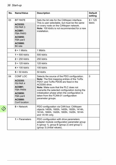
03 BIT RATE Sets the bit rate for the CANopen interface. This is user selectable, but must be the same on every node on the CANopen network.Note: 100 kbit/s is not recommended for a new installation.
3 = 125kbit/sACS355:
FB PAR 3ACSM1:FBA PAR3ACS850:FBA par3ACS880:Bit rate
0 = 1 Mbit/s 1 Mbit/s
1 = 500 kbit/s 500 kbit/s
2 = 250 kbit/s 250 kbit/s
3 = 125 kbit/s 125 kbit/s
4 = 100 kbit/s 100 kbit/s
5 = 50 kbit/s 50 kbit/s
04 CONF LOC Selects the source of the PDO configuration.Note: The first mapping entries of the Tx/Rx PDO1 and Tx/Rx PDO6 are fixed in the ACS355 drive.Note: Make sure that the PLC does not overwrite the selected configuration during the initialization phase when the configuration is taken from the FCAN-01 configuration parameter groups.
0
ACS355:FB PAR 4ACSM1: FBA PAR4ACS850:FBA par4ACS880:Conf location
0 = Network PDO configuration via CAN bus: CANopen objects 1400h, 1600h, 1405h, 1605h, 1414h, 1614h, 1800h, 1A00h, 1805h, 1A05h, 1814h and 1A14h only.
1 = Parameters PDO configuration with drive parameters: adapter module configuration parameter group A (group 1), group B (group 2) and group C (group 3) (initial values).
No. Name/Value Description Default setting
Start-up 39
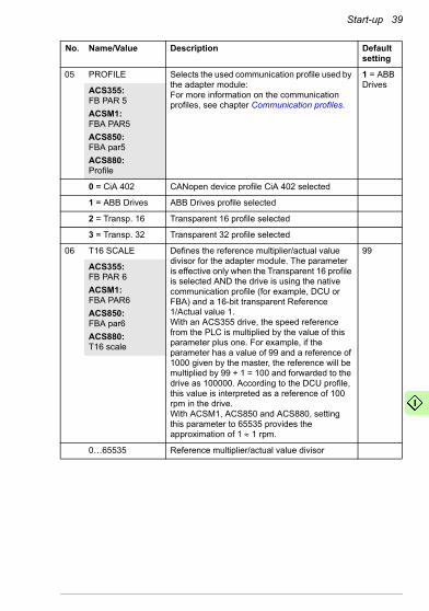
05 PROFILE Selects the used communication profile used by the adapter module:For more information on the communication profiles, see chapter Communication profiles.
1 = ABB DrivesACS355:
FB PAR 5ACSM1: FBA PAR5ACS850:FBA par5ACS880:Profile
0 = CiA 402 CANopen device profile CiA 402 selected
1 = ABB Drives ABB Drives profile selected
2 = Transp. 16 Transparent 16 profile selected
3 = Transp. 32 Transparent 32 profile selected
06 T16 SCALE Defines the reference multiplier/actual value divisor for the adapter module. The parameter is effective only when the Transparent 16 profile is selected AND the drive is using the native communication profile (for example, DCU or FBA) and a 16-bit transparent Reference 1/Actual value 1.With an ACS355 drive, the speed reference from the PLC is multiplied by the value of this parameter plus one. For example, if the parameter has a value of 99 and a reference of 1000 given by the master, the reference will be multiplied by 99 + 1 = 100 and forwarded to the drive as 100000. According to the DCU profile, this value is interpreted as a reference of 100 rpm in the drive.With ACSM1, ACS850 and ACS880, setting this parameter to 65535 provides the approximation of 1 ≈ 1 rpm.
99
ACS355:FB PAR 6ACSM1: FBA PAR6ACS850:FBA par6ACS880:T16 scale
0…65535 Reference multiplier/actual value divisor
No. Name/Value Description Default setting

40 Start-up
07 RPDO1-COB-ID Defines the COB-ID for Rx PDO1.Note: It is recommended to use the default COB-ID.
1
ACS355:FB PAR 7ACSM1: FBA PAR7ACS850:FBA par7ACS880:RPDO1-COB-ID
0 = Disable Rx PDO1 is not valid (disabled). COB-ID is 80000200h + Node-ID.
1 = Default Rx PDO1 is valid and configured to use the default COB-ID (200h + Node-ID).
385…1407 (dec) = 181h … 57Fh
Rx PDO1 is valid and configured to use a custom COB-ID defined with this parameter. COB-ID must be within the allowed PDO COB-ID range (181h - 57Fh).
08 RPDO1-TR TYPE Defines the Rx PDO1 transmission type. See chapter Appendix A – Dictionary structure and entries.
255
ACS355:FB PAR 8ACSM1: FBA PAR8ACS850:FBA par8ACS880:RPDO1-TR type
0…255 (dec) Rx PDO1 transmission type. See section Description of transmission type on page 158.
No. Name/Value Description Default setting
Start-up 41
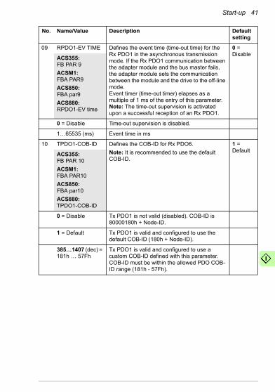
09 RPDO1-EV TIME Defines the event time (time-out time) for the Rx PDO1 in the asynchronous transmission mode. If the Rx PDO1 communication between the adapter module and the bus master fails, the adapter module sets the communication between the module and the drive to the off-line mode.Event timer (time-out timer) elapses as a multiple of 1 ms of the entry of this parameter.Note: The time-out supervision is activated upon a successful reception of an Rx PDO1.
0 = DisableACS355:
FB PAR 9ACSM1: FBA PAR9ACS850:FBA par9ACS880:RPDO1-EV time
0 = Disable Time-out supervision is disabled.
1…65535 (ms) Event time in ms
10 TPDO1-COB-ID Defines the COB-ID for Rx PDO6.Note: It is recommended to use the default COB-ID.
1 = DefaultACS355:
FB PAR 10ACSM1: FBA PAR10ACS850:FBA par10ACS880:TPDO1-COB-ID
0 = Disable Tx PDO1 is not valid (disabled). COB-ID is 80000180h + Node-ID.
1 = Default Tx PDO1 is valid and configured to use the default COB-ID (180h + Node-ID).
385…1407 (dec) = 181h … 57Fh
Tx PDO1 is valid and configured to use a custom COB-ID defined with this parameter. COB-ID must be within the allowed PDO COB-ID range (181h - 57Fh).
No. Name/Value Description Default setting

42 Start-up
11 TPDO1-TR TYPE Defines the PDO1 transmission type. See chapter Appendix A – Dictionary structure and entries.
255
ACS355:FB PAR 11ACSM1: FBA PAR11ACS850:FBA par11ACS880:TPDO1-TR type
0…255 (dec) PDO1 transmission type. See section Description of transmission type on page 158.
12 TPDO1-EV TIME Defines the event time for the Tx PDO1 asynchronous transmission mode.Event timer elapses as a multiple of 1 ms of the entry of this parameter.
0 = DisableACS355:
FB PAR 12ACSM1: FBA PAR12ACS850:FBA par12ACS880:TPDO1-EV time
0 = Disable Event timer is disabled.
1…65535 (ms) Event time in ms.
13 RPDO6-COB-ID Defines the COB-ID for Rx PDO6.Note: It is recommended to use the default COB-ID.
0 = DisableACS355:
FB PAR 13ACSM1: FBA PAR13ACS850:FBA par13ACS880:RPDO6-COB-ID
0 = Disable Rx PDO6 is not valid (disabled). COB-ID is 80000300h + Node-ID.
1 = Default Rx PDO6 is valid and configured to use the default COB-ID (300h + Node-ID).
385…1407 (dec) = 181h … 57Fh
Rx PDO1 is valid and configured to use a custom COB-ID defined with this parameter. COB-ID must be within the allowed PDO COB-ID range (181h - 57Fh).
No. Name/Value Description Default setting

Start-up 43
14 RPDO6-TR TYPE Defines the Rx PDO6 transmission type. See chapter Appendix A – Dictionary structure and entries.
255
ACS355:FB PAR 14ACSM1: FBA PAR14ACS850:FBA par14ACS880:RPDO6-TR type
0…255 (dec) Rx PDO6 transmission type. See section Description of transmission type on page 158.
15 RPDO6-EV TIME Defines the event time (time-out time) for the Rx PDO6 in the asynchronous transmission mode. If the Rx PDO6 communication between the adapter module and the bus master fails, the adapter module sets the communication between the module and the drive to the off-line mode.Event timer (time-out timer) elapses as a multiple of 1 ms of the entry of this parameter.Note: The time-out supervision is activated upon a successful reception of an Rx PDO6.
0 = DisableACS355:
FB PAR 15ACSM1: FBA PAR15ACS850:FBA par15ACS880:RPDO6-EV time
0 = Disable Time-out supervision is disabled.
1…65535 (ms) Event time in ms.
16 TPDO6-COB-ID Defines the COB-ID for Tx PDO6.Note: It is recommended to use the default COB-ID.
0 = DisableACS355:
FB PAR 16ACSM1: FBA PAR16ACS850:FBA par16ACS880:TPDO6-COB-ID
0 = Disable Tx PDO6 is not valid (disabled). COB-ID is 80000280h + Node-ID.
1 = Default Tx PDO6 is valid and configured to use the default COB-ID (280h + Node-ID).
385…1407 (dec) = 181h … 57Fh
Tx PDO6 is valid and configured to use a custom COB-ID defined with this parameter. COB-ID must be within the allowed PDO COB-ID range (181h - 57Fh).
No. Name/Value Description Default setting

44 Start-up
17 TPDO6-TR TYPE Defines the Tx PDO6 transmission type. See chapter Appendix A – Dictionary structure and entries.
255
ACS355:FB PAR 17ACSM1: FBA PAR17ACS850:FBA par17ACS880:TPDO6-TR type
0…255 (dec) Tx PDO6 transmission type. See section Description of transmission type on page 158.
18 TPDO6-EV TIME Defines the event time for the Tx PDO6 asynchronous transmission mode.Event timer elapses as a multiple of 1 ms of the entry of this parameter.
0 = DisableACS355:
FB PAR 18ACSM1: FBA PAR18ACS850:FBA par18ACS880:TPDO6-EV time
0 = Disable Event timer is disabled.
1…65535 (ms) Event time in ms.
19 RPDO21-COB-ID Defines the COB-ID for Rx PDO21.Note: It is recommended to use the default COB-ID.
0 = DisableACS355:
FB PAR 19ACSM1: FBA PAR19ACS850:FBA par19ACS880:RPDO21-COB-ID
0 = Disable Rx PDO21 is not valid (disabled). COB-ID is 80000400h + Node-ID.
1 = Default Rx PDO21 is valid and configured to use the default COB-ID (400h + Node-ID).
385…1407 (dec) = 181h … 57Fh
Rx PDO21 is valid and configured to use a custom COB-ID defined with this parameter. COB-ID must be within the allowed PDO COB-ID range (181h - 57Fh).
No. Name/Value Description Default setting

Start-up 45
20 RPDO21-TR TYPE
Defines the Rx PDO21 transmission type. See chapter Appendix A – Dictionary structure and entries.
255
ACS355:FB PAR 20ACSM1: FBA PAR20ACS850:FBA par20ACS880:RPDO21-TR type
0…255 (dec) Rx PDO21 transmission type. See section Description of transmission type on page 158.
21 RPDO21-EV TIME Defines the event time (time-out time) for the Rx PDO21 in the asynchronous transmission mode. If the Rx PDO21 communication between the adapter module and the bus master fails, the adapter module sets the communication between the module and the drive to the off-line mode.Event timer (time-out timer) elapses as a multiple of 1 ms of the entry of this parameter.Note: The time-out supervision is activated upon a successful reception of an Rx PDO21.
0 = DisableACS355:
FB PAR 21ACSM1: FBA PAR21ACS850:FBA par21ACS880:RPDO21-EV time
0 = Disable Time-out supervision is disabled.
1…65535 (ms) Event time in ms.
No. Name/Value Description Default setting
46 Start-up
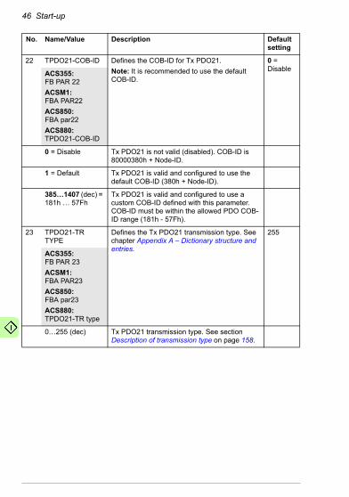
22 TPDO21-COB-ID Defines the COB-ID for Tx PDO21.Note: It is recommended to use the default COB-ID.
0 = DisableACS355:
FB PAR 22ACSM1: FBA PAR22ACS850:FBA par22ACS880:TPDO21-COB-ID
0 = Disable Tx PDO21 is not valid (disabled). COB-ID is 80000380h + Node-ID.
1 = Default Tx PDO21 is valid and configured to use the default COB-ID (380h + Node-ID).
385…1407 (dec) = 181h … 57Fh
Tx PDO21 is valid and configured to use a custom COB-ID defined with this parameter. COB-ID must be within the allowed PDO COB-ID range (181h - 57Fh).
23 TPDO21-TR TYPE
Defines the Tx PDO21 transmission type. See chapter Appendix A – Dictionary structure and entries.
255
ACS355:FB PAR 23ACSM1: FBA PAR23ACS850:FBA par23ACS880:TPDO21-TR type
0…255 (dec) Tx PDO21 transmission type. See section Description of transmission type on page 158.
No. Name/Value Description Default setting
Start-up 47
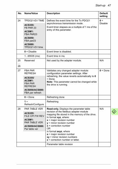
24 TPDO21-EV TIME Defines the event time for the Tx PDO21 asynchronous transmission mode.Event timer elapses as a multiple of 1 ms of the entry of this parameter.
0 = DisableACS355:
FB PAR 23ACSM1: FBA PAR23ACS850:FBA par23ACS880:TPDO21-EV time
0 = Disable Event timer is disabled.
1...65535 (ms) Event time in ms.
25…26
Reserved Not used by the adapter module. N/A
27 FBA PAR REFRESH
Validates any changed adapter module configuration parameter settings. After refreshing, the value reverts automatically to 0 = Done.Note: This parameter cannot be changed while the drive is running.
0 = Done
ACS355/ACSM1: FBA PAR REFRESHACS850/ACS880:FBA par refresh
0 = Done Refreshing done
1 = Refresh/Configure
Refreshing
28 PAR TABLE VER Read-only. Displays the parameter table revision of the fieldbus adapter module mapping file stored in the memory of the drive.In format xyz, where:x = major revision numbery = minor revision numberx = correction numberORin format axyz, wherea = major revision numberxy = minor revision numbersz = correction number or letter.
N/A
ACS355: FILE CPI FW REVACSM1: PAR TABLE VERACS850/ACS880:Par table ver
Parameter table revision
No. Name/Value Description Default setting

48 Start-up
29 DRIVE TYPE CODE
Read-only. Displays the drive type code of the fieldbus adapter module mapping file stored in the memory of the drive.
N/A
ACS355: FILE CONFIG IDACSM1: DRIVE TYPE CODACS850/ACS880:Drive type code
Drive type code of the fieldbus adapter module mapping file
30 MAPPING FILE VER
Read-only. Displays the fieldbus adapter module mapping file revision stored in the memory of the drive in decimal format.
N/A
ACS355: FILE CONFIG REVACSM1: MAPPING FILE VERACS850/ACS880:Mapping file ver
Mapping file revision
No. Name/Value Description Default setting
Start-up 49
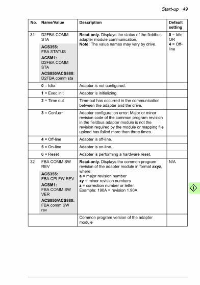
31 D2FBA COMM STA
Read-only. Displays the status of the fieldbus adapter module communication.Note: The value names may vary by drive.
0 = IdleOR4 = Off-lineACS355:
FBA STATUSACSM1: D2FBA COMM STAACS850/ACS880:D2FBA comm sta
0 = Idle Adapter is not configured.
1 = Exec.init Adapter is initializing.
2 = Time out Time-out has occurred in the communication between the adapter and the drive.
3 = Conf.err Adapter configuration error: Major or minor revision code of the common program revision in the fieldbus adapter module is not the revision required by the module or mapping file upload has failed more than three times.
4 = Off-line Adapter is off-line.
5 = On-line Adapter is on-line.
6 = Reset Adapter is performing a hardware reset.
32 FBA COMM SW REV
Read-only. Displays the common program revision of the adapter module in format axyz, where:a = major revision numberxy = minor revision numbersz = correction number or letter.Example: 190A = revision 1.90A
N/A
ACS355: FBA CPI FW REVACSM1: FBA COMM SW VERACS850/ACS880:FBA comm SW rev
Common program version of the adapter module
No. Name/Value Description Default setting
50 Start-up
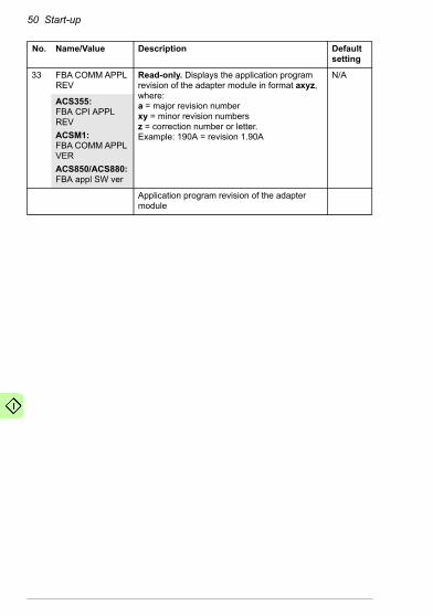
33 FBA COMM APPL REV
Read-only. Displays the application program revision of the adapter module in format axyz, where:a = major revision numberxy = minor revision numbersz = correction number or letter.Example: 190A = revision 1.90A
N/A
ACS355: FBA CPI APPL REVACSM1: FBA COMM APPL VERACS850/ACS880:FBA appl SW ver
Application program revision of the adapter module
No. Name/Value Description Default setting

Start-up 51
FCAN-01 configuration parameters – group B (group 2)
Note: The actual parameter group number depends on the drive type. Group B (group 2) corresponds to:• parameter group 55 in ACS355• group 53 in ACSM1 and ACS850• parameter group 53 in ACS880 if the adapter is installed as
fieldbus adapter A or group 56 if the adapter is installed as fieldbus adapter B.
No.1) Name2)/Value Description Default
01 For ACS355:Rx PDO1 word 2For other drives:Rx PDO1 word 1
Selects data word 1 received by the drive over the CANopen network. From the drive's perspective this corresponds to Rx PDO communication in CANopen.
0 = Not used
ACS355:FBA DATA OUT 1ACSM1: FBA DATA OUT1ACS850/ACS880:FBA data out1
Content is defined by a decimal number in the range of 0 to 9999 as follows:
See also Additional information on the virtual address area allocation on page 57.
Note: The FCAN-01 configuration parameters are 16-bit parameters. If the mapped parameter is a 32-bit parameter, it automatically reserves two consecutive parameters. For example, mapping of a 32-bit parameter to parameter no. 1 also reserves parameter no. 2.Note: In ACS355 drives, Rx PDO1 word 1 and Rx PDO6 word 1 are fixed and always mapped to object 6040h Control word. The first configuration parameters have effect on the 2nd words of these PDOs in ACS355 drives.
CANopen master
ABB drive
Control word (CW)References
FBA DATA OUT(Rx PDO)
0 Not used
1…99 Virtual address area of drive control
101…9999
Parameter area of the drive

52 Start-up
0 = None Not used
1 = CW 16bit Control word (16 bits)
2 = Ref1 16bit Reference REF1 (16 bits)
3 = Ref2 16bit Reference REF2 (16 bits)
11 = CW 32bit Control word (32 bits)
12 = Ref1 32bit Reference REF1 (32 bits)
13 = Ref2 32bit Reference REF2 (32 bits)
101…9999 Parameter number with format xxyy, where:• xx is the parameter group number (1 to 99)• yy is the parameter number index within that
group (01 to 99).Note: In ACS880, choose Other to display a list of mappable drive parameters.
02 For ACS355:Rx PDO1 word 3For other drives:Rx PDO1 word 2
See parameter 01 above. 0
03 For ACS355:Rx PDO1 word 4For other drives:Rx PDO1 word 3
See parameter 01 above. 0
04 For ACS355:Rx PDO6 word 2For other drives:Rx PDO1 word 4
See parameter 01 above. 0
05 For ACS355:Rx PDO6 word 3For other drives:Rx PDO6 word 1
See parameter 01 above. 0
06 For ACS355:Rx PDO6 word 4For other drives:Rx PDO6 word 2
See parameter 01 above. 0
07 For ACS355:Rx PDO21 word 1For other drives:Rx PDO6 word 3
See parameter 01 above. 0
08 For ACS355:Rx PDO21 word 2For other drives:Rx PDO6 word 4
See parameter 01 above. 0
No.1) Name2)/Value Description Default
Start-up 53
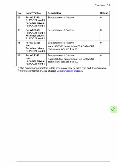
09 For ACS355:Rx PDO21 word 3For other drives:Rx PDO21 word 1
See parameter 01 above. 0
10 For ACS355:Rx PDO21 word 4For other drives:Rx PDO21 word 2
See parameter 01 above. 0
11 For ACS355:N/AFor other drives:Rx PDO21 word 3
See parameter 01 above.Note: ACS355 has only ten FBA DATA OUT parameters, indexes 1 to 10.
0
12 For ACS355:N/AFor other drives:Rx PDO21 word 4
See parameter 01 above.Note: ACS355 has only ten FBA DATA OUT parameters, indexes 1 to 10.
0
1) The number of parameters in this group may vary by drive type and drive firmware.2) For more information, see chapter Communication protocol.
No.1) Name2)/Value Description Default
54 Start-up
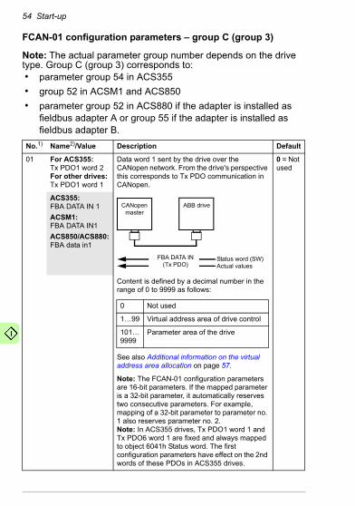
FCAN-01 configuration parameters – group C (group 3)
Note: The actual parameter group number depends on the drive type. Group C (group 3) corresponds to:• parameter group 54 in ACS355• group 52 in ACSM1 and ACS850• parameter group 52 in ACS880 if the adapter is installed as
fieldbus adapter A or group 55 if the adapter is installed as fieldbus adapter B.
No.1) Name2)/Value Description Default
01 For ACS355:Tx PDO1 word 2For other drives:Tx PDO1 word 1
Data word 1 sent by the drive over the CANopen network. From the drive's perspective this corresponds to Tx PDO communication in CANopen.
0 = Not used
ACS355:FBA DATA IN 1ACSM1: FBA DATA IN1ACS850/ACS880:FBA data in1
Content is defined by a decimal number in the range of 0 to 9999 as follows:
See also Additional information on the virtual address area allocation on page 57.
Note: The FCAN-01 configuration parameters are 16-bit parameters. If the mapped parameter is a 32-bit parameter, it automatically reserves two consecutive parameters. For example, mapping of a 32-bit parameter to parameter no. 1 also reserves parameter no. 2.Note: In ACS355 drives, Tx PDO1 word 1 and Tx PDO6 word 1 are fixed and always mapped to object 6041h Status word. The first configuration parameters have effect on the 2nd words of these PDOs in ACS355 drives.
CANopen master
ABB drive
Status word (SW)Actual values
FBA DATA IN(Tx PDO)
0 Not used
1…99 Virtual address area of drive control
101…9999
Parameter area of the drive
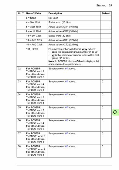
Start-up 55
0 = None Not used
4 = SW 16bit Status word (16 bits)
5 = Act1 16bit Actual value ACT1 (16 bits)
6 = Act2 16bit Actual value ACT2 (16 bits)
14 = SW 32bit Status word (32 bits)
15 = Act1 32bit Actual value ACT1 (32 bits)
16 = Act2 32bit Actual value ACT2 (32 bits)
101…9999 Parameter number with format xxyy, where:• xx is the parameter group number (1 to 99)• yy is the parameter number index within that
group (01 to 99).Note: In ACS880, choose Other to display a list of mappable drive parameters.
02 For ACS355:Tx PDO1 word 3For other drives:Tx PDO1 word 2
See parameter 01 above. 0
03 For ACS355:Tx PDO1 word 4For other drives:Tx PDO1 word 3
See parameter 01 above. 0
04 For ACS355:Tx PDO6 word 2For other drives:Tx PDO1 word 4
See parameter 01 above. 0
05 For ACS355:Tx PDO6 word 3For other drives:Tx PDO6 word 1
See parameter 01 above. 0
06 For ACS355:Tx PDO6 word 4For other drives:Tx PDO6 word 2
See parameter 01 above. 0
07 For ACS355:Tx PDO21 word 1For other drives:Tx PDO6 word 3
See parameter 01 above. 0
08 For ACS355:Tx PDO21 word 2For other drives:Tx PDO6 word 4
See parameter 01 above. 0
No.1) Name2)/Value Description Default

56 Start-up
09 For ACS355:Tx PDO21 word 3For other drives:Tx PDO21 word 1
See parameter 01 above. 0
10 For ACS355:Tx PDO21 word 4For other drives:Tx PDO21 word 2
See parameter 01 above. 0
11 For ACS355:N/AFor other drives:Tx PDO21 word 3
See parameter 01 above.Note: ACS355 has only ten FBA DATA IN parameters, indexes 1 to 10.
0
12 For ACS355:N/AFor other drives:Tx PDO21 word 4
See parameter 01 above.Note: ACS355 has only ten FBA DATA IN parameters, indexes 1 to 10.
0
1) The number of parameters in this group may vary by drive type and drive firmware.2) For more information, see chapter Communication protocol.
No.1) Name2)/Value Description Default
Start-up 57
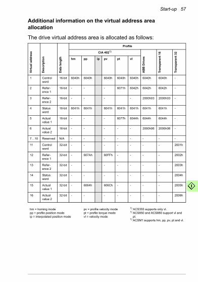
Additional information on the virtual address areaallocation
The drive virtual address area is allocated as follows:Vi
rtua
l add
ress
Des
crip
tion
Dat
a le
ngth
Profile
CiA 4021)
AB
B D
rives
Tran
spar
ent 1
6
Tran
spar
ent 3
2
hm pp ip pv pt vl
1 Controlword
16-bit 6040h 6040h 6040h 6040h 6040h 6040h 6040h -
2 Refer-ence 1
16-bit - - - 6071h 6042h 6042h 6042h -
3 Refer-ence 2
16-bit - - - - 2000h03 2000h03 -
4 Statusword
16-bit 6041h 6041h 6041h 6041h 6041h 6041h 6041h -
5 Actualvalue 1
16-bit - - - 6077h 6044h 6044h 6044h -
6 Actualvalue 2
16-bit - - - - - 2000h06 2000h06 -
7…10 Reserved N/A - - - - - - - -
11 Controlword
32-bit - - - - - - - 2001h
12 Refer-ence 1
32-bit - 607Ah 60FFh - - - - 2002h
13 Refer-ence 2
32-bit - - - - - - - 2003h
14 Statusword
32-bit - - - - - - - 2004h
15 Actualvalue 1
32-bit - 6064h 606Ch - - - - 2005h
16 Actualvalue 2
32-bit - - - - - - - 2006h
hm = homing modepp = profile position modeip = interpolated position mode
pv = profile velocity modept = profile torque modevl = velocity mode
1) ACS355 supports only vl.1) ACS850 and ACS880 support vl and
pt.1) ACSM1 supports hm, pp, pv, pt and vl.

58 Start-up
Control locationsABB drives can receive control information from multiple sources including digital inputs, analog inputs, the drive control panel and a communication module (for example, FCAN-01). ABB drives allow the user to separately determine the source for each type of control information (Start, Stop, Direction, Reference, Fault reset, etc.).To give the fieldbus master station the most complete control over the drive, the communication module must be selected as the source of this information. The drive-specific parameter setting examples below contain the drive control parameters needed in the examples. For a complete parameter list, see the drive documentation.
Starting up ACS355 drives1. Power up the drive.
2. Enable the communication between the adapter module and the drive with parameter 9802 COMM PROT SEL.
3. Set the FCAN configuration parameters in drive parameter group 51.At the minimum, set the required node address in parameter 5102 NODE ID, the required bit rate in 5103 BIT RATE, select the source of the PDO configuration in 5104 CONF LOC and the communication profile in 5105 PROFILE.
4. With parameter 3018 COMM FAULT FUNC, select how the drive reacts to a fieldbus communication break.
5. With parameter 3019 COMM FAULT TIME, define the time between communication break detection and the selected action.
6. If group 51 is selected as the source for the PDO configuration, select the application specific configuration for the PDOs with parameters 5107…5124.

Start-up 59
7. If group 51 is selected as the source for the PDO configuration, define the process data transferred to and from the drive in FCAN-01 parameter groups 54 and 55.Note: If the PDO configuration is written from the PLC, parameters 5107…5124 are not used and the parameter groups 54 and 55 display the process data selected in the PLC.
8. To validate the settings made in parameter groups 51, 54 and 55, set parameter 5127 FBA PAR REFRESH to REFRESH.
9. Set the relevant drive control parameters to control the drive according to the application.Examples of appropriate values are shown in the tables below.
Parameter setting examples – ACS355
CiA 402 vl velocity mode with default PDO mapping
The following example shows how to configure a basic speed control application that uses the CiA 402 profile. The start/stop commands are according to the CiA 402 profile velocity control mode.Rx PDO1 and Tx PDO1 are enabled by default. In ACS355 drives, the first mapping entries of Rx PDO1 and Tx PDO1 are fixed and always mapped to objects 6040h and 6041h.
Note: The Tx PDO1 default transmission type is 255 (asynchronous) and event time is 0. The event time should be changed with CANopen object 1800h05 if the default transmission type is used.
PDO Word 1 Length
Rx PDO1 6040h Control word 16 bits
Tx PDO1 6041h Status word 16 bits
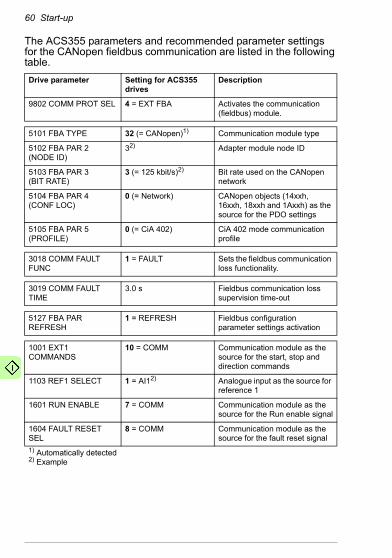
60 Start-up
The ACS355 parameters and recommended parameter settings for the CANopen fieldbus communication are listed in the following table.Drive parameter Setting for ACS355
drivesDescription
9802 COMM PROT SEL 4 = EXT FBA Activates the communication (fieldbus) module.
5101 FBA TYPE 32 (= CANopen)1) Communication module type
5102 FBA PAR 2(NODE ID)
32) Adapter module node ID
5103 FBA PAR 3(BIT RATE)
3 (= 125 kbit/s)2) Bit rate used on the CANopen network
5104 FBA PAR 4(CONF LOC)
0 (= Network) CANopen objects (14xxh, 16xxh, 18xxh and 1Axxh) as the source for the PDO settings
5105 FBA PAR 5(PROFILE)
0 (= CiA 402) CiA 402 mode communication profile
3018 COMM FAULT FUNC
1 = FAULT Sets the fieldbus communication loss functionality.
3019 COMM FAULT TIME
3.0 s Fieldbus communication loss supervision time-out
5127 FBA PAR REFRESH
1 = REFRESH Fieldbus configuration parameter settings activation
1001 EXT1 COMMANDS
10 = COMM Communication module as the source for the start, stop and direction commands
1103 REF1 SELECT 1 = AI12) Analogue input as the source for reference 1
1601 RUN ENABLE 7 = COMM Communication module as the source for the Run enable signal
1604 FAULT RESET SEL
8 = COMM Communication module as the source for the fault reset signal
1) Automatically detected2) Example
Start-up 61
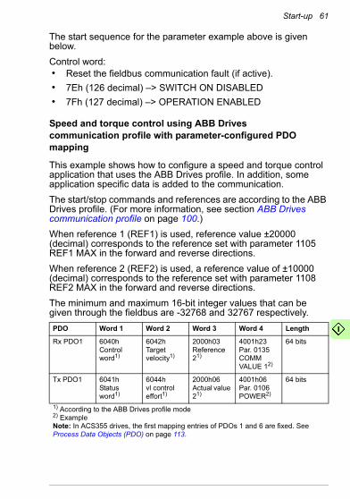
The start sequence for the parameter example above is given below.Control word:• Reset the fieldbus communication fault (if active).• 7Eh (126 decimal) –> SWITCH ON DISABLED• 7Fh (127 decimal) –> OPERATION ENABLED
Speed and torque control using ABB Drivescommunication profile with parameter-configured PDOmapping
This example shows how to configure a speed and torque control application that uses the ABB Drives profile. In addition, some application specific data is added to the communication.The start/stop commands and references are according to the ABB Drives profile. (For more information, see section ABB Drives communication profile on page 100.)When reference 1 (REF1) is used, reference value ±20000 (decimal) corresponds to the reference set with parameter 1105 REF1 MAX in the forward and reverse directions.When reference 2 (REF2) is used, a reference value of ±10000 (decimal) corresponds to the reference set with parameter 1108 REF2 MAX in the forward and reverse directions.The minimum and maximum 16-bit integer values that can be given through the fieldbus are -32768 and 32767 respectively.PDO Word 1 Word 2 Word 3 Word 4 Length
Rx PDO1 6040hControl word1)
6042hTarget velocity1)
2000h03Reference 21)
4001h23Par. 0135COMM VALUE 12)
64 bits
Tx PDO1 6041hStatus word1)
6044h vl control effort1)
2000h06 Actual value 21)
4001h06Par. 0106 POWER2)
64 bits
1) According to the ABB Drives profile mode2) ExampleNote: In ACS355 drives, the first mapping entries of PDOs 1 and 6 are fixed. See Process Data Objects (PDO) on page 113.
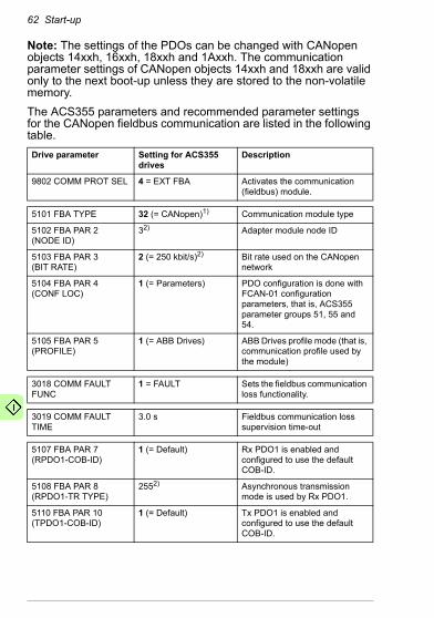
62 Start-up
Note: The settings of the PDOs can be changed with CANopen objects 14xxh, 16xxh, 18xxh and 1Axxh. The communication parameter settings of CANopen objects 14xxh and 18xxh are valid only to the next boot-up unless they are stored to the non-volatile memory.The ACS355 parameters and recommended parameter settings for the CANopen fieldbus communication are listed in the following table.Drive parameter Setting for ACS355
drivesDescription
9802 COMM PROT SEL 4 = EXT FBA Activates the communication (fieldbus) module.
5101 FBA TYPE 32 (= CANopen)1) Communication module type
5102 FBA PAR 2(NODE ID)
32) Adapter module node ID
5103 FBA PAR 3(BIT RATE)
2 (= 250 kbit/s)2) Bit rate used on the CANopen network
5104 FBA PAR 4(CONF LOC)
1 (= Parameters) PDO configuration is done with FCAN-01 configuration parameters, that is, ACS355 parameter groups 51, 55 and 54.
5105 FBA PAR 5(PROFILE)
1 (= ABB Drives) ABB Drives profile mode (that is, communication profile used by the module)
3018 COMM FAULT FUNC
1 = FAULT Sets the fieldbus communication loss functionality.
3019 COMM FAULT TIME
3.0 s Fieldbus communication loss supervision time-out
5107 FBA PAR 7 (RPDO1-COB-ID)
1 (= Default) Rx PDO1 is enabled and configured to use the default COB-ID.
5108 FBA PAR 8 (RPDO1-TR TYPE)
2552) Asynchronous transmission mode is used by Rx PDO1.
5110 FBA PAR 10 (TPDO1-COB-ID)
1 (= Default) Tx PDO1 is enabled and configured to use the default COB-ID.
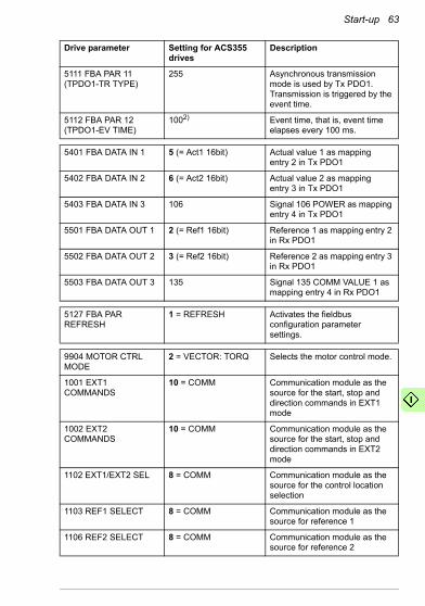
Start-up 63
5111 FBA PAR 11 (TPDO1-TR TYPE)
255 Asynchronous transmission mode is used by Tx PDO1. Transmission is triggered by the event time.
5112 FBA PAR 12 (TPDO1-EV TIME)
1002) Event time, that is, event time elapses every 100 ms.
5401 FBA DATA IN 1 5 (= Act1 16bit) Actual value 1 as mapping entry 2 in Tx PDO1
5402 FBA DATA IN 2 6 (= Act2 16bit) Actual value 2 as mapping entry 3 in Tx PDO1
5403 FBA DATA IN 3 106 Signal 106 POWER as mapping entry 4 in Tx PDO1
5501 FBA DATA OUT 1 2 (= Ref1 16bit) Reference 1 as mapping entry 2 in Rx PDO1
5502 FBA DATA OUT 2 3 (= Ref2 16bit) Reference 2 as mapping entry 3 in Rx PDO1
5503 FBA DATA OUT 3 135 Signal 135 COMM VALUE 1 as mapping entry 4 in Rx PDO1
5127 FBA PAR REFRESH
1 = REFRESH Activates the fieldbus configuration parameter settings.
9904 MOTOR CTRL MODE
2 = VECTOR: TORQ Selects the motor control mode.
1001 EXT1 COMMANDS
10 = COMM Communication module as the source for the start, stop and direction commands in EXT1 mode
1002 EXT2 COMMANDS
10 = COMM Communication module as the source for the start, stop and direction commands in EXT2 mode
1102 EXT1/EXT2 SEL 8 = COMM Communication module as the source for the control location selection
1103 REF1 SELECT 8 = COMM Communication module as the source for reference 1
1106 REF2 SELECT 8 = COMM Communication module as the source for reference 2
Drive parameter Setting for ACS355 drives
Description

64 Start-up
The start sequence for the parameter example above is given below.Control word:• Reset the fieldbus communication fault (if active).• 47Eh (1150 decimal) –> READY TO SWITCH ON• 47Fh (1151 decimal) –> OPERATING (Speed mode)
orC7Fh (3199 decimal) –> OPERATING (Torque mode)
Starting up ACSM1 drives1. Power up the drive.
2. Enable the communication between the adapter module and the drive by setting parameter 50.01 FBA ENABLE to ENABLE.
3. With parameter 50.02 COMM LOSS FUNC, select how the drive reacts to a fieldbus communication break.Note: This function monitors both communication between the fieldbus master and adapter module and communication between the adapter module and drive.
4. With parameter 50.03 COMM LOSS T OUT, define the time between communication break detection and the selected action.
1601 RUN ENABLE 7 = COMM Communication module as the source for the Run enable signal
1604 FAULT RESET SEL
8 = COMM Communication module as the source for the fault reset signal
1) Automatically detected2) Example
Drive parameter Setting for ACS355 drives
Description
Start-up 65
5. Select application-specific values for parameters 50.04…50.11.Examples of appropriate values are shown in the tables below.
6. Set the FCAN-01 configuration parameters in parameter group 51.At minimum, set the required node address in parameter 51.02 NODE ID and the required bit rate in 51.03 BIT RATE, select the source of the PDO configuration in 51.04 CONF LOC and the communication profile in 51.05 PROFILE.
7. If group 51 is selected as the source for the PDO configuration, select the application specific configuration for the PDOs with parameters 51.07…51.24.
8. If group 51 is selected as the source for the PDO configuration, define the process data transferred to and from the drive in the FCAN-01 configuration parameter groups 52 and 53.Note: If the PDO configuration is written from the PLC, parameters 51.07…51.24 are not used and the parameter groups 52 and 53 display the process data selected in the PLC.
9. To validate the settings made in parameter groups 51, 52 and 53, set parameter 51.27 FBA PAR REFRESH to REFRESH.
10. Set the relevant drive control parameters to control the drive according to the application.See the parameter setting examples below.
66 Start-up
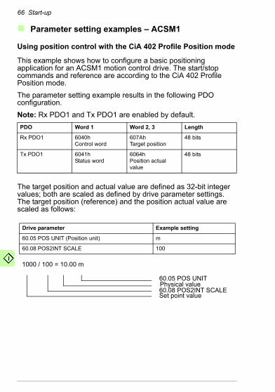
Parameter setting examples – ACSM1
Using position control with the CiA 402 Profile Position mode
This example shows how to configure a basic positioning application for an ACSM1 motion control drive. The start/stop commands and reference are according to the CiA 402 Profile Position mode.The parameter setting example results in the following PDO configuration.Note: Rx PDO1 and Tx PDO1 are enabled by default.
The target position and actual value are defined as 32-bit integer values; both are scaled as defined by drive parameter settings. The target position (reference) and the position actual value are scaled as follows:
PDO Word 1 Word 2, 3 Length
Rx PDO1 6040hControl word
607AhTarget position
48 bits
Tx PDO1 6041hStatus word
6064h Position actual value
48 bits
Drive parameter Example setting
60.05 POS UNIT (Position unit) m
60.08 POS2INT SCALE 100
1000 / 100 = 10.00 m
60.05 POS UNITPhysical value60.08 POS2INT SCALESet point value

Start-up 67
The ACSM1 parameters and recommended parameter settings for the CANopen fieldbus communication are listed in the following table.Drive parameter Setting for ACSM1
drivesDescription
50.01 FBA ENABLE Enable Activates the communication (fieldbus) module.
50.02 COMM LOSS FUNC
Fault Enables communication between the drive and the fieldbus adapter module.
50.03 COMM LOSS T OUT
1.0 s Defines the fieldbus communication break supervision time-out.
50.04 FBA REF1 MODESEL
Position Defines the fieldbus reference scaling.
51.01 FBA TYPE 32 (= CANopen)1) Communication module type
51.02 FBA PAR2 (NODE ID)
32) Adapter module node ID
51.03 FBA PAR3 (BIT RATE)
3 (= 125 kbit/s)2) Bit rate used on the CANopen network
51.04 FBA PAR4 (CONF LOC)
1 (= Parameters) PDO configuration is done with FCAN-01 configuration parameter group A (group 1), B (group 2) and C (group 3) (that is, ACSM1 parameter groups 51, 52 and 53).
51.05 FBA PAR5 (PROFILE)
0 (= CiA 402) CiA 402 communication profile (that is, communication profile used by the module)
51.08 FBA PAR8 (RPDO1-TR TYPE)
2552) Asynchronous transmission mode is used by Rx PDO1.
52.01 FBA DATA IN1 4 (= SW 16bit) Status word (16-bit) as mapping entry 1 in Tx PDO1
52.02 FBA DATA IN2 15 (= Act1 32bit) Position actual value (32-bit) as mapping entries 2 and 3 in Tx PDO1

68 Start-up
52.03 FBA DATA IN3 0 (reserved) Parameters in groups 52 and 53 are 16-bit parameters. Mapping of 32-bit parameters automatically reserves also the following cell (that is, the mapping of 15 to parameter 52.02 reserves also the parameter 52.03).
53.01 FBA DATA OUT1 1 (= CW 16bit) Control word (16-bit) as mapping entry 1 in Rx PDO1
53.02 FBA DATA OUT2 12 (= Ref1 32bit) Position Reference (32-bit) as mapping entries 2 and 3 in Rx PDO1
53.03 FBA DATA OUT3 0 (reserved) Parameters in groups 52 and 53 are16-bit parameters. Mapping of 32-bit parameters automatically reserves also the following cell (that is, the mapping of 12 to parameter 53.02 reserves also the parameter 53.03).
51.27 FBA PAR REFRESH
REFRESH Activates the fieldbus configuration parameter settings.
10.01 EXT1 START FUNC
FBA Communication module as the source for the start, stop and direction commands
34.03 EXT1 CTRL MODE 1
Position Selects the position control mode for external control location EXT1.
65.01 POS REFSOURCE
Ref table Reference and other positioning parameters are read from reference set 1/2.
65.04 POS REF 1 SEL FBA REF1 Fieldbus reference 1 is the source for the position reference when reference set 1 is used.
1) Automatically detected2) Example
Drive parameter Setting for ACSM1 drives
Description
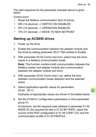
Start-up 69
The start sequence for the parameter example above is given below.Control word:• Reset the fieldbus communication fault (if active).• 0Eh (14 decimal) –> SWITCH ON DISABLED• 0Fh (15 decimal) –> OPERATION ENABLED• 1Fh (31 decimal) –> MOVE TO NEW SETPOINT
Starting up ACS850 drives1. Power up the drive.
2. Enable the communication between the adapter module and the drive by setting parameter 50.01 FBA enable to Enable.
3. With parameter 50.02 Comm loss func, select how the drive reacts to a fieldbus communication break.Note: This function monitors both communication between the fieldbus master and adapter module and communication between the adapter module and drive.
4. With parameter 50.03 Comm loss t out, define the time between communication break detection and the selected action.
5. Select application-specific values for parameters 50.04…50.11.Examples of appropriate values are shown in the tables below.
6. Set the FCAN-01 configuration parameters in drive parameter group 51.At minimum, set the required node address in parameter 51.02 NODE ID, the required bit rate in 51.03 BIT RATE, select the source of the PDO configuration in 51.04 CONF LOC and the communication profile in 51.05 PROFILE.

70 Start-up
7. If group 51 is selected as the source for the PDO configuration, select the application specific configuration for the PDOs with parameters 51.07…51.24.
8. Define the process data transferred to and from the drive in the FCAN-01 configuration parameter groups 52 and 53.Note: If the PDO configuration is witten from the PLC, parameters 51.07…51.24 are not used and the parameter groups 52 and 53 display the process data selected in the PLC.
9. To validate the settings made in parameter groups 51, 52 and 53, set parameter 51.27 FBA par refresh to Refresh.
10. Set the relevant drive control parameters to control the drive according to the application.See the parameter setting examples below.
Parameter setting examples – ACS850
CiA 402 Velocity mode with default PDO mapping
This example shows how to configure a basic speed control application that uses the CiA 402 profile. The start/stop commands are according to the CiA 402 profile velocity control mode.Rx PDO1 and Tx PDO1 are enabled by default.
Note: The Tx PDO1 default transmission type is 255 (asynchronous) and event time is 0. The event time should be changed with CANopen object 1800h05 if the default transmission type is used.
PDO Word 1 Length
Rx PDO1 6040h Control word 16 bits
Tx PDO1 6041h Status word 16 bits
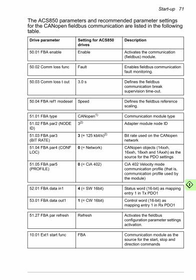
Start-up 71
The ACS850 parameters and recommended parameter settings for the CANopen fieldbus communication are listed in the following table.Drive parameter Setting for ACS850
drivesDescription
50.01 FBA enable Enable Activates the communication (fieldbus) module.
50.02 Comm loss func Fault Enables fieldbus communication fault monitoring.
50.03 Comm loss t out 3.0 s Defines the fieldbus communication break supervision time-out.
50.04 FBA ref1 modesel Speed Defines the fieldbus reference scaling.
51.01 FBA type CANopen1) Communication module type
51.02 FBA par2 (NODE ID)
32) Adapter module node ID
51.03 FBA par3(BIT RATE)
3 (= 125 kbit/s)2) Bit rate used on the CANopen network
51.04 FBA par4 (CONF LOC)
0 (= Network) CANopen objects (14xxh, 16xxh, 18xxh and 1Axxh) as the source for the PDO settings
51.05 FBA par5 (PROFILE)
0 (= CiA 402) CiA 402 Velocity mode communication profile (that is, communication profile used by the module)
52.01 FBA data in1 4 (= SW 16bit) Status word (16-bit) as mapping entry 1 in Tx PDO1
53.01 FBA data out1 1 (= CW 16bit) Control word (16-bit) as mapping entry 1 in Rx PDO1
51.27 FBA par refresh Refresh Activates the fieldbus configuration parameter settings activation.
10.01 Ext1 start func FBA Communication module as the source for the start, stop and direction commands

72 Start-up
The start sequence for the parameter example above is given below.Control word:• Reset the fieldbus communication fault (if active).• 7Eh (126 decimal) –> SWITCH ON DISABLED• 7Fh (127 decimal) –> OPERATION ENABLED
ABB Drives communication profile with parameter-configured PDO mapping
This example shows how to configure a speed control application that uses the ABB drives profile.The start/stop commands and references are according to the ABB Drives profile. (For more information, see section ABB Drives communication profile on page 100.)Reference 1 (REF1) value ±20000 (decimal) corresponds to the reference set with parameter 19.01 (Speed scaling) in the forward and reverse directions.The minimum and maximum 16-bit integer values that can be given through the fieldbus are -32768 and 32767 respectively.
12.03 Ext1 ctrl mode Speed Selects the speed control mode for external control location EXT1.
21.01 Speed ref1 sel AI1 scaled2)
(Parameter 02.05)Analog input as the source for reference 1
1) Automatically detected2) Example
PDO Word 1 Word 2 Length
Rx PDO1 6040hControl word
6042hTarget velocity
32 bits
Tx PDO1 6041hStatus word
6044h vl control effort
32 bits
Drive parameter Setting for ACS850 drives
Description
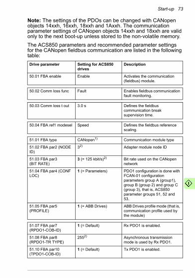
Start-up 73
Note: The settings of the PDOs can be changed with CANopen objects 14xxh, 16xxh, 18xxh and 1Axxh. The communication parameter settings of CANopen objects 14xxh and 18xxh are valid only to the next boot-up unless stored to the non-volatile memory.The ACS850 parameters and recommended parameter settings for the CANopen fieldbus communication are listed in the following table:Drive parameter Setting for ACS850
drivesDescription
50.01 FBA enable Enable Activates the communication (fieldbus) module.
50.02 Comm loss func Fault Enables fieldbus communication fault monitoring.
50.03 Comm loss t out 3.0 s Defines the fieldbus communication break supervision time.
50.04 FBA ref1 modesel Speed Defines the fieldbus reference scaling.
51.01 FBA type CANopen1) Communication module type
51.02 FBA par2 (NODE ID)
32) Adapter module node ID
51.03 FBA par3(BIT RATE)
3 (= 125 kbit/s)2) Bit rate used on the CANopen network
51.04 FBA par4 (CONF LOC)
1 (= Parameters) PDO1 configuration is done with FCAN-01 configuration parameters group A (group1), group B (group 2) and group C (group 3), that is, ACS850 parameter groups 51, 52 and 53.
51.05 FBA par5 (PROFILE)
1 (= ABB Drives) ABB Drives profile mode (that is, communication profile used by the module)
51.07 FBA par7 (RPDO1-COB-ID)
1 (= Default) Rx PDO1 is enabled.
51.08 FBA par8 (RPDO1-TR TYPE)
2552) Asynchronous transmission mode is used by Rx PDO1.
51.10 FBA par10 (TPDO1-COB-ID)
1 (= Default) Tx PDO1 is enabled.
74 Start-up
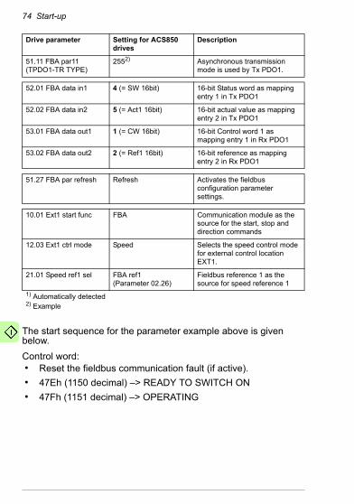
The start sequence for the parameter example above is given below.Control word:• Reset the fieldbus communication fault (if active).• 47Eh (1150 decimal) –> READY TO SWITCH ON• 47Fh (1151 decimal) –> OPERATING
51.11 FBA par11 (TPDO1-TR TYPE)
2552) Asynchronous transmission mode is used by Tx PDO1.
52.01 FBA data in1 4 (= SW 16bit) 16-bit Status word as mapping entry 1 in Tx PDO1
52.02 FBA data in2 5 (= Act1 16bit) 16-bit actual value as mapping entry 2 in Tx PDO1
53.01 FBA data out1 1 (= CW 16bit) 16-bit Control word 1 as mapping entry 1 in Rx PDO1
53.02 FBA data out2 2 (= Ref1 16bit) 16-bit reference as mapping entry 2 in Rx PDO1
51.27 FBA par refresh Refresh Activates the fieldbus configuration parameter settings.
10.01 Ext1 start func FBA Communication module as the source for the start, stop and direction commands
12.03 Ext1 ctrl mode Speed Selects the speed control mode for external control location EXT1.
21.01 Speed ref1 sel FBA ref1(Parameter 02.26)
Fieldbus reference 1 as the source for speed reference 1
1) Automatically detected2) Example
Drive parameter Setting for ACS850 drives
Description

Start-up 75
Starting up ACS880 drives1. Power up the drive.
2. Enable the communication between the adapter module and the drive by setting parameter 50.01 FBA A enable to Enable.
3. With parameter 50.02 FBA A comm loss func, select how the drive reacts to a fieldbus communication break.Note: This function monitors both communication between the fieldbus master and adapter module and communication between the adapter module and drive.
4. With parameter 50.03 FBA A comm loss t out, define the time between communication break detection and the selected action.
5. Select application-specific values for parameters 50.04…50.11. Examples of appropriate values are shown in the tables below.
6. Set the FCAN-01 configuration parameters in drive parameter group 51.At minimum, set the required node address in parameter 51.02 Node ID, the required bit rate in 51.03 Bit rate, select source of the PDO configuration in 51.04 Conf location and the communication profile in 51.05 Profile.
7. If the group 51 is selected as the source for the PDO configuration, select the application specific configuration for the PDOs with parameters 51.07…51.24.
8. Define the process data transferred to and from the drive in the FCAN-01 configuration parameter groups 52 and 53.Note: If the PDO configuration is written from the PLC, the parameters 51.07…51.24 are not used and the parameter groups 52 and 53 display the process data selected in the PLC.
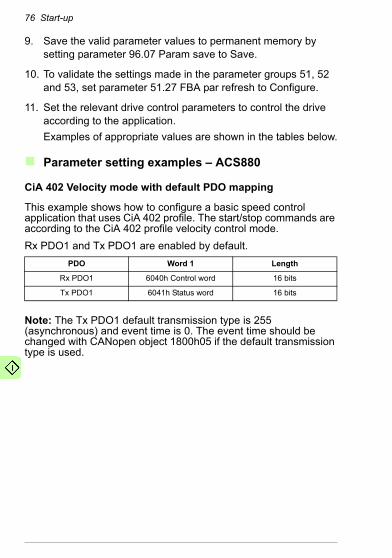
76 Start-up
9. Save the valid parameter values to permanent memory by setting parameter 96.07 Param save to Save.
10. To validate the settings made in the parameter groups 51, 52 and 53, set parameter 51.27 FBA par refresh to Configure.
11. Set the relevant drive control parameters to control the drive according to the application.Examples of appropriate values are shown in the tables below.
Parameter setting examples – ACS880
CiA 402 Velocity mode with default PDO mapping
This example shows how to configure a basic speed control application that uses CiA 402 profile. The start/stop commands are according to the CiA 402 profile velocity control mode.Rx PDO1 and Tx PDO1 are enabled by default.
Note: The Tx PDO1 default transmission type is 255 (asynchronous) and event time is 0. The event time should be changed with CANopen object 1800h05 if the default transmission type is used.
PDO Word 1 Length
Rx PDO1 6040h Control word 16 bits
Tx PDO1 6041h Status word 16 bits

Start-up 77
The ACS880 parameters and recommended parameter settings for the CANopen fieldbus communication are listed in the following table.Drive parameter Setting for ACS880
drivesDescription
50.01 FBA A enable 1 = Enable Enables communication between the drive and the fieldbus adapter module.
50.02 FBA A comm loss func
1 = Fault Enables fieldbus communication fault monitoring.
50.03 FBA A comm loss t out
3.0 s Defines the fieldbus communication break supervision time.
50.04 FBA A ref1 type 4 = Speed Defines the fieldbus A reference 1 scaling.
51.01 FBA type CANopen1) Communication module type
51.02 Node ID 32) Adapter module node ID
51.03 Bit rate 3 = 125 kbit/s2) Bit rate used on the CANopen network
51.04 Conf location 0 = Network CANopen objects (14xxh, 16xxh, 18xxh and 1Axxh) as the source for the PDO settings
51.05 Profile 0 = CiA 402 CiA 402 Velocity mode communication profile (that is, communication profile used by the module)
52.01 FBA data in1 4 = SW 16bit2) 16-bit Status word as mapping entry 1 in Tx PDO1
53.01 FBA data out1 1 = CW 16bit2) 16-bit Control word 1 as mapping entry 1 in Rx PDO1
51.27 FBA par refresh 1 = Configure Activates the fieldbus configuration parameter settings.
19.12 Ext1 control mode 1
2 = Speed Selects speed control as control mode 1 for external control location 1.
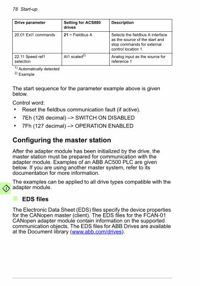
78 Start-up
The start sequence for the parameter example above is given below.Control word:• Reset the fieldbus communication fault (if active).• 7Eh (126 decimal) –> SWITCH ON DISABLED• 7Fh (127 decimal) –> OPERATION ENABLED
Configuring the master stationAfter the adapter module has been initialized by the drive, the master station must be prepared for communication with the adapter module. Examples of an ABB AC500 PLC are given below. If you are using another master system, refer to its documentation for more information.The examples can be applied to all drive types compatible with the adapter module.
EDS filesThe Electronic Data Sheet (EDS) files specify the device properties for the CANopen master (client). The EDS files for the FCAN-01 CANopen adapter module contain information on the supported communication objects. The EDS files for ABB Drives are available at the Document library (www.abb.com/drives).
20.01 Ext1 commands 21 = Fieldbus A Selects the fieldbus A interface as the source of the start and stop commands for external control location 1.
22.11 Speed ref1 selection
AI1 scaled2) Analog input as the source for reference 1
1) Automatically detected2) Example
Drive parameter Setting for ACS880 drives
Description

Start-up 79
Configuring an ABB AC500 PLCThis example shows how to configure the communication between an AC500 PLC and the adapter module using the Control Builder Plus PS501 software version 2.1.0 and later.Before you start, make sure that you have downloaded the FCAN-01 EDS description file from the Document library.1. Start the ABB Control Builder software.
2. On the Tools menu, select Device Repository.
3. In the opening window, click Install and browse for the EDS file downloaded from the Document library.

80 Start-up
4. Open or create the PLC project that is used to control the drive.
5. Add the CM578-CN CANopen master device to the PLC project if necessary.
6. Add the adapter module/drive to the CANopen network.
7. Configure the master properties such as baud rate, node ID and heartbeat.
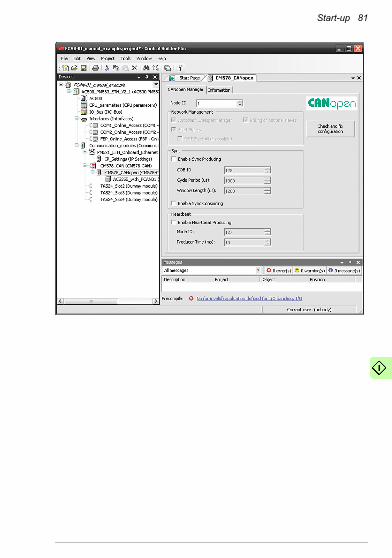
Start-up 81
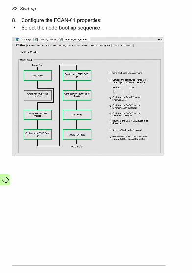
82 Start-up
8. Configure the FCAN-01 properties:• Select the node boot up sequence.
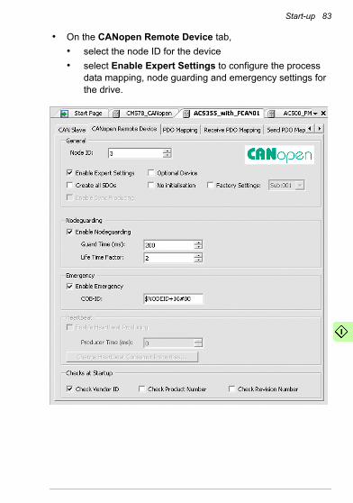
Start-up 83
• On the CANopen Remote Device tab,• select the node ID for the device• select Enable Expert Settings to configure the process
data mapping, node guarding and emergency settings for the drive.

84 Start-up
• On the PDO Mapping tab, select the PDOs transferred between the PLC and the drive.
• On the Receive PDO Mapping tab, select the variables transferred from PLC to drive.

Start-up 85
• On the Send PDO Mapping tab, select the variables transferred from drive to PLC.
• On the Service Data Object tab, define the parameter values that are sent to the drive when the communication is initialized.
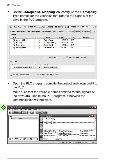
86 Start-up
• On the CANopen I/O Mapping tab, configure the I/O mapping. Type names for the variables that refer to the signals of the drive in the PLC program.
• Open the PLC program, compile the project and download it to the PLC.Make sure that the variable names defined for the signals of the drive are used in the PLC program, otherwise the communication will not work.

Communication profiles 87
7Communication profiles
What this chapter containsThis chapter describes the communication profiles used in communication between the CANopen network, the adapter module and the drive.
Communication profilesCommunication profiles are ways of conveying control commands (Control word, Status word, references and actual values) between the master station and the drive.With the FCAN-01 CANopen adapter module, the CANopen network may employ the CiA 402 profile (Device profile for drives and motion control) or the ABB Drives profile. Both are converted to the native profile (for example, DCU or FBA, detailed in the drive manuals) by the adapter module. In addition, two Transparent profiles – for 16-bit and 32-bit words respectively – are available. With the Transparent modes, no data conversion takes place.Note: The CiA 402 operation mode support is drive-specific. See CANopen device profile CiA 402 on page 89 for more details.The profile is selected from the drive with parameter 05 PROFILE of the fieldbus configuration group A. For example, if parameter 05 PROFILE is set to 0, the Control word of the drive is set according to the CiA 402 specification.
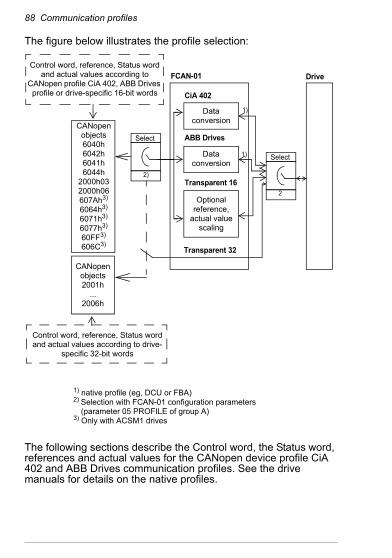
88 Communication profiles
The figure below illustrates the profile selection:
The following sections describe the Control word, the Status word, references and actual values for the CANopen device profile CiA 402 and ABB Drives communication profiles. See the drive manuals for details on the native profiles.
Data conversion
CiA 402
FCAN-01
ABB Drives
Transparent 16
Transparent 32
Drive
Optional reference,
actual value scaling
1)
1)
CANopen objects2001h
...2006h
CANopen objects6040h6042h6041h6044h
2000h032000h06607Ah3)
6064h3)
6071h3)
6077h3)
60FF3)
606C3)
Control word, reference, Status word and actual values according to
CANopen profile CiA 402, ABB Drives profile or drive-specific 16-bit words
Data conversion
Select
2)
Control word, reference, Status word and actual values according to drive-
specific 32-bit words
Select
2
1) native profile (eg, DCU or FBA)2) Selection with FCAN-01 configuration parameters
(parameter 05 PROFILE of group A)3) Only with ACSM1 drives
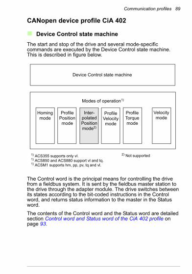
Communication profiles 89
CANopen device profile CiA 402
Device Control state machineThe start and stop of the drive and several mode-specific commands are executed by the Device Control state machine. This is described in figure below.
The Control word is the principal means for controlling the drive from a fieldbus system. It is sent by the fieldbus master station to the drive through the adapter module. The drive switches between its states according to the bit-coded instructions in the Control word, and returns status information to the master in the Status word.The contents of the Control word and the Status word are detailed section Control word and Status word of the CiA 402 profile on page 93.
Homing mode
Profile Position mode
Inter-polated Position mode2)
Profile Velocity mode
Profile Torque mode
Velocity mode
2) Not supported1) ACS355 supports only vl.1) ACS850 and ACS880 support vl and tq.1) ACSM1 supports hm, pp, pv, tq and vl.
Device Control state machine
Modes of operation1)

90 Communication profiles
Modes of operationThe operation mode defines the behavior of the drive. CiA 402 defines following operation modes:• Homing mode• Profile position mode• Interpolated position mode• Profile velocity mode• Profile torque mode• Velocity mode
The FCAN-01 CANopen adapter module supports minimal implementation of the operation modes. Operation mode support is drive-specific (see the figure at the beginning of this chapter). The interpolated position mode is not supported.In this chapter scalings of the reference and actual values are described for each operation mode. Operation-mode-specific objects are defined in section CANopen Object Dictionary on page 131.In ACSM1 drives, the mode of operation is automatically selected according to the control mode configured with parameter 34.03 EXT1 CTRL MODE, 34.04 EXT1 CTRL MODE2 or 34.05 EXT2 CTRL MODE1 (depending on the current control location). The correct reference scaling must be selected with parameter 50.04 FBA REF1 MODESEL.If the value of parameter 50.04 FBA REF1 MODESEL and 50.05 FBA REF2 MODESEL of ACSM1 is (5) AUTO, it is possible to set the mode of operation with object 6060h. For more information, see section Standardized device profile area (6000...9FFF) on page 145.
Homing modeHoming mode describes various methods of finding a home position, or zero point. Either limit switches at the ends of travel or a home switch in mid travel are used. Most of the methods also use the index (zero) pulse from an encoder. For more information on the homing mode and descriptions of the various homing methods, see the drive manual.
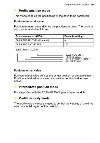
Communication profiles 91
Profile position modeThis mode enables the positioning of the drive to be controlled.
Position demand value
Position demand value defines the position set point. The position set point is scaled as follows:
Position actual value
Position actual value defines the actual position of the application. Position actual value is scaled as position demand value (see above).
Interpolated position modeNot supported with the FCAN-01 CANopen adapter module.
Profile velocity modeThe profile velocity mode is used to control the velocity of the drive with no special regard of the position.
Drive parameter (ACSM1) Example setting60.05 POS UNIT (Position unit) m
60.08 POS2INT SCALE 100
1000 / 100 = 10.00 m
60.05 POS UNITPhysical value60.08 POS2INT SCALESet point value
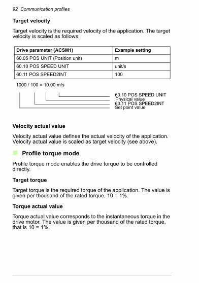
92 Communication profiles
Target velocity
Target velocity is the required velocity of the application. The target velocity is scaled as follows:
Velocity actual value
Velocity actual value defines the actual velocity of the application. Velocity actual value is scaled as target velocity (see above).
Profile torque modeProfile torque mode enables the drive torque to be controlled directly.
Target torque
Target torque is the required torque of the application. The value is given per thousand of the rated torque, 10 = 1%.
Torque actual value
Torque actual value corresponds to the instantaneous torque in the drive motor. The value is given per thousand of the rated torque, that is 10 = 1%.
Drive parameter (ACSM1) Example setting60.05 POS UNIT (Position unit) m
60.10 POS SPEED UNIT unit/s
60.11 POS SPEED2INT 100
1000 / 100 = 10.00 m/s
60.10 POS SPEED UNITPhysical value60.11 POS SPEED2INTSet point value
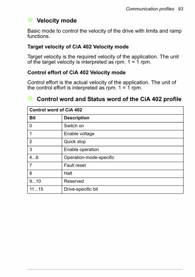
Communication profiles 93
Velocity modeBasic mode to control the velocity of the drive with limits and ramp functions.
Target velocity of CiA 402 Velocity mode
Target velocity is the required velocity of the application. The unit of the target velocity is interpreted as rpm. 1 = 1 rpm.
Control effort of CiA 402 Velocity mode
Control effort is the actual velocity of the application. The unit of the control effort is interpreted as rpm. 1 = 1 rpm.
Control word and Status word of the CiA 402 profile
Control word of CiA 402Bit Description0 Switch on
1 Enable voltage
2 Quick stop
3 Enable operation
4...6 Operation-mode-specific
7 Fault reset
8 Halt
9...10 Reserved
11...15 Drive-specific bit

94 Communication profiles
Operation-mode-specific bitsBit Velocity
modeProfile position mode1)
Profile velocity mode1)
Profile torque mode2)
Homing mode1)
Interpo-lated position mode3)
4 rfg enable
New setpoint
Reserved Reserved Homing operation start
Enable ipmode
5 rfg unlock Change set immedi-ately
Reserved Reserved Reserved Reserved
6 rfg use ref
abs / rel Reserved Reserved Reserved Reserved
1) Supported with ACSM1 only2) Supported with ACSM1, ACS850 and ACS880 only3) Not supported
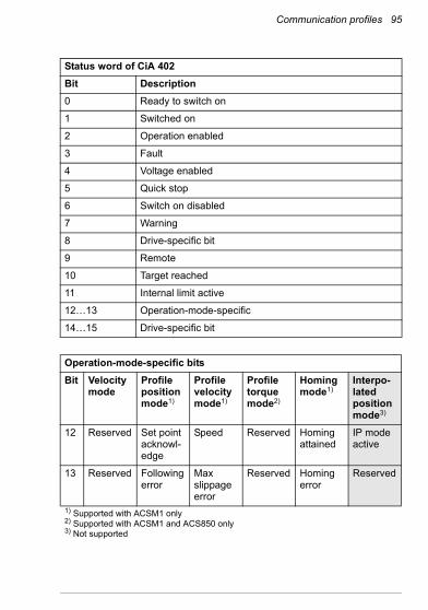
Communication profiles 95
Status word of CiA 402Bit Description0 Ready to switch on
1 Switched on
2 Operation enabled
3 Fault
4 Voltage enabled
5 Quick stop
6 Switch on disabled
7 Warning
8 Drive-specific bit
9 Remote
10 Target reached
11 Internal limit active
12…13 Operation-mode-specific
14…15 Drive-specific bit
Operation-mode-specific bitsBit Velocity
modeProfile position mode1)
Profile velocity mode1)
Profile torque mode2)
Homing mode1)
Interpo-lated position mode3)
12 Reserved Set point acknowl-edge
Speed Reserved Homing attained
IP mode active
13 Reserved Following error
Max slippage error
Reserved Homing error
Reserved
1) Supported with ACSM1 only2) Supported with ACSM1 and ACS850 only3) Not supported

96 Communication profiles
Device control commands are triggered by the Control word bits as follows:
Device control commandsCommand Control word bit
Fault reset, bit 7
Enable operation,bit 3
Quick stop,bit 2
Enable voltage,bit 1
Switch on,bit 0
State transi-tions*
Shut down 0 x 1 1 0 2, 6, 8
Switch on 0 0 1 1 1 31)
Switch on 0 1 1 1 1 31)
Disable voltage 0 x x 0 x 7, 9, 10,
12
Quick stop 0 x 0 1 x 7, 10, 11
Disable operation 0 0 1 1 1 5
Enable operation 0 1 1 1 1 4
Fault reset x x x x 15
Bits marked with x are irrelevant.1) When Control word bit 3 (Enable operation) is 1, the drive does not perform any
tasks in the SWITCHED ON state. When bit 3 is 0, state SWITCHED ON tasks are performed. See the Device Control state machine figure on page 89.
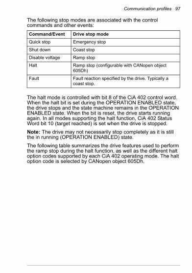
Communication profiles 97
The following stop modes are associated with the control commands and other events:
The halt mode is controlled with bit 8 of the CiA 402 control word. When the halt bit is set during the OPERATION ENABLED state, the drive stops and the state machine remains in the OPERATION ENABLED state. When the bit is reset, the drive starts running again. In all modes supporting the halt function, CiA 402 Status Word bit 10 (target reached) is set when the drive is stopped.Note: The drive may not necessarily stop completely as it is still the in running (OPERATION ENABLED) state.The following table summarizes the drive features used to perform the ramp stop during the halt function, as well as the different halt option codes supported by each CiA 402 operating mode. The halt option code is selected by CANopen object 605Dh.
Command/Event Drive stop modeQuick stop Emergency stop
Shut down Coast stop
Disable voltage Ramp stop
Halt Ramp stop (configurable with CANopen object 605Dh)
Fault Fault reaction specified by the drive. Typically a coast stop.

98 Communication profiles
Mode Description Halt option codesProfile Position Dynamic limiter ramp 1
Interpolated Position Dynamic limiter ramp 1
Profile Velocity Dynamic limiter ramp 1
Profile Torque Sets the torque reference to 0. Ramp depends on drive parameters.
1
Homing Dynamic limiter ramp 1
Velocity Halt mode 1: Ramp input is set to 0.Halt mode 2,3,4: Ramp output is set to 0.
1, 2, 3, 4
Other modes Halt bit has no effect. N/A

Communication profiles 99
State machine
The following figure describes the CANopen state machine.
CW: xxxxxxxx1xxxxxxx
From any state
FAULT REACTIONACTIVE
SW: xxxxxxxxx0xx1111
Fault reactioncompleted
FAULTSW: xxxxxxxxx0xx1000
START
Power-on,self-initialization
NOT READYSW: xxxxxxxxx0xx0000
TO SWITCH ON
Initializedsuccessfully
CW: xxxxxxxxxxxxx01xCW: xxxxxxxxxxxxx110
CW: xxxxxxxxxxxxx110
CW: xxxxxxxxxxxxx111
CW: xxxxxxxxxxxxx01xor
CW: xxxxxxxxxxxxxx0x
CW: xxxxxxxxxxxx0111
CW: xxxxxxxxxxxx1111
CW: xxxxxxxxxxxxx110
Quick stopcompleted
CW: xxxxxxxxxxxxx01xCW: xxxxxxxxxxxxxx0x
CW: Control wordSW: Status word
SWITCH-ONSW: xxxxxxxxx1xx0000
DISABLED
SWITCHED ONSW: xxxxxxxxx01x0011
READY TO
SW: xxxxxxxxx01x0001SWITCH ON
OPERATIONSW: xxxxxxxxx01x0111
ENABLEDQUICK STOP
SW: xxxxxxxxx0xx0111ACTIVE
orCW: xxxxxxxxxxxxxx0x
orCW: xxxxxxxxxxxxxx0x
State transition(0)
(1) (15)
(2)
(7)
(3)
(6)
(10)
(12)
(9)
(8)
(5)
(4)
(11)
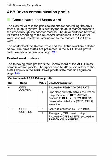
100 Communication profiles
ABB Drives communication profile
Control word and Status wordThe Control word is the principal means for controlling the drive from a fieldbus system. It is sent by the fieldbus master station to the drive through the adapter module. The drive switches between its states according to the bit-coded instructions in the Control word, and returns status information to the master in the Status word.The contents of the Control word and the Status word are detailed below. The drive states are presented in the ABB Drives profile state transition diagram on page 105.
Control word contents
The following table presents the Control word of the ABB Drives communication profile. The upper case boldface text refers to the states shown in the ABB Drives profile state machine figure on page 105.
Control word of ABB Drives profileBit Name Value STATE/Description0 OFF1_
CONTROL1 Proceed to READY TO OPERATE.
0 Stop along currently active deceleration ramp. Proceed to OFF1 ACTIVE; proceed to READY TO SWITCH ON unless other interlocks (OFF2, OFF3) are active.
1 OFF2_CONTROL
1 Continue operation (OFF2 inactive).
0 Emergency OFF; coast to stop.Proceed to OFF2 ACTIVE, proceed to SWITCH-ON INHIBITED.

Communication profiles 101
2 OFF3_CONTROL
1 Continue operation (OFF3 inactive).
0 Emergency stop; stop within time defined with the drive parameter. Proceed to OFF3 ACTIVE; proceed to SWITCH-ON INHIBITED.Warning: Ensure motor and driven machine can be stopped using this stop mode.
3 INHIBIT_OPERATION
1 Proceed to OPERATION ENABLED.Note: Run enable signal must be active; see the drive manuals. If the drive is set to receive the Run enable signal from the fieldbus, this bit activates the signal.
0 Inhibit operation; proceed to OPERATION INHIBITED.
4 RAMP_OUT_ZERO
1 Normal operation; proceed to RFG: OUTPUT ENABLED.
0 Force the Ramp Function Generator output to zero. The drive ramps to stop (current and DC voltage limits in force).
5 RAMP_HOLD 1 Enable the ramp function;proceed to RFG: ACCELERATOR ENABLED.
0 Halt ramping (the Ramp Function Generator output held).
6 RAMP_IN_ZERO
1 Normal operation; proceed to OPERATION.Note: Effective only if the fieldbus interface is set as the source for this signal with drive parameters.
0 Force the Ramp Function Generator input to zero.
Control word of ABB Drives profileBit Name Value STATE/Description
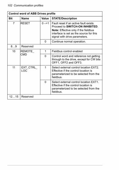
102 Communication profiles
7 RESET 0 –>1 Fault reset if an active fault exists. Proceed to SWITCH-ON INHIBITED.Note: Effective only if the fieldbus interface is set as the source for this signal with drive parameters.
0 Continue normal operation.
8…9 Reserved
10 REMOTE_CMD
1 Fieldbus control enabled
0 Control word and reference not getting through to the drive, except for CW bits OFF1, OFF2 and OFF3.
11 EXT_CTRL_LOC
1 Select external control location EXT2. Effective if the control location is parameterized to be selected from the fieldbus.
0 Select external control location EXT1. Effective if the control location is parameterized to be selected from the fieldbus.
12…15 Reserved
Control word of ABB Drives profileBit Name Value STATE/Description
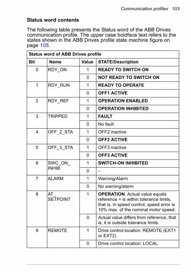
Communication profiles 103
Status word contents
The following table presents the Status word of the ABB Drives communication profile. The upper case boldface text refers to the states shown in the ABB Drives profile state machine figure on page 105.
Status word of ABB Drives profileBit Name Value STATE/Description
0 RDY_ON 1 READY TO SWITCH ON0 NOT READY TO SWITCH ON
1 RDY_RUN 1 READY TO OPERATE0 OFF1 ACTIVE
2 RDY_REF 1 OPERATION ENABLED0 OPERATION INHIBITED
3 TRIPPED 1 FAULT0 No fault
4 OFF_2_STA 1 OFF2 inactive
0 OFF2 ACTIVE5 OFF_3_STA 1 OFF3 inactive
0 OFF3 ACTIVE6 SWC_ON_
INHIB1 SWITCH-ON INHIBITED0 –
7 ALARM 1 Warning/Alarm
0 No warning/alarm
8 AT_SETPOINT
1 OPERATION. Actual value equals reference = is within tolerance limits, that is, in speed control, speed error is 10% max. of the nominal motor speed.
0 Actual value differs from reference, that is, it is outside tolerance limits.
9 REMOTE 1 Drive control location: REMOTE (EXT1 or EXT2)
0 Drive control location: LOCAL

104 Communication profiles
10 ABOVE_LIMIT
1 Actual frequency or speed equals or exceeds the supervision limit (set with the drive parameter). Valid in both directions of rotation.
0 Actual frequency or speed within supervision limit
11 EXT_CTRL_LOC
1 External Control Location EXT2 selectedNote concerning ACS880: This bit is effective only if the fieldbus interface is set as the target for this signal by drive parameters. User bit 0 selection (06.33).
0 External Control Location EXT1 selected
12 EXT_RUN_ENABLE
1 External Run Enable signal receivedNote concerning ACS880: This bit is effective only if the fieldbus interface is set as the target for this signal by drive parameters. User bit 1 selection (06.34).
0 No External Run Enable signal received
13…14 Reserved
15 FBA_ERROR 1 Communication error detected by the fieldbus adapter module.
0 Fieldbus adapter communication OK
Status word of ABB Drives profileBit Name Value STATE/Description
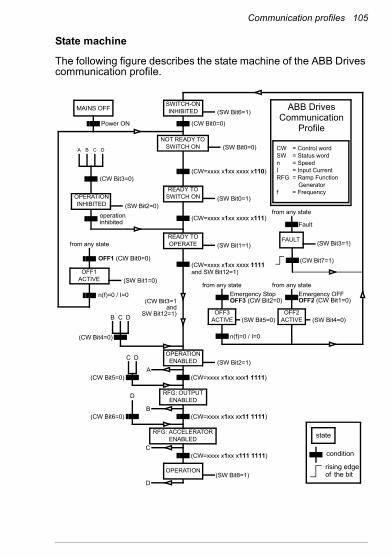
Communication profiles 105
State machine
The following figure describes the state machine of the ABB Drives communication profile.
MAINS OFF
Power ON (CW Bit0=0)
(SW Bit6=1)
(SW Bit0=0)
from any state
(CW=xxxx x1xx xxxx x110)
(SW Bit1=1)
n(f)=0 / I=0
(SW Bit2=0)
A B C D
(CW Bit3=0)
operationinhibited
OFF1 (CW Bit0=0)
(SW Bit1=0)
(SW Bit0=1)
(CW Bit3=1and
SW Bit12=1)
C D
(CW Bit5=0)
(SW Bit2=1)
(SW Bit5=0)
from any state from any stateEmergency StopOFF3 (CW Bit2=0)
n(f)=0 / I=0
Emergency OFFOFF2 (CW Bit1=0)
(SW Bit4=0)
B
B C D
(CW Bit4=0)
(CW=xxxx x1xx xxx1 1111)
(CW=xxxx x1xx xx11 1111)
D
(CW Bit6=0)
A
C(CW=xxxx x1xx x111 1111)
(SW Bit8=1)D
from any state
Fault
(SW Bit3=1)
(CW Bit7=1)
(CW=xxxx x1xx xxxx x111)
(CW=xxxx x1xx xxxx 1111and SW Bit12=1)
ABB DrivesCommunication
Profile
SWITCH-ON INHIBITED
NOT READY TO SWITCH ON
READY TO SWITCH ON
READY TO OPERATE
OPERATION INHIBITED
OFF1 ACTIVE
OPERATION ENABLED
RFG: OUTPUT ENABLED
RFG: ACCELERATOR ENABLED
OPERATION
OFF2 ACTIVE
FAULT
OFF3 ACTIVE
state
condition
rising edgethe bitof
CW = Control wordSW = Status wordn = SpeedI = Input CurrentRFG = Ramp Function
Generatorf = Frequency
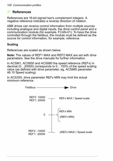
106 Communication profiles
ReferencesReferences are 16-bit signed two's complement integers. A negative reference indicates a reverse direction of rotation.ABB drives can receive control information from multiple sources including analogue and digital inputs, the drive control panel and a communication module (for example, FCAN-01). To have the drive controlled through the fieldbus, the module must be defined as the source for control information, for example, reference.
Scaling
References are scaled as shown below.Note: The values of REF1 MAX and REF2 MAX are set with drive parameters. See the drive manuals for further information.In ACSM1, ACS850 and ACS880 the speed reference (REFx) in decimal (0…20000) corresponds to 0…100% of the speed scaling value (as defined with drive parameter, eg, ACS880 parameter 46.10 Speed scaling).In ACS355, drive parameter REFx MIN may limit the actual minimum reference.
Fieldbus Drive
REF2: 10000REF1: 20000
0
REF2: -10000REF1: -20000
REFx MAX / Speed scale
REFx MIN
-(REFx MIN)
-(REFx MAX) / Speed scale

Communication profiles 107
Actual valuesActual values are 16-bit signed two's complement integers containing information on the operation of the drive. A negative reference indicates a reverse direction of rotation. The functions to be monitored are selected with a drive parameter.
Scaling
The actual values are scaled as shown below.Note: The values of REF1 MAX and REF2 MAX are set with drive parameters. See the drive manuals for further information.
Fieldbus Drive
ACT2: 10000ACT1: 20000
0
ACT2: -10000ACT1: -20000
REFx MAX
0
-(REFx MAX)

108 Communication profiles
Communication protocol 109
8Communication protocol
What this chapter containsThis chapter describes the communication on a CANopen network.
CAN data frameCAN employs data frames for transferring data between the host (controller) and the nodes on the bus. The following figure presents the structure of the data frame.
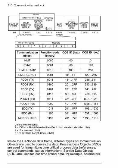
110 Communication protocol
Inside the CANopen data frame, different types of Communication Objects are used to convey the data. Process Data Objects (PDO) are used for transmitting time critical process data (references, control commands, status information); Service Data Objects (SDO) are used for less time critical data, for example, parameters.
START OFFRAME
1 BIT
ARBITRATION FIELD
COMM.
11 BITS
REMOTETRANS-MISSION
REQUEST
1 BIT
CONTROLFIELD
6 BITS
DATAFIELD
0 TO 8
CYCLICREDUNDANCY
CHECK
16 BITS
ACKNOW-LEDGEFIELD
2 BITS
END OFFRAME
7 BITS
FUNCTION CODE NODE ID10 9 8 7 6 5 4 3 2 1 0
Communication object
Function code (binary)
COB ID (hex) COB ID (dec)
NMT 0000 00 0
SYNC 0001 80 128
TIME STAMP 0010 100 256
EMERGENCY 0001 81…FF 129…255
PDO1 (Tx) 0011 181...1FF 385...511
PDO1 (Rx) 0100 201...27F 513...639
PDO6 (Tx) 0101 281...2FF 641...767
PDO6 (Rx) 0110 301...37F 769...895
PDO21 (Tx) 0111 381...3FF 897...1023
PDO21 (Rx) 1000 401...47F 1025...1151
SDO (Tx) 1011 581…5FF 1409…1535
SDO (Rx) 1100 601…67F 1537…1663
NODEGUARD 1110 701…77F 1793…1919
OBJECT ID(COB ID)
BYTES
(CRC)(RTR)
(OR 29 BITS)
1 2 3
Header
Control field contents:1 = IDE bit = 29-bit Extended identifier / 11-bit standard identifier (1 bit)2 = r0 = reserved (1 bit)3 = DLC = Data Length Code (4 bits)

Communication protocol 111
In addition, there are Special Function Objects and Network Management Objects.
FCAN-01 boot-up sequence andNetwork Management (NMT)
The adapter module supports the boot-up sequence of a “Minimum Capability Device”, as defined by the CANopen Communication Profile. The boot-up state diagram of the adapter module is shown below.
The NMT (Network Management) message is mapped to a single CAN frame with data length of 2 bytes. Its identifier is 0. The first byte contains the command specifier and the second byte contains the Node ID of the device, which must perform the command. The NMT message transmitted by the NMT master forces the nodes to transit to another NMT state. The CANopen state machine specifies the following states: Initialization, Pre-Operational, Operational and Stopped. After power-on, each CANopen device
Initialization
Reset application
(13)
(10)
(11)
(14)
Power on
(12)
(6) (8)
(8)(7)
(7)(6)
Reset communication
Init
Pre-operational
Stopped
Operational
(6) Start_Remote_Node indication(7) Stop_Remote_Node indication(8) Enter_Pre-Operational_State indication(10) Reset_Node indication(11) Reset_Communication indication(12) After Initialization is finished(13) (14) After Reset is performed
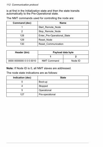
112 Communication protocol
is at first in the Initialization state and then the state transits automatically to the Pre-Operational state.The NMT commands used for controlling the node are:
Note: If Node ID is 0, all NMT slaves are addressed.The node state indications are as follows:
Command (dec) Name1 Start_Remote_Node
2 Stop_Remote_Node
128 Enter_Pre-Operational_State
129 Reset_Node
130 Reset_Communication
Header (bin) Payload data byte1 2
0000 0000000 0 0 0 0010 NMT Command Node ID
Indication (dec) State0 Boot-up
4 Stopped
5 Operational
127 Pre-operational
Communication protocol 113
Process Data Objects (PDO)Process Data Object (PDO) is used for time critical process data exchange. PDO transmissions can be controlled by an internal timer, by remote requests or by the received Sync message. For each PDO the transmission mode of the PDO as well as the default mappings of the application objects are described in the Object Dictionary. The adapter module supports also configuration of the PDOs with drive parameters.The adapter module supports a maximum of three PDOs in both directions. By default only Tx PDO1 and Rx PDO1 are enabled (valid) and Tx/Rx PDO6 and Tx/Rx PDO21 are disabled (not valid).PDO mapping defines which application objects (parameters) are transmitted within a PDO. PDO mappings of the adapter module can be changed in the Pre-operational state (variable objects). Transmission of the enabled (valid) PDOs is possible only in the Operational state.Each PDO can contain up to 8 bytes of process data. In ACS355, the first mapping entries of Tx/Rx PDO1 and Tx/Rx PDO6 are fixed and cannot be changed. The length of the PDOs and mapping entries of the PDOs are configurable.The mapping entries of the PDOs can be configured through CANopen objects or from the drive with fieldbus configuration parameters. The configuration location is selected from the drive with parameter 04 CONF LOC of the fieldbus configuration group A (group 1) (parameter 51.04 in ACS355, ACSM1, ACS850 and ACS880).When mapping through CANopen objects, the PDO length must be set to zero before the mapping entries can be changed.
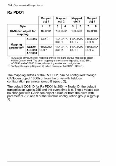
114 Communication protocol
Rx PDO1
The mapping entries of the Rx PDO1 can be configured through CANopen object 1600h or from the drive with fieldbus configuration parameter group B (group 2).The default COB ID for Rx PDO1 is 200h + Node ID, the default transmission type is 255 and the event time is 0. These values can be changed with CANopen object 1400h or from the drive with parameters 7, 8 and 9 of the fieldbus configuration group A (group 1).
Mapped obj 1
Mapped obj 2
Mapped obj 3
Mapped obj 4
Byte 1 2 3 4 5 6 7 8CANopen object for
mapping1600h01 1600h02 1600h03 1600h04
Mapping parameter2)
ACS355 Fixed1) FBA DATA OUT 1
FBA DATA OUT 2
FBA DATA OUT 3
ACSM1ACS850ACS880
FBA DATA OUT 1
FBA DATA OUT 2
FBA DATA OUT 3
FBA DATA OUT 4
1) In ACS355 drives, the first mapping entry is fixed and always mapped to object 6040h Control word. The other mapping entries are configurable. In ACSM1, ACS850 and ACS880 drives, all mapping entries are configurable.
2) Configuration group B (group 2) (when parameter 04 CONF LOC = 1)

Communication protocol 115
Tx PDO1
Note: The mapping entries of the Tx PDO1 can be configured through CANopen object 1A00h or from the drive with fieldbus configuration parameter group C (group 3).The default COB ID for Tx PDO1 is 180h + Node ID, the default transmission type is 255 and the event time is 0. These values can be changed with CANopen object 1600h or from the drive with parameters 10, 11 and 12 of the fieldbus configuration group A (group 1).
Mapped obj 1
Mapped obj 2
Mapped obj 3
Mapped obj 4
Byte 1 2 3 4 5 6 7 8CANopen object for
mapping1A00h01 1A00h02 1A00h03 1A00h04
Mapping parameter2)
ACS355 Fixed1) FBA DATA IN 1
FBA DATA IN 2
FBA DATA IN 3
ACSM1ACS850ACS880
FBA DATA IN 1
FBA DATA IN 2
FBA DATA IN 3
FBA DATA IN 4
1) In ACS355 drives, the first mapping entry is fixed and always mapped to object 6041h Status word. The other mapping entries are configurable. In ACSM1, ACS850 and ACS880 drives, all mapping entries are configurable.
2) Configuration group C (group 3) (when parameter 04 CONF LOC = 1)
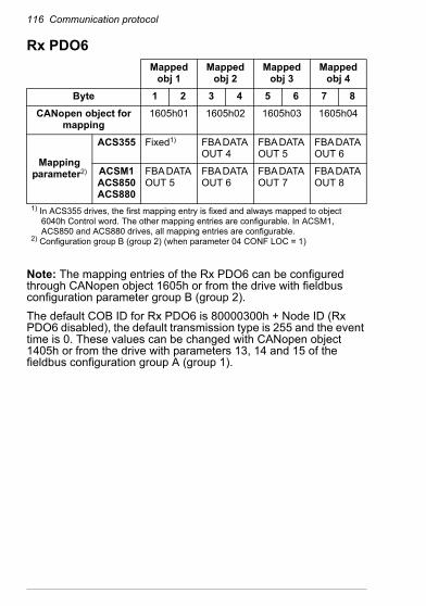
116 Communication protocol
Rx PDO6
Note: The mapping entries of the Rx PDO6 can be configured through CANopen object 1605h or from the drive with fieldbus configuration parameter group B (group 2).The default COB ID for Rx PDO6 is 80000300h + Node ID (Rx PDO6 disabled), the default transmission type is 255 and the event time is 0. These values can be changed with CANopen object 1405h or from the drive with parameters 13, 14 and 15 of the fieldbus configuration group A (group 1).
Mapped obj 1
Mapped obj 2
Mapped obj 3
Mapped obj 4
Byte 1 2 3 4 5 6 7 8CANopen object for
mapping1605h01 1605h02 1605h03 1605h04
Mapping parameter2)
ACS355 Fixed1) FBA DATA OUT 4
FBA DATA OUT 5
FBA DATA OUT 6
ACSM1ACS850ACS880
FBA DATA OUT 5
FBA DATA OUT 6
FBA DATA OUT 7
FBA DATA OUT 8
1) In ACS355 drives, the first mapping entry is fixed and always mapped to object 6040h Control word. The other mapping entries are configurable. In ACSM1, ACS850 and ACS880 drives, all mapping entries are configurable.
2) Configuration group B (group 2) (when parameter 04 CONF LOC = 1)

Communication protocol 117
Tx PDO6
Note: The mapping entries of the Tx PDO6 can be configured through CANopen object 1A05h or from the drive with fieldbus configuration parameter group C (group 3).The default COB ID for Tx PDO6 is 80000280h + Node ID (Tx PDO6 disabled), the default transmission type is 255 and the event time is 0. These values can be changed with CANopen object 1605h or from the drive with parameters 16, 17 and 18 of the fieldbus configuration group A (group 1).
Mapped obj 1
Mapped obj 2
Mapped obj 3
Mapped obj 4
Byte 1 2 3 4 5 6 7 8CANopen object for
mapping1A05h01 1A05h02 1A05h03 1A05h04
Mapping parameter2)
ACS355 Fixed1) FBA DATA IN 4
FBA DATA IN 5
FBA DATA IN 6
ACSM1ACS850ACS880
FBA DATA IN 5
FBA DATA IN 6
FBA DATA IN 7
FBA DATA IN 8
1) In ACS355 drives, the first mapping entry is fixed and it is always mapped to object 6041h Status word. The other mapping entries are configurable. In ACSM1, ACS850 and ACS880 drives, all mapping entries are configurable.
2) Configuration group C (group 3) (when parameter 04 CONF LOC = 1)
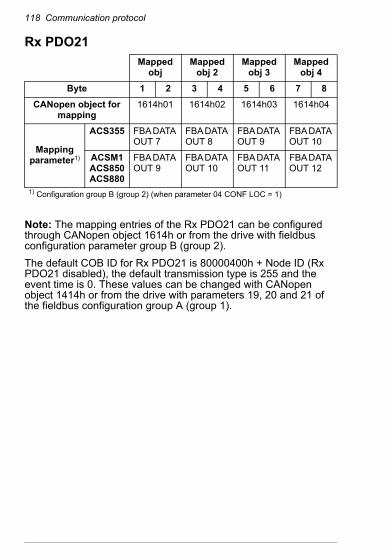
118 Communication protocol
Rx PDO21
Note: The mapping entries of the Rx PDO21 can be configured through CANopen object 1614h or from the drive with fieldbus configuration parameter group B (group 2).The default COB ID for Rx PDO21 is 80000400h + Node ID (Rx PDO21 disabled), the default transmission type is 255 and the event time is 0. These values can be changed with CANopen object 1414h or from the drive with parameters 19, 20 and 21 of the fieldbus configuration group A (group 1).
Mapped obj
Mapped obj 2
Mapped obj 3
Mapped obj 4
Byte 1 2 3 4 5 6 7 8CANopen object for
mapping1614h01 1614h02 1614h03 1614h04
Mapping parameter1)
ACS355 FBA DATA OUT 7
FBA DATA OUT 8
FBA DATA OUT 9
FBA DATA OUT 10
ACSM1ACS850ACS880
FBA DATA OUT 9
FBA DATA OUT 10
FBA DATA OUT 11
FBA DATA OUT 12
1) Configuration group B (group 2) (when parameter 04 CONF LOC = 1)
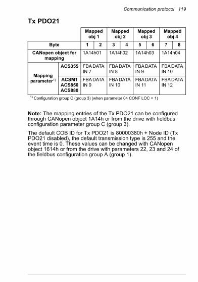
Communication protocol 119
Tx PDO21
Note: The mapping entries of the Tx PDO21 can be configured through CANopen object 1A14h or from the drive with fieldbus configuration parameter group C (group 3).The default COB ID for Tx PDO21 is 80000380h + Node ID (Tx PDO21 disabled), the default transmission type is 255 and the event time is 0. These values can be changed with CANopen object 1614h or from the drive with parameters 22, 23 and 24 of the fieldbus configuration group A (group 1).
Mapped obj 1
Mapped obj 2
Mapped obj 3
Mapped obj 4
Byte 1 2 3 4 5 6 7 8CANopen object for
mapping1A14h01 1A14h02 1A14h03 1A14h04
Mapping parameter1)
ACS355 FBA DATA IN 7
FBA DATA IN 8
FBA DATA IN 9
FBA DATA IN 10
ACSM1ACS850ACS880
FBA DATA IN 9
FBA DATA IN 10
FBA DATA IN 11
FBA DATA IN 12
1) Configuration group C (group 3) (when parameter 04 CONF LOC = 1)
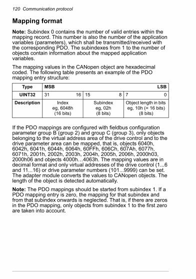
120 Communication protocol
Mapping formatNote: Subindex 0 contains the number of valid entries within the mapping record. This number is also the number of the application variables (parameters), which shall be transmitted/received with the corresponding PDO. The subindexes from 1 to the number of objects contain information about the mapped application variables.The mapping values in the CANopen object are hexadecimal coded. The following table presents an example of the PDO mapping entry structure:
If the PDO mappings are configured with fieldbus configuration parameter group B (group 2) and group C (group 3), only objects belonging to the virtual address area of the drive control and to the drive parameter area can be mapped, that is, objects 6040h, 6042h, 6041h, 6044h, 6064h, 60FFh, 606Ch, 607Ah, 6077h, 6071h, 2001h, 2002h, 2003h, 2004h, 2005h, 2006h, 2000h03, 2000h06 and objects 4000h…4063h. The mapping values are in decimal format and only virtual addresses of the drive control (1...6 and 11...16) or drive parameter numbers (101...9999) can be set. The adapter module converts the values to CANopen objects. The length of the object is detected automatically.Note: The PDO mappings should be started from subindex 1. If a PDO mapping entry is zero, the mapping for that subindex and from that subindex onwards is neglected. That is, if there are zeros in the PDO mapping, only objects from subindex 1 to the first zero are taken into account.
Type MSB LSBUINT32 31 16 15 8 7 0
Description Indexeg, 6048h(16 bits)
Subindexeg, 02h(8 bits)
Object length in bits eg, 10h (= 16 bits)
(8 bits)

Communication protocol 121
PDO configuration via the CAN busThis section gives an example of how to configure PDOs via the CAN bus from the CANopen master. In this example, the following PDO configuration is made:• Rx PDO1 (from master to drive): 6040h Control word and
6042h vl target velocity• Tx PDO1 (from drive to master): 6041h Status word, 6044h vl
control effort and drive parameter 01.20• Tx PDO1 sent to the master at 100 ms intervals
Set the drive parameters as listed in the table below.
Drive parameter1) Setting Description51.02 NODE ID 3 In this example, module node ID = 3
51.03 BIT RATE 0…5 Bit rate used on the CANopen network. See Drive configuration.
51.04 CONF LOC 0 PDO configuration via CAN bus
51.05 PROFILE 0 CiA 4021) The actual parameter group number depends on the drive type. For example, the
fieldbus configuration parameter group A (group 1) equals to parameter group 51 in drives ACS355, ACSM1, ACS850 and ACS880 if the adapter is installed as fieldbus adapter A.
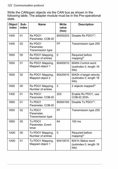
122 Communication protocol
Write the CANopen objects via the CAN bus as shown in the following table. The adapter module must be in the Pre-operational state.
Object index
Sub-index
Name Write value (hex)
Description
1400 01 Rx PDO1 Parameter, COB-ID
80000203 Disable Rx PDO11).
1400 02 Rx PDO1 Parameter, Transmission type
FF Transmission type 255
1600 00 Rx PDO1 Mapping, Number of entries
0 Required before mapping2)
1600 01 Rx PDO1 Mapping, Mapped object 1
60400010 6040h Control word(subindex 0, length 16 bits)
1600 02 Rx PDO1 Mapping, Mapped object 2
60420010 6042h vl target velocity (subindex 0, length 16 bits)
1600 00 Rx PDO1 Mapping, Number of entries
2 2 objects mapped2)
1400 01 Rx PDO1 Parameter, COB-ID
203 Enable Rx PDO1, use COB-ID 203h.
1800 01 Tx PDO1 Parameter, COB-ID
80000183 Disable Tx PDO11).
1800 02 Tx PDO1 Parameter, Transmission type
FF Transmission type 255
1800 05 Tx PDO1 Parameter, Event timer
64 100 ms
1A00 00 Tx PDO1 Mapping, Number of entries
0 Required before mapping2)
1A00 01 Tx PDO1 Mapping, Mapped object 1
60410010 6041h Status word(subindex 0, length 16 bits)
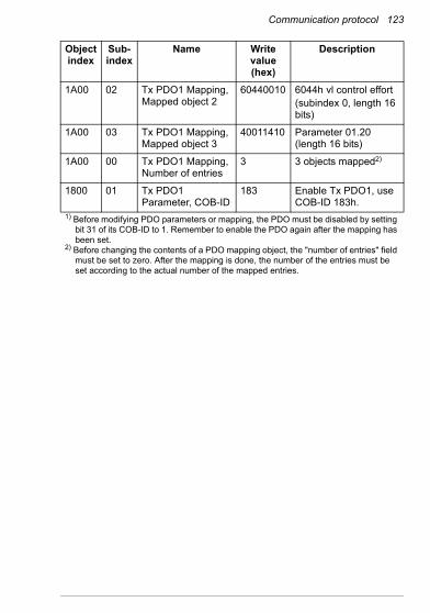
Communication protocol 123
1A00 02 Tx PDO1 Mapping, Mapped object 2
60440010 6044h vl control effort(subindex 0, length 16 bits)
1A00 03 Tx PDO1 Mapping, Mapped object 3
40011410 Parameter 01.20 (length 16 bits)
1A00 00 Tx PDO1 Mapping, Number of entries
3 3 objects mapped2)
1800 01 Tx PDO1 Parameter, COB-ID
183 Enable Tx PDO1, use COB-ID 183h.
1) Before modifying PDO parameters or mapping, the PDO must be disabled by setting bit 31 of its COB-ID to 1. Remember to enable the PDO again after the mapping has been set.
2) Before changing the contents of a PDO mapping object, the "number of entries" field must be set to zero. After the mapping is done, the number of the entries must be set according to the actual number of the mapped entries.
Object index
Sub-index
Name Write value (hex)
Description

124 Communication protocol
Service Data Objects (SDO)Service Data Objects are mainly used for transferring non-time critical data, for example, parameter values. SDOs provide access to the entries in the device Object Dictionary.If 4 bytes (or less) of data is to be transmitted, an Expedited transfer SDO message can be used. Larger quantities of data can be segmented, that is, split between several CAN messages.The following services can be applied to SDO depending on the service requirements:• SDO Upload, which can be divided into
• Initiate SDO Upload• Upload SDO Segment.
• SDO Download, which can be divided into• Initiate SDO Download• Download SDO Segment.
• Abort SDO Transfer
With expedited transfer all data is transferred during the initialization phase (Initiate SDO Upload/Download). With segmented transfer only part of the data is transferred during the initialization phase and the rest of the data is transferred during the Upload/Download SDO Segment phase.The COB IDs for the SDO communication are:• Client to Server (Master to Slave): 600h + Node ID• Server to Client (Slave to Master): 580h + Node ID.
SDO DownloadThrough this service the client of an SDO downloads data to the server (owner of the Object Dictionary).The data, the multiplexor (index and subindex) of the data set that is downloaded and the data size are indicated to the server. The service is confirmed. The remote result parameter will indicate the success or failure of the request. In case of a failure, an Abort SDO Transfer request has to be executed.
Communication protocol 125
SDO UploadThrough this service the client of an SDO requests the server to prepare to upload data to the client.The multiplexor (index and subindex) of the data set to be uploaded is indicated to the server. The service is confirmed. The remote result parameter will indicate the success of the request. In case of a failure, an Abort SDO Transfer request has to be executed. In case of success, the size of the data to be uploaded is confirmed. In case of successful expedited upload, this service concludes the upload of the data set (identified by the multiplexor) and confirms the corresponding data.
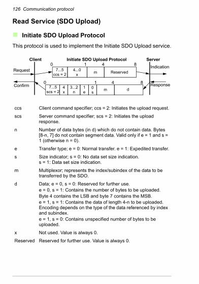
126 Communication protocol
Read Service (SDO Upload)
Initiate SDO Upload ProtocolThis protocol is used to implement the Initiate SDO Upload service.
ccs Client command specifier; ccs = 2: Initiates the upload request.
scs Server command specifier; scs = 2: Initiates the upload response.
n Number of data bytes (in d) which do not contain data. Bytes [8-n, 7] do not contain segment data. Valid only if e = 1 and s = 1 (otherwise n = 0).
e Transfer type; e = 0: Normal transfer. e = 1: Expedited transfer.
s Size indicator; s = 0: No data set size indication.s = 1: Data set size indication.
m Multiplexor; represents the index/subindex of the data to be transferred by the SDO.
d Data; e = 0, s = 0: Reserved for further use.e = 0, s = 1: Contains the number of bytes to be uploaded.Byte 4 contains the LSB and byte 7 contains the MSB.e = 1, s = 1: Contains the data of length 4-n to be uploaded. Encoding depends on the type of the data referenced by index and subindex.e = 1, s = 0: Contains unspecified number of bytes to be uploaded.
x Not used. Value is always 0.
Reserved Reserved for further use. Value is always 0.
Client Initiate SDO Upload Protocol
Request
Confirm
ServerIndication
Response
4...0x
7...5ccs = 2
7...5scs = 2
4x
3...2n
1e
0s
0 1 4 8
0 1 4 8
Reservedm
m d
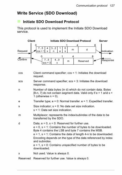
Communication protocol 127
Write Service (SDO Download)
Initiate SDO Download ProtocolThis protocol is used to implement the Initiate SDO Download service.
ccs Client command specifier; ccs = 1: Initiates the download request.
scs Server command specifier; scs = 3: Initiates the download response.
n Number of data bytes (in d) which do not contain data. Bytes [8-n, 7] do not contain segment data. Valid only if e = 1 and s = 1 (otherwise n = 0).
e Transfer type; e = 0: Normal transfer. e = 1: Expedited transfer.
s Size indicator; s = 0: No data set size indication.s = 1: Data set size indication.
m Multiplexor; represents the index/subindex of the data to be transferred by the SDO.
d Data; e = 0, s = 0: Reserved for further use.e = 0, s = 1: Contains the number of bytes to be downloaded. Byte 4 contains the LSB and byte 7 contains the MSB.e = 1, s = 1: Contains the data of length 4-n to be downloaded.Encoding depends on the type of the data referenced by index and subindex.e = 1, s = 0: Contains unspecified number of bytes to be downloaded.
x Not used. Value is always 0.
Reserved Reserved for further use. Value is always 0.
Client Initiate SDO Download Protocol
Request
Confirm
Server
Indication
Response4...0x
7...5scs = 3
7...5ccs = 1
4x
3...2n
1e
0s
0 1 4 8
0 1 4 8
Reserved
m
m
d
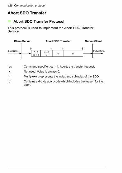
128 Communication protocol
Abort SDO Transfer
Abort SDO Transfer ProtocolThis protocol is used to implement the Abort SDO Transfer Service.
cs Command specifier; cs = 4: Aborts the transfer request.
x Not used. Value is always 0.
m Multiplexor; represents the index and subindex of the SDO.
d Contains a 4-byte abort code which includes the reason for the abort.
Client/Server Abort SDO Transfer
Request
Server/Client
Indication4...0x
7...5cs = 4
0 1 4 8
dm

Communication protocol 129
Abort code description
Error class
Error code
Additional code
Description
05 03 0000h Toggle bit not alternated
04 0000h SDO protocol time-out
0001h Client/Server command specifier not valid or unknown
0002h Invalid block size (block mode only)
0003h Invalid sequence number (block mode only)
0004h CRC error (block mode only)
0005h Out of memory
06 01 0000h Unsupported access to an object
0001h Attempt to read a write-only object.
0002h Attempt to write a read-only object.
02 0000h Object does not exist in the Object Dictionary.
04 0041h Object cannot be mapped to the PDO.
0042h Number and length of the objects to be mapped would exceed the PDO length.
0043h General parameter incompatibility
0047h General internal incompatibility in the device
06 0000h Access failed because of hardware error
07 0010h Data type does not match. The length of the service parameter does not match.
0012h Data type does not match. The length of the service parameter is too long.
0013h Data type does not match. The length of the service parameter is too short.
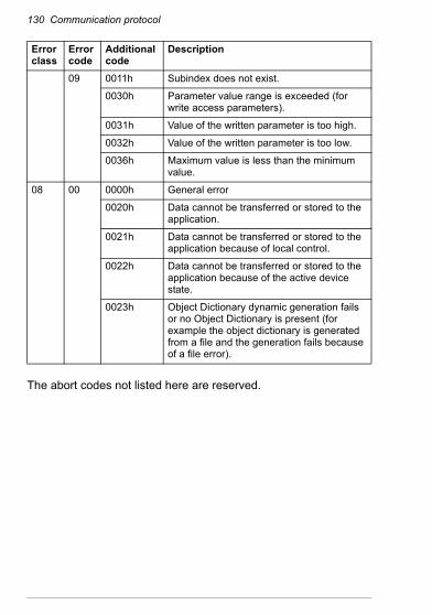
130 Communication protocol
The abort codes not listed here are reserved.
09 0011h Subindex does not exist.
0030h Parameter value range is exceeded (for write access parameters).
0031h Value of the written parameter is too high.
0032h Value of the written parameter is too low.
0036h Maximum value is less than the minimum value.
08 00 0000h General error
0020h Data cannot be transferred or stored to the application.
0021h Data cannot be transferred or stored to the application because of local control.
0022h Data cannot be transferred or stored to the application because of the active device state.
0023h Object Dictionary dynamic generation fails or no Object Dictionary is present (for example the object dictionary is generated from a file and the generation fails because of a file error).
Error class
Error code
Additional code
Description
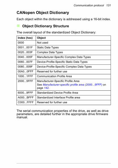
Communication protocol 131
CANopen Object DictionaryEach object within the dictionary is addressed using a 16-bit index.
Object Dictionary StructureThe overall layout of the standardized Object Dictionary:
The serial communication properties of the drive, as well as drive parameters, are detailed further in the appropriate drive firmware manual.
Index (hex) Object0000 Not used
0001...001F Static Data Types
0020...003F Complex Data Types
0040...005F Manufacturer-Specific Complex Data Types
0060...007F Device-Profile-Specific Static Data Types
0080...009F Device-Profile-Specific Complex Data Types
00A0...0FFF Reserved for further use
1000...1FFF Communication Profile Area
2000...5FFF Manufacturer-Specific Profile AreaSee Manufacturer-specific profile area (2000...5FFF) on page 142.
6000...9FFF Standardized Device Profile Area
A000...BFFF Standardized Interface Profile area
C000...FFFF Reserved for further use
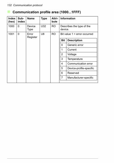
132 Communication protocol
Communication profile area (1000...1FFF)
Index (hex)
Sub-index
Name Type Attri-bute
Information
1000 0 Device Type
U32 RO Describes the type of the device.
1001 0 Error Register
U8 RO Bit value 1 = error occurred
Bit Description0 Generic error
1 Current
2 Voltage
3 Temperature
4 Communication error
5 Device-profile-specific
6 Reserved
7 Manufacturer-specific

Communication protocol 133
1003 0 Pre-defined Error Field
U8 RW Number of errors occurred. Errors are listed in subindexes 1 to 5. The list is deleted by writing a zero.
1 Pre-defined Error Field
U32 RO List of errors. The most recent error is at subindex 1. When a new error occurs, the previous errors move down the list. Error numbers comprise a 16-bit error code (see the appropriate drive firmware manual and Appendix B – CANopen error codes) and a 16-bit additional information field (0 with FCAN-01). The error code is contained in the lower 2 bytes (LSB), the additional information in the upper 2 bytes (MSB).
… … … …
5 Pre-defined Error Field
U32 RO
1005 0 COB ID Sync Message
U32 RW Identifier of the SYNC message. The SYNC message controls the actions of PDOs that have the Synchronous transmission type.
Index (hex)
Sub-index
Name Type Attri-bute
Information
Slave to master
HeaderByte
1…2 3
0001xxxxxx01000 Error code
Error register
4...7 8
Addi-tional error info
Unused
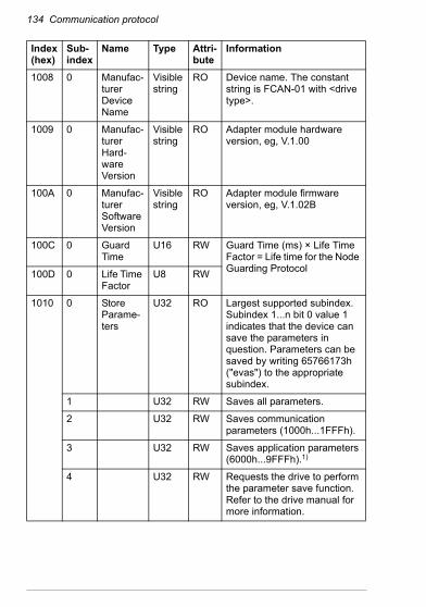
134 Communication protocol
1008 0 Manufac-turer Device Name
Visible string
RO Device name. The constant string is FCAN-01 with <drive type>.
1009 0 Manufac-turer Hard-ware Version
Visible string
RO Adapter module hardware version, eg, V.1.00
100A 0 Manufac-turer Software Version
Visible string
RO Adapter module firmware version, eg, V.1.02B
100C 0 Guard Time
U16 RW Guard Time (ms) × Life Time Factor = Life time for the Node Guarding Protocol100D 0 Life Time
FactorU8 RW
1010 0 Store Parame-ters
U32 RO Largest supported subindex. Subindex 1...n bit 0 value 1 indicates that the device can save the parameters in question. Parameters can be saved by writing 65766173h ("evas") to the appropriate subindex.
1 U32 RW Saves all parameters.
2 U32 RW Saves communication parameters (1000h...1FFFh).
3 U32 RW Saves application parameters (6000h...9FFFh).1)
4 U32 RW Requests the drive to perform the parameter save function. Refer to the drive manual for more information.
Index (hex)
Sub-index
Name Type Attri-bute
Information
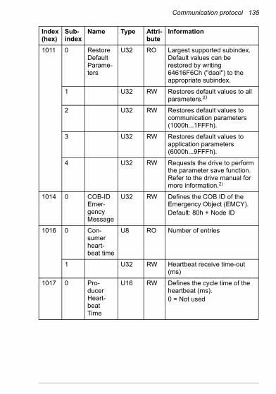
Communication protocol 135
1011 0 Restore Default Parame-ters
U32 RO Largest supported subindex. Default values can be restored by writing 64616F6Ch ("daol") to the appropriate subindex.
1 U32 RW Restores default values to all parameters.2)
2 U32 RW Restores default values to communication parameters (1000h...1FFFh).
3 U32 RW Restores default values to application parameters (6000h...9FFFh).
4 U32 RW Requests the drive to perform the parameter save function. Refer to the drive manual for more information.2)
1014 0 COB-ID Emer-gency Message
U32 RW Defines the COB ID of the Emergency Object (EMCY).Default: 80h + Node ID
1016 0 Con-sumer heart-beat time
U8 RO Number of entries
1 U32 RW Heartbeat receive time-out (ms)
1017 0 Pro-ducer Heart-beat Time
U16 RW Defines the cycle time of the heartbeat (ms).0 = Not used
Index (hex)
Sub-index
Name Type Attri-bute
Information
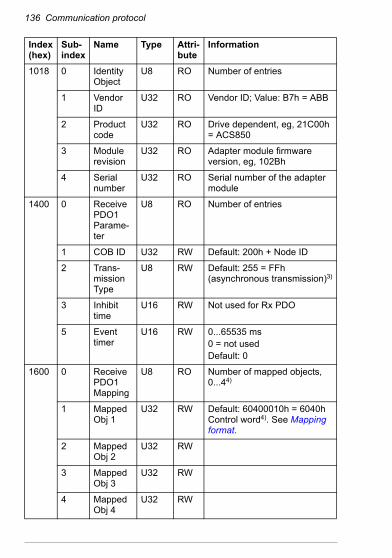
136 Communication protocol
1018 0 Identity Object
U8 RO Number of entries
1 Vendor ID
U32 RO Vendor ID; Value: B7h = ABB
2 Product code
U32 RO Drive dependent, eg, 21C00h = ACS850
3 Module revision
U32 RO Adapter module firmware version, eg, 102Bh
4 Serial number
U32 RO Serial number of the adapter module
1400 0 Receive PDO1 Parame-ter
U8 RO Number of entries
1 COB ID U32 RW Default: 200h + Node ID
2 Trans-mission Type
U8 RW Default: 255 = FFh (asynchronous transmission)3)
3 Inhibit time
U16 RW Not used for Rx PDO
5 Event timer
U16 RW 0...65535 ms0 = not usedDefault: 0
1600 0 Receive PDO1 Mapping
U8 RO Number of mapped objects, 0...44)
1 Mapped Obj 1
U32 RW Default: 60400010h = 6040h Control word4). See Mapping format.
2 Mapped Obj 2
U32 RW
3 Mapped Obj 3
U32 RW
4 Mapped Obj 4
U32 RW
Index (hex)
Sub-index
Name Type Attri-bute
Information

Communication protocol 137
1405 0 Receive PDO6 Parame-ter
U8 RO Number of entries
1 COB ID U32 RW Default: 80000300h + Node ID (= PDO not valid)3)
2 Trans-mission Type
U8 RW Default: 255 asynchronous3)
3 Inhibit time
U16 RW Not used for Rx PDO
5 Event timer
U16 RW 0...65535 ms0 = not usedDefault: 0
1605 0 Receive PDO6 Mapping
U8 RO Number of mapped objects, 0...44)
1 Mapped Obj 1
U32 RW Default: 60400010h = 6040h Control word4). See Mapping format.
2 Mapped Obj 2
U32 RW
3 Mapped Obj 3
U32 RW
4 Mapped Obj 4
U32 RW
Index (hex)
Sub-index
Name Type Attri-bute
Information
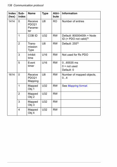
138 Communication protocol
1414 0 Receive PDO21 Parame-ter
U8 RO Number of entries
1 COB ID U32 RW Default: 80000400h + Node ID (= PDO not valid)3)
2 Trans-mission Type
U8 RW Default: 2553)
3 Inhibit time
U16 RW Not used for Rx PDO
5 Event timer
U16 RW 0...65535 ms0 = not usedDefault: 0
1614 0 Receive PDO21 Mapping
U8 RW Number of mapped objects, 0...4
1 Mapped Obj 1
U32 RW See Mapping format.
2 Mapped Obj 2
U32 RW
3 Mapped Obj 3
U32 RW
4 Mapped Obj 4
U32 RW
Index (hex)
Sub-index
Name Type Attri-bute
Information

Communication protocol 139
1800 0 Transmit PDO1 Parame-ter
U8 RO Number of entries
1 COB ID U32 RW Default: 180h + Node ID
2 Trans-mission Type
U8 RW Default: 255 (asynchronous transmission)3)
3 Inhibit Time
U16 RW Minimum interval for PDO transmission (= value x 100 microseconds)
5 Event Timer
U16 RW 0...65535 ms0 = Not usedDefault: 0
1A00 0 Transmit PDO1 Mapping
U32 RO Number of mapped objects, 0...44)
1 Mapped Obj 1
U32 RW Default: 60410010h = 6041h Status word4). See Mapping format.
2 Mapped Obj 2
U32 RW
3 Mapped Obj 3
U32 RW
4 Mapped Obj 4
U32 RW
Index (hex)
Sub-index
Name Type Attri-bute
Information
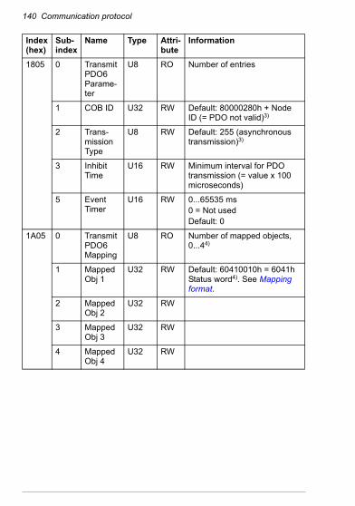
140 Communication protocol
1805 0 Transmit PDO6 Parame-ter
U8 RO Number of entries
1 COB ID U32 RW Default: 80000280h + Node ID (= PDO not valid)3)
2 Trans-mission Type
U8 RW Default: 255 (asynchronous transmission)3)
3 Inhibit Time
U16 RW Minimum interval for PDO transmission (= value x 100 microseconds)
5 Event Timer
U16 RW 0...65535 ms0 = Not usedDefault: 0
1A05 0 Transmit PDO6 Mapping
U8 RO Number of mapped objects, 0...44)
1 Mapped Obj 1
U32 RW Default: 60410010h = 6041h Status word4). See Mapping format.
2 Mapped Obj 2
U32 RW
3 Mapped Obj 3
U32 RW
4 Mapped Obj 4
U32 RW
Index (hex)
Sub-index
Name Type Attri-bute
Information
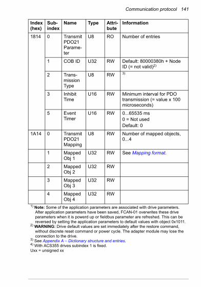
Communication protocol 141
1814 0 Transmit PDO21 Parame-ter
U8 RO Number of entries
1 COB ID U32 RW Default: 80000380h + Node ID (= not valid)2)
2 Trans-mission Type
U8 RW 3)
3 Inhibit Time
U16 RW Minimum interval for PDO transmission (= value x 100 microseconds)
5 Event Timer
U16 RW 0...65535 ms0 = Not usedDefault: 0
1A14 0 Transmit PDO21 Mapping
U8 RW Number of mapped objects, 0...4
1 Mapped Obj 1
U32 RW See Mapping format.
2 Mapped Obj 2
U32 RW
3 Mapped Obj 3
U32 RW
4 Mapped Obj 4
U32 RW
1) Note: Some of the application parameters are associated with drive parameters. After application parameters have been saved, FCAN-01 overwrites these drive parameters when it is powerd up or fieldbus parameter are refreshed. This can be reversed by setting the application parameters to default values with object 0x1011.
2) WARNING: Drive default values are set immediately after the restore command, without discrete reset command or power cycle. The adapter module may lose the connection to the drive.
3) See Appendix A – Dictionary structure and entries.4) With ACS355 drives subindex 1 is fixed.Uxx = unsigned xx
Index (hex)
Sub-index
Name Type Attri-bute
Information
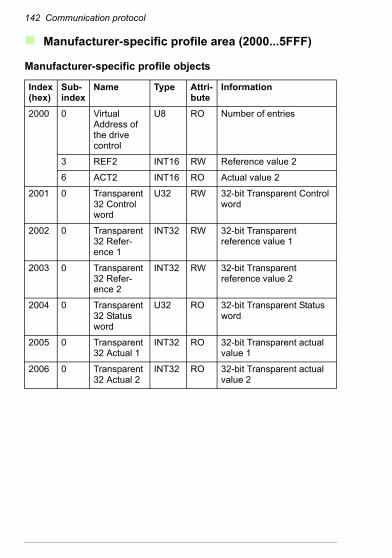
142 Communication protocol
Manufacturer-specific profile area (2000...5FFF)
Manufacturer-specific profile objects
Index (hex)
Sub-index
Name Type Attri-bute
Information
2000 0 Virtual Address of the drive control
U8 RO Number of entries
3 REF2 INT16 RW Reference value 2
6 ACT2 INT16 RO Actual value 2
2001 0 Transparent 32 Control word
U32 RW 32-bit Transparent Control word
2002 0 Transparent 32 Refer-ence 1
INT32 RW 32-bit Transparent reference value 1
2003 0 Transparent 32 Refer-ence 2
INT32 RW 32-bit Transparent reference value 2
2004 0 Transparent 32 Status word
U32 RO 32-bit Transparent Status word
2005 0 Transparent 32 Actual 1
INT32 RO 32-bit Transparent actual value 1
2006 0 Transparent 32 Actual 2
INT32 RO 32-bit Transparent actual value 2
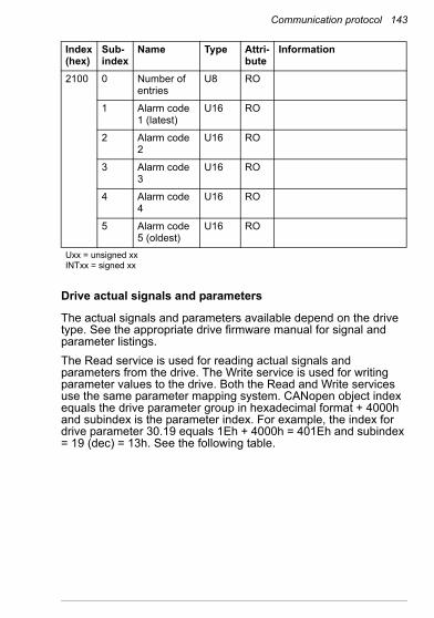
Communication protocol 143
Drive actual signals and parameters
The actual signals and parameters available depend on the drive type. See the appropriate drive firmware manual for signal and parameter listings.The Read service is used for reading actual signals and parameters from the drive. The Write service is used for writing parameter values to the drive. Both the Read and Write services use the same parameter mapping system. CANopen object index equals the drive parameter group in hexadecimal format + 4000h and subindex is the parameter index. For example, the index for drive parameter 30.19 equals 1Eh + 4000h = 401Eh and subindex = 19 (dec) = 13h. See the following table.
2100 0 Number of entries
U8 RO
1 Alarm code 1 (latest)
U16 RO
2 Alarm code 2
U16 RO
3 Alarm code 3
U16 RO
4 Alarm code 4
U16 RO
5 Alarm code 5 (oldest)
U16 RO
Uxx = unsigned xxINTxx = signed xx
Index (hex)
Sub-index
Name Type Attri-bute
Information

144 Communication protocol
Index (hex)
Sub-index
Name Type Attribute Information
4001 1 Drive signal 1.01 1) 2) 3)
2 Drive signal 1.02 1) 2) 3)
• • • • • • • • • • • • • • • • • •
4002 1 Drive signal 2.01 1) 2) 3)
• • • • • • • • • • • • • • • • • •
4003 1 Drive signal 3.01 1) 2) 3)
• • • • • • • • • • • • • • • • • •
400A 1 Drive par. 10.01 1) 2) 3)
2 Drive par. 10.02 1) 2) 3)
• • • • • • • • • • • • • • • • • •
400B 1 Drive par. 11.01 1) 2) 3)
• • • • • • • • • • • • • • • • • •
4063 1 Drive par. 99.01 1) 2) 3)
• • • • • • • • • • • • • • • • • •Subindex 0 = number of mapped objects.1) U16, INT16, U32 or INT322) Depends on the parameter type of the drive.3) See the appropriate drive firmware manual.

Communication protocol 145
Standardized device profile area (6000...9FFF)Index(hex)
Sub Access Type Name Information Sup-port
603F RO U16 Error code
See Appendix B – CANopen error codes.
all
6040 RW U16 Control word
See Communication protocol. all
6041 RO U16 Status word
all
6042 RW INT16 Target velocity
vl
6043 RO INT16 Vl velocity demand
Instantaneous velocity provided by the ramp function. Scaled to the unit of the vl target velocity.
vl
6044 RO INT16 Vl control effort
Actual velocity vl
6046 Vl velocity min max amount
Vl velocity min max amount vl
0 RO U8 Number of entries
vl
1 RW U32 Vl velocity min amount
Mapped internally to vl velocity min pos and vl velocity max neg values
vl
2 RW U32 Vl velocity max amount
Mapped internally to vl velocity max pos and vl velocity max neg values
vl
6048 Vl velocity accelera-tion
Slope of the acceleration ramp = delta speed / delta time. If delta time = 0, the function follows the set point (=target velocity) value.
vl
0 RO U8 Number of entries
vl
1 RW U32 Delta speed
[rpm] vl
2 RW U16 Delta time 0...65535 [sec] vl
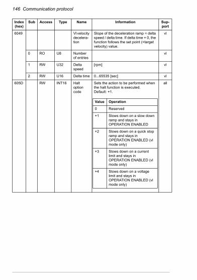
146 Communication protocol
6049 Vl velocity decelera-tion
Slope of the deceleration ramp = delta speed / delta time. If delta time = 0, the function follows the set point (=target velocity) value.
vl
0 RO U8 Number of entries
vl
1 RW U32 Delta speed
[rpm] vl
2 RW U16 Delta time 0...65535 [sec] vl
605D RW INT16 Halt option code
Sets the action to be performed when the halt function is executed.Default: +1.
all
Index(hex)
Sub Access Type Name Information Sup-port
Value Operation
0 Reserved
+1 Slows down on a slow down ramp and stays in OPERATION ENABLED
+2 Slows down on a quick stop ramp and stays in OPERATION ENABLED (vl mode only)
+3 Slows down on a current limit and stays in OPERATION ENABLED (vl mode only)
+4 Slows down on a voltage limit and stays in OPERATION ENABLED (vl mode only)
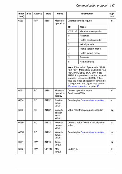
Communication protocol 147
6060 RW INT8 Modes of operation
Operation mode request
Note: If the value of parameter 50.04 FBA REF1 MODESEL and 50.05 FBA REF2 MODESEL of ACSM1 is (5) AUTO, it is possible to set the mode of operation with object 6060h. Other-wise the mode of operation cannot be changed with this object. See section Modes of operation on page 90.
all
6061 RO INT8 Modes of operation display
Current operation modeSee index 6060h.
all
6064 RO INT32 Position actual value
See chapter Communication profiles. pp
6069 RO INT32 Velocity sensor actual value
Value read from a velocity encoder pv
606B RO INT32 Velocity demand value
Demand value from the velocity con-troller
pv
606C RO INT32 Velocity actual value
See chapter Communication profiles. pv
6071 RW INT16 Target torque
tq
6072 RW UINT16 Max torque
Unit 0.1% all
Index(hex)
Sub Access Type Name Information Sup-port
Bit Mode
-128…-1 Manufacturer-specific
0 Reserved
1 Profile position mode
2 Velocity mode
3 Profile velocity mode
4 Profile torque mode
5 Reserved
6 Homing mode

148 Communication protocol
6073 RW UINT16 Max cur-rent
Unit 0.1%
Supported with ACS850 and ACQ810.
all
6077 RW INT16 Torque actual value
See chapter Communication profiles. tq
607A RW INT32 Target position
pp
6081 RW INT32 Profile velocity
Velocity attained at the end of the acceleration ramp during a profiled move
pp, tq
6083 RW U32 Profile accelera-tion
Acceleration during a profiled move pp, tq
6084 RW U32 Profile decelera-tion
Deceleration during a profiled move pp, tq
6098 RW INT8 Homing method
0 = No homing method selected1...35 = Methods 1...35See the firmware manual of the drive for description of the available homing methods.
hm
6099 Homing speeds
hm
0 RO U8 Number of entries
hm
1 RO U32 Speed during search for switch
hm
2 RO U32 Speed during search for zero
hm
60FF RW INT32 Target velocity
See chapter Communication profiles. pv
Index(hex)
Sub Access Type Name Information Sup-port
ValueNominal current
Current 1000

Communication protocol 149
6402 RW U16 Motor type
all
6502 RO U32 Sup-ported drive modes
all
Index(hex)
Sub Access Type Name Information Sup-port
Value(hex)
Type
0000 Non-standard motor
0001 Phase-modulated DC motor
0002 Frequency-controlled DC motor
0003 PM synchronous motor
0004 FC synchronous motor
0005 Switched reluctance motor
0006 Wound rotor induction motor
0007 Squirrel cage induction motor
0008 Stepper motor
0009 Micro-step stepper motor
000A Sinusoidal PM BL motor
000B Trapezoidal PM BL motor
000C Reserved
7FFF Reserved
8000 Manufacturer-specific
FFFF Manufacturer-specific
Bit Mode
0 Profile position mode
1 Velocity mode
2 Profile velocity mode
3 Profile torque mode
4 Reserved
5 Homing mode
6 Interpolated position mode
7…15 Reserved
16…31 Manufacturer-specific

150 Communication protocol
6504 RO Visible string
Drive manufac-turer
ABB Drives
6505 RO Visible string
http drive catalog address
www.abb.com/drives
Index(hex)
Sub Access Type Name Information Sup-port

Diagnostics 151
9Diagnostics
What this chapter containsThis chapter explains how to trace faults with the status LEDs on the adapter module.
LED indicationsThe adapter module is equipped with three diagnostic LEDs. The LEDs are described below.
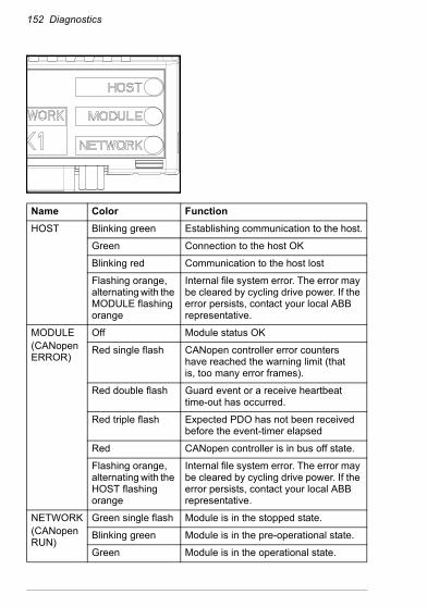
152 Diagnostics
Name Color FunctionHOST Blinking green Establishing communication to the host.
Green Connection to the host OK
Blinking red Communication to the host lost
Flashing orange, alternating with the MODULE flashing orange
Internal file system error. The error may be cleared by cycling drive power. If the error persists, contact your local ABB representative.
MODULE(CANopen ERROR)
Off Module status OK
Red single flash CANopen controller error counters have reached the warning limit (that is, too many error frames).
Red double flash Guard event or a receive heartbeat time-out has occurred.
Red triple flash Expected PDO has not been received before the event-timer elapsed
Red CANopen controller is in bus off state.
Flashing orange, alternating with the HOST flashing orange
Internal file system error. The error may be cleared by cycling drive power. If the error persists, contact your local ABB representative.
NETWORK(CANopen RUN)
Green single flash Module is in the stopped state.
Blinking green Module is in the pre-operational state.
Green Module is in the operational state.
Technical data 153
10Technical data
What this chapter containsThis chapter contains the technical data of the adapter module and the CANopen link.

154 Technical data
FCAN-01The following figure describes the enclosure of the adapter module from the front and side.
Mounting Into the option slot on the drive
Degree of protection IP20
Ambient conditions Applicable ambient conditions specified for the drive in its manuals are in effect.
Indicators Three bicolor LEDs: HOST, MODULE, NETWORK
Connectors 20-pin connector to drive (X2)9-pin male D-SUB connector to bus (X1)
Power supply +3.3 V ±5% max. 300 mA (supplied by the drive)
General Estimated minimum lifetime: 100 000 hAll materials UL/CSA-approvedComplies with EMC standard EN 61800-3:2004.Bus interface functionally isolated from the drivePrinted circuit board conformal coated
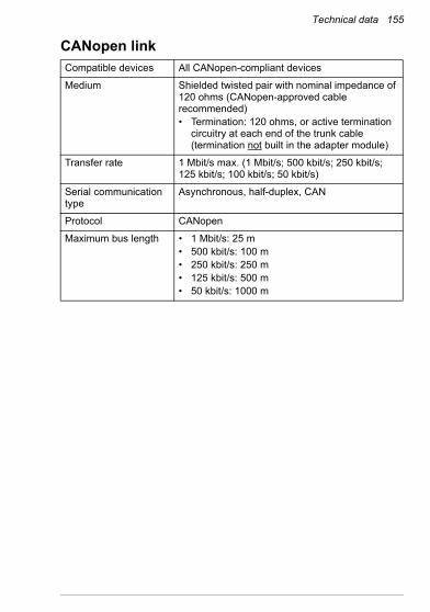
Technical data 155
CANopen linkCompatible devices All CANopen-compliant devices
Medium Shielded twisted pair with nominal impedance of 120 ohms (CANopen-approved cable recommended)• Termination: 120 ohms, or active termination
circuitry at each end of the trunk cable (termination not built in the adapter module)
Transfer rate 1 Mbit/s max. (1 Mbit/s; 500 kbit/s; 250 kbit/s; 125 kbit/s; 100 kbit/s; 50 kbit/s)
Serial communication type
Asynchronous, half-duplex, CAN
Protocol CANopen
Maximum bus length • 1 Mbit/s: 25 m• 500 kbit/s: 100 m• 250 kbit/s: 250 m• 125 kbit/s: 500 m• 50 kbit/s: 1000 m

156 Technical data
Appendix A – Dictionary structure and entries 157
11Appendix A – Dictionary structure and entries
What this chapter containsThis chapter contains information about PDO transmission and mapping.

158 Appendix A – Dictionary structure and entries
Description of transmission type
Description of PDO COB-ID entry
Trans-mission
type
PDO transmissionCyclic Acyclic Synchro-
nousAsyn-chronous
RTR only
0 X X
1...240 X X
241...251 Reserved
252 X X
253 X X
2541) X
2552) X1) The transmission of this PDO is initiated by an event device. The event is
manufacturer-specific.2) The transmission of this PDO is initiated by an event on the device. This event must
be defined in the device profile.
Bit Value Description31 0 PDO valid
1 PDO not valid
30 0 RTR allowed on this PDO
1 No RTR allowed on this PDO
29 0 11-bit ID is used (CAN 2.0A).1)
1 29-bit ID is used (CAN 2.0B).2)
28...11 0 If 11-bit ID is used, bits 28...11 = 0.
x 29-bit COB-ID not supported.
10…0 x COB-ID1) Recommended2) Not supported
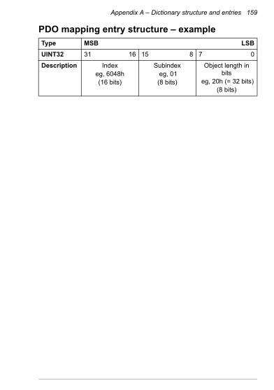
Appendix A – Dictionary structure and entries 159
PDO mapping entry structure – exampleType MSB LSBUINT32 31 16 15 8 7 0
Description Index eg, 6048h (16 bits)
Subindex eg, 01(8 bits)
Object length in bits
eg, 20h (= 32 bits)(8 bits)

160 Appendix A – Dictionary structure and entries

Appendix B – CANopen error codes 161
12Appendix B – CANopen error codes
What this chapter containsThis chapter contains the CANopen error codes.
Error codesError codes can be read from objects 1003h and 603Fh. Error codes between xx80h...xxFFh and between FF00h...FFFFh are manufacturer-specific. Description for these error codes can be found from the appropriate drive firmware manual.
Error code (hex)
Meaning
0000 No error
1000 Generic error
2000 Current
2100 Current on device input side
2110 Short circuit / Earth leakage
2120 Earth leakage
2121 Earth leakage phase L1
2122 Earth leakage phase L2

162 Appendix B – CANopen error codes
2123 Earth leakage phase L3
2130 Short circuit
2131 Short circuit phases L1-L2
2132 Short circuit phases L2-L3
2133 Short circuit phases L3-L1
2200 Internal current
2211 Internal current No. 1
2212 Internal current No. 2
2213 Overcurrent in ramp function
2214 Overcurrent in sequence
2220 Continuous overcurrent
2221 Continuous overcurrent No. 1
2222 Continuous overcurrent No. 2
2230 Short circuit / Earth leakage
2240 Earth leakage
2250 Short circuit
2300 Current on device output side
2310 Continuous overcurrent
2311 Continuous overcurrent No. 1
2312 Continuous overcurrent No. 2
2320 Short circuit / Earth leakage
2330 Earth leakage
2331 Earth leakage phase U
2332 Earth leakage phase V
2333 Earth leakage phase W
2340 Short circuit
2341 Short circuit phases U-V
Error code (hex)
Meaning
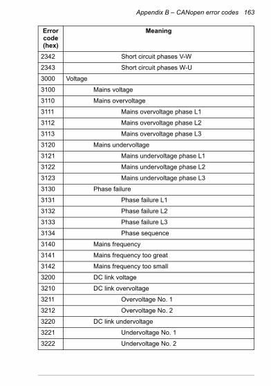
Appendix B – CANopen error codes 163
2342 Short circuit phases V-W
2343 Short circuit phases W-U
3000 Voltage
3100 Mains voltage
3110 Mains overvoltage
3111 Mains overvoltage phase L1
3112 Mains overvoltage phase L2
3113 Mains overvoltage phase L3
3120 Mains undervoltage
3121 Mains undervoltage phase L1
3122 Mains undervoltage phase L2
3123 Mains undervoltage phase L3
3130 Phase failure
3131 Phase failure L1
3132 Phase failure L2
3133 Phase failure L3
3134 Phase sequence
3140 Mains frequency
3141 Mains frequency too great
3142 Mains frequency too small
3200 DC link voltage
3210 DC link overvoltage
3211 Overvoltage No. 1
3212 Overvoltage No. 2
3220 DC link undervoltage
3221 Undervoltage No. 1
3222 Undervoltage No. 2
Error code (hex)
Meaning

164 Appendix B – CANopen error codes
3230 Load error
3300 Output voltage
3310 Output overvoltage
3311 Output overvoltage phase U
3312 Output overvoltage phase V
3313 Output overvoltage phase W
3320 Armature circuit
3321 Armature circuit interrupted
3330 Field circuit
3331 Field circuit interrupted
4000 Temperature
4100 Ambient temperature
4110 Excess ambient temperature
4120 Too low ambient temperature
4130 Temperature supply air
4140 Temperature air outlet
4200 Temperature device
4210 Excess temperature device
4220 Too low temperature device
4300 Temperature drive
4310 Excess temperature drive
4320 Too low temperature drive
4400 Temperature supply
4410 Excess temperature supply
4420 Too low temperature supply
5000 Device hardware
5100 Supply
Error code (hex)
Meaning
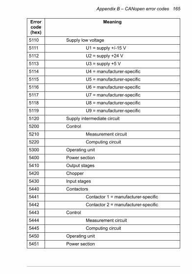
Appendix B – CANopen error codes 165
5110 Supply low voltage
5111 U1 = supply +/-15 V
5112 U2 = supply +24 V
5113 U3 = supply +5 V
5114 U4 = manufacturer-specific
5115 U5 = manufacturer-specific
5116 U6 = manufacturer-specific
5117 U7 = manufacturer-specific
5118 U8 = manufacturer-specific
5119 U9 = manufacturer-specific
5120 Supply intermediate circuit
5200 Control
5210 Measurement circuit
5220 Computing circuit
5300 Operating unit
5400 Power section
5410 Output stages
5420 Chopper
5430 Input stages
5440 Contactors
5441 Contactor 1 = manufacturer-specific
5442 Contactor 2 = manufacturer-specific
5443 Control
5444 Measurement circuit
5445 Computing circuit
5450 Operating unit
5451 Power section
Error code (hex)
Meaning
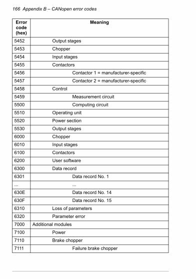
166 Appendix B – CANopen error codes
5452 Output stages
5453 Chopper
5454 Input stages
5455 Contactors
5456 Contactor 1 = manufacturer-specific
5457 Contactor 2 = manufacturer-specific
5458 Control
5459 Measurement circuit
5500 Computing circuit
5510 Operating unit
5520 Power section
5530 Output stages
6000 Chopper
6010 Input stages
6100 Contactors
6200 User software
6300 Data record
6301 Data record No. 1
... ...
630E Data record No. 14
630F Data record No. 15
6310 Loss of parameters
6320 Parameter error
7000 Additional modules
7100 Power
7110 Brake chopper
7111 Failure brake chopper
Error code (hex)
Meaning
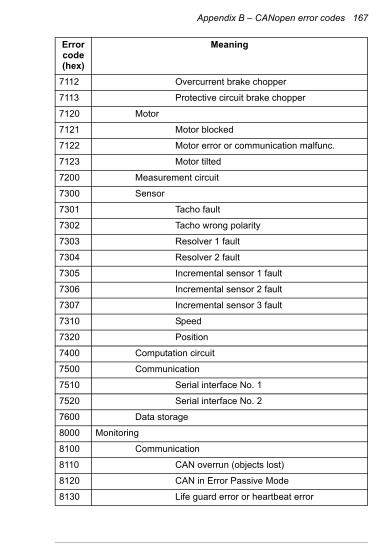
Appendix B – CANopen error codes 167
7112 Overcurrent brake chopper
7113 Protective circuit brake chopper
7120 Motor
7121 Motor blocked
7122 Motor error or communication malfunc.
7123 Motor tilted
7200 Measurement circuit
7300 Sensor
7301 Tacho fault
7302 Tacho wrong polarity
7303 Resolver 1 fault
7304 Resolver 2 fault
7305 Incremental sensor 1 fault
7306 Incremental sensor 2 fault
7307 Incremental sensor 3 fault
7310 Speed
7320 Position
7400 Computation circuit
7500 Communication
7510 Serial interface No. 1
7520 Serial interface No. 2
7600 Data storage
8000 Monitoring
8100 Communication
8110 CAN overrun (objects lost)
8120 CAN in Error Passive Mode
8130 Life guard error or heartbeat error
Error code (hex)
Meaning
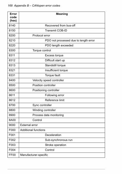
168 Appendix B – CANopen error codes
8140 Recovered from bus-off
8150 Transmit COB-ID
8200 Protocol error
8210 PDO not processed due to length error
8220 PDO length exceeded
8300 Torque control
8311 Excess torque
8312 Difficult start up
8313 Standstill torque
8321 Insufficient torque
8331 Torque fault
8400 Velocity speed controller
8500 Position controller
8600 Positioning controller
8611 Following error
8612 Reference limit
8700 Sync controller
8800 Winding controller
8900 Process data monitoring
8A00 Control
9000 External error
F000 Additional functions
F001 Deceleration
F002 Sub-synchronous run
F003 Stroke operation
F004 Control
FF00 Manufacturer-specific
Error code (hex)
Meaning

Appendix B – CANopen error codes 169
... ...
FFFF Manufacturer-specific
Error code (hex)
Meaning

170 Appendix B – CANopen error codes

Further information
Product and service inquiriesAddress any inquiries about the product to your local ABB representative, quoting the type designation and serial number of the unit in question. A listing of ABB sales, support and service contacts can be found by navigating to www.abb.com/drives and selecting Sales, Support and Service network.
Product trainingFor information on ABB product training, navigate to www.abb.com/drives and select Training courses.
Providing feedback on ABB Drives manualsYour comments on our manuals are welcome. Go to www.abb.com/drives and select Document Library – Manuals feedback form (LV AC drives).
Document library on the InternetYou can find manuals and other product documents in PDF format on the Internet. Go to www.abb.com/drives and select Document Library. You can browse the library or enter selection criteria, for example a document code, in the search field.

3AFE
xxxx
xxxx
Rev
x /
EN
EFF
EC
TIV
E: x
x.xx
.xxx
x
ABB OyAC DrivesP.O. Box 184FI-00381 HELSINKIFINLANDTelephone +358 10 22 11Fax +358 10 22 22681Internethttp://www.abb.com
ABB Inc.Automation Technologies Drives & Motors16250 West Glendale DriveNew Berlin, WI 53151 USATelephone 262 785-3200
800-HELP-365Fax 262 780-5135
ABB Beijing Drive Systems Co. Ltd.No. 1, Block D, A-10 Jiuxianqiao BeiluChaoyang DistrictBeijing, P.R. China, 100015Telephone+86 10 5821 7788Fax +86 10 5821 7618Internethttp://www.abb.com
Contact us
ABB OyDrivesP.O. Box 184FI-00381 HELSINKIFINLANDTelephone +358 10 22 11Fax +358 10 22 22681www.abb.com/drives
ABB Inc.Automation TechnologiesDrives & Motors16250 West Glendale DriveNew Berlin, WI 53151USATelephone 262 785-3200
1-800-HELP-365Fax 262 780-5135www.abb.com/drives
ABB Beijing Drive Systems Co. Ltd.No. 1, Block D,A-10 Jiuxianqiao BeiluChaoyang DistrictBeijing, P.R. China, 100015Telephone +86 10 5821 7788Fax +86 10 5821 7618www.abb.com/drives
3AFE
6861
5500
Rev
E (E
N) 2
012-
04-0
2