EN ELECTRIC RANGE SP ESTUFA ELÉCTRICA...
12
EN ELECTRIC RANGE SP ESTUFA ELÉCTRICA INSTALLATION INSTRUCTIONS INSTRUCCIONES DE INSTALACION .................................................................. .................................................................. 316454921 Rev A January 2012
Transcript of EN ELECTRIC RANGE SP ESTUFA ELÉCTRICA...

EN ELECTRIC RANGESP ESTUFA ELÉCTRICA
INSTALLATION INSTRUCTIONSINSTRUCCIONES DE INSTALACION
.................................................................. ..................................................................
316454921 Rev A January 2012

INSTALLATION AND SERVICE MUST BE PERFORMED BY A QUALIFIED INSTALLER.IMPORTANT: SAVE FOR LOCAL ELECTRICAL INSPECTOR'S USE.
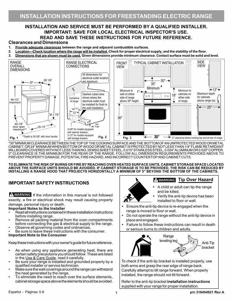
READ AND SAVE THESE INSTRUCTIONS FOR FUTURE REFERENCE.Clearances and Dimensions1. Provide adequate clearances between the range and adjacent combustible surfaces.2. Location—Check location where the range will be installed. Check for proper electrical supply, and the stability of the floor.3. Dimensions that are shown must be used. Given dimensions provide minimum clearance. Contact surface must be solid and level.
*30" MINIMUM CLEARANCE BETWEEN THE TOP OF THE COOKING SURFACE AND THE BOTTOM OF AN UNPROTECTED WOOD OR METALCABINET; OR 24" MINIMUM WHEN BOTTOM OF WOOD OR METAL CABINET IS PROTECTED BY NOT LESS THAN 1/4" FLAME RETARDANTMILLBOARD COVERED WITH NOT LESS THAN NO. 28 MSG SHEET STEEL, 0.015" STAINLESS STEEL, 0.024" ALUMINUM OR 0.020" COPPER.0" CLEARANCE IS THE MINIMUM FOR THE REAR OF THE RANGE. FOLLOW ALL DIMENSION REQUIREMENTS PROVIDED ABOVE TOPREVENT PROPERTY DAMAGE, POTENTIAL FIRE HAZARD, AND INCORRECT COUNTERTOP AND CABINET CUTS.
TO ELIMINATE THE RISK OF BURNS OR FIRE BY REACHING OVER HEATED SURFACE UNITS, CABINET STORAGE SPACE LOCATEDABOVE THE SURFACE UNITS SHOULD BE AVOIDED. IF CABINET STORAGE IS TO BE PROVIDED, THE RISK CAN BE REDUCED BYINSTALLING A RANGE HOOD THAT PROJECTS HORIZONTALLY A MINIMUM OF 5" BEYOND THE BOTTOM OF THE CABINETS.
p/n 316454921 Rev A
If the information in this manual is not followedexactly, a fire or electrical shock may result causing propertydamage, personal injury or death.Important Notes to the Installer• Read all instructions contained in these installation instructions
before installing range.• Remove all packing material from the oven compartments
before connecting the gas & electrical supply to the range.• Observe all governing codes and ordinances.• Be sure to leave these instructions with the consumer.Important Note to the Consumer
Keep these instructions with your owner's guide for future reference.
• As when using any appliance generating heat, there arecertain safety precautions you should follow. These are listedin the Use & Care Guide, read it carefully.
• Be sure your range is installed and grounded properly by aqualified installer or service technician.
• Make sure the wall coverings around the range can withstandthe heat generated by the range.
• To eliminate the need to reach over the surface elements,cabinet storage space above the elements should be avoided.
IMPORTANT SAFETY INSTRUCTIONS
INSTALLATION INSTRUCTIONS FOR FREESTANDING ELECTRIC RANGE
1Español - Páginas 5-8
Fig. 1 Fig. 2 Fig. 3 30"
• Ensure the anti-tip device is re-engaged when therange is moved to floor or wall.
• Do not operate the range without the anti-tip device inplace and engaged.
• Failure to follow these instructions can result in deathor serious burns to children and adults.
• A child or adult can tip the rangeand be killed.
• Verify the anti-tip device has beeninstalled to floor or wall.
Tip Over Hazard
To check if the anti-tip bracket is installed properly, useboth arms and grasp the rear edge of range back.Carefully attempt to tilt range forward. When properlyinstalled, the range should not tilt forward.
Refer to the anti-tip bracket installation instructionssupplied with your range for proper installation.
Rangeleveling leg Anti-Tip
bracket
1. ANTI-TIP BRACKET INSTALLATION INSTRUCTIONS- IMPORTANT SAFETY WARNINGTo reduce the risk of tipping of the range, the range must besecured to the floor by properly installed Anti-Tip Bracket andscrews packed with the range. Failure to install the anti-tip bracketwill allow the range to tip over if excessive weight is placed on anopen door or if a child climbs upon it. Serious injury might resultfrom spilled hot liquids or from the range itself.
If range is ever moved to a different location, the Anti-Tip Bracketmust also be moved and installed with the range.
Instructions are provided for installation in wood or cementfastened to either the floor or wall. When installed to the wall,make sure that screws completely penetrate dry wall and aresecured in wood or metal. When fastening to the floor or wall, besure that screws do not penetrate electrical wiring or plumbing.
1a. Locate the Bracket using the Template - (Bracketmay be located on either the left or right side of the range. Usethe information below to locate the bracket if template is not
2a. Models with Factory Connected Power SupplyCord. NOTE: Some models may have a factoryinstalled three (3) conductor Power Supply Cord.
2. ELECTRICAL CONNECTION REQUIREMENTS - Thisappliance must be properly installed and grounded by a qualifiedtechnician in accordance with the National Electrical Code ANSI/NFPA No. 70 -- latest edition -- and Local Electrical Coderequirements.
This appliance may be connected by means of "PermanentWiring" or "Power Supply Cord Kit."
When installing Permanent Wiring, do not leave excess wire inrange compartment. Excess wire in the range compartment maynot allow the Rear Access Cover to be replaced properly andcould create a potential electrical hazard if wires become pinched.Connect only as instructed under "Permanent WireConnections" in Step 4c. When using flexible conduit or rangecable use flex connector or range cable strain relief (Fig. 11).
Fig. 4
Fig. 5 Fig. 6
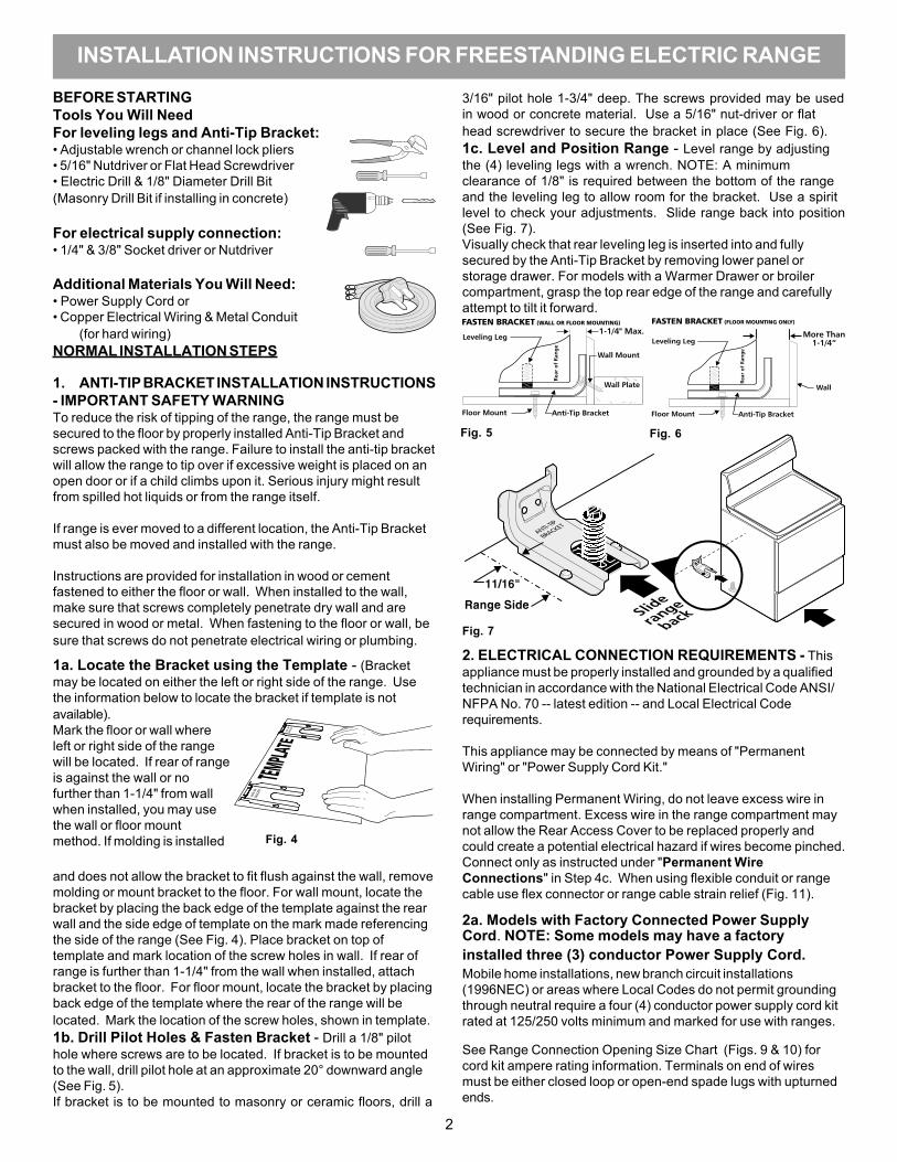
Fig. 7
BEFORE STARTINGTools You Will NeedFor leveling legs and Anti-Tip Bracket:• Adjustable wrench or channel lock pliers• 5/16" Nutdriver or Flat Head Screwdriver• Electric Drill & 1/8" Diameter Drill Bit(Masonry Drill Bit if installing in concrete)
For electrical supply connection:• 1/4" & 3/8" Socket driver or Nutdriver
Additional Materials You Will Need:• Power Supply Cord or• Copper Electrical Wiring & Metal Conduit
(for hard wiring)NORMAL INSTALLATION STEPS
3/16" pilot hole 1-3/4" deep. The screws provided may be usedin wood or concrete material. Use a 5/16" nut-driver or flathead screwdriver to secure the bracket in place (See Fig. 6).1c. Level and Position Range - Level range by adjustingthe (4) leveling legs with a wrench. NOTE: A minimumclearance of 1/8" is required between the bottom of the rangeand the leveling leg to allow room for the bracket. Use a spiritlevel to check your adjustments. Slide range back into position(See Fig. 7).Visually check that rear leveling leg is inserted into and fullysecured by the Anti-Tip Bracket by removing lower panel orstorage drawer. For models with a Warmer Drawer or broilercompartment, grasp the top rear edge of the range and carefullyattempt to tilt it forward.
available).Mark the floor or wall whereleft or right side of the rangewill be located. If rear of rangeis against the wall or nofurther than 1-1/4" from wallwhen installed, you may usethe wall or floor mountmethod. If molding is installed
and does not allow the bracket to fit flush against the wall, removemolding or mount bracket to the floor. For wall mount, locate thebracket by placing the back edge of the template against the rearwall and the side edge of template on the mark made referencingthe side of the range (See Fig. 4). Place bracket on top oftemplate and mark location of the screw holes in wall. If rear ofrange is further than 1-1/4" from the wall when installed, attachbracket to the floor. For floor mount, locate the bracket by placingback edge of the template where the rear of the range will belocated. Mark the location of the screw holes, shown in template.1b. Drill Pilot Holes & Fasten Bracket - Drill a 1/8" pilothole where screws are to be located. If bracket is to be mountedto the wall, drill pilot hole at an approximate 20° downward angle(See Fig. 5).If bracket is to be mounted to masonry or ceramic floors, drill a
Mobile home installations, new branch circuit installations(1996NEC) or areas where Local Codes do not permit groundingthrough neutral require a four (4) conductor power supply cord kitrated at 125/250 volts minimum and marked for use with ranges.
See Range Connection Opening Size Chart (Figs. 9 & 10) forcord kit ampere rating information. Terminals on end of wiresmust be either closed loop or open-end spade lugs with upturnedends.
2
INSTALLATION INSTRUCTIONS FOR FREESTANDING ELECTRIC RANGE
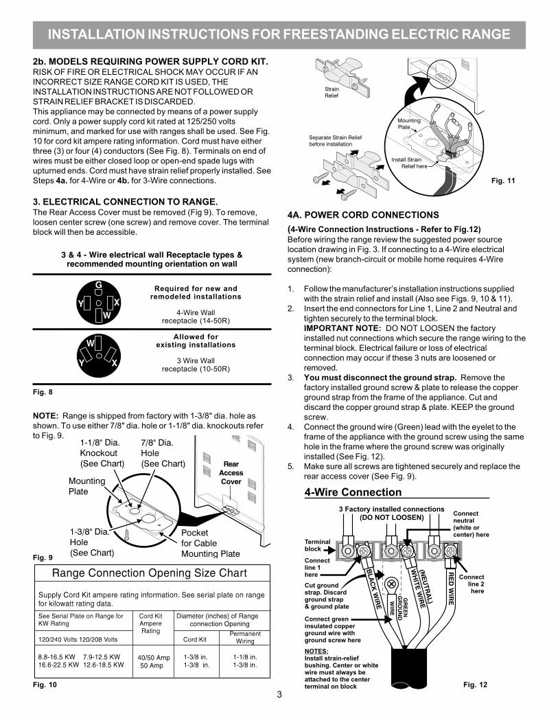
2b. MODELS REQUIRING POWER SUPPLY CORD KIT.RISK OF FIRE OR ELECTRICAL SHOCK MAY OCCUR IF ANINCORRECT SIZE RANGE CORD KIT IS USED, THEINSTALLATION INSTRUCTIONS ARE NOT FOLLOWED ORSTRAIN RELIEF BRACKET IS DISCARDED.This appliance may be connected by means of a power supplycord. Only a power supply cord kit rated at 125/250 voltsminimum, and marked for use with ranges shall be used. See Fig.10 for cord kit ampere rating information. Cord must have eitherthree (3) or four (4) conductors (See Fig. 8). Terminals on end ofwires must be either closed loop or open-end spade lugs withupturned ends. Cord must have strain relief properly installed. SeeSteps 4a. for 4-Wire or 4b. for 3-Wire connections.
3. ELECTRICAL CONNECTION TO RANGE.The Rear Access Cover must be removed (Fig 9). To remove,loosen center screw (one screw) and remove cover. The terminalblock will then be accessible.
Fig. 10
4A. POWER CORD CONNECTIONS
Fig. 11
Fig. 12
(4-Wire Connection Instructions - Refer to Fig.12)Before wiring the range review the suggested power sourcelocation drawing in Fig. 3. If connecting to a 4-Wire electricalsystem (new branch-circuit or mobile home requires 4-Wireconnection):
1. Follow the manufacturer’s installation instructions suppliedwith the strain relief and install (Also see Figs. 9, 10 & 11).
2. Insert the end connectors for Line 1, Line 2 and Neutral andtighten securely to the terminal block.IMPORTANT NOTE: DO NOT LOOSEN the factoryinstalled nut connections which secure the range wiring to theterminal block. Electrical failure or loss of electricalconnection may occur if these 3 nuts are loosened orremoved.
3. You must disconnect the ground strap. Remove thefactory installed ground screw & plate to release the copperground strap from the frame of the appliance. Cut anddiscard the copper ground strap & plate. KEEP the groundscrew.
4. Connect the ground wire (Green) lead with the eyelet to theframe of the appliance with the ground screw using the samehole in the frame where the ground screw was originallyinstalled (See Fig. 12).
5. Make sure all screws are tightened securely and replace therear access cover (See Fig. 9).
3
INSTALLATION INSTRUCTIONS FOR FREESTANDING ELECTRIC RANGE
NOTE: Range is shipped from factory with 1-3/8" dia. hole asshown. To use either 7/8" dia. hole or 1-1/8" dia. knockouts referto Fig. 9.
Fig. 8
Fig. 9
RearAccessCover
3 & 4 - Wire electrical wall Receptacle types &recommended mounting orientation on wall
Required for new andremodeled installations
4-Wire Wallreceptacle (14-50R)
Allowed forexisting installations
3 Wire Wallreceptacle (10-50R)

or 4B. POWER CORD CONNECTIONS(3-Wire Connection Instructions . For existing installations ONLY- Refer to Fig. 13).1. Follow the manufacturer’s installation instructions supplied with the
strain relief and install (Also see Figs. 9, 10 & 11).2. Insert the end connectors for Line 1, Line 2 and Neutral and tighten
securely to the terminal block (See Fig. 13).IMPORTANT NOTE: DO NOT LOOSEN the factory installed nutconnections which secure the range wiring to the terminal block.Electrical failure or loss of electrical connection may occur if these 3nuts are loosened or removed.
3. Make sure all connections are tightened securely and replace the rearaccess cover (See Fig. 9).
Grounding Instructions (3-Wire Connections only): A groundstrap is installed on this range which connects the center terminal of theterminal block (Neutral) to the range chassis. The ground strap isconnected to the range by the center, lowest screw (See Fig. 13). Theground strap must not be removed unless National, State or LocalCodes do not permit use of a ground strap.NOTE: If the ground strap is removed for any reason, a separateground wire must be connected to the separate ground screw attachedto the range chassis and to an adequate ground source.
NOTE: Non-terminated field wire compression connections must beset at 22 in./lbs. or greater. Always use 10 gauge wire or larger.
Fig. 13
4c. 3 & 4-WIRE PERMANENT WIRE CONNECTIONS.3 - Wire Permanent Connection - follow Steps 1,2 & 5 below.4 - Wire Permanent Connection - follow Steps 1 thru 5 below.Before wiring the range, review the suggested power source locationdrawings in Fig. 3. If connecting to a 4-Wire electrical system (new branch-circuit or mobile home requires 4-Wire connection):
1. (3 & 4 - Wire Permanent Connections) Follow the manufacturer’sinstallation instructions supplied with the strain relief and install.
2. (3 & 4 - Wire Permanent Connections) Strip insulation away from theends of the permanent wiring for Line 1, Line 2, Neutral (also strip groundwire on 4-Wire Connections). Tighten all 3 wire leads to the terminalblock (Follow wire locations shown in Fig. 14).IMPORTANT NOTE: DO NOT LOOSEN the factory installed nutconnections which secure the range wiring to the terminal block.Electrical failure or loss of electrical connection may occur if these 3nuts are loosened or removed. NOTE: For 3-Wire PermanentConnections skip Steps 3 & 4 and continue with Step 5.
3. (4-Wire Permanent Connection ONLY) Disconnect the ground strap.Remove the factory installed ground screw & plate to release thefactory installed copper ground strap from frame of the appliance.Cut and discard the copper strap from the terminal block. KEEP theground screw, ground plate and go to Step 4.
4. (4-Wire Permanent Connection ONLY) Connect the ground wire lead(Green) to the frame of the appliance using the ground screw & plate asshown in Fig. 15. Be sure to install using the same hole in the framewhere the ground screw was originally installed.
5. (3 & 4 - Wire Permanent Connections) Make sure all connections aretightened securely and replace the rear access cover (See Fig. 9).
Fig. 14
5. CAREFULLY SLIDE RANGE INTO FINAL LOCATION.Be sure to provide all the adequate clearances and dimensions shown inFigs. 1, 2 & 3 before moving appliance into final location.
Carefully slide range into final position while inserting rear leveling leg intoand FULLY ENGAGING THE ANTI-TIP BRACKET (See Fig. 7). Make sure thepower cord folds into the remaining open floor area behind the range Warmeror storage drawer. Be sure to check the level of the range.
Fig. 15
4
INSTALLATION INSTRUCTIONS FOR FREESTANDING ELECTRIC RANGE
Note: Non-terminated field wire compressionconnections must be set at approximately 22in./lbs. Always use 10 ga. wire or larger.
Serial plate is located on the lower right front frameof the appliance. Alternate location may be undercooktop.
Serial Plate Locations:
5
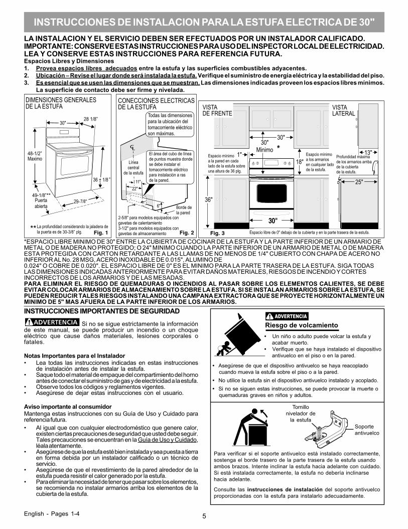
LA INSTALACION Y EL SERVICIO DEBEN SER EFECTUADOS POR UN INSTALADOR CALIFICADO.IMPORTANTE: CONSERVE ESTAS INSTRUCCIONES PARA USO DEL INSPECTOR LOCAL DE ELECTRICIDAD.LEA Y CONSERVE ESTAS INSTRUCCIONES PARA REFERENCIA FUTURA.Espacios Libres y Dimensiones1. Provea espacios libres adecuados entre la estufa y las superficies combustibles adyacentes.2. Ubicación – Revise el lugar donde será instalada la estufa. Verifique el suministro de energía eléctrica y la estabilidad del piso.3. Es esencial que se usen las dimensiones que se muestran. Las dimensiones indicadas proveen los espacios libres mínimos.
La superficie de contacto debe ser firme y nivelada.
*ESPACIO LIBRE MINIMO DE 30" ENTRE LA CUBIERTA DE COCINAR DE LA ESTUFA Y LA PARTE INFERIOR DE UN ARMARIO DEMETAL O DE MADERA NO PROTEGIDO; O 24" MINIMO CUANDO LA PARTE INFERIOR DE UN ARMARIO DE METAL O DE MADERAESTA PROTEGIDA CON CARTON RETARDANTE A LAS LLAMAS DE NO MENOS DE 1/4" CUBIERTO CON CHAPA DE ACERO NOINFERIOR AL No. 28 MSG, ACERO INOXIDABLE DE 0.015", ALUMINO DE0.024" O COBRE DE 0.020". EL ESPACIO LIBRE DE 0" ES EL MINIMO PARA LA PARTE TRASERA DE LA ESTUFA. SIGA TODASLAS DIMENSIONES INDICADAS ANTERIORMENTE PARA EVITAR DAÑOS MATERIALES, RIESGOS DE INCENDIO Y CORTESINCORRECTOS DE LOS ARMARIOS Y DE LAS MESADAS.PARA ELIMINAR EL RIESGO DE QUEMADURAS O INCENDIOS AL PASAR SOBRE LOS ELEMENTOS CALIENTES, SE DEBEEVITAR COLOCAR ARMARIOS DE ALMACENAMIENTO SOBRE LA ESTUFA. SI SE INSTALAN ARMARIOS SOBRE LA ESTUFA, SEPUEDEN REDUCIR TALES RIESGOS INSTALANDO UNA CAMPANA EXTRACTORA QUE SE PROYECTE HORIZONTALMENTE UNMINIMO DE 5" MAS AFUERA DE LA PARTE INFERIOR DE LOS ARMARIOS.
English - Pages 1-4
Si no se sigue estrictamente la informaciónde este manual, se puede producir un incendio o un choqueeléctrico que cause daños materiales, lesiones corporales ofatales.
Notas Importantes para el Instalador• Lea todas las instrucciones indicadas en estas instrucciones
de instalación antes de instalar la estufa.• Saque todo el material de empaque del compartimiento del horno
antes de conectar el suministro de gas y de electricidad a la estufa.• Observe todos los códigos y reglamentos vigentes.• Asegúrese de dejar estas instrucciones con el usuario.
Aviso importante al consumidorMantenga estas instrucciones con su Guía de Uso y Cuidado parareferencia futura.• Al igual que con cualquier electrodoméstico que genere calor,
existen ciertas precauciones de seguridad que usted debe seguir.Tales precauciones se encuentran en la Guía de Uso y Cuidado,léala atentamente.
• Asegúrese de que la estufa esté bien instalada y sea puesta a tierraen forma debida por un instalador calificado o un técnico deservicio.
• Asegúrese de que el revestimiento de la pared alrededor de laestufa pueda resistir el calor generado por la estufa.
• Para eliminar la necesidad de tener que pasar sobre los elementos,se recomienda no instalar armarios arriba los elementos de lacubierta de la estufa.
INSTRUCCIONES IMPORTANTES DE SEGURIDAD
INSTRUCCIONES DE INSTALACION PARA LA ESTUFA ELECTRICA DE 30"
Fig. 1 Fig. 2 Fig. 3
30"
• Asegúrese de que el dispositivo antivuelco se haya reacopladocuando mueva la estufa sobre el piso o a la pared.
• No utilice la estufa sin el dispositivo antivuelco instalado y acoplado.• Si no se siguen estas instrucciones, se puede provocar la muerte o
quemaduras graves en niños y adultos.
Para verificar si el soporte antivuelco está instalado correctamente,sostenga el borde trasero de la parte trasera de la estufa usandoambos brazos. Intente inclinar la estufa hacia adelante con cuidado.Si está instalada correctamente, la estufa no debería inclinarsehacia adelante.
Consulte las instrucciones de instalación del soporte antivuelcoproporcionadas con la estufa para instalarlo adecuadamente.
WARNING: Riesgo de volcamiento• Un niño o adulto puede volcar la estufa y
acabar muerto.• Verifique que se haya instalado el dispositivo
antivuelco en el piso o en la pared.
Tornillonivelador de
la estufaSoporteantivuelco
6
Fig. 7
Costadode la
estufa
11/16"
Deslice la
estufa
hacia atrás
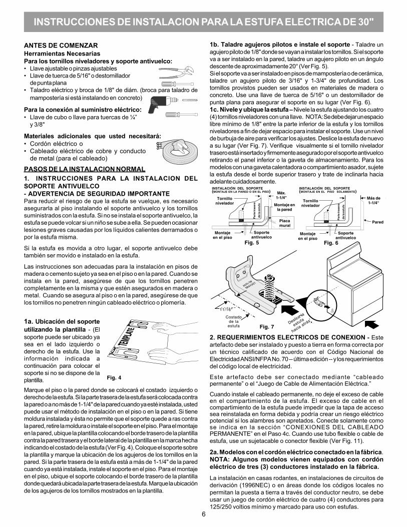
ANTES DE COMENZARHerramientas NecesariasPara los tornillos niveladores y soporte antivuelco:• Llave ajustable o pinzas ajustables• Llave de tuerca de 5/16" o destornillador
de punta plana• Taladro eléctrico y broca de 1/8" de diám. (broca para taladro de
mampostería si está instalando en concreto)
Para la conexión al suministro eléctrico:• Llave de cubo o llave para tuercas de ¼”
y 3/8"
Materiales adicionales que usted necesitará:• Cordón eléctrico o• Cableado eléctrico de cobre y conducto
de metal (para el cableado)
PASOS DE LA INSTALACION NORMAL1. INSTRUCCIONES PARA LA INSTALACION DELSOPORTE ANTIVUELCO- ADVERTENCIA DE SEGURIDAD IMPORTANTEPara reducir el riesgo de que la estufa se vuelque, es necesarioasegurarla al piso instalando el soporte antivuelco y los tornillossuministrados con la estufa. Si no se instala el soporte antivuelco, laestufa se puede volcar si un niño se sube a ella. Se pueden ocasionarlesiones graves causadas por los líquidos calientes derramados opor la estufa misma.
Si la estufa es movida a otro lugar, el soporte antivuelco debetambién ser movido e instalado en la estufa.
Las instrucciones son adecuadas para la instalación en pisos demadera o cemento sujeto ya sea en el piso o en la pared. Cuando seinstala en la pared, asegúrese de que los tornillos penetrencompletamente en la misma y que estén asegurados en madera ometal. Cuando se asegura al piso o en la pared, asegúrese de quelos tornillos no penetren ningún cableado eléctrico o plomería.
1b. Taladre agujeros pilotos e instale el soporte - Taladre unagujero piloto de 1/8" donde se vayan a instalar los tornillos. Si el soporteva a ser instalado en la pared, taladre un agujero piloto en un ángulodescente de aproximadamente 20° (Ver Fig. 5).Si el soporte va a ser instalado en pisos de mampostería o de cerámica,taladre un agujero piloto de 3/16" y 1-3/4" de profundidad. Lostornillos provistos pueden ser usados en materiales de madera oconcreto. Use una llave de tuerca de 5/16" o un destornillador depunta plana para asegurar el soporte en su lugar (Ver Fig. 6).1c. Nivele y ubique la estufa – Nivele la estufa ajustando los cuatro(4) tornillos niveladores con una llave. NOTA: Se debe dejar un espaciolibre mínimo de 1/8" entre la parte inferior de la estufa y los tornillosniveladores a fin de dejar espacio para instalar el soporte. Use un nivelde burbuja de aire para verificar los ajustes. Deslice la estufa de nuevoa su lugar (Ver Fig. 7). Verifique visualmente si el tornillo niveladortrasero está insertado y firmemente asegurado por el soporte antivuelcoretirando el panel inferior o la gaveta de almacenamiento. Para losmodelos con una gaveta calentadora o compartimiento asador, sujetela estufa desde el borde superior trasero y trate de inclinarla haciaadelante cuidadosamente.
2. REQUERIMIENTOS ELECTRICOS DE CONEXION - Esteartefacto debe ser instalado y puesto a tierra en forma correcta porun técnico calificado de acuerdo con el Código Nacional deElectricidad ANSI/NFPA No. 70 -- última edición -- y los requerimientosdel código local de electricidad.
Este artefacto debe ser conectado mediante “cableadopermanente” o el “Juego de Cable de Alimentación Eléctrica.”
Cuando instale el cableado permanente, no deje el exceso de cableen el compartimiento de la estufa. El exceso de cable en elcompartimiento de la estufa puede impedir que la tapa de accesosea reinstalada en forma debida y podría crear un riesgo eléctricopotencial si los alambres son apretados. Conecte solamente comose indica en la sección “CONEXIONES DEL CABLEADOPERMANENTE” en el Paso 4c. Cuando use tubo flexible o cable deestufa, use un sujetacable o conector flexible (Ver Fig. 11).
2a. Modelos con el cordón eléctrico conectado en la fábrica.NOTA: Algunos modelos vienen equipados con cordóneléctrico de tres (3) conductores instalado en la fábrica.
La instalación en casas rodantes, en instalaciones de circuitos dederivación (1996NEC) o en áreas donde los códigos locales nopermitan la puesta a tierra a través del conductor neutro, se debeusar un juego de cordón eléctrico de cuatro (4) conductores para125/250 voltios mínimo y marcado para uso con estufas.
Fig. 4
1a. Ubicación del soporteutilizando la plantilla - (Elsoporte puede ser ubicado yasea en el lado izquierdo oderecho de la estufa. Use lainformación indicada acontinuación para colocar elsoporte si no se dispone de laplantilla.Marque el piso o la pared donde se colocará el costado izquierdo oderecho de la estufa. Si la parte trasera de la estufa será colocada contrala pared o a no más de 1-1/4" de la pared cuando ya esté instalada, ustedpuede usar el método de instalación en el piso o en la pared. Si tienemoldura instalada y ésta no permite que el soporte quede a ras contrala pared, retire la moldura o instale el soporte en el piso. Para el montajeen la pared, ubique la plantilla colocando el borde trasero de la plantillacontra la pared trasera y el borde lateral de la plantilla en la marca hechaindicando el costado de la estufa (Ver Fig. 4). Coloque el soporte sobrela plantilla y marque la ubicación de los agujeros de los tornillos en lapared. Si la parte trasera de la estufa está a más de 1-1/4" de la paredcuando ya está instalada, instale el soporte en el piso. Para el montajeen el piso, ubique el soporte colocando el borde trasero de la plantilladonde quedará ubicada la parte trasera de la estufa. Marque la ubicaciónde los agujeros de los tornillos mostrados en la plantilla.
Fig. 5 Fig. 6
INSTALACIÓN DEL SOPORTE(MONTAJE EN LA PARED O EN EL PISO)
INSTALACIÓN DEL SOPORTE(MONTAJE EN EL PISO SOLAMENTE)
Tornillonivelador Tornillo
nivelador
Máx.1-1/4" Más de
1-1/4"Montaje enla pared
Placamural
Montajeen el piso
Montajeen el piso
Soporteantivuelco
Soporteantivuelco
Pared
Par
te tr
aser
a
de
la e
stu
fa
Par
te tr
aser
a
de
la e
stu
fa
INSTRUCCIONES DE INSTALACION PARA LA ESTUFA ELECTRICA DE 30"
7
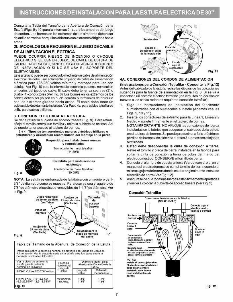
NOTA: La estufa es embarcada de la fábrica con un agujero de 1-3/8" de diámetro como se muestra. Para usar ya sea el agujero de7/8" de diámetro o los discos removibles de 1-1/8" de diámetro. Verla Fig. 9.
Fig. 8
Fig. 9
3 y 4 - Tipos de tomacorrientes murales eléctricos trifilares otetrafilares y orientación recomendada del montaje en la pared
Requerido para instalaciones nuevasy remodeladas
Tomacorriente mural tetrafilar(14-50R)
Permitido para instalacionesexistentes
Tomacorriente mural tetrafilar(10-50R)
Consulte la Tabla del Tamaño de la Abertura de Conexión de laEstufa (Figs. 9 y 10) para la información sobre los amperes del juegode cordón. Los bornes en los extremos de los almabres deben serde anillo cerrado u horquillas abiertas con extremos dirigidos haciaarriba.2b. MODELOS QUE REQUIEREN EL JUEGO DE CABLEDE ALIMENTACION ELECTRICAPUEDE OCURRIR RIESGO DE INCENDIO O CHOQUEELECTRICO SI SE USA UN JUEGO DE CABLE DE ESTUFA DECALIBRE INCORRECTO, SI NO SE SIGUEN LAS INSTRUCCIONESDE INSTALACION O SI NO SE USA EL SOPORTE DELSUJETACABLES.Este artefacto puede ser conectado mediante un cable de alimentacióneléctrica. Se debe usar solamente un juego de cable de alimentacióneléctrica para 125/250 voltios mínimo y marcado para uso conestufas. Ver Fig. 10 para la información sobre la potencia nominal enamperios del juego de cable. El cable debe tener ya sea tres (3) ocuatro (4) conductores (Ver Fig. 8). Los bornes en los extremos de loscables deben ser ya sea en bucle cerrado o terminales de horquillacon los extremos girados hacia arriba. El cable debe tener unsujetacable debidamente instalado. Ver Paso 4a. para cables tetrafilareso 4b. para cables trifilares.
3. CONEXION ELECTRICA A LA ESTUFA.Se debe retirar la cubierta de acceso trasera (Fig. 9). Para retirar,afloje el tornillo central (un tornillo) y retire la cubierta de acceso. Asíse puede tener acceso al tablero de bornes.
Tabla del Tamaño de la Abertura de Conexión de la Estufa
Informació sobre la potencia nominal en amperios del Juego de Cable deAlimentación. Ver la placa de serie en la estufa para los datos sobre lapotencia nominal en kilovatios.
Ver la placa de serie en laestufa para la potencianominal en kilovatios
120/240 Voltios 120/208 Voltios
Diámetro (pulg.) de laAbertura de Conexión de la
Estufa
PotenciaNominal delJuego de
cable Juego decable
CableadoPermanente
1-3/8"1-3/8"
1-1/8"1-3/8"
40/50 Amp.50 Amp.
8,8-16,5 KW 7,9-12,5 KW16,6-22,5 KW 12,6-18,5 KW
Fig. 10
Cubiertade
accesotrasera
Disco removiblede 29mm de diám.
(Ver Tabla)
Agujero de22 mm de diám.
(Ver Tabla)
Placa demontaje
Agujero de35 mm de diám.
(Ver Tabla) Cavidad para laplaca de montaje
del cable
Fig. 11
Sujetacable
Separe elsujetacable antesde la instalación
4A. CONEXIONES DEL CORDON DE ALIMENTACION(Instrucciones para Conexión Tetrafilar - Consulte la Fig.12)Antes del cableado de la estufa, revise los dibujos de las ubicacionessugeridas para la fuente de alimentación en la Fig. 3. Si se va aconectar a un sistema eléctrico tetrafilar (los circuitos de derivaciónnuevos o las casas rodantes requieren conexión tetrafilar):1. Siga las instrucciones de instalación del fabricante
suministradas con el sujetacable e instale (Además vea lasFigs. 9, 10 y 11).
2. Inserte los conectores de extremo para la Línea 1, Línea 2 yNeutro y apriete firmemente en el tablero de bornes.NOTA IMPORTANTE: NO AFLOJE las conexiones de tuercainstaladas en la fábrica que aseguran el cableado de la estufaen el tablero de bornes. Se puede producir una falla eléctrica opérdida de la conexión eléctrica si estas 3 tuercas son aflojadaso retiradas.
3. Usted debe desconectar la cinta de conexión a tierra.Retire el tornillo y placa de tierra instalada en la fábrica parasoltar la cinta de conexión a tierra de cobre del marco delelectrodoméstico. CONSERVE el tornillo de tierra.
4. Conecte el alambre de puesta a tierra (Verde) con el ojal en elmarco del electrodoméstico con el tornillo de tierra usando elmismo agujero del marco donde estaba originalmente instaladoel tornillo de tierra (Ver Fig. 12).
5. Asegúrese de que todas las tuercas estén firmemente apretadasy vuelva a colocar la cubierta de acceso trasera (Ver Fig. 9).
Fig. 12
Placa demontaje
Instaleaquí el
sujetacable
Conecte aquíel alambre de cobre verdeaislado de puesta a tierracon el tornillo de tierra
NOTAS:Instale el buje sujetacable.El alambre central o blancodebe estar siempreinstalado en el bornecentral del tablero debornes.
ConecteLínea 2aquí
Conexión TetrafilarConexiones instaladas en la fábrica
(NO AFLOJAR)
Tablero debornes
ConecteLínea 1aquí
Corte la cintade conexión atierra. Descarte la cinta yla placa de conexión atierra
Conecte aquí elalambre neutro(blanco o central)
AL
AM
BR
EN
EG
RO
AL
AM
BR
EB
LA
NC
O(N
EU
TR
O)
AL
AM
BR
ER
OJO
INSTRUCCIONES DE INSTALACION PARA LA ESTUFA ELECTRICA DE 30"
8
4c. CONEXIONES DEL CABLEADO PERMANENTE TRIFILAR YTETRAFILAR.3 - Conexión trifilar permanente - siga los pasos 1, 2 y 5 incluidos a continuación.4 - Conexión tetrafilar permanente - siga los pasos 1 al 5 que se encuentran másabajo.
Antes del cableado de la estufa, examine los dibujos de la ubicaciónsugerida para la fuente de alimentación en la Fig. 3. Si está conectando a unsistema eléctrico tetrafilar, (un circuito de derivación nuevo o casa rodanterequieren conexión tetrafilar):1. (Conexiones permanentes trifilares y tetrafilares) Siga las instrucciones
de instalación del fabricante suministradas con el sujetacable e instale.2. (Conexiones permanentes trifilares y tetrafilares) Desforre el aislamiento
de los extremos del cableado permanente para la Línea 1, Línea 2, Neutro(además desforre el alambre de conexión a tierra en las conexionestetrafilares). Apriete los 3 conductores hacia el tablero de bornes (Siga lasubicaciones de los alambres que se muestran en la Fig. 14).NOTA IMPORTANTE: NO AFLOJE las conexiones de tuerca instaladas enla fábrica que aseguran el cableado de la estufa en el tablero de bornes. Sepuede producir una falla eléctrica o pérdida de la conexión eléctrica si estas3 tuercas son aflojadas o retiradas. NOTA: Para las conexionespermanentes trifilares omita los Pasos 3 y 4 y continúe con el Paso5.
3. (Conexión permanente tetrafilar SOLAMENTE) Desconecte la cinta deconexión a tierra. Retire el tornillo y placa de tierra instalada en la fábricapara soltar la cinta de conexión a tierra de cobre del marco delelectrodoméstico. CONSERVE el tornillo de tierra, la placa de tierra y sigacon el Paso 4.
4. (Conexión permanente tetrafilar SOLAMENTE) Conecte el alambreterminal de puesta a tierra (Verde) al marco del electrodoméstico usandoel tornillo y la placa de conexión a tierra, como se muestra en la Fig. 15.Asegúrese de instalarlo usando el mismo agujero del marco donde estabaoriginalmente instalado el tornillo de tierra.
5. (Conexiones permanentes trifilares y tetrafilares) Asegúrese de quetodas las tuercas estén firmemente apretadas y vuelva a colocar la cubierta deacceso trasera (Ver Fig. 9).
NOTA: Las conexiones de compresión no terminadas del cableado decampo deben ser ajustadas a aproximadamente 22 pulg./lbs.
5. DESLICE CON CUIDADO LA ESTUFA HASTA SU LUGARDEFINITIVO.
Asegúrese de proveer todos los espacios libres adecuados y lasdimensiones mostradas en las Figs. 1, 2 y 3 en la Página 1 antes de moverla estufa a su lugar definitivo.
Deslice cuidadosamente la estufa hacia la abertura del gabinete a la vez queinserta el tornillo nivelador trasero en el SOPORTE ANTIVUELCO VERFICANDOQUE QUEDE BIEN ENGANCHADO (Ver Fig. 7). Asegúrese de que el cordón dealimentación quede plegado en el resto del área abierta del piso detrás de lagaveta de almacenamiento o gaveta calentadora de la estufa. Asegúrese deverificar la nivelación de la estufa.
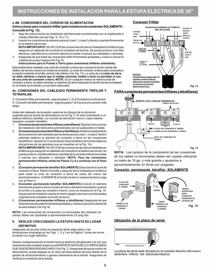
o 4B. CONEXIONES DEL CORDON DE ALIMENTACIONInstrucciones para conexión trifilar (para instalaciones existentes SOLAMENTE -Consulte la Fig. 13).1. Siga las instrucciones de instalación del fabricante suministradas con el sujetacable e
instale (Además vea las Figs. 9, 10 y 11).2. Inserte los conectores de extremo para la Línea 1, Línea 2 y Neutro y apriete firmemente
en el tablero de bornes.NOTA IMPORTANTE: NO AFLOJE las conexiones de tuerca instaladas en la fábrica queaseguran el cableado de la estufa en el tablero de bornes. Se puede producir una fallaeléctrica o pérdida de la conexión eléctrica si estas 3 tuercas son aflojadas o retiradas.
3. Asegúrese de que todas las conexiones estén firmemente apretadas y vuelva a colocar lacubierta de acceso trasera (Ver Fig. 9).Instrucciones para la Puesta a Tierra (para conexiones trifilares solamente):
Esta estufa tiene instalada una cinta de conexión a tierra que conecta el borne central deltablero de bornes (neutro) al chasis de la estufa. La cinta de conexión a tierra está conectada ala estufa mediante el tornillo central más inferior (Ver Fig. 13). La cinta de conexión de tierrano debe retirarse a menos que el código nacional, estatal o local no permitan el usode una cinta de conexión a tierra. NOTA: Si por cualquier motivo se retira la cinta deconexión a tierra, se debe conectar un alambre de tierra separado al tornillo de tierra instaladoen el chasis de la estufa y a una tierra adecuada.
Conexión permanente tetrafilar SOLAMENTE
PLACA DECONEXIONA TIERRA
TORNILLO DECONEXION A
TIERRA
INSTRUCCIONES DE INSTALACION PARA LA ESTUFA ELECTRICA DE 30"
CABLETERMINAL DE
CONEXIONA TIERRA
TIERRAAPROPIADAPARACONEXIONPERMANENTETETRAFILAR
TIERRA
Fig. 15
NOTA: Los campos de la compresión de las conexionesde los cables no terminadas deben ser usadas utilizandoun cable de 10 ga. o más grande y ajustarlos aaproximadamente 22 libras por pulgadas
Conexión Trifilar
BL
AN
CO
ConecteLínea 1aquí
NOTAS:Instale el buje sujetacable. Elalambre central o blancodebe estar siempre instaladoen el borne central deltablero de bornes.
Tablero debornes
Fig. 13
ConecteLínea 2aquí
Conecte elalambreneutro(blanco ocentral)
AL
AM
BR
ER
OJO
(NE
UT
RO
)
AL
AM
BR
E
CINTA DECONEXIONA TIERRA
TORNILLO YPLACADE TIERRA
Conexiones instaladas en la fábrica(NO AFLOJAR)
AL
AM
BR
E
NE
GR
O
PARA conexiones permanentes trifilares y tetrafilares)
Ubicación de la placa de serie:
La placa de serie está ubicada en el costado derecho del marcodelantero inferior del electrodoméstico.
TORNILLO DE CONEXION A TIERRA
Fig. 14
CINTA DE CONEXION DETIERRA
APRIETE LOS 3 CABLES TERMINALESTablero de bornes
Línea 1 Línea 2Neutro
PLACA DE CONEXION A TIERRA
Ubicación de la placa de serie: