
En DHomesb SLM v40
141
This document is exclusive property of Cisco Systems, Inc. Permission is granted to print and copy this document for non-commercial distribution and exclusive use by instructors in the CCNA Discovery Networking for Home and Small Businesses course as part of an official Cisco Networking Academy.
Transcript of En DHomesb SLM v40

This document is exclusive property of Cisco Systems, Inc. Permission is granted to print and copy this document for non-commercial distribution and exclusive use by instructors in the CCNA Discovery Networking for Home and Small Businesses course as part of an official Cisco Networking Academy.

All contents are Copyright © 1992–2007 Cisco Systems, Inc. All rights reserved. This document is Cisco Public Information. Page 1 of 6
Lab 1.3.2 Determining Data Storage Capacity
Objectives • Determine the amount of RAM (in MB) installed in a PC. • Determine the size of the hard disk drive (in GB) installed in a PC. • Determine the used and available space on the hard disk drive (in GB). • Check other types of storage devices (floppy, CD-ROM, DVD).
Background / Preparation The storage capacity of many PC components is measured in megabytes (MB) and gigabytes (GB). These components include RAM, hard disk drives, and optical media, such as CDs and DVDs. In this lab, you will determine the capacity and space available for various computer components.
The following resources are required:
• Computer with Windows XP installed
CCNA Discovery
Networking for Home and Small Businesses
CCNA Discovery
Networking for Home and Small Businesses
All contents are Copyright © 1992–2007 Cisco Systems, Inc. All rights reserved. This document is Cisco Public Information. Page 2 of 6
Step 1: Identify the RAM in a computer a. With Windows XP, there are two ways to view control panels: Classic View and Category View. The
options available depend on which one of these two views you are using. If you see the Switch to Category View option on the left, you are currently in the classic view mode. If Switch to Classic View is displayed, you are currently in Category View mode. For this step, you want to use Classic View mode.
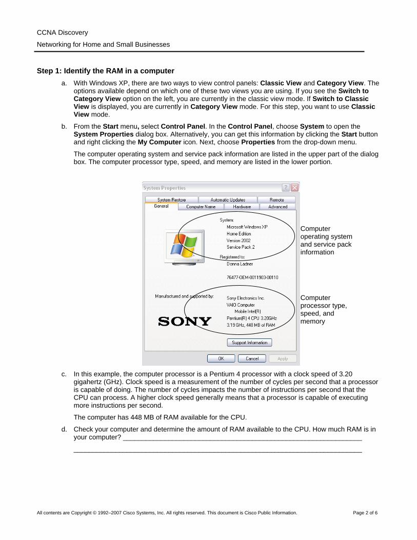
b. From the Start menu, select Control Panel. In the Control Panel, choose System to open the System Properties dialog box. Alternatively, you can get this information by clicking the Start button and right clicking the My Computer icon. Next, choose Properties from the drop-down menu.
The computer operating system and service pack information are listed in the upper part of the dialog box. The computer processor type, speed, and memory are listed in the lower portion.
c. In this example, the computer processor is a Pentium 4 processor with a clock speed of 3.20
gigahertz (GHz). Clock speed is a measurement of the number of cycles per second that a processor is capable of doing. The number of cycles impacts the number of instructions per second that the CPU can process. A higher clock speed generally means that a processor is capable of executing more instructions per second.
The computer has 448 MB of RAM available for the CPU.
d. Check your computer and determine the amount of RAM available to the CPU. How much RAM is in your computer? _______________________________________________________________
____________________________________________________________________________
Computer operating system and service pack information
Computer processor type, speed, and memory
CCNA Discovery
Networking for Home and Small Businesses
All contents are Copyright © 1992–2007 Cisco Systems, Inc. All rights reserved. This document is Cisco Public Information. Page 3 of 6
Step 2: Determine the size of the hard disk drive a. Double-click the My Computer icon on your computer desktop. If you do not have a My Computer
icon, click Start and choose My Computer.
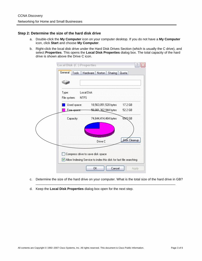
b. Right-click the local disk drive under the Hard Disk Drives Section (which is usually the C drive), and select Properties. This opens the Local Disk Properties dialog box. The total capacity of the hard drive is shown above the Drive C icon.
c. Determine the size of the hard drive on your computer. What is the total size of the hard drive in GB? ____________________________________________________________________________
d. Keep the Local Disk Properties dialog box open for the next step.
CCNA Discovery
Networking for Home and Small Businesses
All contents are Copyright © 1992–2007 Cisco Systems, Inc. All rights reserved. This document is Cisco Public Information. Page 4 of 6
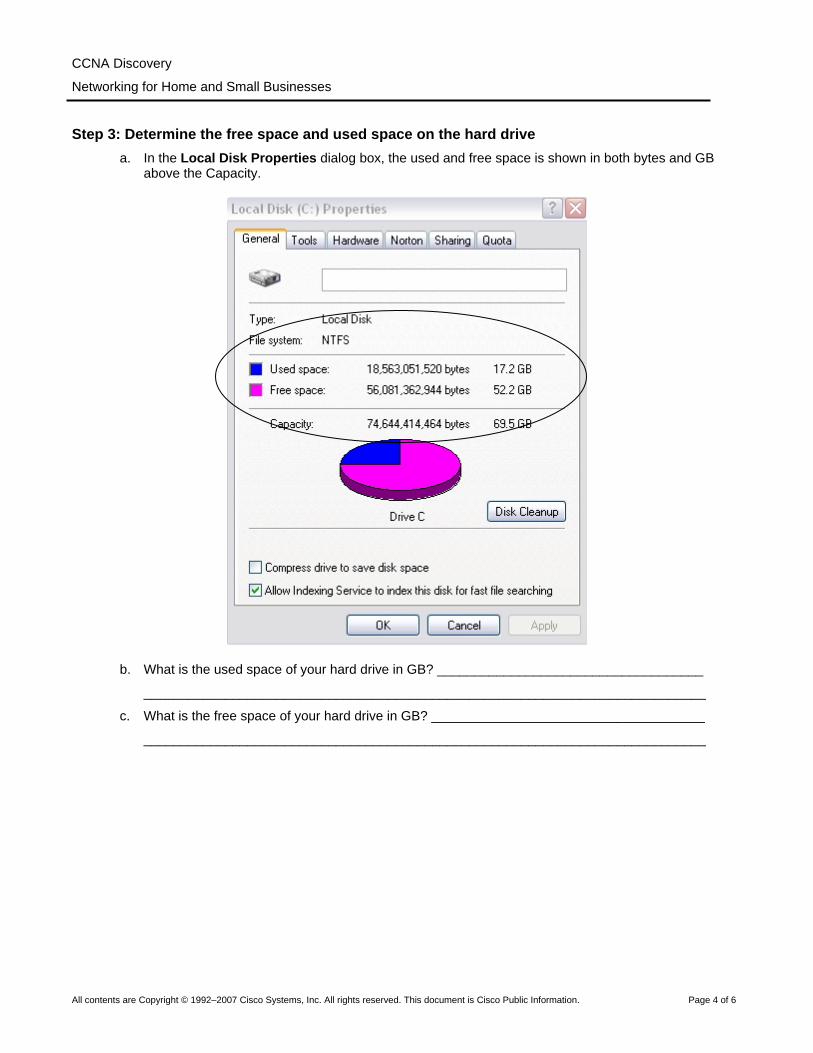
Step 3: Determine the free space and used space on the hard drive a. In the Local Disk Properties dialog box, the used and free space is shown in both bytes and GB
above the Capacity.
b. What is the used space of your hard drive in GB? ____________________________________
____________________________________________________________________________
c. What is the free space of your hard drive in GB? _____________________________________
____________________________________________________________________________

CCNA Discovery
Networking for Home and Small Businesses
All contents are Copyright © 1992–2007 Cisco Systems, Inc. All rights reserved. This document is Cisco Public Information. Page 5 of 6
Step 4: Check for other storage devices a. Right-click the Start button and select Explore. Select My Computer in the left pane.
b. How many drive letters are shown in the window that appears? _________________________
____________________________________________________________________________
c. Right-click on a drive icon other than C: and select Properties. The Removable Disk Properties window appears.
d. Select the Hardware tab, which provides information on each device and whether it is working properly.

CCNA Discovery
Networking for Home and Small Businesses
All contents are Copyright © 1992–2007 Cisco Systems, Inc. All rights reserved. This document is Cisco Public Information. Page 6 of 6
Step 5: Reflection a. Why is it important to know the amount of RAM in your computer?
____________________________________________________________________________
____________________________________________________________________________
b. Why is the size of a hard drive as well as the space being used important?
____________________________________________________________________________
____________________________________________________________________________
____________________________________________________________________________
All contents are Copyright © 1992–2007 Cisco Systems, Inc. All rights reserved. This document is Cisco Public Information. Page 1 of 5
Lab 1.3.3 Determining the Screen Resolution of a Computer Objectives
• Determine the current screen resolution of a PC monitor. • Determine the maximum resolution for the highest color quality. • Calculate the number of pixels needed for resolution settings. • Identify the type of monitor and graphics card installed.
Background / Preparation The resolution of a monitor determines the quality of the screen display. The resolution is determined by the number of horizontal and vertical picture elements (pixels) that are used to produce the image on the monitor. The number of pixels is typically predefined by the manufacturers of graphics cards and PC monitors. The highest number of pixels that a monitor and graphics card can support is referred to as maximum resolution. An example of maximum resolution is 1280 x1024, which means the display is composed of 1280 horizontal pixels and 1024 vertical pixels. The higher the resolution is set, the sharper the display image. The maximum resolution of a PC monitor and the number of colors the monitor can display are determined by two factors:
• Capability of the monitor • Capability of the graphics card, especially the amount of onboard memory
The following resources are required:
• Computer with Windows XP installed
Step 1: Determine the current screen resolution a. To view the current screen resolution and color quality settings, right-click on any empty space on the
desktop and select Properties from the context menu. In the Display Properties window, select the Settings tab.
You can also access Display Properties by opening the Control Panel and clicking the Display icon.
CCNA Discovery
Networking for Home and Small Businesses

CCNA Discovery
Networking for Home and Small Businesses
All contents are Copyright © 1992–2007 Cisco Systems, Inc. All rights reserved. This document is Cisco Public Information. Page 2 of 5
b. Use the Display Properties Settings tab to record the current settings on your PC:
The screen resolution is (H by V) ______________________________________________
The horizontal resolution is: __________________________________________________
The vertical resolution is: ____________________________________________________
The color quality value is: ____________________________________________________
Step 2: Determine the maximum resolution for the highest color quality The slide bar under Screen resolution is used to configure the desired resolution.
a. Move the slide bar to see the range of screen resolutions that are available on your PC. (The range is determined by the operating system when it identifies the display card and the monitor.)
b. Use the Display Properties Settings tab to fill out the following table for the current settings on your PC:
Minimum screen resolution Maximum screen resolution Available color quality settings
CCNA Discovery
Networking for Home and Small Businesses
All contents are Copyright © 1992–2007 Cisco Systems, Inc. All rights reserved. This document is Cisco Public Information. Page 3 of 5
Step 3: Calculate the pixels for current and maximum resolution settings The display on the screen consists of rows of pixels. The number of pixels in each row is the horizontal resolution. The number of rows is the vertical resolution. To determine the total number of pixels in a screen resolution, you multiply the horizontal resolution by the vertical resolution. For example, if the current resolution is 1280 x 1024, the total number of pixels is 1280 times 1024, or 1,310,720.
a. Calculate the total number of pixels for the lowest resolution: ___________________________
b. Calculate the total number of pixels for the maximum resolution: ________________________
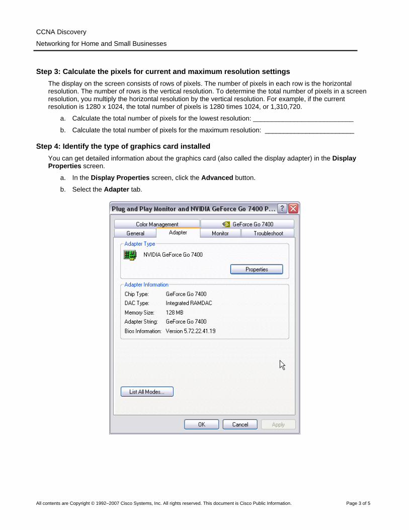
Step 4: Identify the type of graphics card installed You can get detailed information about the graphics card (also called the display adapter) in the Display Properties screen.
a. In the Display Properties screen, click the Advanced button.
b. Select the Adapter tab.

CCNA Discovery
Networking for Home and Small Businesses
All contents are Copyright © 1992–2007 Cisco Systems, Inc. All rights reserved. This document is Cisco Public Information. Page 4 of 5
c. Use the information found in the Adapter tab to complete the following table:
Graphics card manufacturer and model (Adapter Type)
Graphics memory on card (Memory Size)
Step 5: Identify the type of monitor and available refresh rates You can get detailed information about the monitor in the Display Properties screen. The screen refresh rate determines the number of times per second the screen is illuminated or redrawn. A refresh rate of 60 hertz means the screen is illuminated 60 times per second. Higher refresh rates provide less screen flicker, which reduces eye strain, but may adversely affect the monitor. You should set the refresh rate to the highest level the monitor can safely support.

CCNA Discovery
Networking for Home and Small Businesses
All contents are Copyright © 1992–2007 Cisco Systems, Inc. All rights reserved. This document is Cisco Public Information. Page 5 of 5
a. Click on the Monitor tab to see the monitor type and current refresh rate.
b. Use the information found in the Monitor tab to complete the following table:
Monitor type
Supported refresh rates
c. What can occur if you select a refresh rate that is higher than what the monitor can safely display? ____________________________________________________________________________
All contents are Copyright © 1992–2007 Cisco Systems, Inc. All rights reserved. This document is Cisco Public Information. Page 1 of 12
Lab 1.5.3 Installing a Printer and Verifying Operation Objectives
• Manually install a printer using the default Windows XP driver. • Verify printer and driver installation and troubleshoot any problems. • Download and install the most recent driver from the printer manufacturer.
Background / Preparation Many home and small office printers are plug-and-play, which means that Windows XP automatically discovers the printer and installs a functional driver. However, if you know the process for manually installing a printer and updating the printer driver, you have the knowledge to troubleshoot many types of printer problems.
In this lab, you will install a virtual printer on a Windows XP workstation. This lab is designed to work without an actual printer, but most steps are exactly the same for connecting a physical printer.
The following resources are required:
• Computer with Window XP installed • Internet connection
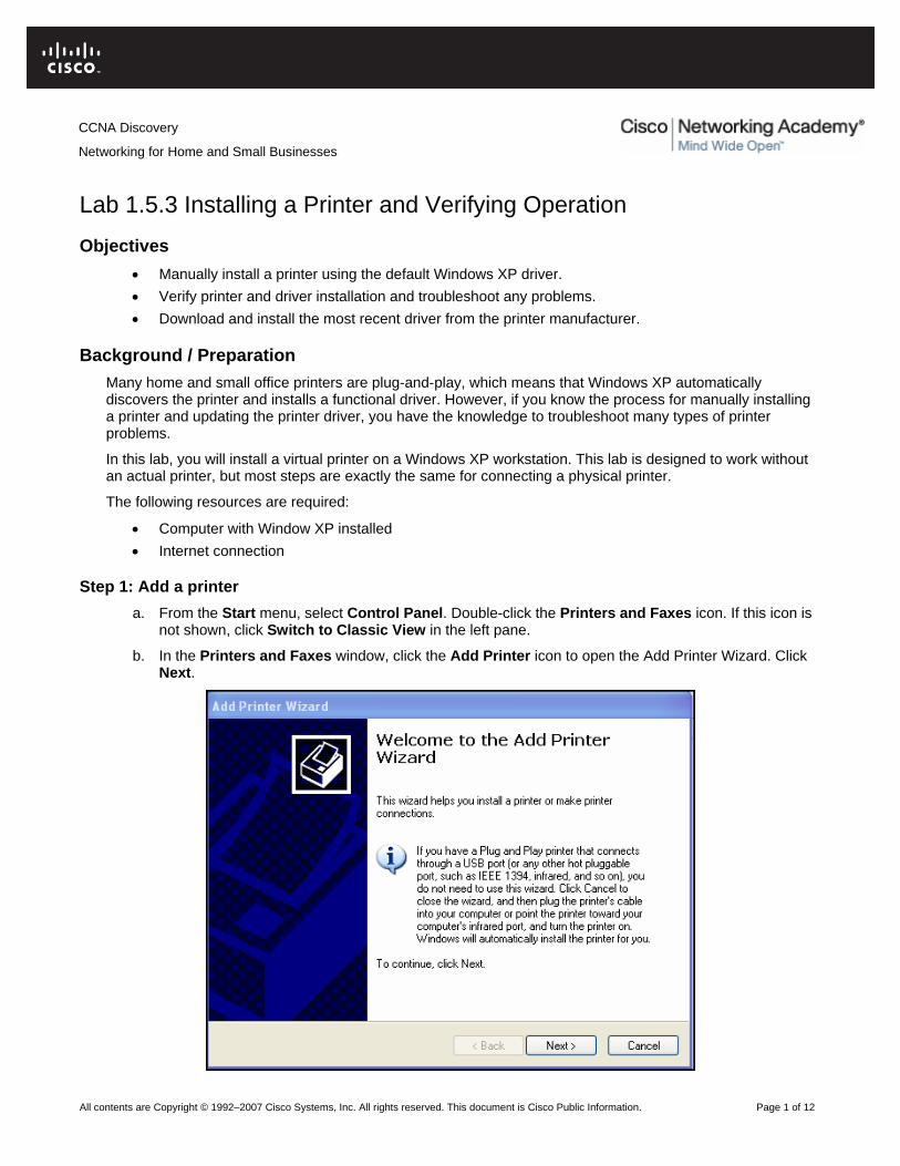
Step 1: Add a printer a. From the Start menu, select Control Panel. Double-click the Printers and Faxes icon. If this icon is
not shown, click Switch to Classic View in the left pane.
b. In the Printers and Faxes window, click the Add Printer icon to open the Add Printer Wizard. Click Next.
CCNA Discovery
Networking for Home and Small Businesses

CCNA Discovery
Networking for Home and Small Businesses
All contents are Copyright © 1992–2007 Cisco Systems, Inc. All rights reserved. This document is Cisco Public Information. Page 2 of 12
c. For Local or Network Printer, click the Local printer attached to this computer radio button, and uncheck Automatically detect and install my Plug and Play printer. Click Next.
d. For Select a Printer Port, click the Use the following port radio button and choose LPT1: (Recommended Printer Port). Click Next.
CCNA Discovery
Networking for Home and Small Businesses
All contents are Copyright © 1992–2007 Cisco Systems, Inc. All rights reserved. This document is Cisco Public Information. Page 3 of 12
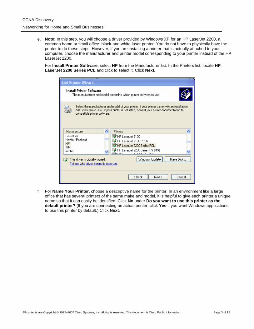
e. Note: In this step, you will choose a driver provided by Windows XP for an HP LaserJet 2200, a common home or small office, black-and-white laser printer. You do not have to physically have the printer to do these steps. However, if you are installing a printer that is actually attached to your computer, choose the manufacturer and printer model corresponding to your printer instead of the HP LaserJet 2200.
For Install Printer Software, select HP from the Manufacturer list. In the Printers list, locate HP LaserJet 2200 Series PCL and click to select it. Click Next.
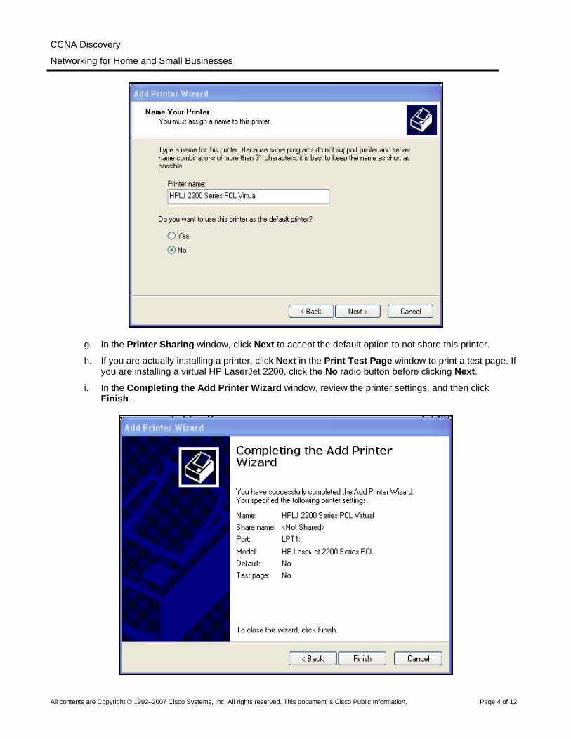
f. For Name Your Printer, choose a descriptive name for the printer. In an environment like a large office that has several printers of the same make and model, it is helpful to give each printer a unique name so that it can easily be identified. Click No under Do you want to use this printer as the default printer? (If you are connecting an actual printer, click Yes if you want Windows applications to use this printer by default.) Click Next.
CCNA Discovery
Networking for Home and Small Businesses
All contents are Copyright © 1992–2007 Cisco Systems, Inc. All rights reserved. This document is Cisco Public Information. Page 4 of 12
g. In the Printer Sharing window, click Next to accept the default option to not share this printer.
h. If you are actually installing a printer, click Next in the Print Test Page window to print a test page. If you are installing a virtual HP LaserJet 2200, click the No radio button before clicking Next.
i. In the Completing the Add Printer Wizard window, review the printer settings, and then click Finish.
CCNA Discovery
Networking for Home and Small Businesses
All contents are Copyright © 1992–2007 Cisco Systems, Inc. All rights reserved. This document is Cisco Public Information. Page 5 of 12
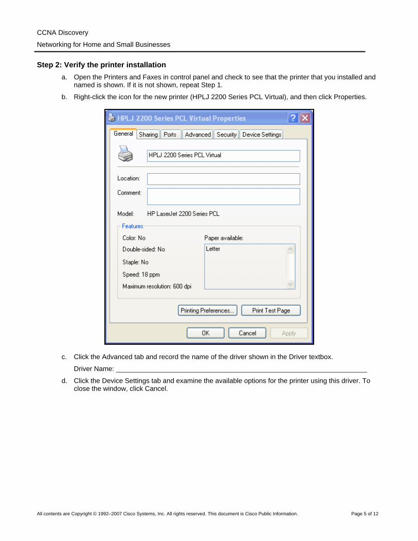
Step 2: Verify the printer installation a. Open the Printers and Faxes in control panel and check to see that the printer that you installed and
named is shown. If it is not shown, repeat Step 1.
b. Right-click the icon for the new printer (HPLJ 2200 Series PCL Virtual), and then click Properties.
c. Click the Advanced tab and record the name of the driver shown in the Driver textbox.
Driver Name: __________________________________________________________________
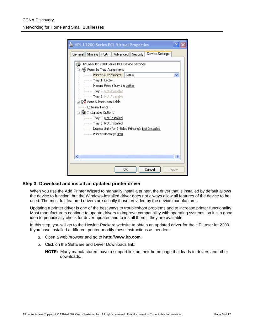
d. Click the Device Settings tab and examine the available options for the printer using this driver. To close the window, click Cancel.
CCNA Discovery
Networking for Home and Small Businesses
All contents are Copyright © 1992–2007 Cisco Systems, Inc. All rights reserved. This document is Cisco Public Information. Page 6 of 12
Step 3: Download and install an updated printer driver When you use the Add Printer Wizard to manually install a printer, the driver that is installed by default allows the device to function, but the Windows-installed driver does not always allow all features of the device to be used. The most full-featured drivers are usually those provided by the device manufacturer.
Updating a printer driver is one of the best ways to troubleshoot problems and to increase printer functionality. Most manufacturers continue to update drivers to improve compatibility with operating systems, so it is a good idea to periodically check for driver updates and to install them if they are available.
In this step, you will go to the Hewlett-Packard website to obtain an updated driver for the HP LaserJet 2200. If you have installed a different printer, modify these instructions as needed.
a. Open a web browser and go to http://www.hp.com.
b. Click on the Software and Driver Downloads link.
NOTE: Many manufacturers have a support link on their home page that leads to drivers and other downloads.
CCNA Discovery
Networking for Home and Small Businesses
All contents are Copyright © 1992–2007 Cisco Systems, Inc. All rights reserved. This document is Cisco Public Information. Page 7 of 12
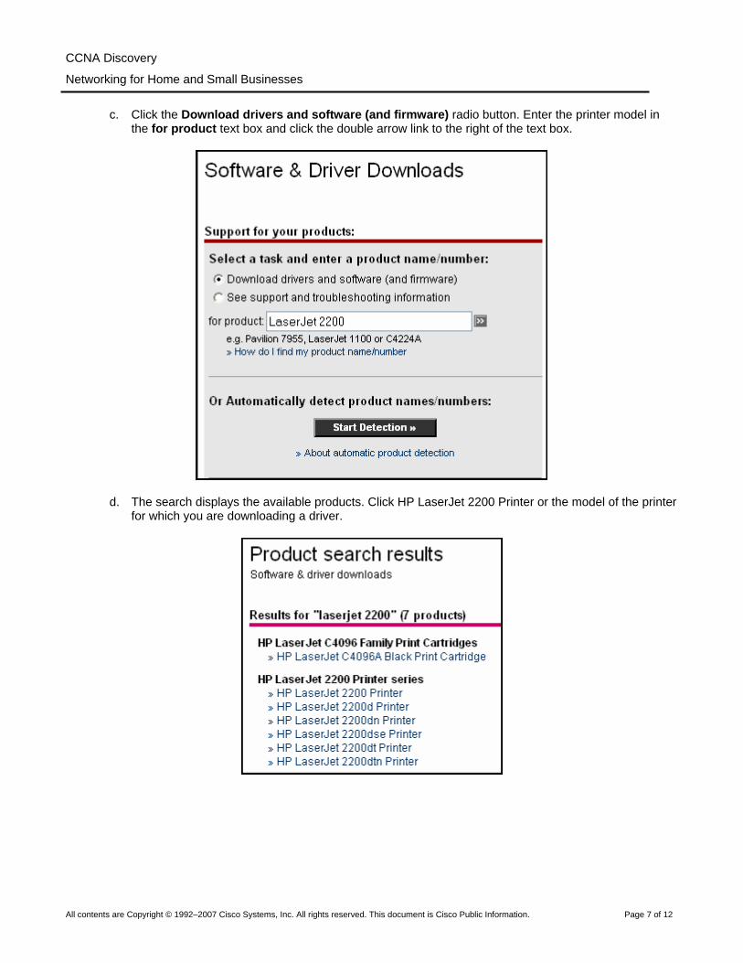
c. Click the Download drivers and software (and firmware) radio button. Enter the printer model in the for product text box and click the double arrow link to the right of the text box.
d. The search displays the available products. Click HP LaserJet 2200 Printer or the model of the printer for which you are downloading a driver.
CCNA Discovery
Networking for Home and Small Businesses
All contents are Copyright © 1992–2007 Cisco Systems, Inc. All rights reserved. This document is Cisco Public Information. Page 8 of 12
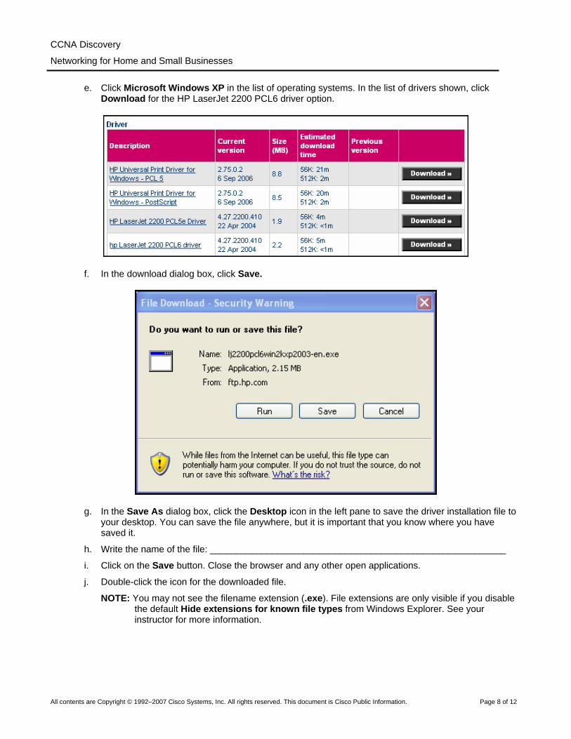
e. Click Microsoft Windows XP in the list of operating systems. In the list of drivers shown, click Download for the HP LaserJet 2200 PCL6 driver option.
f. In the download dialog box, click Save.
g. In the Save As dialog box, click the Desktop icon in the left pane to save the driver installation file to your desktop. You can save the file anywhere, but it is important that you know where you have saved it.
h. Write the name of the file: _________________________________________________________
i. Click on the Save button. Close the browser and any other open applications.
j. Double-click the icon for the downloaded file.
NOTE: You may not see the filename extension (.exe). File extensions are only visible if you disable the default Hide extensions for known file types from Windows Explorer. See your instructor for more information.

CCNA Discovery
Networking for Home and Small Businesses
All contents are Copyright © 1992–2007 Cisco Systems, Inc. All rights reserved. This document is Cisco Public Information. Page 9 of 12
k. When prompted, click Run. In the dialog box, click the second radio button and then Next to unpack the files to c:\lj2200. Click Finish.
l. Repeat Steps 2a and 2b to open the Properties page of the new printer. Click the Advanced tab. Click the New Drive button, and then click Next to begin the Add Printer Driver Wizard.
m. Click Have Disk in the Printer Driver Selection window.

CCNA Discovery
Networking for Home and Small Businesses
All contents are Copyright © 1992–2007 Cisco Systems, Inc. All rights reserved. This document is Cisco Public Information. Page 10 of 12
n. In the Install From Disk window, click Browse and locate the folder created in Step 3 by navigating to My Computer > Local Disk C:\lj2200. Click Open and you return to the Install From Disk window. Click OK.
o. In the Printer Driver Selection window, select HP LaserJet 2200 Series PCL 6, and then click Next. Click Finish in the window that follows.
p. When the process is finished, return to the properties window of the printer and click the Apply button, and then click OK.

CCNA Discovery
Networking for Home and Small Businesses
All contents are Copyright © 1992–2007 Cisco Systems, Inc. All rights reserved. This document is Cisco Public Information. Page 11 of 12
Step 4: Verify the new driver installation In this step, you will compare the Windows default driver installed in the first step to the newly installed driver from the manufacturer website.
a. In the properties window of the new printer, verify that the Apply button is grayed out.
b. Click the Advanced tab. What is the name of the driver?
Driver Name: __________________________________________________________________
c. Click the Configure tab. The window for the HP LaserJet 2200 is shown in the figure.
d. Compare this tab to the Device Settings tab in Step 2d. What are the differences?
1
2
3
4
5
6

CCNA Discovery
Networking for Home and Small Businesses
All contents are Copyright © 1992–2007 Cisco Systems, Inc. All rights reserved. This document is Cisco Public Information. Page 12 of 12
e. Click on some of the other tabs in the properties window to compare the new and old drivers. Record some of the differences here.
1
2
3
All contents are Copyright © 1992–2007 Cisco Systems, Inc. All rights reserved. This document is Cisco Public Information. Page 1 of 3
Lab 2.3.3 Examining Operating System and Application Versions Objectives
• Determine the operating system (OS) version and revision. • Examine the method used for configuring Windows XP updates. • Determine the revision number of a particular application.
Background / Preparation It is important to keep operating systems and applications up-to-date to ensure stable operation and to address security vulnerabilities. These updates are called revisions, updates, patches, or hot fixes. There are three ways to update the Windows XP operating system: automatic updating, downloading patches automatically and manually determining when they are installed, or manually downloading and installing the patches.
This lab can be done individually, in pairs, or in teams. The following resources are required:
• Computer with Windows XP and an application such as Microsoft Word installed
Step 1: Determine the Windows XP version and revision number a. Click the Start button and select All Programs > Accessories > Windows Explorer.
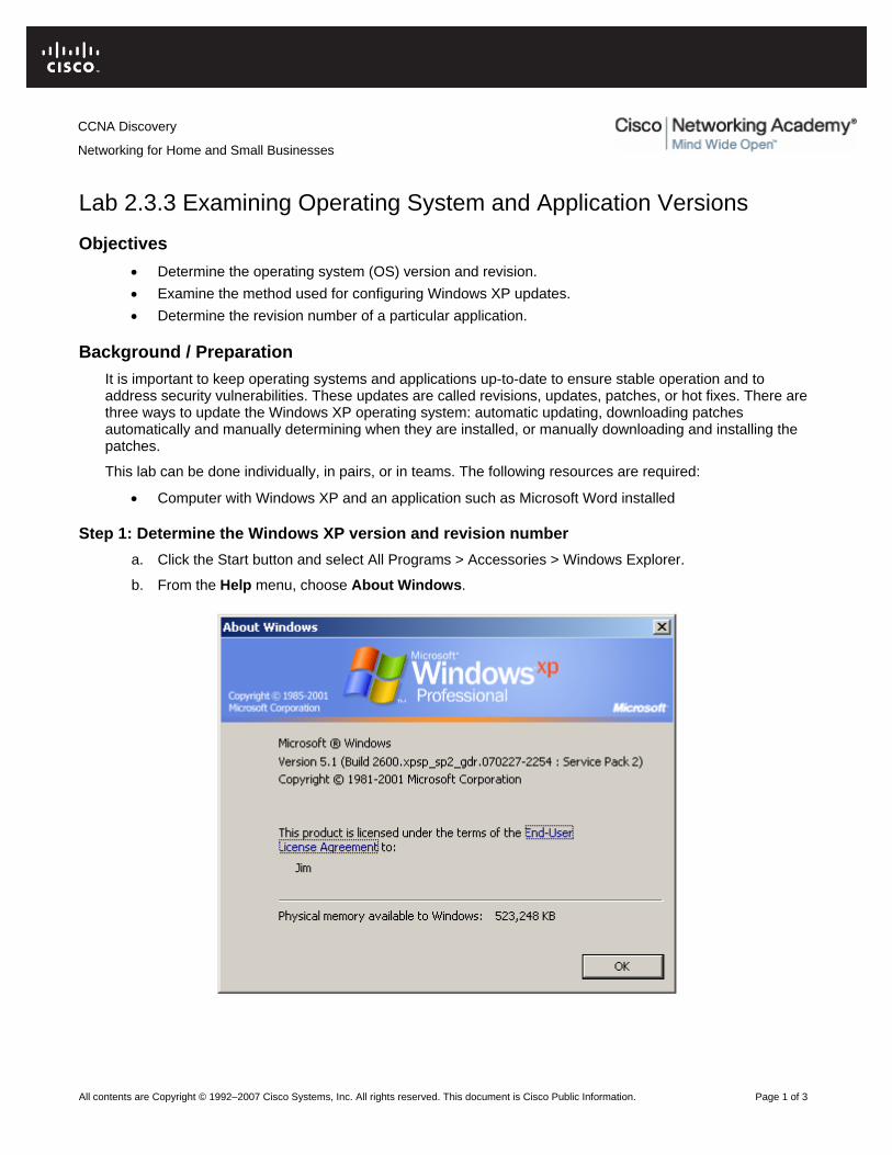
b. From the Help menu, choose About Windows.
CCNA Discovery
Networking for Home and Small Businesses
CCNA Discovery
Networking for Home and Small Businesses
All contents are Copyright © 1992–2007 Cisco Systems, Inc. All rights reserved. This document is Cisco Public Information. Page 2 of 3
c. Which version of Windows XP and service pack is installed on your computer? ________________________________________________________________________________
d. How much physical memory (RAM) is available to Windows XP?
________________________________________________________________________________
e. Why is memory important to an operating system? ________________________________________________________________________________
________________________________________________________________________________
________________________________________________________________________________
________________________________________________________________________________
f. Click on the End-user License Agreement link on the About Windows screen.
According to the license agreement, how many backup copies of Windows XP can you legally make? ________________________________________________________________________________
g. Close the end-user license agreement window. Close the About Windows window.
Step 2: Configure Windows XP for updates a. Click on the Start button and select the Control Panel option.
b. If the right window pane shows Pick a Category, select the Switch to Classic View link in the left pane. Double-click the Automatic Updates option.
c. Which four options are available for automatic updates? ___________________________________
________________________________________________________________________________
________________________________________________________________________________
d. Click on the How Does Automatic Updates Work? link. Expand the How Are Updates Downloaded? section by clicking on the + (plus sign) beside the option.
e. Based on the information presented, what happens if you are using your computer, updates are being downloaded, and you disconnect from the Internet? ________________________________________________________________________________
f. Expand the How Are Updates Installed? section.
Based on the output shown, what is the default time for when updates are installed? ________________________________________________________________________________
g. Close the How Does Automatic Updates Work? window and return to the Automatic Updates window.
h. What is the current setting for automatic updates, and why do you think the person who set up the computer chose this option?
________________________________________________________________________________
i. Close the Automatic Updates window.
j. Another way of configuring a system for automatic updates is through the System control panel. Click the Start button, click the Control Panel option, and double-click the System control panel icon. Click on the Automatic Updates tab.
k. Are the options the same as before? __________________________________________________
l. Close the System control panel.
Step 3: Determine an application version a. Open any Windows-based application such as Microsoft Word.
CCNA Discovery
Networking for Home and Small Businesses
All contents are Copyright © 1992–2007 Cisco Systems, Inc. All rights reserved. This document is Cisco Public Information. Page 3 of 3
b. From the application Help menu option, choose the About option.
c. What is the application version? ______________________________________________________
d. If this is a Microsoft application, there may be a System Info button. If there is a button, click on it. If there is no button, skip to the next step. Explore the different options available under System Info, including information related to your specific application. System Info provides similar information to that provided by winmsd.exe.
e. Click on the Help menu again. If there are double down arrows at the bottom of the menu, click them to show all the menu options. Some applications have a Check for Updates option. Does the application have this option? ________________________________________________________
f. Do you think that Internet access is required for an application that has a Check for Updates option? Why or why not? __________________________________________________________________
________________________________________________________________________________
g. Close the application.
Step 4: Reflection a. When is it important to get an update for an application or an operating system?
________________________________________________________________________________
________________________________________________________________________________
________________________________________________________________________________
b. List one instance when you might need to know which version of the operating system or application is being used. ____________________________________________________________________
________________________________________________________________________________
________________________________________________________________________________
All contents are Copyright © 1992–2007 Cisco Systems, Inc. All rights reserved. This document is Cisco Public Information. Page 1 of 7
Lab 3.1.5 Building a Peer-to-Peer Network Objectives
• Design and build a simple peer-to-peer network using a crossover cable supplied by the instructor. • Verify connectivity between the peers using the ping command.
Background / Preparation In this hands-on lab, you will plan and build a simple peer-to-peer network using two PCs and an Ethernet crossover cable.
The following resources are required:
• Two Window XP Professional PCs, each with an installed and functional Network Interface Card (NIC)
• An Ethernet crossover cable
Step 1: Diagram the network a. A network diagram is a map of the logical topology of the network. In the space below, sketch a
simple peer-to-peer network connecting two PCs. Label one PC with IP address 192.168.1.1 and the other PC with IP address 192.168.1.2. Use labels to indicate connecting media and any necessary network devices.
b. A simple network like the one you designed can use a hub or switch as a central connecting device, or the PCs may be directly connected. Which kind of cable is required for a direct Ethernet connection between the two PCs? _________________________________________________________
CCNA Discovery
Networking for Home and Small Businesses

CCNA Discovery
Networking for Home and Small Businesses
All contents are Copyright © 1992–2007 Cisco Systems, Inc. All rights reserved. This document is Cisco Public Information. Page 2 of 7
Step 2: Document the PCs a. Check the computer name settings for each PC and make adjustments as necessary. For each PC,
select Start and Control Panel. Double-click the System icon, then click the Computer Name tab. Write down the computer name that is displayed following Full computer name:
PC1 Name:
PC2 Name:
b. Check to see if the two PCs have the same name. If they do, change the name of one PC by clicking the Change button, typing a new name in the Computer name field, then clicking OK.
c. Click OK to close the System Properties window.
d. Why is it important that each PC on a network have a unique name?
____________________________________________________________________________
CCNA Discovery
Networking for Home and Small Businesses
All contents are Copyright © 1992–2007 Cisco Systems, Inc. All rights reserved. This document is Cisco Public Information. Page 3 of 7
Step 3: Connect the Ethernet cable a. Use the Ethernet crossover cable provided by the instructor. Plug one end of the cable into the
Ethernet NIC of PC1.
b. Plug the other end of the cable into the Ethernet NIC of PC2. As you insert the cable, you should hear a click which indicates that the cable connector is properly inserted into the port.
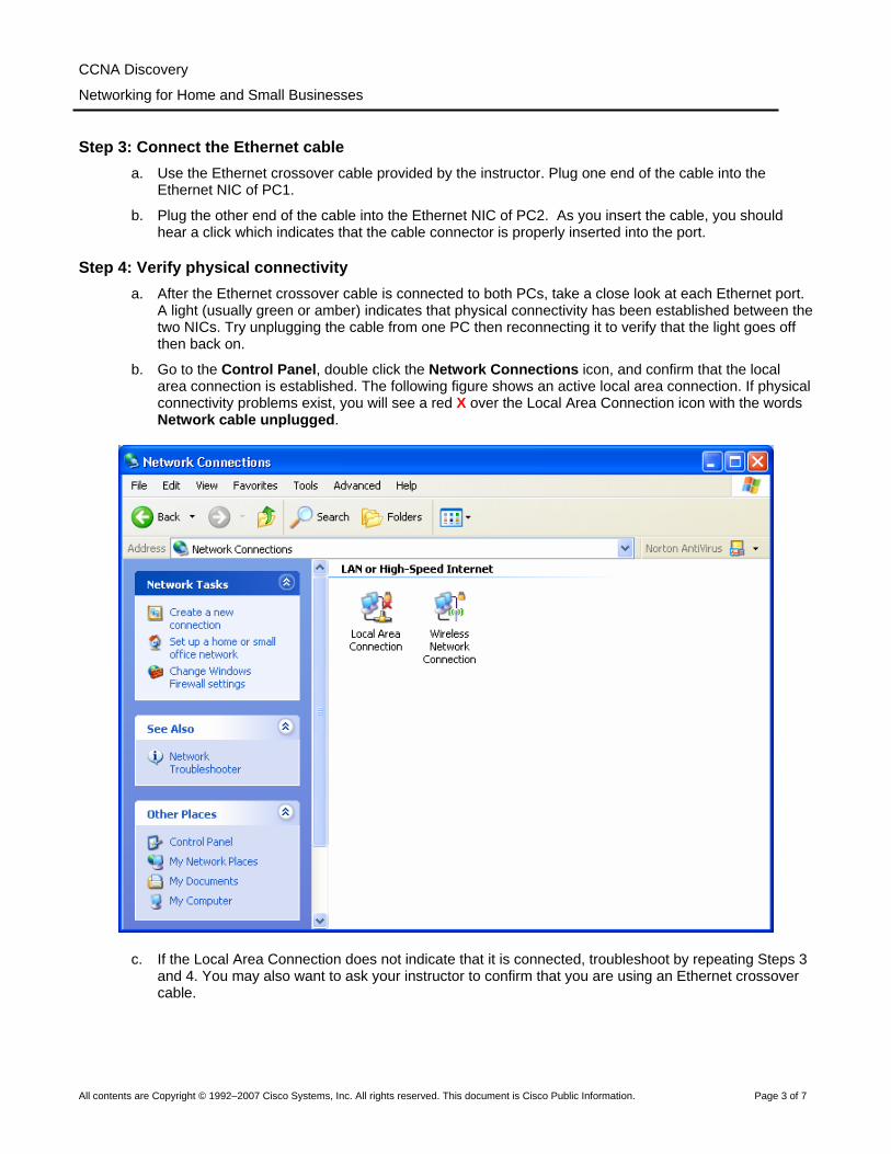
Step 4: Verify physical connectivity a. After the Ethernet crossover cable is connected to both PCs, take a close look at each Ethernet port.
A light (usually green or amber) indicates that physical connectivity has been established between the two NICs. Try unplugging the cable from one PC then reconnecting it to verify that the light goes off then back on.
b. Go to the Control Panel, double click the Network Connections icon, and confirm that the local area connection is established. The following figure shows an active local area connection. If physical connectivity problems exist, you will see a red X over the Local Area Connection icon with the words Network cable unplugged.
c. If the Local Area Connection does not indicate that it is connected, troubleshoot by repeating Steps 3 and 4. You may also want to ask your instructor to confirm that you are using an Ethernet crossover cable.

CCNA Discovery
Networking for Home and Small Businesses
All contents are Copyright © 1992–2007 Cisco Systems, Inc. All rights reserved. This document is Cisco Public Information. Page 4 of 7
Step 5: Configure IP settings a. Configure the logical addresses for the two PCs so that they are able to communicate using TCP/IP.
On one of the PCs, go to the Control Panel, double click the Network Connections icon, and then right click the connected Local Area Connection icon. Choose Properties from the pull-down menu.
b. Using the scroll bar in the Local Area Connection Properties window, scroll down to highlight Internet Protocol (TCP/IP). Click the Properties button.
CCNA Discovery
Networking for Home and Small Businesses
All contents are Copyright © 1992–2007 Cisco Systems, Inc. All rights reserved. This document is Cisco Public Information. Page 5 of 7
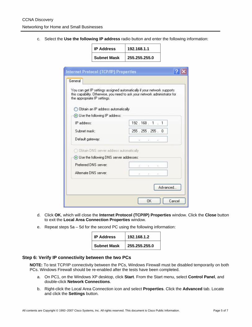
c. Select the Use the following IP address radio button and enter the following information:
IP Address 192.168.1.1
Subnet Mask 255.255.255.0
d. Click OK, which will close the Internet Protocol (TCP/IP) Properties window. Click the Close button to exit the Local Area Connection Properties window.
e. Repeat steps 5a – 5d for the second PC using the following information:
IP Address 192.168.1.2
Subnet Mask 255.255.255.0
Step 6: Verify IP connectivity between the two PCs NOTE: To test TCP/IP connectivity between the PCs, Windows Firewall must be disabled temporarily on both PCs. Windows Firewall should be re-enabled after the tests have been completed.
a. On PC1, on the Windows XP desktop, click Start. From the Start menu, select Control Panel, and double-click Network Connections.
b. Right-click the Local Area Connection icon and select Properties. Click the Advanced tab. Locate and click the Settings button.

CCNA Discovery
Networking for Home and Small Businesses
All contents are Copyright © 1992–2007 Cisco Systems, Inc. All rights reserved. This document is Cisco Public Information. Page 6 of 7
c. Make a note of whether the firewall settings are ENABLED (ON) for the Ethernet port or DISABLED (OFF) for the Ethernet port. ____________________________________________________
d. If the firewall settings are enabled, click the Off (not recommended) radio button to disable the firewall. The setting will be re-enabled in a later step. Click OK in this dialog box and the following to apply this setting.
e. Now that the two PCs are physically connected and configured correctly with IP addresses, we need to make sure they communicate with each other. The ping command is a simple way to accomplish this task. The ping command is included with the Windows XP operating system.
f. On PC1, go to Start, then Run. Type cmd, and then click OK. A Windows command prompt window will appear as shown in the figure below.
g. At the > prompt, type ping 192.168.1.2 and press Enter. A successful ping will verify the IP connectivity. It should produce results similar to those shown in here.
h. Repeat Steps 6a-6c on the second PC. The second PC will ping 192.168.1.1.
i. Close the Windows command prompt window on both PCs.

CCNA Discovery
Networking for Home and Small Businesses
All contents are Copyright © 1992–2007 Cisco Systems, Inc. All rights reserved. This document is Cisco Public Information. Page 7 of 7
Step 7: Verify connectivity using My Network Places a. A PC can share its resources with other PCs on the network. PCs with shared resources should be
visible through My Network Places. On PC1, go to Start, click My Network Places, and then click View workgroup computers in the left panel.
b. Do you see an icon for the other PC in your peer-to-peer network? _______________________
c. What is the name of the other PC? ________________________________________________
d. Is it the same name you recorded in Step 2? _________________________________________
e. Perform Step 7a on the second PC.
f. Close any open windows.
Step 8: (Optional – Use only if the Firewall was originally ENABLED) Re-enable the firewall a. If you disabled the Windows Firewall in Step 6, click Start, select Control Panel, and open the
Network Connections control panel.
b. Right-click the Ethernet network connection icon and select Properties. Click the Advanced tab. Locate and click Settings.
c. If the firewall settings are disabled (and they were enabled before this lab began), click the On radio button to enable the firewall. Click OK in this dialog box and the following one to apply this setting.

All contents are Copyright © 1992–2007 Cisco Systems, Inc. All rights reserved. This document is Cisco Public Information. Page 1 of 5
Lab 3.3.3 Determine the MAC Address of a Host
Objective
• Determine the MAC address of a Windows XP computer on an Ethernet network using the ipconfig /all command.
• Access to the Run command.
Background/Preparation
Every computer on an Ethernet local network has a Media Access Control (MAC) address that is burned into the Network Interface Card (NIC). Computer MAC addresses are usually displayed as 6 sets of two hexadecimal numbers separated by dashes or colons. (example: 15-EF-A3-45-9B-57). The ipconfig /all command displays the computer MAC address. You may work individually or in teams.
The following resources are required:
• Windows XP workstation with at least one Ethernet network interface card (NIC)
CCNA Discovery
Networking for Home and Small Businesses

CCNA Discovery
Networking for Home and Small Businesses
All contents are Copyright © 1992–2007 Cisco Systems, Inc. All rights reserved. This document is Cisco Public Information. Page 2 of 5
Step 1: Open a Windows command prompt window
a. From the Windows XP desktop, click Start then Run.
b. Type cmd in the Run dialogue box then click OK.

CCNA Discovery
Networking for Home and Small Businesses
All contents are Copyright © 1992–2007 Cisco Systems, Inc. All rights reserved. This document is Cisco Public Information. Page 3 of 5
c. A Windows command prompt window opens.
Step 2: Use the ipconfig /all command
a. Enter the ipconfig /all command at the command prompt.
CCNA Discovery
Networking for Home and Small Businesses
All contents are Copyright © 1992–2007 Cisco Systems, Inc. All rights reserved. This document is Cisco Public Information. Page 4 of 5
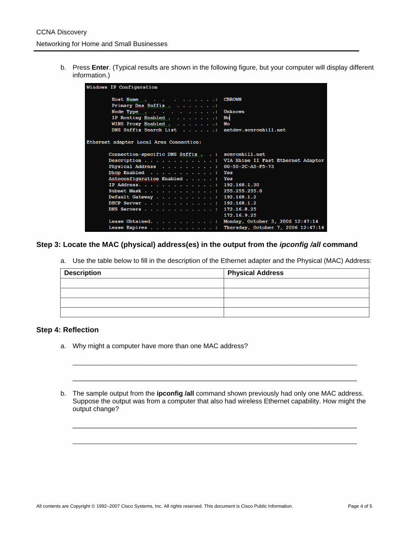
b. Press Enter. (Typical results are shown in the following figure, but your computer will display different information.)
Step 3: Locate the MAC (physical) address(es) in the output from the ipconfig /all command
a. Use the table below to fill in the description of the Ethernet adapter and the Physical (MAC) Address:
Description Physical Address
Step 4: Reflection
a. Why might a computer have more than one MAC address?
____________________________________________________________________________
____________________________________________________________________________
b. The sample output from the ipconfig /all command shown previously had only one MAC address. Suppose the output was from a computer that also had wireless Ethernet capability. How might the output change?
____________________________________________________________________________
____________________________________________________________________________

CCNA Discovery
Networking for Home and Small Businesses
All contents are Copyright © 1992–2007 Cisco Systems, Inc. All rights reserved. This document is Cisco Public Information. Page 5 of 5
c. Try disconnecting the cable(s) to your network adapter(s) and use the ipconfig /all command again. What changes do you see? Does the MAC address still display? Will the MAC address ever change?
____________________________________________________________________________
____________________________________________________________________________
____________________________________________________________________________
d. What are other names for the MAC address?
____________________________________________________________________________
____________________________________________________________________________
All contents are Copyright © 1992–2007 Cisco Systems, Inc. All rights reserved. This document is Cisco Public Information. Page 1 of 2
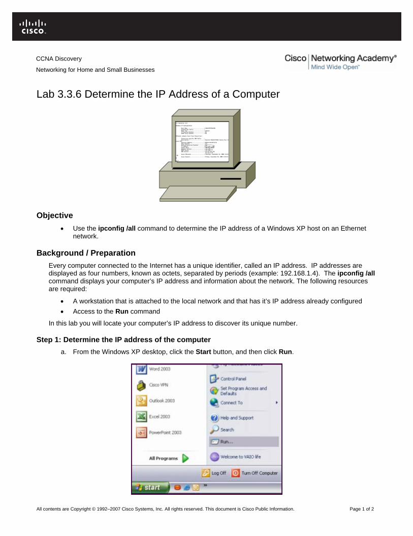
Lab 3.3.6 Determine the IP Address of a Computer
Objective
• Use the ipconfig /all command to determine the IP address of a Windows XP host on an Ethernet network.
Background / Preparation Every computer connected to the Internet has a unique identifier, called an IP address. IP addresses are displayed as four numbers, known as octets, separated by periods (example: 192.168.1.4). The ipconfig /all command displays your computer’s IP address and information about the network. The following resources are required:
• A workstation that is attached to the local network and that has it’s IP address already configured • Access to the Run command
In this lab you will locate your computer’s IP address to discover its unique number.
Step 1: Determine the IP address of the computer a. From the Windows XP desktop, click the Start button, and then click Run.
CCNA Discovery
Networking for Home and Small Businesses

CCNA Discovery
Networking for Home and Small Businesses
All contents are Copyright © 1992–2007 Cisco Systems, Inc. All rights reserved. This document is Cisco Public Information. Page 2 of 2
b. In the Run dialog box, type cmd then click the OK button.
c. At the command prompt, type ipconfig /all and press Enter.
d. The ipconfig /all command then displays a list of information about your computer’s IP configuration.
An example is shown in the following figure. The information displayed for your computer will be different.
e. Locate the IP address and record the finding.
IP address _____________________________________
f. Why is it important that a computer get an IP address? ________________________________
____________________________________________________________________________

CCNA Discovery
Networking for Home and Small Businesses
Lab 3.5.2 IP Addresses and Network Communication
Objectives • Build a simple peer-to-peer network and verify physical connectivity. • Assign various IP addresses to hosts and observe the effects on network communication
Background / Preparation In this lab, you will build a simple peer-to-peer network using two PCs and an Ethernet crossover cable. You will assign various compatible and non-compatible IP addresses to the hosts and determine the effects on their ability to communicate.
The following resources are required:
NOTE: You may use the small peer-to-peer network that was built in Lab 3.1.5
• Two Windows XP Professional PCs, each with an installed and functional Network Interface Card (NIC)
• An Ethernet cross-over cable to connect the PCs (provided by instructor) • (Optional lab setup) A hub or switch and two straight-through cables to connect the PCs (provided by
instructor)
Step 1: Connect the PCs to create a peer-to-peer network a. Obtain an Ethernet crossover cable provided by the instructor to connect the two PCs.
NOTE: (optional lab setup) The PCs may be connected to a hub (or switch) using two straight-through cables. The following instructions assume you are using a crossover cable.
b. Plug one end of the cable into the Ethernet NIC of PC1. Plug the other end of the cable into the Ethernet NIC of PC2. As you insert the cable, you should hear a click which indicates that the cable connector is properly inserted into the port.
Step 2: Verify physical connectivity a. After the Ethernet crossover cable is connected to both PCs, take a close look at each Ethernet port.
A link light (usually green or amber) indicates that physical connectivity has been established between the two NICs. Try unplugging the cable from one PC then reconnecting it to verify that the light goes off then back on.
All contents are Copyright © 1992–2007 Cisco Systems, Inc. All rights reserved. This document is Cisco Public Information. Page 1 of 6

CCNA Discovery
Networking for Home and Small Businesses
b. Go to the Control Panel, double click the Network Connections icon, and confirm that the local
area connection is established. The following figure shows an active local area connection. If physical connectivity problems exist, you will see a red X over the Local Area Connection icon with the words Network cable unplugged.
c. If the Local Area Connection does not indicate that it is connected, troubleshoot by repeating Steps 1 and 2. You may also want to ask your instructor to confirm that you are using an Ethernet crossover cable.
Step 3: Configure IP settings for the two PCs a. Configure the logical IP addresses for the two PCs so that they are able to communicate using
TCP/IP. On PC1, go to the Control Panel, double click the Network Connections icon, and then right click the connected Local Area Connection icon. Choose Properties from the pull-down menu.
All contents are Copyright © 1992–2007 Cisco Systems, Inc. All rights reserved. This document is Cisco Public Information. Page 2 of 6
CCNA Discovery
Networking for Home and Small Businesses
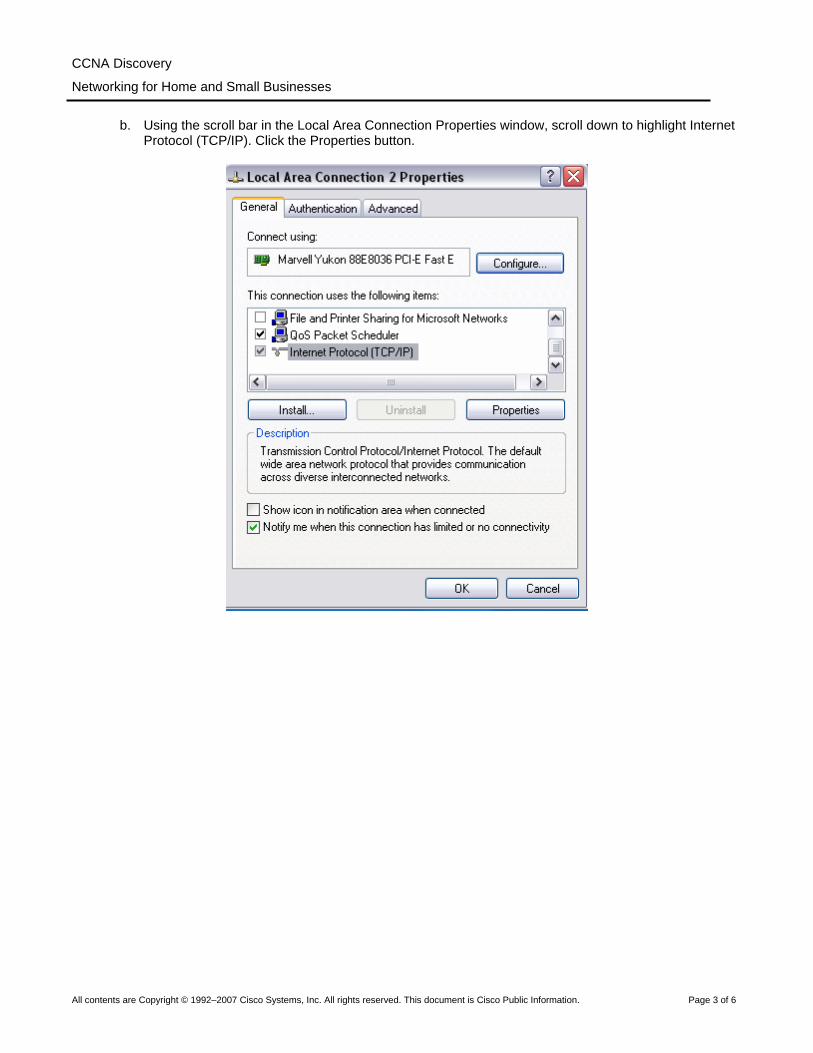
b. Using the scroll bar in the Local Area Connection Properties window, scroll down to highlight Internet
Protocol (TCP/IP). Click the Properties button.
All contents are Copyright © 1992–2007 Cisco Systems, Inc. All rights reserved. This document is Cisco Public Information. Page 3 of 6
CCNA Discovery
Networking for Home and Small Businesses
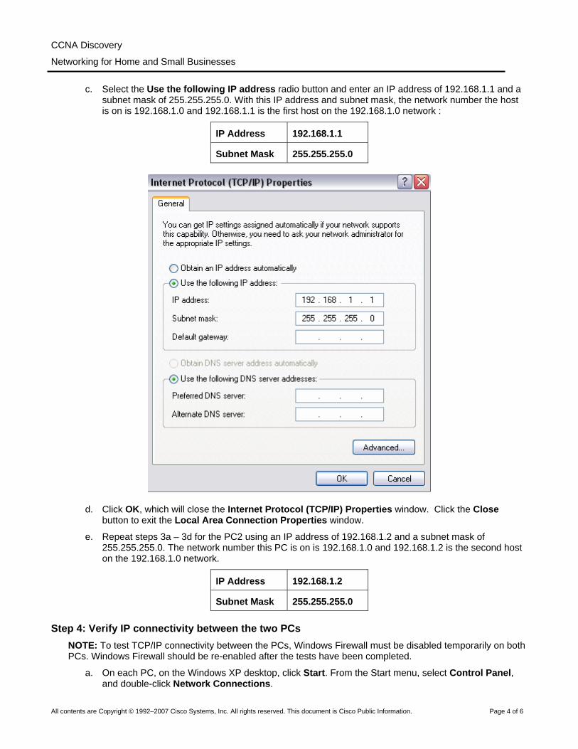
c. Select the Use the following IP address radio button and enter an IP address of 192.168.1.1 and a
subnet mask of 255.255.255.0. With this IP address and subnet mask, the network number the host is on is 192.168.1.0 and 192.168.1.1 is the first host on the 192.168.1.0 network :
IP Address 192.168.1.1
Subnet Mask 255.255.255.0
d. Click OK, which will close the Internet Protocol (TCP/IP) Properties window. Click the Close button to exit the Local Area Connection Properties window.
e. Repeat steps 3a – 3d for the PC2 using an IP address of 192.168.1.2 and a subnet mask of 255.255.255.0. The network number this PC is on is 192.168.1.0 and 192.168.1.2 is the second host on the 192.168.1.0 network.
IP Address 192.168.1.2
Subnet Mask 255.255.255.0
Step 4: Verify IP connectivity between the two PCs NOTE: To test TCP/IP connectivity between the PCs, Windows Firewall must be disabled temporarily on both PCs. Windows Firewall should be re-enabled after the tests have been completed.
a. On each PC, on the Windows XP desktop, click Start. From the Start menu, select Control Panel, and double-click Network Connections.
All contents are Copyright © 1992–2007 Cisco Systems, Inc. All rights reserved. This document is Cisco Public Information. Page 4 of 6

CCNA Discovery
Networking for Home and Small Businesses
b. Right-click the Local Area Connection icon and select Properties. Click the Advanced tab. Locate
and click the Settings button.
c. Make a note of whether the firewall settings are ENABLED (ON) for the Ethernet port or DISABLED (OFF) for the Ethernet port. _____________________________________________________
d. If the firewall settings are enabled, click the Off (not recommended) radio button to disable the firewall. The setting will be re-enabled in a later step. Click OK in this dialog box and the following to apply this setting. Repeat Steps 4a-4d on the second PC.
e. Now that the two PCs are physically connected and configured correctly with IP addresses, we need to make sure they communicate with each other. The ping command is a simple way to accomplish this task. The ping command is included with the Windows XP operating system.
f. On PC1, go to Start, then Run. Type cmd, and then click OK. A Window command prompt window will appear as shown in the following figure.
g. At the > prompt, type ping 192.168.1.2 and press Enter. A successful ping will verify the IP connectivity. It should produce results similar to those shown in the figure that follows.
h. Repeat this procedure for PC2 but ping 192.168.1.1.
i. Close the Windows command prompt window on both PCs.
Step 5: Change IP address for PC2 a. On PC2, go to the Control Panel, double click the Network Connections icon, and then right click the
connected Local Area Connection icon. Choose Properties from the pull-down menu.
b. Using the scroll bar in the Local Area Connection Properties window, scroll down to highlight Internet Protocol (TCP/IP). Click the Properties button.
c. Change the logical IP address for PC2 from 192.168.1.2 to 192.168.2.2 and leave the subnet mask set to 255.255.255.0. On what network is PC2 now? _________________________________
d. Click OK, which will close the Internet Protocol (TCP/IP) Properties window. Click the Close button to exit the Local Area Connection Properties window.
e. Refer back to Step 3c. On what network is PC1? ____________________________________
f. The two PCs are still on the same physical Ethernet network. Are they on the same logical IP network? _____________________
All contents are Copyright © 1992–2007 Cisco Systems, Inc. All rights reserved. This document is Cisco Public Information. Page 5 of 6
CCNA Discovery
Networking for Home and Small Businesses
Step 6: Test network connectivity between the 2 PCs
a. On PC1, go to Start, then Run. Type cmd, and then click OK. A Window command prompt window will appear.
b. At the > prompt, type ping 192.168.2.2 and press Enter. Was it successful? _________________
Why or why not? _________________________________________________________________
c. What type of networking device would allow the PCs to communicate? ______________________
Step 7: Change IP address for PC1 a. Using the procedure previously described, change the logical IP address for PC1 from 192.168.1.1 to
192.168.2.99 and leave the subnet mask set to 255.255.255.0. On what network is PC1 now? _______________________________________________________________________________
b. Click OK, which will close the Internet Protocol (TCP/IP) Properties window. Click the Close button to exit the Local Area Connection Properties window.
c. The two PCs are still on the same physical Ethernet network. Are they on the same logical IP network now? ___________________________________________________________________________
Step 8: Test network connectivity between the 2 PCs a. On PC2, go to Start, then Run. Type cmd, and then click OK. A Window command prompt window
will appear.
b. At the > prompt, type ping 192.168.2.99 and press Enter. Was it successful? _________________
Why or why not? __________________________________________________________________
Step 9: (Optional – Use only if the Firewall was originally ENABLED) Re-enable the firewall a. If you disabled the Windows Firewall in Step 4, click Start, select Control Panel, and click Network
Connections.
b. Right-click the Ethernet network connection icon and select Properties. Click the Advanced tab. Locate and click Settings.
c. If the firewall settings are disabled (and they were enabled before this lab began), click the On radio button to enable the firewall. Click OK in this dialog box and the following one to apply this setting.
All contents are Copyright © 1992–2007 Cisco Systems, Inc. All rights reserved. This document is Cisco Public Information. Page 6 of 6
All contents are Copyright © 1992–2007 Cisco Systems, Inc. All rights reserved. This document is Cisco Public Information. Page 1 of 9
Lab 3.6.4 Connect and Configure Hosts Objectives
• Connect a PC to a router using a straight-through cable. • Configure the PC with an appropriate IP address. • Configure the PC with a NetBIOS computer name. • Verify the PC configuration using Windows XP and through a command prompt.
Background / Preparation In order for the PC to participate in the local network and the Internet, it must be connected to a network device. The following resources will be required:
• Linksys Model WRT300N wireless router or equivalent SOHO router • Two computers with Ethernet NICs and Windows XP Professional installed on both • Two straight-through cables
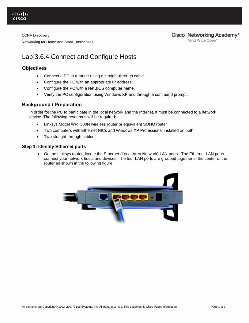
Step 1: Identify Ethernet ports a. On the Linksys router, locate the Ethernet (Local Area Network) LAN ports. The Ethernet LAN ports
connect your network hosts and devices. The four LAN ports are grouped together in the center of the router as shown in the following figure.
CCNA Discovery
Networking for Home and Small Businesses
CCNA Discovery
Networking for Home and Small Businesses
All contents are Copyright © 1992–2007 Cisco Systems, Inc. All rights reserved. This document is Cisco Public Information. Page 2 of 9
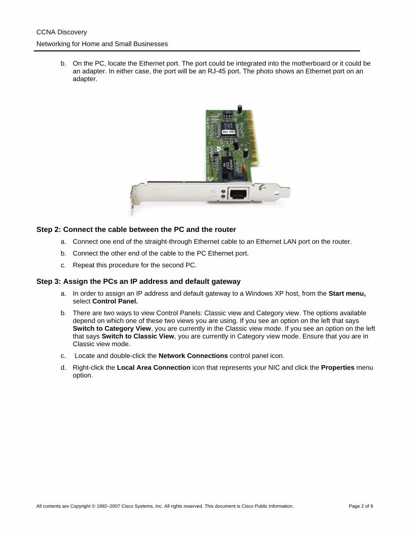
b. On the PC, locate the Ethernet port. The port could be integrated into the motherboard or it could be an adapter. In either case, the port will be an RJ-45 port. The photo shows an Ethernet port on an adapter.
Step 2: Connect the cable between the PC and the router a. Connect one end of the straight-through Ethernet cable to an Ethernet LAN port on the router.
b. Connect the other end of the cable to the PC Ethernet port.
c. Repeat this procedure for the second PC.
Step 3: Assign the PCs an IP address and default gateway a. In order to assign an IP address and default gateway to a Windows XP host, from the Start menu,
select Control Panel.
b. There are two ways to view Control Panels: Classic view and Category view. The options available depend on which one of these two views you are using. If you see an option on the left that says Switch to Category View, you are currently in the Classic view mode. If you see an option on the left that says Switch to Classic View, you are currently in Category view mode. Ensure that you are in Classic view mode.
c. Locate and double-click the Network Connections control panel icon.
d. Right-click the Local Area Connection icon that represents your NIC and click the Properties menu option.

CCNA Discovery
Networking for Home and Small Businesses
All contents are Copyright © 1992–2007 Cisco Systems, Inc. All rights reserved. This document is Cisco Public Information. Page 3 of 9
e. In the middle window, scroll down until you see and can double-click the Internet Protocol (TCP/IP) option. The figure that follows shows this option.

CCNA Discovery
Networking for Home and Small Businesses
All contents are Copyright © 1992–2007 Cisco Systems, Inc. All rights reserved. This document is Cisco Public Information. Page 4 of 9
f. Click the Properties button and the Internet Protocol [TCP/IP] Properties window will appear.. Next, click the Use the following IP address button, which activates the IP address, Subnet mask, and Default gateway textboxes.
In the IP address field, enter 192.168.10.2. Configure the subnet mask to 255.255.255.0. Configure the default gateway to 192.168.10.1. The figure that follows shows these settings. (DNS server information is not necessary at this time, so the fields under Use the following DNS server addresses don’t need to be filled out.) When finished, click OK.
g. From the Internet Protocol [TCP/IP] Properties window, click OK to apply the changes. Be patient, since this step may take some time. After the changes are applied, you will be returned to the Network Connections window.
h. Since the two computers are on the same network, their IP addresses will be similar, their subnet masks will be identical, and their default gateways will be identical. Perform the same procedures on the second PC to assign an IP address, subnet mask, and default gateway using the following information:
IP address: 192.168.10.3
Subnet mask: 255.255.255.0
Default gateway: 192.168.10.1

CCNA Discovery
Networking for Home and Small Businesses
All contents are Copyright © 1992–2007 Cisco Systems, Inc. All rights reserved. This document is Cisco Public Information. Page 5 of 9
i. Why do you think the IP addresses are different, but the subnet masks and default gateways are the same? ______________________________________________________________________
____________________________________________________________________________
____________________________________________________________________________
Step 4: Verify the IP address configuration a. On the Windows XP desktop, click Start.
b. From the Start menu, Select the Run menu option.
c. In the Open: textbox, type cmd and press Enter. A command prompt appears. The figures that follow show this process.
d. In the command line prompt, type ipconfig /all. Verify that the IP address and the default gateway are the values that you entered in the earlier steps. If they are incorrect, repeat Steps 3 and 4.
e. Are the IP address, subnet mask, and default gateway correct for the first PC? _____________
f. Perform the same configuration check on the second PC. If the values are incorrect, repeat Steps 3 and 4.
g. Are the IP address, subnet mask, and default gateway correct for the second PC? ___________
CCNA Discovery
Networking for Home and Small Businesses
All contents are Copyright © 1992–2007 Cisco Systems, Inc. All rights reserved. This document is Cisco Public Information. Page 6 of 9
Step 5: Test connectivity between the two PCs NOTE: To test TCP/IP connectivity between the PCs, Windows Firewall must be disabled temporarily on both PCs. Windows Firewall should be re-enabled after the tests have been completed.
a. On PC1, on the Windows XP desktop, click Start. From the Start menu, select Control Panel, and double-click Network Connections.
b. Right-click the Local Area Connection icon and select Properties. Click the Advanced tab. Locate and click the Settings button.
c. Make a note of whether the firewall settings are ENABLED (ON) for the Ethernet port or DISABLED (OFF) for the Ethernet port. _______________________________________________________
d. If the firewall settings are enabled, click the Off (not recommended) radio button to disable the firewall. The setting will be re-enabled in a later step. Click OK in this dialog box and the following to apply this setting.
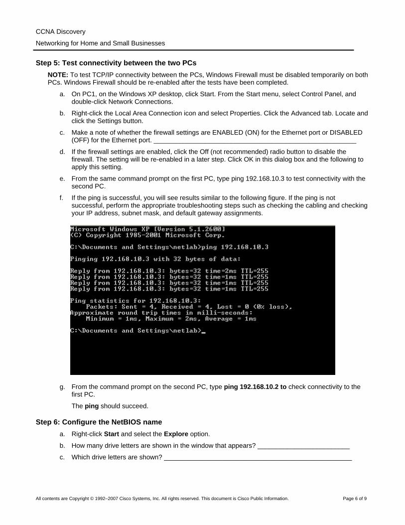
e. From the same command prompt on the first PC, type ping 192.168.10.3 to test connectivity with the second PC.
f. If the ping is successful, you will see results similar to the following figure. If the ping is not successful, perform the appropriate troubleshooting steps such as checking the cabling and checking your IP address, subnet mask, and default gateway assignments.
g. From the command prompt on the second PC, type ping 192.168.10.2 to check connectivity to the first PC.
The ping should succeed.
Step 6: Configure the NetBIOS name a. Right-click Start and select the Explore option.
b. How many drive letters are shown in the window that appears? _________________________
c. Which drive letters are shown? ___________________________________________________
CCNA Discovery
Networking for Home and Small Businesses
All contents are Copyright © 1992–2007 Cisco Systems, Inc. All rights reserved. This document is Cisco Public Information. Page 7 of 9
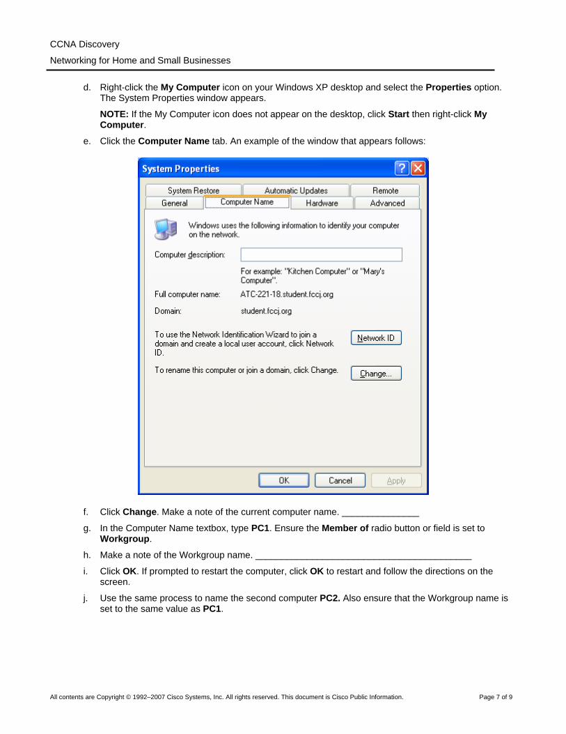
d. Right-click the My Computer icon on your Windows XP desktop and select the Properties option. The System Properties window appears.
NOTE: If the My Computer icon does not appear on the desktop, click Start then right-click My Computer.
e. Click the Computer Name tab. An example of the window that appears follows:
f. Click Change. Make a note of the current computer name. _______________
g. In the Computer Name textbox, type PC1. Ensure the Member of radio button or field is set to Workgroup.
h. Make a note of the Workgroup name. __________________________________________
i. Click OK. If prompted to restart the computer, click OK to restart and follow the directions on the screen.
j. Use the same process to name the second computer PC2. Also ensure that the Workgroup name is set to the same value as PC1.

CCNA Discovery
Networking for Home and Small Businesses
All contents are Copyright © 1992–2007 Cisco Systems, Inc. All rights reserved. This document is Cisco Public Information. Page 8 of 9
Step 7: Verify configuration a. To verify the new configuration, open a command prompt on each computer. If you forgot how, refer
to Steps 4a, b, and c.
b. Use the nbtstat command to view and gather information about remote computers. From the command prompt, type nbtstat and press Enter. Help for the command displays as shown:
The letters shown are options called switches that you can use with the nbtstat command.
a. On PC1, type nbtstat –n and press Enter to see the local NetBIOS name of PC1.
b. On PC2, type the same command to verify the NetBIOS name is set to PC2.
c. The nbtstat –a command can be used to look at a remote computer’s name table. Type nbtstat again from the command prompt. Notice in the output that when you use the –a switch, you have to put a space and then type a remote computer’s name (RemoteName).
From PC1, type nbtstat –a PC2 and press Enter. The nbtstat information for PC2 shows on PC1’s monitor.
What command would be used from the command prompt on PC2 to view information about PC1? ____________________________________________________________________________
d. From PC2, type the appropriate command to view PC1’s nbtstat information.
e. The nbtstat –A (notice that the switch is a capital A this time) can be used to view the same information using an IP address rather than a name. If you type nbtstat again, you can see that the command syntax tells us that we use –A followed by an IP address. The IP address is that of the remote computer.
From PC1, type nbtstat –A 192.168.10.3 to see the same information that was returned by the nbtstat –a PC2 command.
f. Write the command that would be typed on PC2 to view information about PC1, using the IP address of PC1 instead of the NetBIOS name. _____________________________________________
CCNA Discovery
Networking for Home and Small Businesses
All contents are Copyright © 1992–2007 Cisco Systems, Inc. All rights reserved. This document is Cisco Public Information. Page 9 of 9
g. From PC1, you can use the ping command to verify connectivity. However, instead of using an IP address, you can use the NetBIOS name. From the PC1 command prompt, type ping PC2 (notice the capitalization). The result should be successful.
h. From PC1, type ping pc2 (notice the capitalization).
i. Does the ping succeed using lower case letters? ______________________________________
j. You can use the nbtstat –r command to see NetBIOS names that have been resolved (they are known). From the PC1 and PC2 command prompt, type nbtstat –r to see that the remote computer is known using NetBIOS.
k. Close the command prompt window.
Step 8: (Optional – Use only if the Firewall was originally ENABLED) Re-enable the firewall a. If the answer to Step 5c was OFF or ENABLED on PC1, click Start, select Control Panel, and open
the Network Connections control panel.
b. Right-click the Ethernet network connection icon and select Properties. Click the Advanced tab. Locate and click Settings.
c. If the firewall settings are disabled (and they were enabled before this lab began), click the On radio button to disable the firewall. Click OK in this dialog box and the following one to apply this setting.
Step 9: Return IP Address and NetBIOS Name to original values a. Return to Step 3 to change the IP address back to the original.
b. Return to Step 6d to change the NetBIOS name back to the original.
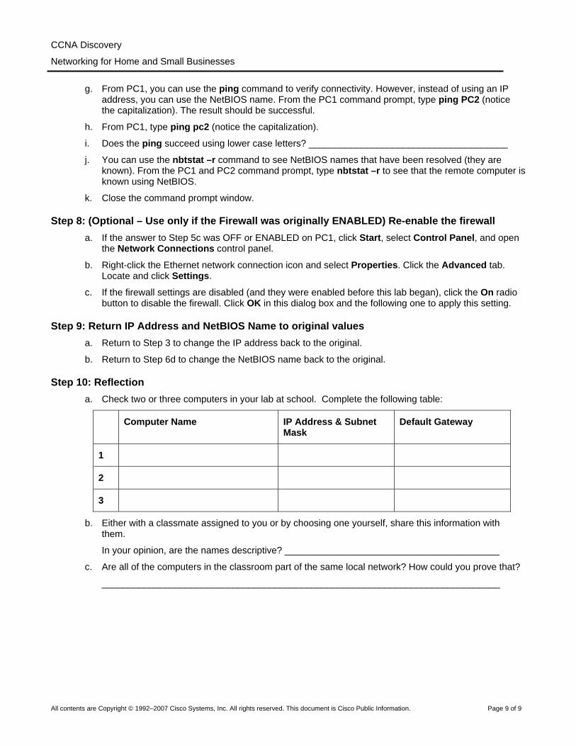
Step 10: Reflection a. Check two or three computers in your lab at school. Complete the following table:
Computer Name IP Address & Subnet Mask
Default Gateway
1
2
3
b. Either with a classmate assigned to you or by choosing one yourself, share this information with them.
In your opinion, are the names descriptive? _________________________________________
c. Are all of the computers in the classroom part of the same local network? How could you prove that?
____________________________________________________________________________
All contents are Copyright © 1992–2007 Cisco Systems, Inc. All rights reserved. This document is Cisco Public Information. Page 1 of 5
Lab 3.6.5 Sharing Resources Objectives Use Windows XP to complete the following tasks:
• Share files and folders. • Map network drives.
Background/Preparation One of the key benefits of having PCs networked together is that it provides access to be able to share information with other connected users. Whether it is a song, a proposal or your holiday pictures, there are many situations where you need to share data with friends or business colleagues.
Mapping drives, goes hand-in-hand with sharing folders because drive mappings provide quick access to commonly used folders. They also provide an easier way for users to navigate and find the files and/or folders they are looking for. Drive mappings redirect a local resource (drive letter) to a shared network resource (hard drive or folder on the network).
The following resources are required:
• Two configured Windows XP Professional workstations connected via a local network. Note: Use the previously configured network from lab activity 3.6.4.
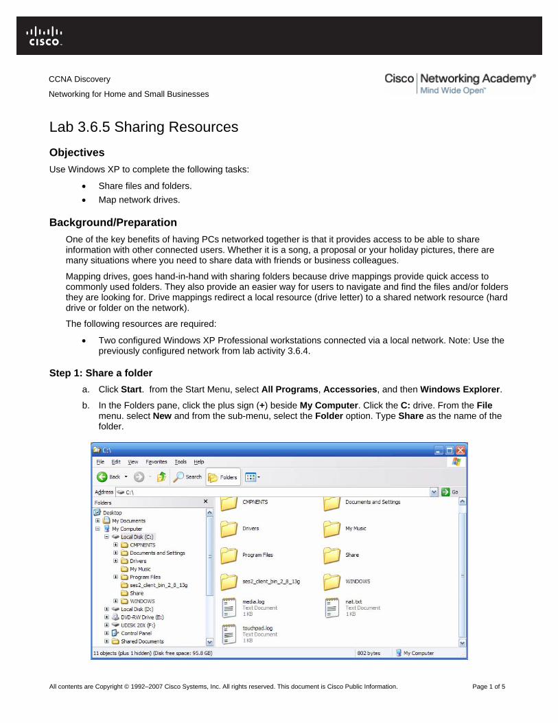
Step 1: Share a folder a. Click Start. from the Start Menu, select All Programs, Accessories, and then Windows Explorer.
b. In the Folders pane, click the plus sign (+) beside My Computer. Click the C: drive. From the File menu. select New and from the sub-menu, select the Folder option. Type Share as the name of the folder.
CCNA Discovery
Networking for Home and Small Businesses

CCNA Discovery
Networking for Home and Small Businesses
All contents are Copyright © 1992–2007 Cisco Systems, Inc. All rights reserved. This document is Cisco Public Information. Page 2 of 5
c. Right-click the new folder Share and choose Properties.
NOTE: The Sharing option is not available for the Documents and Settings, Program Files, and Windows system folders.
d. Select the Sharing tab. In the Share Properties dialog box, click the Share this folder radio button to share the folder with other users on your network. The default name for the shared folder is the same name as the original folder name.
NOTE: To change the name of the folder on the network, type a new name for the folder in the Share name text box. This will not change the name of the folder on your computer.
e. Click Apply and then OK.

CCNA Discovery
Networking for Home and Small Businesses
All contents are Copyright © 1992–2007 Cisco Systems, Inc. All rights reserved. This document is Cisco Public Information. Page 3 of 5
f. Create a text file using Notepad and save it to the Share folder. On the Windows XP desktop, click Start, select All Programs, Accessories, then Notepad.
In the Notepad application, type the message “Hello World!”.
From the File menu, select Save. In the File name field, type “Test message”. Click the icon with the folder and up arrow as shown in the following figure.
g. Double-click My Computer, then double-click drive C:. Locate and double-click the Share folder, then click Save.
h. Close the Notepad application.
i. Repeat Steps 1 – 5 for the second Windows XP Professional machine with the following exceptions:
Share name: Share2
Text file contents: Hello planet!
Text file name: Test Message 2
Step 2: Map network drives to provide quick and easy access to shared folders a. On the first Windows XP workstation, click Start, select All Programs, Accessories, and then
Windows Explorer.
b. In the Folders pane, click My Computer. From Tools Menu, select Map Network Drive….
c. In the Drive textbox, select an unused drive letter using the pulldown menu.
d. Question: What drive letter did you choose? ________________________________________

CCNA Discovery
Networking for Home and Small Businesses
All contents are Copyright © 1992–2007 Cisco Systems, Inc. All rights reserved. This document is Cisco Public Information. Page 4 of 5
e. In the Folder field, type the IP address of the remote PC and the name of the remote share using the format: \\ip_address\sharename
f. Click Finish.
A window will appear with the message Attempting to connect to \\192.168.10.3\share2. A window will open to display the contents of the shared folder called Share2 that has now been assigned a drive letter.
NOTE: The IP address can be replaced by the computer name.
g. Double-click the Test Message 2 text document. Add the words Techs rule to the document. From the File menu and select Save.
Question: What message is displayed? Why do you think this happened? _________________
____________________________________________________________________________
h. The files within a shared folder are automatically protected in the Windows XP Professional version. Click OK in the message box. Click Cancel, then click Close for the Test Message 2 document.
i. In the message box, click No to close the document without saving the changes.
j. Repeat procedures a-e under Step 2 to map a drive on the second Windows XP workstation. This drive should be mapped to the share you configured in Step 1.
Step 3: Verify work a. From the first Windows XP Professional machine, click Start, select All Programs, then
Accessories, and Windows Explorer.
b. Expand My Computer by clicking on the plus sign (+) beside the option.
c. The Windows Explorer list should display a drive with the drive letter label that you chose for the remote share.

CCNA Discovery
Networking for Home and Small Businesses
All contents are Copyright © 1992–2007 Cisco Systems, Inc. All rights reserved. This document is Cisco Public Information. Page 5 of 5
d. Repeat procedures a-c for the second Windows XP Professional machine.
If the drive letter appears on both computers, then the folders are shared and drives are mapped properly on both Windows XP workstations. You can perform the same steps on any folder. When a drive is properly mapped to shared folders, all files and folders within the shared folder will be accessible from the workstations.
Step 4: Reflection
a. What are some of the benefits of mapped drives and shared folders in a home or small office network?
____________________________________________________________________________
____________________________________________________________________________
____________________________________________________________________________
b. Which folders cannot be shared? Can you think of reasons why an operating system might not allow certain types of folders to be shared?
____________________________________________________________________________
____________________________________________________________________________
____________________________________________________________________________
c. A mapped drive provides a pointer to a network resource, but mapped drive letters are said to be locally significant only. What do you think is meant by locally significant?
____________________________________________________________________________
____________________________________________________________________________
____________________________________________________________________________

All contents are Copyright © 1992–2007 Cisco Systems, Inc. All rights reserved. This document is Cisco Public Information. Page 1 of 3
Lab 4.2.3 Tracing Internet Connectivity Objectives
• Use software that shows how data travels through the Internet. • Use the ping utility to test connectivity to a remote network. • Construct a visual map of connectivity from your network to a remote network.
Background / Preparation In order to perform this lab, Internet connectivity is required. On a PC, open a web browser to ensure connectivity exists before beginning this lab.
This lab has an optional first step of downloading and installing a free program that can be used to determine the path a packet takes through the Internet. This program may be free, but it also may be copyrighted. Also, it may be that you are not permitted on a campus computer to download and install software. Check with the instructor or student assistant if you are unsure.
The following resources will be required:
• Windows-based computer with Internet connectivity • Ability to download and install freeware software (optional) • Access to the Run command
Step 1: (Optional) Download and install a free program a. Open a search engine such as Google (www.google.com), Yahoo (www.yahoo.com), or Search
(http://search.com).
b. Which words do you think would give you the best result if you are searching for a visual program that allows you to trace how data (a packet) travels through the Internet? Write your search words.
____________________________________________________________________________
c. Type the words you chose in the Search field. Locate and download the software and install it. Normally, the website has a link to the download site or you can click the words “Download” or “Download Now”. When you download any freeware, remember the location on the hard drive, flash drive, or disk media where you saved the program. Write down where the download is saved.
____________________________________________________________________________
d. What is the name of the program you installed? ____________________________________
____________________________________________________________________________
Step 2: Locate web sites a. Using the search engine again, locate five businesses with a web server, which are located in a
country different from your own.
b. Write the names of the five business web sites.
____________________________________________________________________________
____________________________________________________________________________
____________________________________________________________________________
CCNA Discovery
Networking for Home and Small Businesses

CCNA Discovery
Networking for Home and Small Businesses
All contents are Copyright © 1992–2007 Cisco Systems, Inc. All rights reserved. This document is Cisco Public Information. Page 2 of 3
c. Using the search engine again, locate a business in your own country that has a web site that is accessible.
d. Write the URL of the web site. An example URL is www.cisco.com.
____________________________________________________________________________
Step 3: (Optional) Use downloaded visual trace route tool a. Using the software you have downloaded and installed, use the tool to determine the path which the
packet takes to reach one of the remote country destinations. Each tool normally allows you to type a URL. The program should either list or visually display the path taken by the packet.
b. How many hops does the packet take to get from your computer to the destination computer?
___________________________________________________________________________
c. If your tool also provides time information, write down how long it took for the packet to reach the first hop? _______________________________________________________________________
d. Use the tool to determine the path to another foreign country site.
e. How many hops does the packet take to get from your computer to the destination computer?
____________________________________________________________________________
f. Use the tool to determine the path to a web site in your own country.
g. Was the time it took to reach a web site in your own country shorter or longer? _____________
h. Try to think of an instance where the time it takes to reach a web server in your own country would be longer than it takes to reach another country’s web server? ____________________________
____________________________________________________________________________
____________________________________________________________________________
Step 4: Use the tracert command a. Click the Start button, click the Run option, type cmd, and press Enter. An alternate way to get to the
command prompt is to click Start > All Programs > Accessories > Command Prompt.
b. From the command prompt, type tracert and press Enter. Options that can be used with the tracert command are shown. Items shown in square brackets [ ] are optional. For example, the first option that can be used with the tracert command is –d. If someone was to type tracert –d www.cisco.com, then the command issued to the computer is to trace the route to www.cisco.com, but do not try to resolve IP addresses to names. The target_name parameter is mandatory (it does not have brackets around it) and it is replaced with the destination network. In the previous example of tracert –d www.cisco.com, www.cisco.com is the target_name.
c. Which tracert option would be used to designate that only 5 hops could be used to search for the device address on the destination network? _________________________________________
d. Write the full command that would be typed to trace a route to www.cisco.com and instruct the computer to not search for it after seven hops. _______________________________________
e. Using one of the remote country destination addresses (use the same address as the one you used with the visual tool if possible) use the tracert command to determine how many hops it takes to reach the remote web server. Write the number of hops and the destination.
____________________________________________________________________________
f. The tracert command uses Internet Control Message Protocol (ICMP) echo request messages to determine the path to the final destination. The path displayed is a list of IP addresses assigned to routers that connect to one another to form the path. The ICMP packets contain a value called a

CCNA Discovery
Networking for Home and Small Businesses
All contents are Copyright © 1992–2007 Cisco Systems, Inc. All rights reserved. This document is Cisco Public Information. Page 3 of 3
Time To Live (TTL). The TTL value is 30 by default on a Microsoft-based PC and each router through which the packet passes, decrements that value by 1 before sending the packet on to the next router in the path. When the TTL value reaches 0, the router that has the packet sends an ICMP time exceeded message back to the source.
The tracert command determines the path by sending the first ICMP echo request message with a TTL of 1 and then increases that TTL value by 1 until the target responds or the maximum number of hops is reached. The path is determined by examining the ICMP time exceed messages that are sent back by routers along the way and by the ICMP echo reply message that is returned from the destination. Routers that do not return the ICMP time exceed messages are shown by a row of asterisks (*).
How many hops does your tracert command show that the packet went through? ___________
Step 5: Use the pathping command a. A similar command that can be used on a Windows XP computer is pathping. This command
combines the abilities of the tracert command with the ping command. From the command prompt, use the pathping command to determine the IP addresses of the routers used to create the packet path to another foreign country address. An example of the pathping command used to trace the path to Cisco is pathping www.cisco.com.
b. How many hops did the pathping command display to your remote destination?
____________________________________________________________________________
c. When do you think that you would ever use a tool like pathping or tracert?
____________________________________________________________________________
Step 6: (Optional) Use the whois function a. Some of the freeware tools include an option to perform a whois function. Whois is a separate
program or integrated with a tool similar to tracert or pathping. It displays (and sometimes has a link) who owns the web link of either the destination URL (such as cisco.com) or any of the links along the path. Explore the freeware tool that you have downloaded and installed and determine if it has a whois function. If it does, use it to determine who owns the domain name of one of the previous destinations used.
b. Why would you want to use the whois function? _____________________________________
____________________________________________________________________________
____________________________________________________________________________
Step 7: Reflection With a classmate, compare all of the commands used in this lab. Describe the purpose and benefit of each one. Which do you think is the most useful command?
____________________________________________________________________________
____________________________________________________________________________
____________________________________________________________________________

All contents are Copyright © 1992–2007 Cisco Systems, Inc. All rights reserved. This document is Cisco Public Information. Page 1 of 5
Lab 4.5.3 Building Straight-Through and Crossover UTP Cables Objective
• Build and test straight-through and crossover Unshielded Twisted Pair (UTP) Ethernet network cables.
Background / Preparation In this lab you will build and terminate Ethernet straight-through patch cables and crossover cables. With a straight-through cable, the color of wire used by pin 1 on one end is the same color used by pin 1 on the other cable end, and similarly for the remaining seven pins. The cable will be constructed using either TIA/EIA T568A or T568B standards for Ethernet, which determine which color wire is used on each pin. Straight-through patch cables are normally used to connect a host directly to a hub or switch or to a wall plate in and office area.
With a crossover cable the second and third pairs on the RJ-45 connector at one end of the cable are reversed at the other end. The pinouts for the cable are the T568A standard on one end and the T568B standard on the other end. Crossover cables are normally used to connect hubs and switches or can be used to directly connect two hosts to create a simple network. This is a two-part lab that can be done individually, in pairs, or in groups.
The following resources will be required:
• Two 0.6 to 0.9m (2 to 3 ft.) lengths of cable, Category 5 or 5e • A minimum of four RJ-45 connectors (more may be needed if mis-wiring occurs) • An RJ-45 crimping tool • An Ethernet cable tester • Wire cutters
T568A Standard Pin No. Pair No. Wire Color Function
1 2 White/Green Transmit 2 2 Green Transmit 3 3 White/Orange Receive 4 1 Blue Not used 5 1 White/Blue Not used 6 3 Orange Receive 7 4 White/Brown Not used 8 4 Brown Not used
T568B Standard
Pin No. Pair No. Wire Color Function 1 2 White/Orange Transmit 2 2 Orange Transmit 3 3 White/Green Receive 4 1 Blue Not used 5 1 White/Blue Not used 6 3 Green Receive 7 4 White/Brown Not used 8 4 Brown Not used
CCNA Discovery
Networking for Home and Small Businesses

CCNA Discovery
Networking for Home and Small Businesses
All contents are Copyright © 1992–2007 Cisco Systems, Inc. All rights reserved. This document is Cisco Public Information. Page 2 of 5
Part A: Build and test an Ethernet straight-through patch cable
Step 1: Obtain and prepare the cable a. Determine the length of cable required. This could be from a device such as a computer to the device
to which it connects (like a hub or switch) or between a device and an RJ-45 outlet jack. Add at least 30.48 cm (12 in.) to the distance. The TIA/EIA standard states the maximum length is 5 m (16.4 ft.). Standard Ethernet cable lengths are usually .6 m (2 ft.), 1.83 m (6 ft.), or 3.05 m (10 ft.).
b. Which length of cable did you choose and why did you choose this length?
____________________________________________________________________________
c. Cut a piece of cable to the desired length. Stranded UTP cable is commonly used for patch cables (the cables between an end network device such as a PC and an RJ-45 connector) because it is more durable when bent repeatedly. It is called stranded because each of the wires within the cable is made up of many strands of fine copper wire, rather than a single solid wire. Solid wire is used for cable runs that are between the RJ-45 jack and a punch-down block.
d. Using wire strippers, remove 5.08 cm (2 in.) of the cable jacket from both ends of the cable.
Step 2: Prepare and insert the wires a. Determine which wiring standard will be used. Circle the standard.
[T568A | T568B]
b. Locate the correct table based on the wiring standard used.
c. Spread the cable pairs and arrange them roughly in the desired order based on the standard chosen.
d. Untwist a short length of the pairs and arrange them in the exact order needed by the standard. It is very important to untwist as little as possible. The twists are important because they provide noise cancellation.
e. Straighten and flatten the wires between your thumb and forefinger.
f. Ensure the cable wires are still in the correct order as the standard.
g. Cut the cable in a straight line to within 1.25 to 1.9 cm (1/2 to 3/4 in.) from the edge of the cable jacket. If it is longer than this, the cable will be susceptible to crosstalk (the interference of bits from one wire with an adjacent wire).
h. The tang (the prong that sticks out from the RJ-45 connector) should be on the underside pointing downward when inserting the wires. Insert the wires firmly into the RJ-45 connector until all wires are pushed as far as possible into the connector.
Step 3: Inspect, crimp, and re-inspect a. Visually inspect the cable and ensure the right color codes are connected to the correct pin numbers.
b. Visually inspect the end of the connector. The eight wires should be pressed firmly against the end of the RJ-45 connector. Some of the cable jacket should be inside the first portion of the connector. This provides strain relief for the cable. If the cable jacket is not far enough inside the connector, it may eventually cause the cable to fail.

CCNA Discovery
Networking for Home and Small Businesses
All contents are Copyright © 1992–2007 Cisco Systems, Inc. All rights reserved. This document is Cisco Public Information. Page 3 of 5
c. If everything is correctly aligned and inserted properly, place the RJ-45 connector and cable into the crimper. The crimper will push two plungers down on the RJ-45 connector.
d. Visually re-inspect the connector. If improperly installed, cut the end off and repeat the process.
Step 4: Terminate the other cable end a. Use the previously described steps to attach an RJ-45 connector to the other end of the cable.
b. Visually re-inspect the connector. If improperly installed, cut the end off and repeat the process.
c. Which standard [T568A | T568B] is used for patch cables in your school? __________________
Step 5: Test the cable a. Using a cable tester, test the straight-through cable for functionality. If it fails, repeat the lab.
b. (Optional) Use the cable to connect a PC to a network.
c. (Optional) Click the Start button and select the Run option.
d. (Optional) Type cmd and press Enter.
e. (Optional) From the command prompt, type ipconfig.
f. (Optional) Write down the default gateway IP address. _________________________________
g. (Optional) From the command prompt, type ping followed by the default gateway IP address. If the cable is functional, the ping should be successful (provided that no other network problem exists and the default gateway router is connected and functional).

CCNA Discovery
Networking for Home and Small Businesses
All contents are Copyright © 1992–2007 Cisco Systems, Inc. All rights reserved. This document is Cisco Public Information. Page 4 of 5
Part B: Build and test an Ethernet crossover cable
Step 1: Obtain and prepare the cable a. Determine the length of cable required. This could be from a hub to a hub, hub to switch, switch to
switch, computer to router, or from one computer to another computer. Add at least 30.48 cm (12 in.) to the distance. Which length of cable did you choose and why did you choose this length? ____________________________________________________________________________
b. Cut a piece of cable to the desired length and, using wire strippers, remove 5.08 cm (2 in.) of the cable jacket from both ends of the cable.
Step 2: Prepare and insert the T568A wires a. Locate the T568A table at the beginning of the lab.
b. Spread the cable pairs and arrange them roughly in the desired order based on the T568A standard.
c. Untwist a short length of the pairs and arrange them in the exact order needed by the standard. It is very important to untwist as little as possible. Twists are important because they provide noise cancellation.
d. Straighten and flatten the wires between your thumb and forefinger.
e. Ensure the cable wires are in the correct order based on the standard.
f. Cut the cable in a straight line to within 1.25 to 1.9 cm (1/2 to 3/4 in.) from the edge of the cable jacket. If it is longer than this, the cable will be susceptible to crosstalk (the interference of bits from one wire with an adjacent wire).
g. The tang (the prong that sticks out from the RJ-45 connector) should be on the underside pointing downward when inserting the wires. Insert the wires firmly into the RJ-45 connector until all wires are pushed as far as possible into the connector.
Step 3: Inspect, crimp, and re-inspect a. Visually inspect the cable and ensure the right color codes are connected to the correct pin numbers.
b. Visually inspect the end of the connector. The eight wires should be pressed firmly against the RJ-45 connector. Some of the cable jacket should be inside the first portion of the connector. This provides for cable strain relief which can eventually cause the cable to fail.
c. If everything is correctly aligned and inserted properly, place the RJ-45 connector and cable into the crimper. The crimper will push two plungers down on the RJ-45 connector.
d. Visually re-inspect the connector. If improperly installed, cut the end off and repeat the process.
CCNA Discovery
Networking for Home and Small Businesses
All contents are Copyright © 1992–2007 Cisco Systems, Inc. All rights reserved. This document is Cisco Public Information. Page 5 of 5
Step 4: Terminate the T568B cable end a. On the other end, use the previously described steps (but use the T568B table and standard) to
attach an RJ-45 connector to the cable.
b. Visually re-inspect the connector. If improperly installed, cut the end off and repeat the process.
c. Which standard [T568A | T568B] would you rather use at home if you have or would like to have a home network?
Step 5: Test the cable a. Using a cable tester, test the crossover cable for functionality. If it fails, repeat the lab.
b. Use the cable to connect two PCs.
c. On both computers, click the Start button and select Run.
NOTE: If the Run command is unavailable on your PC, visually check the LED status lights on the NIC card. If they are on (usually green or amber) the cable is functional.
d. On both computers, type cmd and press Enter.
e. On both computers from the command prompt, type ipconfig.
f. Write the IP address of both computers.
Computer 1: _________________________
Computer 2: _________________________
g. From the command prompt of one computer, type ping followed by the IP address of the other computer. If the cable is functional, the ping should be successful. Do the ping on the other computer as well.
NOTE: The Windows Firewall on the target computer must be temporarily disabled for the ping to be successful. Refer to Lab 3.1.5 if you need help with this. If you disable the firewall, be sure to re-enable it.
Step 6: Reflection a. Which part of making these cables did you find the most difficult? Compare your views with a
classmate.
b. Are all four pairs of cables twisted the same amount? Discuss the reasons why or why not.
c. Ask a local business or check a site such as http://www.workopolis.com/ to see how much a beginning cable installer earns and which criteria they look for in a cable installer. Write the information you discover in the space provided.
____________________________________________________________________________
____________________________________________________________________________
d. Many technicians keep a crossover cable in their toolkit. When do you think that you would use a crossover cable and when do you think a network technician would use this cable?
____________________________________________________________________________
____________________________________________________________________________
All contents are Copyright © 1992–2007 Cisco Systems, Inc. All rights reserved. This document is Cisco Public Information. Page 1 of 4
Lab 4.5.4 Terminating UTP Cables Objectives
• Use a punch down tool to terminate an RJ-45 wall jack. • Install an RJ-45 jack in a wall plate. • Use a punch down tool to terminate a UTP cable at a patch panel.
Background / Preparation In this lab you will wire an RJ-45 data jack for installation in a wall plate using a punch-down tool. This is done frequently when installing cabling in an office environment. The punch tool is also used to terminate the other end of the cable at a patch panel punch-down block. The punch tool uses spring-loaded action to push wires between metal pins, while at the same time skinning the sheath away from the wire. This ensures that the wire makes a good electrical connection with the pins inside the jack. The punch tool also cuts off any extra wire.
A Category 5/5e straight-through patch cable with an RJ-45 connector normally plugs into a data jack or outlet to connect a PC to the network. It is important to use Category 5 or 5e rated jacks and patch panels with Category 5 or 5e cabling in order to support Fast Ethernet (100 Mbps) and Gigabit Ethernet (1000 Mbps). The process of punching down wires into a data jack in an office area is the same as punching them down at a patch panel in a wiring closet. This lab can be performed individually, in pairs, or in groups.
The following resources are required:
• 60-90 cm (2-3 feet) length of cable, either Category 5 or 5e. • RJ-45 data jack—If RJ-45 data jacks are installed on both ends of the cable, two jacks will be needed
and the installation can be tested by inserting cable with RJ-45 connectors and a simple cable continuity tester. More jacks may also be needed if errors are made.
• Category 5/5e wall plate. • Patch panel. • Punch tool, type 110. • UTP cable stripper. • Wire cutters. • Two known good straight-through patch cables for testing (optional).
Step 1: Strip the sheath a. Remove the cable sheath 2.54 cm (1 inch) from the end of the cable.
CCNA Discovery
Networking for Home and Small Businesses

CCNA Discovery
Networking for Home and Small Businesses
All contents are Copyright © 1992–2007 Cisco Systems, Inc. All rights reserved. This document is Cisco Public Information. Page 2 of 4
Step 2: Position wires in data jack a. Position wires in the proper channels on the RJ-45 jack maintaining the twists as close to the jack as
possible. The diagram that follows shows an example of how to place the wires with one type of jack.
b. Most jacks have the channels color-coded to indicate where the wires go. The following photo of the jack shows one model. Jacks are typically stamped to indicate whether they are T568A or T568B.

CCNA Discovery
Networking for Home and Small Businesses
All contents are Copyright © 1992–2007 Cisco Systems, Inc. All rights reserved. This document is Cisco Public Information. Page 3 of 4
Step 3: Punch down the data jack a. Use the punch tool to push conductors into the channels. Make sure to position the cutting side of the
punch tool so that it faces the outside of the jack. If this is not done, it will cut the wire being punched. Try tilting the handle of the punch tool a little to the outside, so it will cut better.
b. If any wire remains attached after using the punch tool, simply twist the ends gently to remove them. Then place the clips on the jack, and tighten them. Make sure that no more than 1.27 cm (one half inch) of untwisted wire is between the end of the cable jacket and the channels on the jack. Step 4. Attach the faceplate.
c. Snap the jack into the faceplate by pushing it from the back side. Make sure when this is done, that the jack is right-side up so the clip faces down when the wall plate is mounted.
d. Use the screws to attach the faceplate to either the box or to the bracket. If there is a surface-mounted box, keep in mind that it might hold 30-60 cm (1-2 feet) of excess cable. Then it will be necessary to either slide the cable through the tie-wraps, or pull back the raceway that covers it, in order to push the excess cable back into the wall. If there is a flush-mounted jack, all that is needed is to push the excess cable back into the wall.
Step 5: Punch down the patch panel a. On the opposite end of the cabling, remove the jacket 2.54 cm (1 inch) from the cable.
b. Lay the wires down in the patch panel so that the colors of the wires correspond exactly to the colors indicated on the pin locations in the same manner as the data jack was punched down.
c. Keep the sheath within .64 cm (¼ inch) of where the wires begin branching out to their pin locations.
d. Do not untwist the wires more than necessary to lay them down at the pin locations. A good way to keep from untwisting too much is to hold down the wires next to the patch panel with one finger while using the other hand to pull apart each end as you lay it across the connector.

CCNA Discovery
Networking for Home and Small Businesses
All contents are Copyright © 1992–2007 Cisco Systems, Inc. All rights reserved. This document is Cisco Public Information. Page 4 of 4
e. The following figure shows a large punch down patch panel with carefully routed cabling.
Step 6: Test the data jack and patch panel terminations with a basic cable tester (optional) a. Obtain two straight-through Ethernet patch cables and verify they both function properly using a
simple cable tester.
b. Connect one end of one of the straight-through Ethernet patch cables to the data jack outlet and one end of the other straight-through cable to the jack at the patch panel.
c. Insert the opposite ends of the two cables into a simple cable tester and check for continuity from end to end through both patch cables, the data jack, and the patch panel. Did the cable run test good from end to end?
____________________________________________________________________________
____________________________________________________________________________
Step 7: Reflection (optional) a. Take a tour of a wiring closet that contains patch panels and punch-down blocks. Was there any
other type of devices that might use similar techniques to attach wires? What do you think attaches to these cables? ________________________________________________________________
____________________________________________________________________________
b. What do you think are some of the drawbacks and advantages of having a job installing network cabling? _____________________________________________________________________
____________________________________________________________________________

All contents are Copyright © 1992–2007 Cisco Systems, Inc. All rights reserved. This document is Cisco Public Information. Page 1 of 4
Lab 4.5.5 Testing UTP Cables
Objectives • Explore the wire mapping features of the Fluke 620 LAN CableMeter or equivalent. • Explore the Cable Test feature—Pass/Fail features of the Fluke 620 LAN CableMeter or equivalent. • Explore the Cable Length feature of the Fluke 620 LAN CableMeter or equivalent. • Use a cable tester to check for the proper installation of unshielded twisted-pair (UTP) Category 5/5e
according to TIA/EIA-568 cabling standards in an Ethernet network.
Background / Preparation Wire maps can be very helpful in troubleshooting cabling problems with UTP cable. A wire map allows the network technician to verify which pins on one end of the cable are connected to which pins on the other end.
Basic cable tests can be very helpful in troubleshooting cabling problems with UTP. The cabling infrastructure or cable plant in a building is expected to last at least ten years. Cable-related problems are one of the most common causes of network failure. The quality of cabling components used, the routing and installation of the cable, and quality of the connector terminations will be the main factors in determining how trouble-free the cabling will be.
Prior to starting the lab, the teacher or lab assistant should have several correctly-wired Category 5 cables to test. The cables should include both straight-through and crossover. There should also be several Category 5 cables created with problems such as poor connections and split pairs to be used in testing. Cables should be numbered to simplify the testing process and to maintain consistency. A cable tester should be available that can test at least continuity, cable length, and wire map. This lab can be performed individually, in pairs, or in groups.
CCNA Discovery
Networking for Home and Small Businesses

CCNA Discovery
Networking for Home and Small Businesses
All contents are Copyright © 1992–2007 Cisco Systems, Inc. All rights reserved. This document is Cisco Public Information. Page 2 of 4
The following resources are required:
• Good Category 5 straight-through cables of different colors • Good Category 5 crossover cables (T568A on one end and T568B on the other end) • Category 5 straight-through cables of different colors and different lengths with open connections in
the middle, or one or more conductors shorted at one end • Category 5 straight-through cable with a split pair mis-wire • Fluke 620 LAN CableMeter or similar instrument to test cable length, continuity, and wire map
Step 1: Set up the Fluke 620 LAN CableMeter a. On the Fluke 620 meter, turn the rotary switch selector on the tester to the WIRE MAP position.
b. Press the SETUP button to enter the setup mode and observe the LCD screen on the tester. Press the UP or DOWN arrow buttons until the desired cable type of UTP is selected. Press ENTER to accept that setting and go to the next one. Continue pressing the UP/DOWN arrows and pressing ENTER until the tester is set to the following cabling characteristics.
Tester Option Desired Setting - UTP
CABLE: UTP
WIRING: 10BASE-T OR EIA/TIA 4PR
CATEGORY: CATEGORY 5
WIRE SIZE: AWG 24
CAL TO CABLE? NO
BEEPING: ON or OFF
LCD CONTRAST: From 1 through 10 (brightest)
c. Once the meter is set up, press the SETUP button to exit setup mode.
Step 2: Test Cabling Procedure a. For each cable to be tested use the following procedure. Place one end of the cable into the RJ-45
jack labeled UTP/FTP on the tester. Place the other end of the cable into the RJ-45 female coupler, and then insert the cable identifier into the other side of the coupler. The coupler and the cable identifier are accessories that come with the Fluke 620 LAN CableMeter.

CCNA Discovery
Networking for Home and Small Businesses
All contents are Copyright © 1992–2007 Cisco Systems, Inc. All rights reserved. This document is Cisco Public Information. Page 3 of 4
Step 3: Use the Wire Map meter function a. The Wire Map function and a Cable ID Unit can be used to determine the wiring of both the near and
far end of the cable. The top set of numbers displayed on the LCD screen is the near end, and the bottom set is the far end. Perform a Wire Map test on each of the cables provided. Fill in the following table based on the testing results for each Category 5 cable. For each cable, write down the identifying number of the cable and the cable color. Also write down whether the cable is straight-through or crossover, the tester screen test results, and a description of the problem.
Cable No.
Cable Color
Straight-through or Crossover
Displayed Test Results (Note: Refer to the meter manual for detailed description of test results for the wire map test.)
Problem/Description
Top: Bot:
Top: Bot:
Top: Bot:
Top: Bot:
Top: Bot:
Step 4: Use the Length meter function a. Using the tester LENGTH function, perform a basic cable test on the same cables used previously.
Fill in the additional information for each cable.
Cable No. Cable Length Tester Test Results (Pass/Fail)

CCNA Discovery
Networking for Home and Small Businesses
All contents are Copyright © 1992–2007 Cisco Systems, Inc. All rights reserved. This document is Cisco Public Information. Page 4 of 4
Step 5: Test data jack and patch panel terminations for wire map, length and mis-wire (optional) a. Using the data jack and patch panel cable from the previous lab, connect one end of one of the
straight-through Ethernet patch cables to the data jack outlet and one end of the other straight-through cable to the jack at the patch panel.
b. Insert the opposite end of one of the cables into the Fluke 620 and the other into the coupler and cable identifier. Check for wire map, length and mis-wire from end to end through the patch cables, the data jack, and the patch panel. Did the cable run test good from end to end? What were the results?
Wire map: _________________________
Total cable run length: _______________
Any mis-wires? _____________________
____________________________________________________________________________
Step 6: Reflection a. If you were on a job and did not have a cable meter to test, what other methods can be used?
____________________________________________________________________________
____________________________________________________________________________

All contents are Copyright © 1992–2007 Cisco Systems, Inc. All rights reserved. This document is Cisco Public Information. Page 1 of 6
Lab 5.1.4 Using the Windows Calculator with Network Addresses
Objectives • Switch between the two Windows Calculator modes. • Use Windows Calculator to convert between decimal, binary, and hexadecimal. • Use Windows Calculator to determine the number of hosts in a network with powers of 2.
Background / Preparation Network technicians work with binary, decimal, hexadecimal numbers with computers and networking devices. In this lab you will use the Windows Calculator application to convert between the binary, decimal, and hexadecimal number systems. You will also use the powers function to determine the number of hosts that can be addressed based on the number of bits available.
The following resources are required:
• PC with Windows XP installed and functional
Step 1: Access Windows Calculator and determine mode of operation a. From the Start button menu, select All Programs > Accessories, and click on Calculator. An
alternate method of starting the Calculator application is to access the Start menu, click on Run, type calc and press Enter. Try both methods.
b. Once the Calculator application opens, select the View menu option.
c. Which mode [Standard | Scientific] is currently active? ____________________________________
d. Select the Standard mode. This is a basic mode for simple calculations. How many mathematical functions are available in this mode? __________________________________________________
e. From the View menu option, select the Scientific Calculator mode.
CCNA Discovery
Networking for Home and Small Businesses

CCNA Discovery
Networking for Home and Small Businesses
All contents are Copyright © 1992–2007 Cisco Systems, Inc. All rights reserved. This document is Cisco Public Information. Page 2 of 6
f. How many mathematical functions are available in this mode? __________________________
Step 2: Convert between number systems a. Access Scientific mode. Notice the number system modes available—Hex (Hexadecimal), Dec
(Decimal), Oct (Octal), and Bin (Binary).
b. Which number system is currently active? __________________________________________
c. Which numbers on the number pad are active in Decimal mode? ________________________
Click on the Bin (Binary) mode radio button. Which numbers on the number pad are now active? ____________________________________________________________________________
d. Why do you think the other numbers are grayed out? _________________________________
e. Click on the Hex (Hexadecimal) mode radio button.
f. Which characters on the number pad are now activated? ______________________________
g. Click on the Dec radio button. Using your mouse, click on the number 1 followed by the number 5 on the number pad. The decimal number 15 has now been entered. Click on the Bin radio button.
h. What happened to the number 15 listed in the textbox at the top of the window? _____________
i. By selecting different modes, numbers are converted from one number system to another. Select Dec mode again. The number in the window converts back to decimal. Select the Hex mode.
j. Which hexadecimal character (0 through 9 or A through F) represents decimal 15? ___________
k. Clear the number 15 in the window. Select Dec mode again. Not only can the mouse be used to enter numbers, but the numerical keypad on the keyboard as well as numbers on the keyboard can also be used. Using the numerical keypad to the right of the ENTER key, type the number 22. Note that if the number does not enter into the calculator, press the Num Lock key to enable the numeric keypad. While the number 22 is showing in the calculator, use the number keys across the top of the keyboard to add a 0 to the number 22 (220 should now be on the calculator). Select the Bin radio button.
l. What is the binary equivalent of 220? _______________________________________________
m. Clear the number 220 in the window. From Binary mode, type in the following binary number: 11001100. Select the Dec radio button.
n. What is the decimal equivalent to the binary number of 11011100? ________________________
o. Convert the following decimal numbers to binary.
Decimal Binary 86
175 204 19
p. Convert the following binary numbers to decimal.
Binary Decimal 11000011
101010 111000
10010011

CCNA Discovery
Networking for Home and Small Businesses
All contents are Copyright © 1992–2007 Cisco Systems, Inc. All rights reserved. This document is Cisco Public Information. Page 3 of 6
Step 3: Convert host IP addresses a. Computer hosts usually have two addresses, an Internet Protocol (IP) address and an Ethernet
Media Access Control (MAC) address. For the benefit of humans, the IP address is normally represented as a dotted decimal notation, such as 135.15.227.68. Each of the decimal octets in the address or a mask can be converted to 8 binary bits. Remember that the computer only understands binary bits. If all 4 octets were converted to binary, how many bits would there be? _____________
b. IP addresses are normally shown with four decimal numbers ranging from 0 to 255 and separated by a period. Convert the 4 parts of the IP address 192.168.10.2 to binary.
Decimal Binary 192 168 10 2
c. Notice in the previous problem how the 10 converted to only four digits and the number 2 converted to only two digits. When IP addresses can have any number from 0 to 255 in each position, eight digits are normally used to represent each number. In the previous example, eight digits were needed to convert 192 and 168 to binary, but 10 and 2 did not need as many digits. Normally 0s are added to the left of the digits to have eight digits in binary for each IP address number. The number 10 would be shown as 00001010. Four extra zeros are added to the front of the other four binary digits.
d. On the calculator in Binary mode, enter the digits 00001010 and select the Dec radio button.
e. Which decimal number is equivalent to 00001010? ___________
f. Did adding “leading” zeros affect the number any? ____________
g. What would the number 2 (in the previous example) be if you were to make it eight digits? ________
Step 4: Convert host IP subnet masks a. Subnet masks, such as 255.255.255.0, are also represented as dotted decimal. A subnet mask will
always consist of four 8-bit octets, each one represented as a decimal number. With the exception of decimal 0 (all 8 binary zeros) and decimal 255 (all 8 binary ones), each octet will have some number of ones on the left and some number of zeros on the right. Convert the 8 possible decimal subnet octet values to binary.
Decimal Binary 0
128 192 224 240 248 252 254 255

CCNA Discovery
Networking for Home and Small Businesses
All contents are Copyright © 1992–2007 Cisco Systems, Inc. All rights reserved. This document is Cisco Public Information. Page 4 of 6
b. Convert the four parts of the subnet mask 255.255.255.0 to binary.
Decimal Binary 255 255 255
0
Step 5: Convert broadcast addresses a. Computer hosts and network devices use broadcast addresses to send messages to all hosts.
Convert the following broadcast addresses.
Address Binary IP broadcast
255.255.255.255
MAC broadcast FF:FF:FF:FF:FF:FF
Step 6: Convert IP and MAC addresses for a host a. Click the Start button, select Run, type cmd, and press Enter. From the command prompt, type
ipconfig /all.
b. Make a note of the IP address and physical address (also known as a MAC address).
IP Address: ____________________________________________________________________
MAC Address: __________________________________________________________________
c. Using the calculator, convert the four numbers contained in the IP address to binary.
Decimal Binary
d. The MAC or physical address is normally represented as 12 hexadecimal characters, grouped in pairs and separated by dashes (-). Physical addresses on a Windows-based computer are shown in a format of xx-xx-xx-xx-xx-xx, where each x is a number from 0 to 9 or a letter from a to f. Each of the hex characters in the address can be converted to 4 binary bits which is what the computer understands. If all 12 hex characters were converted to binary, how many bits would there be?
____________________________________________________________________________
____________________________________________________________________________

CCNA Discovery
Networking for Home and Small Businesses
All contents are Copyright © 1992–2007 Cisco Systems, Inc. All rights reserved. This document is Cisco Public Information. Page 5 of 6
e. Convert each of the hexadecimal pairs to binary. For example, if the number CC-12-DE-4A-BD-88-34 was the physical address, convert the hexadecimal number CC to binary (11001100). Then convert the hexadecimal number 12 to binary (00010010) and so on. Be sure to add the leading zeros for a total of 8 binary digits per pair of hex digits.
Hexadecimal Binary
Step 7: Manipulate powers of 2 to determine the number of hosts on a network a. Binary numbers use two digits, 0 and 1. When you calculate how many hosts can be on a
subnetwork, you use powers of two because binary is being used. As an example, we have a subnet mask that leaves six bits in the host portion of the IP address. In this case, the number of hosts on that network is 2 to the 6th power minus 2 (because you need a number to represent the network and a number that can be used to reach all the hosts—the broadcast address). The number 2 is always used because we are working in binary. The number 6 is the number of bits that are used for the host bits.
b. On the calculator, in Dec mode, input the number 2. Select the x^y key, the key which raises a number to a power. Input the number 6. Click on the = key, press Enter on the keyboard, or press the = key on the keyboard—all give the total. The number 64 appears in the output. To subtract two, click on the minus (-) key and then the 2 key followed by the = key. The number 62 appears in the output. This means 62 hosts could be utilized.
c. Using the previously described process, determine the number of hosts if the following number of bits are used for host bits.
No. of Bits Used for Hosts No. of Hosts
5 14 24 10
d. Using a similar technique as learned previously, determine what 10 to the 4th power equals.
____________________________________________________________________________
e. Close the Windows Calculator application.
Step 8: (Optional) Determine the network number and number of hosts based on subnet mask a. Given the IP network address of 172.16.203.56 and a subnet mask of 255.255.248.0, determine the
network portion of the address and calculate how many hosts can be created from host bits left.
b. Start by converting the 4 octets of the decimal IP address to binary and then convert the decimal subnet mask to binary. Remember to include leading zeros when converting to binary in order to make a total of 8 bits per octet.
CCNA Discovery
Networking for Home and Small Businesses
All contents are Copyright © 1992–2007 Cisco Systems, Inc. All rights reserved. This document is Cisco Public Information. Page 6 of 6
Decimal IP address and subnet mask Binary IP address and subnet mask
172.16.203.56 255.255.248.0
c. Align the 32 bits of the subnet mask to the 32 bits of the IP address and compare them. The bits in the IP address that align with the ones bits in the subnet mask represent the network number. What is the binary and decimal network number for this IP address? Determine the binary address first (include all 32 bits) and then convert it to decimal.
Binary network address: ____________________________________________________________
Decimal network address: ___________________________________________________________
d. How many ones bits are in the subnet mask? ____________________________________________
e. How many bits are left for host bits? ___________________________________________________
f. How many hosts can be created with the bits left? ________________________________________
Step 9: Reflection a. List one other thing for which you might use the Windows Calculator scientific mode. It does not have
to be related to networking.
____________________________________________________________________________
____________________________________________________________________________
____________________________________________________________________________

All contents are Copyright © 1992–2007 Cisco Systems, Inc. All rights reserved. This document is Cisco Public Information. Page 1 of 3
Lab 6.2.1 Observing DNS Name Resolution Objectives
• Observe the conversion of a URL to an IP address. • Observe DNS lookup using the nslookup command.
Background / Preparation Domain Name System (DNS) is invoked when you type a Uniform Resource Locator (URL), such as http://www.cisco.com, into a web browser. The first part of the URL describes which protocol is being used. Common ones are HTTP (Hypertext Transfer Protocol), HTTPS (Hypertext Transfer Protocol over Secure Socket Layer), and FTP (File Transfer Protocol).
DNS uses the second part of the URL, which in this example is www.cisco.com. DNS translates the domain name (like www.cisco.com) to an IP address in order to allow the source host to reach the destination host. Work in pairs to complete this lab.
The following resources are required:
• Windows-based computer with Internet connectivity • Access to the Run command
Step 1: Observe DNS conversion a. Click the Start button, select Run, type cmd, and then click OK. The command prompt window
appears.
b. At the command prompt, type ping www.cisco.com. The computer needs to translate www.cisco.com into an IP address so it knows where to send the Internet Control Message Protocol (ICMP) packets. Ping is a type of ICMP packet.
c. The first line of the output shows www.cisco.com converted to an IP address by DNS. You should be able to see the effect of DNS even if your school has a firewall that prevents pinging, or if Cisco has prevented people from pinging their web server.
CCNA Discovery
Networking for Home and Small Businesses

CCNA Discovery
Networking for Home and Small Businesses
All contents are Copyright © 1992–2007 Cisco Systems, Inc. All rights reserved. This document is Cisco Public Information. Page 2 of 3
d. Which IP address is shown on the screen? _________________________________________
e. Is it the same as the one shown in the figure? _________ Why do you think this occurred? ____________________________________________________________________________
f. Work together with another student and discuss one or two other instances (besides the ping command) in which the computer would use DNS.
____________________________________________________________________________
Step 2: Verify DNS operation using the nslookup command a. At the command prompt, type the nslookup command.
b. What is the default DNS server being used? _________________________________________
c. Notice how the command prompt changed. This is the NSLOOKUP prompt. From this prompt, you can enter commands related to DNS.
d. At the prompt, type ? to see a list of all the available commands that you can use in NSLOOKUP mode.
e. Write three commands that you can use with NSLOOKUP. _____________________________
____________________________________________________________________________
____________________________________________________________________________
f. At the NSLOOKUP prompt, type www.cisco.com.
g. What is the translated IP address? ________________________________________________
h. Is it the same as the IP address shown with the ping command? _________________________
i. At the prompt, type the IP address of the Cisco web server that you just found. You can use NSLOOKUP to get the domain name of an IP address if you do not know the URL.
Using the previous procedures, find an IP address associated with www.google.com. ____________________________________________________________________________
Step 3: Identify mail servers using the nslookup command a. At the prompt, type set type=mx to have NSLOOKUP identify mail servers.
b. At the prompt, type www.cisco.com.
c. What is the primary name server, the responsible mail address, and the default Time to Live (TTL)? ____________________________________________________________________________
____________________________________________________________________________
d. At the prompt, type exit to return to the regular command prompt.
e. At the prompt, type ipconfig /all.
f. Write the IP addresses of all the DNS servers that your school uses.
____________________________________________________________________________
g. Type exit to close the command prompt window.

CCNA Discovery
Networking for Home and Small Businesses
All contents are Copyright © 1992–2007 Cisco Systems, Inc. All rights reserved. This document is Cisco Public Information. Page 3 of 3
Step 4: Reflection a. If your school did not have a DNS server, what effect would this have on your use of the Internet?
____________________________________________________________________________
____________________________________________________________________________
____________________________________________________________________________
b. Some companies do not dedicate a single server for DNS. Instead, the DNS server provides other functions as well. Which functions do you think might be included on a DNS server? Use the ipconfig /all command to help you with this.
____________________________________________________________________________
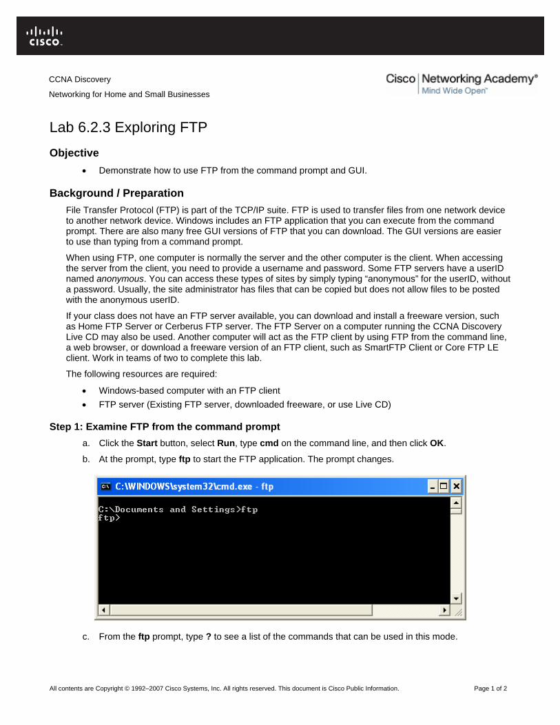
All contents are Copyright © 1992–2007 Cisco Systems, Inc. All rights reserved. This document is Cisco Public Information. Page 1 of 2
Lab 6.2.3 Exploring FTP Objective
• Demonstrate how to use FTP from the command prompt and GUI.
Background / Preparation File Transfer Protocol (FTP) is part of the TCP/IP suite. FTP is used to transfer files from one network device to another network device. Windows includes an FTP application that you can execute from the command prompt. There are also many free GUI versions of FTP that you can download. The GUI versions are easier to use than typing from a command prompt.
When using FTP, one computer is normally the server and the other computer is the client. When accessing the server from the client, you need to provide a username and password. Some FTP servers have a userID named anonymous. You can access these types of sites by simply typing “anonymous” for the userID, without a password. Usually, the site administrator has files that can be copied but does not allow files to be posted with the anonymous userID.
If your class does not have an FTP server available, you can download and install a freeware version, such as Home FTP Server or Cerberus FTP server. The FTP Server on a computer running the CCNA Discovery Live CD may also be used. Another computer will act as the FTP client by using FTP from the command line, a web browser, or download a freeware version of an FTP client, such as SmartFTP Client or Core FTP LE client. Work in teams of two to complete this lab.
The following resources are required:
• Windows-based computer with an FTP client • FTP server (Existing FTP server, downloaded freeware, or use Live CD)
Step 1: Examine FTP from the command prompt a. Click the Start button, select Run, type cmd on the command line, and then click OK.
b. At the prompt, type ftp to start the FTP application. The prompt changes.
c. From the ftp prompt, type ? to see a list of the commands that can be used in this mode.
CCNA Discovery
Networking for Home and Small Businesses
CCNA Discovery
Networking for Home and Small Businesses
All contents are Copyright © 1992–2007 Cisco Systems, Inc. All rights reserved. This document is Cisco Public Information. Page 2 of 2
d. List three FTP commands. _______________________________________________________
e. At the prompt, type help put to see a short description of the put command.
f. What is the purpose of the put command? ___________________________________________
g. Use the help command again to get the purpose of the get, send, and recv commands.
get __________________________________________________________________________
send _________________________________________________________________________
recv _________________________________________________________________________
NOTE: The original FTP commands were PUT to send a file to an FTP server and GET to download a file from the FTP server. You also had to select ASCII or binary file mode. If you download a binary file in ASCII mode it could end up being corrupted. Some of the newer graphical programs now use send and receive in their place.
h. Partner with another student. Using procedures demonstrated in previous labs, write down the names and IP addresses of each partner computer. It is very important to get these names correct. Some FTP applications allow you to use either the IP address or the computer name.
Computer 1: __________________________________________________________________
Computer 2: __________________________________________________________________
Step 2: Use a GUI FTP client or web browser a. If you are using a web browser as the FTP client, open the web browser and type
ftp://ip_address_of_FTP_server. If the FTP server is configured to use an anonymous userID, connect directly to the FTP server. Using the FTP client, download an available file from the server.
b. If you are using a GUI FTP client, open the application. For most FTP clients, you must configure a new connection by giving it a name, the IP address of the FTP server, and a username and password. You may have to type anonymous if the FTP server allows this type of connection. Some applications have a checkbox that allows an anonymous login. When you have configured the connection, connect to the FTP server and download a file.
c. What is the name of the file you downloaded from the FTP server? ______________________
d. List one example of when FTP might be beneficial to a computer technician. _______________
____________________________________________________________________________
____________________________________________________________________________
Step 3: (Optional) Use both an FTP server and client a. If you control both the FTP server and client, practice sending files to and getting files from the client
and the server.
b. Show your transferred files to another group of students.
c. Close the FTP server and client applications.

All contents are Copyright © 1992–2007 Cisco Systems, Inc. All rights reserved. This document is Cisco Public Information. Page 1 of 3
Lab 6.2.4 Configuring an Email Client Objectives
• Set up an email client. • Send and receive mail from a mail server. • Add an email account or change an existing one.
Background / Preparation An email application gives the user the ability to send and receive messages from another user located on the same local network or on the Internet. The messages are sent by the sending client and stored on an email server. Another email client with a mailbox on the server can then access the server at any time to receive stored messages that are destined for that client.
The following resources are required:
• Windows-based computer with Internet connectivity • Microsoft Outlook or other email client software
Step 1: Open Microsoft Outlook a. From the Start menu, select All Programs. Locate the Microsoft Office software.
b. Select Microsoft Office Outlook as the email program. If your computer does not have the Microsoft Office software, there are many free email software packages available on the Internet. Search the Internet to find a free email client that can be installed on your computer. The following instructions may vary depending on your email client.
Step 2: Set up an email account a. When you first start Microsoft Outlook, a screen appears with Email Upgrade Options. You can
choose to import email messages or address books from another account. Because this is your first email account, select the Do Not Upgrade button.
b. The next screen is the Email Accounts screen where you are asked if you want to configure an email account. Click Yes.
c. If Outlook has already been installed and setup for e-mail previously, you can start the Outlook application and click Tools, E-Mail Accounts and then select View or change existing e-mail account to see how the existing account is set up.
Step 3: Enter POP3 e-mail account information a. The next screen requires the user of the new account to fill in information. Enter your name and email
address. Your can get your email address from your Internet provider.
NOTE: If you do not have a real ISP email account, this step can be treated as a simulation. Just enter the information requested to become familiar with the process of creating an email account.
b. Enter your server information. Contact your Internet provider to locate the server information for the incoming and outgoing mail servers. Usually Internet providers put this information on their website in their help section.
CCNA Discovery
Networking for Home and Small Businesses

CCNA Discovery
Networking for Home and Small Businesses
All contents are Copyright © 1992–2007 Cisco Systems, Inc. All rights reserved. This document is Cisco Public Information. Page 2 of 3
c. What is your incoming (POP3) mail server? ________________________________________
d. What is your outgoing (SMTP) mail server? _________________________________________
e. Enter your username and password. Do not check the box to remember your password. This option is used when only one person uses the computer. If anyone else were to use the computer, they could easily gain access to all of the information in your email.
f. Click the Test Account Settings button. If everything is correct, the screen displays that the test was successful. If not, correct your information and try again.
NOTE: If this is a simulation, the test will not be successful and you can go to Steps 4 and 5.
g. Test your new account by sending an email to a friend in class.
Step 4: (Optional) Add another account or change an account a. Open Microsoft Outlook. From the Tools menu, select Email Accounts.
b. In this screen, you can add another email account or you can change information in an existing account.

CCNA Discovery
Networking for Home and Small Businesses
All contents are Copyright © 1992–2007 Cisco Systems, Inc. All rights reserved. This document is Cisco Public Information. Page 3 of 3
Step 5: Reflection a. What are the advantages or disadvantages to using email over regular postal mail?
____________________________________________________________________________
____________________________________________________________________________
b. What are the advantages or disadvantages to using email over an instant messaging program?
____________________________________________________________________________
____________________________________________________________________________
c. With a partner, discuss five (5) recommendations for email etiquette that should be considered when emailing friends and business colleagues.
____________________________________________________________________________
____________________________________________________________________________
____________________________________________________________________________
____________________________________________________________________________
All contents are Copyright © 1992–2007 Cisco Systems, Inc. All rights reserved. This document is Cisco Public Information. Page 1 of 3
Lab 7.2.5 Configuring a Wireless Access Point Objective
• Configure the wireless access point (AP) portion of a multi-function device to allow access to a wireless client.
Background / Preparation The Linksys WRT300N includes an integrated 4-port switch, a router and a wireless Access Point (AP). In this lab, you will configure the AP component of the multi-function device to allow access for wireless clients. The basic wireless capabilities of the multi-function device will be configured but this will not be a secure wireless network. Setting up a secure wireless network will be covered in a later lab.
The following resources are required:
• Windows XP based computer that is cabled to the multi-function device • Linksys WRT300N
Step 1: Verify connectivity between the computer and the multi-function device a. The computer used to configure the AP should be attached to one of the multi-function device’s
switch ports.
b. On the computer, click the Start button and select Run. Type cmd and click OK or press Enter.
c. At the command prompt, ping the multi-function device using the default IP address 192.168.1.1 or the IP that has been configured on the multi-function device’s port. Do not proceed until the ping succeeds.
d. Write down the command used to ping the multi-function device.
____________________________________________________________________________
NOTE: If the ping is not successful, try these troubleshooting steps:
• Check to make sure the IP address of the computer is on the 192.168.1.0 network. The computer must be on the same network as the multi-function device to be able to ping it. The DHCP service of the multi-function device is enabled by default. If the computer is configured as a DHCP client it should have a valid IP address and subnet mask. If the computer has a static IP address, it must be in on the 192.168.1.0 network and the subnet mask must be 255.255.255.0.
• Make sure the cable is a known-good straight-through cable. Test to verify. • Verify that the link light for the port where the computer is attached is lit. • Check whether the multi-function device has power.
If none of these steps correct the problem, check with your instructor.
CCNA Discovery
Networking for Home and Small Businesses

CCNA Discovery
Networking for Home and Small Businesses
All contents are Copyright © 1992–2007 Cisco Systems, Inc. All rights reserved. This document is Cisco Public Information. Page 2 of 3
Step 2: Log in to the multi-function device and configure the wireless network a. Open a web browser. In the address line, type http://ip_address, where ip_address is the IP address
of the wireless router (default is 192.168.1.1). At the prompt, leave the user name textbox empty, but type the password assigned to the router. The default password is admin. Click OK.
b. In the main menu, click on the Wireless option.
c. In the Basic Wireless Settings window, the Network Mode shows mixed by default, because the AP supports 802.11b, g, and n wireless devices. You can use any of these standards to connect to the AP. If the wireless portion of the multi-function device is NOT being used, the network mode would be set to Disabled. Leave the default of Mixed selected.
d. Delete the default SSID (linksys) in the Network Name (SSID) textbox. Enter a new SSID using your last name or name chosen by your instructor. SSIDs are case-sensitive.
e. Write down the exact SSID name that you are using. __________________________________
____________________________________________________________________________
f. Click on the Radio Band drop-down menu and write down the two options.
____________________________________________________________________________
g. For a wireless network that can use 802.11b, g, or n client devices, the default is Auto. Auto allows the Wide Channel option to be chosen and gives the best performance. The Standard Channel option is used if the wireless client devices are 802.11b or g, or both b and g. The Wide Channel option is used if only 802.11n client devices are being used. Leave the default of Auto selected.
h. SSID Broadcast is set to enabled by default, which enables the AP to periodically send out the SSID using the wireless antenna. Any wireless devices in the area can detect this broadcast. This is how clients detect nearby wireless networks.
i. Click on the Save Settings button. When the settings have been successfully saved, click on Continue.
j. The AP is now configured for a wireless network with the name (SSID) that you gave it. It is important to write down this information before starting the next lab or attaching any wireless NICs to the wireless network.

CCNA Discovery
Networking for Home and Small Businesses
All contents are Copyright © 1992–2007 Cisco Systems, Inc. All rights reserved. This document is Cisco Public Information. Page 3 of 3
Step 3: Reflection a. How many wireless networks do you think could be configured in one classroom? What would limit
this?
____________________________________________________________________________
____________________________________________________________________________
____________________________________________________________________________
b. What do you see as a potential security problem when you broadcast your SSID from the AP?
____________________________________________________________________________
____________________________________________________________________________
____________________________________________________________________________

All contents are Copyright © 1992–2007 Cisco Systems, Inc. All rights reserved. This document is Cisco Public Information. Page 1 of 4
Lab 7.2.6 Configuring a Wireless Client Objective
• Install and configure a driver for a wireless USB NIC for a wireless client computer. • Determine the version of the driver installed and check the Internet for updates.
Background / Preparation In this lab you will install a driver for a wireless USB NIC in a computer. The driver is a type of software that controls the wireless NIC. The driver comes on a CD with the NIC or can be downloaded from the Internet. Many manufacturers require that the driver is installed before the adapter is connected. The procedure described in this lab is for a Linksys USB 802.11g wireless NIC, but is similar to others. You should always follow the procedure recommended by the wireless NIC manufacturer.
The following resources are required:
• Windows XP-based computer with an available USB port • Wireless USB NIC and associated driver • Administrator rights to install the driver • Linksys WRT300N with wireless access configured from previous lab
Step 1: Install the wireless NIC driver a. Insert the CD that contains the wireless NIC driver into the CD/DVD drive and install the driver
according to the manufacturer recommendations. Most USB devices require that the driver be installed before the device is physically attached. Note that you may do part of the installation process now and part of it after the wireless NIC is installed.
b. Who is the manufacturer of the wireless NIC? ______________________________________
CCNA Discovery
Networking for Home and Small Businesses

CCNA Discovery
Networking for Home and Small Businesses
All contents are Copyright © 1992–2007 Cisco Systems, Inc. All rights reserved. This document is Cisco Public Information. Page 2 of 4
c. Describe how you installed the wireless NIC driver. ___________________________________
____________________________________________________________________________
Step 2: Install the wireless NIC a. When prompted, connect the USB NIC cable to an available USB port. Click Next to continue.
Step 3: Attach to the wireless network a. Most wireless NIC adapters have client software to control the NIC. The software shows any wireless
networks that are discovered. Select the SSID of the wireless network that you configured on the AP in a previous lab.
b. Which SSID are you using? ________________________________________________
c. If the wireless NIC did not connect to the wireless network, perform the appropriate troubleshooting.
d. What is the signal strength for the wireless NIC? _________________________________

CCNA Discovery
Networking for Home and Small Businesses
All contents are Copyright © 1992–2007 Cisco Systems, Inc. All rights reserved. This document is Cisco Public Information. Page 3 of 4
e. Did the wireless NIC see any other wireless networks in the area? _______ Why or why not?
____________________________________________________________________________
f. Show your active wireless connection to a fellow student or the lab assistant.
g. What is another name for a wireless host? __________________________________________
h. Is it better to use the client software from the wireless NIC manufacturer or let Windows XP control the wireless NIC? _____________________________________________________________
Step 4: Determine the NIC driver version a. Hardware manufacturers continually update drivers. The driver that ships with a NIC or other piece of
hardware is frequently not the most current.
b. To check the driver version for the NIC you installed, click Start, select Control Panel and then Network Connections. Right-click on the wireless connection and select Properties. Click the Configure button for the NIC and then the Driver tab. What is the name and version of the driver you installed? ___________________________________________________________________
Step 5: Determine if the NIC driver is the most current a. Search the NIC manufacturer web site for drivers that support the wirelss NIC you installed. Are
there more current ones available? _______________________________________________
b. What is the most current one listed? ______________________________________________
c. If there is a more current driver, how would you apply it? ______________________________
____________________________________________________________________________
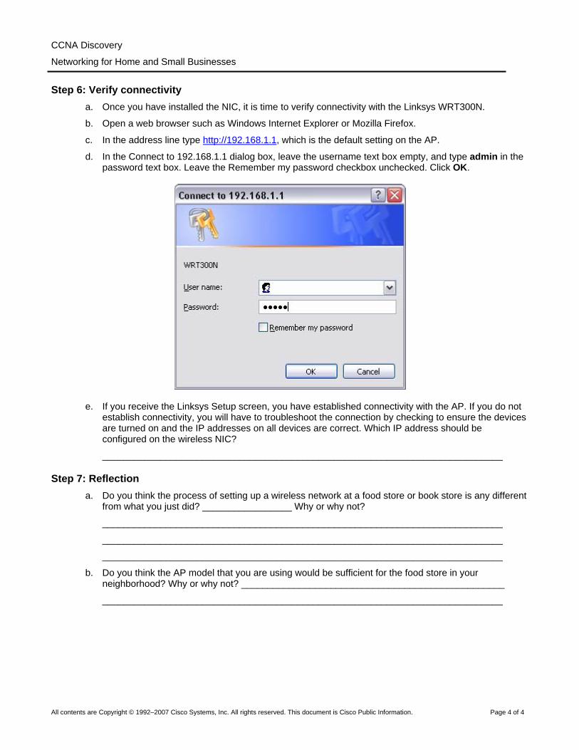
CCNA Discovery
Networking for Home and Small Businesses
All contents are Copyright © 1992–2007 Cisco Systems, Inc. All rights reserved. This document is Cisco Public Information. Page 4 of 4
Step 6: Verify connectivity a. Once you have installed the NIC, it is time to verify connectivity with the Linksys WRT300N.
b. Open a web browser such as Windows Internet Explorer or Mozilla Firefox.
c. In the address line type http://192.168.1.1, which is the default setting on the AP.
d. In the Connect to 192.168.1.1 dialog box, leave the username text box empty, and type admin in the password text box. Leave the Remember my password checkbox unchecked. Click OK.
e. If you receive the Linksys Setup screen, you have established connectivity with the AP. If you do not establish connectivity, you will have to troubleshoot the connection by checking to ensure the devices are turned on and the IP addresses on all devices are correct. Which IP address should be configured on the wireless NIC?
____________________________________________________________________________
Step 7: Reflection a. Do you think the process of setting up a wireless network at a food store or book store is any different
from what you just did? _________________ Why or why not?
____________________________________________________________________________
____________________________________________________________________________
____________________________________________________________________________
b. Do you think the AP model that you are using would be sufficient for the food store in your neighborhood? Why or why not? __________________________________________________
____________________________________________________________________________

All contents are Copyright © 1992–2007 Cisco Systems, Inc. All rights reserved. This document is Cisco Public Information. Page 1 of 8
Lab 7.3.5 Configuring Wireless Security Objectives
• Create a security plan for a home network. • Configure the wireless access point (AP) portion of a multi-function device using security best
practices.
Background / Preparation A well-planned security implementation is critical to the safety of a wireless network. This lab goes over the steps that must be taken to ensure the safety of the network using the following scenario.
You have just purchased a Linksys WRT300N wireless router, and you want to set up a small network in your home. You selected this router because the IEEE 802.11n specification claims that it has 12 times the speed of an 802.11g and 4 times the range. Because the 802.11n uses 2.4 GHz, it is backward compatible with both the 802.11b and 802.11g and uses MIMO (multiple-in, multiple-out) technology.
You should enable security mechanisms before connecting your multi-function device to the Internet or any wired network. You should also change the default values provided, because they are well-known values that are easily obtainable on the Internet.
The following resources are required:
• Windows-based computer • Linksys WRT300N • Straight-through Ethernet cable
Step 1: Plan the security for your home network a. List at least six security best practices that you should implement to secure your multi-function device
and wireless network.
1) __________________________________________________________________________
2) __________________________________________________________________________
3) __________________________________________________________________________
4) __________________________________________________________________________
5) __________________________________________________________________________
6) __________________________________________________________________________
b. Describe what the security risk is for each item.
1) __________________________________________________________________________
2) __________________________________________________________________________
3) __________________________________________________________________________
4) __________________________________________________________________________
5) __________________________________________________________________________
6) __________________________________________________________________________
CCNA Discovery
Networking for Home and Small Businesses
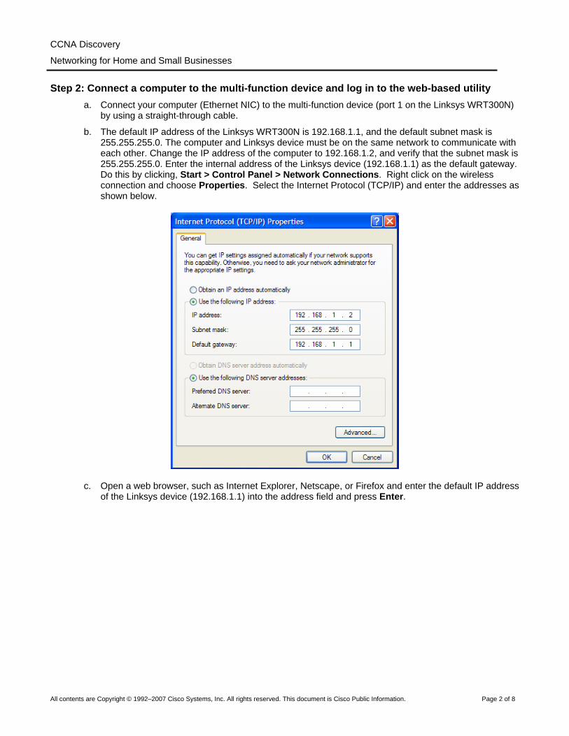
CCNA Discovery
Networking for Home and Small Businesses
All contents are Copyright © 1992–2007 Cisco Systems, Inc. All rights reserved. This document is Cisco Public Information. Page 2 of 8
Step 2: Connect a computer to the multi-function device and log in to the web-based utility a. Connect your computer (Ethernet NIC) to the multi-function device (port 1 on the Linksys WRT300N)
by using a straight-through cable.
b. The default IP address of the Linksys WRT300N is 192.168.1.1, and the default subnet mask is 255.255.255.0. The computer and Linksys device must be on the same network to communicate with each other. Change the IP address of the computer to 192.168.1.2, and verify that the subnet mask is 255.255.255.0. Enter the internal address of the Linksys device (192.168.1.1) as the default gateway. Do this by clicking, Start > Control Panel > Network Connections. Right click on the wireless connection and choose Properties. Select the Internet Protocol (TCP/IP) and enter the addresses as shown below.
c. Open a web browser, such as Internet Explorer, Netscape, or Firefox and enter the default IP address of the Linksys device (192.168.1.1) into the address field and press Enter.
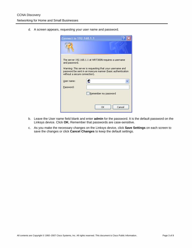
CCNA Discovery
Networking for Home and Small Businesses
All contents are Copyright © 1992–2007 Cisco Systems, Inc. All rights reserved. This document is Cisco Public Information. Page 3 of 8
d. A screen appears, requesting your user name and password.
b. Leave the User name field blank and enter admin for the password. It is the default password on the Linksys device. Click OK. Remember that passwords are case-sensitive.
c. As you make the necessary changes on the Linksys device, click Save Settings on each screen to save the changes or click Cancel Changes to keep the default settings.

CCNA Discovery
Networking for Home and Small Businesses
All contents are Copyright © 1992–2007 Cisco Systems, Inc. All rights reserved. This document is Cisco Public Information. Page 4 of 8
Step 4: Change the Linksys device password a. The initial screen displayed is the Setup > Basic Setup screen.
b. Click the Administration tab. The Management tab is selected by default.
c. Type in a new password for the Linksys device, and then confirm the password. The new password must not be more than 32 characters and must not include any spaces. The password is required to access the Linksys device web-based utility and Setup Wizard.
d. The Web Utility Access via Wireless option is enabled by default. You may want to disable this feature to further increase security.

CCNA Discovery
Networking for Home and Small Businesses
All contents are Copyright © 1992–2007 Cisco Systems, Inc. All rights reserved. This document is Cisco Public Information. Page 5 of 8
e. Click the Save Settings button to save the information.
NOTE: If you forget your password, you can reset the Linksys device to the factory defaults by pressing the RESET button for 5 seconds and then releasing it. The default password is admin.
Step 5: Configure the wireless security settings a. Click the Wireless tab. The Basic Wireless Settings tab is selected by default. The Network Name
is the SSID shared among all devices on your network. It must be identical for all devices in the wireless network. It is case-sensitive and must not be more than 32 characters.
b. Change the SSID from the default of linksys to a unique name. Record the name you have chosen: _____________________________________________________________________________
c. Leave the Radio Band set to Auto. This allows your network to use all 802.11n, g, and b devices.
d. For SSID Broadcast, select the Disabled button to disable the SSID broadcast. Wireless clients survey the area for networks to associate with and will detect the SSID broadcast sent by the Linksys device. For added security, do not broadcast the SSID.
e. Save your settings before going to the next screen.
Step 6: Configure encryption and authentication a. Choose the Wireless Security tab on the Wireless screen.
b. This router supports four types of security mode settings:
• WEP (Wired Equivalent Privacy) • WPA (Wi-Fi Protected Access) Personal, which uses a pre-shared key (PSK) • WPA Enterprise, which uses Remote Access Dial In User Service (RADIUS) • RADIUS

CCNA Discovery
Networking for Home and Small Businesses
All contents are Copyright © 1992–2007 Cisco Systems, Inc. All rights reserved. This document is Cisco Public Information. Page 6 of 8
c. Select WPA Personal Security Mode.
d. On the next screen, choose an Encryption algorithm.
To secure a network, use the highest level of encryption possible within the Selected Security mode. The following Security Modes and Encryption levels are listed from least secure (WEP) to most secure (WPA2 with AES)
• WEP • WPA
o TKIP (Temporal Key Integrity Protocol) o AES (Advanced Encryption System)
• WPA2 o TKIP o AES
AES is only supported by newer devices that contain a co-processor. To ensure compatibility with all devices, select TKIP.
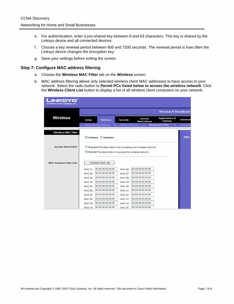
CCNA Discovery
Networking for Home and Small Businesses
All contents are Copyright © 1992–2007 Cisco Systems, Inc. All rights reserved. This document is Cisco Public Information. Page 7 of 8
e. For authentication, enter a pre-shared key between 8 and 63 characters. This key is shared by the Linksys device and all connected devices.
f. Choose a key renewal period between 600 and 7200 seconds. The renewal period is how often the Linksys device changes the encryption key.
g. Save your settings before exiting the screen.
Step 7: Configure MAC address filtering a. Choose the Wireless MAC Filter tab on the Wireless screen.
b. MAC address filtering allows only selected wireless client MAC addresses to have access to your network. Select the radio button to Permit PCs listed below to access the wireless network. Click the Wireless Client List button to display a list of all wireless client computers on your network.

CCNA Discovery
Networking for Home and Small Businesses
All contents are Copyright © 1992–2007 Cisco Systems, Inc. All rights reserved. This document is Cisco Public Information. Page 8 of 8
c. The next screen allows you to identify which MAC addresses can have access to the wireless network. Click the Save to MAC Address Filter List check box for any client device you want to add, and then click the Add button. Any wireless clients, other than those in the list will be prevented from accessing your wireless network. Save your settings before exiting the screen.
Step 8: Reflection a. Which feature that you configured on the Linksys WRT300N makes you feel the most secure and
why?
____________________________________________________________________________
____________________________________________________________________________
____________________________________________________________________________
b. Make a list of other items that could be done to make your network even more secure.
____________________________________________________________________________
____________________________________________________________________________
____________________________________________________________________________

CCNA Discovery
Networking for Home and Small Businesses
Lab 8.4.2 Configuring Access Policies and DMZ Settings
Objectives • Log in to a multi-function device and view security settings. • Set up Internet access policies based on IP address and application. • Set up a DMZ for an open access server with a static IP address. • Set up port forwarding to limit port accessibility to only HTTP. • Use the Linksys WRT300N Help features.
Background / Preparation This lab provides instructions for configuring security settings for the Linksys WRT300N. The Linksys provides a software-based firewall to protect internal, local-network clients from attack by external hosts. Connections from internal hosts to external destinations can be filtered based on the IP address, destination website, and application. The Linksys can also be configured to create a demilitarized zone (DMZ) to control access to a server from external hosts. This lab is done in teams of two, and two teams can work together to test each other’s access restrictions and DMZ functionality. It is divided into 2 parts:
• Part 1 – Configuring access policies • Part 2 – Configuring DMZ settings
The following resources are required:
• Linksys WRT300N or other multi-function device with the default configuration • User ID and password for the Linksys device if different than the default • Computer running Windows XP Professional to access the Linksys GUI • Internal PC to act as a server in the DMZ with HTTP and Telnet servers installed (preconfigured or
Discovery Live CD server) • External server to represent the ISP and Internet (with preconfigured DHCP, HTTP, and Telnet
servers running (real server with services installed or Discovery Live CD server) • Cabling to connect the PC hosts, Linksys WRT300N or multi-function device, and switches
All contents are Copyright © 1992–2007 Cisco Systems, Inc. All rights reserved. This document is Cisco Public Information. Page 1 of 9

CCNA Discovery
Networking for Home and Small Businesses
Part 1 – Configuring access policies
Step 1: Build the network and configure the hosts a. Connect the host computers to switch ports on the multi-function device as shown in the topology
diagram. Host-A is the console and is used to access the Linksys GUI. Host-B is initially a test machine but later becomes the DMZ server.
b. Configure the IP settings for both hosts using Windows XP Network Connections and TCP/IP properties. Verify that Host-A is configured as a DHCP client. Assign a static IP address to Host-B in the 192.168.1.x range with a subnet mask of 255.255.255.0. The default gateway should be the internal local network address of the Linksys device.
NOTE: If Host-B is already a DHCP client, you can reserve its current address and make it static using the DHCP Reservation feature on the Linksys Basic Setup screen.
c. Use the ipconfig command to display the IP address, subnet mask, and default gateway for Host-A and Host-B and record them in the table. Obtain the IP address and subnet mask of the external server from the instructor and record it in the table.
Host IP Address Subnet Mask Default Gateway
Host-A
Host-B / DMZ Server
External Server
All contents are Copyright © 1992–2007 Cisco Systems, Inc. All rights reserved. This document is Cisco Public Information. Page 2 of 9

CCNA Discovery
Networking for Home and Small Businesses
Step 2: Log in to the user interface a. To access the Linksys or multi-function device web-based GUI, open a browser and enter the default
internal IP address for the device, normally 192.168.1.1.
b. Log in using the default user ID and password, or check with the instructor if they are different.
c. The multi-function device should be configured to obtain an IP address from the external DHCP server. The default screen after logging in to the multi-function device is Setup > Basic Setup. What is the Internet connection type?
____________________________________________________________________________
d. What is the default router (internal) IP address and subnet mask for the multi-function device?
____________________________________________________________________________
e. Verify that the multi-function device has received an external IP address from the DHCP server by clicking the Status > Router tab.
f. What is the external IP address and subnet mask assigned to the multi-function device? ____________________________________________________________________________
All contents are Copyright © 1992–2007 Cisco Systems, Inc. All rights reserved. This document is Cisco Public Information. Page 3 of 9

CCNA Discovery
Networking for Home and Small Businesses
Step 3: View multi-function device firewall settings a. The Linksys WRT300N provides a basic firewall that uses Network Address Translation (NAT). In
addition, it provides additional firewall functionality using Stateful Packet Inspection (SPI) to detect and block unsolicited traffic from the Internet.
b. From the main screen, click the Security tab to view the Firewall and Internet Filter status. What is the status of SPI Firewall protection? ______________________________________________
c. Which Internet Filter checkboxes are selected? _____________________________________
d. Click Help to learn more about these settings. What benefits does filtering IDENT provide?
____________________________________________________________________________
All contents are Copyright © 1992–2007 Cisco Systems, Inc. All rights reserved. This document is Cisco Public Information. Page 4 of 9

CCNA Discovery
Networking for Home and Small Businesses
Step 4: Set up Internet access restrictions based on IP address
In Lab 7.3.5, you saw that wireless security features can be used to control which wireless client computers can access the multi-function device, based on their MAC address. This prevents unauthorized external computers from connecting to the wireless access point (AP) and gaining access to the internal local network and the Internet.
The multi-function device can also control which internal users can get out to the Internet from the local network. You can create an Internet access policy to deny or allow specific internal computers access to the Internet based on the IP address, MAC address, and other criteria.
a. From the main multi-function device screen, click the Access Restrictions tab to define Access Policy 1.
b. Enter Block-IP as the policy name. Select Enabled to enable the policy, and then select Deny to prevent Internet access from a specified IP address.
c. Click the Edit List button and enter the IP address of Host-B. Click Save Settings and then Close. Click Save Settings to save Internet Access Policy 1 – Block IP.
d. Test the policy by attempting to access the external web server from Host-B. Open a browser and enter the IP address of the external server in the address area. Are you able to access the server? ____________________________________________________________________________
e. Change the status of the Block-IP Policy to Disabled and click Save Settings. Are you able to access the server now? _________________________________________________________
f. What other ways can access policies be used to block Internet access?
____________________________________________________________________________
All contents are Copyright © 1992–2007 Cisco Systems, Inc. All rights reserved. This document is Cisco Public Information. Page 5 of 9
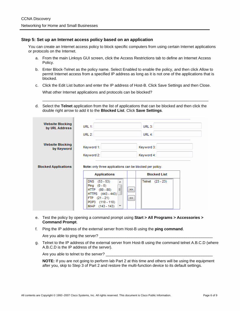
CCNA Discovery
Networking for Home and Small Businesses
Step 5: Set up an Internet access policy based on an application You can create an Internet access policy to block specific computers from using certain Internet applications or protocols on the Internet.
a. From the main Linksys GUI screen, click the Access Restrictions tab to define an Internet Access Policy.
b. Enter Block-Telnet as the policy name. Select Enabled to enable the policy, and then click Allow to permit Internet access from a specified IP address as long as it is not one of the applications that is blocked.
c. Click the Edit List button and enter the IP address of Host-B. Click Save Settings and then Close.
What other Internet applications and protocols can be blocked?
____________________________________________________________________________
d. Select the Telnet application from the list of applications that can be blocked and then click the double right arrow to add it to the Blocked List. Click Save Settings.
e. Test the policy by opening a command prompt using Start > All Programs > Accessories > Command Prompt.
f. Ping the IP address of the external server from Host-B using the ping command.
Are you able to ping the server? ____________________________________________________
g. Telnet to the IP address of the external server from Host-B using the command telnet A.B.C.D (where A.B.C.D is the IP address of the server).
Are you able to telnet to the server? _________________________________________________
NOTE: If you are not going to perform lab Part 2 at this time and others will be using the equipment after you, skip to Step 3 of Part 2 and restore the multi-function device to its default settings.
All contents are Copyright © 1992–2007 Cisco Systems, Inc. All rights reserved. This document is Cisco Public Information. Page 6 of 9

CCNA Discovery
Networking for Home and Small Businesses
Part 2 – Configuring a DMZ on the multi-function device
Step 1: Set up a simple DMZ It is sometimes necessary to allow access to a computer from the Internet while still protecting other internal local network computers. To accomplish this, you can set up a demilitarized zone (DMZ) that allows open access to any ports and services running on the specified server. Any requests made for services to the outside address of the multi-function device will be redirected to the server specified.
a. Host-B will act as the DMZ server and should be running HTTP and Telnet servers. Verify the Host-B has a static IP address or, if Host-B is a DHCP client, you can reserve its current address and make it static using the DHCP Reservation feature on the Linksys device Basic Setup screen.
b. From the main Linksys GUI screen, click the Applications & Gaming tab then click DMZ.
c. Click Help to learn more about the DMZ. For what other reasons might you want to set up a host in the DMZ?
____________________________________________________________________________
d. The DMZ feature is disabled by default. Select Enabled to enable the DMZ. Leave the Source IP
Address selected as Any IP Address, and enter the IP address of Host-B in the Destination IP address. Click Save Settings and click Continue when prompted.
e. Test basic access to the DMZ server by pinging from the external server to the outside address of the multi-function device. Use the ping –a command to verify that it is actually the DMZ server responding and not the multi-function device. Are you able to ping the DMZ server? ______________________________________________________________________________
f. Test HTTP access to the DMZ server by opening a browser on the external server and pointing to the external IP address of the multi-function device. Try the same thing from a browser on Host-A to Host-B using the internal addresses.
Are you able to access the web page? _______________________________________________
g. Test Telnet access by opening a command prompt as described in Step 5. Telnet to the outside IP address of the multi-function device using the command telnet A.B.C.D (where A.B.C.D is the outside address of the multi-function device).
Are you able to telnet to the server? ___________________________________________________
All contents are Copyright © 1992–2007 Cisco Systems, Inc. All rights reserved. This document is Cisco Public Information. Page 7 of 9
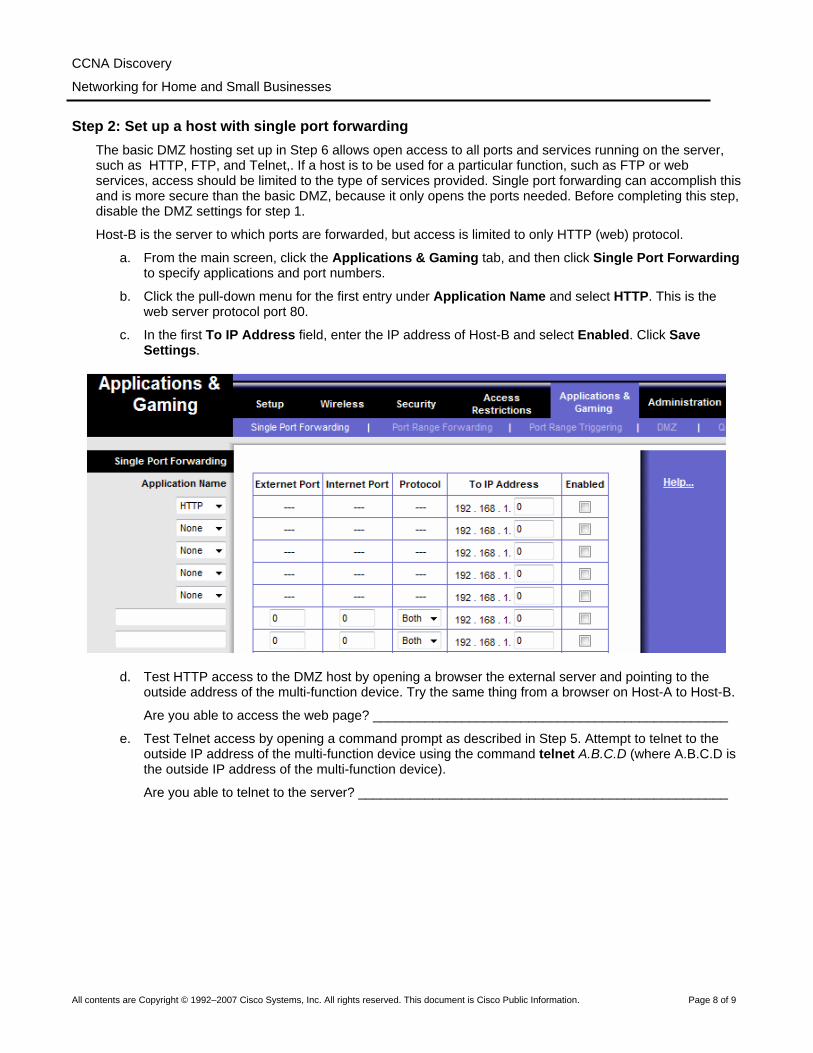
CCNA Discovery
Networking for Home and Small Businesses
Step 2: Set up a host with single port forwarding
The basic DMZ hosting set up in Step 6 allows open access to all ports and services running on the server, such as HTTP, FTP, and Telnet,. If a host is to be used for a particular function, such as FTP or web services, access should be limited to the type of services provided. Single port forwarding can accomplish this and is more secure than the basic DMZ, because it only opens the ports needed. Before completing this step, disable the DMZ settings for step 1.
Host-B is the server to which ports are forwarded, but access is limited to only HTTP (web) protocol.
a. From the main screen, click the Applications & Gaming tab, and then click Single Port Forwarding to specify applications and port numbers.
b. Click the pull-down menu for the first entry under Application Name and select HTTP. This is the web server protocol port 80.
c. In the first To IP Address field, enter the IP address of Host-B and select Enabled. Click Save Settings.
d. Test HTTP access to the DMZ host by opening a browser the external server and pointing to the outside address of the multi-function device. Try the same thing from a browser on Host-A to Host-B.
Are you able to access the web page? ________________________________________________
e. Test Telnet access by opening a command prompt as described in Step 5. Attempt to telnet to the outside IP address of the multi-function device using the command telnet A.B.C.D (where A.B.C.D is the outside IP address of the multi-function device).
Are you able to telnet to the server? __________________________________________________
All contents are Copyright © 1992–2007 Cisco Systems, Inc. All rights reserved. This document is Cisco Public Information. Page 8 of 9
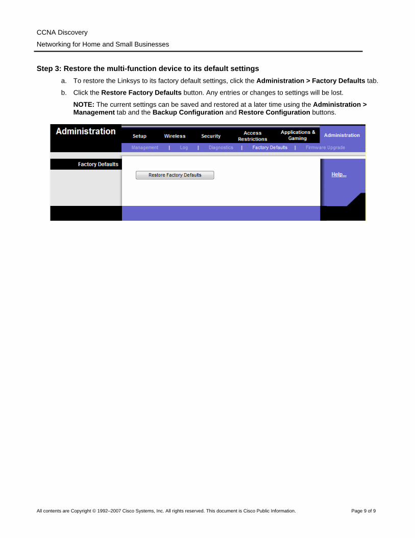
CCNA Discovery
Networking for Home and Small Businesses
Step 3: Restore the multi-function device to its default settings a. To restore the Linksys to its factory default settings, click the Administration > Factory Defaults tab.
b. Click the Restore Factory Defaults button. Any entries or changes to settings will be lost.
NOTE: The current settings can be saved and restored at a later time using the Administration > Management tab and the Backup Configuration and Restore Configuration buttons.
All contents are Copyright © 1992–2007 Cisco Systems, Inc. All rights reserved. This document is Cisco Public Information. Page 9 of 9
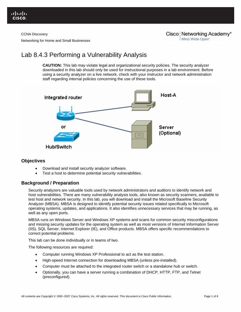
CCNA Discovery
Networking for Home and Small Businesses
Lab 8.4.3 Performing a Vulnerability Analysis
CAUTION: This lab may violate legal and organizational security policies. The security analyzer downloaded in this lab should only be used for instructional purposes in a lab environment. Before using a security analyzer on a live network, check with your instructor and network administration staff regarding internal policies concerning the use of these tools.
Objectives • Download and install security analyzer software. • Test a host to determine potential security vulnerabilities.
Background / Preparation Security analyzers are valuable tools used by network administrators and auditors to identify network and host vulnerabilities. There are many vulnerability analysis tools, also known as security scanners, available to test host and network security. In this lab, you will download and install the Microsoft Baseline Security Analyzer (MBSA). MBSA is designed to identify potential security issues related specifically to Microsoft operating systems, updates, and applications. It also identifies unnecessary services that may be running, as well as any open ports.
MBSA runs on Windows Server and Windows XP systems and scans for common security misconfigurations and missing security updates for the operating system as well as most versions of Internet Information Server (IIS), SQL Server, Internet Explorer (IE), and Office products. MBSA offers specific recommendations to correct potential problems.
This lab can be done individually or in teams of two.
The following resources are required:
• Computer running Windows XP Professional to act as the test station. • High-speed Internet connection for downloading MBSA (unless pre-installed). • Computer must be attached to the integrated router switch or a standalone hub or switch. • Optionally, you can have a server running a combination of DHCP, HTTP, FTP, and Telnet
(preconfigured).
All contents are Copyright © 1992–2007 Cisco Systems, Inc. All rights reserved. This document is Cisco Public Information. Page 1 of 8
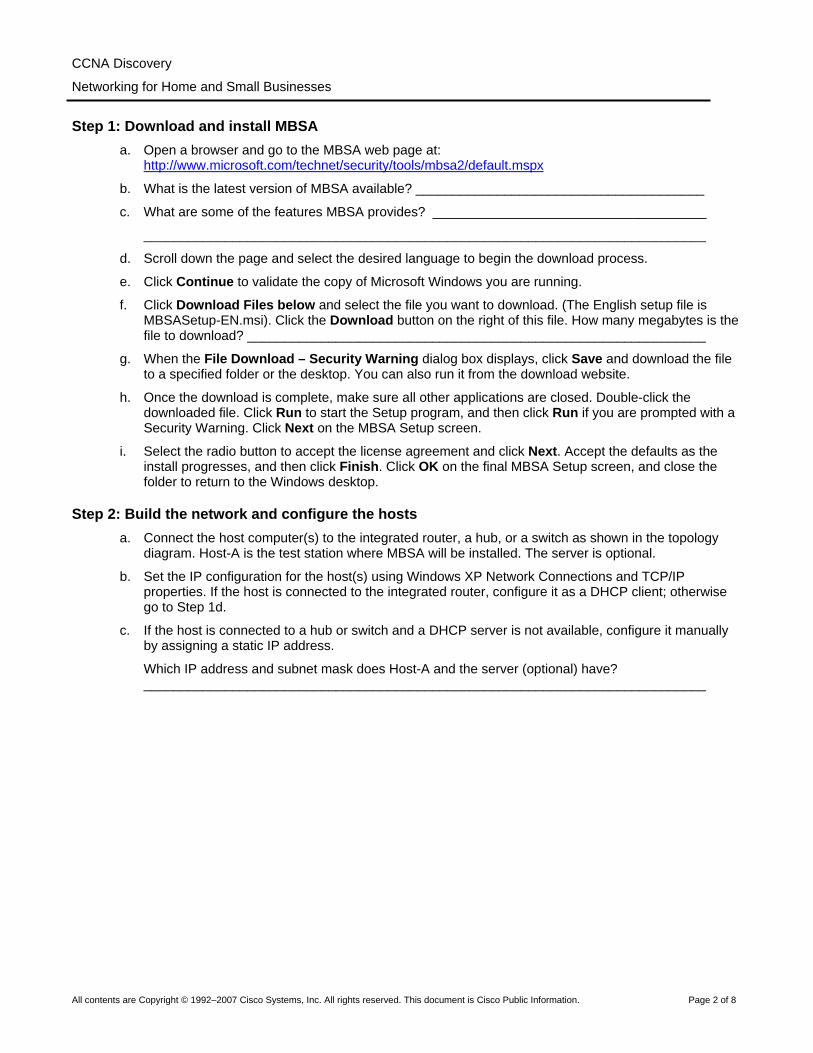
CCNA Discovery
Networking for Home and Small Businesses
Step 1: Download and install MBSA
a. Open a browser and go to the MBSA web page at: http://www.microsoft.com/technet/security/tools/mbsa2/default.mspx
b. What is the latest version of MBSA available? _______________________________________
c. What are some of the features MBSA provides? _____________________________________
____________________________________________________________________________
d. Scroll down the page and select the desired language to begin the download process.
e. Click Continue to validate the copy of Microsoft Windows you are running.
f. Click Download Files below and select the file you want to download. (The English setup file is MBSASetup-EN.msi). Click the Download button on the right of this file. How many megabytes is the file to download? ______________________________________________________________
g. When the File Download – Security Warning dialog box displays, click Save and download the file to a specified folder or the desktop. You can also run it from the download website.
h. Once the download is complete, make sure all other applications are closed. Double-click the downloaded file. Click Run to start the Setup program, and then click Run if you are prompted with a Security Warning. Click Next on the MBSA Setup screen.
i. Select the radio button to accept the license agreement and click Next. Accept the defaults as the install progresses, and then click Finish. Click OK on the final MBSA Setup screen, and close the folder to return to the Windows desktop.
Step 2: Build the network and configure the hosts a. Connect the host computer(s) to the integrated router, a hub, or a switch as shown in the topology
diagram. Host-A is the test station where MBSA will be installed. The server is optional.
b. Set the IP configuration for the host(s) using Windows XP Network Connections and TCP/IP properties. If the host is connected to the integrated router, configure it as a DHCP client; otherwise go to Step 1d.
c. If the host is connected to a hub or switch and a DHCP server is not available, configure it manually by assigning a static IP address.
Which IP address and subnet mask does Host-A and the server (optional) have? ____________________________________________________________________________
All contents are Copyright © 1992–2007 Cisco Systems, Inc. All rights reserved. This document is Cisco Public Information. Page 2 of 8

CCNA Discovery
Networking for Home and Small Businesses
Step 3: Run MBSA on a host a. Double-click the desktop icon for MBSA or run it from Start > All Programs.
When the main screen displays, which options are available? ___________________________
____________________________________________________________________________
All contents are Copyright © 1992–2007 Cisco Systems, Inc. All rights reserved. This document is Cisco Public Information. Page 3 of 8
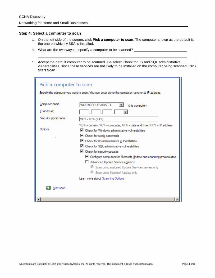
CCNA Discovery
Networking for Home and Small Businesses
Step 4: Select a computer to scan
a. On the left side of the screen, click Pick a computer to scan. The computer shown as the default is the one on which MBSA is installed.
b. What are the two ways to specify a computer to be scanned? ___________________________
____________________________________________________________________________
c. Accept the default computer to be scanned. De-select Check for IIS and SQL administrative vulnerabilities, since these services are not likely to be installed on the computer being scanned. Click Start Scan.
All contents are Copyright © 1992–2007 Cisco Systems, Inc. All rights reserved. This document is Cisco Public Information. Page 4 of 8

CCNA Discovery
Networking for Home and Small Businesses
Step 5: View security update scan results
a. View the security report. What are the results of the security update scan? ________________
____________________________________________________________________________
b. If there are any red or yellow Xs, click How to correct this. Which solution is recommended?
____________________________________________________________________________
All contents are Copyright © 1992–2007 Cisco Systems, Inc. All rights reserved. This document is Cisco Public Information. Page 5 of 8

CCNA Discovery
Networking for Home and Small Businesses
Step 6: View Windows scan results in the security report
a. Scroll down to view the second section of the report that shows Windows Scan Results. Were there any administrative vulnerabilities identified?
____________________________________________________________________________
b. On the Additional System Information section of the screen (below), in the Issue column for
Services, click What was scanned, and click Result details under the Result column to get a description of the check that was run. What did you find? When finished, close both popup windows to return to the security report.
____________________________________________________________________________
All contents are Copyright © 1992–2007 Cisco Systems, Inc. All rights reserved. This document is Cisco Public Information. Page 6 of 8
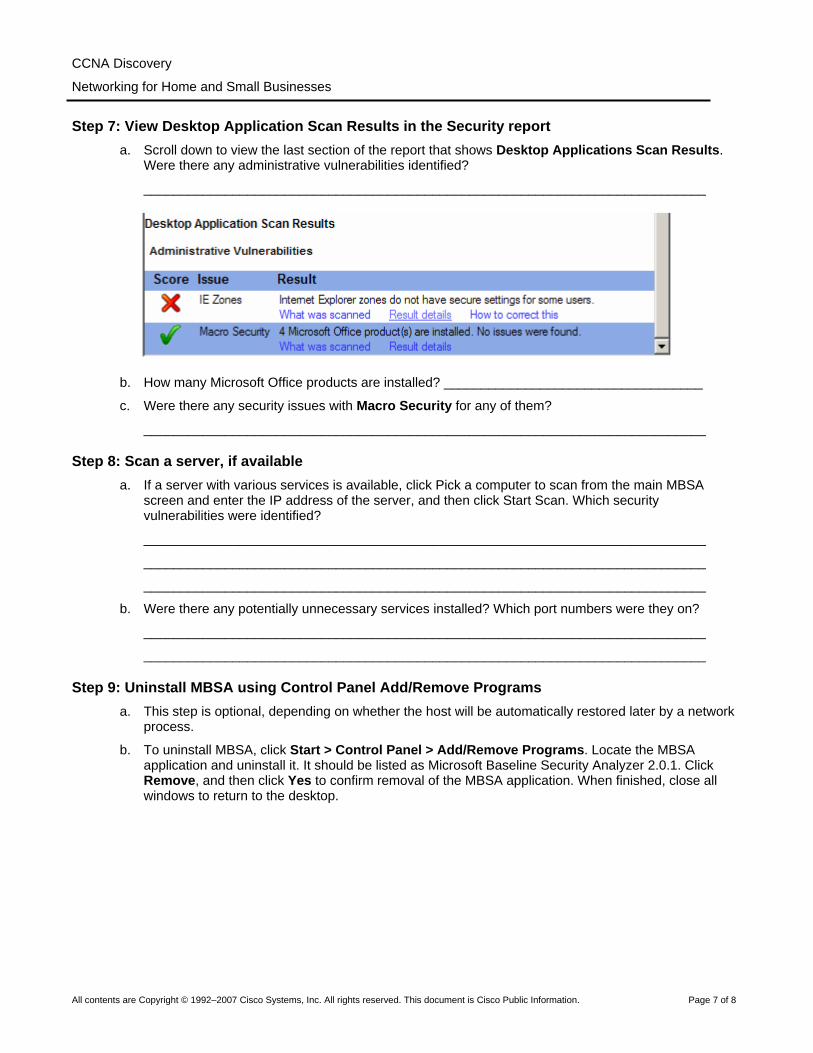
CCNA Discovery
Networking for Home and Small Businesses
Step 7: View Desktop Application Scan Results in the Security report
a. Scroll down to view the last section of the report that shows Desktop Applications Scan Results. Were there any administrative vulnerabilities identified?
____________________________________________________________________________
b. How many Microsoft Office products are installed? ___________________________________
c. Were there any security issues with Macro Security for any of them?
____________________________________________________________________________
Step 8: Scan a server, if available a. If a server with various services is available, click Pick a computer to scan from the main MBSA
screen and enter the IP address of the server, and then click Start Scan. Which security vulnerabilities were identified?
____________________________________________________________________________
____________________________________________________________________________
____________________________________________________________________________
b. Were there any potentially unnecessary services installed? Which port numbers were they on?
____________________________________________________________________________
____________________________________________________________________________
Step 9: Uninstall MBSA using Control Panel Add/Remove Programs a. This step is optional, depending on whether the host will be automatically restored later by a network
process.
b. To uninstall MBSA, click Start > Control Panel > Add/Remove Programs. Locate the MBSA application and uninstall it. It should be listed as Microsoft Baseline Security Analyzer 2.0.1. Click Remove, and then click Yes to confirm removal of the MBSA application. When finished, close all windows to return to the desktop.
All contents are Copyright © 1992–2007 Cisco Systems, Inc. All rights reserved. This document is Cisco Public Information. Page 7 of 8

CCNA Discovery
Networking for Home and Small Businesses
Step 10: Reflection a. The MBSA tool is designed to identify vulnerabilities for Windows-based computers. Search the
Internet for other tools that might exist. List some of the tools discovered.
____________________________________________________________________________
b. Which tools might there be for non-Windows computers? Search the Internet for other tools that might exist and list some of them here.
____________________________________________________________________________
c. Which other steps could you take to help secure a computer against Internet attacks?
____________________________________________________________________________
All contents are Copyright © 1992–2007 Cisco Systems, Inc. All rights reserved. This document is Cisco Public Information. Page 8 of 8
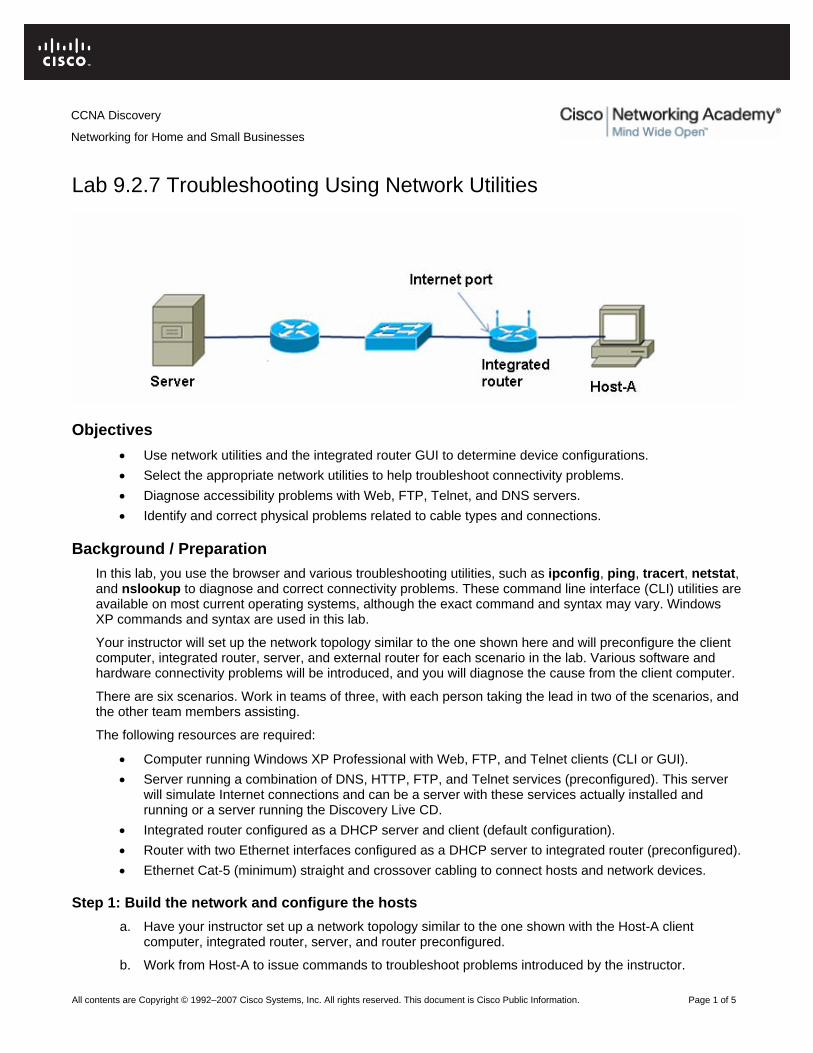
CCNA Discovery
Networking for Home and Small Businesses
Lab 9.2.7 Troubleshooting Using Network Utilities
Objectives • Use network utilities and the integrated router GUI to determine device configurations. • Select the appropriate network utilities to help troubleshoot connectivity problems. • Diagnose accessibility problems with Web, FTP, Telnet, and DNS servers. • Identify and correct physical problems related to cable types and connections.
Background / Preparation In this lab, you use the browser and various troubleshooting utilities, such as ipconfig, ping, tracert, netstat, and nslookup to diagnose and correct connectivity problems. These command line interface (CLI) utilities are available on most current operating systems, although the exact command and syntax may vary. Windows XP commands and syntax are used in this lab.
Your instructor will set up the network topology similar to the one shown here and will preconfigure the client computer, integrated router, server, and external router for each scenario in the lab. Various software and hardware connectivity problems will be introduced, and you will diagnose the cause from the client computer.
There are six scenarios. Work in teams of three, with each person taking the lead in two of the scenarios, and the other team members assisting.
The following resources are required:
• Computer running Windows XP Professional with Web, FTP, and Telnet clients (CLI or GUI). • Server running a combination of DNS, HTTP, FTP, and Telnet services (preconfigured). This server
will simulate Internet connections and can be a server with these services actually installed and running or a server running the Discovery Live CD.
• Integrated router configured as a DHCP server and client (default configuration). • Router with two Ethernet interfaces configured as a DHCP server to integrated router (preconfigured). • Ethernet Cat-5 (minimum) straight and crossover cabling to connect hosts and network devices.
Step 1: Build the network and configure the hosts a. Have your instructor set up a network topology similar to the one shown with the Host-A client
computer, integrated router, server, and router preconfigured.
b. Work from Host-A to issue commands to troubleshoot problems introduced by the instructor.
All contents are Copyright © 1992–2007 Cisco Systems, Inc. All rights reserved. This document is Cisco Public Information. Page 1 of 5
CCNA Discovery
Networking for Home and Small Businesses
c. All commands are issued from a command prompt window. Open a command prompt window by
clicking Start > All Programs > Accessories > Command Prompt. Keep the window open for the duration of the lab.
Step 2: Record the baseline IP address information for computers and integrated router NOTE: Perform this step before the instructor introduces problems.
a. Host-A configuration—Issue the command that displays the IP address information for Host-A, including the DNS server, and record the information below. Which command did you use? __________________
IP address: ________________________________
Subnet mask: ______________________________
Default gateway IP address: __________________
DNS server IP address: ______________________
DHCP server IP address: _____________________
How did Host-A obtain its IP address? ___________
b. Integrated router configuration—From Host-A, open a browser and go to the integrated router GUI by entering 192.168.1.1 as the URL address. Log in to the integrated router using the default user ID and password (check with your instructor if necessary). Check the internal and external IP address information and record it below.
Internal IP address: _________________________
Subnet mask: ______________________________
Is the DHCP server enabled? __________________
External (Internet) IP address: _________________
Subnet mask: ______________________________
Default gateway IP address: __________________
DNS server IP address: ______________________
c. Server configuration—Obtain the Server IP configuration from your instructor and record the information below.
IP address: ________________________________
Subnet mask: ______________________________
Default gateway IP address: __________________
Web Server 1 protocol and name: ________________________
Web Server 2 protocol and name: ________________________
FTP Server 1 protocol and name: ________________________
FTP Server 2 protocol and name: ________________________
Step 3: Scenario 1—Diagnose Web server access a. After your instructor sets up the problem for this scenario, use various utilities to diagnose the
problem.
b. Open your browser and enter the name of the Web Server 1 from Step 2. What happened?
____________________________________________________________________________
All contents are Copyright © 1992–2007 Cisco Systems, Inc. All rights reserved. This document is Cisco Public Information. Page 2 of 5

CCNA Discovery
Networking for Home and Small Businesses
c. Which commands did you use to diagnose the problem? _______________________________
d. Report the problem or suspected problem to the instructor. What was the problem?
____________________________________________________________________________
e. What did you do to correct the problem, if anything?
____________________________________________________________________________
f. You may need to contact the instructor to correct the problem. When the problem is corrected, retest and verify access to the server.
Step 4: Scenario 2—Diagnose Web server access a. After your instructor sets up the problem for this scenario, use various utilities to diagnose the
problem.
b. Open your browser and enter the name of the Web Server 2 from Step 2. What happened?
____________________________________________________________________________
c. Which commands did you use to diagnose the problem? _______________________________
____________________________________________________________________________
____________________________________________________________________________
d. Report the problem or suspected problem to the instructor. What was the problem?
____________________________________________________________________________
____________________________________________________________________________
____________________________________________________________________________
e. What did you do to correct the problem, if anything?
____________________________________________________________________________
____________________________________________________________________________
____________________________________________________________________________
f. You may need to contact the instructor to correct the problem. When the problem is corrected, retest and verify access to the server.
Step 5: Scenario 3—Diagnose FTP server access a. After your instructor sets up the problem for scenario, use various utilities to diagnose the problem.
b. Use your FTP client (CLI or GUI) to connect to FTP Server 1 from Step 2. What happened?
____________________________________________________________________________
c. Which commands did you use to diagnose the problem? ______________________________
____________________________________________________________________________
____________________________________________________________________________
d. Report the problem or suspected problem to the instructor. What was the problem?
____________________________________________________________________________
____________________________________________________________________________
e. What did you do to correct the problem, if anything?
____________________________________________________________________________
All contents are Copyright © 1992–2007 Cisco Systems, Inc. All rights reserved. This document is Cisco Public Information. Page 3 of 5

CCNA Discovery
Networking for Home and Small Businesses
f. You may need to contact the instructor to correct the problem. When the problem is corrected, retest
and verify access to the server.
Step 6: Scenario 4—Diagnose FTP server access a. After your instructor sets up the problem for this scenario, use various utilities to diagnose the
problem.
b. Use your FTP client (CLI or GUI) to connect to FTP Server 2 from Step 2. What happened?
___________________________________________________________________________
c. Which commands did you use to diagnose the problem? ______________________________
____________________________________________________________________________
____________________________________________________________________________
d. Report the problem or suspected problem to the instructor. What was the problem?
____________________________________________________________________________
____________________________________________________________________________
____________________________________________________________________________
e. What did you do to correct the problem, if anything?
____________________________________________________________________________
f. You may need to contact the instructor to correct the problem. When the problem is corrected, retest and verify access to the server.
Step 7: Scenario 5—Diagnose Telnet server access problem a. After your instructor sets up the problem for this scenario, use various utilities to diagnose the
problem.
b. Use a Telnet client (CLI or GUI) to connect to the name of Server 1 identified in Step 2. What happened? __________________________________________________________________
c. Which commands did you use to diagnose the problem? _______________________________
____________________________________________________________________________
____________________________________________________________________________
d. Report the problem or suspected problem to the instructor. What was the problem?
____________________________________________________________________________
____________________________________________________________________________
____________________________________________________________________________
e. What did you do to correct the problem, if anything?
____________________________________________________________________________
f. You may need to contact the instructor to correct the problem. When the problem is corrected, retest and verify access to the server.
Step 8: Scenario 6—Analyze TCP connections to Host-A a. Ask your instructor to verify that all problems introduced with the lab setup have been corrected.
Using the appropriate clients, connect to the Web, FTP, and Telnet servers simultaneously from Host-A.
All contents are Copyright © 1992–2007 Cisco Systems, Inc. All rights reserved. This document is Cisco Public Information. Page 4 of 5

CCNA Discovery
Networking for Home and Small Businesses
b. From the command line, issue a command to display the current active TCP connections to Host-A
with names of the servers and protocols. Which command did you use? ___________________
c. Which named connections did you see? _____________________________________________
d. From the command line, issue a command to display the current active TCP connections to Host-A with IP addresses and protocol port numbers. Which command did you use? _________________
e. Which IP addresses and port numbers did you see? ____________________________________________________________________________
____________________________________________________________________________
f. From the command line, issue a command to display the current active TCP connections to Host-A, along with the program that created the connection. Which command did you use? __________________
g. Which program executable (filename with an .exe extension) is listed for each of the connections?
____________________________________________________________________________
____________________________________________________________________________
Step 9: Reflection a. When troubleshooting the problem scenarios during this lab, which troubleshooting technique did you
use primarily (top-down, bottom-up, or divide and conquer)?
____________________________________________________________________________
b. Which utility or command do you feel was the most useful for network troubleshooting?
____________________________________________________________________________
All contents are Copyright © 1992–2007 Cisco Systems, Inc. All rights reserved. This document is Cisco Public Information. Page 5 of 5
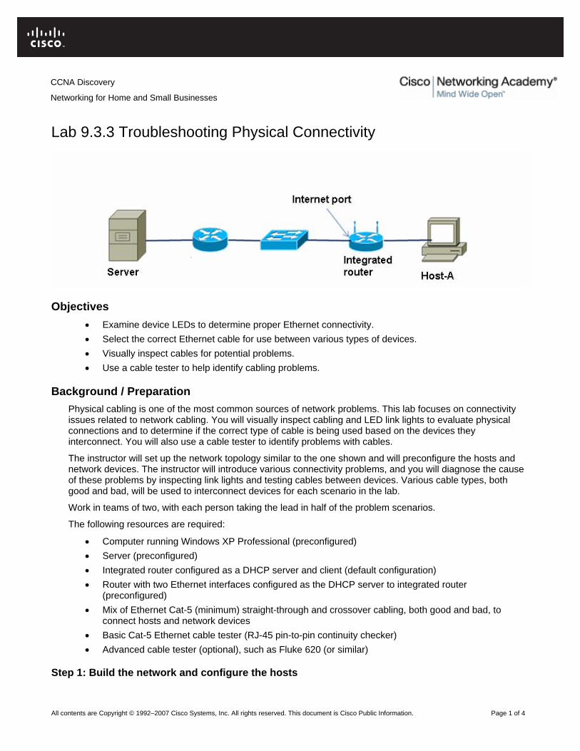
CCNA Discovery
Networking for Home and Small Businesses
Lab 9.3.3 Troubleshooting Physical Connectivity
Objectives • Examine device LEDs to determine proper Ethernet connectivity. • Select the correct Ethernet cable for use between various types of devices. • Visually inspect cables for potential problems. • Use a cable tester to help identify cabling problems.
Background / Preparation Physical cabling is one of the most common sources of network problems. This lab focuses on connectivity issues related to network cabling. You will visually inspect cabling and LED link lights to evaluate physical connections and to determine if the correct type of cable is being used based on the devices they interconnect. You will also use a cable tester to identify problems with cables.
The instructor will set up the network topology similar to the one shown and will preconfigure the hosts and network devices. The instructor will introduce various connectivity problems, and you will diagnose the cause of these problems by inspecting link lights and testing cables between devices. Various cable types, both good and bad, will be used to interconnect devices for each scenario in the lab.
Work in teams of two, with each person taking the lead in half of the problem scenarios.
The following resources are required:
• Computer running Windows XP Professional (preconfigured) • Server (preconfigured) • Integrated router configured as a DHCP server and client (default configuration) • Router with two Ethernet interfaces configured as the DHCP server to integrated router
(preconfigured) • Mix of Ethernet Cat-5 (minimum) straight-through and crossover cabling, both good and bad, to
connect hosts and network devices • Basic Cat-5 Ethernet cable tester (RJ-45 pin-to-pin continuity checker) • Advanced cable tester (optional), such as Fluke 620 (or similar)
Step 1: Build the network and configure the hosts
All contents are Copyright © 1992–2007 Cisco Systems, Inc. All rights reserved. This document is Cisco Public Information. Page 1 of 4

CCNA Discovery
Networking for Home and Small Businesses
a. Ask your instructor to set up a network topology similar to the one shown with a preconfigured Host-A
client computer, integrated router, server, and router. Initially, correct and properly functioning cabling is used so that end-to-end connectivity can be verified. The instructor then introduces cabling problems in each scenario.
b. Problems can consist of using the wrong type of` cable between two devices (straight-through or crossover) or using a defective cable (miswired or improperly terminated). Observe device interface link lights, visually inspect cables, and use a cable tester to determine the problems.
c. Complete steps 2 and 3 of this lab before the instructor introduces problems.
Step 2: Record the correct cable types used between devices a. Refer to the topology diagram and record the cable type that should be used (straight-through or
crossover) based on the devices being connected. Have your instructor verify this information before proceeding.
b. Which type of cable should be used from Host-A to the integrated router? ______________________________
c. Which type of cable should be used from the integrated router (router portion) to Hub/Switch?
____________________________________________________________________________
d. Which type of cable should be used from Hub/Switch to Router? ________________________
e. Which type of cable should be used from Router to Server? ____________________________
Step 3: Record the IP address information for the computers a. Use the ipconfig command, or get the IP address of Host-A from your instructor, and record it here.
Host-A IP address: ____________________________________________________________
b. Get the server IP address from your instructor and record it here.
Server IP address: ____________________________________________________________
c. Before starting on problem scenarios, verify end-to-end connectivity by pinging from Host-A to Server. If you do not get a reply from the server, check with your instructor. There may be a problem with the initial hardware or software setup.
Step 4: Scenario 1 a. After your instructor sets up the problem, use visual inspection and a cable tester to isolate the
problem.
b. Ping from Host-A to Server. What happened?
____________________________________________________________________________
c. Check the LED link lights on the various device interfaces. Write down any that are not lit.
____________________________________________________________________________
d. Disconnect and inspect the cable connecting the network interfaces that were not lit. Describe the problem and how you were able to identify it.
____________________________________________________________________________
____________________________________________________________________________
____________________________________________________________________________
e. What did you do to correct the problem?
____________________________________________________________________________
All contents are Copyright © 1992–2007 Cisco Systems, Inc. All rights reserved. This document is Cisco Public Information. Page 2 of 4

CCNA Discovery
Networking for Home and Small Businesses
f. When the problem is corrected, retest and verify end-to-end connectivity by pinging from Host-A to
Server. Was the ping successful? ________
Step 5: Scenario 2 a. After your instructor sets up the problem, use visual inspection and a cable tester to isolate the
problem.
b. Ping from Host-A to Server. What happened?
____________________________________________________________________________
c. Check the LED link lights on the various device interfaces. Write down any that are not lit.
____________________________________________________________________________
d. Disconnect and inspect the cable connecting the network interfaces that were not lit. Describe the problem and how you were able to identify it.
____________________________________________________________________________
____________________________________________________________________________
____________________________________________________________________________
e. What did you do to correct the problem?
____________________________________________________________________________
f. When the problem is corrected, retest and verify end-to-end connectivity by pinging from Host-A to Server. Was the ping successful? ________
Step 6: Scenario 3 a. After your instructor sets up the problem, use visual inspection and a cable tester to isolate the
problem.
b. Ping from Host-A to Server. What happened?
____________________________________________________________________________
c. Check the LED link lights on the various device interfaces. Write down any that are not lit.
____________________________________________________________________________
d. Disconnect and inspect the cable connecting the network interfaces that were not lit. Describe the problem and how you were able to identify it.
____________________________________________________________________________
____________________________________________________________________________
____________________________________________________________________________
e. What did you do to correct the problem?
____________________________________________________________________________
f. When the problem is corrected, retest and verify end-to-end connectivity by pinging from Host-A to Server. Was the ping successful? ________
Step 7: Scenario 4 a. After your instructor sets up the problem, use visual inspection and a cable tester to isolate the
problem.
b. Ping from Host-A to Server. What happened?
All contents are Copyright © 1992–2007 Cisco Systems, Inc. All rights reserved. This document is Cisco Public Information. Page 3 of 4

CCNA Discovery
Networking for Home and Small Businesses
____________________________________________________________________________
c. Check the LED link lights on the various device interfaces. Write down any that are not lit.
____________________________________________________________________________
d. Disconnect and inspect the cable connecting the network interfaces that were not lit. Describe the problem and how you were able to identify it.
____________________________________________________________________________
____________________________________________________________________________
____________________________________________________________________________
e. What did you do to correct the problem?
____________________________________________________________________________
f. When the problem is corrected, retest and verify end-to-end connectivity by pinging from Host-A to Server. Was the ping successful? ________
Step 8: Reflection a. What are some general rules to help you determine which type of Ethernet cable (straight-through or
crossover) to use to connect different types of network hosts and devices?
____________________________________________________________________________
____________________________________________________________________________
____________________________________________________________________________
b. Which types of problems can a cable tester detect that might not be determined by visual inspection?
____________________________________________________________________________
All contents are Copyright © 1992–2007 Cisco Systems, Inc. All rights reserved. This document is Cisco Public Information. Page 4 of 4

CCNA Discovery
Networking for Home and Small Businesses
Capstone Project – Putting It All Together
Objectives • Understand the steps involved in planning and implementing a technical solution for a small business. • Gather relevant information to help devise a technical solution to a problem. • Devise a technical solution for a small office environment. • Prototype a proposed technical solution using Packet Tracer 4.1. • Plan the installation of a technical solution for a small business environment. • Prepare and present a technical report to a diverse group. • Configure a wireless router to support the requirements of a small business environment.
Background / Preparation You have just successfully completed the first course in the CCNA-Discovery series and have obtained a contract position at a small advertising company called AnyCompany Corporation to help them update their IT resources. The company originally started with two partners who produced print flyers for local businesses. Their list of customers has greatly expanded, and their customers are demanding more interactive advertising media, including video presentations. The partners recognize the business potential in this new market and have hired you to review their existing IT resources and produce a proposal that allows the company to take advantage of this new market. The partners have stated that if the proposal meets their requirements, they may hire you full-time to implement and manage these new resources.
Step 1: Gather information and determine customer requirements You now have an idea of the scope of the project that you have undertaken, but do not have all of the information required to proceed. The first step in any IT project is to gather information. What is really required? What are the budget and the time frame to complete this project? What restrictions, if any, are there in equipment and resource selection? What resources are currently in place? The more information that you gather at the beginning of any project, the better. A good way to start the information gathering process is to conduct interviews with the key individuals within the company, who are usually divided into three main groups: managers, end users, and IT support. Each group can provide valuable information. Managers – Managers can answer questions regarding budget, expectations, and future plans. Any IT solution must take into account the plans that the company may have for growth, either in the number of employees or the technology being deployed. Managers can also provide you with information regarding company policies that may affect the proposed solution. Policies could include such things as access, security, and privacy requirements. The following information is normally gathered from managers:
• Budget • Requirements and expectations • Restrictions • Staffing • Future growth
All contents are Copyright © 1992–2007 Cisco Systems, Inc. All rights reserved. This document is Cisco Public Information. Page 1 of 9
CCNA Discovery
Networking for Home and Small Businesses v4.0: Putting It All Together
End users – End users are the people directly impacted by the solution you design. While managers are also end users, their requirements may differ drastically from the majority of the employees. It is important to talk to as many employees from as many departments or work areas as possible to determine their requirements. It is also important to determine the actual, rather than perceived, requirements. From a customer service perspective, including employees in the initial discussions improves their buy-in and acceptance of the final solution. The following information is normally gathered from end users:
• Requirements and expectations • Current perceived performance of the equipment • Applications used • Work patterns
IT department – Most small businesses do not have an IT department and responsibilities may fall on one or more individuals, depending on their job role and expertise. Larger businesses may have a separate IT department. Those individuals who handle the IT can provide you with more technical information. For example, an end user may complain that an existing network has become slow, but an IT person can provide the technical information to determine if performance has been degraded. The following information is normally gathered from IT:
• Applications used • Work patterns • Hardware resources • Network infrastructure (physical and logical topology) • Network performance and issues
Activity 1 AnyCompany Corporation has provided a written summary containing a floor plan, and a verbal interview with a company manager. Gather as much information as possible from these two sources to help you plan a technical solution for AnyCompany Corporation. AnyCompany Corporation Information
Because AnyCompany Corporation is a very small business, it has no IT department. Everyone has taken care of their own resources. If they could not fix the problem, they would call in an outside service technician. The machines are connected together through a 10 Mbps hub using Category 3 cable. The two partners and the secretary all have P2-300 MHz machines with 256 MB of RAM and 13 GB hard disk drives. The systems are all running Windows 98SE, and each a low-capacity, monochrome laser printer is attached to each machine. These machines are not capable of running the software required for video development. The office will be reorganized, and additional employees will be hired to handle the new video production work. The company will have the following employees: Administrative Manager (currently the secretary) – Duties include scheduling work, hiring and managing part-time workers, weekly payroll, and project tracking. The administrative manager uses spreadsheet and database software and must be able to use e-mail provided by the ISP. Film and Graphics Production Editor (one of the partners) – Requires special editing software that uses very high-resolution graphics and requires at least 2 GB of memory to run effectively. The software also interfaces with a video capture interface board that uses a PCI slot in the computer. This specialized software only works in a Windows XP environment. It is important that the computer purchased for this position support high-resolution video and have enough memory to enable the editor to work quickly. The
All contents are Copyright © 1992–2007 Cisco Systems, Inc. All rights reserved. This document is Cisco Public Information. Page 2 of 9

CCNA Discovery
Networking for Home and Small Businesses v4.0: Putting It All Together
production editor produces the final copies of the films and works within very tight deadlines. The editor must also be able to use e-mail provided by the ISP. Film Crew – The other six employees are mobile workers, consisting of two production assistants, two camera people, a production manager (one of the partners), and a film director. They are in the office an average of two days per week. The rest of the time is spent either at customer sites or on film locations. Because all of the mobile workers are required to have access to e-mail and production schedules, both at the office and while on location, it is important for them to be able to connect to the main office from anywhere. They have no special software requirements, but they do need a large hard drive to store the film files while they are working on them. The mobile workers must work at various locations and may not always be able to plug into a data port. It is important that they are able to connect to the internal network wirelessly. Because of the sensitive nature of some of the documents and records required by the administrative manager, a private color laser printer must be installed in the manager’s office. A combination copier/printer and high-resolution scanner must also be purchased and shared among all employees. For the purposes of training and compatibility, all of the computers should use the same operating system and applications, if possible. No budget has yet been established for the completion of this project. The company is moving into this area to prevent bankruptcy, so it is important that the project be completed with the lowest possible expenditures.
All contents are Copyright © 1992–2007 Cisco Systems, Inc. All rights reserved. This document is Cisco Public Information. Page 3 of 9

CCNA Discovery
Networking for Home and Small Businesses v4.0: Putting It All Together
Office Floor Plan
Interview with the Administrative Manager
Susan Roberts: I am the new administrative manager for AnyCompany Corporation. I am very glad that we have hired you to help us plan our IT requirements and would like to discuss these with you. I understand that you have already been supplied with a list of our planned staff and some information about how they use their computers. I have some details that might be important as you select equipment and media for our new facilities. You: It is nice to meet you, Susan. Yes, I received a letter that listed the numbers and types of employees working at the redesigned office. It is my understanding that there will be eight employees: two office employees and six mobile workers. Any information you can provide about how these workers will use the network can help me prepare the proposal for your local network. Roberts: Both Fred Michaels, the film and graphics production editor, and I are in our offices during regular business hours. We need access to e-mail, which we currently get from our ISP. The e-mail system that they provide uses a web client that we can access over the Internet. We are also able to access this e-mail from our home computers It is necessary for both of us to share files between ourselves and also with the mobile workers. These files are usually spreadsheets and documents, but sometimes, when we are close to deadlines, we have to send large film files back and forth between the mobile workers and the office. Files must be available
All contents are Copyright © 1992–2007 Cisco Systems, Inc. All rights reserved. This document is Cisco Public Information. Page 4 of 9
CCNA Discovery
Networking for Home and Small Businesses v4.0: Putting It All Together
for download during the day, and also at night, when we are away from the office. These film files are usually between 512 MB and 2 GB in size. You: The information I received also indicated that you require a shared printer. How do you plan on using this printer? Roberts: We want to have a color printer that is also capable of making copies. Since we expect this printer to be expensive, it is necessary for everyone to be able to print to it when they are in the office. Some of our storyboard documents are over 100 pages, with lots of graphics. You: How often are the mobile workers in the office? What do they need access to when they are in the office? Roberts: Our mobile workers can be in the office anytime, day or night. They usually work out of their homes or on location, but when we are near a deadline, they can be in the office for 24 hours at a time. When they are in the office, they need to be able to use the printer and scanner. I do not want to keep files that the mobile workers need to use on my computer, because they might need them at times when I am not in the office, and the computer is not turned on. I also need to share files with Fred while we are working in the office. These files can be kept on my computer or his. You: I understand that your e-mail accounts are provided over the web by your ISP. Do you see a need for locally hosted web or e-mail accounts? Roberts: We also employ temporary, part-time employees when we need them. We want to be able to set up e-mail accounts for them to use while they are working with us. We usually don’t have more than five or six temporary employees at any one time. All of them work from their homes and use their own computers. You: Thank you for your time. I think I have enough information to get started. Are you the contact person if I have any further questions? Roberts: Yes, please call me if you need more information. Thank you.
At this point, it is a good idea to review the notes and information that you have gathered and clearly summarize the requirements. If something is not clear, go back to the information-gathering step. Do not guess or assume anything, because mistakes can be very costly.
Step 2: Select the appropriate services and equipment Once you have gathered all the appropriate information, it is time to do some research. You must now use your knowledge and research skills to propose an appropriate technical solution for their limited budget and time requirements. Proposing a solution that is beyond the financial capabilities is of no benefit. However, it can be helpful to propose a solution within the current budget, and offer suggestions that would improve network performance or productivity if additional funding becomes available. If you can justify these extra expenditures, the company may consider them for later implementation or may even find the extra funding needed. When developing a plan, it is often easier to start at the end user and then work back toward the network and any shared resources, and then finally, any external connections to the Internet or other networks. Many different forms have been developed to help with planning and equipment selection. It is a good idea to use one of these forms or to design your own to keep everything organized.
All contents are Copyright © 1992–2007 Cisco Systems, Inc. All rights reserved. This document is Cisco Public Information. Page 5 of 9

CCNA Discovery
Networking for Home and Small Businesses v4.0: Putting It All Together
Activity 2 Use the following form to develop a proposed computer system for each of the employees at AnyCompany Corporation. Search the Internet or local sources for availability and pricing information. Use the same form to propose a server that can support their e-mail and FTP requirements.
Computer System Planning Form Job Role:
Location:
Component Recommendation
Processor: (manufacturer/model/speed)
Memory: (type, amount)
Hard Drive: (type, capacity)
CD-ROM/DVD: (R, R/W, speed)
USB Ports: (number, location)
Video Card: (manufacturer, model, video RAM)
Sound Card: (manufacture, model)
Modem (internal/external, speed, standard)
Network Card(s): (Ethernet: speed, wireless, standard)
Operating System: (manufacturer, version, compatibility)
Monitor: (size, resolution, refresh)
Printer: (manufacturer, model, type, speed)
Speakers: (manufacturer, model, type)
Internet connection: (USB/Ethernet/wireless)
After the end-user systems have been selected, it is time to look at the workflow and decide on any shared components and network technology to support this workflow. This can include such things as shared printers, scanners, and storage as well as any routers, switches, access points and ISRs. When planning a network infrastructure, always plan into the future. For larger companies, because it is usually a substantial investment, the infrastructure should have a lifetime of about 10 years. For smaller companies and home users, the investment is significantly less and change occurs more frequently.
All contents are Copyright © 1992–2007 Cisco Systems, Inc. All rights reserved. This document is Cisco Public Information. Page 6 of 9

CCNA Discovery
Networking for Home and Small Businesses v4.0: Putting It All Together
Activity 3 Using the Internet and locally available resources, select a high-speed, color copier/printer for the AnyCompany Corporation office. Activity 4 Propose a network layout for AnyCompany Corporation. Because the company has limited funds available for this project, it is important that only equipment designed for the small business and home markets be used. It is important to plan the Internet connectivity, and which services are provided by the ISP and which services must be provided in-house. Larger companies usually provide services in-house while small businesses and individuals normally rely on an ISP to provide these services. Most ISPs offer a variety of services and service levels. Selecting an ISP is complicated, and not all technologies and services are available in all regions of the world. There are a number of excellent online tools to assist in the selection process. One such tool has been produced by the Australian government and is available at http://toolkit.acma.gov.au/internet/form.asp. Activity 5 Using the curriculum and other available resources, select a local ISP to provide connectivity for AnyCompany Corporation. It will rely upon this ISP for DNS and web mail, and also needs the ISP to provide 99.999% uptime for access to the internal FTP/e-mail server. Because you are the only IT person at AnyCompany Corporation, it is also important that the ISP provides a high-level of technical support. Create a comparison worksheet for several local ISPs, including costing. Activity 6 Which internal services must be offered by AnyCompany Corporation, and which devices provide these services? Activity 7 Complete the following network planning form as it relates to the proposed AnyCompany Corporation network.
Are wired connections required? Number: Are wireless connections required? Number: Wireless standard Choice of a/b/g/n Firewall required? Yes/No ISP connectivity required? Yes/No Type of ISP connectivity Choice of DSL, cable, serial, dialup Internal or external modem required? Yes/No (if Yes, then type of modem) Cables required? Yes/No (if Yes, then type of cable) Battery backup required? Yes/No
Step 3: Plan the installation After the equipment has been selected and the required services planned, the physical and logical installation is planned out. Physical installation includes the location of equipment and devices, along with how and when these devices are to be installed. In the business environment, it is important to minimize disruption of the normal work processes. Therefore, most installations, changes, and upgrades are done during hours when there is minimal business activity. For the home, this is less important but should still be considered. Physical installation should also consider such things as adequate power outlets and ventilation, as well as the location of any necessary data drops. Activity 8 Using the provided floor plan and other appropriate information, plan the physical layout of all equipment data drops and power outlets. In addition, devise an implementation schedule that takes into account the work practices within AnyCompany Corporation.
All contents are Copyright © 1992–2007 Cisco Systems, Inc. All rights reserved. This document is Cisco Public Information. Page 7 of 9

CCNA Discovery
Networking for Home and Small Businesses v4.0: Putting It All Together
Equally as important as planning the physical layout of the network and equipment is planning the logical layout. This includes such things as addressing, naming, data flow, and security measures. Servers and network devices are assigned static IP addresses to allow them to be easily identified on the network and to also provide a mechanism for controlling access to these devices. Most other devices can be assigned addresses using DHCP. Activity 9 Devise an addressing scheme for AnyCompany Corporation. The scheme must provide all network devices and servers with a static address and allow all other hosts to be configured via DHCP. Assign all devices an appropriate name. Activity 10 AnyCompany Corporation is concerned that their files and resources may be vulnerable through the wireless network. Provide a security plan that allows only AnyCompany Corporation employees to connect to the wireless network and gain access to company information and resources. After the network is planned, it is important to verify that it works as expected. This is the prototyping stage and is not normally done for home or small business installations. Many different prototyping tools exist in the enterprise world. Activity 11 Use Packet Tracer to prototype the planned network. Test various scenarios such as traffic coming from the Internet to the internal servers and host traffic moving to the Internet. Also confirm that the wireless network behaves as expected. Not all features of the designed network will be able to be tested using Packet Tracer.
Step 4: Prepare and present the proposal All of the gathered information and the proposed technical solution must be assembled into a format that makes sense to the company or individual who has asked you to provide a solution. In the small business and home markets, this may be simply a summary report that lists the key points in a manner that is easily understood. In the enterprise market, this process becomes much more structured and formal. The formal report usually contains many different sections, including:
• Cover letter • Title page and table of contents • Executive summary • Project proposal, comprising needs statement; goals and objectives; methodology and timetable;
evaluation; budget summary; detailed budget; future funding plans • Appended information
The report is often presented to various groups for approval. When presenting the report, present it in a confident, professional, and enthusiastic manner. This includes dressing appropriate to the target audience. The report and presentation must be technically accurate and free from spelling and grammatical errors. Always proof read your report and presentation before delivery. Have it reviewed by peers as well. A good technical solution does not overcome a bad proposal or presentation. Activity 12 Prepare a proposal for AnyCompany Corporation that includes all the components listed above. Be sure to include all cost information and network diagrams. After the report is prepared, have it reviewed by a peer. When you are confident in the proposal, present it to the class for consideration.
All contents are Copyright © 1992–2007 Cisco Systems, Inc. All rights reserved. This document is Cisco Public Information. Page 8 of 9
CCNA Discovery
Networking for Home and Small Businesses v4.0: Putting It All Together
Step 5: Install and configure the network After the proposal has been accepted by the individual or company, it is time to do the installation. This is another stage where planning is important. If devices can be preconfigured and tested before installation, it saves a great deal of time and frustration. Activity 13 AnyCompany Corporation has decided to accept your proposal for the installation of their new network. All of the recommended equipment is on order and scheduled for delivery within a month.
1) Create a checklist for the installation of the PCs at the customer site. 2) Create a checklist for the configuration and installation of the network equipment at the customer site. 3) Create a checklist for the implementation of the standard security necessary at a small business.
Activity 14 Configure the ISR as per the proposed plan.
Step 6: Test and troubleshoot During the installation, it is important to test the network under as many diverse situations as possible. Use the various troubleshooting tools available in most operating systems and network devices to ensure that the network behaves as expected under the normal workflow that it will be exposed to. Document all tests. Activity 15 Test all aspects of the ISR configuration and document your results.
Step 7: Document and sign-off Sign-off is when the customer indicates satisfaction that the solution performs as promised. This is usually the point that payment is made. Many internal IT departments also request sign-off when a job is completed to the end user satisfaction. When sign-off occurs, printed copies of the performance and testing reports are delivered, along with the configuration information. For larger networks, much more information is required at sign-off, including physical and logical topology maps. Activity 16 Prepare documentation for sign-off from the manager at AnyCompany Corporation. This includes the testing and performance documentation generated, along with any other prepared documentation. Have this information reviewed by a peer and then submit it to your instructor for final sign-off.
Step 8: Support The last step in any solution is the provision of ongoing technical support. This requires a thorough understanding of the solution, technology, and customer requirements. The more thorough the documentation, the easier this stage is. Equally as important at this stage is an excellent grasp of customer service skills. Activity 17 Take turns playing the technical support and customer roles. The customer contacts the technical support person and reports a problem with the newly implemented AnyCompany Corporation network. The problem should be realistic. The support person tries to determine the problem by interacting with the customer.
All contents are Copyright © 1992–2007 Cisco Systems, Inc. All rights reserved. This document is Cisco Public Information. Page 9 of 9