
en ACS800 Adaptive Program Application Guide · Note: The parameter selected as an input should be...
44
ABB Drives Application Guide Adaptive Program
Transcript of en ACS800 Adaptive Program Application Guide · Note: The parameter selected as an input should be...

ABB Drives
Application GuideAdaptive Program


Adaptive Program
3AFE64527274 Rev C EN
EFFECTIVE: 08.04.2005
Application Guide
© 2005 ABB Oy. All Rights Reserved.

5
Table of Contents
Table of Contents
Introduction to the guide
Chapter overview . . . . . . . . . . . . . . . . . . . . . . . . . . . . . . . . . . . . . . . . . . . . . . . . . . . . . . . . . . . . . . . 7Compatibility . . . . . . . . . . . . . . . . . . . . . . . . . . . . . . . . . . . . . . . . . . . . . . . . . . . . . . . . . . . . . . . . . . . 7Safety instructions . . . . . . . . . . . . . . . . . . . . . . . . . . . . . . . . . . . . . . . . . . . . . . . . . . . . . . . . . . . . . . . 7Reader . . . . . . . . . . . . . . . . . . . . . . . . . . . . . . . . . . . . . . . . . . . . . . . . . . . . . . . . . . . . . . . . . . . . . . . . 7Use . . . . . . . . . . . . . . . . . . . . . . . . . . . . . . . . . . . . . . . . . . . . . . . . . . . . . . . . . . . . . . . . . . . . . . . . . . 7Related publications . . . . . . . . . . . . . . . . . . . . . . . . . . . . . . . . . . . . . . . . . . . . . . . . . . . . . . . . . . . . . 8
Adaptive Program
Chapter overview . . . . . . . . . . . . . . . . . . . . . . . . . . . . . . . . . . . . . . . . . . . . . . . . . . . . . . . . . . . . . . . 9What is the Adaptive Program . . . . . . . . . . . . . . . . . . . . . . . . . . . . . . . . . . . . . . . . . . . . . . . . . . . . . . 9How to build the program . . . . . . . . . . . . . . . . . . . . . . . . . . . . . . . . . . . . . . . . . . . . . . . . . . . . . . . . 10How to connect the program to the drive application . . . . . . . . . . . . . . . . . . . . . . . . . . . . . . . . . . . 11How to control the execution of the program . . . . . . . . . . . . . . . . . . . . . . . . . . . . . . . . . . . . . . . . . . 11
Function blocks
Chapter overview . . . . . . . . . . . . . . . . . . . . . . . . . . . . . . . . . . . . . . . . . . . . . . . . . . . . . . . . . . . . . . 13General rules . . . . . . . . . . . . . . . . . . . . . . . . . . . . . . . . . . . . . . . . . . . . . . . . . . . . . . . . . . . . . . . . . . 13Block inputs . . . . . . . . . . . . . . . . . . . . . . . . . . . . . . . . . . . . . . . . . . . . . . . . . . . . . . . . . . . . . . . . . . . 13
Parameter value as an integer input . . . . . . . . . . . . . . . . . . . . . . . . . . . . . . . . . . . . . . . . . . . . . . 14How the block handles the input . . . . . . . . . . . . . . . . . . . . . . . . . . . . . . . . . . . . . . . . . . . . . . 14How to select the input . . . . . . . . . . . . . . . . . . . . . . . . . . . . . . . . . . . . . . . . . . . . . . . . . . . . . . 14
Constant as an integer input . . . . . . . . . . . . . . . . . . . . . . . . . . . . . . . . . . . . . . . . . . . . . . . . . . . . 15How to set and connect the input . . . . . . . . . . . . . . . . . . . . . . . . . . . . . . . . . . . . . . . . . . . . . . 15
Parameter value as a boolean input . . . . . . . . . . . . . . . . . . . . . . . . . . . . . . . . . . . . . . . . . . . . . . 16How the block handles the input . . . . . . . . . . . . . . . . . . . . . . . . . . . . . . . . . . . . . . . . . . . . . . 16How to select the input . . . . . . . . . . . . . . . . . . . . . . . . . . . . . . . . . . . . . . . . . . . . . . . . . . . . . . 16
Constant as a boolean input . . . . . . . . . . . . . . . . . . . . . . . . . . . . . . . . . . . . . . . . . . . . . . . . . . . . 17How to set and connect the input . . . . . . . . . . . . . . . . . . . . . . . . . . . . . . . . . . . . . . . . . . . . . . 17
String input . . . . . . . . . . . . . . . . . . . . . . . . . . . . . . . . . . . . . . . . . . . . . . . . . . . . . . . . . . . . . . . . . 17How to select the input . . . . . . . . . . . . . . . . . . . . . . . . . . . . . . . . . . . . . . . . . . . . . . . . . . . . . . 17
Function blocks . . . . . . . . . . . . . . . . . . . . . . . . . . . . . . . . . . . . . . . . . . . . . . . . . . . . . . . . . . . . . . . . 18ABS . . . . . . . . . . . . . . . . . . . . . . . . . . . . . . . . . . . . . . . . . . . . . . . . . . . . . . . . . . . . . . . . . . . . . . . . . 18ADD . . . . . . . . . . . . . . . . . . . . . . . . . . . . . . . . . . . . . . . . . . . . . . . . . . . . . . . . . . . . . . . . . . . . . . . . . 18AND . . . . . . . . . . . . . . . . . . . . . . . . . . . . . . . . . . . . . . . . . . . . . . . . . . . . . . . . . . . . . . . . . . . . . . . . . 18BITWISE . . . . . . . . . . . . . . . . . . . . . . . . . . . . . . . . . . . . . . . . . . . . . . . . . . . . . . . . . . . . . . . . . . . . . 19COMPARE . . . . . . . . . . . . . . . . . . . . . . . . . . . . . . . . . . . . . . . . . . . . . . . . . . . . . . . . . . . . . . . . . . . 19COUNT . . . . . . . . . . . . . . . . . . . . . . . . . . . . . . . . . . . . . . . . . . . . . . . . . . . . . . . . . . . . . . . . . . . . . . 20DPOT . . . . . . . . . . . . . . . . . . . . . . . . . . . . . . . . . . . . . . . . . . . . . . . . . . . . . . . . . . . . . . . . . . . . . . . 21
Table of Contents
6
EVENT . . . . . . . . . . . . . . . . . . . . . . . . . . . . . . . . . . . . . . . . . . . . . . . . . . . . . . . . . . . . . . . . . . . . . . 21FILTER . . . . . . . . . . . . . . . . . . . . . . . . . . . . . . . . . . . . . . . . . . . . . . . . . . . . . . . . . . . . . . . . . . . . . . 21MASK-SET . . . . . . . . . . . . . . . . . . . . . . . . . . . . . . . . . . . . . . . . . . . . . . . . . . . . . . . . . . . . . . . . . . . 22MAX . . . . . . . . . . . . . . . . . . . . . . . . . . . . . . . . . . . . . . . . . . . . . . . . . . . . . . . . . . . . . . . . . . . . . . . . 22MIN . . . . . . . . . . . . . . . . . . . . . . . . . . . . . . . . . . . . . . . . . . . . . . . . . . . . . . . . . . . . . . . . . . . . . . . . . 23MULDIV . . . . . . . . . . . . . . . . . . . . . . . . . . . . . . . . . . . . . . . . . . . . . . . . . . . . . . . . . . . . . . . . . . . . . 23NO . . . . . . . . . . . . . . . . . . . . . . . . . . . . . . . . . . . . . . . . . . . . . . . . . . . . . . . . . . . . . . . . . . . . . . . . . 23OR . . . . . . . . . . . . . . . . . . . . . . . . . . . . . . . . . . . . . . . . . . . . . . . . . . . . . . . . . . . . . . . . . . . . . . . . . 23PI . . . . . . . . . . . . . . . . . . . . . . . . . . . . . . . . . . . . . . . . . . . . . . . . . . . . . . . . . . . . . . . . . . . . . . . . . . 24PI-BAL . . . . . . . . . . . . . . . . . . . . . . . . . . . . . . . . . . . . . . . . . . . . . . . . . . . . . . . . . . . . . . . . . . . . . . 24PI-BIPOLAR . . . . . . . . . . . . . . . . . . . . . . . . . . . . . . . . . . . . . . . . . . . . . . . . . . . . . . . . . . . . . . . . . . 25RAMP . . . . . . . . . . . . . . . . . . . . . . . . . . . . . . . . . . . . . . . . . . . . . . . . . . . . . . . . . . . . . . . . . . . . . . . 25SR . . . . . . . . . . . . . . . . . . . . . . . . . . . . . . . . . . . . . . . . . . . . . . . . . . . . . . . . . . . . . . . . . . . . . . . . . 27SWITCH-B . . . . . . . . . . . . . . . . . . . . . . . . . . . . . . . . . . . . . . . . . . . . . . . . . . . . . . . . . . . . . . . . . . . 27SWITCH-I . . . . . . . . . . . . . . . . . . . . . . . . . . . . . . . . . . . . . . . . . . . . . . . . . . . . . . . . . . . . . . . . . . . . 28TOFF . . . . . . . . . . . . . . . . . . . . . . . . . . . . . . . . . . . . . . . . . . . . . . . . . . . . . . . . . . . . . . . . . . . . . . . 28TON . . . . . . . . . . . . . . . . . . . . . . . . . . . . . . . . . . . . . . . . . . . . . . . . . . . . . . . . . . . . . . . . . . . . . . . . 29TRIGG . . . . . . . . . . . . . . . . . . . . . . . . . . . . . . . . . . . . . . . . . . . . . . . . . . . . . . . . . . . . . . . . . . . . . . 29XOR . . . . . . . . . . . . . . . . . . . . . . . . . . . . . . . . . . . . . . . . . . . . . . . . . . . . . . . . . . . . . . . . . . . . . . . . 30
Actual signals and parameters in ACS800 Standard Application Program
Chapter overview . . . . . . . . . . . . . . . . . . . . . . . . . . . . . . . . . . . . . . . . . . . . . . . . . . . . . . . . . . . . . . 31Actual signals . . . . . . . . . . . . . . . . . . . . . . . . . . . . . . . . . . . . . . . . . . . . . . . . . . . . . . . . . . . . . . . . . 31Parameters . . . . . . . . . . . . . . . . . . . . . . . . . . . . . . . . . . . . . . . . . . . . . . . . . . . . . . . . . . . . . . . . . . . 32
Customer diagrams
Chapter overview . . . . . . . . . . . . . . . . . . . . . . . . . . . . . . . . . . . . . . . . . . . . . . . . . . . . . . . . . . . . . . 39
Table of Contents
7
Introduction to the guide
Chapter overviewThe chapter gives general information on the guide.
CompatibilityThe guide complies with the drive application programs in which the Adaptive Programming features are included.
Safety instructionsFollow all safety instructions delivered with the drive.
� Read the complete safety instructions before you install, commission or use the drive. The complete safety instructions are given at the beginning of the Hardware Manual.
� Read the software function specific warnings and notes before changing the default settings of the function. For each function, the warnings and notes are given in the Firmware Manual in the subsection describing the related user-adjustable parameters.
ReaderThe reader of the manual is expected to:
� know the standard electrical wiring practices, electronic components and electrical schematic symbols.
� have no experience or training in installing, operating or servicing of ABB drives.
UseThe guide is to be used together with the firmware manual of the drive application program. The firmware manual contains the basic information on the drive parameters including the parameters of the Adaptive Program. The guide gives more detailed information on the Adaptive Program:
� what the Adaptive Program is
� how to build a program
� how the function blocks operate
� how to document the program
� the parameters and actual signals of ACS800 Standard Application Program essential for the Adaptive Program.
Introduction to the guide

8
Related publicationsThe user documentation of the drive also includes:
� Firmware manual (the appropriate manual is delivered with the unit)
� Hardware manual (the appropriate manual is delivered with the unit)
� Guides/supplements for the optional equipment and programs (appropriate manuals are included in the delivery).
Introduction to the guide

9
Adaptive Program
Chapter overviewThe chapter describes the basics of the Adaptive Program and instructs in building a program.
What is the Adaptive ProgramConventionally, the user can control the operation of the drive by parameters. Each parameter has a fixed set of choices or a setting range. The parameters make the programming easy, but the choices are limited: you cannot customise the operation any further. The Adaptive Program makes freer customising possible without the need of a special programming tool or language:
� The program is built of function blocks.
� The control panel is the programming tool.
� The user can document the program by drawing it on block diagram template sheets.
The maximum size of the Adaptive Program is 15 function blocks. The program may consist of several separate functions.
Adaptive Program
10
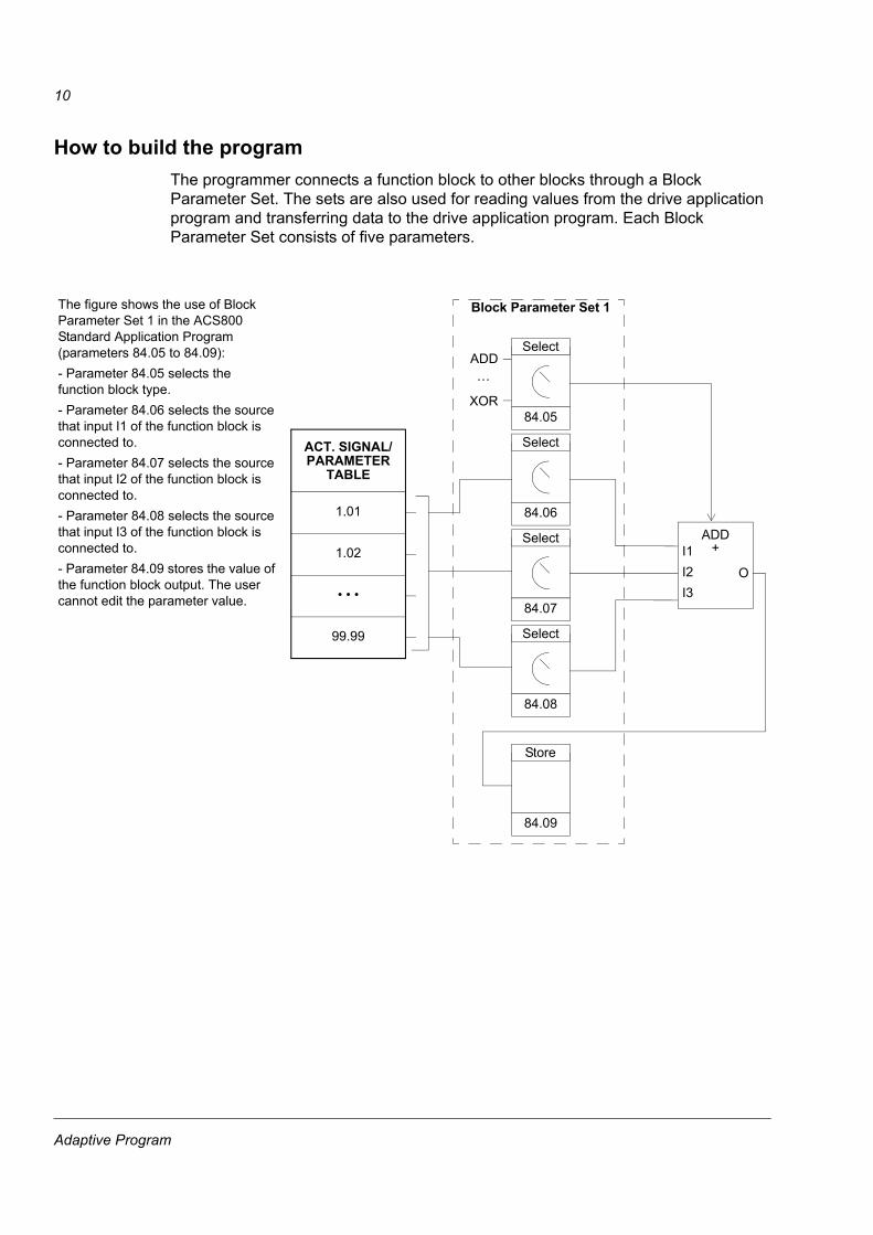
How to build the programThe programmer connects a function block to other blocks through a Block Parameter Set. The sets are also used for reading values from the drive application program and transferring data to the drive application program. Each Block Parameter Set consists of five parameters.
Block Parameter Set 1
84.05
Select
84.06
Select
84.07
Select
84.08
Select
84.09
Store
ACT. SIGNAL/
1.01
1.02
� � �
99.99
PARAMETERTABLE
ADD
XOR
�
I1I2I3
ADD+
O
The figure shows the use of Block Parameter Set 1 in the ACS800 Standard Application Program (parameters 84.05 to 84.09):- Parameter 84.05 selects the function block type.- Parameter 84.06 selects the source that input I1 of the function block is connected to.- Parameter 84.07 selects the source that input I2 of the function block is connected to.- Parameter 84.08 selects the source that input I3 of the function block is connected to.- Parameter 84.09 stores the value of the function block output. The user cannot edit the parameter value.
Adaptive Program

11
How to connect the program to the drive applicationThe output of the Adaptive Program needs to be connected to the drive application program. For that purpose the user needs two parameters:
� a connection parameter and
� a source selection parameter (pointer).
The figure below shows the connection principle.
How to control the execution of the programThe Adaptive Program executes the function blocks in numerical order, all blocks on the same time level. This cannot be changed by the user. The user can:
� select the operation mode of the program (stop, start, editing)
� adjust the execution time level of the program
� delete or add blocks.
Example: The Adaptive Program output is stored in parameter 84.09. The diagram shows how to use the value as speed reference REF1 in the ACS800 Standard Application Program.
11.10
Select
ACT. SIGNAL/
1.01
1.02
� � �
99.99
PARAMETERTABLE
84.09
� � �
11.03
Select
Speed Reference
AI1AI2�
Connection parameter
Source selection parameter (pointer)
EXT1REF PTR8409
Adaptive Program

12
Adaptive Program
13
Function blocks
Chapter overviewThe chapter describes the function blocks.
General rulesThe use of input I1 is compulsory (it must not be left unconnected). Use of input I2, I3, etc. is voluntary for the most blocks. As a rule of thumb, a unconnected input does not affect the output of the block.
Block inputsThe blocks use three input formats:
� integer
� boolean
� text string
The used format varies depending on the block. For example, the ADD block uses integer inputs and the OR block boolean inputs. Text string format is used only by the EVENT block.
Note: The inputs of the block are read when the execution of the block starts, not simultaneously for all blocks!
Function blocks

14
Parameter value as an integer inputHow the block handles the input
The block reads the selected value in as an integer.
Note: The parameter selected as an input should be a real or integer value. If the value is not in integer format by default, the block converts it. The integer (fieldbus) scaling for each parameter is given in the Firmware Manual.
How to select the input
� Scroll to the input selection parameter of the block and switch to edit mode (Enter).
� Set the values of the inversion, group, index and bit fields according to the address from which the input value is to be read (double arrow and arrow keys).
The figure below shows the panel display when the input I1 selection parameter is in edit mode. The value is inverted if there is a minus ( - ) sign in the inversion field. The bit selection field is not effective for an integer or string type input.
Example: Analogue input AI1 is 5.8 V in a drive equipped with the ACS800 Standard Application Program. How is the signal connected to the MAX block in the Adaptive Program? What is the value at the block input?
AI1 is connected to the block as follows:
� Scroll to the input I1 selection parameter and shift to edit mode (Enter).
� Set the value in the group field to 1 and the value in the index field to 18. (Value of AI1 is internally stored as actual signal 1.18.)
The value at the input of the block is 5800, since the integer scaling of actual signal 1.18 is: 0.001 V = 1 (given in the Firmware Manual).
1 L -> 0 rpm 084 ADAPTIVE PROGRAM06 INPUT1[±001.018.00]
Inversion field Group field Index field
Bit field
Display of the panel
Function blocks

15
Constant as an integer inputHow to set and connect the input
Option 1
� Scroll to the input selection parameter of the block and switch to edit mode (Enter).
� Select C in the inversion field (double arrow and arrow keys). The appearance of the row changes. The rest of the line is now a constant field.
� Give the constant value to the constant field (double arrow and arrow keys).
� Accept by Enter.
The figure below shows the panel display when the input I1 selection parameter is in edit mode and the constant field is visible. The constant may have a value from -32768 to 32767. The constant cannot be changed while the adaptive program is running.
Option 2
� Set the constant to one of the parameters reserved for the constants.
� Connect the constant value to a block as usual by the input selection parameter.
The constants can be changed while the adaptive program is running. They may have values from �8388608�8388607.
1 L -> 0 rpm 084 ADAPTIVE PROGRAM06 INPUT1[C.-10000]
Inversion (constant) fieldConstant setting field
Display of the panel
Function blocks

16
Parameter value as a boolean inputHow the block handles the input
� The block reads the selected value as an integer.
� The block uses the bit defined by the bit field as the boolean input.
Bit value 1 is boolean value true and 0 is boolean value false.
Example: The figure below shows the value of input I1 selection parameter when the input is connected to a bit indicating the status of digital input DI2. (In ACS800 Standard Application Program, the digital input states are internally stored as actual signal 1.17 DI6-1 STATUS. Bit 1 corresponds to DI2, bit 0 to DI1.)
How to select the input
See the section Parameter value as an integer input above.
Note: The parameter selected as an input should have a packed boolean value (binary data word). See the Firmware Manual.
1 L -> 0 rpm 084 ADAPTIVE PROGRAM06 INPUT1[±001.017.01]
Inversion fieldGroup fieldIndex field
Bit field
Display of the panel
Function blocks

17
Constant as a boolean inputHow to set and connect the input
� Scroll to the input selection parameter of the block and switch to edit mode (Enter).
� Select C in the inversion field (double arrow and arrow keys). The rest of the line changes to a constant setting field.
� Give the constant. If boolean value true is needed, set the constant to -1. If boolean value false is needed, set to 0.
� Accept by Enter.
String inputHow to select the input
String input is needed only with the EVENT block.
For the input selection procedure, see the section Parameter value as an integer input above. The bit selection field is not effective.
Note: The parameter selected as an input must have a string value. In the ACS800 Standard Application Program, there are parameters in group 85 USER CONSTANTS which can be used for string inputs.
Function blocks
18
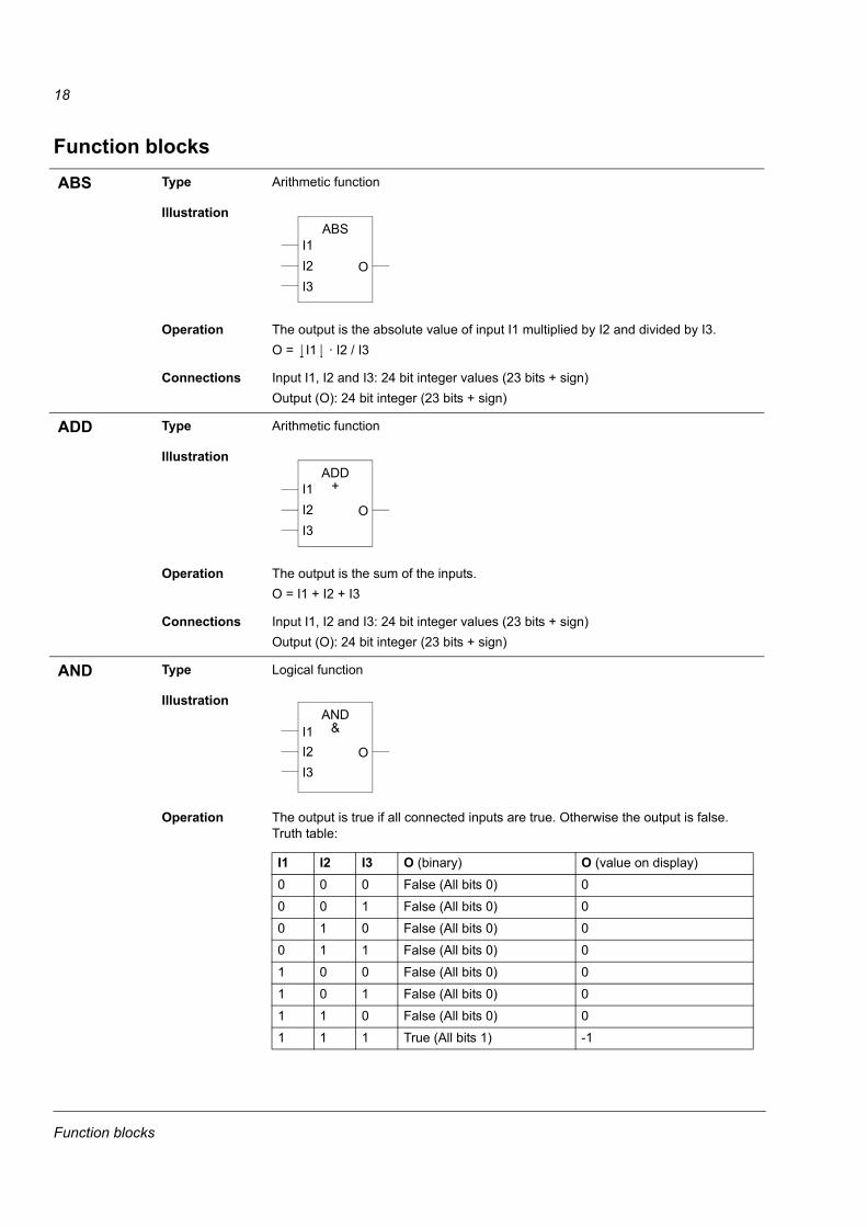
Function blocksABS Type Arithmetic function
Illustration
Operation The output is the absolute value of input I1 multiplied by I2 and divided by I3.O = I1 · I2 / I3
Connections Input I1, I2 and I3: 24 bit integer values (23 bits + sign)Output (O): 24 bit integer (23 bits + sign)
ADD Type Arithmetic function
Illustration
Operation The output is the sum of the inputs.O = I1 + I2 + I3
Connections Input I1, I2 and I3: 24 bit integer values (23 bits + sign)Output (O): 24 bit integer (23 bits + sign)
AND Type Logical function
Illustration
Operation The output is true if all connected inputs are true. Otherwise the output is false. Truth table:
I1I2I3
ABS
O
I1I2I3
ADD+
O
I1I2I3
AND&
O
I1 I2 I3 O (binary) O (value on display)0 0 0 False (All bits 0) 00 0 1 False (All bits 0) 00 1 0 False (All bits 0) 00 1 1 False (All bits 0) 01 0 0 False (All bits 0) 01 0 1 False (All bits 0) 01 1 0 False (All bits 0) 01 1 1 True (All bits 1) -1
Function blocks
19
Connections Input I1, I2 and I3: Boolean valuesOutput (O): 24 bit integer value (packed boolean)
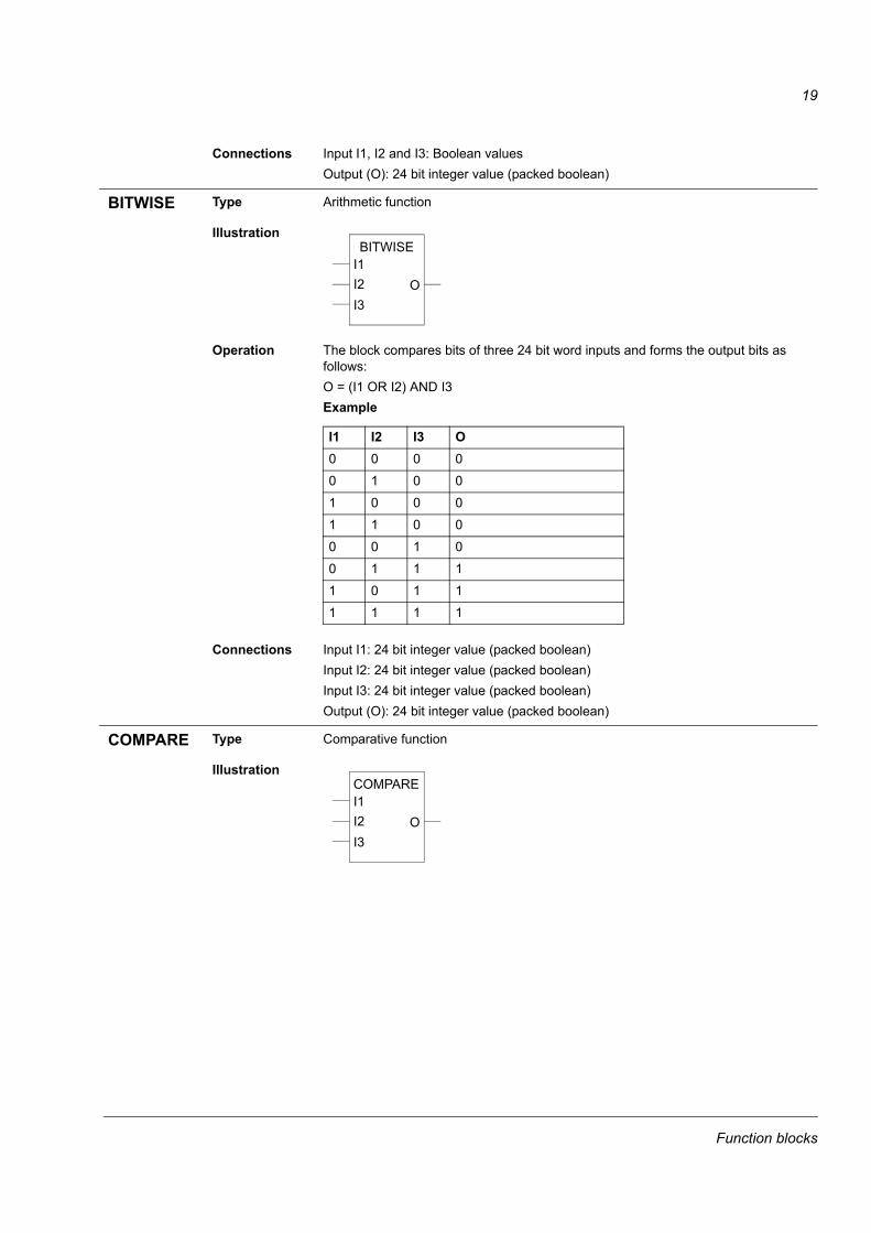
BITWISE Type Arithmetic function
Illustration
Operation The block compares bits of three 24 bit word inputs and forms the output bits as follows:O = (I1 OR I2) AND I3Example
Connections Input I1: 24 bit integer value (packed boolean)Input I2: 24 bit integer value (packed boolean)Input I3: 24 bit integer value (packed boolean)Output (O): 24 bit integer value (packed boolean)
COMPARE Type Comparative function
Illustration
I1I2I3
BITWISE
O
I1 I2 I3 O0 0 0 00 1 0 01 0 0 01 1 0 00 0 1 00 1 1 11 0 1 11 1 1 1
I1I2I3
COMPARE
O
Function blocks

20
Operation Output bits 0, 1 and 2:- If I1 > I2, O = � 001 (Output bit 0 is set.)- If I1 = I2, O = � 010 (Output bit 1 is set.)- If I1 < I2, O = � 100 (Output bit 2 is set.)Output bit 3:- If I1 > I2, O = � 1xxx (Output bit 3 is set and remains set until I1 < I2 - I3, after which bit 3 is reset.)Output value on display:
Connections Input I1, I2 and I3: 24 bit integer values (23 bits + sign)Output (O): 24 bit integer (packed boolean)
COUNT Type Counter function
Illustration
Operation The counter function counts rising edges of the input I1.The counter is reset by the rising edge of input I2 and limited to the value set with the input I3.I1: Trigger inputI2: ResetI3: Max limit for the counter (B0�B19 -> 0�1048575)O: Value of the counter (B0�B19 -> 0�1048575), and status of the counter (B20). B20 = 1: Counter is at max limit or input I3 is negative.
Connections Input I1 and I2: Boolean valuesInput I3: 24 bit integer value (20 bits used by the counter)Output (O): 24 bit integer value (20 bits for counter value and 4 indication bits)
bit 0 bit 1 bit 2 bit 3 O (value on display)0 0 0 0 01 0 0 0 10 1 0 0 20 0 1 0 40 0 0 1 81 0 0 1 90 1 0 1 100 0 1 1 12
I1I2I3
COUNT
O
Function blocks
21
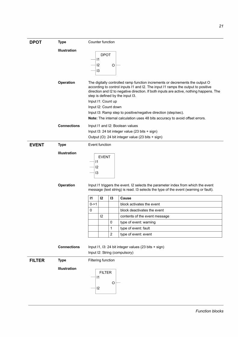
DPOT Type Counter function
Illustration
Operation The digitally controlled ramp function increments or decrements the output O according to control inputs I1 and I2. The input I1 ramps the output to positive direction and I2 to negative direction. If both inputs are active, nothing happens. The step is defined by the input I3.Input I1: Count upInput I2: Count downInput I3: Ramp step to positive/negative direction (step/sec).Note: The internal calculation uses 48 bits accuracy to avoid offset errors.
Connections Input I1 and I2: Boolean valuesInput I3: 24 bit integer value (23 bits + sign)Output (O): 24 bit integer value (23 bits + sign)
EVENT Type Event function
Illustration
Operation Input I1 triggers the event. I2 selects the parameter index from which the event message (text string) is read. I3 selects the type of the event (warning or fault).
Connections Input I1, I3: 24 bit integer values (23 bits + sign)Input I2: String (compulsory)
FILTER Type Filtering function
Illustration
I1I2I3
DPOT
O
I1I2I3
EVENT
I1 I2 I3 Cause0->1 block activates the event0 block deactivates the event
I2 contents of the event message0 type of event: warning1 type of event: fault2 type of event: event
I1
I2
FILTER
O
Function blocks
22
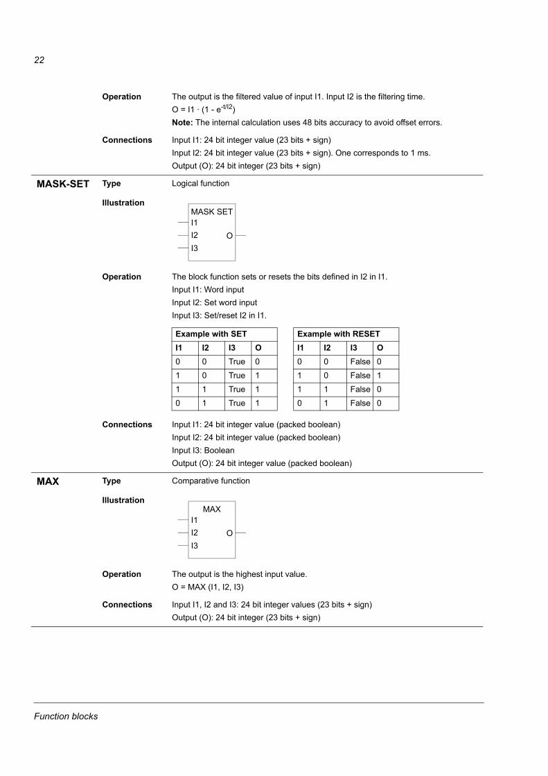
Operation The output is the filtered value of input I1. Input I2 is the filtering time.O = I1 · (1 - e-t/I2)Note: The internal calculation uses 48 bits accuracy to avoid offset errors.
Connections Input I1: 24 bit integer value (23 bits + sign)Input I2: 24 bit integer value (23 bits + sign). One corresponds to 1 ms.Output (O): 24 bit integer (23 bits + sign)
MASK-SET Type Logical function
Illustration
Operation The block function sets or resets the bits defined in I2 in I1.Input I1: Word inputInput I2: Set word inputInput I3: Set/reset I2 in I1.
Connections Input I1: 24 bit integer value (packed boolean)Input I2: 24 bit integer value (packed boolean)Input I3: BooleanOutput (O): 24 bit integer value (packed boolean)
MAX Type Comparative function
Illustration
Operation The output is the highest input value.O = MAX (I1, I2, I3)
Connections Input I1, I2 and I3: 24 bit integer values (23 bits + sign)Output (O): 24 bit integer (23 bits + sign)
I1I2I3
MASK SET
O
Example with SET Example with RESETI1 I2 I3 O I1 I2 I3 O0 0 True 0 0 0 False 01 0 True 1 1 0 False 11 1 True 1 1 1 False 00 1 True 1 0 1 False 0
I1I2I3
MAX
O
Function blocks
23
MIN Type Comparative function
Illustration
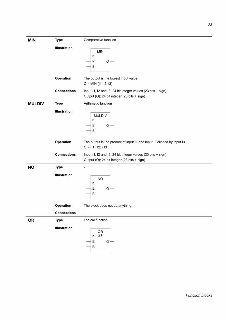
Operation The output is the lowest input value.O = MIN (I1, I2, I3)
Connections Input I1, I2 and I3: 24 bit integer values (23 bits + sign)Output (O): 24 bit integer (23 bits + sign)
MULDIV Type Arithmetic function
Illustration
Operation The output is the product of input I1 and input I2 divided by input I3.O = (I1 · I2) / I3
Connections Input I1, I2 and I3: 24 bit integer values (23 bits + sign)Output (O): 24 bit integer (23 bits + sign)
NO Type -
Illustration
Operation The block does not do anything.
Connections -
OR Type Logical function
Illustration
I1I2I3
MIN
O
I1I2I3
MULDIV
O
I1I2I3
NO
O
I1I2I3
OR>1
O
Function blocks
24
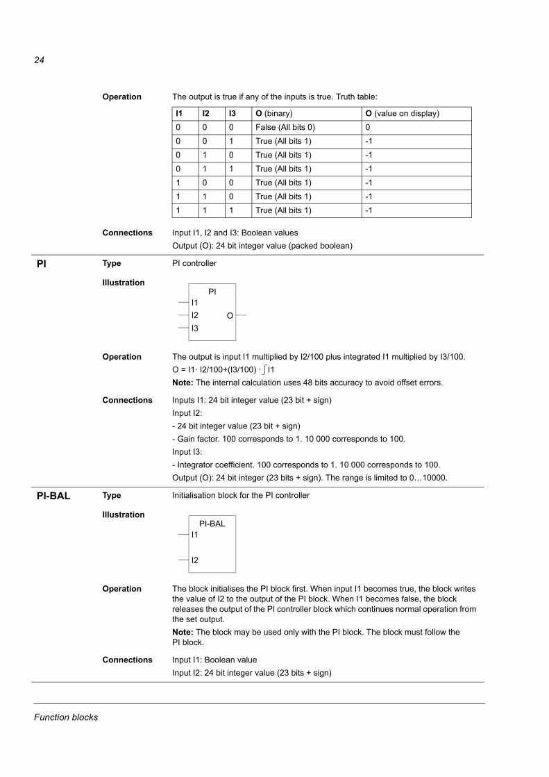
Operation The output is true if any of the inputs is true. Truth table:
Connections Input I1, I2 and I3: Boolean valuesOutput (O): 24 bit integer value (packed boolean)
PI Type PI controller
Illustration
Operation The output is input I1 multiplied by I2/100 plus integrated I1 multiplied by I3/100. O = I1· I2/100+(I3/100) · I1Note: The internal calculation uses 48 bits accuracy to avoid offset errors.
Connections Inputs I1: 24 bit integer value (23 bit + sign)Input I2:- 24 bit integer value (23 bit + sign) - Gain factor. 100 corresponds to 1. 10 000 corresponds to 100.Input I3:- Integrator coefficient. 100 corresponds to 1. 10 000 corresponds to 100.Output (O): 24 bit integer (23 bits + sign). The range is limited to 0�10000.
PI-BAL Type Initialisation block for the PI controller
Illustration
Operation The block initialises the PI block first. When input I1 becomes true, the block writes the value of I2 to the output of the PI block. When I1 becomes false, the block releases the output of the PI controller block which continues normal operation from the set output.Note: The block may be used only with the PI block. The block must follow the PI block.
Connections Input I1: Boolean valueInput I2: 24 bit integer value (23 bits + sign)
I1 I2 I3 O (binary) O (value on display)0 0 0 False (All bits 0) 00 0 1 True (All bits 1) -10 1 0 True (All bits 1) -10 1 1 True (All bits 1) -11 0 0 True (All bits 1) -11 1 0 True (All bits 1) -11 1 1 True (All bits 1) -1
I1I2I3
PI
O
I1
I2
PI-BAL
Function blocks
25
PI-BIPOLAR
Type PI controller
Illustration
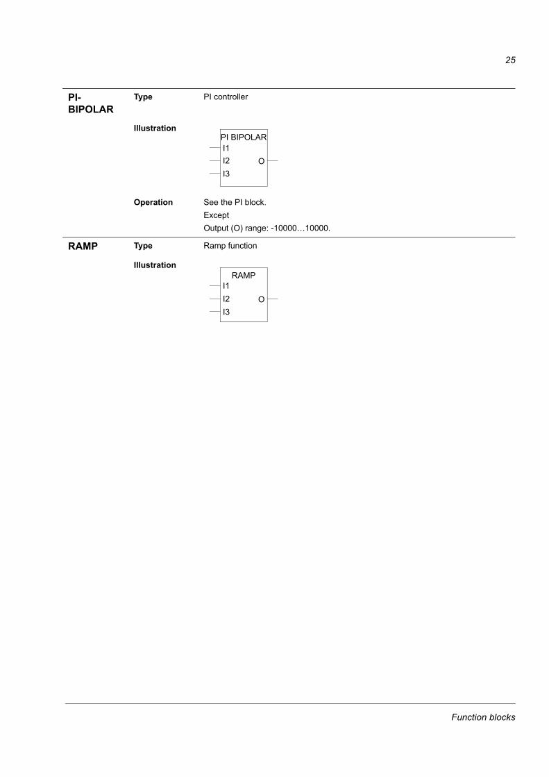
Operation See the PI block.Except Output (O) range: -10000�10000.
RAMP Type Ramp function
Illustration
I1I2I3
PI BIPOLAR
O
I1I2I3
RAMP
O
Function blocks
26
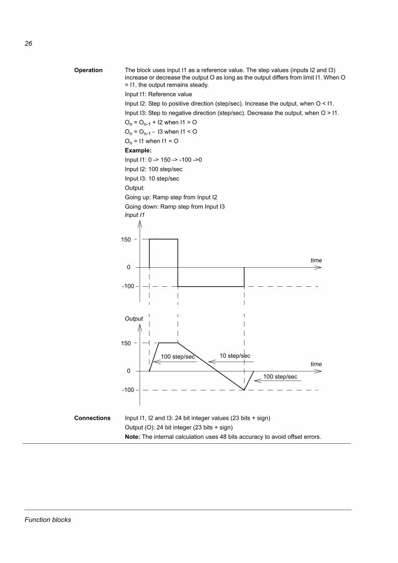
Operation The block uses input I1 as a reference value. The step values (inputs I2 and I3) increase or decrease the output O as long as the output differs from limit I1. When O = I1, the output remains steady.Input I1: Reference valueInput I2: Step to positive direction (step/sec). Increase the output, when O < I1.Input I3: Step to negative direction (step/sec). Decrease the output, when O > I1.On = On-1 + I2 when I1 > OOn = On-1 - I3 when I1 < OOn = I1 when I1 = OExample:Input I1: 0 -> 150 -> -100 ->0Input I2: 100 step/secInput I3: 10 step/secOutput: Going up: Ramp step from Input I2Going down: Ramp step from Input I3
Connections Input I1, I2 and I3: 24 bit integer values (23 bits + sign)Output (O): 24 bit integer (23 bits + sign)Note: The internal calculation uses 48 bits accuracy to avoid offset errors.
time
Input I1
0
150
-100
time
Output
0
150
-100
100 step/sec
100 step/sec
10 step/sec
Function blocks
27
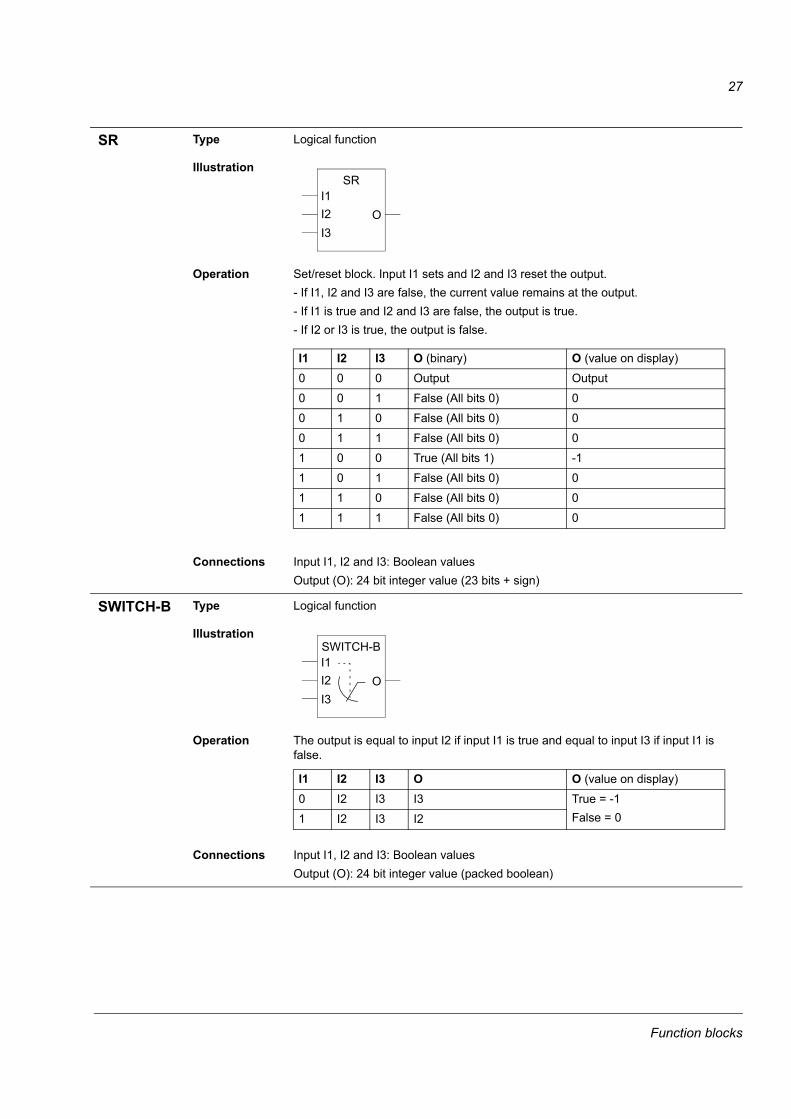
SR Type Logical function
Illustration
Operation Set/reset block. Input I1 sets and I2 and I3 reset the output.- If I1, I2 and I3 are false, the current value remains at the output.- If I1 is true and I2 and I3 are false, the output is true. - If I2 or I3 is true, the output is false.
Connections Input I1, I2 and I3: Boolean valuesOutput (O): 24 bit integer value (23 bits + sign)
SWITCH-B Type Logical function
Illustration
Operation The output is equal to input I2 if input I1 is true and equal to input I3 if input I1 is false.
Connections Input I1, I2 and I3: Boolean valuesOutput (O): 24 bit integer value (packed boolean)
I1I2I3
SR
O
I1 I2 I3 O (binary) O (value on display)0 0 0 Output Output0 0 1 False (All bits 0) 00 1 0 False (All bits 0) 00 1 1 False (All bits 0) 01 0 0 True (All bits 1) -11 0 1 False (All bits 0) 01 1 0 False (All bits 0) 01 1 1 False (All bits 0) 0
I1I2I3
SWITCH-B
O
I1 I2 I3 O O (value on display)0 I2 I3 I3 True = -1
False = 01 I2 I3 I2
Function blocks
28
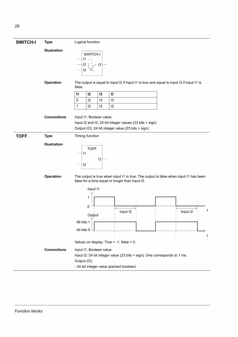
SWITCH-I Type Logical function
Illustration
Operation The output is equal to input I2 if input I1 is true and equal to input I3 if input I1 is false.
Connections Input I1: Boolean valueInput I2 and I3: 24 bit integer values (23 bits + sign)Output (O): 24 bit integer value (23 bits + sign)
TOFF Type Timing function
Illustration
Operation The output is true when input I1 is true. The output is false when input I1 has been false for a time equal or longer than input I2.
Values on display: True = -1, false = 0.
Connections Input I1: Boolean valueInput I2: 24 bit integer value (23 bits + sign). One corresponds to 1 ms.Output (O):- 24 bit integer value (packed boolean)
I1I2I3
SWITCH-I
O
I1 I2 I3 O0 I2 I3 I31 I2 I3 I2
I1
I2
TOFF
O
Input I1
t
1
0Input I2
Output
t
All bits 1
All bits 0
Input I2
Function blocks
29
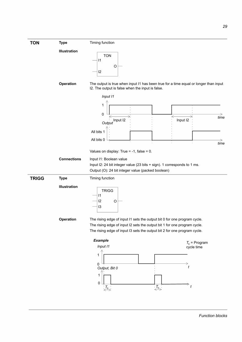
TON Type Timing function
Illustration
Operation The output is true when input I1 has been true for a time equal or longer than input I2. The output is false when the input is false.
Values on display: True = -1, false = 0.
Connections Input I1: Boolean valueInput I2: 24 bit integer value (23 bits + sign). 1 corresponds to 1 ms.Output (O): 24 bit integer value (packed boolean)
TRIGG Type Timing function
Illustration
Operation The rising edge of input I1 sets the output bit 0 for one program cycle.The rising edge of input I2 sets the output bit 1 for one program cycle.The rising edge of input I3 sets the output bit 2 for one program cycle.
I1
I2
TON
O
Input I1
time
1
0Input I2 Input I2
Output
time
All bits 1
All bits 0
I1I2I3
TRIGG
O
Input I1
t
1
0Output, Bit 0
t
1
0Tc
Example
Tc
Tc = Program cycle time
Function blocks
30
Connections Input I1, I2 and I3: Boolean valuesOutput (O):- 24 bit integer value (23 bits + sign)
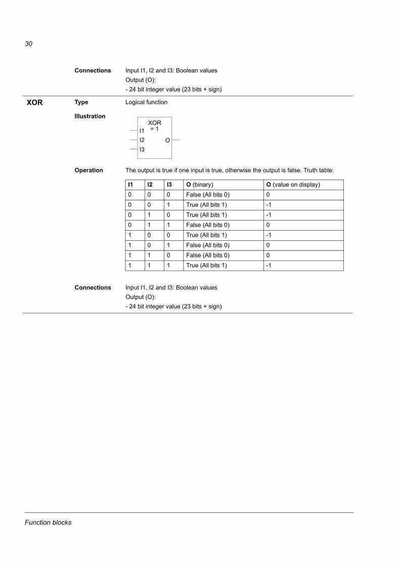
XOR Type Logical function
Illustration
Operation The output is true if one input is true, otherwise the output is false. Truth table:
Connections Input I1, I2 and I3: Boolean valuesOutput (O):- 24 bit integer value (23 bits + sign)
I1I2I3
XOR= 1
O
I1 I2 I3 O (binary) O (value on display)0 0 0 False (All bits 0) 00 0 1 True (All bits 1) -10 1 0 True (All bits 1) -10 1 1 False (All bits 0) 01 0 0 True (All bits 1) -11 0 1 False (All bits 0) 01 1 0 False (All bits 0) 01 1 1 True (All bits 1) -1
Function blocks
31
Actual signals and parameters in ACS800 Standard Application Program
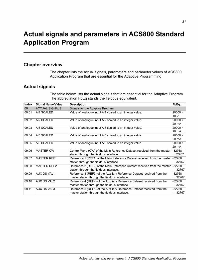
Chapter overviewThe chapter lists the actual signals, parameters and parameter values of ACS800 Application Program that are essential for the Adaptive Programming.
Actual signalsThe table below lists the actual signals that are essential for the Adaptive Program. The abbreviation FbEq stands the fieldbus equivalent.
Index Signal Name/Value Description FbEq.09 ACTUAL SIGNALS Signals for the Adaptive Program09.01 AI1 SCALED Value of analogue input AI1 scaled to an integer value. 20000 =
10 V09.02 AI2 SCALED Value of analogue input AI2 scaled to an integer value. 20000 =
20 mA09.03 AI3 SCALED Value of analogue input AI3 scaled to an integer value. 20000 =
20 mA09.04 AI5 SCALED Value of analogue input AI5 scaled to an integer value. 20000 =
20 mA09.05 AI6 SCALED Value of analogue input AI6 scaled to an integer value. 20000 =
20 mA09.06 MASTER CW Control Word (CW) of the Main Reference Dataset received from the master
station through the fieldbus interface.-32768 �32767
09.07 MASTER REF1 Reference 1 (REF1) of the Main Reference Dataset received from the master station through the fieldbus interface
-32768 � 32767
09.08 MASTER REF2 Reference 2 (REF2) of the Main Reference Dataset received from the master station through the fieldbus interface.
-32768 � 32767
09.09 AUX DS VAL1 Reference 3 (REF3) of the Auxiliary Reference Dataset received from the master station through the fieldbus interface.
-32768 � 32767
09.10 AUX DS VAL2 Reference 4 (REF4) of the Auxiliary Reference Dataset received from the master station through the fieldbus interface.
-32768 � 32767
09.11 AUX DS VAL3 Reference 5 (REF5) of the Auxiliary Reference Dataset received from the master station through the fieldbus interface.
-32768 � 32767
Actual signals and parameters in ACS800 Standard Application Program
32
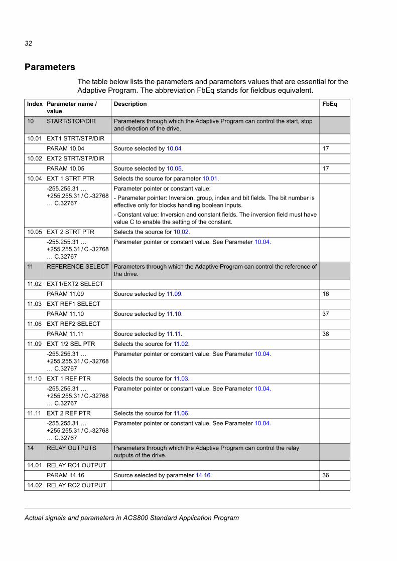
ParametersThe table below lists the parameters and parameters values that are essential for the Adaptive Program. The abbreviation FbEq stands for fieldbus equivalent.
Index Parameter name / value
Description FbEq
10 START/STOP/DIR Parameters through which the Adaptive Program can control the start, stop and direction of the drive.
10.01 EXT1 STRT/STP/DIRPARAM 10.04 Source selected by 10.04 17
10.02 EXT2 STRT/STP/DIRPARAM 10.05 Source selected by 10.05. 17
10.04 EXT 1 STRT PTR Selects the source for parameter 10.01.-255.255.31 � +255.255.31 / C.-32768 � C.32767
Parameter pointer or constant value:- Parameter pointer: Inversion, group, index and bit fields. The bit number is effective only for blocks handling boolean inputs.- Constant value: Inversion and constant fields. The inversion field must have value C to enable the setting of the constant.
10.05 EXT 2 STRT PTR Selects the source for 10.02.-255.255.31 � +255.255.31 / C.-32768 � C.32767
Parameter pointer or constant value. See Parameter 10.04.
11 REFERENCE SELECT Parameters through which the Adaptive Program can control the reference of the drive.
11.02 EXT1/EXT2 SELECTPARAM 11.09 Source selected by 11.09. 16
11.03 EXT REF1 SELECTPARAM 11.10 Source selected by 11.10. 37
11.06 EXT REF2 SELECTPARAM 11.11 Source selected by 11.11. 38
11.09 EXT 1/2 SEL PTR Selects the source for 11.02.-255.255.31 � +255.255.31 / C.-32768 � C.32767
Parameter pointer or constant value. See Parameter 10.04.
11.10 EXT 1 REF PTR Selects the source for 11.03.-255.255.31 � +255.255.31 / C.-32768 � C.32767
Parameter pointer or constant value. See Parameter 10.04.
11.11 EXT 2 REF PTR Selects the source for 11.06.-255.255.31 � +255.255.31 / C.-32768 � C.32767
Parameter pointer or constant value. See Parameter 10.04.
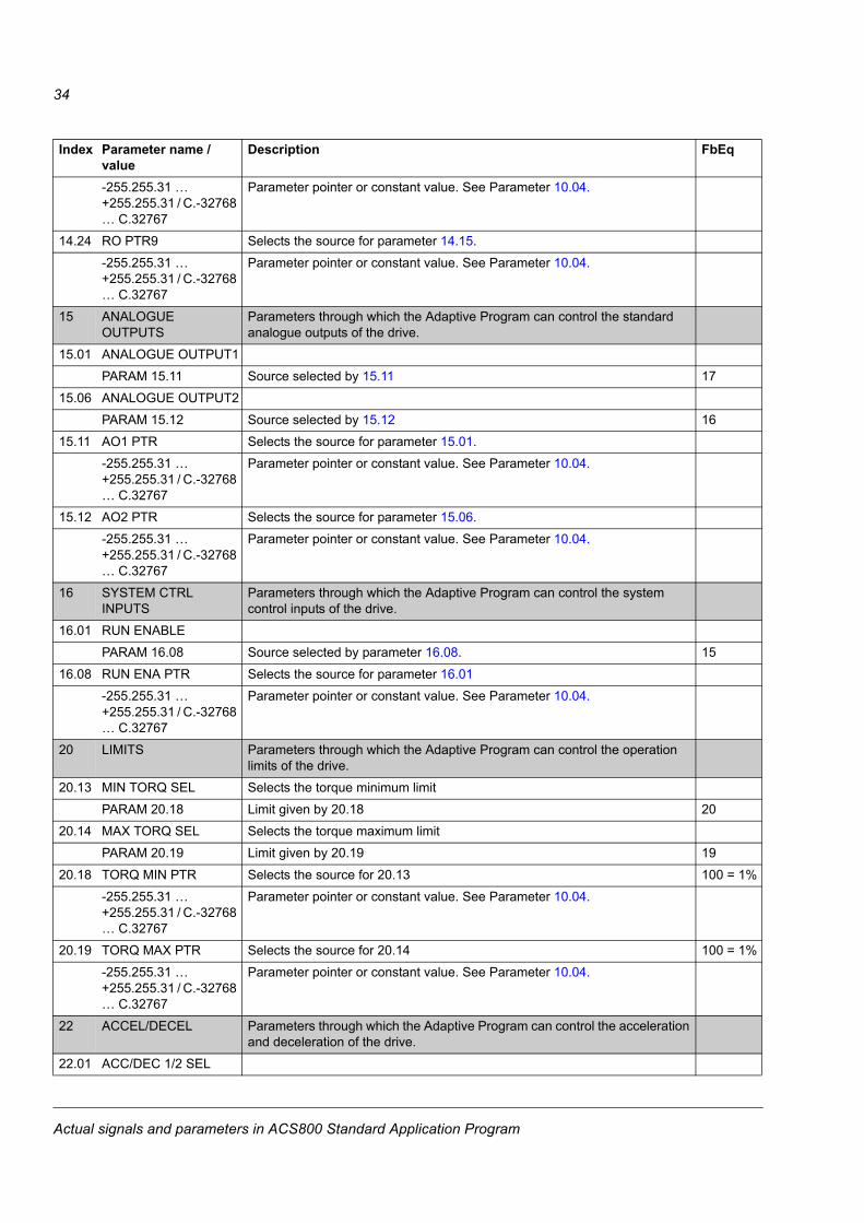
14 RELAY OUTPUTS Parameters through which the Adaptive Program can control the relay outputs of the drive.
14.01 RELAY RO1 OUTPUTPARAM 14.16 Source selected by parameter 14.16. 36
14.02 RELAY RO2 OUTPUT
Actual signals and parameters in ACS800 Standard Application Program
33
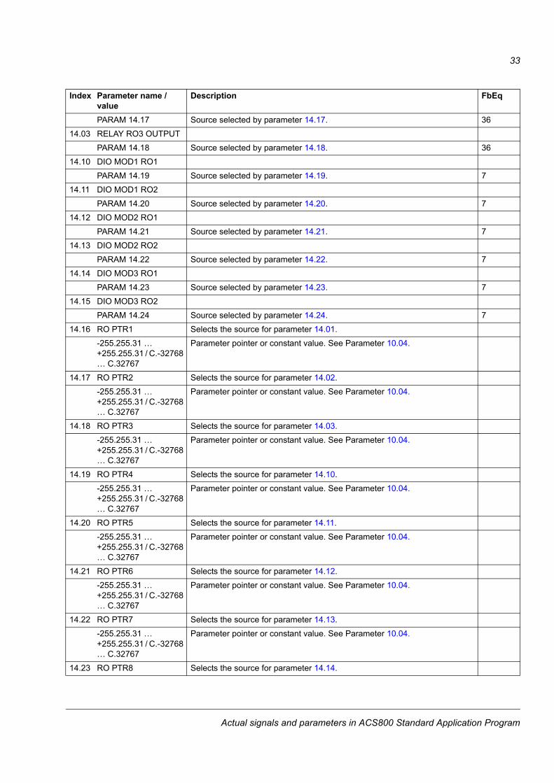
PARAM 14.17 Source selected by parameter 14.17. 3614.03 RELAY RO3 OUTPUT
PARAM 14.18 Source selected by parameter 14.18. 3614.10 DIO MOD1 RO1
PARAM 14.19 Source selected by parameter 14.19. 714.11 DIO MOD1 RO2
PARAM 14.20 Source selected by parameter 14.20. 714.12 DIO MOD2 RO1
PARAM 14.21 Source selected by parameter 14.21. 714.13 DIO MOD2 RO2
PARAM 14.22 Source selected by parameter 14.22. 714.14 DIO MOD3 RO1
PARAM 14.23 Source selected by parameter 14.23. 714.15 DIO MOD3 RO2
PARAM 14.24 Source selected by parameter 14.24. 714.16 RO PTR1 Selects the source for parameter 14.01.
-255.255.31 � +255.255.31 / C.-32768 � C.32767
Parameter pointer or constant value. See Parameter 10.04.
14.17 RO PTR2 Selects the source for parameter 14.02.-255.255.31 � +255.255.31 / C.-32768 � C.32767
Parameter pointer or constant value. See Parameter 10.04.
14.18 RO PTR3 Selects the source for parameter 14.03.-255.255.31 � +255.255.31 / C.-32768 � C.32767
Parameter pointer or constant value. See Parameter 10.04.
14.19 RO PTR4 Selects the source for parameter 14.10.-255.255.31 � +255.255.31 / C.-32768 � C.32767
Parameter pointer or constant value. See Parameter 10.04.
14.20 RO PTR5 Selects the source for parameter 14.11.-255.255.31 � +255.255.31 / C.-32768 � C.32767
Parameter pointer or constant value. See Parameter 10.04.
14.21 RO PTR6 Selects the source for parameter 14.12.-255.255.31 � +255.255.31 / C.-32768 � C.32767
Parameter pointer or constant value. See Parameter 10.04.
14.22 RO PTR7 Selects the source for parameter 14.13.-255.255.31 � +255.255.31 / C.-32768 � C.32767
Parameter pointer or constant value. See Parameter 10.04.
14.23 RO PTR8 Selects the source for parameter 14.14.
Index Parameter name / value
Description FbEq
Actual signals and parameters in ACS800 Standard Application Program
34
-255.255.31 � +255.255.31 / C.-32768 � C.32767
Parameter pointer or constant value. See Parameter 10.04.
14.24 RO PTR9 Selects the source for parameter 14.15.-255.255.31 � +255.255.31 / C.-32768 � C.32767
Parameter pointer or constant value. See Parameter 10.04.
15 ANALOGUE OUTPUTS
Parameters through which the Adaptive Program can control the standard analogue outputs of the drive.
15.01 ANALOGUE OUTPUT1PARAM 15.11 Source selected by 15.11 17
15.06 ANALOGUE OUTPUT2PARAM 15.12 Source selected by 15.12 16
15.11 AO1 PTR Selects the source for parameter 15.01.-255.255.31 � +255.255.31 / C.-32768 � C.32767
Parameter pointer or constant value. See Parameter 10.04.
15.12 AO2 PTR Selects the source for parameter 15.06.-255.255.31 � +255.255.31 / C.-32768 � C.32767
Parameter pointer or constant value. See Parameter 10.04.
16 SYSTEM CTRL INPUTS
Parameters through which the Adaptive Program can control the system control inputs of the drive.
16.01 RUN ENABLEPARAM 16.08 Source selected by parameter 16.08. 15
16.08 RUN ENA PTR Selects the source for parameter 16.01-255.255.31 � +255.255.31 / C.-32768 � C.32767
Parameter pointer or constant value. See Parameter 10.04.
20 LIMITS Parameters through which the Adaptive Program can control the operation limits of the drive.
20.13 MIN TORQ SEL Selects the torque minimum limitPARAM 20.18 Limit given by 20.18 20
20.14 MAX TORQ SEL Selects the torque maximum limitPARAM 20.19 Limit given by 20.19 19
20.18 TORQ MIN PTR Selects the source for 20.13 100 = 1%-255.255.31 � +255.255.31 / C.-32768 � C.32767
Parameter pointer or constant value. See Parameter 10.04.
20.19 TORQ MAX PTR Selects the source for 20.14 100 = 1%-255.255.31 � +255.255.31 / C.-32768 � C.32767
Parameter pointer or constant value. See Parameter 10.04.
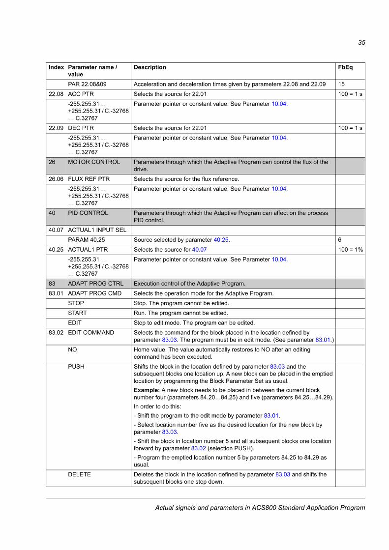
22 ACCEL/DECEL Parameters through which the Adaptive Program can control the acceleration and deceleration of the drive.
22.01 ACC/DEC 1/2 SEL
Index Parameter name / value
Description FbEq
Actual signals and parameters in ACS800 Standard Application Program
35
PAR 22.08&09 Acceleration and deceleration times given by parameters 22.08 and 22.09 1522.08 ACC PTR Selects the source for 22.01 100 = 1 s
-255.255.31 � +255.255.31 / C.-32768 � C.32767
Parameter pointer or constant value. See Parameter 10.04.
22.09 DEC PTR Selects the source for 22.01 100 = 1 s-255.255.31 � +255.255.31 / C.-32768 � C.32767
Parameter pointer or constant value. See Parameter 10.04.
26 MOTOR CONTROL Parameters through which the Adaptive Program can control the flux of the drive.
26.06 FLUX REF PTR Selects the source for the flux reference.-255.255.31 � +255.255.31 / C.-32768 � C.32767
Parameter pointer or constant value. See Parameter 10.04.
40 PID CONTROL Parameters through which the Adaptive Program can affect on the process PID control.
40.07 ACTUAL1 INPUT SELPARAM 40.25 Source selected by parameter 40.25. 6
40.25 ACTUAL1 PTR Selects the source for 40.07 100 = 1%-255.255.31 � +255.255.31 / C.-32768 � C.32767
Parameter pointer or constant value. See Parameter 10.04.
83 ADAPT PROG CTRL Execution control of the Adaptive Program.83.01 ADAPT PROG CMD Selects the operation mode for the Adaptive Program.
STOP Stop. The program cannot be edited.START Run. The program cannot be edited.EDIT Stop to edit mode. The program can be edited.
83.02 EDIT COMMAND Selects the command for the block placed in the location defined by parameter 83.03. The program must be in edit mode. (See parameter 83.01.)
NO Home value. The value automatically restores to NO after an editing command has been executed.
PUSH Shifts the block in the location defined by parameter 83.03 and the subsequent blocks one location up. A new block can be placed in the emptied location by programming the Block Parameter Set as usual.Example: A new block needs to be placed in between the current block number four (parameters 84.20�84.25) and five (parameters 84.25�84.29).In order to do this:- Shift the program to the edit mode by parameter 83.01.- Select location number five as the desired location for the new block by parameter 83.03.- Shift the block in location number 5 and all subsequent blocks one location forward by parameter 83.02 (selection PUSH).- Program the emptied location number 5 by parameters 84.25 to 84.29 as usual.
DELETE Deletes the block in the location defined by parameter 83.03 and shifts the subsequent blocks one step down.
Index Parameter name / value
Description FbEq
Actual signals and parameters in ACS800 Standard Application Program
36
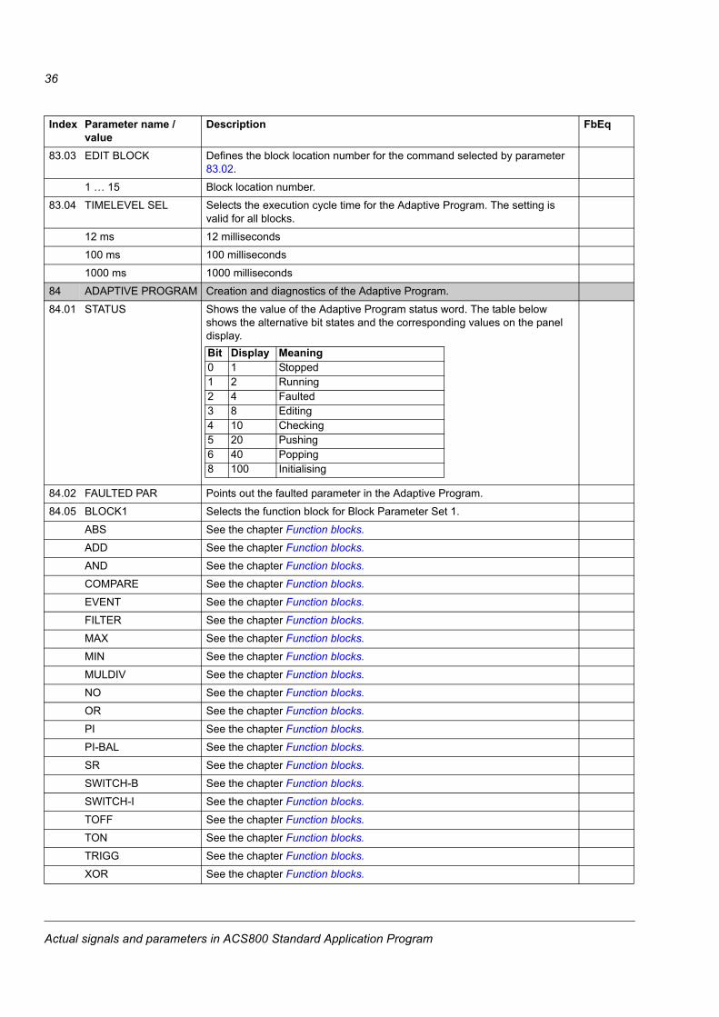
83.03 EDIT BLOCK Defines the block location number for the command selected by parameter 83.02.
1 � 15 Block location number.83.04 TIMELEVEL SEL Selects the execution cycle time for the Adaptive Program. The setting is
valid for all blocks.12 ms 12 milliseconds100 ms 100 milliseconds1000 ms 1000 milliseconds
84 ADAPTIVE PROGRAM Creation and diagnostics of the Adaptive Program.84.01 STATUS Shows the value of the Adaptive Program status word. The table below
shows the alternative bit states and the corresponding values on the panel display.
84.02 FAULTED PAR Points out the faulted parameter in the Adaptive Program.84.05 BLOCK1 Selects the function block for Block Parameter Set 1.
ABS See the chapter Function blocks.ADD See the chapter Function blocks.AND See the chapter Function blocks.COMPARE See the chapter Function blocks.EVENT See the chapter Function blocks.FILTER See the chapter Function blocks.MAX See the chapter Function blocks.MIN See the chapter Function blocks.MULDIV See the chapter Function blocks.NO See the chapter Function blocks.OR See the chapter Function blocks.PI See the chapter Function blocks.PI-BAL See the chapter Function blocks.SR See the chapter Function blocks.SWITCH-B See the chapter Function blocks.SWITCH-I See the chapter Function blocks.TOFF See the chapter Function blocks.TON See the chapter Function blocks.TRIGG See the chapter Function blocks.XOR See the chapter Function blocks.
Index Parameter name / value
Description FbEq
Bit Display Meaning0 1 Stopped1 2 Running2 4 Faulted3 8 Editing4 10 Checking5 20 Pushing6 40 Popping8 100 Initialising
Actual signals and parameters in ACS800 Standard Application Program
37
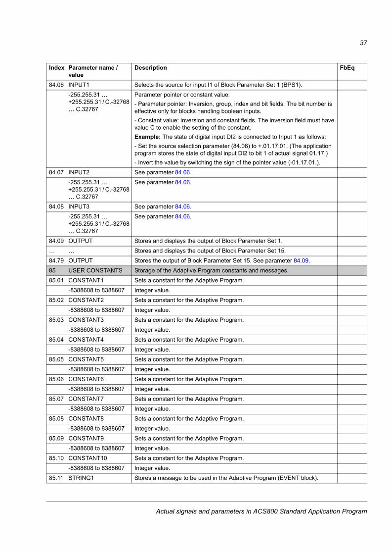
84.06 INPUT1 Selects the source for input I1 of Block Parameter Set 1 (BPS1). -255.255.31 � +255.255.31 / C.-32768 � C.32767
Parameter pointer or constant value:- Parameter pointer: Inversion, group, index and bit fields. The bit number is effective only for blocks handling boolean inputs.- Constant value: Inversion and constant fields. The inversion field must have value C to enable the setting of the constant.Example: The state of digital input DI2 is connected to Input 1 as follows:- Set the source selection parameter (84.06) to +.01.17.01. (The application program stores the state of digital input DI2 to bit 1 of actual signal 01.17.)- Invert the value by switching the sign of the pointer value (-01.17.01.).
84.07 INPUT2 See parameter 84.06.-255.255.31 � +255.255.31 / C.-32768 � C.32767
See parameter 84.06.
84.08 INPUT3 See parameter 84.06.-255.255.31 � +255.255.31 / C.-32768 � C.32767
See parameter 84.06.
84.09 OUTPUT Stores and displays the output of Block Parameter Set 1.� � Stores and displays the output of Block Parameter Set 15.84.79 OUTPUT Stores the output of Block Parameter Set 15. See parameter 84.09.85 USER CONSTANTS Storage of the Adaptive Program constants and messages.85.01 CONSTANT1 Sets a constant for the Adaptive Program.
-8388608 to 8388607 Integer value.85.02 CONSTANT2 Sets a constant for the Adaptive Program.
-8388608 to 8388607 Integer value.85.03 CONSTANT3 Sets a constant for the Adaptive Program.
-8388608 to 8388607 Integer value.85.04 CONSTANT4 Sets a constant for the Adaptive Program.
-8388608 to 8388607 Integer value.85.05 CONSTANT5 Sets a constant for the Adaptive Program.
-8388608 to 8388607 Integer value.85.06 CONSTANT6 Sets a constant for the Adaptive Program.
-8388608 to 8388607 Integer value.85.07 CONSTANT7 Sets a constant for the Adaptive Program.
-8388608 to 8388607 Integer value.85.08 CONSTANT8 Sets a constant for the Adaptive Program.
-8388608 to 8388607 Integer value.85.09 CONSTANT9 Sets a constant for the Adaptive Program.
-8388608 to 8388607 Integer value.85.10 CONSTANT10 Sets a constant for the Adaptive Program.
-8388608 to 8388607 Integer value.85.11 STRING1 Stores a message to be used in the Adaptive Program (EVENT block).
Index Parameter name / value
Description FbEq
Actual signals and parameters in ACS800 Standard Application Program
38
MESSAGE1 Message85.12 STRING2 Stores a message to be used in the Adaptive Program (EVENT block).
MESSAGE2 Message85.13 STRING3 Stores a message to be used in the Adaptive Program (EVENT block).
MESSAGE3 Message85.14 STRING4 Stores a message to be used in the Adaptive Program (EVENT block).
MESSAGE4 Message85.15 STRING5 Stores a message to be used in the Adaptive Program (EVENT block).
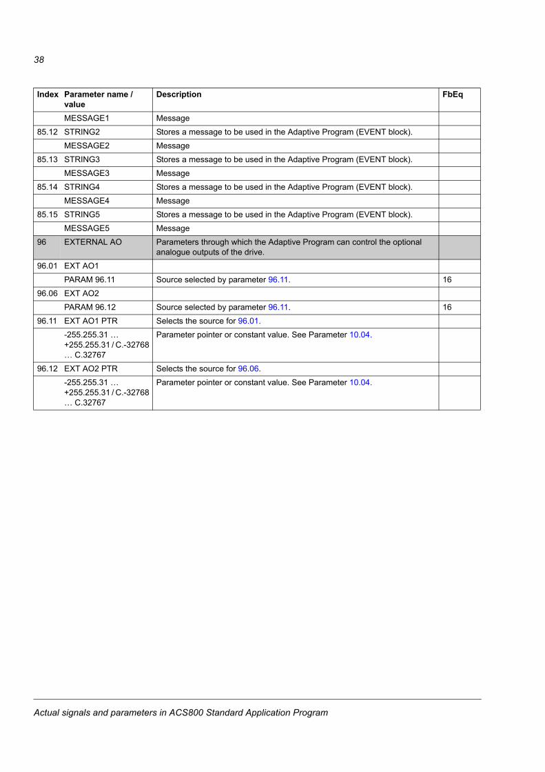
MESSAGE5 Message96 EXTERNAL AO Parameters through which the Adaptive Program can control the optional
analogue outputs of the drive.96.01 EXT AO1
PARAM 96.11 Source selected by parameter 96.11. 1696.06 EXT AO2
PARAM 96.12 Source selected by parameter 96.11. 1696.11 EXT AO1 PTR Selects the source for 96.01.
-255.255.31 � +255.255.31 / C.-32768 � C.32767
Parameter pointer or constant value. See Parameter 10.04.
96.12 EXT AO2 PTR Selects the source for 96.06.-255.255.31 � +255.255.31 / C.-32768 � C.32767
Parameter pointer or constant value. See Parameter 10.04.
Index Parameter name / value
Description FbEq
Actual signals and parameters in ACS800 Standard Application Program

39
Customer diagrams
Chapter overviewThis chapter includes three blank block diagram sheets on which the Adaptive Program can be documented.
Customer diagrams


ABB Oy AC Drives P.O.Box 184 FI-00381 Helsinki FINLAND Telephone: +358 10 22 11 Fax: +358 10 22 22681 Internet: http://www.abb.com
3AFE
645
2727
4 R
ev C
/ EN
EF
FEC
TIVE
: 08.
04.2
005
ABB Inc. Automation Technologies Drives & Motors 16250 West Glendale Drive New Berlin, WI 53151 USA Telephone: 262 785-8378
800-HELP-365 Fax: 262 780-5135