EN 206 Prof. Doolla EN 206 - Power Electronics and...
19
EN 206 1/19 Prof. Doolla Introduction Phasor Diagram Eql Ckt OC & SC Test EN 206 - Power Electronics and Machines Transformers Suryanarayana Doolla Department of Energy Science and Engineering Indian Institute of Technology, Bombay [email protected]
Transcript of EN 206 Prof. Doolla EN 206 - Power Electronics and...

EN 2061/19
Prof. Doolla
Introduction
PhasorDiagram
Eql Ckt
OC & SC Test
EN 206 - Power Electronics and MachinesTransformers
Suryanarayana DoollaDepartment of Energy Science and Engineering
Indian Institute of Technology, [email protected]

EN 2062/19
Prof. Doolla
Introduction
PhasorDiagram
Eql Ckt
OC & SC Test
Lecture Organization - Modules
Introduction and Power Semiconductor Switches
Module 1: Transformers
Module 2: AC/DC converter / Rectifier
Module 3: DC machines and Drives
Module 4: DC/DC converter
Module 5: Induction Machine
Module 6: DC/AC converter / Inverter
Module 7: AC/AC converter / Cyclo converter
Module 8: Synchronous Machine
Module 9: Special Topics: Machines, HVDC, APF

EN 2063/19
Prof. Doolla
Introduction
PhasorDiagram
Eql Ckt
OC & SC Test
Review of Last Class
Transformers
Types, applications, constructionPrinciple of operation, emf equationPhasor diagram for ideal transformer and no loadcondition, impedance transformation

EN 2064/19
Prof. Doolla
Introduction
PhasorDiagram
Eql Ckt
OC & SC Test
Phasor Diagram - No Load
α: Hysteresis angle, Ie : excitingcurrent, Iφ : Magnetizingcurrent, Ic : Core loss component
r1: primary resistance
x1: fictituous quantityintroduced to represent theleakage flux in primary
Primary leakage impedance dropis about 2 to 5% even at fullload.
The magnetizing current istypically 1% of full load currentand hence is neglected.

EN 2065/19
Prof. Doolla
Introduction
PhasorDiagram
Eql Ckt
OC & SC Test
Phasor Diagram - Lagging Load
θ1 and θ2 is the power factor ofthe load and source respectively.
r1: primary resistance
x1: fictituous quantityintroduced to represent theleakage flux in primary
Primary leakage impedance dropis about 2 to 5% even at fullload.
Phasor diagram is helpful only:
When a transformer is to bestudied aloneWhen the internal behaviour ofthe transformer is to beunderstood

EN 2066/19
Prof. Doolla
Introduction
PhasorDiagram
Eql Ckt
OC & SC Test
Equivalent Circuit
With Exciting current neglected:
Exact equivalent circuit:

EN 2067/19
Prof. Doolla
Introduction
PhasorDiagram
Eql Ckt
OC & SC Test
Equivalent Circuit
Equivalent circuit referred to primary:

EN 2068/19
Prof. Doolla
Introduction
PhasorDiagram
Eql Ckt
OC & SC Test
Problem-1
A 33 kVA, 2200/220V, single phase transformer has resistancesand leakage reactances as follows:
r1 = 2.4Ω, r2 = 6.0Ω, x1 = 0.03Ω, x2 = 0.07ΩSubscripts 1 and 2 denote high voltage and low voltagewindings respectively.(a) Determine the total ohmic losses at full load.(b) Calculate the voltage to be applied to the HV side in orderto obtain a short circuit current of 160A in the LV side. Alsofind the input power for this condition.
EN 2069/19
Prof. Doolla
Introduction
PhasorDiagram
Eql Ckt
OC & SC Test
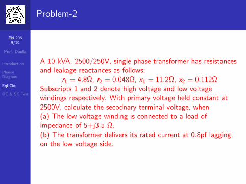
Problem-2
A 10 kVA, 2500/250V, single phase transformer has resistancesand leakage reactances as follows:
r1 = 4.8Ω, r2 = 0.048Ω, x1 = 11.2Ω, x2 = 0.112ΩSubscripts 1 and 2 denote high voltage and low voltagewindings respectively. With primary voltage held constant at2500V, calculate the secodnary terminal voltage, when(a) The low voltage winding is connected to a load ofimpedance of 5+j3.5 Ω.(b) The transformer delivers its rated current at 0.8pf laggingon the low voltage side.

EN 20610/19
Prof. Doolla
Introduction
PhasorDiagram
Eql Ckt
OC & SC Test
Open Circuit (OC) and Short Circuit (SC) Test
OC and SC test on a transformer are performed to find out:
The parameters of equivalent circuit
Voltage regulation
Efficiency
All these tests are performed without loading the transformer.

EN 20611/19
Prof. Doolla
Introduction
PhasorDiagram
Eql Ckt
OC & SC Test
Open Circuit Test
Circuit diagram for OC Test:
1 The meters are connected on low voltage side of thetransformer
2 The high voltage side is kept open, and rated frequencyvoltage is applied to the primary using variac
3 At this condition, the rated flux flows into the core of thetransformer.

EN 20612/19
Prof. Doolla
Introduction
PhasorDiagram
Eql Ckt
OC & SC Test
Open Circuit Test
What do the meter(s) reading indicate?
The ammeter indicate the excitation current of thetransformer (no load current)
As the value of Ie is small, the voltage drop across theleakage impedance can be negleced.
The applied voltage can be assumed to be equal to emfinduced (for all practical purpose)
The reading of wattmeter gives core losses in the machine(neglecting copper losses).

EN 20613/19
Prof. Doolla
Introduction
PhasorDiagram
Eql Ckt
OC & SC Test
OC Test - Analysis
Let V1 be the voltage applied across the primary (LV) side ofthe transformer, Ie is the exciting current, Pc is core loss, then:
Pc = V1Ie cos θ, ∴ no load power factor is given by:cosθo = Pc
V1IeFrom the phasor diagram, we can obtain that:
Ic = Iecosθo and Iφ = sinθo
∴ Rc = V1Iecosθo
, Xφ = V1Iesinθo

EN 20614/19
Prof. Doolla
Introduction
PhasorDiagram
Eql Ckt
OC & SC Test
OC Test - Summary
OC test on a transformer gives the following information
Core losses at rated voltage and frequency
The shunt branch parameters of the equivalent circuit (Rc
and Xφ)
Turns ratio of the transformer
Note: The values of Rc and Xφ determined are to be referredto the side in which instruments are placed.

EN 20615/19
Prof. Doolla
Introduction
PhasorDiagram
Eql Ckt
OC & SC Test
Short Circuit Test
Circuit diagram for SC Test:
1 The low voltage side terminals are short circuted.2 The meters are connected on high voltage side of the
transformer.3 Voltage is applied to the primary using variac ( 2 to 12%
of Vrated).4 At this condition, full load current will flow in both the
windings.5 Core flux is 1 to 6% of its rated value.

EN 20616/19
Prof. Doolla
Introduction
PhasorDiagram
Eql Ckt
OC & SC Test
Short Circuit Test
What do the meter(s) reading indicate?
The ammeter indicate full load current of HV side
The reading of wattmeter gives copper losses in themachine at full load (neglecting core losses).
The exciting current may be neglected to obtain asimplified equivalent circuit.

EN 20617/19
Prof. Doolla
Introduction
PhasorDiagram
Eql Ckt
OC & SC Test
Short Circuit Test - Analysis
If re,hv , xe,hv and ze,hv represent equivalent resistance, leakagereactance and impedance referred to hv side:
ze,hv = VscIsc
re,hv = PscI 2sc
xe,hv =√
z2e,hv − r2e,hv

EN 20618/19
Prof. Doolla
Introduction
PhasorDiagram
Eql Ckt
OC & SC Test
Short Circuit Test - Summary
SC test is generally performed on high voltage side
The readings of SC test help in determining the resistanceand leakage reactance of the windings.
It is possible to determine the efficieny of the transformerusing SC test data and core losses.

EN 20619/19
Prof. Doolla
Introduction
PhasorDiagram
Eql Ckt
OC & SC Test
Summary
Transformers
Phasor diagram of transformer (loaded)Equivalent CircuitOpen Circuit and Short Circuit Test
Next ClassAuto Transformer and Three phase Transformers
Thank you!!
For Further Reading:
Transformer Engineering: Design and Practice Authors:S.V. Kulkarni and S.A. Khaparde Publisher: MarcelDekker (Taylor & Francis Group), New York, May 2004ISBN: 0-8247-5653-3
Electric Machinery: A. E. Fitzgerald, C. Kingsley, S. D.Umans. Publisher: TMH, New Delhi, India, 2009