Eurocode 1 actions sur les structures partie 1-4 actions générales actions du vent

The European Union
In order to promote public education and public safety, equal justice for all, a better informed citizenry, the rule of law, world trade and world peace, this legal document is hereby made available on a noncommercial basis, as it is the right of all humans to know and speak the laws that govern them.
≠ EDICT OF GOVERNMENT ±
EN 1991-1-7 (2006) (English): Eurocode 1: Actions onstructures - Part 1-7: General actions - Accidental actions[Authority: The European Union Per Regulation 305/2011,Directive 98/34/EC, Directive 2004/18/EC]


EUROPEAN STANDARD
NORME EUROPEENNE
EUROpAISCHE NORM
EN 1991-1-7
July 2006
ICS 91.010.30 Supersedes ENV 1991-2-7: 1998 Incorporating corrigendum February 2010
English Version
Eurocode 1 - Actions on structures - Part 1-7: General actions -Accidental actions
Eurocode 1 - Actions sur les structures Partie 1-7: Actions generales - Actions accidentelles
Eurocode 1 - Einwirkungen auf Tragwerke - Teil1-7: Allgemeine Einwirkungen - AuBergewbhnliche
Einwirkungen
This European Standard was approved by CEN on 9 January 2006.
CEN members are bound to comply with the CEN/CENELEC Internal Regulations which stipulate the conditions for giving this European Standard the status of a national standard without any alteration. Up-to-date lists and bibliographical references concerning such national standards may be obtained on application to the Central Secretariat or to any CEN member.
This European Standard exists in three official versions (English, French, German). A version in any other language made by translation under the responsibility of a CEN member into its own language and notified to the Central Secretariat has the same status as the official versions.
CEN members are the national standards bodies of Austria, Belgium, Cyprus, Czech Republic, Denmark, Estonia, Finland, France, Germany, Greece, Hungary, Iceland, Ireland, Italy, Latvia, Lithuania, Luxembourg, Malta, Netherlands, Norway, Poland, Portugal, Romania, Slovakia, Slovenia, Spain, Sweden, Switzerland and United Kingdom.
EUROPEAN COMMllTEE FOR STANDARDIZATION
COMITE EliROPEEN DE NORMALISATlON
EUROPAISCHES KOMITEE FOR NORMUNG
Management Centre: rue de Stassart, 36 B-1050 Brussels
© 2006 CEN All rights of exploitation in any form and by any means reserved worldwide for CEN national Members.
Ref. No. EN 1991-1-7:2006: E

BS EN 1991-1-7:2006 EN 1991-1-7:2006 (E)
Contents Page
FOREWORD ............................................................................................................................................................... 4
BACKGROUND OF THE EUROCODE PROGRAMME ....................................................................................................... .4
STATUS AND FIELD OF APPLICATION OF EUROCODES ................................................................................................. 5 NATIONAL STANDARDS IMPLEMENTING EUROCODES ................................................................................................ 5
LINKS BETWEEN EUROCODES AND HARMONISED TECHNICAL SPECIFICATIONS (ENs AND FOR PRODUCTS ..... 6
ADDITIONAL INFORMATION SPECIFIC TO EN 1991-1-7 .............................................................................................. 6
NATIONAL ANNEX ..................................................................................................................................................... 6
SECTION] GENERAL ....................................................................................................................................... 9
1.1 SCOPE .................................................................................................................................................................. 9
1.2 NORMATIVE REFERENCES .................................................................................................................................... 9
1.3 ASSUMPTIONS .................................................................................................................................................... 1 0
1.4 DISTINCTION BETWEEN PRINCIPLES AND APPLICATION RULES ........................................................................... 1 0
I .5 TERMS AND DEFINITI(}NS ................................................................................................................................... 10
1 .6 SYMB()LS ........................................................................................................................................................... 12
SECTION 2 CLASSIFICATION OF ACTIONS ............................................................................................. 14
SECTION 3 DESIGN SI1'UATIONS ................................................................................................................ 15
3.1 GENERAL ........................................................................................................................................................... 15
3 .2 ACCIDENTAL DESIGN SITUATIONS - STRATEGIES FOR IDENTIFIED ACCIDENTAL ACTIONS .................................. 16
3.3 ACCIDENTAL DESIGN SITUATIONS STRATEGIES FOR LIMITING THE EXTENT OF LOCALISED FAILURE ............... 17
3.4 ACCIDENTAL DESIGN SITUATIONS USE OF CONSEQUENCE CLASSES ................................................................ 17
SECTION 4 IMPACT ........................................................................................................................................ 19
4.1 FIELD OF APPLICATI()N ....................................................................................................................................... 19
4.2 REPRESENTATION OF ACTIONS ........................................................................................................................... ] 9
4.3 ACCIDENTAL ACTIONS CAUSED BY ROAD VEHICLES .......................................................................................... 20 4.3. I Impact on supporting substructures ............................................................................................. ............. 20 4.3.21Inpacl on sllperstructures ......................................................................................................................... 22
4.4 ACCIDENTAL ACTIONS CAUSED BY FORK LIFT TRUCKS ...................................................................................... 24
4.5 ACCIDENTAL ACTIONS CAUSED BY DERAILED RAIL TRAFFIC UNDER OR ADJACENT TO STRUCTURES ................. 25
4.5. J Structures spanning across or alongside operational railway lines ......................................................... 25 4.5.2 Structures located in areas beyond track ends .......................................................................................... 27
4.6 ACCIDENTAL ACTIONS CAUSED BY SHIP TRAFFIC ............................................................................................... 27
4.6.7 General ............................................................. ........................................................................................ 27 4.6.2 Impact from river and canal traffic ........................................................................................................... 28 4.6.3 Inlpactfi'olTl vesseLs .................................................................................................................... 29
4.7 ACCIDENTAL ACTIONS CAUSED BY HELICOPTERS .............................................................................................. 30
SECTION 5 IN1'ERNAL EXPLOSIONS ......................................................................................................... 3]
5.1 FIELD OF APPLiCATION ....................................................................................................................................... 31
5.2 REPRESENTATION OF ACTION ............................................................................................................................. 31
5.3 PRINCIPLES F()R DESIGN ..................................................................................................................................... 32
ANNEX A (INFORMATIVE) DESIGN FOR CONSEQUENCES OF LOCALISED FAILURE IN BUILDINGS FROM AN UNSPECIFIED CAUSE ................................................................................................. 33
A.I SC()PE AND FIELD OF APPLICATION ................................................................................................................... 33
A.2 INTRODUCTION ................................................................................................................................................. 33
A.3 CONSEQUENCES CLASSES OF BUILDINGS .......................................................................................................... 33
A.4 REC()MMENDED STRATEGIES ............................................................................................................................ 34
A.5 'EFFECTIVE HORIZONTAL TIES ............................................................................................................................ 36
Page 2

BS EN 1991-1-7:2006 EN 1991·1·7:2006 (E)
A.5.l Fralned structures ...................................................... ............................................................................... 36 A.5.2 Load-bearing ~vall constructioll ................................................................................................................ 37
A.6 EFFECTIVE VERTICAL TIES ................................................................................................................................ 39
A.7 NOMINAL SECTION OF LOAD-BEARING WALL .................................................................................................... 39
A.8 KEY ELEMENTS ................................................................................................................................................. 39
ANNEX B (INFORMATIVE) INFORIVIATION ON RISK ASSESSMENT ....................................................... 40
B.l INTRODUCTION .................................................................................................................................................. 40
B.2 DEFINITIONS ..................................................................................................................................................... 41
B.3 DESCRIPTION OF THE SCOPE OF A RISK ANALySIS .............................................................................................. 41
B.4 METHODS OF RISK ANALYSIS ............................................................................................................................ 42
B.4.1 Qualitative risk analysis ........................................................................................................................... 42 B.4.2 Quantitative risk analysis ......................................................................................................................... 42
B.5 RISK ACCEPTANCE AND MITIGATING MEASURES .............................................................................................. .43
B.6 RISK MITIGATING 1\1EASURES ............................................................................................................................ 45
B.7 MODIFICATION .................................................................................................................................................. 45
B.8 COMMUNICATION OF RESULTS AND CONCLUSIONS ........................................................................................... .45
B.9 ApPLICATIONS TO BUILDINGS AND CIVIL ENGINEERING STRUCTURES .............................................................. .46 B.9.1 General ....................................................................... .............................................................................. 46 B.9.2 Structural risk analysis ............................................................................................................................. 47 B.9.3 Modelling of risks from extreme load events ........................................................................................... .48 B.9.4 Guidance for application of risk analysis related to impactfi'om rail traffic ........................................... 51
ANNEX C (INFORMATIVE) DYNAMIC DESIGN FOR IMPACT ................................................................... 53
C.l GENERAL .......................................................................................................................................................... 53
C.2 IJ'vIPACT DYNAMiCS ............................................................................................................................................ 53
C.2.1 Hard bl1pact ............................................................................................................................................. 53 C.2.2 So.ft bnpact ....... ......................................................................................................................................... 54
C.3 IMPACT FROM ABERRANT ROAD VEHICLES ........................................................................................................ 55
C.4 Il\1PACT BY SHIPS ............................................................................................................................................... 58
C.4.1 Ship impact on inland watenvays ............................................................................................................. 58 C.4.2 Ship i111pact for sea ~vater~vays ................................................................................................................. 59 C.4.3 Advanced ship impact analysis for inland waterways .............................................................................. 58 C.4.4 Advanced ship impact analysisfor sea waterways ................................................................................... 62
ANNEX D (INFORMATIVE) INTERNAL EXPLOSIONS .................................................................................. 63
D.l DUST EXPLOSIONS TN ROOMS, VESSELS AND BUNKERS ...................................................................................... 63
D.2 NATURAL GAS EXPLOSIONS ............................................................................................................................... 65
D.3 EXPLOSIONS IN ROAD AND RAIL TUNNELS ......................................................................................................... 65
Page 3

BS EN 1991-1-7:2006 EN 1991-1-7:2006 (E)
Foreword
This European Standard (EN 1991-1-7:2006) has been prepared on behalf of Technical Committee CEN/TC250 "Structural Eurocodes", the Secretariat of which is held by BSI.
CEN/TC 250 is responsible for all Structural Eurocodes.
This European Standard supersedes ENV 1991-2-7: 1998.
This European Standard shall be given the status of a national standard, either by publication of an identical text or by endorsement, at the latest by January 2007 and conflicting national standards shall be withdrawn at the latest by March 2010.
According to the CEN/CENELEC Internal Regulations, the national standards organizations of the following countries are bound to implement this European Standard: Austria, Belgium, Cyprus, Czech Republic, Denmark, Estonia, Finland, France, Germany, Greece, Hungary, Iceland, Ireland, Italy, Latvia, Lithuania, Luxembourg, Malta, Netherlands, Norway, Poland, Portugal, Romania, Slovakia, Slovenia, Spain, Sweden, Switzerland and the United Kingdom.
Background of the Eurocode programme
In 1975, the Commission of the European Community decided on an action programme in the field of construction, based on Article 95 of the Treaty. The objective of the programme was the elimination of technical obstacles to trade and the harmonisation of technical specifications.
Within this action programme, the Commission took the initiative to establish a set of harmonised technical rules for the design of construction works which, in a first stage, would serve as an alternative to the national rules in force in the Member States and, ultimately, would replace them.
For fifteen years, the Commission, with the help of a Steering Committee with Representatives of Member States, conducted the development of the Eurocodes programme, which led to the first generation of European codes in the 1980s.
In 1989, the Commission and the Member States of the EU and EFTA decided, on the basis of an agreement1 between the Commission and CEN, to transfer the preparation and the publication of the Eurocodes to CEN through a series of Mandates, in order to provide them with a future status of European Standard (EN). This links de facto the Eurocodes with the provisions of all the Council's Directives and/or Commission's Decisions dealing with European standards (e.g. the Council Directive 89/106/EEC on construction products CPO - and Council Directives 93/37/EEC, 92/50/EEC and 89/440/EEC on public works and services and equivalent EFTA Directives initiated in pursuit of setting up the internal market).
The Structural Eurocode programme comprises the following standards generally consisting of a number of parts:
EN 1990 Eurocode Basis of structural design
EN 1991 Eurocode 1: Actions on structures
EN 1992 Eurocode 2: Design of concrete structures
EN 1993 Eurocode 3: Design of steel structures
1 Agreement between the Commission of the European Communities and the European Committee for Standardisation (CEN) concerning the work on Eurocodes for the design of building and civil engineering works (8C/CEN/03/89).
Page 4

BS EN 1991-1-7:2006 EN 1991-1-7:2006 (E)
EN 1994 Eurocode 4:
EN 1995 Eurocode 5:
Design of composite steel and concrete structures
Design of timber structures
EN 1996 Eurocode 6:
EN 1997 Eurocode 7:
EN 1998 Eurocode 8:
EN 1999 Eurocode 9:
Design of masonry structures
Geotechnical design
Design of structures for earthquake resistance
Design of aluminium structures
Eurocode standards recognise the responsibility of regulatory authorities in each Member State and have safeguarded their right to determine values related to regulatory safety matters at a national level where these continue to vary from State to State.
Status and Held of application of Eurocodes
The Member States of the EU and EFTA recognise that Eurocodes serve as reference documents for the following purposes:
as a means to prove compliance of building and civil engineering works with the essential requirements of Council Directive 89/1 06/EEC, particularly Essential Requirement N °1 - Mechanical resistance and stability - and Essential Requirement N'2 - Safety in case of fire;
as a basis for specifying contracts for construction works and related engineering services;
as a framework for drawing up harmonised technical specifications for construction products (ENs and ETAs).
The Eurocodes, as far as ther concern the construction works themselves, have a direct relationship with the Interpretative Documents referred to in Article 12 of the CPO, although they are of a different nature from harmonised product standards3
. Therefore, technical aspects arising from the Eurocodes work need to be adequately considered by CEN Technical Committees and/or EOTA Working Groups working on product standards with a view to achieving a full compatibility of these technical specifications with the Eurocodes.
The Eurocode Standards provide common structural design rules for everyday use for the design of whole structures and component products of both a traditional and an innovative nature. Unusual forms of construction or design conditions are not specifically covered and additional expert consideration will be required by the designer in such cases.
National Standards implementing Eurocodes
The National Standards implementing Eurocodes will comprise the full text of the Eurocode (including any annexes), as published by CEN, which may be preceded by a National title page and National foreword, and may be followed by a National Annex (informative).
2 According to Article 3.3 of the CPO, the essential requirements (ERs) shall be given concrete form in interpretative documents for the creation of the necessary links between the essential requirements and the mandates for hENs and ETAGs/ETAs.
3 According to Article 12 of the CPO the interpretative documents shall: a) give concrete form to the essential requirements by harmonising the terminology and the technical bases and indicating classes
or levels for each requirement where necessary; b) indicate methods of correlating these classes or levels of requirement with the technical specifications, e.g. methods of
calculation and of proof, technical rules for project design, etc.; c) seNe as a reference for the establishment of harmonised standards and guidelines for European technical approvals.
The Eurocodes, de facto, playa similar role in the field of the ER 1 and a part of the ER 2.
Page 5

BS EN 1991-1-7:2006 EN 1991-1-7:2006 (E)
The National Annex (informative) may only contain information on those parameters which are left open in the Eurocode for national choice, known as Nationally Determined Parameters, to be used for the design of buildings and civil engineering works to be constructed in the country concerned, i.e.:
values and/or classes where alternatives are given in the Eurocode;
values to be used where a symbol only is given in the Eurocode;
country specific data (geographical, climatic, etc) e.g. snow map;
procedure to be used where alternative procedures are given in the Eurocode.
It may also contain:
decisions on the application of informative annexes;
references to non contradictory complementary information to assist the user to apply the Eurocode.
Links between Eurocodes and harmonised technical specifications (ENs and ETAs) for products
There is a need for consistency between the harmonised technical specifications for construction products and the technical rules for works4. Furthermore, all the information accompanying the CE marking of the construction products which refer to Eurocodes shall clearly mention which Nationally Determined Parameters have been taken into account.
Additional information specific to EN 1991-1-7
EN 1991-1-7 describes Principles and Application rules for the assessment of accidental actions on buildings and bridges. The following actions are included:
impact forces from vehicles, rail traffic, ships and helicopters,
actions due to internal explosions,
actions due to local failure from an unspecified cause.
EN 1991-1-7 is intended for use by:
clients (e.g. for the formulation of their specific requirements on safety levels),
designers,
constructors, and
relevant authorities.
EN 1991-1-7 is intended to be used with EN 1990, the other parts of EN 1991 and EN 1992 - 1999 for the design of structures.
National Annex
This standard gives alternative procedures, values and recommendations for classes with notes indicating where national choices may have to be made. Therefore the National Standard implementing EN 1991-1-7 should have a National Annex containing all Nationally Determined Parameters to be used for the design of buildings and civil engineering works to be constructed in the relevant country.
4 See Article 3.3 and Article 12 of the CPD, as well as clauses 4.2, 4.3.1,4.3.2 and 5.2 of ID 1.
Page 6

I
85 EN 1991-1-7:2006 EN 1991-1-7:2006 (E)
The National choice is allowed in EN 1991-1-7 through clauses5:
Paragraph Item
2 (2) Classification of accidental actions
3.1 (2) Strategies for accidental design situations
3.2(1 ) Level of risk
3.3(2) Notional accidental action
3.3(2) Limit of local failure
3.3(2)@l] Choice of strategies
3.4{1 ) Consequences classes
3.4(2) Design approaches
4.1(1) Definition of lightweight structures
4.1 (1) Transmission of impact forces to foundations
4.3.1(1) Values of vehicle impact forces
4.3.1(1) Impact force as a function of the distance from traffic lanes
4.3.1(1) Types or elements of structure subject to vehicular collision
4.3.1 (2) Alternative impact rules
4.3.1(3) Conditions of impact from road vehicles
4.3.2(1) Clearances and protection measures and design values
4.3.2(1) Reduction factor rF
4.3.2(1) Impact actions on underside of bridge decks
4.3.2(2) Use of Fdy
4.3.2(3) Dimension and position of impact areas
4.4(1 ) Value of impact forces from forklift trucks
4.5(1 ) Type of rail traffic
4.5.1.2(1 ) Structures to be included in each exposure class
.2(1 ) Classification of temporary structures and auxiliary construction works
4.5.1.4(1 ) Impact forces from derailed traffic
4.5.1.4(2) Reduction of impact forces
4.5.1.4(3) Point of application of impact forces
4.5.1.4(4) Equivalent static forces
4.5.1.4(5) !Impact forces for speeds greater than 120 km'h
4.5.1.5(1 ) ments for Class B structures
4.5.2(1) Areas beyond track ends
It is proposed to add to each clause of the list what will be allowed for choice: value, procedures, classes.
Page 7

~
BS EN 1991-1-7:2006 EN 1991-1-7:2006 (E)
i 4.5.2(4) Impact forces on end walls
4.6.1 (3) Classification of ship impacts
4.6.2(1) Values of frontal and lateral forces from ships
4.6.2(2) Friction coefficients
4.6.2(3) Application area of impact
4.6.2(4) Impact forces on bridge decks from ships
4.6.3(1) Dynamic impact forces from seagoing ships
4.6.3(3) Friction coefficients
4.6.3(4}P@j] Dimension and position of impact areas
} Forces on superstructure
5.3 (1)P Procedures for internal explosion
A.4 (1) Details of effective anchorage
Page 8

Section 1 General
1.1 Scope
BS EN 1991 w1 w7:2006 EN 1991-1-7:2006 (E)
(1) EN 1991-1-7 provides strategies and rules for safeguarding buildings and other civil engineering works against identifiable and unidentifiable accidental actions.
(2) EN 1991-1-7 defines:
strategies based on identified accidental actions,
strategies based on limiting the extent of localised failure.
(3) The following subjects are dealt with in this part of EN 1991 :
definitions and symbols (Section 1);
classification of actions (Section 2);
design situations (Section 3);
impact (Section 4);
explosions (Section
design for consequences of localised failure in buildings from an unspecified cause (informative Annex A);
information on risk assessment (informative Annex 8);
dynamic design for impact (informative Annex C);
internal explosions (informative Annex D).
(4) Rules on dust explosions in silos are given in EN 1991-4.
(5) Rules on impact from vehicles travelling on the bridge deck are given in EN 1991-2.
(6) EN 1991-1-7 does not specifically deal with accidental actions caused by external explosions, warfare and terrorist activities, or the residual stability of buildings or other civil engineering works damaged by seismic action or fire, etc.
NOTE See also 3.1.
1.2 Normative references
(1) This European Standard incorporates by dated or undated reference provIsions from other publications. These normative references are cited at the appropriate places in the text and the publications are listed hereafter. For dated references, subsequent amendments to, or revisions of, any of these publications apply to this European Standard only when incorporated in it by amendment or revision. For undated references, the latest edition of the publication referred to applies (including amendments).
NOTE The Eurocodes were published as European Prestandards. The following European Standards which are published or in preparation are cited in normative clauses or in NOTES to normative clauses.
Page 9

BS EN 1991-1-7:2006 EN 1991-1-7:2006 (E)
EN 1990
EN 1991-1-1
EN 1991-1-6
EN 1991-2
EN 1991-4
EN 1992
EN 1993
EN 1994
EN 1995
EN 1996
EN 1997
EN 1998
EN 1999
1.3 Assumptions
Eurocode: Basis of structural design
Eurocode 1: Actions on structures Part 1-1: Densities, self-weight, imposed loads for buildings.
Eurocode 1: Actions on structures Part 1-6: Actions during execution
Eurocode 1: Actions on structures Part 2: Traffic loads on bridges
Eurocode 1 : Actions on structures Part 4: Silos and tanks
Eurocode 2: Design of concrete structures
Eurocode 3: Design of steel structures
Eurocode 4: Design of composite steel and concrete structures
Eurocode 5: Design of timber structures
Eurocode 6: Design of masonry structures
Eurocode 7: Geotechnical design
Eurocode 8: Design of structures for earthquake resistance
Eurocode 9: Design of aluminium structures
(1)P The general assumptions given in EN 1990, 1.3 apply to this part of EN 1991.
1.4 Distinction between Principles and Application rules
(1) P The rules given in EN 1990, 1.4 apply to tllis part of EN 1991.
1.5 Terms and definitions
(1) For the purposes of this European Standard, general definitions are provided in EN 1990, 1.5. Additional definitions specific to this part are given below.
1.5.1 burning velocity rate of flame propagation relative to the velocity of the unburned dust, gas or vapour that is ahead of it.
1.5.2 consequence class
classification of the consequences of failure of the structure or part of it.
1.5.3 deflagration propagation of a combustion zone at a velocity that is less than the speed of sound in the unreacted medium.
1.5.4 detonation propagation of a combustion zone at a velocity that is greater than the speed of sound in the unreacted medium.
Page 10

1.5.5 dynamic force
BS EN 1991-1-7:2006 EN 1991-1-7:2006 (E)
force that varies in time and which may cause significant dynamic effects on the structure ; in the case of impact, the dynamic force represents the force with an associated contact area at the point of impact (see Figure 1.1) .
1.5.6 equivalent static force
F
"----'''''-----------''r--+--'''=---II---t
Key: a : equivalent static force b : dynamic force c : structural response
Figure 1.1
an alternative representation for a dynamic force including the dynamic response of the structure (see Figure 1.1).
1.5.7 flame speed speed of a flame front relative to a fixed reference point.
1.5.8 flammable limit minimum or maximum concentration of a combustible material, in a homogeneous mixture with a gaseous oxidiser that will propagate a flame.
1.5.9 impacting object the object impacting upon the structure (i.e. vehicle, ship, etc).
1.5.10 key element a structural member upon which the stability of the remainder of the structure depends.
1.5.11 load-bearing wall construction non-framed masonry cross-wall construction mainly supporting vertical loading. Also includes lightweight panel construction comprising timber or steel vertical studs at close centres with particle board, expanded metal or alternative sheathing.
1.5.12 localised failure that part of a structure that is assumed to have collapsed, or been severely disabled, by an accidental event.
Page 11

BS EN 1991-1-7:2006 EN 1991-1-7:2006 (E)
1.5.13 risk a measure of the combination (usually the product) of the probability or frequency of occurrence of a defined hazard and the magnitude of the consequences of the occurrence.
1.5.14 robustness the ability of a structure to withstand events like 'fire, explosions, impact or the consequences of human error, without being damaged to an extent disproportionate to the original cause.
1.5.15 substructure that part of a building structure that supports the superstructure. In the case of buildings this usually relates to the foundations and other construction work below ground level. In the case of bridges this usually relates to foundations, abutments, piers and columns etc.
1.5.16 superstructure that part of a building structure that is supported by the substructure. In the case of buildings this usually relates to the above ground construction. I n the case of bridges this usually relates to the bridge deck.
1.5.17 venting panel non-structural part of the enclosure (wall, floor, ceiling) with limited resistance that is intended to relieve the developing pressure from deflagration in order to reduce pressure on structural parts of the building.
1.6 Symbols
(1) For the purpose of this European Standard, the following symbols apply (see also EN 1990).
Latin upper case letters
F collision force
horizontal static equivalent or dynamic design structu re (frontal force) @.il
force on the front side of the supporting
horizontal static equivalent or dynamic design IEJ) force on the lateral side of the supporting structure (lateral force) @.il
frictional impact force
deleted @.il
Ks, deflagration index of a dust cloud
Pmax maximum pressure developed in a contained deflagration of an optimum mixture
P,'l'd reduced pressure developed in vented enclosure during a vented deflagration
PI'1U1
static activation pressure that activates a vent opening when the pressure is increased slowly
Latin lower case letters
a height of the application area of a collision force
b width of an obstacle (e.g. bridge pier)
IEJ) d distance from the structural element to the centre-line of the road or [email protected]
Page 12

BS EN 1991-1-7:2006 EN 1991-1-7:2006 (E)
h clearance height from roadway surfacing to underside of bridge element; height of a
collision force above the level of a carriageway
t ship length
rF reduction factor
s ~distance from the structural element to the point where the vehicle
leaves the trafficked lane
m Mass
Vv Velocity
Greek lower case letters
J.1 friction coefficient
Page 13

BS EN 1991-1-7:2006 EN 1991-1-7:2006 (E)
Section 2 Classification of actions
(1)P Actions within the scope of this part of EN1991 shall be classified as accidental actions in accordance with EN 1990,4.1.1.
NOTE Table 2.1 specifies the relevant clauses and sub-clauses in EN 1990, which apply to the design of a structure subjected to Accidental Actions ..
Table 2.1 - Clauses in EN 1990 specifically addressing accidental actions.
Section Clause/Sub-clause
Terms and definitions 1.5.2.5, 1.5.3.5,
1.5.3.15
Basic requirements 2.1(4),2.1(5)
Design situations 3.2(2)P
Classifications of actions 4.1.1 (1 )P, 4.1.1 (2),
4.1.2(8)
Other representative values of variable actions 4.1.3(1 )P
Combination of actions for accidental design situations 6.4.3.3
Design values for actions in the accidental and seismic design situations A1.3.2
(2) Accidental actions due to impact should be considered as free actions unless otherwise specified.
NOTE The National Annex or the individual project may specify the treatment of accidental actions which are not classified as free actions.
Page 14

Section 3 Design situations
3.1 General
BS EN 1991-1-7:2006 EN 1991-1-7:2006 (E)
(1)P Structures shall be designed for the relevant accidental design situations in accordance with EN 1990, 3.2(2)P.
(2) The strategies to be considered for accidental design situations are illustrated in Figure 3.1.
ACCIDENTAL DESIGN SITUATIONS
STRATEGIES BASED ON IDENTIFIED ACCIDENTAL ACTIONS
STRATEGIES BASED ON LIMITING THE EXTENT OF LOCALISED FAILURE
e.g. explosions and impact
DESIGN THE PREVENTING DESIGN ENHANCED KEY ELEMENT PRESCRIPTIVE
STRUCTURE TO OR REDUCING STRUCTURE TO REDUNDANCY DESIGNED TO RULES
HAVE SUFFICIENT THE ACTION SUSTAIN THE e.g. alternative SUSTAIN e.g. integrity MINIMUM e.g. protective ACTION load paths NOTIONAL and ductility
ROBUSTNESS measures ACCIDENTAL
ACTION Ad
Figure 3.1 - Strategies for Accidental Design Situations
NOTE 1 The strategies and rules to be taken into account are those agreed for the individual project with the client and the relevant authority.
NOTE 2 Accidental actions can be identified or unidentified actions.
NOTE 3 Strategies based on unidentified accidental actions cover a wide range of possible events and are related to strategies based on limiting the extent of localised failure. The adoption of strategies for limiting the extent of localised failure may provide adequate robustness against those accidental actions identified in 1.1 (6),or any other action resulting from an unspecified cause. Guidance for buildings is given in Annex A.
NOTE 4 Notional values for identified accidental actions (e.g. in the case of internal explosions and impact) are proposed in this part of EN 1991. These values may be altered in the National Annex or for an individual project and agreed for the design by the client and the relevant authority.
NOTE 5 For some structures (e.g. construction works where there is no risk to human life, and where economic, social or environmental consequences are negligible) subjected to accidental actions, the complete collapse of the structure caused by an extreme event may be acceptable. The circumstances when such a collapse is acceptable may be agreed for the individual project with the client and the relevant authority.
Page 15

BS EN 1991-1-7:2006 EN 1991-1-7:2006 (E)
3.2 Accidental design situations - strategies for identified accidental actions
(1) The accidental actions that should be taken into account depend upon:
the measures taken for preventing or reducing the severity of an accidental action;
the probability of occurrence of the identified accidental action;
the consequences of failure due to the identified accidental action;
public perception;
the level of acceptable risk.
NOTE 1 See EN 1990,2.1 (4)P NOTE 1.
NOTE 2 In practice, the occurrence and consequences of accidental actions can be associated with a certain risk level. If this level cannot be accepted, additional measures are necessary. A zero risk level, however, is impracticable and in most cases it is necessary to accept a certain level of risk. Such a risk level can be determined by various factors, such as the potential number of casualties, the economic consequences and the cost of safety measures, etc.
NOTE 3 Levels of acceptable risks may be given in the National Annex as non contradictory, complementary information.
(2) A localised failure due to accidental actions may be acceptable, provided it will not endanger the stability of the whole structure, and that the overall load-bearing capacity of the structure is maintained and allows necessary emergency measures to be taken.
NOTE 1 For building structures such emergency measures may involve the safe evacuation of persons from the premises and its surroundings.
NOTE 2 For bridge structures such emergency measures may involve the closure of the road or rail service within a specific limited period.
(3) Measures should be taken to mitigate the risk of accidental actions and these measures should include, as appropriate, one or more of the following strategies:
a) preventing the action from occurring (e.g. in the case of bridges, by providing adequate clearances between the trafficked lanes and the structure) or reducing the probability and/or magnitude of the action to an acceptable level through the structural design process (e.g. in the case of buildings providing sacrificial venting components with a low mass and strength to reduce the effect of explosions) ;
b) protecting the structure against the effects of an accidental action by reducing the effects of the action on the structure (e.g. by protective bollards or safety barriers);
c) ensuring that the structure has sufficient robustness by adopting one or more of the following approaches:
1) by designing certain components of the structure upon which stability depends as key elements (see 1.5.10) to increase the likelihood of the structure's survival following an accidental event.
2) designing structural members, and selecting materials, to have sufficient ductility capable of absorbing significant strain energy without rupture.
3) incorporating sufficient redundancy in the structure to facilitate the transfer of actions to alternative load paths following an accidental event.
Page 16

BS EN 1991-1-7:2006 EN 1991-1-7:2006 (E)
NOTE 1 It may not be possible to protect the structure by reducing the effects of an accidental action, or preventing an action from occurring. This is because an action is dependent upon factors which, over the design working life of the structure, may not necessarily be part of the design assumptions. Preventative measures may involve periodic inspection and maintenance during the design working life of the structure.
NOTE 2 For the design of structural members with sufficient ductility, see Annexes A and C, together with EN 1992 to EN 1999.
(4)P Accidental actions shall, where appropriate, be applied simultaneously in combination with permanent and other variable actions in accordance with EN 1990, 6.4.3.3.
NOTE For Ij/values, see Annex A of EN 1990.
(5)P The safety of the structure immediately following the occurrence of the accidental action shall be taken into account.
NOTE This includes the consideration of progressive collapse for building structures. See Annex A.
3.3 Accidental design situations - strategies for limiting the extent of localised failure
(1)P In the design, the potential failure of the structure arising from an unspecified cause shall be mitigated.
(2) The mitigation should be reached by adopting one or more of the following approaches:
a) designing key elements, on which the stability of the structure depends, to sustain the effects of a model of accidental action Ad;
NOTE 1 The National Annex may define the model which may be a concentrated or a distributed load with a design value of Ad. The recommended model for buildings is a uniformly distributed notional load applicable in any direction to the key element and any attached components (e.g. claddings, etc). The recommended value for the uniformly distributed load is 34 kN/m2 for building structures. Reference is made in A.S.
b) designing the structure so that in the event of a localised failure (e.g. failure of a single member) the stability of the whole structure or of a significant part of it would not be endangered;
NOTE 2 The National Annex may state the acceptable limit of "localised failure". The indicative limit for building structures is 100 m2 or 15 % of the floor area, whichever is less, on two adjacent floors caused by the removal of any supporting column, pier or wall. This is likely to provide the structure with sufficient robustness regardless of whether an identified accidental action has been taken into account.
c) applying prescriptive design/detailing rules that provide acceptable robustness for the structure (e.g. three-dimensional tying for additional integrity, or a minimum level of ductility of structural members subject to impact).
NOTE 3 The National Annex may state which of the approaches given in 3.3 are to be considered for various structures. ~ Text deleted ~
3.4 Accidental design situations - use of consequence classes
(1) The strategies for accidental design situations may be based on the following consequences classes as set out in EN1990.
CC1 Low consequences of failure
CC2 Medium consequences of failure
CC3 High consequences of failure
Page 17

85 EN 1991~1~7:2006 EN 1991~1-7:2006 (E)
NOTE 1 EN 1990 Annex B provides further information.
NOTE 2 In some circumstances it may be appropriate to treat some parts of the structure as belonging to a different consequence class, e.g. a structurally separate low rise wing of a building that is serving a less critical function than the main building.
NOTE 3 Preventative and/or protective measures are intended to remove or to reduce the probability of damage to the structure. For design purposes this can sometimes be taken into consideration by assigning the structure to a lower consequence class. In other cases a reduction of forces on the structure may be more appropriate.
NOTE 4 The National Annex may provide a categorisation of structures according to the consequences classes in 3.4(1). A suggested classification of consequences classes relating to buildings is provided in Annex A.
(2) Accidental design situations for the different consequences classes given in 3.4(1) may be considered in the following manner:
CC 1: no specific consideration is necessary for accidental actions except to ensure that the robustness and stability rules given in EN 1990 to EN1999, as applicable, are met;
CC2: depending upon the specific circumstances of the structure, a simplified analysis by static equivalent action models may be adopted or prescriptive design/detailing rules may be applied;
CC3: an examination of the specific case should be carried out to determine the level of reliability and the depth of structural analyses required. This may require a risk analysis to be carried out and the use of refined methods such as dynamic analyses, non-linear models and interaction between the load and the structure.
NOTE The National Annex may give reference to, as non conflicting, complementary information, appropriate design approaches for higher and lower consequences classes ..
Page 18

Section 4 Impact
4.1 Field of application
(1) This section defines accidental actions due to the following events:
BS EN 1991-1-7:2006 EN 1991-1-7:2006 (E)
impact from road vehicles (excluding collisions on lightweight structures) (see 4.3);
impact from forklift trucks (see 4.4);
impact from trains (excluding collisions on lightweight structures) (see 4.5);
impact from ships (see 4.6);
the hard landing of helicopters on roofs (see 4.7).
NOTE 1 Accidental actions on lightweight structures which are excluded from the field of application above (e.g. gantries, lighting columns, footbridges) may be referred to in the National Annex, as non contradictory complementary information ..
NOTE 2 For impact loads on kerbs and parapets, see EN 1991-2.
NOTE 3 The National Annex may give guidance on issues concerning the transmission of impact forces to the foundations as non contradictory complementary information. See EN 1990, 5.1.3 (4).
(2)P For buildings, actions due to impact shall be taken into account for:
buildings used for car parking,
buildings in which vehicles or forklift trucks are permitted, and
buildings that are located adjacent to either road or railway traffic.
(3) For bridges, the actions due to impact and the mitigating measures provided should take into account, amongst other things, the type of traffic on and under the bridge and the consequences of the impact.
(4)P Actions due to impact from helicopters shall be taken into account for buildings where the roof contains a designated landing pad.
4.2 Representation of actions
(1) Actions due to impact should be determined by a dynamic analysis or represented by an equivalent static force.
NOTE 1 The forces at the interface of the impacting object and the structure depend on their interaction.
NOTE 2 The basic variables for impact analysis are the impact velocity of the impacting object and the mass distribution, deformation behaviour and damping characteristics of both the impactillg object and the structure. Other factors such as the angle of impact, the construction of the impacting object and movement of the impacting object after collision may also be relevant.
NOTE 3 See Annex C for further guidance.
(2) It may be assumed that the impacting body absorbs all the energy.
NOTE In general, this assumption conservative results.
Page 19

BS EN 1991~1·7:2006 EN 1991·1·7:2006 (E)
(3) For determining the material properties of the impacting object and of the structure, upper or lower characteristic values should be used, where relevant. Strain rate effects should also be taken into account, where appropriate.
(4) For structural design the actions due to impact may be represented by an equivalent static force giving the equivalent action effects in the structure. This simplified model may be used for the verification of static equilibrium, for strength verifications and for the determination of deformations of the impacted structure.
(5) For structures wrlich are designed to absorb impact energy by elastic-plastic deformations of members (Le. soft impact), the equivalent static loads may be determined by taking into account both plastic strength and the deformation capacity of such members.
NOTE For further information see Annex C.
(6) For structures for which the energy is mainly dissipated by the impacting body (Le. hard impact), the dynamic or equivalent static forces may be determined from clauses 4.3 to 4.7.
NOTE Some information on design values for masses and velocities of colliding objects as a basis for a dynamic analysis may be found in Annex C.
4.3 Accidental actions caused by road vehicles
4.3.1 Impact on supporting substructures
(1) Design values for actions due to impact on the supporting structures (e.g. columns and walls of bridges or buildings) adjacent to various types of roads should be defined.
NOTE 1 For hard impact 4.2.(6)) from road traffic the design values may be defined in the National Annex. The indicative equivalent static design force may be taken from Table 4.1. The choice of the values may take account of the consequences of the impact, the expected volume and type of traffic, and any mitigating measures provided. See EN 1991-2 and Annex C. Guidance on risk analysis may be found in Annex B jf required.
Page 20

BS EN 1991-1-7:2006 EN 1991·1·7:2006 (E)
Table 4.1 - Indicative equivalent static design forces due to vehicular impact on members supporting structures over or adjacent to roadways.
Category of traffic Force Fdx a Force Fd/
[kN] [kN]
Motorways and country national and main roads 1000 500
Country roads in rural area 750 375
Roads in urban area 500 250
Courtyards and parking garages with access to:
- Cars 50 25
Lorries b 150 75
x direction of normal travel, y:::;: perpendicular to the direction of normal travel.
b The term "lorry" refers to vehicles with maximum gross weight greater than 3,5 tonnes.
~ NOTE 2 The National Annex may prescribe the force as a function of distance s from the structural element to the point where the vehicle leaves the trafficked lane and d the distance from the structural element to the centre-line of the road or track. Information on the effect of the distance s, where applicable, can be found in Annex C. @J]
NOTE 3 The National Annex may define types or elements of the structure that may not need to be considered for vehicular collision.
NOTE 4 For impact from traffic on bridges, reference should be made to EN 1991-2.
NOTE 5 For guidance on accidental actions caused by road vehicles on bridges also carrying rail traffic, see UIC leaflet 777.1 R.
(2) The application of the forces Fdx and should be defined.
NOTE Rules for the application of Fdx and may be defined in the National Annex or for the individual project. It is recommended that Fdx does not act simultaneously with Fdy .
(3) For impact on the supporting structures the applicable area of resulting collision force F should be specified.
NOTE The National Annex may define the conditions of impact from road vehicles. The recommended conditions are as follows (see Figure 4.1):
for impact from lorries the collision force F may be applied at any height h between 0,5 m to 1,5 m above the level of the carriageway or higher where certain types of protective barriers are provided. The recommended application area is a 0,5 m (height) by 1,50 m (width) or the member width, whichever is the smaller.
Page 21

BS EN 1991-1-7:2006 EN 1991-1-7:2006 (E)
Key
for impact from cars the collision force F may be applied at h 0,50 m above the level of the carriageway. The recommended application area is a 0,25 m (height) by 1,50 m (width) or the member width, whichever is the smaller.
• • I g [ I -..::~ .. -.. --... -.. -.. -.. -...... -..... -..................... _ ...... __ . __ . __ . __ .. _. __ . __ .==""' .. ""
a is the height of the recommended force application area. Ranges from 0,25 m (cars) to 0,50 m (lorries).
h is the location of the resulting collision force F, i.e. the height above the level of the carriageway. Ranges from 0,50 m (cars) to 1,50 m (lorries).
x is the centre of the lane.
Figure 4.1 - Collision force on supporting substructures near traffic lanes
for bridges and supporting structures for buildings.
4.3.2 Impact on superstructures
(1) Design values for actions due to impact from lorries and/or loads carried by the lorries on members of the superstructure should be defined unless adequate clearances or suitable protection measures to avoid impact are provided.
NOTE 1 The design values for actions due to impact, together with the values for adequate clearances and suitable protection measures to avoid impact, may be defined in the National Annex. The recommended value for adequate clearance, excluding future re-surfacing of the roadway under the bridge, to avoid impact is in the range 5,0 m to 6,0 m. The indicative equivalent static design forces are given in Table 4.2.
Page 22

BS EN 1991-1-7:2006 EN 1991-1-7:2006 (E)
Table 4.2 - Indicative equivalent static design forces due to impact on superstructures.
Category of traffic Equivalent static design force Fdx a
[kN]
Motorways and country national and main roads 500
Country roads in rural area 375
Roads in urban area 250
Courtyards and parking garages 75
a X = direction of normal travel.
NOTE 2 The choice of the values may take account of the consequences of the impact, the expected volume and type of traffic, and any mitigating (protective and preventative) measures provided.
NOTE 3 On vertical surfaces the design impact loads are equal to the equivalent static design forces due to impact given in Table 4.2. For ho ::; h::; h1, these values may be multiplied by a reduction factor rF. The values of rF, ho and h1 may be given in the National Annex. Recommended values of rF, ho and h1 are given in Figure 4.2.
, 1.0
F
0'------------"'------»-n=hO
[§) h is the physical clearance between the road surface and the underside of the bridge deck at the impact point
ho is the clearance between the road surface and the underside of the bridge deck, below which an impact on the superstructure need to be taken into account without any reduction. The recommended value of ho is 5,0 m (+ allowances for vertical sag curve and deflection of the bridge, and expected settlements)
h1 is the clearance between the road surface and the underside of the bridge deck, above which no impact need to be considered. The recommended value of h1 is 6,0 m (+ allowances for future resurfacing, vertical sag curve and deflection of the bridge, and expected settlements) . @il
b is the difference in height between h1 and ho, i.e. b = h1 - ho. The recommended value for b is 1,0 m. A reduction factor for F is allowed for values of b between 0 and 1 m, i.e. between ho and h1.
Figure 4.2 - Recommended value of the factor rF for vehicular collision forces on horizontal structural members above roadways, depending on the clearance height h.
Page 23

BS EN 1991-1-7:2006 EN 1991-1-7:2006 (E)
NOTE 4 On the underside sutiaces of bridge decks the same impact loads as above with an upward inclination may have to be taken into account: the conditions of impact may be given in the National Annex . The recommended value of upward inclination is 10°, see Figure 4.3.
F
x
l?LLLJ~ F 10') 10"
h h
x: direction of traffic
h: height of the bridge from the road surface measured to either the soffit or the structural members
Figure 4.3 - Impact force on members of the superstructure.
NOTE 5 In determining the value of h allowance should be made for any possible future reduction caused by the resurfacing of the roadway under the bridge.
(2) Where appropriate, forces perpendicular to the direction of normal travel , Fdy , should also be taken into account.
NOTE The use of Fdy may be defined in the National Annex or for the individual project. It is recommended that Fdy does not act simultaneously with Fdx.
(3) The applicable area of the impact force F on the members of the superstructure should be specified .
NOTE The National Annex may define the dimensions and positions of the impact area. The recommended area of impact is a square with the sides of 0,25 m length .
4.4 Accidental actions caused by forklift trucks
(1) Design values for accidental actions due to impact from forklift trucks should be determined taking into account the dynamic behaviour of the forklift truck and the structure. The structural response may allow for non linear deformation. As an alternative to a dynamic analysis an equivalent static design force F may be applied.
NOTE The National Annex may give the value of the equivalent static design force F. It is recommended that the value of F is determined according to advanced impact design for soft impact in accordance with C.2.2. Alternatively, it is recommended that F may be taken as 5 W, where W is the sum of the net weight and hoisting load of a loaded truck (see EN 1991-1,1 , Table 6.5), applied at a height of 0,75 m above floor level. However, higher or lower values may be more appropriate in some cases.
Page 24

BS EN 1991-1-7:2006 EN 1991-1-7:2006 (E)
4.5 Accidental actions caused by derailed rail traffic under or adjacent to structures
(1) Accidental actions due to rail traffic should be defined.
NOTE The National Annex may give the types of rail traffic for which the rules in this clause are applicable.
4.5.1 Structures spanning across or alongside operational railway lines
4.5.1.1 General
(1) Design values for actions due to impact on supporting members (e.g. piers and columns) caused by derailed trains passing under or adjacent to structures should be determined. See 4.5.1.2. The strategy for design can also include other appropriate measures (both preventative and protective) to reduce, as far as is reasonably practicable, the effects of an accidental impact from a derailed train against supports of structures located above or adjacent to the tracks. The values chosen should be dependent on the classification of the structure.
NOTE 1 Derailment actions from rail traffic on bridges carrying rail traffic are specified in EN 1991-2.
NOTE 2 For more extensive guidance on accidental actions related to rail traffic, reference may be made to the UIC-code 777-2.
4.5.1.2 Classification of structures
(1) Structures that may be subject to impact from derailed railway traffic should be classified according to Table 4.3.
Table 4.3 - Classes of structures subject to impact from derailed railway traffic.
Class A Structures that span across or near to the operational railway that are either permanently occupied or serve as a temporary gathering place for people or consist of more than one storey.
Class B Massive structures that span across or near the operational railway such as bridges carrying vehicular traffic or single storey buildings that are not permanently occupied or do not serve as a temporary gathering place for people.
NOTE 1 The structures to be included in either Classes A or B may be defined in the National Annex or for the individual project.
NOTE 2 The National Annex may give reference to the classification of temporary structures such as temporary footbridges or similar structures used by the public as well as auxiliary construction works as non contradictory, complementary information. See EN 1991-1-6.
NOTE 3 Further information and background on this classification system given in Table 4.3 is given in relevant UIC-documents.
4.5.1.3 Accidental design situations in relation to the classes of structure
(1) Situations involving the derailment of rail traffic under or on the approach to a structure classified as Class A or B should be taken into account as an accidental design situation, in accordance with EN 1990, 3.2.
(2) Impact on the superstructure (deck structure) from derailed rail traffic under or on the approach to a structure need not generally be taken into account.
Page 25

BS EN 1991-1-7:2006 EN 1991-1-7:2006 (E)
4.5.1.4 Class A structures
(1) For class A structures, where the maximum speed of rail traffic at the location is less than or equal to 120 km/h, design values for the static equivalent forces due to impact on supporting structural members (e.g. columns, walls) should be specified.
NOTE The static equivalent forces and their identification may be given in the National Annex. Table 4.4 gives indicative values.
Table 4.4 - Indicative horizontal static equivalent design forces due to impact for class A structures over or alongside railways.
Distance "d"from structural elements to the Force Fd/ Force Fd/ centreline of the nearest track
(kN) (kN) (m)
Structural elements: d < 3 m To be specified for the To be specified for the individual project. individual project.
Further information is set Further information is set out out in Annex B in Annex B
For continuous walls and wall type structures: 3 4000 1 500 m ~ d~ 5 m
d>5 m 0 0
a X = track direction; y = perpendicular to track direction.
(2) Where supporting structural members are protected by solid plinths or platforms, etc., the value of impact forces may be reduced.
NOTE Reductions may be given in the National Annex.
(3) The forces Fdx and (see Table 4.4) should be applied at a specified height above track level. The design should take into account and Fdy separately.
NOTE The height above track level of the point of application for Fdx and Fdy may be given in the National Annex. The recommended value is 1,8 m.
(4) If the maximum speed of rail traffic at the location is lower or equal to 50 km/h, the values of the forces in Table 4.4 may be reduced.
I\lOTE The amount of the reduction may be given in the National Annex. The recommended reduction is 50 %. Further information may be found in UIC 777-2.
(5) Where the maximum permitted speed of rail traffic at the location is greater than 120 km/h, the values of the horizontal static equivalent design forces Fdx and Fdy , which take into account additional preventative and/or protective measures should be determined assuming that consequence class CC3 applies. See 3.4(1).
NOTE The values for Fdx and Fdy, which may take into account additional preventative and/or protective measures, may be given in the National Annex or for the individual project.
Page 26

4.5.1.5 Class B structures
(1) For class B structures, each requirement should be speci'fied.
BS EN 1991-1-7:2006 EN 1991-1-7:2006 (E)
NOTE Information may be given in the National Annex or for the individual project. Each requirement may be based on a risk assessment. Information on the factors and measures to consider is given in Annex B.
4.5.2 Structures located in areas beyond track ends
(1) Overrunning of rail traffic beyond the end of a track or tracks (for example at a terminal station) should be taken into account as an accidental design situation in accordance with EN 1990 when the structure or its supports are located in the area immediately beyond the track ends.
NOTE The area immediately beyond the track ends may be specified either in the National Annex or for the individual project.
(2) The measures to manage the risk should be based on the utilisation of the area immediately beyond the track end and take into account any measures taken to reduce the likelihood of an overrun of rail traffic.
(3) Supporting structural members to structures should generally not be located in the area immediately beyond the track ends.
(4) Where supporting structural members are required to be located near to track ends, an end impact wall should be provided in the area immediately beyond the track ends in addition to any buffer stop. Values of static equivalent forces due to impact onto an end impact wall should be specified.
NOTE Particular measures and alternative design values for the static equivalent force due to impact may be specified in the National Annex or for the individual project. The recommended design values for the static equivalent force due to impact on the end impact wall is Fdx = 5 000 kN for passenger trains and Fdx = 10 000 kN for shunting and marshalling trains. It is recommended that these forces are applied horizontally and at a level of 1 ,0 m above track level.
4.6 Accidental actions caused by ship traffic
4.6.1 General
(1) Accidental actions due to collisions from ships should be determined taking account of, amongst other things, the following:
the type of waterway,
the flood conditions,
the type and draught of vessels and their impact behaviour, and
the type of the structures and their energy dissipation characteristics.
(2) The types of ships on inland waterways to be taken into account in the case of ship impact on structures should be classified according to the CEMT classification system.
NOTE The CEMT classification is given in Table C.3 in Annex C.
(3) The characteristics of ships on sea waterways to be taken into account in the case of ship impact on structures should be defined.
NOTE 1 The National Annex may define a classification system for ships on sea waterways. Table C.4 in Annex C gives an indicative classification for such ships.
Page 27

BS EN 1991-1-7:2006 EN 1991-1-7:2006 (E)
NOTE 2 For information on the probabilistic modelling of ship collision, see Annex B.
(4) Where the design values for actions due to ship impact are determined by advanced methods, the effects of hydrodynamic added mass should be taken into account.
(5) The action due to impact should be represented by two mutually exclusive forces:
a frontal force . ~ (in the direction of the normal travel, usually perpendicular to the longitudinal axis of the superstructure (deck))
a lateral force with a component component FR parallel to Fdx .
acting perpendicularly to the frontal impact force and a friction
(6) Structures designed to accept ship impact in normal operating conditions (e.g. quay walls and breasting dolphins) are out of the scope of this part of EN 1991.
4.6.2 Impact from river and canal traffic
(1) Frontal and lateral dynamic design forces due to impact 'from river and canal traffic should be specified where relevant.
NOTE Values of frontal and lateral dynamic forces may be given either in the National Annex or for the individual project. Indicative values are given in Annex C (Table C.3) for a number of standard ship characteristics and standard design situations, including the effects of added hydraulic mass, and for ships of other masses.
(2) The impact force due to friction FR acting simultaneously with the lateral impact force determined from expression (4.1):
(4. 1)
where:
J1 is the friction coefficient.
NOTE J.l may be given in the National Annex. The recommended value is J.l :::: 0,4.
should be
(3) The forces due to impact should be applied at a height above the maximum navigable water level depending on the ship's draught (loaded or in ballast). The height of application of the impact force and the impact area b x h should be defined.
NOTE 1 The height of application of the impact force and the impact area b x h may be defined in the National Annex or for the individual project. In the absence of detailed information, the force may be applied at a height of 1,50 m above the relevant water level. An impact area b x h where b bpier and h 0,5 m for frontal impact and an area b x h where h 1,0 m and b = 0,5 m for lateral impact may be assumed. bpier is the width of the obstacle in the waterway, for example of the bridge pier.
NOTE 2 Under certain conditions it may be necessary to assume that the s~lip is lifted over an abutment or foundation block prior to colliding with columns.
(4) Where relevant, the deck of a bridge should be designed to sustain an equivalent static force due to impact from a ship acting in a transverse direction to the longitudinal (span) axis of the bridge.
NOTE A value for the equivalent static force may be defined in the National Annex of for the individual project. An indicative value is 1 MN.
Page 28

4.6.3 Impact from seagoing vessels
BS EN 1991-1-7:2006 EN 1991-1-7:2006 (E)
(1) Frontal static equivalent design forces due to impact from seagoing vessels should be specified.
NOTE Values of frontal and lateral dynamic impact forces may be given in the National Annex or for the individual project. Indicative values are given in Table C.4 and interpolation of these values is permitted. The values hold for typical sailing channels and may be reduced for structures outside this region. For smaller vessels the forces may be calculated using C.4.
(2) Bow, stern and broad side impact should be considered where relevant. Bow impact should be considered for the main sailing direction with a maximum deviation of 30°.
(3) The frictional impact force acting simultaneously with the lateral impact should be determined from expression (4.2):
FR J.l (4. 2)
where:
Ii is the friction coefficient.
NOTE J1 may be given in the National Annex. The recommended value is J1 = 0,4.
(4)P The position and area over which the impact force is applied depend upon the geometry of the structure and the size and geometry (e.g. with or without bulb) of the vessel, the vessel draught and trim, and tidal variations. The vertical range of the point of impact shall account for the most unfavourable conditions for the vessels travelling in the area.
NOTE The limits on the area and position of the force range may be given in the National Annex. Recommended limits on the area of impact are a,a5t' for the height and 0,1 t' for the width (t' = ship length). The limits on the position of the force in the vertical direction may be taken as being a,a5t' below to a,a5t' above the design water levels. See Figure 4.4.
","",,1"""""'· Lt) ... _._ .....• Q .. --._ .. ---. c ... ---.... -.
~,05{
Figure 4.4 - Indicative impact areas for ship impact.
(5) The forces on a superstructure should be determined by taking account of the height of the structure and the type of ship to be expected. In general the force on the superstructure of the bridge will be limited by the yield strength of the ships' superstructure.
Page 29

BS EN 1991-1-7:2006 EN 1991-1-7:2006 (E)
NOTE 1 The force may be given in the National Annex or for a particular project. A range of 5 to 10 % of the bow impact force may be considered as a guideline.
NOTE 2 In cases where only the mast is likely to impact on the superstructure the indicative design load is 1 MN.
4.7 Accidental actions caused by helicopters
(1) For buildings with roofs designated as a landing pad for helicopters, an emergency landing force should be taken into account. The vertical equivalent static design force should be determined from expression (4.3):
(4.3)
where:
C is 3 kN kg-a,5
m is the mass of the helicopter [kg].
(2) The force due to impact should be considered as acting on any part of the landing pad as well as on the roof structure within a maximum distance of 7 m from the edge of the landing pad. The area of impact should be taken as 2 m x 2 m.
Page 30

BS EN 1991-1-7:2006 EN 1991-1-7:2006 (E)
Section 5 Internal explosions
5.1 Field of application
(1)P Explosions shall be taken into account in the design of all parts of the building and other civil engineering works where gas is burned or regulated, or where explosive material such as explosive gases, or liquids forming explosive vapour or gas is stored or transported (e.g. chemical facilities, vessels, bunkers, sewage constructions, dwellings with gas installations, energy ducts, road and rail tunnels).
(2) Effects due to explosives are outside the scope of this part.
(3) The influence on the magnitude of an explosion of cascade effects from several connected rooms filled with explosive dust, gas or vapour is also not covered in this part.
(4) This section defines actions due to internal explosions.
5.2 Representation of action
(1) Explosion pressures on structural members should be determined taking into account, as appropriate, reactions transmitted to the structural members by non structural members.
NOTE 1 For the purpose of this part an explosion is defined as a rapid chemical reaction of dust, gas or vapour in air. It results in high temperatures and high overpressures. Explosion pressures propagate as pressure waves.
NOTE 2 The pressure generated by an internal explosion depends primarily on the type of dust, gas or vapour, the percentage of dust, gas or vapour in the air and the uniformity of the dust, gas or vapour air mixture, the ignition source, the presence of obstacles in the enclosure, the size, the shape and the strength of the enclosure in which the explosion occurs, and the amount of venting or pressure release that may be available.
(2) Due allowance should be given for the probable presence of dust, gas or vapour in rooms or groups of rooms throughout the building, for venting effects, for the geometry of the room or group of rooms under consideration, etc.
(3) For construction works classified as CC1 (see Section 3) no specific consideration of the effects of an explosion should be necessary other than complying with the rules for connections and interaction between components provided in EN 1992 to EN 1999.
(4) For construction works classified as CC2 or CC3, key elements of the structure should be designed to resist actions by either using an analysis based upon equivalent static load models, or by applying prescriptive design/detailing rules. Additionally for structures classified as CC3 a dynamic analysis should be used.
NOTE 1 The methods given in Annexes A and 0 may be applied.
NOTE 2 Advanced design for explosions may include one or more of the following aspects:
explosion pressure calculations, including the effects of confinements and venting panels;
dynamic non linear structural calculations;
probabilistic aspects and analysis of consequences;
economic optimisation of mitigating measures.
Page 31

BS EN 1991-1-7:2006 EN 1991-1-7:2006 (E)
5.3 Principles for design
(1)P Structures shall be designed to resist progressive collapse resulting from an internal explosion, in accordance with EN 1990, 2.1 (4)P.
NOTE The National Annex may give the procedures to be used for the types of internal explosions. Guidance on dealing with the following specific types of explosion is given in Annex 0:
dust explosions in rooms, vessels and bunkers;
natural gas explosions in rooms;
gas and vapour/air explosions (defined in 5.1 (1)P) in road and rail tunnels.
(2) The design may permit failure of a limited part of the structure provided this does not include key elements upon which the stability of the whole structure depends.
(3) The consequences of explosions may be limited by applying one or more of the following measures:
designing the structure to resist the explosion peak pressure;
NOTE Whilst the peak pressures may be higher than the values determined by the methods given in Annex 0, such peak pressures have to be considered in the context of a maximum load duration of 0,2 s and assume plastic ductile material behaviour.
using venting panels with defined venting pressures;
separating adjacent sections of the structure that contain explosive materials;
limiting the area of structures that are exposed to explosion risks;
providing specific protective measures between adjacent structures exposed to explosion risks to avoid propagation of pressures.
(4) The explosive pressure should be assumed to act effectively simultaneously on all of the bounding surfaces of the enclosure in which the explosion occurs.
(5) Venting panels should be placed close to the possible ignition sources, if known, or where pressures are high. They should be discharged at a suitable location that will not endanger personnel or ignite other material. The venting panel should be restrained so that it does not become a missile in the event of an explosion. The design should limit the possibilities that the effects of the fire causes any impairment of the surroundings or initiates an explosion in an adjacent room.
(6) Venting panels should be opened at a low pressure and should be as light as possible.
NOTE If windows are used as venting panels it is recommended that the risk of injury to persons from glass fragments or other structural members be considered.
(7)P In determining the capacity of the venting panel, account shall be taken of the dimensioning and construction of the supporting frame of the panel.
(8) After the first positive phase of the explosion with an overpressure, a second phase follows with an under-pressure. This effect should be considered in the design where relevant.
NOTE Assistance by specialists is recommended.
Page 32

Annex A (informative)
BS EN 1991-1-7:2006 EN 1991-1-7:2006 (E)
Design for consequences of localised failure in buildings from an unspecified cause
A.1 Scope
(1) This Annex A gives rules and methods for designing buildings to sustain an extent of localised failure from an unspecified cause without disproportionate collapse. Whilst other approaches may be equally valid, adoption of this strategy is likely to ensure that a building, depending upon the consequences class (see 3.4), is sufficiently robust to sustain a limited extent of damage or failure without collapse.
A.2 Introduction
(1) Designing a building such that neither the whole building nor a significant part of it will collapse if localised failure were sustained, is an acceptable strategy, in accordance with Section 3 of this part. Adopting this strategy should provide a building with sufficient robustness to survive a reasonable range of undefined accidental actions.
(2) The minimum period that a building needs to survive following an accident should be that period needed to facilitate the safe evacuation and rescue of personnel from the building and its surroundings. Longer periods of survival may be required for buildings used for handling hazardous materials, provision of essential services, or for national security reasons.
A.3 Consequences classes of buildings
(1) Table A.1 provides a categorisation of building types/occupancies to consequences classes. This categorisation relates to the low, medium and high consequences classes given in 3.4 (1).
Page 33

BS EN 1991-1-7:2006 EN 1991-1-7:2006 (E)
Table A.1 - Categorisation of consequences classes.
Consequence Example of categorisation of building type and occupancy class
1 Single occupancy houses not exceeding 4 storeys. Agricultural buildings. Buildings into which people rarely go, provided no part of the building is closer to another building, or area where people do go, than a distance of 11/2 times the building height.
2a 5 storey single occupancy houses. Lower Risk Hotels not exceeding 4 storeys.
Group Flats, apartments and other residential buildings not exceeding 4 storeys. Offices not exceeding 4 storeys. Industrial buildings not exceeding 3 storeys. Retailing premises not exceeding 3 storeys of less than 1 000 m2 floor area in each storey. Single storey educational buildings All buildings not exceeding two storeys to which the public are admitted and which contain floor areas not exceeding 2000 m2 at each storey.
2b Hotels, flats, apartments and other residential buildings greater than 4 storeys but Upper Risk not exceeding 15 storeys.
Group Educational buildings greater than single storey but not exceeding 15 storeys. Retailing premises greater than 3 storeys but not exceeding 15 storeys. Hospitals not exceeding 3 storeys. Offices greater than 4 storeys but not exceeding 15 storeys. All buildings to which the public are admitted and which contain floor areas exceeding 2000 m2 but not exceeding 5000 m2 at each storey. Car parking not exceeding 6 storeys.
3 All buildings defined above as Class 2 Lower and Upper Consequences Class that exceed the limits on area and number of storeys. All buildings to which members of the public are admitted in significant numbers. Stadia accommodating more than 5 000 spectators Buildings containing hazardous substances and lor processes
NOTE 1 For buildings intended for more than one type of use the "consequences class" should be that relating to the most onerous type.
NOTE 2 In determining the number of storeys basement storeys may be excluded provided such basement storeys fulfil the requirements of "Consequences Class 2b Upper Risk Group".
NOTE 3 Table A.1 is not exhaustive and can be adjusted
A.4 Recommended strategies
(1) Adoption of the following recommended strategies should provide a building with an acceptable level of robustness to sustain localised failure without a disproportionate level of collapse.
a) For buildings in Consequences Class 1 :
Provided a building has been designed and constructed in accordance with the rules given in EN 1990 to EN 1999 for satisfying stability in normal use, no further specific consideration is necessary with regard to accidental actions from unidentified causes.
Page 34

b) For buildings in Consequences Class 2a (Lower Group):
BS EN 1991~1-7:2006 EN 1991-1-7:2006 (E)
In addition to the recommended strategies for Consequences Class 1, the provision of effective horizontal ties, or effective anchorage of suspended floors to walls, as defined in A.5.1 and A.5.2 respectively for framed and load-bearing wall construction should be provided.
NOTE 1 Details of effective anchorage may be given in the National Annex.
c) For buildings in Consequences Class 2b (Upper Group):
In addition to the recommended strategies for Consequences Class 1, the provision of:
horizontal ties, as defined in A.5.1 and A.5.2 respectively for framed and load-bearing wall construction (see 1.5.11), together with vertical ties, as defined in A.6, in all supporting columns and walls should be provided, or alternatively,
the building should be checked to ensure that upon the notional removal of each supporting column and each beam supporting a column, or any nominal section of load-bearing wall as defined in A. 7 (one at a time in each storey of the building) the building remains stable and that any local damage does not exceed a certain limit.
Where the notional removal of such columns and sections of walls would result in an extent of damage in excess of the agreed limit, or other such limit specified, then such elements should be designed as a "key element" (see A.S).
In the case of buildings of load-bearing wall construction, the notional removal of a section of wall, one at a time, is likely to be the most practical strategy to adopt.
For buildings in Consequences Class 3:
A systematic risk assessment of the building should be undertaken taking into account both foreseeable and unforeseeable hazards.
NOTE 2 Guidance on risk analysis is included in Annex B.
NOTE 3 The limit of admissible local failure may be different for each type of building. The recommended value is 15 % of the floor, or 100 m2
, whichever is smaller, in each of two adjacent storeys ~, in accordance with 3.3.(1)P @iI. See Figure A.1.
Page 35

BS EN 1991-1-7:2006 EN 1991-1-7:2006 (E)
(8)
Key
(A) Local damage not exceeding 15 % of floor area in each of two adjacent storeys
(8) Notional column to be removed
a) Plan b) Section
Figure A.1 - Recommended limit of admissible damage.
A.S Horizontal ties
A.S.1 Framed structures
(1) Horizontal ties should be provided around the perimeter of each floor and roof level and internally in two right angle directions to tie the column and wall elements securely to the structure of the building. The ties should be continuous and be arranged as closely as practicable to the edges of floors and lines of columns and walls. At least 30 % of the ties should be located within the close vicinity of the grid lines of the columns and the walls.
NOTE See the example in Figure A.2.
(2) Horizontal ties may comprise rolled steel sections, steel bar reinforcement in concrete slabs, or steel mesh reinforcement and profiled steel sheeting in composite steel/concrete floors (if directly connected to the steel beams with shear connectors). The ties may consist of a combination of the above types.
(3) Each continuous tie, including its end connections, should be capable of sustaining a design tensile load of "Tj' for the accidental limit state in the case of internal ties, and" TP" , in the case of perimeter ties, equal to the following values:
for internal ties ~ = O,8(g k + lj/qk )sL or 75 kN, whichever is the greater. (A.1 )
for perimeter ties Tp = O,4(gk + lj/qk )sL or 75 kN, whichever is the greater. (A.2)
where:
s is the spacing of ties,
L is the span of the tie,
lj/ is the relevant factor in the expression for combination of action effects for the accidental design
situation (Le. If/1 or If/2 in accordance with expression (6.11 b) of EN 1990).
Page 36

NOTE See the example in Figure A.2.
2 trl 2rn 3m
I I I
Key (a) 6 m span beam as internal tie
(b) All beams designed to act as ties
(c) Perimeter ties
(d) Tie anchored to a column
(e) Edge column
(e)
BS EN 1991-1-7:2006 EN 1991-1-7:2006 (E)
EXAMPLE The calculation of the accidental design tensile force 1i in the 6 m span beam shown in Figure A.2 assuming the following characteristic actions (e.g. for a steel frame building).
Characteristic loading: gk = 3,0 kN/m2 and qk = 5,0 kN/m2
And assuming the choice of combination coefficient !jJ1 (i.e. == 0,5) in expression (6.11 a)
3+2 Ti = 0,8(3,00 + 0,5 X 5,00) --X 6,0 = 66 kN (being less than 75 kN)
2
Figure A.2 - Example of horizontal tying of a 6 storey department store.
(4) Members used for sustaining actions other than accidental actions may be utilised for the above ties.
A.S.2 Load-bearing wall construction
(1) For Class 2 buildings (Lower Risk Group), see Table A.1:
Appropriate robustness should be provided by adopting a cellular form of construction designed to facilitate interaction of all components including an appropriate means of anchoring the floor to the walls.
(2) For Class 2 buildings (Upper Risk Group), see Table A.1:
Continuous horizontal ties should be provided in the floors. These should be internal ties distributed throughout the floors in both orthogonal directions and peripheral ties extending around the perimeter of
Page 37

BS EN 1991-1-7:2006 EN 1991-1-7:2006 (E)
the floor slabs within a 1,2 m width of the slab. The design tensile load in the ties should be determined as follows:
F, (g k + If/qk) Z For internal ties ~ Tj @j] = the greater of Fi kN/m or kN/m
7~5 5 (A.3)
For peripheral ties Tp = Ft (A.4)
where:
Fi is 60 kN/m or 20 + 4ns kN/m, whichever is less ns is the number of storeys z is the lesser of:
5 times the clear storey height H, or the greatest distance in metres in the direction of the tie, between the centres of the columns or other vertical load-bearing members whether this distance is spanned by:
a single slab or by a system of beams and slabs.
NOTE Factors H (in metres) and z are illustrated in Figure A.3.
a)
~ .. ./ ./
H /"
.-/ ./
." ./ /
b) c)
Key
a) Plan
b) Section: flat slab
c) Section: beam and slab
Figure A.3 - illustration of factors Hand z.
Page 38

A.6 Vertical ties
BS EN 1991-1-7:2006 EN 1991-1-7:2006 (E)
(1) Each column and wall should be tied continuously from the foundations to the roof level.
(2) In the case of framed buildings (e.g. steel or reinforced concrete structures) the columns and walls carrying vertical actions should be capable of resisting an accidental design tensile force equal to the largest design vertical permanent and variable load reaction applied to the column from anyone storey. Such accidental design loading should not be assumed to act simultaneously with permanent and variable actions that may be acting on the structure.
(3) For load-bearing wall construction (see 1.5.11 @j] ) the vertical ties may be considered effective if:
a) for masonry walls their thickness is at least 150 mm thick and if they have a minimum compressive strength of 5 N/mm2 in accordance with EN 1996-1-1.
b) the clear height of the wall, H, measured in metres between faces of floors or roof does not exceed 20t, where t is the thickness of the wall in metres.
c) if they are designed to sustain the following vertical tie force T:
I'l, or 100 kN/m of wall, whichever is the greater, (A.5)
where:
A is the cross-sectional area in mm2 of the wall measured on plan, excluding the non loadbearing leaf of a cavity wall.
d) the vertical ties are grouped at 5 m maximum centres along the wall and occur no greater than 2,5 m from an unrestrained end of the wall.
A.7 Nominal section of load-bearing wall
(1) The nominal length of load-bearing wall construction referred to in follows:
for a reinforced concrete wall, a length not exceeding 2,25H,
A.4(1 )c) @il should be taken as
for an external masonry, or timber or steel stud wall, the length measured between lateral supports provided by other vertical building components (e.g. columns or transverse partition walls),
for an internal masonry, or timber or steel stud wall, a length not exceeding 2,25H
where:
H is the storey height in metres.
A.S Key elements
(1) In accordance with 3.3(1 )P, for building structures a "key element", as referred to in A.4(1 )c, should be capable of sustaining an accidental design action of Ad applied in horizontal and vertical directions (in one direction at a time) to the member and any attached components having regard to the ultimate strength of such components and their connections. Such accidental design loading should be applied in accordance with expression (6.11 b) of EN 1990 and may be a concentrated or distributed load.
NOTE The recommended value of Adfor building structures is 34 kN/m2.
Page 39

BS EN 1991-1-7:2006 EN 1991-1-7:2006 (E)
Annex B (Informative) Information on risk assessment6
B.1 Introduction
(1) This Annex B gives guidance for the planning and execution of risk assessment in the field of buildings and civil engineering structures. A general overview is presented in Figure B.1.
Definition of scope and limitations
l Qualitative risk analysis • Source identification • Hazard scenarios • Description of consequences • Definition of measures
Quantitative risk analysis • Inventory of uncertainties • Modelling of uncertainties • Probabilistic calculations • •
Risk evaluation Risk treatment
Quantification of consequences Risk estimation
Accept risk Risk communication
Reconsideration ·Scope and assumptions .Mitigating measures
Figure B.1 - Overview of risk analysis
6 Parts of the contents of this annex may be incorporated or developed in future editions of EN 1990, Eurocode: Basis of structural design after consideration.
Page 40

B.2 Definitions
B.2.1 consequence
BS EN 1991-1-7:2006 EN 1991-1-7:2006 (E)
a possible result of an (in risk analysis usually unwanted) event. Consequences may verbally or numerically be expressed in terms of loss of life, injury, economic loss, environmental damage, disruption to users and the public, etc. Both immediate consequences and those that arise after a certain time has elapsed are to be included.
B.2.2 hazard scenario a critical situation at a particular time consisting of a leading hazard together with one or more accompanying conditions which leads to an unwanted event (e.g. complete collapse of the structure).
B.2.3 risk See 1.5.13.
B.2.4 risk acceptance criteria acceptable limits to probabilities of certain consequences of an undesired event and are expressed in terms of annual frequencies. These criteria are normally determined by the authorities to reflect the level of risk considered to be acceptable by people and society.
B.2.5 risk analysis a systematic approach for describing and/or calculating risk. Risk analysis involves the identification of undesired events, and the causes, likelihoods and consequences of these events (see Figure B.1).
B.2.6 risk evaluation a comparison of the results of a risk analysis with the acceptance criteria for risk and other decision criteria.
B.2.7 risk management systematic measures undertaken by an organisation in order to attain and maintain a level of safety that complies with defined objectives.
B.2.8 undesired event an event or condition that can cause human injury or environmental or material damage.
B.3 Description of the scope of a risk analysis
(1) The subject, background and objectives of the risk analysis need to be fully described.
(2) All technical, environmental, organisational and human circumstances that are relevant to the activity and the problem being analysed, need to be stated in sufficient detail.
(3) All presuppositions, assumptions, and simplifications made in connection with the risk analysis should be stated.
Page 41
BS EN 1991-1-7:2006 EN 1991-1-7:2006 (E)
8.4 Methods of risk analysis
(1) The risk analysis has a descriptive (qualitative) part and may, where relevant and practicable, also have a numerical (quantitative) part.
8.4.1 Qualitative risk analysis
(1) In the qualitative part of the risk analysis all hazards and corresponding hazard scenarios should be identified. Identification of hazards and hazard scenarios is a crucial task to a risk analysis. It requires a detailed examination and understanding of the system. For this reason a variety of techniques have been developed to assist the engineer in performing this part of the analysis (e.g. PHA, HAZOP, fault tree, event tree, decision tree, causal networks, etc.).
In structural risk analysis the following conditions can, for example, present hazards to the structure:
high values of ordinary actions,
low values of resistances, possibly due to errors or unforeseen deterioration,
ground and other environmental conditions different from those assumed in the design,
accidental actions like fire, explosion, flood (including scour), impact or earthquake,
unspecified accidental actions.
The following should be taken into account in defining the hazard scenarios:
the anticipated or known variable actions on the structure;
the environment surrounding the structure;
the proposed or known inspection regime of the structure;
the concept of the structure, its detailed design, materials of construction and possible points of vulnerability to damage or deterioration.
the consequences of type and degree of damage due to the identified hazard scenario.
The main usage of the structure should be identified in order to ascertain the consequences for safety should the structure fail to withstand the leading hazard event with likely accompanying actions.
8.4.2 Quantitative risk analysis
(1) In the quantitative part of the risk analysis probabilities should be estimated for all undesired events and their subsequent consequences. The probability estimations are usually at least partly based on judgement and may for that reason differ substantially from actual failure frequencies. If failure can be expressed numerically the risk may be presented as the mathematical expectation of the consequences of an undesired event. A possible way of presenting risks is indicated in ~ Figure B.2a@1) .
Any uncertainty in calculations/figures of the data and models used should be fully discussed. The risk analysis will be terminated at an appropriate level, taking into account for example:
the objective of the risk analysis and the decisions to be made,
the limitations made at an earlier stage in the analysis,
the availability of relevant or accurate data,
the consequences of the undesired events.
Page 42

85 EN 1991-1-7:2006 EN 1991-1-7:2006 (E)
The assumptions upon which the analysis is based should be reconsidered when the results of the analysis are available. Sensitivities of factors used in the analysis should be quantified.
Severe X
High X
Medium X
Low X
Very low X ~~
consequence
probability 0,00001 0,0001 0,001 0,01 > 0,1 .. ... X represents examples of maximum acceptable risk levels
~Classification: @iI The severity of potential failure is identified for each hazard scenario and classified as Severe, High, Medium, Low or Very Low. They may be defined as follows:
Severe Sudden collapse of structure occurs with high potential for loss of life and injury.
High Failure of part(s) of the structure with high potential for partial collapse and some potential for injury and disruption to users and public.
Medium
Low
Very Low
Failure of part of the structure. Total or partial collapse of structure unlikely. Small potential for injury and disruption to users and public.
Local damage
Local damage of small importance
~ Figure B.2a@il - Possible presentation diagram for the outcome of a quantitative risk analysis.
8.5 Risk acceptance and mitigating measures
(1) Following the identification of the level of risk, it should be decided whether mitigating (structural or non structural) measures should be specified.
(2) In risk acceptance usually the ALARP (as low as reasonably practicable) principle is used. According to this principle two risk levels are specified: if the risk is below the lower bound of the broadly tolerable (i.e. ALARP) region no measures need to be taken; if it is above the upper bound of the broadly tolerable region the risk is considered as unacceptable. If the risk is between the upper and lower bound an economical optimal solution should be sought.
(3) When evaluating the risk of a certain period of time related to the failure event on the basis of the consequences, a discount rate should be taken into account.
(4) Risk acceptance levels should be specified. They will usually be formulated on the basis of the following two acceptance criteria:
Page 43

BS EN 1991-1-7:2006 EN 1991-1-7:2006 (E)
the individual acceptable level of risk: individual risks are usually expressed as fatal accident rates. They can be expressed as an annual fatality probability or as the probability per time unit of a single fatality when actually being involved in a specific activity.
the socially acceptable level of risk: the social acceptance of risk to human life, which may vary with time, is often presented as an F-N curve, indicating a maximum yearly probability F of having an accident with more then N casualties.
Alternatively, concepts like value for prevented fatality (VPF) or ~ life quality index (LQI)@1] may be used.
NOTE Risk acceptance levels may be specified for the individual project.
Acceptance criteria may be determined from certain national regulations and requirements, certain codes and standards, or from experience and/or theoretical knowledge that may be used as a basis for decisions on acceptable risk. Acceptance criteria may be expressed qualitatively or numerically.
(5) In the case of qualitative risk analysis the following criteria may be used:
a) the general aim should be to minimise the risk without incurring a substantial cost penalty.
b) for the consequences within the vertically hatched area of ~ Figure B.2b , the risks associated with the scenario can normally be accepted.
c) for the consequences within the diagonally hatched area of Figure B.2b, a decision on whether the risk of the scenario can be accepted and whether risk mitigation measures can be adopted at an acceptable cost should be made.
d) for the consequences considered to be unacceptable (those falling in the horizontally hatched area of Figure B.2b@1]are likely to be unacceptable) appropriate risk mitigation measures (see B.6) should be taken.
Severe
High
Medium
Low
Very low
consequences
probability low medium high very high
Figure B.2b - Possible presentation diagram for the outcome of a qualitative risk analysis @1]
Page 44

B.6 Risk mitigating measures
(1) Risk mitigation measures may be selected from one or more of the following:
BS EN 1991-1-7:2006 EN 1991-1-7:2006 (E)
a) elimination or reduction of the hazard by, for example making an adequate design, modifying the design concept, and providing the countermeasures to combat the hazard, etc ..
b) by-passing the hazard by changing the design concepts or occupancy, for example through the protection of the structure, provision of sprinkler system, etc.
c) controlling the hazard, for example, by controlled checks, warning systems or monitoring.
d) overcome the hazard by providing, for example, increased reserves of strength or robustness, availability of alternative load paths through structural redundancy, or resistance to degradation, etc.
e) permitting controlled collapse of a structure where the probability of injury or fatality may be reduced, for example for impact on lighting colu mns or signal posts.
B.7 Reconsideration
(1) The revision of the scope, design and assumptions (see Figure B1) should be re-evaluated against the scenarios until it is possible to accept the structure with the selected mitigation measures.
B.8 Communication of results and conclusions
(1) The results of the qualitative and (if available) the quantitative analysis should be presented as a list of consequences and probabilities and their degree of acceptance should be communicated with all stakeholders.
(2) All data and its sources that have been used to carry out a risk analysis should be specified.
(3) All the essential assumptions, pre-suppositions and simplifications that have been made should be summarised so that the validity and limitations of the risk analysis are made clear.
(4) Recommendations for measures to mitigate risk should be stated and be based on conclusions from the risk analysis.
Page 45

BS EN 1991-1-7:2006 EN 1991-1-7:2006 (E)
B.9 Applications to buildings and civil engineering structures
B.9.1 General
(1) In order to mitigate the risk in relation to extreme events in buildings and civil engineering structures one or more of the following measures should be considered:
structural measures, where the structure and the structural members have been designed to have reserves of strength or alternative load paths in case of local failures.
non structural measures, which include the reduction of
the probability of the event occurring,
the action intensity or
the consequences of failure.
(2) The probabilities and effects of all accidental and extreme actions (e.g. actions due to fire, earthquake, impact, explosion, extreme climatic actions) should to be considered for a suitable set of possible hazard scenarios. The consequences should then be estimated in terms of the number of casualties and economic losses. Detailed information is presented in B.9.2 and B.9.3.
(3) The approach mentioned in B.9.1 (2) may be less suitable for unforeseeable hazards (design or construction errors, unexpected deterioration, etc). As a result more global damage tolerance design strategies (see Annex A) have been developed, e.g. the classical requirements on sufficient ductility and tying of elements. A specific approach, in this respect, is the consideration of the situation that a structural member (beam, column) has been damaged, by whatever event, to such an extent that the member has lost its normal load bearing capacity. For the remaining part of the structure it is then required that, for a relatively short period of time (defined as the repair period T) the structure can withstand the "normal" loads with some prescribed reliability:
P(R < E in T lone element removed) < Ptarget (B.1 )
The target reliability depends on the normal safety target for the building, the period under consideration (hours, days or months) and the probability that the element under consideration is removed (by causes other than those already considered in design).
(4) For conventional structures all relevant collapse possibilities should be included in the design. Where this can be justified, failure causes that have only a remote likelihood of occurring may be disregarded. The approach given in B.9.1 (2) should be taken into account. 111 many cases, and in order to avoid complicated analyses, the strategy given in B.9.1 (3) may be investigated.
Page 46

BS EN 1991-1-7:2006 EN 1991-1-7:2006 (E)
(5) For unconventional structures (e.g. very large structures, those with new design concepts, those using new materials) the probability of having some unspecified cause of failure should be considered as substantial. A combined approach of the methods described in B.9.1 (2) and B.9.1 (3) should be taken into account.
(a) (c)
Key
Step 1: Identification and modelling of relevant accidental hazards. Assessment of the probability of occurrence of different hazards with different intensities.
Step 2: Assessment of damage states to structure from different hazards. Assessment of the probability of different states of damage and corresponding consequences for given hazards.
Step 3: Assessment of the performance of the damaged structure. Assessment of the probability of inadequate performance(s) of the damaged structure together with the corresponding consequence(s).
Figure B.3 - Illustration of steps in risk analysis of structures subject to accidental actions.
B.9.2 Structural risk analysis
(1) Risk analysis of structures subject to accidental actions may be approached by the following three steps, see Figure B.3:
Step 1: assessment of the probability of occurrence of different hazards with their intensities.
Step 2: assessment of the probability of different states of damage and corresponding consequences for given hazards.
Step 3: assessment of the probability of inadequate performance(s) of the damaged structure together with the corresponding consequence(s).
(2) The total risk R can be assessed by
NH N/) N~
~R 'LP(Hj)LLP(DjIH;)P(SkIDj)C(Sk)@il (B.2) i=1 i k=1
where it is assumed that the structure is subjected to NH different hazards, that the hazards may damage the structure in ND different ways (can be dependent on the considered hazards) and that the performance of the damaged structure can be discretised into Ns adverse states SK with correspondin~ consequences C(Sk)' P(Hj) is the probability of occurrence (within a reference time interval) of the I
hazard, P(DjIHj) is the conditional probability ~ of the /h damage state of the structure given the /h hazard and P(SkIDj) is the conditional probability of the f(h adverse overall structural performance S given the /h damage state.
Page 47

BS EN 1991-1-7:2006 EN 1991-1-7:2006 (E)
NOTE 1 P(SkIOj) and C(Sk) can be highly dependent on time (e.g. in case of fire and evacuation, respectively) and the overall risk should be assessed and compared to acceptable risks accordingly.
NOTE 2 Expression (B .2) can form the basis for risk assessment of structures not only for structures subject to rare and accidental loads but also for structures subject to ordinary loads.
(3) Within risk assessment possible different strategies for risk control , and risk reduction need to be investigated for economical feasibility:
risk may be reduced by reduction of the probability that the hazards occur, i.e. by reducing P(H) . For example for ship impacts on bridge pier structures the hazard (the event of a ship impact) can be mitigated by construction of artificial islands in front of the bridge piers. Similarly, the risk of explosions in buildings might be reduced by removing explosive materials from the building.
risk may be reduced by reducing the probability of significant damages for given hazards, i.e. P(DIH). For example, damage which might follow as a consequence of the initiation of fires can be mitigated by passive and active fire control measures (e.g. foam protection of steel members and sprinkler systems).
risk may be reduced by reducing the probability of adverse structural performance given structural damage, i.e. P(SIO). This might be undertaken by designing the structures with a sufficient degree of redundancy thus allowing for alternative load transfer should the static system change due to damage.
8.9.3 Modelling of risks from extreme events
./
./
.J'.' ./
./
... s
Key S: Structure
H: Hazard event with magnitude M at time t
Figure 8.4 - Components for the extreme event modelling.
8.9.3.1 General format
(1) As part of a risk analysiS extreme hazards like earthquakes, explosions, collisions , etc should be investigated. The general model for such an event may consist of the following components (Figure B.4):
a triggering event at some place and at some point in time
Page 48

BS EN 1991-1-7:2006 EN 1991-1-7:2006 (E)
the magnitude M of the energy involved in the event and possibly some other parameters.
the physical interactions between the event, the environment and the structure, leading to the exceedance of some limit state in the structure.
(2) The occurrence of the triggering event for hazard H in 8.9.3.1 (1) may often be modelled as events in a Poisson process of intensity 2(t,x) per unit volume and time unit, t representing the point in time and x the location in space (X1' X2, X3)' The probability of occurrence of failure during the time period up to time T is then (for constant 2 and small probabilities) given by expression (8.3):
00
P,(T) ~ N f P( FIM = m) f M (m )dm (8.3)
o
where:
N = 2 T is the total number of relevant initiating events in the considered period of time,
fM(m) is the probability density function of the random magnitude M of the hazard
Note that the probability of failure may depend on the distance between the structure and the location of the event. In that case an explicit integration over the area or volume of interest is necessary.
8.9.3.2 Application to impact from vehicles
(1) For the situation shown in Figure 8.5 impact will occur if a vehicle, travelling along the roadway leaves its intended course at a critical place with sufficient speed. The required speed for impact depends on the distance from the structure or a structural member or element to the road, the angle of the collision course, the initial velocity and the topographical properties of the terrain between road and structure. In some cases there may be obstacles or height differences in terrain.
x
d
A vehicle leaves the intended course at point Q with velocity Va and angle cpo A structure or structural member in the vicinity of the roadway at distance s is hit with velocity Vr.
Figure 8.5 - Impact from vehicles.
(2) 8ased on the general expression (8.3) the failure probability for this case is given in expression (8.4) :
fgj) PI' = N f [P(F > R)J-!l- f(qJ )dqJ ®J . SEn qJ
(8.4)
Page 49
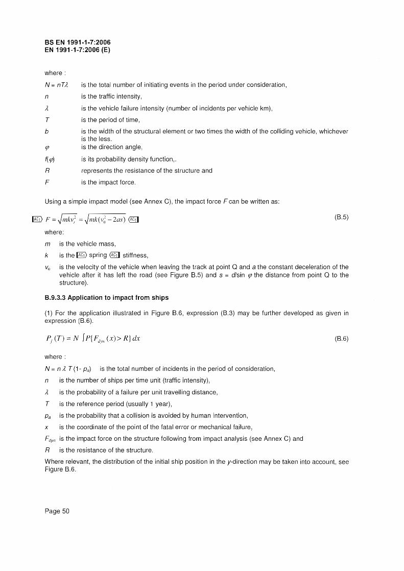
BS EN 1991-1-7:2006 EN 1991-1-7:2006 (E)
where:
N nTA
n
A
T
is the total number of initiating events in the period under consideration,
is the traffic intensity,
is the vehicle failure intensity (number of incidents per vehicle km),
is the period of time,
b is the width of the structural element or two times the width of the colliding vehicle, whichever is the less.
(jJ
f( (jJ)
R
F
is the direction angle,
is its probability density function,.
represents the resistance of the structure and
is the impact force.
Using a simple impact model (see Annex C), the impact force F can be written as:
[§) F = ~mkv,2 ~/nk(v~ - 2as)
where:
m is the vehicle mass,
k is the [§) spring stiffness,
(B.5)
Va is the velocity of the vehicle when leaving the track at point Q and a the constant deceleration of the vehicle after it has left the road (see Figure B.5) and s := dlsin (jJ the distance from point Q to the structure) .
8.9.3.3 Application to impact from ships
(1) For the application illustrated in Figure B.6, expression (B.3) may be further developed as given in expression (B.6).
(8.6)
where:
N nAT (1- Pa) is the total number of incidents in the period of consideration,
n is the number of ships per time unit (traffic intensity),
A is the probability of a failure per unit travelling distance,
T is the reference period (usually 1 year),
Pa is the probability that a collision is avoided by human intervention,
x is the coordinate of the point of the fatal error or mechanical failure,
Fdyn is the impact force on the structure following from impact analysis (see Annex C) and
R is the resistance of the structure.
Where relevant, the distribution of the initial ship position in the y-direction may be taken into account, see Figure B.6.
Page 50

Key
A: Object
B: Structu re
x=o
Figure B.6 - Ship collision scenario.
x
BS EN 1991-1-7:2006 EN 1991-1-7:2006 (E)
B.9.4 Guidance for application of risk analysis related to impact from rail traffic
(1) The following factors should be taken into account when assessing the risk to people from derailed trains on the approach to class A structures where the maximum permitted line speed is over 120 km/h and class B structures:
the likelihood of derailed trains on the approach to the structure.
the permissible speed of trains using the line.
the predicted deceleration of derailed trains on the approach to the structure.
the lateral distance a derailed train is predicted to travel.
whether the line is single or not in the vicinity of the structure.
the type of traffic (passenger/freight) passing under the structure.
the predicted number of passengers in the train passing under the structure.
the frequency of trains passing under the structure.
the presence of switches and crossings on the approach to the structure.
the static system (structural configuration) of the structure and the robustness of the supports.
the location of the supports to the structure relative to the tracks.
the predicted number of people, outside the train, who are at risk from harm from a derailed train.
The following factors also affect the risk from derailed trains, but to a lesser extent:
the curvature of the track in the vicinity of the structure.
the number of tracks, where there are more than two.
Page 51

BS EN 1991-1-7:2006 EN 1991-1-7:2006 (E)
The effect that any preventative and protective measures proposed have on other parts or other users of the adjacent infrastructure should also be taken into account. This includes for example the effect on signal sighting distances, authorised access, and other safety considerations relating to the layout of the track.
NOTE Further recommendations and guidance for class A and class B structures ~4.5.1.2 @il) are set out in UIC Code 777-2R (2002) "Structures Built Over Railway Lines (Construction requirements in the track zone).UIC Code 777-2R includes specific recommendations and guidance on the following:
carrying out a risk assessment for class B structures,
measures (including construction details) to be considered for class A structures, including situations where the maximum line speed at the site is less than 50 km/h,
measures to be considered for class A structures where the distance from the nearest structural support and the centre line of the nearest track is 3 m or less.
(2) The following should be considered for Class B structures either singly or in combination in determining the appropriate measures to reduce the risk to people from a derailed train on the approach to a structure:
provision of robustness to the supports of the structure to withstand the glancing impact from a derailed train to reduce the likelihood of collapse of the structure.
provision of continuity to the spans of the superstructure to reduce the likelihood of collapse following impact with the supports of the structure from a derailed train.
provision of measures to limit the lateral deviation of the derailed train on the approach to the structure to reduce the likelihood of impact from a derailed train.
provision of increased lateral clearance to the supports of the structure to reduce the likelihood of impact from a derailed train.
avoidance of supports located on a line that is crossed by a line extended in the direction of the turn out of a switch to reduce the likelihood of a derailed train being directed towards the supports of the structure.
provision of continuous walls or wall type supports (in effect the avoidance of supports consisting of separate columns) to reduce the likelihood of collapse following impact with the supports of the structure from a derailed train.
where it is not reasonably practicable to avoid supports consisting of separate columns provision of supports with sufficient continuity so that the superstructure remains standing if one of the columns is removed.
provision of deflecting devices and absorbing devices to reduce the likelihood of impact from a derailed train.
Page 52

C.1 General
Annex C (Informative) Dynamic design for impact
BS EN 1991·1·7:2006 EN 1991~1-7:2006 (E)
(1) Impact is an interaction phenomenon between a moving object and a structure, in which the kinetic energy of the object is suddenly transformed into energy of deformation. To find the dynamic interaction forces, the mechanical properties of both the object and the structure should be determined. Static equivalent forces are commonly used in design.
(2) Advanced design of structures to sustain actions due to impact may include explicitly one or several of the following aspects:
dynamic effects;
non linear material behaviour.
Only dynamic effects are dealt with in this annex.
NOTE For probabilistic aspects and analysis of consequences see Annex B.
(3) This annex provides guidance for the approximate dynamic design of structures subject to accidental impact by road vehicles, rail vehicles and ships, on the basis of simplified or empirical models.
NOTE 1 The models given in Annex C, in general, better approximate the design than the models presented in Annex B which in special cases might be too simplified.
NOTE 2 Analogous actions can be the consequence of impact in tunnels, on road barriers, etc. (see EN 1317). Similar phenomena may also arise as consequences of explosions (see Annex D) and other dynamic actions.
C.2lmpact dynamics
(1) Impact is characterised as either hard impact, where the energy is mainly dissipated by the impacting body, or soft impact, where the structure is designed to deform in order to absorb the impact energy.
C.2.1 Hard Impact
(1) For hard impact, the equivalent static forces may be obtained 'from 4.3 to 4.7. Alternatively, an approximate dynamic analysis may be performed following the simpli'fied approximations in C.2.1 (2) and (3).
(2) For hard impact it is assumed that the structure is rigid and immovable and that the colliding object deforms linearly during the impact phase. The maximum resulting dynamic interaction force is given by expression (C.1):
F=v r (C.1 )
where:
Vr is the object velocity at impact;
k is the equivalent elastic stiffness of the object (i.e. the ratio between force F and total deformation);
m is the mass of the colliding object.
The force due to impact may be considered as a rectangular pulse on the surface of the structure. In that case the duration of the pulse follows from:
53

Bs EN 1991-1-7:2006 EN 1991-1-7:2006 (E)
F I1t = ,.nv or I1t = .Jml k
If relevant, a non zero rise time can be applied (see Figure C.1).
(C.2)
When the colliding object is modelled as an equivalent impacting object of uniform cross-section (see Figure C.1) expressions (C.3) and (CA) should be used:
k = EAlL
m=pAL
where:
L is the length of the impacting object;
A is the cross sectional area;
E is the modulus of elasticity;
p is the mass density of the impacting object.
p~ A ~ E~ L
1..0 1
v, )
I ,'I ,I , I , I
I I
" I II
.J l ris'e tin1e
it f. - f'·'~'1 /...... t..:J.~ - .• ~, f , ~ ,.....
Figure C.1 -Impact model, F= dynamiC interaction force.
t
(C.3)
(CA)
(3) Expression (C.1) gives the maximum dynamic force value on the outer surface of the structure. Within the structure these forces may give rise to dynamic effects. An upper bound for these effects can be determined if the structure is assumed to respond elastically and the load is realised as a step function (i.e. a function that rises immediately to its final value and then stays constant at that value). In that case the dynamic amplification factor (i.e. the ratio between dynamic and static response) 'Pdyn is 2,0. If the pulse nature of the load (i.e. its limited time of application according to expression (C.2)) needs to be taken into account, calculations will lead to amplification factors 'Pdyn ranging from below 1,0 up to 1,8 depending on the dynamic characteristics of the structure and the object. In general, it is recommended to use a direct dynamic analysis to determine 'Pdyn with the loads specified in this annex.
C.2.2 Soft Impact
(1) If the structure is assumed elastic and the colliding object rigid , the expressions given in C.2.1 apply and should be used with k being the stiffness of the structure.
(2) If the structure is designed to absorb the impact energy by plastic deformations, provision should be made so that its ductility is sufficient to absorb the total kinetic energy Y2 m Vr 2 of the cOlliding object.
Page 54

BS EN 1991-1-7:2006 EN 1991-1-7:2006 (E)
(3) In the limit case of rigid-plastic response of the structure, the above requirement is satisfied by the condition of expression (C.5):
% m vr2
Yo (C.5)
where:
Fo is the plastic strength of the structure, i.e. the limit value of the static force F;
Yo is its deformation capacity, i.e. the displacement of the point of impact that the structure can undergo.
NOTE Analogous considerations apply to structures or other barriers specifically designed to protect a structure from impacts (see e.g. EN 1317 "Road restraint systems").
C.3 Impact from aberrant road vehicles
(1) In case of a lorry impacting a structural member, the velocity of impact Vr in expression (C.1) should be determined using expression (C.6):
(C.6)
where (see also Figure C.2):
Vo is the velocity of the lorry leaving the trafficked lane,
a is the average deceleration of the lorry after leaving the trafficked lane;
s is the distance 'from the point where the lorry leaves the trafficked lane to the structural member (see Figure C.2);
d is the distance from the centre of the trafficked lane to the structural member;
db is the braking distance = db = (v~ 12a) sin tp, where tp is the angle between the trafficked lane and
the course of the impacting vehicle.
(2) Indicative probabilistic information for the basic variables partly based on statistical data and partly on engineering judgement is given in Table C.1.
NOTE See also Annex B.
Page 55

BS EN 1991-1-7:2006 EN 1991-1-7:2006 (E)
Table C.1 - Indicative data for probabilistic collision force calculation.
Variable Designation Probability Mean value Standard distribution deviation
va vehicle velocity
- highway Lognormal 80 km/h 10 km/h
- urban area Lognormal 40 km/h 8 km/h
- courtyard Lognormal 15 km/h 5 km/h
- parking garage Lognormal 5 km/h 5 km/h
a Deceleration Lognormal 4,0 mIst; 1,3 mIst;
m I Vehicle mass - lorry Normal 20 000 kg 12 000 kg I
m ass car - - 1 500 kg --
k Vehicle stiffness Determ i n istic 300 kl\J/m --
<p Angle ~ Rayleigh @l] 10· 10"
(3) On the basis of Table C.1, the following approximate design value for the dynamic interaction force due to impact can be determined using expression (C.l):
where:
F 0 is the collision force
d and db are as before.
(C.l)
Indicative values for Fa and db are presented in Table C.2, together with design values for m and v. All these values correspond approximately to the averages given in Table C.1 plus or minus one standard deviation.
In particular cases, when specific information is available, different design values may be chosen, depending on the target safety, the traffic intensity and the accident frequency.
NOTE 1 The presented model is a rough schematisation and neglects at least in detail many influences that may play an important role like the presence of kerbs, bushes, fences and the cause of the incident. To some extent the scatter in the deceleration is supposed to compensate for those factors.
NOTE 2 Calculation of the dynamic impact force (Fd) using expression (C.?) may be modified on the basis of a risk analysis taking into account the potential consequences of an impact, the rate of deceleration, the tendency of the vehicle to deviate away from the carriageway, the likelihood of the vehicle leaving the carriageway and the likelihood of the vehicle hitting the structure.
(4) In the absence of a dynamic analysis, the dynamic amplification factor for the elastic response may be assumed to be equal to 1,4.
Page 56

BS EN 1991-1-7:2006 EN 1991-1-7:2006 (E)
NOTE The derived forces in this annex are intended to be used with an elasto-plastic dynamic structural analysis.
Table C.2 - Design values for vehicle mass, velocity and dynamic impact force Fo.
Type of road Mass Velocity Deceleration Impact force Distance
m Va A based on (C.1) db a
with Vr = Vo
Fa
[kg] [km/h] [m/s2] [kN] [m]
Motorways 30 000 90 3 2400 20
Urban areas 0 30 000 50 3 1 300 10
Courtyards
- cars only 1 500 20 3 120 2
- all vehicles 30 000 15 3 500 2
Parking garages
- cars only 1 500 10 3 60 1
a Road in areas where the speed limit is 50 km/h.
b The value of db may be multiplied by 0,6 for uphill slopes and by 1,6 for downhill slopes (see Figure C.2).
d Structure
~
~~/ / / ,I , /
/' / I / VQ /8
~ 1 /
£J1 ' Vehicfe
.,. ,,,/./ Road ,,"
---a. ___ .?-'~.'
.. d
Structure rz::=::::::!
Figure C.2 - Situation sketch for impact by vehicles (top view and cross sections for upward slope, flat terrain and downward slope).
Page 57

BS EN 1991-1-7:2006 EN 1991-1-7:2006 (E)
C.4 Impact by ships
C.4.1 Ship impact on inland waterways
(1) Impact by ships against solid structures on inland waterways should normally be considered as hard impact, with the kinetic energy being dissipated by elastic or plastic deformation of the ship itself.
(2) In the absence of a dynamic analysis, Table C.3 gives indicative values of the forces due to ship impact on inland waterways.
Table C.3 - Indicative values for the dynamic forces due to ship impact on inland waterways.
CEMTa Reference type of Length -I Massm Force Fdx c Force Fd/
Class ship
(ton) b (kN) (kN) (m)
I 30-50 200-400 2 000 1000
II 50-60 400-650 3 000 1 500
III "Gustav Konig" 60-80 650-1 000 4000 2 000
IV Class "Europe" 80-90 1 000-1 500 5 000 2500
Va Big ship 90-110 1 500-3 000 8 000 3500
Vb Tow + 2 barges 110-180 3 000-6 000 10 000 4 000
Via i Tow + 2 barges 110-180 3 000-6 000 10 000 4 000
Vlb Tow + 4 barges 110-190 6 000-12 000 14 000 5 000
Vic Tow + 6 barges 190-280 1 a 000-18 000 17 000 8 000
VII Tow + 9 barges 300 14 000-27 000 20 000 10 000
a CEMT: European Conference of Ministers of Transport, classification proposed 19 June 1992, approved by the Council of European Union 29 October 1993.
b The mass m in tons (1 ton = 1 000 kg) includes the total mass of the vessel, including the ship structure, the cargo and the fuel. It is often referred to as the displacement tonnage.
C The forces and include the effect of hydrodynamic mass and are based on background calculations, usinQ expected conditions for every waterway class.
(3) The indicative dynamic values given in Table C.3 may be adjusted depending upon the consequences of failure of the ship impact. It is recommended to increase these dynamic values for high consequences of failure and to reduce them in the case of low consequences of failure. See also 3.4.
(4) In the absence of a dynamic analysis for the impacted structure, it is recommended to multiply the indicative dynamic values given in Table C.3 by an appropriate dynamic amplification factor. Indeed, these values include the dynamic effects in the colliding object, but not in the structure. For information on dynamic analysis, see C.4.3. Indicative values of the dynamic amplification factor are 1,3 for frontal impact and 1,7 for lateral impact.
Page 58

BS EN 1991-1-7:2006 EN 1991-1-7:2006 (E)
(5) In harbour areas the forces given in Table C.3 may be reduced by a factor of 0,5.
C.4.2 Ship impact for sea waterways
(1) In the absence of a dynamic analysis, Table C.4 gives indicative values of the forces due to ship impact for sea waterways.
Table C.4 - Indicative values for the dynamic interaction forces due to ship impact for sea waterways.
Class of ship Length f= Mass rna Force Fdxb,c Force Fdy b, c
(m) (ton) (kN) (kN)
Small 50 3000 30000 15000
Medium 100 10000 80000 40000
Large 200 40000 240000 120000
Very large 300 100 000 460 000 230 000
The mass m in tons (1 ton = 1 000 kg) includes the total mass of the vessel, including the ship structure, the cargo and the fuel. It is often referred to as the displacement tonnage. It does not include the added hydraulic mass.
b The forces given correspond to a velocity of about 5,0 m/s. They include the effects of added hydraulic mass.
e Where relevant the effect of bulbs should be accounted for.
(2) In the absence of a dynamic analysis for the impacted structure, it is recommended to multiply the indicative dynamic values given in Table C.4 by an appropriate dynamic amplification factor. Indeed, these values include the dynamic effects in the colliding object, but not in the structure. For information on dynamic analysis, see C.4.3. Indicative values of the dynamic amplification factor are 1,3 for frontal impact and 1,7 for lateral impact.
(3) In harbour areas the forces given in Table C.4 may be reduced by a factor of 0,5.
(4) For side and stern impact it is recommended to multiply the forces given in Table C.4 by a factor of 0,3, mainly because of reduced velocities. Side impact may govern the design in narrow waters where head-on impact is not feasible.
C.4.3 Advanced ship impact analysis for inland waterways
(1) The dynamic impact force Fd may be derived from expressions (C.B) to (C.13). In this case, it is recommended to use the average mass value for the relevant ship class defined in Table C.3 and a design velocity Vrd equal to 3 m/s increased by the water velocity.
(2) Where a hydrodynamic mass has to be taken into account values of 10 % of the mass of displaced water for bow and 40 % for side impact are recommended.
(3) For elastic deformations (when Edef ::; 0,21 MNm) the dynamic design impact force may be calculated from expression (C.8):
Page 59

BS EN 1991-1-7:2006 EN 1991-1-7:2006 (E)
Fdyn,el = 10,95 . ~ Eilel' [MN] (C.B)
(4) For plastic deformations (when > 0,21 MNm), the dynamic design impact force may be calculated from expression (C.9):
= 5,0 . ~1 + 0,128 . Edef
[MN] (C.9)
The deformation energy [MNm] is equal to the available total kinetic energy Ea in case of frontal impact, while in case of lateral impact with angle a < 45°, a sliding impact may be assumed and the deformation energy taken equal to
Edef = Ea (1-cos a) (C.10)
(5) Information on probabilistic models of the basic variables determining the deformation energy or the ship's impact behaviour may be used for the design impact force based on probabilistic methods.
(6) If a dynamic structural analysis is used, the impact forces should be modelled as a half-sine-wave pulse for Fdyn< 5 MN (elastic impact) and a trapezoidal pulse for 5 fVIN (plastic impact); load durations and other details are presented in Figure C.3.
Page 60

5MN}
Key: tr elastic elapsing time [s]; tp plastic impact time [s]; te elastic response time [s]; ta equivalent impact time [s]; ts total impact time [s] for plastic impact ts tf + tp + te; c elastic stiffness of the ship (= 60 rvlN/m); Fa elastic-plastic limit force = 5 rvlN; Xe elastic deformation ("'" 0,1 m); Vn a) the sailing speed v" for frontal impact;
tr::;:.;.:.~tYI)
~~,::;:m· . FD
lc
BS EN 1991-1-7:2006 EN 1991-1-7:2006 (E)
b) velocity of the colliding ship normal to the impact point Vn = vr sin q. for lateral impact;
For frontal impact the mass m* to be taken into account is the total mass of the colliding ship/barge; for lateral impact: m* = (m1 + mhydr)/3, where m1 is the mass of the directly colliding ship or barge and mhyd is the hydraulic added mass.
Figure C.3 - Load-time function for ship collision, respectively for elastic and plastic ship response
(7) When a design value for the impact force is given, e.g. taken from Table C.3, and the load duration has to be calculated, the mass m* may be determined as follows:
Page 61

BS EN 1991-1-7:2006 EN 1991-1-7:2006 (E)
if Fdyn > 5 MN: by setting expression (C.9), equal to the kinetic energy Ea 0,5 m* vn2,
if .:; 5 MN :directly by m (Fdynlvn)2 * (1/c) [MN s2/m].
(8) When not specified by the project, a design velocity Vrd equal to 3 mls increased by the water velocity is recommended; in harbours the velocity may be assumed as 1,5 m/s. The angle a may be taken as 20°.
C.4.4 Advanced ship impact analysis for sea waterways
~ Text deleted @11 (1) The dynamic design impact force for sea-going merchant vessels between 500 Dead Weight Tons (DWT) and 300 000 DWT may be determined from expression (C.11):
Fbow jFO. L [ Eimp + ~.~.5 ·hLI.6
] 0.5
2.24· Fo [Eirnp L]
where:
L = Lpp 1275 m
Eilnp = Eimp 11425 .\1Nm
I ~ Eimp rn
2
and
Fbow is the maximum bow collision force in [MN];
Fa is the reference collision force = 210 MN;
·f E -L2.6 Jor imp 2:
- -2.6 forEil11p < L
Eimp is the energy to be absorbed by plastic deformations;
Lpp is the length of vessel in [m];
mx is the mass plus added mass with respect to longitudinal motion in [106 kg];
~ vr is the sailing speed (impact velocity) of the vessel, Vr = 5m/s (in harbours: 2,5 m/s) @11
(C.11 )
(2) Probabilistic models for basic variables determining the deformation energy or the ship's impact behaviour may be used where the determination of the design impact force is based on probabilistic methods.
(3) From the energy balance the maximum indentation Smax is determined using expression (C.12):
~ sillax (C.12)
(4) The associated impact duration, To, is represented by expression (C.13):
~ To 1.67 Srnax / Vr@1l (C.13)
(5) When not specified by the project a ~ sailing speed (impact velocity) vr@il equal to 5 mls increased by the water velocity is recommended; in harbours the velocity may be assumed as m/s.
Page 62

Annex D (Informative) Internal explosions
0.1 Dust explosions in rooms, vessels and bunkers
BS EN 1991-1-7:2006 EN 1991-1-7:2006 (E)
(1) The type of dust should normally be represented by a material parameter KSl! which characterises the confined explosion behaviour. Kst may be experimentally determined by standard methods for each type of dust.
I\lOTE 1 A higher value for Kst leads to higher pressures and shorter rise times for internal explosion pressures. The value of KSf depends on factors such as changes in the chemical composition, particle size and moisture content. Indicative values for KSf are given in Table 0.1.
Table D.1 - Kst values for dusts.
Type of dust Kst
(kN/m2 x m/s)
Brown coal 18 000
Cellulose 27 000
Coffee 9 000
Corn, corn crush 12 000
Corn starch 21 000
Grain 13 000
Milk powder 16 000
Mineral coal 13 000
Mixed provender 4 000
Paper 6 000
Pea flour 14 000
Pigment 29 000
Rubber 14 000
Rye flour, wheat flour 10 000
Soya meal 12 000
Sugar 15 000
Washing powder 27 000
Wood, wood flour 22 000
NOTE 2 In dust explosions, pressures reach their maximum value within a time span in the order of 20 to 50 ms. The decline to normal values strongly depends on the venting device and the geometry of the enclosure.
NOTE 3 See ~ ISO 6184-1 @il Explosion protection systems Part 1: Determination of explosion indices of combustible dusts in air.
(2) The venting area of cubic and elongated rooms, vessels, and bunkers for dust explosions within a single room may be determined using expression (0.1):
(0.1 )
where:
A is the venting area [m2]
Page 63

BS EN 1991-1-7:2006 EN 1991-1-7:2006 (E)
Pmax is the maximum pressure of the dust [kN/m2]
KSI is the deflagration index of a dust cloud [kN/m2 m S'l], see (1)
Pred.max is the anticipated maximum reduced pressure in the vented vessel [kN/m2]
Pstat is the static activation pressure with the size of existing venting areas [kN/m2]
V is the volume of room, vessel, bunker [m3].
Expression (0.1) is valid with the following restrictions:
HID:5 2, where H is the height and D the diameter of elongated room, vessel or bunker
10 kN/m2 :5 Pstat:5 100 kN/m2, rupture disks and panels with low mass which respond almost without intertia
10 kN/m2 :5 Pred.max :5 200 kN/m2
500 kN/m2 :5 Pmax :5 1000 kN/m2 for 1000 kN/m2 m S·l 5 Kst :5 30 000 kN/m2 m
respectively
500 kN/m2 :5 Pmax:5 1200 kN/m2 for 30 000 kN/m2 m S·l :5 Ks1 :5 80 000 kl\J/m2 m S·1.
(3) The venting area of a rectangular enclosure may be determined by using expression (0.2):
A = [ 4,485 x 10.8 X Pmax X KSI X PBem-
O•569 + 0,027(Pstat 1 0)PBem-O,5 ]
where:
A is the venting area [m2]
Pmax is the maximum pressure of the dust [kN/m2]
KSI is the deflagration index of a dust cloud [kN/m2 m S-1], see (1)
PBem is the design strength of the structure [kN/m2]
PSlat is the static activation pressure with the size of existing venting areas [kN/m2]
V is the volume of rectangular enclosure [m3].
Expression (0.2) is valid with the following restrictions:
(0.2)
L3IDE:5 2, where L3 is the greatest dimension of enclosure, dimensions of enclosure
2(Ll x L21 TT ,L1 and L2 are other
10 kN/m2 :5 Pstat:5 100 kN/m2, rupture disks and panels with low mass which respond almost without intertia
10 kN/m2 :5 Pred.max :5 200 kN/m2
500 kN/m2 :5 Pmax :5 1000 kN/m2 for 1000 kN/m2 m :5 Kst :::; 30 000 kN/m2 m S-1
respectively
500 kN/m2 :5 Pmax :5 1200 kN/m2 for 30 000 kN/m2 m :::; Kst :5 80 000 kN/m2 m S·1.
Page 64

BS EN 1991-1-7:2006 EN 1991-1-7:2006 (E)
(4) For elongated rooms with L3/0E ;;:: 2 the following increase for the venting area should be considered:
~AH A (- 4,30510g PBem + 9,368)log L3/0E (0.3)
where:
~AH is the increase for venting area [m2].
D.2 Natural gas explosions
(1) For buildings provided for having natural gas installed, the structure may be designed to withstand the effects of an internal natural gas explosion using a nominal equivalent static pressure given by expressions (0.4) and (0.5):
Pd= 3 + Pstat (0.4)
or
Pd= 3 + Pstatl 2 + 0,04 I (Av I \1)2 (0.5)
whichever is the greater,
where:
Pstat is the uniformly distributed static pressure at which venting components will fail, in (kN/m2);
Av is the area of venting components, in m2;
V is the volume of rectangular enclosure [m3].
Expressions (0.4) and (0.5) are valid for a room up to 1 000 m3 total volume.
NOTE The pressure due to deflagration acts effectively simultaneously on all of the bounding surfaces of the room.
(2) Where building components with different Pstat values contribute to the venting area, the largest value of Pstatshould be used. No value of Pd greater than 50 kN/m2 need be taken into account.
(3) The ratio of the area of venting components and the volume should comply with expression (0.6):
0,05 (11m) s AJVs 0,15 (0.6)
D.3 Explosions in road and rail tunnels
(1) In case of a detonation in road and rail tunnels, the pressure time function may be determined using expressions (0.7) to (0.9), see Figure 0.1 (a):
Page 65

as EN 1991-1-7:2006 EN 1991-1-7:2006 (E)
p{x,t) Po exp L lH 21~IJI to for li 11 s t s li 1 C2 [I C2 c]
p(x, t) 0 for all other conditions
where:
~ Po is the peak pressure (==2 000 kN/m2 for a typical liquefied natural gas fuel); @il
c1@il is the propagation velocity of the shock wave (~ 1 800 m/s);
~ c2@ilis the acoustic propagation velocity in hot gasses (- 800 m/s);
to is the time constant (= 0,01 s);
Ixl is the distance to the heart of the explosion;
is the time.
(0.7)
(0.8)
(0.9)
(2) In case of a deflagration in road and rail tunnels, the following pressure time characteristic may be taken into account, see Figure 01 (b):
t t p(t) = 4 Po (1 -) for ° S t s to
to to where:
~ Po is the peak pressure (=100 kN/m2 for a typical lique'fied natural gas fuel); @il
to is the time constant (== 0,1 s);
is the time.
(0.10)
(3) The pressure determined by expression (D.10) may be used for the entire interior surface of the tunnel.
0
Page 66
x x c[
X CJ
(a) p ..
Figure 0.1 - Pressure as a function of time for (a) detonation and (b) deflagration.

This page deliberately set blanh