EN 1906 - sel-electric.com · 8 tPr6 24 kV 1906 General descrIPtIon General PresentatIon TPR6 is an...
48
EN ED 1906
Transcript of EN 1906 - sel-electric.com · 8 tPr6 24 kV 1906 General descrIPtIon General PresentatIon TPR6 is an...
ENED 1906
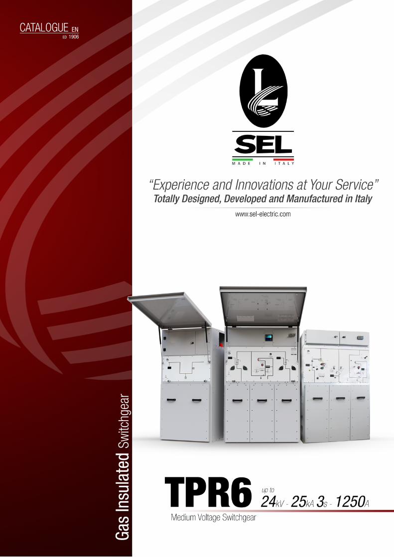
C+unit
+U+unit
+R+unit
+N4
unit
TPR6 24kV SeriesExpanding Range Solutions and Performances
TPR6 24kV SeriesExpanding Range Solutions and Performances

3www.sel-electric.comTPR6 24kV1906
• General Presentation 5Experience, Reliability and Continue Innovation 6
Developing 7
General Description 8
Applications 9
TPR6 Features 10
Quality 11
Internal Arc Proof 12
Outdoor Version IP54 - IP56 13
Indoor Version 14
Top Busbar Extensibility for outdoor and indoor versions 15
Indoor Lateral Extensibility 16
• TPR6 Main Characteristics 17• Main Components 18
Switch Disconnector 18
Switch Disconnector Operating Mechanism 18
Circuit Breaker 19
Circuit Breaker Operating Mechanism 20
TPR6 Standards 21
Technical Data 22
Functions 24
Outdoor Configurations 28
Indoor Configurations 29
• Components 31Voltage Indicator 32
HVSensor Voltage Detector 32
Operating Handle 33
Key Locking and Padlock 33
Fuses and Adaptor 34
Protection Relay and LV Marshalling Box 36
• Cable Connections 39Bushings - Cable Compartment - Termination Point 40
Cable Connection - Cable Terminal 41
Testing Cables Facility 42
Operating Sequences 43
Compatibility 44
Index

4 www.sel-electric.com TPR6 24kV1906

5www.sel-electric.comTPR6 24kV1906
General PresentatIon
Experience, Reliability and Continue Innovation 6
Developing 7
General Description 8
Applications 9
TPR6 Features 10
Quality 11
Internal Arc Proof 12
Outdoor Version IP54 - IP56 13
Indoor Version 14
Top Busbar Extensibility for outdoor and indoor versions 15
Indoor Lateral Extensibility 16

19066 www.sel-electric.com TPR6 24kV
SEL S.p.A. has over fifty years of experience in the construction of medium voltage switchgears.Today SEL S.p.A. offers a comprehensive range of products for medium voltage up to 40.5kV.
SEL S.p.A. offers advanced products that ensure maximum personal safety according to IEC-EN standards, providing internal arc protection as standard.
The TPR6 series, thanks to the various functional units, allow a wide modularity applicable to all types of requests in MV distribution, with ease of use and compactness.
exPerIence, relIabIlIty and contInue InnovatIon
General PresentatIon

1906
“Experience and Innovation at Your Service”
No Current Derating
up to
55°C
Outdoor
IP 54IP 56
IACup to
25kAA-FLR
up to
25kA3s
up to
24kVup to
630AC unitup to
1250A

8 www.sel-electric.com TPR6 24kV1906
General descrIPtIon
General PresentatIon
TPR6 is an SF6 insulated ring main unit for the secondary distribution network. TPR6 uses the latest developments in switchgear technology providing an extremely compact medium voltage switchgear solution and ensuring maximum personnel safety.
• Connection and power supply on a open or closed ring network.• Power supply and protection of transformers with circuit breaker or combined fuse-
switches up to 200A.• Power supply and protection of lines by a 1250A circuit breaker • Busbar coupling.• MV metering.• Earth switch for cable connection.
The robust design of the metal enclosure prevents deformations and ensures protection against fault. TPR6 is designed to withstand an internal arc caused by a rated short-circuit current up to 25kA for 1s preventing every danger to the operator.
The personnel safety is obtained by using mechanical interlocks:• When the switch disconnector is closed the earth switch can't be closed simultaneously
and the access to MV cables is prevented. • When the earth switch is closed there is a free access to MV cables but it is impossible to
close the switch.• When the access door to MV cables and fuses is opened it is impossible to close the
switch.Metal screens prevent access to electrical parts during maintenance operations. It is possible to block the switch in three positions with key locks.
TPR6 is a completely “sealed for life” system with a stainless steel tank containing all live parts and switching devices. This tank protects from the outside environment and ensures a high level of reliability as well as personal safety. The structure can withstand the electrodynamics stresses during the operation.The operating mechanism, movable mimic and voltage signaling lamps are positioned in the front panel. Switches are operated by means of spring-operated mechanisms.Movable mimic gives the position of the switch whereas the voltage signaling lamp indicates the presence of voltage. Fuses and cable compartment are easily accessible through the front door which is interlocked with the earth switch. If present, the low voltage auxiliary compartment is situated above the ring main unit.
IntroductIon
constructIon characterIstIcs
safety characterIstIcs
Internal arc classIfIcatIon
the tPr6 range consIsts of all of the necessary MV functIons enablIng:

9www.sel-electric.comTPR6 24kV1906
9www.sel-electric.comTPR6 24kV
TPR6 is a complete ring main unit range suitable for all the switching operations in 7.2kV, 12kV, 17.5kV, 24kV, secondary distribution network.Operating safely in a distribution network requires different switching points to obtain maximum service continuity in case of fault on the network.
• Power supply companies.• Power stations.• Cement industry.• Automotive industry.• Iron and steel works.• Windmills.• Solar plant.• Textile, paper and food industries.• Chemical industry.• Petroleum industry.
• Pipeline installations.• Offshore installations.• Electrochemical plants.• Petrochemical plants.• Seaport and shipbuilding industry.• Diesel power plants.• Emergency power supply installations.• Traction power supply systems.• Stadium and sport center.
aPPlIcatIons
General PresentatIon

190610 www.sel-electric.com TPR6 24kV
tPr6 Features
General PresentatIon
A wide range of products covering your present
and future requirements.
Modular cubicles adapted to future
extensions.
Possibility to mount auxiliary components
under voltage.
Options to anticipate the telecontrol.
During the testing cable operation it is not
needed to break the earthing busbar system
of the switchgear.
Interlock operated by earthing switch prevents
unsafe operations.Additional interlocks to prevent incorrect
operations.
All active parts of the TPR6 are contained in a sealed tank of stainless steel making it deal for installation in difficult ambient conditions.
Small dimensions and reduced weights
facilitate easy installation.
Solutions adapted to cable connection.
Simple operations.
All the control operations are carried out from
the front by means of a simple devices.
Small dimensions and reduced weights for easier handling and
installation.
Reduced civil works costs.
TPR6 has long service life.
Maintenance free live parts which are
integrated in vacuum or in a sealed tank of
stainless steal.
Control mechanisms are intended to function with
reduced maintenance under normal operating
conditions.
High level of electrical endurance when
breaking.
flexIbIlIty coMPact dIMensIons easy oPeratIons and MaInteInance
easy InstallatIon safety

190611www.sel-electric.comTPR6 24kV
All the manufacturing process follows a quality procedure certified by TÜV in accordance with ISO 9001:2015. The production conforms with the specific quality manual which is updated regularly so that it reflects the most recent applicable quality control procedures.
Systematic testsEach TPR6 undergoes a thorough check before leaving the factory. The following routine tests are performed according to IEC 62271-200 standard in order to guarantee the quality, reliability and safety of the product:• Measurement of the resistance of the main circuits.• Opening and closing speed measurement on switch, earth switch and circuit-breaker.• Operating torque measurement.• Filling pressure and tightness test.• Dielectric test.• Conformity with drawings and diagrams.• Electrical function test on auxiliary circuits.
The gas enclosure is manufactured with stainless steel and fabricated using automatic “robot welding” technique to produce consistent leak-free equipment.
QualIty
General PresentatIon

12 www.sel-electric.com TPR6 24kV1906
Internal arc ProoF uP to 25ka 1s
General PresentatIon
All SEL’s Switchgears series have Internal Arc test proof on the four sides (A-FLR) including cable box, in accordance with IEC62271-200
Concerning Internal arc capability, SEL designed and tested the MV switchgears in manner to drive the exhaust gas towards the bottom because it is the best solution for safety of operators.
Fault in busbar ductFault in SF6 gas tankFault in Cables compartment
SEL is able to meet customer's request for upward exhaust gas duct supplying a rear chimney that drives the gases outside. This chimney has been internal arc proof tested in C.E.S.I. Laboratory in Milan, at a fault current of 25kA 1s.During switchgear installation a suitable channel has to be arranged in order to collect the exhaust gas in a safe area.

13www.sel-electric.comTPR6 24kV1906
outdoor versIon IP54 uP to IP56General PresentatIon
The protection against severe weather conditions, rain, humidity and dust is guaranteed by TPR6 robust design. The protection degree of the switchgear is IP54. The enclosure is fitted with a front door and padlock. The gas piston facilitates the opening operation and maintains the door lifted in order to allow the normal operations or maintenance.
Rated current of the RMU is guaranteed with no derating up to 55°C ambient temperature.
Ck-Ck-kMk-LLk composition
NO Current Derating
up to 55°CIP 54Outdoor
IP 56Outdoor

14 www.sel-electric.com TPR6 24kV1906
Indoor versIon
General PresentatIon
R unit
IP 3Xup to
IP 41
LLCC unit

15www.sel-electric.comTPR6 24kV1906
toP busbar extensIbIlIty For outdoor and Indoor versIons
General PresentatIon
Realized with premoulded busbar system, no additional insulating belt is required.
"K" Extensibility connection is realized with bushing interface tipe "C" on the top of RMU. Both indoor/outdoor versions of TPR6 are suitable with this connection.
extensIble VersIon tyPe “K” for busbars.
connectIon wIth Pre-Mouled unshIelded busbar systeM uP to 17,5KV
connectIon wIth Pre-Mouled shIelded busbar systeM uP to 24KV
16 www.sel-electric.com TPR6 24kV1906
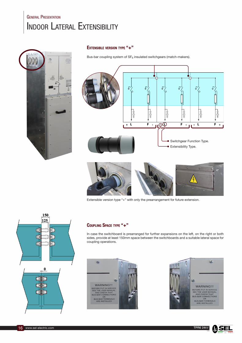
Indoor lateral extensIbIlIty
General PresentatIon
Bus-bar coupling system of SF6 insulated switchgears (match-makers).
In case the switchboard is prearranged for further expansions on the left, on the right or both sides, provide at least 150mm space between the switchboards and a suitable lateral space for coupling operations.
extensIble VersIon tyPe “+”
couPlIng sPace tyPe “+”
Extensible version type “+” with only the prearrangement for future extension.
Switchgear Function Type.
Extensibility Type.

17www.sel-electric.comTPR6 24kV1906
tPr6 MaIn characterIstIcs
Main Components 16
Switch Disconnector 16
Switch Disconnector Operating Mechanism 17
Circuit Breaker 18
Circuit Breaker Operating Mechanism 19
TPR6 Standards 20
TPR6 Technical Data 21
Functions 22
Indoor Configurations 29
Outdoor Configurations 30

18 www.sel-electric.com TPR6 24kV1906
Possible oPerating MechanisM accessories lt 3DPadlock holder for switch ●Padlock holder for earth switch ● ●Switch keylock (key removable in open position) ● ●Earth switch keylock (key removable in open position) ● ●Earth switch keylock (key removable in closed position) ● ●Switch auxiliary contacts ● ●Earth switch auxiliary contacts ● ●Shunt opening release ●Shunt closing Release ●Motor mechanism ● ●Door locking when earth switch is open ● ●
swItch dIsconnector
tPr6 MaIn characterIstIcs - MaIn coMPonents
TPR6 switch disconnector can be provided with two kind of operating mechanisms:
LT: Dead Point over-ride, operator indipendent operating mechanism capable of making, carrying and breaking load currents.
3D: Energy Stored, operator indipendent operating mechanism capable of making, carrying and breaking load currents.Operation in two steps: • Mechanism charging by lever or motor. • Stored energy released by opening/closing knob.
The insulation level inside the TPR6 modules has been obtained by means of sulphur hexafluoride (SF6). This gas has a double function: it increases dielectric rigidity in comparison with air and aids electric arc extinction. The modules with the equipment insulated in SF6, have the following advantages:• General and electrical long life.• Maintenance-free.• Secure and stable operation.• Reduced sizes.
This switchgear is made of a rotating part ( movable-contacts ) which opens and closes the electric circuit.
Positions: The switch disconnector has three positions:A) Closed B) OpenedC) Earthed
OPENEDCLOSED EARTHED
swItch dIsconnector

19www.sel-electric.comTPR6 24kV1906
cIrcuIt breaker
tPr6 MaIn characterIstIcs - MaIn coMPonents
Nowadays the interruption of current in vacuum is recognised as the dominant technology in medium voltage and as a consequence its use is continuously increasing. It is possible to have highly efficient vacuum circuit-breakers with electrical life which is longer than mechanical life, with total respect of environment; but in particular, vacuum circuit-breakers offer enhanced performances thanks to the reduction of arc energy, fast opening time, insulation recovery after overvoltage and reduction of mechanical energy needed for operating mechanism.
Our circuit breaker introduces the new concept of super-compact Disconnector + Vacuum CB combined device. It comprises of three vacuum interrupters, which have a fault-make, fault-break rating. Earthing of the outgoing cable is achieved by the use of the circuit breaker in series with the off-load earth disconnector.
CLOSED
SF6
VACUUM
OPENED
SF6
VACUUM
SF6
VACUUM
EARTHED
CLOSED
SF6
VACUUM
OPENED
SF6
VACUUM
SF6
VACUUM
EARTHED
CLOSED
SF6
VACUUM
OPENED
SF6
VACUUM
SF6
VACUUM
EARTHED
VacuuM technology
VacuuM cIrcuIt breaKer
scb6
cb6
scbd / cl-oP

20 www.sel-electric.com TPR6 24kV1906
cIrcuIt breaker oPeratInG MechanIsM
tPr6 MaIn characterIstIcs - MaIn coMPonents
The circuit breaker module operating mechanism SCB6 is composed of three different functional parts:1. Circuit Breaker Operating Mechanism Operator independent energy stored operating
mechanism with free release makes possible to carry out a complete cycle O-C-O with only one spring charging; besides it is suitable for the rapid auto-reclosing (O-0,3s-CO–3min-CO). The circuit-breaker can be remote controlled by installation of some electrical accessories.
2. Operator dependent line disconnector manual operating mechanism which operates in the absence of load.
3. Operator independent earth switch operating mechanism which operates under load.
The circuit breaker module operating mechanism SCBD is composed of three different functional parts:1. Circuit Breaker Operating Mechanism Operator independent energy stored operating
mechanism with free release makes possible to carry out a complete cycle O-C-O without spring charging; besides it is suitable for the rapid auto-reclosing (O-0,3s-CO–3min-CO). The circuit-breaker can be remote controlled by installation of some electrical accessories.
2. Operator dependent line disconnector manual operating mechanism which operates in the absence of load.
3. Operator dependent earth disconnector operating mechanism which operates in the absence of load.
The circuit breaker module operating mechanism CL-OP is composed of three different functional parts:1. Circuit Breaker Operating Mechanism Operator independent operating mechanism with
simplified closing system not intended for rapid auto-reclosing (CO–15s-CO). The circuit-breaker can be remote controlled by installation of some electrical accessories.
2. Operator dependent line disconnector manual operating mechanism which operates in the absence of load.
3. Operator dependent earth disconnector operating mechanism which operates in the absence of load.
SCB6 Frontal CoverCB6 Frontal Cover SCBD Frontal Cover CL-OP Frontal Cover
The circuit breaker module operating mechanism CB6 installed in the modules P is composed of three different functional parts:1. Circuit Breaker Operating Mechanism Operator independent energy stored operating
mechanism with free release makes possible to carry out a complete cycle O-C-O without spring charging; besides it is suitable for the rapid (O-0,3s-CO–3min-CO) reclosing cycle. The circuit-breaker can be remote controlled by means of some electrical accessories .
2. Operator dependent switch disconnector manual operating mechanism which operates in the absence of load.
3. Operator independent earth switch operating mechanism which operates under load.

21www.sel-electric.comTPR6 24kV1906
standards
tPr6 MaIn characterIstIcs - MaIn coMPonents
IEC StandardsTPR6 is manufactured and tested in conformity with the latest issues of the following IEC standards.
Iec 62271-1 High-voltage switchgear and controlgear - Part 1: Common specifications for alternating current switchgear and controlgear
Iec 62271-200 High-voltage switchgear and controlgear - Part 200: AC metal-enclosed switchgear and controlgear for rated voltages above 1 kV and up to and including 52 kV
Iec 62271-100 High-voltage switchgear and controlgear - Part 100: Alternating current circuit-breakers
Iec 62271-103 High-voltage switchgear and controlgear - Part 103: Switches for rated voltages above 1 kV up to and including 52 kV
Iec 62271-102 High-voltage switchgear and controlgear - Part 102: Alternating current disconnectors and earthing switches
Iec 62271-105 High-voltage switchgear and controlgear - Part 105: Alternating current switch-fuse combinations for rated voltages above 1 kV up to and including 52 kV
Iec 62271-206 High-voltage switchgear and controlgear - Part 206: Voltage presence indicating systems for rated voltages above 1 kV and up to and including 52 kV
Iec 61243-5 This part of IEC 61243 is applicable to voltage detecting systems that are single-pole and are capacitively-coupled to live parts. They are used to detect the presence or absence of operating voltage on a.c. electrical systems for voltages from 1 kV to 52 kV, and for frequencies from 162/3 Hz to 60 Hz.
Iec 62271-304 High-voltage switchgear and controlgear - Part 304: Design classes for indoor enclosed switchgear and controlgear for rated voltages above 1 kV up to and includuing 52 kV to be used in severe climatic conditions
Iec 62271-307 High-voltage switchgear and controlgear - Part 307: Guidance for the extension of validity of type tests of AC metal and solid-insulation enclosed switchgear and controlgear for rated voltages above 1 kV and up to and including 52 kV
Iec 60529 Degrees of protection provided by enclosures (IP Code)
Iec 60060-1 High-voltage test techniques - Part 1: General definitions and test requirements
Iec 60376 Specification of technical grade sulfur hexafluoride (SF6) for use in electrical equipment
Iec 62271-4 Handling procedures for sulphur hexafluoride ( SF6 ) and its mixtures
Iec 60255 Measuring relays and protection equipment
Iec 61869-2 Instrument transformers - Part 2: Additional requirements for current transformers
Iec 61869-3 Instrument transformers - Part 3: Additional requirements for inductive voltage transformers
Iec 60044-8 Instrument transformers - Part 8: Electronic current transformers
Iec 60282-1 High-voltage fuses - Part 1: Current-limiting fuses
dIn 43625 High-voltage fuses; Rated voltage 3,6 to 36 kV; Fuse-Links
en 50181 Plug-in type bushings above 1 kV up to 52 kV and from 250 A to 2,50 kA for equipment other than liquid filled transformer
ceI 0-16 Reference technical rules for the connection of active and passive consumers to the HV and MV electrical networks of distribution Company
22 www.sel-electric.com TPR6 24kV1906
technIcal data
tPr6 MaIn characterIstIcs
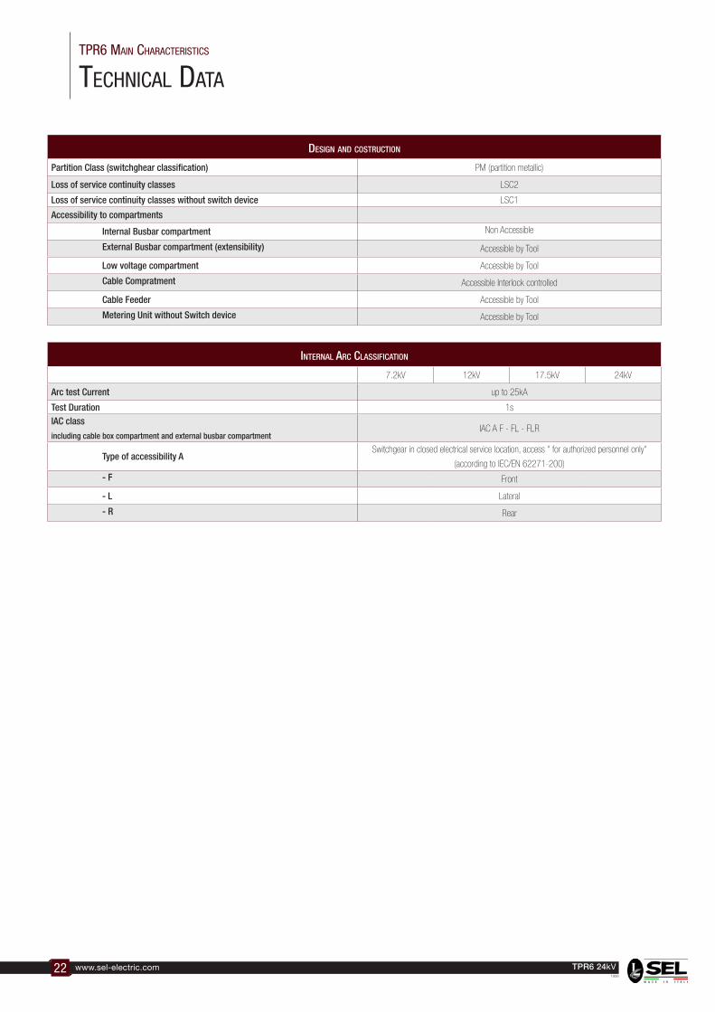
Design anD costruction
Partition Class (switchghear classification) PM (partition metallic)
Loss of service continuity classes LSC2
Loss of service continuity classes without switch device LSC1
Accessibility to compartments
Internal Busbar compartment Non Accessible
External Busbar compartment (extensibility) Accessible by Tool
Low voltage compartment Accessible by Tool
Cable Compratment Accessible Interlock controlled
Cable Feeder Accessible by Tool
Metering Unit without Switch device Accessible by Tool
internal arc classification
7.2kV 12kV 17.5kV 24kV
Arc test Current up to 25kA
Test Duration 1s
IAC class
including cable box compartment and external busbar compartmentIAC A F - FL - FLR
Type of accessibility ASwitchgear in closed electrical service location, access " for authorized personnel only"
(according to IEC/EN 62271-200)
- F Front
- L Lateral
- R Rear
23www.sel-electric.comTPR6 24kV1906
tPr6 MaIn characterIstIcs
technIcal data
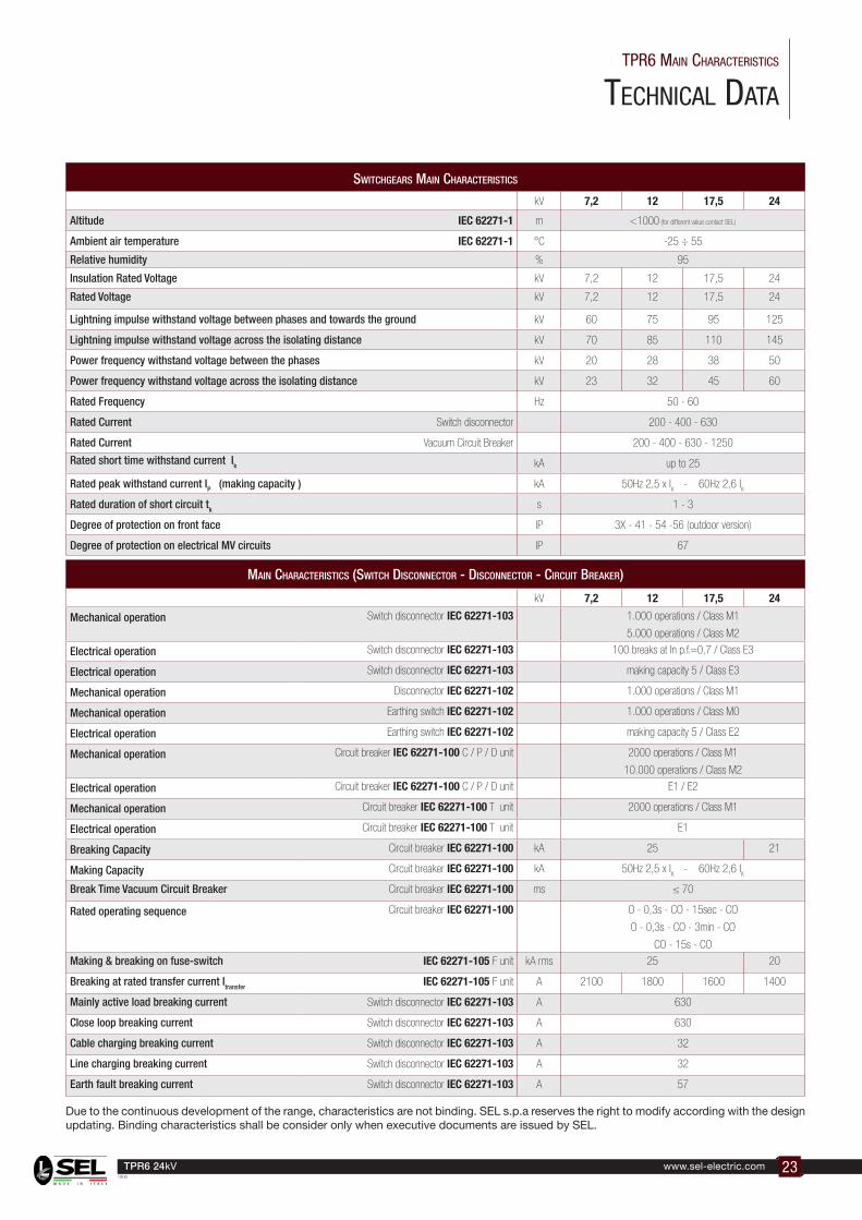
switchgears Main characteristics
kV 7,2 12 17,5 24
Altitude IEC 62271-1 m <1000 (for different value contact SEL)
Ambient air temperature IEC 62271-1 °C -25 ÷ 55
Relative humidity % 95
Insulation Rated Voltage kV 7,2 12 17,5 24
Rated Voltage kV 7,2 12 17,5 24
Lightning impulse withstand voltage between phases and towards the ground kV 60 75 95 125
Lightning impulse withstand voltage across the isolating distance kV 70 85 110 145
Power frequency withstand voltage between the phases kV 20 28 38 50
Power frequency withstand voltage across the isolating distance kV 23 32 45 60
Rated Frequency Hz 50 - 60
Rated Current Switch disconnector 200 - 400 - 630
Rated Current Vacuum Circuit Breaker 200 - 400 - 630 - 1250
Rated short time withstand current Ik kA up to 25
Rated peak withstand current IP (making capacity ) kA 50Hz 2,5 x IK
- 60Hz 2,6 IK
Rated duration of short circuit tk s 1 - 3
Degree of protection on front face IP 3X - 41 - 54 -56 (outdoor version)
Degree of protection on electrical MV circuits IP 67
Main characteristics (switch Disconnector - Disconnector - circuit breaker)
kV 7,2 12 17,5 24
Mechanical operation Switch disconnector IEC 62271-103 1.000 operations / Class M1
5.000 operations / Class M2
Electrical operation Switch disconnector IEC 62271-103 100 breaks at In p.f.=0,7 / Class E3
Electrical operation Switch disconnector IEC 62271-103 making capacity 5 / Class E3
Mechanical operation Disconnector IEC 62271-102 1.000 operations / Class M1
Mechanical operation Earthing switch IEC 62271-102 1.000 operations / Class M0
Electrical operation Earthing switch IEC 62271-102 making capacity 5 / Class E2
Mechanical operation Circuit breaker IEC 62271-100 C / P / D unit 2000 operations / Class M1
10.000 operations / Class M2
Electrical operation Circuit breaker IEC 62271-100 C / P / D unit E1 / E2
Mechanical operation Circuit breaker IEC 62271-100 T unit 2000 operations / Class M1
Electrical operation Circuit breaker IEC 62271-100 T unit E1
Breaking Capacity Circuit breaker IEC 62271-100 kA 25 21
Making Capacity Circuit breaker IEC 62271-100 kA 50Hz 2,5 x IK
- 60Hz 2,6 IK
Break Time Vacuum Circuit Breaker Circuit breaker IEC 62271-100 ms ≤ 70
Rated operating sequence Circuit breaker IEC 62271-100 O - 0,3s - CO - 15sec - CO
O - 0,3s - CO - 3min - CO
CO - 15s - CO
Making & breaking on fuse-switch IEC 62271-105 F unit kA rms 25 20
Breaking at rated transfer current Itransfer IEC 62271-105 F unit A 2100 1800 1600 1400
Mainly active load breaking current Switch disconnector IEC 62271-103 A 630
Close loop breaking current Switch disconnector IEC 62271-103 A 630
Cable charging breaking current Switch disconnector IEC 62271-103 A 32
Line charging breaking current Switch disconnector IEC 62271-103 A 32
Earth fault breaking current Switch disconnector IEC 62271-103 A 57
Due to the continuous development of the range, characteristics are not binding. SEL s.p.a reserves the right to modify according with the design updating. Binding characteristics shall be consider only when executive documents are issued by SEL.

24 www.sel-electric.com TPR6 24kV1906
tPr6 unIts FunctIons
tPr6 MaIn characterIstIcs
Unit Name:c
Unit Function:Line Feeder with CB
Device:630A Circuit Breaker + Disconnector with Earth Disconnector
Unit Name:l
Unit Function:Network Switch Disconnector
Device:630A Switch Disconnectorwith Earthing Switch
Unit Name:t
Unit Function:Transformer Feeder with CB
Device:200A Circuit Breaker + Disconnector with Earth Disconnector
Unit Name:F
Unit Function:Transformer Feeder with Fuse-Switch Disconnector
Device:200A Combined Fuse-Switch Disconnector with Earthing Switch
Unit Name:d
Unit Function:Line Feeder with CB
Device:1250A Circuit Breaker + Disconnector with Earthing Switch-Disconnector
Unit Name:G
Unit Function:Network Coupling with Circuit Breaker + Disconnector
Device:630A Circuit Breaker + Disconnector with Earth Disconnector
G unit
F unit
L unit
D unit
T unit
C unit
Details
Details
Details
Details
Details
Details
25www.sel-electric.comTPR6 24kV1906
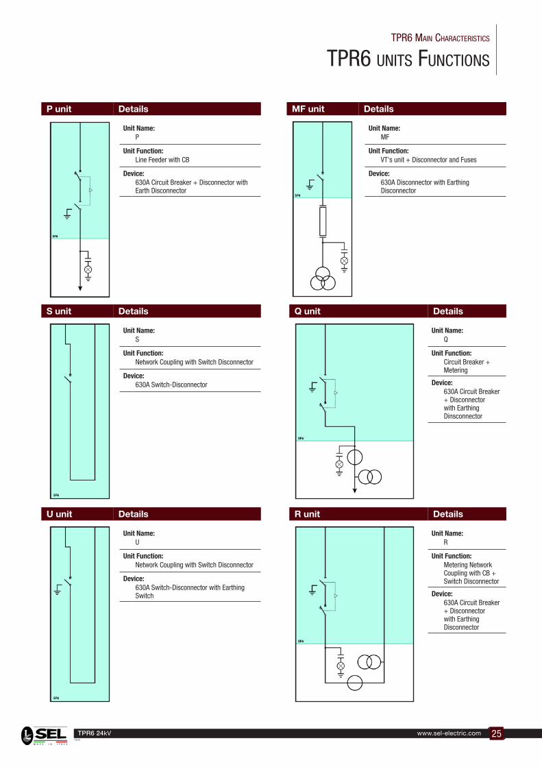
tPr6 unIts FunctIons
tPr6 MaIn characterIstIcs
Unit Name:P
Unit Function:Line Feeder with CB
Device:630A Circuit Breaker + Disconnector with Earth Disconnector
Unit Name:s
Unit Function:Network Coupling with Switch Disconnector
Device:630A Switch-Disconnector
Unit Name:u
Unit Function:Network Coupling with Switch Disconnector
Device:630A Switch-Disconnector with Earthing Switch
Q unit
R unit
Unit Name:Q
Unit Function:Circuit Breaker + Metering
Device:630A Circuit Breaker + Disconnector with Earthing Dinsconnector
Unit Name:r
Unit Function:Metering Network Coupling with CB + Switch Disconnector
Device:630A Circuit Breaker + Disconnector with Earthing Disconnector
U unit
S unit
P unit
Details
Details
Details
Details
Details
Unit Name:MF
Unit Function:VT's unit + Disconnector and Fuses
Device:630A Disconnector with Earthing Disconnector
MF unit Details

26 www.sel-electric.com TPR6 24kV1906
tPr6 unIts FunctIons
tPr6 MaIn characterIstIcs
N1 unit N2 unit
Unit Name:n1
Unit Function:Metering Unit + Switch Disconnector
Device:630A Switch-Disconnector with Earthing Switch
Unit Name:n2
Unit Function:Metering Unit + Switch Disconnector
Device:630A Switch-Disconnector with Earthing Switch
Unit Name:n3
Unit Function:Metering Unit + Switch Disconnector
Device:630A Switch-Disconnector with Earthing Switch
Unit Name:n4
Unit Function:Metering Unit + Switch Disconnector
Device:630A Switch-Disconnector with Earthing Switch
N3 unit N4 unitDetails Details
Details Details
Unit Name:I1 - I2 - I3
Unit Function:Cable Connection
Device:-
I1 - I2 - I3 units Details
the "I" unIt Is only avaIlable In coMbInatIon wIth another unIt, For exaMPle "I1c" or "I1lc"
I unIt Is dIvIded Into 3 tyPoloGIes:
"I1" = 3 bushInGs
"I2" = 6 bushInGs
"I3" = 9 bushInGs
exaMPle oF "I3c" unIt
27www.sel-electric.comTPR6 24kV1906
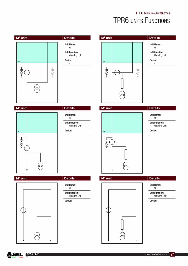
tPr6 unIts FunctIons
tPr6 MaIn characterIstIcs
M1 unit M2 unit
Unit Name:M1
Unit Function:Metering Unit
Device:-
Unit Name:M2
Unit Function:Metering Unit
Device:-
Unit Name:M5
Unit Function:Metering Unit
Device:-
Unit Name:M3
Unit Function:Metering Unit
Device:-
Unit Name:M6
Unit Function:Metering Unit
Device:-
Unit Name:M4
Unit Function:Metering Unit
Device:-
M5 unit
M3 unit
M6 unit
M4 unit
Details
Details
Details
Details
Details Details
28 www.sel-electric.com TPR6 24kV1906
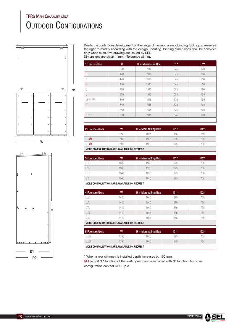
* When a rear chimney is installed depth increases by 150 mm.
The first "L" function of the switchgear can be replaced with "I" function, for other
configuration contact SEL S.p.A.
1 function unit w H + Marshalling box D1* D2*
L 390 1915 675 760
G 470 1915 675 760
C 470 1915 675 760
T 470 1915 675 760
S 470 1915 675 760
U 470 1915 675 760
M 1-2-3-4-5-6 840 1915 675 760
Q 840 1915 675 760
R 840 1915 675 760
N 1-2-3-4 840 1915 675 760
2 functions units w H + Marshalling Box D1* D2*
LL 740 1915 675 760
LT 740 1915 675 760
LC 740 1915 675 760
MORE CONFIGURATIONS ARE AVAILABLE ON REQUEST
3 functions units w H + Marshalling Box D1* D2*
LLL 1090 1915 675 760
LCL 1090 1915 675 760
LTL 1090 1915 675 760
LTT 1090 1915 675 760
MORE CONFIGURATIONS ARE AVAILABLE ON REQUEST
4 functions units w H + Marshalling Box D1* D2*
LLLL 1440 1915 675 760
LLTL 1440 1915 675 760
LTTL 1440 1915 675 760
LLCL 1440 1915 675 760
LCCL 1440 1915 675 760
MORE CONFIGURATIONS ARE AVAILABLE ON REQUEST
5 functions units w H + Marshalling Box D1* D2*
LLLLL 1790 1915 675 760
LLLLT 1790 1915 675 760
MORE CONFIGURATIONS ARE AVAILABLE ON REQUEST
outdoor conFIGuratIons
tPr6 MaIn characterIstIcs
w
h
D1
D2
Due to the continuous development of the range, dimension are not binding. SEL s.p.a. reserves the right to modify according with the design updating. Binding dimensions shall be consider only when executive drawing are issued by SEL.Dimensions are given in mm - Tolerance ±5mm.

29www.sel-electric.comTPR6 24kV1906
Indoor conFIGuratIons
tPr6 MaIn characterIstIcs
1 function unit w h1 h2not extensible
h lV Marshalling box
D1* D2*
L 390 1470 - 120 - 300 - 450 675 760
F 390 1470 - 120 - 300 - 450 675 760
G 470 1470 - 120 - 300 - 450 675 760
C 470 1470 - 120 - 300 - 450 675 760
T 470 1470 - 120 - 300 - 450 675 760
S 470 1470 - 120 - 300 - 450 675 760
U 470 1470 - 120 - 300 - 450 675 760
M 1 - 2 - 3 - 4 - 5 - 6 840 1470 - 120 - 300 - 450 675 760
Q 840 1470 - 120 - 300 - 450 675 760
R 840 1470 - 120 - 300 - 450 675 760
N 1 - 2 - 3 - 4 840 1470 - 120 - 300 - 450 675 760
D 600 1470 - 120 - 300 - 450 675 760
P 470 1470 - 120 - 300 - 450 675 760
MF 390 1470 - 120 - 300 - 450 675 760
EYEBOLTS ARE REMOVABLE
3 functions units w h1 h2not extensible
h lV Marshalling box
D1* D2*
LLL 1090 1470 1200 120 - 300 - 450 675 760
LCL 1090 1470 - 120 - 300 - 450 675 760
LTL 1090 1470 1200 120 - 300 - 450 675 760
LLF 1090 1470 - 120 - 300 - 450 675 760
LTT 1090 1470 - 120 - 300 - 450 675 760
MORE CONFIGURATIONS ARE AVAILABLE ON REQUEST - EYEBOLTS ARE REMOVABLE
5 functions units w h1 h2not extensible
h lV Marshalling box
D1* D2*
LLLLL 1790 1470 1200 120 - 300 - 450 675 760
LLLLT 1790 1470 1200 120 - 300 - 450 675 760
MORE CONFIGURATIONS ARE AVAILABLE ON REQUEST - EYEBOLTS ARE REMOVABLE
4 functions units w h1 h2not extensible
h lV Marshalling box
D1* D2*
LLLL 1440 1470 1200 120 - 300 - 450 675 760
LLTL 1440 1470 1200 120 - 300 - 450 675 760
LLLF 1440 1470 - 120 - 300 - 450 675 760
LTTL 1440 1470 - 120 - 300 - 450 675 760
LLCL 1440 1470 - 120 - 300 - 450 675 760
LCCL 1440 1470 - 120 - 300 - 450 675 760
MORE CONFIGURATIONS ARE AVAILABLE ON REQUEST - EYEBOLTS ARE REMOVABLE
6 functions units w h1 h2not extensible
h lV Marshalling box D1* D2*
LLLLLL 2140 1470 1200 120 - 300 - 450 675 760
LLLLLT 2140 1470 1200 120 - 300 - 450 675 760
LLLLLC 2140 1470 - 120 - 300 - 450 675 760
MORE CONFIGURATIONS ARE AVAILABLE ON REQUEST - EYEBOLTS ARE REMOVABLE
2 functions units w h1 h2not extensible
h lV Marshalling box
D1* D2*
LL 740 1470 1200 120 - 300 - 450 675 760
LT 740 1470 1200 120 - 300 - 450 675 760
LF 740 1470 - 120 - 300 - 450 675 760
LC 740 1470 - 120 - 300 - 450 675 760
MORE CONFIGURATIONS ARE AVAILABLE ON REQUEST - EYEBOLTS ARE REMOVABLE
w
h1h
lV
D1
D2
h2
not extensible
* When a rear chimney is installed depth increases by 150 mm.
The first "L" function of the switchgear can be replaced with "I" function, for other
configuration contact SEL S.p.A.
Due to the continuous development of the range, dimension are not binding. SEL s.p.a. reserves the right to modify according with the design updating. Binding dimensions shall be consider only when executive drawing are issued by SEL.Dimensions are given in mm - Tolerance ±5mm.

30 www.sel-electric.com TPR6 24kV1906
31www.sel-electric.comTPR6 24kV1906
coMPonents
Voltage Indicator 32
HVSensor Voltage Detector 32
Operating Handle 33
Key Locking and Padlock 33
Fuses and Adaptor 34
Protection Relay 36
Marshalling Box (Low voltage Panel) 36

32 www.sel-electric.com TPR6 24kV1906
voltaGe IndIcator - hvsensor
coMPonents
Voltage IndIcator
Voltage presence indicating system. Integrated 3-phase test point for phase comparison test.
The Voltage Presence Indicating System (VPIS) SELCompliant with the standard IEC 62271-206, allows to display the voltage presence of the three phases by means an LCD, and to do a phase-concordance test between two lines, on all the SEL S.p.A. switchboards indoor and outdoor.
The voltage presence is indicated by the appearance on the display of the symbol
According to the standard IEC 62271-206, the indication will appear for voltages (line-to-earth) greater than 45% of the minimum rated voltage Unmin, and will completely disappear for voltages (line-to-earth) less than 10% of the maximum rated voltage Unmax. By Un we mean the line voltage (phase-to-phase) applied to the switchboard.
Ø4 mm connecting point to perform a phase concordance test
Earth connection point
VP for L2 phase
VP for L1 phase
VP for L3 phase
Electric Diagram
L1 L2 L3
Rated Medium VoltageUn
C
C
C
C = Capacitivecoupling element
hVsensor Voltage detector
Voltage detectIng systeM accordIng to Iec 61243-5
Phase coMParIson test unIt MaKe PfI sterer, tyPe ePV
Voltage detector with relay output. Use in combination with Voltage Indicator.
Integrated voltage indicator VOIS+, VOIS R+
as combined test unit (HR and LRM) for:– Voltage detection– Phase comparison– Interface test– Integrated self-test– Indication via LED.

33www.sel-electric.comTPR6 24kV1906
Padlock holders can be installed in both switch disconnectors and earthing switches as optionals.
Keylock can be installed in both switch disconnectors and earthing switches as optionals.
PadlocK holder
KeylocK
In the TPR6 switchgear there is a single operating handle for all mechanism.
For F unit there is a special operating handle only to remove the fuses.
oPeratIng handle
Operating Handle - Keylocks and Padlock HoldercoMPonents

34 www.sel-electric.com TPR6 24kV1906
Fuse selectionSome important transformer and fuse features have to be known to select the right fuse for power transformer protection:
Transformer:Rated power Pn [kVA]Short circuit voltage Ucc [%]Service rated voltage Un [kV]Rated current Int [A]Inrush maximum current Ii [A] (usually 12xInt)Overload current Is [A] (usually 1,5xInt)Short circuit current ICCt [A]Maximum time withstand short circuit tm [s] (usually 2s for transformer up to 630kVA, 3s for bigger transformer)
FuseRated insulation voltage Vi [kV]Rated current In [A]Maximum breaking current I1 [kA]Minimum breaking current I3 [A]Power losses at Int PW [W]
Time/current characteristic to get follow values:Pre-arcing current at 0,1s If (t=0,1s)[A] Pre-arcing current at tm If (t=tm)[A]Pre-arcing current at 0,05s If (t=0,05s)[A]
Verify following conditions:• The rated insulation voltage of the fuse has to be higher than the service rated voltage of
the transformer Vi > Un • The fuse has to be able to break the maximum short circuit current of the plant I1 > ICCt (in
case of fault before the transformer)• The fuse melts in case of fault on LV wiring of the transformer I3 < ICCt
• The fuse protects the transformer in case of short circuit If (tm) < ICCt • The fuse does not melt at the transformer withstand overload In > IS • The fuse does not melt at the transformer inrush current If (0,1s) > Ii • The fuse power dissipation does not compromise the temperature inside the switchboard
PW < 150W• The transfer current has to be lower then the maximum admissible value for the switchboard
If (0,05s) < Itransfer
StandardStriker pin fuses (1 ± 0.25 Joule) in accordance with:• IEC 60 282-1/VDE 0670-4 • IEC 60 787/VDE 0670-402• DIN 43 625Selection table helps to select the fuses for generic MV/LV power transformers; it is valid for ambient air temperature up to 40°C and it has to be verified with all above parameters.
fuses selection table - tabella scelta fusibili
Vs Vi Pn [kVa]
[kV] [kV] 100 125 160 200 250 315 400 500 630 800 1000 1250 1600 2000
6 12 20 25 31,5 40 50 63 80 100 125 160 - - - -
6,6 12 16 20 25 31,5 40 50 63 80 100 125 160 - - -
10 12 16 16 20 25 31,5 40 50 63 80 100 125 160 - -
11 12 16 16 16 20 25 31,5 40 50 63 80 100 125 160 -
15 24 10 10 16 16 20 25 31,5 40 50 63 80 100 125 -
20 24 6 10 10 16 16 20 25 31,5 40 50 63 80 100 125
23 24 6 6 10 10 16 16 20 25 31,5 40 50 63 80 100
33 36 4 6 6 10 10 10 16 20 25 31,5 40 40 50 63
36 36 4 6 6 10 10 10 16 16 20 25 31,5 40 50 63
Standard fuses
Special fuses up to 12kV
Special fuses up to 24kV
FusescoMPonents
35www.sel-electric.comTPR6 24kV1906
FusescoMPonents
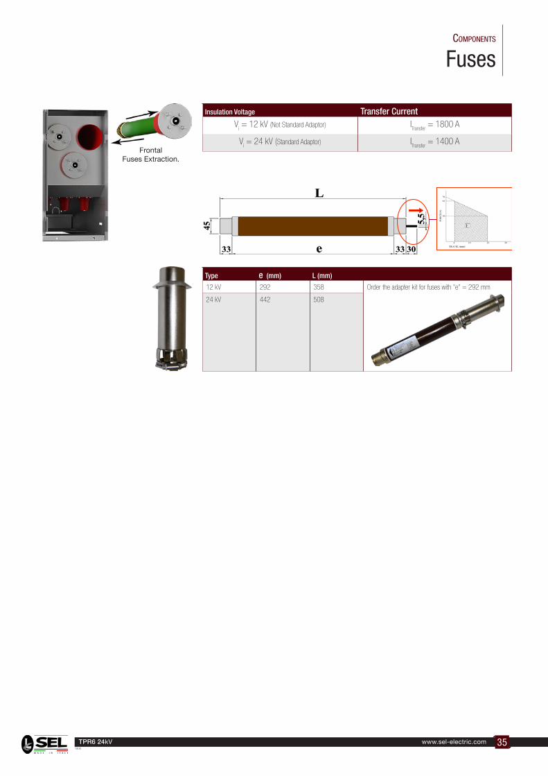
Type e (mm) L (mm)
12 kV 292 358 Order the adapter kit for fuses with "e" = 292 mm
24 kV 442 508
Insulation Voltage Transfer CurrentV
i = 12 kV (Not Standard Adaptor) I
Transfer = 1800 A
Vi = 24 kV (Standard Adaptor) I
Transfer = 1400 A
Frontal Fuses Extraction.

36 www.sel-electric.com TPR6 24kV1906
ProtectIon relay - MarshallInG box low voltaGe Panel
coMPonents
TPR6 range can be provided with self-powered protection relays with ring core CTs on cables or protection relays with power supply. All the relays used are well-known brands with high level of safety and reliability.In some cases the protection relay is installed directly on board of the circuit breaker, in other cases when the protection relay dimensions are bigger or when the wiring diagram is more complex, the protection relay is installed in the LV compartment located on the top or in front of the switchgear.
In case of big dimensions of the auxiliary equipment or complex wiring diagram, TPR6 can be provided with the auxiliary modules located in the lateral side of the switchgear.
Relay installed in white frontal panel Small LV marshalling box installed on top of RMU
Relay installed in LV marshalling box indoor version
Relay installed in LV marshalling box outdoor version

37www.sel-electric.comTPR6 24kV1906
coMPonents
note

38 www.sel-electric.com TPR6 24kV1906
39www.sel-electric.comTPR6 24kV1906
cable connectIons
Bushings - Cable Compartment - Termination Point 42
Cable Connection - Cable Terminal 43
Testing Cable Facilities 44
Operating Sequences 45
Compatibility 46

40 www.sel-electric.com TPR6 24kV1906
bushInGs - cable coMPartMent - terMInatIon PoInt
tyPe a 250a
tyPe c 630a
cable connectIons
units
Unit Function L F C P T DBushing Type C A C C C C
Epoxy resin bushings installed on TPR6 are according to DIN EN 50181.
bushIngs
cable bushIngs heIght outdoor cable bushIngs heIght Indoor ( not extensIble and uPPer extensIble VersIon "K" )
f unitP unit
cable bushIngs heIght Indoor ( extensIble VersIon tyPe "+" )
f unitP unit
cable bushIngs heIght Indoor
h1200 tyPe ( not extensIble )

41www.sel-electric.comTPR6 24kV1906
cable connectIon - cable terMInal cable connectIons
B
A
A 243B 370
Pre-mouled shielded type termination for interface “C” bushing (according with DIN EN 50181 standard) are suitable cable termination.
Standard air insulated heat/cold shrinkable indoor termination can be used in combination with silicon cover caps (premoulded boots) placed on the “C” bushing sealed and fixed by cast resin bolts. It allows access for cable test purpose. Using our own production silicon pre-mouled boots, this solution has been tested by C.E.S.I. Laboratory in Milan Italy.
250A Straight Cable
ConnectorBushing type A
For "F" unit is possible to install only this connector.
630A Disconnectable and bolted socket Connector Bushing type C
cables terMInal
cable connectIon

42 www.sel-electric.com TPR6 24kV1906
testInG cables FacIlItIes
cable connectIons
tewstIng cable facIlIIes
wIth Pre-Mouled shIelded cable connector
wIth Pre-Mouled not screened cable connector (Made by sel s.P.a.)
The TPR6 has fully interlocked integrated ring switch and tee-off cable test facilities.To perform the testing cable remove the insulating cap from the cable connector and install the testing probe.
1
1
3
3
2
2
4
4

43www.sel-electric.comTPR6 24kV1906
oPeratIon seQuences
TPR6 - SCBD Operating MechanismThe video shows the switch operations sequences of the SCBD Operating Mechanism mounted on a C - Q - R - G units.
TPR6 - 3D Operating MechanismThe video shows the switch operations sequences of the 3D Operating Mechanism mounted on a F units.
TPR6 - LT Operating MechanismThe video shows the switch operations sequences of the LT Operating Mechanism mounted on a L - S - U - N units.
TPR6 - SCBD Testing CablesThe video shows the switch operations sequences for testing cables of the SCBD Operating Mechanism mounted on a C - Q - R - G units.
TPR6 - CLOP Testing CablesThe video shows the switch operations sequences for testing cables of the CLO Operating Mechanism mounted on a C - T units.
TPR6 - LT Testing CablesThe video shows the switch operations sequences for testing cables of the LT Operating Mechanism mounted on a L - S - U - N units.
TPR6 - CLOP Operating MechanismThe video shows the switch operations sequences of the CLOP Operating Mechanism mounted on a C - T units.In the video there is a LTL operating sequences
unIts oPeratIng sequences
Qr Code usage istructions:Download the right application from your device store to read QR-Code marks.Start Application.Point your device camera to the QR Code.Multimedia information will be downloaded direcly to your device.
TPR6 - CB6/SCB6 Op. MechanismThe video shows the switch operations sequences of the CB6 and SCB6 Operating Mechanism mounted on a P and D unit.
44 www.sel-electric.com TPR6 24kV1906
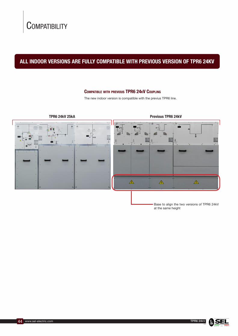
coMPatIbIlIty
Base to align the two versions of TPR6 24kV at the same height
The new indoor version is compatible with the previus TPR6 line.
Previous TPR6 24kVTPR6 24kV 25kA
coMPatIble wIth PreVIous tPr6 24KV couPlIng
all Indoor VersIons are fully coMPatIble wIth PreVIous VersIon of tPr6 24KV

45www.sel-electric.comTPR6 24kV1906
note

46 www.sel-electric.com TPR6 24kV1906
note

47www.sel-electric.comTPR6 24kV1906
note

Our policy is one of continuous development. Accordingly the design of our products may change at any time. Whilst every effort is made to produce up to date literature, this brochure should only be regarded as a guide and is intended for information purposes only. Its contents do not constitute an offer for sale or advise on the application of any product referred to in it. We cannot be held responsible for any reliance on any decisions taken on its contents without specific advice.
vIa aMendola 51035 laMPorecchIo (Pt) Italytel. +39 0573.800.51
Fax +39 0573.803.110web sIte: www.sel-electrIc.coM
e-MaIl: [email protected]