EN-15617-2009-BS-Non-destructive-testing-of-welds-—-Time-of-flight-diffraction-technique-TOFD-—-Acceptance-levels...
18
BS EN 15617:2009 ICS 25.160.40 NO COPYING WITHOUT BSI PERMISSION EXCEPT AS PERMITTED BY COPYRIGHT LAW BRITISH STANDARD Non-destructive testing of welds — Time- of-flight diffraction technique (TOFD) — Acceptance levels
-
Upload
ramadossalwar7307 -
Category
Documents
-
view
43 -
download
3
Transcript of EN-15617-2009-BS-Non-destructive-testing-of-welds-—-Time-of-flight-diffraction-technique-TOFD-—-Acceptance-levels...
BS EN 15617:2009
ICS 25.160.40
NO COPYING WITHOUT BSI PERMISSION EXCEPT AS PERMITTED BY COPYRIGHT LAW
BRITISH STANDARD
Non-destructive testingof welds — Time-of-flight diffractiontechnique (TOFD) —Acceptance levels
This British Standardwas published under theauthority of the StandardsPolicy and StrategyCommittee on 30 April2009© BSI 2009
ISBN 978 0 580 55936 5
Amendments/corrigenda issued since publication
Date Comments
BS EN 15617:2009
National foreword
This British Standard is the UK implementation of EN 15617:2009.The UK participation in its preparation was entrusted to TechnicalCommittee WEE/46.A list of organizations represented on this committee can be obtained onrequest to its secretary.This publication does not purport to include all the necessary provisionsof a contract. Users are responsible for its correct application.Compliance with a British Standard cannot confer immunityfrom legal obligations.
BS EN 15617:2009
EUROPEAN STANDARD
NORME EUROPÉENNE
EUROPÄISCHE NORM
EN 15617
March 2009
ICS 25.160.40
English Version
Non-destructive testing of welds - Time-of-flight diffractiontechnique (TOFD) - Acceptance levels
Essais non destructifs des assemblages soudés -Technique de diffraction des temps de vol (méthode TOFD)
- Niveaux d'acceptation
Zerstörungsfreie Prüfung von Schweißverbindungen -Beugungslaufzeittechnik (TOFD) - Zulässigkeitsgrenzen
This European Standard was approved by CEN on 17 January 2009.
CEN members are bound to comply with the CEN/CENELEC Internal Regulations which stipulate the conditions for giving this EuropeanStandard the status of a national standard without any alteration. Up-to-date lists and bibliographical references concerning such nationalstandards may be obtained on application to the CEN Management Centre or to any CEN member.
This European Standard exists in three official versions (English, French, German). A version in any other language made by translationunder the responsibility of a CEN member into its own language and notified to the CEN Management Centre has the same status as theofficial versions.
CEN members are the national standards bodies of Austria, Belgium, Bulgaria, Cyprus, Czech Republic, Denmark, Estonia, Finland,France, Germany, Greece, Hungary, Iceland, Ireland, Italy, Latvia, Lithuania, Luxembourg, Malta, Netherlands, Norway, Poland, Portugal,Romania, Slovakia, Slovenia, Spain, Sweden, Switzerland and United Kingdom.
EUROPEAN COMMITTEE FOR STANDARDIZATIONC O M I T É E U R O P É E N D E N O R M A LI S A T I O NEUR OP ÄIS C HES KOM ITEE FÜR NOR M UNG
Management Centre: Avenue Marnix 17, B-1000 Brussels
© 2009 CEN All rights of exploitation in any form and by any means reservedworldwide for CEN national Members.
Ref. No. EN 15617:2009: E
BS EN 15617:2009EN 15617:2009 (E)
2
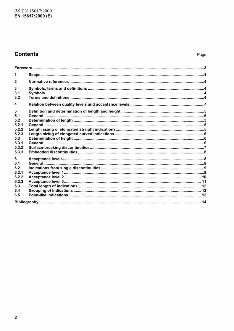
Contents Page
Foreword ..............................................................................................................................................................3
1 Scope ......................................................................................................................................................4
2 Normative references ............................................................................................................................4
3 Symbols, terms and definitions ...........................................................................................................43.1 Symbols ..................................................................................................................................................43.2 Terms and definitions ...........................................................................................................................4
4 Relation between quality levels and acceptance levels ....................................................................4
5 Definition and determination of length and height ............................................................................55.1 General ....................................................................................................................................................55.2 Determination of length ........................................................................................................................55.2.1 General ....................................................................................................................................................55.2.2 Length sizing of elongated straight indications .................................................................................55.2.3 Length sizing of elongated curved indications ..................................................................................65.3 Determination of height ........................................................................................................................65.3.1 General ....................................................................................................................................................65.3.2 Surface-breaking discontinuities .........................................................................................................75.3.3 Embedded discontinuities ....................................................................................................................8
6 Acceptance levels ..................................................................................................................................86.1 General ....................................................................................................................................................86.2 Indications from single discontinuities ...............................................................................................96.2.1 Acceptance level 1 .................................................................................................................................96.2.2 Acceptance level 2 .............................................................................................................................. 106.2.3 Acceptance level 3 .............................................................................................................................. 116.3 Total length of indications ................................................................................................................. 126.4 Grouping of indications ..................................................................................................................... 126.5 Point-like indications .......................................................................................................................... 12
Bibliography ..................................................................................................................................................... 14
www.bzfxw.com
BS EN 15617:2009EN 15617:2009 (E)
3
Foreword
This document (EN 15617:2009) has been prepared by Technical Committee CEN/TC 121 “Welding”, the secretariat of which is held by DIN.
This European Standard shall be given the status of a national standard, either by publication of an identical text or by endorsement, at the latest by September 2009, and conflicting national standards shall be withdrawn at the latest by September 2009.
Attention is drawn to the possibility that some of the elements of this document may be the subject of patent rights. CEN [and/or CENELEC] shall not be held responsible for identifying any or all such patent rights.
According to the CEN/CENELEC Internal Regulations, the national standards organizations of the following countries are bound to implement this European Standard: Austria, Belgium, Bulgaria, Cyprus, Czech Republic, Denmark, Estonia, Finland, France, Germany, Greece, Hungary, Iceland, Ireland, Italy, Latvia, Lithuania, Luxembourg, Malta, Netherlands, Norway, Poland, Portugal, Romania, Slovakia, Slovenia, Spain, Sweden, Switzerland and the United Kingdom.
www.bzfxw.com
BS EN 15617:2009EN 15617:2009 (E)
4
1 Scope
This European standard specifies acceptance levels for the time-of-flight diffraction technique (TOFD) of full penetration welds in ferritic steels from 6 mm up to 300 mm thickness which correspond to the quality levels of EN ISO 5817.
These acceptance levels are applicable to indications classified in accordance with CEN/TS 14751.
2 Normative references
The following referenced documents are indispensable for the application of this document. For dated references, only the edition cited applies. For undated references, the latest edition of the referenced document (including any amendments) applies.
CEN/TS 14751, Welding — Use of time-of-flight diffraction technique (TOFD) for examination of welds
EN ISO 5817, Welding — Fusion-welded joints in steel, nickel, titanium and their alloys (beam welding excluded) — Quality levels for imperfections (ISO 5817:2003, corrected version:2005, including Technical Corrigendum 1:2006)
3 Symbols, terms and definitions
3.1 Symbols
h height of an indication (see Figures 1, 2 and 3)
l length of an indication (see Figures 1, 2 and 3)
t nominal wall thickness in accordance with construction drawing or dimension table (see Figures 1, 2 and 3)
3.2 Terms and definitions
For the purposes of this document, the following terms and definitions apply.
3.2.1 embedded discontinuity discontinuity within the volume of the material, separated from the surfaces
3.2.2 surface-breaking discontinuity discontinuity connected to the near (contact) surface or far (reflecting) surface
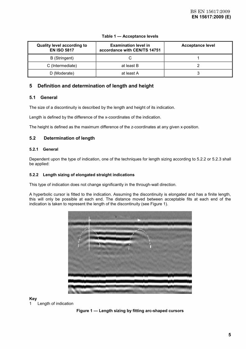
4 Relation between quality levels and acceptance levels
Three different acceptance levels are defined. The relation between these acceptance levels and the quality levels as mentioned in EN ISO 5817 are given in Table 1.
www.bzfxw.com
BS EN 15617:2009EN 15617:2009 (E)
5
Table 1 — Acceptance levels
Quality level according to EN ISO 5817
Examination level in accordance with CEN/TS 14751
Acceptance level
B (Stringent) C 1
C (Intermediate) at least B 2
D (Moderate) at least A 3
5 Definition and determination of length and height
5.1 General
The size of a discontinuity is described by the length and height of its indication.
Length is defined by the difference of the x-coordinates of the indication.
The height is defined as the maximum difference of the z-coordinates at any given x-position.
5.2 Determination of length
5.2.1 General
Dependent upon the type of indication, one of the techniques for length sizing according to 5.2.2 or 5.2.3 shall be applied:
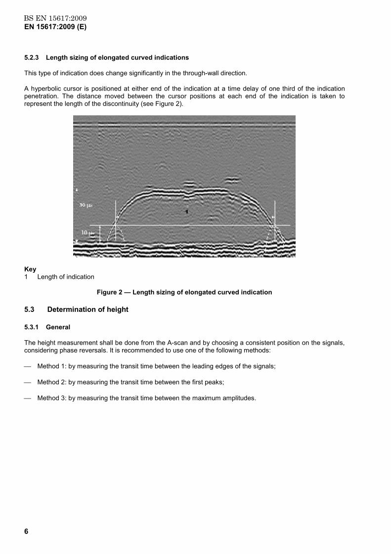
5.2.2 Length sizing of elongated straight indications
This type of indication does not change significantly in the through-wall direction.
A hyperbolic cursor is fitted to the indication. Assuming the discontinuity is elongated and has a finite length, this will only be possible at each end. The distance moved between acceptable fits at each end of the indication is taken to represent the length of the discontinuity (see Figure 1).
Key 1 Length of indication
Figure 1 — Length sizing by fitting arc-shaped cursors
www.bzfxw.com
BS EN 15617:2009EN 15617:2009 (E)
6
5.2.3 Length sizing of elongated curved indications
This type of indication does change significantly in the through-wall direction.
A hyperbolic cursor is positioned at either end of the indication at a time delay of one third of the indication penetration. The distance moved between the cursor positions at each end of the indication is taken to represent the length of the discontinuity (see Figure 2).
Key 1 Length of indication
Figure 2 — Length sizing of elongated curved indication
5.3 Determination of height
5.3.1 General
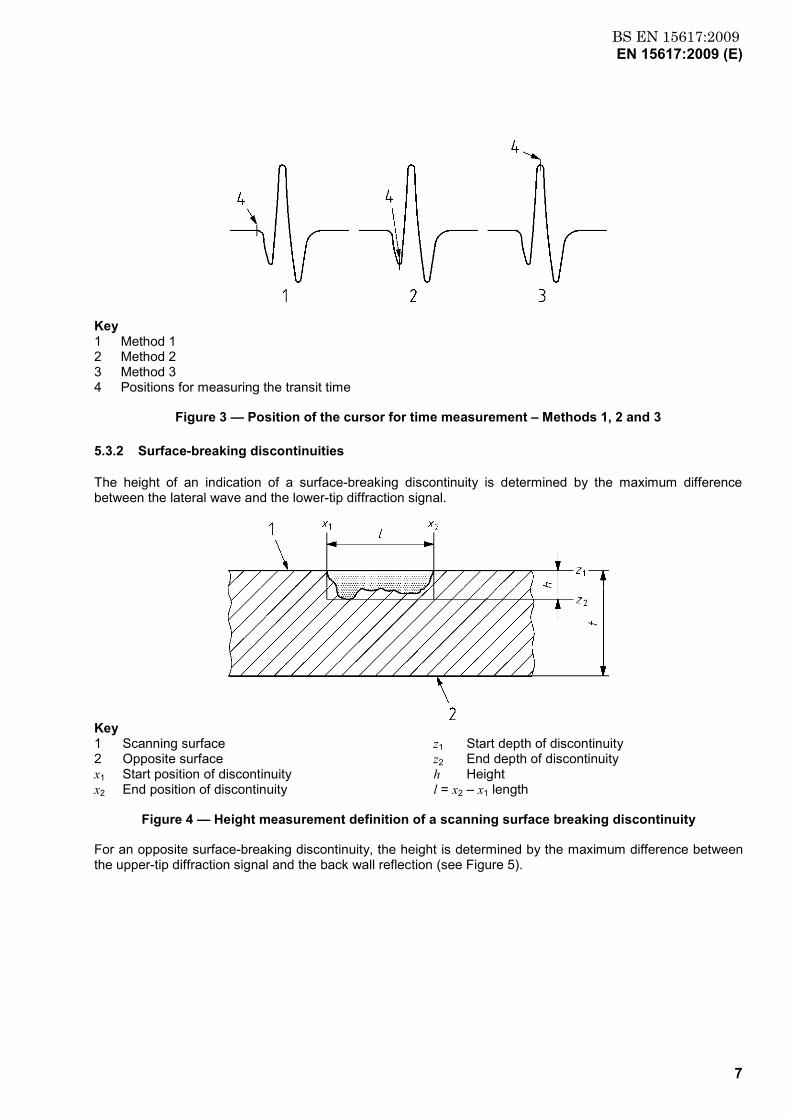
The height measurement shall be done from the A-scan and by choosing a consistent position on the signals, considering phase reversals. It is recommended to use one of the following methods:
Method 1: by measuring the transit time between the leading edges of the signals;
Method 2: by measuring the transit time between the first peaks;
Method 3: by measuring the transit time between the maximum amplitudes.
www.bzfxw.com
BS EN 15617:2009EN 15617:2009 (E)
7
Key 1 Method 1 2 Method 2 3 Method 3 4 Positions for measuring the transit time
Figure 3 — Position of the cursor for time measurement – Methods 1, 2 and 3
5.3.2 Surface-breaking discontinuities
The height of an indication of a surface-breaking discontinuity is determined by the maximum difference between the lateral wave and the lower-tip diffraction signal.
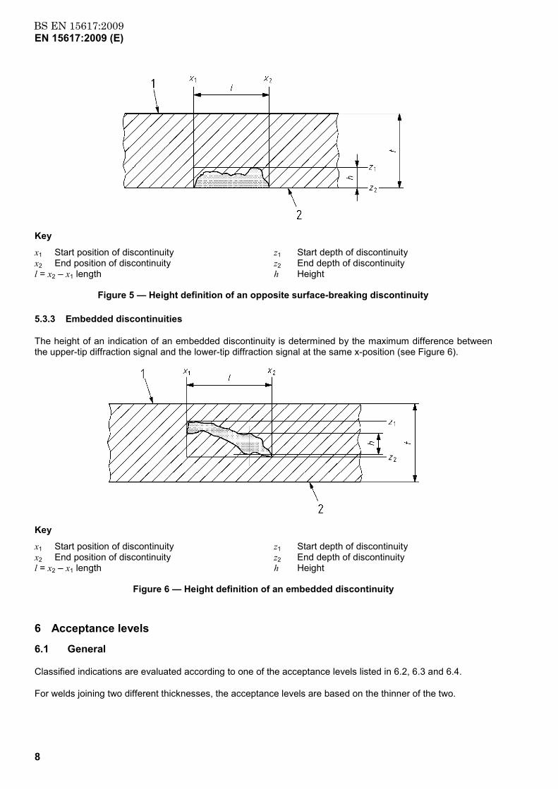
Key 1 Scanning surface z1 Start depth of discontinuity 2 Opposite surface z2 End depth of discontinuity x1 Start position of discontinuity h Height x2 End position of discontinuity l = x2 – x1 length
Figure 4 — Height measurement definition of a scanning surface breaking discontinuity
For an opposite surface-breaking discontinuity, the height is determined by the maximum difference between the upper-tip diffraction signal and the back wall reflection (see Figure 5).
www.bzfxw.com
BS EN 15617:2009EN 15617:2009 (E)
8
Key
x1 Start position of discontinuity z1 Start depth of discontinuity x2 End position of discontinuity z2 End depth of discontinuity l = x2 – x1 length h Height
Figure 5 — Height definition of an opposite surface-breaking discontinuity
5.3.3 Embedded discontinuities
The height of an indication of an embedded discontinuity is determined by the maximum difference between the upper-tip diffraction signal and the lower-tip diffraction signal at the same x-position (see Figure 6).
Key
x1 Start position of discontinuity z1 Start depth of discontinuity x2 End position of discontinuity z2 End depth of discontinuity l = x2 – x1 length h Height
Figure 6 — Height definition of an embedded discontinuity
6 Acceptance levels
6.1 General
Classified indications are evaluated according to one of the acceptance levels listed in 6.2, 6.3 and 6.4.
For welds joining two different thicknesses, the acceptance levels are based on the thinner of the two.
www.bzfxw.com
BS EN 15617:2009EN 15617:2009 (E)
9
For welds subject to dynamic loading or being sensitive to cracking (e.g. longitudinal, transverse), more stringent near-surface acceptance levels or the use of additional NDT techniques may be specified.
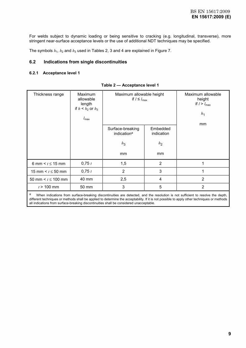
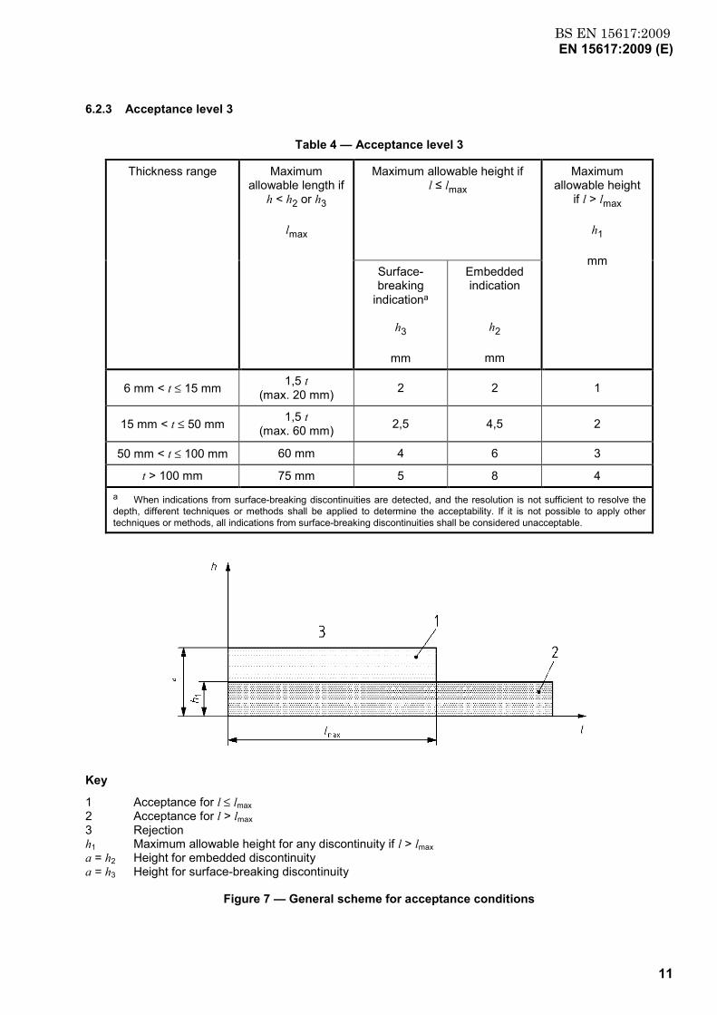
The symbols h1, h2 and h3 used in Tables 2, 3 and 4 are explained in Figure 7.
6.2 Indications from single discontinuities
6.2.1 Acceptance level 1
Table 2 — Acceptance level 1
Thickness range Maximum allowable
length if h < h2 or h3
lmax
Maximum allowable height if l ≤ lmax
Maximum allowable height
if l > lmax
h1
mm
Surface-breaking indicationa
h3
mm
Embedded indication
h2
mm
6 mm < t ≤ 15 mm 0,75 t 1,5 2 1
15 mm < t ≤ 50 mm 0,75 t 2 3 1
50 mm < t ≤ 100 mm 40 mm 2,5 4 2
t > 100 mm 50 mm 3 5 2 a When indications from surface-breaking discontinuities are detected, and the resolution is not sufficient to resolve the depth, different techniques or methods shall be applied to determine the acceptability. If it is not possible to apply other techniques or methods all indications from surface-breaking discontinuities shall be considered unacceptable.
www.bzfxw.com
BS EN 15617:2009EN 15617:2009 (E)
10
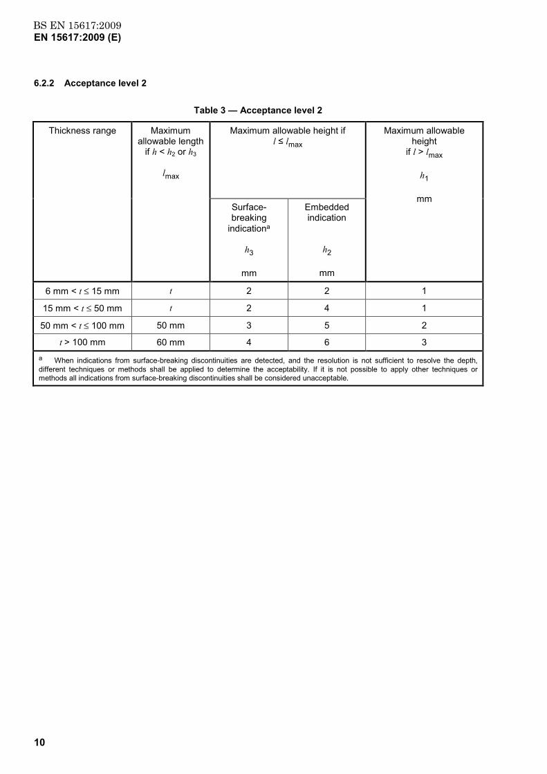
6.2.2 Acceptance level 2
Table 3 — Acceptance level 2
Thickness range Maximum allowable length
if h < h2 or h3
lmax
Maximum allowable height if l ≤ lmax
Maximum allowable height
if l > lmax
h1
mm
Surface-breaking
indicationa
h3
mm
Embedded indication
h2
mm
6 mm < t ≤ 15 mm t 2 2 1
15 mm < t ≤ 50 mm t 2 4 1
50 mm < t ≤ 100 mm 50 mm 3 5 2
t > 100 mm 60 mm 4 6 3 a When indications from surface-breaking discontinuities are detected, and the resolution is not sufficient to resolve the depth, different techniques or methods shall be applied to determine the acceptability. If it is not possible to apply other techniques or methods all indications from surface-breaking discontinuities shall be considered unacceptable.
www.bzfxw.com
BS EN 15617:2009EN 15617:2009 (E)
11
6.2.3 Acceptance level 3
Table 4 — Acceptance level 3
Thickness range Maximum allowable length if
h < h2 or h3
lmax
Maximum allowable height if l ≤ lmax
Maximum allowable height
if l > lmax
h1
mm
Surface-breaking
indicationa
h3
mm
Embedded indication
h2
mm
6 mm < t ≤ 15 mm 1,5 t (max. 20 mm) 2 2 1
15 mm < t ≤ 50 mm 1,5 t (max. 60 mm) 2,5 4,5 2
50 mm < t ≤ 100 mm 60 mm 4 6 3
t > 100 mm 75 mm 5 8 4 a When indications from surface-breaking discontinuities are detected, and the resolution is not sufficient to resolve the depth, different techniques or methods shall be applied to determine the acceptability. If it is not possible to apply other techniques or methods, all indications from surface-breaking discontinuities shall be considered unacceptable.
Key
1 Acceptance for l ≤ lmax 2 Acceptance for l > lmax 3 Rejection h1 Maximum allowable height for any discontinuity if l > lmax a = h2 Height for embedded discontinuity a = h3 Height for surface-breaking discontinuity
Figure 7 — General scheme for acceptance conditions
www.bzfxw.com
BS EN 15617:2009EN 15617:2009 (E)
12
6.3 Total length of indications
The sum of the lengths of the individual indications measured along the weld over a length of 12 t shall be less than or equal to:
• for acceptance level 1: 3,5 t with a maximum of 150 mm,
• for acceptance level 2: 4,0 t with a maximum of 200 mm,
• for acceptance level 3: 4,5 t with a maximum of 250 mm.
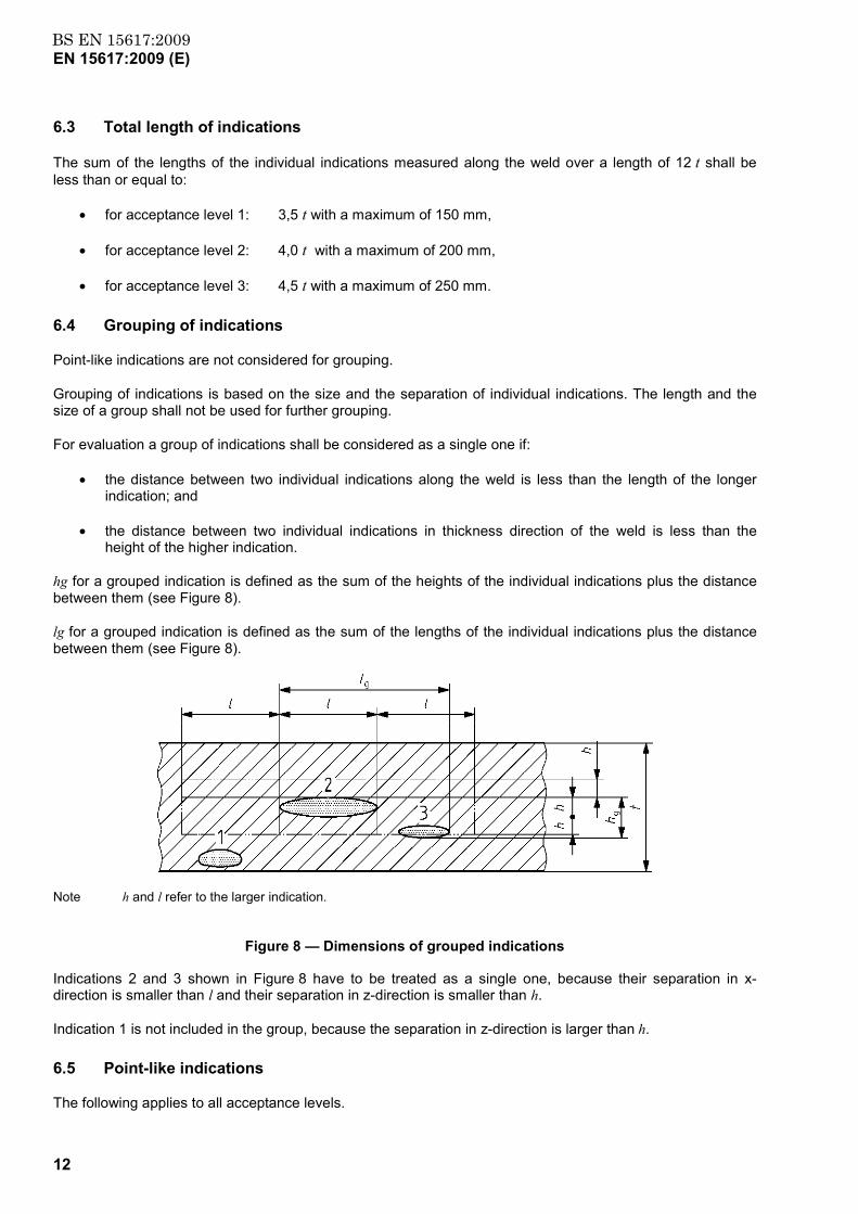
6.4 Grouping of indications
Point-like indications are not considered for grouping.
Grouping of indications is based on the size and the separation of individual indications. The length and the size of a group shall not be used for further grouping.
For evaluation a group of indications shall be considered as a single one if:
• the distance between two individual indications along the weld is less than the length of the longer indication; and
• the distance between two individual indications in thickness direction of the weld is less than the height of the higher indication.
hg for a grouped indication is defined as the sum of the heights of the individual indications plus the distance between them (see Figure 8).
lg for a grouped indication is defined as the sum of the lengths of the individual indications plus the distance between them (see Figure 8).
Note h and l refer to the larger indication.
Figure 8 — Dimensions of grouped indications
Indications 2 and 3 shown in Figure 8 have to be treated as a single one, because their separation in x-direction is smaller than l and their separation in z-direction is smaller than h.
Indication 1 is not included in the group, because the separation in z-direction is larger than h.
6.5 Point-like indications
The following applies to all acceptance levels.
www.bzfxw.com
BS EN 15617:2009EN 15617:2009 (E)
13
The maximum allowable number (N) of single diffraction signals in any 150 mm of weld length can be calculated with:
mm/2,1 tN =
where
N is rounded to the higher integer and
thickness (t) is given in millimetre.
www.bzfxw.com
BS EN 15617:2009EN 15617:2009 (E)
14
Bibliography
[1] EN 12062, Non-destructive examination of welds — General rules for metallic materials

www.bzfxw.com
BS EN 15617:2009
This page has been intentionally left blank
www.bzfxw.com
BS EN15617:2009
BSI GroupHeadquarters 389Chiswick High Road,London, W4 4AL, UKTel +44 (0)20 8996 9001Fax +44 (0)20 8996 7001www.bsigroup.com/standards
BSI - British Standards InstitutionBSI is the independent national body responsible for preparing BritishStandards. It presents the UK view on standards in Europe and at theinternational level. It is incorporated by Royal Charter.
Revisions
British Standards are updated by amendment or revision. Users of BritishStandards should make sure that they possess the latest amendments oreditions.
It is the constant aim of BSI to improve the quality of our products and services.We would be grateful if anyone finding an inaccuracy or ambiguity while usingthis British Standard would inform the Secretary of the technical committeeresponsible, the identity of which can be found on the inside front cover. Tel:+44 (0)20 8996 9000. Fax: +44 (0)20 8996 7400.
BSI offers members an individual updating service called PLUS which ensuresthat subscribers automatically receive the latest editions of standards.
Buying standards
Orders for all BSI, international and foreign standards publications should beaddressed to Customer Services. Tel: +44 (0)20 8996 9001. Fax: +44 (0)20 89967001 Email: [email protected] You may also buy directly using a debit/creditcard from the BSI Shop on the Website http://www.bsigroup.com/shop
In response to orders for international standards, it is BSI policy to supply theBSI implementation of those that have been published as British Standards,unless otherwise requested.
Information on standards
BSI provides a wide range of information on national, European andinternational standards through its Library and its Technical Help to ExportersService. Various BSI electronic information services are also available whichgive details on all its products and services. Contact Information Centre. Tel:+44 (0)20 8996 7111 Fax: +44 (0)20 8996 7048 Email: [email protected]
Subscribing members of BSI are kept up to date with standards developmentsand receive substantial discounts on the purchase price of standards. For detailsof these and other benefits contact Membership Administration. Tel: +44 (0)208996 7002 Fax: +44 (0)20 8996 7001 Email: [email protected]
Information regarding online access to British Standards via British StandardsOnline can be found at http://www.bsigroup.com/BSOL
Further information about BSI is available on the BSI website at http://www.bsigroup.com.
Copyright
Copyright subsists in all BSI publications. BSI also holds the copyright, in theUK, of the publications of the international standardization bodies. Except aspermitted under the Copyright, Designs and Patents Act 1988 no extract maybe reproduced, stored in a retrieval system or transmitted in any form or by anymeans – electronic, photocopying, recording or otherwise – without prior writtenpermission from BSI.
This does not preclude the free use, in the course of implementing the standard,of necessary details such as symbols, and size, type or grade designations. Ifthese details are to be used for any other purpose than implementation then theprior written permission of BSI must be obtained.
Details and advice can be obtained from the Copyright and Licensing Manager.Tel: +44 (0)20 8996 7070 Email: [email protected]