
EN 102.00.BLS V1 - Innovation in Biometrics & Security :: … · · 2015-02-025.3 Usage summary...
44
EN 102.00.BLS V1.13
Transcript of EN 102.00.BLS V1 - Innovation in Biometrics & Security :: … · · 2015-02-025.3 Usage summary...

EN 102.00.BLS V1.13

2
This manual is provided for information purpose only. All information included
herein is subject to change without notice. Suprema is not responsible for any
changes, direct or indirect, arising from or related to us of this manual.
Copyright 2008 Supremainc. All rights reserved.

3
Contents
Safety Instructions .................................................................................................... 4
1. Before Use ............................................................................................................. 5
1.1 Components .................................................................................................................. 5 1.2 Body .............................................................................................................................. 6 1.3 Methods for fingerprint input .......................................................................................... 7 1.4 System setup procedure ................................................................................................ 8
1.4.1 Registering the initial administrator .......................................................................... 9 1.4.2 Stand-alone configuration ...................................................................................... 10 1.4.3 Configuring Secure I/O .......................................................................................... 12 1.4.4 Configuring environment settings .......................................................................... 14
1.5 Authorization methods ................................................................................................. 14
2. User Management ................................................................................................ 16
2.1 Enrolling a user ........................................................................................................... 16 2.2 Editing a user data....................................................................................................... 18 2.3 Deleting a user data .................................................................................................... 21
3. Configuration for Screen and Sound ................................................................. 22
3.1 Date, Time ................................................................................................................... 22 3.2 Backlight...................................................................................................................... 23 3.3 Sound .......................................................................................................................... 23
4. Device Configuration .......................................................................................... 24
4.1 Authorization ............................................................................................................... 24 4.2 In/Out .......................................................................................................................... 26 4.3 System ........................................................................................................................ 30
5. FAQ ..................................................................................................................... 334
5.1 Error messages ......................................................................................................... 345 5.2 Troubleshooting ......................................................................................................... 356 5.3 Usage summary ........................................................................................................ 367 5.4 System Installation .................................................................................................... 378
5.4.1 Cable specifications ............................................................................................. 378 5.4.2 Connecting Power & 485 ..................................................................................... 389 5.4.3 Connecting the relay ............................................................................................. 40 5.4.4 Connecting the switch ......................................................................................... 411 5.4.5 Electrical specifications ....................................................................................... 411 5.4.6 Installing the bracket ........................................................................................... 422
5.5 Specifications ............................................................................................................ 433

4
Safety Instructions
Installation
In Use
Do not arbitrarily install or repair the product.
The warranty does not apply to any product damage caused by an arbitrary installation
or repair.
Endure that password does not
exposed to unauthorized
individuals. Frequent change of
password is recommended.
Any illegal access to
your product may
happen.
Do not operate the product with
wet hands and keep the device
away from any liquid contact. It may cause a damage
or a failure to the
product..
Do not forcibly press the buttons
of the product and avoid any
contact with sharp object to the
device. It may cause a failure.
Do not clean the device with any
form of liquid. Use soft and dry
cloth only.

5
1. Before Use
1.1 Components
Main Body Wall mounting bracket Extended bracket (Option)
Fixing Screws
(2 EA) Knife Blocks
(2 EA)
Star-shape wrench (For fixing bracket)
Adapter (Option)
Shrinkable Tubes
The components shown above may differ depending on the installation
environment.
Diode
(1 EA)

6
1.2 Body
No. Name Description
1 LCD
Display
The operation status is displayed.
2 Key Pad 0–9 Buttons: Used to enter the ID and password.
< > Arrow Buttons: Used to move the selected item.
Button: Used to select the desired function.
Button: Used to enter the menu.
Button: Used to exit from the menu or cancel the desired action.
3 LED Lamp The operation status is displayed with an alert sound.
- Green (Sound: beep beep beep beep!): Authorization success
- Red (Sound: beep beep beep!) : Authorization failure
- Pink (Sound: beep!) : Processing
- Blue and Sky Blue blink in turn at an interval of 2 seconds (No sound): Normal
operation
- Red and Pink blink in turn at an interval of 2 seconds (No sound): Device locked or
no administrator
- Blue and Red blink in turn at an interval of 2 seconds (No sound): The time is reset
due to battery discharge.
- Red blinks at an interval of 2 seconds (No sound): Device initialization failure.
Please contact with the manufacturer.
- Yellow blinks shortly (No sound): Input ready status
4 Fingerprint
Touch Area
Used to input a fingerprint for authentication.

7
1.3 Methods for fingerprint input
BioLite Solo can easily recognize fingerprints even though the angle and location of the
pattern change. However, it is recommended to properly input fingerprints for more
precise recognition.
Selecting a finger on fingerprint enrollment
How to proerply place a fingerprint
Place your finger firmly on the sensor area.
Adjust the finger so that its middle position can be located in the center
of the sensor.
When the finger is vertically placed or its angle goes astray, the
recognition may be a failure.
Up to two fingerprints can be enrolled for each user in preparation of
any abnormal situation like having a wounded finger or carrying an
object with a hand.
In the case of a low recognition, the user can register
the same fingerprint twice to increase the recognition
rate.
It is recommended to use the index or middle finger.
In case of other fingers, the recognition rate
decreases because it tends to be more difficult to
place the finger in the center of the sensor area.
Place the first
Finger
When enrolling your fingerprint, the first finger input window prompts.
Then register the desired finger on the terminal as shown in the figure
below.
When the re-entry window appears with a “tick” sound, re-enter the
previously enrolled finger. The fingerprint input is made twice.
(Gently push your finger on the sensor to have a full fingerprint.)

8
1.4 System setup procedure
Install the system according to the environment
- Grasp the locations for installation site, door open switch,
dead bolt, and such.
- Install the system (see 5.4).
Step 1
Register an initial administrator - Register the initial administrator for setting devices (See 1.4.1). Step 2
Configure the system - Stand alone configuration (see 1.4.2.) or
- Secure I/O configuration (see 1.4.3) Step 3
Test for system operation - Check the door lock/unlock status and switch operation. - Deliver the setting items to the customer.
Step 4
Configure the environment - Configure various environments (see 1.4.4). Step 5
Register users - Use the system after user registration (see 2.1). Step 6

9
1.4.1 Registering the initial administrator
There is no administrator set for the product in the initial status. So register an
administrator for configuring the environments for relay, door open switch, door open
detection sensor, and such.
1. When the product is connected, a window
appears as shown in the right figure. Enter an ID
and press OK.
2. When the authorization mode window appears,
use / buttons to move to PIN Only, and
press OK.
3. When the password entry window appears, enter
the desired password and press OK.
4. When the password re-entry window appears,
enter the previously input password again and
press OK.
5. The completion message window appears.
Operation Mode
PIN Only
Enroll
Enter PIN
****
Enroll
Confirm PIN
****
Enroll
Completed
This procedure is necessary to temporarily configure the installation-
related settings. Modify the administrator information after the
installation is complete.
Enter ID 1
Enroll Admin

10
1.4.2 Stand-alone configuration
This configuration is the most common installation method.
1. As shown in the figure, connect BioLite Solo to
respective switches.
※ See “5.4.6 Installing the bracket.”
2. Configure the internal relay settings as shown below. (It is explained based on the
figure above.)
Use / buttons to
select Internal and
press OK.
Use / buttons to
select Input 0 and press
OK.
Relay Internal
Door
Exit Button Input 0
Internal
Use / buttons to
select N.O and press
OK.
*N.O/N.C
Type N.O
Exit Button
Device In/Out
Use / buttons to
select the In/Out icon and
press OK.
Press MENU -> Enter ID -
> Enter the password ->
Use / buttons to
select the Device icon
and press OK.
Item Door
In/Out
Use / buttons to
select Door and press
OK.
For actual wring method,
see ”5.4 System Installation.”
Cont.

11
※ Opening Mode
- Temporary Open: When the door is open, it is automatically closed after a specific time.
- Toggle: The door is open after the first authorization success and it remains unlocked
until the second authorization success.
Enter the time and press
OK.
*The time is set for
automatically closing the
door after the specified
time.
Use / buttons to
select Not Use for Held
Open Alarm and press OK.
*Not Use/Sound/
Backlight/Sound and
Light/SIO Relay0/SIO
Relay1
Door Sensor
Input 1
Internal
Held Open Alarm
Not Use
Door
Use / buttons to
select N.O and press OK.
*N.O/N.C
Use / buttons to select
Input 1 and press OK.
*Not Use/Input0/Input1
Use / buttons to
select Temporary Open
for opening mode and
press OK.
* Temporary Open/ Toggle
Opening Mode Temporary Open
Door
Type N.O
Door Sensor
Open Time 3
Door
Use / buttons to
select Not Use for Forced
Open Alarm and press OK.
*Not Use/Sound/
Backlight/Sound and
Light/SIO Relay0/ SIO
Relay1
The completion message
window appears.
Forced Open Alarm
Not Use
Door
Complete
When you exit from the menu before completing the relay setup, the
configuration is not stored so please finish configuration until the
message “Complete” appears.

12
Cont.
1.4.3 Configuring Secure I/O
This connects BioLite Solo to Secure I/O.
1. Connect wires between BioLite Solo, Secure I/O, and respective switches as shown
below.
※ See “5.4.6 Installing the bracket.”
2. Configure the relay settings as shown below. (Based on the figure above)
Use / buttons to
select SIO Relay 0 and
press OK.
Use / buttons to select
SIO Relay 0 and press OK. (*Not Use/ SIO Input 0/ SIO
Input 1)
Relay SIO Relay 0
Door
Exit Button SIO Input 0
SIO Relay 0
Use / buttons to
select N.O and press OK.
Type N.O
Exit Button
Device In/Out
Use / buttons to
select the In/Out icon and
press OK.
Press Menu -> Enter ID ->
Enter password ->Use/
buttons to select the
Device icon and press OK.
Item Door
In/Out
Use / buttons to
select Door and press
OK.
For actual wiring, see “5.4 System
Installation.”
Sync button should be pressed after complete the relay setting.
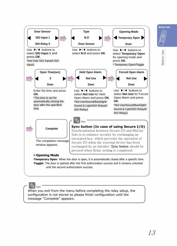
13
※Opening Mode -Temporary Open: When the door is open, it is automatically closed after a specific time.
-Toggle: The door is opened after the first authorization success and it remains unlocked
until the second authorization success.
Enter the time and press
OK.
*The time is set for
automatically closing the
door after the specified
time.
Use / buttons to
select Not Use for Held
Open Alarm and press OK.
*Not Use/Sound/Backlight/
Sound & Light/SIO Relay0/
SIO Relay1
Door Sensor
SIO Input 1
SIO Relay 0
Held Open Alarm
Not Use
Door
Use / buttons to
select N.O and press OK.
Use / buttons to
select SIO Input 1 and press OK.
*Not Use/ SIO Input0/ SIO
Input1
Opening Mode Temporary Open
Door
Use / buttons to
select Temporary Open
for opening mode and
press OK.
* Temporary Open/Toggle
Type N.O
Door Sensor
Open Time(sec)
3
Door
Use / buttons to
select Not Use for Forced
Open Alarm and press
OK.
*Not Use/Sound/Backlight/
Sound & Light/SIO Relay0/
SIO Relay1
The completion message
window appears.
Forced Open Alarm
Not Use
Door
Complete
When you exit from the menu before completing the relay setup, the
configuration is not stored so please finish configuration until the
message “Complete” appears.
Sync button (In case of using Secure I/O)
Synchronization between Secure I/O and BioLite Solo is to enhance security by exchanging an
encrypted key, which prevents the operation of Secure I/O when the external device has been exchanged by an intruder. Sync button should be
pressed when Relay setting is completed.

14
1.4.4 Configuring environment settings
Settings for date and time: Set the values as “3.1 Date, Time.”
Setting for authorization period: Set the value after reading the case of
authorization period selection in “4.1 Authorization,”
Fingerprint authorization related settings: Set the values after reading the case of
fingerprint selection in “4.1 Authorization.”
Setting for fingerprint sensor mode: Set the value after reading the case of
fingerprint sensor mode selection in “4.1 Authorization.”
1.5 Authorization methods
Finger Only
Finger or PIN
Enter the ID of the
user and press OK.
Enter the password
of the user and
press OK.
The door is open with the
authentication success
message.
Input the fingerprint
of the user.
The door is open with the
authentication success
message.
Enter ID
2
Enter Finger or PIN
****
Access Granted
ID : 2
Access Granted
ID : 2
BioLite Solo
10:33:02
In case of the user registration by Finger or PIN, you can open the
door by entering the fingerprint only.
Input the fingerprint
of the user. The door is open with the
authentication success
message.
Access Granted
ID : 2
BioLite Solo
10:33:02
Or

15
Finger and PIN
PIN Only
Enter the ID of the
user and press OK. Input the fingerprint
of the user. Enter the password
of the user and
press OK.
The door is open with the
authentication success
message.
Enter ID
2
Enter Finger Enter PIN
****
Access Granted
ID : 2
Enter ID
2
Enter the ID of the
user and press OK. Enter the password
of the user and
press OK.
The door is open with the
authentication success
message.
Enter PIN
****
Access Granted
ID : 2

16
2. User Management This chapter explains how to enroll, modify, and delete user data.
2.1 Enrolling a user
You can enroll a new user as shown below:
1. Use / buttons to select the User ( ) icon
and press OK.
2. Use / buttons to select Enroll ( ) icon and
press OK.
3. The ID that can be used appears. Use it or enter
another ID and press OK.
(1–8 digit number)
4. Use / buttons to select Level and press OK.
(Level: General /Administrator)
※The user enrollment and environment configuration
are enabled only in Administrator level.
5. Use / buttons to select Operation Mode.
(Finger Only /PIN Only/Finger or PIN/Finger and
PIN)
※ Refer “1.5 Authorization methods.”
User
Enroll
Enter ID
3
Enroll
Level
General
Enroll
Operation Mode
Finger Only
Enroll
ID is used to edit or delete the user data so
please keep it carefully.

17
6. Enter the finger or PIN depending on the operation mode.
(Password: 4–8 digit number, Fingerprint: 1st finger/1st + 2nd fingers)
Finger Only/Finger or PIN/Finger and PIN
※In order to skip the second fingerprint enrollment after enrolling the first
fingerprint, press ESC.
※The user can enroll one or two fingerprints for passing the door.
PIN Only/ Finger and PIN
※For password, it is recommended to enter 4 to 8 digit number not to be easily
exposed.
7. When the user enrollment is successfully done,
the completion message window appears.
※User can be enrolled up to maximum 200.
Completed
Confirm PIN
*****
Enroll
Place the first
finger again
Place the first
finger
Place the second
finger
(Skip=ESC)
Enter PIN
*****
Enroll
Place the first finger
on the sensor. Place the same finger
on the sensor again. Place the second
finger in the same
manner.

18
2.2 Editing a user data
You can modify the data of the previously enrolled user.
1. Use / buttons to select the User ( ) icon
and press OK.
2. Use / buttons to select the Edit ( ) icon
and press OK.
3. Enter the ID or fingerprint of the desired user and
press OK.
4. Use / buttons to select the desired item and press OK.
※ Select any of Level, Operation Mode, Security Level, Fingerprint, PIN, and Access
Timezone.
Changing the user level
※The user registration and environment configuration are enabled only in
Administrator level.
User
Item Level
Edit
Use / buttons
to select Level and
press OK.
Use / buttons
to select General or
Administrator.
Press OK.
Edit
Enter ID/Finger
4
Edit
Level General
Edit

19
Changing the operation mode of the user
※Operation: *PIN Only/Finger or Pin/Finger and PIN/Finger Only
Changing the security level of the user
※ Security Level: *Per Device/Lower/Low/Normal/High/Higher
-Per Device: The security in “Device>Authorization>Fingerprint>” on page 25 is applied.
-The higher the security level, the more sensitive the fingerprint recognition.
But the authorization failure rate can increase.
Changing the fingerprint of the user
Item
Operation Mode
Edit
Use / buttons to
select Operation Mode
and press OK.
Use / buttons
to select a operation
mode and press OK.
Press OK.
Use / buttons to
select Security Level and
press OK.
Use / buttons
to select a security
level.
Place the first
finger again
Operation Mode
Finger Only
Edit
Item
Security Level
Edit
Security Level
Normal
Edit
Press OK.
Item
Fingerprint
Edit
Place the second
finger
(Skip=ESC)
Place the first
finger
Use / buttons to
select Fingerprint and
press OK.
Place the first finger on
the sensor. Place the same finger
on the sensor again.
Enroll the second fingerprint
in the same manner.

20
Changing the PIN of the user
Changing the access timezone (authorization trial is enabled) of the
user
※ Access Timezone: *Per Device /Always Allowed/Always Blocked/Per Weekday
- Per Device: The access timezone set in “4.1 Authorization” is applied.
[In case of selecting Per Weekday]
※Select Weekday: You can select maximum of 5 timezone for each day.
Press OK. Use / buttons to
select Access Timezone
and press OK.
Select the access
time zone of the
user.
Select Weekday
Sunday
Per Weekday
After selecting the timezone for each day
as shown in the figure, enter values for
Start Time and End Time.
Item PIN
Edit
Use / buttons to
select PIN and press OK. Enter the desired
password and press
OK.
After re-entering the
password of the
user, press OK.
Enter PIN ****
Edit
Confirm PIN ****
Edit
Item Access Timezone
Edit
Access Timezone
Per Device
Edit
Timezone 1
Sunday
Start Time(hhmm)
0000
1
End Time(hhmm)
(hhmm) 1200
1
When you exit without setting the time after selecting Select
Weekday only, the start time and end time are set to “00:00” and
Timezone is set to “Always Blocked.”

21
2.3 Deleting a user data
You can delete unnecessary user data.
1. Use / buttons to select the User ( ) icon
and press OK.
2. Use / buttons to select the Delete ( ) icon
and press OK.
3. After entering the ID or finger to delete and press
OK.
4. When the action is successfully made, the
message Deletion appears.
※The deleted user cannot be recovered.
If necessary, enroll it again.
User
Delete
Enter ID/Finger
4
Delete
Deletion
If all the users including the administrator are deleted, you must
register the initial administrator again (see 1.4.1).

22
3. Configuration for Screen and Sound
3.1 Date, Time
You need to set the current system date and time. Based on these settings, the values
are correctly stored when you save data for “Select Weekday” or log data.
1. Use / buttons to select the Screen, Sound
( ) icon and press OK.
2. Use / buttons to select the Date, Time ( )
icon and press OK.
3. Enter the current date by following the suggested
format and press OK.
4. Enter the current time by following the suggested
format and press OK.
Screen, Sound
Date, Time
Date(YYYYMM00)
20080605
Date, Time
Time(hhmmss)
102055
Date, Time

23
3.2 Backlight
1. Use / buttons to select the Screen, Sound
( ) icon and press OK.
2. Use / buttons to select Backlight ( ) icon
and press OK.
3. Use / buttons to select a backlight operation status and press OK.
3.3 Sound
1. Use / buttons to select the Screen, Sound
( ) icon and press OK.
2. Use / buttons to select Sound ( ) icon
and press OK.
3. Use / buttons to select the sound operation status and press OK.
Or
Screen, Sound
Or
Backlight
Mode On at Use
Backlight
Mode Always On
Backlight
Screen, Sound
Sound
Mode On
Sound
Mode Off
Sound

4. Device Configuration
4.1 Authorization
1. Use / buttons to select the Device ( ) icon
and press OK.
2. Use / buttons to select the Authorization
( ) icon and press OK.
3. Use / buttons to select any of Access
Timezone, Fingerprint, and Sensor Mode and
press OK.
In case of Access Timezone
[In case of Per Weekday]
※See the description of [In case of selecting Per Weekday] on page 20.
Item
Access Timezone
Authorization
Press OK. Use / buttons to
select Access Timezone
and press OK.
Select the desired access
time zone. * Always Allowed /Always
Blocked/Per Weekday
Authorization
Item Access Timezone
Authorization
Device
Type Always Allowed
Access Timezone
When you exit without setting the time after selecting Select
Weekday only, the start time and end time are set to “00:00” and
Timezone is set to “Always Blocked.”
The users can use the access time zone specified here. (See the
description in Per Device on page 20.) In order to apply the
setting directly to each user, select one of Always Allowed, Always
Blocked or Per Weekday in user’s access Timezone setting. (refer
page 20)

In case of Fingerprint
※ Security Level: The higher the security level, the more sensitive the fingerprint recognition. But the
authorization failure rate can increase.
※ Image Quality: It is the image quality level used when entering the fingerprint data.
In case of Low, the fingerprint can be easily input but the correct authorization is
not guaranteed.
※ Sensitivity: The higher the value, the more sensitive the sensor.
※ Check Duplicate: When enrolling a user, it determines whether or not to check the fingerprint
data is already enrolled.
Item Fingerprint
Authorization
Use / buttons to
select Fingerprint and
press OK.
Use / buttons to
select Security Level
and press OK.
Use / buttons to select
Security Level and press OK. * Normal /Secure/More Secure
Use / buttons to
select Image Quality and
press OK.
Use / buttons to
select Image Quality and
press OK.
*Normal/High/Low
Use / buttons to
select Sensitivity and
press OK.
Use / buttons to
select Sensitivity level
and press OK.
*0~7
Use / buttons to
select Check Duplicate and press OK.
Use / buttons Check
Duplicate and press OK. * Not Use /Use
Item Security Level
Fingerprint
Security Level Normal
Fingerprint
Item Image Quality
Fingerprint
Image Quality Normal
Fingerprint
Item Sensitivity
Fingerprint
Sensitivity 7
Fingerprint
Item Check Duplicate
Fingerprint
Check Duplicate
Not Use
Fingerprint

In case of Sensor Mode (operates the fingerprint sensor)
※ Sensor Mode: *Always On/ID Entered/OK Pressed
- Always On: The sensor always waits for a fingerprint input.
-ID Entered/OK Pressed: It requires entry of ID or OK before a fingerprint input.
4.2 In/Out
1. Use / buttons to select the Device ( ) icon
and press OK.
2. Use / buttons to select In/Out ( ) icon and
press OK.
3. Use / buttons to select any of Serial Conn.,
Tamper On, and Door and press OK.
In case of Serial Conn.
※ Serial Conn. Speed : Not Use/9600/19200/36400/57600/*115200
-It is used only when the log data is retrieved after connecting the PC.
Press OK. Use / buttons to
select Sensor Mode and
press OK.
Use / buttons
to select a sensor
mode.
Item
Sensor Mode
Authorization
Press OK. Use / buttons to
select Serial Conn. And
press OK.
Use / buttons
to select the data
speed.
Item Serial Conn.
In/Out
Device
On Condition
Always On
Sensor Mode
In/Out
Item Serial Conn.
In/Out
Serial Conn. Not Use
In/Out

Cont.
In case of Tamper On
※ Tamper: *Ignore/Locked
-Locked: When the device is forcibly removed, the Device is locked.
(To release the lock, the administrator must perform authorization.)
In case of Door (When using the internal relay)
※Opening Mode: When a specific time elapses after the door is open, the door is
automatically closed.
Item Tamper On
In/Out
Item Door
In/Out
Press OK. Use / buttons to
select Tamper On and
press OK.
Use / buttons
to select a tamper
method.
Use / buttons
to select Door. Use / buttons
to select Internal. Use / buttons to
select Exit Button.
* Not Use/ Input 0/ Input 1
Tamper Ignore
In/Out
Relay Internal
Door
Exit Button Input 0
Internal
Use / buttons to
select the type for Exit
Button.
*N.O/N.C
Type N.O
Exit Button
Door Sensor
Input 1
Internal
Use / buttons to
select a door sensor type.
*N.O/N.C
Use / buttons to
select Door Sensor.
*Not Use/Input
Opening Mode
Temporary Open
Door
Use / buttons to
select a opening mode.
*Temporary Open/ Toggle
Type N.O
Door Sensor
Enter the time and press
OK. Use / buttons to select
the type for Held Open Alarm.
* Not Use /Sound/Backlight/
Sound& Light/SIO Relay0/
SIO Relay1
Held Open Alarm
Not Use
Door
Open Time(sec)
3
Door

Cont.
※ Opening Mode
- Temporary Open: When the door is open, it is automatically closed after a specific time. - Toggle: The door is opened after the first authorization success and it remains unlocked
until the second authorization success.
In case of Door (When using the SIO relay)
Use / buttons to
select the relay type. Use / buttons to
select the exit button. * Not Use/SIO Input0/
SIO Input1
Relay SIO Relay0
Door
Exit Button SIO Input0
SIO Relay0
Item Door
In/Out
Use / buttons to
select Door.
Use / buttons to select
the type of the exit button.
*N.O/N.C
Type N.O
Exit Button
Enter the held open
time by using the
Numeric buttons and
press OK.
Forced Open Alarm
Not Use
Door
Completed
Use / buttons to select the
type for Forced Open Alarm.
*Not Use/Sound/ Backlight/Sound
and Light/SIO Relay0/ SIO Relay1
The completion message
window appears.
When you exit from the menu before completing the relay setup, the
configuration is not stored so please finish configuration until the
message “Complete” appears.
Door Sensor
SIO Input1
SIO Relay0
Use / buttons to
select the door sensor
type.
*N.O/N.C
Use / buttons to
select the door sensor.
*Not Use/ SIO Input1
Type N.O
Door Sensor
Held Open Time(sec)
30
Door

※Opening Mode: When a specific time elapses after the door is open, the door is
automatically closed.
※Opening Mode - Temporary Open: When the door is open, it is automatically closed after a specific time.
- Toggle: The door is opened after the first authorization success and it remains unlocked
until the second authorization success.
Enter the time and press
OK.
Use / buttons to
select the alarm type.
*Not Use/Sound/Backlight/
Sound and Light/SIO
Relay0/SIO Relay1
Held Open Alarm
Sound
Door
Enter the time for Held
Open Alarm by using
the Numeric buttons
and press OK.
Held Open Alarm(sec)
30
Door
Opening Mode
Temporary Open
Door
Use / buttons to
select the type of the
opening mode.
*Temporary Open/ Toggle
Open Time(sec)
3
Door
Use / buttons to select
the type for Forced Open
Alarm.
*Not Use/Sound/
Backlight/Sound and Light/SIO
Relay0/ SIO Relay1
The completion message
window appears.
Forced Open Alarm
Not Use
Door
Complete

4.3 System
1. Use / buttons to select the Device ( ) icon
and press OK.
2. Use / buttons to select the System ( )
icon and press OK.
3. Use / buttons to select any of Information,
Factory Default, Delete All Log, Delete User DB,
and Language and press OK.
In case of Information
Item Log
Information
Use / buttons to
select Log. Use / buttons to
select Not Use.
Device
System
Item Information
System
Filter Not Use
Log
User All
Filter
Use / buttons to
select any of All and
Select ID.
Use / buttons to
select any of All and
Specify Date.
The log filtering result
appears on the screen.
(Use / buttons to
see the previous/next
logs.)
6/18 14:20(3)
Delete OK
6/18 13:46(3)
Enroll OK
The entire logs appear.
(Use / buttons to
see the previous/next
logs.)
6/18 16:21(1) Set Time
6/18 14:20(3)
Delete OK
※ Filter
- Not Use: Displays all.
- Use: Only the specified log is
displayed.(ID/Date/Event Type)
※ When the date is specified, the
logs occurred earlier than the
specified date.
When “Use”
is selected
Event All
Filter
Use / buttons to
select the event type.
*All/Success/Failure/In/Out/
System
Date All
Filter

In case of Information — Continued
In case of Factory Default
※In case of Initialize, the settings are deleted but the log data and user DB are
not deleted.
Item Factory Default
System
Use / buttons to
select Num. Of User. The number of current users
and the number of fingerprints
enrolled appear.
The version of the
firmware appears.
Use / buttons to
select Factory Default
and press OK.
Use / buttons to
determine whether or
not to initialize it.
*Cancel/ Initialize
Item Num. Of User
Information
Item Firmware Ver.
Information
User
Templates 6/800
4/200
Firmware Ver. V0.9_080603
Information
Initialize? Initialize
Factory Default
In case of Initialize,
the message
Initialized appears.
Initialized
Use / buttons to
select Firmware Ver.
The version of the
hardware appears.
Item Hardware Ver.
Information
Hardware Ver. 1024(Rev.C)
Information
Use / buttons to
select Hardware Ver.
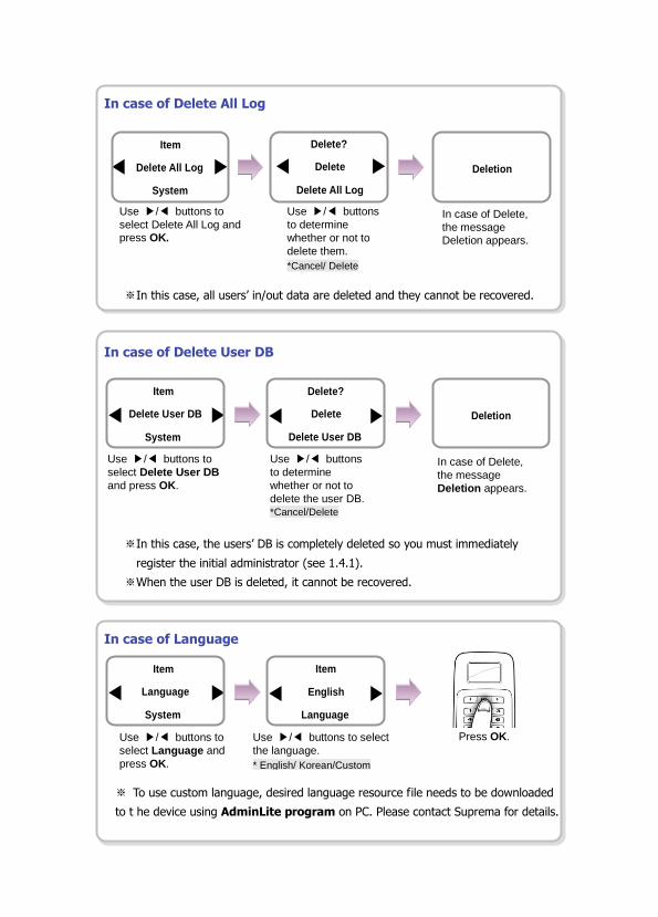
In case of Delete All Log
※In this case, all users’ in/out data are deleted and they cannot be recovered.
In case of Delete User DB
※In this case, the users’ DB is completely deleted so you must immediately
register the initial administrator (see 1.4.1).
※When the user DB is deleted, it cannot be recovered.
In case of Language
※ To use custom language, desired language resource file needs to be downloaded
to t he device using AdminLite program on PC. Please contact Suprema for details.
Item Delete User DB
System
In case of Delete,
the message
Deletion appears.
Use / buttons to
select Delete All Log and
press OK.
Use / buttons
to determine
whether or not to
delete them.
*Cancel/ Delete
In case of Delete,
the message
Deletion appears.
Use / buttons to
select Delete User DB
and press OK.
Use / buttons
to determine
whether or not to
delete the user DB.
*Cancel/Delete
Use / buttons to
select Language and
press OK.
Use / buttons to select
the language.
* English/ Korean/Custom
Press OK.
Item Delete All Log
System
Delete? Delete
Delete All Log
Deletion
Completed
Delete? Delete
Delete User DB
Deletion
Completed
Item Language
System
Item English
Language

In case of Contrast
※ Contrast value is not affected by Factory default.
Use / buttons to
select Contrast and
press OK.
Use / buttons to
adjust contrast parameter.
* Default value is 18
Press OK.
Item Contrast
System
Item 18
System

5. FAQ
5.1 Error messages
Error Message Solution
!Unknown ID The user ID that does not exist in the device is entered.
!Not Matched The entered fingerprint or password is not matched to the enrolled one.
!Duplicate Finger When enrolling a user fingerprint, the fingerprint that has been input
already exists in the device (when checking the duplicated case).
!Failed The number of users exceeds 200, so you cannot enroll more users.
!Not Administrator A normal user tries to enter the menu.
!Not Authorized The fingerprint authentication for the administrator fails when entering
the menu.
!Wrong PIN The entered password for authentication is not matched the enrolled
one.
!ID In Use The user ID to enroll already exists.
!Invalid Value An invalid value is entered.
!Failed The user ID to delete does not exist.
!Unknown Finger The entered fingerprint for entering the menu or editing/deleting a user
data does not exist.
!Access Restricted The authentication trial happens except for the allowed time zone.
!No Log There is no log data.
!Not Recognizable The fingerprint data cannot be extracted due to wrong finger input.
!Device Locked The device is locked because the case has been open.

5.2 Troubleshooting
Category Trouble Solution
Power
The power is supplied but the device does not operate.
- When the device is disconnected from the bracket, it may not work when using the tamper switch.
- Check the adapter or power cable.
Password
The password is lost.
- Enter the queried password after contacting the administrator in case of a normal user.
- When the administrator password is lost, contact with the installation agency.
The locked door is not open after entering the password and pressing OK.
- Check whether the correct password is input. - Check whether you have changed the password
recently. - If you cannot find the password, contact the
administrator.
Fingerprint
The fingerprint has been enrolled but its recognition encounters an error.
- BioLite Solo has the technology of Suprema that won the first award in FVC2004 and FVC2006 because it has world number one quality in recognition.
- For better performance in fingerprint recognition, correct registration is a must.
- Enroll the fingerprint again after seeing “1.3 Methods for fingerprint input”
- The recognition rate may vary due to the characteristic of each finger so enroll the fingerprint of another finger.
It was good at recognizing fingerprints but suddenly it fails in recognition.
- Check whether the finger or the sensor is covered with sweat, moisture, or dust.
- In case the fingerprint has any damage, the device may consider it as the one of wrong person.
- Wipe the finger or sensor with a dry cloth and retry. - When the fingerprint is so dry, blow your steam of
breath into it and retry.
Door lock
Even if you close the door, the door is not locked.
- The electric lock failure is most likely to happen. Check it after contacting the installation agency.
Time The time is not correct.
- BioLite Solo has an embedded battery but it can be discharged by a long time use. Accordingly the time may not be correct. Correct the time after seeing “3.1 Date, Time.”
Administrator
connection
The administrator mode cannot be entered because of losing the administrator password or resignation.
- BioLite Solo allows the administrator to give access rights so only the administrator can enter the menu.
- When you have no choice but to enter the administrator menu, you can be granted an administrator password after following the predefined procedure. (Contact with the installation agency.)

5.3 Usage summary
※ It provides the mainly used functions.
※ button: Used to select the desired function.
Function Method for setting
(Sequentially perform the following items.)
Initial administrator
registration
Enter ID Select PIN Only for authorization method Enter
password Enter password again
Date & time setting Select Screen, Sound ( ) icon Select Date, Time ( ) icon
Enter date Enter time
User registration
Select User ( ) icon Select Enroll ( ) icon Enter ID
Select General or Administrator in Level Select authorization
method Enter fingerprint or password
User password
modification
Select User ( ) icon Select Edit ( ) icon Enter ID or
fingerprint Select PIN Enter the desired password Enter it
again
User fingerprint
modification
Select User ( ) icon Select Edit ( ) icon Enter ID or
fingerprint Select Fingerprint Enter the fingerprint of the user
Enter it again
User authorization
method modification
Select User ( ) icon Select Enroll ( ) icon Enter ID or
fingerprint Select Operation Mode Select an authorization
method
User deletion Select User ( ) icon Select Delete ( ) icon Enter ID or
fingerprint to delete
All user deletion Select Device ( ) icon Select System ( ) icon Select
Delete User DB Select Delete
Initialization
(Environment settings
deletion)
Select Device ( ) icon Select System ( ) icon Select
Factory Default Select Initialize

5.4 System Installation
5.4.1 Cable specifications
Type No. Name Color
Door open
switch
&
Door open
sensor
1 GND Black
2 SWIN 1 Brown
3 GND Black
4 SWIN 0 Purple
Relay
5 Normal Close Orange (White String)
6 Common Green (White String)
7 Normal Open Gray (White String)
Power & 485
8 Power + (12Vdc) Red
9 Power GND Black
10 485 GND White (Black String)
11 485 + Blue (Black String)
12 485 - Yellow (Black String)

5.4.2 Connecting Power & 485
※ RS-485 is used when connecting the Secure I/O.
For power supply, use a product of DC 12V (± 10%) and minimum 500mA.
(To share the power with other devices, use a power supply with higher current ratings.).

5.4.3 Connecting the relay
1. Fail safe lock
2. Fail secure lock
N.O. (Normally Open): A control signal closes the circuit.
N.C. (Normally Closed): A control signal opens the circuit.
Take care of the direction of the diode.
Make sure to install the diode near to the door lock.
Make sure to use different power supplies for the BioLite Solo and the door lock.
Make sure to install the diode at both ends of the circuit as shown in the figures above (and
below) in order to protect the relay contact from the reverse current that occurs when the
door lock works.

3. Automatic door

5.4.4 Connecting the switch
5.4.5 Electrical specifications
Type Name Min. Typ. Max. Notes
Power Voltage (V) 10.8 12 13.2 Use regulated DC power
adaptor only
Current (mA) - 250
Switch
Input
VIH (V) - TBD -
VIL (V) - TBD
Pull-up
resistance (Ω )
- 4.7k - The input ports are
pulled up with 4.7k
resistors
Relay Switching
capacity (A)
- - 1
0.3
30V DC
125V AC
Switching
power
(resistive)
- - 30W
37.5VA
DC
AC
Switching
voltage (V)
- - 110
125
DC
AC

5.4.6 Installing the bracket
1. Fix the bracket to the place where BioLite Solo is
to be installed using the fixing screws.
2. Install BioLite Solo on the bracket.
3. Fix BioLite Solo and the wall mount bracket by
rotating the star-shape screw by the hexagonal
wrench.
If the installation place is on concrete, drill holes, insert
knife blocks into the holes, and fix them by using fixing
screws.

5.5 Specifications
Item Specification
CPU 400MHz DSP
Memory 4MB Flash and 8MB RAM
Fingerprint sensor 500dpi optical sensor
User capacity 200 users (2 fingerprints per user)
Matching speed Less than 1 second
Operation mode Fingerprint, Password, Fingerprint + Password
LCD 128 x 64 Graphic LCD (Monochrome)
Keypad 3x4 keypad, 3 navigation keys
User interface Multi-color LED and Multi-tone buzzer
TTL I/O 2 inputs for exit switch and door sensor
Internal relay Deadbolt, EM lock, door strike, automatic door
IP rate IP65 class
Log capacity 5,000 events
Timer RTC Charge-type Backup Battery Embedded
Rated Voltage DC 12V (Min. 500mA and above)
Size 60 x 185 x 40 mm (Width x Height x Depth)


![BLS Magnet Innovative magnetic materials & solutions · BLS Magnet [8] Attractive technology BLS Magnet [9] Attractive technology BLS Magnet’s magnetic accessories are used in many](https://static.fdocuments.in/doc/165x107/5fe1e8025c38ec6ec573533b/bls-magnet-innovative-magnetic-materials-bls-magnet-8-attractive-technology.jpg)