EMWIN-OQPSK Specifications Final
60
EMWIN OQPSK Transmit and Receiver Prototype Specifications 31-May-05 Prepared for: NOAA/CSC 15245 Shady Grove Road Suite 155 Rockville, MD 20850 Contract No. 50-SANE-6-00028 Prepared by: Avtec Systems, Inc. 14432 Albemarle Point Place Chantilly, VA TR-05-004 Export Controls: Avtec’s products and technology are controlled for export purposes by the U.S. Government pursuant to the Arms Export Control Act and the International Traffic in Arms Regulations or the Export Administration Act and the Export Administration Regulations. It is the end users responsibility to comply with the applicable export laws and regulations before engaging in export activities, including engaging in exports, re-exports, or the disclosure of technical data in the U.S. to foreign persons, a deemed export
-
Upload
mohammed-moufti -
Category
Documents
-
view
91 -
download
1
Transcript of EMWIN-OQPSK Specifications Final

EMWIN OQPSK Transmit andReceiver Prototype Specifications
31-May-05
Prepared for:NOAA/CSC
15245 Shady Grove RoadSuite 155
Rockville, MD 20850
Contract No. 50-SANE-6-00028
Prepared by:Avtec Systems, Inc.
14432 Albemarle Point PlaceChantilly, VA
TR-05-004
Export Controls: Avtec’s products and technology are controlled for export purposes by the U.S. Government pursuant to the Arms Export Control Act and the International Traffic in Arms Regulations or the Export Administration Act and the Export Administration Regulations. It is the end users responsibility to comply with the applicable export laws and regulations before engaging in export activities, including engaging in exports, re-exports, or the disclosure of technical data in the U.S. to foreign persons, a deemed export

TR-05-004 EMWIN OQPSK Transmit and Receiver Prototype Specifications
TABLE OF CONTENTS
TABLE OF FIGURES.....................................................................................................................................ii
INDEX OF TABLES......................................................................................................................................ii
1 INTRODUCTION...................................................................................................................................1
1.1 DOCUMENT SCOPE............................................................................................................................1
1.2 REFERENCES.....................................................................................................................................1
1.3 EMWIN-OQPSK OVERVIEW...........................................................................................................1
2 EMWIN CCSDS DATA FORMAT.......................................................................................................2
2.1 EMWIN-OQPSK VCDU HEADER...................................................................................................3
2.2 EMWIN-OQPSK BIT-STREAM PROTOCOL DATA UNIT (BPDU)....................................................4
2.3 EMWIN-OQPSK CCSDS DATA FORMAT SUMMARY.....................................................................5
3 CHANNEL SPECIFICATION..............................................................................................................6
3.1.1 The channel specification consists of the following..............................................................6
3.2 MODULATOR.....................................................................................................................................7
3.3 OUTPUT CHARACTERISTICS...............................................................................................................8
3.4 OUTPUT SPECTRUM...........................................................................................................................9
3.5 FEC CONVOLUTIONAL ENCODER.....................................................................................................9
3.6 DATA RANDOMIZATION....................................................................................................................9
3.7 REED-SOLOMON ENCODER AND CCSDS BITSTREAM....................................................................10
3.8 LINK ANALYSIS...............................................................................................................................11
4 DEMONSTRATION RECEIVE TERMINAL...................................................................................12
4.1 LIST OF REQUIRED ITEMS................................................................................................................12
4.2 ANTENNA AND LNB.......................................................................................................................13
4.3 IF ADAPTER....................................................................................................................................14
4.4 EMWIN DEMODULATOR AND DECODER SOFTWARE....................................................................17
4.4.1 Installation Procedure.........................................................................................................17
4.4.2 Debug mode and operation.................................................................................................18
4.4.3 Notes on Sound Card Requirements....................................................................................18
4.4.4 EMWIN Data Source...........................................................................................................18
4.4.5 Software Demodulator.........................................................................................................25
4.4.6 Dynamic Link Libraries (developer’s pack)........................................................................40
April 13, 2005 i

TR-05-004 EMWIN OQPSK Transmit and Receiver Prototype Specifications
TABLE OF FIGURES
Figure 1-1 Uplink Processor............................................................................................................................2
Figure 3-1 EMWIN Communications Overview............................................................................................6
Figure 3-2 Theoretical Viterbi RS Performance...............................................................................................7
Figure 3-3 Convolutional Encode Diagram.....................................................................................................9
Figure 3-4 Data Randomization.....................................................................................................................10
Figure 4-1 Receive Terminal Overview........................................................................................................13
Figure 4-2 Software Demodulator Components............................................................................................13
Figure 4-3 IF Adapter Layout........................................................................................................................14
Figure 4-4 IF Adapter Schematic Page 1.......................................................................................................15
Figure 4-5 IF Adapter Schematic Page 2.......................................................................................................16
Figure 4-6 IF Adapter Schematic Page 3.......................................................................................................16
Figure 4-7 Command Syntax Definition.......................................................................................................20
INDEX OF TABLES
Table 2-1 EMWIN-OQPSK Coded VCDU.....................................................................................................3
Table 2-2 VCDU Header Structure..................................................................................................................3
Table 2-3 VCDU Header Definition...............................................................................................................4
Table 2-4 EMWIN-OQPSK BPDU Structure..................................................................................................4
Table 2-5 BPDU Field definitions...................................................................................................................5
Table 2-6 CCSDS Data Format Summary.......................................................................................................5
Table 3-1 OQPSK Output Phase......................................................................................................................8
Table 3-2 CCSDS Link Specification Table..................................................................................................10
Table 3-3 EMWIN Link Budget....................................................................................................................11
April 13, 2005 ii

TR-05-004 EMWIN OQPSK Transmit and Receiver Prototype Specifications
1 INTRODUCTION
1.1 Document Scope
This document provides specifications for the National Oceanic and Atmospheric (NOAA) Emergency Managers Weather Information Network (EMWIN) OQPSK service.
A standard Avtec PTP System provides the transmission component. The PTP System is a Windows server based system that incorporates Avtec-designed software modules and telemetry hardware to provide the required data processing, formatting, and modulation. This document includes an overview of PTP hardware and software architecture, and it provides the specifics of the Avtec software modules that provide the transmission solution. The CCSDS encapsulation of the raw EMWIN bit-stream and the modulation function is performed by the PTP. A reference receiver was built as well to test the end-to-end system performance for the new EMWIN data stream. The general architecture and settings for the receiver are described here as well. The uplink processor architecture is shown in Figure 1-1.
1.2 References
This specification refers to the following documents:[AOS] Advanced Orbiting Systems, Networks and Data Links: Architectural
Specification, Consultative Committee for Space Data Systems, CCSDS 701.0-B-2, November, 1992.
[AOS] can be obtained from http://www.ccsds.org.
[IESS-308e] IntelSat IESS-308e Performance Characteristics for Intermediate Data Rate Digital Carriers using Convolutional Encoding/Viterbi Encoding and QPSK Modulation, Rev. 10.
1.3 EMWIN-OQPSK Overview
EMWIN is a digital direct broadcast service that is being developed to replace the current generation EMWIN transmission signal. The current generation EMWIN is a Frequency Shift Keying (FSK) based broadcast service that currently disseminates the EMWIN data stream. The service is transmitted from the GOES satellite using an L-band down-link frequency at 1690.725 MHz. The next generation EMWIN will be an OQPSK modulation at higher rates and lower power, yet able to be received by most existing front-end hardware as the current generation EMWIN signals. The only know problem with some existing implementations is the stability of the local oscillator. The new frequency for EMWIN will be 1692.7MHz. This document covers the specification of the new OQPSK formatted data stream.
The existing FSK service, also called the “existing 9.6 service” has a 9600 symbols per second (sps) RF signal rate. Since the 9.6 service includes start and stop bits (equivalent
April 13, 2005 1

TR-05-004 EMWIN OQPSK Transmit and Receiver Prototype Specifications
to RS-232: 8 bits, no parity, 1 start/1 stop), the actual information rate is a maximum of 7680 bits per second (bps).
The EMWIN-OQPSK service follows the Consultative Committee for Space Data Systems (CCSDS) recommendations for link architecture, data encapsulation formats, and forward error correction. The EMWIN-OQPSK service will carry the equivalent of twice the existing FSK information rate. The EMWIN-OQPSK information rate is 15360 bps. In order to compensate for the asynchronous relationship between the EMWIN data source and the modulator clock, the information rate is multiplied by 101%. After CCSDS encapsulation and coding is applied, the RF signal rate is 35940 sps. Details on the calculation can be found in sections 3.1.1 and 3.2. Details on the CCSDS formats are discussed in section 2.
Figure 1-1 Uplink Processor
2 EMWIN CCSDS DATA FORMAT
The EMWIN-OQPSK service uses the Consultative Committee for Space Data Systems (CCSDS) Version 2 Transfer Frame format, also referred to as the Advanced Orbiting Systems Virtual Channel Data Unit (AOS VCDU). CCSDS Advanced Orbiting Systems Networks and Data Links 701-0-B.3 [AOS] outlines the recommended architecture for
April 13, 2005 2

TR-05-004 EMWIN OQPSK Transmit and Receiver Prototype Specifications
space to ground links. [AOS] also defines the network layers, services, formats, and grades of service.
EMWIN-OQPSK uses Grade 2 level of service with the entire VCDU protected by Reed-Solomon forward error correction codes. The Coded VCDU is fixed length, 1020 bytes long. EMWIN-OQPSK uses the CCSDS Bit-Stream service.
The Coded VCDU with a 4 byte Attached Sync Marker (ASM) is shown below in Table2-1.
Table 2-1 EMWIN-OQPSK Coded VCDU
ASM0x1ACFFC1D
VCDU Header
BPDU Header
BPDU Data Field Reed-Solomon Check Symbols
¬ 4 octets ® ¬ 6 octets ® ¬ 2 octets ® ¬ 884 octets ® ¬ 128 octets ®¬ 1024 bytes ®
The ASM + Coded VCDU is fixed length, at 1024 bytes. The VCDU header is 6 bytes long. The VCDU header details can be found in 2.1.
EMWIN-OQPSK selected the CCSDS Bit-Stream service for maximum bandwidth efficiency and lowest latency. Selecting the bit-stream service also allows for seamless and transparent migration from the existing FSK broadcast to the OQPSK broadcast. The raw (no start & stop bits) EMWIN bit-stream is inserted into the Bit-Stream Protocol Data Unit (BPDU) bit-stream data field. BPDU details can be found in section 2.2
2.1 EMWIN-OQPSK VCDU Header
The VCDU header of version 2 transfer frames is 6 bytes long. The structure is shown below, in Table 2-2.
Table 2-2 VCDU Header Structure
Version VCDU-ID VCDU Signaling Field
Number SCID VCID Counter Replay Flag Spare
¬2 bits® ¬8 bits® ¬ 6 bits ® ¬ 24 bits ® ¬1 bit® ¬7 bits®
The SCID corresponds to the assigned value of the broadcasting satellite. GOES - ### / GOES-East is currently assigned SCID = TBD. CCSDS version 2 has 63 valid (data content) VCID channels. These are VCID 0 to 62. VCID 63 is used for fill VCDUs (VCDUs containing only fill data). The current EMWIN-OQPSK implementation uses
April 13, 2005 3

TR-05-004 EMWIN OQPSK Transmit and Receiver Prototype Specifications
only one VCID for the EMWIN bit-stream insertion. The EMWIN-OQPSK transport maintains the prioritization embedded within the EMWIN bit-stream. Future use allows multiple VCIDs of varying priorities. The receiver processes and properly de-multiplexes all CCSDS VCIDs, from 0 through 63, for future growth and channel prioritization. The VCID is configurable by NOAA and has been set to 15. Specific VCDU header values are listed in Table 2-3.
Table 2-3 VCDU Header Definition
version number Binary ‘01’ specifying version-2 CCSDS
S/C-ID TBD
VCID Binary ‘001111’ specifying channel 15
VCDU counter sequential count (modulo 16777216) of VCDUs on each virtual channel
signaling field/replay flag
Binary ‘00000000’, specifying real-time VCDUs
2.2 EMWIN-OQPSK Bit-Stream Protocol Data Unit (BPDU)
The bit-stream data field holds a maximum of 884 bytes or 7072 bits. Fill bits are inserted to maintain a constant BPDU data field length of 1024 bytes. VCDUs are synchronously clocked into the EMWIN-OQPSK modulator at a fixed rate. When the Uplink PTP is ready for a VCDU, but there is not enough EMWIN data, fill bits can also be inserted to make a new VCDU available. If there are no EMWIN data bits pending, complete Fill VCDUs (VCID=63) can also be inserted into the modulated stream.
Table 2-4 EMWIN-OQPSK BPDU Structure
BPDU Header BPDU Data Field
Spare Bit-Stream Data Pointer
EMWIN Bit-Stream Data Fill Bits
¬2 bits® ¬ 14 bits ® ¬ 0…7072 bits ® ¬ 7072…0 bits ®
The BPDU has 2 components: the header, and the data field. The first 2 bits of the header are ‘00’. The next 14 bits are the bit-stream data pointer. This points to the last valid data bit in the field. Counting from 1 (first bit), and incrementing for each successive bit, the formula is:
April 13, 2005 4

TR-05-004 EMWIN OQPSK Transmit and Receiver Prototype Specifications
Bit-Stream Data Pointer = {(number of bits) – 1}
In addition, a value of all binary ones signifies that all bits in the field are valid (no fill bits). A value of 7071 (binary ’01 1011 1001 1111) and 16383 (binary ’11 1111 1111 1111) therefore have the same meaning.To optimize processing performance, EMWIN-OQPSK uses Fill VCDUs (VCDUs with VCID=63) rather than 0 length BPDUs (pointer value = binary ’11 1111 1111 1110’) when there is no valid data. Details of BPDU field values are summarized in Table 2-5.
Table 2-5 BPDU Field definitions
Spare Binary ‘00’ Bit-Stream Data Pointer
B Points to the last valid data bit in the Bit-Stream Data fieldB= {(# of the bit) – 1}
EMWIN Bit-Stream Data
EMWIN bit-stream data, no start/stop bits
Fill Bits Fill bits are added to the BPDU data field, for a constant BPDU Data Field of 7072 bits (884 Octets)
2.3 EMWIN-OQPSK CCSDS Data Format Summary
A summary of CCSDS data format specifications is listed in Table 2-6.
Table 2-6 CCSDS Data Format Summary
Component EMWIN CCSDS Format Specification
Coded VCDU 1020 bytes
ASM Hexadecimal ‘1ACFFC1D’
Version Number Binary ‘01’ (version 2)
SCID TBD
VCID 15
Signaling Field 0
BPDU Data Field 0..884 Octets
Reed-Solomon (255,223), interleave 4
Randomization h(x)=x8 + x7 + x5 + x3 +1; initialized to all 1s
Differential Encoding NRZ-M
Convolution (R= 0.5, K=7, NO G2 symbol inversion)
April 13, 2005 5

TR-05-004 EMWIN OQPSK Transmit and Receiver Prototype Specifications
3 CHANNEL SPECIFICATION
3.1.1 The channel specification consists of the following
Modulator
FEC convolutional encoder
Data Randomization
Reed Solomon encoder
The overall process of transmission is as shown in Figure 3-2. First, the serial EMWIN data stream is encapsulated into a version 2 CCSDS (AOS) transfer frame using the Grade-2 bit stream service with attached synchronization marker. At this point in the transmission scheme, the data is referred to as a transfer frame. The Reed Solomon outer code is applied followed by data randomization. The modulator accepts the given data stream, applies NRZ-M encoding, followed by rate ½ convolutional coding which finally gets modulated using OQPSK modulation. The NRZ-M and convolutional codes are implemented by the EF Data CDM-550 modem.
Reed-SolomonEncoder and
Interleaver
Reed-SolomonEncoder and
Interleaver RandomizerRandomizer
DerandomizerDerandomizer
ShortConstraint
LengthConvolutional
Encoder
ShortConstraint
LengthConvolutional
Encoder
ModulatorandRF
ModulatorandRF
Reed-SolomonDecoder and
“De-Interleaver”
Reed-SolomonDecoder and
“De-Interleaver”Viterbi
Decoder
ViterbiDecoder
DemodulatorandRF
DemodulatorandRF
Outer Code Inner Code
FrameSynchronizer
FrameSynchronizer
TransferFrame
TransferFrame
Reed-SolomonEncoder and
Interleaver
Reed-SolomonEncoder and
Interleaver RandomizerRandomizer
DerandomizerDerandomizer
ShortConstraint
LengthConvolutional
Encoder
ShortConstraint
LengthConvolutional
Encoder
ModulatorandRF
ModulatorandRF
Reed-SolomonDecoder and
“De-Interleaver”
Reed-SolomonDecoder and
“De-Interleaver”Viterbi
Decoder
ViterbiDecoder
DemodulatorandRF
DemodulatorandRF
Outer Code Inner Code
FrameSynchronizer
FrameSynchronizer
TransferFrame
TransferFrame
Figure 3-2 EMWIN Communications Overview
The purpose for encoding the data is to obtain improvements in link margins due to the powerful combination of concatenated Reed-Solomon and convolutional encoding and decoding. The complexity of implementing these encoding schemes is somewhat harder
April 13, 2005 6

TR-05-004 EMWIN OQPSK Transmit and Receiver Prototype Specifications
than non-encoded data transmissions, but the payoffs in performance are readily apparent. The theoretical performance of these codes is given in Figure 3-3. At the planned operating points, the coding gain is nearly 7 dB, which will provide enough margin in the link to support the proposed 19.2 kbps service.
Figure 3-3 Theoretical Viterbi RS Performance
3.2 Modulator
For reference purposes, it is assumed that the modulator accepts two parallel input data streams designated the P and Q channel. The P and Q channel are the outputs from the Forward Error Code (FEC) encoder outputs.
April 13, 2005 7

TR-05-004 EMWIN OQPSK Transmit and Receiver Prototype Specifications
The modulator shall use coherent Offset QPSK modulation as the basic signaling format. The OQPSK modulation rate is determined from the requirement that the data service be equivalent in information performance to a 19.2 kilo-baud service as would be implied by operating a RS-232 serial port in the 19.2 kbps mode with 8-N-1 settings. The derived signaling rate is determined considering the following:
1. To guarantee that the transmission bandwidth is adequate, an artificial multiplier on data rates shall be set at 101% of full capacity.
2. Each byte of data on an RS-232 serial port has a start and stop bit. The new EMWIN-OQPSK service will only transmit the information bits, and no start/stop bits.
3. A rate ½ convolutional code shall be used.
4. The Reed-Solomon (255,223) and CCSDS bit stream service overhead specified uses 140 bytes out of 1024 bytes at an interleave depth of 4.
Taking into consideration all of the above factors, the derived coded signaling rate is set at (19200*1.01*8/10) * 2 * (1024/(1024-140)) = 35940 sps.
The Intelsat compatible modulator will be set into an Offset QPSK (OQPSK) modulation format with convolution rate ½ encoding enabled. The symbol rate into the encoder-modulator shall be 17970, which accounts for the rate ½ encoding to be performed within the modulator.
3.3 Output characteristics
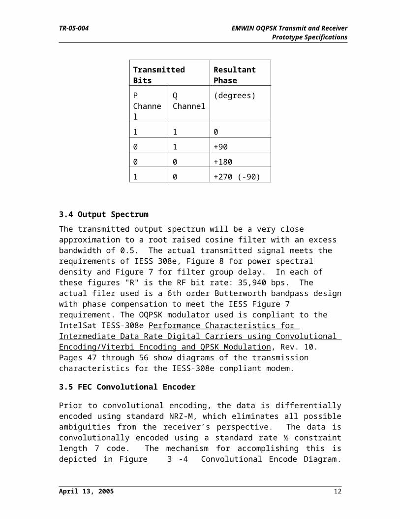
The relationship between the bits to be transmitted and the carrier phase of the modulator output is given in Table 3-7 OQPSK Output Phase. The use of OQPSK results in two possible outcomes from the demodulation process, thus eliminating one pair of ambiguities due to the timing relationship between the P and Q channels. The final ambiguity is eliminated by the use of the NRZ-M encode/decode process, at the cost of slightly higher bit error rates.
Table 3-7 OQPSK Output Phase
Transmitted Bits Resultant Phase
P Channel Q Channel (degrees)
1 1 0
0 1 +90
0 0 +180
1 0 +270 (-90)
April 13, 2005 8

TR-05-004 EMWIN OQPSK Transmit and Receiver Prototype Specifications
3.4 Output Spectrum
The transmitted output spectrum will be a very close approximation to a root raised cosine filter with an excess bandwidth of 0.5. The actual transmitted signal meets the requirements of IESS 308e, Figure 8 for power spectral density and Figure 7 for filter group delay. In each of these figures "R" is the RF bit rate: 35,940 bps. The actual filer used is a 6th order Butterworth bandpass design with phase compensation to meet the IESS Figure 7 requirement. The OQPSK modulator used is compliant to the IntelSat IESS-308e Performance Characteristics for Intermediate Data Rate Digital Carriers using Convolutional Encoding/Viterbi Encoding and QPSK Modulation, Rev. 10. Pages 47 through 56 show diagrams of the transmission characteristics for the IESS-308e compliant modem.
3.5 FEC Convolutional Encoder
Prior to convolutional encoding, the data is differentially encoded using standard NRZ-M, which eliminates all possible ambiguities from the receiver’s perspective. The data is convolutionally encoded using a standard rate ½ constraint length 7 code. The mechanism for accomplishing this is depicted in Figure 3-4 Convolutional EncodeDiagram. The generator polynomials are 133 and 171 Octal. For each input symbol, two output symbols are generated, thus implying a rate ½ code.
Figure 3-4 Convolutional Encode Diagram
3.6 Data Randomization
The data randomization process effectively creates bit transitions within the VCDUs, no matter the actual data contents of the VCDUs. The benefits to the transmission system include better spectrum utilization, as well as easier symbol synchronization, due to the fact that a large number of symbol transitions will always be expected when using the data randomizer. The data randomizer is implemented according to the CCSDS specification, and essentially randomizes all data except for the attached synchronization marker. For each transfer frame, the random generator is reset to an all 1’s state, and is applied modulo 2 to the data within the VCDUs as depicted in Figure 3-5.
April 13, 2005 9

TR-05-004 EMWIN OQPSK Transmit and Receiver Prototype Specifications
+ + +
+
Initialize to an “all ones” state for each Codeblock or Transfer Frame during ASM period
+ = Modulo-2 adder(Exclusive-OR)
= Single Bit Delay
DATA IN(Codeblock or Transfer Frame)
DATA OUT(RandomizedCodeblock or Transfer Frame)
Pseudo-randomsequence
The pseudo-random generator polynomial is: h(x) = x8+x7+x5+x3+1
The first 40 bits of the pseudo=random sequence are:
1111 1111 0100 1000 0000 1110 1100 0000 1001 1010 ...
Figure 3-5 Data Randomization
3.7 Reed-Solomon Encoder and CCSDS Bitstream
The data is Reed Solomon encoded using a standard CCSDS (255,223) code using an interleave depth of 4. An ASM is appended to the VCDU or transfer frames. Frames are to be identified using this ASM. The synchronization marker should be used as the basis for the frame synchronization process. The details of the CCSDS specification are provided in [AOS].
Table 3-8 CCSDS Link Specification Table
Processing Detail EMWIN CCSDS Link Specification
EMWIN Bitstream CCSDS VCDU Bitstream Encapsulation
ASM Hexadecimal ‘1ACFFC1D’
Reed-Solomon (255,223, I=4) not including ASM
CADU 8192 bits default (including ASM & Reed-Solomon; programmable length)
Randomization h(x)=x8 + x7 + x5 + x3 +1; initialized to all 1s
Differential Encoding
NRZ-M
Convolution (R= 0.5, K=7, NO G2 symbol inversion)
Constant Clock Coded rate = 35940 Ksps; Source= Internal Synthesizer or Modem Clock Modem Clock is default
Modulation IESS-308 OQPSK; 74.7 MHz output to Upconverter; 2034.7 MHz
April 13, 2005 10

TR-05-004 EMWIN OQPSK Transmit and Receiver Prototype Specifications
3.8 Link Analysis
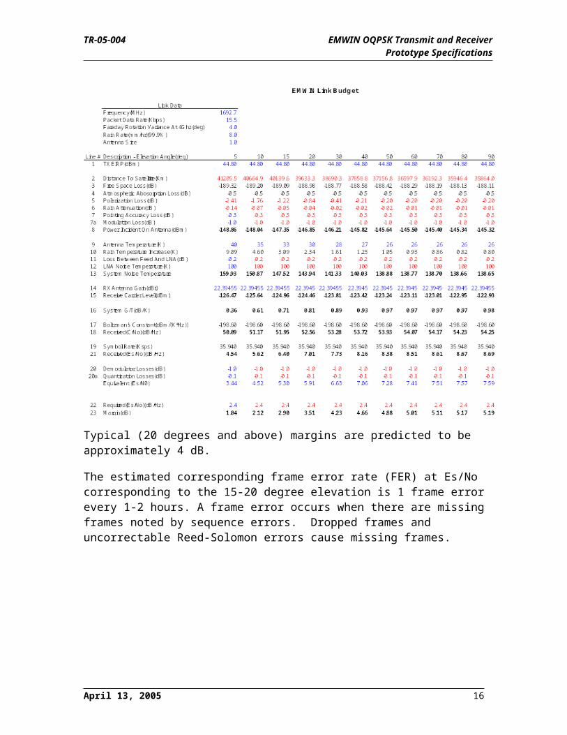
The new link budget for the 19.2 kilo-baud service is given below. Assumptions about the power level and other system losses were made which may need to be revised as new information becomes available. The predicted performance satisfies the worst case need at a 5 degree elevation angle by just over 1 dB. The link budget presented below. This table is an Excel object and can be opened to show calculations.
Table 3-9 EMWIN Link Budget
Typical (20 degrees and above) margins are predicted to be approximately 4 dB.
The estimated corresponding frame error rate (FER) at Es/No corresponding to the 15-20 degree elevation is 1 frame error every 1-2 hours. A frame error occurs when there are missing frames noted by sequence errors. Dropped frames and uncorrectable Reed-Solomon errors cause missing frames.
April 13, 2005 11

TR-05-004 EMWIN OQPSK Transmit and Receiver Prototype Specifications
4 DEMONSTRATION RECEIVE TERMINAL
As part of this effort, Avtec was tasked to provide a demonstration system capable of receiving both the current generation EMWIN signal (EMWIN-I) and the next generation EMWIN signal known as EMWIN-N. The purpose of the receive terminal is to provide for proof of concept, and initial link testing. Additionally, the demonstration system is useful to demonstrate the performance capabilities of the end to end system. Avtec proposed a software demodulator solution, since the performance of the software demodulator can be made to operate near theoretical limits. The partitioning of the receive terminal is shown in Figure 4-6. The majority of the receiver functionality is contained within software, however an IF adapter which converts the signal from the front end down converter to the frequencies and signal levels accepted by a standard sound card is required for the reference implementation.
4.1 List of required items
1. One meter or larger dish antenna, with L-band block down-converter.
2. IF Adapter as described in section IF Adapter4.3.
3. A 350MHz PII or faster with Windows NT,2000, XP, or Server 2003.
a. Sound card capable of simultaneous sampling at 48 KHz stereo.
b. Installed IP stack.
c. Two RS-232 ports (required only if using legacy serial port based display software)
d. > 160 MB memory
4. EMWIN Demodulator Software (as described here)
5. EMWIN Display software.
April 13, 2005 12

TR-05-004 EMWIN OQPSK Transmit and Receiver Prototype Specifications
Consumer PC
A/DConverter
LNBIF Frequency
AdapterIF
SoftwareDemodulator
Software BitSynchronizer
SoftwareViterbi
Decoder
Software Reed-SolomonDecoder
SoftwareFrame
Synchronizer
NOAACompatible File
Formats
Legend
Hardware
Software
ModulatedIF
Serial Port(LegacySupport)
Figure 4-6 Receive Terminal Overview
Figure 4-7 Software Demodulator Components
The goals of the receiver demonstration system were to provide a system capable of processing both EMWIN-I and EMWIN-N signals while utilizing inexpensive readily available hardware. As a whole, we expect the system to operate within 1-2 dB of theoretical including all IF adapter and software receiver losses. The software is distributed as dynamically loadable libraries compiled to run under the various flavors of Windows NT derivatives. Tests have been conducted using Windows NT, 2000, and XP. A quick overview of the software components is shown in Figure 4-7.
4.2 Antenna and LNB
The antenna used for the demonstration system is an Andersen 1.2 M center fed dish. The antenna feed used was a Quorum IFD-1691.0. In addition, we have tested the system with an equivalent Wilmanco integrated feed and LNB. Both of the mentioned LNB’s lowers the carrier frequency of the satellite L-band signal by 1553.5 MHz while providing approximately 60 dB of gain. The outputs are assumed to use 50 ohm cables with N connectors output at the LNB, and an SMA connector at the IF adapter input.
April 13, 2005 13
TR-05-004 EMWIN OQPSK Transmit and Receiver Prototype Specifications
4.3 IF Adapter
The schematic for the IF adapter is given in Figure 4-8 through Figure 4-11. These schematics are high resolution images which can be enlarged for clarity. During the development of the IF adapter, a prototype PCB board was developed as well. The corresponding layout for the prototype board is given in Figure 4-8. The purpose of the IF adapter is to convert the signal obtained from the LNB at approximately 137.225 MHz (current EMWIN frequency) down to 0 Hz, and provide for additional gain and to make the output compatible with a sound card interface. Also contained in the IF adapter is the power source for the L-band down converters which is run as a DC bias voltage of approximately 15 Volts up the antenna line itself. The expected power levels into the IF adapter are around -55 dBm. The acceptable power levels into the front end are between -30 dBm to approximately -70 dBm, with -55 dBm being the design point. The IF adapter supplies approximately 52 dB of gain, and center tunes the 137.225 or 139.200 MHz signal, while providing both I and Q output to the sound card for sampling.
The frequency of the IF adapter is adjusted to the new frequency range by simply changing out the local oscillator for one centered at 139.200 MHz. The prototype simply used a DIP-14 socket to allow easy switch outs of the crystal. One detail of note is that resistors R12 and R13 are not populated. These are shown in the circuit diagram with the do not populate (DNP) notation. This specification documents the as built system. The pads are in place for test options but R12 and R13 are left unpopulated for operations.
Figure 4-8 IF Adapter Layout
April 13, 2005 14

TR-05-004 EMWIN OQPSK Transmit and Receiver Prototype Specifications
Figure 4-9 IF Adapter Schematic Page 1
Figure 4-10 IF Adapter Schematic Page 2
April 13, 2005 15

TR-05-004 EMWIN OQPSK Transmit and Receiver Prototype Specifications
Figure 4-11 IF Adapter Schematic Page 3
Bill of materials for the IF Adapter and low volume approximate costing.
There is an equivalent part from Mini-circuits which can replace the Synergy Microwave mixer (requires slight adjustment to schematic and board), which reduces costs by
April 13, 2005 16

TR-05-004 EMWIN OQPSK Transmit and Receiver Prototype Specifications
$81.00. Replacing the SAWTEK filter can also save about $20.00, which brings the total parts cost down to less than $250.00. This was the target price for the upgrade costs at the beginning of this effort.
4.4 EMWIN Demodulator and Decoder Software
The EMWIN Demodulator and Decoder Software consist of the components as shown in Figure 4-7. As a general rule every attempt has been made to make the software functionally modular, which allows different options to exist for potential implementation solutions. Normally, one would run the given software as a service, which is automatically started at boot up.
4.4.1 Installation Procedure
The minimum system configuration tested is a Pentium II 350 MHz with 160 MB of memory running Window NT 4.0. It is noted that the average CPU utilization for this low end system was observed to average 33%. Operating systems which have been tested include Windows NT, Windows 2000, and Windows XP, and Windows Server 2003. The software can be run as a console application, which may allow the software to run under Windows 95, 98 and ME, but this has not been verified. The demodulation software is distributed as an install shield application. The installation of the software requires administrator privileges for installation to be successful.
1. Verify that the computer you are installing the software onto has the required minimum components.
2. Connect up IF adapter to the line input on the sound card.
3. Verify that the EMWIN signal is seen by the sound card. Use a sound recorder application for this purpose. Audacity, which is freeware is very useful for this purpose.
4. Turn off windows sound effects (Control Panel\Sounds and Multimedia\Scheme) set to none.
5. Run the provided installation program, which installs two services.
6. Reboot the machine.
If all is working as it should, data should start appearing on serial port 1 and/or on TCP port 18000. The receiver is defaulted to receive EMWIN-I, or the current EMWIN data stream. To convert to receiver software configuration to the new OQPSK format, follow steps 7-9. If not, skip ahead to step 11.
7. Open up the EMWIN control panel applet.
8. Select the Demodulator Service panel
April 13, 2005 17
TR-05-004 EMWIN OQPSK Transmit and Receiver Prototype Specifications
9. Change the Signal Format from 0 to 1. Press the Apply button.
10. Stop and then restart the service by selecting the appropriate buttons. After about 30 seconds, the receiver should be locked on to the signal if it is being presented to it correctly.
4.4.2 Debug mode and operation
Both the data source service and the demodulator service can be started in debug or console mode. In order to run the provided software in a debug mode, the service mode must be stopped. The installation package contains three batch files which may be used to execute the necessary steps to run each of the software modules in debug or console mode. These modes are accessed by command line arguments for each of the provided executables. The recognized command line values for the supplied executables are:
install – Installs the application as a service and starts it
remove –Stops the service (application) and removes the service entries from the registry.
debug – Runs the given service as a console application
4.4.3 Notes on Sound Card Requirements
The provided solution will work on most all of the available sound cards; however, there are technical requirements which make the use of some sound card not recommended. In general, a sound card should be able to support sampling at 48 KHz, which is satisfied with all modern day sound cards. If one wishes to use a sound card which is only capable of sampling at 44.1 KHz, then all of the places in the control panel which have the sample rate field need to be changed to 44100, instead of the default 48000. (On Windows 2000, and Windows XP, the actual sample rate is transparent to the application, and leaving it at 48000 is the preferred method). We performed testing on at least five different models and brands of sound cards and came across only one that was deemed to be not acceptable (the Sound Blaster AWE64 model). Apparently this particular model has inter-channel phase distortion which the software is unable to correct. Other Sound Blaster sound card models were tested successfully.
4.4.4 EMWIN Data Source
The Data Source component is responsible for collecting and formatting the digitized data from the A/D hardware. The data source uses a TCP socket connection to send the collected raw samples to the rest of the processing chain. The provided data source acts as a TCP server, and listens for client connections to supply data to the demodulator or whatever other application may need the raw A/D data.
There are essentially three different functions, which are performed through the socket connection to the data source, namely control, status, and data. For Avtec’s delivery, we will be supplying the data source module control as part of the deliverable, but will only
April 13, 2005 18

TR-05-004 EMWIN OQPSK Transmit and Receiver Prototype Specifications
support a sound card device. Normally, the data source module will be run as a service in the background, and its functionality will be controlled through a control panel application. Since the Data Source module will act as a service, it is developed with Windows NT, 2000, or XP in mind. Snapshot below shows the EMWIN Configuration window with default / typical settings.
4.4.4.1.1 Input Device
Determines the sound card device to use as input. Value will default to the first device listed by the OS.
4.4.4.1.2 Input Gain
Set equal to 1. Currently unused in implemented driver.
4.4.4.1.3 Sample Rate
Determines how fast to sample the input data. For normal operations, this needs to be set to 48 KHz, or 44.1KHz. This value sets the default value is the consumer of the data source does not specify another value.
4.4.4.1.4 Sample Size
Determines the sample size in bits. It is assumed that 16 bit sampling will be normally used. This value sets the default value is the consumer of the data source does not specify another value.
April 13, 2005 19

TR-05-004 EMWIN OQPSK Transmit and Receiver Prototype Specifications
4.4.4.1.5 Channel Count
For I and Q sampling, this needs to be set to 2. If one is doing a single channel solution, then changing this value to 1 is required. This value sets the default value is the consumer of the data source does not specify another value.
4.4.4.1.6 Buffer Size
The buffer size that will be used for the sound card input. Larger sizes will lower the CPU utilization and response requirements, while increasing the latency of the signal through the receiver chain.
4.4.4.1.7 TCP Port Number
The outgoing TCP port number used to provide the data source to the demodulator service. Normally this value should be left alone unless a conflict occurs with other installed software.
4.4.4.2 Control Interface (developer information)
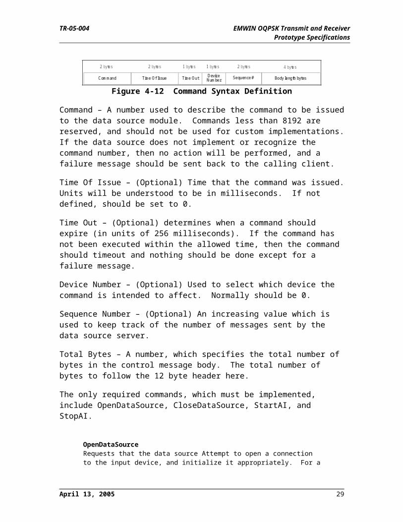
The control interface for the Data Source is defined to be requests sent by the client software, normally the Demodulator. After establishing a TCP connection with the data source module, the client makes requests to the data source using command structures. The header of all command messages will be a total of twelve bytes, which is defined in Figure 4-12. All two byte fields are assumed to be little Endean format. All commands sent will be acknowledged by the server by sending back the same structure as in Figure 4-12. For successful implementation, the body length returned will be 0. If an error or other status information is returned, then the body length will typically be 2 bytes, and the body will contain the status code.
Figure 4-12 Command Syntax Definition
Command – A number used to describe the command to be issued to the data source module. Commands less than 8192 are reserved, and should not be used for custom implementations. If the data source does not implement or recognize the command number, then no action will be performed, and a failure message should be sent back to the calling client.
Time Of Issue – (Optional) Time that the command was issued. Units will be understood to be in milliseconds. If not defined, should be set to 0.
April 13, 2005 20

TR-05-004 EMWIN OQPSK Transmit and Receiver Prototype Specifications
Time Out – (Optional) determines when a command should expire (in units of 256 milliseconds). If the command has not been executed within the allowed time, then the command should timeout and nothing should be done except for a failure message.
Device Number – (Optional) Used to select which device the command is intended to affect. Normally should be 0.
Sequence Number – (Optional) An increasing value which is used to keep track of the number of messages sent by the data source server.
Total Bytes – A number, which specifies the total number of bytes in the control message body. The total number of bytes to follow the 12 byte header here.
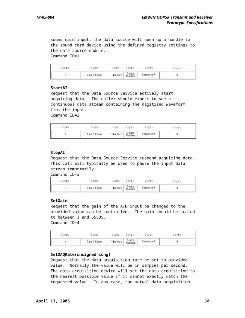
The only required commands, which must be implemented, include OpenDataSource, CloseDataSource, StartAI, and StopAI.
OpenDataSource Requests that the data source Attempt to open a connection to the input device, and initialize it appropriately. For a sound card input, the data source will open up a handle to the sound card device using the defined registry settings to the data source module.Command ID=1
StartAIRequest that the Data Source Service actively start acquiring data. The caller should expect to see a continuous data stream containing the digitized waveform from the input.Command ID=2
StopAIRequest that the Data Source Service suspend acquiring data. This call will typically be used to pause the input data stream temporarily.Command ID=3
SetGain
April 13, 2005 21

TR-05-004 EMWIN OQPSK Transmit and Receiver Prototype Specifications
Request that the gain of the A/D input be changed to the provided value can be controlled. The gain should be scaled to between 1 and 65535.Command ID=4
SetDAQRate(unsigned long)Request that the data acquisition rate be set to provided value. Normally the value will be in samples per second. The data acquisition device will set the data acquisition to the nearest possible value if it cannot exactly match the requested value. In any case, the actual data acquisition rate will be sent back through a status message indicating the actual sample rate.Command ID=5
SetBufferSizeRequest that the server return back the indicated buffer size for each data transfer to be performed. The actual buffer sizes across the TCP connection are limited to the TCP packet sizes, however, this setting will affect the size of the buffer which the A/D will use and thereby have a direct effect on pipeline delay, and possible CPU usage. The buffer size will be expressed in units of bytes. For example, if one wanted to specify 64K 16 bit samples per transfer, then the buffer size should be set to 128K bytes.Command ID=6
SetTimeOutThe timeout can be used to determine the maximum amount of time that the data source should remain blocked while waiting for the next buffer full of data. The timeout will be set in units of milliseconds.Command ID=7
ClearPendingOps
April 13, 2005 22

TR-05-004 EMWIN OQPSK Transmit and Receiver Prototype Specifications
A client calls this to request that the server clear any pending operations and remove data from all buffers.Command ID=8
InitializeDeviceCommand ID=9
CloseDataSourceCommand ID=10
ConfigStatus
A client can request constant status messages to be issued relating to the status of the A/D interface (IO) or the service status (SERVICE). If the StatusFlag field is less than or equal to 0, then this call will cancel status message reporting. When the StatusFlag is greater than 0, the Interval field determines the reporting interval of the requested status type. In this mode, the data source service will issue packets containing the requested information at the defined rate. The time interval unit is specified to be in seconds.
The text string field is defined to be a Pascal type string, where the first two bytes determine the length of the string, followed by the string contents.
Valid string content are IO, SERVICE…anything else will result in all status messages being reported. If the text string is not valid, or NULL, then both message types will be sent by default.
If the statusCommand ID=11
QueryStatus
A client can request constant status messages to be issued relating to the status of the A/D interface.Command ID=12
April 13, 2005 23

TR-05-004 EMWIN OQPSK Transmit and Receiver Prototype Specifications
SetChannelCnt
A client can request the number of channels to record. Typically this will be used to get real data, or complex I and Q data.Command ID=13
4.4.4.3 Status Interface (developer information)
The status interface defines the status of the analog input device, and is used to determine the current operating status of the A/D converter. Such items as gain, and data acquisition rate, buffer size, and whether or not the device is currently active are part of the response structure. The status messages are defined to be sent from the A/D server to the A/D client. In General, all messages sent from the server to the client shall use the same ID field as the one sent to it from the client.
The relevant code snippet that queries the device for its status is as follows:typedef struct IRAWDataInterface{unsigned short Gain;unsigned long DAQRate;
unsigned long BufferSize;bool IsActive;
}
bool GetStatus(IRAWDataInterface &rStatus)
Normally, the A/D status would not be required, since a successful connection and a successful configuration will yield a steady stream of data. Just monitoring the data stream flow is usually adequate.
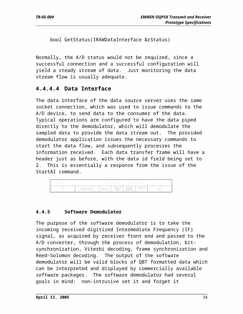
4.4.4.4 Data Interface
The data interface of the data source server uses the same socket connection, which was used to issue commands to the A/D device, to send data to the consumer of the data. Typical operations are configured to have the data piped directly to the demodulator, which will demodulate the sampled data to provide the data stream out. The provided demodulator application issues the necessary commands to start the data flow, and subsequently processes the information received. Each data transfer frame will have a header just as before, with the data id field being set to 2. This is essentially a response from the issue of the StartAI command.
April 13, 2005 24

TR-05-004 EMWIN OQPSK Transmit and Receiver Prototype Specifications
4.4.5 Software Demodulator
The purpose of the software demodulator is to take the incoming received digitized Intermediate Frequency (IF) signal, as acquired by receiver front end and passed to the A/D converter, through the process of demodulation, bit-synchronization, Viterbi decoding, frame synchronization and Reed-Solomon decoding. The output of the software demodulator will be valid blocks of QBT formatted data which can be interpreted and displayed by commercially available software packages. The software demodulator had several goals in mind: non-intrusive set it and forget it operation, ease of supporting different A/D hardware, flexibility in allowing users to connect to remote data acquisition hardware through a TCP/IP connection. The software design chosen to satisfy these goals include the following: all data acquisition and demodulator functionality will normally be run in the background as a Windows service. All configuration parameters can be set through the use of a control panel applet, modifying appropriate values in the registry. A/D hardware will be interfaced using a stand alone data source service, which will connect to the demodulation routines through a TCP/IP socket.
In the normal operations mode, there are just two software components that need to be running in order to produce the output data stream to either a TCP socket, or a serial port. The first service that needs to run is the data source service. The second required service is the demodulator service. The output of the demodulator service can be configured to produce valid data to either a TCP socket or a serial port. Snapshot below shows default settings.
April 13, 2005 25

TR-05-004 EMWIN OQPSK Transmit and Receiver Prototype Specifications
4.4.5.1 Data Source Host
Set this to the identity of the machine acting as the data source. Normally, this will be set to the local loop back setting of 127.0.0.1. However, one can use this setting to acquire data from a remotely located terminal acting as the data source.
4.4.5.1.1 TCP Port Number
Set this to the TCP port number which the data source host is set.
4.4.5.1.2 Signal Format
Valid signal formats are 0 and 1. 0 corresponds to the FSK 9600 service. 1 refers to the OQPSK 19.2 kbps service.
4.4.5.1.3 IQ Input
Enable this if the supplied IF adapter has IQ input. Normally should be enabled.
4.4.5.1.4 Server IP Bind
Use to bind the TCP server to a particular IP address. Typically this would be used in a multi-network enabled computer, and allows one to specify whether the TCP service
April 13, 2005 26

TR-05-004 EMWIN OQPSK Transmit and Receiver Prototype Specifications
should be bound to a particular IP address associated with different network interface cards.
4.4.5.1.5 COM Port Number
Set this to the serial port that one wants the output of the demodulator to be output. Legacy software requires COM inputs, so this allows a local cable loop back solution. Set to 0 or another invalid com port number to disable the output on the serial port.
4.4.5.1.6 TCP Port Number
Set this to the value for the TCP output port number. The demodulated data will appear as data on this port number in the QBT formatted data stream.
4.4.5.1.7 Packet Size
Set this to the value of the output packet size. Internal software requirements dictate that this value should be a multiple of 16.
4.4.5.1.8 Test Point
Determines the test point used to fill the debug data.
4.4.5.1.9 Debug Dump
When enabled, dumps the carrier tracker frequency and symbol tracker frequency to a file in a wave format.
4.4.5.1.10 RAW Source Host
See data source host for explanation.
4.4.5.1.11 RAW TCP Port
Use to set the TCP output port for raw symbols. Note that the raw symbols are directly out of the demodulator and are typically soft decision bits prior to any forward error correction applications.
4.4.5.1.12 Bits Per Symbol
Use to set the number of bits per symbol in the soft decision bits.
4.4.5.1.13 Hard Decision
When enabled, the soft decision bits are forced into hard decisions, and are output in packed format.
April 13, 2005 27
TR-05-004 EMWIN OQPSK Transmit and Receiver Prototype Specifications
4.4.5.1.14 Enable
Use this setting to enable RAW TCP output option. Normally, one would not be interested in the raw symbols, so leaving this off is desirable for most people.
4.4.5.1.15 Search Thresh
The search threshold determines the number of bit errors which are allowed in the attached frame synchronization marker. Normally in search, we want an exact match so that false frame synchronization locks don’t occur.
4.4.5.1.16 Check Thresh
When the frame synch is in the check or lock state, this setting determines the number of bit errors which are allowed in the attached frame synchronization marker. Typically, one would have this set to between 6 and 8 (out of 32 bits) for most of the expected operating conditions.
4.4.5.1.17 Check Frames
Sets the number of check frames which must be seen to kick the frame synch into a locked state. Normal operations will dictate a value of between 0 and 2.
4.4.5.1.18 Flywheel Frames
April 13, 2005 28

TR-05-004 EMWIN OQPSK Transmit and Receiver Prototype Specifications
After a failed lock state check occurs, determines the number dead reckoning frames which will be allowed before a failure is declared and the frame synchronizer is kicked into the search state.
4.4.5.2 FSK Demodulator Settings
The flow through the FSK demodulator is shown here. The input to the demodulator is either complex or real values. The demodulator uses standard techniques to demodulate the signal, yet allows for some flexibility in the specific details of the received signal. The following diagram also helps when detailed setting changes are made. In general, it is suggested that many of the default settings be left alone, since some thought and testing has gone into choosing the default values, and changing them without fully understanding the impact is likely to cause a decrease in performance.
The settings shown below are the EMWIN-OQPSK S/W default configurations and is the recommended reference or starting point for all configurations.
April 13, 2005 29

TR-05-004 EMWIN OQPSK Transmit and Receiver Prototype Specifications
4.4.5.2.1 Sample Rate
The front end sample rate needs to be set to the nominal A/D sample rate. Under normal circumstances, the A/D sample rate will be 48 KHz for a sound card solution. If the parameter is different, then it needs to be set accordingly. It must be stressed that the minimum sample rate needs to be high enough to capture the entire bandwidth of the full signal. For normal circumstances, the minimum A/D needs to be set at 44.1 KHz or higher. The units of this parameter are in hertz.
4.4.5.2.2 Signal Present Threshold
This setting determines the threshold which is used to indicate whether a valid signal is being presented to the demodulator. The parameter is specified in terms of full scale voltage. The default setting is 0.002 or 0.2 % of full scale (voltage), or -54 dB from full scale.
4.4.5.2.3 Side Lobe Ratio
The side lobe ratio setting is used to determine whether or not the demodulator appears to be tuned to a modulation side-lobe instead of the real signal. The side lobe detector compares the RMS voltage presented at the front end of the receiver, to the RMS voltage at the backend of the low and high side “tuners” (essentially matched filters for the 0 and 1 symbols if everything is ok). If the observed ratio is not at least as high as the value set
April 13, 2005 30
TR-05-004 EMWIN OQPSK Transmit and Receiver Prototype Specifications
by this parameter, then it will be assumed that the signal is not locked onto the correct frequency, and will force the receiver into acquisition mode. This parameter is expressed as a linear ratio in the voltage domain.
4.4.5.2.4 AGC Gain
The AGC gain is the gain bandwidth setting. The value listed corresponds to about a 1 Hz bandwidth at the given input sample rate, which is near the minimum. If for some reason a users terminal experiences faster fading (which is not expected under for stationary installations), then this parameter can be adjusted to a larger bandwidth setting to improve the response of the receiver if required.
4.4.5.2.5 Decimation Ratio
The decimation ratio is used to decimate the input to be compatible with the bandwidth of the signal. For sound card solutions, it is set to one. The implementation of the decimation filter is not without computational burden, and as a result, it is currently disabled in the version 1.0 release. If there is demand at a later date, then it can be enabled for users wishing to sample at a higher frequency, and needing to decimate the front end samples.
4.4.5.2.6 Tuner Frequency
This parameter specifies the initial tuner frequency, and represents the frequency as seen by the A/D converter. The nominal center frequency has been designed for approximately 0 KHz, which is in the center of the pass band of the software receiver using the illustrated sound card. This parameter normally should be set to a value which is near the observed frequency to speed signal acquisition time, since this is an auto tracking receiver. It is also used as the tuner frequency set point if one disables the automatic carrier tracker function. This capability allows users to use their own version of an IF.
4.4.5.2.7 FSK Delta F
This setting determines the FSK symbol frequency spacing in Hertz. In the example, the FSK symbols are spaced approximately +\- 3500 Hz for the 9600 baud EMWIN downlink.
4.4.5.2.8 Enable LPF
Enables or disables the filtering function for the low and high side filter banks. This setting needs to be enabled for normal operations, and should only be used for debugging purposes.
April 13, 2005 31
TR-05-004 EMWIN OQPSK Transmit and Receiver Prototype Specifications
4.4.5.2.9 Low Filter Bank
The low filter bank controls the low frequency filter bank setting for the low frequency symbol. Valid numbers range from 0 to 19, which correspond to approximate bandwidths of {0.005, 0.075, 0.085, 0.1, 0.125, 0.15, 0.175, 0.2, 0.225, 0.25, 0.275, 0.3, 0.325, 0.35, 0.375, 0.4, 0.425, 0.45, 0.475) scaled by the sample rate at that point in the signal chain.
4.4.5.2.10 High Filter Bank
The high filter bank settings are identical to the low filter bank settings, except apply to the high side symbol.
4.4.5.2.11 Enable Carrier Tracker
Enables the carrier tracker feed back loop.
4.4.5.2.12 Input Select Enable
When enabled, off symbol samples are replaced with 0’s instead of their corresponding values out of the filtered output.
4.4.5.2.13 Decimation Ratio
Determines the sample rate decimation ratio for the carrier tracker feed back loop only.
4.4.5.2.14 Signal Present Threshold
Use to set the value which must be detected in each of the 0 and 1 symbols which must be obtained in order to declare that the frequency is locked onto a valid signal.
4.4.5.2.15 Enable LPF
Use to enable the low pass filtering of the frequency detector output before closing the carrier tracker loop.
4.4.5.2.16 High Filter Bank
Use to specify the filter bank for the carrier tracker input. Valid values are between 0 and 19.
4.4.5.2.17 Low Filter Bank
Use to specify the filter bank for the carrier tracker input. Valid values are between 0 and 19.
April 13, 2005 32

TR-05-004 EMWIN OQPSK Transmit and Receiver Prototype Specifications
4.4.5.2.18 Acquisition Lead
Use to determine the carrier tracker lead gain, when in acquisition mode.
4.4.5.2.19 Acquisition Lag
Use to determine the carrier tracker lag gain, when in acquisition mode.
4.4.5.2.20 Track Lead
Use to determine the carrier tracker lead gain, when in track mode.
4.4.5.2.21 Track Lag
Use to determine the carrier tracker lag gain, when in track mode.
4.4.5.2.22 Minimum Frequency
Use to determine the minimum frequency that the carrier tracker will search for the signal of interest. This setting may need to be adjusted based upon the stability of the users receive chain. The default value assumes an accuracy of 5000 Hz.
4.4.5.2.23 Maximum Frequency
Use to determine the maximum frequency that the carrier tracker will search for the signal of interest. This setting may need to be adjusted based upon the stability of the users receive chain. The default value assumes an accuracy of 5000 Hz.
4.4.5.2.24 Sweep Rate
Use to determine how fast the sweeper unit sweeps across the frequencies which in acquisition mode. A too fast sweep rate will cause the module to never lock onto the signal of interest, while a too slow sweep rate will take too long to converge.
April 13, 2005 33

TR-05-004 EMWIN OQPSK Transmit and Receiver Prototype Specifications
4.4.5.3 FSK Symbol Settings
Typical FSK symbol recovery settings.
4.4.5.3.1 Acquisition Lead Gain
Use to determine the gain lead gain when in acquisition mode.
4.4.5.3.2 Acquisition Lag Gain
Use to determine the lag gain when in acquisition mode.
4.4.5.3.3 Track Lead Gain
Use to determine the lead gain when in track mode.
4.4.5.3.4 Track Lag Gain
Use to determine the lag gain when in track mode.
April 13, 2005 34

TR-05-004 EMWIN OQPSK Transmit and Receiver Prototype Specifications
4.4.5.3.5 Error Threshold
Use to set the maximum error that can be observed during the integration time for an in-lock condition to be declared.
4.4.5.3.6 Error Integration Time
Use to set the integration time in samples, which determines how long to integrate before declaring in-lock or out-of-lock conditions.
4.4.5.3.7 Enable LPF
Use to enable the low pass filters specified below.
4.4.5.3.8 Filter Bank
Use to set the filter effective filter bank for symbol formation. Normally, this should only be adjusted when changing the front-end sample rate.
4.4.5.3.9 Re-sampler Cutoff
Use to set the cut-off frequency of the symbol tracker re-sampler filter. Normally, this value would only need to change if one is changing the sampling rate.
4.4.5.3.10 Cutoff Transition
Specifies the excess bandwidth in a raised cosine spectrum.
4.4.5.3.11 Symbol Rate Minimum
Use to determine the minimum symbol rate which should be considered.
4.4.5.3.12 Symbol Rate Maximum
Use to determine the maximum symbol rate which should be considered.
4.4.5.3.13 Symbol Rate Sweep
Use to determine how fast the symbol tracker will sweep across the symbol rate when it is determined that the symbol tracker is actually in a search mode.
4.4.5.3.14 Symbol Rate
Use to set the nominal symbol rate. This value should be set to the nominal symbol rate in order to speed up the acquisition time.
April 13, 2005 35
TR-05-004 EMWIN OQPSK Transmit and Receiver Prototype Specifications
4.4.5.3.15 Enable Symbol Tracker
Use to enable the symbol tracker loop. Normally only should be disabled when attempting to study out of lock conditions, such as when new setting effects are being explored.
4.4.5.4 OQPSK Demodulator Parameters:
4.4.5.4.1 Sample Rate
The sample rate will typically be 48 KHz for the sound card solution.
4.4.5.4.2 Signal Present Threshold
The threshold used to indicate whether a valid signal is present.
4.4.5.4.3 Side Lobe Ratio
See FSK explanation
April 13, 2005 36

TR-05-004 EMWIN OQPSK Transmit and Receiver Prototype Specifications
4.4.5.4.4 AGC Gain
Adjusts how fast the AGC is varied. The default setting is approximately a 2 second time constant.
4.4.5.4.5 Tuner Frequency
Use to set the nominal frequency that the carrier tracker should be looking for the signal in Hertz. For a complex I&Q input, typically this value should be near 0 Hz. For a real valued solution, this should be set to the value nearest the expected if frequency, keeping in mind that the response of the sound card must pass the given IF frequency.
4.4.5.4.6 Frequency Minimum
Use to set the minimum frequency that the sweeper unit should cover when searching for the signal of interest. The units are in hertz.
4.4.5.4.7 Frequency Maximum
Use to set the maximum frequency that the sweeper unit should cover when searching for the signal of interest. The units are in hertz.
4.4.5.4.8 Frequency Sweep Rate
Use to set the sweep rate value. The optimum sweep rate value is affected by the EbN0 of the signal, and as such this value is only available when auto adjust thresholds is turned off.
4.4.5.4.9 Error Integration Time
Use to set the interval over which errors are integrated to determine whether the demodulator is locked onto the signal of interest. Longer periods of time insure more accurate readings when the signal is locked, but also take longer to respond to changing conditions. Normal operations see values ranging from 2000 to 8000 as good starting points.
4.4.5.4.10 Error Integration Threshold
Use to set the integration threshold of the error signal used for lock indication. If the value is exceeded, then the signal is in a locked condition (opposite of the FSK). Normally, this value will not be used if the auto threshold is enabled.
4.4.5.4.11 Verify Interval
Use to set the duration of the lock verification interval. The verification interval is only used when the state is changing from acquire to locked.
April 13, 2005 37

TR-05-004 EMWIN OQPSK Transmit and Receiver Prototype Specifications
4.4.5.4.12 Decimation Ratio
Use to determine the decimation ratio of the signal into the carrier tracker loop. Normally should be set to 1.
4.4.5.4.13 Filter Bank
Use to determine the low pass filter bank used prior to phase determination to limit the noise into the carrier tracker second order loop filter. A lower value lowers the noise bandwidth, and produces a more reliable result.
4.4.5.4.14 Enable LPF
Use to enable the use of the low pass filter as described above.
4.4.5.4.15 Carrier PLL Settings
These settings affect the bandwidth of the carrier tracker loop in both the acquisition and track mode. The default values are good one and should typically not be changed. Approximate values are provided below for the given bandwidths. The values indicate near critical damped loops, and one can make adjustments in either direction to affect the convergence rates.
BW Lead Lag6 130 5
12.8 175 1022 300 20
31.9 400 3038.3 480 60
46 580 8055.2 700 100
95 1250 350
4.4.5.4.16 False Lock Settings
Currently not implemented for the OQPSK signal, and should be left in the default state.
4.4.5.4.17 Auto Adjust Thresholds
Use to enable automatic adjustments of the carrier tracker sweep rate, and the carrier tracker lock error threshold depending upon the estimated Eb/N0. The estimated Eb/N0 uses power based arguments to determine the Eb/N0, and depends directly on an accurate indication of the noise bandwidth, or more precisely the sound card bandwidth.
April 13, 2005 38

TR-05-004 EMWIN OQPSK Transmit and Receiver Prototype Specifications
4.4.5.4.18 Enable Carrier Tracker
Should always be left in the enabled position, and is only useful for testing purposes.
4.4.5.4.19 A/D Bandwidth (Hz)
Set to the soundcard bandwidth in hertz. This is used to estimate the Eb/N0 of the received signal, and needs to be set to the value for the given sound card. Typically, either the default value will work, or a value near 37000 Hz will work for sound cards operating at 44.1 kHz. When properly adjusted, the estimated Eb/N0 as reported by the demodulator will be 3.6 dB above the Viterbi estimated Es/N0.
4.4.5.4.20 Symbol Track Gain Settings
Same basic functions as in the carrier tracker, except these settings determine the gains for the symbol recovery loops. The approximate values are given below with their
April 13, 2005 39

TR-05-004 EMWIN OQPSK Transmit and Receiver Prototype Specifications
corresponding bandwidths. It should be stressed that the symbol tracking bandwidth should normally be smaller than the carrier tracking bandwidth by an order of magnitude.
BW Lead Lag0.87 600 101.75 850 20
3.9 1650 504.9 2010 807.1 2800 20010 3856 49115 5300 1048
17.3 6500 1400
4.4.5.4.21 Matched Filter Settings
Use to set the filter bandwidth necessary to match the transmitted spectrum. Normally, the frequency cutoff will be set to the ¼ of the symbol rate divided by the sample rate. The cutoff transition is the excess bandwidth parameter for a RRC filter if it is positive. When the cutoff transition is negative, the transition follows the gain pattern of a sixth order Butterworth filter. The low pass filter bank is used to limit the noise into the symbol tracker loop, and doesn’t directly affect the symbol decisions.
4.4.5.4.22 Symbol Rate Settings
Use to specify the number of symbols that are transmitted in one second, and the limits of the sweeper search and the sweeper rate.
4.4.6 Dynamic Link Libraries (developer’s pack)
There are two dynamic link libraries which are included, and are actually used by the services described earlier. A test application is provided as part of the developer’s installation package, which has been compiled using Visual C++ 6.0. The example code contained in the TestDll application illustrates how to configure and use the dynamic link libraries. The configuration parameters map directly into the ones contained in the control panel applet, which has been described in this document. Setting these values has the same affect as changing them in the control panel applet.
April 13, 2005 40