Empowering and Assisting Natural Human Mobility: The...
17
Abstract This paper presents the complete development of the Simbiosis Smart Walker. The device is equipped with a set of sensor subsystems to acquire user-machine interaction forces and the temporal evolution of user’s feet during gait. The authors present an adaptive filtering technique used for the identification and separation of different components found on the human-machine interaction forces. This technique allowed isolating the components related with the navigational commands and developing a Fuzzy logic controller to guide the device. The Smart Walker was clinically validated at the Spinal Cord Injury Hospital of Toledo - Spain, presenting great acceptability by spinal chord injury patients and clinical staff. Keywords Assistive technologies, Smart Walkers, Natural mobility 1. Introduction 1.1 Human mobility and affections Mobility is one of the most important human faculties. It affects not only the individual’s locomotion capacity but also the ability to perform certain tasks, affecting physiological and personal aspects and conditioning the conduct of an individual in his/her environment. Different types of pathologies, such as poliomyelitis, spinal cord injuries, multiple sclerosis or trauma, affect the human mobility at different levels causing partial or total loss of such faculty. In addition, it is know that mobility decreases gradually with age as a consequence o neurological, muscular and/or osteoarticular deterioration. Several people need devices to replace, maintain, recover and empower the individual’s locomotion capacities. In this manner, the selection of an individual’s mobility assistive device should be taken according to the pathology and to the degree of illness or physical disability of the individual, (17). 1.2 Mobility assistive devices Considering the several types of conditions that affect human mobility it is necessary to take into account the level of motor impairment during the selection of a technical aid. In case of total incapacity of mobility, standing and locomotion, alternative solutions such as wheelchairs or special vehicles (e.g. scooters) should be addressed. Some examples of alternative devices are presented in Fig. 1. The robotic wheelchairs have been an intense focus of research during the last two decades. Autonomous and assisted navigation using several types of human-machine interfaces (HMIs) have been proposed in order to restore locomotion in many rehabilitation scenarios. Such researches have proposed a wide discussion in the scientific community and formed a Empowering and Assisting Natural Human Mobility: The Simbiosis Walker Regular Paper Anselmo Frizera-Neto 1,* , Ramón Ceres 2 , Eduardo Rocon 3 and José Luis Pons 4 1 Electrical Engineering Department, Federal University of Espírito Santo, Brazil 2,3,4 Bioengineering Group, Consejo Superior de Investigaciones Científicas, Spain *Corresponding author E-mail: [email protected] Received 24 February 2011; Accepted 02 March 2011 Int J Adv Robotic Sy, 2011, Vol. 8, No. 3, Special Issue Assistive Robotics, 34-50 www.intechweb.org
Transcript of Empowering and Assisting Natural Human Mobility: The...

Empowering and Assisting NaturalHuman Mobility: The Simbiosis Walker
Anselmo Frizera-Neto1, Ramón Ceres2, Eduardo Rocon3 and José Luis Pons4
1Electrical Engineering Department, Federal University of Espírito Santo, Brazil2, 3, 4Bioengineering Group, Consejo Superior de Investigaciones Científicas, Spain
Abstract This paper presents the complete developmentof the Simbiosis Smart Walker. The device is equippedwith a set of sensor subsystems to acquire user-machineinteraction forces and the temporal evolution of user’s feetduring gait. The authors present an adaptive filteringtechnique used for the identification and separationof different components found on the human-machineinteraction forces. This technique allowed isolating thecomponents related with the navigational commands anddeveloping a Fuzzy logic controller to guide the device.The Smart Walker was clinically validated at the SpinalCord Injury Hospital of Toledo - Spain, presenting greatacceptability by spinal chord injury patients and clinicalstaff.
Keywords Assistive technologies, Smart Walkers, Naturalmobility
1. Introduction
1.1 Human mobility and affections
Mobility is one of the most important human faculties.It affects not only the individual’s locomotion capacitybut also the ability to perform certain tasks, affectingphysiological and personal aspects and conditioning theconduct of an individual in his/her environment.
Different types of pathologies, such as poliomyelitis,
spinal cord injuries, multiple sclerosis or trauma,affect the human mobility at different levels causingpartial or total loss of such faculty. In addition, itis know that mobility decreases gradually with ageas a consequence o neurological, muscular and/orosteoarticular deterioration.
Several people need devices to replace, maintain, recoverand empower the individual’s locomotion capacities. Inthis manner, the selection of an individual’s mobilityassistive device should be taken according to the pathologyand to the degree of illness or physical disability of theindividual, (17).
1.2 Mobility assistive devices
Considering the several types of conditions that affecthuman mobility it is necessary to take into account thelevel of motor impairment during the selection of atechnical aid. In case of total incapacity of mobility,standing and locomotion, alternative solutions such aswheelchairs or special vehicles (e.g. scooters) shouldbe addressed. Some examples of alternative devicesare presented in Fig. 1. The robotic wheelchairs havebeen an intense focus of research during the last twodecades. Autonomous and assisted navigation usingseveral types of human-machine interfaces (HMIs) havebeen proposed in order to restore locomotion in manyrehabilitation scenarios. Such researches have proposed awide discussion in the scientific community and formed a
Int J Adv Robotic Sy, 2011, Vol. 8, No. 3, Special Issue Assistive Robotics, 34-5034
Empowering and Assisting NaturalHuman Mobility: The Simbiosis WalkerRegular Paper
Anselmo Frizera-Neto1,*, Ramón Ceres2, Eduardo Rocon3 and José Luis Pons4
1 Electrical Engineering Department, Federal University of Espírito Santo, Brazil2,3,4 Bioengineering Group, Consejo Superior de Investigaciones Científicas, Spain*Corresponding author E-mail: [email protected]
Received 24 February 2011; Accepted 02 March 2011
Int J Adv Robotic Sy, 2011, Vol. 8, No. 3, Special Issue Assistive Robotics, 34-50 www.intechweb.org

doctrine body, the Autonomous Robotic Wheelchairs, ARW.Some examples of ARW are adressed in section 1.2.1 alongwith some types of special vehicles.
It is known that the continuous use of wheelchairs cancause problems as such as joint stiffness, skin ulcerations,deformities in the spinal cord and physiologicaldysfunctions, all related to remaining in a seated positionfor long periods of time. For such reasons, the use ofalternative devices should be avoided if the user presentscertain locomotion capabilities preserved. Disabled people
are usually encouraged by the rehabilitation staff to useaugmentative devices which aim to empower the user’snatural means of locomotion, the lower limbs, takingadvantage of the remaining motor capabilities. Thissecond group of rehabilitation devices can be classifiedinto wearable - orthoses and prostheses - or externaldevices - canes, crutches and walkers Fig. 2 and Fig. 3.Currently, the augmentative devices are also a great focusof research and advanced / robotic solutions can be easilyfound in the literature. In section 1.2.2, some examples ofadvanced augmentative mobility devices are presented.
(a) Wheelchair, manual traction. (b) Wheelchair, electric traction. (c) Scooter.
Figure 1. Some examples of alternative mobility devices.
(a) Knee orthosis. (b) Leg prosthesis.
Figure 2. Some examples of wearable augmentative mobility devices.
(a) Cane. (b) Crutches. (c) Two-wheeled walker.
Figure 3. Some examples of external augmentative mobility devices.
2Int J Adv Robotic Sy, 2011, Vol. 8, No. 3, Special Issue Assistive Robotics, 34-5035
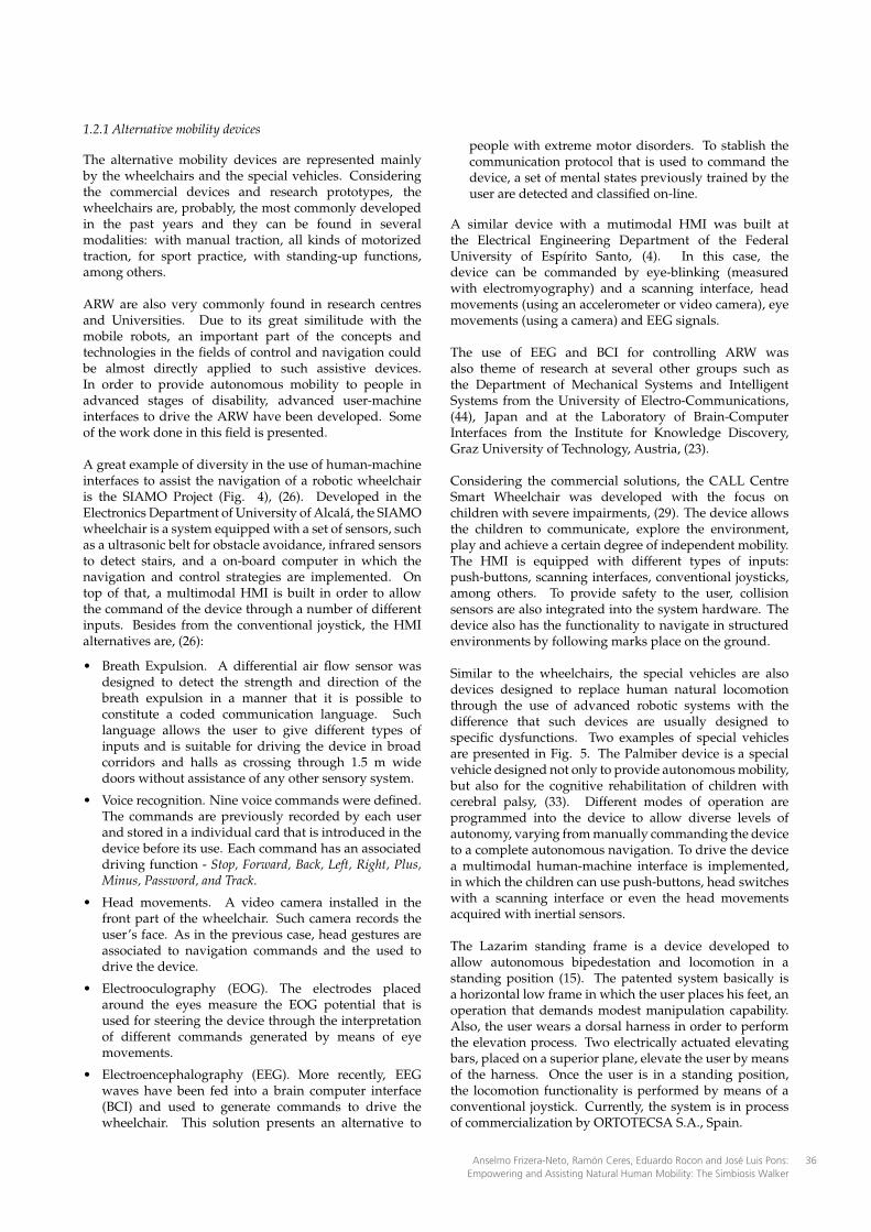
1.2.1 Alternative mobility devices
The alternative mobility devices are represented mainlyby the wheelchairs and the special vehicles. Consideringthe commercial devices and research prototypes, thewheelchairs are, probably, the most commonly developedin the past years and they can be found in severalmodalities: with manual traction, all kinds of motorizedtraction, for sport practice, with standing-up functions,among others.
ARW are also very commonly found in research centresand Universities. Due to its great similitude with themobile robots, an important part of the concepts andtechnologies in the fields of control and navigation couldbe almost directly applied to such assistive devices.In order to provide autonomous mobility to people inadvanced stages of disability, advanced user-machineinterfaces to drive the ARW have been developed. Someof the work done in this field is presented.
A great example of diversity in the use of human-machineinterfaces to assist the navigation of a robotic wheelchairis the SIAMO Project (Fig. 4), (26). Developed in theElectronics Department of University of Alcalá, the SIAMOwheelchair is a system equipped with a set of sensors, suchas a ultrasonic belt for obstacle avoidance, infrared sensorsto detect stairs, and a on-board computer in which thenavigation and control strategies are implemented. Ontop of that, a multimodal HMI is built in order to allowthe command of the device through a number of differentinputs. Besides from the conventional joystick, the HMIalternatives are, (26):
• Breath Expulsion. A differential air flow sensor wasdesigned to detect the strength and direction of thebreath expulsion in a manner that it is possible toconstitute a coded communication language. Suchlanguage allows the user to give different types ofinputs and is suitable for driving the device in broadcorridors and halls as crossing through 1.5 m widedoors without assistance of any other sensory system.
• Voice recognition. Nine voice commands were defined.The commands are previously recorded by each userand stored in a individual card that is introduced in thedevice before its use. Each command has an associateddriving function - Stop, Forward, Back, Left, Right, Plus,Minus, Password, and Track.
• Head movements. A video camera installed in thefront part of the wheelchair. Such camera records theuser’s face. As in the previous case, head gestures areassociated to navigation commands and the used todrive the device.
• Electrooculography (EOG). The electrodes placedaround the eyes measure the EOG potential that isused for steering the device through the interpretationof different commands generated by means of eyemovements.
• Electroencephalography (EEG). More recently, EEGwaves have been fed into a brain computer interface(BCI) and used to generate commands to drive thewheelchair. This solution presents an alternative to
people with extreme motor disorders. To stablish thecommunication protocol that is used to command thedevice, a set of mental states previously trained by theuser are detected and classified on-line.
A similar device with a mutimodal HMI was built atthe Electrical Engineering Department of the FederalUniversity of Espírito Santo, (4). In this case, thedevice can be commanded by eye-blinking (measuredwith electromyography) and a scanning interface, headmovements (using an accelerometer or video camera), eyemovements (using a camera) and EEG signals.
The use of EEG and BCI for controlling ARW wasalso theme of research at several other groups such asthe Department of Mechanical Systems and IntelligentSystems from the University of Electro-Communications,(44), Japan and at the Laboratory of Brain-ComputerInterfaces from the Institute for Knowledge Discovery,Graz University of Technology, Austria, (23).
Considering the commercial solutions, the CALL CentreSmart Wheelchair was developed with the focus onchildren with severe impairments, (29). The device allowsthe children to communicate, explore the environment,play and achieve a certain degree of independent mobility.The HMI is equipped with different types of inputs:push-buttons, scanning interfaces, conventional joysticks,among others. To provide safety to the user, collisionsensors are also integrated into the system hardware. Thedevice also has the functionality to navigate in structuredenvironments by following marks place on the ground.
Similar to the wheelchairs, the special vehicles are alsodevices designed to replace human natural locomotionthrough the use of advanced robotic systems with thedifference that such devices are usually designed tospecific dysfunctions. Two examples of special vehiclesare presented in Fig. 5. The Palmiber device is a specialvehicle designed not only to provide autonomous mobility,but also for the cognitive rehabilitation of children withcerebral palsy, (33). Different modes of operation areprogrammed into the device to allow diverse levels ofautonomy, varying from manually commanding the deviceto a complete autonomous navigation. To drive the devicea multimodal human-machine interface is implemented,in which the children can use push-buttons, head switcheswith a scanning interface or even the head movementsacquired with inertial sensors.
The Lazarim standing frame is a device developed toallow autonomous bipedestation and locomotion in astanding position (15). The patented system basically isa horizontal low frame in which the user places his feet, anoperation that demands modest manipulation capability.Also, the user wears a dorsal harness in order to performthe elevation process. Two electrically actuated elevatingbars, placed on a superior plane, elevate the user by meansof the harness. Once the user is in a standing position,the locomotion functionality is performed by means of aconventional joystick. Currently, the system is in processof commercialization by ORTOTECSA S.A., Spain.
3 Anselmo Frizera-Neto, Ramón Ceres, Eduardo Rocon and José Luis Pons: Empowering and Assisting Natural Human Mobility: The Simbiosis Walker
36

Figure 4. Some ARW developed under the framework of theSIAMO Project.
(a) Palmiber. (b) Lazarim.
Figure 5. Special vehicles.
1.2.2 Augmentative mobility devices
As previously mentioned, there are two types ofaugmentative devices: wearable and external.
During the past years there has been a great researchinterest on the wearable robots, not only for rehabilitationand functional compensation purposes, but also forempowering human capabilities in healthy subjects, (31).These were originally called extenders and were definedas a class of robots that extends the strength of the humanhand beyond its natural ability while maintaining humancontrol of the robot, (20).
Considering the rehabilitation and functionalcompensation scenarios, orthotic robots and prostheticrobots are found. An orthosis is a mechanical structurethat maps on to the anatomy of the human limb. Itspurpose is to restore lost or weak functions, e.g. followinga disease or a neurological condition, to their naturallevels. The robotic counterparts of orthoses are roboticexoskeletons. In this case, the function of the exoskeletonis to complement the ability of the human limb andrestore the handicapped function. A prosthesis is anelectromechanical device that substitutes for lost limbsafter amputation. The robotic counterparts of prosthesestake the form of electromechanical wearable robotic limbsand make it possible to replace the lost limb function ina way that is closer to the natural human function. Thisis achieved by intelligent use of robotics technologies interms of human-robot interaction (comprising sensing andcontrol) and actuation (32).
The Otto Bock C-Leg prosthetic knee is an example ofa state-of-the-art active prosthesis. It includes multiple
sensors that transmit information at a speed of 50 Hz,allowing the feedback controller to operate its mechanicaland hydraulic systems. Two strain gauges measurepressures on the leg and determine how often the heelstrikes (thus giving an estimation of the walking cadence);magnetic sensors report changes in knee angle.
The Prolite™ Smart Magnetix™ , manufacturedby Biedermann OT Vertrieb, a German maker ofprosthetic components, was developed jointly with LordCorporation. The system includes both kinetic (forceand torque) and kinematic (angular position and rate)sensors. The sensors are used to adapt the rheologicalcharacteristics of a modified Lord RD-1005 MR fluiddamper, (27).
The system incorporates controllers that adapt thedamping characteristics of the damper to the walkingconditions. Thanks to the fast response time of thetechnology, this adaptation can be made very quickly (ata rate of 500 Hz), allowing for a more natural gait andmaking climbing up and down stairs and slopes mucheasier. Moreover, it makes for a more efficient walkingpattern, which is one of the most serious problems sufferedby users of passive prostheses, (27). Fig. 6 (a) shows aprosthesis user walking down a slope with the Prolite™Smart Magnetix™ fitted.
An example of orthosis for functional compensation isthe GAIT exoskeleton (28), shown in Fig. 6 (b). In suchdevice, inertial information obtained from gyroscopes andaccelerometers is fused to obtain limb orientation and tocommand a set of electromechanical actuators that assistthe user’s lower limb during gait.
External devices, such as crutches, canes and walkersare very commonly found in daily life. There aremany variations of such devices according to theuser’s necessities, such as, patient’s cognitive function,judgement, vision, vestibular function, upper bodystrength, physical endurance, and living environment,(45). Nevertheless, advanced or robotic versions of suchdevices are not as current as the wheelchairs. Usually,the robotic canes are more focused on assisting the user’snavigation than offering physical support.
(a) Prolite™SmartMagnetix™above-the-kneeprosthesis.
(b) GAIT orthosis.
Figure 6. Two examples of wearable augmentative devices.
4Int J Adv Robotic Sy, 2011, Vol. 8, No. 3, Special Issue Assistive Robotics, 34-5037

Figure 7. The SmartCane.
The SmartCane, (43), developed at the MassachusettsInstitute of Technology uses a force/torque sensor installedon the device’s handle to measure the interaction betweenthe user and the cane mounted on a mobile robot(Fig. 7). Such inputs are converted into velocityand direction information by means of an impedancecontrol implemented in a PC-104 mounted into the mobileplatform. The system also counts with a CCD camera toassist navigation in structured environments and a sonarsystem for the detection and avoidance of obstacles.
2. Assessing and empowering natural mobilityusing walkers
Another device also oriented to assist in user’s guidanceis the GuideCane, (6). Such device is designed for blinduser’s to help in the avoidance of obstacles. The device isequipped with ultrasonic sensors, motorized wheels anda embedded processing platform to control the device.The user provides the desired direction by means of athumb-operated mini joystick installed on the device’shandle. Additionally, the device is equipped with a GPSnavigation system to improve the guidance functionalityoutdoors.
Considering that the walkers are the main focus of thisarticle, they are addressed separately in the next section.
Walkers improve balance by increasing the patient’s baseof support, enhancing lateral stability,and supporting thepatient’s weight.
There are many types of walkers, considering theirconstitutive materials, accessories, sizes and structuralconfigurations. Nevertheless, an important aspect thatclassifies conventional walkers is the ground contactconfiguration. There are devices that only have legs, otherswith legs and wheels and, finally, three or four- wheeledwalkers, (13).
In addition, G. Lacey presents a complementaryclassification of the standard walkers in three major types,(21). Standard Walking Frames or Zimmer Frames, Fig.8 (a), are designed to provide a larger base of support toa person with lower limb weakness. Normally, these arefour-legged devices. Special attention must be paid to thecorrect height of the frame to ensure good posture duringgait.
Rollators, Fig. 8 (b), are walking frames with wheelsattached and there are many different configuration ofbase. Rollators are used where balance is the major
problem rather than weight bearing. They are also usedwhere upper limb strength is not sufficient to lift thewalking frame on a regular basis. This device should beused if the patient requires a larger base of support anddoes not rely on the walker to bear weight. If a patientapplies full body weight through the device, it could rollaway, resulting in a fall, (45).
Reciprocal Frames are devices similar to the StandardFrames except that the frame is hinged on either sideallowing the sides of the frame to be moved alternately,Fig. 8 (c). They are designed to accommodate a normalwalking pattern with opposite arm and leg movingtogether. They are also used in domestic homes wherespace is confined.
In addition to the three types of walkers previouslypresented, there are the Front-Wheeled Walkers, Fig. 8(d). These devices are a intermediary device betweenthe Zimmer frames and the Rollators. Wheels permitthe patient to maintain a more normal gait patternthan they would with a standard walker, but they alsodecrease stability. Van Hook et al. present a detailedstudy concerning the different types of walkers andtheir application to certain gait disorders, (45). Despitethe enhanced support and utility for weight bearing,walkers also have disadvantages. These include difficultymanoeuvring the device through doorways and congestedareas, reduction in normal arm swing, and poor posturewith abnormal flexion of the back while walking. Ingeneral, walkers should not be used on stairs, (45).Conventional walkers also present problems related tothe pushing energy required to move the device, the lackof stability and brake control (especially in Rollators) andthe possibility of collision with obstacles.
In this context, to solve the previously presented issues,robotic or advanced walkers are a great focus of researchin many groups, specially in the United States, Europeand Japan. Such devices - the Smart Walkers - aim atpotentiating user’s residual mobility capacities by meansof advanced human-machine interfaces and controlledguidance. The following section will introduce some of thework developed in this field and a functional classificationof the Smart Walkers.
2.1 Smart Walkers. Most significant devices, current trends andfunctional compensation strategies
The Smart Walkers provide assistance to the user atdifferent levels, depending on the user’s needs. Following,a functional classification of such devices is presented.After that, some examples of relevant devices found on theliterature are given.
2.1.1 Physical support
By its nature and the kind of aid in question, almost thetotality of the Smart Walkers has some kind of physicalsupport function among its characteristics. There aremanly two types of physical assistance: passive and active.
5 Anselmo Frizera-Neto, Ramón Ceres, Eduardo Rocon and José Luis Pons: Empowering and Assisting Natural Human Mobility: The Simbiosis Walker
38

(a) Zimmer frame. (b) Rollator. (c) Reciprocal frame. (d) Front-wheeledwalker.
Figure 8. Conventional walkers.
In this first case, the objective is to introduce mechanical orstructural enhancements to the device improving stabilityduring gait. Usually, the improvements performedconsist on the enlargement of base of the device or thebalanced placement of heavy elements (motors, batteries,electronics, etc.) at lower planes of the walker increasingthe dynamic stability.
Other passive change, not as commonly observed asthe presented before, can be the replacement of theconventional handles (hand grip) of the walker byforearm support platforms. This reduces the number ofunsupported degrees-of-freedom at the user’s arms andincreases the user’s partial body weight support. Thismakes the device easier to push and, by increasing thefriction component of the system, reduces the risks ofglide.
Other possible enhancement concerning the reduction ofgliding with the ground is the selection of materials withhigh coefficient of friction for the walker wheels.
Considering the walkers with three or four wheels, acommon problem is the control of the device’s free motion.More specifically, braking a conventional walker is a taskthat requires muscular strength, motor coordination andgood reaction time, considering that these devices usuallyhave a brake system similar to the installed on bicycles.If any of the before presented human faculties fail, thereis a risk of an excessive acceleration of the device and aconsequent fall.
In addition to the breaking problems, it is important toemphasize that the strength necessary to push the walkercan be high depending on the degree of disability of theuser. In this case, it is important to provide external andcontrolled pushing energy to the system.
Additionally, to prevent uncontrolled walker’s motion,active physical support are commonly found on mostof the Smart Walkers. Usually, these devices havemotors installed on their wheels that are able to controlthe brakes, compensate gravity on inclined groundsand provide the pushing energy necessary to movethe device. These motors are usually controlled by anadvanced human-machine interface capable of detecting
and interpreting the user’s commands and translate theminto motor actuation.
2.1.2 Sensory assistance
The Smart Walkers can also be used as elements to providesensorial assistance to the user.
Normally, this function is performed through theinstallation and processing of ultrasonic, vision or infraredsensors capable of detecting static and dynamic obstacles.The control system assists the user to avoid them be it bysound or vibration alerts or directly operating the device’sactuators, momentarily changing the path introduced bythe user.
Normally, such sensory assistance functions are designedto help users with visual problems or to help navigationon environments with multiple obstacles occluded, manytimes, by the device itself.
2.1.3 Cognitive assistance
In this group, there are found the devices that assistuser navigation and (auto-) localization in structuredenvironments and outsides (using GPS, for an example).These Smart Walkers are very important to people thathave cognitive issues and problems related to memoryloss and disorientation.
Some Smart Walkers are programmed to followedpredetermined paths inside clinics or achieve a certainlocation in a map of a house or medical facility. Otherdevices are capable of creating maps of an unknownenvironment or auto-localization in a map using markersplaced on the surroundings.
Also, some Smart Walkers can communicatebidirectionally with the user through a visual interfaceor voice commands, receiving directions from the user, orinforming the same about the present localization in a mapand the environment conditions, such as obstacles.
2.1.4 Health Monitoring
In more specific situations, Smart Walkers can be usedto monitor some health parameters of the user. Thishealth information is used to keep a medical history of the
6Int J Adv Robotic Sy, 2011, Vol. 8, No. 3, Special Issue Assistive Robotics, 34-5039

user or inform through a wireless communication networka health center or the medical staff in the case that anemergency situation is detected.
2.2 Relevant Smart Walkers found on the literature
Specially considering the elderly, walker can suffer frommultiple health conditions. In such cases, more than oneof the before mentioned functions are needed. For thatreason, many of the Smart Walkers on the literature aremultifunctional.A good example of a multifunctional walker is the Mobil,(7). The developed device is designed to offer extrasupport to the user through the use of forearm supportplatforms and motorized rear wheels. Also, it can becommanded by a remote control or follow the user ifhe/she uses an active belt that sends ultrasonic signals tothe walker. This walker uses a second set of ultrasonictransducers to detect and avoid static and dynamicobstacles, acting as a sensorial assistance device.
Nevertheless, the most representative Smart Walkers andreferenced in several scientific papers are the PAM-AID(with all its versions), PAMM SmartWalker and the MARCSmart Walker. Such devices, shown in Fig. 9, are presentedin the following paragraphs. The Personal AdaptiveMobility Aid (PAM-AID) is robotic mobility aid designedto augment the independence of people that have visualimpairments and mobility problems, (22). Several versionsof the PAM-AID Smart Walker were developed. Some ofthem are presented in Fig. 9 (a).
One of the main objectives of the PAM-AID is to offermaximum control of the platform to the user. In thismanner, the PAM-AID has no motorized locomotion. Theelectronic system only controls the orientation of the frontwheel, based on the guidance information acquired by anintuitive user interface. Such user interface is similar to thehandlebar of a bicycle that can rotate ±15◦. The handlebaris spring loaded and when no torque is applied it willreturn to its zero position.
To assist on the guidance of visually impaired people,the device is equipped with ultrasonic or laser sensorsdepending on the version of the device. Also, informationabout the environment state is provided by the walker inthe form of two types of voice messages: one regarding
the description of the environment and another messageinforming the user about the presence of obstacles.
The PAM-AID has two operation modes, (24). Thefirst one is the manual. In this case, the system nevercontrols the steering of the device, only providing thetwo types of voice messages. The second operationmode is the assistive, in which the device provides thevoice messages and, in addition, controls the front wheelavoiding obstacles.
In the year 2000, Haptica Ltd. started thecommercialization of the PAM-AID Smart Walker. TheDepartment of Veterans Affairs (USA) purchased fivedevices and introduced some minor modifications andevaluated the safety and performance of the device,renaming it as the Veterans Affairs Personal AdaptiveMobility Aid (VA-PAMAID), (34).
In another commercialization intent, the PAM-AID wasrenamed GUIDO Smart Walker, (41). The device becamemore aesthetically attractive, ergonomic and some newfunctions were included. A third mode of operation,parked mode, also present on the VA-PAMAID, wasintroduced. In such mode, the front wheel of the deviceis positioned to break it in order to assist the transferof the user from a chair. Map navigation, mappingand auto location techniques were also introduced,(40). Considering the user interface, the spring loadedhandlebar was replaced by force sensors used to identifynavigational intents of the user, (41).
Other relevant development is the Personal Aid forMobility and Monitoring (PAMM), (43). The PAMMcomes in two versions. The cane-based device (PAMMSmartCane) was previously presented in section 1.2.2.The Smart Walker version is shown on Fig. 9 (b). ThePAMM SmartWalker is designed to offer extra supportfor walking, guidance, scheduling (reminding the time totake medicines, for an example) and health monitoring forelderly users. The main idea is to provide a completesystem to help the elderly in the normal problems ofthe senility, such as loss of memory, disorientation,musculo-skeletal weakness, lack of stability during gaitand monitoring of vital signals such as electrocardiogram(ECG). Also, the device features enable it to be used asrehabilitation device for younger patients.
(a) PAM-AID (2 versions). (b) PAMMSmartWalker.
(c) MARC SmartWalker.
Figure 9. Some of the most representative Smart Walkers.
7 Anselmo Frizera-Neto, Ramón Ceres, Eduardo Rocon and José Luis Pons: Empowering and Assisting Natural Human Mobility: The Simbiosis Walker
40

The PAMM has a set continuous health monitoringsensors. These sensors can detect short term changesas well as long term health trends. It can record theuser’s activity level (speed and applied forces). Suchmeasurements can help physicians to better monitor theuser’s health during regular operation of the device. Arobust ECG-based pulse monitor was developed for theSmartWalker. Experiments were also performed usingthe force/torque sensor of the PAMM systems along withodometry information to study the user’s gait and to detectrisks of falls.
For the locomotion, the device is equipped with fourwheels; two of them are castor, and the other twomotorized omni-directional wheels. This way, the PAMMSmartWalker can move on a plane in any direction,improving the manoeuvrability in confined indoorsspaces. Three types of sensors are used in order to controlthe navigation of the device: a sonar array, a CCD cameraand tridimensional force/torque sensors. The sonar arrayinstalled on the front of the device is used in order toavoid obstacles. The CCD camera is used to detect marksplaced on the ceiling of a structured medical facility ornursing home. Finally, the force/torque sensors installedon the handle of the walker are used to capture the user’snavigational intents, the level of support and to determinestability parameters of the user when pushing the device.
An important question approached in this device is how togive the maximum control to the user taking into accountthe possible cognitive degenerations of the user. On theone hand, the PAMM walker can be fully guided bythe user, trough the application of forces/torques on thehandles of the device. On the other hand, it is capable ofnavigating automatically in a structured environment.
The solution adopted was a shared control algorithm thattakes a greater control of the device when the user starts todiverge from the path calculated by the electronic system.Initially, the user has to introduce a destination.
The system generates virtual forces/torques that areproportional to the deviation of the programmed path.Such forces and torques are added to the forces appliedby the user and an admittance controller converts theresultant forces and torques on motor velocity movingthe device.
The Medical Automation Research Center (MARC) SmartWalker, (47), is a device based on the modificationof a commercial three-wheeled walker, Fig. 9 (b).Tridimensional force/torque sensors were installed on thewalker’s handle to measure the interaction between userand the device. Based on the forces and torques applied,the current state of the walker and the environmentconditions (measured by sonar and infrared sensors), thecontrol architecture of the MARC Smart Walker estimatestwo signals called user intent and walker intent. Thecontrol logic balances these two signals in order to generatethe control of the orientation of the front wheel. Similar tothe PAM-AID, the MARC walker doesn’t have motorizedlocomotion. The pushing energy has to be supplied by the
user.
An interesting study was realized with the MARC walkerand a camera motion analysis system in order to determinegait characteristics from measured forces and moments,such as the heel strike, toe-off, double support, and single(differentiating from right and left foot) support detection,(3).
More recently, research projects are also focusing onthe development of systems to assist the bipedestationprocess. D. Chugo presents an advanced walker in thiscontext, (9), (10), (11). The user, at sitting position, placeshis/her arms on a supporting platform that is elevatedduring the standing process assisting the user in theoperation. Once in standing position, DC motors alsoassist the device’s navigation following user’s commands.
Similar to that, the devices named WHERE I and II weredeveloped focusing on different actuator technologies toassist the standing operation, (42). At this level, the SmartWalkers start to merge with other groups of devices, suchas the gait trainers, expanding the number of possibleusers and the rehabilitation scenarios.
3. The Simbiosis Walker. Concepts, implementationand clinical validation
In this section, the Simbiosis Walker is presented. Thedevice, developed under the research project with thesame acronym, focuses on enhancing comfort, safetyand stability during gait. This is proposed throughthe development of a multimodal HMI responsible forthe acquisition and interpretation of user’s postures andgestures during gait. Both upper and lower limbsinformation are combined in order to command thedevice’s motion. Such interaction signals are classified andturned into motor commands using fuzzy logic. Finally,the system was taken for experimental validation at theNational Hospital of Paraplegics - Toledo, Spain.
3.1 Simbiosis Project. Human-machine interaction concepts
The robotic walker developed under the framework ofthe Simbiosis Project presents two sensor subsystemsdesigned for the acquisition of gait parameters and forthe characterization of the human-robot interaction duringgait, (16). First, the upper-body force interaction subsystem, isbased on two tridimensional (3D) force sensors installedunder the forearm supporting platforms Each 3D forcesensor is compound by one MBA400-200Lb biaxial sensorby Futek and one Transdutec TPP-3/75 load cell withtheir respective amplifiers. The biaxial sensors are usedfor measuring the X (lateral direction) and Y (advancedirection) components. The load cells measure the Zcomponent (vertical direction).
The second subsystem is compound by ultrasonic (US)sensors to measure the user’s feet evolution duringassisted gait. One piezoelectric US receiver is installedon each user’s feet and an emitter is placed on the walkerstructure. Through direct transmission, the evolution of
8Int J Adv Robotic Sy, 2011, Vol. 8, No. 3, Special Issue Assistive Robotics, 34-5041

the distance between user’s feet and walker is measuredand several parameters regarding user’s gait and walkermotion are determined.
Figure 10 illustrates how both sensor subsystems areinstalled on the walker’s structure. Force and ultrasonicsensors are integrated into a real-time architecture basedon Matlab Real-Time xPC Target Toolbox. When datastorage is required (e.g. for offline studies), a laptopcomputer is also introduced into the system’s architecture.The laptop PC also adds the possibility to control thesystem externally through a wireless LAN remote desktopconnection.
During the first experiments performed with thedeveloped device, no motorized locomotion wasintroduced with the goal of characterizing the typicalsignals obtained from the multimodal interface. Thesubjects recruited for such experiments presented nohistory of any dysfunction on either upper or lower limbs.
A study regarding the forces acquired during experimentsof assisted gait lead to the identification of three maincomponents in force signals: the vibrations introducedby floor/walker wheels imperfections, oscillations due
to user’s trunk motion during gait and the voluntarycomponents related to the user’s navigational commands.This led to the development of a technique for obtainingand characterizing such components, (19).
Additionally, US distance signals were used forcharacterizing feet evolution, gait parameters and, mostimportantly, to improve the reliability of the filteringarchitecture developed for obtaining user’s guidancecommands, presented in the next section.
3.2 Adaptive real-time filtering for the identification of user’sguidance intentions
The typical force data acquired on the y axis of one of theforce sensors is presented in Fig. 11. As it is shown, inthe instants that the subject is not walking but has his/herarms resting on the forearm supports (green boxes in Fig.11), no high frequency noise is observed. This indicatesthat the high frequency components are generated duringthe movement of the device. As observed by the authors,such noise is caused by vibrations introduced by bothirregularities on the ground and imperfections on thesurface of the walker’s wheels.
Fy
Fz
Fx
US Emitter
USReceptor
Figure 10. The Simbiosis Walker and its subsystems
0 10 20 30 40 50 60 70Time [s]
Forc
e [k
gf]
−202468
10
Figure 11. Typical force signal (Y-axis) obtained experimentally.
Fij
Cadence
+-
Gait cadence component estimation
Cancelation ofhigh-frequency perturbations
F(cad) ij
F(lf) ij F(filt) ij
Figure 12. Filtering architecture presented in this work.
9 Anselmo Frizera-Neto, Ramón Ceres, Eduardo Rocon and José Luis Pons: Empowering and Assisting Natural Human Mobility: The Simbiosis Walker
42

3.2.1 High-frequency noise cancellation filter
In addition, during the moments in which the subject iswalking (red box, Fig. 11), slower oscillations are alsoobserved in all axis of force data. In previous works,the authors demonstrated that this oscillatory componentis specially observed in the vertical direction of theforce data, and is a result of the lateral displacementsof user’s trunk, (2). Such oscillations are translatedinto forearm reactions as the user is supported by thewalker. Movements of user’s trunk and, consequently,user’s center of gravity (CoG) are highly correlated withgait phases, (49). In (18) and (1), the authors proposeda methodology for the extraction of gait parameters,such as heel-strike, toe-off and cadence, from this forcecomponent.
Finally, other events related to user’s navigationcommands are also found within the force sensor datapreviously presented. Considering that force sensorswere installed in walker’s handles for the identificationand characterization of user’s guidance intentions, suchtransient components must be properly extracted in orderto generate commands that drive walker’s motion.
Next sections introduce a methodology for the extractionof the components related to user’s guidance intentions.Such methodology is based on the filtering diagrampresented in Fig. 12:
• The upper branch is designed for the cancelation ofhigh-frequency components that result from vibrationscaused by wheels/floor irregularities.
• The lower branch is constructed to estimate in real timethe component caused by user’s trunk oscillations and,therefore, highly correlated with user’s cadence. Thislast component is, then, subtracted from the force datafiltered by the first block.
As it can be seen, in addition to the force signals, cadenceis also an input for this filter. The idea is to selectivelyand adaptively filter the force data without compromisingthe amplitude of components which frequencies are closeto gait cadence as they can contain relevant informationregarding user’s intents. For that matter, a cadenceestimation method based on the US signals is alsopresented in section 3.2.3.
This section presents a filtering architecture that relieson the high-frequency of the force components relatedto the vibrations of the walker’s structure. As it is known,classical low-pass filters can be used for the cancellation ofhigh-frequency components of the acquired force signals.Nevertheless, such approach would also introduce animportant phase shift between input and outputs signalscausing a temporal delay on the filtered signal. Suchsituation is undesirable in real-time applications oncedelay affect the cognitive interaction between the walkerand the user.
To overcome such limitation, an approach based on g-hfilters is proposed. G-h filters are simple recursive filtersthat estimate future position and velocity of a variable
based on first order model of the process. Measurementsare used to correct these predictions, minimizing theestimation error. Traditional applications of g–h filtersare radar tracking and aeronautics, (8). The general formof a g–h filter is described in the following equations.
xk,k = xk,k−1 + gk(yk − xk,k−1) (1)
xk,k = xk,k−1 +hkTs
(yk − xk,k−1) (2)
xk+1,k = xk,k + Tsxk,k (3)
xk+1,k = xk,k (4)
Equations 1 and 2 are designated as update, tracking, orfiltering equations. They estimate the current position,xk,k, and velocity, xk,k, of the variable based on previouspredicted position, xk,k−1, and velocity, xk,k−1, taking thecurrent measurement yk into account. Confidence onmeasures is weighted by gains gk and hk. Equations 3 and 4are called prediction equations as they provide a predictionof future position and velocity, xk+1,k, xk+1,k, based on firstorder dynamic model of the variable. As g-h trackersconsider a constant velocity model, predicted velocityxk+1,k is equal to the current one, xk,k. The assumptionof constant speed is reasonable considering that humanmovements are slow, presenting small accelerations, (25),and that the data is sampled at high rates (in this study,fsampling = 1kHz).
G-h filters are affected by two error sources, (8): (i) the lag,dynamic, bias or systematic error, which are related to theconstant velocity assumption, and (ii) the measurementerror, which is inherent to the sensor and measurementprocess. Typically, the smaller gk and hk are, the larger isthe dynamic error and the smaller are the measurementerrors, (8). In designing a g-h tracking filter there is adegree of freedom in choice of the relative magnitude ofthe measurement and dynamic errors.
To simplify the selection of filter gains (gk, hk), two filtersthat are optimal in some sense are considered. Thesefilters are the Benedict-Bordner Filter (BBF) and theCritically Dampened Filter (CDF). BBF minimizes the totaltransient error, defined as the weighted sum of the totaltransient error and the variance of prediction error due tomeasurement noise errors, (5). BBF is the constant g-h filterthat satisfies:
h =g2
2 − g(5)
As g and h are related by Equation 5, the BBF has only onedegree of freedom.
CDF minimizes the least-squares fitting line of previousmeasurements, (8), giving old data lesser significancewhen forming the total error sum. This is achieved withweight factor θ. Parameters in the g-h filter are related byEquation 6. Selection of filter gain for the CDF is analogousto that for the BBF.
g = 1 − θ2 (6)
h = (1 − θ)2
10Int J Adv Robotic Sy, 2011, Vol. 8, No. 3, Special Issue Assistive Robotics, 34-5043

For the selection of the filter and for tuning of the thecorrespondent parameters, the Kinematic Estimation Error(KTE) was used, (Equation 7). KTE quantifies the transient
response through |ε|2 and, at the same time, the averagingof filtering capabilities of the filter through the term σ2, (39)
KTE =
√|ε|2 + σ2 (7)
Where, |ε| is the mean square of errors of the filteredsignal and σ2 is the variance both related to a referencesignal obtained through offline filtering the signal with thealgorithm known as zero-phase forward and reverse digitalfiltering, (30). This last filtering algorithm is non-causalonce the signal is filtered both in forward and reversedirections in time and it can be only used in offlineapplications. Nevertheless, it offers an optimal referencesignal for the proper selection of filter’s coefficients,considering that the filter yields precisely zero-phasedistortion.
The KTE was used for the selection of the filteringparameters for BBF and CDF: g and θ were modified withina broad range, using a small step, and the best solutionwas selected for each user, experiment and repetition invalidation experiments performed with healthy subjects.Mean KTE of (2.035 ± 0.358) · 10−2kg f and delay of(1.897 ± 0.3697) · 101ms were obtained for the BBF, whilemean KTE of (1.951 ± 0.350) · 10−1kg f and delay of(2.413 ± 0.131) · 101ms were obtained for the CDF. As theKTE in both cases are very similar and the delay is stillsignificantly smaller for the BBF, this filter showed to bea better solution than CDF for the data obtained from theexperiments performed in this work.
3.2.2 Estimation of force component related to gait cadence
Once the filter for cancelation of high-frequency noise isintroduced, this section presents a methodology for theestimation of the force component related with user’sgait cadence. For that purpose, taking advantage of theperiodicity of cadence, an adaptive filter based on theFourier Linear Combiner (FLC) was applied.
FLC is an adaptive algorithm used for continuousestimation of quasi-periodical signals based on a Mharmonics dynamic Fourier model (Equation 8). Usingfrequency and number of harmonics as inputs for themodel, the algorithm adapts amplitude and phase for eachharmonic at the given frequency.
s =M
∑r=1
[wrsin(rω0k) + wr+Mcos(rω0k)] (8)
The adaptation of the coefficients wk is performed based onthe least-mean-square (LMS) recursion, a descend methodbased on a special estimate of the gradient, (48), whichensures inherent zero phase. The equations for the FLCalgorithm are described below.
xrk =
{sin (rω0k) , 1 ≤ r ≤ Mcos ((r − M)ω0k) , M + 1 ≤ r ≤ 2M (9)
εk = yk − WTk Xk (10)
Wk+1 = Wk + 2µεkXk (11)
Where:
• yk is the input signal.• Wk is the adaptive weight vector that generates a linear
combination of the harmonic orthogonal sinusoidalcomponents of the reference input vector
• Xk is the reference input vector.• M is the number of the harmonics used in the model.• µ represents the amplitude adaptation gain used for the
LMS recursion.
As mentioned before, the FLC algorithm needs a frequencyinput for the correct estimation of the gait relatedforce component. Next section describes the developedmethodology for the real time estimation of gait cadence.
3.2.3 Real time estimation of gait cadence from ultrasonicsignals
The authors demonstrated in (18) that the verticalcomponents of the force signals can be used for continuousestimation of gait cadence using the Weighted-FrequencyFourier Linear Combiner (WFLC). Nevertheless, in thatapplication the algorithm needed to be tuned individuallyfor each subject.
Also, the experiments were performed in a controlledenvironment on top of a treadmill. In outdoors and,specially, dealing with a more diverse populationthe use of foot-walker distance signals experimentallydemonstrated to offer a more robust real time estimationof gait cadence. The WFLC method was adapted to thissituation.
Taking into account the typical form of the distance signalobtained (Fig. 13), the method for cadence estimation ispresented. The WFLC is an extension of the FLC noisecanceller presented before and also tracks frequency ofthe input signal based on a LMS recursion. Therefore,the WFLC adapts in real-time its amplitude, frequencyand phase to the reference signal, (37). It is based onIEEE-STD-1057, which is a standard for fitting sine wavesto noisy discrete-time observations. The WFLC is also builtupon the least-mean-square (LMS) recursion, a descendmethod based on a special estimate of the gradient, (48).This ensures it has inherent zero phase, thus allowing forreal-time implementation.
The WFLC recursion minimizes the error εk between theinput sk and the signal harmonic model, (12). It assumesthat the distance measured by the ultrasonic sensor canbe mathematically modelled as a pure sinusoidal signal offrequency ω0k plus M harmonics, (36).
εk = sk −M
∑r=1
[wrk sin
(rω0k k
)+ wr+Mk cos
(rω0k k
)](12)
11 Anselmo Frizera-Neto, Ramón Ceres, Eduardo Rocon and José Luis Pons: Empowering and Assisting Natural Human Mobility: The Simbiosis Walker
44

The WFLC provides an estimate of instantaneousfrequency:
ω0k+1 =ω0k − 2µεk∂εk
∂ω0k
(13)
∂εk∂ω0k
=− kM
∑k=1
[wrk cos
(r
k
∑t=1
ω0t
)
− wrk+M sin
(r
k
∑t=1
ω0t
)](14)
The WFLC is formulated as follows: (15) represents thesinusoidal signal model, which consists of M harmonicsof the fundamental frequency, ω0t . The error whichthe algorithm uses to adapt itself to the input signalis described in (16). Frequency and amplitude weightsupdate based on the LMS algorithm (48) are expressed in(17) and (18) respectively.
xrk =
sin(
r ∑kt=1 ω0t
), 1 ≤ r ≤ M
cos((r − M)∑k
t=1 ω0t
), M + 1 ≤ r ≤ 2M
(15)
εk = sk − WTk Xk − µb (16)
ω0k+1 = ω0k + 2µ0εk
M
∑r=1
r(wrk xM+rk − wM+rk xrk
)(17)
Wk+1 = Wk + 2µ1εkXk (18)
The algorithm has 5 parameters to be tuned: The numberof harmonics of the model, M, which is fixed to 1,
the instantaneous frequency at initialization, ω0,0, theamplitude and frequency update weights, µ0 and µ1, anda bias weight, µb, to compensate for low frequency drifts,(35).
As the WLFC is designed to adapt to thedominant-frequency component in a signal (38), it isimportant to perform a previous stage of band-passfiltering (compatible with gait cadence frequencies) for thecorrect performance of the WFLC. Although this filteringstage can cause undesirable time delay in the force signals,instantaneous temporal changes in gait cadence (WFLC’sfrequency output) are minimal. Therefore, an externalbranch of cadence estimation based force measurement,and the WFLC algorithm showed to be very useful in theapplication presented.
Thus, the combination of WLFC and FLC presents greatadvantages, (36). The band-pass filtering allows the WFLCto robustly adapt to the values of gait cadence, whilethe FLC operates on the raw input, ensuring zero-phaseamplitude estimation. Fig. 14 shows the complete diagramof the filtering architecture. The cadence estimation stage,here presented, is shown in the purple area.
As it is shown, each distance signal is filtered individuallyand the averaged to ensure good signal estimation. Theoutputs of the FLC block is connected depending whetherthe amplitude of the WFLC estimation signals are greaterthan a threshold (green area), indicating that there isa cadence signal. This is done due to the fact that azero signal can have any value of frequency and zeroamplitude.
7 7.5 8 8.5 9 9.5 10 10.5 11 11.50.2
0.4
0.6
0.8
1
time[s]
dist
ance
[m]
Figure 13. Typical foot-walker distance signal obtained from the ultrasonic system
WFLC
WFLC
++
Cadence estimation stage
+-FLC
dfoot-walkerright
leftdfoot-walker
*0.5
f
f2
f1
A1
A2
f(A1,A2)
FijF(cad) ij
BBFF(filt) ijF(lf) ij
Figure 14. Complete filtering architecture.
12Int J Adv Robotic Sy, 2011, Vol. 8, No. 3, Special Issue Assistive Robotics, 34-5045

−202468
10
−202468
10
0 10 20 30 40 50 60 70−202468
10
force
[kgf]
time[s]
Original force signal without the high-frequency noise component Force signal processed by BBFForce signal processed by the complete filtering method
Figure 15. Signals at different stages of the filtering architecture.
Once the complete filtering architecture was developed,values were set for the coefficients of the WFLC and FLCblocks. These values, obtained experimentally for healthysubjects, were:
• WFLC. M = 1, ω0,0 = 0.3 (the lower cut-off frequencyof the band-pass filter), µ0 = 3 · 10−5, µ1 = 1 · 10−3 andµb = 0.
• FLC. M = 2 and µ = 2 · 103
The authors would like to mention that the selection ofvalues for µ affects directly the convergence time and,most importantly, the bandwidth (BW) of the FLC adaptivefilter, (46). For values of µ � 1, the bandwidth is given byBW ≈ 2µ.
This filtering methodology led to an amplitudecancellation of approximately 80% of the gait relatedcomponents, (19). Fig. 15 presents the effect of the filteringmethod on the force signal introduced in Fig. 11. Thefiltered signal (red in Fig. 15) is used for guiding therobotic walker through the control strategy presented inthe next section.
3.3 Users’ intent classification and control strategy
The force signals filtered with the previously presentedalgorithm were used to drive the walker’s motion througha classifier and controller based on fuzzy logic. Figure 16illustrates the developed methodology. Both y-axis andz-axis force components from both right and left sensorsare filtered individually using the filtering architecturepresented in Fig. 14. Afterwords, y-components aredivided by the z-components in order to obtain forcesignals that are proportional to the amount of body weightapplied in each armrest. This feature is specially importantin cases of asymmetrical support caused by a unilateralaffection on gait. Then, signals are conditioned to enterthe fuzzy logic classifier by means of:
• a gain, to adjust to the correct range of inputs;• a saturation block, to avoid signals over the input limits
and• a dead-zone, to prevent motor commands in cases of
signals very close to zero and, thus, not high enough tomove the device.
After the fuzzy logic block, following explained, thesignals are passed through the output conditioning blockthat does a low pass filtering to avoid eventual abruptchanges in control signals and adjusts the signals to therange of inputs of the motor control board. The fuzzylogic block is the main element of the previously presentedblock set. It is built upon the information obtainedexperimentally from the tests performed with healthysubjects. It combines information of right and left sensorsto generate motor commands.
Force signal inputs can vary from −1 to 1 and are groupedinto four classes:
• Negative, Z-shaped function with a = −0.8 and b = 0,Equation 19.
zm f (x) =
1, x ≤ a1 − 2 · ( x−a
b−a )2, a ≤ x ≤ a+b
22 · (b − x
b−a )2, a+b
2 ≤ x ≤ b0, x ≥ b
(19)
• Zero, Gaussian symmetrical function with σ = 0.2045and c = 0, Equation 20.
gaussm f (x) = e−(x−c)2
2σ2 (20)
• Positivelow, Gaussian symmetrical function with σ =0.1173 and c = 0.4.
• Positivehigh, S-shaped function with a = 0.3148 andb = 0.8, Equation 21.
sm f (x) =1
1 + e−a(x−b)(21)
13 Anselmo Frizera-Neto, Ramón Ceres, Eduardo Rocon and José Luis Pons: Empowering and Assisting Natural Human Mobility: The Simbiosis Walker
46

Three functions were defined to the outputs:
• Zero, Z-shaped function with a = −0.2 and b = 0.5.
• Positivelow, Gaussian symmetrical function with σ =0.1944 and c = 0.5.
• Positivehigh, S-shaped function with a = 0.5 and b = 0.8.
Due to safety reasons, no backward motion was allowed.This will be implemented in the future and will only beactive in special situations determined by the patient’sneeds.
Sixteen rules convert the inputs into outputs, (14). Thedeveloped control strategy was implemented into thedevice’s firmware and the system was taken for clinicalvalidation as it is described in 4.
4. Clinical validation of Simbiosis Walker
The Simbiosis Walker was experimentally validated inthe Biomechanical Unit at Spinal Cord Injury Hospital ofToledo (HNPT). Eight patients were selected by the clinicalstaff taking into consideration some inclusion factors:
• To have preserved cognitive functions,
• To be able to maintain a standing position,
• To be able to walk 10 m without the assistance ofanother person and with or without help of an assistivedevice,
• To be able to grasp.
Subjects were divided into three groups based on thedegree of disability using the Walking Index for SpinalCord Injury - WISCI II, (12). The first one was composedby two subjects (JLG and GDT, both WISCI II = 12) withmore severe affections in the lower limbs. In this case, theuse of a walker is something ambitious as this subjects usealmost exclusively wheelchairs as their assistive devices.In this group, the aim was to evaluate the Simbiosis Walkeras a rehabilitation device.
The second group, formed by four patients (BRT, DGC,RAB and AGG, all WISCI II = 16), is the main focus of thedeveloped device. The patients, in this case, use mainlythe wheelchair, but usually can walk for short periods of
time with the assistance of a device. Nevertheless, usuallythe existent technical aids do not provide a satisfactoryexperience and the risks of fall is important. This causesthe subjects to use the wheelchair almost exclusively.The aim, here, is to evaluate the developed walker as afunctional compensation device.
Finally, the third group is formed by two patients (AML,WISCI II = 19, and BCM, WISCI II = 20) with theleast affections in gait. Both of them used conventionaltwo-wheeled walker at some point in their rehabilitationand can give very important insights about the SimbiosisWalker.
The experiment consisted in walking in a U-shaped track,which means walking on a straight line for about 10 m,performing a right or left turn and walking again for 10m. All patients were able to use the device and walkthe proposed track with their own preferred speed. Noinstructions or training was given in order to prepare thesubjects for the proposed task and no personalization ofthe controller was performed in order to adjust the deviceto the subject.
The filtering architecture, previously presented, provideda mean real-time amplitude cancellation of 73.18% percentof the cadence related force components, which is veryclose to the 80% obtained with healthy subjects and nocontrolled motion presented in (19). This also consideringthat the body weight support levels were much higher inthe case of the patients comparing to the healthy subjects.,
The developed controller based on fuzzy logic offeredsmooth and responsive motor commands. Fig. 17 showsraw signals obtained from the Y-axis of both right an leftforce sensors, the filtered force signal and the velocity ofmotorized wheels during the experiments.
A survey was passed by the clinical staff to get user’sfeedback for the developed Smart Walker (0 = worst score,100 = best score). The first four questions regarded themanoeuvrability (Q1 - motion start, Q2 - straight walking,Q3 - performing turns, Q4 - motion stop), the fifth one (Q5)was about security and the last one (Q6) was related toposture and comfort. Table 1 presents the obtained results.
Fy,right
dfoot-walkerright leftdfoot-walker
Fy,left
-Fz,right
-Fz,left
Fuzzylogic
Mrighta/bab
a/bab
Rin
Lin
Rout
Lout
BBF&
WFLC-FLCfilter
Input conditioning
Mleft
Output conditioning
Figure 16. Fuzzy logic based classifier and controller developed for the Simbiosis Walker.
14Int J Adv Robotic Sy, 2011, Vol. 8, No. 3, Special Issue Assistive Robotics, 34-5047

0 5 10 15 20 25 30 35−5
0
5
10Fy,left
Raw
force
[kgf]
filter
ed fo
rce [k
gf]
0 5 10 15 20 25 30 35−5
0
5
10
0 5 10 15 20 25 30 3500.05
0.10.15
0.20.25
0.30.35
0.4
whee
l velo
city [
m/s]
Time [s]
right wheelleft wheel
Fy,right
Figure 17. Force signals and wheel velocities obtained from the clinical experiments in HNPT.
Score Patient m ± stdJLG BRT DGC RAB AML AGG GDT BCM
Q1 45 80 81 85 76 95 21 86 71 ± 25Q2 64 44 86 95 91 94 48 81 75 ± 21Q3 66 86 81 71 53 94 75 70 75 ± 13Q4 81 88 62 86 81 94 36 76 76 ± 19Q5 89 91 87 95 94 95 73 99 90 ± 7.9Q6 78 84 87 96 94 94 80 98 89 ± 7.7
Table 1. Survey results from the clinical validation.
5. Conclusions
This work presented the full development done under theSimbiosis Project. In such research project, the SimbiosisWalker was developed.
First, the authors introduced a classification of themobility assistive devices, including some examples ofconventional and research devices. Following that, thiswork focused on the walkers and a review of some themost significant works developed on the Smart Walkersfield was presented.
Then, the concepts of the Simbiosis Project is presentedwith the implementation of the human-machine interfacesand the interaction strategies. The authors developed atechnique for the identifications and separation of differentcomponents found on the force sensor data based onadaptive filtering. Such technique made it possible to
isolate the components related with the navigationalcommands and use them to control the device using aFuzzy logic based controller.
The device was clinically validated at BiomechanicalUnit, Spinal Cord Injury Hospital of Toledo - Spain.Great acceptability was observed by the patients andclinical staff which motivated the creation of a newversion of the Simbiosis Walker, NeoAsas, intended tobe commercialized.
Currently, a great effort is being done in order tosimplify the human-machine interface and to developsuch commercial version of the device. Additionally,the interaction concepts developed under the SimbiosisProject are also being used in other research device, theStandimovi Gait Trainer, currently in development at theBioengineering Group - CSIC.
15 Anselmo Frizera-Neto, Ramón Ceres, Eduardo Rocon and José Luis Pons: Empowering and Assisting Natural Human Mobility: The Simbiosis Walker
48

6. References
[1] Abellanas, A., Frizera, A., Ceres, R. & Gallego, J.(2010). Estimation of gait parameters by measuringupper limb - walker interaction forces.
[2] Abellanas, A., Frizera, A., Ceres, R. & Raya, R. (2009).Assessment of the laterality effects through forearmreaction forces in walker assisted gait, Proceedings ofthe Eurosensors XXIII Conference.
[3] Alwan, M., Wasson, G., Sheth, P., Ledoux, A.& Huang, C. (2004). Passive Derivation ofBasic Walker-Assisted Gait Characteristics fromMeasured Forces and Moments, Proceedings of the26th Annual International Conference of the IEEE EMBS,pp. 2691–2694.
[4] Bastos, T. F., Ferreira, A., Celeste, W. C., Cavalieri,D. C., Soria, C. & Pérez, E. (2009). AnIntelligent Multimodal Robotic Wheelchair withCommunication Capabilities, III International Congresson Digital Homes, Robotics and Telecare for All, pp. 1 – 8.
[5] Benedict, T. R. & Bordner, G. W. (1962). Synthesisof an Optimnal Set of Radar Track-While-ScanSmoothing Equations, IRE Transactions on AutomaticControl 7(4): 27–32.
[6] Borenstein, J. & Ulrich, I. (1997). The GuideCane - AComputerized Travel Aid for the Active Guidance ofBlind Pedestrians, Proceedings of the IEEE InternationalConference on Robotics and Automation, pp. 1283–1288.
[7] Borgolte, U. (1999). A Novel Mobility Aid forIndependent Daily Living of Elderly People,Proceedings 5th European Conference for theAdvancement of Assistive Technology (AAATE),pp. 267–271.
[8] Brookner, E. (1998). Tracking and Kalman Filtering MadeEasy, John Wiley and Sons, Inc.
[9] Chugo, D., Asawa, T., Kitamura, T., Jia, S. & Takase,K. (2008). A Rehabilitation Walker with Standingand Walking Assistance, 2008 IEEE/RSJ InternationalConference on Intelligent Robots and Systems.
[10] Chugo, D., Matsuoka, W., Jia, S. & Takase, K. (2007).Rehabilitation Walker with Standing-AssistanceDevice, Journal of Robotics andMechatronics19(6): 604–611.
[11] Chugo, D., Matsuoka, W., Jia, S. & Takase, K. (2008). ARobotic Walker with Standing Assistance, Proceedingsof the 2008 IEEE International Conference on Informationand Automation, pp. 452–457.
[12] Ditunno, P. I. & Ditunno, J. F. (2001). Walking indexfor spinal cord injury (WISCI II): scale revision, SpinalCord 39: 654–656.
[13] Frizera, A. (2008). Trabajo de InvestigaciónTutelado: Estudio de la interacción hombre-máquinaen miembros superiores y tronco en el andadorSimbiosis.
[14] Frizera, A. (2010). Interfaz multimodal para modelado,estudio y asistencia a la marcha humana medianteandadores robóticos, PhD thesis, Universidad de Alcalá.
[15] Frizera, A., Ceres, R., Calderón, L. & Pons, J. L. (2009).LAZARIM: Standing-up frame to support mobilityfor older persons, Gerontechnology 8(1): 38–41.
[16] Frizera, A., Ceres, R., Pons, J. L., Abellanas,A. & Raya, R. (2008). The Smart Walkers asGeriatric Assistive Device. The SIMBIOSIS Purpose.,
Proceedings of the 6th International Conference of theInternational Society for Gerontechnology, pp. 1–6.
[17] Frizera, A., Ceres, R., Pons, J. L., Rocon, E. & Raya,R. (2007). A Platform to Study Human-MachineBiomechanical Interaction during Gait, AssistiveTechnology Research Series - Challenges for AssistiveTechnology AAATE 07, Vol. 20.
[18] Frizera, A., Gallego, J., de Lima, E. R., Abellanas, A.,Pons, J. & Ceres, R. (2010). Online Cadence Estimationthrough Force Interaction in Walker Assisted Gait,ISSNIP Biosignals and Biorobotics Conference 2010,Vitoria, Brazil.
[19] Frizera Neto, A., Gallego, J. A., Rocon, E., Pons, J. L.& Ceres, R. (2010). Extraction of user’s navigationcommands from upper body force interaction inwalker assisted gait, BioMedical Engineering Online9(37): 1–16.
[20] Kazerooni, H. (1990). Human-robot interactionvia the transfer of power and information signals,IEEE Transactions on Systems, Man, and Cybernetics20(2): 450–463.
[21] Lacey, G. & Dawson-Howe, K. (1997). Evaluation ofRobot Mobility Aid for the Elderly Blind, Proceedingsof the Fifth International Symposium on IntelligentRobotic Systems.
[22] Lacey, G., Namara, S. M. & Dawson-Howe, K. M.(1998). Personal Adaptive Mobility Aid for the Infirmand Elderly Blind, Lecture Notes in Computer Science1458: 211–220.
[23] Leeb, R., Friedman, D., R.Muller-Putz, G., Scherer,R., Slater, M. & Pfurtscheller, G. (2007). Self-Paced(Asynchronous) BCI Control of aWheelchair inVirtual Environments: A Case Study with aTetraplegic, Computational Intelligence and Neuroscience2007: 1–8.
[24] MacNamara, S. & Lacey, G. (2000). A Smart Walkerfor the Frail Visually Impaired, Proceedings of IEEEInternational Conference on Robotics and Automaton.
[25] Mann, K. A., F.W.Werner & A.K.Palmer (1989).Frequency spectrum analysis of wrist motion foractivities of daily living, Journal of Orthopedic Research7(2): 304–306.
[26] Mazo, M., Garcia, J. C., Rodriguez, F. J., Urena, J.,Lazaro, J. L. & Espinosa, F. (2001). An Integral Systemfor Assisted Mobility, IEEE Robotics & AutomationMagazine 8(1): 46–56.
[27] Moreno, J. C., Bueno, L. & Pons, J. L. (2008). Wearablerobot technologies, chapter 6, pp. 165–200.
[28] Moreno, J., Rocon, E., Ruiz, A. F., Brunetti, F. & Pons,J. L. (2006). Design and implementation of an inertialmeasurement unit for control of artificial limbs:application on leg orthoses, Sensors and Actuators B118: 333–337.
[29] Odor, P. (1995). The CALL Centre Smart Wheelchair.[30] Oppenheim, A. V. & Schafer, R. W. (1989).
Discrete-Time Signal Processing, Prentice-Hall.[31] Pons, J. L. (2008). Wearable Robots: Biomechatronic
Exoskeletons, John Wiley and Sons.[32] Pons, J. L., Ceres, R. & Calderón, L. (2008).
Introduction to wearable robotics, chapter 1, pp. 1–16.[33] Raya, R., Frizera, A., Pastor, J., Ceres, R. &
Calderón, L. (2007). Configuración de un sistema
16Int J Adv Robotic Sy, 2011, Vol. 8, No. 3, Special Issue Assistive Robotics, 34-5049

ultrasónico multisensor para navegación asistida deniños con deficiencias neuromotoras, Actas de lasXXVIII Jornadas de Automática.
[34] Rentschler, A. J., Cooper, R. A., Blasch, B. & Boninger,M. L. (2003). Intelligent walkers for the elderly:Performance and safety testing of VA-PAMAIDrobotic walker, Journal of Rehabilitation Research andDevelopment 40(5): 423–432.
[35] Riviere, C. (1995). Adaptive suppression of tremor forimproved human-machine control, PhD thesis.
[36] Riviere, C. & Khosla, P. (1997). Augmentingthe human-machine interface: improving manualaccuracy, IEEE International Conference on Robotics andAutomation 4: 3546–3550.
[37] Riviere, C. N., Rader, R. S. & Thakor, N. V.(1998). Adaptive Canceling of Physiological Tremorfor Improved Precision in Microsurgery, IEEETRANSACTIONS ON BIOMEDICAL ENGINEERING45(7): 839–846.
[38] Riviere, C. N. & Thakor, N. V. (1996). Modelingand Canceling Tremor in Human-Machine Interfaces,IEEE Engineering in Medicine and Biology 15(3): 29–36.
[39] Rocon, E., Ruiz, A., Moreno, J., Pons, J., Miranda,J. & Barrientos, A. (2008). Tremor characterization.Algorithms for the study of tremor time series,International Conference on Bio-inspired Systems andSignal Processing - BIOSTEC Conference - Biosignals,pp. 355—-360.
[40] Rodriguez-Losada, D., Matia, F., Jimenez, A., Galan,R. & Lacey, G. (2005). Implementing Map BasedNavigation in Guido, the Robotic SmartWalker, IEEEInternational Conference on Robotics and Automation -ICRA ’05, pp. 3390–3395.
[41] Rodriguez-Losada, D., Matia, F., Jimenez, A. & Lacey,
G. (2005). Guido, the Robotic SmartWalker for thefrail visually impaired, First International Conferenceon Domotics, Robotics and Remote Assitence for All -DRT4all.
[42] Seo, K.-H. & Lee, J.-J. (2009). The Developmentof Two Mobile Gait Rehabilitation Systems, IEEETRANSACTIONS ON NEURAL SYSTEMS ANDREHABILITATION ENGINEERING 17(2): 156–166.
[43] Spenko, M., Yu, H. & Dubowsky, S. (2006). RoboticPersonal Aids for Mobility and Monitoring forthe Elderly, IEEE TRANSACTIONS ON NEURALSYSTEMS AND REHABILITATION ENGINEERING14(3): 344–351.
[44] Tanaka, K., Matsunaga, K. & Wang, H. O. (2005).Electroencephalogram-Based Control of an ElectricWheelchair, IEEE TRANSACTIONS ON ROBOTICSAND AUTOMATION 21: 762–766.
[45] van Hook, F. W., Demonbreun, D. & Weiss,B. D. (2003). Ambulatory Devices for ChronicGait Disorders in the Elderly, AMERICAN FAMILYPHYSICIAN 67(8): 1717–1724.
[46] Vaz, C., Kong, X. & Thakor, N. (1994). An adaptiveestimation of periodic signals using a Fourier LinearCombiner, IEEE Trans Signal Proc 42(1): 1–10.
[47] Wasson, G., Gunderson, J. & Graves, S. (2001).Effective Shared Control in Cooperative MobilityAids, Proceedings of the Fourteenth International FloridaArtificial Intelligence Research Society Conference, Vol. 1,pp. 1–5.
[48] Widrow, B. & Stearns, S. D. (1985). Adaptive signalprocessing, Prentice Hall.
[49] Winter, D. A. (1987). The Biomechanics and MotorControl of Human Gait: Normal, Elderly and Pathological,University of Waterloo Press.
17 Anselmo Frizera-Neto, Ramón Ceres, Eduardo Rocon and José Luis Pons: Empowering and Assisting Natural Human Mobility: The Simbiosis Walker
50