Employing Li-Fi as a Potential Substitute for...
6
Employing Li-Fi as a Potential Substitute for Wi-Fi Nooguri Kavya * , Sunayana Baruah ** , Duggirala Aishwarya *** , Mrudula Mahadasyam **** and C.T. Manimegalai ***** Abstract: In this era of growing demand for high speed information exchange, the available radio spectrums often fall short. In 3G most of the energy is consumed in cooling of the base stations, in addition to which the initialization costs of the base stations are high. Li-Fi (Light Fidelity) is a wireless communication technology that exploits the broad Visible Light spectrum. In addition to this the components making up the transmitter and receiver are easily available, an LED and a Photodiode respectively. Li-Fi hence enables high speed data transfer, making it an abled competitor with Wi-Fi. Determining the architecture for IoT (Internet of Things) is a very complex task, because of the extremely large variety of devices, wireless communication technologies and services that may be involved in such a system. A technology is needed which is energy efficient, bandwidth efficient, easy to deploy and is secure. All of which are fulfilled in the Li-Fi (Light Fidelity) wireless technology. This paper shows the potential of Li-Fi as a wireless communication technology, if not overtaking then definitely complementing Wi-Fi as a sister technology. Li-Fi needs LED bulbs which are then fed with a signal varying in amplitude carrying information, the receiver is a highly sensitive photodiode which only receives the amplitude varying light and converts it into an electrical signal using signal processing. The receiver remains unresponsive to constant amplitude light. The main advantage remains in its low initialization costs and ease of installation that is the LED light bulbs are already deployed and in use around us for illumination purposes. The paper also describes Li-Fi as an enabling technology for IoT. In essence the modulation techniques used for Li-Fi are also reviewed. Thus this paper thus sheds light on the performance of these modulation techniques their weaknesses and strengths. Keywords: Light Fidelity, VLC, OFDM, CAP, IoT 1. INTRODUCTION Since the introduction of mobile technologies, wireless communications have evolved into a basic utility similar to water and electricity, fundamental to the socio-economic growth of modern world. To support the ever growing demand for mobile communications, cellular networks have seen a prominent evolution over the past 30 years, from simple local service providers to massively complex cooperative systems. Indeed, meeting this exponentially growing demand is the main challenge for wireless communications over the next decade(s). The limitation of the radio wave spectrum cripples the growth of the wireless communication using the radio waves. Thus in order to satisfy the ever increasing demand of the wireless communication, use of the visible light spectrum for information exchange through wireless medium was introduced. This technology was than named as Visible light communication(VLC). * B.Tech, Department of Information and Telecommunication Engineering, SRM University, Kattankalathur. Email: noogurikavya@ gmail.com ** B.Tech, Department of Information and Telecommunication Engineering, SRM University, Kattankalathur. Email: sunayana30baruah@ gmail.com *** B.Tech, Department of Information and Telecommunication Engineering, SRM University, Kattankalathur. Email: aishwaryanathaniel95@ gmail.com **** B.Tech, Department of Information and Telecommunication Engineering, SRM University, Kattankalathur. Email: mrudulamahadasyam@ gmail.com ***** Assistant Professor, Department of Information and Telecommunication Engineering. SRM University, Kattankalathur. Email: [email protected] I J C T A, 9(37) 2016, pp. 167-172 © International Science Press
Transcript of Employing Li-Fi as a Potential Substitute for...
Employing Li-Fi as a Potential Substitute for Wi-FiNooguri Kavya*, Sunayana Baruah**, Duggirala Aishwarya***, Mrudula Mahadasyam**** and C.T. Manimegalai*****
Abstract: In this era of growing demand for high speed information exchange, the available radio spectrums often fall short. In 3G most of the energy is consumed in cooling of the base stations, in addition to which the initialization costs of the base stations are high. Li-Fi (Light Fidelity) is a wireless communication technology that exploits the broad Visible Light spectrum. In addition to this the components making up the transmitter and receiver are easily available, an LED and a Photodiode respectively. Li-Fi hence enables high speed data transfer, making it an abled competitor with Wi-Fi.Determining the architecture for IoT (Internet of Things) is a very complex task, because of the extremely large variety of devices, wireless communication technologies and services that may be involved in such a system. A technology is needed which is energy efficient, bandwidth efficient, easy to deploy and is secure. All of which are fulfilled in the Li-Fi (Light Fidelity) wireless technology.This paper shows the potential of Li-Fi as a wireless communication technology, if not overtaking then definitely complementing Wi-Fi as a sister technology. Li-Fi needs LED bulbs which are then fed with a signal varying in amplitude carrying information, the receiver is a highly sensitive photodiode which only receives the amplitude varying light and converts it into an electrical signal using signal processing. The receiver remains unresponsive to constant amplitude light. The main advantage remains in its low initialization costs and ease of installation that is the LED light bulbs are already deployed and in use around us for illumination purposes.The paper also describes Li-Fi as an enabling technology for IoT. In essence the modulation techniques used for Li-Fi are also reviewed. Thus this paper thus sheds light on the performance of these modulation techniques their weaknesses and strengths.Keywords: Light Fidelity, VLC, OFDM, CAP, IoT
1. INTRODUCTIONSince the introduction of mobile technologies, wireless communications have evolved into a basic utility similar to water and electricity, fundamental to the socio-economic growth of modern world. To support the ever growing demand for mobile communications, cellular networks have seen a prominent evolution over the past 30 years, from simple local service providers to massively complex cooperative systems. Indeed, meeting this exponentially growing demand is the main challenge for wireless communications over the next decade(s). The limitation of the radio wave spectrum cripples the growth of the wireless communication using the radio waves. Thus in order to satisfy the ever increasing demand of the wireless communication, use of the visible light spectrum for information exchange through wireless medium was introduced. This technology was than named as Visible light communication(VLC).* B.Tech, Department of Information and Telecommunication Engineering, SRM University, Kattankalathur. Email: noogurikavya@
gmail.com** B.Tech, Department of Information and Telecommunication Engineering, SRM University, Kattankalathur. Email: sunayana30baruah@
gmail.com*** B.Tech, Department of Information and Telecommunication Engineering, SRM University, Kattankalathur. Email: aishwaryanathaniel95@
gmail.com**** B.Tech, Department of Information and Telecommunication Engineering, SRM University, Kattankalathur. Email: mrudulamahadasyam@
gmail.com***** Assistant Professor, Department of Information and Telecommunication Engineering. SRM University, Kattankalathur.
Email: [email protected]
I J C T A, 9(37) 2016, pp. 167-172© International Science Press

168 Nooguri Kavya, Sunayana Baruah, Duggirala Aishwarya, Mrudula Mahadasyam and C.T. Manimegalai
The visible light communication (VLC) refers to the communication technology which utilizes the visible light source as a signal transmitter, the air is used as transmission medium, and the photodiode at the receiver side is used as a signal detecting component .The tremendous development and commercialization of light emitting diodes (LEDs) which emits the light in visible wavelength range have been successful for illumination in recent decade. It is said that the illumination LEDs have a potential to replace the conventional illumination lightings such as incandescent bulbs and fluorescent lamps since they have the LEDs have a very beneficial characteristics of long lifetime, mercury free, color mixing, fast switching, etc. VlC can be referred to as an illumination source which in addition to to illumination can send information the using the same light signal.
The term lifi –light fidelity is one of the closely associated terms with VLC.
It is a term often used to describe high speed VLC in application scenarios where Wi-Fi might also be used. The term Li-Fi is similar to Wi-Fi with the exception that light rather than radio is used for transmission. If a user device is placed within a Li-Fi hot spot, it might be handed over from the Wi-Fi system to the Li-Fi system and there could be a boost in performance and thus Li-Fi is envisioned to fill a complementary role along with WiFi to offload traffic from the macro Base stations. In addition, one of the key hindrance to the widespread application and integration of WiFi in modern communication systems is the inter-operability of the 3GPP technology with the WiFi standards. Principally, Li-Fi requires adapting only the front ends and physical layers, while the above-lying protocols, authentication, channels, and so on can remain unchanged.
This paper mainly aims to compare the potentials of two different modulation techniques used in Li-Fi. The paper is organized as follows:
In section 2 we have described the working of the basic LiFi model. Section 3 consists of the need of different modulation techniques followed by section 4 which describes two different modulation that is carierless amplitude and phase modulation (CAP) and Orthogonal frequency division multiplexing (OFDM). Last section concludes the paper.
2. WORKING OF LI-FIWhen a constant current is applied to an LED light bulb a constant stream of photons are emitted from the bulb which is observed as visible light. If the current is varied slowly the output intensity of the light dims up and down. Because LED bulbs are semi-conductor devices, the current, and hence the optical output, can be modulated at extremely high speeds which can be detected by a photo-detector device and converted back to electrical current. The intensity modulation is imperceptible to the human eye, and thus communication is just as seamless as RF. Using this technique, high speed information can be transmitted from an LED light bulb.
The working of Li-Fi is very simple. There is a light emitter on one end, for example, an LED, If the LED is on, a digital 1 is transmitted. If the LED is off, a digital 0 is transmitted. These high brightness LEDs can be switched on and off very quickly which gives us a very fast method transmitting data through light and a photo detector (light sensor) on the receiver side. The photo detector registers a binary one when the LED is on; and a binary zero if the LED is off. To build up a message, the LED is flashed numerous times or we can either use an array of LEDs of perhaps a few different colors, to obtain data rates in the range of hundreds of megabits per second.
The data can be encoded in the light by varying the flickering rate of the LEDs, to generate different strings of 1s and 0s.The LED intensity is modulated so rapidly that human eye cannot notice, so the light of the LED appears constant to humans. The on-off activity of the bulb enables data transmission using binary codes. When he bulb uses this on of activity the signal is being modulated using on-off Keying (OOK).

169Employing Li-Fi as a Potential Substitute for Wi-Fi
3. MODULATION/MULTIPLEXING TECHNIQUESAs LI-FI uses visible light for sending data, it is a necessity to modulate the data into a signal which can be transmitted over the wireless channel. These signals consist of light pulses. Some of the common modulation techniques used in LI-FI are discussed below:
1. OOK: This is the most commonly used modulation technique. The presence of a carier is represented by binary 1and the absence of the carrier is represented by binary 0. It is correspondence to unipolar encoding line code. It is very easy to generate these signals but fails to provide a good data throughput.
2. PWM: In pulse width modulation technique the message signal is encoded into a pulsing signal .All though this modulation technique is used to encode the information for the transmission but it is mainly used to control the power supplied to electrical devices. It transmits the data by encoding the data into the duration of the pulses. Each pulse can be conveyed with more than one bit of data.
3. PPM: Pulse-position modulation (PPM signal modulation technique in which M message bits are encoded by transmitting a single pulse in one of possible required time-shifts. This is repeated every T seconds, such that the transmitted bit rate is bits per second. It is primarily useful for optical communications systems, where there tends to be little or no multipath interference.
4. OFDM: Orthogonal frequency-division multiplexing (OFDM) is a method of encoding digital data on multiple carrier frequencies. OFDM is a frequency-division multiplexing (FDM) scheme. A large number of closely spaced orthogonal sub-carrier signals are used to carry data on several parallel data streams or channels. A conventional modulation scheme is used to modulate each sub-carrier at a low symbol rate, maintaining total data rates similar to conventional single-carrier modulation schemes in the same bandwidth.
5. CAP: CAP stands for carrier less amplitude and phase modulation. It is a multidimensional and multilevel modulation scheme CAP is similar to QAM in its of data in parallel. In contrast to QAM, however, CAP as the name suggested does not rely on a carrier, but uses filters with orthogonal waveforms to separate the different data streams.
In the present paper we have decided to discuss about the CAP and the OFDM modulation techniques since it provides better data rates when compared to the other modulation techniques.
(i) CAP ModulationIt is one of the most promising modulation techniques used in VLC technology since it provides a very high frequency efficiency and low implementation complexity. CAP transmits two streams of data in parallel similar to that of QAM both the amplitude and phase of the signal is modulated in CAP but in contrast to QAM, however, CAP does not rely on a carrier, but uses filters with orthogonal waveforms to separate the different data streams. Thus analog filters are used to generate the CAP signal.
The principle of operation of a conventional CAP system.
The bit stream to be transmmited is mapped onto a particular encoder ,this encoder would partition the incoming bit streams into successive blocks of bits and maps all blocks into one of M = 2m different complex
As = as, 1 + jas, 2 where s refers to the sth symbol and M is the modulation order. Then, the two symbol streams {as, 1} and {as, 2} are processed in parallel by the in-phase and quadrature-phase shaping filters, respectively. The outputs of these two filters are added to produce the CAP signal as
K(t) = Σas, 1k1(t – sTS) + Σas, 2k2(t – sTS)
170 Nooguri Kavya, Sunayana Baruah, Duggirala Aishwarya, Mrudula Mahadasyam and C.T. Manimegalai
Where Ts is the symbol duration k1(t) and k2(t) are the in-phase and quadrature-phase shaping pulses with limited bandwidth, respectively. The CAP signal is then fed into a pre-equalization circuit, which is utilized to increase the modulation bandwidth for a high data rate communication. The impulse response of the pre-equalisation circuit is hpreEQ(t).
Moreover, the pre-equalisation module is usually designed as a digital filter to adapt to the properties of different LEDs.
Since the information is modulated on the instantaneous optical intensity in VLC, the pre-equalised CAP signal is changed into a unipolar signal by adding an appropriate DC bias to ensure the non-negative property. Then, the resulting unipolar signal is transmitted by modulating the optical intensity of an LED. The minimum DC level for pulse-amplitude modulation (PAM) signals was discussed in, but the analysis is much more complex for CAP signals. However, the minimum DC level for CAP signals can be obtained by numerical computation.
At the receiver, the photo detector (PD) transforms the received optical intensity into electrical signal. After eliminating the effects of DC bias, the resulting signal is
y(t) = Rk(t) ⊗ hpreEQ(t) ⊗ h(t) + w(t)
Where R stands for the effective photo-current conversion ratio, ⊗ is the convolution operator, h(t) is the VLC channel response and w(t) is the additive white Gaussian noise. Because R scales the signal only, without loss of generality, the value of R is set to one to simplify the following analysis. When the bandwidth occupied by the transmitted signal is perfectly equalised, the signal can be rewritten as y(t) = k(t) + w(t).
(ii) OFDMOrthogonal Frequency Division Multiplexing (OFDM) is a digital multi-carrier modulation scheme. The concept of single subcarrier modulation is extended hence using multiple subcarriers within the same single channel. OFDM is a multiplexing or ‘sharing’ scheme. A serial data stream at high data rate is split up into many sub-streams of low data rate. In an OFDM System the total channel bandwidth is divided into multiple orthogonal frequency subchannels called as subcarriers. Each sub-stream is modulated on a separate frequency subchannel or subcarrier. Each subcarrier is modulated with a conventional digital modulation scheme (such as QPSK, 16QAM, etc.) at low symbol rate. The equidistant set of discrete carrier frequencies gives the orthogonality.
Intersymbol Interference which is commonly experienced in serial transmission systems is alleviated in OFDM because of the parallel data transmission and hence effectively eliminating the need for a complex equalizer. Since data is transmitted in parallel on different frequencies, the Symbol Period is much longer than that of a serial system. Due to this, the equalization is simplified since ISI affects at most one symbol.
Though OFDM is similar to schemes like FDM and WDM, it differs greatly as multiple subcarriers carry the information, the subcarriers are orthogonal to each other and that the guard interval is added to each symbol to minimize ISI. In case of any residual ISI, it is removed by the use of the cyclic prefix.
The robustness and immunity of OFDM against multipath effects, the possibility to combine it with any multiple access scheme such as TDMA (time division multiple access), FDMA and CDMA (code division multiple access), and the ability to combine OFDM with any higher order modulation scheme with ease, makes it a good choice for visible light communication.
The high peak to average ratio (PAR) or the high crest factor in OFDM is considered a disadvantage in many RF systems due to the non-linearities in the power amplifiers. Therefore this makes it necessary to have transmitter with a high dynamic range which reduces the power efficiency. However recent research
171Employing Li-Fi as a Potential Substitute for Wi-Fi
has shown that this issue can be dealt with. In [ ] the OFDM signal is used to modulate the optical source, like an LED, the signal variations are done around an operating point which is dependent on the LED in use. Since the non-linearity is the issue, the operating point is chosen such that the LED operates in the linear region of the Current Versus Intensity curve.
A system using Visible Light Communication for example like a Li-Fi system, utilizes Intensity-modulated direct-detection (IM/DD). Where the information is carried on the intensity of the optical signal and therefore must be both positive (unipolar) and real, whereas OFDM signals are complex and bipolar in general. Therefore the OFDM signal is constrained by the Hermitian symmetry. As a result giving, dc-biased OFDM (DCO-OFDM) and asymmetrically clipped OFDM (ACO-OFDM), the two unipolar forms of OFDM. In dc-biased OFDM, a DC bias is added to the signal, however because of the large peak-to-average power ratio of OFDM, even with a large bias some negative peaks of the signal will be clipped which gives distortion. And resulting distortion limits performance. In ACO-OFDM the bipolar OFDM signal is clipped at the zero level: all negative going signals are eliminated. If only the odd frequency OFDM subcarriers are non-zero at the IFFT input, all of the clipping noise falls on the even subcarriers. Hence, the data carrying odd subcarriers are not impaired.
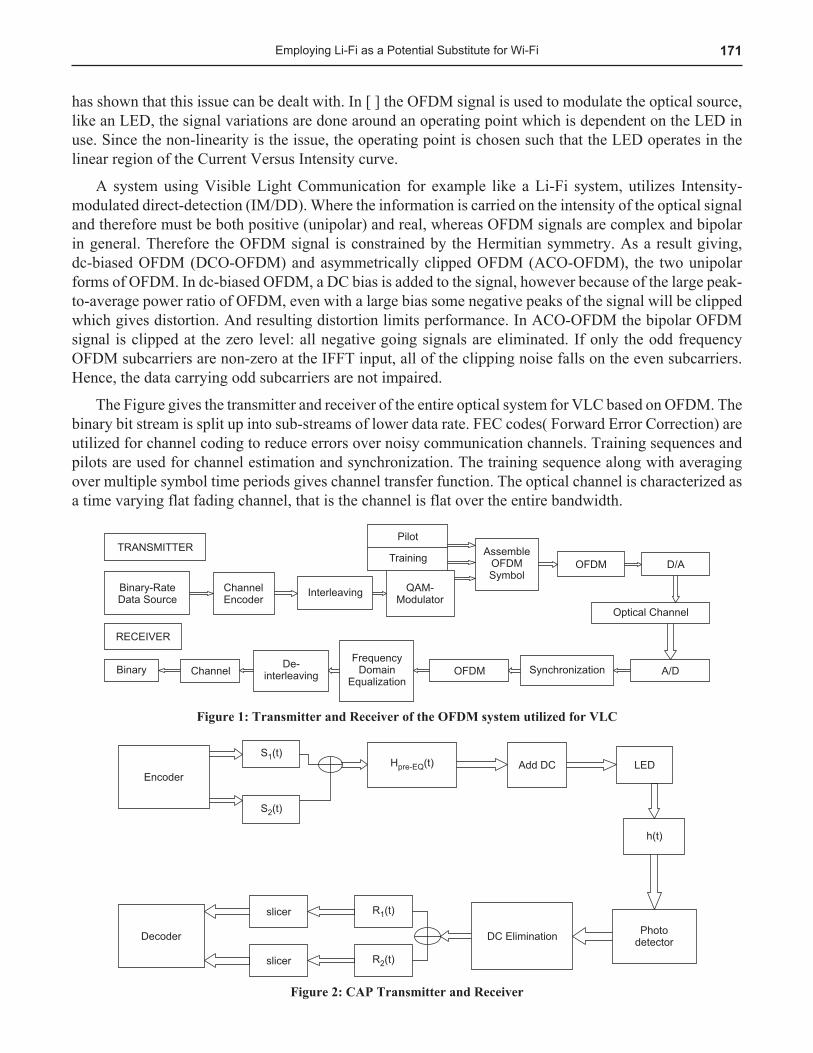
The Figure gives the transmitter and receiver of the entire optical system for VLC based on OFDM. The binary bit stream is split up into sub-streams of lower data rate. FEC codes( Forward Error Correction) are utilized for channel coding to reduce errors over noisy communication channels. Training sequences and pilots are used for channel estimation and synchronization. The training sequence along with averaging over multiple symbol time periods gives channel transfer function. The optical channel is characterized as a time varying flat fading channel, that is the channel is flat over the entire bandwidth.
Figure 1: Transmitter and Receiver of the OFDM system utilized for VLC
Figure 2: CAP Transmitter and Receiver
172 Nooguri Kavya, Sunayana Baruah, Duggirala Aishwarya, Mrudula Mahadasyam and C.T. Manimegalai
4. CONCLUSIONLi-Fi is envisioned to fill a complementary role along with WiFi to offload traffic from the macro Base Stations. VLC could also help in enabling indoor as well as in improving city canyon navigation where GPS signaling is nonexistent or weak. Because the front-end hardware is simple it can play a significant role in enabling the Internet of Things and machine to-machine communications in general. Museums, hospitals, and underwater communications are few of the other possible areas that stand to benefit from the practical implementation of VLC include. Museums could exploit the already present light fixtures to not only illuminate the particular objects/subjects, but also continuously transmit information like history, background etc. about them. This could definitely redefine the way automated tours are executed. Hospitals could benefit from its ability for ubiquitous networking without any detriment to equipment that is sensitive to RF radiation. This should improve hospital care and reduce staff workload.
Underwater communications would probably benefit the most. RF and sound communication are unable to provide fast wireless connectivity under water. Although VLC is also likely to face challenges in that particular propagation environment, it has the potential to deliver significant data rate improvements when conditions allow.
Even as OFDM and CAP show characteristics of a promising candidate technology to enable Li-Fi, the question of combating nonlinearity in the LEDs is one of the biggest challenges for VLC systems. However, as technology unfolded through the years technical challenges in RF have been conquered. Hence with continued research VLC is well equipped to go along a similar but much accelerated path.
References1. By Lajos Hanzo, Fellow IEEE, Harald Haas, Member IEEE, Sándor Imre, Member IEEE, Dominic O’Brien, Member IEEE,
Markus Rupp, Senior Member IEEE, and Laszlo Gyongyosi, Member IEEE, “Wireless Myths, Realities, and Futures: From 3G/4G to Opticaland Quantum Wireless”, Manuscript received January 26, 2012; accepted February 7, 2012. Date of publication April 27, 2012; date of current version May 10, 2012.
2. H. Elgala, R. Mesleh, H. Haas and B. PricopeSchool of Engineering and ScienceInternationalUniversity Bremen28759 Bremen, Germany, “OFDM Visible Light Wireless Communication” Based on White LEDs,published in 2007.
3. Harald Burchardt, Nikola Serafimovski, Dobroslav Tsonev, Stefan Videv, and Harald Haas, “VLC: Beyond Point-to-Point Communication”, IEEE Communications Magazine, July 2014.
4. Mostafa Z. Afgani, Harald Haas, Hany Elgala, and Dietmar KnippSchool of Engineering and ScienceInternational University Bremen28759 Bremen, Germany, “Visible Light Communication Using OFDM”, published 2006 IEEE.
5. Hyunchae Chun, Pavlos Manousiadis, Sujan Rajbhandari, Member, IEEE, Dimali A. Vithanage, Grahame Faulkner, Dobroslav Tsonev, Jonathan James Donald McKendry, Member, IEEE, Stefan Videv, Enyuan Xie, Erdan Gu, Martin D. Dawson, Fellow, IEEE, Harald Haas, Member, IEEE, Graham A. Turnbull, Senior Member, IEEE, Ifor D. W. Samuel, and Dominic C. O’Brien, Member, IEEE, “Visible Light Communication Using a Blue GaNμLED and Fluorescent Polymer Color Converter”, published 2014IEEE
6. Jean Armstrong, Senior Member, IEEE, “OFDM for Optical Communications”, published 2009 IEEE.7. Shengchao Lin1, Jun-Bo Wang1, Jin-Yuan Wang1, Jiangzhou Wang2, Ming Chen1, University of Kent, UK, “Low-
timing-sensitivity waveform design for carrierless amplitude and phase modulation in visible light communications”, IET Optoelectron., 2015, Vol. 9, Iss. 6, pp. 317–324.