Emittance Reduction between EBIS LINAC and Booster by Electron
19
BNL-8 1584-2008-IR C-NAP/#303 April 2008 Emittance Reduction between EBIS LINAC and Booster by Electron Beam Cooling; Is Single Pass Cooling Possible? Ady Hershcovitch Collider-Accelerator Department Brookhaven National Laboratory Upton, NY 11973 Notice: This document has been authorized by employees of Brookhaven Science Associates, LLC under Contract No. DE-ACO2-98CH10886 with the U.S. Department of Energy. The United States Governmentretains a non-exclusive, paid-up, irrevocable, world-wide license to publish or reproduce the published form of this document, or allow others to do so, for United States Government purposes.
Transcript of Emittance Reduction between EBIS LINAC and Booster by Electron
BNL-8 1584-2008-IR
C-NAP/#303 April 2008
Emittance Reduction between EBIS LINAC and Booster by Electron Beam Cooling;
Is Single Pass Cooling Possible?
Ady Hershcovitch
Collider-Accelerator Department Brookhaven National Laboratory
Upton, NY 11973
Notice: This document has been authorized by employees of Brookhaven Science Associates, LLC under Contract No. DE-ACO2-98CH10886 with the U.S. Department of Energy. The United States Government retains a non-exclusive, paid-up, irrevocable, world-wide license to publish or reproduce the published form of this document, or allow others to do so, for United States Government purposes.

Emittance Reduction between EBIS LINAC and Booster by Electron Beam Cooling; Is Single Pass Cooling Possible?
Ady Hershcovitch
Electron beam cooling is examined as an option to reduce momentum of gold ions exiting the EBIS LINAC before injection into the booster. Electron beam parameters are based on experimental data (obtained at BNL) of electron beams extracted from a plasma cathode. Preliminary calculations indicate that single pass cooling is feasible; momentum spread can be reduced by more than an order of magnitude in less than one meter.
I. Introduction
It has been know for quite some tome that low thermal spread electron beam moving at the same velocity with a hotter charged particle beam has a cooling effect on that beam. Experimentally, electron beam cooling of ions has been successfully performed in a number of storage rings.
Plans are to replace the Tandem van de Graaff accelerator RHIC preinjector with an EBIS' ion source, which is followed by a radiofrequency quadrupole (RFQ) LINAC and an interdigital-H LINAC. Although EBIS is expected to have some significant advantages over the presently operating Tandems, ion beam emittance at the end of the EBIS-RFQ-LINAC system is estimated to be much larger than the ion beam emittance at the end of the second van de Graaff. Momentum spread at the end of the LINAC is expected to be = 1 0-3, where p is momentum.
In this note, a simple electron cooling method for reducing the above momentum spread by over an order of magnitude is explored. A previously generated steady state intense low emittance electron beam could be used for a single-pass cooling of the ion beam end of the EBIS-RFQ-LINAC system, though other electron guns might be suitable as well.
11. Basic Considerations; Is It Worth Pursuing?
Expected ion beam parameters2, based on design, at the exit of the EBIS-RFQ-LINAC system are: energy 2 MeV/u, momentum spread*p , beam diameter 1 cm, and
gold ion charge state Au '~~, with ion density2 at the LINAC exit ni=8x10⁷ cmm3. For electrons to match ion velocity, their energy U must be about 1 KeV. At these energies, ion and electron velocities are about 2x10⁷ meter/second, hence p = 0.0667 and y = 1.0022.
= L
In this basic consideration an electron gun with plasma cathode, from which 9 A were extracted at 1 KeV through a 6 mm aperture3, is considered. Based on these parameters the electron density n can be computed from n = gev , where I is electron beam
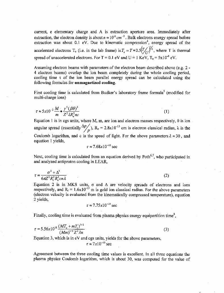
current, e elementary charge and A is extraction aperture area. Immediately after extraction, the electron density is about n = 10" . Balk electrons energy spread before extraction was about 0.1 eV. Due to kinematic compression4, energy spread of the
accelerated electrons T, (Le. in the lab frame) is T, = T * 0.5(@, where T is thermal spread of unaccelerated electrons. For T = 0.1 eV and U = 1 KeV, T, = 5x1 0-4 eV.
Assuming electron beams with parameters of the electron beam described above (e.g. 2 - 4 electron beams) overlap the ion beam completely during the whole cooling period, cooling time z of the ion beam parallel energy spread can be calculated using the following formulas for unmagnetized cooling.
First cooling time is calculated from Budker's laboratory frame formula5 (modified for multi-charge ions)
Equation 1 is in cgs units, where M, m, are ion and electron masses respectively, 0 is ion angular spread (essentially ), = 2.8~10- l~ cm is electron classical radius, h is the
Coulomb logarithm, and c is the speed of light. For the above parametersa = 30 , and equation 1 yields,
z = 7.68~10-'~ sec
Next, cooling time is calculated from an equation derived by P ~ t h ~ ~ ~ , who participated in and analyzed antiproton cooling in LEAR,
o3 +A3 6nZ2 R; R;cnA
z=
Equation 2 is in MKS units, (r and A are velocity spreads of electrons and ions respectively, and Ri = 1 .6~10- l~ m is gold ion classical radius. For the above parameters (electron velocity is evaluated from the kinematically compressed temperature), equation 2 yields,
z = 7.75xlO-'' sec
Finally, cooling time is evaluated from plasma physics energy equipartition time',
(MT, + mq)3'2 (Mm)"2Z2;tn
z = 5.56~10" (3)
Equation 3, which is in eV and cgs units, yields for the above parameters, z = 7x1 0-l' sec
Agreement between the three cooling time values is excellent. In all three equations the plasma physics Coulomb logarithm, which is about 30, was computed for the value of

parallel electron temperature. Ion velocity spread was computed from ion temperature, i.e. thermal velocity spread is used.
Since ion and electron velocities are about 2x10⁷ meterhecond, substantial cooling in the parallel direction can be accomplished in about 1.5 cm. hence, the answer to whether pass cooling seems is worth pursuing is affirmative. However, in the perpendicular direction, the electron temperature is not compressed, hence, cooling in that direction is not very effective, and the Coulomb logarithm will be 3.4, resulting in micro-seconds cooling time. Therefore magnetized cooling is needed. More importantly, magnetic field is needed to confine the electron beam to prevent an otherwise very rapid expansion. As it is shown in the next section, in realty the cooling time is larger by an order of magnitude.
111. Magnetized Cooling
Cooling time values computed in the previous section are for cooling in the direction parallel to beam propagation. In absence of a magnetic field, cooling in the perpendicular direction does not benefit fiom kinematic compression of accelerated beams. Hence, uncompressed value of the electron beam velocity spread must be used (and a somewhat different cooling force expression). The result is that cooling time in the perpendicular direction will be of the order ofz x 5.6~10" sec , i.e. orders of magnitude higher. Electron beam cooling under this scenario is unlikely to be feasible this application, since 112 meters are needed for cooling.
IIIa Formulas
Magnetized Cooling Calculations Based on Currently Used Friction Force
In case of a magnetic field, which sufficiently strong such that at large impact parameters electron-ion collisions are adiabatic with respect to electron Larmour rotation, the electron transverse degree of freedom no longer factors in the kinetics of collisions. Under such conditions, electron beam cooling efficiency is determined by the longitudinal electron thermal spread, which is orders of magnitude smaller than the transverse spread.
Theoretical magnetized friction force in the parallel 4, and perpendicular F' directions in cgs units is given by9
and 2 n e 4 ~ 2 n ~ 24' FL = 0
M (5)
where subscripts 1 1 and I refer to friction forces and to velocity spreads in the parallel and normal directions.

Cooling rate, which is proportional to ion energy E loss rate to electrons, is defined aslo
-=F.V.Hence, z=- dt F dE MV,
Substituting for F in equation 6 from equations 4 and 5, expressions for cooling times are obtained. It should be pointed out that there is a derivation" predicting friction forces lower by a factor of two. But, Ogino and Ruggiero12 and Smenson and Bonder~p '~ reach results that are essentially the same as equations 4 and using different approaches.
Nevertheless, Parkhomchuk" claims that an empirical formula is in much better agreement with computer simulations of fully magnetized cooling for magnetic fields of up to 4kG. Additionally, experiment^'^ and computer sim~lations'~ showed reasonable agreement with Parkhomchuk". Even though in this case magnetic fields are much larger and the assumption of absolute magnetization is most likely valid, Parkhomchuk' s empirical formula should be used16. In this case, increase in electron beam thermal spread due to space charge17 is still lower than ion thermal spread16 (a simple estimate of the
cgs units yields an energy spread of 6 .68~10-~ eV, which is orders of magnitude lower than the ion beam thermal spread).
electron beam thermal spread due to the electrostatic space charge potential 17 e 2 n 1/3 in
Magnetized friction force and cooling time based on the empirical formula", in cgs units, are
4z2e4nil F = vi
and r=--.k- Mv. Mv,mvi,
mvii
- F 4Z2e4nilvi
(7)
where Vi and V h i are ion beam velocity and ion thermal spread respectively. The appropriate Coulomb logarithm in this case is
where a p e and Pe are electron plasma frequency and gyro-radius respectively. For these parameters
h = 2.77 and z = 1.25~1 0-' sec
In equations 7 and 8 thermal velocity spread is used, Le. ion velocity spread was computed from ion temperature. Basically, ions distribution is assumed be to be a beam with thermal spread (three degrees of freedom). Velocity spread computed directly from the momentum spread will be larger by a factor of 42, for which
h = 3.14 and z = 3.35xlO-'sec

More important, equations 4 and 5 were derived under the assumption of full magnetization. If the magnetic field is not high enough, adiabaticity condition for low impact parameters collisions can be violated, in which case friction forces must be computed (and added up) for two ranges of impact parameters. Scaling up from previously analyzed cases17, maximum cooling decrement can be reached for magnetic fields of/or exceeding 2.4 T, which is the magnetic field of choice. Based on the worse case computed from equations 8 and 9, a cooling length of 67 cm is needed, or 25 cm in the other case.
Since the ion beam density (of ni=8x10⁷ ~ m - ~ ) is orders of magnitude lower than the electron density ofn = 1011cm-3 , cooling the ions will have negligible effect on the equilibrium electron temperature. Therefore under unmagnetized full thermal equilibrium, parallel ion temperature will be reduced to the electron temperature. But in a magnetized case the process is more complex due to freedom of motion restrictions imposed by the magnetic field.
Transverse thermal equilibrium T,, is given by17
in cgs units, where 70 is time an ion spends in the electron beam, cope and Re are electron plasma and cyclotron frequencies respectively. For a magnetic field of 2.4 Tesla, and zo of sec, the perpendicular ion energy spread is reduced to 1.88 eV, and the transverse momentum spread to
Basically, the transverse momentum spread, and hence ion beam emittance, can be reduced by over an order of magnitude. And, the parallel momentum spread will be reduced by a similar factor.
IIIb Ion Heating
Since the ion beam density (of ni=8x10⁷ ~ m - ~ ) is low, intra beam scattering (IBS) is insignificant during this cooling process. But, the electron density (of n = IO" cm-3 ) is many orders of magnitude higher than the ion density. Therefore, interactions with electrons dominate velocity space diffusion (relaxation). In this case the use of plasma physics formulas is fully justified to compute ion velocity space diffusion for the following reasons.
Given ion and electron beam parameters, the Debye length h~=7.43x10-~ cm, hence there are about 1346 Debye lengths in a beam diameter. And, there are about 182 electrons in a Debye sphere. Electron gyro-radius is 3 .13~10-~ cm. Hence, there are almost 32,000 electron gyro-radii in a beam diameter. Electron gyro-frequency is 6 . 7 2 ~ 1 0 ' ~ Hz in this magnetic field of 2.4 Tesla. During an interaction time (computed above) of z = 3 . 3 5 ~ 1 0 ~ ~ sec, an electron completes 2251 gyrations. No past, existing, or future

(planned) electron beam cooler has parameters where beam diameter to gyro-radius and Debye length ratios, as well as the number of electron gyrations are such large numbers. Therefore, classical plasma physics formalism is fully justified in this analysis. In this magnetic field ion gyro-frequency is about 6 MHz, i.e. ion gyration period is over a factor of 5 larger than the longest interaction (cooling) time. So ions are not magnetized.
Ion inter-particle distance is 2 . 3 ~ 1 0 - ~ cm, i.e. larger than 3 Debye lengths. Therefore, ions are totally shielded from each other. Hence, their interaction is solely with electrons. Therefore, the test particle model, in which relaxation rates of test particles steaming through a background of field particles are computed, is particularly suitable in this application. Furthermore, relaxation rates for a single ion (test particle), whose energy equals ion beam thermal spread, streaming through cooling electrons (field particles), are a reasonable approximation of the ion beam velocity space relaxation rates. Norman Ro~toker '~ ' '~ originated the test particle model, which for a Maxwellian of field particle distribution, exact formulas2' were derived; and, expressions exis?' for cases where test particle energy is much smaller or much larger than field particle energy. Magnetic field effects'8y22 are accounted for through the Coulomb logarithm. Furthermore, the test particle model has been verified23 experimentally.
For simplicity, computations are performed in the beam rest frame, since y = 1.0022, corrections to time dilations are minuscule. Pertinent relaxation rates vi'e in sec-' (ion test particle in a background of field electrons) are defined in the following equations
d - ile- -v. =-v, vi dt
dt
dt
- d - - 2 i le 2 -(vi - vi)l = v, vi
--(vi -vi)ll = VII vi 4 d - - 2 i le 2
Subscripts (s, I,& I I) denote slowing down, transverse diffusion in velocity space and parallel diffusion in velocity space respectively. Relaxation times can be determined from
Mvi2 2kTe
the relaxation rates, which for - = 4000 >> 1, can be found2' to be
Units are cgs and eV. T, is 0.1 eV, p ion to proton mass ratio. Since electron are magnetized, the Coulomb (b is the smallest impact parameter) is
A=ln - ~ 3 . 2 (16) (3 From equations 14, 15 and 16 relaxation times are, for a 394 eV ion (corresponding to the thermal energy spread),
zl, = = 40x1 0-6 sec, and zl c Aye = 3x10⁹ sec (17)

Equations 17 yield velocity space diffusion relaxation times that are orders of magnitude longer than the computed cooling times. Computing ion cooling time based on ion slowing down time2’ (a.k.a. dynamic friction), v;le = 1.7~10 p nZ2h”/* and z, = z, fi: x:,e z 1 ~ 1 0 - ~ sec
Equation 18 yields a cooling time, which is in very good agreement with Parkhomchuk’s empirical formula.
(18) -4 112
IIIc Coulomb Logarithm
In classical plasma physics the Coulomb logarithm is defined as the ration of largest to smallest deflection angle (can be found in many basic plasma books like reference 24 for example). The largest possible deflection (1 80’ scattering) is produced by the smallest impact parameter, which is basically the ratio of electrical potential energy to particle kinetic energy, i.e. how close can two particles be. The largest impact parameter is of course the Debye shielding length. It all works very for infinite homogenous unmagnetized plasmas with isotropic temperature. But as it can be seen from section 11, deviation from these conditions can lead to unrealistic results.
To be consistent with classical Boltzmann theory, the largest impact parameter is taken to belsJ2 the electron gyro-radius. Parkhomchuk’s empirical formula” also sets the electron gyro-radius as the largest impact parameter. Nevertheless, the electron gyro-radius should not be set as the largest impact parameter in a cavalier way in any magnetized plasma. In cold, high-density plasmas in low to moderate magnetic fields, Debye lengths can be shorter than electron gyro-radii. Hence the Debye length must be set as the largest impact parameter. In this case the Debye length is 1~=7.43xlO-~ cm, which is much longer than the electron gyro-radius of 3 . 1 3 ~ 1 0 ~ ~ cm. Therefore, setting the electron gyro-radius as the largest impact parameter is fully justified in this analyzed case.
IV. Pertinent Physics Issues
A number of pertinent physics issues are evaluated next. First topic is maintaining electron beam parameters. Second subject matter is adverse effects the electron beam (or electron gun) might have on the gold ions. Third topic is whether electron gun generated gas is tolerable.
IVa Magnetic Field Required for Electron Beam Equilibrium and Stability
As it is shown in the next section, current density of the extracted electron beam exceeds the Child Langmuir law limit. Hence, rapid expansion of the electron beam occurs, unless the expansion is prevented by a magnetic field. For a square electron density profile, the electric field E, at the outer beam radius R is given in m k s units by
(19)

Neglecting kinetic pressure (will be become obvious a posteriori that the assumption is correct), to contain the electron beam, magnetic pressure must balance pressure generated by the electric field. Hence the needed magnetic field B can be found from24
From equation 19, the electric field E,=2.7x10⁶ V/m. Therefore from equation 20 a magnetic field of about 90 Gauss is sufficient to contain the electron beam. Since the electron beam is space charge dominated, thermal spread contributions to its pressure are negligible. A more stringent magnetic field requirement is imposed by plasma stability, which necessitates a magnetic field that satisfies2'
(21) w" p " < 1 n; -
Equation 21 yields a minimal magnetic field requirement of about 2x10³ Gauss or 0.2 Tesla. These magnetic fields are small compared to the 2.4 Tesla magnetic field, which maximizes the cooling decrement. Hence electron beam confinement and stability is not an issue.
At a magnetic field of 2.4 Tesla, electron gyro-frequency is 6.72~10" Hz. Therefore, electrons complete over 2251 gyrations in 33.35 nsec. Hence, beam electrons are magnetized during the ion cooling process.
IVb Ion Loss Due to Recombination
Due to interactions with beam electrons ion inelastic interactions are: electron capture and ionization. But due to the relative low energy differential, the only ion loss
for electron mechanism is due to recombination, which was studied extensively coolers. Rate coefficient for recombination a is26
26,27,28
* 27,28 from which reaction rate can be computed and ion lifetime T~~~ is
Equations 22 and 23 are in cgs units except for T, which is in eV. The assumption in deriving equation 22 that T,, >> T,,, is valid for our case too (all is done is laboratory frame). For our parameters aree is about 1.5 msec, which is orders of magnitude longer than any computed cooling time. Additionally, electron capture is suppressed in such a large magnetic field. Hence, electron recombination is not an issue in this process.
Other channels of recombination like three body collisional recombination or dielectronic recombination have extremely low probability6. Cross ~ e c t i o n ~ ~ ' ~ ' for the latter, for example, is usually of the order of cm2 or less. The low cross sections combined with 10's nsec interaction time and a mean free path of lo8 cm render these processes unimportant.

IVc Charge Exchange
One of the electron guns that is being considered is hollow cathode plasma cathode3 (to be described in the next section; relevance of this paragraph will become apparent in the next section). Pressure in the electron gun3 is about Torr of argon gas. High charge exchange cross sections are usually of the order of cm2, for which the mean ftee path is 336 cm. However, inside the hollow cathode the pressure is about Torr. In this pressure the mean free path is less than 0.3 cm. Therefore, ion beam injection through the hollow cathode in current embodiment is not an option. In the electron gun extractor background gas pressure is under Torr; hence the mean free path is a longer than 400 cm. Outside the extractor pressure is Torr, where charge exchange is no longer an issue.
A more suitable electron gun could be an electron gun with carbon fiber cathode3’, which have generated close to 1 MA of electron current. More recently32 currents of up to 2 kA at 2 kV were obtained in microseconds long pulses. Depending on the current generated, pressure during the electron beam pulse can be between Torr (or even lower where large pumping capability is available). Since the needed electron beam currents are well below 100 A, pressures below Torr, where charge exchange is not an issue, are expected.
to
IVd Other Plasma Instabilities
Based on equation 21, the electron beam should be stable for an axial magnetic field of 2.4 Tesla. If the electron beam is stable, there should, in principle, be no other instabilities. The only possible plasma instability might be to the ions (like a rotating two stream instability). Like all beam instabilities, it has a density threshold. Since the ion density is more than three orders of magnitude lower than the electron density, there should be no beam instabilities.
V. Electron Gun Options
Three electron gun options are examined: electron guns with plasma cathodes, electron guns having conventional solid cathodes with staggered, staged acceleration, and electron guns with carbon fibers or nano-tubes cathodes.
Va Plasma Cathode
During the late 1980’s till the mid 1990’s a novel electron gun with a plasma cathode was developed at BNL3,33,34. Since plasma cathodes are easier to fabricate and are more efficient than thermionic sources, these cathodes were viewed as potential alternatives to thermionic cathodes about thirty years ago. However, present day plasma cathodes have some serious shortcomings. Consequently, plasma cathodes have only a few limited applications although considerable research interest remains.
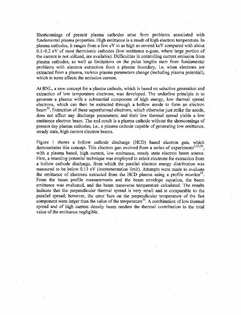
Shortcomings of present plasma cathodes arise from problems associated with fundamental plasma properties. High emittance is a result of high electron temperature. In plasma cathodes, it ranges from a few eV to as high as several keV compared with about 0.1-0.2 eV of most thermionic cathodes (low emittance e-guns, where large portion of the current is not utilized, are available). Difficulties in controlling current emission from plasma cathodes, as well as limitations on the pulse lengths stem from fundamental problems with electron extraction from a plasma boundary, Le. when electrons are extracted from a plasma, various plasma parameters change (including plasma potential), which in turns affects the emission current.
At BNL, a new concept for a plasma cathode, which is based on selective generation and extraction of low temperature electrons, was developed. The underline principle is to generate a plasma with a substantial component of high energy, low thermal spread electrons, which can then be extracted through a hollow anode to form an electron beam33. Extraction of these superthermal electrons, which otherwise just strike the anode, does not affect any discharge parameters; and their low thermal spread yields a low emittance electron beam. The end result is a plasma cathode without the shortcomings of present day plasma cathodes, i.e., a plasma cathode capable of generating low emittance, steady state, high current electron beams.
Figure 1 shows a hollow cathode discharge (HCD) based electron gun, which
with a plasma based, high current, low emittance, steady state electron beam source. First, a retarding potential technique was employed to select electrons for extraction from a hollow cathode discharge, from which the parallel electron energy distribution was measured to be below 0.13 eV (instrumentation limit). Attempts were made to evaluate the emittance of electrons extracted from the HCD plasma using a profile monitor35. From the beam profile measurements and the beam envelope equation, the beam emittance was evaluated, and the beam transverse temperature calculated. The results indicate that the perpendicular thermal spread is very small and is comparable to the parallel spread; however, the error bars on the perpendicular temperature of the fast component were larger than the value of the temperat~re~~. A combination of low thermal spread and of high current density beam renders the thermal contribution to the total value of the emittance negligible.
demonstrates this concept. This electron gun evolved from a series of experiments 3,33,34 ,

DC CURRENT TRANSFORMER PART OF SOURCE ENCLOSURE
INS U L4TO RS
Ta HOLLOW CATHODE
TO PUMP
EXTRACTOR
ELECTRON REP. GRIDJ
0 1 U cm
\,€Ah4 DUMP
Figure 1 only gun drawn to scale. Electron repelling grid selects low emittance electrons for extraction.
From these measurements, it was shown that at conventional operating pressures, the parallel (to the direction of extraction) electron energy distribution function is Gaussian- like with a superthermal tail. At low operating pressures (of 1 . 8 ~ 1 0 - ~ Torr or below), the central core of the external HCD plasma is characterized by two electron populations: bulk electrons having a thermal spread of several eV and a population of fast electrons with a very narrow energy spread. This additional distinct component of electrons has an energy corresponding to the cathode potential and a very low spread of 0.13 eV. A negatively biased grid (to a potential whose magnitude is slightly lower than the energy of the fast electrons) is used to repel the bulk electrons and EXB filter can be used to separate the fast electrons from the tail of the distribution function.
Basically an electron gun, based on extraction of superthermal electrons from a discharge characterized by a large component of high energy electrons with a low thermal spread, was demonstrated. Hollow cathode diameter was 3 mm. A grid is employed to select these electrons for extraction while retaining the bulk electrons in the discharge. Steady state extraction of electron beams corresponding to over 60% of the total arc discharge current has been observed. This extracted electron current far exceeds the thermal electron flux. A perveance of over 280 microperv was reached with the extraction of 9 A at 1 keV from a 6 mm extractor aperture. This electron gun concept can be the basis of an electron gun system for such an e-beam cooler.
Given the sizes of the ion and electron beams, it is obvious that for complete overlap, the electron beam diameter must be either scaled up to the size of the ion beam, or a few (2 -

4) electron beams are to be used. Inch size (and larger) hollow cathodes generating hollow cathodes arc have been operational in numerous laboratories. Therefore, one approach could be to reproduce the old electron gun results with a larger cathode. Other option is to merge electron beams from multiple HCD based electron gun.
An attractive feature of the HCD based electron gun is the hollow nature of its solid structure. However gas and/or plasma can adversely affect the ion beam due to charge exchange. Therefore, next topic to consider is whether a concentric system (ions injected through the electron gun), or external electron injection into the ion path is the more realistic option. To overcome the gas and plasma of the concentric system, a large electron gun with concentric cathodes as shown in figure 2 can be developed, based on reference 36 system. In that configuration, gas and plasma are only between the inner and outer hollow cathodes. Such a system is in principle possible, but the devil is in the
Figure 2 not to scale. Plasma exists only between inner and outer cathodes; negligible amounts of gas in ion beam path.
In the HCD based plasma cathode, electron current flows through plasma, where it is neutralized. The grid, which repels the bulk electrons, sends ions into the extraction, where a virtual cathode is probable formed. Therefore, the effective extraction gap is smaller than its solid dimensions. Another factor for the enhanced extracted current density is that the extracted electrons have some energy, which enhances the space charge limit. The reason that neither an electron gun with staggered, staged acceleration, nor HCD based plasma cathode electron guns have found use is that the electron beam blows up after extraction. When the Child Langmuir law is (or any law of nature) violated, there

is a price to be paid. In this case, however, the electron beam is in a large magnetic field, which prevents its rapid expansion.
Vb Conventional Thermionic Cathodes
Solid cathodes have a clear advantage in that they do not have the gas and plasma issues associated with plasma cathodes. Hence a concentric configuration seems easier to implement, since no differential pumping is needed. However based on current technology, R&D is still needed. Current density j (in A/cm2) extracted from these cathodes is limited to the Child Langmuir law, which is given by,
j = 2.33~10-~ - , where V is extraction Voltage and d is extraction gap. Current
density extracted from the HCD based electron is close to 32 A/cm2. Hence for 1 kV extraction Voltage, extraction gap cannot exceed 0.048 cm. The Child Langmuir law derivation is based on extraction of electrons with no or negligible energy. If electrons have substantial initial velocity, extraction current density can be, in principle37, larger by more than two orders of magnitude. Over twelve years ago, the author started work on developing an electron gun, in which advantage of initial velocity is made to enhance extracted current density. Preliminary encouraging results, which were obtained with staggered, staged acceleration, showed that it possible to increase the extracted electron current density larger by a substantial factor. And ultimately, the enhancement can reach two orders of magnitude. But, substantial R&D is required to develop an electron gun with a solid cathode that will generate an electron beams with electron density of about n = lO"crn" with energy of 1 kV.
y 3 I 2
d2
Vc Carbon Fiber Cathodes
Very large current densities can be extracted from carbon fibers nano-tubes, laser electron guns. Pulsed electron guns, with these types of cathodes, have been built. Since each ion beam micro bunch is 10 nsec long at 100.62 MHz, pulse electron guns are a better option due to energy savings. Laser electron guns are complex, while electron guns based on carbon fibers or nano-tubes cathodes are much simpler and are characterized by extremely field high emission due to the very small size of the each emitting surface. Experience with cathodes made of 7 micron and 5 micron carbon fibers showed that current densities of lo5 A/cm2 can be extracted from each fiber. Currents of 50-200 kA were extracted3' fiom carbon fiber areas of 50-100 cm2. Ring-shaped cathodes32 with 1 mm thick annulus of 1 cm diameter generated currents of up to 2 kA at 2 kV in 10 - 15 microsecond long pulses.
Schematic of a cooling embodiment (very rough; not to scale) based on carbon fiber or nano-tubes cathodes is shown in figure 3. For testing cathode concepts, a similar electron gun structure can be fabricated for test both carbon fiber or nano-tubes cathodes as well as the concentric HCD plasma cathode displayed in figure 2, in which very effective differential pumping is possible.

Figure 3 electron gun based on carbon fiber or nano-tubes cathodes (not to scale).
VI. Possible Course of Action
Although the results of the above analysis are of a very preliminary nature, it will be prudent to design the section between the EBIS LINAC and the Booster in such a way that 150 cm after the LINAC could be modified to accommodate an electron beam cooler, since the RHIC EBIS is scheduled to become operational on a time scale shorter than any possible R&D. There are two basic design concepts that can be employed to accomplish this ion cooling.
Figure 4 shows an embodiment, where the electron beam is generated external to the ion beam. Such a setup is commonly used in existing and planned electron beam coolers. An existing electron gun or one like the HCD plasma cathode electron gun, which was developed at BNL, can be adopted with straightforward R&D. However beam-merging optics is none trivial at best. And the ion beam must be handled properly after cooling.
3,33,34
Figure 4 sketch of a cooling setup involving electron beam generated external to ion beam line.
A much better choice would to have the ion beam concentric with the electron gun for obvious reasons. Figure 5 is a rough sketch of the setup. Possible conceptual cathodes can be seen in figures 2 and 3. Nevertheless, the ion beam must be handled properly after cooling. On the other hand, more extensive electron gun R&D is required for this approach.
Figure 5 sketch of a cooling setup involving concentric electron and ion beams.
Before any significant endeavor is made, it is prudent to perform a proof-of-principle experiment regardless of which concept is to be pursued. Simultaneously additional analysis, as well as computer simulations should be performed.
Proof of principle testing can be performed with small radius ion beams from the Van De Graaff. Specifically, testing can be performed for adverse affects an intense electron beam might on an ion beam. Experimental details are beyond the scope of this note.
Once experimental proof is attained, electron gun development can commence. Based on which electron gun shows promise, electron beam cooling setup choice can be finalized. Though a concentric system would be preferable.
VII. Discussion
Other than Parkhomchuk's empirical formula, which is used to calculate cooling rates, most computations in this note are based on plasma physics formalism. Given ion and electron beam parameters, the Debye length h ~ = 7 . 4 3 ~ 1 0 - ~ cm, hence there are about 1346 Debye lengths in a beam diameter. And, there are about 182 electrons in a Debye sphere. Electron gyro-radius is 3 .13~10-~ cm. Hence, there are almost 32,000 electron gyro-radii in a beam diameter. Electron gyro-frequency is 6.72~10" Hz in this magnetic field of 2.4 Tesla. During an interaction time (computed above) of z = 3.35xlO-' sec, an electron completes 2251 gyrations. In this magnetic field ion gyro- frequency is about 6 MHz, Le. ion gyration period is over a factor of 5 larger than the longest interaction (cooling) time. So ions are not magnetized. No past, existing, or future (planned) electron beam cooler has parameters where beam diameter to gyro-radius and Debye length ratios, as well as the number of electron gyrations are such large numbers. Furthermore, transport and velocity space relaxation theories based on the test particle model were proven to be correct e~perimentally~~ in a series of experiments performed on two different devices. Therefore, classical plasma physics formalism, especially when based on the test particle model, is fully justified in this analysis.
Answer to the question posed in the title, on whether single pass cooling is possible, is affirmative. While velocity relaxation and cooling computations, based on the test particle model, have had experimental verification, electron beam cooling theories did not agree with cooling experiments. Hence, the need for Parkhomchuk's empirical formula", which has shown to be in good agreement with ion cooling (slowing-down) computations (equations 11 and 18) that are based on the test particle model. Some discrepancies with theories used in conjunction with electron beam cooling may be due to the very different parameters of this case as compared to parameters in electron beam cooling. In equation 15, e.g. the electron beam temperature (instead of a delta function) must be included due to overlapping of ion and electron distributions in velocity space.
Further evaluation requires an iteration process, of simulations and of electron gun as well as electron beam cooler design, to further explore concepts presented in this note. Electron guns with carbon fiber cathodes should be able to achieve the needed electron beam parameters. Carbon nano-tubes might be superior, due to their extreme durability, which also eliminates any gas problems.
Based on cooling computations performed in sub-sections IIIa and IIIb, momentum spread of gold ion beams exiting the EBIS LINAC can be reduced by a factor of about 14 in a cooling distance of 20 cm (based on plasma physics formalism) to 25 cm or 67 cm (Parkhomchuk's empirical formula; depending on the value used for thermal spread).

Interesting physicsa regardless of the particular application! Motivation for this work is indeed cooling the EBIS LINAC ion beams before injection into the Booster. However, as initial calculations were performed it became apparent that there is a consensus in the electron beam cooling community that single pass cooling is impossible’6. If successful it will 1 st single pass cooling ever with implications far beyond this particular case.
References
1. http://www.bnl.govlcadlebis/ 2. Deepak Raparia, private communication (2008). 3. Ady Hershcovitch, APL 68,464 (1996). 4. S.L. Kauhan, Opt. Comm. 17,309 (1976) 5. G.I. Budker, Atomnaya Energia, 22,346 (1967).
7. H. Poth, et al., NIM A287,328 (1990). 8. B.A. Trubnikov, “Particle Interactions in a Fully Ionized Plasma,” Rev. of
Plasma Phys., 1 (Consultants Bureau, N.Y.) 105 (1965). 9. Ya.S. Derbenev and A.N. Skrinsky, Plasma Physics 4,492 (1978). 10. V.V. Parkhomchuk, NIM A 441,9 (2000). 1 1. V.V. Parkhomchuk, “Physics of Fast Electron Cooling”, Proceedings of
12. T. Ogino and A.G. Ruggiero, Particle Accelerators 10, 197 (1980). 13. A. H. Smenson and E. Bonderup, NIM 215,27 (1983). 14. A.V. Fedotov, B. Gilnander, V.N. Litvinenko, T. Lofnes, A. Sidorin, A. Smirnov
and A. Zieman, Physical Review E 73,066503 (2006). 15. A. V. Fedotov, D.L. Bruhwiler, A. Sidorin, D.T. Abell, I. Ben-Zvi, R. Busby, J.R.
Cary, and V.N. Litvinenko, Physical Review ST Accel. Beams 9,074401 (2006). 16. Alexei Fedotov private communications (2007 & 2008). 17. N.S. Dikansky, V.I. Kudelainen, V.A. Lebedev, I.N. Meshkov, V.V.
Parkhomchuk, A.A. Sery, A.N. Skrinsky, and B.N. Sukhina, “Ultimate Possibilities of Electron Cooling,” Institute of Nuclear Physics, Novosibirsk, USSR Report, Preprint 88-61 (1988).
18. N. Rostoker and M.N. Rosenbluth, Physics of Fluids 3, 1 (1960); N. Rostoker, Nuclear Fusion 1, 101 (1961).
19. N. Rostoker, Physics of Fluids 7,491 (1964). 20. B.A. Trubnikov, Reviews of Plasma Physics, Vol. 1, (Consultants Bureau, New
2 1. NRL Plasma Formulary, J. D. Huba, NRL/PU/6790-06-49 1 , revised 2006. 22. D. Montgomery, G. Joyce, and L. Turner, Physics of Fluids 17,2201 (1 974). 23. J. Bowles, R. McWilliams, and N. Rynn, Phys. Rev. Letters 68, 1144 (1992); J.
Bowles, R. McWilliams, and N. Rynn, Physics of Plasmas 1, 3418 (1994); J.J. Curry, F. Skiff, M. Sarfaty, and T.N. Good, Phys. Rev. Letters 74, 1767 (1995)
24. D.J. Rose and M. Clark, “Plasmas and Controlled Fusion”, MIT Press, Cambridge MA (1 96 1).
25. R.C. Davidson, “Theory of Nonneutral Plasmas”, W.A. Benjamin, Inc. Advanced Book Program, Reading MA (1 974).
6 . H. Poth, CERN-EPI90-04.
Workshop on Electron Cooling and Related Applications” Karlsruhe, 1 884.
York, 1965), pp. 105-204.

26. M. Bell and J.S. Bell, Particle Accelerator 12,49 (1982). 27. A. Wolf et al. NIMA 441, 183 (2000). 28. V.V. Parkhomchuk, “(Electron Cooling for RHIC),” Budker INP, Novosibirsk,
Russia (2000) unpublished report. 29. P.F. Dittner, Phys. Scr. T22,65 (1988). 30. Y. Hahn, and K.J. LaGattuta, Phys. Rep. 166,195 (1988). 3 1. R. Prohaska and A. Fisher, Rev. of Sci. Instrum. 53,1092 (1982). 32. A. Hershcovitch, B. Johnson, F. Liu, A. Anders, I. Brown, Rev. of Sci. Instrum.
33. A. I. Hershcovitch, V. J. Kovarik, and K. Prelec, J. Appl. Phys. 67,671 (1990). 34. A. Hershcovitch, J. Appl. Phys. 74,728 (1993). 35. A. Hershcovitch, “Proceedings of the Fifth International EBIS Symposium ”,
edited by E. D. Donets and I. P. Yudin (JINR, Dubna, EBIS-5, Russia, 1991). 36. V.J. Kovarik, A.I. Hershcovitch, and K. Prelec, Rev. Sci. Instrum. 53, 819 (1982). 37. S. Humphries Jr., “Charged Particle Beams”, John Wiley and Sons Inc., New
69,798 (1998).
York (1990).
Acknowledgement
Very helpful discussions with Deepak Raparia, Ilan Ben-Zvi, Brant Johnson, Norman Rostoker and Roger McWilliams are gratefully acknowledged. Many thanks to Alexei Fedotov for numerous stimulating and extremely helpful discussions!
Notice: This manuscript has been authored by Brookhaven Science Associates, LLC under Contract No. DE-AC02-98CHl-886 with the US Department of Energy. The Untied States Government retains, and the publisher, by accepting the article for publication, acknowledges, a world-wide license to publish or reproduce the published form of this manuscript, or others to do so, for the United States Government purposes.