
EMI/RFI Shielding Products - RFMW Ltd, RFMW Shielding Products “MAJR Difference MAJR...
76
EMI/RFI Shielding Products “MAJR Difference MAJR Satisfaction” SHIELDING • GASKETING • VENTILATION PANELS • BOARD LEVEL SHIELDS FERRITES • CONDUCTIVE ELASTOMERS • THERMAL MATERIALS • EMI WINDOWS U.S. SBA – Certified Veteran Owned Small Business ITAR Registered RoHS Compliant C u s t o m B u i l t P r o d u c t s & P r o t o t y p e s I S O 9 0 0 1 : 2 0 0 8 R e g i s t e r e d
Transcript of EMI/RFI Shielding Products - RFMW Ltd, RFMW Shielding Products “MAJR Difference MAJR...

EMI/RFI Shielding Products“MAJR Difference MAJR Satisfaction”
SHIELDING • GASKETING • VENTILATION PANELS • BOARD LEVEL SHIELDS
FERRITES • CONDUCTIVE ELASTOMERS • THERMAL MATERIALS • EMI WINDOWS
U.S. SBA – Certified
Veteran Owned
Small Business
ITAR Registered
RoHS Compliant
Cust
om B
uilt P
roduct
s & Prototypes
ISO
900
1:20
08 R
egis
tere
d
is an internationally recognized manufacturer of
Electromagnetic Interference/
Radio Frequency Interference (EMI/RFI) Shielding Products.
We serve the electronics industry, specifically, telecommunications,
aerospace, computers, medical devices, instrumentation,
commercial electronics, government and military.
Our product line primarily consists of gaskets, elastomers,
EMI windows, board level shields, and air ventilation/filtration panels.
These products reduce or eliminate EMI/RFI “noise”
associated with electronics and are usually installed in or on the
enclosure or cabinet that contains the working electronics.
The electronics may be as small as a hand-held telephone,
or as large as a satellite communications array.
Our manufacturing facility is capable of
prototype to long-running production.
Always striving to exceed our customers’ expectations,
we provide prototyping, customizing, and flexibility
in scheduling in addition to quality products.
Data herein is believed to be correct and current. It has been checked for accuracy. No warranty, either expressed or implied, is made as to either its applicability to, or its compatibility with, specific requirements, nor for damages consequent to its use. All design characteristics, specifications, tolerances and similar information are subject to change without notice. Publication of this information is not intended to convey patent, copyright or any other intellectual property rights.
Contact us today to find how prompt, courteous service and fast turnaround will make
the “MAJR” difference in your product requirements.
17540 State Highway 198Saegertown, PA 16433
(814) 763-3211(877) MAJR PRO Toll Free
(877-625-7776)(814) 763-2952 Fax
(888) 763-2952 Toll Free Fax
Web address: www.majr.come-mail: [email protected]
Quality Policy and Mission Statement
MAJR Products provides product and technical service assistance
that meets customer requirements and strives to exceed customer
expectations. We are committed to continually improve our company by evaluating the
process of the quality management system. Our Mission and Values are:
• Enjoy your work
• Build trust by being ethical and honest with vendors, customers, and each other
• Encourage new product ideas and manufacturing improvements
• Update employees on the status and direction of the company
ISO 9001:2008 Registered
MAJR Products Corporation achieved registration to the ISO 9001:2008 standard during the second quarter of 2005.
Veteran Owned Small Business
MAJR Products Corporation is qualified as a Veteran Owned small business per the guidelines set up
and administrated by the Small Business Administration (SBA). The intent here is to help those that have
served our nation as they come back and start and operate their own businesses. Prime contractors
also receive benefits from the Federal Government for hitting certain quotas of business distributed to
Veteran Owned operations. We welcome requests for quotes from purchasing agents and procurement
officers looking to place business with a Veteran Owned company.
ITAR Registered
MAJR Products Corporation is an ITAR registered company.
Please call us direct if you need our registration number.
RoHS Compliant
MAJR Products Corporation is in compliance with the directives of WEEE and the
European RoHS Directive 2002/95/EC as the following substances banned in these directives
are excluded from our products: Cadmium, Hexavalent Chromium, Lead, Mercury, PBBs
and PBDEs. A certificate can be sent upon your written request.
BENEFITS OF DOING BUSINESS WITH
ORDERING, TERMS, MINIMUMS & OUR PART NUMBERING SYSTEM
This page will assist you in requesting quotes and ordering from MAJR Products Corporation. The basics of our quoting, ordering, minimums, terms and part numbering policies should be helpful to you in using this catalog to your advantage. As always we welcome any questions you may have regarding these policies.
• Quotes - MAJR Products goal is to turn around a quote on price and delivery to each and every customer within a 48 hour period. In order for us to do this we need all the pertinent information, part number, competitive part number to cross and it is always best if a complete drawing can be provided. This process can take longer for non-standard materials and highly complicated parts.
• Minimums - MAJR’s minimum purchase order is based on a set dollar amount. We also set a line item minimum within that con-text. Phone or email us for the minimum purchase order amount. These are set across standard part numbers but can vary on custom parts based on minimum purchases that MAJR could incur on exotic or unusual materials or processes.
• Ordering - All orders to MAJR must be in writing via mail, e-mail or fax. All purchase orders are reviewed per our ISO procedure and checked against quotes or recent orders completed for accuracy in pricing, delivery time, special shipping instructions or conditions, etc. Discrepancies result in immediate phone calls to the customer to be resolved. Once the correct amended PO is received and passes the customer will receive an acknowledgement, usually within a few days of the acceptance of the PO.
• Terms and Conditions – All orders are net 30 day payment terms unless otherwise agreed upon in writing with the customer. All shipments are FOB: Saegertown, PA 16433. MAJR Products reserves the right to alter the specifications provided in this publication. Consult factory for current specifications.
• Warranty - Parts are warranted for one (1) year from the date of shipment. Following that date an RMA will not be issued.
MAJR Products Corporation Part Numbering System
The numbering system is setup basically as follows:AABB-CCCCC-DD EEE
• AA - The first set of numbers refers to the product code. This tells what type of part it is, whether a vent panel, clicked gasket, or knitted mesh. (Example: 10BB refers to a knitted wire part while 30BB refers to a metal working part.)
• BB - The next set of numbers refers to the shape code and or product description (or in the case of knitted mesh, it refers to the mesh code). This then gives us an idea of the shape of the part and what basic materials will be used.
• CCCCC - This set of numbers is used to distinguish this part. Our catalog parts use these numbers to help identify the size (height and width) of the part. Any true custom parts to a supplied customer drawing or one created internally for a customer would be assigned a sequential number in this section.
• DD - This set of numbers defines the specific material from which this part is made, or a finish that needs to be applied like plating. This tells us then the exact material being used to fabricate this part. (Example: AABB-CCCCC-32 is a part made of aluminum while AABB-CCCCC-39 is a unique material.)
• EEE - The last set of numbers is not always present. It is only used for knitted wire, metallized fabric, and strip gaskets when the part is being cut to a specific length. (Example: 1510-CCCCC-34 3.50 would be a knitted strip gasket of FX wire, cut to length of 3.50 inches.)
Below and to the right is an example of how we use our numbering system:
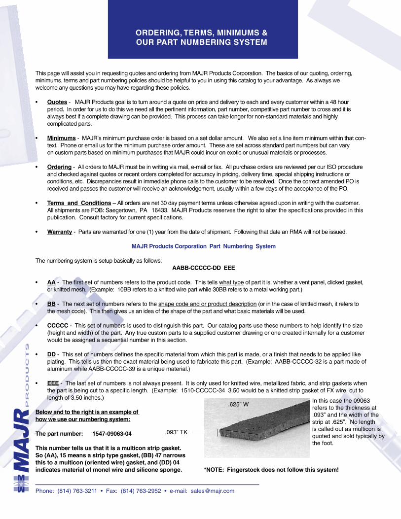
The part number: 1547-09063-04
This number tells us that it is a multicon strip gasket.So (AA), 15 means a strip type gasket, (BB) 47 narrows this to a multicon (oriented wire) gasket, and (DD) 04 indicates material of monel wire and silicone sponge. *NOTE: Fingerstock does not follow this system!
Phone: (814) 763-3211 • Fax: (814) 763-2952 • e-mail: [email protected]
.093” TK
.625” WIn this case the 09063 refers to the thickness at .093” and the width of the strip at .625”. No length is called out as multicon is quoted and sold typically by the foot.
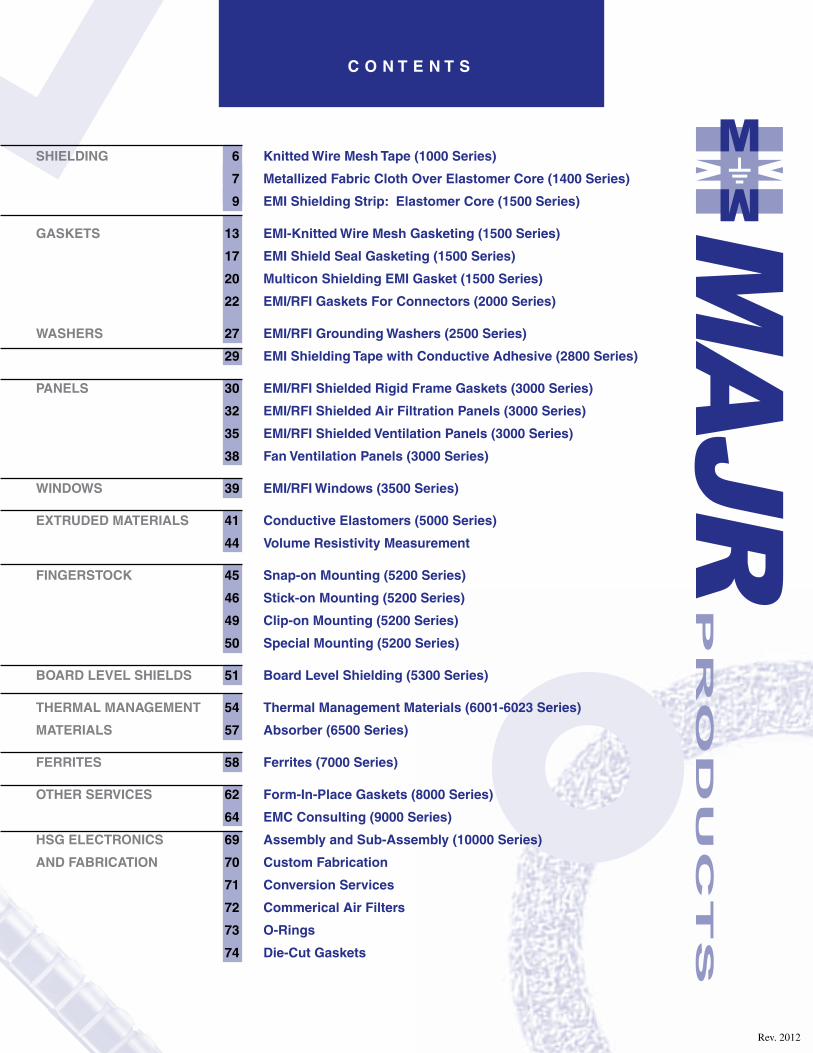
C O N T E N T S
Rev. 2012
SHIELDING 6 Knitted Wire Mesh Tape (1000 Series)
7 Metallized Fabric Cloth Over Elastomer Core (1400 Series)
9 EMI Shielding Strip: Elastomer Core (1500 Series)
GASKETS 13 EMI-Knitted Wire Mesh Gasketing (1500 Series)
17 EMI Shield Seal Gasketing (1500 Series)
20 Multicon Shielding EMI Gasket (1500 Series)
22 EMI/RFI Gaskets For Connectors (2000 Series)
WASHERS 27 EMI/RFI Grounding Washers (2500 Series)
29 EMI Shielding Tape with Conductive Adhesive (2800 Series)
PANELS 30 EMI/RFI Shielded Rigid Frame Gaskets (3000 Series)
32 EMI/RFI Shielded Air Filtration Panels (3000 Series)
35 EMI/RFI Shielded Ventilation Panels (3000 Series)
38 Fan Ventilation Panels (3000 Series)
WINDOWS 39 EMI/RFI Windows (3500 Series)
EXTRUDED MATERIALS 41 Conductive Elastomers (5000 Series)
44 Volume Resistivity Measurement
FINGERSTOCK 45 Snap-on Mounting (5200 Series)
46 Stick-on Mounting (5200 Series)
49 Clip-on Mounting (5200 Series)
50 Special Mounting (5200 Series)
BOARD LEVEL SHIELDS 51 Board Level Shielding (5300 Series)
THERMAL MANAGEMENT 54 Thermal Management Materials (6001-6023 Series)
MATERIALS 57 Absorber (6500 Series)
FERRITES 58 Ferrites (7000 Series)
OTHER SERVICES 62 Form-In-Place Gaskets (8000 Series)
64 EMC Consulting (9000 Series)
HSG ELECTRONICS 69 Assembly and Sub-Assembly (10000 Series)
AND FABRICATION 70 Custom Fabrication
71 Conversion Services
72 Commerical Air Filters
73 O-Rings
74 Die-Cut Gaskets
Phone: (814) 763-3211 • Fax: (814) 763-2952 • e-mail: [email protected]
6
Knitted Wire Mesh Tape (1000 Series)
SH
IEL
DIN
G -
KN
ITT
ED
WIR
E M
ES
H
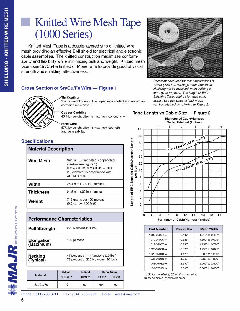
Knitted Mesh Tape is a double-layered strip of knitted wire mesh providing an effective EMI shield for electrical and electronic cable assemblies. The knitted construction maximizes conform-ability and flexibility while minimizing bulk and weight. Knitted mesh tape uses Sn/Cu/Fe knitted or Monel wire to provide good physical strength and shielding effectiveness.
Cross Section of Sn/Cu/Fe Wire — Figure 1
Tin Coating3% by weight offering low impedance contact and maximum corrosion resistance.
Copper Cladding40% by weight offering maximum conductivity.
Steel Core57% by weight offering maximum strength and permeability.
Specifications
Tape Length vs Cable Size — Figure 2
Recommended lead for most applications is 13mm (0.50 in.), although some additional shielding will be achieved when utilizing a 6mm (0.25 in.) lead. The length of EMC Shielding Tape required for each cable using these two types of lead wraps can be obtained by referring to Figure 2.
Material Description
Performance Characteristics
Wire Mesh
Width
Thickness
Weight
Sn/Cu/FE (tin-coated, copper-clad steel — see Figure 1) 0.114 + 0.012 mm (.0045 + .0005 in.) diameter in accordance with ASTM B-520.
25.4 mm (1.00 in.) nominal
0.45 mm (.02 in.) nominal.
745 grams per 100 meters(8.0 oz. per 100 feet)
Pull Strength
Elongation (Maximum)
Necking (Typical)
222 Newtons (50 lbs.)
100 percent
47 percent at 111 Newtons (25 lbs.)75 percent at 222 Newtons (50 lbs.)
Sn/Cu/Fe
MaterialE-Field
10MHz
Plane Wave
1 GHz 10GHz
45 60
40
H-Field
100 kHz
Part Number Sleeve Dia. Mesh Width
1008-07004-xx 0.437” 0.312” to 0.437”
1012-07006-xx 0.625” 0.500” to 0.625”
1016-07007-xx 0.750” 0.625” to 0.750”
1020-07008-xx 0.875” 0.750” to 0.875”
1026-07010-xx 1.125” 1.000” to 1.250”
1034-07016-xx 1.250” 1.250” to 1.500”
1042-07022-xx 2.250” 2.000” to 2.500”
1100-07065-xx 5.500” 7.000” to 8.000”
xx: 31 for monel wire; 32 for aluminum wire; 34 for tin-plated, copperclad steel.
30
Phone: (814) 763-3211 • Fax: (814) 763-2952 • e-mail: [email protected]
7
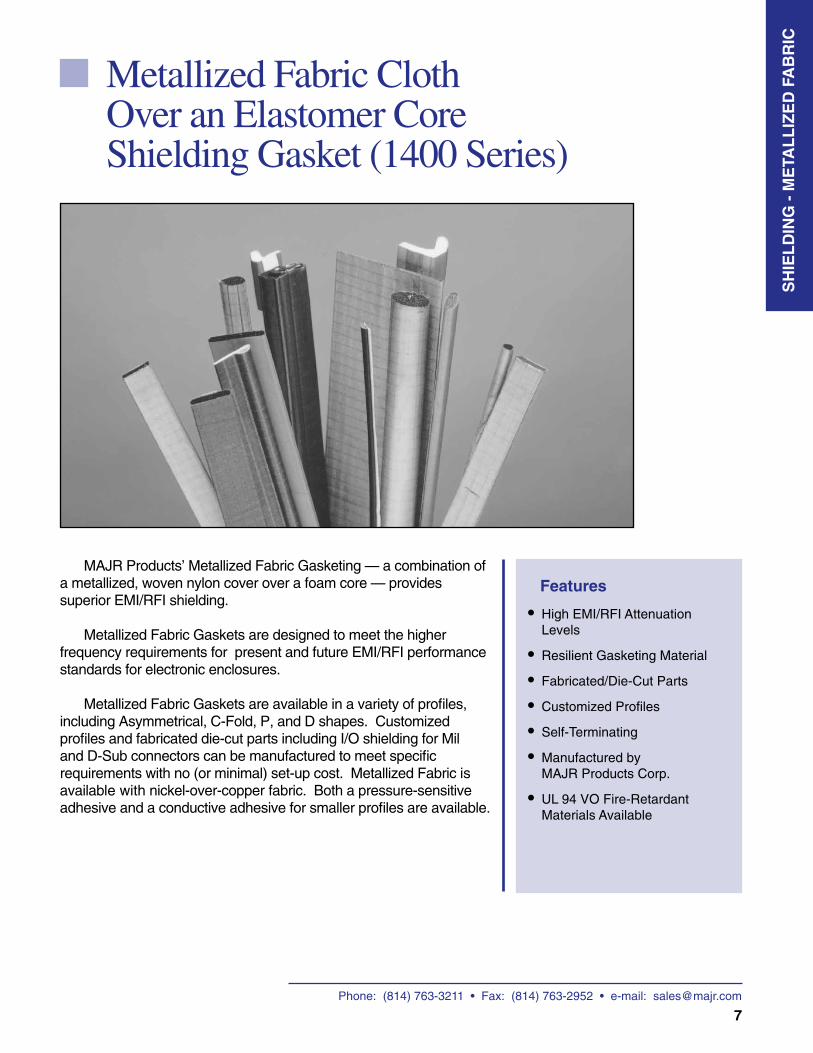
Metallized Fabric Cloth Over an Elastomer CoreShielding Gasket (1400 Series)
Features
High EMI/RFI Attenuation Levels
Resilient Gasketing Material
Fabricated/Die-Cut Parts
Customized Profiles
Self-Terminating
Manufactured by MAJR Products Corp.
UL 94 VO Fire-Retardant Materials Available
MAJR Products’ Metallized Fabric Gasketing — a combination of a metallized, woven nylon cover over a foam core — provides superior EMI/RFI shielding.
Metallized Fabric Gaskets are designed to meet the higher frequency requirements for present and future EMI/RFI performance standards for electronic enclosures.
Metallized Fabric Gaskets are available in a variety of profiles, including Asymmetrical, C-Fold, P, and D shapes. Customized profiles and fabricated die-cut parts including I/O shielding for Mil and D-Sub connectors can be manufactured to meet specific requirements with no (or minimal) set-up cost. Metallized Fabric is available with nickel-over-copper fabric. Both a pressure-sensitive adhesive and a conductive adhesive for smaller profiles are available.
• ••••• •
SH
IEL
DIN
G -
ME
TAL
LIZ
ED
FA
BR
IC
Phone: (814) 763-3211 • Fax: (814) 763-2952 • e-mail: [email protected]
8
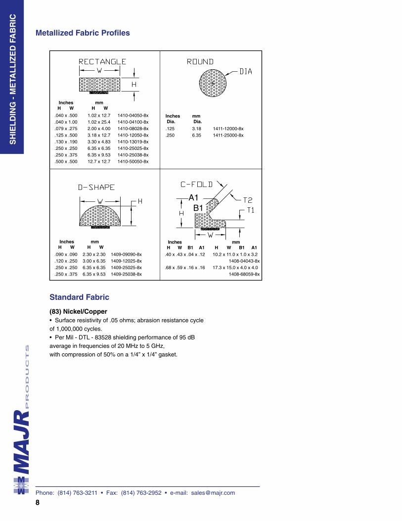
Metallized Fabric Profiles
Standard Fabric
(83) Nickel/Copper• Surface resistivity of .05 ohms; abrasion resistance cycle of 1,000,000 cycles.• Per Mil - DTL - 83528 shielding performance of 95 dB average in frequencies of 20 MHz to 5 GHz, with compression of 50% on a 1/4” x 1/4” gasket.
Inches mm H W H W
.040 x .500 1.02 x 12.7 1410-04050-8x
.040 x 1.00 1.02 x 25.4 1410-04100-8x
.079 x .275 2.00 x 4.00 1410-08028-8x
.125 x .500 3.18 x 12.7 1410-12050-8x
.130 x .190 3.30 x 4.83 1410-13019-8x
.250 x .250 6.35 x 6.35 1410-25025-8x
.250 x .375 6.35 x 9.53 1410-25038-8x
.500 x .500 12.7 x 12.7 1410-50050-8x
.125 3.18 1411-12000-8x
.250 6.35 1411-25000-8x
Inches mm Dia. Dia.
.40 x .43 x .04 x .12 10.2 x 11.0 x 1.0 x 3.2 1408-04043-8x.68 x .59 x .16 x .16 17.3 x 15.0 x 4.0 x 4.0 1408-68059-8x
Inches mm H W B1 A1 H W B1 A1
A1B1
SH
IEL
DIN
G -
ME
TAL
LIZ
ED
FA
BR
IC
.090 x .090 2.30 x 2.30 1409-09090-8x
.120 x .250 3.00 x 6.35 1409-12025-8x
.250 x .250 6.35 x 6.35 1409-25025-8x
.250 x .375 6.35 x 9.53 1409-25038-8x
Inches mm H W H W
Phone: (814) 763-3211 • Fax: (814) 763-2952 • e-mail: [email protected]
9
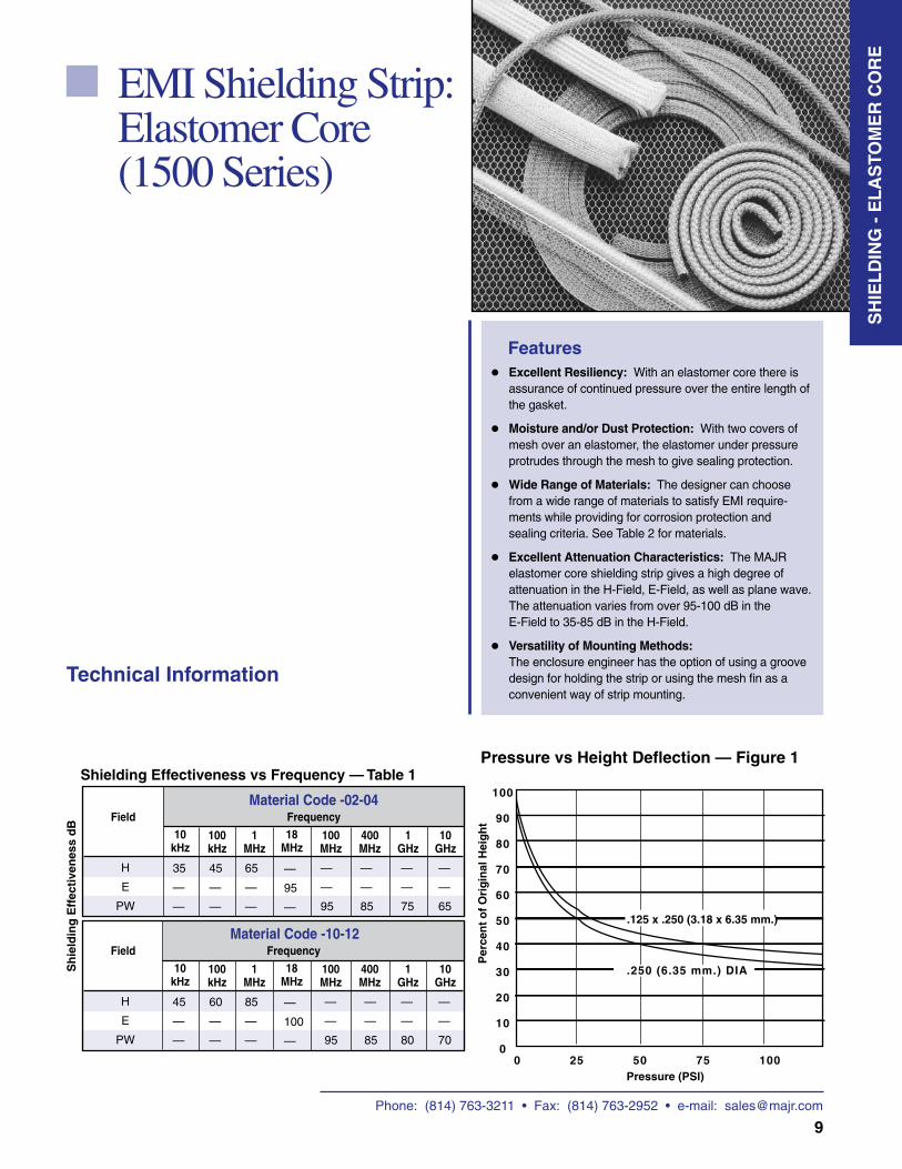
EMI Shielding Strip:Elastomer Core (1500 Series)
Features•
• • • •
Excellent Resiliency: With an elastomer core there is assurance of continued pressure over the entire length of the gasket.
Moisture and/or Dust Protection: With two covers of mesh over an elastomer, the elastomer under pressure protrudes through the mesh to give sealing protection.
Wide Range of Materials: The designer can choose from a wide range of materials to satisfy EMI require-ments while providing for corrosion protection and sealing criteria. See Table 2 for materials.
Excellent Attenuation Characteristics: The MAJR elastomer core shielding strip gives a high degree of attenuation in the H-Field, E-Field, as well as plane wave. The attenuation varies from over 95-100 dB in the E-Field to 35-85 dB in the H-Field.
Versatility of Mounting Methods: The enclosure engineer has the option of using a groove design for holding the strip or using the mesh fin as a convenient way of strip mounting.
Pressure vs Height Deflection — Figure 1
H
E
PW
35
—
—
45
—
—
65
—
—
—
95
—
FieldMaterial Code -02-04
10 kHz
100 kHz
1 MHz
18 MHz
Sh
ield
ing
Eff
ecti
ven
ess
dB
100 MHz
400 MHz
Frequency
1 GHz
—
—
95
—
—
85
—
—
75
H
E
PW
45
—
—
60
—
—
85
—
—
—
100
—
FieldMaterial Code -10-12
10 kHz
100 kHz
1 MHz
18 MHz
100 MHz
400 MHz
Frequency
1 GHz
—
—
95
—
—
85
—
—
80
Shielding Effectiveness vs Frequency — Table 1
Technical Information
10 GHz
—
—
65
10 GHz
—
—
70
SH
IEL
DIN
G -
EL
AS
TOM
ER
CO
RE
Phone: (814) 763-3211 • Fax: (814) 763-2952 • e-mail: [email protected]
10
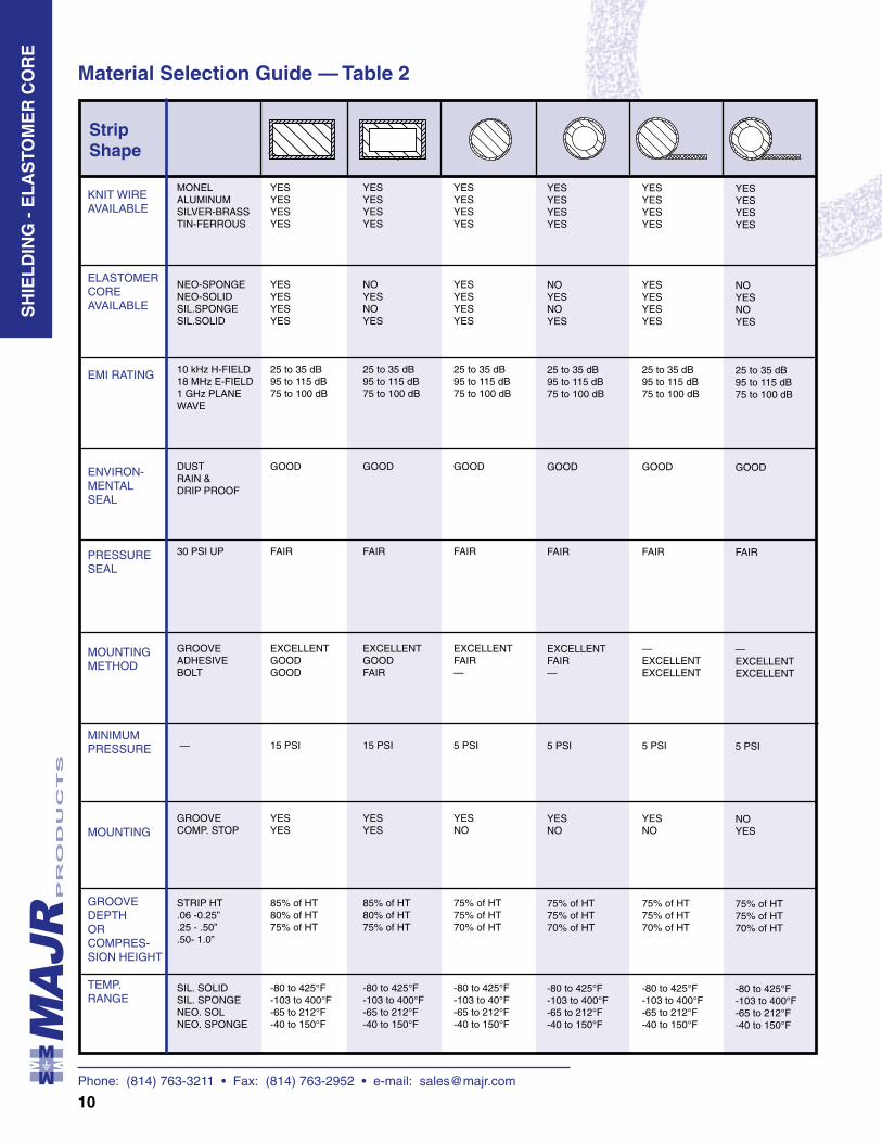
Material Selection Guide — Table 2
MONEL ALUMINUM SILVER-BRASS TIN-FERROUS NEO-SPONGE NEO-SOLID SIL.SPONGE SIL.SOLID 10 kHz H-FIELD 18 MHz E-FIELD 1 GHz PLANE WAVE DUST RAIN & DRIP PROOF 30 PSI UP GROOVE ADHESIVE BOLT — GROOVE COMP. STOP STRIP HT .06 -0.25” .25 - .50” .50- 1.0” SIL. SOLID SIL. SPONGE NEO. SOL NEO. SPONGE
KNIT WIRE AVAILABLE ELASTOMER CORE AVAILABLE EMI RATING
ENVIRON-MENTAL SEAL
PRESSURE SEAL
MOUNTING METHOD
MINIMUM PRESSURE
MOUNTING
GROOVE DEPTH OR COMPRES-SION HEIGHT
TEMP. RANGE
Strip Shape
YES YES YES YES
YES YES YES YES
25 to 35 dB95 to 115 dB75 to 100 dB
GOOD
FAIR
EXCELLENT GOOD GOOD
15 PSI
YESYES
85% of HT80% of HT75% of HT
-80 to 425°F-103 to 400°F-65 to 212°F-40 to 150°F
YES YES YESYES
NO YES NO YES
25 to 35 dB95 to 115 dB75 to 100 dB
GOOD
FAIR
EXCELLENT GOODFAIR
15 PSI
YES YES
85% of HT80% of HT75% of HT
-80 to 425°F-103 to 400°F-65 to 212°F-40 to 150°F
YES YES YES YES
YES YES YES YES
25 to 35 dB95 to 115 dB75 to 100 dB
GOOD
FAIR
EXCELLENT FAIR—
5 PSI
YESNO
75% of HT75% of HT70% of HT
-80 to 425°F-103 to 40°F-65 to 212°F-40 to 150°F
YES YES YES YES
NO YES NO YES
25 to 35 dB95 to 115 dB75 to 100 dB
GOOD
FAIR
EXCELLENTFAIR—
5 PSI
YESNO
75% of HT75% of HT70% of HT
-80 to 425°F-103 to 400°F-65 to 212°F-40 to 150°F
YES YES YES YES
YES YES YES YES
25 to 35 dB95 to 115 dB75 to 100 dB
GOOD
FAIR —EXCELLENTEXCELLENT
5 PSI
YES NO
75% of HT75% of HT70% of HT
-80 to 425°F-103 to 400°F-65 to 212°F-40 to 150°F
YES YES YES YES
NO YES NO YES
25 to 35 dB95 to 115 dB75 to 100 dB
GOOD
FAIR
—EXCELLENTEXCELLENT
5 PSI
NO YES
75% of HT75% of HT70% of HT
-80 to 425°F-103 to 400°F-65 to 212°F-40 to 150°F
SH
IEL
DIN
G -
EL
AS
TOM
ER
CO
RE
Phone: (814) 763-3211 • Fax: (814) 763-2952 • e-mail: [email protected]
11
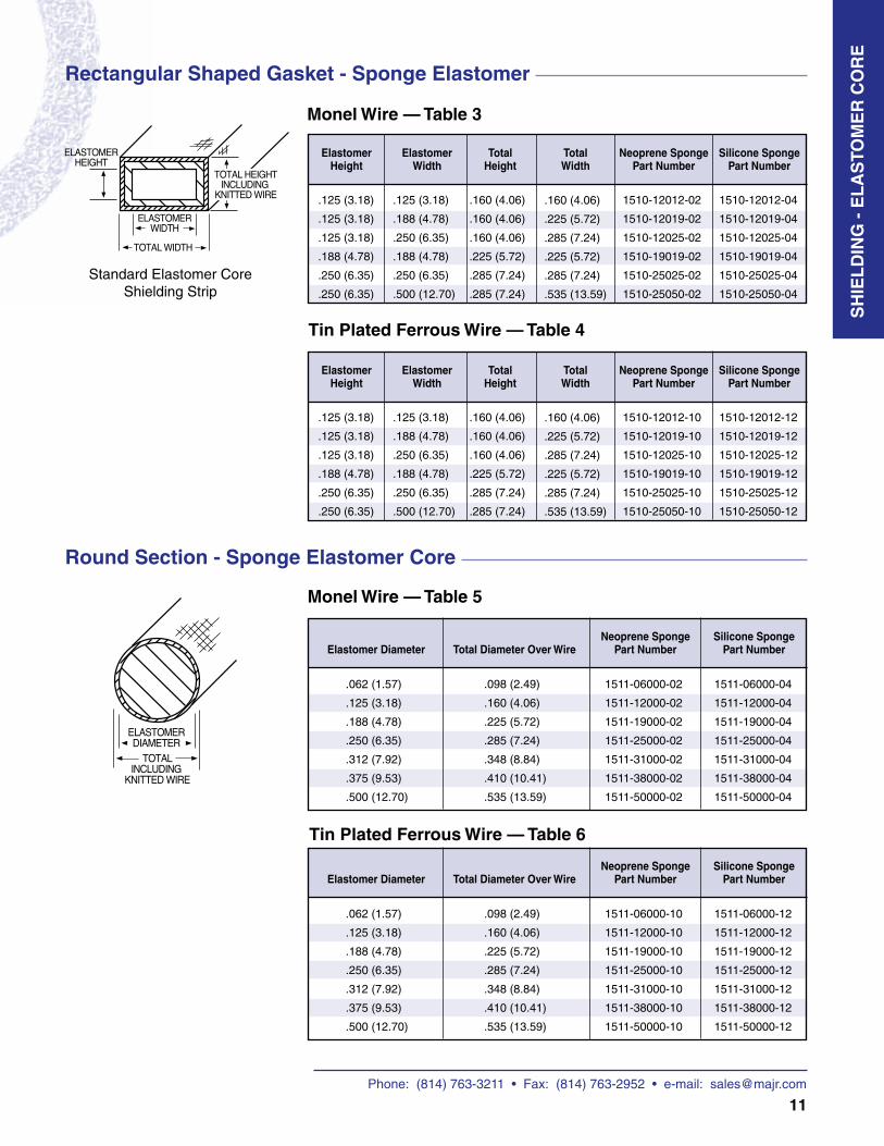
Monel Wire — Table 5
Round Section - Sponge Elastomer Core
Rectangular Shaped Gasket - Sponge Elastomer
Standard Elastomer Core Shielding Strip
Monel Wire — Table 3
.125 (3.18)
.125 (3.18)
.125 (3.18)
.188 (4.78)
.250 (6.35)
.250 (6.35)
.125 (3.18)
.188 (4.78)
.250 (6.35)
.188 (4.78)
.250 (6.35)
.500 (12.70)
.160 (4.06)
.160 (4.06)
.160 (4.06)
.225 (5.72)
.285 (7.24)
.285 (7.24)
.160 (4.06)
.225 (5.72)
.285 (7.24)
.225 (5.72)
.285 (7.24)
.535 (13.59)
1510-12012-02
1510-12019-02
1510-12025-02
1510-19019-02
1510-25025-02
1510-25050-02
1510-12012-04
1510-12019-04
1510-12025-04
1510-19019-04
1510-25025-04
1510-25050-04
Tin Plated Ferrous Wire — Table 4
Tin Plated Ferrous Wire — Table 6
ElastomerHeight
Elastomer Width
Total Height
Total Width
Neoprene Sponge Part Number
Silicone Sponge Part Number
.125 (3.18)
.125 (3.18)
.125 (3.18)
.188 (4.78)
.250 (6.35)
.250 (6.35)
.125 (3.18)
.188 (4.78)
.250 (6.35)
.188 (4.78)
.250 (6.35)
.500 (12.70)
.160 (4.06)
.160 (4.06)
.160 (4.06)
.225 (5.72)
.285 (7.24)
.285 (7.24)
.160 (4.06)
.225 (5.72)
.285 (7.24)
.225 (5.72)
.285 (7.24)
.535 (13.59)
1510-12012-10
1510-12019-10
1510-12025-10
1510-19019-10
1510-25025-10
1510-25050-10
1510-12012-12
1510-12019-12
1510-12025-12
1510-19019-12
1510-25025-12
1510-25050-12
ElastomerHeight
Elastomer Width
Total Height
Total Width
Neoprene Sponge Part Number
Silicone Sponge Part Number
Elastomer Diameter Total Diameter Over WireNeoprene Sponge
Part NumberSilicone Sponge
Part Number
.062 (1.57)
.125 (3.18)
.188 (4.78)
.250 (6.35)
.312 (7.92)
.375 (9.53)
.500 (12.70)
.098 (2.49)
.160 (4.06)
.225 (5.72)
.285 (7.24)
.348 (8.84)
.410 (10.41)
.535 (13.59)
1511-06000-02
1511-12000-02
1511-19000-02
1511-25000-02
1511-31000-02
1511-38000-02
1511-50000-02
1511-06000-04
1511-12000-04
1511-19000-04
1511-25000-04
1511-31000-04
1511-38000-04
1511-50000-04
Elastomer Diameter Total Diameter Over WireNeoprene Sponge
Part NumberSilicone Sponge
Part Number
.062 (1.57)
.125 (3.18)
.188 (4.78)
.250 (6.35)
.312 (7.92)
.375 (9.53)
.500 (12.70)
.098 (2.49)
.160 (4.06)
.225 (5.72)
.285 (7.24)
.348 (8.84)
.410 (10.41)
.535 (13.59)
1511-06000-10
1511-12000-10
1511-19000-10
1511-25000-10
1511-31000-10
1511-38000-10
1511-50000-10
1511-06000-12
1511-12000-12
1511-19000-12
1511-25000-12
1511-31000-12
1511-38000-12
1511-50000-12
SH
IEL
DIN
G -
EL
AS
TOM
ER
CO
RE
Phone: (814) 763-3211 • Fax: (814) 763-2952 • e-mail: [email protected]
12
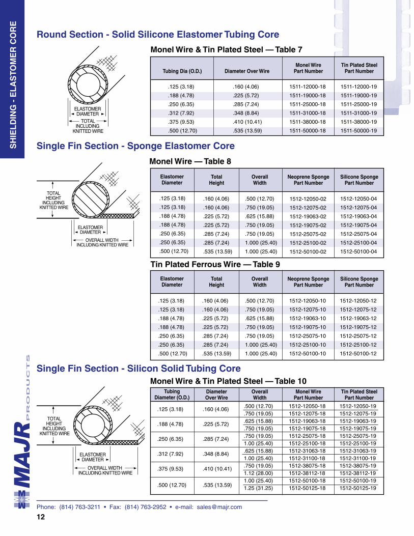
Diameter Over Wire
Single Fin Section - Sponge Elastomer Core
Single Fin Section - Silicon Solid Tubing Core
Round Section - Solid Silicone Elastomer Tubing Core
Monel Wire — Table 8
Tin Plated Ferrous Wire — Table 9
Monel Wire & Tin Plated Steel — Table 7
Monel Wire & Tin Plated Steel — Table 10
Tubing Dia (O.D.) Diameter Over WireMonel Wire
Part NumberTin Plated Steel
Part Number
.125 (3.18)
.188 (4.78)
.250 (6.35)
.312 (7.92)
.375 (9.53)
.500 (12.70)
.160 (4.06)
.225 (5.72)
.285 (7.24)
.348 (8.84)
.410 (10.41)
.535 (13.59)
1511-12000-18
1511-19000-18
1511-25000-18
1511-31000-18
1511-38000-18
1511-50000-18
1511-12000-19
1511-19000-19
1511-25000-19
1511-31000-19
1511-38000-19
1511-50000-19
Elastomer Diameter
Total Height
Neoprene Sponge Part Number
Silicone Sponge Part Number
Overall Width
Elastomer Diameter
Total Height
Neoprene Sponge Part Number
Silicone Sponge Part Number
Overall Width
.125 (3.18)
.125 (3.18)
.188 (4.78)
.188 (4.78)
.250 (6.35)
.250 (6.35)
.500 (12.70)
.160 (4.06)
.160 (4.06)
.225 (5.72)
.225 (5.72)
.285 (7.24)
.285 (7.24)
.535 (13.59)
.500 (12.70)
.750 (19.05)
.625 (15.88)
.750 (19.05)
.750 (19.05)
1.000 (25.40)
1.000 (25.40)
1512-12050-10
1512-12075-10
1512-19063-10
1512-19075-10
1512-25075-10
1512-25100-10
1512-50100-10
1512-12050-12
1512-12075-12
1512-19063-12
1512-19075-12
1512-25075-12
1512-25100-12
1512-50100-12
.125 (3.18)
.125 (3.18)
.188 (4.78)
.188 (4.78)
.250 (6.35)
.250 (6.35)
.500 (12.70)
.160 (4.06)
.160 (4.06)
.225 (5.72)
.225 (5.72)
.285 (7.24)
.285 (7.24)
.535 (13.59)
.500 (12.70)
.750 (19.05)
.625 (15.88)
.750 (19.05)
.750 (19.05)
1.000 (25.40)
1.000 (25.40)
1512-12050-02
1512-12075-02
1512-19063-02
1512-19075-02
1512-25075-02
1512-25100-02
1512-50100-02
1512-12050-04
1512-12075-04
1512-19063-04
1512-19075-04
1512-25075-04
1512-25100-04
1512-50100-04
Tubing Diameter (O.D.)
Monel Wire Part Number
Tin Plated Steel Part Number
Overall Width
.125 (3.18)
.188 (4.78)
.250 (6.35)
.312 (7.92)
.375 (9.53)
.500 (12.70)
.160 (4.06)
.225 (5.72)
.285 (7.24)
.348 (8.84)
.410 (10.41)
.535 (13.59)
.500 (12.70)
.750 (19.05)
.625 (15.88)
.750 (19.05)
.750 (19.05)1.00 (25.40).625 (15.88)1.00 (25.40).750 (19.05)1.12 (28.00)1.00 (25.40)1.25 (31.25)
1512-12050-181512-12075-181512-19063-181512-19075-181512-25075-181512-25100-181512-31063-181512-31100-181512-38075-181512-38112-181512-50100-181512-50125-18
1512-12050-191512-12075-191512-19063-191512-19075-191512-25075-191512-25100-191512-31063-191512-31100-191512-38075-191512-38112-191512-50100-191512-50125-19
SH
IEL
DIN
G -
EL
AS
TOM
ER
CO
RE
Phone: (814) 763-3211 • Fax: (814) 763-2952 • e-mail: [email protected]
13
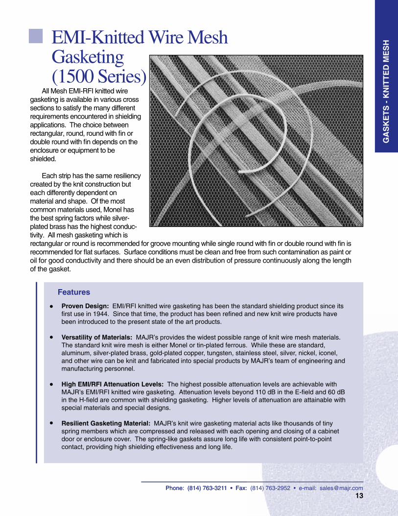
EMI-Knitted Wire Mesh Gasketing (1500 Series)
Features
• •
•
•
G A
S K
E T
S
Proven Design: EMI/RFI knitted wire gasketing has been the standard shielding product since its first use in 1944. Since that time, the product has been refined and new knit wire products have been introduced to the present state of the art products.
Versatility of Materials: MAJR’s provides the widest possible range of knit wire mesh materials. The standard knit wire mesh is either Monel or tin-plated ferrous. While these are standard, aluminum, silver-plated brass, gold-plated copper, tungsten, stainless steel, silver, nickel, iconel, and other wire can be knit and fabricated into special products by MAJR’s team of engineering and manufacturing personnel.
High EMI/RFI Attenuation Levels: The highest possible attenuation levels are achievable with MAJR’s EMI/RFI knitted wire gasketing. Attenuation levels beyond 110 dB in the E-field and 60 dB in the H-field are common with shielding gasketing. Higher levels of attenuation are attainable with special materials and special designs.
Resilient Gasketing Material: MAJR’s knit wire gasketing material acts like thousands of tiny spring members which are compressed and released with each opening and closing of a cabinet door or enclosure cover. The spring-like gaskets assure long life with consistent point-to-point contact, providing high shielding effectiveness and long life.
All Mesh EMI-RFI knitted wire gasketing is available in various cross sections to satisfy the many different requirements encountered in shielding applications. The choice between rectangular, round, round with fin or double round with fin depends on the enclosure or equipment to be shielded.
Each strip has the same resiliency created by the knit construction but each differently dependent on material and shape. Of the most common materials used, Monel has the best spring factors while silver-plated brass has the highest conduc-tivity. All mesh gasketing which is rectangular or round is recommended for groove mounting while single round with fin or double round with fin is recommended for flat surfaces. Surface conditions must be clean and free from such contamination as paint or oil for good conductivity and there should be an even distribution of pressure continuously along the length of the gasket.
GA
SK
ET
S -
KN
ITT
ED
ME
SH
Phone: (814) 763-3211 • Fax: (814) 763-2952 • e-mail: [email protected]
Phone: (814) 763-3211 • Fax: (814) 763-2952 • e-mail: [email protected]
14
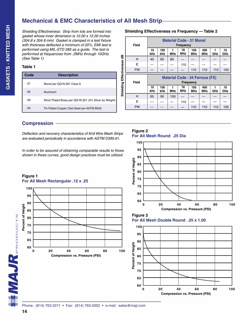
Mechanical & EMC Characteristics of All Mesh Strip
Shielding Effectiveness: Strip from lots are formed into gasket whose inner dimension is 12.00 x 12.00 inches (304.8 x 304.8 mm) Gasket is clamped in a test fixture with thickness deflected a minimum of 20%, EMI test is performed using MIL-STD 285 as a guide. The test is performed at frequencies from .2MHz through 10GHz. (See Table 1)
Deflection and recovery characteristics of Knit Wire Mesh Strips are evaluated periodically in accordance with ASTM D395-61.
H
E
PW
40
—
—
60
—
—
80
—
—
—
110
—
FieldMaterial Code - 31 Monel
10 kHz
100 kHz
1 MHz
18 MHz
Sh
ield
ing
Eff
ecti
ven
ess
dB
100 MHz
400 MHz
Frequency
1 GHz
—
—
110
—
—
110
—
—
110
H
E
PW
65
—
—
90
—
—
100
—
—
—
110
—
FieldMaterial Code - 34 Ferrous (FX)
10 kHz
100 kHz
1 MHz
18 MHz
100 MHz
400 MHz
Frequency
1 GHz
—
—
110
—
—
110
—
—
110
Shielding Effectiveness vs Frequency — Table 2
Compression
In order to be assured of obtaining comparable results to those shown in these curves, good design practices must be utilized.
Figure 3For All Mesh Double Round .25 x 1.00
Figure 1For All Mesh Rectangular .12 x .25
Figure 2For All Mesh Round .25 Dia
10 GHz
—
—
100
10 GHz
—
—
100
GA
SK
ET
S -
KN
ITT
ED
ME
SH
Code Description
Table 1
Monel per QQ-N-281 Class A
Aluminum
Silver Plated Brass per QQ-W-321 (3% Silver by Weight)
Tin Plated Copper Clad Steel per ASTM B520
-31
-32
-33
-34
Phone: (814) 763-3211 • Fax: (814) 763-2952 • e-mail: [email protected]
15
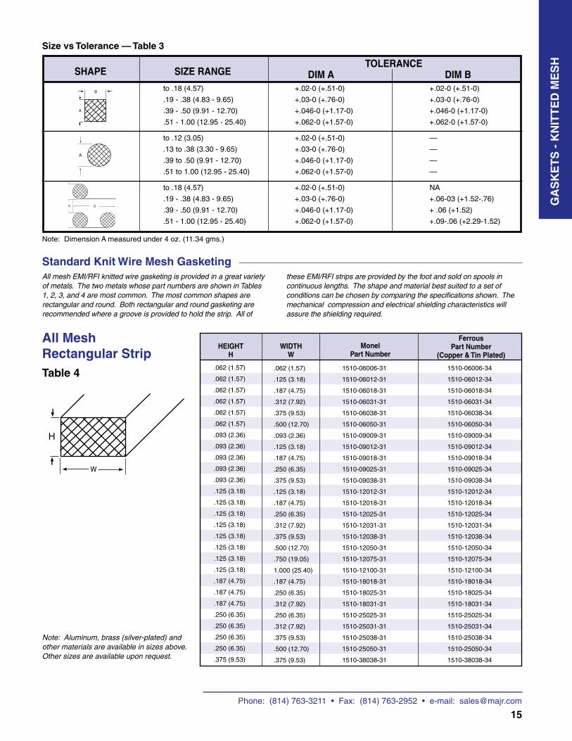
All Mesh Rectangular StripTable 4
HEIGHTH
WIDTHW
Monel
Part Number
Ferrous Part Number
(Copper & Tin Plated)
Size vs Tolerance — Table 3
DIM A DIM BSHAPETOLERANCE
SIZE RANGE
to .18 (4.57)
.19 - .38 (4.83 - 9.65)
.39 - .50 (9.91 - 12.70)
.51 - 1.00 (12.95 - 25.40)
to .12 (3.05)
.13 to .38 (3.30 - 9.65)
.39 to .50 (9.91 - 12.70)
.51 to 1.00 (12.95 - 25.40)
to .18 (4.57)
.19 - .38 (4.83 - 9.65)
.39 - .50 (9.91 - 12.70)
.51 - 1.00 (12.95 - 25.40)
Note: Dimension A measured under 4 oz. (11.34 gms.)
+.02-0 (+.51-0) +.02-0 (+.51-0)
+.03-0 (+.76-0) +.03-0 (+.76-0)
+.046-0 (+1.17-0) +.046-0 (+1.17-0)
+.062-0 (+1.57-0) +.062-0 (+1.57-0)
+.02-0 (+.51-0) —
+.03-0 (+.76-0) —
+.046-0 (+1.17-0) —
+.062-0 (+1.57-0) —
+.02-0 (+.51-0) NA
+.03-0 (+.76-0) +.06-03 (+1.52-.76)
+.046-0 (+1.17-0) + .06 (+1.52)
+.062-0 (+1.57-0) +.09-.06 (+2.29-1.52)
All mesh EMI/RFI knitted wire gasketing is provided in a great variety of metals. The two metals whose part numbers are shown in Tables 1, 2, 3, and 4 are most common. The most common shapes are rectangular and round. Both rectangular and round gasketing are recommended where a groove is provided to hold the strip. All of
Standard Knit Wire Mesh Gasketing
.062 (1.57)
.062 (1.57)
.062 (1.57)
.062 (1.57)
.062 (1.57)
.062 (1.57)
.093 (2.36)
.093 (2.36)
.093 (2.36)
.093 (2.36)
.093 (2.36)
.125 (3.18)
.125 (3.18)
.125 (3.18)
.125 (3.18)
.125 (3.18)
.125 (3.18)
.125 (3.18)
.125 (3.18)
.187 (4.75)
.187 (4.75)
.187 (4.75)
.250 (6.35)
.250 (6.35)
.250 (6.35)
.250 (6.35)
.375 (9.53)
.062 (1.57)
.125 (3.18)
.187 (4.75)
.312 (7.92)
.375 (9.53)
.500 (12.70)
.093 (2.36)
.125 (3.18)
.187 (4.75)
.250 (6.35)
.375 (9.53)
.125 (3.18)
.187 (4.75)
.250 (6.35)
.312 (7.92)
.375 (9.53)
.500 (12.70)
.750 (19.05)
1.000 (25.40)
.187 (4.75)
.250 (6.35)
.312 (7.92)
.250 (6.35)
.312 (7.92)
.375 (9.53)
.500 (12.70)
.375 (9.53)
1510-06006-31
1510-06012-31
1510-06018-31
1510-06031-31
1510-06038-31
1510-06050-31
1510-09009-31
1510-09012-31
1510-09018-31
1510-09025-31
1510-09038-31
1510-12012-31
1510-12018-31
1510-12025-31
1510-12031-31
1510-12038-31
1510-12050-31
1510-12075-31
1510-12100-31
1510-18018-31
1510-18025-31
1510-18031-31
1510-25025-31
1510-25031-31
1510-25038-31
1510-25050-31
1510-38038-31
1510-06006-34
1510-06012-34
1510-06018-34
1510-06031-34
1510-06038-34
1510-06050-34
1510-09009-34
1510-09012-34
1510-09018-34
1510-09025-34
1510-09038-34
1510-12012-34
1510-12018-34
1510-12025-34
1510-12031-34
1510-12038-34
1510-12050-34
1510-12075-34
1510-12100-34
1510-18018-34
1510-18025-34
1510-18031-34
1510-25025-34
1510-25031-34
1510-25038-34
1510-25050-34
1510-38038-34
Note: Aluminum, brass (silver-plated) and other materials are available in sizes above. Other sizes are available upon request.
these EMI/RFI strips are provided by the foot and sold on spools in continuous lengths. The shape and material best suited to a set of conditions can be chosen by comparing the specifications shown. The mechanical compression and electrical shielding characteristics will assure the shielding required.
GA
SK
ET
S -
KN
ITT
ED
ME
SH
H
Phone: (814) 763-3211 • Fax: (814) 763-2952 • e-mail: [email protected]
16
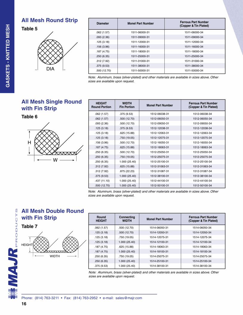
All Mesh Double Round with Fin Strip
Table 7
All Mesh Single Round with Fin StripTable 6
HEIGHTRound Portion
Monel Part Number
Ferrous Part Number(Copper & Tin Plated)
WIDTHFin Portion
.062 (1.57)
.062 (1.57)
.093 (2.36)
.125 (3.18)
.125 (3.18)
.125 (3.18)
.156 (3.96)
.187 (4.75)
.250 (6.35)
.250 (6.35)
.250 (6.35)
.312 (7.92)
.312 (7.92)
.375 (9.53)
.437 (11.10)
.500 (12.70)
.375 (9.53)
.500 (12.70)
.500 (12.70)
.375 (9.53)
.625 (15.88)
.750 (19.05)
.500 (12.70)
.625 (15.88)
.500 (12.70)
.750 (19.05)
1.000 (25.40)
.625 (15.88)
.875 (22.23)
1.000 (25.40)
1.000 (25.40)
1.000 (25.40)
1512-06038-31
1512-06050-31
1512-09050-31
1512-12038-31
1512-12063-31
1512-12075-31
1512-16050-31
1512-18063-31
1512-25050-31
1512-25075-31
1512-25100-31
1512-31063-31
1512-31087-31
1512-38100-31
1512-44100-31
1512-50100-31
1512-06038-34
1512-06050-34
1512-09050-34
1512-12038-34
1512-12063-34
1512-12075-34
1512-16050-34
1512-18063-34
1512-25050-34
1512-25075-34
1512-25100-34
1512-31063-34
1512-31087-34
1512-38100-34
1512-44100-34
1512-50100-34
Note: Aluminum, brass (silver-plated) and other materials are available in sizes above. Other sizes are available upon request.
All Mesh Round StripTable 5
Diameter
Monel Part Number Ferrous Part Number(Copper & Tin Plated)
.062 (1.57)
.093 (2.36)
.125 (3.18)
.156 (3.96)
.187 (4.75)
.250 (6.35)
.312 (7.92)
.375 (9.53)
.500 (12.70)
1511-06000-31
1511-09000-31
1511-12000-31
1511-16000-31
1511-18000-31
1511-25000-31
1511-31000-31
1511-38000-31
1511-50000-31
1511-06000-34
1511-09000-34
1511-12000-34
1511-16000-34
1511-18000-34
1511-25000-34
1511-31000-34
1511-38000-34
1511-50000-34
Note: Aluminum, brass (silver-plated) and other materials are available in sizes above. Other sizes are available upon request.
RoundHEIGHT
Monel Part Number
Ferrous Part Number(Copper & Tin Plated)
ConnectingWIDTH
.062 (1.57)
.125 (3.18)
.125 (3.18)
.125 (3.18)
.187 (4.75)
.187 (4.75)
.250 (6.35)
.250 (6.35)
.375 (9.53)
.500 (12.70)
.500 (12.70)
.750 (19.05)
1.000 (25.40)
.625 (15.88)
1.000 (25.40)
.750 (19.05)
1.000 (25.40)
1.000 (25.40)
1514-06050-31
1514-12050-31
1514-12075-31
1514-12100-31
1514-18063-31
1514-18100-31
1514-25075-31
1514-25100-31
1514-38100-31
1514-06050-34
1514-12050-34
1514-12075-34
1514-12100-34
1514-18063-34
1514-18100-34
1514-25075-34
1514-25100-34
1514-38100-34
Note: Aluminum, brass (silver-plated) and other materials are available in sizes above. Other sizes are available upon request.
GA
SK
ET
S -
KN
ITT
ED
ME
SH
Phone: (814) 763-3211 • Fax: (814) 763-2952 • e-mail: [email protected]
17
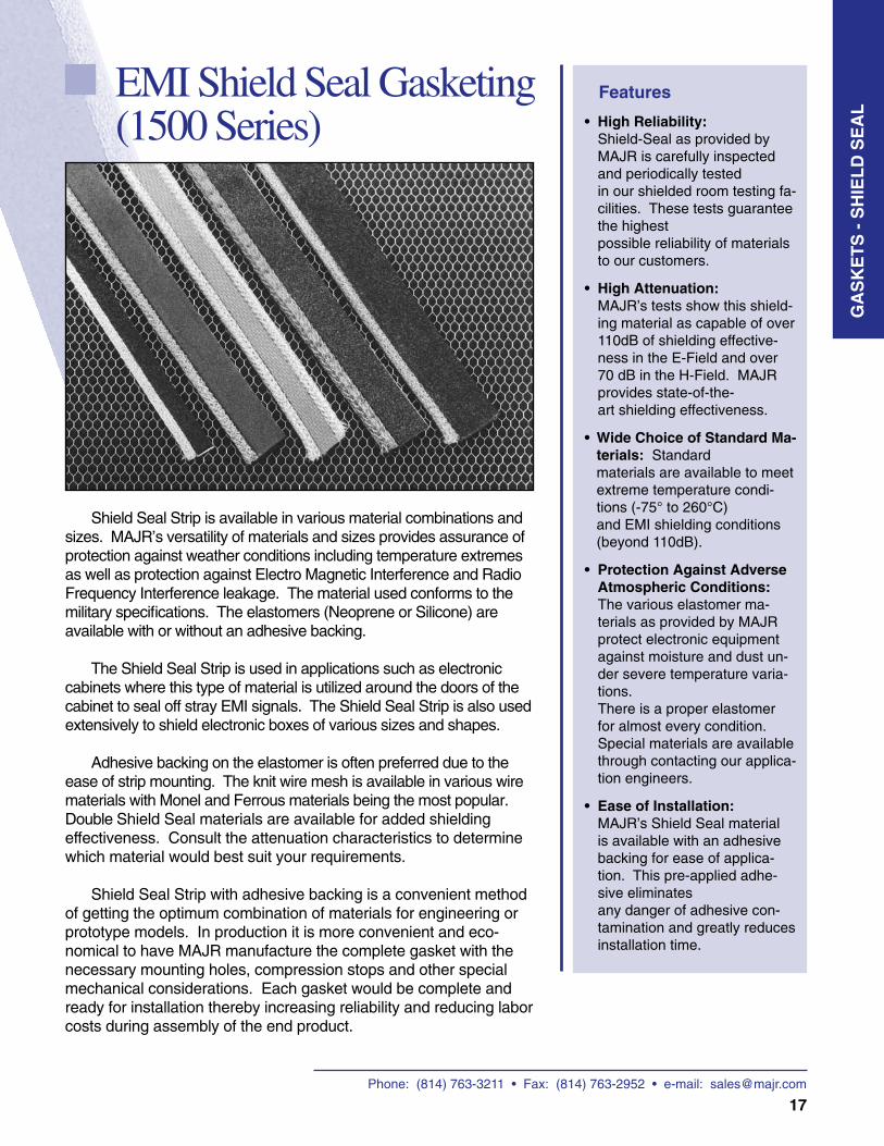
EMI Shield Seal Gasketing (1500 Series)
Features
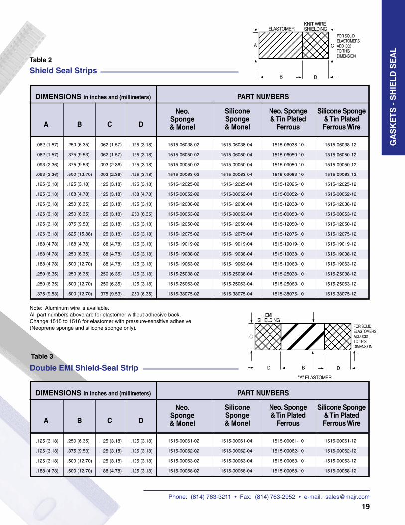
Shield Seal Strip is available in various material combinations and sizes. MAJR’s versatility of materials and sizes provides assurance of protection against weather conditions including temperature extremes as well as protection against Electro Magnetic Interference and Radio Frequency Interference leakage. The material used conforms to the military specifications. The elastomers (Neoprene or Silicone) are available with or without an adhesive backing.
The Shield Seal Strip is used in applications such as electronic cabinets where this type of material is utilized around the doors of the cabinet to seal off stray EMI signals. The Shield Seal Strip is also used extensively to shield electronic boxes of various sizes and shapes.
Adhesive backing on the elastomer is often preferred due to the ease of strip mounting. The knit wire mesh is available in various wire materials with Monel and Ferrous materials being the most popular. Double Shield Seal materials are available for added shielding effectiveness. Consult the attenuation characteristics to determine which material would best suit your requirements.
Shield Seal Strip with adhesive backing is a convenient method of getting the optimum combination of materials for engineering or prototype models. In production it is more convenient and eco-nomical to have MAJR manufacture the complete gasket with the necessary mounting holes, compression stops and other special mechanical considerations. Each gasket would be complete and ready for installation thereby increasing reliability and reducing labor costs during assembly of the end product.
• High Reliability: Shield-Seal as provided by MAJR is carefully inspected and periodically tested in our shielded room testing fa-cilities. These tests guarantee the highest possible reliability of materials to our customers.
• High Attenuation: MAJR’s tests show this shield-ing material as capable of over 110dB of shielding effective-ness in the E-Field and over 70 dB in the H-Field. MAJR provides state-of-the- art shielding effectiveness.
• Wide Choice of Standard Ma-terials: Standard materials are available to meet extreme temperature condi-tions (-75° to 260°C) and EMI shielding conditions (beyond 110dB).
• Protection Against Adverse Atmospheric Conditions: The various elastomer ma-terials as provided by MAJR protect electronic equipment against moisture and dust un-der severe temperature varia-tions. There is a proper elastomer for almost every condition. Special materials are available through contacting our applica-tion engineers.
• Ease of Installation: MAJR’s Shield Seal material is available with an adhesive backing for ease of applica-tion. This pre-applied adhe-sive eliminates any danger of adhesive con-tamination and greatly reduces installation time.
GA
SK
ET
S -
SH
IEL
D S
EA
L
Phone: (814) 763-3211 • Fax: (814) 763-2952 • e-mail: [email protected]
18
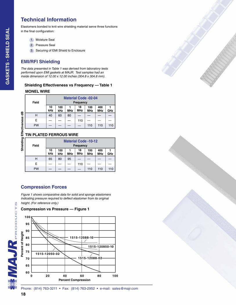
Elastomers bonded to knit wire shielding material serve three functions
in the final configuration:
1. Moisture Seal
2. Pressure Seal
3. Securing of EMI Shield to Enclosure
Technical Information
H
E
PW
40
—
—
60
—
—
80
—
—
—
110
—
FieldMaterial Code -02-04
10 kHz
100 kHz
1 MHz
18 MHz
Sh
ield
ing
Eff
ecti
ven
ess
dB
100 MHz
400 MHz
Frequency
1 GHz
—
—
110
—
—
110
—
—
110
H
E
PW
65
—
—
80
—
—
95
—
—
—
110
—
FieldMaterial Code -10-12
10 kHz
100 kHz
1 MHz
18 MHz
100 MHz
400 MHz
Frequency
1 GHz
—
—
110
—
—
110
—
—
110
EMI/RFI Shielding
Shielding Effectiveness vs Frequency — Table 1
MONEL WIRE
The data presented in Table 1 was derived from laboratory tests performed upon EMI gaskets at MAJR. Test samples had an inside dimension of 12.00 x 12.00 inches (304.8 x 304.8 mm).
TIN PLATED FERROUS WIRE
Compression vs Pressure — Figure 1
Compression Forces
Figure 1 shows comparative data for solid and sponge elastomers indicating pressure required to deflect elastomer from its original
height. (For reference only.)
Percent Compression
GA
SK
ET
S -
SH
IEL
D S
EA
L
Phone: (814) 763-3211 • Fax: (814) 763-2952 • e-mail: [email protected]
19
Neo. Sponge & Tin Plated
FerrousA B C D
DIMENSIONS in inches and (millimeters) PART NUMBERS
Neo. Sponge & Monel
Silicone Sponge & Monel
Silicone Sponge & Tin Plated Ferrous Wire
Shield Seal Strips
.062 (1.57)
.062 (1.57)
.093 (2.36)
.093 (2.36)
.125 (3.18)
.125 (3.18)
.125 (3.18)
.125 (3.18)
.125 (3.18)
.125 (3.18)
.188 (4.78)
.188 (4.78)
.188 (4.78)
.250 (6.35)
.250 (6.35)
.375 (9.53)
.250 (6.35)
.375 (9.53)
.375 (9.53)
.500 (12.70)
.125 (3.18)
.188 (4.78)
.250 (6.35)
.250 (6.35)
.375 (9.53)
.625 (15.88)
.188 (4.78)
.250 (6.35)
.500 (12.70)
.250 (6.35)
.500 (12.70)
.500 (12.70)
.062 (1.57)
.062 (1.57)
.093 (2.36)
.093 (2.36)
.125 (3.18)
.125 (3.18)
.125 (3.18)
.125 (3.18)
.125 (3.18)
.125 (3.18)
.188 (4.78)
.188 (4.78)
.188 (4.78)
.250 (6.35)
.250 (6.35)
.375 (9.53)
.125 (3.18)
.125 (3.18)
.125 (3.18)
.125 (3.18)
.125 (3.18)
.188 (4.78)
.125 (3.18)
.250 (6.35)
.125 (3.18)
.125 (3.18)
.125 (3.18)
.125 (3.18)
.125 (3.18)
.125 (3.18)
.125 (3.18)
.250 (6.35)
1515-06038-02
1515-06050-02
1515-09050-02
1515-09063-02
1515-12025-02
1515-00052-02
1515-12038-02
1515-00053-02
1515-12050-02
1515-12075-02
1515-19019-02
1515-19038-02
1515-19063-02
1515-25038-02
1515-25063-02
1515-38075-02
1515-06038-04
1515-06050-04
1515-09050-04
1515-09063-04
1515-12025-04
1515-00052-04
1515-12038-04
1515-00053-04
1515-12050-04
1515-12075-04
1515-19019-04
1515-19038-04
1515-19063-04
1515-25038-04
1515-25063-04
1515-38075-04
1515-06038-10
1515-06050-10
1515-09050-10
1515-09063-10
1515-12025-10
1515-00052-10
1515-12038-10
1515-00053-10
1515-12050-10
1515-12075-10
1515-19019-10
1515-19038-10
1515-19063-10
1515-25038-10
1515-25063-10
1515-38075-10
1515-06038-12
1515-06050-12
1515-09050-12
1515-09063-12
1515-12025-12
1515-00052-12
1515-12038-12
1515-00053-12
1515-12050-12
1515-12075-12
1515-19019-12
1515-19038-12
1515-19063-12
1515-25038-12
1515-25063-12
1515-38075-12
Note: Aluminum wire is available. All part numbers above are for elastomer without adhesive back. Change 1515 to 1516 for elastomer with pressure-sensitive adhesive (Neoprene sponge and silicone sponge only).
Neo. Sponge & Tin Plated
FerrousA B C D
DIMENSIONS in inches and (millimeters) PART NUMBERS
Neo. Sponge & Monel
Silicone Sponge & Monel
Silicone Sponge & Tin Plated Ferrous Wire
.125 (3.18)
.125 (3.18)
.125 (3.18)
.188 (4.78)
.250 (6.35)
.375 (9.53)
.500 (12.70)
.500 (12.70)
.125 (3.18)
.125 (3.18)
.125 (3.18)
.188 (4.78)
.125 (3.18)
.125 (3.18)
.125 (3.18)
.125 (3.18)
1515-00061-02
1515-00062-02
1515-00063-02
1515-00068-02
1515-00061-04
1515-00062-04
1515-00063-04
1515-00068-04
1515-00061-10
1515-00062-10
1515-00063-10
1515-00068-10
1515-00061-12
1515-00062-12
1515-00063-12
1515-00068-12
Double EMI Shield-Seal Strip
Table 3
Table 2
GA
SK
ET
S -
SH
IEL
D S
EA
L
Phone: (814) 763-3211 • Fax: (814) 763-2952 • e-mail: [email protected]
20
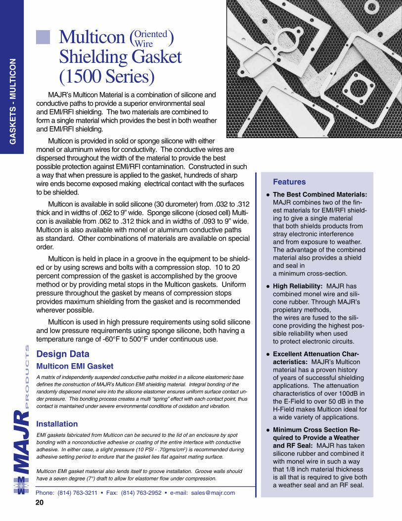
Multicon ( ) Shielding Gasket (1500 Series)
Features
• •
•
•
MAJR’s Multicon Material is a combination of silicone and conductive paths to provide a superior environmental seal and EMI/RFI shielding. The two materials are combined to form a single material which provides the best in both weather and EMI/RFI shielding.
Multicon is provided in solid or sponge silicone with either monel or aluminum wires for conductivity. The conductive wires are dispersed throughout the width of the material to provide the best possible protection against EMI/RFI contamination. Constructed in such a way that when pressure is applied to the gasket, hundreds of sharp wire ends become exposed making electrical contact with the surfaces to be shielded.
Multicon is available in solid silicone (30 durometer) from .032 to .312 thick and in widths of .062 to 9” wide. Sponge silicone (closed cell) Multi-con is available from .062 to .312 thick and in widths of .093 to 9” wide. Multicon is also available with monel or aluminum conductive paths as standard. Other combinations of materials are available on special order.
Multicon is held in place in a groove in the equipment to be shield-ed or by using screws and bolts with a compression stop. 10 to 20 percent compression of the gasket is accomplished by the groove method or by providing metal stops in the Multicon gaskets. Uniform pressure throughout the gasket by means of compression stops provides maximum shielding from the gasket and is recommended wherever possible.
Multicon is used in high pressure requirements using solid silicone and low pressure requirements using sponge silicone, both having a temperature range of -60°F to 500°F under continuous use.
The Best Combined Materials: MAJR combines two of the fin-est materials for EMI/RFI shield-ing to give a single material that both shields products from stray electronic interference and from exposure to weather. The advantage of the combined material also provides a shield and seal in a minimum cross-section.
High Reliability: MAJR has combined monel wire and sili-cone rubber. Through MAJR’s propietary methods, the wires are fused to the sili-cone providing the highest pos-sible reliability when used to protect electronic circuits.
Excellent Attenuation Char-acteristics: MAJR’s Multicon material has a proven history of years of successful shielding applications. The attenuation characteristics of over 100dB in the E-Field to over 50 dB in the H-Field makes Multicon ideal for a wide variety of applications.
Minimum Cross Section Re-quired to Provide a Weather and RF Seal: MAJR has taken silicone rubber and combined it with monel wire in such a way that 1/8 inch material thickness is all that is required to give both a weather seal and an RF seal.
Design Data
A matrix of independently suspended conductive paths molded in a silicone elastomeric base defines the construction of MAJR’s Multicon EMI shielding material. Integral bonding of the randomly dispersed monel wire into the silicone elastomer ensures uniform surface contact un-der pressure. This bonding process creates a multi “spring” effect with each contact point, thus contact is maintained under severe environmental conditions of oxidation and vibration.
EMI gaskets fabricated from Multicon can be secured to the lid of an enclosure by spot bonding with a nonconductive adhesive or coating of the entire interface with conductive adhesive. In either case, a slight pressure (10 PSI - .70gms/cm2) is recommended during adhesive setting period to endure that the gasket lies flat against mating surface.
Multicon EMI gasket material also lends itself to groove installation. Groove walls should have a seven degree (7°) draft to allow for elastomer flow under compression.
Installation
Multicon EMI Gasket
GA
SK
ET
S -
MU
LTIC
ON
Oriented Wire
Phone: (814) 763-3211 • Fax: (814) 763-2952 • e-mail: [email protected]
21
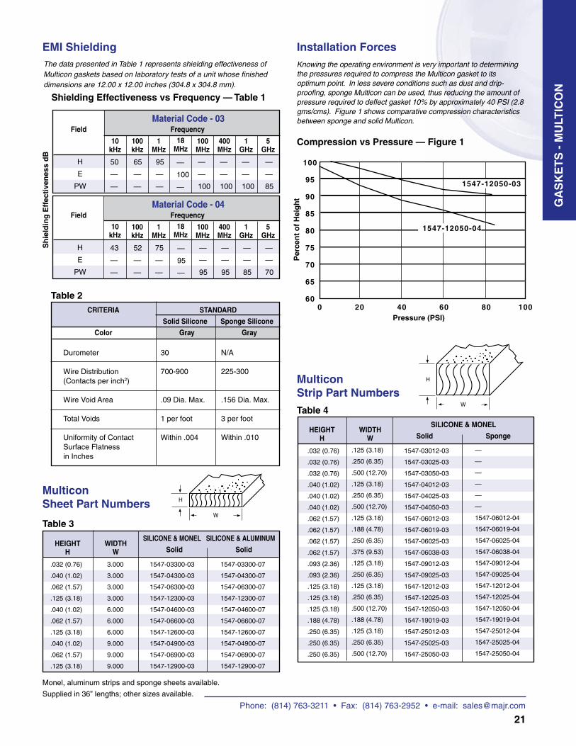
EMI ShieldingThe data presented in Table 1 represents shielding effectiveness of Multicon gaskets based on laboratory tests of a unit whose finished dimensions are 12.00 x 12.00 inches (304.8 x 304.8 mm).
H
E
PW
50
—
—
65
—
—
95
—
—
—
100
—
FieldMaterial Code - 03
10 kHz
100 kHz
1 MHz
18 MHz
Sh
ield
ing
Eff
ecti
ven
ess
dB
100 MHz
400 MHz
Frequency
1 GHz
—
—
100
—
—
100
—
—
100
H
E
PW
43
—
—
52
—
—
75
—
—
—
95
—
FieldMaterial Code - 04
10 kHz
100 kHz
1 MHz
18 MHz
100 MHz
400 MHz
Frequency
1 GHz
—
—
95
—
—
95
—
—
85
Shielding Effectiveness vs Frequency — Table 1
Installation ForcesKnowing the operating environment is very important to determining the pressures required to compress the Multicon gasket to its optimum point. In less severe conditions such as dust and drip- proofing, sponge Multicon can be used, thus reducing the amount of pressure required to deflect gasket 10% by approximately 40 PSI (2.8 gms/cms). Figure 1 shows comparative compression characteristics between sponge and solid Multicon.
Compression vs Pressure — Figure 1
HEIGHT H
WIDTH W
SILICONE & MONEL
Solid Sponge
Multicon Strip Part Numbers
Multicon Sheet Part Numbers
HEIGHT H
WIDTH W
SILICONE & MONEL SILICONE & ALUMINUM
Solid Solid
.032 (0.76)
.040 (1.02)
.062 (1.57)
.125 (3.18)
.040 (1.02)
.062 (1.57)
.125 (3.18)
.040 (1.02)
.062 (1.57)
.125 (3.18)
3.000
3.000
3.000
3.000
6.000
6.000
6.000
9.000
9.000
9.000
1547-03300-03
1547-04300-03
1547-06300-03
1547-12300-03
1547-04600-03
1547-06600-03
1547-12600-03
1547-04900-03
1547-06900-03
1547-12900-03
1547-03300-07
1547-04300-07
1547-06300-07
1547-12300-07
1547-04600-07
1547-06600-07
1547-12600-07
1547-04900-07
1547-06900-07
1547-12900-07
Table 4
Table 3
Monel, aluminum strips and sponge sheets available.
Supplied in 36” lengths; other sizes available.
Durometer
Wire Distribution(Contacts per inch2)
Wire Void Area
Total Voids
Uniformity of ContactSurface Flatnessin Inches
Table 2CRITERIA
Color
STANDARD
Solid Silicone Sponge Silicone
Gray Gray
30
700-900
.09 Dia. Max.
1 per foot
Within .004
N/A
225-300
.156 Dia. Max.
3 per foot
Within .010
.032 (0.76)
.032 (0.76)
.032 (0.76)
.040 (1.02)
.040 (1.02)
.040 (1.02)
.062 (1.57)
.062 (1.57)
.062 (1.57)
.062 (1.57)
.093 (2.36)
.093 (2.36)
.125 (3.18)
.125 (3.18)
.125 (3.18)
.188 (4.78)
.250 (6.35)
.250 (6.35)
.250 (6.35)
.125 (3.18)
.250 (6.35)
.500 (12.70)
.125 (3.18)
.250 (6.35)
.500 (12.70)
.125 (3.18)
.188 (4.78)
.250 (6.35)
.375 (9.53)
.125 (3.18)
.250 (6.35)
.125 (3.18)
.250 (6.35)
.500 (12.70)
.188 (4.78)
.125 (3.18)
.250 (6.35)
.500 (12.70)
1547-03012-03
1547-03025-03
1547-03050-03
1547-04012-03
1547-04025-03
1547-04050-03
1547-06012-03
1547-06019-03
1547-06025-03
1547-06038-03
1547-09012-03
1547-09025-03
1547-12012-03
1547-12025-03
1547-12050-03
1547-19019-03
1547-25012-03
1547-25025-03
1547-25050-03
—
—
—
—
—
—
1547-06012-04
1547-06019-04
1547-06025-04
1547-06038-04
1547-09012-04
1547-09025-04
1547-12012-04
1547-12025-04
1547-12050-04
1547-19019-04
1547-25012-04
1547-25025-04
1547-25050-04
5 GHz
—
—
85
5 GHz
—
—
70
GA
SK
ET
S -
MU
LTIC
ON
Phone: (814) 763-3211 • Fax: (814) 763-2952 • e-mail: [email protected]
22
EMI/RFI Gaskets for Connectors (2000 Series)
Features
• • • •
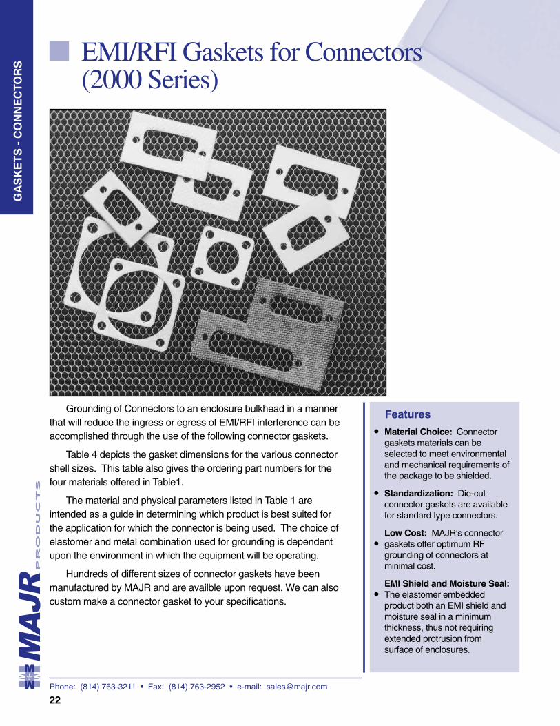
Grounding of Connectors to an enclosure bulkhead in a manner that will reduce the ingress or egress of EMI/RFI interference can be accomplished through the use of the following connector gaskets.
Table 4 depicts the gasket dimensions for the various connector shell sizes. This table also gives the ordering part numbers for the four materials offered in Table1.
The material and physical parameters listed in Table 1 are intended as a guide in determining which product is best suited for the application for which the connector is being used. The choice of elastomer and metal combination used for grounding is dependent upon the environment in which the equipment will be operating.
Hundreds of different sizes of connector gaskets have been manufactured by MAJR and are availble upon request. We can also custom make a connector gasket to your specifications.
Material Choice: Connector gaskets materials can be selected to meet environmental and mechanical requirements of the package to be shielded.
Standardization: Die-cut connector gaskets are available for standard type connectors.
Low Cost: MAJR’s connector gaskets offer optimum RF grounding of connectors at minimal cost.
EMI Shield and Moisture Seal: The elastomer embedded product both an EMI shield and moisture seal in a minimum thickness, thus not requiring extended protrusion from surface of enclosures.
GA
SK
ET
S -
CO
NN
EC
TOR
S
Phone: (814) 763-3211 • Fax: (814) 763-2952 • e-mail: [email protected]
23
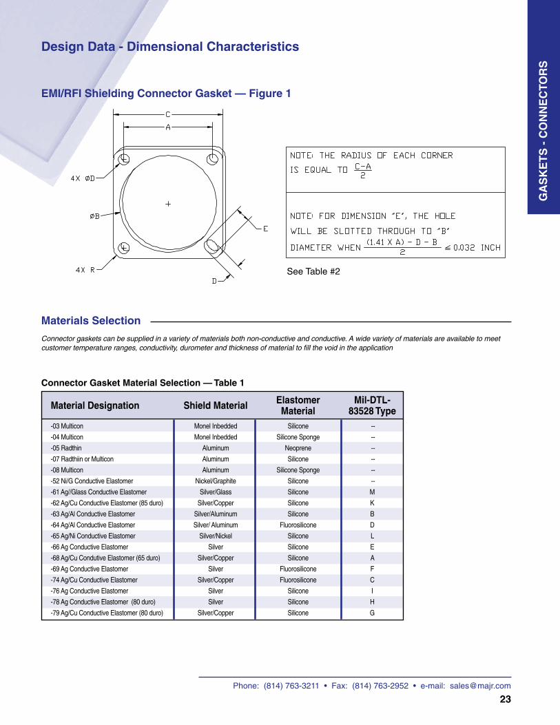
Design Data - Dimensional Characteristics
EMI/RFI Shielding Connector Gasket — Figure 1
Connector Gasket Material Selection — Table 1
Connector gaskets can be supplied in a variety of materials both non-conductive and conductive. A wide variety of materials are available to meet customer temperature ranges, conductivity, durometer and thickness of material to fill the void in the application
Materials Selection
GA
SK
ET
S -
CO
NN
EC
TOR
S
See Table #2
Material Designation Shield Material Elastomer Mil-DTL- Material 83528 Type-03 Multicon Monel Inbedded Silicone --
-04 Multicon Monel Inbedded Silicone Sponge --
-05 Radthin Aluminum Neoprene --
-07 Radthiin or Multicon Aluminum Silicone --
-08 Multicon Aluminum Silicone Sponge --
-52 Ni/G Conductive Elastomer Nickel/Graphite Silicone --
-61 Ag//Glass Conductive Elastomer Silver/Glass Silicone M
-62 Ag/Cu Conductive Elastomer (85 duro) Silver/Copper Silicone K
-63 Ag/Al Conductive Elastomer Silver/Aluminum Silicone B
-64 Ag/Al Conductive Elastomer Silver/ Aluminum Fluorosilicone D
-65 Ag/Ni Conductive Elastomer Silver/Nickel Silicone L
-66 Ag Conductive Elastomer Silver Silicone E
-68 Ag/Cu Condutive Elastomer (65 duro) Silver/Copper Silicone A
-69 Ag Conductive Elastomer Silver Fluorosilicone F
-74 Ag/Cu Conductive Elastomer Silver/Copper Fluorosilicone C
-76 Ag Conductive Elastomer Silver Silicone I
-78 Ag Conductive Elastomer (80 duro) Silver Silicone H
-79 Ag/Cu Conductive Elastomer (80 duro) Silver/Copper Silicone G
Phone: (814) 763-3211 • Fax: (814) 763-2952 • e-mail: [email protected]
24
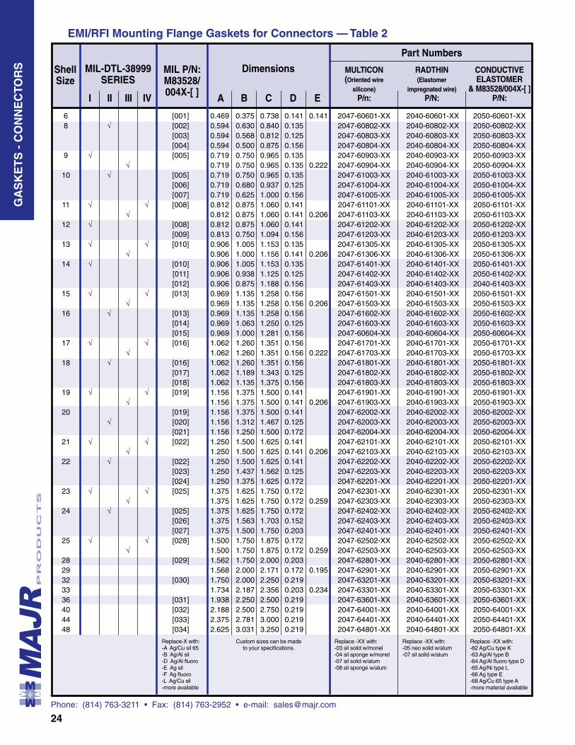
A B C D E I II III IV
Shell Size
DimensionsMIL-DTL-38999 SERIES
MIL P/N: M83528/ 004X-[ ]
EMI/RFI Mounting Flange Gaskets for Connectors — Table 2
MULTICON RADTHIN CONDUCTIVE (Oriented wire (Elastomer ELASTOMER silicone) impregnated wire) & M83528/004X-[ ] P/n: P/N: P/N:
6 [001] 0.469 0.375 0.738 0.141 0.141 2047-60601-XX 2040-60601-XX 2050-60601-XX 8 √ [002] 0.594 0.630 0.840 0.135 2047-60802-XX 2040-60802-XX 2050-60802-XX [003] 0.594 0.568 0.812 0.125 2047-60803-XX 2040-60803-XX 2050-60803-XX [004] 0.594 0.500 0.875 0.156 2047-60804-XX 2040-60804-XX 2050-60804-XX 9 √ [005] 0.719 0.750 0.965 0.135 2047-60903-XX 2040-60903-XX 2050-60903-XX √ 0.719 0.750 0.965 0.135 0.222 2047-60904-XX 2040-60904-XX 2050-60904-XX 10 √ [005] 0.719 0.750 0.965 0.135 2047-61003-XX 2040-61003-XX 2050-61003-XX [006] 0.719 0.680 0.937 0.125 2047-61004-XX 2040-61004-XX 2050-61004-XX [007] 0.719 0.625 1.000 0.156 2047-61005-XX 2040-61005-XX 2050-61005-XX 11 √ √ [008] 0.812 0.875 1.060 0.141 2047-61101-XX 2040-61101-XX 2050-61101-XX √ 0.812 0.875 1.060 0.141 0.206 2047-61103-XX 2040-61103-XX 2050-61103-XX 12 √ [008] 0.812 0.875 1.060 0.141 2047-61202-XX 2040-61202-XX 2050-61202-XX [009] 0.813 0.750 1.094 0.156 2047-61203-XX 2040-61203-XX 2050-61203-XX 13 √ √ [010] 0.906 1.005 1.153 0.135 2047-61305-XX 2040-61305-XX 2050-61305-XX √ 0.906 1.000 1.156 0.141 0.206 2047-61306-XX 2040-61306-XX 2050-61306-XX 14 √ [010] 0.906 1.005 1.153 0.135 2047-61401-XX 2040-61401-XX 2050-61401-XX [011] 0.906 0.938 1.125 0.125 2047-61402-XX 2040-61402-XX 2050-61402-XX [012] 0.906 0.875 1.188 0.156 2047-61403-XX 2040-61403-XX 2040-61403-XX 15 √ √ [013] 0.969 1.135 1.258 0.156 2047-61501-XX 2040-61501-XX 2050-61501-XX √ 0.969 1.135 1.258 0.156 0.206 2047-61503-XX 2040-61503-XX 2050-61503-XX 16 √ [013] 0.969 1.135 1.258 0.156 2047-61602-XX 2040-61602-XX 2050-61602-XX [014] 0.969 1.063 1.250 0.125 2047-61603-XX 2040-61603-XX 2050-61603-XX [015] 0.969 1.000 1.281 0.156 2047-60604-XX 2040-60604-XX 2050-60604-XX 17 √ √ [016] 1.062 1.260 1.351 0.156 2047-61701-XX 2040-61701-XX 2050-61701-XX √ 1.062 1.260 1.351 0.156 0.222 2047-61703-XX 2040-61703-XX 2050-61703-XX 18 √ [016] 1.062 1.260 1.351 0.156 2047-61801-XX 2040-61801-XX 2050-61801-XX [017] 1.062 1.189 1.343 0.125 2047-61802-XX 2040-61802-XX 2050-61802-XX [018] 1.062 1.135 1.375 0.156 2047-61803-XX 2040-61803-XX 2050-61803-XX 19 √ √ [019] 1.156 1.375 1.500 0.141 2047-61901-XX 2040-61901-XX 2050-61901-XX √ 1.156 1.375 1.500 0.141 0.206 2047-61903-XX 2040-61903-XX 2050-61903-XX 20 [019] 1.156 1.375 1.500 0.141 2047-62002-XX 2040-62002-XX 2050-62002-XX √ [020] 1.156 1.312 1.467 0.125 2047-62003-XX 2040-62003-XX 2050-62003-XX [021] 1.156 1.250 1.500 0.172 2047-62004-XX 2040-62004-XX 2050-62004-XX 21 √ √ [022] 1.250 1.500 1.625 0.141 2047-62101-XX 2040-62101-XX 2050-62101-XX √ 1.250 1.500 1.625 0.141 0.206 2047-62103-XX 2040-62103-XX 2050-62103-XX 22 √ [022] 1.250 1.500 1.625 0.141 2047-62202-XX 2040-62202-XX 2050-62202-XX [023] 1.250 1.437 1.562 0.125 2047-62203-XX 2040-62203-XX 2050-62203-XX [024] 1.250 1.375 1.625 0.172 2047-62201-XX 2040-62201-XX 2050-62201-XX 23 √ √ [025] 1.375 1.625 1.750 0.172 2047-62301-XX 2040-62301-XX 2050-62301-XX √ 1.375 1.625 1.750 0.172 0.259 2047-62303-XX 2040-62303-XX 2050-62303-XX 24 √ [025] 1.375 1.625 1.750 0.172 2047-62402-XX 2040-62402-XX 2050-62402-XX [026] 1.375 1.563 1.703 0.152 2047-62403-XX 2040-62403-XX 2050-62403-XX [027] 1.375 1.500 1.750 0.203 2047-62401-XX 2040-62401-XX 2050-62401-XX 25 √ √ [028] 1.500 1.750 1.875 0.172 2047-62502-XX 2040-62502-XX 2050-62502-XX √ 1.500 1.750 1.875 0.172 0.259 2047-62503-XX 2040-62503-XX 2050-62503-XX 28 [029] 1.562 1.750 2.000 0.203 2047-62801-XX 2040-62801-XX 2050-62801-XX 29 1.568 2.000 2.171 0.172 0.195 2047-62901-XX 2040-62901-XX 2050-62901-XX 32 [030] 1.750 2.000 2.250 0.219 2047-63201-XX 2040-63201-XX 2050-63201-XX 33 1.734 2.187 2.356 0.203 0.234 2047-63301-XX 2040-63301-XX 2050-63301-XX 36 [031] 1.938 2.250 2.500 0.219 2047-63601-XX 2040-63601-XX 2050-63601-XX 40 [032] 2.188 2.500 2.750 0.219 2047-64001-XX 2040-64001-XX 2050-64001-XX 44 [033] 2.375 2.781 3.000 0.219 2047-64401-XX 2040-64401-XX 2050-64401-XX 48 [034] 2.625 3.031 3.250 0.219 2047-64801-XX 2040-64801-XX 2050-64801-XX
GA
SK
ET
S -
CO
NN
EC
TOR
S
Part Numbers
Replace-X with:-A Ag/Cu sil 65-B Ag/Al sil-D Ag/Al fluoro-E Ag sil-F Ag fluoro-L Ag/Cu sil-more available
Custom sizes can be made to your specifications.
Replace -XX with:-03 sil solid w/monel-04 sil sponge w/monel-07 sil solid w/alum-08 sil sponge w/alum
Replace -XX with:-05 neo solid w/alum-07 sil solid w/alum
Replace -XX with:-62 Ag/Cu type K-63 Ag/Al type B-64 Ag/Al fluoro type D-65 Ag/Ni type L-66 Ag type E-68 Ag/Cu 65 type A-more material available
Phone: (814) 763-3211 • Fax: (814) 763-2952 • e-mail: [email protected]
25
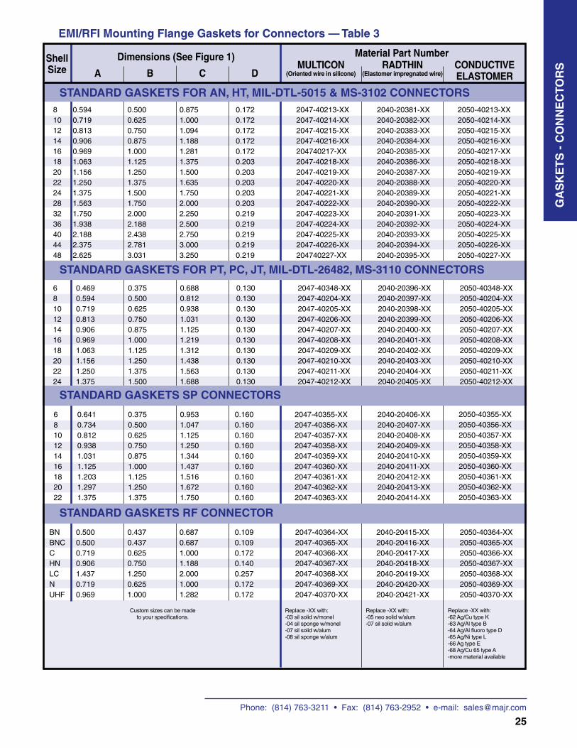
A B C D
EMI/RFI Mounting Flange Gaskets for Connectors — Table 3
Shell Size
Dimensions (See Figure 1) Material Part Number
81012141618202224283236404448
0.5940.7190.8130.9060.9691.0631.1561.2501.3751.5631.7501.9382.1882.3752.625
0.5000.6250.7500.8751.0001.1251.2501.3751.5001.7502.0002.1882.4382.7813.031
0.8751.0001.0941.1881.2811.3751.5001.6351.7502.0002.2502.5002.7503.0003.250
0.1720.1720.1720.1720.1720.2030.2030.2030.2030.2030.2190.2190.2190.2190.219
2047-40213-XX2047-40214-XX2047-40215-XX2047-40216-XX204740217-XX2047-40218-XX2047-40219-XX2047-40220-XX2047-40221-XX2047-40222-XX2047-40223-XX2047-40224-XX2047-40225-XX2047-40226-XX204740227-XX
2040-20381-XX2040-20382-XX2040-20383-XX2040-20384-XX2040-20385-XX2040-20386-XX2040-20387-XX2040-20388-XX2040-20389-XX2040-20390-XX2040-20391-XX2040-20392-XX2040-20393-XX2040-20394-XX2040-20395-XX
2050-40213-XX2050-40214-XX2050-40215-XX2050-40216-XX2050-40217-XX2050-40218-XX2050-40219-XX2050-40220-XX2050-40221-XX2050-40222-XX2050-40223-XX2050-40224-XX2050-40225-XX2050-40226-XX2050-40227-XX
681012141618202224
0.4690.5940.7190.8130.9060.9691.0631.1561.2501.375
0.3750.5000.6250.7500.8751.0001.1251.2501.3751.500
0.6880.8120.9381.0311.1251.2191.3121.4381.5631.688
0.1300.1300.1300.1300.1300.1300.1300.1300.1300.130
2047-40348-XX2047-40204-XX2047-40205-XX2047-40206-XX2047-40207-XX2047-40208-XX2047-40209-XX2047-40210-XX2047-40211-XX2047-40212-XX
2040-20396-XX2040-20397-XX2040-20398-XX2040-20399-XX2040-20400-XX2040-20401-XX2040-20402-XX2040-20403-XX2040-20404-XX2040-20405-XX
2050-40348-XX2050-40204-XX2050-40205-XX2050-40206-XX2050-40207-XX2050-40208-XX2050-40209-XX2050-40210-XX2050-40211-XX2050-40212-XX
6810121416182022
0.6410.7340.8120.9381.0311.1251.2031.2971.375
0.3750.5000.6250.7500.8751.0001.1251.2501.375
0.9531.0471.1251.2501.3441.4371.5161.6721.750
0.1600.1600.1600.1600.1600.1600.1600.1600.160
2047-40355-XX2047-40356-XX2047-40357-XX2047-40358-XX2047-40359-XX2047-40360-XX2047-40361-XX2047-40362-XX2047-40363-XX
2040-20406-XX2040-20407-XX2040-20408-XX2040-20409-XX2040-20410-XX2040-20411-XX2040-20412-XX2040-20413-XX2040-20414-XX
2050-40355-XX2050-40356-XX2050-40357-XX2050-40358-XX2050-40359-XX2050-40360-XX2050-40361-XX2050-40362-XX2050-40363-XX
BNBNCCHNLCNUHF
0.5000.5000.7190.9061.4370.7190.969
0.4370.4370.6250.7501.2500.6251.000
0.6870.6871.0001.1882.0001.0001.282
0.1090.1090.1720.1400.2570.1720.172
2047-40364-XX2047-40365-XX2047-40366-XX2047-40367-XX2047-40368-XX2047-40369-XX2047-40370-XX
2040-20415-XX2040-20416-XX2040-20417-XX2040-20418-XX2040-20419-XX2040-20420-XX2040-20421-XX
2050-40364-XX2050-40365-XX2050-40366-XX2050-40367-XX2050-40368-XX2050-40369-XX2050-40370-XX
STANDARD GASKETS FOR AN, HT, MIL-DTL-5015 & MS-3102 CONNECTORS
STANDARD GASKETS FOR PT, PC, JT, MIL-DTL-26482, MS-3110 CONNECTORS
STANDARD GASKETS SP CONNECTORS
STANDARD GASKETS RF CONNECTOR
GA
SK
ET
S -
CO
NN
EC
TOR
SMULTICON (Oriented wire in silicone)
RADTHIN(Elastomer impregnated wire)
CONDUCTIVE ELASTOMER
Replace -XX with:-62 Ag/Cu type K-63 Ag/Al type B-64 Ag/Al fluoro type D-65 Ag/Ni type L-66 Ag type E-68 Ag/Cu 65 type A-more material available
Replace -XX with:-05 neo solid w/alum-07 sil solid w/alum
Replace -XX with:-03 sil solid w/monel-04 sil sponge w/monel-07 sil solid w/alum-08 sil sponge w/alum
Custom sizes can be made to your specifications.
Phone: (814) 763-3211 • Fax: (814) 763-2952 • e-mail: [email protected]
26
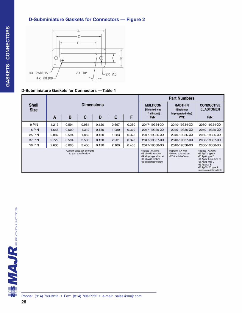
9 PIN 1.213 0.594 0.984 0.120 0.697 0.360 2047-19334-XX 2040-19334-XX 2050-19334-XX
15 PIN 1.556 0.600 1.312 0.130 1.080 0.370 2047-19335-XX 2040-19335-XX 2050-19335-XX
25 PIN 2.087 0.594 1.852 0.120 1.583 0.378 2047-19336-XX 2040-19336-XX 2050-19336-XX
37 PIN 2.729 0.594 2.500 0.120 2.231 0.378 2047-19337-XX 2040-19337-XX 2050-19337-XX
50 PIN 2.635 0.605 2.406 0.120 2.109 0.466 2047-19338-XX 2040-19338-XX 2050-19338-XX
GA
SK
ET
S -
CO
NN
EC
TOR
S
A B C D E F
Shell Size
Dimensions MULTICON RADTHIN CONDUCTIVE (Oriented wire (Elastomer ELASTOMER in silicone) impregnated wire) P/N: P/N: P/N:
Part Numbers
Custom sizes can be made to your specifications.
Replace -XX with:-03 sil solid w/monel-04 sil sponge w/monel-07 sil solid w/alum-08 sil sponge w/alum
Replace -XX with:-05 neo solid w/alum-07 sil solid w/alum
Replace -XX with:-62 Ag/Cu type K-63 Ag/Al type B-64 Ag/Al fluoro type D-65 Ag/Ni type L-66 Ag type E-68 Ag/Cu 65 type A-more material available
D-Subminiature Gaskets for Connectors — Figure 2
D-Subminiature Gaskets for Connectors — Table 4
Phone: (814) 763-3211 • Fax: (814) 763-2952 • e-mail: [email protected]
27
EMI/RFI Grounding Washers (2500 Series)
Features
•
•
•
•
Design Data
Applications
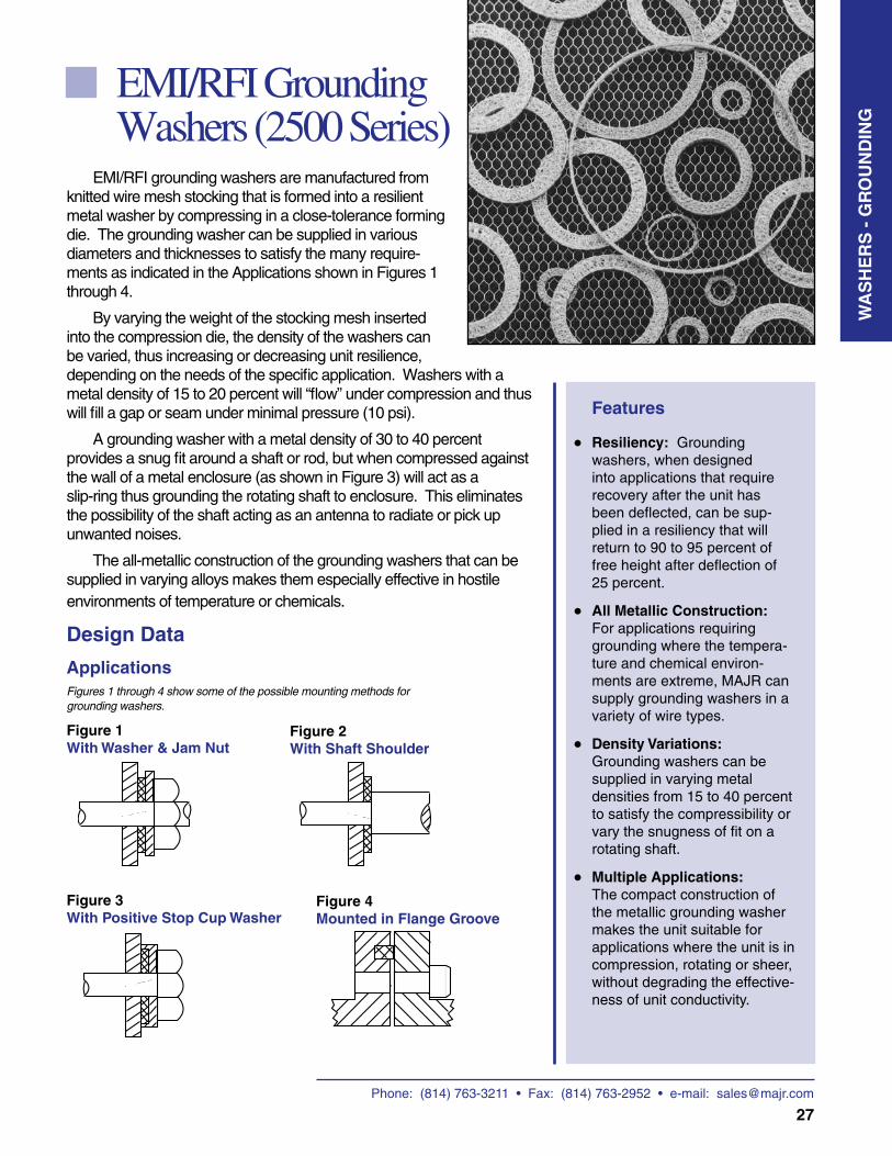
Figure 1With Washer & Jam Nut
EMI/RFI grounding washers are manufactured from knitted wire mesh stocking that is formed into a resilient metal washer by compressing in a close-tolerance forming die. The grounding washer can be supplied in various diameters and thicknesses to satisfy the many require- ments as indicated in the Applications shown in Figures 1 through 4.
By varying the weight of the stocking mesh inserted into the compression die, the density of the washers can be varied, thus increasing or decreasing unit resilience, depending on the needs of the specific application. Washers with a metal density of 15 to 20 percent will “flow” under compression and thus will fill a gap or seam under minimal pressure (10 psi).
A grounding washer with a metal density of 30 to 40 percent provides a snug fit around a shaft or rod, but when compressed against the wall of a metal enclosure (as shown in Figure 3) will act as a slip-ring thus grounding the rotating shaft to enclosure. This eliminates the possibility of the shaft acting as an antenna to radiate or pick up unwanted noises.
The all-metallic construction of the grounding washers that can be supplied in varying alloys makes them especially effective in hostile environments of temperature or chemicals.
Resiliency: Grounding washers, when designed into applications that require recovery after the unit has been deflected, can be sup-plied in a resiliency that will return to 90 to 95 percent of free height after deflection of 25 percent.
All Metallic Construction: For applications requiring grounding where the tempera- ture and chemical environ-ments are extreme, MAJR can supply grounding washers in a variety of wire types.
Density Variations: Grounding washers can be supplied in varying metal densities from 15 to 40 percent to satisfy the compressibility or vary the snugness of fit on a rotating shaft.
Multiple Applications: The compact construction of the metallic grounding washer makes the unit suitable for applications where the unit is in compression, rotating or sheer, without degrading the effective-ness of unit conductivity.
Figures 1 through 4 show some of the possible mounting methods for grounding washers.
Figure 2With Shaft Shoulder
Figure 3With Positive Stop Cup Washer
WA
SH
ER
S -
GR
OU
ND
ING
Figure 4Mounted in Flange Groove

Phone: (814) 763-3211 • Fax: (814) 763-2952 • e-mail: [email protected]
28
Available Sizes
Table 2 shows washer sizes that can readily be supplied from existing tooling. Thickness can be varied from .032 to .125.
Table 1 — Grounding Washer Diameters
Part Number O.D. I.D.
Up to 1 (Up to 25.40)
1 to 2 (25.40 to 50.80)
2 to 3 (50.80 to 76.20)
3 to 4 (76.20 to 101.60)
Over 4 (101.60)
Tolerances
+0.015, -0.000 (+0.38)
+0.020, -0.000 (+0.51)
+0.025, -0.000 (+0.63)
+0.030, -0.000 (+0.76)
+0.040, -0.000 (+1.02)
+0.000, -0.015 (-0.38)
+0.000, -0.020 (-0.51)
+0.000, -0.025 (-0.63)
+0.000, -0.030, (-0.76)
+0.000. -0.040 (-1.02)
Sizes O.D. I.D.
Table 2
Materials
Grounding washers can be supplied using knit wire mesh of the following materials:
Code Description
Table 3
Monel per QQ-N-281 Class A
Aluminum
Silver Plated Brass per QQ-W-321 (3% Silver by Weight)
Tin Plated Copper Clad Steel per ASTM B520
-31
-32
-33
-34
* xx: See Table 3 for material codes. A = Thickness. Thickness needs to be specified at time of request or order.
250A-70005-xx 0.218 0.062250A-70007-xx 0.375 0.250250A-70010-xx 1.000 0.500250A-70015-xx 0.234 0.109250A-70020-xx 0.500 0.250250A-70027-xx 0.635 0.500250A-70076-xx 1.120 0.810250A-70079-xx 2.322 2.202250A-70084-xx 1.370 1.120250A-70094-xx 0.062 0.000250A-70106-xx 1.425 1.043250A-70108-xx 1.437 1.063250A-70109-xx 1.437 1.083250A-70110-xx 1.437 1.102250A-70115-xx 0.255 0.150250A-70117-xx 0.885 0.625250A-70118-xx 0.630 0.550250A-70119-xx 1.380 1.250250A-70120-xx 0.320 0.260250A-70121-xx 0.880 0.810250A-70122-xx 0.635 0.375250A-70134-xx 0.937 0.687250A-70135-xx 0.625 0.469250A-70136-xx 1.620 1.125250A-70137-xx 2.130 1.600250A-70138-xx 0.495 0.295250A-70144-xx 0.875 0.375250A-70145-xx 0.345 0.185250A-70150-xx 2.125 1.812250A-70158-xx 1.500 1.000250A-70160-xx 2.950 2.875250A-70170-xx 2.642 2.562250A-70180-xx 0.910 0.790250A-70200-xx 0.750 0.250250A-70300-xx 0.225 0.130250A-70310-xx 0.410 0.250250A-70320-xx 0.350 0.175250A-70350-xx 0.906 0.344250A-70360-xx 0.550 0.200250A-70500-xx 0.875 0.344250A-70501-xx 0.875 0.315250A-70502-xx 0.275 0.180250A-70503-xx 0.300 0.150250A-70504-xx 0.240 0.187250A-70505-xx 1.688 0.250250A-70507-xx 1.812 1.562250A-70508-xx 0.600 0.438250A-70509-xx 0.500 0.375250A-70510-xx 0.800 0.650250A-70511-xx 2.835 2.047250A-70512-xx 3.543 2.632250A-70513-xx 0.300 0.187250A-70514-xx 0.755 0.630250A-70515-xx 2.000 1.000250A-70516-xx 0.305 0.248250A-70517-xx 2.180 2.060250A-70518-xx 0.750 0.500250A-70600-xx 1.370 0.750250A-70650-xx 2.625 0.450250A-70700-xx 0.500 0.200250A-70710-xx 0.450 0.170250A-70720-xx 1.250 0.315250A-70730-xx 1.880 0.680250A-70740-xx 1.000 0.300250A-70750-xx 1.800 0.480250A-70755-xx 1.100 0.315250A-70756-xx 0.900 0.480250A-70800-xx 0.394 0.323250A-70950-xx 1.375 1.125
WA
SH
ER
S -
GR
OU
ND
ING
Phone: (814) 763-3211 • Fax: (814) 763-2952 • e-mail: [email protected]
Phone: (814) 763-3211 • Fax: (814) 763-2952 • e-mail: [email protected]
29
Color Copper Silver Silver
Tempurature 155 degress C — -40 C to +110 C Resistance
Resistivity through 10 milliohms/square inch 40 milliohms/square inch 50 milliohms/square inch Adhesive
Elongation at Break 4% 5% —
Backing .0014” (1oz) Copper Foil .0018” Aluminum Foil 0.003” conductive fabric
Adhesive Conductive Acrylic Conductive Acrylic —
Inter Liner Polyethelene Coated Paper Line — —
Adhesive (thickness) — — .002”
Peel Strength 35 oz./inch of width 35 oz./inch of width 51 oz./inch of width
Breaking Strength 25 lbs./inch of width 15 lbs./inch of width —
RFI attenuation — — 90 – 100 dB from 20 MHz to 10 GHz
Tape Dimensions (Max) — — Width 1000mm, Length 100 M
EMI Shielding Tape with Conductive Adhesive (2800 Series)
• • • • •••
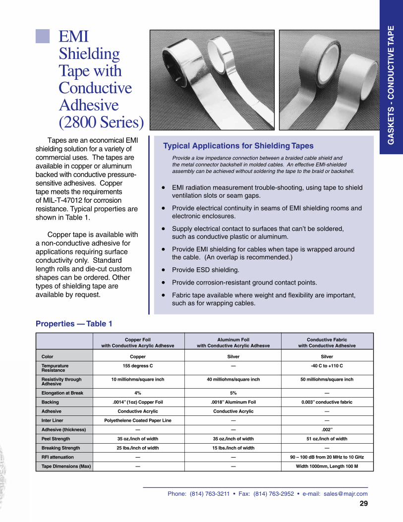
EMI radiation measurement trouble-shooting, using tape to shield ventilation slots or seam gaps.
Provide electrical continuity in seams of EMI shielding rooms and electronic enclosures.
Supply electrical contact to surfaces that can’t be soldered, such as conductive plastic or aluminum.
Provide EMI shielding for cables when tape is wrapped around the cable. (An overlap is recommended.)
Provide ESD shielding.
Provide corrosion-resistant ground contact points.
Fabric tape available where weight and flexibility are important, such as for wrapping cables.
Provide a low impedance connection between a braided cable shield and the metal connector backshell in molded cables. An effective EMI-shielded assembly can be achieved without soldering the tape to the braid or backshell.
Typical Applications for Shielding TapesTapes are an economical EMI
shielding solution for a variety of commercial uses. The tapes are available in copper or aluminum backed with conductive pressure-sensitive adhesives. Copper tape meets the requirements of MIL-T-47012 for corrosion resistance. Typical properties are shown in Table 1.
Copper tape is available with a non-conductive adhesive for applications requiring surface conductivity only. Standard length rolls and die-cut custom shapes can be ordered. Other types of shielding tape are available by request.
Properties — Table 1
GA
SK
ET
S -
CO
ND
UC
TIV
E T
AP
E
Copper Foil Aluminum Foil Conductive Fabric with Conductive Acrylic Adhesve with Conductive Acrylic Adhesve with Conductive Adhesive
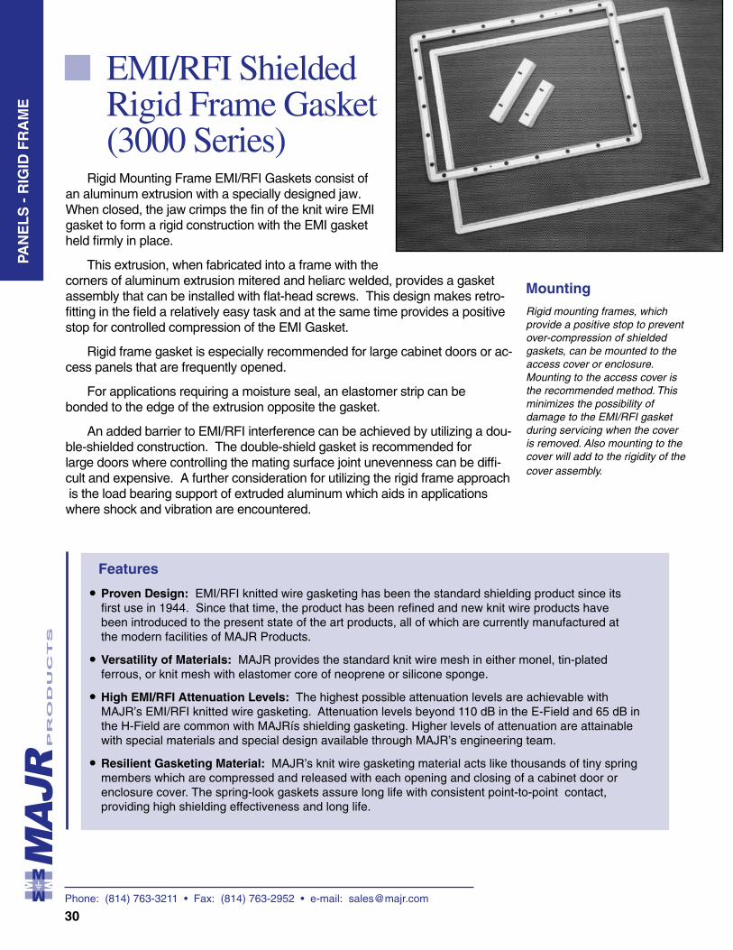
Phone: (814) 763-3211 • Fax: (814) 763-2952 • e-mail: [email protected]
30
EMI/RFI Shielded Rigid Frame Gasket (3000 Series)
Features
• • • •
Proven Design: EMI/RFI knitted wire gasketing has been the standard shielding product since its first use in 1944. Since that time, the product has been refined and new knit wire products have been introduced to the present state of the art products, all of which are currently manufactured at the modern facilities of MAJR Products.
Versatility of Materials: MAJR provides the standard knit wire mesh in either monel, tin-plated ferrous, or knit mesh with elastomer core of neoprene or silicone sponge.
High EMI/RFI Attenuation Levels: The highest possible attenuation levels are achievable with MAJR’s EMI/RFI knitted wire gasketing. Attenuation levels beyond 110 dB in the E-Field and 65 dB in the H-Field are common with MAJRís shielding gasketing. Higher levels of attenuation are attainable with special materials and special design available through MAJR’s engineering team.
Resilient Gasketing Material: MAJR’s knit wire gasketing material acts like thousands of tiny spring members which are compressed and released with each opening and closing of a cabinet door or enclosure cover. The spring-look gaskets assure long life with consistent point-to-point contact, providing high shielding effectiveness and long life.
Rigid mounting frames, which provide a positive stop to prevent over-compression of shielded gaskets, can be mounted to the access cover or enclosure. Mounting to the access cover is the recommended method. This minimizes the possibility of damage to the EMI/RFI gasket during servicing when the cover is removed. Also mounting to the cover will add to the rigidity of the cover assembly.
Rigid Mounting Frame EMI/RFI Gaskets consist of an aluminum extrusion with a specially designed jaw. When closed, the jaw crimps the fin of the knit wire EMI gasket to form a rigid construction with the EMI gasket held firmly in place.
This extrusion, when fabricated into a frame with the corners of aluminum extrusion mitered and heliarc welded, provides a gasket assembly that can be installed with flat-head screws. This design makes retro-fitting in the field a relatively easy task and at the same time provides a positive stop for controlled compression of the EMI Gasket.
Rigid frame gasket is especially recommended for large cabinet doors or ac-cess panels that are frequently opened.
For applications requiring a moisture seal, an elastomer strip can be bonded to the edge of the extrusion opposite the gasket.
An added barrier to EMI/RFI interference can be achieved by utilizing a dou-ble-shielded construction. The double-shield gasket is recommended for large doors where controlling the mating surface joint unevenness can be diffi- cult and expensive. A further consideration for utilizing the rigid frame approach is the load bearing support of extruded aluminum which aids in applications where shock and vibration are encountered.
Mounting
PAN
EL
S -
RIG
ID F
RA
ME
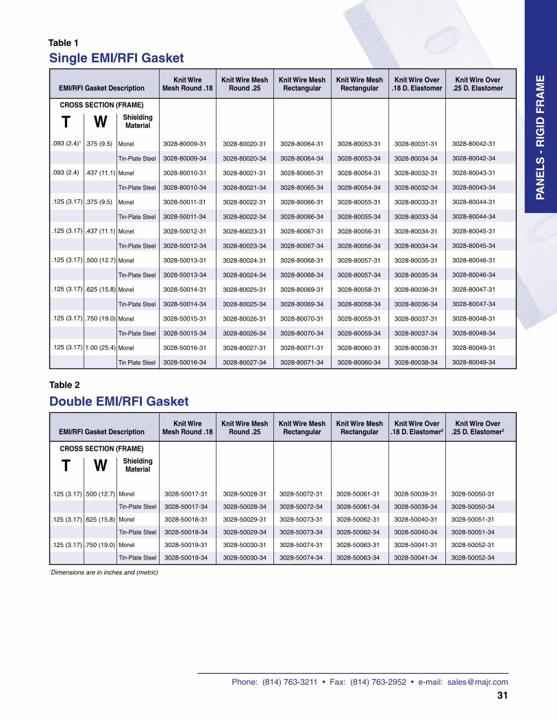
Phone: (814) 763-3211 • Fax: (814) 763-2952 • e-mail: [email protected]
31
Single EMI/RFI Gasket
EMI/RFI Gasket DescriptionKnit Wire
Mesh Round .18Knit Wire Mesh
Round .25Knit Wire Mesh
RectangularKnit Wire Mesh
RectangularKnit Wire Over
.18 D. ElastomerKnit Wire Over
.25 D. Elastomer
CROSS SECTION (FRAME)
T W Shielding Material
.093 (2.4)1
.093 (2.4)
.125 (3.17)
.125 (3.17)
.125 (3.17)
.125 (3.17)
.125 (3.17)
.125 (3.17)
.375 (9.5)
.437 (11.1)
.375 (9.5)
.437 (11.1)
.500 (12.7)
.625 (15.8)
.750 (19.0)
1.00 (25.4)
Monel
Tin-Plate Steel
Monel
Tin-Plate Steel
Monel
Tin-Plate Steel
Monel
Tin-Plate Steel
Monel
Tin-Plate Steel
Monel
Tin-Plate Steel
Monel
Tin-Plate Steel
Monel
Tin Plate Steel
3028-80009-31
3028-80009-34
3028-80010-31
3028-80010-34
3028-50011-31
3028-50011-34
3028-50012-31
3028-50012-34
3028-50013-31
3028-50013-34
3028-50014-31
3028-50014-34
3028-50015-31
3028-50015-34
3028-50016-31
3028-50016-34
3028-80020-31
3028-80020-34
3028-80021-31
3028-80021-34
3028-80022-31
3028-80022-34
3028-80023-31
3028-80023-34
3028-80024-31
3028-80024-34
3028-80025-31
3028-80025-34
3028-80026-31
3028-80026-34
3028-80027-31
3028-80027-34
3028-80064-31
3028-80064-34
3028-80065-31
3028-80065-34
3028-80066-31
3028-80066-34
3028-80067-31
3028-80067-34
3028-80068-31
3028-80068-34
3028-80069-31
3028-80069-34
3028-80070-31
3028-80070-34
3028-80071-31
3028-80071-34
3028-80053-31
3028-80053-34
3028-80054-31
3028-80054-34
3028-80055-31
3028-80055-34
3028-80056-31
3028-80056-34
3028-80057-31
3028-80057-34
3028-80058-31
3028-80058-34
3028-80059-31
3028-80059-34
3028-80060-31
3028-80060-34
3028-80031-31
3028-80034-34
3028-80032-31
3028-80032-34
3028-80033-31
3028-80033-34
3028-80034-31
3028-80034-34
3028-80035-31
3028-80035-34
3028-80036-31
3028-80036-34
3028-80037-31
3028-80037-34
3028-80038-31
3028-80038-34
3028-80042-31
3028-80042-34
3028-80043-31
3028-80043-34
3028-80044-31
3028-80044-34
3028-80045-31
3028-80045-34
3028-80046-31
3028-80046-34
3028-80047-31
3028-80047-34
3028-80048-31
3028-80048-34
3028-80049-31
3028-80049-34
Double EMI/RFI Gasket
.125 (3.17)
.125 (3.17)
.125 (3.17)
.500 (12.7)
.625 (15.8)
.750 (19.0)
Monel
Tin-Plate Steel
Monel
Tin-Plate Steel
Monel
Tin-Plate Steel
3028-50017-31
3028-50017-34
3028-50018-31
3028-50018-34
3028-50019-31
3028-50019-34
3028-50028-31
3028-50028-34
3028-50029-31
3028-50029-34
3028-50030-31
3028-50030-34
3028-50072-31
3028-50072-34
3028-50073-31
3028-50073-34
3028-50074-31
3028-50074-34
3028-50061-31
3028-50061-34
3028-50062-31
3028-50062-34
3028-50063-31
3028-50063-34
3028-50039-31
3028-50039-34
3028-50040-31
3028-50040-34
3028-50041-31
3028-50041-34
*Dimensions are in inches and (metric)
3028-50050-31
3028-50050-34
3028-50051-31
3028-50051-34
3028-50052-31
3028-50052-34
EMI/RFI Gasket DescriptionKnit Wire
Mesh Round .18Knit Wire Mesh
Round .25Knit Wire Mesh
RectangularKnit Wire Mesh
RectangularKnit Wire Over
.18 D. Elastomer2Knit Wire Over
.25 D. Elastomer2
CROSS SECTION (FRAME)
T W Shielding Material
Table 2
Table 1
PAN
EL
S -
RIG
ID F
RA
ME
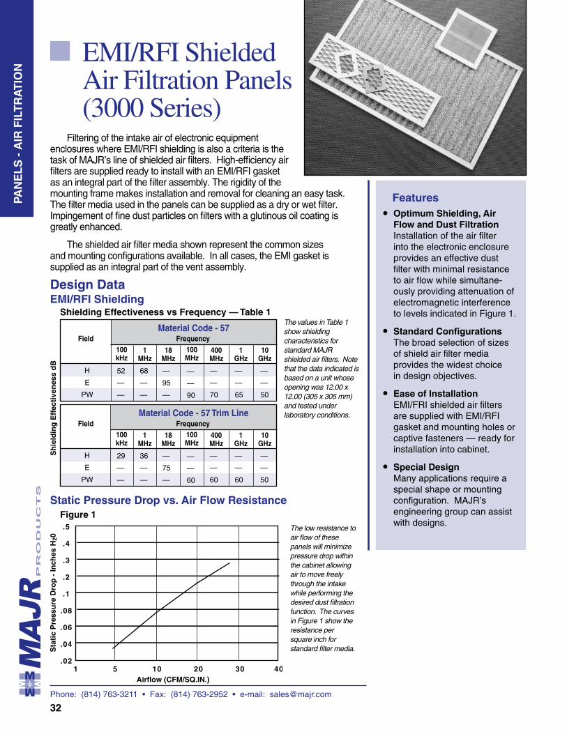
Phone: (814) 763-3211 • Fax: (814) 763-2952 • e-mail: [email protected]
32
EMI/RFI Shielded Air Filtration Panels (3000 Series)
Filtering of the intake air of electronic equipment enclosures where EMI/RFI shielding is also a criteria is the task of MAJR’s line of shielded air filters. High-efficiency air filters are supplied ready to install with an EMI/RFI gasket as an integral part of the filter assembly. The rigidity of the mounting frame makes installation and removal for cleaning an easy task. The filter media used in the panels can be supplied as a dry or wet filter. Impingement of fine dust particles on filters with a glutinous oil coating is greatly enhanced.
The shielded air filter media shown represent the common sizes and mounting configurations available. In all cases, the EMI gasket is supplied as an integral part of the vent assembly.
Features• •
•
•
Optimum Shielding, Air Flow and Dust Filtration Installation of the air filter into the electronic enclosure provides an effective dust filter with minimal resistance to air flow while simultane-ously providing attenuation of electromagnetic interference to levels indicated in Figure 1.
Standard Configurations The broad selection of sizes of shield air filter media provides the widest choice in design objectives.
Ease of Installation EMI/FRI shielded air filters are supplied with EMI/RFI gasket and mounting holes or captive fasteners — ready for installation into cabinet.
Special Design Many applications require a special shape or mounting configuration. MAJR’s engineering group can assist with designs.
Design DataEMI/RFI Shielding
The values in Table 1 show shielding characteristics for standard MAJR shielded air filters. Note that the data indicated is based on a unit whose opening was 12.00 x 12.00 (305 x 305 mm) and tested under laboratory conditions.
Shielding Effectiveness vs Frequency — Table 1
H
E
PW
52
—
—
68
—
—
—
95
—
—
—
90
FieldMaterial Code - 57
100 kHz
1 MHz
18 MHz
100 MHz
Sh
ield
ing
Eff
ecti
ven
ess
dB
400 MHz
1 GHz
Frequency
10 GHz
—
—
70
—
—
65
—
—
50
H
E
PW
29
—
—
36
—
—
—
75
—
—
—
60
FieldMaterial Code - 57 Trim Line
100 kHz
1 MHz
18 MHz
100 MHz
400 MHz
1 GHz
Frequency
10 GHz
—
—
60
—
—
60
—
—
50
Static Pressure Drop vs. Air Flow Resistance
The low resistance to air flow of these panels will minimize pressure drop within the cabinet allowing air to move freely through the intake while performing the desired dust filtration function. The curves in Figure 1 show the resistance per square inch for standard filter media.
Figure 1
P A
N E
L S
PAN
EL
S -
AIR
FIL
TR
AT
ION
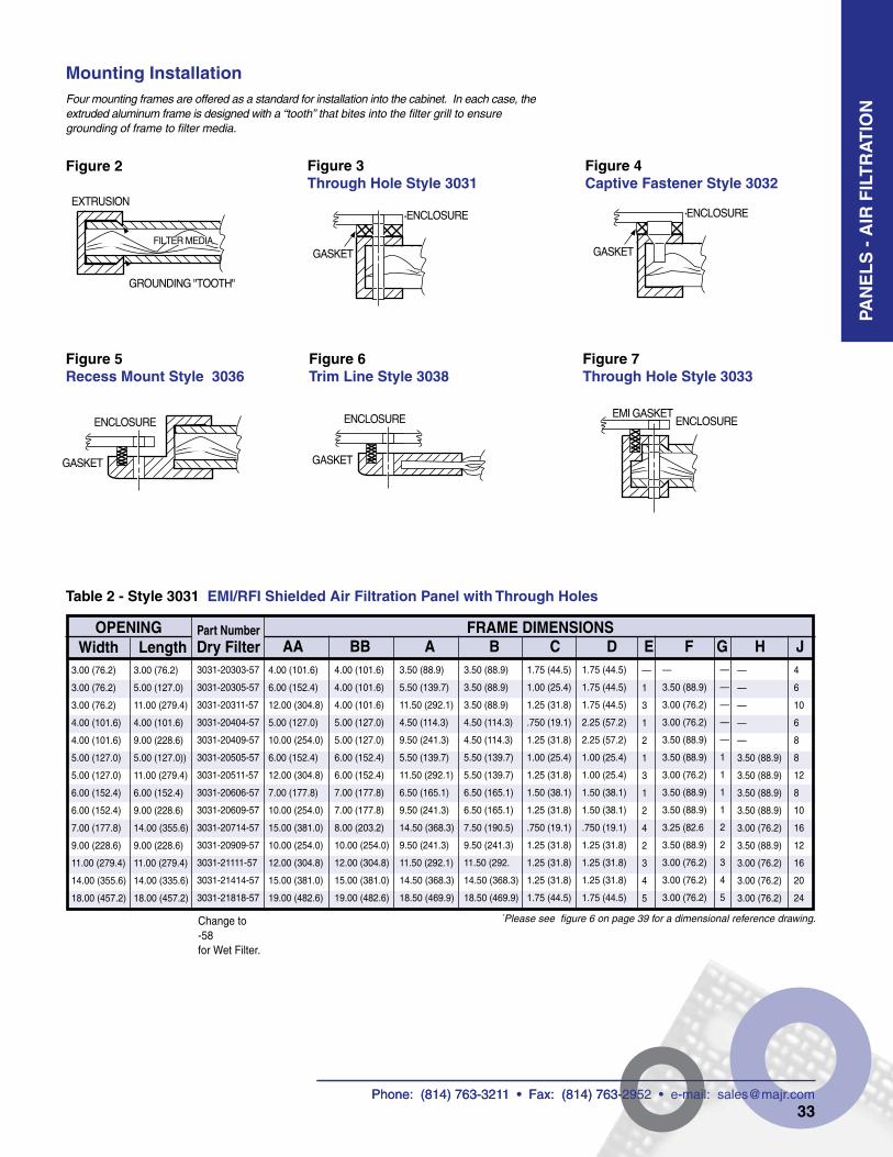
Phone: (814) 763-3211 • Fax: (814) 763-2952 • e-mail: [email protected]
33
AA BB A B C D E F G H J3.00 (76.2)
3.00 (76.2)
3.00 (76.2)
4.00 (101.6)
4.00 (101.6)
5.00 (127.0)
5.00 (127.0)
6.00 (152.4)
6.00 (152.4)
7.00 (177.8)
9.00 (228.6)
11.00 (279.4)
14.00 (355.6)
18.00 (457.2)
Mounting InstallationFour mounting frames are offered as a standard for installation into the cabinet. In each case, the extruded aluminum frame is designed with a “tooth” that bites into the filter grill to ensure grounding of frame to filter media.
Figure 2 Figure 3 Through Hole Style 3031
Figure 4Captive Fastener Style 3032
Figure 5Recess Mount Style 3036
Figure 6Trim Line Style 3038
Figure 7Through Hole Style 3033
Table 2 - Style 3031 EMI/RFI Shielded Air Filtration Panel with Through Holes
OPENING FRAME DIMENSIONSPart Number Dry FilterWidth Length
3.00 (76.2)
5.00 (127.0)
11.00 (279.4)
4.00 (101.6)
9.00 (228.6)
5.00 (127.0))
11.00 (279.4)
6.00 (152.4)
9.00 (228.6)
14.00 (355.6)
9.00 (228.6)
11.00 (279.4)
14.00 (335.6)
18.00 (457.2)
3031-20303-57
3031-20305-57
3031-20311-57
3031-20404-57
3031-20409-57
3031-20505-57
3031-20511-57
3031-20606-57
3031-20609-57
3031-20714-57
3031-20909-57
3031-21111-57
3031-21414-57
3031-21818-57
4.00 (101.6)
6.00 (152.4)
12.00 (304.8)
5.00 (127.0)
10.00 (254.0)
6.00 (152.4)
12.00 (304.8)
7.00 (177.8)
10.00 (254.0)
15.00 (381.0)
10.00 (254.0)
12.00 (304.8)
15.00 (381.0)
19.00 (482.6)
4.00 (101.6)
4.00 (101.6)
4.00 (101.6)
5.00 (127.0)
5.00 (127.0)
6.00 (152.4)
6.00 (152.4)
7.00 (177.8)
7.00 (177.8)
8.00 (203.2)
10.00 (254.0)
12.00 (304.8)
15.00 (381.0)
19.00 (482.6)
3.50 (88.9)
5.50 (139.7)
11.50 (292.1)
4.50 (114.3)
9.50 (241.3)
5.50 (139.7)
11.50 (292.1)
6.50 (165.1)
9.50 (241.3)
14.50 (368.3)
9.50 (241.3)
11.50 (292.1)
14.50 (368.3)
18.50 (469.9)
3.50 (88.9)
3.50 (88.9)
3.50 (88.9)
4.50 (114.3)
4.50 (114.3)
5.50 (139.7)
5.50 (139.7)
6.50 (165.1)
6.50 (165.1)
7.50 (190.5)
9.50 (241.3)
11.50 (292.
14.50 (368.3)
18.50 (469.9)
1.75 (44.5)
1.00 (25.4)
1.25 (31.8)
.750 (19.1)
1.25 (31.8)
1.00 (25.4)
1.25 (31.8)
1.50 (38.1)
1.25 (31.8)
.750 (19.1)
1.25 (31.8)
1.25 (31.8)
1.25 (31.8)
1.75 (44.5)
1.75 (44.5)
1.75 (44.5)
1.75 (44.5)
2.25 (57.2)
2.25 (57.2)
1.00 (25.4)
1.00 (25.4)
1.50 (38.1)
1.50 (38.1)
.750 (19.1)
1.25 (31.8)
1.25 (31.8)
1.25 (31.8)
1.75 (44.5)
—
1
3
1
2
1
3
1
2
4
2
3
4
5
—
3.50 (88.9)
3.00 (76.2)
3.00 (76.2)
3.50 (88.9)
3.50 (88.9)
3.00 (76.2)
3.50 (88.9)
3.50 (88.9)
3.25 (82.6
3.50 (88.9)
3.00 (76.2)
3.00 (76.2)
3.00 (76.2)
—
—
—
—
—
1
1
1
1
2
2
3
4
5
—
—
—
—
—
3.50 (88.9)
3.50 (88.9)
3.50 (88.9)
3.50 (88.9)
3.00 (76.2)
3.50 (88.9)
3.00 (76.2)
3.00 (76.2)
3.00 (76.2)
Change to -58 for Wet Filter.
4
6
10
6
8
8
12
8
10
16
12
16
20
24
Phone: (814) 763-3211 • Fax: (814) 763-2952 • e-mail: [email protected]
PAN
EL
S -
AIR
FIL
TR
AT
ION
*Please see figure 6 on page 39 for a dimensional reference drawing.
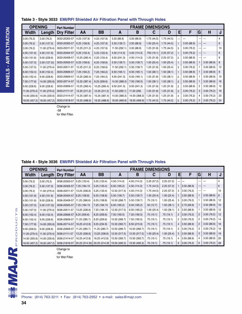
Phone: (814) 763-3211 • Fax: (814) 763-2952 • e-mail: [email protected]
34
Table 3 - Style 3033 EMI/RFI Shielded Air Filtration Panel with Through Holes
AA BB A B C D E F G H J3.00 (76.2)
3.00 (76.2)
3.00 (76.2)
4.00 (101.6)
4.00 (101.6)
5.00 (127.0)
5.00 (127.0)
6.00 (152.4)
6.00 (152.4)
7.00 (177.8)
9.00 (228.6)
11.00 (279.4)
14.00 (355.6)
18.00 (457.2)
OPENING FRAME DIMENSIONSPart Number Dry FilterWidth Length
3.00 (76.2)
5.00 (127.0)
11.00 (279.4)
4.00 (101.6)
9.00 (228.6)
5.00 (127.0))
11.00 (279.4)
6.00 (152.4)
9.00 (228.6)
14.00 (355.6)
9.00 (228.6)
11.00 (279.4)
14.00 (335.6)
18.00 (457.2)
3033-20303-57
3033-20305-57
3033-20311-57
3033-20404-57
3033-20409-57
3033-20505-57
3033-20511-57
3033-20606-57
3033-20609-57
3033-20714-57
3033-20909-57
3033-21111-57
3033-21414-57
3033-21818-57
4.25 (107.9)
6.25 (158.8)
12.25 (311.2)
5.25 (133.4)
10.25 (260.4)
6.25 (158.6)
12.25 (311.2)
7.25 (184.2)
10.25 (260.4)
15.25 (387.4)
10.25 (260.4)
12.25 (311.2)
15.25 (387.4)
19.25 (488.9)
3.50 (88.9)
5.50 (139.7)
11.50 (292.1)
4.50 (114.3)
9.50 (241.3)
5.50 (139.7)
11.50 (292.1)
6.50 (165.1)
9.50 (241.3)
14.50 (368.3)
9.50 (241.3)
11.50 (292.1)
14.50 (368.3)
18.50 (469.9)
3.50 (88.9)
3.50 (88.9)
3.50 (88.9)
4.50 (114.3)
4.50 (114.3)
5.50 (139.7)
5.50 (139.7)
6.50 (165.1)
6.50 (165.1)
7.50 (190.5)
9.50 (241.3)
11.50 (292.
14.50 (368.3)
18.50 (469.9)
1.75 (44.5)
1.00 (25.4)
1.25 (31.8)
.750 (19.1)
1.25 (31.8)
1.00 (25.4)
1.25 (31.8)
1.50 (38.1)
1.25 (31.8)
1.50 (38.1)
1.25 (31.8)
1.25 (31.8)
1.25 (31.8)
1.75 (44.5)
1.75 (44.5)
1.75 (44.5)
1.75 (44.5)
2.25 (57.2)
2.25 (57.2)
1.00 (25.4)
1.00 (25.4)
1.50 (38.1)
1.50 (38.1)
1.50 (38.1)
1.25 (31.8)
1.25 (31.8)
1.25 (31.8)
1.75 (44.5)
—
1
3
1
2
1
3
1
2
3
2
3
4
5
—
3.50 (88.9)
3.00 (76.2)
3.00 (76.2)
3.50 (88.9)
3.50 (88.9)
3.00 (76.2)
3.50 (88.9)
3.50 (88.9)
3.50 (88.9)
3.50 (88.9)
3.00 (76.2)
3.00 (76.2)
3.00 (76.2)
—
—
—
—
—
1
1
1
1
1
2
3
4
5
—
—
—
—
—
3.50 (88.9)
3.50 (88.9)
3.50 (88.9)
3.50 (88.9)
3.50 (88.9)
3.50 (88.9)
3.00 (76.2)
3.00 (76.2)
3.00 (76.2)
4
6
10
6
8
8
12
8
10
16
12
16
20
24
Table 4 - Style 3036 EMI/RFI Shielded Air Filtration Panel with Through Holes
AA BB A B C D E F G H J3.00 (76.2)
3.00 (76.2)
3.00 (76.2)
4.00 (101.6)
4.00 (101.6)
5.00 (127.0)
5.00 (127.0)
6.00 (152.4)
6.00 (152.4)
7.00 (177.8)
9.00 (228.6)
11.00 (279.4)
14.00 (355.6)
18.00 (457.2)
OPENING FRAME DIMENSIONSPart Number Dry FilterWidth Length
3.00 (76.2)
5.00 (127.0)
11.00 (279.4)
4.00 (101.6)
9.00 (228.6)
5.00 (127.0))
11.00 (279.4)
6.00 (152.4)
9.00 (228.6)
14.00 (355.6)
9.00 (228.6)
11.00 (279.4)
14.00 (335.6)
18.00 (457.2)
3036-20303-57
3036-20305-57
3036-20311-57
3036-20404-57
3036-20409-57
3036-20505-57
3036-20511-57
3036-20606-57
3036-20609-57
3036-20714-57
3036-20909-57
3036-21111-57
3036-21414-57
3036-21818-57
4.25 (107.9)
4.25 (107.9)
4.25 (107.9)
5.25 (133.4)
5.25 (133.4)
6.25 (158.6)
6.25 (158.6)
7.25 (184.2)
7.25 (184.2)
8.25 (209.6)
10.25 (260.4)
12.25 (311.2)
15.25 (387.4)
19.25 (488.9)
Change to -58 for Wet Filter.
Change to -58 for Wet Filter.
5.25 (133.4)
7.25 (184.15
13.25 (336.6)
6.25 (158.8)
11.25 (366.6)
7.25 (184.15
13.25 (336.6)
8.25 (209.6)
11.25 (285.7)
16.25 (412.8)
11.25 (285.7)
13.25 (336.6)
16.25 (412.8)
20.25 (514.35)
5.25 (133.4)
5.25 (133.4)
5.25 (133.4)
6.25 (158.8)
6.25 (158.8)
7.25 (184.15
7.25 (184.15
8.25 (209.6)
8.25 (209.6)
9.25 (234.9)
11.25 (285.7)
13.25 (336.6)
16.25 (412.8)
20.25 (514.35
4.50 (114.3)
6.50 (165.2)
12.50 (317.5)
5.50 (139.7)
10.50 (266.7)
6.50 (165.2)
12.50 (317.5)
7.50 (190.5)
10.50 (266.7)
15.50 (393.7)
10.50 (266.7)
12.50 (317.5)
15.50 (393.7)
19.50 (495.3)
4.50 (114.3)
4.50 (114.3)
4.50 (114.3)
5.50 (139.7)
5.50 (139.7)
6.50 (165.2)
6.50 (165.2)
7.50 (190.5)
7.50 (190.5)
8.50 (215.9)
10.50 (266.7)
12.50 (317.5)
15.50 (393.7)
19.50 (495.3)
2.25 (57.2)
1.75 (44.5)
1.75 (44.5)
1.00 (25.4)
.75 (19.1)
.50 (12.7)
1.00 (25.4)
.75 (19.1)
.75 (19.1)
.75 (19.1)
.75 (19.1)
1.00 (25.4)
.75 (19.1)
.75 (19.1)
2.25 (57.2)
2.25 (57.2)
2.25 (57.2)
1.00 (25.4)
1.00 (25.4)
1.50 (38.1)
1.50 (38.1)
.75 (19.1)
.75 (19.1)
.75 (19.1)
.75 (19.1)
1.00 (25.4)
.75 (19.1)
.75 (19.1)
—
1
3
1
3
2
3
2
2
4
3
3
4
6
—
3.50 (88.9)
3.00 (76.2)
3.50 (88.9)
3.00 (76.2)
2.75 (69.9)
3.50 (88.9)
3.00 (76.2)
3.00 (76.2)
3.50 (88.9)
3.00 (76.2)
3.50 (88.9)
3.50 (88.9)
3.00 (76.2)
—
—
—
1
1
1
1
2
2
2
3
3
4
6
—
—
—
3.50 (88.9)
3.50 (88.9)
3.50 (88.9)
3.50 (88.9)
3.00 (76.2)
3.00 (76.2)
3.50 (88.9)
3.00 (76.2)
3.50 (88.9)
3.50 (88.9)
3.00 (76.2)
4
6
10
8
12
10
12
12
14
16
16
16
20
28
PAN
EL
S -
AIR
FIL
TR
AT
ION
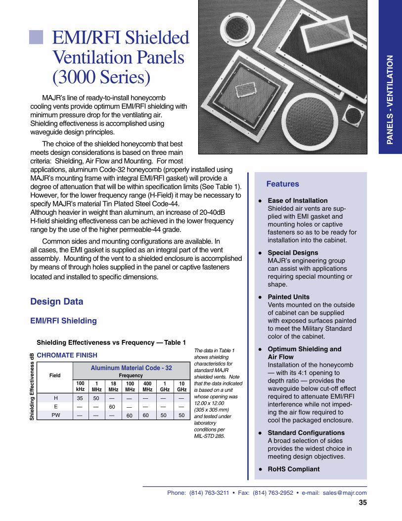
Phone: (814) 763-3211 • Fax: (814) 763-2952 • e-mail: [email protected]
35
EMI/RFI Shielded Ventilation Panels (3000 Series)
Features
•
•
•
•
•
P A
N E
L S
Ease of Installation Shielded air vents are sup-plied with EMI gasket and mounting holes or captive fasteners so as to be ready for installation into the cabinet.
Special Designs MAJR’s engineering group can assist with applications requiring special mounting or shape.
Painted Units Vents mounted on the outside of cabinet can be supplied with exposed surfaces painted to meet the Military Standard color of the cabinet.
Optimum Shielding and Air Flow Installation of the honeycomb — with its 4:1 opening to depth ratio — provides the waveguide below cut-off effect required to attenuate EMI/RFI interference while not imped-ing the air flow required to cool the packaged enclosure.
Standard Configurations A broad selection of sides provides the widest choice in meeting design objectives.
RoHS Compliant
MAJR’s line of ready-to-install honeycomb cooling vents provide optimum EMI/RFI shielding with minimum pressure drop for the ventilating air. Shielding effectiveness is accomplished using waveguide design principles.
The choice of the shielded honeycomb that best meets design considerations is based on three main criteria: Shielding, Air Flow and Mounting. For most applications, aluminum Code-32 honeycomb (properly installed using MAJR’s mounting frame with integral EMI/RFI gasket) will provide a degree of attenuation that will be within specification limits (See Table 1). However, for the lower frequency range (H-Field) it may be necessary to specify MAJR’s material Tin Plated Steel Code-44. Although heavier in weight than aluminum, an increase of 20-40dB H-field shielding effectiveness can be achieved in the lower frequency range by the use of the higher permeable-44 grade.
Common sides and mounting configurations are available. In all cases, the EMI gasket is supplied as an integral part of the vent assembly. Mounting of the vent to a shielded enclosure is accomplished by means of through holes supplied in the panel or captive fasteners located and installed to specific dimensions.
Design Data
EMI/RFI Shielding
Shielding Effectiveness vs Frequency — Table 1
H
E
PW
35
—
—
50
—
—
—
60
—
—
—
60
FieldAluminum Material Code - 32
100 kHz
1 MHz
18 MHz
100 MHz
Sh
ield
ing
Eff
ecti
ven
ess
dB
400 MHz
1 GHz
Frequency
10 GHz
—
—
60
—
—
50
—
—
50
The data in Table 1 shows shielding characteristics for standard MAJR shielded vents. Note that the data indicated is based on a unit whose opening was 12.00 x 12.00 (305 x 305 mm) and tested under laboratory conditions per MIL-STD 285.
CHROMATE FINISH
•
PAN
EL
S -
VE
NT
ILA
TIO
N
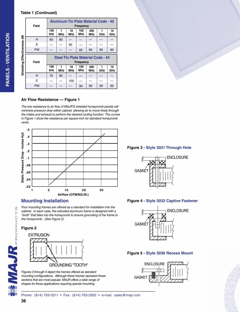
Phone: (814) 763-3211 • Fax: (814) 763-2952 • e-mail: [email protected]
36
H
E
PW
65
—
—
80
—
—
—
90
—
—
—
85
FieldAluminum Tin Plate Material Code - 42
100 kHz
1 MHz
18 MHz
100 MHz
Sh
ield
ing
Eff
ecti
ven
ess
dB
400 MHz
1 GHz
Frequency
10 GHz
—
—
85
—
—
85
—
—
80
H
E
PW
75
—
—
80
—
—
—
100
—
—
—
90
FieldSteel Tin Plate Material Code - 44
100 kHz
1 MHz
18 MHz
100 MHz
400 MHz
1 GHz
Frequency
10 GHz
—
—
90
—
—
90
—
—
85
Air Flow Resistance — Figure 1
The low resistance to air flow of MAJR’S shielded honeycomb panels will minimize pressure drop within cabinet, allowing air to move freely through the intake and exhaust to perform the desired cooling function. The curves in Figure 1 show the resistance per square inch for standard honeycomb vents.
Mounting InstallationFour mounting frames are offered as a standard for installation into the cabinet. In each case, the extruded aluminum frame is designed with a “tooth” that bites into the honeycomb to ensure grounding of the frame to the honeycomb. (See Figure 2).
Figure 2
Figures 3 through 5 depict the frames offered as standard mounting configurations. Although these frames represent those sections that are most popular, MAJR offers a wide range of shapes for those applications requiring special mounting.
Figure 3 - Style 3031 Through Hole
Figure 4 - Style 3032 Captive Fastener
Figure 5 - Style 3036 Recess Mount
Table 1 (Continued)PA
NE
LS
- V
EN
TIL
AT
ION
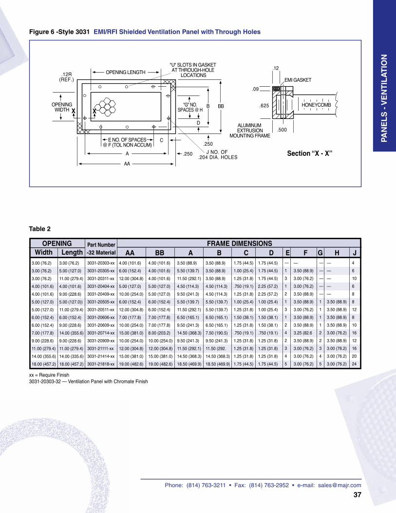
Phone: (814) 763-3211 • Fax: (814) 763-2952 • e-mail: [email protected]
37
3031-20303-xx
3031-20305-xx
3031-20311-xx
3031-20404-xx
3031-20409-xx
3031-20505-xx
3031-20511-xx
3031-20606-xx
3031-20609-xx
3031-20714-xx
3031-20909-xx
3031-21111-xx
3031-21414-xx
3031-21818-xx
3.50 (88.9)
3.50 (88.9)
3.50 (88.9)
4.50 (114.3)
4.50 (114.3)
5.50 (139.7)
5.50 (139.7)
6.50 (165.1)
6.50 (165.1)
7.50 (190.5)
9.50 (241.3)
11.50 (292.
14.50 (368.3)
18.50 (469.9)
Figure 6 -Style 3031 EMI/RFI Shielded Ventilation Panel with Through Holes
AA BB A B C D E F G H J3.00 (76.2)
3.00 (76.2)
3.00 (76.2)
4.00 (101.6)
4.00 (101.6)
5.00 (127.0)
5.00 (127.0)
6.00 (152.4)
6.00 (152.4)
7.00 (177.8)
9.00 (228.6)
11.00 (279.4)
14.00 (355.6)
18.00 (457.2)
OPENING FRAME DIMENSIONSPart Number -32 MaterialWidth Length
3.00 (76.2)
5.00 (127.0)
11.00 (279.4)
4.00 (101.6)
9.00 (228.6)
5.00 (127.0))
11.00 (279.4)
6.00 (152.4)
9.00 (228.6)
14.00 (355.6)
9.00 (228.6)
11.00 (279.4)
14.00 (335.6)
18.00 (457.2)
4.00 (101.6)
4.00 (101.6)
4.00 (101.6)
5.00 (127.0)
5.00 (127.0)
6.00 (152.4)
6.00 (152.4)
7.00 (177.8)
7.00 (177.8)
8.00 (203.2)
10.00 (254.0)
12.00 (304.8)
15.00 (381.0)
19.00 (482.6)
3.50 (88.9)
5.50 (139.7)
11.50 (292.1)
4.50 (114.3)
9.50 (241.3)
5.50 (139.7)
11.50 (292.1)
6.50 (165.1)
9.50 (241.3)
14.50 (368.3)
9.50 (241.3)
11.50 (292.1)
14.50 (368.3)
18.50 (469.9)
1.75 (44.5)
1.00 (25.4)
1.25 (31.8)
.750 (19.1)
1.25 (31.8)
1.00 (25.4)
1.25 (31.8)
1.50 (38.1)
1.25 (31.8)
.750 (19.1)
1.25 (31.8)
1.25 (31.8)
1.25 (31.8)
1.75 (44.5)
1.75 (44.5)
1.75 (44.5)
1.75 (44.5)
2.25 (57.2)
2.25 (57.2)
1.00 (25.4)
1.00 (25.4)
1.50 (38.1)
1.50 (38.1)
.750 (19.1)
1.25 (31.8)
1.25 (31.8)
1.25 (31.8)
1.75 (44.5)
—
1
3
1
2
1
3
1
2
4
2
3
4
5
—
3.50 (88.9)
3.00 (76.2)
3.00 (76.2)
3.50 (88.9)
3.50 (88.9)
3.00 (76.2)
3.50 (88.9)
3.50 (88.9)
3.25 (82.6
3.50 (88.9)
3.00 (76.2)
3.00 (76.2)
3.00 (76.2)
—
—
—
—
—
1
1
1
1
2
2
3
4
5
—
—
—
—
—
3.50 (88.9)
3.50 (88.9)
3.50 (88.9)
3.50 (88.9)
3.00 (76.2)
3.50 (88.9)
3.00 (76.2)
3.00 (76.2)
3.00 (76.2)
4
6
10
6
8
8
12
8
10
16
12
16
20
24
4.00 (101.6)
6.00 (152.4)
12.00 (304.8)
5.00 (127.0)
10.00 (254.0)
6.00 (152.4)
12.00 (304.8)
7.00 (177.8)
10.00 (254.0)
15.00 (381.0)
10.00 (254.0)
12.00 (304.8)
15.00 (381.0)
19.00 (482.6)
xx = Require Finish3031-20303-32 — Ventilation Panel with Chromate Finish
Section “X - X”
Table 2
PAN
EL
S -
VE
NT
ILA
TIO
N
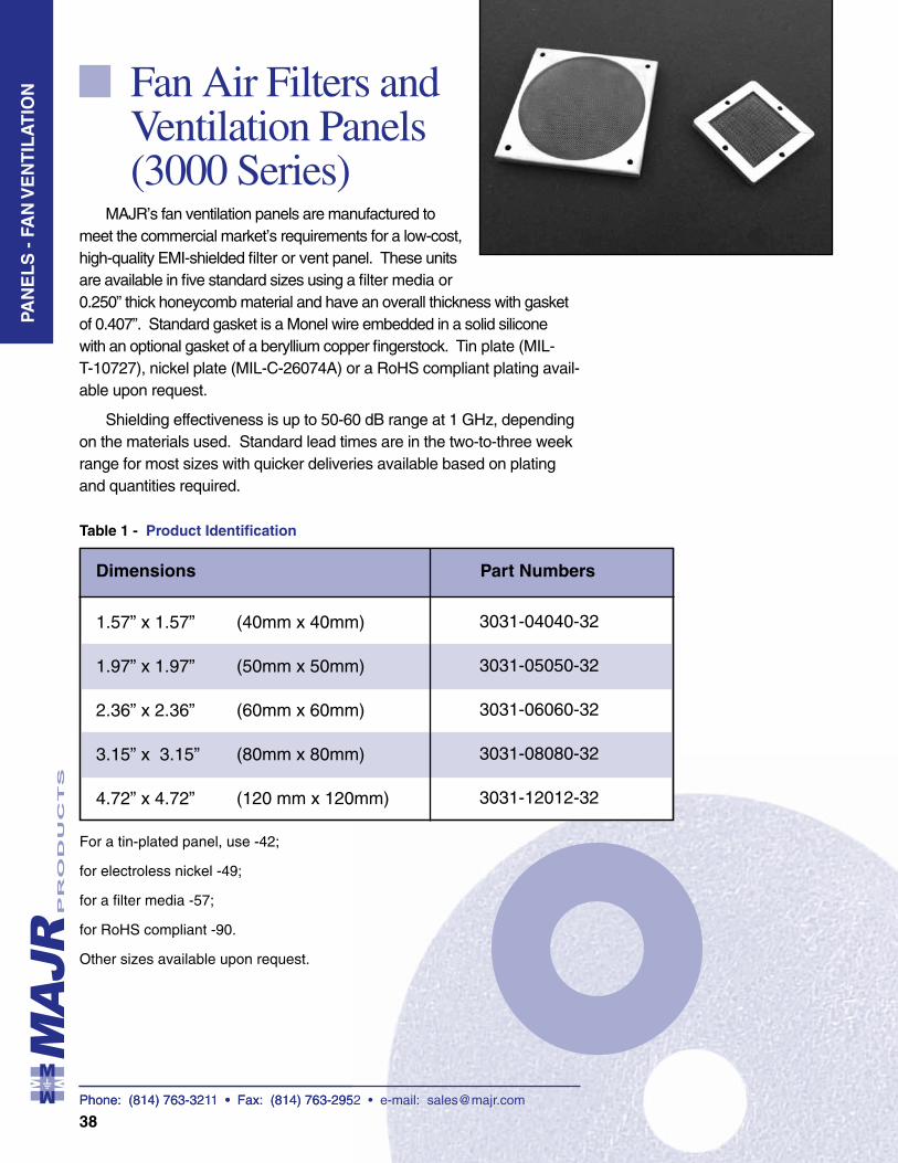
Phone: (814) 763-3211 • Fax: (814) 763-2952 • e-mail: [email protected]
38
Fan Air Filters and Ventilation Panels (3000 Series)
MAJR’s fan ventilation panels are manufactured to meet the commercial market’s requirements for a low-cost, high-quality EMI-shielded filter or vent panel. These units are available in five standard sizes using a filter media or 0.250” thick honeycomb material and have an overall thickness with gasket of 0.407”. Standard gasket is a Monel wire embedded in a solid silicone with an optional gasket of a beryllium copper fingerstock. Tin plate (MIL-T-10727), nickel plate (MIL-C-26074A) or a RoHS compliant plating avail-able upon request.
Shielding effectiveness is up to 50-60 dB range at 1 GHz, depending on the materials used. Standard lead times are in the two-to-three week range for most sizes with quicker deliveries available based on plating and quantities required.
Dimensions Part Numbers
1.57” x 1.57”
1.97” x 1.97”
2.36” x 2.36”
3.15” x 3.15”
4.72” x 4.72”
For a tin-plated panel, use -42;
for electroless nickel -49;
for a filter media -57;
for RoHS compliant -90.
Other sizes available upon request.
(40mm x 40mm)
(50mm x 50mm)
(60mm x 60mm)
(80mm x 80mm)
(120 mm x 120mm)
3031-04040-32
3031-05050-32
3031-06060-32
3031-08080-32
3031-12012-32
Table 1 - Product Identification
Phone: (814) 763-3211 • Fax: (814) 763-2952 • e-mail: [email protected]
P A
N E
L S
PAN
EL
S -
FA
N V
EN
TIL
AT
ION
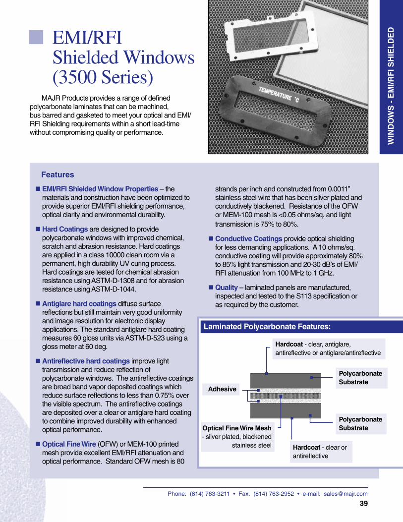
Phone: (814) 763-3211 • Fax: (814) 763-2952 • e-mail: [email protected]
39
EMI/RFI Shielded Windows (3500 Series)
MAJR Products provides a range of defined polycarbonate laminates that can be machined, bus barred and gasketed to meet your optical and EMI/RFI Shielding requirements within a short lead-time without compromising quality or performance.
WIN
DO
WS
- E
MI/R
FI S
HIE
LD
ED
Laminated Polycarbonate Features:
EMI/RFI Shielded Window Properties – the materials and construction have been optimized to provide superior EMI/RFI shielding performance, optical clarity and environmental durability.
Hard Coatings are designed to provide polycarbonate windows with improved chemical, scratch and abrasion resistance. Hard coatings are applied in a class 10000 clean room via a permanent, high durability UV curing process. Hard coatings are tested for chemical abrasion resistance using ASTM-D-1308 and for abrasion resistance using ASTM-D-1044.
Antiglare hard coatings diffuse surface reflections but still maintain very good uniformity and image resolution for electronic display applications. The standard antiglare hard coating measures 60 gloss units via ASTM-D-523 using a gloss meter at 60 deg.
Antireflective hard coatings improve light transmission and reduce reflection of polycarbonate windows. The antireflective coatings are broad band vapor deposited coatings which reduce surface reflections to less than 0.75% over the visible spectrum. The antireflective coatings are deposited over a clear or antiglare hard coating to combine improved durability with enhanced optical performance.
Optical Fine Wire (OFW) or MEM-100 printed mesh provide excellent EMI/RFI attenuation and optical performance. Standard OFW mesh is 80
strands per inch and constructed from 0.0011” stainless steel wire that has been silver plated and conductively blackened. Resistance of the OFW or MEM-100 mesh is <0.05 ohms/sq. and light transmission is 75% to 80%.
Conductive Coatings provide optical shielding for less demanding applications. A 10 ohms/sq. conductive coating will provide approximately 80% to 85% light transmission and 20-30 dB’s of EMI/ RFI attenuation from 100 MHz to 1 GHz.
Quality – laminated panels are manufactured, inspected and tested to the S113 specification or as required by the customer.
Optical Fine Wire Mesh - silver plated, blackened
stainless steel
Hardcoat - clear, antiglare, antireflective or antiglare/antireflective
Polycarbonate Substrate
Adhesive
Hardcoat - clear or antireflective
Polycarbonate Substrate
Features
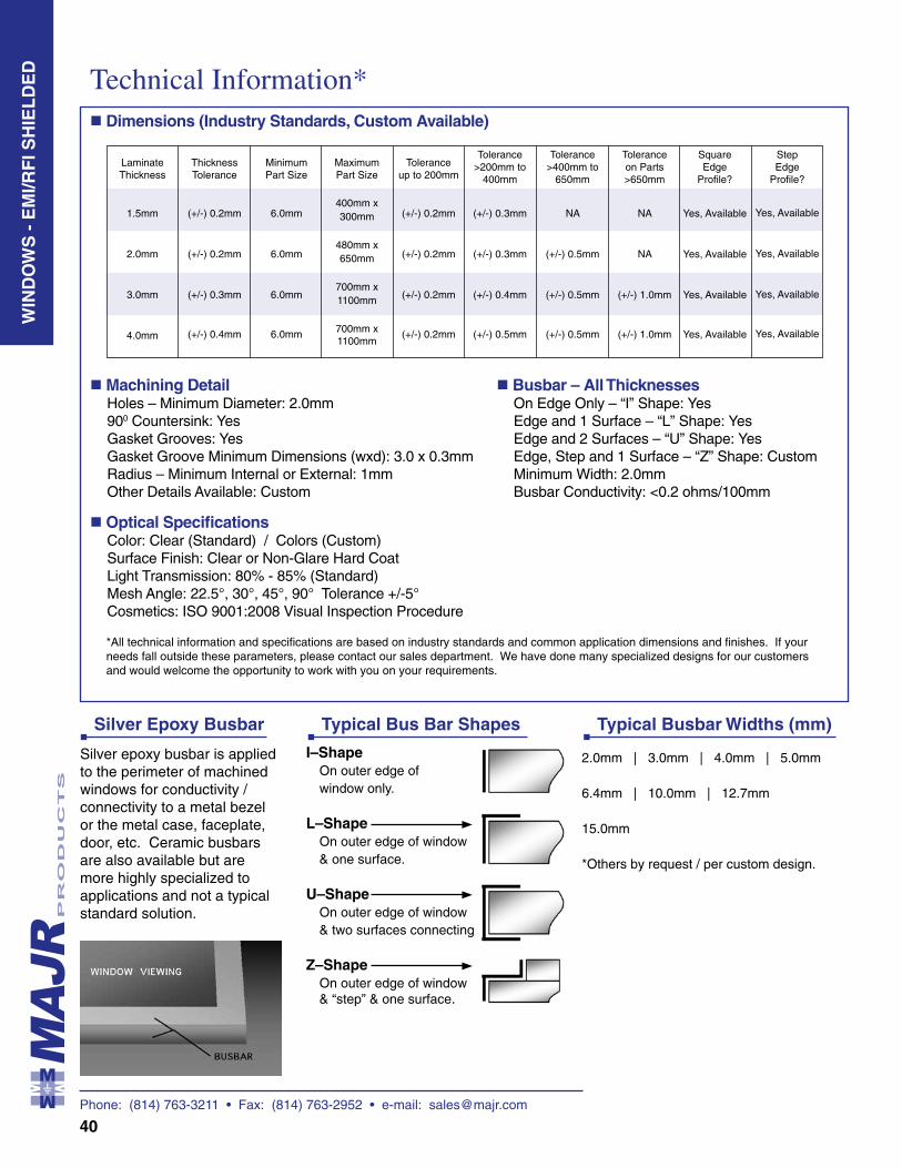
Phone: (814) 763-3211 • Fax: (814) 763-2952 • e-mail: [email protected]
40
Machining DetailHoles – Minimum Diameter: 2.0mm900 Countersink: YesGasket Grooves: YesGasket Groove Minimum Dimensions (wxd): 3.0 x 0.3mmRadius – Minimum Internal or External: 1mmOther Details Available: Custom
Optical SpecificationsColor: Clear (Standard) / Colors (Custom)Surface Finish: Clear or Non-Glare Hard Coat Light Transmission: 80% - 85% (Standard)Mesh Angle: 22.5°, 30°, 45°, 90° Tolerance +/-5°Cosmetics: ISO 9001:2008 Visual Inspection Procedure
Technical Information* Dimensions (Industry Standards, Custom Available)
WIN
DO
WS
- E
MI/R
FI S
HIE
LD
ED
Silver Epoxy Busbar
Silver epoxy busbar is applied to the perimeter of machined windows for conductivity / connectivity to a metal bezel or the metal case, faceplate, door, etc. Ceramic busbars are also available but are more highly specialized to applications and not a typical standard solution.
I–Shape On outer edge of
window only.
L–Shape On outer edge of window
& one surface.
U–Shape On outer edge of window
& two surfaces connecting.
Z–Shape On outer edge of window
& “step” & one surface.
2.0mm | 3.0mm | 4.0mm | 5.0mm
6.4mm | 10.0mm | 12.7mm
15.0mm
*Others by request / per custom design.
Typical Bus Bar Shapes Typical Busbar Widths (mm)
Laminate Thickness
1.5mm
2.0mm
3.0mm
4.0mm
Thickness Tolerance
(+/-) 0.2mm
(+/-) 0.2mm
(+/-) 0.3mm
(+/-) 0.4mm
Minimum Part Size
6.0mm
6.0mm
6.0mm
6.0mm
Maximum Part Size
400mm x 300mm
480mm x 650mm
700mm x 1100mm
700mm x 1100mm
Tolerance up to 200mm
(+/-) 0.2mm
(+/-) 0.2mm
(+/-) 0.2mm
(+/-) 0.2mm
Tolerance >200mm to
400mm
(+/-) 0.3mm
(+/-) 0.3mm
(+/-) 0.4mm
(+/-) 0.5mm
Tolerance >400mm to
650mm
NA
(+/-) 0.5mm
(+/-) 0.5mm
(+/-) 0.5mm
Tolerance on Parts >650mm
NA
NA
(+/-) 1.0mm
(+/-) 1.0mm
Square Edge
Profile?
Yes, Available
Yes, Available
Yes, Available
Yes, Available
Step Edge
Profile?
Yes, Available
Yes, Available
Yes, Available
Yes, Available
Busbar – All ThicknessesOn Edge Only – “I” Shape: YesEdge and 1 Surface – “L” Shape: Yes Edge and 2 Surfaces – “U” Shape: YesEdge, Step and 1 Surface – “Z” Shape: CustomMinimum Width: 2.0mmBusbar Conductivity: <0.2 ohms/100mm
*All technical information and specifications are based on industry standards and common application dimensions and finishes. If your needs fall outside these parameters, please contact our sales department. We have done many specialized designs for our customers and would welcome the opportunity to work with you on your requirements.
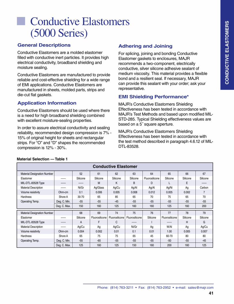
Phone: (814) 763-3211 • Fax: (814) 763-2952 • e-mail: [email protected]
41
General Descriptions
Conductive Elastomers are a molded elastomer filled with conductive inert particles. It provides high electrical conductivity, broadband shielding and moisture sealing.
Conductive Elastomers are manufactured to provide reliable and cost-effective shielding for a wide range of EMI applications. Conductive Elastomers are manufactured in sheets, molded parts, strips and die-cut flat gaskets.
Application Information
Conductive Elastomers should be used where there is a need for high broadband shielding combined with excellent moisture-sealing properties.
In order to assure electrical conductivity and sealing reliability, recommended design compression is 7% - 15% of original height for sheets and rectangular strips. For “O” and “D” shapes the recommended compression is 12% - 30%.
Conductive Elastomers (5000 Series)
Adhering and Joining
For splicing, joining and bonding Conductive Elastomer gaskets to enclosures, MAJR recommends a two-component, electrically conductive, silver silicone adhesive sealant of medium viscosity. This material provides a flexible bond and a resilient seal. If necessary, MAJR can provide this sealant with your order; ask your representative.
EMI Shielding Performance*
MAJR’s Conductive Elastomers Shielding Effectiveness has been tested in accordance with MAJR’s Test Methods and based upon modified MIL-STD-285. Typical Shielding effectiveness values are based on a 5˝ square aperture.
MAJR’s Conductive Elastomers Shielding Effectiveness has been tested in accordance with the test method described in paragraph 4.6.12 of MIL-DTL-83528.
CO
ND
UC
TIV
E E
LA
STO
ME
RS
Material Designation Number 52 61 62 63 64 65 66 67
Elastomer ------ Silicone Silicone Silicone Silicone Fluorosilicone Silicone Silicone Silicone
MIL-DTL-83528 Type ------ ------ M K B D L E ------
Material Description ------ Ni/Gr Ag/Glass Ag/Cu Ag/Al Ag/Al Ag/Ni Ag Carbon
Volume resistivity Ohm-cm 0.1 0.006 0.005 0.008 0.012 0.005 0.002 7
Hardness Shore A 30-70 65 85 65 70 75 65 70
Operating Temp. Deg. C. Min. -55 -55 -45 -55 -55 -55 -55 -55
Deg. C. Max. 150 160 125 160 160 125 160 200
Material Designation Number 68 69 74 75 76 77 78 79
Elastomer ------ Silicone Fluorosilicone Fluorosilicone Fluorosilicone Silicone Fluorosilicone Silicone Silicone
MIL-DTL-83528 Type ------ A F C ------ I ------ H G
Material Description ------ Ag/Cu Ag Ag/Cu Ni/Gr Ag W/Al Ag Ag/Cu
Volume resistivity Ohm-cm 0.004 0.002 0.01 0.1 0.01 1.00 0.005 0.007
Hardness Shore A 65 75 75 65 45 60-70 80 80
Operating Temp. Deg. C. Min. -55 -65 -55 -55 -55 -50 -55 -45
Deg. C. Max. 125 160 125 150 160 200 160 125
Material Selection — Table 1
Conductive Elastomer
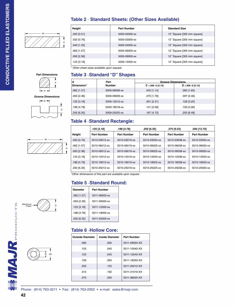
Phone: (814) 763-3211 • Fax: (814) 763-2952 • e-mail: [email protected]
42
Table 6 -Hollow Core: Outside Diameter Inside Diameter Part Number
.090 .050 5011-09050-XX
.103 .040 5011-10040-XX
.125 .045 5011-12045-XX
.156 .050 5011-16050-XX
.250 .125 5011-25012-XX
.312 .192 5011-31019-XX
.375 .250 5011-38025-XX
Table 5 -Standard Round: Diameter Part Number
.062 [1.57] 5011-06000-xx
.093 [2.36] 5011-09000-xx
.125 [3.18] 5011-12000-xx
.188 [4.78] 5011-18000-xx
.250 [6.35] 5011-25000-xx
CO
ND
UC
TIV
E F
ILL
ED
EL
AS
TOM
ER
S
Table 2 - Standard Sheets: (Other Sizes Available)
Height Part Number Standard Size
.020 [0.51] 5000-02000-xx 12˝ Square [305 mm square]
.032 [0.76] 5000-03000-xx 12˝ Square [305 mm square]
.040 [1.02] 5000-04000-xx 12˝ Square [305 mm square]
.062 [1.57] 5000-06000-xx 12˝ Square [305 mm square]
.093 [2.36] 5000-09000-xx 12˝ Square [305 mm square]
.125 [3.18] 5000-12000-xx 12˝ Square [305 mm square]
* Other sheet sizes available upon request.
Part Dimensions
Groove Dimensions
*Other dimensions of this part are available upon request.
Table 4 -Standard Rectangle:
.125 [3.18] .188 [4.78] .250 [6.35] .375 [9.53] .500 [12.70]
Height Part Number Part Number Part Number Part Number Part Number
.032 [0.76] 5010-03012-xx 5010-03019-xx 5010-03025-xx 5010-03038-xx 5010-03050-xx
.062 [1.57] 5010-06012-xx 5010-06019-xx 5010-06025-xx 5010-06038-xx 5010-06050-xx
.093 [2.36] 5010-09012-xx 5010-09019-xx 5010-09025-xx 5010-09038-xx 5010-09050-xx
.125 [3.18] 5010-12012-xx 5010-12019-xx 5010-12025-xx 5010-12038-xx 5010-12050-xx
.188 [4.78] 5010-18012-xx 5010-18019-xx 5010-18025-xx 5010-18038-xx 5010-18050-xx
.250 [6.35] 5010-25012-xx 5010-25019-xx 5010-25025-xx 5010-25038-xx 5010-25050-xx
Table 3 -Standard “D” Shapes A Part Groove Dimensions Dimension* Number C +.006 -0 [0.15] D +.006 -0 [0.15]
.062 [1.57] 5009-06006-xx .045 [1.14] .065 [1.65]
.093 [2.36] 5009-09009-xx .070 [1.78] .097 [2.46]
.125 [3.18] 5009-12012-xx .091 [2.31] .128 [3.25]
.188 [4.78] 5009-18018-xx .141 [3.58] .193 [4.90]
.250 [6.35] 5009-25025-xx .187 [4.75] .255 [6.48]
ID OD
B
B
D
A
A
C
C Radius
D
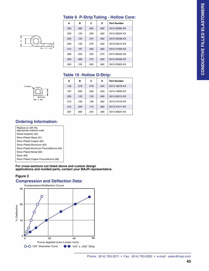
Phone: (814) 763-3211 • Fax: (814) 763-2952 • e-mail: [email protected]
43
Ordering Information: Replace xx with the appropriate material code:
Nickel Graphite (52)
Silver-Plated Glass (61)
Silver-Plated Copper (62)
Silver-Plated Aluminum (63)
Silver-Plated Aluminum FluoroSilicone (64)
Silver-Plated Nickel (65)
Silver (66)
Silver Plated Copper Fluorosilicone (68)
For cross-sections not listed above and custom design applications and molded parts, contact your MAJR representative.
Compression and Deflection Data:Figure 3
Table 9 -P-Strip Tubing - Hollow Core: A B C D Part Number
.200 .080 .650 .062 5012-20065-XX
.250 .125 .250 .062 5012-25025-XX
.250 .125 .375 .062 5012-25038-XX
.250 .150 .375 .062 5012-25015-XX
.312 .187 .563 .062 5012-31056-XX
.360 .255 .420 .070 5012-36042-XX
.200 .080 .275 .062 5012-20028-XX
.250 .125 .625 .062 5012-25063-XX
Table 10 -Hollow D-Strip: A B C D Part Number
.156 .078 .078 .045 5013-16078-XX
.187 .093 .093 .050 5013-19093-XX
.250 .125 .125 .065 5013-25013-XX
.312 .156 .156 .062 5013-31016-XX
.312 .200 .112 .062 5013-31011-XX
.487 .080 .244 .080 5013-48024-XX
CO
ND
UC
TIV
E F
ILL
ED
EL
AS
TOM
ER
S
ID OD
B
B
D
A
A
C
C Radius
D
ID OD
B
B
D
A
A
C
C Radius
D
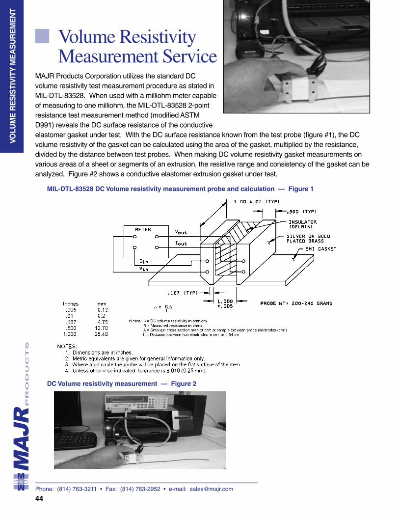
Phone: (814) 763-3211 • Fax: (814) 763-2952 • e-mail: [email protected]
44
Volume Resistivity Measurement Service
MAJR Products Corporation utilizes the standard DC volume resistivity test measurement procedure as stated in MIL-DTL-83528. When used with a milliohm meter capable of measuring to one milliohm, the MIL-DTL-83528 2-point resistance test measurement method (modified ASTM D991) reveals the DC surface resistance of the conductive elastomer gasket under test. With the DC surface resistance known from the test probe (figure #1), the DC volume resistivity of the gasket can be calculated using the area of the gasket, multiplied by the resistance, divided by the distance between test probes. When making DC volume resistivity gasket measurements on various areas of a sheet or segments of an extrusion, the resistive range and consistency of the gasket can be analyzed. Figure #2 shows a conductive elastomer extrusion gasket under test.
P A
N E
L S
VOLU
ME
RE
SIS
TIV
ITY
ME
AS
UR
EM
EN
T
MIL-DTL-83528 DC Volume resistivity measurement probe and calculation — Figure 1
DC Volume resistivity measurement — Figure 2
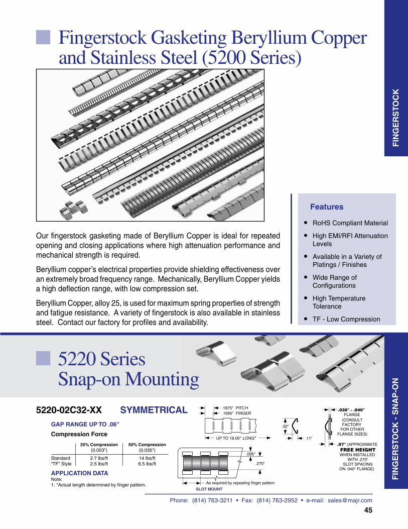
45
FIN
GE
RS
TOC
K -
SN
AP
-ON
FIN
GE
RS
TOC
K
Fingerstock Gasketing Beryllium Copper and Stainless Steel (5200 Series)
Our fingerstock gasketing made of Beryllium Copper is ideal for repeated opening and closing applications where high attenuation performance and mechanical strength is required.
Beryllium copper’s electrical properties provide shielding effectiveness over an extremely broad frequency range. Mechanically, Beryllium Copper yields a high deflection range, with low compression set.
Beryllium Copper, alloy 25, is used for maximum spring properties of strength and fatigue resistance. A variety of fingerstock is also available in stainless steel. Contact our factory for profiles and availability.
Features
• RoHS Compliant Material
• High EMI/RFI Attenuation Levels
• Available in a Variety of Platings / Finishes
• Wide Range of Configurations
• High Temperature Tolerance
• TF - Low Compression
GAP RANGE UP TO .06"
APPLICATION DATANote:1. *Actual length determined by finger pattern.
UP TO 18.00" LONG*
.1875"
.1695"PITCHFINGER
.11"
.32"
As required by repeating finger pattern
.270"
.095"
.07" (APPROXIMATE FREE HEIGHTWHEN INSTALLED
WITH .270"SLOT SPACING
ON .040" FLANGE)
.030" - .040" FLANGE
SLOT MOUNT
(CONSULTFACTORY
FOR OTHERFLANGE SIZES)Compression Force
25% Compression 50% Compression (0.053") (0.035")
Standard 2.7 lbs/ft 14 lbs/ft“TF” Style 2.5 lbs/ft 6.5 lbs/ft
5220-02C32-XX SYMMETRICAL
5220 Series Snap-on Mounting
Phone: (814) 763-3211 • Fax: (814) 763-2952 • e-mail: [email protected]
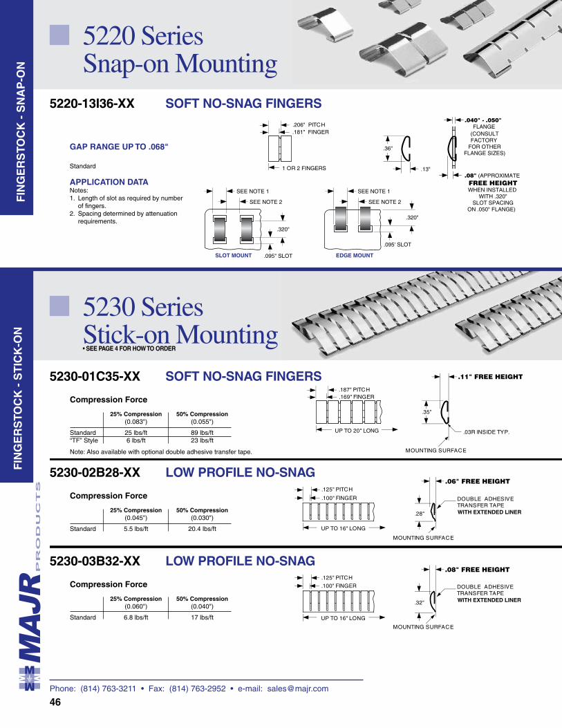
Phone: (814) 763-3211 • Fax: (814) 763-2952 • e-mail: [email protected]
46
.169" FINGER
.187" PITCH
UP TO 20" LONG
.35"
.11" FREE HEIGHT
.03R INSIDE TYP.
MOUNTING SURFACE
.06" FREE HEIGHT
.28"
MOUNTING SURFACE
UP TO 16" LONG
.100" FINGER
.125" PITCH
DOUBLE ADHESIVETRANSFER TAPEWITH EXTENDED LINER
.08" FREE HEIGHT
.32"
MOUNTING SURFACE
UP TO 16" LONG
.100" FINGER
.125" PITCH
DOUBLE ADHESIVETRANSFER TAPEWITH EXTENDED LINER
Compression Force
25% Compression 50% Compression (0.083") (0.055")
Standard 25 lbs/ft 89 lbs/ft“TF” Style 6 lbs/ft 23 lbs/ft
Note: Also available with optional double adhesive transfer tape.
Compression Force
25% Compression 50% Compression (0.045") (0.030")
Standard 5.5 lbs/ft 20.4 lbs/ft
Compression Force
25% Compression 50% Compression (0.060") (0.040")
Standard 6.8 lbs/ft 17 lbs/ft
5230-01C35-XX SOFT NO-SNAG FINGERS
5230-02B28-XX LOW PROFILE NO-SNAG
5230-03B32-XX LOW PROFILE NO-SNAG
5230 Series Stick-on Mounting• SEE PAGE 4 FOR HOW TO ORDER
GAP RANGE UP TO .068"
Standard
APPLICATION DATANotes:1. Length of slot as required by number of fingers.2. Spacing determined by attenuation requirements.
.320"
.095" SLOT
SEE NOTE 1
SEE NOTE 2
SEE NOTE 1
SEE NOTE 2
.320"
.095' SLOT
SLOT MOUNT EDGE MOUNT
.181" FINGER
.206" PITCH
1 OR 2 FINGERS
.36"
.13".08" (APPROXIMATE FREE HEIGHTWHEN INSTALLED
WITH .320"SLOT SPACING
ON .050" FLANGE)
.040" - .050" FLANGE
(CONSULTFACTORY
FOR OTHERFLANGE SIZES)
5220-13I36-XX SOFT NO-SNAG FINGERS
5220 Series Snap-on Mounting
FIN
GE
RS
TOC
K -
SN
AP
-ON
FIN
GE
RS
TOC
K -
ST
ICK
-ON
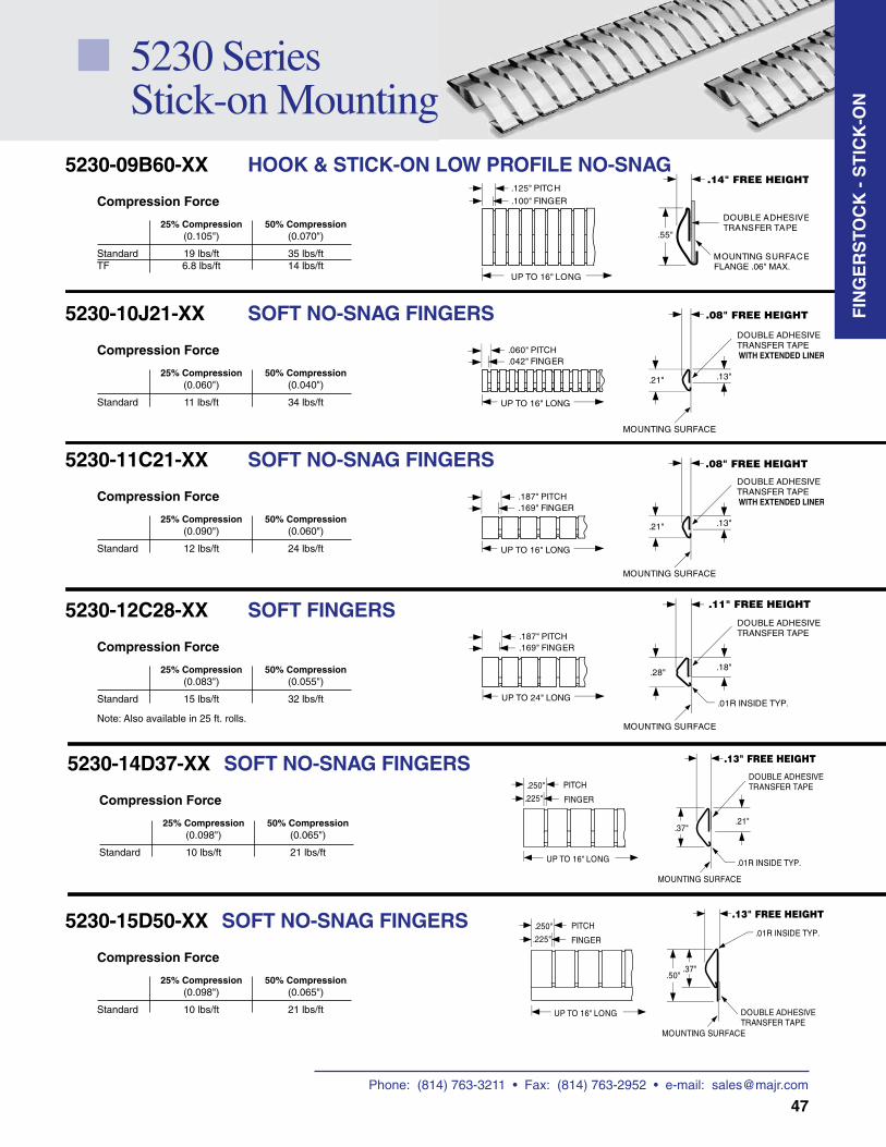
Phone: (814) 763-3211 • Fax: (814) 763-2952 • e-mail: [email protected]
47
5230 Series Stick-on Mounting
FIN
GE
RS
TOC
K -
ST
ICK
-ON
.55"
MOUNTING SURFACE
UP TO 16" LONG
.100" FINGER
.125" PITCH
DOUBLE ADHESIVETRANSFER TAPE
FLANGE .06" MAX.
.14" FREE HEIGHT
Compression Force
25% Compression 50% Compression (0.105") (0.070")
Standard 19 lbs/ft 35 lbs/ftTF 6.8 lbs/ft 14 lbs/ft
5230-09B60-XX HOOK & STICK-ON LOW PROFILE NO-SNAG
.169" FINGER
.187" PITCH
UP TO 24" LONG
.28"
.01R INSIDE TYP.
.18"
DOUBLE ADHESIVETRANSFER TAPE
MOUNTING SURFACE
.11" FREE HEIGHT
.169" FINGER
.187" PITCH
UP TO 16" LONG
.21" .13"
DOUBLE ADHESIVETRANSFER TAPE
MOUNTING SURFACE
WITH EXTENDED LINER
.08" FREE HEIGHT
.042" FINGER
.060" PITCH
UP TO 16" LONG
.21" .13"
DOUBLE ADHESIVETRANSFER TAPE
MOUNTING SURFACE
WITH EXTENDED LINER
.08" FREE HEIGHT
Compression Force
25% Compression 50% Compression (0.060") (0.040")
Standard 11 lbs/ft 34 lbs/ft
Compression Force
25% Compression 50% Compression (0.090") (0.060")
Standard 12 lbs/ft 24 lbs/ft
Compression Force
25% Compression 50% Compression (0.083") (0.055")
Standard 15 lbs/ft 32 lbs/ft
Note: Also available in 25 ft. rolls.
5230-10J21-XX SOFT NO-SNAG FINGERS
5230-11C21-XX SOFT NO-SNAG FINGERS
5230-12C28-XX SOFT FINGERS
Compression Force
25% Compression 50% Compression (0.098") (0.065")
Standard 10 lbs/ft 21 lbs/ft
5230-14D37-XX SOFT NO-SNAG FINGERS
.225"
.250"
UP TO 16" LONG
.21".37"
DOUBLE ADHESIVETRANSFER TAPE
.01R INSIDE TYP.
PITCH
FINGER
MOUNTING SURFACE
.13" FREE HEIGHT
Compression Force
25% Compression 50% Compression (0.098") (0.065")
Standard 10 lbs/ft 21 lbs/ft
5230-15D50-XX SOFT NO-SNAG FINGERS .225"
.250"
UP TO 16" LONG
.37"
DOUBLE ADHESIVETRANSFER TAPE
.01R INSIDE TYP.
.50"
PITCH
FINGER
MOUNTING SURFACE
.13" FREE HEIGHT
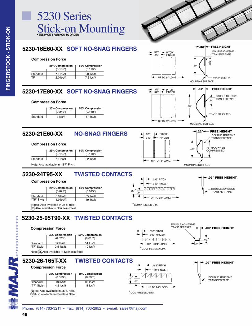
Phone: (814) 763-3211 • Fax: (814) 763-2952 • e-mail: [email protected]
48
5230 Series Stick-on Mounting• SEE PAGE 4 FOR HOW TO ORDER
FIN
GE
RS
TOC
K -
ST
ICK
-ON
Compression Force
25% Compression 50% Compression (0.165") (0.110")
Standard 10 lbs/ft 20 lbs/ftTF 2.0 lbs/ft 7.2 lbs/ft
Compression Force
25% Compression 50% Compression (0.240") (0.160")
Standard 7 lbs/ft 17 lbs/ft
5230-16E60-XX SOFT NO-SNAG FINGERS
5230-17E80-XX SOFT NO-SNAG FINGERS .343".375"
UP TO 24" LONG
.44"
.80"
DOUBLE ADHESIVETRANSFER TAPE
.04R INSIDE TYP.
PITCHFINGER
MOUNTING SURFACE
FREE HEIGHT.32"
.343".375"
UP TO 24" LONG
DOUBLE ADHESIVETRANSFER TAPE
.04R INSIDE TYP.
.28"
.60"
PITCH*FINGER
MOUNTING SURFACE
FREE HEIGHT.22"
.080" FINGER
.095" PITCH
.14".23"*
UP TO 24" LONG
DOUBLE ADHESIVETRANSFER TAPE
* COMPRESSED DIM.
.03" FREE HEIGHT
.343"
.375"
UP TO 18" LONG
DOUBLE ADHESIVETRANSFER TAPE
.78" MAX. WHENCOMPRESSED
.60"
PITCH
FINGER
MOUNTING SURFACE
*FREE HEIGHT.22"
Compression Force
25% Compression 50% Compression (0.165") (0.110")
Standard 13 lbs/ft 32 lbs/ft
Note: Also available in .187" Pitch.
Compression Force
25% Compression 50% Compression (0.023") (0.015")
Standard 5.8 lbs/ft 35 lbs/ft“TF” Style 4.9 lbs/ft 19 lbs/ft
Notes: Also available in 25 ft. rolls.SS Also available in Stainless Steel
5230-21E60-XX NO-SNAG FINGERS
5230-24T95-XX TWISTED CONTACTS
.150" FINGER
.165" PITCH
.18".34"
UP TO 24" LONG
DOUBLE ADHESIVETRANSFER TAPE
COMPRESSED DIM.*
*
.07" FREE HEIGHT
Compression Force
25% Compression 50% Compression (0.053") (0.035")
Standard 18 lbs/ft 36 lbs/ft“TF” Style 4.2 lbs/ft 11 lbs/ft
Notes: Also available in 25 ft. rolls.SS Also available in Stainless Steel
Compression Force
25% Compression 50% Compression (0.023") (0.015")
Standard 12 lbs/ft 51 lbs/ft“TF” Style 2.5 lbs/ft 10 lbs/ft
Note: SS Also available in Stainless Steel
5230-25-95T90-XX TWISTED CONTACTS
5230-26-165T-XX TWISTED CONTACTS
.080" FINGER.095" PITCH
UP TO 24" LONG
.09"*.14"
DOUBLE ADHESIVETRANSFER TAPE
* COMPRESSED DIM.
.03" FREE HEIGHT
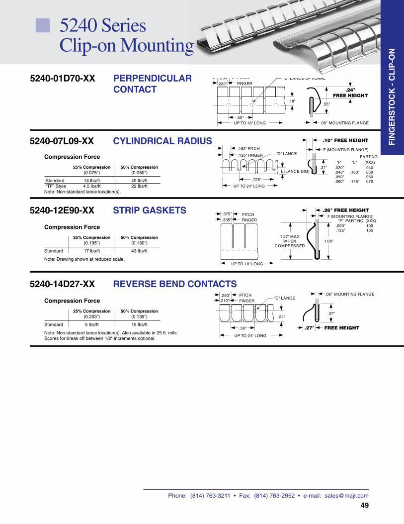
Phone: (814) 763-3211 • Fax: (814) 763-2952 • e-mail: [email protected]
49
.210".250" PITCH
FINGER
UP TO 24" LONG
.37"
.06" MOUNTING FLANGE"D" LANCE
.24"
.50" FREE HEIGHT.27"
Compression Force
25% Compression 50% Compression (0.203") (0.135")
Standard 5 lbs/ft 15 lbs/ft
Note: Non-standard lance location(s). Also available in 25 ft. rolls.Scores for break off between 1/2" increments optional.
5240-14D27-XX REVERSE BEND CONTACTS
.335"
.375"
UP TO 18" LONG
1.27" MAXWHEN
COMPRESSED
F (MOUNTING FLANGE)"F" PART NO. (XXX)FINGER
PITCH
1.09"
.090" 100
.125" 135
.26" FREE HEIGHT
Compression Force
25% Compression 50% Compression (0.195") (0.130")
Standard 17 lbs/ft 43 lbs/ft
Note: Drawing shown at reduced scale.
5240-12E90-XX STRIP GASKETS
.135" FINGER
.182" PITCH
UP TO 24" LONG
.31"
F (MOUNTING FLANGE)
"F"
L (LANCE DIM)
"D" LANCE
040050060070
.030"
.040"
.050"
.060"
.163"
.148"
PART NO.(XXX)"L"
.728"
.10" FREE HEIGHT
Compression Force
25% Compression 50% Compression (0.075") (0.050")
Standard 14 lbs/ft 49 lbs/ft “TF” Style 4.5 lbs/ft 22 lbs/ft Note: Non-standard lance location(s).
5240-07L09-XX CYLINDRICAL RADIUS
.220"
.250" PITCH
FINGER
UP TO 16" LONG .06"
.55"
MOUNTING FLANGE
"D" LANCE OPTIONAL
.50"
.18"
.24"FREE HEIGHT
5240 Series Clip-on Mounting
FIN
GE
RS
TOC
K -
CL
IP-O
N
5240-01D70-XX PERPENDICULAR CONTACT
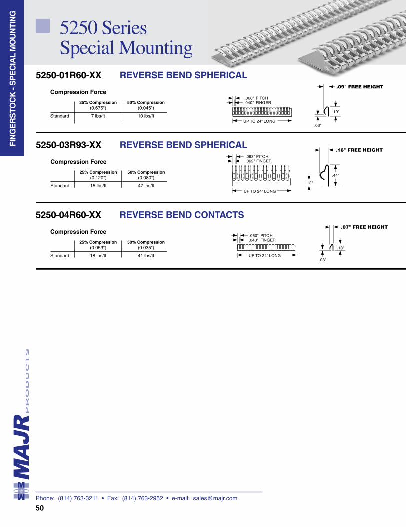
Phone: (814) 763-3211 • Fax: (814) 763-2952 • e-mail: [email protected]
50
.062"
.093"FINGERPITCH
UP TO 24" LONG
.44"
.12"
.16" FREE HEIGHT
Compression Force
25% Compression 50% Compression (0.120") (0.080")
Standard 15 lbs/ft 47 lbs/ft
5250-03R93-XX REVERSE BEND SPHERICAL
Compression Force
25% Compression 50% Compression (0.675") (0.045")
Standard 7 lbs/ft 10 lbs/ft
5250-01R60-XX REVERSE BEND SPHERICAL
.040"
.060"FINGERPITCH
UP TO 24" LONG
.19"
.03"
.09" FREE HEIGHT
5250 Series Special Mounting
FIN
GE
RS
TOC
K -
SP
EC
IAL
MO
UN
TIN
G
.040"
.060"FINGERPITCH
UP TO 24" LONG
.13"
.03"
.07" FREE HEIGHTCompression Force
25% Compression 50% Compression (0.053") (0.035")
Standard 18 lbs/ft 41 lbs/ft
5250-04R60-XX REVERSE BEND CONTACTS
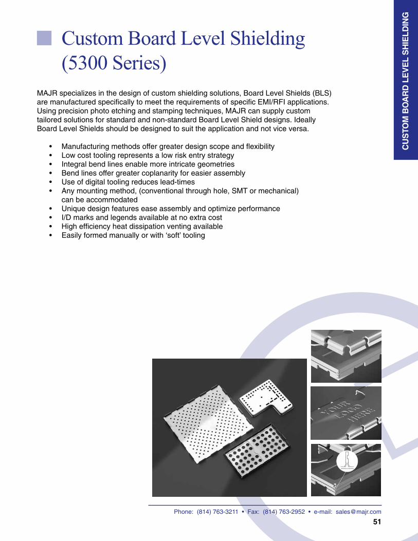
51
Custom Board Level Shielding (5300 Series)
MAJR specializes in the design of custom shielding solutions, Board Level Shields (BLS) are manufactured specifically to meet the requirements of specific EMI/RFI applications. Using precision photo etching and stamping techniques, MAJR can supply custom tailored solutions for standard and non-standard Board Level Shield designs. Ideally Board Level Shields should be designed to suit the application and not vice versa.
• Manufacturing methods offer greater design scope and flexibility• Low cost tooling represents a low risk entry strategy• Integral bend lines enable more intricate geometries• Bend lines offer greater coplanarity for easier assembly• Use of digital tooling reduces lead-times• Any mounting method, (conventional through hole, SMT or mechanical)
can be accommodated• Unique design features ease assembly and optimize performance• I/D marks and legends available at no extra cost• High efficiency heat dissipation venting available• Easily formed manually or with ‘soft’ tooling
CU
STO
M B
OA
RD
LE
VE
L S
HIE
LDIN
G
Phone: (814) 763-3211 • Fax: (814) 763-2952 • e-mail: [email protected]
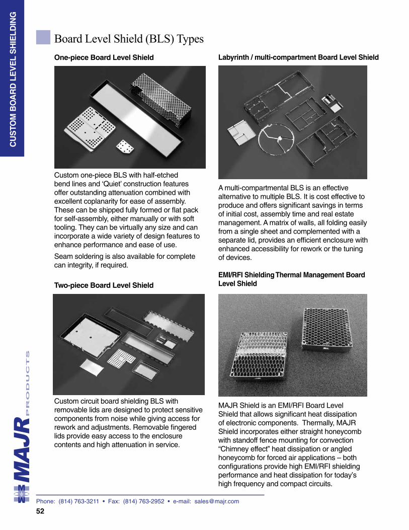
Phone: (814) 763-3211 • Fax: (814) 763-2952 • e-mail: [email protected]
52
CU
STO
M B
OA
RD
LE
VE
L S
HIE
LDIN
G
Board Level Shield (BLS) Types
One-piece Board Level Shield
Custom one-piece BLS with half-etched bend lines and ‘Quiet’ construction features offer outstanding attenuation combined with excellent coplanarity for ease of assembly. These can be shipped fully formed or flat pack for self-assembly, either manually or with soft tooling. They can be virtually any size and can incorporate a wide variety of design features to enhance performance and ease of use.
Seam soldering is also available for complete can integrity, if required.
Two-piece Board Level Shield
Custom circuit board shielding BLS with removable lids are designed to protect sensitive components from noise while giving access for rework and adjustments. Removable fingered lids provide easy access to the enclosure contents and high attenuation in service.
Labyrinth / multi-compartment Board Level Shield
A multi-compartmental BLS is an effective alternative to multiple BLS. It is cost effective to produce and offers significant savings in terms of initial cost, assembly time and real estate management. A matrix of walls, all folding easily from a single sheet and complemented with a separate lid, provides an efficient enclosure with enhanced accessibility for rework or the tuning of devices.
EMI/RFI Shielding Thermal Management Board Level Shield
MAJR Shield is an EMI/RFI Board Level Shield that allows significant heat dissipation of electronic components. Thermally, MAJR Shield incorporates either straight honeycomb with standoff fence mounting for convection “Chimney effect” heat dissipation or angled honeycomb for forced air applications – both configurations provide high EMI/RFI shielding performance and heat dissipation for today’s high frequency and compact circuits.
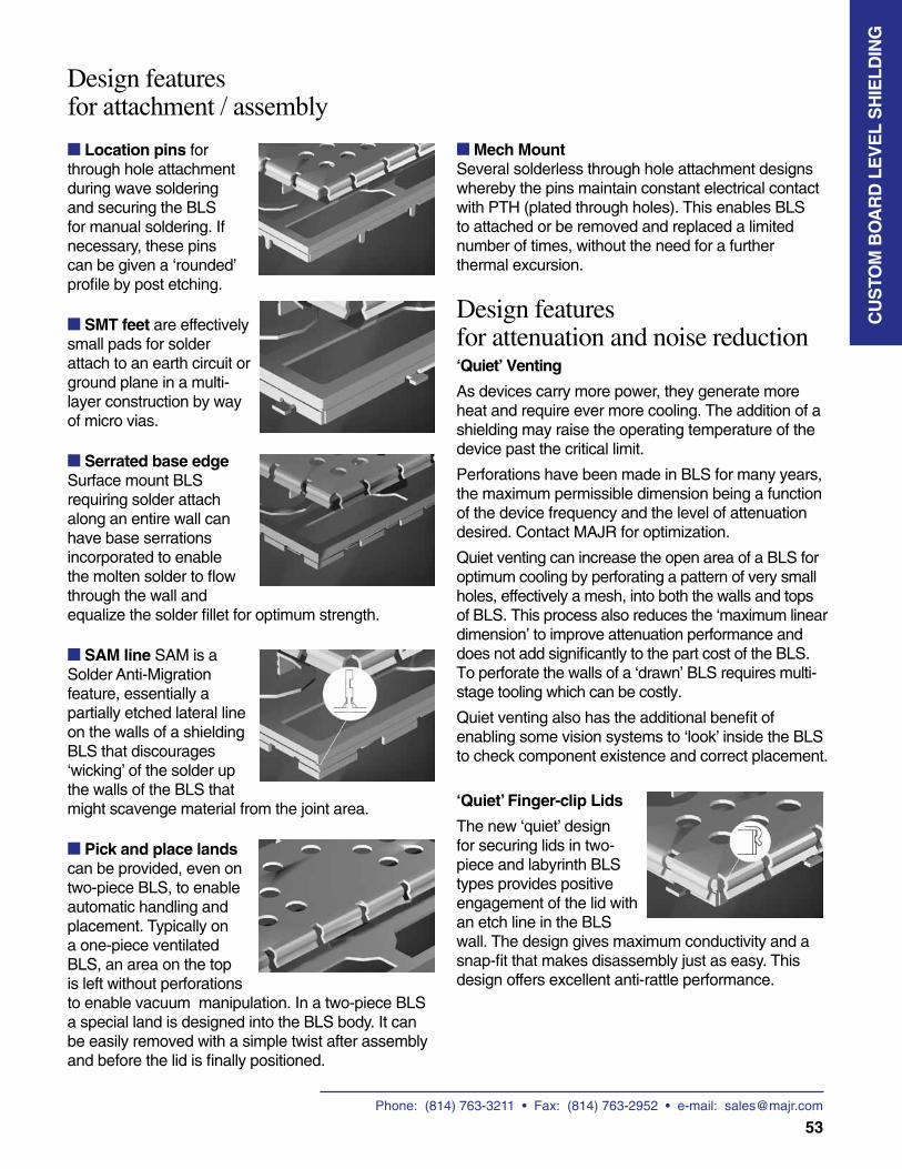
Phone: (814) 763-3211 • Fax: (814) 763-2952 • e-mail: [email protected]
53
CU
STO
M B
OA
RD
LE
VE
L S
HIE
LDIN
G
■ Mech MountSeveral solderless through hole attachment designs whereby the pins maintain constant electrical contact with PTH (plated through holes). This enables BLS to attached or be removed and replaced a limited number of times, without the need for a further thermal excursion.
Design featuresfor attenuation and noise reduction‘Quiet’ Venting
As devices carry more power, they generate more heat and require ever more cooling. The addition of a shielding may raise the operating temperature of the device past the critical limit.
Perforations have been made in BLS for many years, the maximum permissible dimension being a function of the device frequency and the level of attenuation desired. Contact MAJR for optimization.
Quiet venting can increase the open area of a BLS for optimum cooling by perforating a pattern of very small holes, effectively a mesh, into both the walls and tops of BLS. This process also reduces the ‘maximum linear dimension’ to improve attenuation performance and does not add significantly to the part cost of the BLS. To perforate the walls of a ‘drawn’ BLS requires multi-stage tooling which can be costly.
Quiet venting also has the additional benefit of enabling some vision systems to ‘look’ inside the BLS to check component existence and correct placement.
‘Quiet’ Finger-clip Lids
The new ‘quiet’ design for securing lids in two-piece and labyrinth BLS types provides positive engagement of the lid with an etch line in the BLS wall. The design gives maximum conductivity and a snap-fit that makes disassembly just as easy. This design offers excellent anti-rattle performance.
Design featuresfor attachment / assembly
■ Location pins for through hole attachment during wave soldering and securing the BLS for manual soldering. If necessary, these pins can be given a ‘rounded’ profile by post etching.
■ SMT feet are effectively small pads for solder attach to an earth circuit or ground plane in a multi-layer construction by way of micro vias.
■ Serrated base edge Surface mount BLS requiring solder attach along an entire wall can have base serrations incorporated to enable the molten solder to flow through the wall and equalize the solder fillet for optimum strength.
■ SAM line SAM is a Solder Anti-Migration feature, essentially a partially etched lateral line on the walls of a shielding BLS that discourages ‘wicking’ of the solder up the walls of the BLS that might scavenge material from the joint area.
■ Pick and place lands can be provided, even on two-piece BLS, to enable automatic handling and placement. Typically on a one-piece ventilated BLS, an area on the top is left without perforations to enable vacuum manipulation. In a two-piece BLS a special land is designed into the BLS body. It can be easily removed with a simple twist after assembly and before the lid is finally positioned.
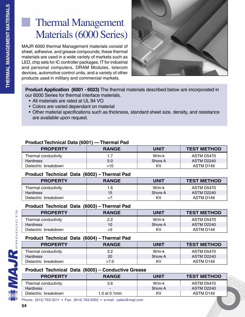
Phone: (814) 763-3211 • Fax: (814) 763-2952 • e-mail: [email protected]
54
Thermal Management Materials (6000 Series)
MAJR 6000 thermal Management materials consist of sheet, adhesive, and grease compounds; these thermal materials are used in a wide variety of markets such as LED, chip sets for IC controller packages, IT for industrial and personal computers, DRAM Modules, telecom devices, automotive control units, and a variety of other products used in military and commercial markets.
Product Technical Data (6001) — Thermal PadUNITRANGE TEST METHODPROPERTY
Thermal conductivity 1.7 W/m-k ASTM D5470Hardness 5.0 Shore A ASTM D2240Dielectric breakdown >10 KV ASTM D149
Product Technical Data (6004) – Thermal PadUNITRANGE TEST METHODPROPERTY
Thermal conductivity 3.2 W/m-k ASTM D5470Hardness 20 Shore A ASTM D2240Dielectric breakdown >7.0 KV ASTM D149
Product Technical Data (6003) – Thermal PadUNITRANGE TEST METHODPROPERTY
Thermal conductivity 2.2 W/m-k ASTM D5470Hardness 10 Shore A ASTM D2240Dielectric breakdown >5 KV ASTM D149
Product Technical Data (6002) – Thermal PadUNITRANGE TEST METHODPROPERTY
Thermal conductivity 1.6 W/m-k ASTM D5470Hardness 15 Shore A ASTM D2240Dielectric breakdown >7 KV ASTM D149
THE
RM
AL
MA
NA
GE
ME
NT
MA
TER
IALS
Product Application (6001 - 6023) The thermal materials described below are incorporated in our 6000 Series for thermal interface materials.
• All materials are rated at UL 94 VO• Colors are varied dependant on material• Other material specifications such as thickness, standard sheet size, density, and resistance
are available upon request.
Product Technical Data (6005) – Conductive GreaseUNITRANGE TEST METHODPROPERTY
Thermal conductivity 3.6 W/m-k ASTM D5470Hardness - Shore A ASTM D2240Dielectric breakdown 1.0 at 0.1mm KV ASTM D149
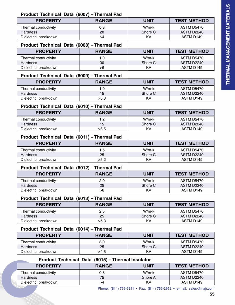
Phone: (814) 763-3211 • Fax: (814) 763-2952 • e-mail: [email protected]
55
Product Technical Data (6007) – Thermal PadUNITRANGE TEST METHODPROPERTY
Thermal conductivity 0.8 W/m-k ASTM D5470Hardness 20 Shore C ASTM D2240Dielectric breakdown >4 KV ASTM D149
Product Technical Data (6009) – Thermal PadUNITRANGE TEST METHODPROPERTY
Thermal conductivity 1.0 W/m-k ASTM D5470Hardness 15 Shore C ASTM D2240Dielectric breakdown >6.3 KV ASTM D149
Product Technical Data (6011) – Thermal PadUNITRANGE TEST METHODPROPERTY
Thermal conductivity 1.5 W/m-k ASTM D5470Hardness 25 Shore C ASTM D2240Dielectric breakdown >5.2 KV ASTM D149
Product Technical Data (6014) – Thermal PadUNITRANGE TEST METHODPROPERTY
Thermal conductivity 3.0 W/m-k ASTM D5470Hardness 25 Shore C ASTM D2240Dielectric breakdown >4.8 KV ASTM D149
Product Technical Data (6008) – Thermal PadUNITRANGE TEST METHODPROPERTY
Thermal conductivity 1.0 W/m-k ASTM D5470Hardness 30 Shore C ASTM D2240Dielectric breakdown >6 KV ASTM D149
Product Technical Data (6010) – Thermal PadUNITRANGE TEST METHODPROPERTY
Thermal conductivity 1.2 W/m-k ASTM D5470Hardness 15 Shore C ASTM D2240Dielectric breakdown >6.5 KV ASTM D149
Product Technical Data (6013) – Thermal PadUNITRANGE TEST METHODPROPERTY
Thermal conductivity 2.5 W/m-k ASTM D5470Hardness 25 Shore C ASTM D2240Dielectric breakdown >5.3 KV ASTM D149
Product Technical Data (6012) – Thermal PadUNITRANGE TEST METHODPROPERTY
Thermal conductivity 2.0 W/m-k ASTM D5470Hardness 25 Shore C ASTM D2240Dielectric breakdown >6 KV ASTM D149
THE
RM
AL
MA
NA
GE
ME
NT
MA
TER
IALS
Product Technical Data (6015) – Thermal InsulatorUNITRANGE TEST METHODPROPERTY
Thermal conductivity 0.8 W/m-k ASTM D5470Hardness 75 Shore A ASTM D2240Dielectric breakdown >4 KV ASTM D149
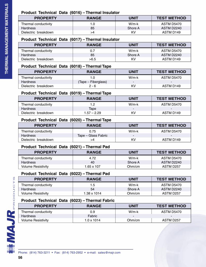
Phone: (814) 763-3211 • Fax: (814) 763-2952 • e-mail: [email protected]
56
THE
RM
AL
MA
NA
GE
ME
NT
MA
TER
IALS
Product Technical Data (6016) – Thermal InsulatorUNITRANGE TEST METHODPROPERTY
Thermal conductivity 1.0 W/m-k ASTM D5470Hardness 85 Shore A ASTM D2240Dielectric breakdown >4 KV ASTM D149
Product Technical Data (6018) – Thermal TapeUNITRANGE TEST METHODPROPERTY
Thermal conductivity 1.0 W/m-k ASTM D5470Hardness (Tape – Fiberglass) - -Dielectric breakdown 2 - 6 KV ASTM D149
Product Technical Data (6020) – Thermal TapeUNITRANGE TEST METHODPROPERTY
Thermal conductivity 0.75 W/m-k ASTM D5470Hardness Tape – Glass Fabric - -Dielectric breakdown >4 KV ASTM D149
Product Technical Data (6023) – Thermal FabricUNITRANGE TEST METHODPROPERTY
Thermal conductivity 0.9 W/m-k ASTM D5470Hardness Fabric - -Volume Resistivity 1.0 x 10¹⁴ Ohm/cm ASTM D257
Product Technical Data (6017) – Thermal InsulatorUNITRANGE TEST METHODPROPERTY
Thermal conductivity 0.7 W/m-k ASTM D5470Hardness 85 Shore A ASTM D2240Dielectric breakdown >6.5 KV ASTM D149
Product Technical Data (6019) – Thermal TapeUNITRANGE TEST METHODPROPERTY
Thermal conductivity 1.2 W/m-k ASTM D5470Hardness Tape - -Dielectric breakdown 1.57 – 2.29 KV ASTM D149
Product Technical Data (6022) – Thermal PadUNITRANGE TEST METHODPROPERTY
Thermal conductivity 1.5 W/m-k ASTM D5470Hardness 54 Shore A ASTM D2240Volume Resistivity 1.38 x 10¹⁴ Ohm/cm ASTM D257
Product Technical Data (6021) – Thermal PadUNITRANGE TEST METHODPROPERTY
Thermal conductivity 4.72 W/m-k ASTM D5470Hardness 40 Shore A ASTM D2240Volume Resistivity 1.65 x 10⁷ Ohm/cm ASTM D257
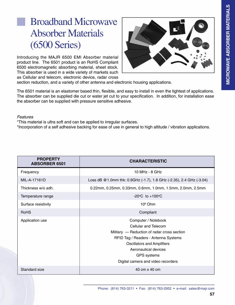
Phone: (814) 763-3211 • Fax: (814) 763-2952 • e-mail: [email protected]
57
MIC
RO
WA
VE
AB
SO
RB
ER
MA
TER
IALS
Broadband Microwave Absorber Materials (6500 Series)
Introducing the MAJR 6500 EMI Absorber material product line. The 6501 product is an RoHS Compliant 6500 electromagnetic absorbing material, sheet stock. This absorber is used in a wide variety of markets such as Cellular and telecom, electronic device, radar cross section reduction, and a variety of other antenna and electronic housing applications.
The 6501 material is an elastomer based thin, flexible, and easy to install in even the tightest of applications. The absorber can be supplied die cut or water jet cut to your specification. In addition, for installation ease the absorber can be supplied with pressure sensitive adhesive.
Features*This material is ultra soft and can be applied to irregular surfaces. *Incorporation of a self adhesive backing for ease of use in general to high altitude / vibration applications.
CHARACTERISTICPROPERTYABSORBER 6501
Frequency 10 MHz - 8 GHz
MIL-A-17161D Loss dB @1.0mm thk: 0.9GHz (-1.7), 1.8 GHz (-2.35), 2.4 GHz (-3.04)
Thickness w/o adh. 0.22mm, 0.25mm, 0.33mm, 0.6mm, 1.0mm, 1.5mm, 2.0mm, 2.5mm
Temperature range -20oC to +100oC
Surface resistivity 106 Ohm
RoHS Compliant
Application use Computer / Notebook
Cellular and Telecom
Military — Reduction of radar cross section
RFID Tag / Readers - Antenna Systems
Oscillators and Amplifiers
Aeronautical devices
GPS systems
Digital camera and video recorders
Standard size 40 cm x 40 cm

Phone: (814) 763-3211 • Fax: (814) 763-2952 • e-mail: [email protected]
58
Ferrites (7000 Series)
Flat Cable Suppression Core (FP Type)
Split ferrites for EMI suppression on flat cable assemblies.• Internal floppy disk and hard disk ribbon cables.• Internal ribbon cables between circuit boards and data connectors.• Internal ribbon cables with 8, 16, 32 or 64-bit digital signal busses.
Flat Cable Suppression Cores (FS Type)
Rectangular solid ferrites for EMI suppression on flat cable assemblies.• Internal floppy disk ribbon cables.• Internal ribbon cables between circuit boards and data connectors.• Internal ribbon cables with 8, 16, 32 or 64-bit digital signal busses.
Round Cable Suppression Core (KCF Type)
Enclosures for channel-type EMI-suppressor snaps.• Internal and external power cables.• Internal cables between PC boards and data connectors.
Round Cable Suppression Cores (RC Type)
Enclosures for channel-type EMI-suppressor snaps.• Internal and external power cables.• Internal cables between PC boards and data connectors.
Connector Suppressor Elements (FD Type)
EMI suppression for connectors and dual in-line integrated circuits.• 9, 15, 25 and 37 pin subminiature “D” connectors.
FE
RR
ITE
S
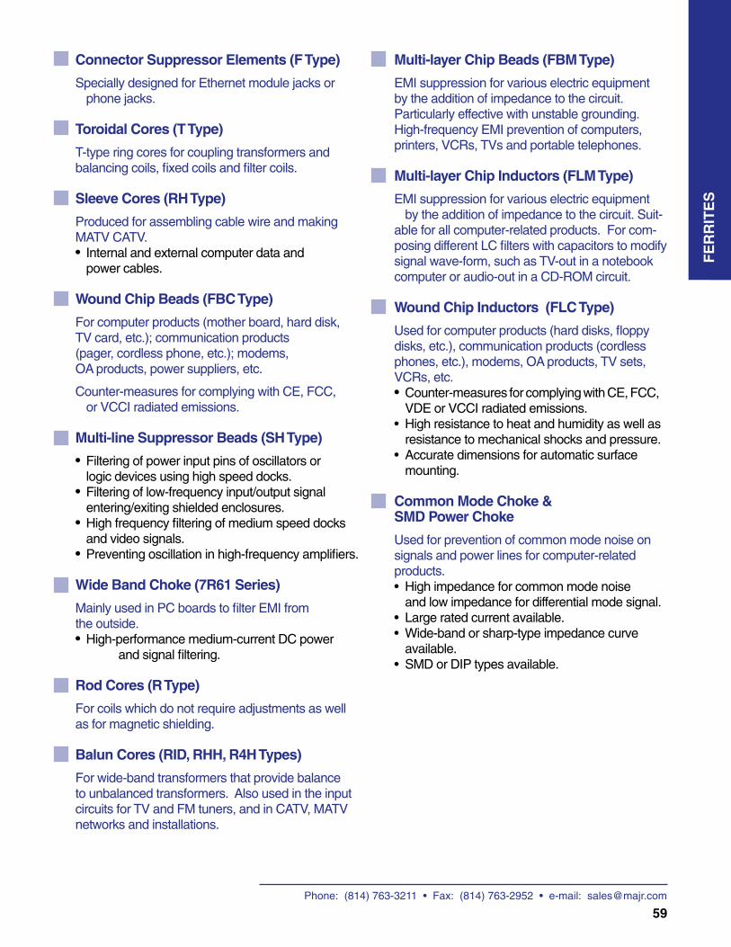
Phone: (814) 763-3211 • Fax: (814) 763-2952 • e-mail: [email protected]
59
FE
RR
ITE
S
Connector Suppressor Elements (F Type)
Specially designed for Ethernet module jacks or phone jacks.
Toroidal Cores (T Type)
T-type ring cores for coupling transformers and balancing coils, fixed coils and filter coils.
Sleeve Cores (RH Type)
Produced for assembling cable wire and making MATV CATV.• Internal and external computer data and power cables.
Wound Chip Beads (FBC Type)
For computer products (mother board, hard disk, TV card, etc.); communication products (pager, cordless phone, etc.); modems, OA products, power suppliers, etc.
Counter-measures for complying with CE, FCC, or VCCI radiated emissions.
Multi-line Suppressor Beads (SH Type)
• Filtering of power input pins of oscillators or logic devices using high speed docks.• Filtering of low-frequency input/output signal entering/exiting shielded enclosures.• High frequency filtering of medium speed docks and video signals.• Preventing oscillation in high-frequency amplifiers.
Wide Band Choke (7R61 Series)
Mainly used in PC boards to filter EMI from the outside.• High-performance medium-current DC power and signal filtering.
Rod Cores (R Type)
For coils which do not require adjustments as well as for magnetic shielding.
Balun Cores (RID, RHH, R4H Types)
For wide-band transformers that provide balance to unbalanced transformers. Also used in the input circuits for TV and FM tuners, and in CATV, MATV networks and installations.
Multi-layer Chip Beads (FBM Type)
EMI suppression for various electric equipment by the addition of impedance to the circuit.Particularly effective with unstable grounding.High-frequency EMI prevention of computers, printers, VCRs, TVs and portable telephones.
Multi-layer Chip Inductors (FLM Type)
EMI suppression for various electric equipment by the addition of impedance to the circuit. Suit-able for all computer-related products. For com-posing different LC filters with capacitors to modify signal wave-form, such as TV-out in a notebook computer or audio-out in a CD-ROM circuit.
Wound Chip Inductors (FLC Type)
Used for computer products (hard disks, floppy disks, etc.), communication products (cordless phones, etc.), modems, OA products, TV sets, VCRs, etc.• Counter-measures for complying with CE, FCC, VDE or VCCI radiated emissions.• High resistance to heat and humidity as well as resistance to mechanical shocks and pressure. • Accurate dimensions for automatic surface mounting.
Common Mode Choke & SMD Power Choke
Used for prevention of common mode noise on signals and power lines for computer-related products.• High impedance for common mode noise and low impedance for differential mode signal.• Large rated current available.• Wide-band or sharp-type impedance curve available.• SMD or DIP types available.
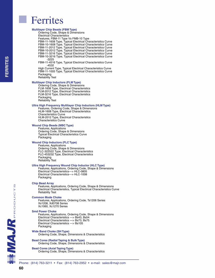
Phone: (814) 763-3211 • Fax: (814) 763-2952 • e-mail: [email protected]
60
FerritesMultilayer Chip Beads (FBM Type)
Ordering Code, Shape & Dimensions Electrical Characteristics Features, FBM-11 Type Vs FMB-10 Type FBM-11-1608 Type, Typical Electrical Characteristics Curve FBM-10-1608 Type, Typical Electrical Characteristics Curve FBM-11-2012 Type, Typical Electrical Characteristics Curve FBM-10-2012 Type, Typical Electrical Characteristics Curve FBM-11-3216 Type, Typical Electrical Characteristics Curve FBM-10-3216 Type, Typical Electrical Characteristics Curve
-3225 FBM-11-4516 Type, Typical Electrical Characteristics Curve
-4532 High Current Type, Typical Electrical Characteristics Curve FBM-11-1005 Type, Typical Electrical Characteristics Curve Packaging Reliability Test
Multilayer Chip Inductors (FLM Type) Ordering Code, Shape & Dimensions FLM-1608 Type, Electrical Characteristics FLM-2012 Type, Electrical Characteristics FLM-3216 Type, Electrical Characteristics Packaging Reliability Test
Ultra High Frequency Multilayer Chip Inductors (HLM Type) Features, Ordering Code, Shape & Dimensions HLM-1608 Type, Electrical Characteristics Characteristics Curve HLM-2012 Type, Electrical Characteristics Characteristics Curve
Wound Chip Beads (MBC Type) Features, Applications Ordering Code, Shape & Dimensions Typical Electrical Characteristics Curve Packaging
Wound Chip Inductors (FLC Type) Features, Applications Ordering Code, Shape & Dimensions FLC-322522 Type, Electrical Characteristics FLC-453232 Type, Electrical Characteristics Packaging Reliability Test
Ultra High Frequency Wound Chip Inductor (HLC Type) Features, Applications, Ordering Code, Shape & Dimensions Electrical Characteristics—> HLC-0805 Electrical Characteristics—> HLC-1008 Packaging
Chip Bead Array Features, Applications, Ordering Code, Shape & Dimensions Electrical Characteristics, Typical Electrical Characteristics Curve Reliability Test
Common Mode Choke Features, Applications, Ordering Code, Ts1206 Series Xs1208, Xd0708 Series Xc1060, Xc1270 Series
Smd Power Choke Features, Applications, Ordering Code, Shape & Dimensions Electrical Characteristics —> Bs43, Bs54 Electrical Characteristics —> Bs73, Bs75 Electrical Characteristics —> Bs105 Packaging
Wide Band Choke (SH Type) Ordering Code, Shape, Dimensions & Characteristics
Bead Cores (Radial Taping & Bulk Type) Ordering Code, Shape, Dimensions & Characteristics
Bead Cores (Axial Taping Type) Ordering Code, Shape, Dimensions & Characteristics
FE
RR
ITE
S
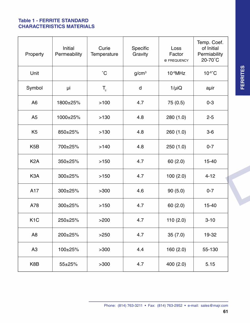
Phone: (814) 763-3211 • Fax: (814) 763-2952 • e-mail: [email protected]
61
FE
RR
ITE
S
Table 1 - FERRITE STANDARDCHARACTERISTICS MATERIALS
Temp. Coef. Initial Curie Specific Loss of Initial Property Permeability Temperature Gravity Factor Permiability @ FREQUENCY 20-70˚C
Unit ˚C g/cm3 10-6MHz 10-6˚C
Symbol µi Tc d 1/µiQ aµir
A6 1800±25% >100 4.7 75 (0.5) 0-3
A5 1000±25% >130 4.8 280 (1.0) 2-5
K5 850±25% >130 4.8 260 (1.0) 3-6
K5B 700±25% >140 4.8 250 (1.0) 0-7
K2A 350±25% >150 4.7 60 (2.0) 15-40
K3A 300±25% >150 4.7 100 (2.0) 4-12
A17 300±25% >300 4.6 90 (5.0) 0-7
A78 300±25% >150 4.7 60 (2.0) 15-40
K1C 250±25% >200 4.7 110 (2.0) 3-10
A8 200±25% >250 4.7 35 (7.0) 19-32
A3 100±25% >300 4.4 160 (2.0) 55-130
K8B 55±25% >300 4.7 400 (2.0) 5.15
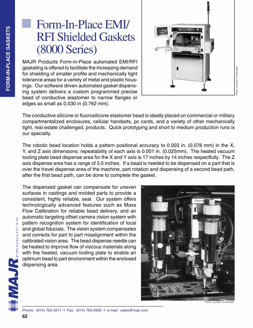
Phone: (814) 763-3211 • Fax: (814) 763-2952 • e-mail: [email protected]
62
Form-In-Place EMI/RFI Shielded Gaskets (8000 Series)
MAJR Products Form-in-Place automated EMI/RFI gasketing is offered to facilitate the increasing demand for shielding of smaller profile and mechanically tight tolerance areas for a variety of metal and plastic hous-ings. Our software driven automated gasket dispens-ing system delivers a custom programmed precise bead of conductive elastomer to narrow flanges or edges as small as 0.030 in (0.762 mm).
The conductive silicone or fluorosilicone elastomer bead is ideally placed on commercial or military compartmentalized enclosures, cellular handsets, pc cards, and a variety of other mechanically tight, real estate challenged, products. Quick prototyping and short to medium production runs is our specialty.
The robotic bead location holds a pattern positional accuracy to 0.003 in. (0.076 mm) in the X, Y, and Z axis dimensions; repeatability of each axis is 0.001 in. (0.025mm). The heated vacuum tooling plate bead dispense area for the X and Y axis is 17 inches by 14 inches respectfully. The Z axis dispense area has a range of 3.5 inches. If a bead is needed to be dispensed on a part that is over the travel dispense area of the machine, part rotation and dispensing of a second bead path, after the first bead path, can be done to complete the gasket.
The dispensed gasket can compensate for uneven surfaces in castings and molded parts to provide a consistent, highly reliable, seal. Our system offers technologically advanced features such as Mass Flow Calibration for reliable bead delivery, and an automatic targeting offset camera vision system with pattern recognition system for identification of local and global fiducials. The vision system compensates and corrects for part to part misalignment within the calibrated vision area. The bead dispense needle can be heated to improve flow of viscous materials along with the heated, vacuum tooling plate to enable an optimum bead to part environment within the enclosed dispensing area.
FO
RM
-IN
-PL
AC
E G
AS
KE
TS
Photo courtesy of Asymtek
Pho
to c
ourt
esy
of A
sym
tek
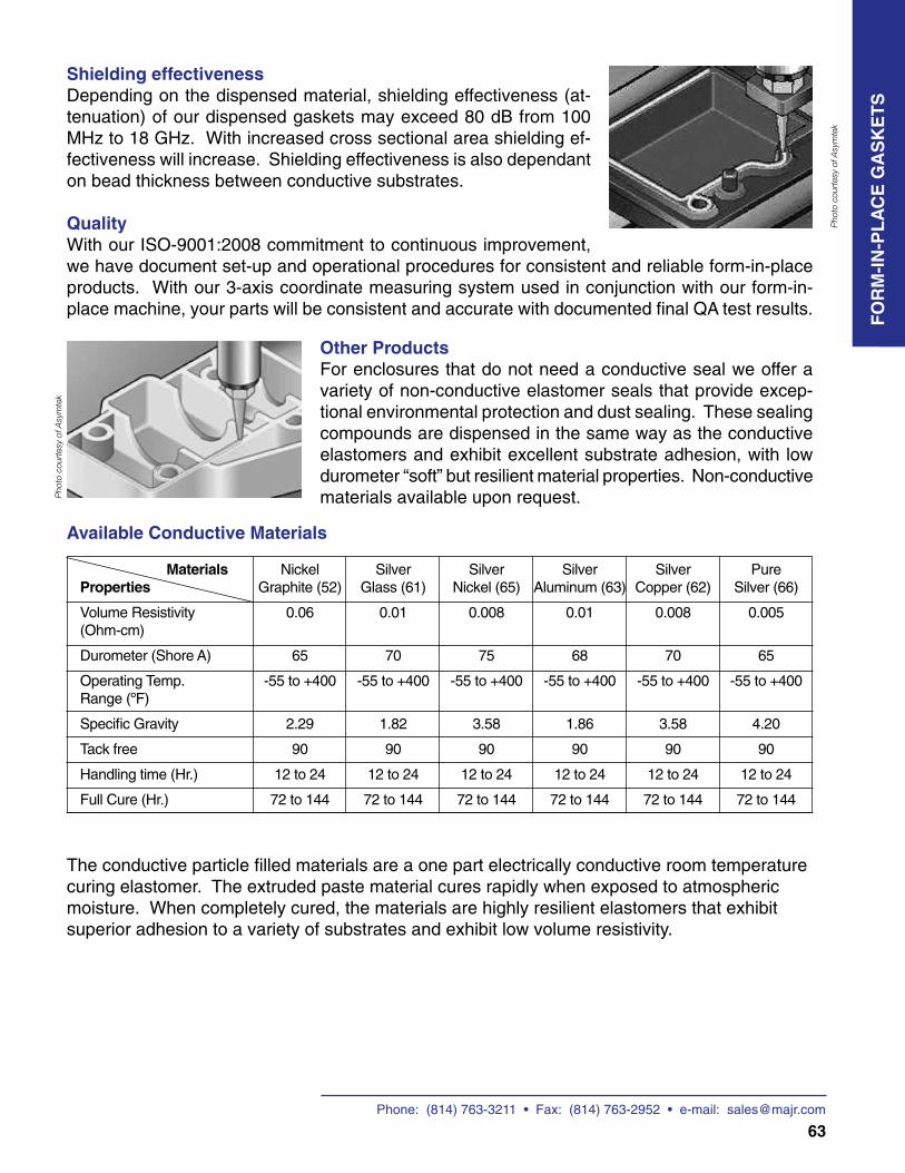
Phone: (814) 763-3211 • Fax: (814) 763-2952 • e-mail: [email protected]
63
Photo courtesy of Asymtek
Available Conductive Materials
Materials Nickel Silver Silver Silver Silver Pure Properties Graphite (52) Glass (61) Nickel (65) Aluminum (63) Copper (62) Silver (66)
Volume Resistivity 0.06 0.01 0.008 0.01 0.008 0.005 (Ohm-cm)
Durometer (Shore A) 65 70 75 68 70 65
Operating Temp. -55 to +400 -55 to +400 -55 to +400 -55 to +400 -55 to +400 -55 to +400 Range (ºF)
Specific Gravity 2.29 1.82 3.58 1.86 3.58 4.20
Tack free 90 90 90 90 90 90
Handling time (Hr.) 12 to 24 12 to 24 12 to 24 12 to 24 12 to 24 12 to 24
Full Cure (Hr.) 72 to 144 72 to 144 72 to 144 72 to 144 72 to 144 72 to 144
Shielding effectiveness Depending on the dispensed material, shielding effectiveness (at-tenuation) of our dispensed gaskets may exceed 80 dB from 100 MHz to 18 GHz. With increased cross sectional area shielding ef-fectiveness will increase. Shielding effectiveness is also dependant on bead thickness between conductive substrates.
QualityWith our ISO-9001:2008 commitment to continuous improvement, we have document set-up and operational procedures for consistent and reliable form-in-place products. With our 3-axis coordinate measuring system used in conjunction with our form-in-place machine, your parts will be consistent and accurate with documented final QA test results.
Other ProductsFor enclosures that do not need a conductive seal we offer a variety of non-conductive elastomer seals that provide excep-tional environmental protection and dust sealing. These sealing compounds are dispensed in the same way as the conductive elastomers and exhibit excellent substrate adhesion, with low durometer “soft” but resilient material properties. Non-conductive materials available upon request.
The conductive particle filled materials are a one part electrically conductive room temperature curing elastomer. The extruded paste material cures rapidly when exposed to atmospheric moisture. When completely cured, the materials are highly resilient elastomers that exhibit superior adhesion to a variety of substrates and exhibit low volume resistivity.
Pho
to c
ourt
esy
of A
sym
tek
Pho
to c
ourt
esy
of A
sym
tek
FO
RM
-IN
-PL
AC
E G
AS
KE
TS

Phone: (814) 763-3211 • Fax: (814) 763-2952 • e-mail: [email protected]
64
MAJR Products offers Mechanical and EMC consulting services to our customers that need to bring their product from design concept through testing compliance to full production or any stage in between. We are always available by phone and email to assist in technical questions and design concerns. Telecom and on site consulting up to 2 hours is provided completely free to the customer and after that is available at an hourly fee or can be quoted per diem or by project. We can assist in meeting MIL-STD 461 and other military or commercial standards.
Mechanical Engineering – Biography of Bill Spencer
Mr. Spencer is the Vice President of Mechanical Engineering at MAJR Products Corporation. He is responsible for overseeing the generation of all internal production drawings for manufacturing as well as the interpretation and conversion of customer drawings to mechanically sound renderings for that purpose. He oversees all product estimating for quotation of new parts and existing designs and acts as a mechanical interface with customers for EMI/RFI shielding design. He is responsible for calibration for ISO-9001 and documentation for job traveler and all drawing revisions for production.
Bill holds a B.S. degree in Mechanical Engineering from Penn State University and has been a Mechanical Engineer since 1975. He has experience in equipment design
and start-up and has been involved with shielding components since 1991. He has participated in anechoic chamber testing for EMI/RFI shielding for various honeycomb vent panels and has previously served as production manager for 13 years. Bill has literally taken thousands of paper concepts through to reality as viable Electromechanically sound shielding parts.
Electrical / EMC Engineering – Biography of Michael Oliver
Mr. Michael J. Oliver is Vice President of Electrical / EMC Engineering at MAJR Products Corporation in charge of customer EMC design and consulting, new product development, and is the ISO-9001:2008 management representative. His expertise is in EMI/RFI shielding technology with a background in electronics, military shelter electrical EMC systems, and high power antenna / radome design.
Mr. Oliver has over 20 years of experience in Electromagnetic Compatibility/Electromagnetic Environmental Effects for military and commercial products / systems. He holds three patents on EMC shielding and thermal management devices. He has authored numerous publications and white papers on the design and test of electromagnetic shielding products along with military antenna/radome test methodology
standards. He has performed open and anechoic chamber radiated tests to military standards utilizing various radiated test systems.
Mr. Oliver is a Senior Member of IEEE and currently serves on the EMC Society Board of Directors. He is Chairman of the IEEE EMC Pittsburgh Chapter, Co-Chairman of the SAE AE4 Electromagnetic Compatibility E3 Committee, and a member of the IEEE EMC Standards Advisory Coordination Committee (SACCom) and “dB society”. Mr. Oliver is Chairman of the 2012 IEEE EMC Symposium to be held in Pittsburgh PA.
EMC Consulting (9000 Series)
EM
C C
ON
SU
LTIN
G
Phone: (814) 763-3211 • Fax: (814) 763-2952 • e-mail: [email protected]
69
Assembly and Sub-Assembly Here at HSG we know that business success depends on finding the right partners, specifically the right manufacturer. Our company has been in manufacturing for over 30 years, providing products and services to customers in many industries around the globe. We have developed the tools necessary for accurate fabrication, testing, inspection, packing and shipping of high quality product. Having the experience of working with customers in a variety of industries gives us the flexibility that’s needed to bring your specific design to market in a timely and complete fashion. Consider the areas below in choosing HSG as your manufacturing partner.
ConsultingWith close to a century of combined manufacturing experience we can guide our customers through the most challenging requirements. While we have helped customers solve their electrical and mechanical design problems for years we know that good advice begins with the ability to listen and understand the client’s problem. Because of this we offer on-your-site consulting services to ensure that all your requirements are satisfied.
Engineering and DesignOur Engineering department has brought literally thousands of EMC and mechanical designs to life. The right experience and willingness to work through challenging requirements is what you can expect from HSG when your product needs to move from a design to the market.
Quality FocusYou must have confidence that your supplier can provide a quality product. HSG applies Total Quality Management throughout our operations, and we have been registered to ISO 9001:2008 since the second quarter of 2005. Moreover, quality reliability is reinforced with such in-house resources as a coordinate measuring machine (CMM) for machine set-up verification and final inspection of product that leave our facility. Computer generated reports as well as digital photos of parts in process during inspection are also available upon customer request.
Areas of Core CompetencyMetal Fabrication: Cutting (variety of methods including water jet machine), notching, drilling and fixturing, grinding, bending, punching as well as welding, soldering and other methods of joining.Gasketing: Several presses for die-cutting of a wide variety of substrate materials for gaskets, mechanical and chemical joining, work stations for close tolerance hand work, gask-o-mat machines for fabric over foam gasket construction, thousands of dies and variety of other tooling.Knitting: Machines for knitting of fine metal wire, drawing of wire, mechanical and chemical joining of knitted mesh and ability to knit over wide variety of core materials.Water Jet Cutting: Cutting of a variety of substrates in thicknesses of up to 6” on a 4’ by 8’ bed for quick turn rapid prototyping all the way through high volume production runs.Form-In-Place Gaskets: Close tolerance form-in-place gasketing machine can deposit fine beads of both conductive and non-conductive gasketing material directly on customer parts for quick turn or medium to large production runs.Assembly and Value Add: Being in manufacturing with the above core competencies has led to a number of jobs and situations in which HSG has partially assembled, assembled or done value adds to hundreds of customer parts over the years.
Contact UsTo find out more about our abilities to assist you with your design, compliance, quality, manufacturing and inspection contact a HSG sales representative today!
AS
SE
MB
LY / S
UB
-AS
SE
MB
LY
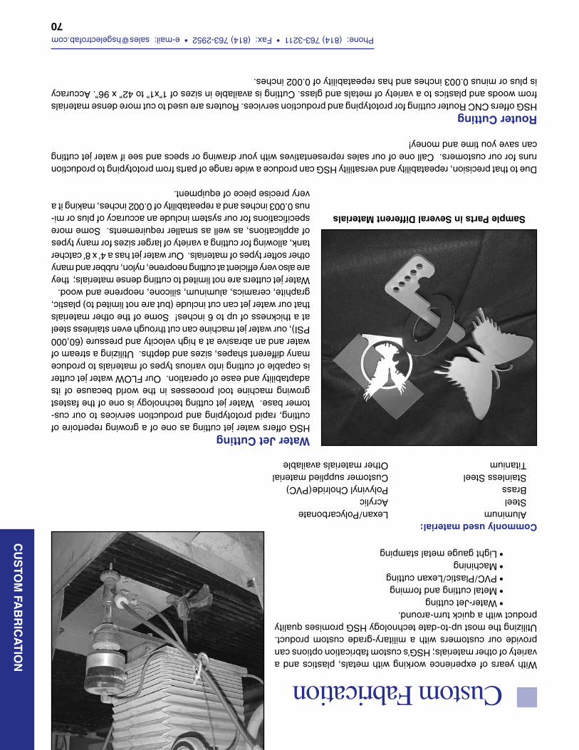
Phone: (814) 763-3211 • Fax: (814) 763-2952 • e-mail: [email protected]
70
Custom FabricationWith years of experience working with metals, plastics and a variety of other materials; HSG’s custom fabrication options can provide our customers with a military-grade custom product. Utilizing the most up-to-date technology HSG promises quality product with a quick turn-around. • Water-Jet cutting • Metal cutting and forming • PVC/Plastic/Lexan cutting • Machining • Light gauge metal stamping
Water Jet Cutting HSG offers water jet cutting as one of a growing repertoire of cutting, rapid prototyping and production services to our cus-tomer base. Water jet cutting technology is one of the fastest growing machine tool processes in the world because of its adaptability and ease of operation. Our FLOW water jet cutter is capable of cutting into various types of materials to produce many different shapes, sizes and depths. Utilizing a stream of water and an abrasive at a high velocity and pressure (60,000 PSI), our water jet machine can cut through even stainless steel at a thickness of up to 6 inches! Some of the other materials that our water jet can cut include (but are not limited to) plastic, graphite, ceramics, aluminum, silicone, neoprene and wood.Water jet cutters are not limited to cutting dense materials; they are also very efficient at cutting neoprene, nylon, rubber and many other softer types of materials. Our water jet has a 4’ x 8’ catcher tank, allowing for cutting a variety of larger sizes for many types of applications, as well as smaller requirements. Some more specifications for our system include an accuracy of plus or mi-nus 0.003 inches and a repeatability of 0.002 inches, making it a very precise piece of equipment.
Due to that precision, repeatability and versatility HSG can produce a wide range of parts from prototyping to production runs for our customers. Call one of our sales representatives with your drawing or specs and see if water jet cutting can save you time and money!
Router CuttingHSG offers CNC Router cutting for prototyping and production services. Routers are used to cut more dense materials from woods and plastics to a variety of metals and glass. Cutting is available in sizes of 1”x1” to 42” x 96”. Accuracy is plus or minus 0.003 inches and has repeatability of 0.002 inches.
Sample Parts in Several Different Materials
CU
STO
M FA
BR
ICA
TIO
N
Commonly used material: Aluminum Steel Brass Stainless Steel Titanium
Lexan/Polycarbonate Acrylic Polyvinyl Cholride(PVC) Customer supplied material Other materials available
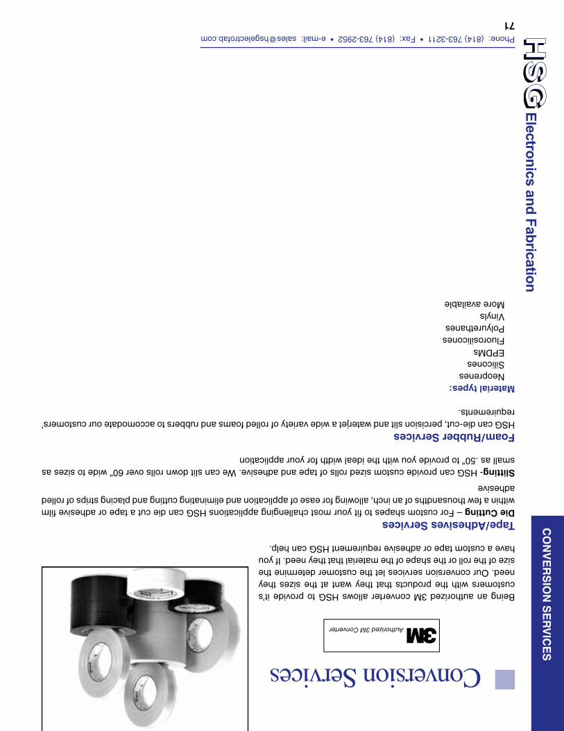
Phone: (814) 763-3211 • Fax: (814) 763-2952 • e-mail: [email protected]
71
CO
NV
ER
SIO
N S
ER
VIC
ESConversion Services
Being an authorized 3M converter allows HSG to provide it’s customers with the products that they want at the sizes they need. Our conversion services let the customer determine the size of the roll or the shape of the material that they need. If you have a custom tape or adhesive requirement HSG can help.
Tape/Adhesives ServicesDie Cutting – For custom shapes to fit your most challenging applications HSG can die cut a tape or adhesive film within a few thousandths of an inch, allowing for ease of application and eliminating cutting and placing strips of rolled adhesive
Slitting- HSG can provide custom sized rolls of tape and adhesive. We can slit down rolls over 60” wide to sizes as small as .50” to provide you with the ideal width for your application
Foam/Rubber ServicesHSG can die-cut, percision slit and waterjet a wide variety of rolled foams and rubbers to accomodate our customers’ requirements.
Material types: Neoprenes Silicones EPDMs Fluorosilicones Polyurethanes Vinyls More available
Authorized 3M Converter
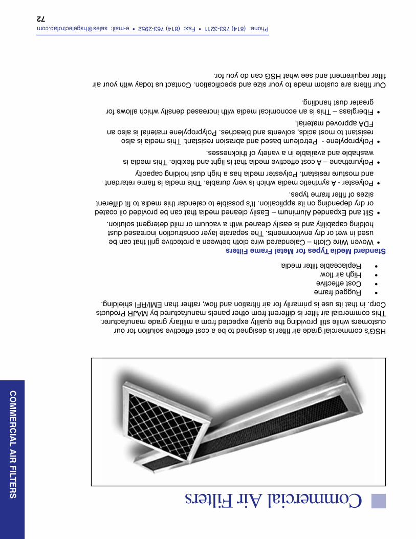
Phone: (814) 763-3211 • Fax: (814) 763-2952 • e-mail: [email protected]
72
CO
MM
ER
CIA
L A
IR F
ILTE
RS
HSG’s commercial grade air filter is designed to be a cost effective solution for our customers while still providing the quality expected from a military grade manufacturer. This commercial air filter is different from other panels manufactured by MAJR Products Corp. in that its use is primarily for air filtration and flow, rather than EMI/RFI shielding.
• Rugged frame • Cost effective • High air flow • Replaceable filter media
Standard Media Types for Metal Frame Filters• Woven Wire Cloth – Calendared wire cloth between a protective grill that can be
used in wet or dry environments. The separate layer construction increased dust holding capability and is easily cleaned with a vacuum or mild detergent solution.
• Slit and Expanded Aluminum – Easily cleaned media that can be provided oil coated or dry depending on its application. It’s possible to calendar this media to fit different sizes of filter frame types.
• Polyester - A synthetic media which is very durable. This media is flame retardant and mosture resistant. Polyester media has a high dust holding capacity
• Polyurethane – A cost effective media that is light and flexible. This media is washable and available in a variety of thicknesses.
• Polypropylene - Petroleum based and abrasion resistant. This media is also resistant to most acids, solvents and bleaches. Polypropylene material is also an FDA approved material.
• Fiberglass – This is an economical media with increased density which allows for greater dust handling.
Our filters are custom made to your size and specification. Contact us today with your air filter requirement and see what HSG can do you for.
Commercial Air Filters
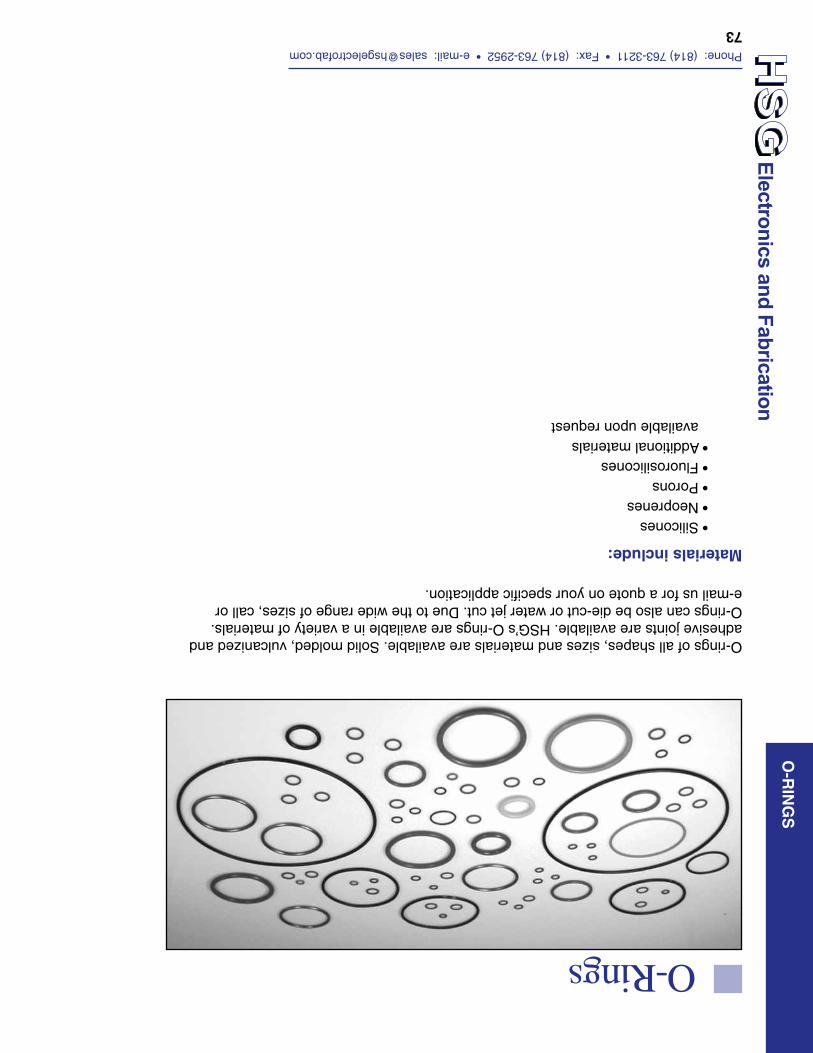
Phone: (814) 763-3211 • Fax: (814) 763-2952 • e-mail: [email protected]
73
O-R
ING
S
O-rings of all shapes, sizes and materials are available. Solid molded, vulcanized and adhesive joints are available. HSG’s O-rings are available in a variety of materials. O-rings can also be die-cut or water jet cut. Due to the wide range of sizes, call or e-mail us for a quote on your specific application.
O-Rings
• Silicones• Neoprenes• Porons• Fluorosilicones• Additional materials available upon request
Materials include:
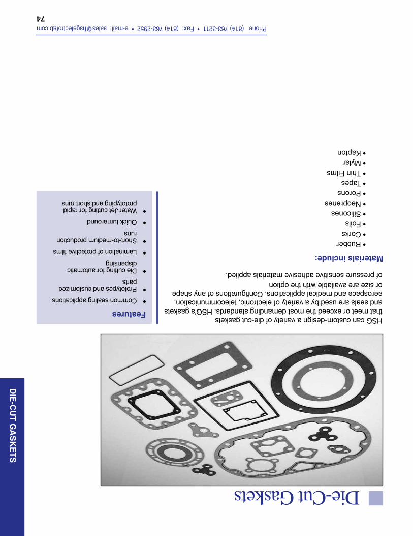
Phone: (814) 763-3211 • Fax: (814) 763-2952 • e-mail: [email protected]
74
DIE
-CU
T G
AS
KE
TS
Die-Cut Gaskets
Features
• Rubber• Corks• Foils• Silicones• Neoprenes• Porons• Tapes• Thin Films• Mylar• Kapton
HSG can custom-design a variety of die-cut gaskets that meet or exceed the most demanding standards. HSG’s gaskets and seals are used by a variety of electronic, telecommunication, aerospace and medical applications. Configurations of any shape or size are available with the option of pressure sensitive adhesive materials applied.
Materials include:
• Common sealing applications
• Prototypes and customized parts
• Die cutting for automatic dispensing
• Lamination of protective films
• Short-to-medium production runs
• Quick turnaround
• Water Jet cutting for rapid prototyping and short runs
HSG Electronics and Fabrication Products and Services
Gasket Fabrication • Services o Die Cutting o Water jet Cutting o Form-In-place o Vulcanization
• Type/Material o Silicones o Neoprenes o Porons o Closed and Open cell o Dust o EPDM o High Temperature o UL94 o Enclosure Gasketing NEMA IP65 * Other materials are available
upon request.
Air Filters (commercial) • Woven Wire Cloth • Slit and Expanded Aluminum • Foam
o Polyfoam o Reticulated Foam * Other materials are available upon request.
Conversion Services • Tape/Adhesives
o Die Cutting o Lamination o Slitting
• Foam o Die Cutting o Water jet Cutting
Custom Fabrication • Water jet cutting and router cutting • Metal cutting and forming • PVC/Plastic/Lexan cutting • Machining • Light gauge metal stamping
Authorized 3M Converter
17540 State Highway 198Saegertown, PA16433
Phone: (814) 763-3211Toll Free: (877) 625-7776
Fax: (814) 763-2952
web: www.hsgelectrofab.comemail: [email protected] division of MAJR Products Corp
ISO 9001 :2008 Registered • Veteran Owned Small Business • ITAR Registered
A division of MAJR Products Corp
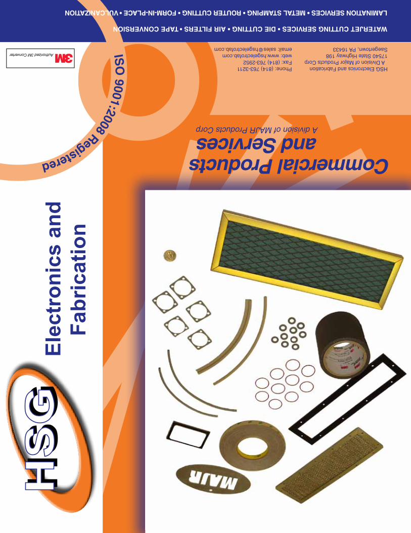
Commercial Products and Services A division of MAJR Products Corp
WATERJET CUTTING SERVICES • DIE CUTTING • AIR FILTERS • TAPE CONVERSION
LAMINATION SERVICES • METAL STAMPING • ROUTER CUTTING • FORM-IN-PLACE • VULCANIZATION
HSG Electronics and Fabrication A Division of Major Products Corp17540 State Highway 198Saegertown, PA 16433
Phone: (814) 763-3211Fax: (814) 763-2952web: www.hsgelectrofab.comemail: [email protected]
Authorized 3M Converter ISO
9001:2008 Registered
HS
GH
SG
Elec
tron
ics
and
Fabr
icat
ion