EMI/RFI Band Application System for M85049/128 Shield ... · These tools tension, bend, and cut the...
12
-
Upload
phungquynh -
Category
Documents
-
view
214 -
download
0
Transcript of EMI/RFI Band Application System for M85049/128 Shield ... · These tools tension, bend, and cut the...
DANIELS MANUFACTURING CORP., 526 THORPE ROAD, ORLANDO, FL 32824, USAPHONE (407) 855-6161 • FAX (407) 855-6884 • www.dmctools.com • E-MAIL: [email protected]
5/15 Banding Tools-SLCopyright © 2015 Daniels Manufacturing Corp. All Rights Reserved
EMI/RFI Band Application System for M85049/128 Shield Termination Bands
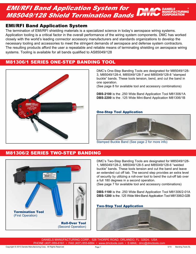
DMC’s One-Step Banding Tools are designated for M85049/128-3, M85049/128-4, M85049/128-7 and M85049/128-8 “stamped buckle” bands. These tools tension, bend, and cut the band in one operation. (See page 8 for available tool and accessory combinations)
DBS-2100 is the .250 Wide Band Application Tool M81306/1A DBS-2200 is the .125 Wide Mini-Band Application M81306/1B
One-Step Tool Application
Stamped Buckle Band (See page 2 for more info)
Two-Step Tool Application
The termination of EMI/RFI shielding materials is a specialized science in today’s aerospace wiring systems. Application tooling is a critical factor in the overall performance of the wiring system components. DMC has worked closely with the world’s leading connector accessory manufacturers and standards organizations to develop the necessary tooling and accessories to meet the stringent demands of aerospace and defense system contractors. The resulting products afford the user a repeatable and reliable means of terminating shielding on aerospace wiring systems. Tooling is available for all bands qualified to AS85049/128
DMC’s Two-Step Banding Tools are designated for M85049/128-1, M85049/128-2, M85049/128-5 and M85049/128-6 “welded buckle” bands. These tools tension and cut the band and leave an extended cut off tab. The second step provides an extra level of security by utilizing a roll-over tool to bend the cut-off tab over a full 180 degrees in a second operation. (See page 7 for available tool and accessory combinations)
DBS-1100 is the .250 Wide Band Application Tool M81306/2-01A DBS-1200 is the .125 Wide Mini-Band Application Tool M81306/2-02B
EMI/RFI Band Application System
M81306/1 SERIES ONE-STEP BANDING TOOL
M81306/2 SERIES TWO-STEP BANDING
Roll-Over Tool(Second Operation)
Termination Tool(First Operation)
Page 1
DANIELS MANUFACTURING CORP., 526 THORPE ROAD, ORLANDO, FL 32824, USAPHONE (407) 855-6161 • FAX (407) 855-6884 • www.dmctools.com • E-MAIL: [email protected]
5/15 Banding Tools-SL Copyright © 2015 Daniels Manufacturing Corp. All Rights Reserved
M85049/128 Band Configurations
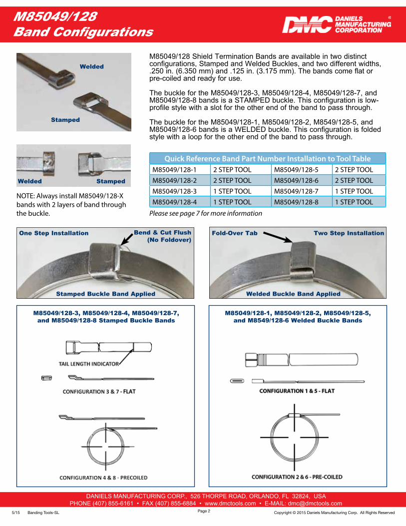
Stamped Buckle Band Applied
One Step Installation Bend & Cut Flush(No Foldover)
Welded Buckle Band Applied
M85049/128 Shield Termination Bands are available in two distinct configurations, Stamped and Welded Buckles, and two different widths, .250 in. (6.350 mm) and .125 in. (3.175 mm). The bands come flat or pre-coiled and ready for use.
The buckle for the M85049/128-3, M85049/128-4, M85049/128-7, and M85049/128-8 bands is a STAMPED buckle. This configuration is low-profile style with a slot for the other end of the band to pass through.
The buckle for the M85049/128-1, M85049/128-2, M8549/128-5, and M85049/128-6 bands is a WELDED buckle. This configuration is folded style with a loop for the other end of the band to pass through.
M85049/128-3, M85049/128-4, M85049/128-7, and M85049/128-8 Stamped Buckle Bands
M85049/128-1, M85049/128-2, M85049/128-5, and M8549/128-6 Welded Buckle Bands
Welded
Stamped
Welded Stamped
Quick Reference Band Part Number Installation to Tool TableM85049/128-1 2 STEP TOOL M85049/128-5 2 STEP TOOLM85049/128-2 2 STEP TOOL M85049/128-6 2 STEP TOOLM85049/128-3 1 STEP TOOL M85049/128-7 1 STEP TOOLM85049/128-4 1 STEP TOOL M85049/128-8 1 STEP TOOL
Please see page 7 for more information
NOTE: Always install M85049/128-X bands with 2 layers of band through the buckle.
Two Step InstallationFold-Over Tab
Page 2
DANIELS MANUFACTURING CORP., 526 THORPE ROAD, ORLANDO, FL 32824, USAPHONE (407) 855-6161 • FAX (407) 855-6884 • www.dmctools.com • E-MAIL: [email protected]
5/15 Banding Tools-SLCopyright © 2015 Daniels Manufacturing Corp. All Rights Reserved
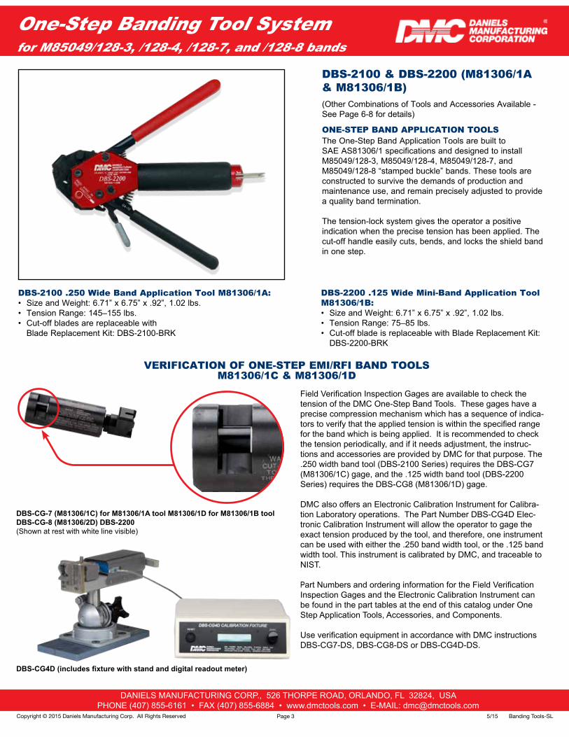
Field Verification Inspection Gages are available to check the tension of the DMC One-Step Band Tools. These gages have a precise compression mechanism which has a sequence of indica-tors to verify that the applied tension is within the specified range for the band which is being applied. It is recommended to check the tension periodically, and if it needs adjustment, the instruc-tions and accessories are provided by DMC for that purpose. The .250 width band tool (DBS-2100 Series) requires the DBS-CG7 (M81306/1C) gage, and the .125 width band tool (DBS-2200 Series) requires the DBS-CG8 (M81306/1D) gage.
DMC also offers an Electronic Calibration Instrument for Calibra-tion Laboratory operations. The Part Number DBS-CG4D Elec-tronic Calibration Instrument will allow the operator to gage the exact tension produced by the tool, and therefore, one instrument can be used with either the .250 band width tool, or the .125 band width tool. This instrument is calibrated by DMC, and traceable to NIST.
Part Numbers and ordering information for the Field Verification Inspection Gages and the Electronic Calibration Instrument can be found in the part tables at the end of this catalog under One Step Application Tools, Accessories, and Components.
Use verification equipment in accordance with DMC instructions DBS-CG7-DS, DBS-CG8-DS or DBS-CG4D-DS.
One-Step Banding Tool System for M85049/128-3, /128-4, /128-7, and /128-8 bands
DBS-2100 & DBS-2200 (M81306/1A & M81306/1B) (Other Combinations of Tools and Accessories Available - See Page 6-8 for details)
ONE-STEP BAND APPLICATION TOOLSThe One-Step Band Application Tools are built to SAE AS81306/1 specifications and designed to install M85049/128-3, M85049/128-4, M85049/128-7, and M85049/128-8 “stamped buckle” bands. These tools are constructed to survive the demands of production and maintenance use, and remain precisely adjusted to provide a quality band termination.
The tension-lock system gives the operator a positive indication when the precise tension has been applied. The cut-off handle easily cuts, bends, and locks the shield band in one step.
VERIFICATION OF ONE-STEP EMI/RFI BAND TOOLS M81306/1C & M81306/1D
DBS-CG4D (includes fixture with stand and digital readout meter)
DBS-CG-7 (M81306/1C) for M81306/1A tool M81306/1D for M81306/1B toolDBS-CG-8 (M81306/2D) DBS-2200(Shown at rest with white line visible)
DBS-2200 .125 Wide Mini-Band Application Tool M81306/1B:• Size and Weight: 6.71” x 6.75” x .92”, 1.02 lbs.• Tension Range: 75–85 lbs.• Cut-off blade is replaceable with Blade Replacement Kit:
DBS-2200-BRK
DBS-2100 .250 Wide Band Application Tool M81306/1A:• Size and Weight: 6.71” x 6.75” x .92”, 1.02 lbs.• Tension Range: 145–155 lbs.• Cut-off blades are replaceable with
Blade Replacement Kit: DBS-2100-BRK
Page 3
DANIELS MANUFACTURING CORP., 526 THORPE ROAD, ORLANDO, FL 32824, USAPHONE (407) 855-6161 • FAX (407) 855-6884 • www.dmctools.com • E-MAIL: [email protected]
5/15 Banding Tools-SL Copyright © 2015 Daniels Manufacturing Corp. All Rights Reserved
One-Step Procedures for M85049/128-3, /128-4, /128-7, and /128-8 bands
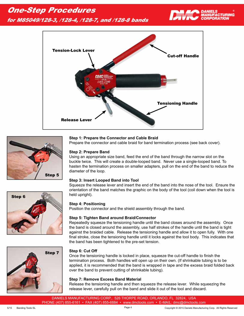
Step 1: Prepare the Connector and Cable BraidPrepare the connector and cable braid for band termination process (see back cover).
Step 2: Prepare BandUsing an appropriate size band, feed the end of the band through the narrow slot on the buckle twice. This will create a double-looped band. Never use a single-looped band. To hasten the termination process on smaller adapters, pull on the end of the band to reduce the diameter of the loop.
Step 3: Insert Looped Band into ToolSqueeze the release lever and insert the end of the band into the nose of the tool. Ensure the orientation of the band matches the graphic on the body of the tool (coil down when the tool is held upright).
Step 4: PositioningPosition the connector and the shield assembly through the band.
Step 5: Tighten Band around Braid/ConnectorRepeatedly squeeze the tensioning handle until the band closes around the assembly. Once the band is closed around the assembly, use half strokes of the handle until the band is tight against the braided cable. Release the tensioning handle and allow it to open fully. With one final stroke, close the tensioning handle until it locks against the tool body. This indicates that the band has been tightened to the pre-set tension.
Step 6: Cut Off Once the tensioning handle is locked in place, squeeze the cut-off handle to finish the termination process. Both handles will open up on their own. (If shrinkable tubing is to be applied, it is recommended that the band is wrapped in tape and the excess braid folded back over the band to prevent cutting of shrinkable tubing).
Step 7: Remove Excess Band MaterialRelease the tensioning handle and then squeeze the release lever. While squeezing the release lever, carefully pull on the band and slide it out of the tool and discard.
Step 5
Step 6
Step 7
Page 4
Release Lever
Tensioning Handle
Tension-Lock LeverCut-off Handle
DANIELS MANUFACTURING CORP., 526 THORPE ROAD, ORLANDO, FL 32824, USAPHONE (407) 855-6161 • FAX (407) 855-6884 • www.dmctools.com • E-MAIL: [email protected]
5/15 Banding Tools-SLCopyright © 2015 Daniels Manufacturing Corp. All Rights Reserved
Two-Step Banding Tools System for M85049/128-1, /128-2, /128-5, and /128-6 bands
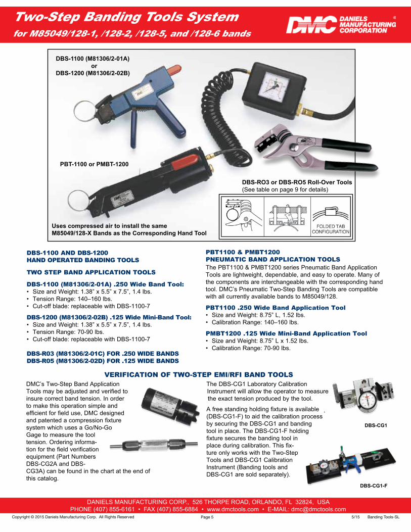
PBT1100 & PMBT1200 PNEUMATIC BAND APPLICATION TOOLSThe PBT1100 & PMBT1200 series Pneumatic Band Application Tools are lightweight, dependable, and easy to operate. Many of the components are interchangeable with the corresponding hand tool. DMC’s Pneumatic Two-Step Banding Tools are compatible with all currently available bands to M85049/128.
PBT1100 .250 Wide Band Application Tool• Size and Weight: 8.75” L, 1.52 lbs.• Calibration Range: 140–160 lbs.
PMBT1200 .125 Wide Mini-Band Application Tool• Size and Weight: 8.75” L x 1.52 lbs.• Calibration Range: 70-90 lbs.
DBS-1100 AND DBS-1200 HAND OPERATED BANDING TOOLS
TWO STEP BAND APPLICATION TOOLS
DBS-1100 (M81306/2-01A) .250 Wide Band Tool:• Size and Weight: 1.38” x 5.5” x 7.5”, 1.4 lbs.• Tension Range: 140–160 lbs.• Cut-off blade: replaceable with DBS-1100-7
DBS-1200 (M81306/2-02B) .125 Wide Mini-Band Tool:• Size and Weight: 1.38” x 5.5” x 7.5”, 1.4 lbs.• Tension Range: 70-90 lbs.• Cut-off blade: replaceable with DBS-1100-7
DBS-R03 (M81306/2-01C) FOR .250 WIDE BANDS DBS-R05 (M81306/2-02D) FOR .125 WIDE BANDS
The DBS-CG1 Laboratory Calibration Instrument will allow the operator to measure the exact tension produced by the tool.
A free standing holding fixture is available (DBS-CG1-F) to aid the calibration process by securing the DBS-CG1 and banding tool in place. The DBS-CG1-F holding fixture secures the banding tool in place during calibration. This fix-ture only works with the Two-Step Tools and DBS-CG1 Calibration Instrument (Banding tools and DBS-CG1 are sold separately).
DMC’s Two-Step Band Application Tools may be adjusted and verified to insure correct band tension. In order to make this operation simple and efficient for field use, DMC designed and patented a compression fixture system which uses a Go/No-Go Gage to measure the tool tension. Ordering informa-tion for the field verification equipment (Part Numbers DBS-CG2A and DBS-CG3A) can be found in the chart at the end of this catalog.
DBS-1100 (M81306/2-01A)or
DBS-1200 (M81306/2-02B)
PBT-1100 or PMBT-1200
DBS-RO3 or DBS-RO5 Roll-Over Tools(See table on page 9 for details)
DBS-CG1
Uses compressed air to install the same M85049/128-X Bands as the Corresponding Hand Tool
VERIFICATION OF TWO-STEP EMI/RFI BAND TOOLS
DBS-CG1-F
Page 5
DANIELS MANUFACTURING CORP., 526 THORPE ROAD, ORLANDO, FL 32824, USAPHONE (407) 855-6161 • FAX (407) 855-6884 • www.dmctools.com • E-MAIL: [email protected]
5/15 Banding Tools-SL Copyright © 2015 Daniels Manufacturing Corp. All Rights Reserved
Two-Step Procedures for M85049/128-1, /128-2, /128-5, and /128-6 bands
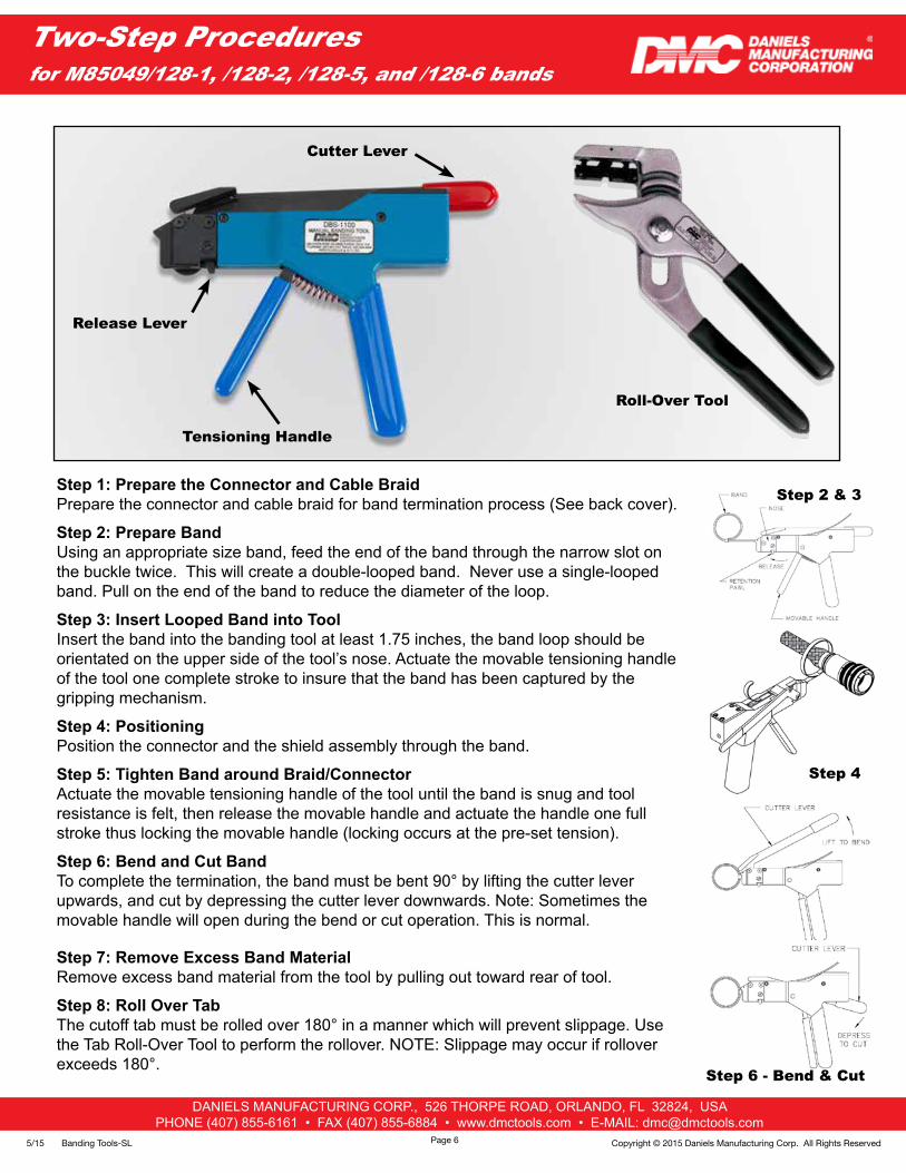
Step 1: Prepare the Connector and Cable BraidPrepare the connector and cable braid for band termination process (See back cover).
Step 2: Prepare BandUsing an appropriate size band, feed the end of the band through the narrow slot on the buckle twice. This will create a double-looped band. Never use a single-looped band. Pull on the end of the band to reduce the diameter of the loop.
Step 3: Insert Looped Band into ToolInsert the band into the banding tool at least 1.75 inches, the band loop should be orientated on the upper side of the tool’s nose. Actuate the movable tensioning handle of the tool one complete stroke to insure that the band has been captured by the gripping mechanism.
Step 4: PositioningPosition the connector and the shield assembly through the band.
Step 5: Tighten Band around Braid/ConnectorActuate the movable tensioning handle of the tool until the band is snug and tool resistance is felt, then release the movable handle and actuate the handle one full stroke thus locking the movable handle (locking occurs at the pre-set tension).
Step 6: Bend and Cut BandTo complete the termination, the band must be bent 90° by lifting the cutter lever upwards, and cut by depressing the cutter lever downwards. Note: Sometimes the movable handle will open during the bend or cut operation. This is normal.
Step 7: Remove Excess Band MaterialRemove excess band material from the tool by pulling out toward rear of tool.
Step 8: Roll Over TabThe cutoff tab must be rolled over 180° in a manner which will prevent slippage. Use the Tab Roll-Over Tool to perform the rollover. NOTE: Slippage may occur if rollover exceeds 180°.
Cutter Lever
Roll-Over Tool
Step 2 & 3
Step 4
Step 6 - Bend & Cut
Tensioning Handle
Release Lever
Page 6
DANIELS MANUFACTURING CORP., 526 THORPE ROAD, ORLANDO, FL 32824, USAPHONE (407) 855-6161 • FAX (407) 855-6884 • www.dmctools.com • E-MAIL: [email protected]
5/15 Banding Tools-SLCopyright © 2015 Daniels Manufacturing Corp. All Rights Reserved
M85049/128 Band Application SystemMIL Part Numbers
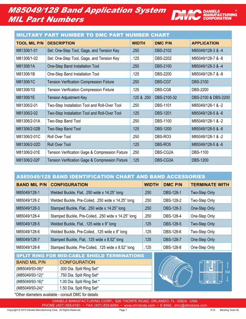
MILITARY PART NUMBER TO DMC PART NUMBER CHARTTOOL MIL P/N DESCRIPTION WIDTH DMC P/N APPLICATION
M81306/1-01 Set: One-Step Tool, Gage, and Tension Key .250 DBS-2102 M85049/128-3 & -4
M81306/1-02 Set: One-Step Tool, Gage, and Tension Key .125 DBS-2202 M85049/128-7 & -8
M81306/1A One-Step Band Installation Tool .250 DBS-2100 M85049/128-3 & -4
M81306/1B One-Step Band Installation Tool .125 DBS-2200 M85049/128-7 & -8
M81306/1C Tension Verification Compression Fixture .250 DBS-CG7 DBS-2100
M81306/1D Tension Verification Compression Fixture .125 DBS-CG8 DBS-2200
M81306/1E Tension Adjustment Key .125 & .250 DBS-2100-32 DBS-2100 & DBS-2200
M81306/2-01 Two-Step Installation Tool and Roll-Over Tool .250 DBS-1101 M85049/128-1 & -2
M81306/2-02 Two-Step Installation Tool and Roll-Over Tool .125 DBS-1201 M85049/128-5 & -6
M81306/2-01A Two-Step Band Tool .250 DBS-1100 M85049/128-1 & -2
M81306/2-02B Two-Step Band Tool .125 DBS-1200 M85049/128-5 & -6
M81306/2-01C Roll Over Tool .250 DBS-RO3 M85049/128-1 & -2
M81306/2-02D Roll Over Tool .125 DBS-RO5 M85049/128-5 & -6
M81306/2-01E Tension Verification Gage & Compression Fixture .250 DBS-CG2A DBS-1100
M81306/2-02F Tension Verification Gage & Compression Fixture .125 DBS-CG3A DBS-1200
AS85049/128 BAND IDENTIFICATION CHART AND BAND ACCESSORIESBAND MIL P/N CONFIGURATION WIDTH DMC P/N TERMINATE WITH
M85049/128-1 Welded Buckle, Flat, .250 wide x 14.25” long .250 DBS-128-1 Two-Step Only
M85049/128-2 Welded Buckle, Pre-Coiled, .250 wide x 14.25” long .250 DBS-128-2 Two-Step Only
M85049/128-3 Stamped Buckle, Flat, .250 wide x 14.25” long .250 DBS-128-3 One-Step Only
M85049/128-4 Stamped Buckle, Pre-Coiled, .250 wide x 14.25” long .250 DBS-128-4 One-Step Only
M85049/128-5 Welded Buckle, Flat, .125 wide x 9” long .125 DBS-128-5 Two-Step Only
M85049/128-6 Welded Buckle, Pre-Coiled, .125 wide x 9” long .125 DBS-128-6 Two-Step Only
M85049/128-7 Stamped Buckle, Flat, .125 wide x 8.52” long .125 DBS-128-7 One-Step Only
M85049/128-8 Stamped Buckle, Pre-Coiled, .125 wide x 8.52” long .125 DBS-128-8 One-Step Only
SPLIT RING FOR MID-CABLE SHIELD TERMINATIONSBAND MIL P/N CONFGURATION(M85049/93-08)* .500 Dia. Split Ring Set*(M85049/93-12)* .750 Dia. Split Ring Set*(M85049/93-16)* 1.00 Dia. Split Ring Set *(M85049/93-24)* 1.50 Dia. Split Ring Set*
*Other diameters available - consult DMC for details
DIA
Page 7
DANIELS MANUFACTURING CORP., 526 THORPE ROAD, ORLANDO, FL 32824, USAPHONE (407) 855-6161 • FAX (407) 855-6884 • www.dmctools.com • E-MAIL: [email protected]
5/15 Banding Tools-SL Copyright © 2015 Daniels Manufacturing Corp. All Rights Reserved
M85049/128 Band Application SystemDMC Part Numbers
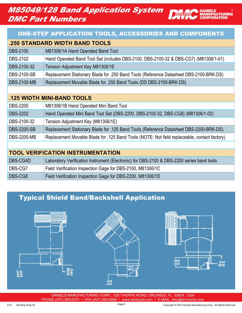
ONE-STEP APPLICATION TOOLS, ACCESSORIES AND COMPONENTS.250 STANDARD WIDTH BAND TOOLSDBS-2100 M81306/1A Hand Operated Band ToolDBS-2102 Hand Operated Band Tool Set (includes DBS-2100, DBS-2100-32 & DBS-CG7) (M81306/1-01)DBS-2100-32 Tension Adjustment Key M81306/1EDBS-2100-SB Replacement Stationary Blade for .250 Band Tools (Reference Datasheet DBS-2100-BRK-DS)DBS-2100-MB Replacement Movable Blade for .250 Band Tools (DS DBS-2100-BRK-DS)
.125 WIDTH MINI-BAND TOOLSDBS-2200 M81306/1B Hand Operated Mini Band Tool DBS-2202 Hand Operated Mini Band Tool Set (DBS-2200, DBS-2100-32, DBS-CG8) (M81306/1-02)DBS-2100-32 Tension Adjustment Key (M81306/1E)DBS-2200-SB Replacement Stationary Blade for .125 Band Tools (Reference Datasheet DBS-2200-BRK-DS)DBS-2200-MB Replacement Movable Blade for .125 Band Tools (NOTE: Not field replaceable, contact factory)
TOOL VERIFICATION INSTRUMENTATIONDBS-CG4D Laboratory Verification Instrument (Electronic) for DBS-2100 & DBS-2200 series band tools DBS-CG7 Field Verification Inspection Gage for DBS-2100, M81306/1CDBS-CG8 Field Verification Inspection Gage for DBS-2200, M81306/1D
Page 8
Typical Shield Band/Backshell Application
DANIELS MANUFACTURING CORP., 526 THORPE ROAD, ORLANDO, FL 32824, USAPHONE (407) 855-6161 • FAX (407) 855-6884 • www.dmctools.com • E-MAIL: [email protected]
5/15 Banding Tools-SLCopyright © 2015 Daniels Manufacturing Corp. All Rights Reserved
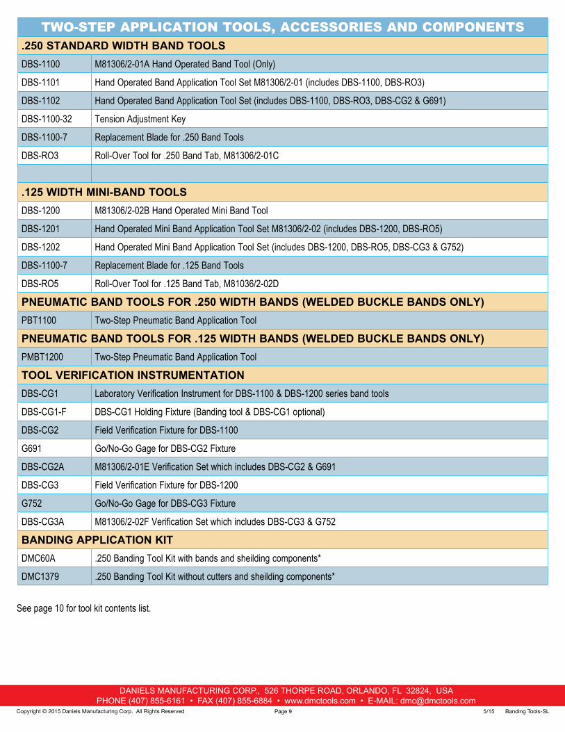
TWO-STEP APPLICATION TOOLS, ACCESSORIES AND COMPONENTS.250 STANDARD WIDTH BAND TOOLSDBS-1100 M81306/2-01A Hand Operated Band Tool (Only)
DBS-1101 Hand Operated Band Application Tool Set M81306/2-01 (includes DBS-1100, DBS-RO3)
DBS-1102 Hand Operated Band Application Tool Set (includes DBS-1100, DBS-RO3, DBS-CG2 & G691)
DBS-1100-32 Tension Adjustment Key
DBS-1100-7 Replacement Blade for .250 Band Tools
DBS-RO3 Roll-Over Tool for .250 Band Tab, M81306/2-01C
.125 WIDTH MINI-BAND TOOLSDBS-1200 M81306/2-02B Hand Operated Mini Band Tool
DBS-1201 Hand Operated Mini Band Application Tool Set M81306/2-02 (includes DBS-1200, DBS-RO5)
DBS-1202 Hand Operated Mini Band Application Tool Set (includes DBS-1200, DBS-RO5, DBS-CG3 & G752)
DBS-1100-7 Replacement Blade for .125 Band Tools
DBS-RO5 Roll-Over Tool for .125 Band Tab, M81036/2-02D
PNEUMATIC BAND TOOLS FOR .250 WIDTH BANDS (WELDED BUCKLE BANDS ONLY)PBT1100 Two-Step Pneumatic Band Application Tool
PNEUMATIC BAND TOOLS FOR .125 WIDTH BANDS (WELDED BUCKLE BANDS ONLY)PMBT1200 Two-Step Pneumatic Band Application Tool
TOOL VERIFICATION INSTRUMENTATIONDBS-CG1 Laboratory Verification Instrument for DBS-1100 & DBS-1200 series band tools
DBS-CG1-F DBS-CG1 Holding Fixture (Banding tool & DBS-CG1 optional)
DBS-CG2 Field Verification Fixture for DBS-1100
G691 Go/No-Go Gage for DBS-CG2 Fixture
DBS-CG2A M81306/2-01E Verification Set which includes DBS-CG2 & G691
DBS-CG3 Field Verification Fixture for DBS-1200
G752 Go/No-Go Gage for DBS-CG3 Fixture
DBS-CG3A M81306/2-02F Verification Set which includes DBS-CG3 & G752
BANDING APPLICATION KITDMC60A .250 Banding Tool Kit with bands and sheilding components*
DMC1379 .250 Banding Tool Kit without cutters and sheilding components*
See page 10 for tool kit contents list.
Page 9
DANIELS MANUFACTURING CORP., 526 THORPE ROAD, ORLANDO, FL 32824, USAPHONE (407) 855-6161 • FAX (407) 855-6884 • www.dmctools.com • E-MAIL: [email protected]
5/15 Banding Tools-SL Copyright © 2015 Daniels Manufacturing Corp. All Rights Reserved
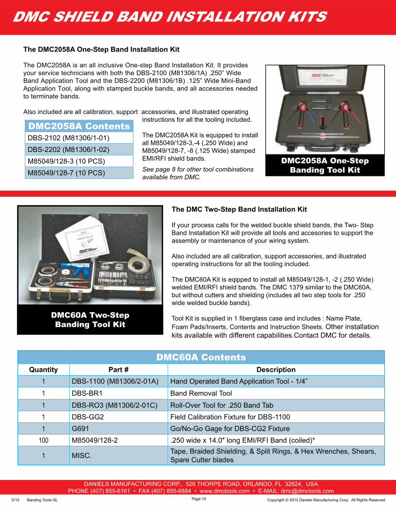
The DMC2058A One-Step Band Installation Kit
The DMC2058A is an all inclusive One-step Band Installation Kit. It provides your service technicians with both the DBS-2100 (M81306/1A) .250” Wide Band Application Tool and the DBS-2200 (M81306/1B) .125” Wide Mini-Band Application Tool, along with stamped buckle bands, and all accessories needed to terminate bands.
Also included are all calibration, support accessories, and illustrated operating instructions for all the tooling included.
The DMC2058A Kit is equipped to install all M85049/128-3,-4 (.250 Wide) and M85049/128-7, -8 (.125 Wide) stamped EMI/RFI shield bands.
See page 8 for other tool combinations available from DMC.
DMC SHIELD BAND INSTALLATION KITS
DMC60A Two-Step Banding Tool Kit
The DMC Two-Step Band Installation Kit
If your process calls for the welded buckle shield bands, the Two- Step Band Installation Kit will provide all tools and accesories to support the assembly or maintenance of your wiring system.
Also included are all calibration, support accessories, and illustrated operating instructions for all the tooling included.
The DMC60A Kit is eqipped to install all M85049/128-1, -2 (.250 Wide) welded EMI/RFI shield bands. The DMC 1379 similar to the DMC60A, but without cutters and shielding (includes all two step tools for .250 wide welded buckle bands).
Tool Kit is supplied in 1 fiberglass case and includes : Name Plate, Foam Pads/Inserts, Contents and Instruction Sheets. Other installation kits available with different capabilities.Contact DMC for details.
DMC2058A One-Step Banding Tool Kit
DMC60A ContentsQuantity Part # Description
1 DBS-1100 (M81306/2-01A) Hand Operated Band Application Tool - 1/4”
1 DBS-BR1 Band Removal Tool
1 DBS-RO3 (M81306/2-01C) Roll-Over Tool for .250 Band Tab1 DBS-GG2 Field Calibration Fixture for DBS-11001 G691 Go/No-Go Gage for DBS-CG2 Fixture
100 M85049/128-2 .250 wide x 14.0″ long EMI/RFI Band (coiled)*
1 MISC. Tape, Braided Shielding, & Split Rings, & Hex Wrenches, Shears, Spare Cutter blades
DMC2058A ContentsDBS-2102 (M81306/1-01)DBS-2202 (M81306/1-02)M85049/128-3 (10 PCS)M85049/128-7 (10 PCS)
Page 10
Copyright © 2015 Daniels Manufacturing Corp. All Rights Reserved
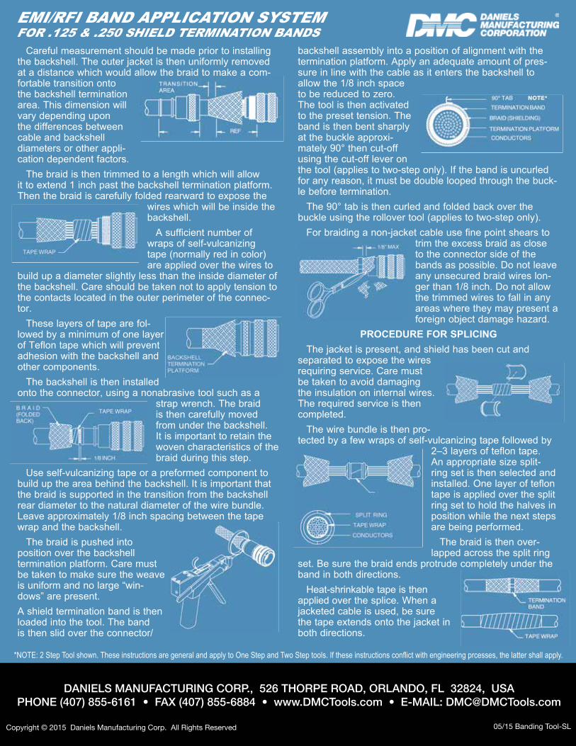
EMI/RFI BAND APPLICATION SYSTEMFOR .125 & .250 SHIELD TERMINATION BANDS
Careful measurement should be made prior to installing the backshell. The outer jacket is then uniformly removed at a distance which would allow the braid to make a com-fortable transition onto the backshell termination area. This dimension will vary depending upon the differences between cable and backshell diameters or other appli-cation dependent factors.
The braid is then trimmed to a length which will allow it to extend 1 inch past the backshell termination platform. Then the braid is carefully folded rearward to expose the
wires which will be inside the backshell.
A sufficient number of wraps of self-vulcanizing tape (normally red in color) are applied over the wires to
build up a diameter slightly less than the inside diameter of the backshell. Care should be taken not to apply tension to the contacts located in the outer perimeter of the connec-tor.
These layers of tape are fol-lowed by a minimum of one layer of Teflon tape which will prevent adhesion with the backshell and other components.
The backshell is then installed onto the connector, using a nonabrasive tool such as a
strap wrench. The braid is then carefully moved from under the backshell. It is important to retain the woven characteristics of the braid during this step.
Use self-vulcanizing tape or a preformed component to build up the area behind the backshell. It is important that the braid is sup ported in the transition from the backshell rear diameter to the natural diameter of the wire bundle. Leave approximately 1/8 inch spacing between the tape wrap and the backshell.
The braid is pushed into position over the backshell termination platform. Care must be taken to make sure the weave is uniform and no large “win-dows” are present. A shield termination band is then loaded into the tool. The band is then slid over the connector/
backshell assembly into a position of alignment with the ter mination platform. Apply an adequate amount of pres-sure in line with the cable as it enters the backshell to allow the 1/8 inch space to be reduced to zero. The tool is then activated to the preset tension. The band is then bent sharply at the buckle approxi-mately 90° then cut-off using the cut-off lever on the tool (applies to two-step only). If the band is uncurled for any reason, it must be double looped through the buck-le before termination.
The 90° tab is then curled and folded back over the buckle using the rollover tool (applies to two-step only).
For braiding a non-jacket cable use fine point shears to trim the excess braid as close to the connector side of the bands as possible. Do not leave any unsecured braid wires lon-ger than 1/8 inch. Do not allow the trimmed wires to fall in any areas where they may present a foreign object damage hazard.
PROCEDURE FOR SPLICINGThe jacket is present, and shield has been cut and
separated to expose the wires requiring service. Care must be taken to avoid damaging the insulation on internal wires. The required service is then completed.
The wire bundle is then pro-tected by a few wraps of self-vulcanizing tape followed by
2–3 layers of teflon tape. An appro priate size split-ring set is then selected and installed. One layer of teflon tape is applied over the split ring set to hold the halves in position while the next steps are being performed.
The braid is then over-lapped across the split ring
set. Be sure the braid ends protrude completely under the band in both directions.
Heat-shrinkable tape is then applied over the splice. When a jacketed cable is used, be sure the tape extends onto the jacket in both directions.
DANIELS MANUFACTURING CORP., 526 THORPE ROAD, ORLANDO, FL 32824, USAPHONE (407) 855-6161 • FAX (407) 855-6884 • www.DMCTools.com • E-MAIL: [email protected]
05/15 Banding Tool-SL
*NOTE: 2 Step Tool shown. These instructions are general and apply to One Step and Two Step tools. If these instructions conflict with engineering prcesses, the latter shall apply.