EMI Grounding Chap 5
30
81 Chapter 5 Grounding for the Control of EMI There are two primary reasons for grounding devices, cables, equip- ments, and systems. The first reason is to prevent shock and fire haz- ards in the event that an equipment frame or housing develops a high voltage due to lightning or an accidental breakdown of wiring or compo- nents. The second reason is to reduce EMI effects resulting from elec- tromagnetic fields, common impedance, or other forms of interference coupling. Historically, grounding requirements arose from the need to provide protection from electrical faults, lightning, and industrially generated static electricity. Because most power-fault and lightning control relies on a low-impedance path to earth, all major components of an electrical power generation and transmission system were earth grounded to pro- vide the required low-impedance path. As a result, strong emphasis was placed on earth grounding of electrical equipment, and the overall phi- losophy was “ground, ground, ground” without regard to other prob- lems, such as EMI, that may be created by this approach. When electronic equipments were introduced, grounding problems became evident. These problems resulted from the fact that the circuit and equipment grounds often provided the mechanism for undesired EMI coupling. Also, with electronic systems, the ground may simulta- neously perform two or more functions, and these multiple functions may be in conflict either in terms of operational requirements or in terms of implementation techniques. For example, as illustrated in Fig. 5.1, the ground network for an electronic equipment may be used as a signal return, provide safety, provide EMI control, and also per- form as part of an antenna system. Therefore, in order to avoid creating EMI problems, it is essential to recognize that an effective grounding system, like any other portion of
Transcript of EMI Grounding Chap 5

81
Chapter 5
Grounding for the Control of EMI
There are two primary reasons for grounding devices, cables, equip-ments, and systems. The first reason is to prevent shock and fire haz-ards in the event that an equipment frame or housing develops a highvoltage due to lightning or an accidental breakdown of wiring or compo-nents. The second reason is to reduce EMI effects resulting from elec-tromagnetic fields, common impedance, or other forms of interferencecoupling.
Historically, grounding requirements arose from the need to provideprotection from electrical faults, lightning, and industrially generatedstatic electricity. Because most power-fault and lightning control relieson a low-impedance path to earth, all major components of an electricalpower generation and transmission system were earth grounded to pro-vide the required low-impedance path. As a result, strong emphasis wasplaced on earth grounding of electrical equipment, and the overall phi-losophy was “ground, ground, ground” without regard to other prob-lems, such as EMI, that may be created by this approach.
When electronic equipments were introduced, grounding problemsbecame evident. These problems resulted from the fact that the circuitand equipment grounds often provided the mechanism for undesiredEMI coupling. Also, with electronic systems, the ground may simulta-neously perform two or more functions, and these multiple functionsmay be in conflict either in terms of operational requirements or interms of implementation techniques. For example, as illustrated inFig. 5.1, the ground network for an electronic equipment may be usedas a signal return, provide safety, provide EMI control, and also per-form as part of an antenna system.
Therefore, in order to avoid creating EMI problems, it is essential torecognize that an effective grounding system, like any other portion of
Duff.book Page 81 Friday, January 28, 2011 2:18 PM
82 GROUNDING FOR THE CONTROL OF EMI
an equipment or system, must be carefully designed and implemented.Grounding is a system problem and in order for a grounding arrange-ment to perform well it must be well conceived and accurately designedand implemented. The grounding configurations must be weighed withregard to dimensions and frequency, just like any functional circuit.
The objective of this chapter is to help engineers, designers, andtechnicians to optimize the functionality and reliability of their equip-ment by providing an orderly systems approach to grounding. Such anapproach is highly preferable to the empirical and sometimes contradic-tory approaches that are often employed.
5.1 Definitions
The term ground is one of the most abused words in the electronic engi-neering vocabulary. In addition, several other words are often used inconjunction with the term ground, and these words are also often mis-used. For the purpose of this chapter, it is important to carefully definethese terms. The definitions that follow are given in terms of the nounrather than the verb.
Ground: Any reference conductor that is used for a common return.
Earth: The soil into which a safety conductor (rod, grid, plate) is driven or buried to provide a low-impedance sink for fault and lightning cur-rents.
Electronic Enclosure
Sig.In Sig.
OutSignal Ground, Signal Return, dc Common
Signal Ground, Cabinet Ground, Safety Ground, etc.
Building Ground, Power Ground, Safety Ground, etc.
Antenna Ground,Building Ground,Lightning Groundetc.
Figure 5.1 The multiple functions of grounds.
Duff.book Page 82 Friday, January 28, 2011 2:18 PM

CHARACTERISTICS OF GROUNDING SYSTEMS 83
Reference: Some object whose potential (often 0 V with respect to earth or a power supply) is the one to which analog and logic circuits, equipments, and systems can be related or benchmarked.
Return: The low (reference) voltage side of a wire pair (e.g., neutral), outer jacket of a coax or conductor providing a path for intentional current to get back to the source.
Bond: The process used to join two metal surfaces via a low-impedance path.
Connection: A mechanical joint between two electrical conductors, often including an intermediary conductor such as a jumper, pigtail, or shield braid.
Figure 5.2 illustrates the reason that the term ground can be a mis-leading, ambiguous term if one does not consider its electrical parame-ters. Referring to Fig. 5.2, it is apparent that significant voltages mayexist between two different points on the “ground” associated with aplatform, facility, or rack. This potential difference is a major cause forEMI problems resulting from grounding of circuits, equipments, or sys-tems.
5.2 Characteristics of Grounding Systems
Ideally, a ground system should provide a zero-impedance path to allsignals for which it serves as a reference. If this were the situation, sig-nal currents from different circuits or equipments that are connected tothe ground could return to their respective sources without creatingunwanted coupling between the circuits or equipments. Many interfer-ence problems occur because designers treat the ground as ideal andfail to give proper attention to the actual characteristics of the ground-ing system. One of the primary reasons that designers treat the groundsystem as ideal is that this assumption is often valid from the stand-point of the circuit or equipment design parameters (i.e., the impedanceat power or signal frequencies is small and has little or no impact oncircuit or equipment performance). However, the non-ideal properties ofthe ground must be recognized if EMI problems are to be avoided.
5.2.1 Impedance Characteristics
Every element (conductor) of a grounding system, whether it be forpower grounding, signal grounding, or lightning protection, has proper-ties of resistance, capacitance, and inductance. Shields and drain wires
Duff.book Page 83 Friday, January 28, 2011 2:18 PM

84 GROUNDING FOR THE CONTROL OF EMI
of signal cables, the green wire power safety ground, lightning downconductors, transformer vault buses, structural steel members—allconductors have these properties. The resistance property is exhibitedby all metals. The resistance of a ground path conductor is a function ofthe material, its length, and its cross-sectional area. The capacitanceassociated with a ground conductor is determined by its geometric
“Ground” Means any Reference Conductorthat is Used for a Common Return
Earthing is only a particular case of grounding.
Ground?
100 V 50 V
On an aircraft, 10 to 100 Vdifferences may existbetween structural points.
In a building, levels of severalkilovolts develop on groundswhen lightning creates earthgradients.
In a ship, levels of severalhundred volts existbetween decks,superstructures and rigging.
In vehicles, differences ofseveral volts develop betweenpoints on the steel body.
In racks, several hundredmillivolts can develop betweendifferent drawers.
What For?Where?How?
Is this “ground”really equipotential?
0 VRef.
30 V
17 V
10 V
10 V
10 V
80 V
Figure 5.2 Ground can be a misleading, ambiguous term if one does not con-sider its electrical parameters.
Duff.book Page 84 Friday, January 28, 2011 2:18 PM

CHARACTERISTICS OF GROUNDING SYSTEMS 85
shape, its proximity to other conductors, and the nature of the interven-ing dielectric. The inductance is a function of its size, geometry, length,and, to a limited extent, the relative permeability of the metal. Theimpedance of the grounding system is a function of the resistance,inductance, capacitance, and frequency.
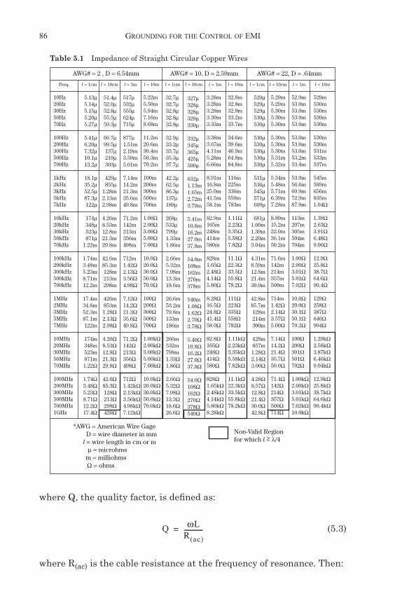
Because the inductance properties of a conductor decrease withwidth and increase with length, it is frequently recommended that alength-to-width ratio of 5:1 be used for grounding straps. This 5:1length-to-width ratio provides a reactance that is approximately 45 per-cent of that of a straight circular wire.
The impedance of straight circular wires is provided as a function offrequency in Table 5.1 for several wire gauges and lengths. Typicalground plane impedances are provided in Table 5.2 for comparison. Notethat for typical length wires, ground plane impedances are several ordersof magnitude less than those of a circular wire. Also note that the imped-ance of both circular wires and ground planes increase with increasingfrequency and become quite significant at higher frequencies.
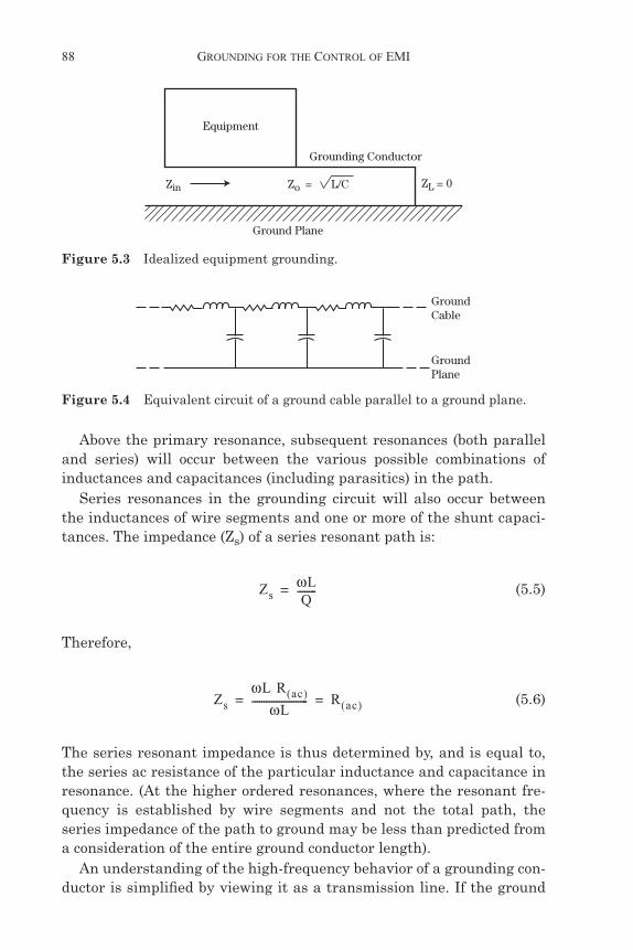
A commonly encountered situation is that of a ground cable (poweror signal) running along in the proximity of a ground plane. This situa-tion is illustrated in Fig. 5.3 for equipment grounding. Figure 5.4 illus-trates a representative circuit of this simple ground path. The effects ofthe resistive elements of the circuit will predominate at very low fre-quencies. The relative influence of the reactive elements will increaseat increasing frequencies. At some frequency, the magnitude of theinductive reactance (j!L) equals the magnitude of the capacitive reac-tance (1/j!C), and the circuit becomes resonant. The frequency of theprimary (or first) resonance can be determined from:
(5.1)
where L is the total cable inductance, and C is the net capacitancebetween the cable and the ground plane. At resonance, the impedancepresented by the grounding path will either be high or low, dependingon whether it is parallel or series resonant, respectively. At parallel res-onance, the impedance seen looking into one end of the cable will bemuch higher than expected from R + j!L. (For good conductors, e.g.,copper and aluminum, R « !L; thus, j!L generally provides an accurateestimate of the impedance of a ground conductor at frequencies above afew hundred hertz). At parallel resonance:
Zp = Q!L (5.2)
f 1
2" LC-------------------=
Duff.book Page 85 Friday, January 28, 2011 2:18 PM
86 GROUNDING FOR THE CONTROL OF EMI
where Q, the quality factor, is defined as:
(5.3)
where R(ac) is the cable resistance at the frequency of resonance. Then:
10Hz20Hz30Hz50Hz70Hz
100Hz200Hz300Hz500Hz700Hz
1kHz2kHz3kHz5kHz7kHz
10kHz20kHz30kHz50kHz70kHz
100kHz200kHz300kHz500kHz700kHz
1MHz2MHz3MHz5MHz7MHz
10MHz20MHz30MHz50MHz70MHz
100MHz200MHz300MHz500MHz700MHz1GHz
5.13µ5.14µ5.15µ5.20µ5.27µ
5.41µ6.20µ7.32µ10.1µ13.2µ
18.1µ35.2µ52.5µ87.3µ122µ
174µ348µ523µ871µ
1.22m
1.74m3.48m5.23m8.71m12.2m
17.4m34.8m52.3m87.1m122m
174m348m523m871m1.22!
1.74!3.48!5.23!8.71!12.2!17.4!
51.4µ52.0µ52.8µ55.5µ59.3µ
66.7µ99.5µ137µ219µ303µ
429µ855µ
1.28m2.13m2.98m
4.26m8.53m12.8m21.3m29.8m
42.6m85.3m128m213m298m
426m853m1.28!2.13!2.98!
4.26!8.53!12.8!21.3!29.8!
42.6!85.3!128!213!298!426!
517µ532µ555µ624µ715µ
877µ1.51m2.19m3.59m5.01m
7.14m14.2m21.3m35.6m49.8m
71.2m142m213m356m498m
712m1.42!2.13!3.56!4.98!
7.12!14.2!21.3!35.6!49.8!
71.2!142!213!356!498!
712!1.42k!2.13k!3.56k!4.98k!7.12k!
5.22m5.50m5.94m7.16m8.68m
11.2m20.6m30.4m50.3m70.2m
100m200m300m500m700m
1.00!2.00!3.00!5.00!7.00!
10.0!20.0!30.0!50.0!70.0!
100!200!300!500!700!
1.00k!2.00k!3.00k!5.00k!7.00k!
10.0k!20.0k!30.0k!50.0k!70.0k!
32.7µ32.7µ32.8µ32.8µ32.8µ
32.9µ33.2µ33.7µ35.3µ37.7µ
42.2µ62.5µ86.3µ137µ189µ
268µ533µ799µ1.33m1.86m
2.66m5.32m7.98m13.3m18.6m
26.6m53.2m79.8m133m186m
266m532m798m1.33!1.86!
2.66!5.32!7.98!13.3!18.6!26.6!
327µ328µ328µ329µ330µ
332µ345µ365µ425µ500µ
632µ1.13m1.65m2.72m3.79m
5.41m10.8m16.2m27.0m37.8m
54.0m108m162m270m378m
540m1.08!1.62!2.70!3.78!
5.40!10.8!16.2!27.0!37.8!
54.0!108!162!270!378!540!
3.28m3.28m3.28m3.30m3.33m
3.38m3.67m4.11m5.28m6.66m
8.91m16.8m25.0m41.5m58.1m
82.9m165m248m414m580m
828m1.65!2.48!4.14!5.80!
8.28!16.5!24.8!41.4!58.0!
82.8!165!248!414!580!
828!1.65k!2.48k!4.14k!5.80k!8.28k!
32.8m32.8m32.9m33.2m33.7m
34.6m39.6m46.9m64.8m84.8m
116m225m336m559m783m
1.11!2.23!3.35!5.58!7.82!
11.1!22.3!33.5!55.8!78.2!
111!223!335!558!782!
1.11k!2.23k!3.35k!5.58k!7.82k!
11.1k!22.3k!33.5k!55.8k!78.2k!
529µ529µ529µ530µ530µ
530µ530µ530µ530µ530µ
531µ536µ545µ571µ609µ
681µ1.00m1.39m2.20m3.04m
4.31m8.59m12.8m21.4m30.0m
42.8m85.7m128m214m300m
428m857m1.28!2.14!3.00!
4.28!8.57!12.8!21.4!30.0!42.8!
5.29m5.29m5.30m5.30m5.30m
5.30m5.30m5.30m5.31m5.32m
5.34m5.48m5.71m6.39m7.28m
8.89m15.2m22.0m36.1m50.2m
71.6m142m214m357m500m
714m1.42!2.14!3.57!5.00!
7.14!14.2!21.4!35.7!50.0!
71.4!142!214!357!500!714!
52.9m53.0m53.0m53.0m53.0m
53.0m53.0m53.0m53.2m53.4m
53.9m56.6m60.9m72.9m87.9m
113m207m305m504m704m
1.00!2.00!3.01!5.01!7.02!
10.0!20.0!30.1!50.1!70.2!
100!200!301!501!702!
1.00k!2.00k!3.01k!5.01k!7.02k!10.0k!
529m530m530m530m530m
530m530m531m533m537m
545m589m656m835m1.04!
1.39!2.63!3.91!6.48!9.06!
12.9!25.8!38.7!64.6!90.4!
129!258!387!646!904!
1.29k!2.58k!3.87k!6.46k!9.04k!
12.9k!25.8k!38.7k!64.6k!90.4k!
AWG# = 2 , D = 6.54mm AWG# = 10, D = 2.59mm AWG# = 22, D = .64mm
Freq. l = 1cm l = 10cm l = 1m l = 10m l = 1cm l = 10cm l = 1m l = 10m l = 1cm l = 10cm l = 1m l = 10m
*AWG = American Wire Gage D = wire diameter in mm l = wire length in cm or m µ = microhms m = milliohms ! = ohms
Non-Valid Regionfor which l " #/4
Table 5.1 Impedance of Straight Circular Copper Wires
Q !LR ac( )------------=
Duff.book Page 86 Friday, January 28, 2011 2:18 PM

CHARACTERISTICS OF GROUNDING SYSTEMS 87
(5.4)
10Hz20Hz30Hz50Hz70Hz
100Hz200Hz300Hz500Hz700Hz
1kHz2kHz3kHz5kHz7kHz
10kHz20kHz30kHz50kHz70kHz
100kHz200kHz300kHz500kHz700kHz
1MHz2MHz3MHz5MHz7MHz
10MHz20MHz30MHz50MHz70MHz
100MHz200MHz300MHz500MHz700MHz
1GHz2GHz3GHz5GHz7GHz10GHz
574µ574µ574µ574µ574µ
574µ574µ574µ574µ574µ
574µ574µ574µ574µ574µ
574µ574µ574µ574µ574µ
574µ575µ575µ576µ578µ
582µ604µ638µ736µ855µ
1.04m1.61m2.03m2.62m3.09m
3.69m5.22m6.39m8.26m9.77m
11.6m16.5m20.2m26.1m30.9m36.9m
172µ172µ172µ172µ172µ
172µ172µ172µ172µ172µ
172µ172µ172µ172µ172µ
172µ172µ172µ173µ173µ
175µ183µ195µ230µ271µ
335µ516µ643µ827µ977µ
1.16m1.65m2.02m2.61m3.09m
3.69m5.22m6.39m8.26m9.77m
11.6m16.5m20.2m26.1m30.9m36.9m
57.4µ57.4µ57.4µ57.4µ57.4µ
57.4µ57.4µ57.4µ57.4µ57.4µ
57.4µ57.5µ57.5µ57.6µ57.8µ
58.2µ60.4µ63.8µ73.6µ85.5µ
140µ161µ203µ262µ309µ
369µ522µ639µ826µ977µ
1.16m1.65m2.02m2.61m3.09m
3.69m5.22m6.39m8.26m9.77m
11.6m16.5m20.2m26.1m30.9m36.9m
17.2µ17.2µ17.2µ17.2µ17.2µ
17.2µ17.2µ17.2µ17.3µ17.3µ
17.5µ18.3µ19.5µ23.0µ27.1µ
33.5µ51.6µ64.3µ82.7µ97.7µ
116µ165µ202µ261µ309µ
369µ522µ639µ826µ977µ
1.16m1.65m2.02m2.61m3.09m
3.69m5.22m6.39m8.26m9.77m
11.6m16.5m20.2m26.1m30.9m36.9m
5.74µ5.75µ5.75µ5.76µ5.78µ
5.82µ6.04µ6.38µ7.36µ8.55µ
10.4µ16.1µ20.3µ26.2µ30.9µ
36.9µ52.2µ63.9µ82.6µ97.7µ
116µ165µ202µ261µ309µ
369µ522µ639µ826µ977µ
1.16m1.65m2.02m2.61m3.09m
3.69m5.22m6.39m8.26m9.77m
11.6m16.5m20.2m26.1m30.9m36.9m
1.75µ1.83µ1.95µ2.30µ2.71µ
3.35µ5.16µ6.43µ8.27µ9.77µ
11.6µ16.5µ20.2µ26.1µ30.9µ
36.9µ52.2µ63.9µ82.6µ97.7µ
116µ165µ202µ261µ309µ
369µ522µ639µ826µ977µ
1.16m1.65m2.02m2.61m3.09m
3.69m5.22m6.39m8.26m9.77m
11.6m16.5m20.2m26.1m30.9m36.9m
3.38m3.38m3.38m3.38m3.38m
3.38m3.38m3.38m3.38m3.38m
3.38m3.38m3.38m3.38m3.38m
3.38m3.40m3.42m3.50m3.62m
3.85m4.95m6.23m8.62m10.5m
12.7m17.9m21.9m28.3m33.5m
40.0m56.6m69.4m89.6m106m
126m179m219m283m335m
400m566m694m896m1.06!1.26!
1.01m1.01m1.01m1.01m1.01m
1.01m1.01m1.01m1.01m1.01m
1.01m1.02m1.03m1.06m1.10m
1.18m1.57m1.99m2.75m3.35m
4.03m5.66m6.93m8.96m10.6m
12.6m17.9m21.9m28.3m33.5m
40.0m56.6m69.4m89.6m106m
126m179m219m283m335m
400m566m694m896m1.06!1.26!
338µ338µ338µ338µ338µ
338µ340µ342µ350µ362µ
385µ495µ623µ862µ1.05m
1.27m1.79m2.19m2.83m3.35m
4.00m5.66m6.94m8.96m10.6m
12.6m17.9m21.9m28.3m33.5m
40.0m56.6m69.4m89.6m106m
126m179m219m283m335m
400m566m694m896m1.06!1.26!
101µ102µ103µ106µ110µ
118µ157µ199µ275µ335µ
403µ566µ693µ896µ1.06m
1.26m1.79m2.19m2.83m3.35m
4.00m5.66m6.94m8.96m10.6m
12.6m17.9m21.9m28.3m33.5m
40.0m56.6m69.4m89.6m106m
126m179m219m283m335m
400m566m694m896m1.06!1.26!
38.5µ49.5µ62.3µ86.2µ105µ
127µ179µ219µ283µ335µ
400µ566µ694µ896µ
1.06m
1.26m1.79m2.19m2.83m3.35m
4.00m5.66m6.94m8.96m10.6m
12.6m17.9m21.9m28.3m33.5m
40.0m56.6m69.4m89.6m106m
126m179m219m283m335m
400m566m694m896m1.06!1.26!
40.3µ56.6µ69.3µ89.6µ106µ
126µ179µ219µ283µ335µ
400µ566µ694µ896µ1.06m
1.26m1.79m2.19m2.83m3.35m
4.00m5.66m6.94m8.96m10.6m
12.6m17.9m21.9m28.3m33.5m
40.0m56.6m69.4m89.6m106m
126m179m219m283m335m
400m566m694m896m1.06!1.26!
COPPER, COND-1, PERM-1 STEEL, COND-17, PERM-200
Freq. t = .03 t = .1 t = .3 t = 1 t = 3 t = 10 t = .03 t = .1 t = .3 t = 1 t = 3 t = 10
* t is in units of mm µ = microhms m = milliohms ! = ohms
NOTE: Do not use table at frequencies in MHz above 5/lm since the separation distance in meters, lm, of two grounded equipments will exceed 0.05# where error becomes significant.
Table 5.2 Metal Ground Plane Impedance in Ohms/Square
Zp Q!L !LR ac( )------------!L !2L2
R ac( )-------------= = =
Duff.book Page 87 Friday, January 28, 2011 2:18 PM
88 GROUNDING FOR THE CONTROL OF EMI
Above the primary resonance, subsequent resonances (both paralleland series) will occur between the various possible combinations ofinductances and capacitances (including parasitics) in the path.
Series resonances in the grounding circuit will also occur betweenthe inductances of wire segments and one or more of the shunt capaci-tances. The impedance (Zs) of a series resonant path is:
(5.5)
Therefore,
(5.6)
The series resonant impedance is thus determined by, and is equal to,the series ac resistance of the particular inductance and capacitance inresonance. (At the higher ordered resonances, where the resonant fre-quency is established by wire segments and not the total path, theseries impedance of the path to ground may be less than predicted froma consideration of the entire ground conductor length).
An understanding of the high-frequency behavior of a grounding con-ductor is simplified by viewing it as a transmission line. If the ground
Equipment
Grounding Conductor
Ground Plane
Zin Zo = ZL = 0L/C
Figure 5.3 Idealized equipment grounding.
GroundCable
GroundPlane
Figure 5.4 Equivalent circuit of a ground cable parallel to a ground plane.
Zs!LQ
--------=
Zs!L R ac( )
!L----------------------- R ac( )= =
Duff.book Page 88 Friday, January 28, 2011 2:18 PM

CHARACTERISTICS OF GROUNDING SYSTEMS 89
path is considered uniform along its run, the voltages and currentsalong the line can be described as a function of time and distance. If theresistance elements in Fig. 5.4 are small relative to the inductances andcapacitances, the grounding path has a characteristic impedance, Zo,equal to where L and C are the per-unit length values of induc-tance and capacitance. The situation illustrated in Fig. 5.3 is of particu-lar interest in equipment grounding. The input impedance of thegrounding path, i.e., the impedance to ground seen by the equipmentcase, is:
Zin = jZ • tan #$ (5.7)
where,
# = ! = the phase constant for the transmission line
$ = the length of the path from the box to the short
where #$ is less than "/2 radians, i.e., when the electrical path length isless than a quarter wavelength (%/4), the input impedance of the short-circuited line is inductive with a value ranging from 0 (#$ = 0) to & (#$ ="/2 radians). As #$ = increases beyond "/2 radians in value, the imped-ance of the grounding path cycles alternately between its open- andshort-circuit values.
Thus, from the vantage point of the device or component that isgrounded, the impedance is analogous to that offered by a short-cir-cuited transmission line. Where #$ = "/2, the impedance offered by theground conductor behaves like a lossless parallel LC resonant circuit.Just below resonance, the impedance is inductive; just above resonance,it is capacitive; while at resonance, the impedance is real and quitehigh (infinite in the perfectly lossless case). Resonance occurs at valuesof $ equal to integer multiples of quarter wavelengths, such as a halfwavelength, three-quarter wavelength, etc.
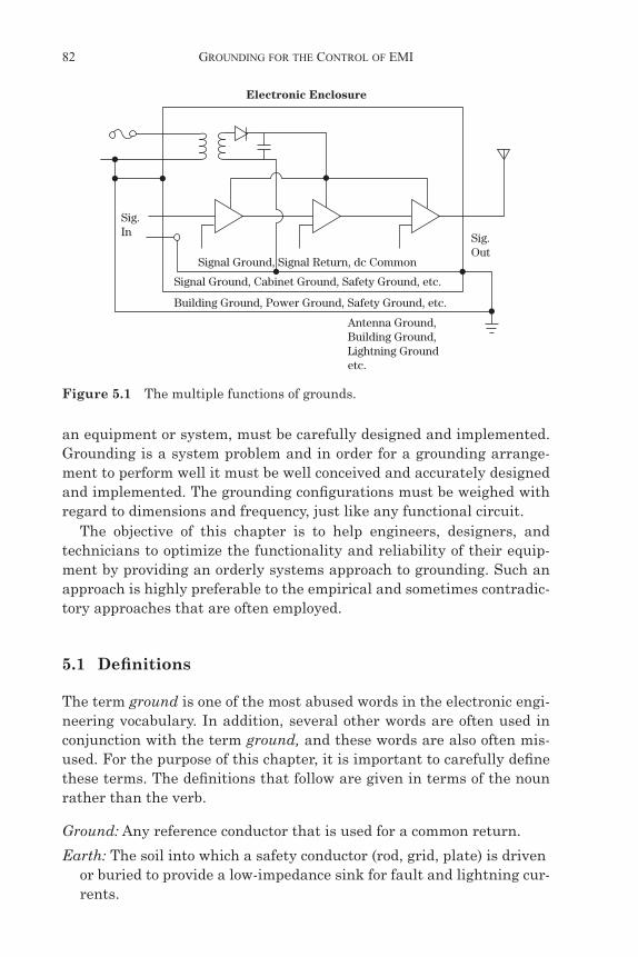
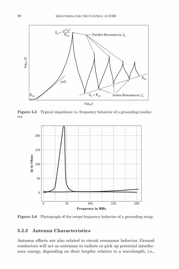
Typical ground networks are complex circuits of Rs, Ls, and Cs withfrequency-dependent properties including both parallel and series reso-nances. These resonances are important to the performance of a groundnetwork. Resonance effects in a grounding path are illustrated inFig. 5.5. The relative effectiveness of a grounding conductor as a func-tion of frequency is directly related to its impedance behavior (Fig. 5.6).It is evident from Figs. 5.5 and 5.6 that, for maximum efficiency, groundconductor lengths should be a small portion of the wavelength at thefrequency of the signal of concern. The most effective performance isobtained at frequencies well below the first resonance.
L C⁄
LC
Duff.book Page 89 Friday, January 28, 2011 2:18 PM
90 GROUNDING FOR THE CONTROL OF EMI
5.2.2 Antenna Characteristics
Antenna effects are also related to circuit resonance behavior. Groundconductors will act as antennas to radiate or pick up potential interfer-ence energy, depending on their lengths relative to a wavelength, i.e.,
Parallel Resonances, fp
R dc
R ac
R ac
Zp =
Zs = Series Resonances, fs
Rac
flog10
log 1
0 | Z
|
jw L
w 2 L2
Figure 5.5 Typical impedance vs. frequency behavior of a grounding conduc-tor.
200
150
100
50
0
0 50 100 150 200
| Z| i
n O
hms
Frequency in MHz
Figure 5.6 Photograph of the swept frequency behavior of a grounding strap.
Duff.book Page 90 Friday, January 28, 2011 2:18 PM
GROUND-RELATED INTERFERENCE 91
their efficiency. This fact permits a wavelength-to-physical-length ratioto be derived for ground conductors. The efficiency of a conductor as anantenna is related to its radiation resistance. Radiation resistance is adirect measure of the energy radiated from the antenna. A good mea-sure of performance for a wire is a quarter-wave monopole, which has aradiation resistance of 36.5 '. An antenna that transmits or receives 10percent or less than a monopole can be considered to be inefficient. Tobe effective, a ground wire should be an inefficient antenna. A conve-nient criterion for a poor antenna, i.e., a good ground wire, is that itslength be %/10 or less. Thus, a recommended goal in the design of aneffective grounding system is to maintain ground wires exposed topotentially interfering signals at lengths less than 1/10 of a wavelengthof the interfering signal.
5.3 Ground-Related Interference
Interference is any extraneous electrical or electromagnetic disturbancethat tends to disrupt the reception of desired signals or produces undesir-able responses in a circuit or system. Interference can be produced byboth natural and man-made sources, either external or internal to thecircuit. The correct operation of complex electronic equipment and facili-ties is inherently dependent upon the frequencies and amplitudes of boththe signals utilized in the system and the potential interference emis-sions that are present. If the frequency of an undesired signal is withinthe operating frequency range of a circuit, the circuit may respond to theundesired signal (it may even happen out of band). The severity of theinterference is a function of the amplitude and frequency of the undes-ired signal relative to that of the desired signal at the point of detection.
Ground-related interference often involves one of two basic couplingmechanisms. The first mechanism results from the fact that the signalcircuits of electronic equipments share the ground with other circuits orequipments. This mechanism is called common-ground impedance cou-pling. Any shared impedance can provide a mechanism for interferencecoupling. Figure 5.7 illustrates the mechanism by which interference iscoupled between culprit and victim circuits via the common-groundimpedance. In this case, the interference current, I, flowing through thecommon-ground impedance, Z, will produce an interfering signal volt-age, Vc, in the victim circuit. It should be emphasized that the interfer-ence current flowing in the common impedance may be either a currentthat is related to the normal operation of the culprit circuit or an inter-mittent current that occurs due to abnormal events (lightning, powerfaults, load changes, power line transients, etc.).
Duff.book Page 91 Friday, January 28, 2011 2:18 PM

92 GROUNDING FOR THE CONTROL OF EMI
Even if the equipment pairs do not use the signal ground as the sig-nal return, the signal ground can still be the cause of coupling betweenthem. Figure 5.8 illustrates the effect of a stray current, IR, flowing inthe signal ground. The current IR may be the result of the direct cou-pling of another equipment pair to the signal ground. It may be theresult of external coupling to the signal ground, or induced in theground by an incident field. In either case, IR produces a voltage VN inthe ground impedance ZR. This voltage produces a current in the inter-connecting loop, which in turn develops a voltage across ZL in Equip-ment B. Thus, it is evident that interference can conductively couplethrough the signal ground to all circuits and equipment connectedacross the non-zero impedance elements of that ground.
V2 Vc
Z
V1
Rg1
Rg2
RL2Vi
I1 + I2
RL1
I1
I2
Finite Common Impedancein GroundCulprit
Source
VictimReceptor
Figure 5.7 Common-mode impedance coupling between circuits.
VS
ZR
VN
ZL VL VN
IR
Z
+
+
+
–
–
Z
Ground
Equipment A Equipment B
Figure 5.8 Conductive coupling of extraneous noise into equipment intercon-necting cables.
Duff.book Page 92 Friday, January 28, 2011 2:18 PM
GROUND-RELATED INTERFERENCE 93
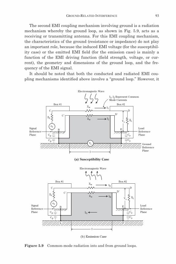
The second EMI coupling mechanism involving ground is a radiationmechanism whereby the ground loop, as shown in Fig. 5.9, acts as areceiving or transmitting antenna. For this EMI coupling mechanism,the characteristics of the ground (resistance or impedance) do not playan important role, because the induced EMI voltage (for the susceptibil-ity case) or the emitted EMI field (for the emission case) is mainly afunction of the EMI driving function (field strength, voltage, or cur-rent), the geometry and dimensions of the ground loop, and the fre-quency of the EMI signal.
It should be noted that both the conducted and radiated EMI cou-pling mechanisms identified above involve a “ground loop.” However, it
(a) Susceptibility Case
B
DD´
ESignalReferencePlane
LoadReferencePlane
GroundReferencePlane
I2
I1, I2 Represent CommonMode Currents
Electromagnetic Wave
C
FA
C´
Box #1 Box #2
I
Zw
ZS
Cp
Cp
I1
Vo
Cp
Cp
Zw ZL
eS
Vi
(b) Emission Case
B
DD´
ESignalReferencePlane
LoadReferencePlane
IR
IG
Electromagnetic Wave
C
FA
C´
Box #1 Box #2
I
Zw
ZS
Cp
Cp
IS
Vo
Cp
Cp
Zw ZL
eS
Figure 5.9 Common-mode radiation into and from ground loops.
Duff.book Page 93 Friday, January 28, 2011 2:18 PM
94 GROUNDING FOR THE CONTROL OF EMI
should be recognized that ground loop EMI problems can exist withouta physical connection to ground. In particular, at RF frequencies, dis-tributed capacitance to ground can create a ground loop condition eventhough circuits or equipments are floated with respect to ground.
Also, it should be noted that, for both of the EMI coupling mecha-nisms involving the ground loop, the EMI currents in the signal leadand the return are flowing in the same direction. This EMI condition(where the currents in the signal lead and the return are in phase) isreferred to as common-mode EMI. The EMI control techniques that willbe effective for ground loop problems are those that either reduce thecoupling of EMI into the ground loop or provide suppression of the com-mon-mode EMI that is coupled into the ground loop.
5.4 Circuit, Equipment, and System Grounding
In the previous section, EMI coupling mechanisms resulting from cir-cuit, equipment, and system grounding were identified and discussed.At this point, it should be obvious that grounding is very importantfrom the standpoint of minimizing and controlling EMI. However,grounding is one of the least understood and most significant culprits inmany system-level EMI problems. The grounding scheme of a systemmust perform the following functions:
• Analog, low-level, and low-frequency circuits must have noise-free dedicated returns. Due to the low frequencies involved, wires are generally used (more or less dictating a single-point or star ground system).
• Analog high-frequency circuits {radio, video, etc.} must have low-impedance, noise-free return circuits, generally in form of planes or coaxial cables.
• Returns of logic circuits, especially high-speed logic, must have low impedances over the whole bandwidth (dictated by the fastest rise times), since power and signal returns share the same paths.
• Returns of powerful loads (solenoids, motors, lamps, etc.) should be distinct from any of the above, even though they may end up in the same terminal of the power supply regulator.
• Return paths to chassis of cable shields, transformer shields, filters, etc. must not interfere with functional returns.
• When the electrical reference is distinct from the chassis ground, provision and accessibility must exist to connect and disconnect one from the other.
Duff.book Page 94 Friday, January 28, 2011 2:18 PM
CIRCUIT, EQUIPMENT, AND SYSTEM GROUNDING 95
• More generally, for signals that communicate within the equipment or between parts of a system, the grounding scheme must provide a common reference with minimum ground shift (unless these links are balanced, optically isolated, etc.). Minimum ground shift means that the common-mode voltage must stay below the sensitivity threshold of the most susceptible device in the link.
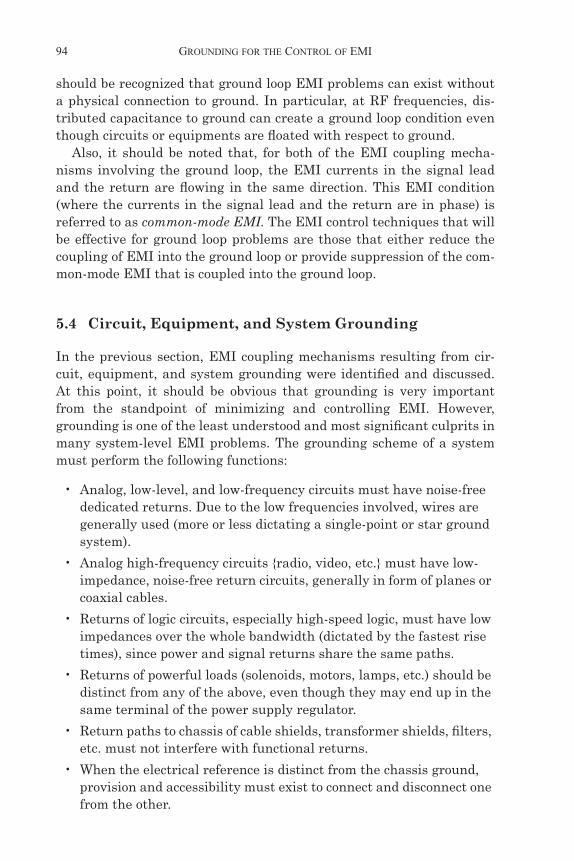
All the above constraints can be accommodated if their functionalreturns and protective grounds are integrated into a grounding systemhierarchy as shown in Fig. 5.10. The application of this concept is thesubject of the following discussion.
Modern electronic systems seldom have only one ground. To miti-gate interference, such as due to common-mode impedance coupling, asmany separate grounds as possible are used. Separate grounds in eachsubsystem for structural grounds, signal grounds, shield grounds, andprimary and secondary power grounds are desirable if economicallyand logistically practical. These individual grounds from each sub-system are finally connected by the shortest route back to the systemground point, where they form an overall system potential reference.
Low-Level,Low-FrequencyGround(mV to mVdc to a few 100 kHz)
Relays, etc. . . .,Signaling Grounds(5 V to 50 Vdc to a few kHz)
Lightning, EMPGround(Tens of kA,dc to a few tens of MHz)
DC Power Ground(Returns for Loads > 1 A)
AC Power Safety Ground(50 Hz/60 Hz or 400 Hz)
Low-LevelHigh-FrequencyGround.Radio Communication(mV to mV, kHz to GHz)
Digital Levels,High-FrequencyGround.(Volts, dc to 100 MHz)
Figure 5.10 Grounding hierarchy.
Duff.book Page 95 Friday, January 28, 2011 2:18 PM
96 GROUNDING FOR THE CONTROL OF EMI
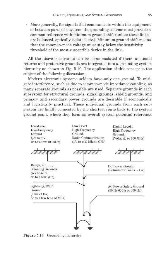
This method is known as a single-point ground and is illustrated inFig. 5.11.
5.4.1 Single-Point Grounding Scheme
The single-point or star type of grounding scheme shown in the figureavoids problems of common-mode impedance coupling discussed in theprevious section. The only common path is in the earth ground (forearth-based structures), but this usually consists of a substantial con-ductor of very-low impedance. Thus, as long as no or low ground cur-rents flow in any low-impedance common paths, all subsystems orequipments are maintained at essentially the same reference potential.
The problem of implementing the above single-point groundingscheme comes about when (1) interconnecting cables are used, espe-cially ones having cable shields that have lengths on the order of 1/20 ofa wavelength or greater, and (2) parasitic capacitance exists betweensubsystem or equipment housings or between subsystems and thegrounds of other subsystems. This situation is illustrated in Fig. 5.12.Here, cable shields connect some of the subsystems together so thatmore than one grounding path from a particular subsystem to theground point exists. Unless precautions are taken, common-impedanceground currents could flow. At high frequencies, the parasitic capacitivereactance represents low-impedance paths, and the bond inductance ofa subsystem-to-ground point results in higher impedances. Thus, again,common-mode currents may flow or unequal potentials may developbetween subsystems.
System (or Subsystem)Ground Point
Subsystem(or Equipment)
#1
Subsystem(or Equipment)
#2
Subsystem(or Equipment)
#3
Subsystem(or Equipment)
#4
Prime PowerGenerator
Subsystem(or Equipment)
#N
EarthGround
Figure 5.11 Single-point or star grounding arrangement.
Duff.book Page 96 Friday, January 28, 2011 2:18 PM

CIRCUIT, EQUIPMENT, AND SYSTEM GROUNDING 97
5.4.2 Multipoint Grounding Scheme
Rather than have an uncontrolled situation as shown in Fig. 5.12, theother grounding alternative is multipoint grounding as illustrated inFig. 5.13. For the example shown in Fig. 5.13, each equipment or sub-system is bonded as directly as possible to a common low-impedance
System (or Subsystem)Ground Point
ParasiticCapacitance
Subsystem(or Equipment)
# 1
Interconnecting Cable Parasitic Capacitance
Subsystem(or Equipment)
# 2
Subsystem(or Equipment)
# 3
Subsystem(or Equipment)
# 4
Prime PowerGenerator
Subsystem(or Equipment)
# N
EarthGround
Figure 5.12 Degeneration of single-point ground by interconnecting cables and parasitic capacitance.
InterconnectingCables
Ground Plane
Ground Plane
EarthGround
Subsystem(or Equipment)
# 1
Subsystem(or Equipment)
# 2
Subsystem(or Equipment)
# 3
Subsystem(or Equipment)
# 4
Prime PowerGenerator
Subsystem(or Equipment)
# N
Ground Lugs orBonds on Unit Frame
Grounds
Figure 5.13 Multipoint grounding system.
Duff.book Page 97 Friday, January 28, 2011 2:18 PM

98 GROUNDING FOR THE CONTROL OF EMI
ground plane to form a homogeneous, low-impedance path. Thus, com-mon-mode currents and other EMI problems will be minimized. Theground plane then is earthed for safety purposes.
5.4.3 Selection of a Grounding Scheme
The facts are that a single-point grounding scheme operates better atlow frequencies, and a multipoint ground behaves best at high frequen-cies. If the overall system, for example, is a network of audio equip-ment, with many low-level sensors and control circuits behaving asbroadband transient noise sources, then the high-frequency perfor-mance is irrelevant, since no receptor responds above audio frequency.For this situation, a single-point ground would be effective. Conversely,if the overall system were a receiver complex of 30 to 1,000 MHz tuners,amplifiers, and displays, then low-level, low-frequency performance isirrelevant. Here, multipoint grounding applies, and interconnectingcoaxial cables should be used.
The above comparison of audio versus VHF/UHF systems makesclear the selection of the correct approach. The problem then narrowsdown to one of defining where low- and high-frequency crossover existsfor any given subsystem or equipment. The answer here in partinvolves the highest significant operating frequency of low-level circuitsrelative to the physical distance between the farthest located equip-ments. The determination of the crossover frequency region involvesconsideration of (1) magnetic versus electric field coupling problemsand (2) ground-plane impedance problems due to separation. Hybridsingle and multipoint grounding systems are often the best approachfor crossover region applications.
When printed circuits and ICs are used, network proximity is consid-erably closer. Thus, multipoint grounding is more economical and prac-tical to produce per card, wafer, or chip. Interconnection of thesecomponents through wafer risers, motherboards, etc. should use agrounding scheme following the illustrations of previous paragraphs.This will likely still represent a multipoint or hybrid groundingapproach in which any single-point grounding (for hybrid grounds), ifused, would be to avoid low-frequency ground current loops and/or com-mon-mode impedance coupling.
In summary, many system-level EMI problems can be avoided bypaying careful attention to the grounding scheme used. Common-mode,common-ground impedance problems may be reduced by application ofone or more of the following techniques.
Duff.book Page 98 Friday, January 28, 2011 2:18 PM

CIRCUIT, EQUIPMENT, AND SYSTEM GROUNDING 99
• Eliminate common impedance by using a single point ground (Fig. 5.11) if possible. This configuration is usually optimal for power frequencies and signal frequencies below 300 kHz.
• Separate and isolate grounds on the basis of signal type, level, and frequency as illustrated in Fig. 5.10.
• Minimize ground impedance as illustrated in Fig. 5.14 by using ground bus, ground plane, or ground grid.
• Float circuits or equipments if practical from a safety standpoint as illustrated in Fig. 5.15. The effectiveness of floating circuits or equipments depends on their physical isolation from other conduc-tors. In large facilities, it is difficult to achieve a floating system.
• Use an inductor or capacitor in the ground connection to provide high- or low-frequency isolation, respectively, as illustrated in Figs. 5.16 and 5.17.
Daisy Chaining (Poor)
Heavier Ground Path (Better)
Ground Plane (Better Still) Ground Grid (Better Still)
Parallel Ground Wires (Better)or:
Figure 5.14 Means of decreasing common-impedance coupling by decreasing ground path impedance. From the bad practice of daisy-chain (top), the improvement evolves toward a plane (left) or a grid (right).
Duff.book Page 99 Friday, January 28, 2011 2:18 PM

100 GROUNDING FOR THE CONTROL OF EMI
• Use filters or ferrites in ground loops to limit common-mode cur-rents or provide a common-mode voltage drop.
• Use a common-mode choke as illustrated in Fig. 5.18 or a common-mode isolation transformer as illustrated in Fig. 5.19 to suppress ground-loop EMI. These devices may provide on the order of 60 dB
Box 1 Box 2
Vi
Zs
ZL Vo
Float
Case
(a) Float Equipment Enclosures
Safety BusZ
(b) Float Circuits and Boards
Box 1 Box 2
Vi
Float
Figure 5.15 Float circuits or equipments.
Rs
RLVs
Figure 5.16 Capacitive grounding.
Duff.book Page 100 Friday, January 28, 2011 2:18 PM

CIRCUIT, EQUIPMENT, AND SYSTEM GROUNDING 101
RL
RF Choke
Vs
Figure 5.17 Inductive grounding.
In
Vn
Vs
Rs
IsI”n
I’n Is
RL
••
Figure 5.18 Common-mode chokes.
A
B
C
DCase
Victim
Victim
D
CA
B
OrdinaryIsolationTransformer
Or GreenWire
Primary Secondary
ParasiticCap
=
en
Figure 5.19 Common-mode isolation transformer.
Duff.book Page 101 Friday, January 28, 2011 2:18 PM

102 GROUNDING FOR THE CONTROL OF EMI
of common-mode rejection at frequencies up to several hundred kilohertz.
• Use optical isolators and/or fiber optics to block common-mode EMI effects as illustrated in Fig. 5.20. Optical isolators provide a high degree of common-mode rejection at frequencies up to and including the HF band (i.e., 3 to 30 MHz). Optical isolators are usually lim-ited to digital applications (they are not applicable to low-level ana-log circuits).
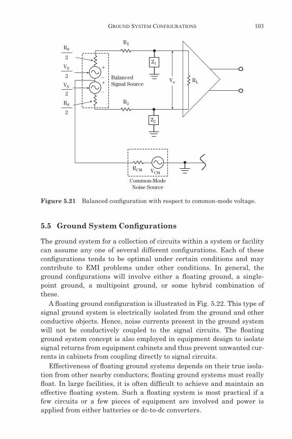
• Use balanced circuits to minimize effects of common-mode EMI in the ground loop as illustrated in Fig. 5.21. With a perfectly bal-anced circuit, the currents flowing in the two parts of the circuit will produce equal and opposite voltages across the load, so the resulting voltage across the load is zero. Balanced circuits can pro-vide significant (greater than 20 dB) common-mode reduction for low-frequency conditions. However, at higher frequencies (above 30 MHz), other effects start to predominate, and the effectiveness of balanced circuits diminishes.
Common-mode radiated EMI effects resulting from emissions thatare radiated or picked up by a ground loop may be reduced by the appli-cation of one or more of the following techniques:
• Minimize the common-mode ground loop area by routing intercon-necting wires or cable close to the ground.
• Reduce the common-mode ground loop currents by floating circuits or equipments; using optical isolators; or inserting common-mode filters, chokes, or isolation transformers.
• Use balanced circuits or balanced drivers and receivers.
Figure 5.20 Use of optical isolation to combat common-mode impedance.
Duff.book Page 102 Friday, January 28, 2011 2:18 PM
GROUND SYSTEM CONFIGURATIONS 103
5.5 Ground System Configurations
The ground system for a collection of circuits within a system or facilitycan assume any one of several different configurations. Each of theseconfigurations tends to be optimal under certain conditions and maycontribute to EMI problems under other conditions. In general, theground configurations will involve either a floating ground, a single-point ground, a multipoint ground, or some hybrid combination ofthese.
A floating ground configuration is illustrated in Fig. 5.22. This type ofsignal ground system is electrically isolated from the ground and otherconductive objects. Hence, noise currents present in the ground systemwill not be conductively coupled to the signal circuits. The floatingground system concept is also employed in equipment design to isolatesignal returns from equipment cabinets and thus prevent unwanted cur-rents in cabinets from coupling directly to signal circuits.
Effectiveness of floating ground systems depends on their true isola-tion from other nearby conductors; floating ground systems must reallyfloat. In large facilities, it is often difficult to achieve and maintain aneffective floating system. Such a floating system is most practical if afew circuits or a few pieces of equipment are involved and power isapplied from either batteries or dc-to-dc converters.
Z1
Z2
Vo RL
R1RS
VS
VS
2
2
2
2
RSR2
_
_
+
+BalancedSignal Source
Common-ModeNoise Source
RCM VCM
Figure 5.21 Balanced configuration with respect to common-mode voltage.
Duff.book Page 103 Friday, January 28, 2011 2:18 PM

104 GROUNDING FOR THE CONTROL OF EMI
A single-point ground for an equipment complex is illustrated inFig. 5.23. With this configuration, the signal circuits are referenced to asingle point, and this single point is then connected to the facilityground. The ideal single-point signal ground network is one in whichseparate ground conductors extend from one point on the facilityground to the return side of each of the numerous circuits locatedthroughout a facility. This type of ground network requires anextremely large number of conductors and is not generally economicallyfeasible. In lieu of the ideal, various degrees of approximation to single-point grounding are employed.
Figure 5.22 Floating Signal Ground.
Signal Ground
Structure or other Grounded Objects
Equipment
Figure 5.23 Single-point signal ground.
Duff.book Page 104 Friday, January 28, 2011 2:18 PM
GROUND SYSTEM CONFIGURATIONS 105
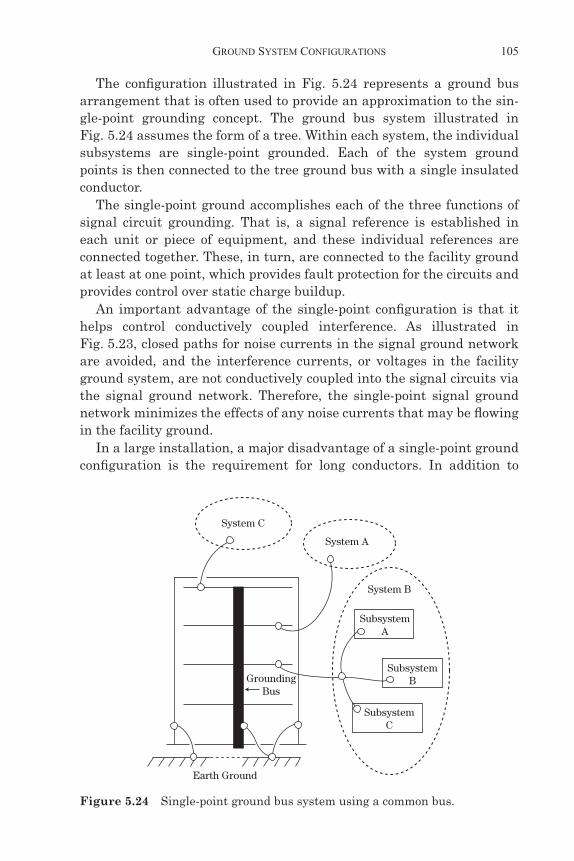
The configuration illustrated in Fig. 5.24 represents a ground busarrangement that is often used to provide an approximation to the sin-gle-point grounding concept. The ground bus system illustrated inFig. 5.24 assumes the form of a tree. Within each system, the individualsubsystems are single-point grounded. Each of the system groundpoints is then connected to the tree ground bus with a single insulatedconductor.
The single-point ground accomplishes each of the three functions ofsignal circuit grounding. That is, a signal reference is established ineach unit or piece of equipment, and these individual references areconnected together. These, in turn, are connected to the facility groundat least at one point, which provides fault protection for the circuits andprovides control over static charge buildup.
An important advantage of the single-point configuration is that ithelps control conductively coupled interference. As illustrated inFig. 5.23, closed paths for noise currents in the signal ground networkare avoided, and the interference currents, or voltages in the facilityground system, are not conductively coupled into the signal circuits viathe signal ground network. Therefore, the single-point signal groundnetwork minimizes the effects of any noise currents that may be flowingin the facility ground.
In a large installation, a major disadvantage of a single-point groundconfiguration is the requirement for long conductors. In addition to
System C
System A
System B
SubsystemA
GroundingBus
Earth Ground
SubsystemB
SubsystemC
Figure 5.24 Single-point ground bus system using a common bus.
Duff.book Page 105 Friday, January 28, 2011 2:18 PM

106 GROUNDING FOR THE CONTROL OF EMI
being expensive, long conductors prevent realization of a satisfactoryreference for higher frequencies because of large self-impedances. Fur-thermore, because of stray capacitance between conductors, single-point grounding essentially ceases to exist as the signal frequency isincreased. In general, for typical equipments, systems, or facilities, sin-gle-point grounds tend to be optimum for frequencies below approxi-mately 300 kHz.
The multiple-point ground illustrated in Fig. 5.25 is the third config-uration frequently used for signal ground networks. This configurationestablishes many conductive paths to various electronic systems or sub-systems within a facility. Within each subsystem, circuits and networkshave multiple connections to this ground network. Thus, in a facility,numerous parallel paths exist between any two points in the multiple-point ground network.
Multiple-point grounding frequently simplifies circuit constructioninside complex equipment. It permits equipment employing coaxialcables to be interfaced more easily, since the outer conductor of thecoaxial cable does not have to be floated relative to the equipment cabi-net or enclosure.
However, multiple-point grounding suffers from an important disad-vantage. Power currents and other high-amplitude, low-frequency cur-rents flowing through the facility ground system can conductivelycouple into signal circuits to create intolerable interference in suscepti-ble low-frequency circuits. Also, multiple ground loops are created, andthis makes it more difficult to control radiated emission or susceptibil-ity resulting from the common-mode ground loop effects. In addition,
Facility Ground
Signal Ground
Equipment
Safe
ty G
roun
d
Figure 5.25 Multiple-point ground configuration.
Duff.book Page 106 Friday, January 28, 2011 2:18 PM

GROUND SYSTEM CONFIGURATIONS 107
for multiple-point grounding to be effective, all ground conductorsbetween the separate points must be less than 0.1 wavelength of theinterference signal. Otherwise, common-ground impedance and ground-radiated effects will become significant. In general, multiple-pointgrounding configurations tend to be optimum at higher frequencies (i.e.,above 30 MHz).
To illustrate one form of a hybrid-ground system, Fig. 5.26 shows a19-in cabinet rack containing five separate sliding drawers. Eachdrawer contains a portion of the system (top to bottom): (1) RF and IFpreamp circuitry for reception of microwave signals, (2) IF and video
Single-Point Power Line & Gnd Return (SPPL&GR)
LO
BPF &RF Ampl
Pre-Selector
AntIn
IFPreampMixer
IFAmpl.
Log IFAmpl.
Demod-ulator
VideoAmpl.
SweepCircuits
CRODriver
DiffAmpl.
Recorders
Multipoint Ground Plane
Pow
er G
roun
d
Sign
al G
roun
d
Singlepoint Ground Plane
Singlepoint Ground Plane
SPPL&GR Multipoint Ground Plane
DisplayDrawer
EarthGround Distribution Block
Gnd
AudioDriver
A
A B
B
Figure 5.26 Grounding arrangement used in cabinet racks.
Duff.book Page 107 Friday, January 28, 2011 2:18 PM

108 GROUNDING FOR THE CONTROL OF EMI
signal amplifiers, (3) display drivers, displays, and control circuits, (4)low-level audio circuits and recorders for documenting sensitive multi-channel, hard-line telemetry sensor outputs, and (5) secondary and reg-ulated power supplies. The hybrid aspect results from:
• The RF and IF video drawers are similar. Here, unit-level boxes or stages (interconnecting coaxial cables are grounded at both ends) are multipoint grounded to the drawer-chassis ground plane. The chassis is then grounded to the dagger pin, chassis ground bus as suggested in Fig. 5.27. The power ground to these drawers, on the other hand, is using a single-point ground from its bus in a manner identical to the audio drawer.
Insulator
Antenna Jack
ComputerClock Input
Multiplex InputSensor Jack
AC PowerMains Input
Sign
al G
nd
Cha
ssis
She
lves
of R
ails
Pow
erR
acew
ay
Low-Level RF Circuits & IFPreamp
To Power GndTo Signal Gnd
RF-IF Coax Cables
IF Amplifiers, BP FiltersDemodulators, & Video Ampl
Video Cables, Coax or TwistedShielded Pair
Display Drivers andReadout Circuitry
Low-Level AudioSensor Circuits & Display
Ground orEarthing
Stake
Weld
Ground Distribution Block
Secondary & RegulatedPower Supplies
Figure 5.27 Block diagram detail of hybrid grounding arrangement.
Duff.book Page 108 Friday, January 28, 2011 2:18 PM

EMI CONTROL DEVICES AND TECHNIQUES 109
• The chassis or signal ground and power ground busses each consti-tute a multipoint grounding scheme to the drawer level. The indi-vidual ground busses are single-point grounded at the bottom ground distribution block. This avoids circulating common-mode current between chassis or signal ground and power grounds, since power ground current can vary due to transient surges in certain modes of equipment operation.
• Interconnecting cables between different drawer levels are run sep-arately, and their shields, when used, are treated in the same grounding manner as at the drawer level.
• The audio and display drawers shown in Fig. 5.27 use single-point grounding throughout for both their unit-level boxes (interconnect-ing twisted cable is grounded at one end to its unit) and power leads. Cable and unit shields are all grounded together at the com-mon dagger pin bus. Similarly, the outgoing power leads and twisted returns are separately bonded on their dagger pin busses.
To review the above scheme, the following is observed:
• The audio and display drawers have ground runs of about 0.6 m and an upper frequency of operation of about 1 MHz (driver and sweep circuits). Thus, single-point grounding to the strike pins is indicated.
• The RF and IF drawers process UHF and 30 MHz signals over a distance of a meter so that multipoint grounding is indicated.
• The regulated power supplies furnish equipment units having tran-sient surge demands. The longest length is about 1.5 m, and signifi-cant transient frequency components may extend up in the HF region. Here, hybrid grounding is indicated: single-point within a drawer and multipoint from the power bus to all drawers.
5.6 EMI Control Devices and Techniques
The performance of some EMI control techniques or devices may be sig-nificantly influenced by grounding. In particular, cable shields; isola-tion transformers; EMI filters; ESD, lightning, and EMF protectiontechniques; and Faraday shields must be properly grounded so as toprovide maximum EMI protection. A detailed discussion of specificgrounding considerations associated with these EMI control techniquesor devices is beyond the scope of this book. However, it is important toemphasize the importance of grounding on the performance of thesetechniques or devices, and details may be found in the references.
Duff.book Page 109 Friday, January 28, 2011 2:18 PM
110 GROUNDING FOR THE CONTROL OF EMI
Suggested Readings: Grounding
[1] Morrison, Ralph, and W. H. Lewis, Grounding and Shielding inFacilities, Hoboken, NJ: John Wiley & Sons, 1990.
[1] Morrison, Ralph, Grounding and Shielding Techniques in Instru-mentation, 3rd ed., Hoboken, NJ: John Wiley & Sons, 1990.
[1] Denny, Hugh W., Grounding for the Control of EMI, Gainesville,VA, Interference Control Technologies, Inc.
[1] Grounding, Bonding and Shielding for Electronic Equipment andFacilities, MIL-HDBK-419.
Duff.book Page 110 Friday, January 28, 2011 2:18 PM