EMF Equation
27
description
electrical engineering
Transcript of EMF Equation


• EMF induced in DC generator:
Directly proportional to flux per pole (Ф). Directly proportional to speed (N).

• Polarity of the induced emf:
Depends on the direction of magnetic field.Depends on the direction of rotation.

DC machines – split ring commutators are used.

No rate of change of flux , EMF =0

Maximum rate of change of flux, EMF = Maximum

Positive and negative half cycles

• In the first half of the revolution , current flows always along ABLMCD i.e. brush no 1 in contact with segment a.
• In the next half revolution, the direction of the induced current in the coil is reversed.
• But at the same time the position of the segments a and b are also reversed which results that brush no 1 comes in touch with that segment b.
• Hence, the current in the load resistance again flows from L to M.


EMF Equation
Let,
Ø= flux per pole in weber
Z = Total number of conductor
P = Number of poles
A = Number of parallel paths
N =armature speed in rpm
Eg = emf generated in any on of the parallel path

Flux cut by 1 conductor in 1 revolution = P * φ
Flux cut by 1 conductor in 60 sec = P φ N /60
Avg emf generated in 1 conductor = PφN/60
Number of conductors in each parallel path = Z /A
Eg = PφNZ/60A

Armature ReactionInteraction of Main field flux with Armature field flux


• Methods of excitation ( Supply to field winding)
• In a separately excited DC generator, the field winding is excited by an external independent source.

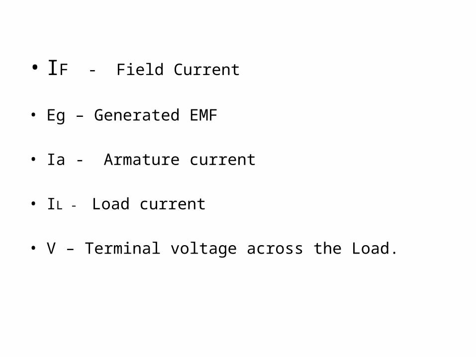
• IF - Field Current
• Eg – Generated EMF
• Ia - Armature current
• IL - Load current
• V – Terminal voltage across the Load.

Self-excited DC Generators
• These are the generators whose field magnets are energized by the current supplied by themselves.
• In these type of machines field coils are internally connected with the armature.
• Due to residual magnetism some flux is always present in the poles.

Shunt-Wound Generators

• Field coils are connected across the output voltage of the armature.
• In a shunt-wound generator, the field coils consist of many turns of small wire as less amount of current flow through it.
• If Ia=100 A, then If = 2 to 10 A (approx.)

Series-Wound Generators

• In these type of generators, the field windings are connected in series with armature conductors.
• So, whole armature current flows through the field coils as well as the load.
• As series field winding carries full load current, it is designed with relatively few turns of thick wire.
• The resistance of series field winding is therefore
very low (nearly 0.5Ω ).

Compound wound dc generator

• Compound wound generators have both series field winding and shunt field winding.
• One winding is placed in series with the armature and the other is placed in parallel with the armature

The generators in which only shunt field winding is in parallel with the armature winding
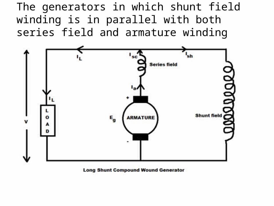
The generators in which shunt field winding is in parallel with both series field and armature winding


• When the series field assists the shunt field, generator is said to be commutatively compound wound.
• If series field opposes the shunt field, the generator is said to be differentially compound wound.