Emergency Valve 2000
8
2000 Emergency Valve
Transcript of Emergency Valve 2000

2000Emergency Valve

2
The Company
Production, R+D+i, evolution
VALVULAS NACIONAL, S.A. was established in Spain in 1976. The main target was to assist the petrochemical and chemical industries emerging in Spain at that time. Right from the start VALVULAS NACIONAL, S.A., has been designing and producing safety valves according to most recognized international standards and norms: API, ASME, ASTM and the European directives 2014/68/UE and 2014/34/UE. Our pro-duction process is accredited by an ISO 9001-201 5 certification.
Our know how and capacity to adapt to the constantly changing demands of the market, made possible the introduction of new products designed for new applica-tions on the market, like THERMOSOLAR PLANTS, where VALVULAS NACIONAL has supplied safety valves to more than 31 complete plants all over the world, while at the same time continuously supplying to all main players of the Spanish petroche-mical, chemical and refining industries.
Production capacity
VALVULAS NACIONAL, S.A. valves’ have their discharge coefficients approved in laboratory tests, in order to guarantee and assure that correct values are being used for every sizing process.In our Technical sales department we count with a modern software which allows us to verify all the possibilities, and to assure strict fulfillment of all international standards.VALVULAS NACIONAL, S.A. has established representation agreements with the most important O.E.M. companies in the safety sector of the industry, consolidating us as one of the main companies by product range; design and consulting in new plants or in new process.Our continuous growth, shows a clear trend, which confirms the integration of our workers to provide first class service to our customers and partners.
Factory & location
Our facilities in Rubí (Barcelona - Spain), with more than 3.000 Sq m are fully prepa-red for our production activities: machining with modern CNC, assembling and tes-ting. We also have long term agreements with approved workshops, which provides us with flexibility and fast feedback to customers demands, with fullquality guarantee which has always been our main target.
Strategic alliances
Nowadays VALVULAS NACIONAL, S.A. starts an internationalization process, establishing representation agreements in different countries and continents all over the world, with specialized companies that will provide added value in our service towards the end user.
VALVULAS NACIONAL Making safety since 1976!
2
2
The Company
Production, R+D+i, evolution
VALVULAS NACIONAL, S.A. was established in Spain in 1976. The main target was to assist the petrochemical and chemical industries emerging in Spain at that time. Right from the start VALVULAS NACIONAL, S.A., has been designing and producing safety valves according to most recognized international standards and norms: API, ASME, ASTM and the European directives 2014/68/UE and 2014/34/UE. Our pro-duction process is accredited by an ISO 9001-201 5 certification.
Our know how and capacity to adapt to the constantly changing demands of the market, made possible the introduction of new products designed for new applica-tions on the market, like THERMOSOLAR PLANTS, where VALVULAS NACIONAL has supplied safety valves to more than 31 complete plants all over the world, while at the same time continuously supplying to all main players of the Spanish petroche-mical, chemical and refining industries.
Production capacity
VALVULAS NACIONAL, S.A. valves’ have their discharge coefficients approved in laboratory tests, in order to guarantee and assure that correct values are being used for every sizing process.In our Technical sales department we count with a modern software which allows us to verify all the possibilities, and to assure strict fulfillment of all international standards.VALVULAS NACIONAL, S.A. has established representation agreements with the most important O.E.M. companies in the safety sector of the industry, consolidating us as one of the main companies by product range; design and consulting in new plants or in new process.Our continuous growth, shows a clear trend, which confirms the integration of our workers to provide first class service to our customers and partners.
Factory & location
Our facilities in Rubí (Barcelona - Spain), with more than 3.000 Sq m are fully prepa-red for our production activities: machining with modern CNC, assembling and tes-ting. We also have long term agreements with approved workshops, which provides us with flexibility and fast feedback to customers demands, with fullquality guarantee which has always been our main target.
Strategic alliances
Nowadays VALVULAS NACIONAL, S.A. starts an internationalization process, establishing representation agreements in different countries and continents all over the world, with specialized companies that will provide added value in our service towards the end user.
VALVULAS NACIONAL Making safety since 1976!
2 3
Index
GENERAL FEATURES & DESCRIPTION 4
DIMENSION 5
BILL OF MATERIALS 6
DEFINITIONS 7
Making safety since 1976
VALVULAS NACIONAL

General FeaturesProduct Introduction
The emergency valve, model “PH”, is a safety device inten-ded for installation on storage tanks with the fi nality of assure a quick evacuation of large volume of fl uid inside the tank in the event of an overpressure due to fi re condition.Another purpose is that due to its peculiar design and size, it can be used as a manhole cover, allowing access to the interior of the container. That allows easily to do maintenance and inspection of the interior of the tank.
Description
The emergency valve “PH” is designed in such a way that its opening occurs when the fl uid contained in the tank creates a pressure higher than its set pressure value. When the over-pressure causes more force on the valve disc than the wei-ght of the valve, the disc will rise, allowing fl uid leakage and, consequently, relief of overpressure. The valve will be closed again, once the pressure inside the tank has stabilized.The emergency valve basically consists of a fl anged body to install the valve to the tank. A weight controlled fl oating disc, attached by a link to the manual opening lever, which in turn is attached to the body by a hinge. The sealing of the seal between the cover and the body is produced by means of a diaphragm or oring.The quality of the materials and the sealing elastomer are defi ned according to the pressure, temperature and chemi-cal characteristics of the product stored in the tank to which the valve is to protect.Because the cover is electrically isolated from the valve body by the sealing diaphragm and by the hinge friction bushes, which are made of PTFE, a ground cable is installed that electrically joins the two parts, allowing the static electricity that could accumulate the cover due to its insulation, passes to the body and form it to the tank through the fi xing bolts, thus eliminating the risk of electrostatic discharges in insta-llations with potentially explosive atmospheres.
Codes and Standars
European Directive: ................................2014/34/UE (ATEX)
Quality System: ......................................EN ISO 9001:2015
Materials: ...............................................ASME/ASTM & EN
Sizes and Ratings
ASME B16.34:
Sizes: .....................................................16” / 20” / 24”
Rating: ...................................................150#
EN 1092-1:
Sizes: .....................................................DN400 / DN500 / DN600
Rating: ...................................................PN10
API 650:
Sizes: .....................................................16” / 20” / 24”
Rating: ................................................... -
Different rating than the standard can be supplied.
4

General FeaturesProduct Introduction
The emergency valve, model “PH”, is a safety device inten-ded for installation on storage tanks with the fi nality of assure a quick evacuation of large volume of fl uid inside the tank in the event of an overpressure due to fi re condition.Another purpose is that due to its peculiar design and size, it can be used as a manhole cover, allowing access to the interior of the container. That allows easily to do maintenance and inspection of the interior of the tank.
Description
The emergency valve “PH” is designed in such a way that its opening occurs when the fl uid contained in the tank creates a pressure higher than its set pressure value. When the over-pressure causes more force on the valve disc than the wei-ght of the valve, the disc will rise, allowing fl uid leakage and, consequently, relief of overpressure. The valve will be closed again, once the pressure inside the tank has stabilized.The emergency valve basically consists of a fl anged body to install the valve to the tank. A weight controlled fl oating disc, attached by a link to the manual opening lever, which in turn is attached to the body by a hinge. The sealing of the seal between the cover and the body is produced by means of a diaphragm or oring.The quality of the materials and the sealing elastomer are defi ned according to the pressure, temperature and chemi-cal characteristics of the product stored in the tank to which the valve is to protect.Because the cover is electrically isolated from the valve body by the sealing diaphragm and by the hinge friction bushes, which are made of PTFE, a ground cable is installed that electrically joins the two parts, allowing the static electricity that could accumulate the cover due to its insulation, passes to the body and form it to the tank through the fi xing bolts, thus eliminating the risk of electrostatic discharges in insta-llations with potentially explosive atmospheres.
Codes and Standars
European Directive: ................................2014/34/UE (ATEX)
Quality System: ......................................EN ISO 9001:2015
Materials: ...............................................ASME/ASTM & EN
Sizes and Ratings
ASME B16.34:
Sizes: .....................................................16” / 20” / 24”
Rating: ...................................................150#
EN 1092-1:
Sizes: .....................................................DN400 / DN500 / DN600
Rating: ...................................................PN10
API 650:
Sizes: .....................................................16” / 20” / 24”
Rating: ................................................... -
Different rating than the standard can be supplied.
4 5
Dimension
SET PRESSURE DIMENSION (mm)
(mmwg) A B C
16" / DN400
50 595 307,5 170
100 ÷ 400 595 307,5 195
450 ÷ 500 570 285 195
20" / DN500
50 ÷ 250 712 360,5 182
300 ÷ 450 765 360 212
500 ÷ 550 765 360 225
24" / DN600
50 ÷ 300 818 409 180
300 ÷ 500 818 409 210
550 818 409 220
RATING ØD (mm) ØE (mm) ØF (mm) Nº OF HOLES
16" / DN400
API 650 - 535 464 19 12
ASME B16.5 150# 600 650 28,5 16
EN 1092-1 PN-10 570 515 26 16
20" / DN500
API 650 - 663 597 19 16
ASME B16.5 150# 703 635 32 20
EN 1092-1 PN-10 673 620 26 20
16" / DN400
API 650 - 765 699 19 20
ASME B16.5 150# 818 749,3 35 20
EN 1092-1 PN-10 783 725 30 20
C
16" / DN400 ASME B16.5 150# 818 749,3 35
EN 1092-1 PN-10 783 725 30
AB
ØD
ØE
ØF

6
Bill of materials
ITEM DESCRIPTION MATERIAL
1 BODY AISI 316
2 BONNET AISI 316
3 LEVER AISI 316
4 SLEEVE PTFE
5 LEVER STUD AISI 316
6 STEM AISI 316
7 MAIN GASKET PTFE
8 STEEL SHEET AISI 316
9 MAIN GASKET DISC AISI 316
10 LEVER SHAFT AISI 316
11 WEIGHT SHAFT AISI 316
12 SLEEVE AISI 316
13 WEIGHT AISI 316 / C.S.
14 WEIGHT AISI 316 / C.S.
15 THREADED BAR AISI 316
16 GASKET COMPR. FIBERS
17 NUT A4 S.S.
18 WASER A4 S.S.
19 WASER A4 S.S.
20 NUT A4 S.S.
21 LIFTING EYE BOLT A4 S.S.
22 WING NUT A4 S.S.
21
10
11
20
20
2 14 13 3 22
15
1
4
4
5
19
19
6
12
16
18
17
9 7
8
6
Bill of materials
ITEM DESCRIPTION MATERIAL
1 BODY AISI 316
2 BONNET AISI 316
3 LEVER AISI 316
4 SLEEVE PTFE
5 LEVER STUD AISI 316
6 STEM AISI 316
7 MAIN GASKET PTFE
8 STEEL SHEET AISI 316
9 MAIN GASKET DISC AISI 316
10 LEVER SHAFT AISI 316
11 WEIGHT SHAFT AISI 316
12 SLEEVE AISI 316
13 WEIGHT AISI 316 / C.S.
14 WEIGHT AISI 316 / C.S.
15 THREADED BAR AISI 316
16 GASKET COMPR. FIBERS
17 NUT A4 S.S.
18 WASER A4 S.S.
19 WASER A4 S.S.
20 NUT A4 S.S.
21 LIFTING EYE BOLT A4 S.S.
22 WING NUT A4 S.S.
21
10
11
20
20
2 14 13 3 22
15
1
4
4
5
19
19
6
12
16
18
17
9 7
8
7
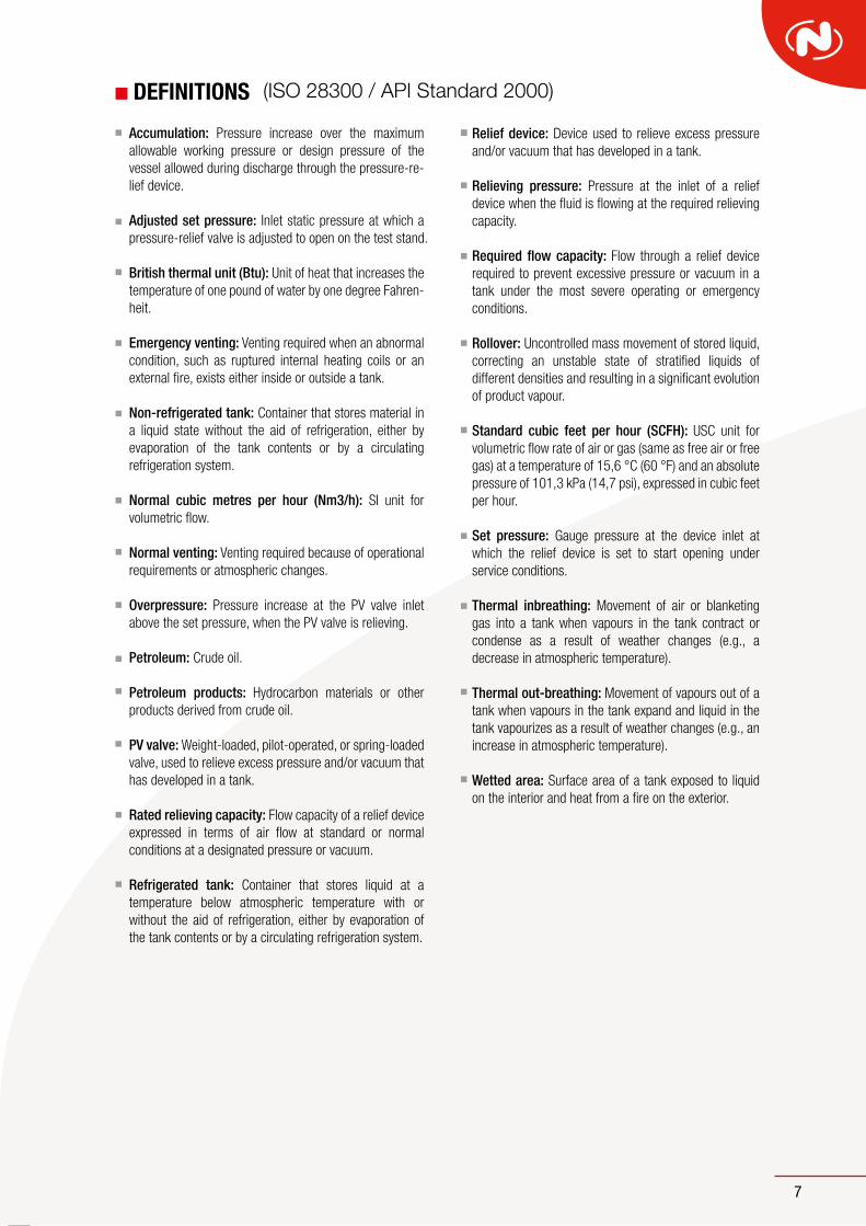
DEFINITIONS (ISO 28300 / API Standard 2000)
Accumulation: Pressure increase over the maximum allowable working pressure or design pressure of the vessel allowed during discharge through the pressure-re-lief device.
Adjusted set pressure: Inlet static pressure at which a pressure-relief valve is adjusted to open on the test stand.
British thermal unit (Btu): Unit of heat that increases the temperature of one pound of water by one degree Fahren-
heit.
Emergency venting: Venting required when an abnormal
condition, such as ruptured internal heating coils or an external fire, exists either inside or outside a tank.
Non-refrigerated tank: Container that stores material in a liquid state without the aid of refrigeration, either by
evaporation of the tank contents or by a circulating refrigeration system.
Normal cubic metres per hour (Nm3/h): SI unit for volumetric flow.
Normal venting: Venting required because of operational requirements or atmospheric changes.
Overpressure: Pressure increase at the PV valve inlet above the set pressure, when the PV valve is relieving.
Petroleum: Crude oil.
Petroleum products: Hydrocarbon materials or other products derived from crude oil.
PV valve: Weight-loaded, pilot-operated, or spring-loaded valve, used to relieve excess pressure and/or vacuum that has developed in a tank.
Rated relieving capacity: Flow capacity of a relief device expressed in terms of air flow at standard or normal conditions at a designated pressure or vacuum.
Refrigerated tank: Container that stores liquid at a temperature below atmospheric temperature with or without the aid of refrigeration, either by evaporation of the tank contents or by a circulating refrigeration system.
Relief device: Device used to relieve excess pressure and/or vacuum that has developed in a tank.
Relieving pressure: Pressure at the inlet of a relief device when the fluid is flowing at the required relieving capacity.
Required flow capacity: Flow through a relief device required to prevent excessive pressure or vacuum in a
tank under the most severe operating or emergency conditions.
Rollover: Uncontrolled mass movement of stored liquid, correcting an unstable state of stratified liquids of different densities and resulting in a significant evolution of product vapour.
Standard cubic feet per hour (SCFH): USC unit for
volumetric flow rate of air or gas (same as free air or free gas) at a temperature of 15,6 °C (60 °F) and an absolute pressure of 101,3 kPa (14,7 psi), expressed in cubic feet per hour.
Set pressure: Gauge pressure at the device inlet at which the relief device is set to start opening under service conditions.
Thermal inbreathing: Movement of air or blanketing gas into a tank when vapours in the tank contract or condense as a result of weather changes (e.g., a decrease in atmospheric temperature).
Thermal out-breathing: Movement of vapours out of a tank when vapours in the tank expand and liquid in the tank vapourizes as a result of weather changes (e.g., an increase in atmospheric temperature).
Wetted area: Surface area of a tank exposed to liquid on the interior and heat from a fire on the exterior.

Making safety since 1976
EMERGENCY VALVE
BREATHER VALVE
SAFETYVALVE
SAFETYVALVE
SAFETYVALVE
SAFETYVALVE
SAFETYVALVE
MOD-2000 MOD-5000 MOD-5900MOD-3400 MOD-5500 MOD-3-51 MOD-6400
C/ Compositor Vivaldi, 2-8, Pol. Ind Can Jardí08191 Rubí (Barcelona) - SpainTel.: +34 936 995 [email protected]
www.valvulasnacional.com