Emergency Lighting Device Notlichtversorgungsgerät CLS 24 ... · The CLS 24 local INOTEC emergency...
52
Sicherheitstechnik GmbH Mounting- and Operating Instructions Emergency Lighting Device CLS 24/SV CLS Power Montage- und Betriebsanleitung Notlichtversorgungsgerät CLS 24/SV CLS Power
Transcript of Emergency Lighting Device Notlichtversorgungsgerät CLS 24 ... · The CLS 24 local INOTEC emergency...
Sicherheitstechnik GmbH
Mounting- and Operating Instructions
Emergency Lighting Device
CLS 24/SVCLS Power
Montage- und Betriebsanleitung
Notlichtversorgungsgerät
CLS 24/SVCLS Power

�
CLS 24/SV Montage- und Betriebsanleitung CLS 24/SV Mounting and Operating Instructions
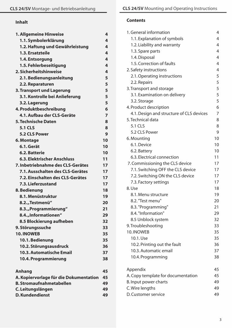
Inhalt
1. Allgemeine Hinweise 4 1.1. Symbolerklärung 4 1.2. Haftung und Gewährleistung 4 1.3. Ersatzteile 4 1.4. Entsorgung 4 1.5. Fehlerbeseitigung 42. Sicherheitshinweise 4 2.1. Bedienungsanleitung 5 2.2. Reparaturen 53. Transport und Lagerung 5 3.1. Kontrolle bei Anlieferung 5 3.2. Lagerung 54. Produktbeschreibung 6 4.1. Aufbau der CLS-Geräte 75. Technische Daten 8 5.1 CLS 8 5.2 CLS Power 96. Montage 10 6.1. Gerät 10 6.2. Batterie 10 6.3. Elektrischer Anschluss 117. Inbetriebnahme des CLS-Gerätes 17 7.1. Ausschalten des CLS-Gerätes 17 7.2. Einschalten des CLS-Gerätes 17 7.3. Lieferzustand 178. Bedienung 18 8.1. Menüstruktur 19 8.2. „Testmenü“ 20 8.3. „Programmierung“ 21 8.4. „Informationen“ 29 8.5 Blockierung aufheben 329. Störungssuche 3310. INOWEB 35 10.1. Bedienung 35 10.2. Störungsausdruck 36 10.3. Automatische Email 37 10.4. Programmierung 38
Anhang 45A. Kopiervorlage für die Dokumentation 45B. Stromaufnahmetabellen 49C. Leitungslängen 49D. Kundendienst 49
Contents
1. General information 4 1.1. Explanation of symbols 4 1.2. Liability and warranty 4 1.�. Spare parts 4 1.4. Disposal 4 1.5. Correction of faults 42. Safety instructions 4 2.1. Operating instructions 5 2.2. Repairs 5�. Transport and storage 5 �.1. Examination on delivery 5 �.2. Storage 54. Product description 6 4.1. Design and structure of CLS devices 75. Technical data 8 5.1 CLS 8 5.2 CLS Power 96. Mounting 10 6.1. Device 10 6.2. Battery 10 6.�. Electrical connection 11 7. Commissioning the CLS device 17 7.1. Switching OFF the CLS device 17 7.2. Switching ON the CLS device 17 7.�. Factory settings 178. Use 18 8.1. Menu structure 19 8.2. "Test menu" 20 8.�. "Programming" 21 8.4. "Information" 29 8.5 Unblock system �29. Troubleshooting ��10. INOWEB �5 10.1. Use �5 10.2. Printing out the fault �6 10.�. Automatic email �7 10.4. Programming �8
Appendix 45A. Copy template for documentation 45B. Input power charts 49C. Wire lengths 49D. Customer service 49
4
CLS 24/SV Montage- und Betriebsanleitung CLS 24/SV Mounting and Operating Instructions
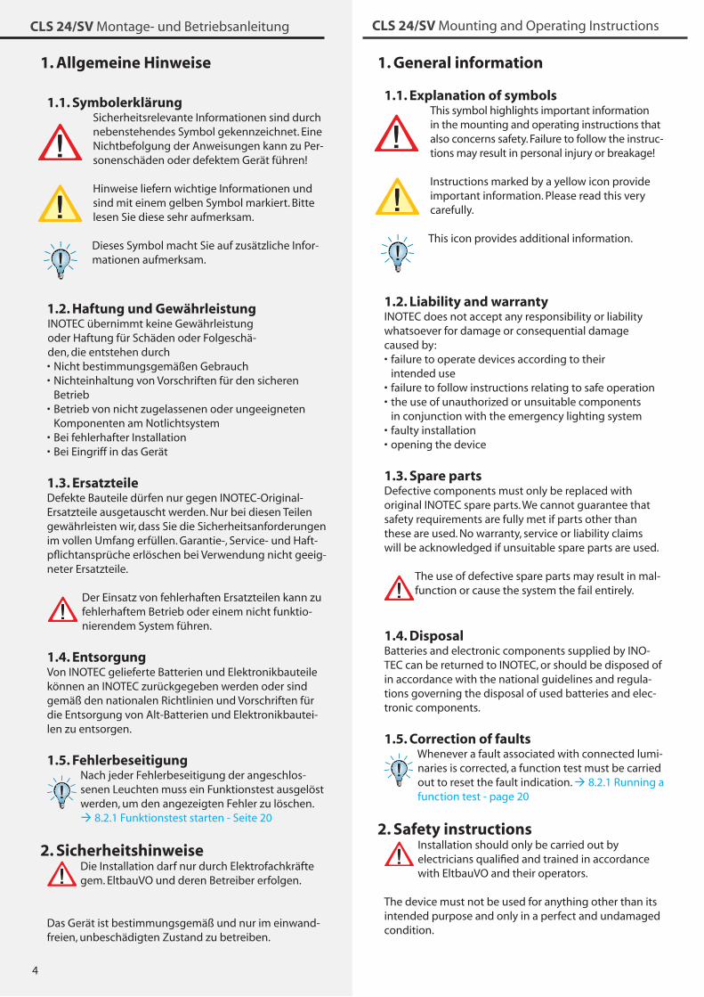
1. General information
1.1. Explanation of symbols This symbol highlights important information in the mounting and operating instructions that also concerns safety. Failure to follow the instruc-tions may result in personal injury or breakage! Instructions marked by a yellow icon provide important information. Please read this very carefully. This icon provides additional information.
1.2. Liability and warrantyINOTEC does not accept any responsibility or liability whatsoever for damage or consequential damage caused by:
failure to operate devices according to their intended usefailure to follow instructions relating to safe operationthe use of unauthorized or unsuitable components in conjunction with the emergency lighting systemfaulty installation opening the device
1.3. Spare partsDefective components must only be replaced with original INOTEC spare parts. We cannot guarantee that safety requirements are fully met if parts other than these are used. No warranty, service or liability claims will be acknowledged if unsuitable spare parts are used.
The use of defective spare parts may result in mal-function or cause the system the fail entirely.
1.4. DisposalBatteries and electronic components supplied by INO-TEC can be returned to INOTEC, or should be disposed of in accordance with the national guidelines and regula-tions governing the disposal of used batteries and elec-tronic components.
1.5. Correction of faultsWhenever a fault associated with connected lumi-naries is corrected, a function test must be carried out to reset the fault indication. 8.2.1 Running a function test - page 20
2. Safety instructionsInstallation should only be carried out by electricians qualified and trained in accordance with EltbauVO and their operators.
The device must not be used for anything other than its intended purpose and only in a perfect and undamaged condition.
•
••
••
1. Allgemeine Hinweise
1.1. Symbolerklärung Sicherheitsrelevante Informationen sind durch nebenstehendes Symbol gekennzeichnet. Eine Nichtbefolgung der Anweisungen kann zu Per-sonenschäden oder defektem Gerät führen! Hinweise liefern wichtige Informationen und sind mit einem gelben Symbol markiert. Bitte lesen Sie diese sehr aufmerksam. Dieses Symbol macht Sie auf zusätzliche Infor-mationen aufmerksam.
1.2. Haftung und GewährleistungINOTEC übernimmt keine Gewährleistung oder Haftung für Schäden oder Folgeschä-den, die entstehen durch
Nicht bestimmungsgemäßen GebrauchNichteinhaltung von Vorschriften für den sicheren BetriebBetrieb von nicht zugelassenen oder ungeeigneten Komponenten am NotlichtsystemBei fehlerhafter Installation Bei Eingriff in das Gerät
1.3. ErsatzteileDefekte Bauteile dürfen nur gegen INOTEC-Original-Ersatzteile ausgetauscht werden. Nur bei diesen Teilen gewährleisten wir, dass Sie die Sicherheitsanforderungen im vollen Umfang erfüllen. Garantie-, Service- und Haft-pflichtansprüche erlöschen bei Verwendung nicht geeig-neter Ersatzteile.
Der Einsatz von fehlerhaften Ersatzteilen kann zu fehlerhaftem Betrieb oder einem nicht funktio-nierendem System führen.
1.4. EntsorgungVon INOTEC gelieferte Batterien und Elektronikbauteile können an INOTEC zurückgegeben werden oder sind gemäß den nationalen Richtlinien und Vorschriften für die Entsorgung von Alt-Batterien und Elektronikbautei-len zu entsorgen.
1.5. Fehlerbeseitigung Nach jeder Fehlerbeseitigung der angeschlos-senen Leuchten muss ein Funktionstest ausgelöst werden, um den angezeigten Fehler zu löschen. 8.2.1 Funktionstest starten - Seite 20
2. SicherheitshinweiseDie Installation darf nur durch Elektrofachkräfte gem. EltbauVO und deren Betreiber erfolgen.
Das Gerät ist bestimmungsgemäß und nur im einwand- freien, unbeschädigten Zustand zu betreiben.
••
•
••
5
CLS 24/SV Montage- und Betriebsanleitung CLS 24/SV Mounting and Operating Instructions
When installing and operating this device, please follow your national safety and accident prevention regulations at all times.
Before carrying out any work on the device, in particular when replacing components, always disconnect the system from the power source (mains and battery). 7. Commissioning - page 17
2.1. Operating instructionsAlways read the mounting and operating instruc-tions before installing and commissioning the device. These instructions contain important
information on the safety, use and maintenance of the device, and will protect you and prevent damage to the system.
2.2. RepairsAny repairs which need to be carried out or which involve opening the device must ONLY be carried out by personnel authorized to do so by INOTEC.
3. Transport and storage
3.1. Examination on deliveryPlease examine the device carefully at point of receipt to ensure complete delivery and that no external dam-age exists. Please inform the carrier immediately if there are any signs of damage — we regret that we are unable to acknowledge complaints submitted after this point.
3.2. StorageUntil assembly, please observe the following regarding storage of the device:
Do not store in the open airDo store in a dry, dust-free environment
The following applies to batteries that have already been fitted:
Batteries must not be stored for more than � months without being chargedIf the mains supply is interrupted for an extended period of time, the battery circuit must be disconnected by removing the battery fuse in accordance with the operating instructions – 7. Commissioning - page 17 Charge the batteries for at least 24 hours before carrying out the initial function test
••
•
•
•
Für die Installation und den Betrieb dieses Gerätes sind die nationalen Sicherheits- und Unfallverhütungsvor-schriften zu beachten.
Vor Arbeiten an dem Gerät, insbesondere beim Aus-tausch von Baugruppen, ist die Anlage spannungsfrei zu schalten (Netz- und Batteriespannung)! 7. Inbetrieb-nahme - Seite 17
2.1. BedienungsanleitungLesen Sie vor der Montage- und Inbetriebnahme die Montage- und Betriebsanleitung. Sie gibt wichtige Informationen für die Sicherheit, den
Gebrauch und die Wartung des Gerätes. Dadurch schüt-zen Sie sich und verhindern Schäden am Gerät.
2.2. ReparaturenEventuelle Reparaturen oder Eingriffe dürfen ausschließ-lich durch INOTEC autorisierte Personen vorgenommen werden.
3. Transport und Lagerung
3.1. Kontrolle bei AnlieferungÜberprüfen Sie das Gerät bei Anlieferung unverzüglich auf Vollständigkeit und äußere Beschädigungen. Mel-den Sie dem Spediteur offensichtliche Beschädigungen sofort, da wir spätere Reklamationen nicht anerkennen.
3.2. LagerungDas Gerät ist bis zur Montage wie folgt zu lagern:
Nicht im Freien aufbewahrenTrocken und staubfrei lagern
Für die eingebauten Batterien gilt:Batterien dürfen max. � Monate ohne Ladung gelagert werdenBei längerer Unterbrechung der Netzversorgung muss der Batteriekreis durch entfernen der Batteriesicherung gemäß Betriebsanleitung freigeschaltet werden 7. Inbetriebnahme - Seite 17Vor der ersten Funktionsprüfung sind die Batterien min. 24 Stunden zu laden
••
•
•
•

6
CLS 24/SV Montage- und Betriebsanleitung CLS 24/SV Mounting and Operating Instructions
4. Product description
The CLS 24 local INOTEC emergency lighting system is a protection class I supply device for using and monitor-ing up to 80 safety and emergency exit luminaries. You can operate up to 20 luminaries with different switching modes for each outgoing circuit.
The CLS system includes:Battery for 1 h, � h or 8 hours of emergency lighting4 outgoing circuits designed for up to 20 luminaries with a maximum connected output of max. �A per circuitController with 4-row display for status information4-channel light sequence switchingIntegrated logbookOptional network module INOWEB
The luminaries are supplied via a dual conductor sup-ply lead with 24V low voltage protection and can be programmed using the device controller. Programming involves assigning the luminaries unique address with a logical link to a circuit address.
The programmable controller has 4 status LEDs and a 4-row alphanumeric display to indicate the current device and luminaire status. With the PS/2 interface built-in as standard, you can use a regular keyboard to enter textual information concerning each luminaire.
You can conduct manual tests to check the system at any time, or have the system conduct automatic tests at any programmed time. Details of the test results are saved in the integrated logbook for you to view when you prefer (approx. 1000 entries).
There are 4 voltfree contacts on the external error mes-sage/status display. One of these contacts can be pro-grammed at will.
An optional network module can be used to call up the status anywhere on the network via a web browser. Set any password you like to protect access to the HTML pages.
••
••••
4. Produktbeschreibung
Die dezentrale INOTEC Notlichtanlage CLS 24 ist ein Ver-sorgungsgerät in Schutzklasse I für den Betrieb und die Überwachung von bis zu 80 Sicherheits- und Rettungs-zeichenleuchten. Je Abgang können bis zu 20 Leuchten in unterschiedlichen Schaltungsarten betrieben werden.
Das CLS System beinhaltet:Batterie für 1 Std., � Std. oder 8 Std. Notlichtbetrieb4 Stromkreisabgänge geeignet für bis zu 20 Leuchten mit einer maximalen Anschlussleistung von max. �A je StromkreisSteuerteil mit vierzeiligem Display für Statusinformationen4-kanaliger LichtschalterabfrageIntegriertes PrüfbuchOptionales Netzwerkmodul INOWEB
Die Leuchten werden über eine zweiadrige Versor-gungsleitung mit 24V-Schutzkleinspannung versorgt und können über das Gerätesteuerteil programmiert werden. Dabei wird der eindeutigen Leuchtenadresse eine logische Verknüpfung mit einer Stromkreisadresse zugewiesen.
Das frei programmierbare Steuerteil hat vier Status-LED und ein vierzeiliges alphanummerisches Display zur Anzeige des jeweiligen Geräte- und Leuchtenzustan-des. Über die serienmäßig integrierte PS/2-Schnittstelle können Textinformation zu den einzelnen Leuchten mit einer handelsüblichen Tastatur erfasst werden.
Jederzeit können manuelle Tests zur Überprüfung ausge-löst werden. Ebenso sind automatische Tests zu frei pro-grammierbaren Zeitpunkten möglich. Die Testergebnisse werden im integrierten Prüfbuch detailliert gespeichert und sind jederzeit abrufbar (ca. 1.000 Einträge).
Vier potentialfreie Kontakte zur externen Fehlermel-dung/Statusanzeige sind vorhanden. Einer dieser Kon-takte ist frei programmierbar.
Über ein optionales Netzwerkmodul kann der Zustand überall im Netzwerk per Webbrowser abgerufen werden. Der Zugriff auf die HTML-Seiten ist über ein frei wähl-bares Passwort zu schützen.
••
•
•••
7
CLS 24/SV Montage- und Betriebsanleitung CLS 24/SV Mounting and Operating Instructions
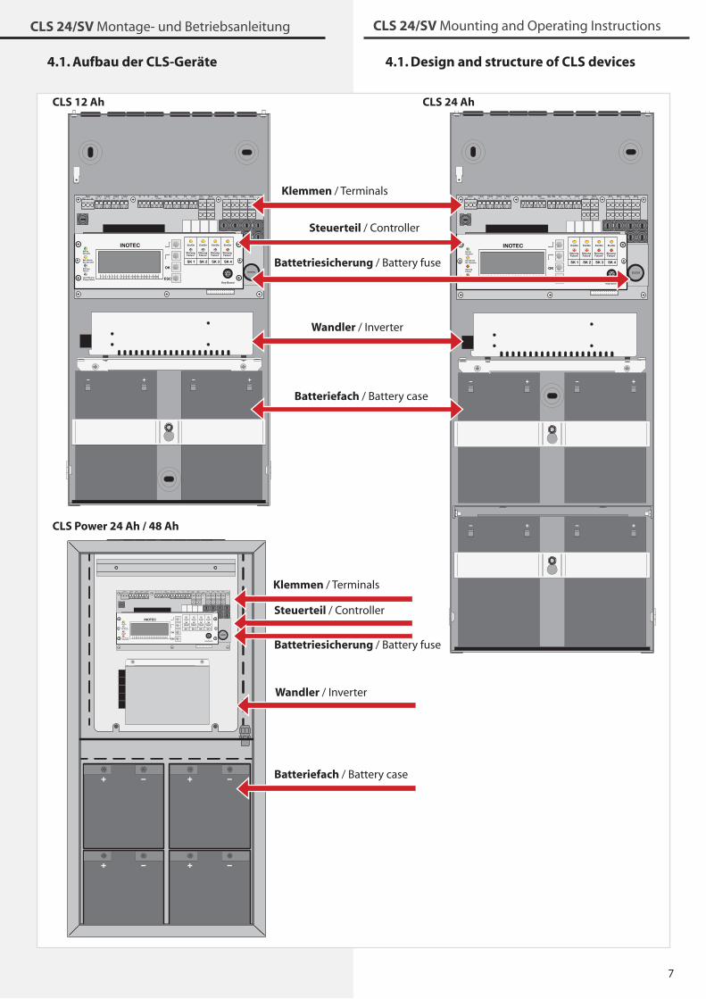
4.1. Aufbau der CLS-Geräte 4.1. Design and structure of CLS devices
NetzN LLSA1
N LLSA2
N LLSA3
N LLSA4
LPE NR T G IBa IBpIBp
+24V
T FSSL+– +–
+24V+–
Opt.Stoer
Betr.Bat.-B.
SK1- +- +SK2- +- +
SK3- +- +SK4- +- +
INOTEC
1 2 3 4 5 6 7 8 9 10 11 12 13 14 15 16 17 18 19 20
SK 1 SK 2 SK 3 SK 4
Ein/On
StörungFailure
Ein/On
StörungFailure
Ein/On
StörungFailure
Ein/On
StörungFailure
Lade StörungCharge failure
StörungFailure
Batt.-BetriebBat.-Operation
BetriebOperation
OK
ESC
Klemmen / Terminals
Steuerteil / Controller
Battetriesicherung / Battery fuse
Wandler / Inverter
Batteriefach / Battery case
CLS 12 Ah CLS 24 Ah
CLS Power 24 Ah / 48 Ah
8
CLS 24/SV Montage- und Betriebsanleitung CLS 24/SV Mounting and Operating Instructions
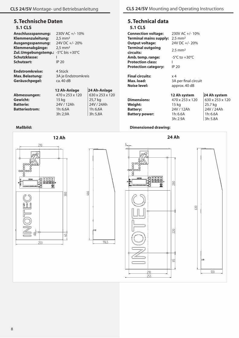
5. Technical data5.1 CLS
Connection voltage: 2�0V AC +/- 10%Terminal mains supply: 2.5 mm²Output voltage: 24V DC +/- 20%Terminal outgoing circuits:
2.5 mm²
Amb. temp. range: -5°C to +�0°CProtection class: IProtection category: IP 20
Final circuits: x 4Max. load: �A per final circuitNoise level: approx. 40 dB
12 Ah system 24 Ah systemDimensions: 470 x 25� x 120 6�0 x 25� x 120Weight: 15 kg 25.7 kgBattery: 24V / 12Ah 24V / 24AhBattery power: 1h: 6.6A
�h: 2.9A1h: 6.6A�h: 5.8A
Dimensioned drawing:
5. Technische Daten5.1 CLS
Anschlussspannung: 2�0V AC +/- 10%Klemmenzuleitung: 2,5 mm²Ausgangsspannung: 24V DC +/- 20%Klemmenabgänge: 2,5 mm²Zul. Umgebungstemp.: -5°C bis +�0°CSchutzklasse: ISchutzart: IP 20
Endstromkreise: 4 StückMax. Belastung: �A je EndstromkreisGeräuschpegel: ca. 40 dB
12 Ah-Anlage 24 Ah-AnlageAbmessungen: 470 x 25� x 120 6�0 x 25� x 120Gewicht: 15 kg 25,7 kgBatterie: 24V / 12Ah 24V / 24AhBatteriestrom: 1h: 6,6A
�h: 2,9A1h: 6,6A�h: 5,8A
Maßbild:
253
630
120
8522
028
0
210
6ø
116,5253
466
380
40
210
ø6
12 Ah 24 Ah
9
CLS 24/SV Montage- und Betriebsanleitung CLS 24/SV Mounting and Operating Instructions
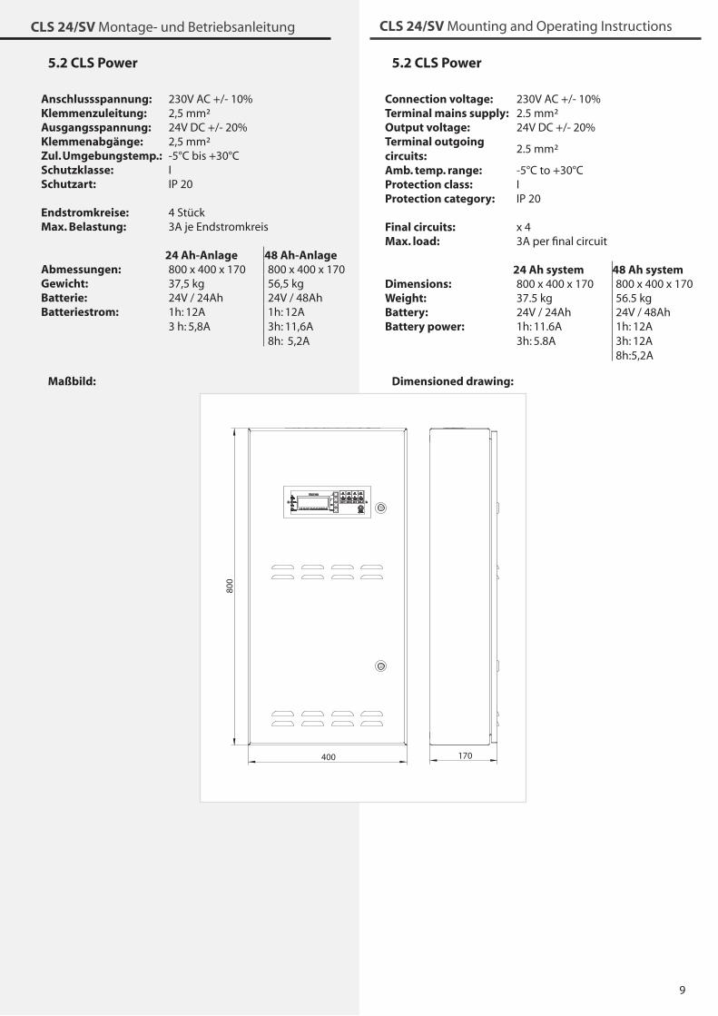
5.2 CLS Power
Connection voltage: 2�0V AC +/- 10%Terminal mains supply: 2.5 mm²Output voltage: 24V DC +/- 20%Terminal outgoing circuits:
2.5 mm²
Amb. temp. range: -5°C to +�0°CProtection class: IProtection category: IP 20
Final circuits: x 4Max. load: �A per final circuit
24 Ah system 48 Ah systemDimensions: 800 x 400 x 170 800 x 400 x 170Weight: �7.5 kg 56.5 kgBattery: 24V / 24Ah 24V / 48AhBattery power: 1h: 11.6A
�h: 5.8A1h: 12A�h: 12A8h:5,2A
Dimensioned drawing:
5.2 CLS Power
Anschlussspannung: 2�0V AC +/- 10%Klemmenzuleitung: 2,5 mm²Ausgangsspannung: 24V DC +/- 20%Klemmenabgänge: 2,5 mm²Zul. Umgebungstemp.: -5°C bis +�0°CSchutzklasse: ISchutzart: IP 20
Endstromkreise: 4 StückMax. Belastung: �A je Endstromkreis
24 Ah-Anlage 48 Ah-AnlageAbmessungen: 800 x 400 x 170 800 x 400 x 170Gewicht: �7,5 kg 56,5 kgBatterie: 24V / 24Ah 24V / 48AhBatteriestrom: 1h: 12A
� h: 5,8A1h: 12A�h: 11,6A8h: 5,2A
Maßbild:
800
400 170
10
CLS 24/SV Montage- und Betriebsanleitung CLS 24/SV Mounting and Operating Instructions
6. Mounting
When mounting the device, make sure that the supporting wall is strong enough to support the load and that suitable mounting materials (dowels) are used.
The emergency lighting device CLS is supplied with bat-teries installed.
The emergency lighting device CLS Power is supplied without installed batteries.
6.1. Device
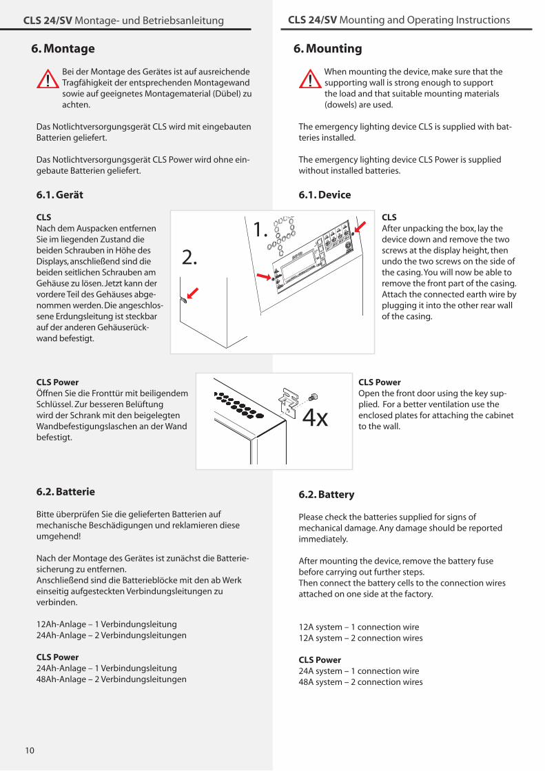
CLS After unpacking the box, lay the device down and remove the two screws at the display height, then undo the two screws on the side of the casing. You will now be able to remove the front part of the casing. Attach the connected earth wire by plugging it into the other rear wall of the casing.
CLS Power Open the front door using the key sup-plied. For a better ventilation use the enclosed plates for attaching the cabinet to the wall.
6.2. Battery
Please check the batteries supplied for signs of mechanical damage. Any damage should be reported immediately.
After mounting the device, remove the battery fuse before carrying out further steps.Then connect the battery cells to the connection wires attached on one side at the factory.
12A system – 1 connection wire12A system – 2 connection wires
CLS Power 24A system – 1 connection wire48A system – 2 connection wires
6. Montage
Bei der Montage des Gerätes ist auf ausreichende Tragfähigkeit der entsprechenden Montagewand sowie auf geeignetes Montagematerial (Dübel) zu achten.
Das Notlichtversorgungsgerät CLS wird mit eingebauten Batterien geliefert.
Das Notlichtversorgungsgerät CLS Power wird ohne ein-gebaute Batterien geliefert.
6.1. Gerät
CLSNach dem Auspacken entfernen Sie im liegenden Zustand die beiden Schrauben in Höhe des Displays, anschließend sind die beiden seitlichen Schrauben am Gehäuse zu lösen. Jetzt kann der vordere Teil des Gehäuses abge-nommen werden. Die angeschlos-sene Erdungsleitung ist steckbar auf der anderen Gehäuserück-wand befestigt.
CLS Power Öffnen Sie die Fronttür mit beiligendem Schlüssel. Zur besseren Belüftung wird der Schrank mit den beigelegten Wandbefestigungslaschen an der Wand befestigt.
6.2. Batterie
Bitte überprüfen Sie die gelieferten Batterien auf mechanische Beschädigungen und reklamieren diese umgehend!
Nach der Montage des Gerätes ist zunächst die Batterie-sicherung zu entfernen.Anschließend sind die Batterieblöcke mit den ab Werk einseitig aufgesteckten Verbindungsleitungen zu verbinden.
12Ah-Anlage – 1 Verbindungsleitung24Ah-Anlage – 2 Verbindungsleitungen
CLS Power 24Ah-Anlage – 1 Verbindungsleitung48Ah-Anlage – 2 Verbindungsleitungen
2.1.
2.1.
4x4x
11
CLS 24/SV Montage- und Betriebsanleitung CLS 24/SV Mounting and Operating Instructions
6.3. Electrical connection.
6.3.1. Mains connection
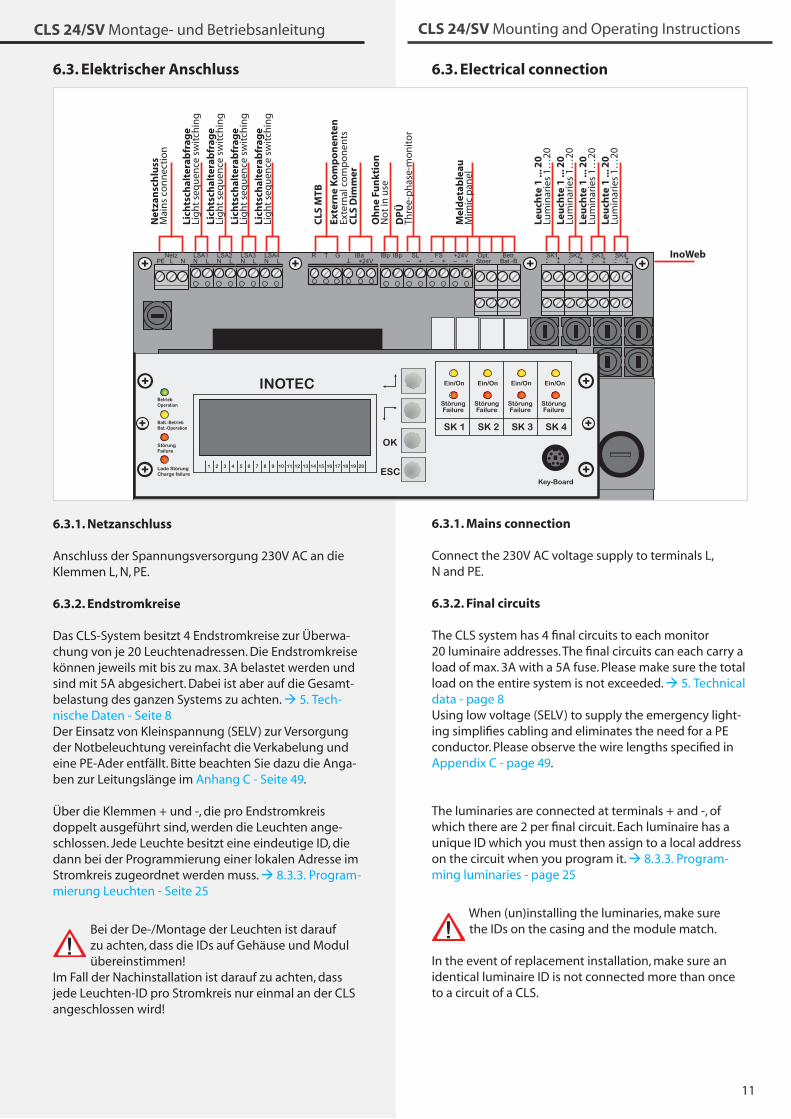
Connect the 2�0V AC voltage supply to terminals L, N and PE.
6.3.2. Final circuits
The CLS system has 4 final circuits to each monitor 20 luminaire addresses. The final circuits can each carry a load of max. �A with a 5A fuse. Please make sure the total load on the entire system is not exceeded. 5. Technical data - page 8 Using low voltage (SELV) to supply the emergency light-ing simplifies cabling and eliminates the need for a PE conductor. Please observe the wire lengths specified in Appendix C - page 49.
The luminaries are connected at terminals + and -, of which there are 2 per final circuit. Each luminaire has a unique ID which you must then assign to a local address on the circuit when you program it. 8.�.�. Program-ming luminaries - page 25
When (un)installing the luminaries, make sure the IDs on the casing and the module match.
In the event of replacement installation, make sure an identical luminaire ID is not connected more than once to a circuit of a CLS.
6.3. Elektrischer Anschluss
NetzN LLSA1
N LLSA2
N LLSA3
N LLSA4
LPE NR T G IBa IBpIBp
+24V
T FSSL+– +–
+24V+–
Opt.Stoer
Betr.Bat.-B.
SK1- +- +SK2- +- +
SK3- +- +SK4- +- +
INOTEC
1 2 3 4 5 6 7 8 9 10 11 12 13 14 15 16 17 18 19 20
SK 1 SK 2 SK 3 SK 4
Ein/On
StörungFailure
Ein/On
StörungFailure
Ein/On
StörungFailure
Ein/On
StörungFailure
Lade StörungCharge failure
StörungFailure
Batt.-BetriebBat.-Operation
BetriebOperation
OK
ESC
Net
zan
sch
luss
Mai
ns
con
nec
tio
n
Lich
tsch
alte
rab
frag
eLi
gh
t se
qu
ence
sw
itch
ing
Lich
tsch
alte
rab
frag
eLi
gh
t se
qu
ence
sw
itch
ing
Lich
tsch
alte
rab
frag
eLi
gh
t se
qu
ence
sw
itch
ing
Lich
tsch
alte
rab
frag
eLi
gh
t se
qu
ence
sw
itch
ing
CLS
MTB
Oh
ne
Fun
ktio
nN
ot
in u
se
DP
ÜTh
ree-
ph
ase-
mo
nit
or
Mel
det
able
auM
imic
pan
el
Leu
chte
1 ..
. 20
Lum
inar
ies
1…20
Leu
chte
1 ..
. 20
Lum
inar
ies
1…20
Leu
chte
1 ..
. 20
Lum
inar
ies
1…20
Leu
chte
1 ..
. 20
Lum
inar
ies
1…20
InoWeb
Exte
rne
Ko
mp
on
ente
nEx
tern
alco
mp
on
ents
CLS
Dim
mer
6.3.1. Netzanschluss
Anschluss der Spannungsversorgung 2�0V AC an die Klemmen L, N, PE.
6.3.2. Endstromkreise
Das CLS-System besitzt 4 Endstromkreise zur Überwa-chung von je 20 Leuchtenadressen. Die Endstromkreise können jeweils mit bis zu max. �A belastet werden und sind mit 5A abgesichert. Dabei ist aber auf die Gesamt-belastung des ganzen Systems zu achten. 5. Tech-nische Daten - Seite 8 Der Einsatz von Kleinspannung (SELV) zur Versorgung der Notbeleuchtung vereinfacht die Verkabelung und eine PE-Ader entfällt. Bitte beachten Sie dazu die Anga-ben zur Leitungslänge im Anhang C - Seite 49.
Über die Klemmen + und -, die pro Endstromkreis doppelt ausgeführt sind, werden die Leuchten ange-schlossen. Jede Leuchte besitzt eine eindeutige ID, die dann bei der Programmierung einer lokalen Adresse im Stromkreis zugeordnet werden muss. 8.�.�. Program-mierung Leuchten - Seite 25
Bei der De-/Montage der Leuchten ist darauf zu achten, dass die IDs auf Gehäuse und Modul übereinstimmen!
Im Fall der Nachinstallation ist darauf zu achten, dass jede Leuchten-ID pro Stromkreis nur einmal an der CLS angeschlossen wird!
12
CLS 24/SV Montage- und Betriebsanleitung CLS 24/SV Mounting and Operating Instructions
Connection example L-JET
6.3.3. Light sequence switching
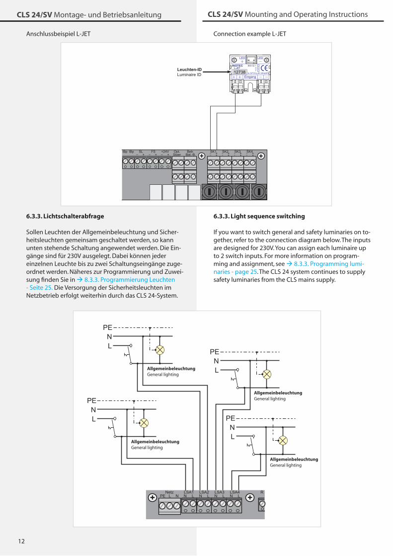
If you want to switch general and safety luminaries on to-gether, refer to the connection diagram below. The inputs are designed for 2�0V. You can assign each luminaire up to 2 switch inputs. For more information on program-ming and assignment, see 8.�.�. Programming lumi-naries - page 25. The CLS 24 system continues to supply safety luminaries from the CLS mains supply.
Anschlussbeispiel L-JET
6.3.3. Lichtschalterabfrage
Sollen Leuchten der Allgemeinbeleuchtung und Sicher-heitsleuchten gemeinsam geschaltet werden, so kann unten stehende Schaltung angewendet werden. Die Ein-gänge sind für 2�0V ausgelegt. Dabei können jeder einzelnen Leuchte bis zu zwei Schaltungseingänge zuge-ordnet werden. Näheres zur Programmierung und Zuwei-sung finden Sie in 8.�.�. Programmierung Leuchten - Seite 25. Die Versorgung der Sicherheitsleuchten im Netzbetrieb erfolgt weiterhin durch das CLS 24-System.
NetzN LLSA1
N LLSA2
N LLSA3
N LLSA4
LPE NR
NPE
LPENL
AllgemeinbeleuchtungGeneral lighting
PENL
AllgemeinbeleuchtungGeneral lighting
PENL
AllgemeinbeleuchtungGeneral lighting
PENL
AllgemeinbeleuchtungGeneral lighting
INOTECL-JET
860 02 137
ta: 50°C/Un:DC 24V±20%
Eingang
IBpIBp FSSL+– +–
+24V+–
Opt.Stoer
Betr.Bat.-B.
SK1- +- +SK2- +- +
SK3- +- +SK4- +- +
12738Leuchten-IDLuminaire ID
1�
CLS 24/SV Montage- und Betriebsanleitung CLS 24/SV Mounting and Operating Instructions
6.3.4. 24V current loop
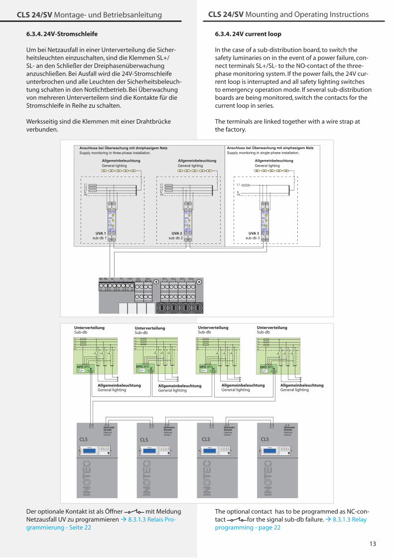
In the case of a sub-distribution board, to switch the safety luminaries on in the event of a power failure, con-nect terminals SL+/SL- to the NO-contact of the three-phase monitoring system. If the power fails, the 24V cur-rent loop is interrupted and all safety lighting switches to emergency operation mode. If several sub-distribution boards are being monitored, switch the contacts for the current loop in series.
The terminals are linked together with a wire strap at the factory.
The optional contact has to be programmed as NC-con-tact for the signal sub-db failure. 8.�.1.� Relay programming - page 22
6.3.4. 24V-Stromschleife
Um bei Netzausfall in einer Unterverteilung die Sicher-heitsleuchten einzuschalten, sind die Klemmen SL+/SL- an den Schließer der Dreiphasenüberwachung anzuschließen. Bei Ausfall wird die 24V-Stromschleife unterbrochen und alle Leuchten der Sicherheitsbeleuch-tung schalten in den Notlichtbetrieb. Bei Überwachung von mehreren Unterverteilern sind die Kontakte für die Stromschleife in Reihe zu schalten.
Werksseitig sind die Klemmen mit einer Drahtbrücke verbunden.
Der optionale Kontakt ist als Öffner mit Meldung Netzausfall UV zu programmieren 8.�.1.� Relais Pro-grammierung - Seite 22
Anschluss bei Überwachung mit einphasigem NetzSupply monitoring in single-phase installation.
L1L2L3NPE
sub db 1
L1L2L3NPE
sub db 2
L1
NPE
sub db 3UVA 1 UVA 2 UVA 3
L3 L1L2 N
L1DPÜ
L2gem.VDE0108
L3
1214 11
INOTEC
L3 L1L2 N
L1DPÜ
L2gem.VDE0108
L3
1214 11
INOTEC
L3 L1L2 N
L1DPÜ
L2gem.VDE0108
L3
1214 11
INOTEC
Allgemeinbeleuchtung Allgemeinbeleuchtung AllgemeinbeleuchtungGeneral lighting General lighting General lighting
Anschluss bei Überwachung mit dreiphasigem NetzSupply monitoring in three-phase installation.
IBpIBp FSSL+– +–
+24V+–
Opt.Stoer
Betr.Bat.-B.
SK1- +- +SK2- +- +
SK3- +- +SK4- +- +
Allgemeinbeleuchtung Allgemeinbeleuchtung AllgemeinbeleuchtungGeneral lighting General lighting General lighting
AllgemeinbeleuchtungGeneral lighting
Unterverteilung Unterverteilung UnterverteilungSub-db Sub-db Sub-db
UnterverteilungSub-db
INOTEC
1 2 3 4 5 6 7 8 9 10 11 12 13 14 15 16 17 18 19 20
SK 1 SK 2 SK 3 SK 4
Ein/On
StörungFailure
Ein/On
StörungFailure
Ein/On
StörungFailure
Ein/On
StörungFailure
Lade StörungCharge failure
StörungFailure
Batt.-BetriebBat.-Operation
BetriebOperation
OK
ESC
S+ S- OptionalerKontakt
INOTEC
1 2 3 4 5 6 7 8 9 10 11 12 13 14 15 16 17 18 19 20
SK 1 SK 2 SK 3 SK 4
Ein/On
StörungFailure
Ein/On
StörungFailure
Ein/On
StörungFailure
Ein/On
StörungFailure
Lade StörungCharge failure
StörungFailure
Batt.-BetriebBat.-Operation
BetriebOperation
OK
ESC
S+ S- OptionalerKontakt
U<DPÜ
U<DPÜ
S+ S-
L1
L2
L3
N
PE
U<DPÜ
S+ S-
L1
L2
L3
N
PE
S+ S-
L1
L2
L3
N
PE
U<DPÜ3PO3PO 3PO 3PO
S+ S-
L1
L2
L3
N
PE
INOTEC
1 2 3 4 5 6 7 8 9 10 11 12 13 14 15 16 17 18 19 20
SK 1 SK 2 SK 3 SK 4
Ein/On
StörungFailure
Ein/On
StörungFailure
Ein/On
StörungFailure
Ein/On
StörungFailure
Lade StörungCharge failure
StörungFailure
Batt.-BetriebBat.-Operation
BetriebOperation
OK
ESC
S+ S- OptionalerKontakt
INOTEC
1 2 3 4 5 6 7 8 9 10 11 12 13 14 15 16 17 18 19 20
SK 1 SK 2 SK 3 SK 4
Ein/On
StörungFailure
Ein/On
StörungFailure
Ein/On
StörungFailure
Ein/On
StörungFailure
Lade StörungCharge failure
StörungFailure
Batt.-BetriebBat.-Operation
BetriebOperation
OK
ESC
S+ S- OptionalerKontakt
Optionalcontact
Optionalcontact
Optionalcontact
Optionalcontact
CLS CLS CLS CLS
14
CLS 24/SV Montage- und Betriebsanleitung CLS 24/SV Mounting and Operating Instructions
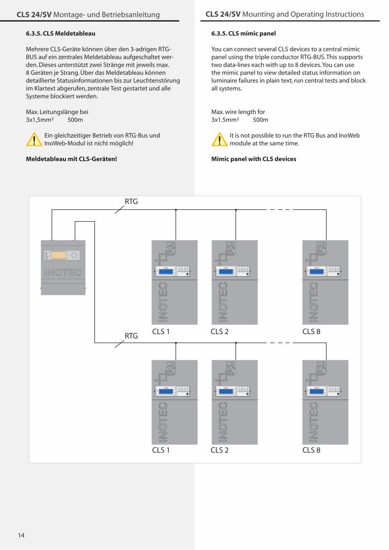
6.3.5. CLS mimic panel
You can connect several CLS devices to a central mimic panel using the triple conductor RTG-BUS. This supports two data-lines each with up to 8 devices. You can use the mimic panel to view detailed status information on luminaire failures in plain text, run central tests and block all systems.
Max. wire length for�x1.5mm² 500m
It is not possible to run the RTG Bus and InoWeb module at the same time.
Mimic panel with CLS devices
6.3.5. CLS Meldetableau
Mehrere CLS-Geräte können über den �-adrigen RTG-BUS auf ein zentrales Meldetableau aufgeschaltet wer-den. Dieses unterstützt zwei Stränge mit jeweils max. 8 Geräten je Strang. Über das Meldetableau können detaillierte Statusinformationen bis zur Leuchtenstörung im Klartext abgerufen, zentrale Test gestartet und alle Systeme blockiert werden.
Max. Leitungslänge bei�x1,5mm² 500m
Ein gleichzeitiger Betrieb von RTG-Bus und InoWeb-Modul ist nicht möglich!
Meldetableau mit CLS-Geräten!
StörungFailure
Batt.-BetriebBat.-Operation
BetriebOperation
CLS 1
RTG
CLS 2 CLS 8
CLS 1 CLS 2 CLS 8
RTG
INOTEC
1 2 3 4 5 6 7 8 9 10 11 12 13 14 15 16 17 18 19 20
SK 1 SK 2 SK 3 SK 4
Ein/On
StörungFailure
Ein/On
StörungFailure
Ein/On
StörungFailure
Ein/On
StörungFailure
Lade StörungCharge failure
StörungFailure
Batt.-BetriebBat.-Operation
BetriebOperation
OK
ESC
INOTEC
1 2 3 4 5 6 7 8 9 10 11 12 13 14 15 16 17 18 19 20
SK 1 SK 2 SK 3 SK 4
Ein/On
StörungFailure
Ein/On
StörungFailure
Ein/On
StörungFailure
Ein/On
StörungFailure
Lade StörungCharge failure
StörungFailure
Batt.-BetriebBat.-Operation
BetriebOperation
OK
ESC
INOTEC
1 2 3 4 5 6 7 8 9 10 11 12 13 14 15 16 17 18 19 20
SK 1 SK 2 SK 3 SK 4
Ein/On
StörungFailure
Ein/On
StörungFailure
Ein/On
StörungFailure
Ein/On
StörungFailure
Lade StörungCharge failure
StörungFailure
Batt.-BetriebBat.-Operation
BetriebOperation
OK
ESC
INOTEC
1 2 3 4 5 6 7 8 9 10 11 12 13 14 15 16 17 18 19 20
SK 1 SK 2 SK 3 SK 4
Ein/On
StörungFailure
Ein/On
StörungFailure
Ein/On
StörungFailure
Ein/On
StörungFailure
Lade StörungCharge failure
StörungFailure
Batt.-BetriebBat.-Operation
BetriebOperation
OK
ESC
INOTEC
1 2 3 4 5 6 7 8 9 10 11 12 13 14 15 16 17 18 19 20
SK 1 SK 2 SK 3 SK 4
Ein/On
StörungFailure
Ein/On
StörungFailure
Ein/On
StörungFailure
Ein/On
StörungFailure
Lade StörungCharge failure
StörungFailure
Batt.-BetriebBat.-Operation
BetriebOperation
OK
ESC
INOTEC
1 2 3 4 5 6 7 8 9 10 11 12 13 14 15 16 17 18 19 20
SK 1 SK 2 SK 3 SK 4
Ein/On
StörungFailure
Ein/On
StörungFailure
Ein/On
StörungFailure
Ein/On
StörungFailure
Lade StörungCharge failure
StörungFailure
Batt.-BetriebBat.-Operation
BetriebOperation
OK
ESC
15
CLS 24/SV Montage- und Betriebsanleitung CLS 24/SV Mounting and Operating Instructions
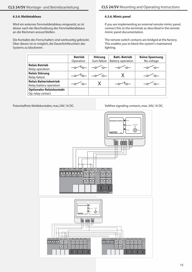
6.3.6. Mimic panel
If you are implementing an external remote mimic panel, connect this to the terminals as described in the remote mimic panel documentation.
The remote switch contacts are bridged at the factory. This enables you to block the system's maintained lighting.
Voltfree signaling contacts, max. 24V, 1A DC.
6.3.6. Meldetableau
Wird ein externes Fernmeldetableau eingesetzt, so ist dieses nach der Beschreibung des Fernmeldetableaus an die Klemmen anzuschließen.
Die Kontakte des Fernschalters sind werksseitig gebrückt. Über diesen ist es möglich, die Dauerlichtleuchten des Systems zu blockieren.
Potentialfreie Meldekontakte, max.24V, 1A DC.
BetriebOperation
StörungSum-failure
Batt.-BetriebBattery operation
Keine SpannungNo voltage
Relais BetriebRelay operationRelais StörungRelay failure XRelais BatteriebetriebRelay battery operation XOptionaler RelaiskontaktOp. relay contact
BetriebOperation
StörungSum-failure
Batt.-BetriebBattery operation
Keine SpannungNo voltage
Relais BetriebRelay operationRelais StörungRelay failure XRelais BatteriebetriebRelay battery operation XOptionaler RelaiskontaktOp. relay contact
Betrieb
Batt.-Betrieb
Störung
Ein
Aus
INOTEC MTB
Fernschalter
Meldetableau Notlicht
FS-FS+531+24V
T
IBpIBp FSSL+– +–
+24V+–
Opt.Stoer
Betr.Bat.-B.
SK1- +- +SK2- +- +
Betrieb
Batt.-Betrieb
Störung
Ein
Aus
INOTEC MTB
Fernschalter
Meldetableau Notlicht
FS-FS+531+24V
T
IBpIBp FSSL+– +–
+24V+–
Opt.Stoer
Betr.Bat.-B.
SK1- +- +SK2- +- +
FSSL+– +–
+24V+–
Opt.Stoer
Betr.Bat.-B.
SK1- +- +SK2- +- +
SK3- +- +SK4- +- +
FSSL+– +–
+24V+–
Opt.Stoer
Betr.Bat.-B.
SK1- +- +SK2- +- +
SK3- +- +SK4- +- +
Betrieb
Batt.-Betrieb
Störung
Ein
Aus
INOTEC MTB
Fernschalter
Meldetableau Notlicht
FS-FS+531+24V
T
FSSL+– +–
+24V+–
Opt.Stoer
Betr.Bat.-B.
SK1- +- +SK2- +- +
SK3- +- +SK4- +- +
FSSL+– +–
+24V+–
Opt.Stoer
Betr.Bat.-B.
SK1- +- +SK2- +- +
SK3- +- +SK4- +- +
Betrieb
Batt.-Betrieb
Störung
Ein
Aus
INOTEC MTB
Fernschalter
Meldetableau Notlicht
FS-FS+531+24V
T
16
CLS 24/SV Montage- und Betriebsanleitung CLS 24/SV Mounting and Operating Instructions
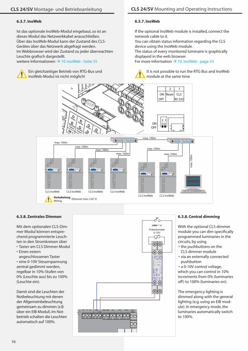
6.3.7. InoWeb
If the optional InoWeb module is installed, connect the network cable to it.You can obtain status information regarding the CLS device using the InoWeb module.The status of every monitored luminaire is graphically displayed in the web browser.For more information 10. InoWeb - page �5
It is not possible to run the RTG Bus and InoWeb module at the same time.
6.3.8. Central dimming
With the optional CLS dimmer module you can dim specifically programmed luminaries in the circuits, by using
the pushbuttons on the CLS dimmer modulevia an externally connected pushbutton a 0-10V control voltage,
which you can control in 10% increments from 0% (luminaries off ) to 100% (luminaries on).
The emergency lighting is dimmed along with the general lighting (e.g. using an EIB mod-ule). In emergency mode, the luminaries automatically switch to 100%.
•
•
•
6.3.7. InoWeb
Ist das optionale InoWeb-Modul eingebaut, so ist an dieses Modul das Netzwerkkabel anzuschließen.Über das InoWeb-Modul kann der Zustand des CLS-Gerätes über das Netzwerk abgefragt werden.Im Webbrowser wird der Zustand zu jeder überwachten Leuchte grafisch dargestellt.weitere Informationen 10. InoWeb - Seite �5
Ein gleichzeitiger Betrieb von RTG-Bus und InoWeb-Modul ist nicht möglich!
6.3.8. Zentrales Dimmen
Mit dem optionalen CLS-Dim-mer Modul können entspre-chend programmierte Leuch-ten in den Stromkreisen über
Taster am CLS Dimmer ModulEinen extern angeschlossenen Taster eine 0-10V Steuerspannung
zentral gedimmt werden, regelbar in 10%-Stufen von 0% (Leuchte aus) bis zu 100% (Leuchte ein).
Damit sind die Leuchten der Notbeleuchtung mit denen der Allgemeinbeleuchtung gemeinsam zu dimmen (z.B. über ein EIB-Modul). Im Not-betrieb schalten die Leuchten automatisch auf 100%.
••
•
HUB / Switch
InoWebControl
CLS InoWeb
INOTEC
1 2 3 4 5 6 7 8 9 10 11 12 13 14 15 16 17 18 19 20
SK 1 SK 2 SK 3 SK 4
Ein/On
StörungFailure
Ein/On
StörungFailure
Ein/On
StörungFailure
Ein/On
StörungFailure
Lade StörungCharge failure
StörungFailure
Batt.-BetriebBat.-Operation
BetriebOperation
OK
ESC
CLS InoWeb
INOTEC
1 2 3 4 5 6 7 8 9 10 11 12 13 14 15 16 17 18 19 20
SK 1 SK 2 SK 3 SK 4
Ein/On
StörungFailure
Ein/On
StörungFailure
Ein/On
StörungFailure
Ein/On
StörungFailure
Lade StörungCharge failure
StörungFailure
Batt.-BetriebBat.-Operation
BetriebOperation
OK
ESC
CLS InoWeb
INOTEC
1 2 3 4 5 6 7 8 9 10 11 12 13 14 15 16 17 18 19 20
SK 1 SK 2 SK 3 SK 4
Ein/On
StörungFailure
Ein/On
StörungFailure
Ein/On
StörungFailure
Ein/On
StörungFailure
Lade StörungCharge failure
StörungFailure
Batt.-BetriebBat.-Operation
BetriebOperation
OK
ESC
CLS InoWeb
INOTEC
1 2 3 4 5 6 7 8 9 10 11 12 13 14 15 16 17 18 19 20
SK 1 SK 2 SK 3 SK 4
Ein/On
StörungFailure
Ein/On
StörungFailure
Ein/On
StörungFailure
Ein/On
StörungFailure
Lade StörungCharge failure
StörungFailure
Batt.-BetriebBat.-Operation
BetriebOperation
OK
ESC
CLS InoWeb
INOTEC
1 2 3 4 5 6 7 8 9 10 11 12 13 14 15 16 17 18 19 20
SK 1 SK 2 SK 3 SK 4
Ein/On
StörungFailure
Ein/On
StörungFailure
Ein/On
StörungFailure
Ein/On
StörungFailure
Lade StörungCharge failure
StörungFailure
Batt.-BetriebBat.-Operation
BetriebOperation
OK
ESC
HUB / Switch
CLS InoWeb
max. 100m
VerkabelungEthernet (min. CAT 5)
Wiring
max. 100mmax. 100m
max. 100m
max. 100m
max. 100m
max. 100m
max
. 100
m
INOTEC
1 2 3 4 5 6 7 8 9 10 11 12 13 14 15 16 17 18 19 20
SK 1 SK 2 SK 3 SK 4
Ein/On
StörungFailure
Ein/On
StörungFailure
Ein/On
StörungFailure
Ein/On
StörungFailure
Lade StörungCharge failure
StörungFailure
Batt.-BetriebBat.-Operation
BetriebOperation
OK
ESC
HUB / Switch
InoWebControl
CLS InoWeb
INOTEC
1 2 3 4 5 6 7 8 9 10 11 12 13 14 15 16 17 18 19 20
SK 1 SK 2 SK 3 SK 4
Ein/On
StörungFailure
Ein/On
StörungFailure
Ein/On
StörungFailure
Ein/On
StörungFailure
Lade StörungCharge failure
StörungFailure
Batt.-BetriebBat.-Operation
BetriebOperation
OK
ESC
CLS InoWeb
INOTEC
1 2 3 4 5 6 7 8 9 10 11 12 13 14 15 16 17 18 19 20
SK 1 SK 2 SK 3 SK 4
Ein/On
StörungFailure
Ein/On
StörungFailure
Ein/On
StörungFailure
Ein/On
StörungFailure
Lade StörungCharge failure
StörungFailure
Batt.-BetriebBat.-Operation
BetriebOperation
OK
ESC
CLS InoWeb
INOTEC
1 2 3 4 5 6 7 8 9 10 11 12 13 14 15 16 17 18 19 20
SK 1 SK 2 SK 3 SK 4
Ein/On
StörungFailure
Ein/On
StörungFailure
Ein/On
StörungFailure
Ein/On
StörungFailure
Lade StörungCharge failure
StörungFailure
Batt.-BetriebBat.-Operation
BetriebOperation
OK
ESC
CLS InoWeb
INOTEC
1 2 3 4 5 6 7 8 9 10 11 12 13 14 15 16 17 18 19 20
SK 1 SK 2 SK 3 SK 4
Ein/On
StörungFailure
Ein/On
StörungFailure
Ein/On
StörungFailure
Ein/On
StörungFailure
Lade StörungCharge failure
StörungFailure
Batt.-BetriebBat.-Operation
BetriebOperation
OK
ESC
CLS InoWeb
INOTEC
1 2 3 4 5 6 7 8 9 10 11 12 13 14 15 16 17 18 19 20
SK 1 SK 2 SK 3 SK 4
Ein/On
StörungFailure
Ein/On
StörungFailure
Ein/On
StörungFailure
Ein/On
StörungFailure
Lade StörungCharge failure
StörungFailure
Batt.-BetriebBat.-Operation
BetriebOperation
OK
ESC
HUB / Switch
CLS InoWeb
max. 100m
VerkabelungEthernet (min. CAT 5)
Wiring
max. 100mmax. 100m
max. 100m
max. 100m
max. 100m
max. 100m
max
. 100
m
INOTEC
1 2 3 4 5 6 7 8 9 10 11 12 13 14 15 16 17 18 19 20
SK 1 SK 2 SK 3 SK 4
Ein/On
StörungFailure
Ein/On
StörungFailure
Ein/On
StörungFailure
Ein/On
StörungFailure
Lade StörungCharge failure
StörungFailure
Batt.-BetriebBat.-Operation
BetriebOperation
OK
ESC
2 1ON
OFF
2 1
ON
OFF
Reset CLS
RS 232
2 1ON
OFF
2 1
ON
OFF
Reset CLS
RS 232
R T G IBa IBpIBp+24V
T FSSL+– +–
+24V+–
Opt.Stoer
Potentiometer0-10V
oder / or
0 - 10V
Taster
Taster ext.
+24VBus
CLS
-Dim
me
rIN
OT
EC
850
013
TT
EMC
: ge
m. E
N 5
5015
Ta: -
15 b
is 40
°C
+ 0-10V - 0-10V
17
CLS 24/SV Montage- und Betriebsanleitung CLS 24/SV Mounting and Operating Instructions
7. Commissioning the CLS device
Before switching on the mains voltage and inserting the battery fuse, you must carry out the following tests:
Test all connections on the deviceTest the connection of the 24V current loop (SL+ / SL-)Check that the battery cells are properly connectedBefore carrying out the initial function or battery duration test, charge the batteries in the device for at least 24 hours
7.1. Switching OFF the CLS device
When switching off the CLS device, you must com-plete the following in this order
1. Block the emergency and maintained lighting2. Remove the battery fuse�. Switch off the mains supply
7.2. Switching ON the CLS device
When switching on the CLS device, complete the following in this order
1. Switch on the mains supply2. Insert the battery fuse
When the device starts up, the display indicates the operation, charging voltage and charging current.You must now make all the settings necessary for use. 8.�. Programming - page 21
7.3. Factory settings
Controller:
- Password: 0000- Operating time: 1h- InoWeb: activated, if installed- SL with monitoring loop function: deactivated- Remote switch with monitoring loop function: deactivated- Emergency lighting delay: 0 minutes- Manual reset: deactivated
All electric circuits are activated.
••••
7. Inbetriebnahme des CLS-Gerätes
Vor dem Einschalten der Netzspannung und Einset-zen der Batteriesicherung sind unbedingt folgende Prüfungen durchzuführen:
Prüfung aller Anschlüsse an das GerätPrüfung des Anschlusses der 24V-Stromschleife (SL+ / SL-)Prüfung der korrekten Verbindung der BatterieblöckeVor dem ersten Funktions- bzw. Betriebsdauertest sind die Batterien im Gerät min. 24 Stunden zu laden
7.1. Ausschalten des CLS-Gerätes
Beim Abschalten des CLS-Gerätes ist unbedingt fol-gende Reihenfolge zu beachten!
1. Anlage Notlicht und Dauerlicht blockieren2. Batteriesicherung entfernen�. Netz abschalten
7.2. Einschalten des CLS-Gerätes
Beim Einschalten ist diese Reihenfolge zu beachten
1. Netz einschalten2. Batteriesicherung einsetzen
Das Gerät wird initialisiert und im Display wird Betrieb, Ladespannung und Ladestrom angezeigt.Alle zum Betrieb notwendigen Einstellung müssen vor-genommen werden. 8.�. Programmierung - Seite 21
7.3. Lieferzustand
Steuerteil:
- Passwort: 0000- Betriebsdauer: 1h- InoWeb: aktiviert, wenn eingebaut- SL mit SLÜ: deaktiviert- FS mit SLÜ: deaktiviert- Notlichtnachlauf: 0 Minuten- Handrückschaltung: deaktiviert
Alle Stromkreise sind aktiviert.
••••
18
CLS 24/SV Montage- und Betriebsanleitung CLS 24/SV Mounting and Operating Instructions
8. Use
INOTEC
1 2 3 4 5 6 7 8 9 10 11 12 13 14 15 16 17 18 19 20
OK
ESC
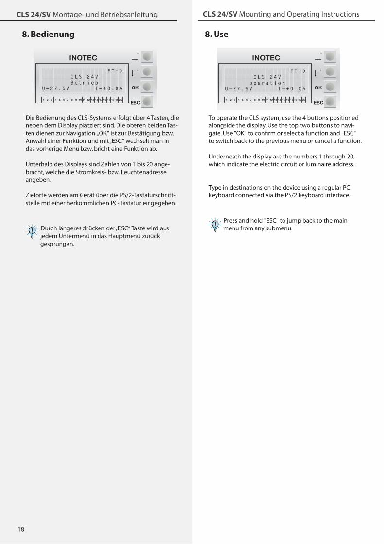
To operate the CLS system, use the 4 buttons positioned alongside the display. Use the top two buttons to navi-gate. Use "OK" to confirm or select a function and "ESC" to switch back to the previous menu or cancel a function.
Underneath the display are the numbers 1 through 20, which indicate the electric circuit or luminaire address.
Type in destinations on the device using a regular PC keyboard connected via the PS/2 keyboard interface.
Press and hold "ESC" to jump back to the main menu from any submenu.
8. Bedienung
INOTEC
1 2 3 4 5 6 7 8 9 10 11 12 13 14 15 16 17 18 19 20
OK
ESC
Die Bedienung des CLS-Systems erfolgt über 4 Tasten, die neben dem Display platziert sind. Die oberen beiden Tas-ten dienen zur Navigation. „OK“ ist zur Bestätigung bzw. Anwahl einer Funktion und mit „ESC“ wechselt man in das vorherige Menü bzw. bricht eine Funktion ab.
Unterhalb des Displays sind Zahlen von 1 bis 20 ange-bracht, welche die Stromkreis- bzw. Leuchtenadresse angeben.
Zielorte werden am Gerät über die PS/2-Tastaturschnitt-stelle mit einer herkömmlichen PC-Tastatur eingegeben.
Durch längeres drücken der „ESC“ Taste wird aus jedem Untermenü in das Hauptmenü zurück gesprungen.
F T - > C L S 2 4 V B e t r i e bU = 2 7 . 5 V I = + 0 . 0 A
F T - > C L S 2 4 V o p e r a t i o nU = 2 7 . 5 V I = + 0 . 0 A
19
CLS 24/SV Montage- und Betriebsanleitung CLS 24/SV Mounting and Operating Instructions
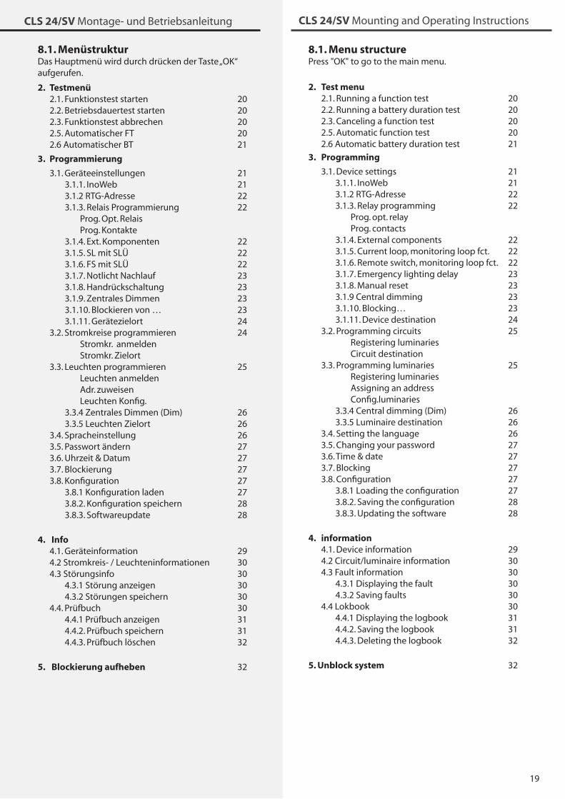
8.1. Menu structurePress "OK" to go to the main menu.
8.1. MenüstrukturDas Hauptmenü wird durch drücken der Taste „OK“aufgerufen. 2. Test menu
2.1. Running a function test 20 2.2. Running a battery duration test 20 2.�. Canceling a function test 20 2.5. Automatic function test 20 2.6 Automatic battery duration test 21
3. Programming
�.1. Device settings 21 �.1.1. InoWeb 21 �.1.2 RTG-Adresse 22 �.1.�. Relay programming 22 Prog. opt. relay Prog. contacts �.1.4. External components 22 �.1.5. Current loop, monitoring loop fct. 22 �.1.6. Remote switch, monitoring loop fct. 22 �.1.7. Emergency lighting delay 2� �.1.8. Manual reset 2� �.1.9 Central dimming 2� �.1.10. Blocking… 2� �.1.11. Device destination 24 �.2. Programming circuits 25 Registering luminaries Circuit destination �.�. Programming luminaries 25 Registering luminaries Assigning an address Config.luminaries �.�.4 Central dimming (Dim) 26 �.�.5 Luminaire destination 26 �.4. Setting the language 26 �.5. Changing your password 27 �.6. Time & date 27 �.7. Blocking 27 �.8. Configuration 27 �.8.1 Loading the configuration 27 �.8.2. Saving the configuration 28 �.8.�. Updating the software 28
4. information 4.1. Device information 29 4.2 Circuit/luminaire information �0 4.� Fault information �0 4.�.1 Displaying the fault �0 4.�.2 Saving faults �0 4.4 Lokbook �0 4.4.1 Displaying the logbook �1 4.4.2. Saving the logbook �1 4.4.�. Deleting the logbook �2
5. Unblock system �2
2. Testmenü 2.1. Funktionstest starten 20 2.2. Betriebsdauertest starten 20 2.�. Funktionstest abbrechen 20 2.5. Automatischer FT 20 2.6 Automatischer BT 21
3. Programmierung
�.1. Geräteeinstellungen 21 �.1.1. InoWeb 21 �.1.2 RTG-Adresse 22 �.1.�. Relais Programmierung 22 Prog. Opt. Relais Prog. Kontakte �.1.4. Ext. Komponenten 22 �.1.5. SL mit SLÜ 22 �.1.6. FS mit SLÜ 22 �.1.7. Notlicht Nachlauf 2� �.1.8. Handrückschaltung 2� �.1.9. Zentrales Dimmen 2� �.1.10. Blockieren von … 2� �.1.11. Gerätezielort 24 �.2. Stromkreise programmieren 24 Stromkr. anmelden Stromkr. Zielort �.�. Leuchten programmieren 25 Leuchten anmelden Adr. zuweisen Leuchten Konfig. �.�.4 Zentrales Dimmen (Dim) 26 �.�.5 Leuchten Zielort 26 �.4. Spracheinstellung 26 �.5. Passwort ändern 27 �.6. Uhrzeit & Datum 27 �.7. Blockierung 27 �.8. Konfiguration 27 �.8.1 Konfiguration laden 27 �.8.2. Konfiguration speichern 28 �.8.�. Softwareupdate 28
4. Info 4.1. Geräteinformation 29 4.2 Stromkreis- / Leuchteninformationen �0 4.� Störungsinfo �0 4.�.1 Störung anzeigen �0 4.�.2 Störungen speichern �0 4.4. Prüfbuch �0 4.4.1 Prüfbuch anzeigen �1 4.4.2. Prüfbuch speichern �1 4.4.�. Prüfbuch löschen �2
5. Blockierung aufheben �2
20
CLS 24/SV Montage- und Betriebsanleitung CLS 24/SV Mounting and Operating Instructions
8.2. "Test menu"
8.2.1. Running a function testIn function test mode, the device switches to battery mode and checks that the connected and registered luminaries are working accordingly. The results of the function test are saved in the logbook and are shown on the display if there is a luminaire failure.
After a luminaire is repaired, carry out a new function test to resolve the fault.
OK test menu OK FT start OK
8.2.2. Running a battery duration testThe battery duration test switches the CLS device into battery mode and calculates the maximum runtime until the battery's deep discharge protection comes into effect.
OK test menu OK start DT OK
8.2.3. Canceling a function test
OK test menu OK cancel FT OK
You can use this command to cancel a running function test.
You can also use the top button "stop FT" on the main screen to cancel a running function test.
8.2.4. Canceling a battery duration testOK test menu OK cancel DT OK
If a battery duration test was started unintentionally, you can cancel it manually using the "cancel DT" command from the test menu.
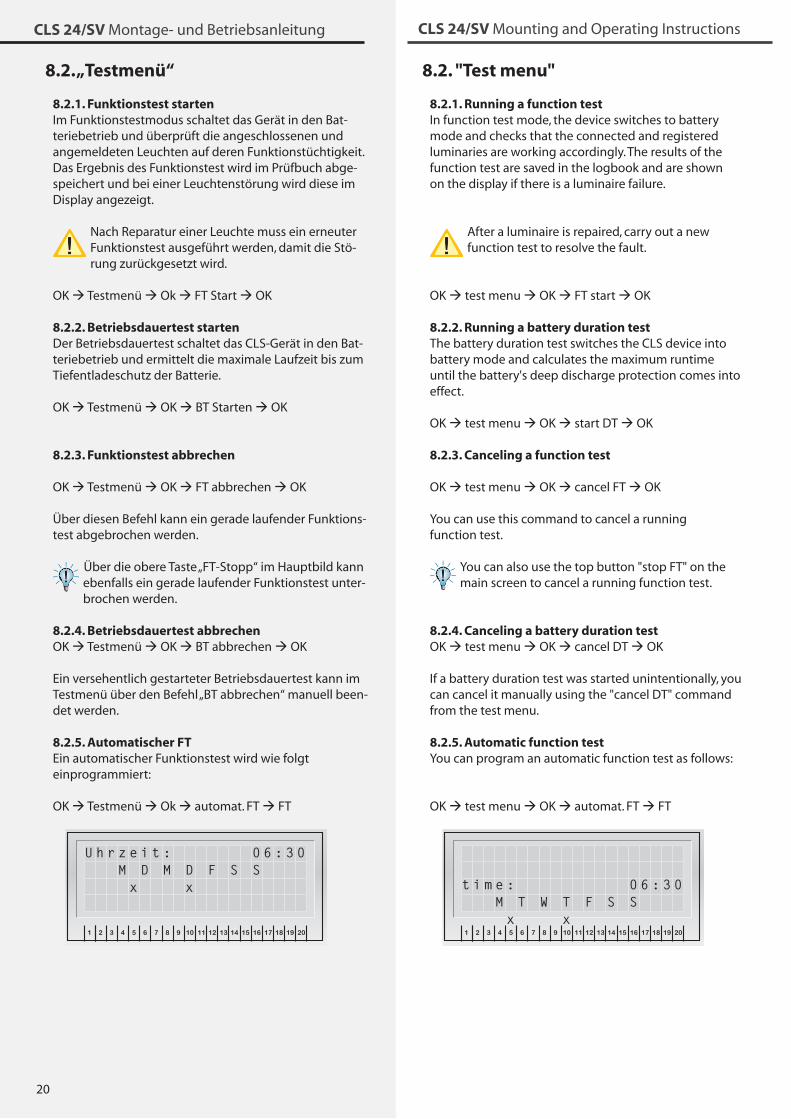
8.2.5. Automatic function testYou can program an automatic function test as follows:
OK test menu OK automat. FT FTINOTEC
1 2 3 4 5 6 7 8 9 10 11 12 13 14 15 16 17 18 19 20
OK
ESC
8.2. „Testmenü“
8.2.1. Funktionstest startenIm Funktionstestmodus schaltet das Gerät in den Bat-teriebetrieb und überprüft die angeschlossenen und angemeldeten Leuchten auf deren Funktionstüchtigkeit. Das Ergebnis des Funktionstest wird im Prüfbuch abge-speichert und bei einer Leuchtenstörung wird diese im Display angezeigt.
Nach Reparatur einer Leuchte muss ein erneuter Funktionstest ausgeführt werden, damit die Stö-rung zurückgesetzt wird.
OK Testmenü Ok FT Start OK
8.2.2. Betriebsdauertest startenDer Betriebsdauertest schaltet das CLS-Gerät in den Bat-teriebetrieb und ermittelt die maximale Laufzeit bis zum Tiefentladeschutz der Batterie.
OK Testmenü OK BT Starten OK
8.2.3. Funktionstest abbrechen
OK Testmenü OK FT abbrechen OK
Über diesen Befehl kann ein gerade laufender Funktions-test abgebrochen werden.
Über die obere Taste „FT-Stopp“ im Hauptbild kann ebenfalls ein gerade laufender Funktionstest unter-brochen werden.
8.2.4. Betriebsdauertest abbrechenOK Testmenü OK BT abbrechen OK
Ein versehentlich gestarteter Betriebsdauertest kann im Testmenü über den Befehl „BT abbrechen“ manuell been-det werden.
8.2.5. Automatischer FTEin automatischer Funktionstest wird wie folgt einprogrammiert:
OK Testmenü Ok automat. FT FTINOTEC
1 2 3 4 5 6 7 8 9 10 11 12 13 14 15 16 17 18 19 20
OK
ESC
U h r z e i t : 0 6 : 3 0 M D M D F S S x x t i m e : 0 6 : 3 0
M T W T F S S x x
21
CLS 24/SV Montage- und Betriebsanleitung CLS 24/SV Mounting and Operating Instructions
Use the two top buttons to set the time. Press "OK" to continue. You can also set the day of the week you want the function test to run on. The CLS system will then start the function test at the specified time each week.
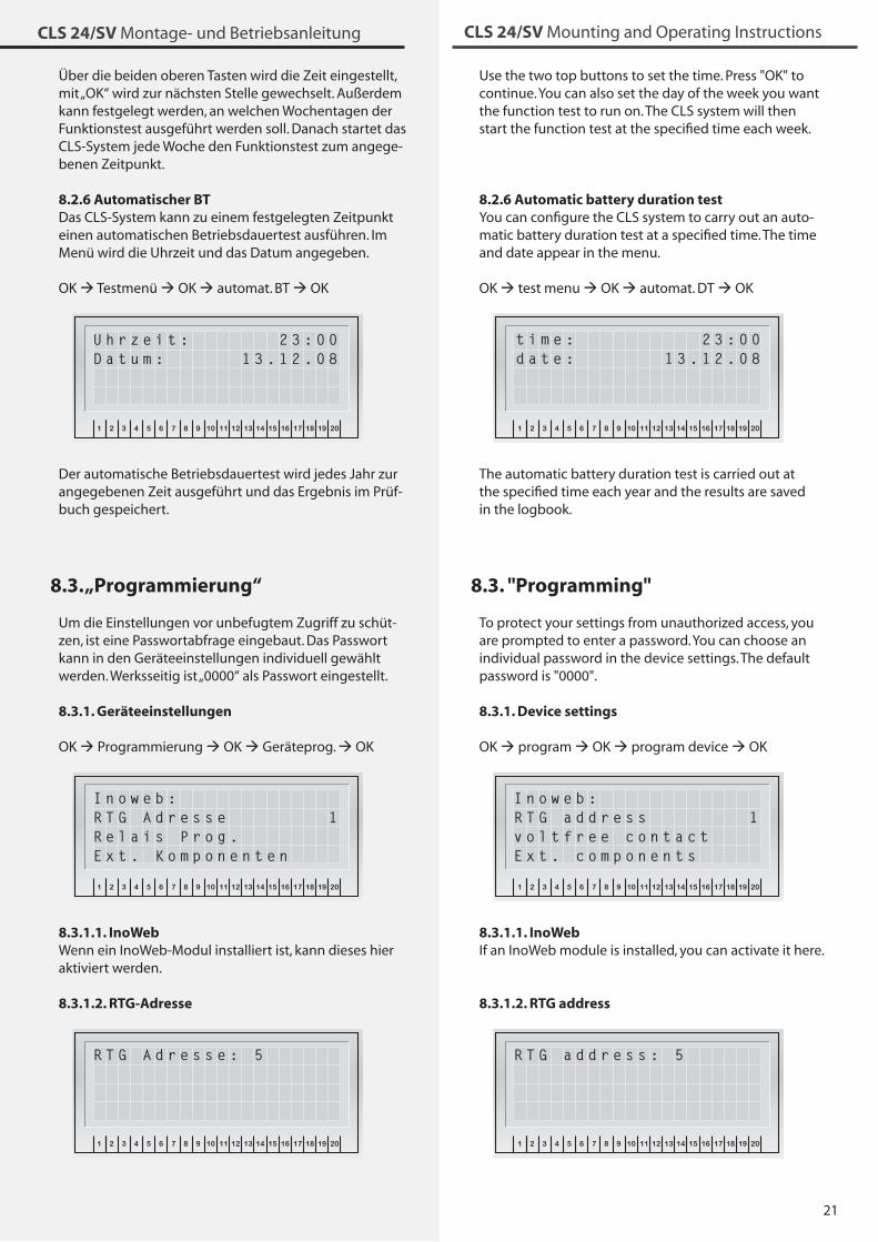
8.2.6 Automatic battery duration testYou can configure the CLS system to carry out an auto-matic battery duration test at a specified time. The time and date appear in the menu.
OK test menu OK automat. DT OKINOTEC
1 2 3 4 5 6 7 8 9 10 11 12 13 14 15 16 17 18 19 20
OK
ESC
The automatic battery duration test is carried out at the specified time each year and the results are saved in the logbook.
8.3. "Programming"
To protect your settings from unauthorized access, you are prompted to enter a password. You can choose an individual password in the device settings. The default password is "0000".
8.3.1. Device settings
OK program OK program device OKINOTEC
1 2 3 4 5 6 7 8 9 10 11 12 13 14 15 16 17 18 19 20
OK
ESC
I n o w e b :R T G a d d r e s s 1v o l t f r e e c o n t a c tE x t . c o m p o n e n t s
8.3.1.1. InoWebIf an InoWeb module is installed, you can activate it here.
8.3.1.2. RTG addressINOTEC
1 2 3 4 5 6 7 8 9 10 11 12 13 14 15 16 17 18 19 20
OK
ESC
R T G a d d r e s s : 5
Über die beiden oberen Tasten wird die Zeit eingestellt, mit „OK“ wird zur nächsten Stelle gewechselt. Außerdem kann festgelegt werden, an welchen Wochentagen der Funktionstest ausgeführt werden soll. Danach startet das CLS-System jede Woche den Funktionstest zum angege-benen Zeitpunkt.
8.2.6 Automatischer BTDas CLS-System kann zu einem festgelegten Zeitpunkt einen automatischen Betriebsdauertest ausführen. Im Menü wird die Uhrzeit und das Datum angegeben.
OK Testmenü OK automat. BT OKINOTEC
1 2 3 4 5 6 7 8 9 10 11 12 13 14 15 16 17 18 19 20
OK
ESC
U h r z e i t : 2 3 : 0 0D a t u m : 1 3 . 1 2 . 0 8
Der automatische Betriebsdauertest wird jedes Jahr zur angegebenen Zeit ausgeführt und das Ergebnis im Prüf-buch gespeichert.
8.3. „Programmierung“
Um die Einstellungen vor unbefugtem Zugriff zu schüt-zen, ist eine Passwortabfrage eingebaut. Das Passwort kann in den Geräteeinstellungen individuell gewählt werden. Werksseitig ist „0000“ als Passwort eingestellt.
8.3.1. Geräteeinstellungen
OK Programmierung OK Geräteprog. OKINOTEC
1 2 3 4 5 6 7 8 9 10 11 12 13 14 15 16 17 18 19 20
OK
ESC
I n o w e b :R T G A d r e s s e 1R e l a i s P r o g .E x t . K o m p o n e n t e n
8.3.1.1. InoWebWenn ein InoWeb-Modul installiert ist, kann dieses hier aktiviert werden.
8.3.1.2. RTG-AdresseINOTEC
1 2 3 4 5 6 7 8 9 10 11 12 13 14 15 16 17 18 19 20
OK
ESC
R T G A d r e s s e : 5
t i m e : 2 3 : 0 0d a t e : 1 3 . 1 2 . 0 8
22
CLS 24/SV Montage- und Betriebsanleitung CLS 24/SV Mounting and Operating Instructions
If the CLS device is centrally monitored on the mimic panel, specify the device address in this menu (0-�2). Entering 0 will deactivate data communication to the mimic panel.
If the system is monitored using the INOWEB module, you must enter the address as 0 and activate the InoWeb option. 8.4.1.2
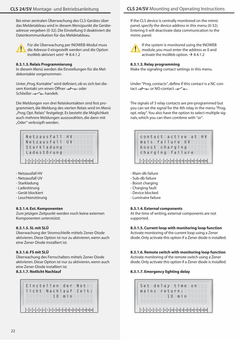
8.3.1.3. Relay programmingMake the signaling contact settings in this menu.
Under "Prog. contacts", define if this contact is a NC-con-tact or NO-contact .
The signals of � relay contacts are pre-programmed but you can set the signal for the 4th relay in the menu "Prog. opt. relay". You also have the option to select multiple sig-nals, which you can then combine with "or".
INOTEC
1 2 3 4 5 6 7 8 9 10 11 12 13 14 15 16 17 18 19 20
OK
ESC
c o n t a c t a c t i v e a t H Vm a i s f a i l u r e U Vb o o s t c h a r g i n gc h a r g i n g f a i l u r e
- Main-db failure- Sub-db failure- Boost charging- Charging fault- Device blocked- Luminaire failure
8.3.1.4. External componentsAt the time of writing, external components are not supported.
8.3.1.5. Current loop with monitoring loop functionActivate monitoring of the current loop using a Zener diode. Only activate this option if a Zener diode is installed.
8.3.1.6. Remote switch with monitoring loop functionActivate monitoring of the remote switch using a Zener diode. Only activate this option if a Zener diode is installed.
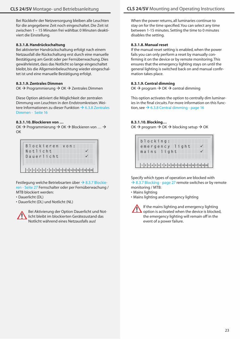
8.3.1.7. Emergency lighting delayINOTEC
1 2 3 4 5 6 7 8 9 10 11 12 13 14 15 16 17 18 19 20
OK
ESC
S e t d e l a y t i m e o n m a i n s r e t u r n : 1 0 m i n
Bei einer zentralen Überwachung des CLS-Gerätes über das Meldetableau wird in diesem Menüpunkt die Geräte-adresse vergeben (0-�2). Die Einstellung 0 deaktiviert die Datenkommunikation für das Meldetableau.
Für die Überwachung per INOWEB-Modul muss die Adresse 0 eingestellt werden und die Option InoWeb aktiviert sein! 8.4.1.2
8.3.1.3. Relais ProgrammierungIn diesem Menü werden die Einstellungen für die Mel-dekontakte vorgenommen.
Unter „Prog. Kontakte“ wird definiert, ob es sich bei die-sem Kontakt um einen Öffner oder Schließer handelt.
Die Meldungen von drei Relaiskontakten sind fest pro-grammiert, die Meldung des vierten Relais wird im Menü „Prog. Opt. Relais“ festgelegt. Es besteht die Möglichkeit auch mehrere Meldungen auszuwählen, die dann mit „Oder“ verknüpft werden.
INOTEC
1 2 3 4 5 6 7 8 9 10 11 12 13 14 15 16 17 18 19 20
OK
ESC
N e t z a u s f a l l H VN e t z a u s f a l l U VS t a r k l a d u n gL a d e s t ö r u n g
- Netzausfall HV- Netzausfall UV- Starkladung- Ladestörung- Gerät blockiert- Leuchtenstörung
8.3.1.4. Ext. KomponentenZum jetzigen Zeitpunkt werden noch keine externen Komponenten unterstützt.
8.3.1.5. SL mit SLÜÜberwachung der Stromschleife mittels Zener-Diode aktivieren. Diese Option ist nur zu aktivieren, wenn auch eine Zener-Diode installiert ist.
8.3.1.6. FS mit SLÜÜberwachung des Fernschalters mittels Zener-Diode aktivieren. Diese Option ist nur zu aktivieren, wenn auch eine Zener-Diode installiert ist.8.3.1.7. Notlicht Nachlauf
INOTEC
1 2 3 4 5 6 7 8 9 10 11 12 13 14 15 16 17 18 19 20
OK
ESC
E i n s t e l l e n d e r N o t -l i c h t N a c h l a u f Z e i t : 1 0 m i n
2�
CLS 24/SV Montage- und Betriebsanleitung CLS 24/SV Mounting and Operating Instructions
Bei Rückkehr der Netzversorgung bleiben alle Leuchten für die angegebene Zeit noch eingeschaltet. Die Zeit ist zwischen 1 – 15 Minuten frei wählbar. 0 Minuten deakti-viert die Einstellung.
8.3.1.8. HandrückschaltungBei aktivierter Handrückschaltung erfolgt nach einem Netzausfall die Rückschaltung erst durch eine manuelle Bestätigung am Gerät oder per Fernüberwachung. Dies gewährleistet, dass das Notlicht so lange eingeschaltet bleibt, bis die Allgemeinbeleuchtung wieder eingeschal-tet ist und eine manuelle Bestätigung erfolgt.
8.3.1.9. Zentrales DimmenOK Programmierung OK Zentrales Dimmen
Diese Option aktiviert die Möglichkeit der zentralen Dimmung von Leuchten in den Endstromkreisen. Wei-tere Informationen zu dieser Funktion 6.�.8 Zentrales Dimmen - Seite 16
8.3.1.10. Blockieren von …OK Programmierung OK Blockieren von … OK
INOTEC
1 2 3 4 5 6 7 8 9 10 11 12 13 14 15 16 17 18 19 20
OK
ESC
B l o c k i e r e n v o n :N o t l i c h t D a u e r l i c h t
Festlegung welche Betriebsarten über 8.�.7 Blockie-ren - Seite 27 Fernschalter oder per Fernüberwachung / MTB blockiert werden:
Dauerlicht (DL)Dauerlicht (DL) und Notlicht (NL)
Bei Aktivierung der Option Dauerlicht und Not-licht bleibt im blockierten Gerätezustand das Notlicht während eines Netzausfalls aus!
••
When the power returns, all luminaries continue to stay on for the time specified. You can select any time between 1-15 minutes. Setting the time to 0 minutes disables the setting.
8.3.1.8. Manual resetIf the manual reset setting is enabled, when the power fails you can only perform a reset by manually con-firming it on the device or by remote monitoring. This ensures that the emergency lighting stays on until the general lighting is switched back on and manual confir-mation takes place.
8.3.1.9. Central dimmingOK program OK central dimming
This option activates the option to centrally dim luminar-ies in the final circuits. For more information on this func-tion, see 6.�.8 Central dimming - page 16
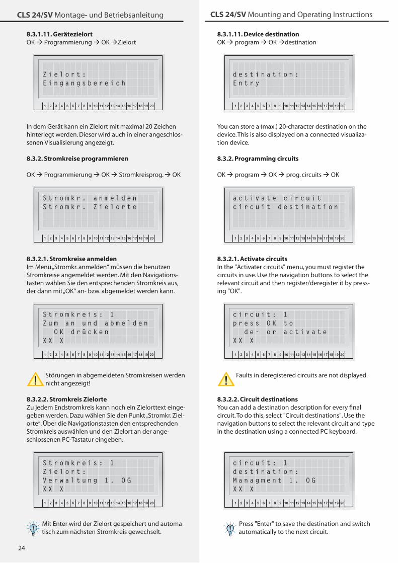
8.3.1.10. Blocking…OK program OK blocking setup OK
INOTEC
1 2 3 4 5 6 7 8 9 10 11 12 13 14 15 16 17 18 19 20
OK
ESC
b l o c k i n g :e m e r g e n c y l i g h t m a i n s l i g h t
Specify which types of operation are blocked with 8.�.7 Blocking - page 27 remote switches or by remote monitoring / MTB:
Mains lightingMains lighting and emergency lighting
If the mains lighting and emergency lighting option is activated when the device is blocked, the emergency lighting will remain off in the event of a power failure.
••
24
CLS 24/SV Montage- und Betriebsanleitung CLS 24/SV Mounting and Operating Instructions
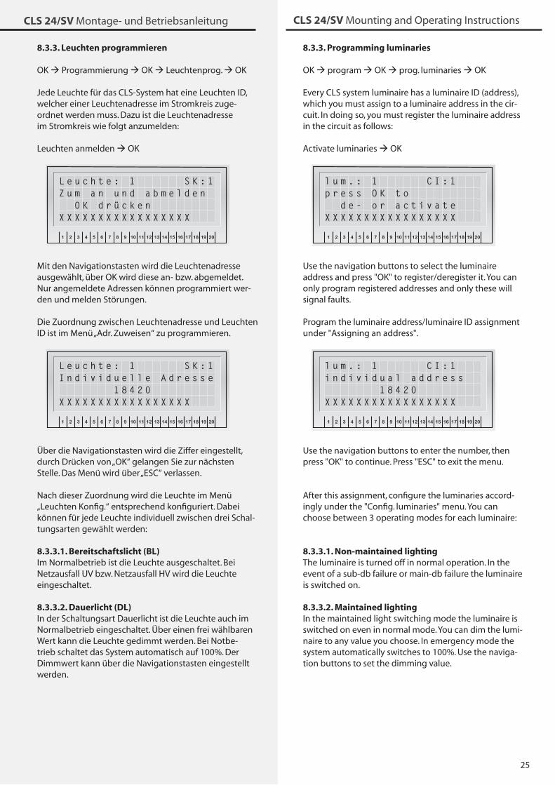
8.3.1.11. Device destinationOK program OK destination
INOTEC
1 2 3 4 5 6 7 8 9 10 11 12 13 14 15 16 17 18 19 20
OK
ESC
d e s t i n a t i o n :E n t r y
You can store a (max.) 20-character destination on the device. This is also displayed on a connected visualiza-tion device.
8.3.2. Programming circuits
OK program OK prog. circuits OKINOTEC
1 2 3 4 5 6 7 8 9 10 11 12 13 14 15 16 17 18 19 20
OK
ESC
a c t i v a t e c i r c u i tc i r c u i t d e s t i n a t i o n
8.3.2.1. Activate circuitsIn the "Activater circuits" menu, you must register the circuits in use. Use the navigation buttons to select the relevant circuit and then register/deregister it by press-ing "OK".
INOTEC
1 2 3 4 5 6 7 8 9 10 11 12 13 14 15 16 17 18 19 20
OK
ESC
c i r c u i t : 1p r e s s O K t o d e - o r a c t i v a t eX X X
Faults in deregistered circuits are not displayed.
8.3.2.2. Circuit destinations You can add a destination description for every final circuit. To do this, select "Circuit destinations". Use the navigation buttons to select the relevant circuit and type in the destination using a connected PC keyboard.
INOTEC
1 2 3 4 5 6 7 8 9 10 11 12 13 14 15 16 17 18 19 20
OK
ESC
c i r c u i t : 1d e s t i n a t i o n :M a n a g m e n t 1 . O GX X X
Press "Enter" to save the destination and switch automatically to the next circuit.
8.3.1.11. GerätezielortOK Programmierung OK Zielort
INOTEC
1 2 3 4 5 6 7 8 9 10 11 12 13 14 15 16 17 18 19 20
OK
ESC
Z i e l o r t :E i n g a n g s b e r e i c h
In dem Gerät kann ein Zielort mit maximal 20 Zeichen hinterlegt werden. Dieser wird auch in einer angeschlos-senen Visualisierung angezeigt.
8.3.2. Stromkreise programmieren
OK Programmierung OK Stromkreisprog. OKINOTEC
1 2 3 4 5 6 7 8 9 10 11 12 13 14 15 16 17 18 19 20
OK
ESC
S t r o m k r . a n m e l d e nS t r o m k r . Z i e l o r t e
8.3.2.1. Stromkreise anmeldenIm Menü „Stromkr. anmelden“ müssen die benutzen Stromkreise angemeldet werden. Mit den Navigations-tasten wählen Sie den entsprechenden Stromkreis aus, der dann mit „OK“ an- bzw. abgemeldet werden kann.
INOTEC
1 2 3 4 5 6 7 8 9 10 11 12 13 14 15 16 17 18 19 20
OK
ESC
S t r o m k r e i s : 1Z u m a n u n d a b m e l d e n O K d r ü c k e nX X X
Störungen in abgemeldeten Stromkreisen werden nicht angezeigt!
8.3.2.2. Stromkreis Zielorte Zu jedem Endstromkreis kann noch ein Zielorttext einge-geben werden. Dazu wählen Sie den Punkt „Stromkr. Ziel-orte“. Über die Navigationstasten den entsprechenden Stromkreis auswählen und den Zielort an der ange-schlossenen PC-Tastatur eingeben.
INOTEC
1 2 3 4 5 6 7 8 9 10 11 12 13 14 15 16 17 18 19 20
OK
ESC
S t r o m k r e i s : 1Z i e l o r t :V e r w a l t u n g 1 . O GX X X
Mit Enter wird der Zielort gespeichert und automa-tisch zum nächsten Stromkreis gewechselt.
25
CLS 24/SV Montage- und Betriebsanleitung CLS 24/SV Mounting and Operating Instructions
8.3.3. Programming luminaries
OK program OK prog. luminaries OK
Every CLS system luminaire has a luminaire ID (address), which you must assign to a luminaire address in the cir-cuit. In doing so, you must register the luminaire address in the circuit as follows:
Activate luminaries OK INOTEC
1 2 3 4 5 6 7 8 9 10 11 12 13 14 15 16 17 18 19 20
OK
ESC
l u m . : 1 C I : 1p r e s s O K t o d e - o r a c t i v a t eX X X X X X X X X X X X X X X X X
Use the navigation buttons to select the luminaire address and press "OK" to register/deregister it. You can only program registered addresses and only these will signal faults.
Program the luminaire address/luminaire ID assignment under "Assigning an address".
INOTEC
1 2 3 4 5 6 7 8 9 10 11 12 13 14 15 16 17 18 19 20
OK
ESC
l u m . : 1 C I : 1i n d i v i d u a l a d d r e s s 1 8 4 2 0X X X X X X X X X X X X X X X X X
Use the navigation buttons to enter the number, then press "OK" to continue. Press "ESC" to exit the menu.
After this assignment, configure the luminaries accord-ingly under the "Config. luminaries" menu. You can choose between � operating modes for each luminaire:
8.3.3.1. Non-maintained lightingThe luminaire is turned off in normal operation. In the event of a sub-db failure or main-db failure the luminaire is switched on.
8.3.3.2. Maintained lightingIn the maintained light switching mode the luminaire is switched on even in normal mode. You can dim the lumi-naire to any value you choose. In emergency mode the system automatically switches to 100%. Use the naviga-tion buttons to set the dimming value.
8.3.3. Leuchten programmieren
OK Programmierung OK Leuchtenprog. OK
Jede Leuchte für das CLS-System hat eine Leuchten ID, welcher einer Leuchtenadresse im Stromkreis zuge-ordnet werden muss. Dazu ist die Leuchtenadresse im Stromkreis wie folgt anzumelden:
Leuchten anmelden OK INOTEC
1 2 3 4 5 6 7 8 9 10 11 12 13 14 15 16 17 18 19 20
OK
ESC
L e u c h t e : 1 S K : 1Z u m a n u n d a b m e l d e n O K d r ü c k e nX X X X X X X X X X X X X X X X X
Mit den Navigationstasten wird die Leuchtenadresse ausgewählt, über OK wird diese an- bzw. abgemeldet. Nur angemeldete Adressen können programmiert wer-den und melden Störungen.
Die Zuordnung zwischen Leuchtenadresse und Leuchten ID ist im Menü „Adr. Zuweisen“ zu programmieren.
INOTEC
1 2 3 4 5 6 7 8 9 10 11 12 13 14 15 16 17 18 19 20
OK
ESC
L e u c h t e : 1 S K : 1I n d i v i d u e l l e A d r e s s e 1 8 4 2 0X X X X X X X X X X X X X X X X X
Über die Navigationstasten wird die Ziffer eingestellt, durch Drücken von „OK“ gelangen Sie zur nächsten Stelle. Das Menü wird über „ESC“ verlassen.
Nach dieser Zuordnung wird die Leuchte im Menü „Leuchten Konfig.“ entsprechend konfiguriert. Dabei können für jede Leuchte individuell zwischen drei Schal-tungsarten gewählt werden:
8.3.3.1. Bereitschaftslicht (BL)Im Normalbetrieb ist die Leuchte ausgeschaltet. Bei Netzausfall UV bzw. Netzausfall HV wird die Leuchte eingeschaltet.
8.3.3.2. Dauerlicht (DL)In der Schaltungsart Dauerlicht ist die Leuchte auch im Normalbetrieb eingeschaltet. Über einen frei wählbaren Wert kann die Leuchte gedimmt werden. Bei Notbe-trieb schaltet das System automatisch auf 100%. Der Dimmwert kann über die Navigationstasten eingestellt werden.
26
CLS 24/SV Montage- und Betriebsanleitung CLS 24/SV Mounting and Operating Instructions
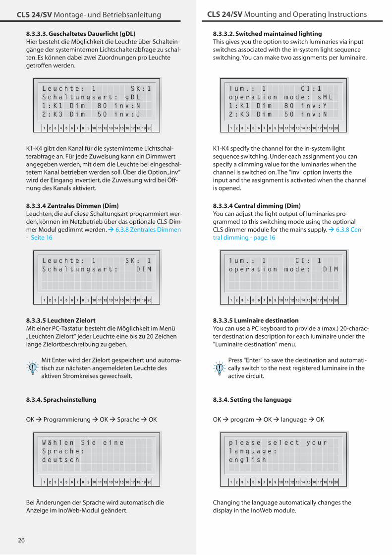
8.3.3.2. Switched maintained lightingThis gives you the option to switch luminaries via input switches associated with the in-system light sequence switching. You can make two assignments per luminaire.
INOTEC
1 2 3 4 5 6 7 8 9 10 11 12 13 14 15 16 17 18 19 20
OK
ESC
l u m . : 1 C I : 1o p e r a t i o n m o d e : s M L1 : K 1 D i m 8 0 i n v : Y2 : K 3 D i m 5 0 i n v : N
K1-K4 specify the channel for the in-system light sequence switching. Under each assignment you can specify a dimming value for the luminaries when the channel is switched on. The "inv" option inverts the input and the assignment is activated when the channel is opened.
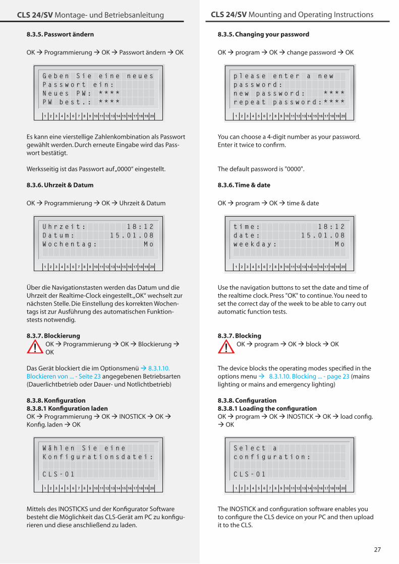
8.3.3.4 Central dimming (Dim)You can adjust the light output of luminaries pro-grammed to this switching mode using the optional CLS dimmer module for the mains supply. 6.�.8 Cen-tral dimming - page 16
INOTEC
1 2 3 4 5 6 7 8 9 10 11 12 13 14 15 16 17 18 19 20
OK
ESC
l u m . : 1 C I : 1o p e r a t i o n m o d e : D I M
8.3.3.5 Luminaire destinationYou can use a PC keyboard to provide a (max.) 20-charac-ter destination description for each luminaire under the "Luminaire destination" menu.
Press "Enter" to save the destination and automati-cally switch to the next registered luminaire in the active circuit.
8.3.4. Setting the language
OK program OK language OKINOTEC
1 2 3 4 5 6 7 8 9 10 11 12 13 14 15 16 17 18 19 20
OK
ESC
p l e a s e s e l e c t y o u rl a n g u a g e :e n g l i s h
Changing the language automatically changes the display in the InoWeb module.
8.3.3.3. Geschaltetes Dauerlicht (gDL)Hier besteht die Möglichkeit die Leuchte über Schaltein-gänge der systeminternen Lichtschalterabfrage zu schal-ten. Es können dabei zwei Zuordnungen pro Leuchte getroffen werden.
INOTEC
1 2 3 4 5 6 7 8 9 10 11 12 13 14 15 16 17 18 19 20
OK
ESC
L e u c h t e : 1 S K : 1S c h a l t u n g s a r t : g D L1 : K 1 D i m 8 0 i n v : N2 : K 3 D i m 5 0 i n v : J
K1-K4 gibt den Kanal für die systeminterne Lichtschal-terabfrage an. Für jede Zuweisung kann ein Dimmwert angegeben werden, mit dem die Leuchte bei eingeschal-tetem Kanal betrieben werden soll. Über die Option „inv“ wird der Eingang invertiert, die Zuweisung wird bei Öff-nung des Kanals aktiviert.
8.3.3.4 Zentrales Dimmen (Dim)Leuchten, die auf diese Schaltungsart programmiert wer-den, können im Netzbetrieb über das optionale CLS-Dim-mer Modul gedimmt werden. 6.�.8 Zentrales Dimmen - Seite 16
INOTEC
1 2 3 4 5 6 7 8 9 10 11 12 13 14 15 16 17 18 19 20
OK
ESC
L e u c h t e : 1 S K : 1S c h a l t u n g s a r t : D I M
8.3.3.5 Leuchten ZielortMit einer PC-Tastatur besteht die Möglichkeit im Menü „Leuchten Zielort“ jeder Leuchte eine bis zu 20 Zeichen lange Zielortbeschreibung zu geben.
Mit Enter wird der Zielort gespeichert und automa-tisch zur nächsten angemeldeten Leuchte des aktiven Stromkreises gewechselt.
8.3.4. Spracheinstellung
OK Programmierung OK Sprache OKINOTEC
1 2 3 4 5 6 7 8 9 10 11 12 13 14 15 16 17 18 19 20
OK
ESC
W ä h l e n S i e e i n eS p r a c h e :d e u t s c h
Bei Änderungen der Sprache wird automatisch die Anzeige im InoWeb-Modul geändert.
27
CLS 24/SV Montage- und Betriebsanleitung CLS 24/SV Mounting and Operating Instructions
8.3.5. Changing your password
OK program OK change password OKINOTEC
1 2 3 4 5 6 7 8 9 10 11 12 13 14 15 16 17 18 19 20
OK
ESC
p l e a s e e n t e r a n e w p a s s w o r d :n e w p a s s w o r d : * * * *r e p e a t p a s s w o r d : * * * *
You can choose a 4-digit number as your password. Enter it twice to confirm.
The default password is "0000".
8.3.6. Time & date
OK program OK time & date INOTEC
1 2 3 4 5 6 7 8 9 10 11 12 13 14 15 16 17 18 19 20
OK
ESC
t i m e : 1 8 : 1 2d a t e : 1 5 . 0 1 . 0 8w e e k d a y : M o
Use the navigation buttons to set the date and time of the realtime clock. Press "OK" to continue. You need to set the correct day of the week to be able to carry out automatic function tests.
8.3.7. Blocking OK program OK block OK
The device blocks the operating modes specified in the options menu 8.�.1.10. Blocking ... - page 2� (mains lighting or mains and emergency lighting)
8.3.8. Configuration8.3.8.1 Loading the configurationOK program OK INOSTICK OK load config. OK
INOTEC
1 2 3 4 5 6 7 8 9 10 11 12 13 14 15 16 17 18 19 20
OK
ESC
S e l e c t a c o n f i g u r a t i o n :
C L S - 0 1
The INOSTICK and configuration software enables you to configure the CLS device on your PC and then upload it to the CLS.
8.3.5. Passwort ändern
OK Programmierung OK Passwort ändern OKINOTEC
1 2 3 4 5 6 7 8 9 10 11 12 13 14 15 16 17 18 19 20
OK
ESC
G e b e n S i e e i n e n e u e sP a s s w o r t e i n :N e u e s P W : * * * *P W b e s t . : * * * *
Es kann eine vierstellige Zahlenkombination als Passwort gewählt werden. Durch erneute Eingabe wird das Pass-wort bestätigt.
Werksseitig ist das Passwort auf „0000“ eingestellt.
8.3.6. Uhrzeit & Datum
OK Programmierung OK Uhrzeit & DatumINOTEC
1 2 3 4 5 6 7 8 9 10 11 12 13 14 15 16 17 18 19 20
OK
ESC
U h r z e i t : 1 8 : 1 2D a t u m : 1 5 . 0 1 . 0 8W o c h e n t a g : M o
Über die Navigationstasten werden das Datum und die Uhrzeit der Realtime-Clock eingestellt. „OK“ wechselt zur nächsten Stelle. Die Einstellung des korrekten Wochen-tags ist zur Ausführung des automatischen Funktion-stests notwendig.
8.3.7. Blockierung OK Programmierung OK Blockierung OK
Das Gerät blockiert die im Optionsmenü 8.�.1.10. Blockieren von ... - Seite 2� angegebenen Betriebsarten (Dauerlichtbetrieb oder Dauer- und Notlichtbetrieb)
8.3.8. Konfiguration8.3.8.1 Konfiguration ladenOK Programmierung OK INOSTICK OK Konfig. laden OK
INOTEC
1 2 3 4 5 6 7 8 9 10 11 12 13 14 15 16 17 18 19 20
OK
ESC
W ä h l e n S i e e i n e K o n f i g u r a t i o n s d a t e i :
C L S - 0 1
Mittels des INOSTICKS und der Konfigurator Software besteht die Möglichkeit das CLS-Gerät am PC zu konfigu-rieren und diese anschließend zu laden.
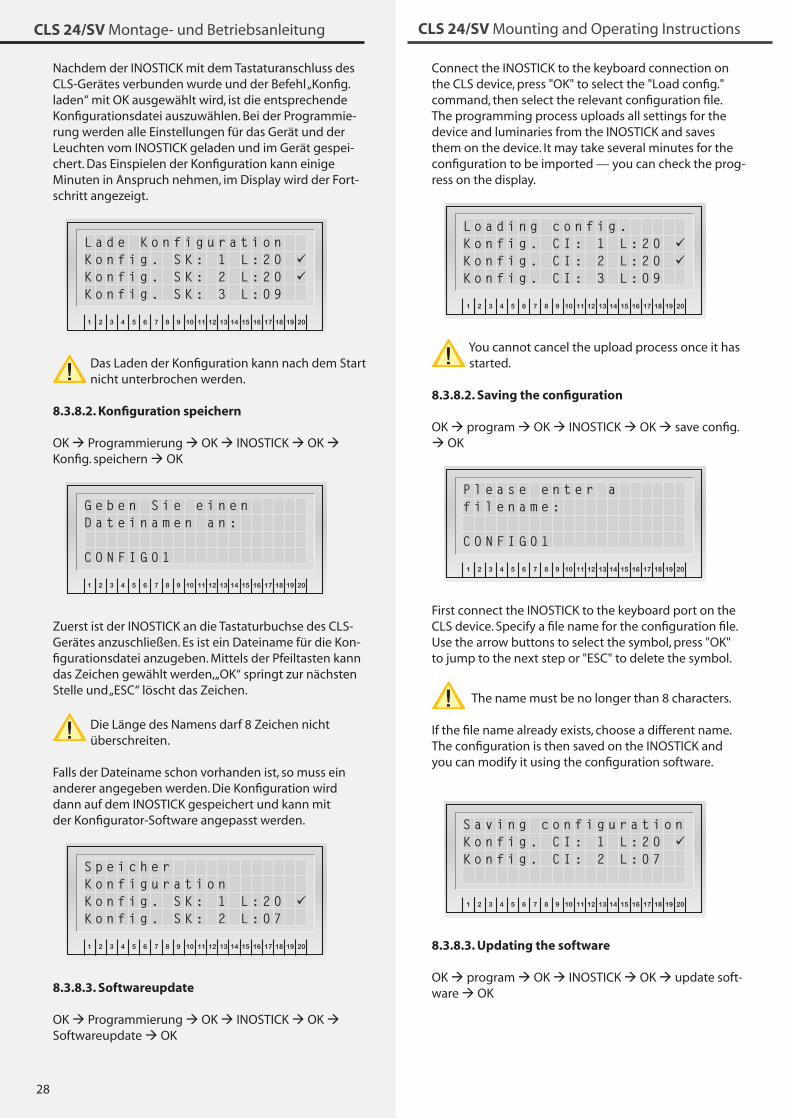
28
CLS 24/SV Montage- und Betriebsanleitung CLS 24/SV Mounting and Operating Instructions
Nachdem der INOSTICK mit dem Tastaturanschluss des CLS-Gerätes verbunden wurde und der Befehl „Konfig. laden“ mit OK ausgewählt wird, ist die entsprechende Konfigurationsdatei auszuwählen. Bei der Programmie-rung werden alle Einstellungen für das Gerät und der Leuchten vom INOSTICK geladen und im Gerät gespei-chert. Das Einspielen der Konfiguration kann einige Minuten in Anspruch nehmen, im Display wird der Fort-schritt angezeigt.
INOTEC
1 2 3 4 5 6 7 8 9 10 11 12 13 14 15 16 17 18 19 20
OK
ESC
L a d e K o n f i g u r a t i o nK o n f i g . S K : 1 L : 2 0 K o n f i g . S K : 2 L : 2 0 K o n f i g . S K : 3 L : 0 9
Das Laden der Konfiguration kann nach dem Start nicht unterbrochen werden.
8.3.8.2. Konfiguration speichern
OK Programmierung OK INOSTICK OK Konfig. speichern OK
INOTEC
1 2 3 4 5 6 7 8 9 10 11 12 13 14 15 16 17 18 19 20
OK
ESC
G e b e n S i e e i n e n D a t e i n a m e n a n :
C O N F I G 0 1
Zuerst ist der INOSTICK an die Tastaturbuchse des CLS-Gerätes anzuschließen. Es ist ein Dateiname für die Kon-figurationsdatei anzugeben. Mittels der Pfeiltasten kann das Zeichen gewählt werden, „OK“ springt zur nächsten Stelle und „ESC“ löscht das Zeichen.
Die Länge des Namens darf 8 Zeichen nicht überschreiten.
Falls der Dateiname schon vorhanden ist, so muss ein anderer angegeben werden. Die Konfiguration wird dann auf dem INOSTICK gespeichert und kann mit der Konfigurator-Software angepasst werden.
INOTEC
1 2 3 4 5 6 7 8 9 10 11 12 13 14 15 16 17 18 19 20
OK
ESC
S p e i c h e r K o n f i g u r a t i o nK o n f i g . S K : 1 L : 2 0 K o n f i g . S K : 2 L : 0 7
8.3.8.3. Softwareupdate
OK Programmierung OK INOSTICK OK Softwareupdate OK
Connect the INOSTICK to the keyboard connection on the CLS device, press "OK" to select the "Load config." command, then select the relevant configuration file. The programming process uploads all settings for the device and luminaries from the INOSTICK and saves them on the device. It may take several minutes for the configuration to be imported — you can check the prog-ress on the display.
INOTEC
1 2 3 4 5 6 7 8 9 10 11 12 13 14 15 16 17 18 19 20
OK
ESC
L o a d i n g c o n f i g .K o n f i g . C I : 1 L : 2 0 K o n f i g . C I : 2 L : 2 0 K o n f i g . C I : 3 L : 0 9
You cannot cancel the upload process once it has started.
8.3.8.2. Saving the configuration
OK program OK INOSTICK OK save config. OK
INOTEC
1 2 3 4 5 6 7 8 9 10 11 12 13 14 15 16 17 18 19 20
OK
ESC
P l e a s e e n t e r a f i l e n a m e :
C O N F I G 0 1
First connect the INOSTICK to the keyboard port on the CLS device. Specify a file name for the configuration file. Use the arrow buttons to select the symbol, press "OK" to jump to the next step or "ESC" to delete the symbol.
The name must be no longer than 8 characters.
If the file name already exists, choose a different name. The configuration is then saved on the INOSTICK and you can modify it using the configuration software.
INOTEC
1 2 3 4 5 6 7 8 9 10 11 12 13 14 15 16 17 18 19 20
OK
ESC
S a v i n g c o n f i g u r a t i o nK o n f i g . C I : 1 L : 2 0 K o n f i g . C I : 2 L : 0 7
8.3.8.3. Updating the software
OK program OK INOSTICK OK update soft-ware OK
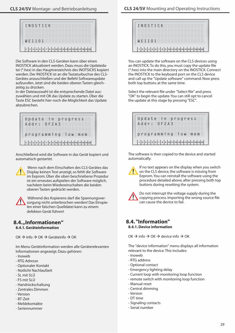
29
CLS 24/SV Montage- und Betriebsanleitung CLS 24/SV Mounting and Operating Instructions
INOTEC
1 2 3 4 5 6 7 8 9 10 11 12 13 14 15 16 17 18 19 20
OK
ESC
I N O S T I C K
W E 1 1 0 1
You can update the software on the CLS devices using an INOSTICK. To do this, you must copy the update file (*.hex) into the main directory on the INOSTICK. Connect the INOSTICK to the keyboard port on the CLS device and call up the "Update software" command. Now press both top buttons at the same time.
Select the relevant file under "Select file" and press "OK" to begin the update. You can still opt to cancel the update at this stage by pressing "ESC".
INOTEC
1 2 3 4 5 6 7 8 9 10 11 12 13 14 15 16 17 18 19 20
OK
ESC
U p d a t e i n p r o g r e s sA d d r : 0 F 2 A 3
p r o g r a m m i n g l o w m e m
The software is then copied to the device and started automatically.
If no text appears on the display when you switch on the CLS device, the software is missing from Eeprom. You can reinstall the software using the procedure detailed above, after pressing both top buttons during resetting the system.
Do not interrupt the voltage supply during the copying process. Importing the wrong source file can cause the device to fail.
8.4. "Information"8.4.1. Device information
OK info OK device info OK
The "device information" menu displays all information relevant to the device. This includes:- Inoweb- RTG address- Optional contact- Emergency lighting delay- Current loop with monitoring loop function - remote switch with monitoring loop function- Manual reset- Central dimming- Version- DT time- Signaling contacts - Serial number
INOTEC
1 2 3 4 5 6 7 8 9 10 11 12 13 14 15 16 17 18 19 20
OK
ESC
I N O S T I C K
W E 1 1 0 1
Die Software in den CLS-Geräten kann über einen INOSTICK aktualisiert werden. Dazu muss die Updateda-tei (*.hex) in das Hauptverzeichnis des INOTSICKS kopiert werden. Der INOSTICK ist an die Tastaturbuchse des CLS-Gerätes anzuschließen und der Befehl Softwareupdate aufzurufen. Jetzt sind die beiden oberen Tasten gleich-zeitig zu drücken. In der Dateiauswahl ist die entsprechende Datei aus-zuwählen und mit OK das Update zu starten. Über die Taste ESC besteht hier noch die Möglichkeit das Update abzubrechen.
INOTEC
1 2 3 4 5 6 7 8 9 10 11 12 13 14 15 16 17 18 19 20
OK
ESC
U p d a t e i n p r o g r e s sA d d r : 0 F 2 A 3
p r o g r a m m i n g l o w m e m
Anschließend wird die Software in das Gerät kopiert und automatisch gestartet.
Wenn nach dem Einschalten des CLS-Gerätes das Display keinen Text anzeigt, so fehlt die Software im Eeprom. Über die oben beschriebene Prozedur ist ein erneutes aufspielen der Software möglich, nachdem beim Wiedereinschalten die beiden oberen Tasten gedrückt werden.
Während des Kopierens darf die Spannungsver-sorgung nicht unterbrochen werden! Das Einspie-len einer falschen Quelldatei kann zu einem defekten Gerät führen!
8.4. „Informationen“8.4.1. Geräteinformation
OK Info OK Geräteinfo OK
Im Menu Gerätinformation werden alle Geräterelevanten Informationen angezeigt. Dazu gehören:- Inoweb - RTG Adresse- Optionaler Kontakt- Notlicht Nachlaufzeit- SL mit SLÜ- FS mit SLÜ- Handrückschaltung- Zentrales Dimmen- Version- BT-Zeit- Meldekontakte - Seriennummer
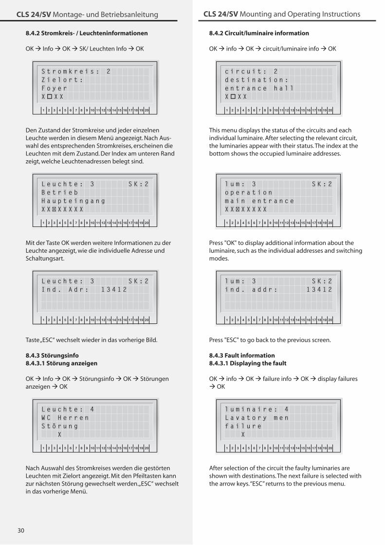
�0
CLS 24/SV Montage- und Betriebsanleitung CLS 24/SV Mounting and Operating Instructions
8.4.2 Circuit/luminaire information
OK info OK circuit/luminaire info OKINOTEC
1 2 3 4 5 6 7 8 9 10 11 12 13 14 15 16 17 18 19 20
OK
ESC
c i r c u i t : 2d e s t i n a t i o n :e n t r a n c e h a l lX X X
This menu displays the status of the circuits and each individual luminaire. After selecting the relevant circuit, the luminaries appear with their status. The index at the bottom shows the occupied luminaire addresses.
INOTEC
1 2 3 4 5 6 7 8 9 10 11 12 13 14 15 16 17 18 19 20
OK
ESC
l u m : 3 S K : 2o p e r a t i o nm a i n e n t r a n c eX X X X X X X
Press "OK" to display additional information about the luminaire, such as the individual addresses and switching modes. INOTEC
1 2 3 4 5 6 7 8 9 10 11 12 13 14 15 16 17 18 19 20
OK
ESC
l u m : 3 S K : 2i n d . a d d r : 1 3 4 1 2
Press "ESC" to go back to the previous screen.
8.4.3 Fault information8.4.3.1 Displaying the fault
OK info OK failure info OK display failures OK
INOTEC
1 2 3 4 5 6 7 8 9 10 11 12 13 14 15 16 17 18 19 20
OK
ESC
l u m i n a i r e : 4L a v a t o r y m e nf a i l u r e X
After selection of the circuit the faulty luminaries are shown with destinations. The next failure is selected with the arrow keys. “ESC” returns to the previous menu.
8.4.2 Stromkreis- / Leuchteninformationen
OK Info OK SK/ Leuchten Info OKINOTEC
1 2 3 4 5 6 7 8 9 10 11 12 13 14 15 16 17 18 19 20
OK
ESC
S t r o m k r e i s : 2Z i e l o r t :F o y e rX X X
Den Zustand der Stromkreise und jeder einzelnen Leuchte werden in diesem Menü angezeigt. Nach Aus-wahl des entsprechenden Stromkreises, erscheinen die Leuchten mit dem Zustand. Der Index am unteren Rand zeigt, welche Leuchtenadressen belegt sind.
INOTEC
1 2 3 4 5 6 7 8 9 10 11 12 13 14 15 16 17 18 19 20
OK
ESC
L e u c h t e : 3 S K : 2B e t r i e bH a u p t e i n g a n gX X X X X X X
Mit der Taste OK werden weitere Informationen zu der Leuchte angezeigt, wie die individuelle Adresse und Schaltungsart. INOTEC
1 2 3 4 5 6 7 8 9 10 11 12 13 14 15 16 17 18 19 20
OK
ESC
L e u c h t e : 3 S K : 2I n d . A d r : 1 3 4 1 2
Taste „ESC“ wechselt wieder in das vorherige Bild.
8.4.3 Störungsinfo8.4.3.1 Störung anzeigen
OK Info OK Störungsinfo OK Störungen anzeigen OK
INOTEC
1 2 3 4 5 6 7 8 9 10 11 12 13 14 15 16 17 18 19 20
OK
ESC
L e u c h t e : 4W C H e r r e nS t ö r u n g X
Nach Auswahl des Stromkreises werden die gestörten Leuchten mit Zielort angezeigt. Mit den Pfeiltasten kann zur nächsten Störung gewechselt werden. „ESC“ wechselt in das vorherige Menü.
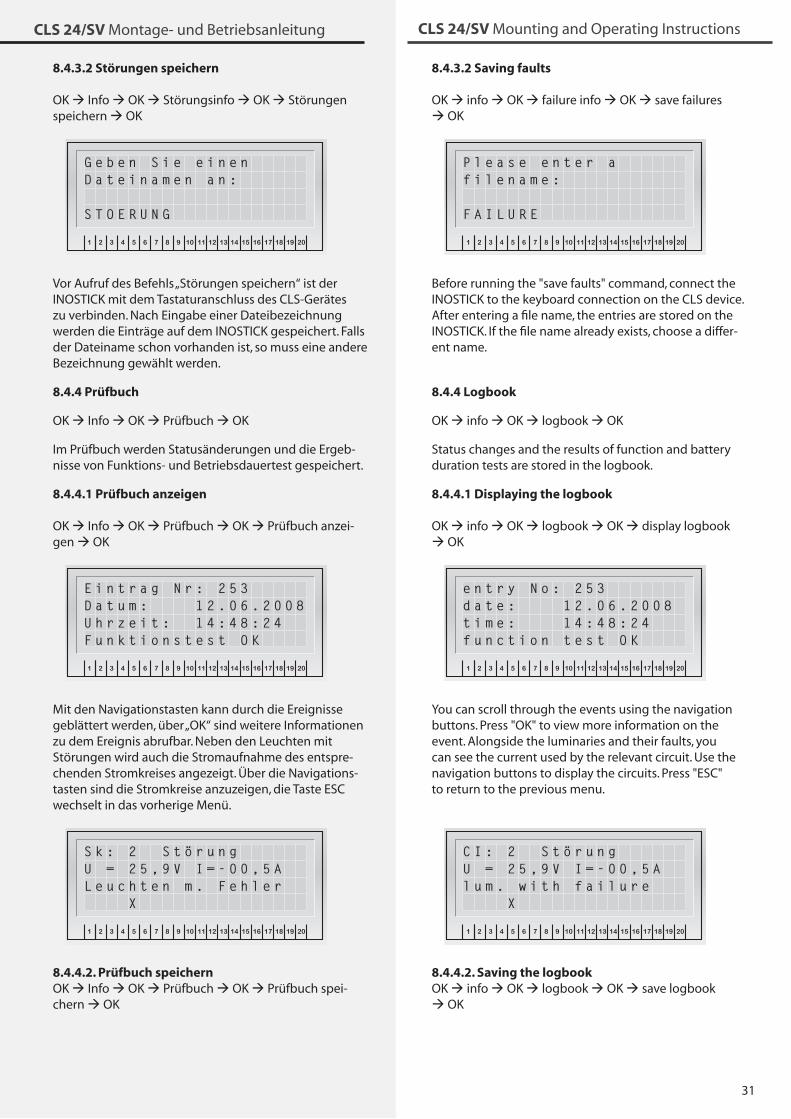
�1
CLS 24/SV Montage- und Betriebsanleitung CLS 24/SV Mounting and Operating Instructions
8.4.3.2 Saving faults
OK info OK failure info OK save failures OK
INOTEC
1 2 3 4 5 6 7 8 9 10 11 12 13 14 15 16 17 18 19 20
OK
ESC
P l e a s e e n t e r a f i l e n a m e :
F A I L U R E
Before running the "save faults" command, connect the INOSTICK to the keyboard connection on the CLS device. After entering a file name, the entries are stored on the INOSTICK. If the file name already exists, choose a differ-ent name.
8.4.4 Logbook
OK info OK logbook OK
Status changes and the results of function and battery duration tests are stored in the logbook.
8.4.4.1 Displaying the logbook
OK info OK logbook OK display logbook OK
INOTEC
1 2 3 4 5 6 7 8 9 10 11 12 13 14 15 16 17 18 19 20
OK
ESC
e n t r y N o : 2 5 3d a t e : 1 2 . 0 6 . 2 0 0 8t i m e : 1 4 : 4 8 : 2 4f u n c t i o n t e s t O K
You can scroll through the events using the navigation buttons. Press "OK" to view more information on the event. Alongside the luminaries and their faults, you can see the current used by the relevant circuit. Use the navigation buttons to display the circuits. Press "ESC" to return to the previous menu.
INOTEC
1 2 3 4 5 6 7 8 9 10 11 12 13 14 15 16 17 18 19 20
OK
ESC
C I : 2 S t ö r u n gU = 2 5 , 9 V I = - 0 0 , 5 Al u m . w i t h f a i l u r e X
8.4.4.2. Saving the logbookOK info OK logbook OK save logbook OK
8.4.3.2 Störungen speichern
OK Info OK Störungsinfo OK Störungen speichern OK
INOTEC
1 2 3 4 5 6 7 8 9 10 11 12 13 14 15 16 17 18 19 20
OK
ESC
G e b e n S i e e i n e n D a t e i n a m e n a n :
S T O E R U N G
Vor Aufruf des Befehls „Störungen speichern“ ist der INOSTICK mit dem Tastaturanschluss des CLS-Gerätes zu verbinden. Nach Eingabe einer Dateibezeichnung werden die Einträge auf dem INOSTICK gespeichert. Falls der Dateiname schon vorhanden ist, so muss eine andere Bezeichnung gewählt werden.
8.4.4 Prüfbuch
OK Info OK Prüfbuch OK
Im Prüfbuch werden Statusänderungen und die Ergeb-nisse von Funktions- und Betriebsdauertest gespeichert.
8.4.4.1 Prüfbuch anzeigen
OK Info OK Prüfbuch OK Prüfbuch anzei-gen OK
INOTEC
1 2 3 4 5 6 7 8 9 10 11 12 13 14 15 16 17 18 19 20
OK
ESC
E i n t r a g N r : 2 5 3D a t u m : 1 2 . 0 6 . 2 0 0 8U h r z e i t : 1 4 : 4 8 : 2 4F u n k t i o n s t e s t O K
Mit den Navigationstasten kann durch die Ereignisse geblättert werden, über „OK“ sind weitere Informationen zu dem Ereignis abrufbar. Neben den Leuchten mit Störungen wird auch die Stromaufnahme des entspre-chenden Stromkreises angezeigt. Über die Navigations-tasten sind die Stromkreise anzuzeigen, die Taste ESC wechselt in das vorherige Menü.
INOTEC
1 2 3 4 5 6 7 8 9 10 11 12 13 14 15 16 17 18 19 20
OK
ESC
S k : 2 S t ö r u n gU = 2 5 , 9 V I = - 0 0 , 5 AL e u c h t e n m . F e h l e r X
8.4.4.2. Prüfbuch speichernOK Info OK Prüfbuch OK Prüfbuch spei-chern OK
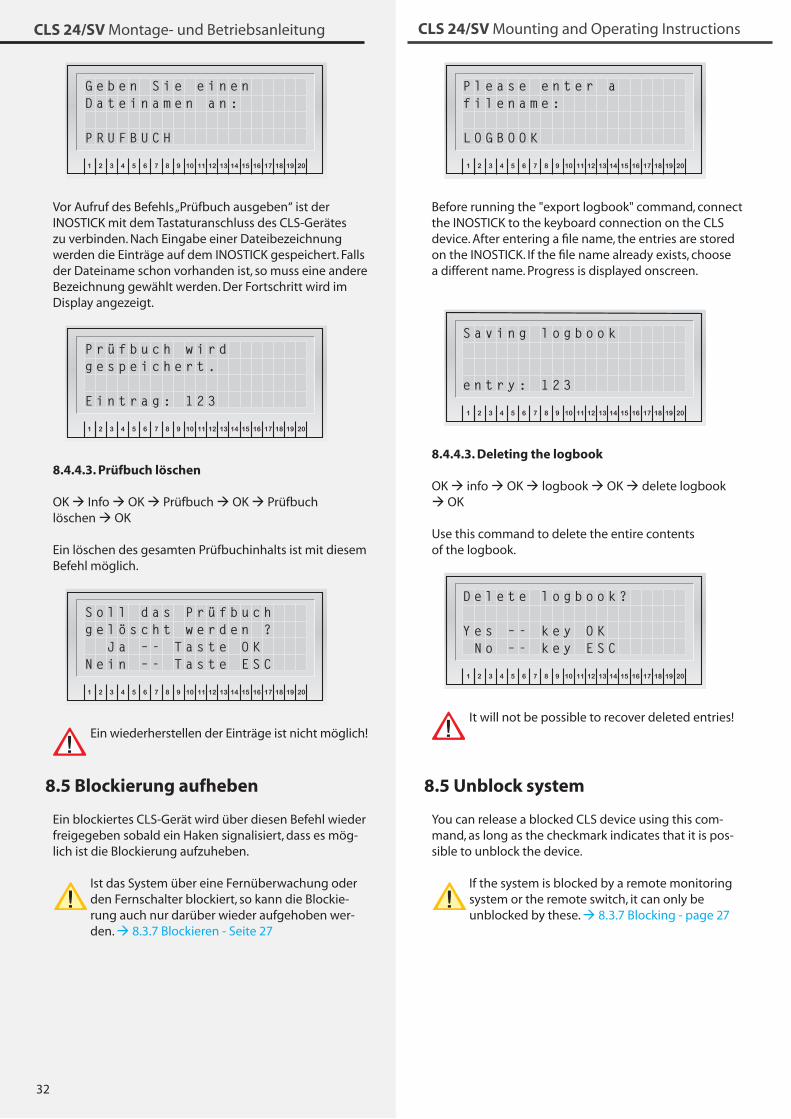
�2
CLS 24/SV Montage- und Betriebsanleitung CLS 24/SV Mounting and Operating Instructions
INOTEC
1 2 3 4 5 6 7 8 9 10 11 12 13 14 15 16 17 18 19 20
OK
ESC
P l e a s e e n t e r a f i l e n a m e :
L O G B O O K
Before running the "export logbook" command, connect the INOSTICK to the keyboard connection on the CLS device. After entering a file name, the entries are stored on the INOSTICK. If the file name already exists, choose a different name. Progress is displayed onscreen.
INOTEC
1 2 3 4 5 6 7 8 9 10 11 12 13 14 15 16 17 18 19 20
OK
ESC
S a v i n g l o g b o o k
e n t r y : 1 2 3
8.4.4.3. Deleting the logbook
OK info OK logbook OK delete logbook OK
Use this command to delete the entire contents of the logbook.
INOTEC
1 2 3 4 5 6 7 8 9 10 11 12 13 14 15 16 17 18 19 20
OK
ESC
D e l e t e l o g b o o k ? Y e s – - k e y O K N o – - k e y E S C
It will not be possible to recover deleted entries!
8.5 Unblock system
You can release a blocked CLS device using this com-mand, as long as the checkmark indicates that it is pos-sible to unblock the device.
If the system is blocked by a remote monitoring system or the remote switch, it can only be unblocked by these. 8.�.7 Blocking - page 27
INOTEC
1 2 3 4 5 6 7 8 9 10 11 12 13 14 15 16 17 18 19 20
OK
ESC
G e b e n S i e e i n e n D a t e i n a m e n a n :
P R U F B U C H
Vor Aufruf des Befehls „Prüfbuch ausgeben“ ist der INOSTICK mit dem Tastaturanschluss des CLS-Gerätes zu verbinden. Nach Eingabe einer Dateibezeichnung werden die Einträge auf dem INOSTICK gespeichert. Falls der Dateiname schon vorhanden ist, so muss eine andere Bezeichnung gewählt werden. Der Fortschritt wird im Display angezeigt.
INOTEC
1 2 3 4 5 6 7 8 9 10 11 12 13 14 15 16 17 18 19 20
OK
ESC
P r ü f b u c h w i r d g e s p e i c h e r t .
E i n t r a g : 1 2 3
8.4.4.3. Prüfbuch löschen
OK Info OK Prüfbuch OK Prüfbuch löschen OK
Ein löschen des gesamten Prüfbuchinhalts ist mit diesem Befehl möglich.
INOTEC
1 2 3 4 5 6 7 8 9 10 11 12 13 14 15 16 17 18 19 20
OK
ESC
S o l l d a s P r ü f b u c hg e l ö s c h t w e r d e n ? J a – - T a s t e O KN e i n – - T a s t e E S C
Ein wiederherstellen der Einträge ist nicht möglich!
8.5 Blockierung aufheben
Ein blockiertes CLS-Gerät wird über diesen Befehl wieder freigegeben sobald ein Haken signalisiert, dass es mög-lich ist die Blockierung aufzuheben.
Ist das System über eine Fernüberwachung oder den Fernschalter blockiert, so kann die Blockie-rung auch nur darüber wieder aufgehoben wer-den. 8.�.7 Blockieren - Seite 27
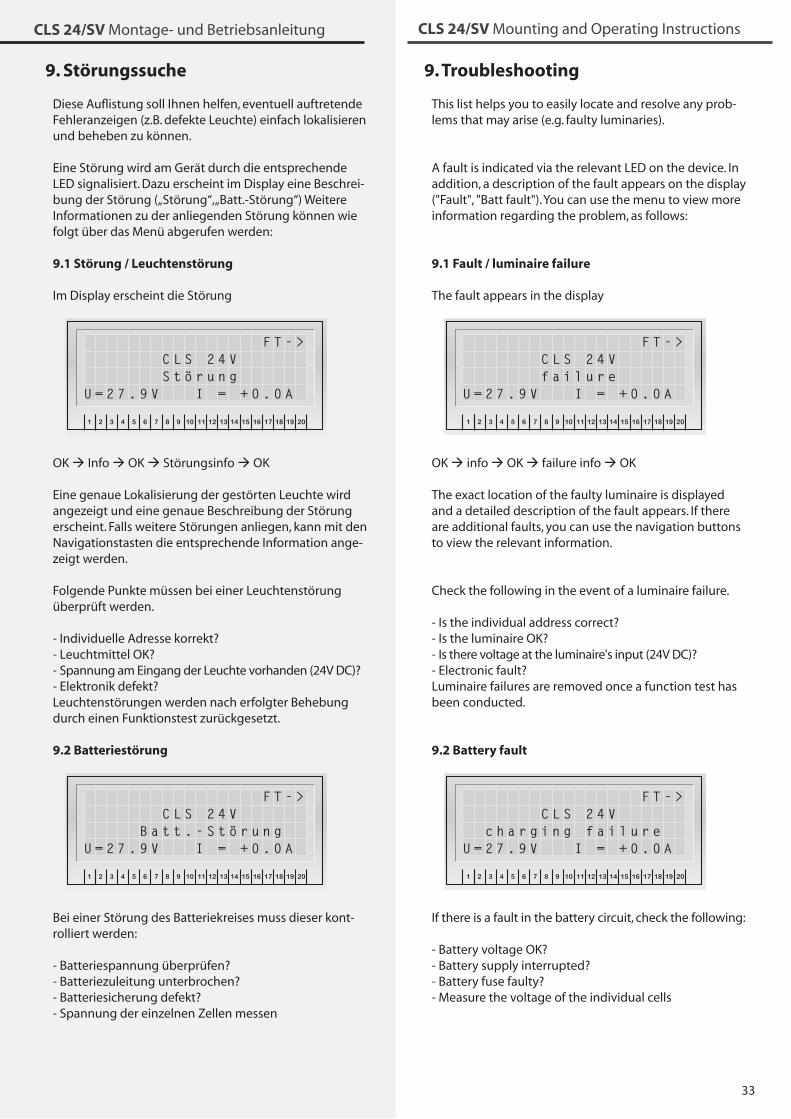
��
CLS 24/SV Montage- und Betriebsanleitung CLS 24/SV Mounting and Operating Instructions
9. Störungssuche
Diese Auflistung soll Ihnen helfen, eventuell auftretende Fehleranzeigen (z.B. defekte Leuchte) einfach lokalisieren und beheben zu können.
Eine Störung wird am Gerät durch die entsprechende LED signalisiert. Dazu erscheint im Display eine Beschrei-bung der Störung („Störung“, „Batt.-Störung“) Weitere Informationen zu der anliegenden Störung können wie folgt über das Menü abgerufen werden:
9.1 Störung / Leuchtenstörung
Im Display erscheint die StörungINOTEC
1 2 3 4 5 6 7 8 9 10 11 12 13 14 15 16 17 18 19 20
OK
ESC
F T - > C L S 2 4 V S t ö r u n gU = 2 7 . 9 V I = + 0 . 0 A
OK Info OK Störungsinfo OK
Eine genaue Lokalisierung der gestörten Leuchte wird angezeigt und eine genaue Beschreibung der Störung erscheint. Falls weitere Störungen anliegen, kann mit den Navigationstasten die entsprechende Information ange-zeigt werden.
Folgende Punkte müssen bei einer Leuchtenstörung überprüft werden.
- Individuelle Adresse korrekt?- Leuchtmittel OK?- Spannung am Eingang der Leuchte vorhanden (24V DC)?- Elektronik defekt?Leuchtenstörungen werden nach erfolgter Behebung durch einen Funktionstest zurückgesetzt.
9.2 BatteriestörungINOTEC
1 2 3 4 5 6 7 8 9 10 11 12 13 14 15 16 17 18 19 20
OK
ESC
F T - > C L S 2 4 V B a t t . - S t ö r u n gU = 2 7 . 9 V I = + 0 . 0 A
Bei einer Störung des Batteriekreises muss dieser kont-rolliert werden:
- Batteriespannung überprüfen?- Batteriezuleitung unterbrochen?- Batteriesicherung defekt?- Spannung der einzelnen Zellen messen
9. Troubleshooting
This list helps you to easily locate and resolve any prob-lems that may arise (e.g. faulty luminaries).
A fault is indicated via the relevant LED on the device. In addition, a description of the fault appears on the display ("Fault", "Batt fault"). You can use the menu to view more information regarding the problem, as follows:
9.1 Fault / luminaire failure
The fault appears in the displayINOTEC
1 2 3 4 5 6 7 8 9 10 11 12 13 14 15 16 17 18 19 20
OK
ESC
F T - > C L S 2 4 V f a i l u r eU = 2 7 . 9 V I = + 0 . 0 A
OK info OK failure info OK
The exact location of the faulty luminaire is displayed and a detailed description of the fault appears. If there are additional faults, you can use the navigation buttons to view the relevant information.
Check the following in the event of a luminaire failure.
- Is the individual address correct?- Is the luminaire OK?- Is there voltage at the luminaire's input (24V DC)?- Electronic fault?Luminaire failures are removed once a function test has been conducted.
9.2 Battery faultINOTEC
1 2 3 4 5 6 7 8 9 10 11 12 13 14 15 16 17 18 19 20
OK
ESC
F T - > C L S 2 4 V c h a r g i n g f a i l u r eU = 2 7 . 9 V I = + 0 . 0 A
If there is a fault in the battery circuit, check the following:
- Battery voltage OK?- Battery supply interrupted?- Battery fuse faulty?- Measure the voltage of the individual cells
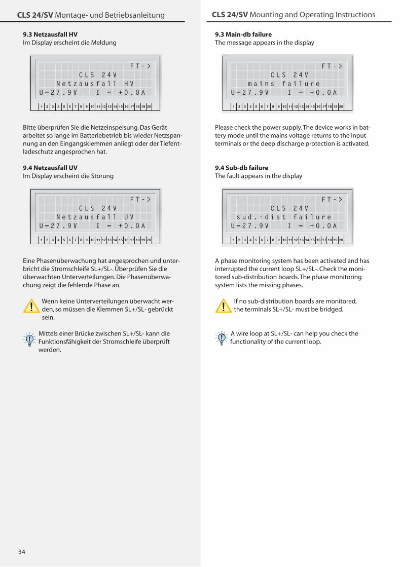
�4
CLS 24/SV Montage- und Betriebsanleitung CLS 24/SV Mounting and Operating Instructions
9.3 Netzausfall HVIm Display erscheint die Meldung
INOTEC
1 2 3 4 5 6 7 8 9 10 11 12 13 14 15 16 17 18 19 20
OK
ESC
F T - > C L S 2 4 V N e t z a u s f a l l H VU = 2 7 . 9 V I = + 0 . 0 A
Bitte überprüfen Sie die Netzeinspeisung. Das Gerät arbeitet so lange im Batteriebetrieb bis wieder Netzspan-nung an den Eingangsklemmen anliegt oder der Tiefent-ladeschutz angesprochen hat.
9.4 Netzausfall UVIm Display erscheint die Störung
INOTEC
1 2 3 4 5 6 7 8 9 10 11 12 13 14 15 16 17 18 19 20
OK
ESC
F T - > C L S 2 4 V N e t z a u s f a l l U VU = 2 7 . 9 V I = + 0 . 0 A
Eine Phasenüberwachung hat angesprochen und unter-bricht die Stromschleife SL+/SL-. Überprüfen Sie die überwachten Unterverteilungen. Die Phasenüberwa-chung zeigt die fehlende Phase an.
Wenn keine Unterverteilungen überwacht wer-den, so müssen die Klemmen SL+/SL- gebrückt sein.
Mittels einer Brücke zwischen SL+/SL- kann die Funktionsfähigkeit der Stromschleife überprüft werden.
9.3 Main-db failureThe message appears in the display
INOTEC
1 2 3 4 5 6 7 8 9 10 11 12 13 14 15 16 17 18 19 20
OK
ESC
F T - > C L S 2 4 V m a i n s f a i l u r eU = 2 7 . 9 V I = + 0 . 0 A
Please check the power supply. The device works in bat-tery mode until the mains voltage returns to the input terminals or the deep discharge protection is activated.
9.4 Sub-db failureThe fault appears in the display
INOTEC
1 2 3 4 5 6 7 8 9 10 11 12 13 14 15 16 17 18 19 20
OK
ESC
F T - > C L S 2 4 V s u d . - d i s t f a i l u r eU = 2 7 . 9 V I = + 0 . 0 A
A phase monitoring system has been activated and has interrupted the current loop SL+/SL-. Check the moni-tored sub-distribution boards. The phase monitoring system lists the missing phases.
If no sub-distribution boards are monitored, the terminals SL+/SL- must be bridged.
A wire loop at SL+/SL- can help you check the functionality of the current loop.
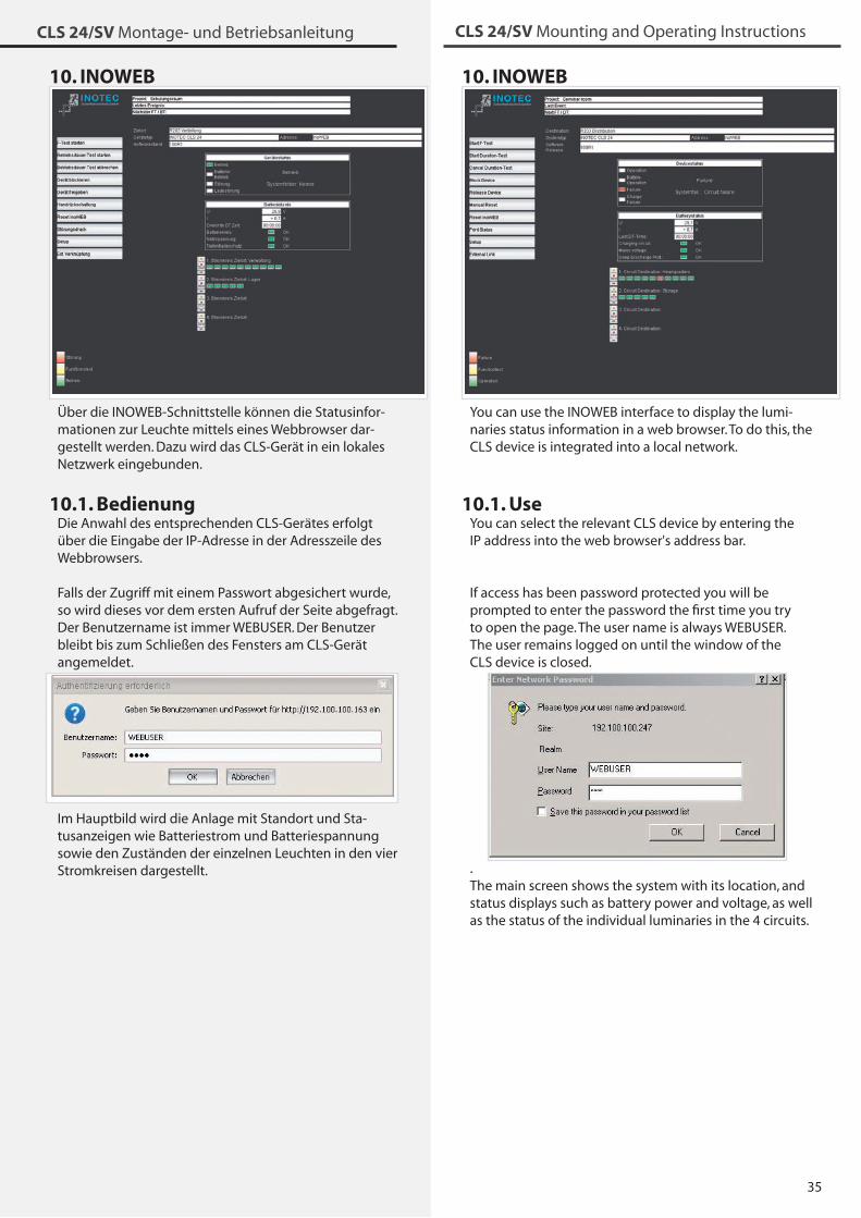
�5
CLS 24/SV Montage- und Betriebsanleitung CLS 24/SV Mounting and Operating Instructions
10. INOWEB
Über die INOWEB-Schnittstelle können die Statusinfor-mationen zur Leuchte mittels eines Webbrowser dar-gestellt werden. Dazu wird das CLS-Gerät in ein lokales Netzwerk eingebunden.
10.1. BedienungDie Anwahl des entsprechenden CLS-Gerätes erfolgt über die Eingabe der IP-Adresse in der Adresszeile des Webbrowsers.
Falls der Zugriff mit einem Passwort abgesichert wurde, so wird dieses vor dem ersten Aufruf der Seite abgefragt. Der Benutzername ist immer WEBUSER. Der Benutzer bleibt bis zum Schließen des Fensters am CLS-Gerät angemeldet..
Im Hauptbild wird die Anlage mit Standort und Sta-tusanzeigen wie Batteriestrom und Batteriespannung sowie den Zuständen der einzelnen Leuchten in den vier Stromkreisen dargestellt.
10. INOWEB
You can use the INOWEB interface to display the lumi-naries status information in a web browser. To do this, the CLS device is integrated into a local network.
10.1. UseYou can select the relevant CLS device by entering the IP address into the web browser's address bar.
If access has been password protected you will be prompted to enter the password the first time you try to open the page. The user name is always WEBUSER. The user remains logged on until the window of the CLS device is closed.
.The main screen shows the system with its location, and status displays such as battery power and voltage, as well as the status of the individual luminaries in the 4 circuits.
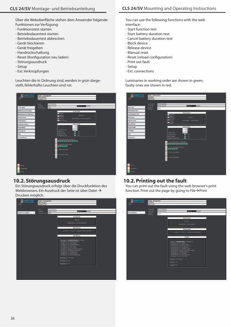
�6
CLS 24/SV Montage- und Betriebsanleitung CLS 24/SV Mounting and Operating Instructions
Über die Weboberfläche stehen dem Anwender folgende Funktionen zur Verfügung:- Funktionstest starten- Betriebsdauertest starten- Betriebsdauertest abbrechen- Gerät blockieren- Gerät freigeben- Handrückschaltung- Reset (Konfiguration neu laden)- Störungsausdruck- Setup- Ext. Verknüpfungen
Leuchten die in Ordnung sind, werden in grün darge-stellt, fehlerhafte Leuchten sind rot.
10.2. StörungsausdruckEin Störungsausdruck erfolgt über die Druckfunktion des Webbrowsers. Ein Ausdruck der Seite ist über Datei Drucken möglich.
You can use the following functions with the web interface:- Start function test- Start battery duration test- Cancel battery duration test- Block device- Release device- Manual reset- Reset (reload configuration)- Print out fault- Setup- Ext. connections
Luminaries in working order are shown in green, faulty ones are shown in red.
10.2. Printing out the faultYou can print out the fault using the web browser's print function. Print out the page by going to FilePrint
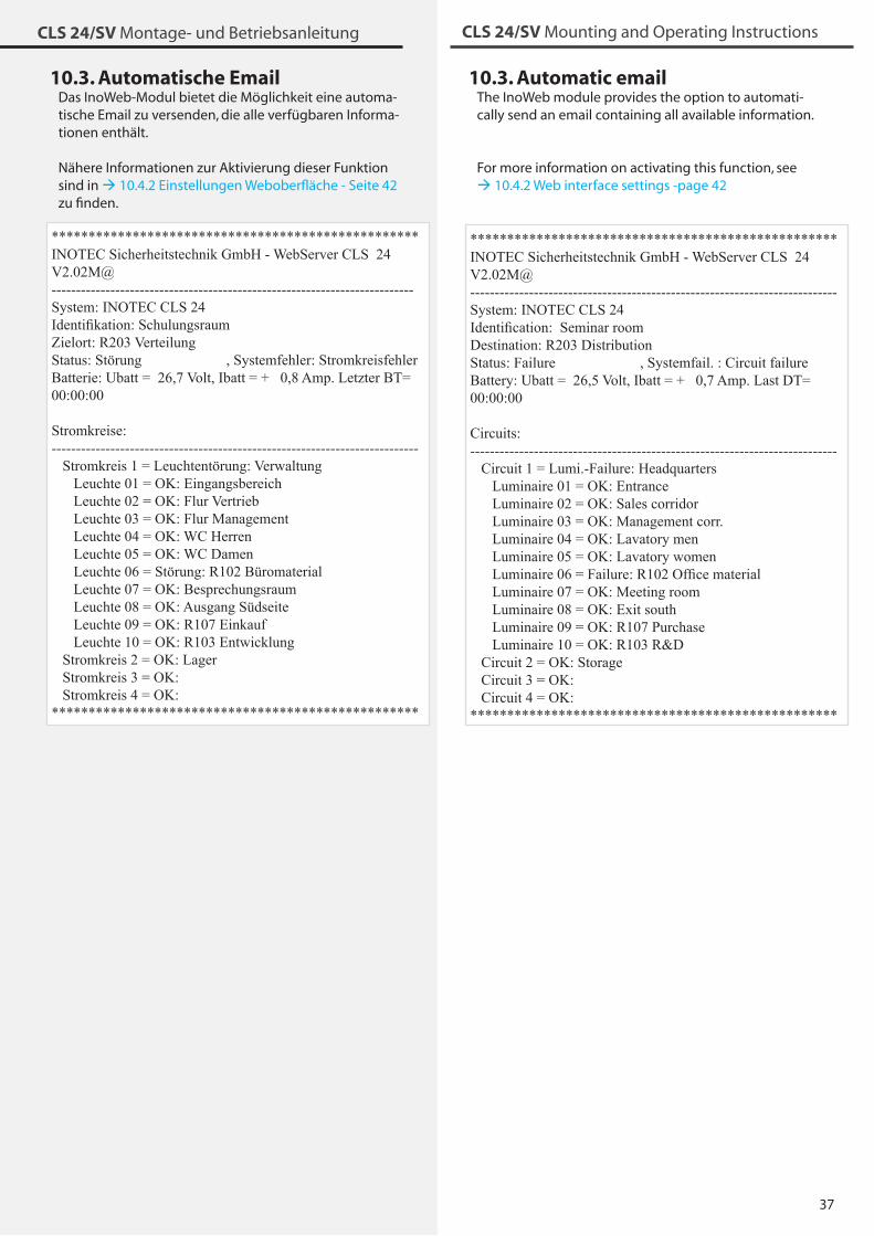
�7
CLS 24/SV Montage- und Betriebsanleitung CLS 24/SV Mounting and Operating Instructions
10.3. Automatische EmailDas InoWeb-Modul bietet die Möglichkeit eine automa-tische Email zu versenden, die alle verfügbaren Informa-tionen enthält.
Nähere Informationen zur Aktivierung dieser Funktion sind in 10.4.2 Einstellungen Weboberfläche - Seite 42 zu finden.
**************************************************INOTEC Sicherheitstechnik GmbH - WebServer CLS 24 V2.02M@--------------------------------------------------------------------------System: INOTEC CLS 24 Identifikation: SchulungsraumZielort: R203 Verteilung Status: Störung , Systemfehler: StromkreisfehlerBatterie: Ubatt = 26,7 Volt, Ibatt = + 0,8 Amp. Letzter BT= 00:00:00
Stromkreise:--------------------------------------------------------------------------- Stromkreis 1 = Leuchtentörung: Verwaltung Leuchte 01 = OK: Eingangsbereich Leuchte 02 = OK: Flur Vertrieb Leuchte 03 = OK: Flur Management Leuchte 04 = OK: WC Herren Leuchte 05 = OK: WC Damen Leuchte 06 = Störung: R102 Büromaterial Leuchte 07 = OK: Besprechungsraum Leuchte 08 = OK: Ausgang Südseite Leuchte 09 = OK: R107 Einkauf Leuchte 10 = OK: R103 Entwicklung Stromkreis 2 = OK: Lager Stromkreis 3 = OK: Stromkreis 4 = OK: **************************************************
10.3. Automatic emailThe InoWeb module provides the option to automati-cally send an email containing all available information.
For more information on activating this function, see 10.4.2 Web interface settings -page 42
**************************************************INOTEC Sicherheitstechnik GmbH - WebServer CLS 24 V2.02M@---------------------------------------------------------------------------System: INOTEC CLS 24 Identification: Seminar roomDestination: R203 Distribution Status: Failure , Systemfail. : Circuit failure Battery: Ubatt = 26,5 Volt, Ibatt = + 0,7 Amp. Last DT= 00:00:00
Circuits:--------------------------------------------------------------------------- Circuit 1 = Lumi.-Failure: Headquarters Luminaire 01 = OK: Entrance Luminaire 02 = OK: Sales corridor Luminaire 03 = OK: Management corr. Luminaire 04 = OK: Lavatory men Luminaire 05 = OK: Lavatory women Luminaire 06 = Failure: R102 Office material Luminaire 07 = OK: Meeting room Luminaire 08 = OK: Exit south Luminaire 09 = OK: R107 Purchase Luminaire 10 = OK: R103 R&D Circuit 2 = OK: Storage Circuit 3 = OK: Circuit 4 = OK: **************************************************
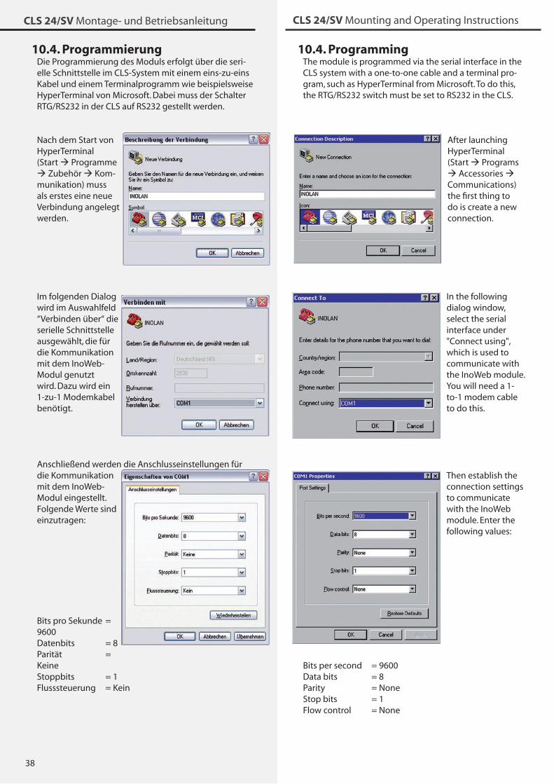
�8
CLS 24/SV Montage- und Betriebsanleitung CLS 24/SV Mounting and Operating Instructions
10.4. ProgrammingThe module is programmed via the serial interface in the CLS system with a one-to-one cable and a terminal pro-gram, such as HyperTerminal from Microsoft. To do this, the RTG/RS2�2 switch must be set to RS2�2 in the CLS.
After launching HyperTerminal (Start Programs Accessories Communications) the first thing to do is create a new connection.
In the following dialog window, select the serial interface under "Connect using", which is used to communicate with the InoWeb module. You will need a 1-to-1 modem cable to do this.
Then establish the connection settings to communicate with the InoWeb module. Enter the following values:
Bits per second = 9600Data bits = 8Parity = NoneStop bits = 1Flow control = None
10.4. ProgrammierungDie Programmierung des Moduls erfolgt über die seri-elle Schnittstelle im CLS-System mit einem eins-zu-eins Kabel und einem Terminalprogramm wie beispielsweise HyperTerminal von Microsoft. Dabei muss der Schalter RTG/RS2�2 in der CLS auf RS2�2 gestellt werden.
Nach dem Start von HyperTerminal (Start Programme Zubehör Kom-munikation) muss als erstes eine neue Verbindung angelegt werden.
Im folgenden Dialog wird im Auswahlfeld “Verbinden über“ die serielle Schnittstelle ausgewählt, die für die Kommunikation mit dem InoWeb-Modul genutzt wird. Dazu wird ein 1-zu-1 Modemkabel benötigt.
Anschließend werden die Anschlusseinstellungen für die Kommunikation mit dem InoWeb-Modul eingestellt. Folgende Werte sind einzutragen:
Bits pro Sekunde = 9600Datenbits = 8Parität = KeineStoppbits = 1Flusssteuerung = Kein
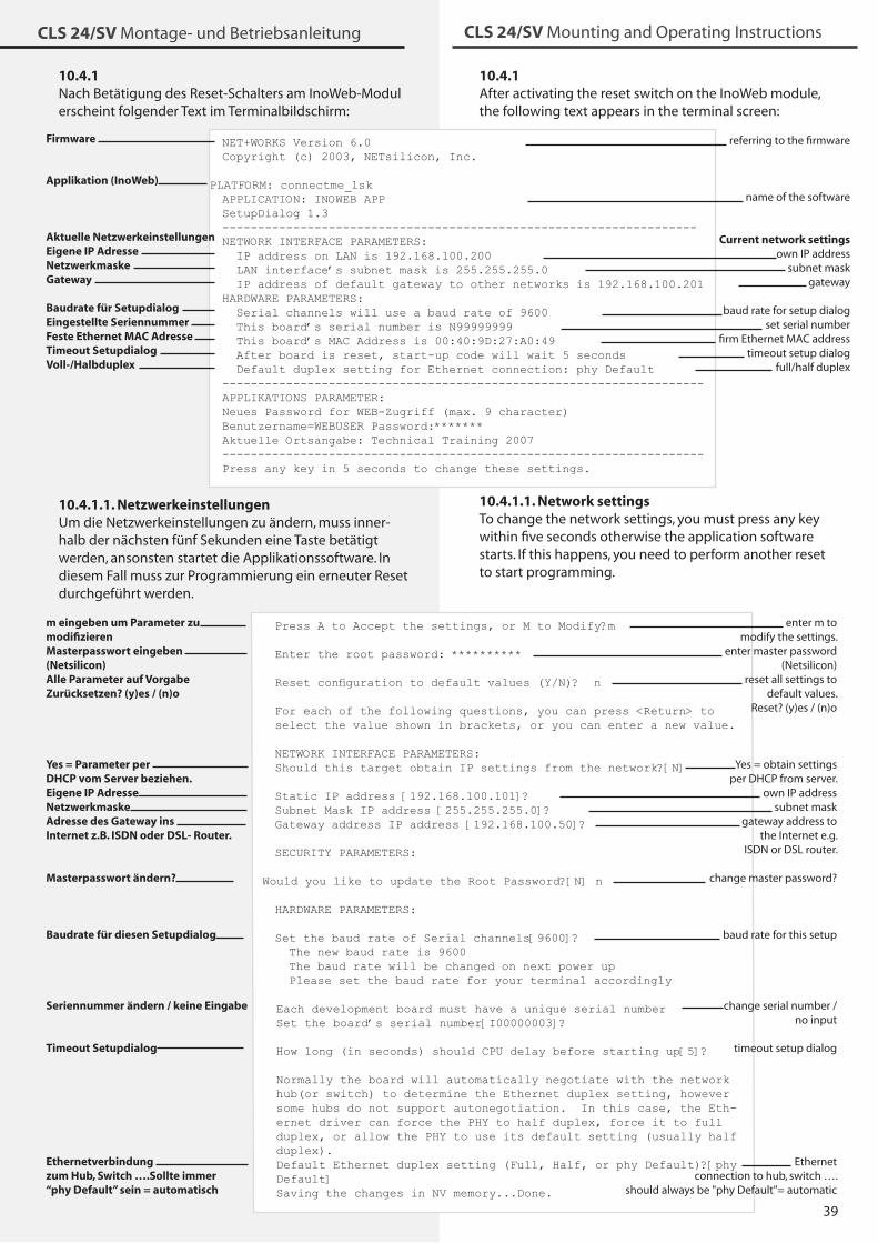
�9
CLS 24/SV Montage- und Betriebsanleitung CLS 24/SV Mounting and Operating Instructions
10.4.1After activating the reset switch on the InoWeb module, the following text appears in the terminal screen:
10.4.1.1. Network settingsTo change the network settings, you must press any key within five seconds otherwise the application software starts. If this happens, you need to perform another reset to start programming.
Press A to Accept the settings, or M to Modify?m Enter the root password: ********** Reset configuration to default values (Y/N)? n For each of the following questions, you can press <Return> to select the value shown in brackets, or you can enter a new value.
NETWORK INTERFACE PARAMETERS:Should this target obtain IP settings from the network?[N] Static IP address [192.168.100.101]? Subnet Mask IP address [255.255.255.0]? Gateway address IP address [192.168.100.50]?
SECURITY PARAMETERS:
Would you like to update the Root Password?[N] n
HARDWARE PARAMETERS:
Set the baud rate of Serial channels[9600]? The new baud rate is 9600 The baud rate will be changed on next power up Please set the baud rate for your terminal accordingly
Each development board must have a unique serial numberSet the board’s serial number[I00000003]?
How long (in seconds) should CPU delay before starting up[5]?
Normally the board will automatically negotiate with the network hub(or switch) to determine the Ethernet duplex setting, however some hubs do not support autonegotiation. In this case, the Eth-ernet driver can force the PHY to half duplex, force it to full duplex, or allow the PHY to use its default setting (usually half duplex).Default Ethernet duplex setting (Full, Half, or phy Default)?[phy Default] Saving the changes in NV memory...Done.
enter m to modify the settings.
enter master password (Netsilicon)
reset all settings to default values.
Reset? (y)es / (n)o
Yes = obtain settingsper DHCP from server.
own IP addresssubnet mask
gateway address to the Internet e.g.
ISDN or DSL router.
change master password?
baud rate for this setup
change serial number /
no input
timeout setup dialog
Ethernet connection to hub, switch ….
should always be "phy Default"= automatic
NET+WORKS Version 6.0 Copyright (c) 2003, NETsilicon, Inc.
PLATFORM: connectme_lsk APPLICATION: INOWEB APP SetupDialog 1.3-------------------------------------------------------------------NETWORK INTERFACE PARAMETERS: IP address on LAN is 192.168.100.200 LAN interface’s subnet mask is 255.255.255.0 IP address of default gateway to other networks is 192.168.100.201 HARDWARE PARAMETERS: Serial channels will use a baud rate of 9600 This board’s serial number is N99999999 This board’s MAC Address is 00:40:9D:27:A0:49 After board is reset, start-up code will wait 5 seconds Default duplex setting for Ethernet connection: phy Default --------------------------------------------------------------------APPLIKATIONS PARAMETER:Neues Password for WEB-Zugriff (max. 9 character)Benutzername=WEBUSER Password:*******Aktuelle Ortsangabe: Technical Training 2007--------------------------------------------------------------------Press any key in 5 seconds to change these settings.
10.4.1Nach Betätigung des Reset-Schalters am InoWeb-Modul erscheint folgender Text im Terminalbildschirm:
Firmware
Applikation (InoWeb)
Aktuelle NetzwerkeinstellungenEigene IP AdresseNetzwerkmaskeGateway
Baudrate für SetupdialogEingestellte SeriennummerFeste Ethernet MAC AdresseTimeout SetupdialogVoll-/Halbduplex
10.4.1.1. NetzwerkeinstellungenUm die Netzwerkeinstellungen zu ändern, muss inner-halb der nächsten fünf Sekunden eine Taste betätigt werden, ansonsten startet die Applikationssoftware. In diesem Fall muss zur Programmierung ein erneuter Reset durchgeführt werden.
m eingeben um Parameter zumodifizierenMasterpasswort eingeben (Netsilicon)Alle Parameter auf Vorgabe Zurücksetzen? (y)es / (n)o
Yes = Parameter per DHCP vom Server beziehen.Eigene IP AdresseNetzwerkmaskeAdresse des Gateway ins Internet z.B. ISDN oder DSL- Router.
Masterpasswort ändern?
Baudrate für diesen Setupdialog
Seriennummer ändern / keine Eingabe
Timeout Setupdialog
Ethernetverbindung zum Hub, Switch ….Sollte immer “phy Default” sein = automatisch
referring to the firmware
name of the software
Current network settingsown IP address
subnet maskgateway
baud rate for setup dialogset serial number
firm Ethernet MAC addresstimeout setup dialog
full/half duplex
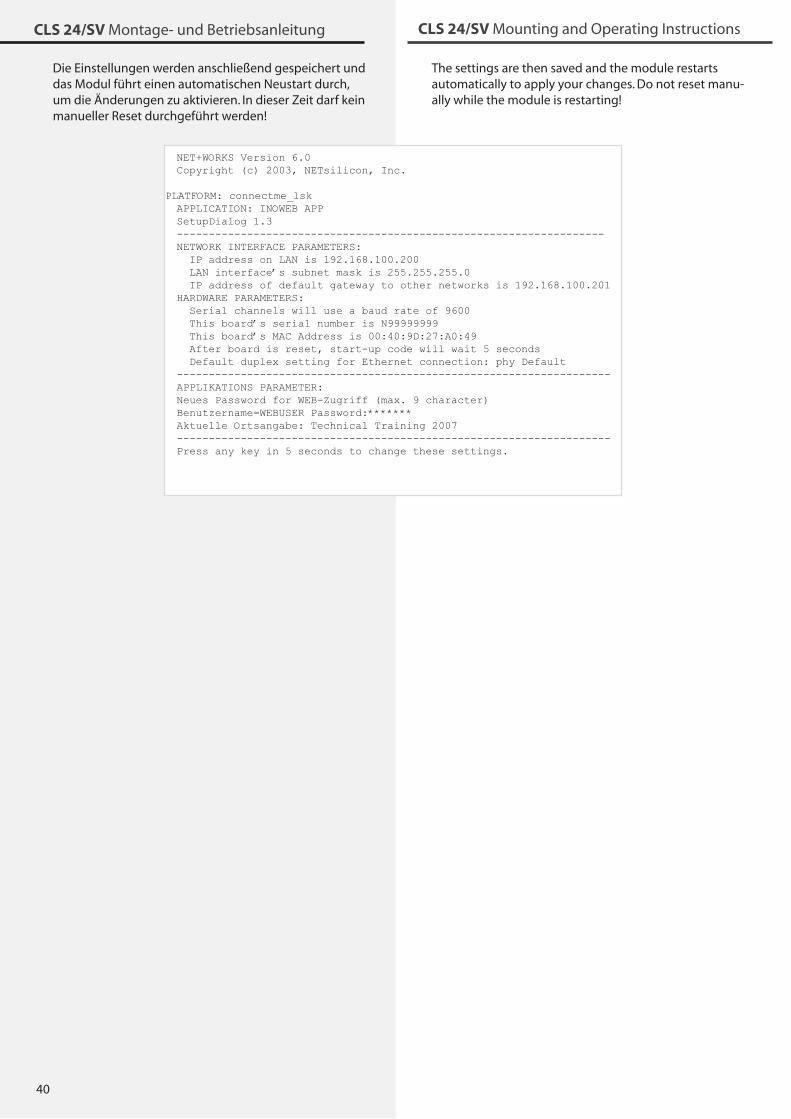
40
CLS 24/SV Montage- und Betriebsanleitung CLS 24/SV Mounting and Operating Instructions
Die Einstellungen werden anschließend gespeichert und das Modul führt einen automatischen Neustart durch, um die Änderungen zu aktivieren. In dieser Zeit darf kein manueller Reset durchgeführt werden!
The settings are then saved and the module restarts automatically to apply your changes. Do not reset manu-ally while the module is restarting!
NET+WORKS Version 6.0Copyright (c) 2003, NETsilicon, Inc.
PLATFORM: connectme_lskAPPLICATION: INOWEB APPSetupDialog 1.3-------------------------------------------------------------------NETWORK INTERFACE PARAMETERS: IP address on LAN is 192.168.100.200 LAN interface’s subnet mask is 255.255.255.0 IP address of default gateway to other networks is 192.168.100.201 HARDWARE PARAMETERS: Serial channels will use a baud rate of 9600 This board’s serial number is N99999999 This board’s MAC Address is 00:40:9D:27:A0:49 After board is reset, start-up code will wait 5 seconds Default duplex setting for Ethernet connection: phy Default--------------------------------------------------------------------APPLIKATIONS PARAMETER:Neues Password for WEB-Zugriff (max. 9 character)Benutzername=WEBUSER Password:*******Aktuelle Ortsangabe: Technical Training 2007--------------------------------------------------------------------Press any key in 5 seconds to change these settings.
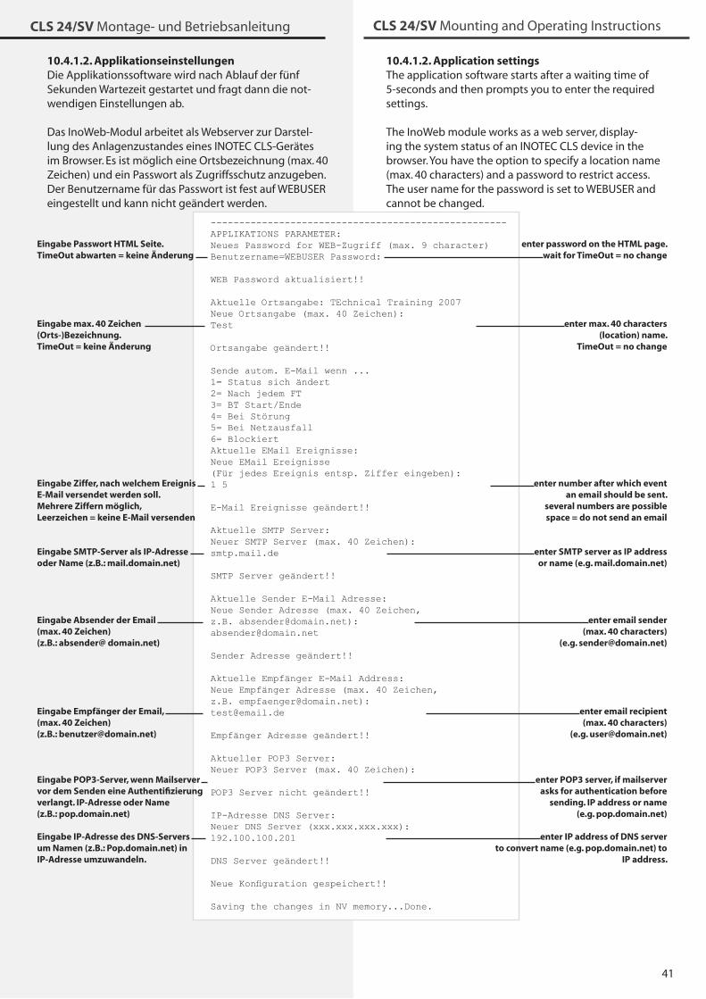
41
CLS 24/SV Montage- und Betriebsanleitung CLS 24/SV Mounting and Operating Instructions
----------------------------------------------------APPLIKATIONS PARAMETER:Neues Password for WEB-Zugriff (max. 9 character)Benutzername=WEBUSER Password:
WEB Password aktualisiert!!
Aktuelle Ortsangabe: TEchnical Training 2007Neue Ortsangabe (max. 40 Zeichen):Test
Ortsangabe geändert!!
Sende autom. E-Mail wenn ...1= Status sich ändert2= Nach jedem FT3= BT Start/Ende4= Bei Störung5= Bei Netzausfall6= BlockiertAktuelle EMail Ereignisse:Neue EMail Ereignisse (Für jedes Ereignis entsp. Ziffer eingeben):1 5
E-Mail Ereignisse geändert!!
Aktuelle SMTP Server:Neuer SMTP Server (max. 40 Zeichen):smtp.mail.de
SMTP Server geändert!!
Aktuelle Sender E-Mail Adresse:Neue Sender Adresse (max. 40 Zeichen, z.B. [email protected]):[email protected]
Sender Adresse geändert!!
Aktuelle Empfänger E-Mail Address:Neue Empfänger Adresse (max. 40 Zeichen, z.B. [email protected]):[email protected]
Empfänger Adresse geändert!!
Aktueller POP3 Server:Neuer POP3 Server (max. 40 Zeichen):
POP3 Server nicht geändert!!
IP-Adresse DNS Server:Neuer DNS Server (xxx.xxx.xxx.xxx):192.100.100.201
DNS Server geändert!!
Neue Konfiguration gespeichert!!
Saving the changes in NV memory...Done.
10.4.1.2. ApplikationseinstellungenDie Applikationssoftware wird nach Ablauf der fünf Sekunden Wartezeit gestartet und fragt dann die not-wendigen Einstellungen ab.
Das InoWeb-Modul arbeitet als Webserver zur Darstel-lung des Anlagenzustandes eines INOTEC CLS-Gerätes im Browser. Es ist möglich eine Ortsbezeichnung (max. 40 Zeichen) und ein Passwort als Zugriffsschutz anzugeben. Der Benutzername für das Passwort ist fest auf WEBUSER eingestellt und kann nicht geändert werden.
Eingabe Passwort HTML Seite. TimeOut abwarten = keine Änderung
Eingabe max. 40 Zeichen (Orts-)Bezeichnung. TimeOut = keine Änderung
Eingabe Ziffer, nach welchem Ereignis E-Mail versendet werden soll. Mehrere Ziffern möglich, Leerzeichen = keine E-Mail versenden
Eingabe SMTP-Server als IP-Adresse oder Name (z.B.: mail.domain.net)
Eingabe Absender der Email (max. 40 Zeichen)(z.B.: absender@ domain.net)
Eingabe Empfänger der Email, (max. 40 Zeichen)(z.B.: [email protected])
Eingabe POP3-Server, wenn Mailserver vor dem Senden eine Authentifizierung verlangt. IP-Adresse oder Name (z.B.: pop.domain.net)
Eingabe IP-Adresse des DNS-Servers um Namen (z.B.: Pop.domain.net) in IP-Adresse umzuwandeln.
10.4.1.2. Application settingsThe application software starts after a waiting time of 5-seconds and then prompts you to enter the required settings.
The InoWeb module works as a web server, display-ing the system status of an INOTEC CLS device in the browser. You have the option to specify a location name (max. 40 characters) and a password to restrict access. The user name for the password is set to WEBUSER and cannot be changed.
enter password on the HTML page.
wait for TimeOut = no change
enter max. 40 characters (location) name.
TimeOut = no change
enter number after which event an email should be sent.
several numbers are possible space = do not send an email
enter SMTP server as IP address or name (e.g. mail.domain.net)
enter email sender (max. 40 characters)
(e.g. [email protected])
enter email recipient (max. 40 characters)
(e.g. [email protected])
enter POP3 server, if mailserver asks for authentication before
sending. IP address or name (e.g. pop.domain.net)
enter IP address of DNS server to convert name (e.g. pop.domain.net) to
IP address.
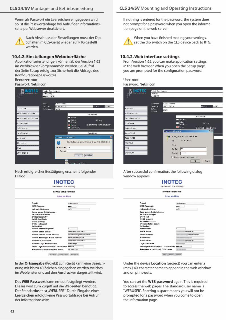
42
CLS 24/SV Montage- und Betriebsanleitung CLS 24/SV Mounting and Operating Instructions
Wenn als Passwort ein Leerzeichen eingegeben wird, so ist die Passwortabfrage bei Aufruf der Informations-seite per Webserver deaktiviert.
Nach Abschluss der Einstellungen muss der Dip - Schalter im CLS-Gerät wieder auf RTG gestellt werden.
10.4.2. Einstellungen WeboberflächeApplikationseinstellungen können ab der Version 1.62 im Webbrowser vorgenommen werden. Bei Aufruf der Seite Setup erfolgt zur Sicherheit die Abfrage des Konfigurationspasswortes.Benutzer: rootPasswort: Netsilicon
Nach erfolgreicher Bestätigung erscheint folgender Dialog:
In der Ortsangabe (Projekt) zum Gerät kann eine Bezeich-nung mit bis zu 40 Zeichen eingegeben werden, welches im Webfenster und auf den Ausdrucken dargestellt wird.
Das WEB Passwort kann erneut festgelegt werden. Dieses wird zum Zugriff auf die Webseiten benötigt. Der Standarduser ist „WEBUSER“. Durch Eingabe eines Leerzeichen erfolgt keine Passwortabfrage bei Aufruf der Informationsseite.
If nothing is entered for the password, the system does not prompt for a password when you open the informa-tion page on the web server.
When you have finished making your settings, set the dip switch on the CLS device back to RTG.
10.4.2. Web interface settingsFrom Version 1.62, you can make application settings in the web browser. When you open the Setup page, you are prompted for the configuration password.
User: rootPassword: Netsilicon
After successful confirmation, the following dialog window appears:
Under the device Location (project) you can enter a (max.) 40-character name to appear in the web window and on print-outs.
You can set the WEB password again. This is required to access the web pages. The standard user name is "WEBUSER". Entering a space means you will not be prompted for a password when you come to open the information page.
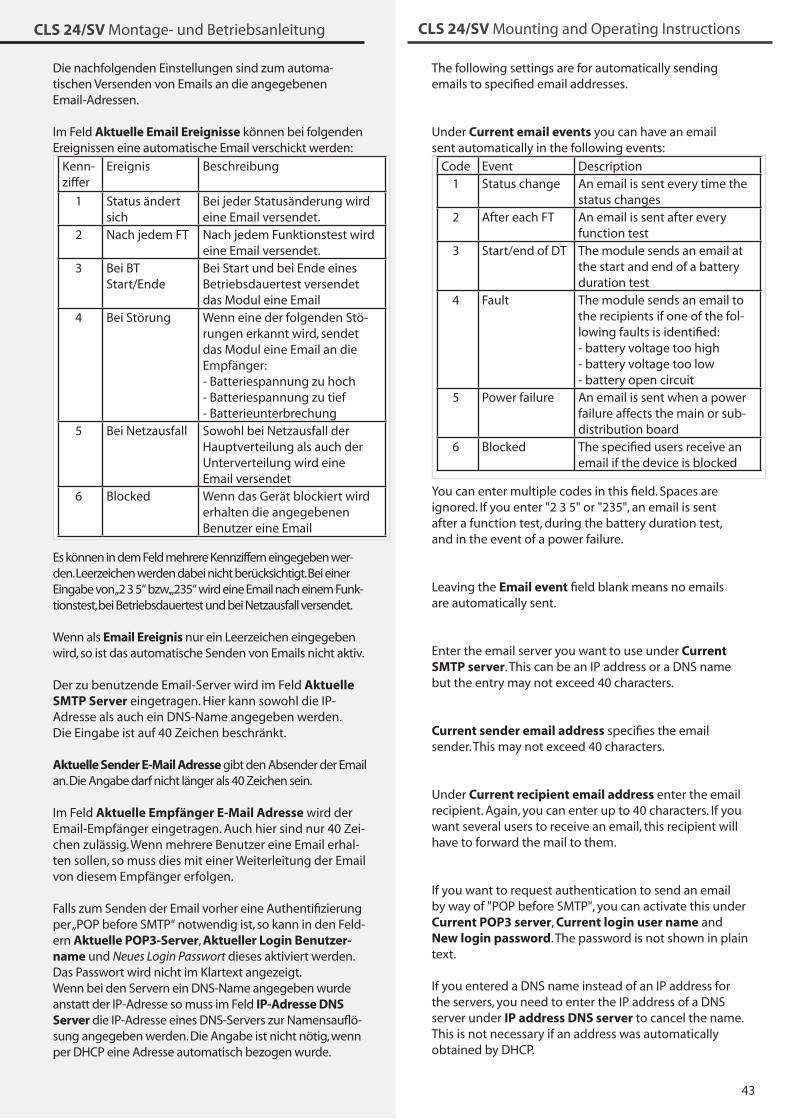
4�
CLS 24/SV Montage- und Betriebsanleitung CLS 24/SV Mounting and Operating Instructions
The following settings are for automatically sending emails to specified email addresses.
Under Current email events you can have an email sent automatically in the following events:
Code Event Description1 Status change An email is sent every time the
status changes2 After each FT An email is sent after every
function test� Start/end of DT The module sends an email at
the start and end of a battery duration test
4 Fault The module sends an email to the recipients if one of the fol-lowing faults is identified:- battery voltage too high- battery voltage too low- battery open circuit
5 Power failure An email is sent when a power failure affects the main or sub-distribution board
6 Blocked The specified users receive an email if the device is blocked
You can enter multiple codes in this field. Spaces are ignored. If you enter "2 � 5" or "2�5", an email is sent after a function test, during the battery duration test, and in the event of a power failure.
Leaving the Email event field blank means no emails are automatically sent.
Enter the email server you want to use under Current SMTP server. This can be an IP address or a DNS name but the entry may not exceed 40 characters.
Current sender email address specifies the email sender. This may not exceed 40 characters.
Under Current recipient email address enter the email recipient. Again, you can enter up to 40 characters. If you want several users to receive an email, this recipient will have to forward the mail to them.
If you want to request authentication to send an email by way of "POP before SMTP", you can activate this under Current POP3 server, Current login user name and New login password. The password is not shown in plain text.
If you entered a DNS name instead of an IP address for the servers, you need to enter the IP address of a DNS server under IP address DNS server to cancel the name. This is not necessary if an address was automatically obtained by DHCP.
Die nachfolgenden Einstellungen sind zum automa-tischen Versenden von Emails an die angegebenen Email-Adressen.
Im Feld Aktuelle Email Ereignisse können bei folgenden Ereignissen eine automatische Email verschickt werden:
Kenn-ziffer
Ereignis Beschreibung
1 Status ändert sich
Bei jeder Statusänderung wird eine Email versendet.
2 Nach jedem FT Nach jedem Funktionstest wird eine Email versendet.
� Bei BT Start/Ende
Bei Start und bei Ende eines Betriebsdauertest versendet das Modul eine Email
4 Bei Störung Wenn eine der folgenden Stö-rungen erkannt wird, sendet das Modul eine Email an die Empfänger:- Batteriespannung zu hoch- Batteriespannung zu tief- Batterieunterbrechung
5 Bei Netzausfall Sowohl bei Netzausfall der Hauptverteilung als auch der Unterverteilung wird eine Email versendet
6 Blocked Wenn das Gerät blockiert wird erhalten die angegebenen Benutzer eine Email
Es können in dem Feld mehrere Kennziffern eingegeben wer-den. Leerzeichen werden dabei nicht berücksichtigt. Bei einer Eingabe von „2 � 5“ bzw. „2�5“ wird eine Email nach einem Funk-tionstest, bei Betriebsdauertest und bei Netzausfall versendet.
Wenn als Email Ereignis nur ein Leerzeichen eingegeben wird, so ist das automatische Senden von Emails nicht aktiv.
Der zu benutzende Email-Server wird im Feld Aktuelle SMTP Server eingetragen. Hier kann sowohl die IP-Adresse als auch ein DNS-Name angegeben werden. Die Eingabe ist auf 40 Zeichen beschränkt.
Aktuelle Sender E-Mail Adresse gibt den Absender der Email an. Die Angabe darf nicht länger als 40 Zeichen sein.
Im Feld Aktuelle Empfänger E-Mail Adresse wird der Email-Empfänger eingetragen. Auch hier sind nur 40 Zei-chen zulässig. Wenn mehrere Benutzer eine Email erhal-ten sollen, so muss dies mit einer Weiterleitung der Email von diesem Empfänger erfolgen.
Falls zum Senden der Email vorher eine Authentifizierung per „POP before SMTP“ notwendig ist, so kann in den Feld-ern Aktuelle POP3-Server, Aktueller Login Benutzer-name und Neues Login Passwort dieses aktiviert werden. Das Passwort wird nicht im Klartext angezeigt.Wenn bei den Servern ein DNS-Name angegeben wurde anstatt der IP-Adresse so muss im Feld IP-Adresse DNS Server die IP-Adresse eines DNS-Servers zur Namensauflö-sung angegeben werden. Die Angabe ist nicht nötig, wenn per DHCP eine Adresse automatisch bezogen wurde.
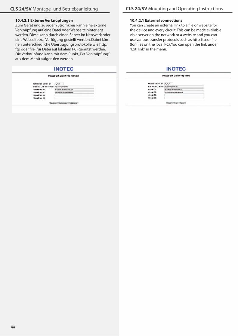
44
CLS 24/SV Montage- und Betriebsanleitung CLS 24/SV Mounting and Operating Instructions
10.4.2.1 Externe VerknüpfungenZum Gerät und zu jedem Stromkreis kann eine externe Verknüpfung auf eine Datei oder Webseite hinterlegt werden. Diese kann durch einen Server im Netzwerk oder eine Webseite zur Verfügung gestellt werden. Dabei kön-nen unterschiedliche Übertragungsprotokolle wie http, ftp oder file (für Datei auf lokalem PC) genutzt werden. Die Verknüpfung kann mit dem Punkt „Ext. Verknüpfung“ aus dem Menü aufgerufen werden.
10.4.2.1 External connectionsYou can create an external link to a file or website for the device and every circuit. This can be made available via a server on the network or a website and you can use various transfer protocols such as http, ftp, or file (for files on the local PC). You can open the link under "Ext. link" in the menu.
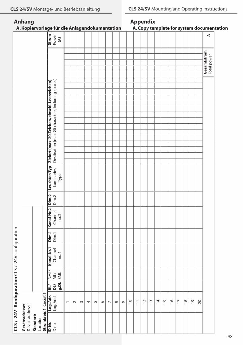
45
CLS 24/SV Montage- und Betriebsanleitung CLS 24/SV Mounting and Operating Instructions
AnhangA. Kopiervorlage für die Anlagendokumentation
CLS
/ 2
4V
- Ko
nfi
gu
rati
on
CLS
/ 2
4V c
on
figu
rati
on
Stro
mkr
eis
1 C
ircu
it 1
Stro
mPo
wer
(A
) A
Zie
lort
(max
. 20
Zei
chen
, ein
sch
l. Le
erze
ich
en)
Des
tin
atio
n (m
ax. 2
0 ch
arac
ters
, in
clu
din
g s
pac
es)
Ges
amts
tro
mTo
tal p
ow
er
Leu
chte
n T
ypLu
min
arie
sTy
pe
Dim
.2D
im.2
Kan
al-N
r.2
Ch
ann
el
no.
2
Dim
.1D
im.1
Kan
al-N
r.1
Ch
ann
el
no.
1
NM
L/M
L/SM
L
BL/
DL/
g.D
L
Ger
ätea
dre
sse:
Dev
ice
add
ress
:
Stan
do
rt:
Loca
tio
n
Log
. Ad
r.Lo
g. A
dd
.
1 2 � 4 5 6 7 8 9 10 11 12 1� 14 15 16 17 18 19 20
ID-N
r.ID
no.
AppendixA. Copy template for system documentation

46
CLS 24/SV Montage- und Betriebsanleitung CLS 24/SV Mounting and Operating InstructionsC
LS /
24
V- K
on
fig
ura
tio
n C
LS /
24V
co
nfig
ura
tio
n
Stro
mkr
eis
2 C
ircu
it 2
Stro
mPo
wer
(A
) A
Zie
lort
(max
. 20
Zei
chen
, ein
sch
l. Le
erze
ich
en)
Des
tin
atio
n (m
ax. 2
0 ch
arac
ters
, in
clu
din
g s
pac
es)
Ges
amts
tro
mTo
tal p
ow
er
Leu
chte
n T
ypLu
min
arie
sTy
pe
Dim
.2D
im.2
Kan
al-N
r.2
Ch
ann
el
no.
2
Dim
.1D
im.1
Kan
al-N
r.1
Ch
ann
el
no.
1
NM
L/M
L/SM
L
BL/
DL/
g.D
L
Ger
ätea
dre
sse:
Dev
ice
add
ress
:
Stan
do
rt:
Loca
tio
n
Log
. Ad
r.Lo
g. A
dd
.
1 2 � 4 5 6 7 8 9 10 11 12 1� 14 15 16 17 18 19 20
ID-N
r.ID
no.

47
CLS 24/SV Montage- und Betriebsanleitung CLS 24/SV Mounting and Operating Instructions
C
LS /
24
V- K
on
fig
ura
tio
n C
LS /
24V
co
nfig
ura
tio
n
Stro
mkr
eis
3 C
ircu
it �
Stro
mPo
wer
(A
) A
Zie
lort
(max
. 20
Zei
chen
, ein
sch
l. Le
erze
ich
en)
Des
tin
atio
n (m
ax. 2
0 ch
arac
ters
, in
clu
din
g s
pac
es)
Ges
amts
tro
mTo
tal p
ow
er
Leu
chte
n T
ypLu
min
arie
sTy
pe
Dim
.2D
im.2
Kan
al-N
r.2
Ch
ann
el
no.
2
Dim
.1D
im.1
Kan
al-N
r.1
Ch
ann
el
no.
1
NM
L/M
L/SM
L
BL/
DL/
g.D
L
Ger
ätea
dre
sse:
Dev
ice
add
ress
:
Stan
do
rt:
Loca
tio
n
Log
. Ad
r.Lo
g. A
dd
.
1 2 � 4 5 6 7 8 9 10 11 12 1� 14 15 16 17 18 19 20
ID-N
r.ID
no.
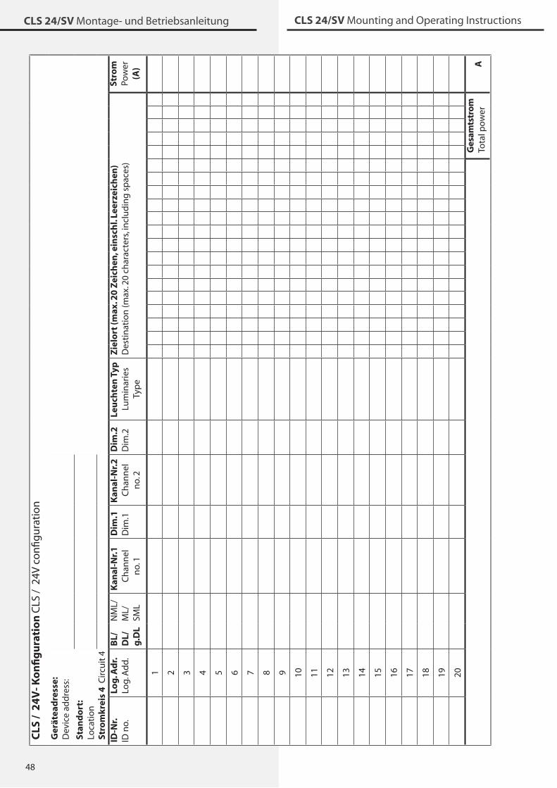
48
CLS 24/SV Montage- und Betriebsanleitung CLS 24/SV Mounting and Operating InstructionsC
LS /
24
V- K
on
fig
ura
tio
n C
LS /
24V
co
nfig
ura
tio
n
Stro
mkr
eis
4 C
ircu
it 4
Stro
mPo
wer
(A
) A
Zie
lort
(max
. 20
Zei
chen
, ein
sch
l. Le
erze
ich
en)
Des
tin
atio
n (m
ax. 2
0 ch
arac
ters
, in
clu
din
g s
pac
es)
Ges
amts
tro
mTo
tal p
ow
er
Leu
chte
n T
ypLu
min
arie
sTy
pe
Dim
.2D
im.2
Kan
al-N
r.2
Ch
ann
el
no.
2
Dim
.1D
im.1
Kan
al-N
r.1
Ch
ann
el
no.
1
NM
L/M
L/SM
L
BL/
DL/
g.D
L
Ger
ätea
dre
sse:
Dev
ice
add
ress
:
Stan
do
rt:
Loca
tio
n
Log
. Ad
r.Lo
g. A
dd
.
1 2 � 4 5 6 7 8 9 10 11 12 1� 14 15 16 17 18 19 20
ID-N
r.ID
no.
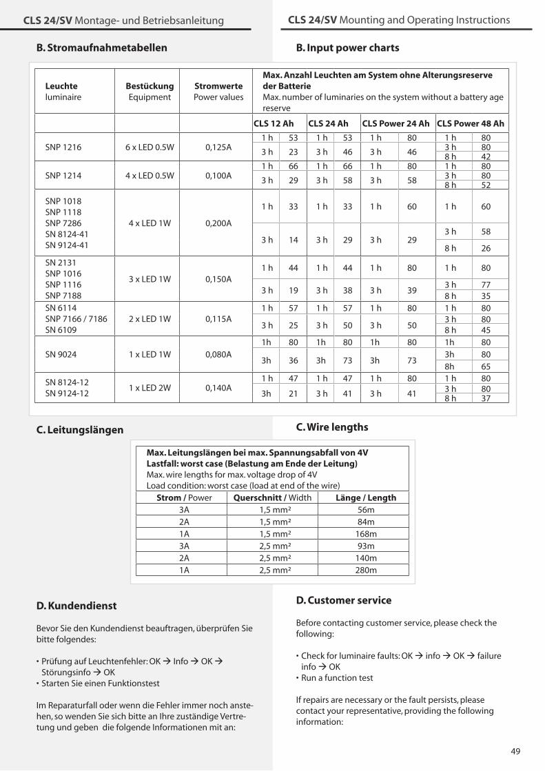
49
CLS 24/SV Montage- und Betriebsanleitung CLS 24/SV Mounting and Operating Instructions
B. Input power charts
C. Wire lengths
D. Customer service
Before contacting customer service, please check the following:
Check for luminaire faults: OK info OK failure info OKRun a function test
If repairs are necessary or the fault persists, please contact your representative, providing the following information:
•
•
B. Stromaufnahmetabellen
C. Leitungslängen
D. Kundendienst
Bevor Sie den Kundendienst beauftragen, überprüfen Sie bitte folgendes:
Prüfung auf Leuchtenfehler: OK Info OK Störungsinfo OKStarten Sie einen Funktionstest
Im Reparaturfall oder wenn die Fehler immer noch anste-hen, so wenden Sie sich bitte an Ihre zuständige Vertre-tung und geben die folgende Informationen mit an:
•
•
Leuchte luminaire
Bestückung Equipment
Stromwerte Power values
Max. Anzahl Leuchten am System ohne Alterungsreserve der Batterie Max. number of luminaries on the system without a battery age reserve
CLS 12 Ah CLS 24 Ah CLS Power 24 Ah CLS Power 48 Ah
SNP 1216 6 x LED 0.5W 0,125A1 h 5� 1 h 5� 1 h 80 1 h 80
� h 2� � h 46 � h 46 � h 808 h 42
SNP 1214 4 x LED 0.5W 0,100A1 h 66 1 h 66 1 h 80 1 h 80
� h 29 � h 58 � h 58 � h 808 h 52
SNP 1018SNP 1118SNP 7286SN 8124-41SN 9124-41
4 x LED 1W 0,200A
1 h �� 1 h �� 1 h 60 1 h 60
� h 14 � h 29 � h 29� h 58
8 h 26
SN 21�1SNP 1016SNP 1116SNP 7188
� x LED 1W 0,150A1 h 44 1 h 44 1 h 80 1 h 80
� h 19 � h �8 � h �9� h 778 h �5
SN 6114SNP 7166 / 7186SN 6109
2 x LED 1W 0,115A1 h 57 1 h 57 1 h 80 1 h 80
� h 25 � h 50 � h 50� h 808 h 45
SN 9024 1 x LED 1W 0,080A1h 80 1h 80 1h 80 1h 80
�h �6 �h 7� �h 7��h 808h 65
SN 8124-12SN 9124-12
1 x LED 2W 0,140A1 h 47 1 h 47 1 h 80 1 h 80
�h 21 � h 41 � h 41 � h 808 h �7
Max. Leitungslängen bei max. Spannungsabfall von 4VLastfall: worst case (Belastung am Ende der Leitung) Max. wire lengths for max. voltage drop of 4VLoad condition: worst case (load at end of the wire)
Strom / Power Querschnitt / Width Länge / Length�A 1,5 mm² 56m2A 1,5 mm² 84m1A 1,5 mm² 168m�A 2,5 mm² 9�m2A 2,5 mm² 140m1A 2,5 mm² 280m
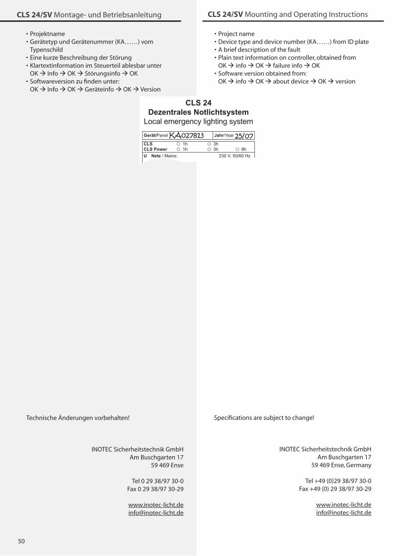
50
CLS 24/SV Montage- und Betriebsanleitung
Project nameDevice type and device number (KA……) from ID plateA brief description of the faultPlain text information on controller, obtained from OK info OK failure info OKSoftware version obtained from: OK info OK about device OK version
••••
•
INOTEC Sicherheitstechnik GmbHAm Buschgarten 17
59 469 Ense, Germany
Tel +49 (0)29 �8/97 �0-0Fax +49 (0) 29 �8/97 �0-29
Specifications are subject to change!
ProjektnameGerätetyp und Gerätenummer (KA……) vom Typenschild Eine kurze Beschreibung der StörungKlartextinformation im Steuerteil ablesbar unter OK Info OK Störungsinfo OKSoftwareversion zu finden unter: OK Info OK Geräteinfo OK Version
••
••
•
KA027813 25/07
INOTEC Sicherheitstechnik GmbHAm Buschgarten 17
59 469 Ense
Tel 0 29 �8/97 �0-0Fax 0 29 �8/97 �0-29
Technische Änderungen vorbehalten!
CLS 24/SV Mounting and Operating Instructions


Sicherheitstechnik GmbH
INOTEC Sicherheitstechnik GmbHAm Buschgarten 17
D - 59 469 Ense
Tel +49 29 �8/97 �0-0 Fax +49 29 �8/97 �0-29
708 120 12/2008


![[sv] Validity date from LAND Vietnam 00269 [SV] SECTION ... · 2 / 33 [sv] List in force Godkännandenum mer Namn Ort [sv] Regions [sv] Activities [sv] Remark [sv] Date of request](https://static.fdocuments.in/doc/165x107/5d66deeb88c99332038b89d9/sv-validity-date-from-land-vietnam-00269-sv-section-2-33-sv-list.jpg)