EMC1428 1°C Multiple Temperature Sensor with HW Thermal ...
53
2014 Microchip Technology Inc. DS20005275A-page 1 Data Sheet PRODUCT FEATURES EMC1428 1°C Multiple Temperature Sensor with HW Thermal Shutdown & Hottest of Thermal Zones General Description The EMC1428 is a high accuracy, low cost, System Management Bus (SMBus) temperature sensor. Advanced features such as Resistance Error Correction (REC), Beta Compensation (to CPU diodes requiring the BJT or transistor model) and automatic diode type detection combine to provide a robust solution for complex environmental monitoring applications. Additionally, the EMC1428 provides a hardware programmable system shutdown feature that is programmed at part power-up via a single TRIP_SET voltage channel that cannot be masked or corrupted through the SMBus. The EMC1428 provides ±1° accuracy for external diode temperatures and ±2°C accuracy for the internal diode temperature. The device monitors up to eight temperature channels (up to seven external and one internal). Applications Notebook Computers Desktop Computers Industrial Embedded Applications Features Hardware Thermal Shutdown — triggers dedicated SYS_SHDN pin — hardware configured range 65°C to 127°C in 1°C steps — cannot be disabled or modified by software Supports diodes requiring the BJT or transistor model Resistance Error Correction (up to 100 Ohms) Up to seven External Temperature Monitors — ±1°C Accuracy (60°C < T DIODE < 100°C) — 0.125°C Resolution — Supports up to 2.2nF filter capacitor — Anti-parallel diodes for extra diode support and compact design Internal Temperature Monitor — ±2°C accuracy 3.3V Supply Voltage Available in a 16-pin 4mm x 4mm QFN RoHS Compliant package Programmable temperature limits for ALER T Block Diagram
Transcript of EMC1428 1°C Multiple Temperature Sensor with HW Thermal ...

2014 Microchip Technology Inc.
PRODUCT FEATURES
EMC1428
1°C Multiple Temperature Sensor with HW Thermal Shutdown & Hottest of Thermal Zones
Data Sheet
General DescriptionThe EMC1428 is a high accuracy, low cost, SystemManagement Bus (SMBus) temperature sensor.Advanced features such as Resistance Error Correction(REC), Beta Compensation (to CPU diodes requiring theBJT or transistor model) and automatic diode typedetection combine to provide a robust solution forcomplex environmental monitoring applications. Additionally, the EMC1428 provides a hardwareprogrammable system shutdown feature that isprogrammed at part power-up via a single TRIP_SETvoltage channel that cannot be masked or corruptedthrough the SMBus.The EMC1428 provides ±1° accuracy for external diodetemperatures and ±2°C accuracy for the internal diodetemperature. The device monitors up to eighttemperature channels (up to seven external and oneinternal). Applications Notebook Computers Desktop Computers Industrial Embedded Applications
Features Hardware Thermal Shutdown
— triggers dedicated SYS_SHDN pin— hardware configured range 65°C to 127°C in 1°C steps— cannot be disabled or modified by software
Supports diodes requiring the BJT or transistor model Resistance Error Correction (up to 100 Ohms) Up to seven External Temperature Monitors
— ±1°C Accuracy (60°C < TDIODE < 100°C)— 0.125°C Resolution— Supports up to 2.2nF filter capacitor— Anti-parallel diodes for extra diode support and
compact design Internal Temperature Monitor
— ±2°C accuracy 3.3V Supply Voltage Available in a 16-pin 4mm x 4mm QFN RoHS
Compliant package Programmable temperature limits for ALERT
Block Diagram
DS20005275A-page 1

O
E
E
EC
1°C Multiple Temperature Sensor with HW Thermal Shutdown & Hottest of Thermal Zones
Data Sheet
ORDER NUMBERS:
Reel Size is 4,000 pieces
This product meets the halogen maximum concentration values per IEC61249-2-21
RDERING NUMBER PACKAGE FEATURES DIODE MODES SUPPORTED
SMBUS ADDRESS
MC1428-1-AP-TR 16-pin QFN (RoHS Compliant)
Up to 7 external diodes. “Hottest Of” temperature comparison. Hardware set Critical / Thermal shutdown, ALERT output
Intel CPU and 3904
1001_100(r/w)
MC1428-6-AP-TR 16-pin QFN (RoHS Compliant)
Up to 7 external diodes. “Hottest Of” temperature comparison. Hardware set Critical / Thermal shutdown, ALERT output
Intel CPU and 3904
1001_101(r/w)
MC1428-7-AP-TR-B7
16-pin QFN (RoHS Compliant)
Up to 7 external diodes. “Hottest Of” temperature comparison. Hardware set Critical / Thermal shutdown, ALERT output
Intel CPU and 3904
Selected by pull-up resistor on SYS_SHDN pin
TO OUR VALUED CUSTOMERSIt is our intention to provide our valued customers with the best documentation possible to ensure successful use of your Microchipproducts. To this end, we will continue to improve our publications to better suit your needs. Our publications will be refined andenhanced as new volumes and updates are introduced. If you have any questions or comments regarding this publication, please contact the Marketing Communications Department viaE-mail at [email protected]. We welcome your feedback.
Most Current Data SheetTo obtain the most up-to-date version of this data sheet, please register at our Worldwide Web site at:
http://www.microchip.com
You can determine the version of a data sheet by examining its literature number found on the bottom outside corner of any page. The last character of the literature number is the version number, (e.g., DS30000000A is version A of document DS30000000).
ErrataAn errata sheet, describing minor operational differences from the data sheet and recommended workarounds, may exist for cur-rent devices. As device/documentation issues become known to us, we will publish an errata sheet. The errata will specify therevision of silicon and revision of document to which it applies.
To determine if an errata sheet exists for a particular device, please check with one of the following:• Microchip’s Worldwide Web site; http://www.microchip.com• Your local Microchip sales office (see last page)When contacting a sales office, please specify which device, revision of silicon and data sheet (include -literature number) you areusing.
Customer Notification SystemRegister on our web site at www.microchip.com to receive the most current information on all of our products.
DS20005275A-page 2 2014 Microchip Technology Inc.
1°C Multiple Temperature Sensor with HW Thermal Shutdown & Hottest of Thermal Zones
Data Sheet
Table of Contents
Chapter 1 Pin Description . . . . . . . . . . . . . . . . . . . . . . . . . . . . . . . . . . . . . . . . . . . . . . . . . . . . . . 7
Chapter 2 Electrical Specifications . . . . . . . . . . . . . . . . . . . . . . . . . . . . . . . . . . . . . . . . . . . . . . . 92.1 Absolute Maximum Ratings. . . . . . . . . . . . . . . . . . . . . . . . . . . . . . . . . . . . . . . . . . . . . . . . . . . . . . . . . . 92.2 Electrical Specifications. . . . . . . . . . . . . . . . . . . . . . . . . . . . . . . . . . . . . . . . . . . . . . . . . . . . . . . . . . . . . 92.3 SMBus Electrical Characteristics. . . . . . . . . . . . . . . . . . . . . . . . . . . . . . . . . . . . . . . . . . . . . . . . . . . . . 11
Chapter 3 System Management Bus Interface Protocol . . . . . . . . . . . . . . . . . . . . . . . . . . . . . 123.1 System Management Bus Interface Protocol . . . . . . . . . . . . . . . . . . . . . . . . . . . . . . . . . . . . . . . . . . . 123.2 Write Byte . . . . . . . . . . . . . . . . . . . . . . . . . . . . . . . . . . . . . . . . . . . . . . . . . . . . . . . . . . . . . . . . . . . . . . 123.3 Read Byte . . . . . . . . . . . . . . . . . . . . . . . . . . . . . . . . . . . . . . . . . . . . . . . . . . . . . . . . . . . . . . . . . . . . . . 133.4 Send Byte . . . . . . . . . . . . . . . . . . . . . . . . . . . . . . . . . . . . . . . . . . . . . . . . . . . . . . . . . . . . . . . . . . . . . . 133.5 Receive Byte . . . . . . . . . . . . . . . . . . . . . . . . . . . . . . . . . . . . . . . . . . . . . . . . . . . . . . . . . . . . . . . . . . . . 133.6 Alert Response Address . . . . . . . . . . . . . . . . . . . . . . . . . . . . . . . . . . . . . . . . . . . . . . . . . . . . . . . . . . . 133.7 SMBus Address. . . . . . . . . . . . . . . . . . . . . . . . . . . . . . . . . . . . . . . . . . . . . . . . . . . . . . . . . . . . . . . . . . 143.8 SMBus Timeout . . . . . . . . . . . . . . . . . . . . . . . . . . . . . . . . . . . . . . . . . . . . . . . . . . . . . . . . . . . . . . . . . . 14
Chapter 4 Product Description . . . . . . . . . . . . . . . . . . . . . . . . . . . . . . . . . . . . . . . . . . . . . . . . . 154.1 ALERT Output . . . . . . . . . . . . . . . . . . . . . . . . . . . . . . . . . . . . . . . . . . . . . . . . . . . . . . . . . . . . . . . . . . . 16
4.1.1 ALERT Pin Interrupt Mode. . . . . . . . . . . . . . . . . . . . . . . . . . . . . . . . . . . . . . . . . . . . . . . . . . . 164.1.2 ALERT Pin Comparator Mode . . . . . . . . . . . . . . . . . . . . . . . . . . . . . . . . . . . . . . . . . . . . . . . . 16
4.2 SYS_SHDN Output . . . . . . . . . . . . . . . . . . . . . . . . . . . . . . . . . . . . . . . . . . . . . . . . . . . . . . . . . . . . . . . 164.3 TRIP_SET Pin . . . . . . . . . . . . . . . . . . . . . . . . . . . . . . . . . . . . . . . . . . . . . . . . . . . . . . . . . . . . . . . . . . . 174.4 Consecutive Alerts. . . . . . . . . . . . . . . . . . . . . . . . . . . . . . . . . . . . . . . . . . . . . . . . . . . . . . . . . . . . . . . . 194.5 Temperature Monitoring . . . . . . . . . . . . . . . . . . . . . . . . . . . . . . . . . . . . . . . . . . . . . . . . . . . . . . . . . . . 19
4.5.1 Resistance Error Correction . . . . . . . . . . . . . . . . . . . . . . . . . . . . . . . . . . . . . . . . . . . . . . . . . 204.5.2 Beta Compensation . . . . . . . . . . . . . . . . . . . . . . . . . . . . . . . . . . . . . . . . . . . . . . . . . . . . . . . . 204.5.3 Digital Averaging . . . . . . . . . . . . . . . . . . . . . . . . . . . . . . . . . . . . . . . . . . . . . . . . . . . . . . . . . . 204.5.4 “Hottest Of” Comparison . . . . . . . . . . . . . . . . . . . . . . . . . . . . . . . . . . . . . . . . . . . . . . . . . . . . 204.5.5 Conversion Rates . . . . . . . . . . . . . . . . . . . . . . . . . . . . . . . . . . . . . . . . . . . . . . . . . . . . . . . . . 214.5.6 Dynamic Averaging . . . . . . . . . . . . . . . . . . . . . . . . . . . . . . . . . . . . . . . . . . . . . . . . . . . . . . . . 21
4.6 Diode Connections . . . . . . . . . . . . . . . . . . . . . . . . . . . . . . . . . . . . . . . . . . . . . . . . . . . . . . . . . . . . . . . 214.6.1 Diode Faults. . . . . . . . . . . . . . . . . . . . . . . . . . . . . . . . . . . . . . . . . . . . . . . . . . . . . . . . . . . . . . 22
Chapter 5 Register Description . . . . . . . . . . . . . . . . . . . . . . . . . . . . . . . . . . . . . . . . . . . . . . . . . 235.1 Data Read Interlock. . . . . . . . . . . . . . . . . . . . . . . . . . . . . . . . . . . . . . . . . . . . . . . . . . . . . . . . . . . . . . . 285.2 Temperature Data Registers . . . . . . . . . . . . . . . . . . . . . . . . . . . . . . . . . . . . . . . . . . . . . . . . . . . . . . . . 285.3 Status Register . . . . . . . . . . . . . . . . . . . . . . . . . . . . . . . . . . . . . . . . . . . . . . . . . . . . . . . . . . . . . . . . . . 305.4 Configuration Register. . . . . . . . . . . . . . . . . . . . . . . . . . . . . . . . . . . . . . . . . . . . . . . . . . . . . . . . . . . . . 305.5 Conversion Rate Register . . . . . . . . . . . . . . . . . . . . . . . . . . . . . . . . . . . . . . . . . . . . . . . . . . . . . . . . . . 315.6 Limit Registers. . . . . . . . . . . . . . . . . . . . . . . . . . . . . . . . . . . . . . . . . . . . . . . . . . . . . . . . . . . . . . . . . . . 325.7 Therm Hysteresis Register . . . . . . . . . . . . . . . . . . . . . . . . . . . . . . . . . . . . . . . . . . . . . . . . . . . . . . . . . 355.8 Therm Limit Registers . . . . . . . . . . . . . . . . . . . . . . . . . . . . . . . . . . . . . . . . . . . . . . . . . . . . . . . . . . . . . 355.9 External Diode Fault Register . . . . . . . . . . . . . . . . . . . . . . . . . . . . . . . . . . . . . . . . . . . . . . . . . . . . . . . 365.10 TRIP_SET Reading Register. . . . . . . . . . . . . . . . . . . . . . . . . . . . . . . . . . . . . . . . . . . . . . . . . . . . . . . 365.11 Software Thermal Shutdown Configuration Register . . . . . . . . . . . . . . . . . . . . . . . . . . . . . . . . . . . . 365.12 Hardware Critical / Thermal Shutdown Limit Register. . . . . . . . . . . . . . . . . . . . . . . . . . . . . . . . . . . . 375.13 Channel Interrupt Mask Register. . . . . . . . . . . . . . . . . . . . . . . . . . . . . . . . . . . . . . . . . . . . . . . . . . . . 37
2014 Microchip Technology Inc. DS20005275A-page 3
1°C Multiple Temperature Sensor with HW Thermal Shutdown & Hottest of Thermal Zones
Data Sheet
5.14 Consecutive ALERT Register . . . . . . . . . . . . . . . . . . . . . . . . . . . . . . . . . . . . . . . . . . . . . . . . . . . . . . 385.15 Beta Configuration Register . . . . . . . . . . . . . . . . . . . . . . . . . . . . . . . . . . . . . . . . . . . . . . . . . . . . . . . 405.16 Hottest Temperature Registers . . . . . . . . . . . . . . . . . . . . . . . . . . . . . . . . . . . . . . . . . . . . . . . . . . . . . 415.17 Hottest Temperature Status Register . . . . . . . . . . . . . . . . . . . . . . . . . . . . . . . . . . . . . . . . . . . . . . . . 415.18 High Limit Status Register . . . . . . . . . . . . . . . . . . . . . . . . . . . . . . . . . . . . . . . . . . . . . . . . . . . . . . . . . 425.19 Low Limit Status Register . . . . . . . . . . . . . . . . . . . . . . . . . . . . . . . . . . . . . . . . . . . . . . . . . . . . . . . . . 435.20 THERM Limit Status Register . . . . . . . . . . . . . . . . . . . . . . . . . . . . . . . . . . . . . . . . . . . . . . . . . . . . . . 435.21 REC Configuration Register . . . . . . . . . . . . . . . . . . . . . . . . . . . . . . . . . . . . . . . . . . . . . . . . . . . . . . . 445.22 Hottest Configuration Register . . . . . . . . . . . . . . . . . . . . . . . . . . . . . . . . . . . . . . . . . . . . . . . . . . . . . 445.23 Channel Configuration Register . . . . . . . . . . . . . . . . . . . . . . . . . . . . . . . . . . . . . . . . . . . . . . . . . . . . 455.24 Filter Control Register . . . . . . . . . . . . . . . . . . . . . . . . . . . . . . . . . . . . . . . . . . . . . . . . . . . . . . . . . . . . 465.25 Product ID Register . . . . . . . . . . . . . . . . . . . . . . . . . . . . . . . . . . . . . . . . . . . . . . . . . . . . . . . . . . . . . . 465.26 Manufacturer ID Register (FEh) . . . . . . . . . . . . . . . . . . . . . . . . . . . . . . . . . . . . . . . . . . . . . . . . . . . . 465.27 Revision Register (FFh). . . . . . . . . . . . . . . . . . . . . . . . . . . . . . . . . . . . . . . . . . . . . . . . . . . . . . . . . . . 47
Chapter 6 Package Information . . . . . . . . . . . . . . . . . . . . . . . . . . . . . . . . . . . . . . . . . . . . . . . . 486.1 EMC1428 Package Drawing . . . . . . . . . . . . . . . . . . . . . . . . . . . . . . . . . . . . . . . . . . . . . . . . . . . . . . . . 486.2 Package Markings . . . . . . . . . . . . . . . . . . . . . . . . . . . . . . . . . . . . . . . . . . . . . . . . . . . . . . . . . . . . . . . . 50
6.2.1 EMC1428-X-AP (16-Pin QFN). . . . . . . . . . . . . . . . . . . . . . . . . . . . . . . . . . . . . . . . . . . . . . . . 50
Chapter 7 Data Sheet Revision History . . . . . . . . . . . . . . . . . . . . . . . . . . . . . . . . . . . . . . . . . . 51
DS20005275A-page 4 2014 Microchip Technology Inc.

1°C Multiple Temperature Sensor with HW Thermal Shutdown & Hottest of Thermal Zones
Data Sheet
2014 Microchip Technology Inc. DS20005275A-page 5
List of FiguresFigure 1.1 EMC1428 Pin Diagram . . . . . . . . . . . . . . . . . . . . . . . . . . . . . . . . . . . . . . . . . . . . . . . . . . . . . . 7Figure 3.1 SMBus Timing Diagram . . . . . . . . . . . . . . . . . . . . . . . . . . . . . . . . . . . . . . . . . . . . . . . . . . . . . 12Figure 4.1 System Diagram for EMC1428 . . . . . . . . . . . . . . . . . . . . . . . . . . . . . . . . . . . . . . . . . . . . . . . 15Figure 4.2 Block Diagram of Hardware Thermal Shutdown . . . . . . . . . . . . . . . . . . . . . . . . . . . . . . . . . . 17Figure 4.3 Vset Circuit. . . . . . . . . . . . . . . . . . . . . . . . . . . . . . . . . . . . . . . . . . . . . . . . . . . . . . . . . . . . . . . 18Figure 4.4 Diode Connections. . . . . . . . . . . . . . . . . . . . . . . . . . . . . . . . . . . . . . . . . . . . . . . . . . . . . . . . . 22Figure 6.1 16-Pin QFN 4mm x 4mm Package Dimensions. . . . . . . . . . . . . . . . . . . . . . . . . . . . . . . . . . . 48Figure 6.2 16-Pin QFN 4mm x 4mm Package Drawing . . . . . . . . . . . . . . . . . . . . . . . . . . . . . . . . . . . . . 49Figure 6.3 16-Pin QFN 4mm x 4mm PCB Footprint . . . . . . . . . . . . . . . . . . . . . . . . . . . . . . . . . . . . . . . . 50

1°C Multiple Temperature Sensor with HW Thermal Shutdown & Hottest of Thermal Zones
Data Sheet
DS20005275A-page 6 2014 Microchip Technology Inc.
List of TablesTable 1.1 EMC1428 Pin Description . . . . . . . . . . . . . . . . . . . . . . . . . . . . . . . . . . . . . . . . . . . . . . . . . . . . . 7Table 1.2 Pin Type. . . . . . . . . . . . . . . . . . . . . . . . . . . . . . . . . . . . . . . . . . . . . . . . . . . . . . . . . . . . . . . . . . . 8Table 2.1 Absolute Maximum Ratings . . . . . . . . . . . . . . . . . . . . . . . . . . . . . . . . . . . . . . . . . . . . . . . . . . . . 9Table 2.2 Electrical Specifications . . . . . . . . . . . . . . . . . . . . . . . . . . . . . . . . . . . . . . . . . . . . . . . . . . . . . . . 9Table 2.3 SMBus Electrical Specifications . . . . . . . . . . . . . . . . . . . . . . . . . . . . . . . . . . . . . . . . . . . . . . . 11Table 3.1 Protocol Format . . . . . . . . . . . . . . . . . . . . . . . . . . . . . . . . . . . . . . . . . . . . . . . . . . . . . . . . . . . . 12Table 3.2 Write Byte Protocol . . . . . . . . . . . . . . . . . . . . . . . . . . . . . . . . . . . . . . . . . . . . . . . . . . . . . . . . . 12Table 3.3 Read Byte Protocol . . . . . . . . . . . . . . . . . . . . . . . . . . . . . . . . . . . . . . . . . . . . . . . . . . . . . . . . . 13Table 3.4 Send Byte Protocol . . . . . . . . . . . . . . . . . . . . . . . . . . . . . . . . . . . . . . . . . . . . . . . . . . . . . . . . . 13Table 3.5 Receive Byte Protocol . . . . . . . . . . . . . . . . . . . . . . . . . . . . . . . . . . . . . . . . . . . . . . . . . . . . . . . 13Table 3.6 Alert Response Address Protocol . . . . . . . . . . . . . . . . . . . . . . . . . . . . . . . . . . . . . . . . . . . . . . 14Table 3.7 Address Select Decode on SYS_SHDN Pin . . . . . . . . . . . . . . . . . . . . . . . . . . . . . . . . . . . . . . 14Table 4.1 VTRIP Resistor Settings . . . . . . . . . . . . . . . . . . . . . . . . . . . . . . . . . . . . . . . . . . . . . . . . . . . . . . 18Table 4.2 Supply Current vs. Conversion Rate for EMC1428 . . . . . . . . . . . . . . . . . . . . . . . . . . . . . . . . . 21Table 5.1 Register Set in Hexadecimal Order . . . . . . . . . . . . . . . . . . . . . . . . . . . . . . . . . . . . . . . . . . . . . 23Table 5.2 Temperature Data Registers . . . . . . . . . . . . . . . . . . . . . . . . . . . . . . . . . . . . . . . . . . . . . . . . . . 28Table 5.3 Temperature Data Format . . . . . . . . . . . . . . . . . . . . . . . . . . . . . . . . . . . . . . . . . . . . . . . . . . . . 29Table 5.4 Status Register . . . . . . . . . . . . . . . . . . . . . . . . . . . . . . . . . . . . . . . . . . . . . . . . . . . . . . . . . . . . 30Table 5.5 Configuration Register . . . . . . . . . . . . . . . . . . . . . . . . . . . . . . . . . . . . . . . . . . . . . . . . . . . . . . . 30Table 5.6 Conversion Rate Register . . . . . . . . . . . . . . . . . . . . . . . . . . . . . . . . . . . . . . . . . . . . . . . . . . . . 31Table 5.7 Conversion Rate . . . . . . . . . . . . . . . . . . . . . . . . . . . . . . . . . . . . . . . . . . . . . . . . . . . . . . . . . . . 31Table 5.8 Maximum Conversion Rate Per Temperature Channels . . . . . . . . . . . . . . . . . . . . . . . . . . . . . 32Table 5.9 Temperature Limit Registers . . . . . . . . . . . . . . . . . . . . . . . . . . . . . . . . . . . . . . . . . . . . . . . . . . 32Table 5.10 Therm Hysteresis Register . . . . . . . . . . . . . . . . . . . . . . . . . . . . . . . . . . . . . . . . . . . . . . . . . . . 35Table 5.11 Therm Limit Registers . . . . . . . . . . . . . . . . . . . . . . . . . . . . . . . . . . . . . . . . . . . . . . . . . . . . . . . 35Table 5.12 External Diode Fault Register . . . . . . . . . . . . . . . . . . . . . . . . . . . . . . . . . . . . . . . . . . . . . . . . . 36Table 5.13 TRIP_SET Reading Register. . . . . . . . . . . . . . . . . . . . . . . . . . . . . . . . . . . . . . . . . . . . . . . . . . 36Table 5.14 Software Thermal Shutdown Configuration Register. . . . . . . . . . . . . . . . . . . . . . . . . . . . . . . . 36Table 5.15 Hardware Thermal Shutdown Limit Register . . . . . . . . . . . . . . . . . . . . . . . . . . . . . . . . . . . . . . 37Table 5.16 Channel Interrupt Mask Register . . . . . . . . . . . . . . . . . . . . . . . . . . . . . . . . . . . . . . . . . . . . . . . 37Table 5.17 Consecutive ALERT Register . . . . . . . . . . . . . . . . . . . . . . . . . . . . . . . . . . . . . . . . . . . . . . . . . 38Table 5.18 Consecutive Alert Settings. . . . . . . . . . . . . . . . . . . . . . . . . . . . . . . . . . . . . . . . . . . . . . . . . . . . 39Table 5.19 Beta Configuration Register. . . . . . . . . . . . . . . . . . . . . . . . . . . . . . . . . . . . . . . . . . . . . . . . . . . 40Table 5.20 Beta Compensation Look Up Table. . . . . . . . . . . . . . . . . . . . . . . . . . . . . . . . . . . . . . . . . . . . . 40Table 5.21 Hottest Temperature Registers . . . . . . . . . . . . . . . . . . . . . . . . . . . . . . . . . . . . . . . . . . . . . . . . 41Table 5.22 Hottest Temperature Register . . . . . . . . . . . . . . . . . . . . . . . . . . . . . . . . . . . . . . . . . . . . . . . . . 41Table 5.23 High Limit Status Register . . . . . . . . . . . . . . . . . . . . . . . . . . . . . . . . . . . . . . . . . . . . . . . . . . . . 42Table 5.24 Low Limit Status Register . . . . . . . . . . . . . . . . . . . . . . . . . . . . . . . . . . . . . . . . . . . . . . . . . . . . 43Table 5.25 THERM Limit Status Register . . . . . . . . . . . . . . . . . . . . . . . . . . . . . . . . . . . . . . . . . . . . . . . . . 43Table 5.26 REC Configuration Register . . . . . . . . . . . . . . . . . . . . . . . . . . . . . . . . . . . . . . . . . . . . . . . . . . 44Table 5.27 Hottest Configuration Register. . . . . . . . . . . . . . . . . . . . . . . . . . . . . . . . . . . . . . . . . . . . . . . . . 44Table 5.28 Channel Configuration Register. . . . . . . . . . . . . . . . . . . . . . . . . . . . . . . . . . . . . . . . . . . . . . . . 45Table 5.29 Filter Control Register . . . . . . . . . . . . . . . . . . . . . . . . . . . . . . . . . . . . . . . . . . . . . . . . . . . . . . . 46Table 5.30 Product ID Register . . . . . . . . . . . . . . . . . . . . . . . . . . . . . . . . . . . . . . . . . . . . . . . . . . . . . . . . . 46Table 5.31 Manufacturer ID Register. . . . . . . . . . . . . . . . . . . . . . . . . . . . . . . . . . . . . . . . . . . . . . . . . . . . . 46Table 5.32 Revision Register. . . . . . . . . . . . . . . . . . . . . . . . . . . . . . . . . . . . . . . . . . . . . . . . . . . . . . . . . . . 47Table 7.1 Revision History. . . . . . . . . . . . . . . . . . . . . . . . . . . . . . . . . . . . . . . . . . . . . . . . . . . . . . . . . . . . 51

1°C Multiple Temperature Sensor with HW Thermal Shutdown & Hottest of Thermal Zones
Data Sheet
Chapter 1 Pin Description
Figure 1.1 EMC1428 Pin Diagram
Table 1.1 EMC1428 Pin Description
PIN NUMBER NAME FUNCTION TYPE
1 DP1 DP1 - External Diode 1 positive (anode) connection.
AIO
2 DN1 External Diode 1 negative (cathode) connection.
AIO
3 DP2 / DN3 External Diode 2 positive (anode) connection and External Diode 3
negative (cathode) connection
AIO
4 DN2 / DP3 External diode 2 negative (cathode) connection and External Diode 3
positive (anode) connection
AIO
5 TRIP_SET Voltage input to set Critical / Thermal Shutdown temperature
AIO
2014 Microchip Technology Inc. DS20005275A-page 7

1°C Multiple Temperature Sensor with HW Thermal Shutdown & Hottest of Thermal Zones
Data Sheet
The pin types are described below. All pins labelled (5V) are 5V tolerant.
APPLICATION NOTE: For the 5V tolerant pins that have a pull-up resistor, the voltage difference between VDD andthe pull-up voltage must never exceed 3.6V.
6 SYS_SHDN Active low System Shutdown output signal - requires pull-up resistor
EMC1428-7 - The pull-up resistor is used to determine SMBus address
OD (5V)
7 ALERT Active low interrupt - requires pull-up resistor
OD (5V)
8 GND Ground Connection Power
9 DN4 / DP5 External diode 4 negative (cathode) connection and External Diode 5
positive (anode) connection
AIO
10 DP4 / DN5 External Diode 4 positive (anode) connection and External Diode 5
negative (cathode) connection
AIO
11 SMDATA SMBus Data input/output - requires pull-up resistor
DIOD (5V)
12 SMCLK SMBus Clock input - requires pull-up resistor
DI (5V)
13 N/C Not used - connect to Ground - see EMC1428 Anomaly Sheet
n/a
14 DN6 / DP7 External diode 6 negative (cathode) connection and External Diode 7
positive (anode) connection
AIO
15 DP6 / DN7 External Diode 6 positive (anode) connection and External Diode 7
negative (cathode) connection
AIO
16 VDD Power supply Power
Table 1.2 Pin Type
PIN TYPE FUNCTION
Power Used to supply either VDD or GND to the device
DI 5V tolerant digital input
OD 5V tolerant Open drain digital output. Requires a pull-up resistor
DIOD 5V tolerant bi-directional digital input / open-drain output. Requires a pull-up resistor.
AIO Analog input / output used for external diodes or analog inputs
Table 1.1 EMC1428 Pin Description (continued)
PIN NUMBER NAME FUNCTION TYPE
DS20005275A-page 8 2014 Microchip Technology Inc.

1°C Multiple Temperature Sensor with HW Thermal Shutdown & Hottest of Thermal Zones
Data Sheet
Chapter 2 Electrical Specifications
2.1 Absolute Maximum Ratings
Note: Stresses at or above those listed could cause permanent damage to the device. This is a stressrating only and functional operation of the device at any other condition above those indicatedin the operation sections of this specification is not implied. When powering this device fromlaboratory or system power supplies, it is important that the Absolute Maximum Ratings not beexceeded or device failure can result. Some power supplies exhibit voltage spikes on theiroutputs when the AC power is switched on or off. In addition, voltage transients on the ACpower line may appear on the DC output. If this possibility exists, it is suggested that a clampcircuit be used.
Note 2.1 For the 5V tolerant pins that have a pull-up resistor, the pull-up voltage must not exceed3.6V when the device is unpowered.
2.2 Electrical Specifications
Table 2.1 Absolute Maximum Ratings
DESCRIPTION RATING UNIT
Supply Voltage (VDD) -0.3 to 4.0 V
Voltage on 5V tolerant pins (V5VT_pin) -0.3 to 5.5 V
Voltage on 5V tolerant pins (|V5VT_pin - VDD|) (see Note 2.1) -0.3 to 3.6 V
Voltage on any other pin to Ground -0.3 to VDD +0.3 V
Operating Temperature Range -40 to +125 °C
Storage Temperature Range -55 to +150 °C
Lead Temperature Range Refer to JEDEC Spec. J-STD-020
Package Thermal Characteristics for QFN-16
Thermal Resistance (j-a) 50 °C/W
ESD Rating, All pins HBM 2000 V
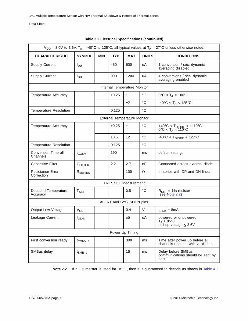
Table 2.2 Electrical Specifications
VDD = 3.0V to 3.6V, TA = -40°C to 125°C, all typical values at TA = 27°C unless otherwise noted.
CHARACTERISTIC SYMBOL MIN TYP MAX UNITS CONDITIONS
DC Power
Supply Voltage VDD 3.0 3.3 3.6 V
2014 Microchip Technology Inc. DS20005275A-page 9
1°C Multiple Temperature Sensor with HW Thermal Shutdown & Hottest of Thermal Zones
Data Sheet
Note 2.2 If a 1% resistor is used for RSET, then it is guaranteed to decode as shown in Table 4.1.
Supply Current IDD 450 600 uA 1 conversion / sec, dynamic averaging disabled
Supply Current IDD 900 1200 uA 4 conversions / sec, dynamic averaging enabled
Internal Temperature Monitor
Temperature Accuracy ±0.25 ±1 °C 0°C < TA < 100°C
±2 °C -40°C < TA < 125°C
Temperature Resolution 0.125 °C
External Temperature Monitor
Temperature Accuracy ±0.25 ±1 °C +40°C < TDIODE < +110°C 0°C < TA < 110°C
±0.5 ±2 °C -40°C < TDIODE < 127°C
Temperature Resolution 0.125 °C
Conversion Time all Channels
tCONV 190 ms default settings
Capacitive Filter CFILTER 2.2 2.7 nF Connected across external diode
Resistance Error Correction
RSERIES 100 In series with DP and DN lines
TRIP_SET Measurement
Decoded Temperature Accuracy
TSET 0.5 °C RSET = 1% resistor (see Note 2.2)
ALERT and SYS_SHDN pins
Output Low Voltage VOL 0.4 V ISINK = 8mA
Leakage Current ILEAK ±5 uA powered or unpoweredTA < 85°Cpull-up voltage < 3.6V
Power Up Timing
First conversion ready tCONV_f 300 ms Time after power up before all channels updated with valid data
SMBus delay tSMB_d 15 ms Delay before SMBus communications should be sent by host
Table 2.2 Electrical Specifications (continued)
VDD = 3.0V to 3.6V, TA = -40°C to 125°C, all typical values at TA = 27°C unless otherwise noted.
CHARACTERISTIC SYMBOL MIN TYP MAX UNITS CONDITIONS
DS20005275A-page 10 2014 Microchip Technology Inc.
1°C Multiple Temperature Sensor with HW Thermal Shutdown & Hottest of Thermal Zones
Data Sheet
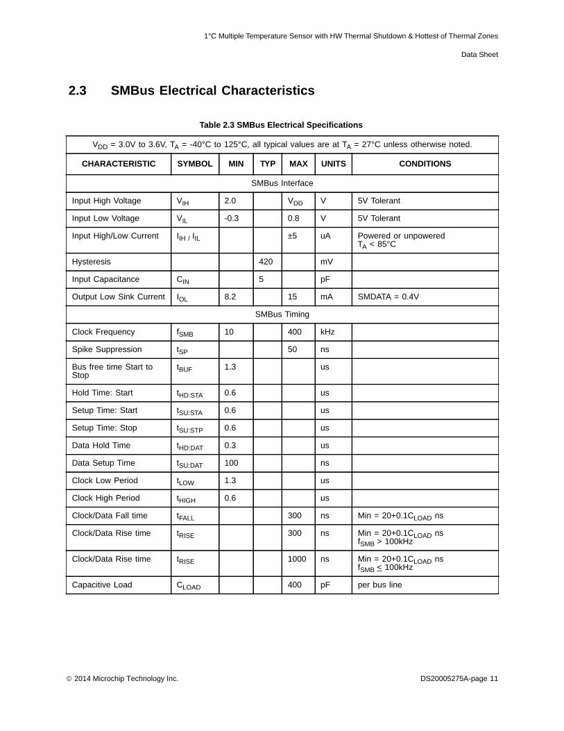
2.3 SMBus Electrical Characteristics
Table 2.3 SMBus Electrical Specifications
VDD = 3.0V to 3.6V, TA = -40°C to 125°C, all typical values are at TA = 27°C unless otherwise noted.
CHARACTERISTIC SYMBOL MIN TYP MAX UNITS CONDITIONS
SMBus Interface
Input High Voltage VIH 2.0 VDD V 5V Tolerant
Input Low Voltage VIL -0.3 0.8 V 5V Tolerant
Input High/Low Current IIH / IIL ±5 uA Powered or unpoweredTA < 85°C
Hysteresis 420 mV
Input Capacitance CIN 5 pF
Output Low Sink Current IOL 8.2 15 mA SMDATA = 0.4V
SMBus Timing
Clock Frequency fSMB 10 400 kHz
Spike Suppression tSP 50 ns
Bus free time Start to Stop
tBUF 1.3 us
Hold Time: Start tHD:STA 0.6 us
Setup Time: Start tSU:STA 0.6 us
Setup Time: Stop tSU:STP 0.6 us
Data Hold Time tHD:DAT 0.3 us
Data Setup Time tSU:DAT 100 ns
Clock Low Period tLOW 1.3 us
Clock High Period tHIGH 0.6 us
Clock/Data Fall time tFALL 300 ns Min = 20+0.1CLOAD ns
Clock/Data Rise time tRISE 300 ns Min = 20+0.1CLOAD ns fSMB > 100kHz
Clock/Data Rise time tRISE 1000 ns Min = 20+0.1CLOAD ns fSMB < 100kHz
Capacitive Load CLOAD 400 pF per bus line
2014 Microchip Technology Inc. DS20005275A-page 11

1°C Multiple Temperature Sensor with HW Thermal Shutdown & Hottest of Thermal Zones
Data Sheet
Chapter 3 System Management Bus Interface Protocol
3.1 System Management Bus Interface ProtocolThe EMC1428 communicate with a host controller, such as a Microchip SIO, through the SMBus. TheSMBus is a two-wire serial communication protocol between a computer host and its peripheraldevices. A detailed timing diagram is shown in Figure 3.1.
The EMC1428 are SMBus 2.0 compatible and support Send Byte, Read Byte, Write Byte, ReceiveByte, and the Alert Response Address as valid protocols as shown below.
All of the below protocols use the convention in Table 3.1.
Attempting to communicate with the EMC1428 SMBus interface with an invalid slave address or invalidprotocol will result in no response from the device and will not affect its register contents. Stretchingof the SMCLK signal is supported, provided other devices on the SMBus control the timing.
3.2 Write ByteThe Write Byte is used to write one byte of data to the registers as shown below Table 3.2:
Figure 3.1 SMBus Timing Diagram
Table 3.1 Protocol Format
DATA SENT TO DEVICE
DATA SENT TO THE HOST
Table 3.2 Write Byte Protocol
STARTSLAVE
ADDRESS WR ACKREGISTER ADDRESS ACK
REGISTER DATA ACK STOP
1 -> 0 1001_100 0 0 XXh 0 XXh 0 0 -> 1
DS20005275A-page 12 2014 Microchip Technology Inc.

1°C Multiple Temperature Sensor with HW Thermal Shutdown & Hottest of Thermal Zones
Data Sheet
3.3 Read ByteThe Read Byte protocol is used to read one byte of data from the registers as shown in Table 3.3.
3.4 Send ByteThe Send Byte protocol is used to set the internal address register pointer to the correct addresslocation. No data is transferred during the Send Byte protocol as shown in Table 3.4.
3.5 Receive ByteThe Receive Byte protocol is used to read data from a register when the internal register addresspointer is known to be at the right location (e.g. set via Send Byte). This is used for consecutive readsof the same register as shown in Table 3.5.
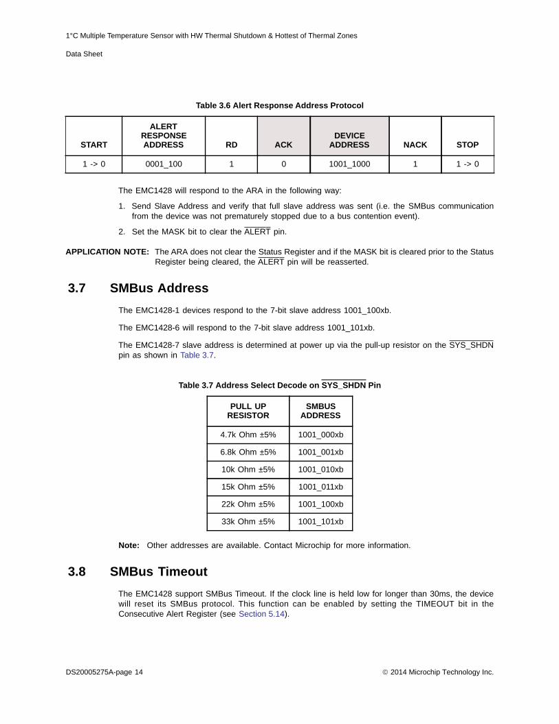
3.6 Alert Response AddressThe ALERT output can be used as a processor interrupt or as an SMBus Alert.
When it detects that the ALERT pin is asserted, the host will send the Alert Response Address (ARA)to the general address of 000_1100b. All devices with active interrupts will respond with their clientaddress as shown in Table 3.6.
Table 3.3 Read Byte Protocol
START SLAVE ADDRESS
WR ACK REGISTER ADDRESS
ACK START SLAVE ADDRESS
RD ACK REGISTER DATA
NACK STOP
1-> 0 1001_100 0 0 XXh 0 0 -> 1 1001_100 1 0 XXh 1 0 -> 1
Table 3.4 Send Byte Protocol
STARTSLAVE
ADDRESS WR ACKREGISTER ADDRESS ACK STOP
1 -> 0 1001_100 0 0 XXh 0 1 -> 0
Table 3.5 Receive Byte Protocol
STARTSLAVE
ADDRESS RD ACK REGISTER DATA NACK STOP
1 -> 0 1001_100 1 0 XXh 1 1 -> 0
2014 Microchip Technology Inc. DS20005275A-page 13
1°C Multiple Temperature Sensor with HW Thermal Shutdown & Hottest of Thermal Zones
Data Sheet
The EMC1428 will respond to the ARA in the following way:
1. Send Slave Address and verify that full slave address was sent (i.e. the SMBus communicationfrom the device was not prematurely stopped due to a bus contention event).
2. Set the MASK bit to clear the ALERT pin.
APPLICATION NOTE: The ARA does not clear the Status Register and if the MASK bit is cleared prior to the StatusRegister being cleared, the ALERT pin will be reasserted.
3.7 SMBus AddressThe EMC1428-1 devices respond to the 7-bit slave address 1001_100xb.
The EMC1428-6 will respond to the 7-bit slave address 1001_101xb.
The EMC1428-7 slave address is determined at power up via the pull-up resistor on the SYS_SHDNpin as shown in Table 3.7.
Note: Other addresses are available. Contact Microchip for more information.
3.8 SMBus TimeoutThe EMC1428 support SMBus Timeout. If the clock line is held low for longer than 30ms, the devicewill reset its SMBus protocol. This function can be enabled by setting the TIMEOUT bit in theConsecutive Alert Register (see Section 5.14).
Table 3.6 Alert Response Address Protocol
START
ALERT RESPONSE ADDRESS RD ACK
DEVICE ADDRESS NACK STOP
1 -> 0 0001_100 1 0 1001_1000 1 1 -> 0
Table 3.7 Address Select Decode on SYS_SHDN Pin
PULL UP RESISTOR
SMBUS ADDRESS
4.7k Ohm ±5% 1001_000xb
6.8k Ohm ±5% 1001_001xb
10k Ohm ±5% 1001_010xb
15k Ohm ±5% 1001_011xb
22k Ohm ±5% 1001_100xb
33k Ohm ±5% 1001_101xb
DS20005275A-page 14 2014 Microchip Technology Inc.

1°C Multiple Temperature Sensor with HW Thermal Shutdown & Hottest of Thermal Zones
Data Sheet
Chapter 4 Product Description
The EMC1428 is an SMBus temperature sensor with Hardware Critical / Thermal Shutdown support.The EMC1428 monitors up to seven (7) external diodes and one internal diode.
Thermal management is performed in cooperation with a host device. This consists of the host readingthe temperature data of both the external and internal temperature diodes of the EMC1428 and usingthat data to control the speed of one or more fans.
The EMC1428 device has two levels of monitoring. The first provides a maskable ALERT signal to thehost when measured temperatures meet or exceed user programmable limits. This allows theEMC1428 to be used as an independent thermal watchdog to warn the host of temperature hot spotswithout constant monitoring by the host.
The second level of monitoring asserts the SYS_SHDN pin when the External Diode 1 temperaturemeets or exceeds a hardware specified threshold temperature. Additionally, any of the external diodechannels can be configured to assert the SYS_SHDN pin when the measured temperature meets orexceeds user programmable limits.
Because the EMC1428 automatically corrects for temperature errors due to series resistance intemperature diode lines, there is greater flexibility in where external diodes are positioned and bettermeasurement accuracy than previously available devices without resistance error correction. As well,the automatic beta detection feature means that there is no need to program the device according towhich type of diode is present. Therefore, the device can power up ready to operate for any systemconfiguration including those diodes that require the BJT or transistor model.
Figure 4.1 shows a system level block diagram of the EMC1428..
Figure 4.1 System Diagram for EMC1428
2014 Microchip Technology Inc. DS20005275A-page 15
1°C Multiple Temperature Sensor with HW Thermal Shutdown & Hottest of Thermal Zones
Data Sheet
4.1 ALERT OutputThe ALERT pin is an open drain output and has two modes of operation: interrupt mode andcomparator Mode. The mode of the ALERT output is selected via the ALERT / COMP bit in theConfiguration Register.
4.1.1 ALERT Pin Interrupt Mode
When configured to operate in interrupt mode, the ALERT pin asserts low when an out of limitmeasurement (> high limit or < low limit) is detected on any diode or when a diode fault is detected.The ALERT pin will remain asserted as long as an out-of-limit condition remains. Once the out-of-limitcondition has been removed, the ALERT pin will remain asserted until the appropriate status bits arecleared. Each channel is subject to the fault queue (see Section 5.14).
The ALERT pin can be masked by setting the MASK bit. Once the ALERT pin has been masked, itwill be de-asserted and remain de-asserted until the MASK bit is cleared by the user. Any interruptconditions that occur while the ALERT pin is masked will update the Status Register normally.
The ALERT pin is used as an interrupt signal or as an SMBus Alert signal that allows an SMBus slaveto communicate an error condition to the master. One or more ALERT outputs can be hard-wiredtogether.
4.1.2 ALERT Pin Comparator Mode
When the ALERT pin is configured to operate in comparator mode it will be asserted if any of themeasured temperatures meets or exceeds the respective high limit or drops below the respective lowlimit. The ALERT pin will remain asserted until all temperatures drop below the corresponding highlimit minus the THERM Hysteresis value.
When the ALERT pin is asserted in comparator mode, the corresponding status bits will be set.Reading these bits will not clear them until the ALERT pin is deasserted. Once the ALERT pin isdeasserted, the status bits will be automatically cleared.
The MASK bit will not block the ALERT pin in this mode, however the individual channel masks (seeSection 5.13) will prevent the respective channel from asserting the ALERT pin. In addition, eachchannel is subject to the fault queue (see Section 5.14).
4.2 SYS_SHDN OutputThe SYS_SHDN output is asserted independently of the ALERT output and cannot be masked. If theExternal Diode 1 temperature exceeds the Hardware Critical / Thermal Shutdown Limit for theprogrammed number of consecutive measurements, then the SYS_SHDN pin is asserted.
The Hardware Critical / Thermal Shutdown Limit is defined by the TRIP_SET pin as described inSection 4.3.
In addition to External Diode 1 channel triggering the SYS_SHDN pin when the measured temperatureexceeds to the Hardware Critical / Thermal Shutdown Limit, each of the temperature measurementchannels can be configured to assert the SYS_SHDN pin when they exceed the correspondingTHERM Limit.
When the SYS_SHDN pin is asserted, it will not release until the External Diode 1 temperature dropsbelow the Hardware Thermal Shutdown Limit minus 10°C and all other measured temperatures dropbelow the THERM Limit minus the THERM Hysteresis value (when linked to SYS_SHDN).
DS20005275A-page 16 2014 Microchip Technology Inc.

1°C Multiple Temperature Sensor with HW Thermal Shutdown & Hottest of Thermal Zones
Data Sheet
The External Diode 1 channel and any software enabled channels are subject to the fault queue suchthat the error must exceed the threshold for one to four consecutive measurements before theSYS_SHDN pin is asserted.
Figure 4.2 shows a block diagram of the interaction between the input channels and the SYS_SHDNpin.
4.3 TRIP_SET PinThe EMC1428’s TRIP_SET pin is an input to the Critical / Thermal Shutdown logic block which setsthe Critical / Thermal shutdown temperature. The system designer creates a voltage level at this inputthrough a simple resistor connected to GND as shown in Figure 4.3. The value of this resistor is usedto create an input voltage on the TRIP_SET pin which is translated into a temperature ranging from65°C to 127°C as enumerated in Table 4.1.
APPLICATION NOTE: Current only flows when the TRIP_SET pin is being monitored. At all other times, the internalreference voltage is removed and the TRIP_SET pin will be pulled down to ground.
APPLICATION NOTE: The TRIP_SET pin circuitry is designed to use a 1% resistor externally. Using a 1% resistorwill result in the Thermal / Critical Shutdown temperature being decoded correctly. If a 5%resistor is used, then the Thermal / Critical Shutdown temperature may be decoded with asmuch as ±1°C error.
APPLICATION NOTE: Note that an open condition on the TRIP_SET pin will be decoded as a minimumtemperature threshold level.
Figure 4.2 Block Diagram of Hardware Thermal Shutdown
2014 Microchip Technology Inc. DS20005275A-page 17

1°C Multiple Temperature Sensor with HW Thermal Shutdown & Hottest of Thermal Zones
Data Sheet
Figure 4.3 Vset Circuit
Table 4.1 VTRIP Resistor Settings
TEMP (°C) RSET() TEMP (°C) RSET()
65 0.0 97 1240.0
66 28.7 98 1330.0
67 48.7 99 1400.0
68 69.8 100 1500.0
69 90.9 101 1580.0
70 113.0 102 1690.0
71 137.0 103 1820.0
72 158.0 104 1960.0
73 182.0 105 2050.0
74 210.0 106 2210.0
75 237.0 107 2370.0
76 261.0 108 2550.0
77 294.0 108 2740.0
78 324.0 110 2940.0
79 348.0 111 3160.0
80 383.0 112 3480.0
DS20005275A-page 18 2014 Microchip Technology Inc.

1°C Multiple Temperature Sensor with HW Thermal Shutdown & Hottest of Thermal Zones
Data Sheet
4.4 Consecutive AlertsThe EMC1428 contains multiple consecutive alert counters. One set of counters applies to the ALERTpin and the second set of counters applies to the SYS_SHDN pin. Each temperature measurementchannel has a separate consecutive alert counter for each of the interrupt conditions (High, Low, Diodefault). All counters are user programmable and determine the number of consecutive measurementsthat a temperature channel(s) must be out-of-limit or reporting a diode fault before the correspondingstatus bit is set or pin is asserted.
See Section 5.14 for more details on the consecutive alert function.
4.5 Temperature MonitoringThe EMC1428 can monitor the temperature of up to seven (7) externally connected diodes as well asthe internal or ambient temperature. Each channel is configured with the following features enabled ordisabled based on user settings and system requirements.
APPLICATION NOTE: When measuring a 45nm CPU diode, the reported temperature has an error of approximately+1.5C at 100°C. This error is related to non-perfect ideality in the CPU diode.
81 412.0 113 3740.0
82 453.0 114 4120.0
83 487.0 115 4530.0
84 523.0 116 4990.0
85 562.0 117 5490.0
86 604.0 118 6040.0
87 649.0 119 6810.0
88 698.0 120 7870.0
89 750.0 121 9090.0
90 787.0 122 10700.0
91 845.0 123 12700.0
92 909.0 124 15800.0
93 953.0 125 20500.0
94 1020.0 126 29400.0
95 1100.0 127 49900.0
96 1150.0 65 Open
Table 4.1 VTRIP Resistor Settings (continued)
TEMP (°C) RSET() TEMP (°C) RSET()
2014 Microchip Technology Inc. DS20005275A-page 19

1°C Multiple Temperature Sensor with HW Thermal Shutdown & Hottest of Thermal Zones
Data Sheet
4.5.1 Resistance Error Correction
The EMC1428 includes active Resistance Error Correction to remove the effect of up to 100 ohms ofseries resistance. Without this automatic feature, voltage developed across the parasitic resistance inthe remote diode path causes the temperature to read higher than the true temperature is. The errorinduced by parasitic resistance is approximately +0.7°C per ohm. Sources of series resistance includebulk resistance in the remote temperature transistor junctions, series resistance in the CPU, andresistance in the printed circuit board traces and package leads. Resistance error correction in theEMC1428 eliminates the need to characterize and compensate for parasitic resistance in the remotediode path.
4.5.2 Beta Compensation
The forward current gain, or beta, of a transistor is not constant as emitter currents change. As well,it is not constant over changes in temperature. The variation in beta causes an error in temperaturereading that is proportional to absolute temperature. Compensating for this error is also known asimplementing the BJT or transistor model for temperature measurement.
For discrete transistors configured with the collector and base shorted together, the beta is generallysufficiently high such that the percent change in beta variation is very small. For example, a 10%variation in beta for two forced emitter currents with a transistor whose ideal beta is 50 would contributeapproximately 0.25°C error at 100°C. However for substrate transistors where the base-emitter junctionis used for temperature measurement and the collector is tied to the substrate, the proportional betavariation will cause large error. For example, a 10% variation in beta for two forced emitter currentswith a transistor whose ideal beta is 0.5 would contribute approximately 8.25°C error at 100°C.
The Beta Compensation circuitry in the EMC1428 corrects for this beta variation to eliminate any errorwhich would normally be induced. It automatically detects the appropriate beta setting to use.
4.5.3 Digital Averaging
To reduce the effect of noise and temperature spikes on the reported temperature, all of the externaldiode channels use digital averaging. This averaging acts as a running average using the previous fourmeasured values.
The default setting is to have digital averaging disabled for all channels. It can be enabled for eachchannel individually by the Filter Control Register (see Section 5.24).
4.5.4 “Hottest Of” Comparison
At the end of every measurement cycle, the EMC1428 compares all of the user selectable ExternalDiode channels to determine which of these channels is reporting the hottest temperature. The hottesttemperature is stored in the Hottest Temperature Registers and the appropriate status bit in the HottestStatus Register is set. As an optional feature, the EMC1428 can also flag an event if the hottesttemperature channel changes. For example, suppose that External Diode channels 1, 3, and 4 areprogrammed to be compared in the “Hottest Of” Comparison. If the External Diode 1 channel reportsthe hottest temperature of the three, its temperature is copied into the Hottest Temperature Registers(in addition to the External Diode 1 Temperature registers) and it is flagged in the Hottest Status bit.If, on the next measurement, the External Diode 3 channel temperature has increased such that it isnow the hottest temperature, the EMC1428 can flag this event as an interrupt condition and assert theALERT pin.
DS20005275A-page 20 2014 Microchip Technology Inc.

1°C Multiple Temperature Sensor with HW Thermal Shutdown & Hottest of Thermal Zones
Data Sheet
4.5.5 Conversion Rates
The EMC1428 may be configured for different conversion rates based on the system requirements.The conversion rate is configured as described in Section 5.5. The default conversion rate is 4conversions per second. Other available conversion rates are shown in Table 5.7.
4.5.6 Dynamic Averaging
Dynamic averaging causes the EMC1428 to measure the external diode channels for an extended timebased on the selected conversion rate. This functionality can be disabled for increased power savingsat the lower conversion rates (see Section 5.5). When dynamic averaging is enabled, the device willautomatically adjust the sampling and measurement time for the external diode channels. This allowsthe device to average 2x or 4x longer than the normal 11 bit operation (nominally 21ms per channel)while still maintaining the selected conversion rate. The benefits of dynamic averaging are improvednoise rejection due to the longer integration time as well as less random variation of the temperaturemeasurement.
When enabled, the dynamic averaging will affect the average supply current based on the chosenconversion rate as shown in Table 4.2 for EMC1428.
4.6 Diode ConnectionsThe diode connection for the External Diode 1 channel is determined based on the selected device.For the EMC1428, this channel can support a diode-connected transistor (such as a 2N3904) or asubstrate transistor (such as those found in an CPU or GPU) as shown in Figure 4.4. Anti-paralleldiodes are not supported on the External Diode 1 channel.
Table 4.2 Supply Current vs. Conversion Rate for EMC1428
CONVERSION RATE
AVERAGE SUPPLY CURRENT AVERAGING FACTOR (BASED ON 11-BIT OPERATION)
DYNAMIC AVERAGING
ENABLED(DEFAULT)
DYNAMIC AVERAGING DISABLED
DYNAMIC AVERAGING
ENABLED(DEFAULT)
DYNAMIC AVERAGING DISABLED
1 / sec 715uA 450uA 4x 1x
2 / sec 750uA 550uA 2x 1x
4 / sec (default) 900uA 815uA 1x 1x
Continuous (see Table 5.8) 950uA 950uA 0.5x 0.5x
2014 Microchip Technology Inc. DS20005275A-page 21

1°C Multiple Temperature Sensor with HW Thermal Shutdown & Hottest of Thermal Zones
Data Sheet
4.6.1 Diode Faults
The EMC1428 actively detects an open and short condition on each measurement channel. When adiode fault is detected, the temperature data MSByte is forced to a value of 80h and the FAULT bit isset in the Status Register. When an external diode channel is configured to operate in APD mode, thecircuitry will detect independent open fault conditions, however a short condition will be sharedbetween the APD channels.
Figure 4.4 Diode Connections
DS20005275A-page 22 2014 Microchip Technology Inc.

1°C Multiple Temperature Sensor with HW Thermal Shutdown & Hottest of Thermal Zones
Data Sheet
Chapter 5 Register Description
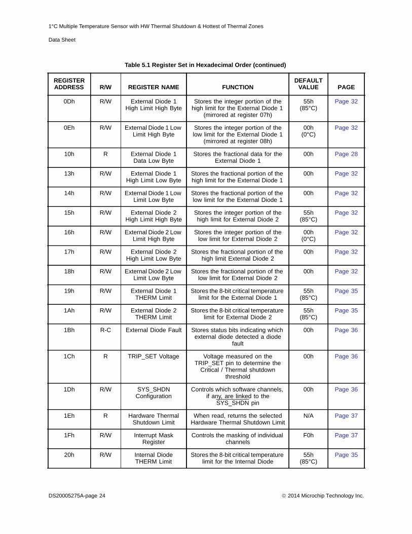
The registers shown in Table 5.1 are accessible through the SMBus. An entry of ‘-’ indicates that thebit is not used and will always read ‘0’.
Table 5.1 Register Set in Hexadecimal Order
REGISTERADDRESS R/W REGISTER NAME FUNCTION
DEFAULT VALUE PAGE
00h R Internal Diode Data High Byte
Stores the integer data for the Internal Diode
00h Page 28
01h R External Diode 1 Data High Byte
Stores the integer data for the External Diode 1
00h Page 28
02h R-C Status Stores the status bits for the Internal Diode and External Diodes
00h Page 30
03h R/W Configuration Controls the general operation of the device (mirrored at address
09h)
00h Page 30
04h R/W Conversion Rate Controls the conversion rate for updating temperature data (mirrored at address 0Ah)
06h(4/sec)
Page 31
05h R/W Internal Diode High Limit
Stores the 8-bit high limit for the Internal Diode (mirrored at address
0Bh)
55h (85°C)
Page 32
06h R/W Internal Diode Low Limit
Stores the 8-bit low limit for the Internal Diode (mirrored at address
0Ch)
00h(0°C)
Page 32
07h R/W External Diode 1 High Limit High Byte
Stores the integer portion of the high limit for the External Diode 1
(mirrored at register 0Dh)
55h (85°C)
Page 32
08h R/W External Diode 1 Low Limit High Byte
Stores the integer portion of the low limit for the External Diode 1
(mirrored at register 0Eh)
00h(0°C)
Page 32
09h R/W Configuration Controls the general operation of the device (mirrored at address
03h)
00h Page 30
0Ah R/W Conversion Rate Controls the conversion rate for updating temperature data (mirrored at address 04h)
06h(4/sec)
Page 31
0Bh R/W Internal Diode High Limit
Stores the 8-bit high limit for the Internal Diode (mirrored at address
05h)
55h (85°C)
Page 32
0Ch R/W Internal Diode Low Limit
Stores the 8-bit low limit for the Internal Diode (mirrored at address
06h)
00h(0°C)
Page 32
2014 Microchip Technology Inc. DS20005275A-page 23
1°C Multiple Temperature Sensor with HW Thermal Shutdown & Hottest of Thermal Zones
Data Sheet
0Dh R/W External Diode 1 High Limit High Byte
Stores the integer portion of the high limit for the External Diode 1
(mirrored at register 07h)
55h (85°C)
Page 32
0Eh R/W External Diode 1 Low Limit High Byte
Stores the integer portion of the low limit for the External Diode 1
(mirrored at register 08h)
00h(0°C)
Page 32
10h R External Diode 1 Data Low Byte
Stores the fractional data for the External Diode 1
00h Page 28
13h R/W External Diode 1 High Limit Low Byte
Stores the fractional portion of the high limit for the External Diode 1
00h Page 32
14h R/W External Diode 1 Low Limit Low Byte
Stores the fractional portion of the low limit for the External Diode 1
00h Page 32
15h R/W External Diode 2 High Limit High Byte
Stores the integer portion of the high limit for External Diode 2
55h(85°C)
Page 32
16h R/W External Diode 2 Low Limit High Byte
Stores the integer portion of the low limit for External Diode 2
00h(0°C)
Page 32
17h R/W External Diode 2 High Limit Low Byte
Stores the fractional portion of the high limit External Diode 2
00h Page 32
18h R/W External Diode 2 Low Limit Low Byte
Stores the fractional portion of the low limit for External Diode 2
00h Page 32
19h R/W External Diode 1 THERM Limit
Stores the 8-bit critical temperature limit for the External Diode 1
55h (85°C)
Page 35
1Ah R/W External Diode 2 THERM Limit
Stores the 8-bit critical temperature limit for External Diode 2
55h(85°C)
Page 35
1Bh R-C External Diode Fault Stores status bits indicating which external diode detected a diode
fault
00h Page 36
1Ch R TRIP_SET Voltage Voltage measured on the TRIP_SET pin to determine the
Critical / Thermal shutdown threshold
00h Page 36
1Dh R/W SYS_SHDN Configuration
Controls which software channels, if any, are linked to the
SYS_SHDN pin
00h Page 36
1Eh R Hardware Thermal Shutdown Limit
When read, returns the selected Hardware Thermal Shutdown Limit
N/A Page 37
1Fh R/W Interrupt Mask Register
Controls the masking of individual channels
F0h Page 37
20h R/W Internal Diode THERM Limit
Stores the 8-bit critical temperature limit for the Internal Diode
55h(85°C)
Page 35
Table 5.1 Register Set in Hexadecimal Order (continued)
REGISTERADDRESS R/W REGISTER NAME FUNCTION
DEFAULT VALUE PAGE
DS20005275A-page 24 2014 Microchip Technology Inc.

1°C Multiple Temperature Sensor with HW Thermal Shutdown & Hottest of Thermal Zones
Data Sheet
21h R/W THERM Hysteresis Stores the 8-bit hysteresis value that applies to all THERM limits
0Ah (10°C)
Page 35
22h R/W Consecutive ALERT Controls the number of out-of-limit conditions that must occur before
the status bit is asserted
70h Page 38
23h R External Diode 2 Data High Byte
Stores the integer data for External Diode 2
00h Page 28
24h R External Diode 2 Data Low Byte
Stores the fractional data for External Diode 2
00h Page 28
25h R External Diode 1 Beta Configuration
Stores the Beta Compensation circuitry settings for External Diode
1
08h Page 40
26h R/W External Diode 2 Beta Configuration
Stores the Beta Compensation circuitry settings for External Diode
2
08h Page 40
29h R Internal Diode Data Low Byte
Stores the fractional data for the Internal Diode
00h Page 28
2Ah R External Diode 3 High Byte
Stores the integer data for External Diode 3
00h Page 28
2Bh R External Diode 3 Low Byte
Stores the fractional data for External Diode 3
00h Page 28
2Ch R/W External Diode 3 High Limit High Byte
Stores the integer portion of the high limit for External Diode 3
55h (85°C)
Page 32
2Dh R/W External Diode 3 Low Limit High Byte
Stores the integer portion of the low limit for External Diode 3
00h(0°C)
Page 32
2Eh R/W External Diode 3 High Limit Low Byte
Stores the fractional portion of the high limit for External Diode 3
00h Page 32
2Fh R/W External Diode 3 Low Limit Low Byte
Stores the fractional portion of the low limit for External Diode 3
00h Page 32
30h R/W External Diode 3 THERM Limit
Stores the 8-bit critical temperature limit for External Diode 3
55h(85°C)
Page 35
32h R Hottest Diode High Byte
Stores the integer data for the hottest temperature
00h Page 41
33h R Hottest Diode Low Byte
Stores the fractional data for the hottest temperature
00h Page 41
34h R-C Hottest Status Status bits indicating which external diode is hottest
00h Page 41
35h R-C High Limit Status Status bits for the High Limits 00h Page 42
36h R-C Low Limit Status Status bits for the Low Limits 00h Page 43
Table 5.1 Register Set in Hexadecimal Order (continued)
REGISTERADDRESS R/W REGISTER NAME FUNCTION
DEFAULT VALUE PAGE
2014 Microchip Technology Inc. DS20005275A-page 25

1°C Multiple Temperature Sensor with HW Thermal Shutdown & Hottest of Thermal Zones
Data Sheet
37h R THERM Limit Status Status bits for the THERM Limits 00h Page 43
39h R/W REC Configuration Controls REC for all channels 00h Page 44
3Ah R/W Hottest Config Controls which external diode channels are used in the “hottest
of “comparison
00h Page 44
3Bh R/W Channel Config Controls which channels are enabled
00h Page 45
40h R/W Filter Control Controls the digital filter setting for the External Diode 1 channel
00h Page 46
41h R External Diode 4 Data High Byte
Stores the integer data for the External Diode 4 channel
00h Page 28
42h R External Diode 4 Data Low Byte
Stores the fractional data for the External Diode 4 channel
00h Page 28
43h R External Diode 5 Data High Byte
Stores the integer data for the External Diode 5 channel
00h Page 28
44h R External Diode 5 Data Low Byte
Stores the fractional data for the External Diode 5 channel
00h Page 28
45h R External Diode 6 Data High Byte
Stores the integer data for the External Diode 6 channel
00h Page 28
46h R External Diode 6 Data Low Byte
Stores the fractional data for the External Diode 6 channel
00h Page 28
47h R External Diode 7 Data High Byte
Stores the integer data for the External Diode 7 channel
00h Page 28
48h R External Diode 7 Data Low Byte
Stores the fractional data for the External Diode 7 channel
00h Page 28
50h R/W External Diode 4 High Limit High Byte
Stores the integer data for the high limit for the External Diode 4
channel
55h(85°C)
Page 32
51h R/W External Diode 4 Low Limit High Byte
Stores the integer data for the low limit for the External Diode 4
channel
00h(0°C)
Page 32
52h R/W External Diode 4 HIgh Limit Low Byte
Stores the fractional data for the low limit for the External Diode 4
channel
00h Page 32
53h R/W External Diode 4 Low Limit Low Byte
Stores the fractional data for the low limit for the External Diode 4
channel
00h Page 32
54h R/W External Diode 5 High Limit High Byte
Stores the integer data for the high limit for the External Diode 5
channel
55h(85°C)
Page 32
Table 5.1 Register Set in Hexadecimal Order (continued)
REGISTERADDRESS R/W REGISTER NAME FUNCTION
DEFAULT VALUE PAGE
DS20005275A-page 26 2014 Microchip Technology Inc.

1°C Multiple Temperature Sensor with HW Thermal Shutdown & Hottest of Thermal Zones
Data Sheet
55h R/W External Diode 5 Low Limit High Byte
Stores the integer data for the low limit for the External Diode 5
channel
00h(0°C)
Page 32
56h R/W External Diode 5 HIgh Limit Low Byte
Stores the fractional data for the low limit for the External Diode 5
channel
00h Page 32
57h R/W External Diode 5 Low Limit Low Byte
Stores the fractional data for the low limit for the External Diode 5
channel
00h Page 32
58h R/W External Diode 6 High Limit High Byte
Stores the integer data for the high limit for the External Diode 6
channel
55h(85°C)
Page 32
59h R/W External Diode 6 Low Limit High Byte
Stores the integer data for the low limit for the External Diode 6
channel
00h(0°C)
Page 32
5Ah R/W External Diode 6 HIgh Limit Low Byte
Stores the fractional data for the low limit for the External Diode 6
channel
00h(0°C)
Page 32
5Bh R/W External Diode 6 Low Limit Low Byte
Stores the fractional data for the low limit for the External Diode 6
channel
00h(0°C)
Page 32
5Ch R/W External Diode 7 High Limit High Byte
Stores the integer data for the high limit for the External Diode 7
channel
55h(85°C)
Page 32
5Dh R/W External Diode 7 Low Limit High Byte
Stores the integer data for the low limit for the External Diode 7
channel
00h(0°C)
Page 32
5Eh R/W External Diode 7 HIgh Limit Low Byte
Stores the fractional data for the low limit for the External Diode 7
channel
00h Page 32
5Fh R/W External Diode 7 Low Limit Low Byte
Stores the fractional data for the low limit for the External Diode 7
channel
00h Page 32
64h R/W External Diode 4 THERM Limit
Stores the 8-bit critical temperature limit for External Diode 4
55h(85°C)
Page 32
65h R/W External Diode 5 THERM Limit
Stores the 8-bit critical temperature limit for External Diode 5
55h(85°C)
Page 32
66h R/W External Diode 6 THERM Limit
Stores the 8-bit critical temperature limit for External Diode 6
55h(85°C)
Page 32
67h R/W External Diode 7 THERM Limit
Stores the 8-bit critical temperature limit for External Diode 7
55h(85°C)
Page 32
Table 5.1 Register Set in Hexadecimal Order (continued)
REGISTERADDRESS R/W REGISTER NAME FUNCTION
DEFAULT VALUE PAGE
2014 Microchip Technology Inc. DS20005275A-page 27

1°C Multiple Temperature Sensor with HW Thermal Shutdown & Hottest of Thermal Zones
Data Sheet
5.1 Data Read InterlockWhen any temperature channel high byte register is read, the corresponding low byte is copied intoan internal ‘shadow’ register. The user is free to read the low byte at any time and be guaranteed thatit will correspond to the previously read high byte. Regardless if the low byte is read or not, readingfrom the same high byte register again will automatically refresh this stored low byte data.
5.2 Temperature Data Registers
71h R/W External Diode 4 Beta Configuration
Stores the Beta Compensation circuitry settings for External Diode
4
08h Page 40
72h R/W External Diode 6 Beta Configuration
Stores the Beta Compensation circuitry settings for External Diode
6
08h Page 40
FDh R Product ID - EMC1428
Stores a fixed value that identifies each product
29h Page 46
FEh R Manufacturer ID Stores a fixed value that represents Microchip
5Dh Page 46
FFh R Revision Stores a fixed value that represents the revision number
01h Page 47
Table 5.2 Temperature Data Registers
ADDR R/W REGISTER B7 B6 B5 B4 B3 B2 B1 B0 DEFAULT
00h R Internal Diode High Byte
Sign 64 32 16 8 4 2 1 00h
29h R Internal Diode Low Byte
0.5 0.25 0.125 - - - - - 00h
01h R External Diode 1 High Byte
Sign 64 32 16 8 4 2 1 00h
10h R External Diode 1 Low Byte
0.5 0.25 0.125 - - - - - 00h
23h R External Diode 2 High Byte
Sign 64 32 16 8 4 2 1 00h
24h R External Diode 2 Low Byte
0.5 0.25 0.125 - - - - - 00h
2Ah R External Diode 3 High Byte
Sign 64 32 16 8 4 2 1 00h
2Bh R External Diode 3 Low Byte
0.5 0.25 0.125 - - - - - 00h
Table 5.1 Register Set in Hexadecimal Order (continued)
REGISTERADDRESS R/W REGISTER NAME FUNCTION
DEFAULT VALUE PAGE
DS20005275A-page 28 2014 Microchip Technology Inc.

1°C Multiple Temperature Sensor with HW Thermal Shutdown & Hottest of Thermal Zones
Data Sheet
All temperatures are stored as an 11-bit value with the high byte representing the integer value andthe low byte representing the fractional value left justified to occupy the MSBits. The data format isstandard 2’s complement from -64°C to 127.875°C as shown in Table 5.3.
41h R External Diode 4 High Byte
Sign 64 32 16 8 4 2 1 00h
42h R External Diode 4 Low Byte
0.5 0.25 0.125 - - - - - 00h
43h R External Diode 5 High Byte
Sign 64 32 16 8 4 2 1 00h
44h R External Diode 5 Low Byte
0.5 0.25 0.125 - - - - - 00h
45h R External Diode 6 High Byte
Sign 64 32 16 8 4 2 1 00h
46h R External Diode 6 Low Byte
0.5 0.25 0.125 - - - - - 00h
47h R External Diode 7 High Byte
Sign 64 32 16 8 4 2 1 00h
48h R External Diode 7 Low Byte
0.5 0.25 0.125 - - - - - 00h
Table 5.3 Temperature Data Format
TEMPERATURE (°C) BINARY HEX (AS READ BY
REGISTERS)
Diode Fault 1000_0000_000b 80_00h
-64 1100_0000_000b C0_00h
-63.875 1100_0000_001b C0_20h
-1 1111_1111_000b FF_00h
-0.125 1111_1111_111b FF_E0h
0 0000_0000_000b 00_00h
0.125 0000_0000_001b 00_20h
1 0000_0001_000b 01_00h
63 0011_1111_000b 3F_00h
64 0100_0000_000b 40_00h
127 0111_1111_000b 7F_00h
127.875 0111_1111_111b 7F_E0h
Table 5.2 Temperature Data Registers (continued)
ADDR R/W REGISTER B7 B6 B5 B4 B3 B2 B1 B0 DEFAULT
2014 Microchip Technology Inc. DS20005275A-page 29
1°C Multiple Temperature Sensor with HW Thermal Shutdown & Hottest of Thermal Zones
Data Sheet
AD T
0
0
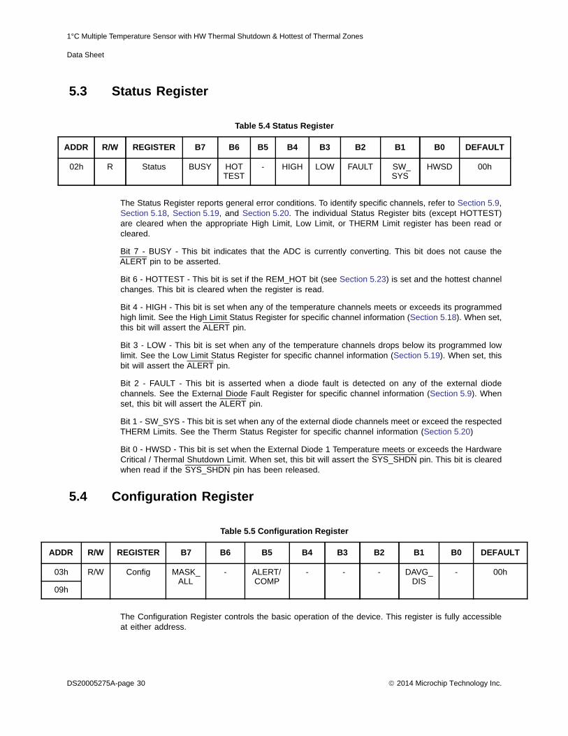
5.3 Status Register
The Status Register reports general error conditions. To identify specific channels, refer to Section 5.9,Section 5.18, Section 5.19, and Section 5.20. The individual Status Register bits (except HOTTEST)are cleared when the appropriate High Limit, Low Limit, or THERM Limit register has been read orcleared.
Bit 7 - BUSY - This bit indicates that the ADC is currently converting. This bit does not cause theALERT pin to be asserted.
Bit 6 - HOTTEST - This bit is set if the REM_HOT bit (see Section 5.23) is set and the hottest channelchanges. This bit is cleared when the register is read.
Bit 4 - HIGH - This bit is set when any of the temperature channels meets or exceeds its programmedhigh limit. See the High Limit Status Register for specific channel information (Section 5.18). When set,this bit will assert the ALERT pin.
Bit 3 - LOW - This bit is set when any of the temperature channels drops below its programmed lowlimit. See the Low Limit Status Register for specific channel information (Section 5.19). When set, thisbit will assert the ALERT pin.
Bit 2 - FAULT - This bit is asserted when a diode fault is detected on any of the external diodechannels. See the External Diode Fault Register for specific channel information (Section 5.9). Whenset, this bit will assert the ALERT pin.
Bit 1 - SW_SYS - This bit is set when any of the external diode channels meet or exceed the respectedTHERM Limits. See the Therm Status Register for specific channel information (Section 5.20)
Bit 0 - HWSD - This bit is set when the External Diode 1 Temperature meets or exceeds the HardwareCritical / Thermal Shutdown Limit. When set, this bit will assert the SYS_SHDN pin. This bit is clearedwhen read if the SYS_SHDN pin has been released.
5.4 Configuration Register
The Configuration Register controls the basic operation of the device. This register is fully accessibleat either address.
Table 5.4 Status Register
ADDR R/W REGISTER B7 B6 B5 B4 B3 B2 B1 B0 DEFAULT
02h R Status BUSY HOTTEST
- HIGH LOW FAULT SW_SYS
HWSD 00h
Table 5.5 Configuration Register
DR R/W REGISTER B7 B6 B5 B4 B3 B2 B1 B0 DEFAUL
3h R/W Config MASK_ALL
- ALERT/COMP
- - - DAVG_DIS
- 00h
9h
DS20005275A-page 30 2014 Microchip Technology Inc.

1°C Multiple Temperature Sensor with HW Thermal Shutdown & Hottest of Thermal Zones
Data Sheet
Bit 7 - MASK_ALL - Masks the ALERT pin from asserting.
‘0’ (default) - The ALERT pin is not masked. If any of the appropriate status bits are set the ALERT pin will be asserted.
‘1’ - The ALERT pin is masked. It will not be asserted for any interrupt condition. The Status Registers will be updated normally.
Bit 5 - ALERT/COMP - Controls the operation of the ALERT pin.
‘0’ (default) - The ALERT pin acts as described in Section 4.1.1.
‘1’ - The ALERT pin acts in comparator mode as described in Section 4.1.2. In this mode the MASK_ALL bit is ignored.
Bit 1 - DAVG_DIS - Disables the dynamic averaging feature on all temperature channels (seeSection 4.5.6).
‘0’ (default) - The dynamic averaging feature is enabled. All temperature channels will be converted with an averaging factor that is based on the conversion rate as shown in Table 4.2.
‘1’ - The dynamic averaging feature is disabled. All temperature channels will be converted with a maximum averaging factor of 1x (equivalent to 11-bit conversion). For higher conversion rates (i.e. more conversions per second), this averaging factor will be reduced as shown in Table 4.2.
5.5 Conversion Rate Register
The Conversion Rate Register controls how often the temperature measurement channels are updatedand compared against the limits. This register is fully accessible at either address.
Bits 3-0 - CONV[3:0] - Determines the conversion rate as shown in Table 5.7.
The actual conversion rate for Continuous conversions will depend on the number of diode channelsenabled and is shown in Table 5.8.
Table 5.6 Conversion Rate Register
ADDR R/W REGISTER B7 B6 B5 B4 B3 B2 B1 B0 DEFAULT
04h R/W Conversion Rate
- - - - CONV[2:0] 06h(4/sec)
0Ah
Table 5.7 Conversion Rate
CONV[2:0]
CONVERSIONS / SECOND2 1 0
1 0 0 1
1 0 1 2
1 1 0 4 (default)
1 1 1 Continuous
All Others 4
2014 Microchip Technology Inc. DS20005275A-page 31

1°C Multiple Temperature Sensor with HW Thermal Shutdown & Hottest of Thermal Zones
Data Sheet
5.6 Limit Registers
Table 5.8 Maximum Conversion Rate Per Temperature Channels
NUMBER OF EXTERNAL DIODE CHANNELS MAX CONVERSION RATE
4 12 / sec
5 11 / sec
6 10 / sec
7 9 / sec
Table 5.9 Temperature Limit Registers
ADDR. R/W REGISTER B7 B6 B5 B4 B3 B2 B1 B0 DEFAULT
05h R/W Internal Diode High Limit
Sign 64 32 16 8 4 2 1 55h(85°C)
0Bh
06h R/W Internal Diode Low Limit
Sign 64 32 16 8 4 2 1 00h(0°C)
0Ch
07h R/W External Diode 1 High
Limit High Byte
Sign 64 32 16 8 4 2 1 55h(85°C)
0Dh
13h R/W External Diode 1 High
Limit Low Byte
0.5 0.25 0.125 - - - - - 00h
08h R/W External Diode 1 Low
Limit High Byte
Sign 64 32 16 8 4 2 1 00h(0°C)
0Eh
14h R/W External Diode 1 Low
Limit Low Byte
0.5 0.25 0.125 - - - - - 00h
15h R/W External Diode 2 High
Limit High Byte
Sign 64 32 16 8 4 2 1 55h(85°C)
16h R/W External Diode 2 Low
Limit High Byte
Sign 64 32 16 8 4 2 1 00h(0°C)
DS20005275A-page 32 2014 Microchip Technology Inc.

1°C Multiple Temperature Sensor with HW Thermal Shutdown & Hottest of Thermal Zones
Data Sheet
17h R/W External Diode 2 High
Limit Low Byte
0.5 0.25 0.125 - - - - - 00h
18h R/W External Diode 2 Low
Limit Low Byte
0.5 0.25 0.125 - - - - - 00h
2Ch R/W External Diode 3 High
Limit High Byte
Sign 64 32 16 8 4 2 1 55h(85°C)
2Dh R/W External Diode 3 Low
Limit High Byte
Sign 64 32 16 8 4 2 1 00h(0°C)
2Eh R/W External Diode 3 High
Limit Low Byte
0.5 0.25 0.125 - - - - - 00h
2Fh R/W External Diode 3 Low
Limit Low Byte
0.5 0.25 0.125 - - - - - 00h
50h R/W External Diode 4 High
Limit High Byte
Sign 64 32 16 8 4 2 1 55h(85°C)
51h R/W External Diode 4 Low
Limit High Byte
Sign 64 32 16 8 4 2 1 00h(0°C)
52h R/W External Diode 4 High
Limit Low Byte
0.5 0.25 0.125 - - - - - 00h
53h R/W External Diode 4 Low
Limit Low Byte
0.5 0.25 0.125 - - - - - 00h
54h R/W External Diode 5 High
Limit High Byte
Sign 64 32 16 8 4 2 1 55h(85°C)
55h R/W External Diode 5 Low
Limit High Byte
Sign 64 32 16 8 4 2 1 00h(0°C)
Table 5.9 Temperature Limit Registers (continued)
ADDR. R/W REGISTER B7 B6 B5 B4 B3 B2 B1 B0 DEFAULT
2014 Microchip Technology Inc. DS20005275A-page 33

1°C Multiple Temperature Sensor with HW Thermal Shutdown & Hottest of Thermal Zones
Data Sheet
The device contains both high and low limits for all temperature channels. If the measured temperaturemeets or exceeds the high limit, then the corresponding status bit is set and the ALERT pin is asserted.Likewise, if the measured temperature is less than the low limit, the corresponding status bit is set andthe ALERT pin is asserted.
The limit registers with multiple addresses are fully accessible at either address.
56h R/W External Diode 5 High
Limit Low Byte
0.5 0.25 0.125 - - - - - 00h
57h R/W External Diode 5 Low
Limit Low Byte
0.5 0.25 0.125 - - - - - 00h
58h R/W External Diode 6 High
Limit High Byte
Sign 64 32 16 8 4 2 1 55h(85°C)
59h R/W External Diode 6 Low
Limit High Byte
Sign 64 32 16 8 4 2 1 00h(0°C)
5Ah R/W External Diode 6 High
Limit Low Byte
0.5 0.25 0.125 - - - - - 00h
5Bh R/W External Diode 6 Low
Limit Low Byte
0.5 0.25 0.125 - - - - - 00h
5Ch R/W External Diode 7 High
Limit High Byte
Sign 64 32 16 8 4 2 1 55h(85°C)
5Dh R/W External Diode 7 Low
Limit High Byte
Sign 64 32 16 8 4 2 1 00h(0°C)
5Eh R/W External Diode 7 High
Limit Low Byte
0.5 0.25 0.125 - - - - - 00h
5Fh R/W External Diode 7 Low
Limit Low Byte
0.5 0.25 0.125 - - - - - 00h
Table 5.9 Temperature Limit Registers (continued)
ADDR. R/W REGISTER B7 B6 B5 B4 B3 B2 B1 B0 DEFAULT
DS20005275A-page 34 2014 Microchip Technology Inc.

1°C Multiple Temperature Sensor with HW Thermal Shutdown & Hottest of Thermal Zones
Data Sheet
5.7 Therm Hysteresis Register
The THERM Hysteresis is used in conjunction with the THERM Limit Registers to assert theSYS_SHDN pin. In addition, the THERM Hysteresis Register is used with the High Limit Registerswhen the ALERT pin is configured to act as a comparator (see Section 4.1.2).
5.8 Therm Limit Registers
The THERM Limit Registers are used to set the threshold for the software inputs to the Critical /Thermal Shutdown circuitry. If the measured channel is linked to the Critical / Thermal Shutdowncircuitry and meets or exceeds this limit, then the SYS_SHDN pin will be asserted.
Table 5.10 Therm Hysteresis Register
ADDR. R/W REGISTER B7 B6 B5 B4 B3 B2 B1 B0 DEFAULT
21h R/W THERM Hysteresis
- 64 32 16 8 4 2 1 0Ah(10°C)
Table 5.11 Therm Limit Registers
ADDR. R/W REGISTER B7 B6 B5 B4 B3 B2 B1 B0 DEFAULT
19h R/W External Diode 1
THERM Limit
Sign 64 32 16 8 4 2 1 55h(85°C)
1Ah R/W External Diode 2
THERM Limit
Sign 64 32 16 8 4 2 1 55h(85°C)
20h R/W Internal Diode THERM Limit
Sign 64 32 16 8 4 2 1 55h(85°C)
30h R/W External Diode 3
THERM Limit
Sign 64 32 16 8 4 2 1 55h(85°C)
64h R/W External Diode 4
THERM Limit
Sign 64 32 16 8 4 2 1 55h(85°C)
65h R/W External Diode 5
THERM Limit
Sign 64 32 16 8 4 2 1 55h(85°C)
66h R/W External Diode 6
THERM Limit
Sign 64 32 16 8 4 2 1 55h(85°C)
67h R/W External Diode 7
THERM Limit
Sign 64 32 16 8 4 2 1 55h(85°C)
2014 Microchip Technology Inc. DS20005275A-page 35

1°C Multiple Temperature Sensor with HW Thermal Shutdown & Hottest of Thermal Zones
Data Sheet
A
A
5.9 External Diode Fault Register
The External Diode Fault Register indicates which of the external diodes caused the FAULT bit in theStatus Register to be set. These bits are cleared when read if the error condition has been removed.
Bit 7 - E7FLT - This bit is set if the External Diode 7 channel reported a diode fault.
Bit 6 - E6FLT - This bit is set if the External Diode 6 channel reported a diode fault.
Bit 5 - E5FLT - This bit is set if the External Diode 5 channel reported a diode fault.
Bit 4 - E4FLT - This bit is set if the External Diode 4 channel reported a diode fault.
Bit 3 - E3FLT - This bit is set if the External Diode 3 channel reported a diode fault.
Bit 2 - E2FLT - This bit is set if the External Diode 2 channel reported a diode fault.
Bit 1 - E1FLT - This bit is set if the External Diode 1 channel reported a diode fault.
5.10 TRIP_SET Reading Register
The TRIP_SET Reading Register stores the voltage measured on the TRIP_SET pin. The bit weightingrepresents mV above 0V.
5.11 Software Thermal Shutdown Configuration Register
The Software Thermal Shutdown Configuration Register controls whether any of the software channelswill assert the SYS_SHDN pin. If a channel is enabled, the temperature is compared against the
Table 5.12 External Diode Fault Register
DDR R/W REGISTER B7 B6 B5 B4 B3 B2 B1 B0 DEFAULT
1Bh R-C External Diode Fault
E7FLT E6FLT E5FLT E4FLT E3FLT E2FLT E1FLT - 00h
Table 5.13 TRIP_SET Reading Register
ADDR R/W REGISTER B7 B6 B5 B4 B3 B2 B1 B0 DEFAULT
1Ch R TRIP_SET Reading
752.9 376.5 188.2 94.12 47.1 23.53 11.76 5.88 00h
Table 5.14 Software Thermal Shutdown Configuration Register
DDR R/W REGISTER B7 B6 B5 B4 B3 B2 B1 B0 DEFAULT
1Dh R/W Software Thermal Shutdown
Configuration
E7 SYS
E6 SYS
E5 SYS
E4 SYS
E3 SYS
E2 SYS
E1 SYS
INT SYS
00h
DS20005275A-page 36 2014 Microchip Technology Inc.

1°C Multiple Temperature Sensor with HW Thermal Shutdown & Hottest of Thermal Zones
Data Sheet
ADDR ULT
1Fh h
corresponding THERM Limit. If the measured temperature meets or exceeds the THERM Limit, thenthe SYS_SHDN pin is asserted. This functionality is in addition to the Hardware Shutdown circuitry.
Bits 7-1 - ExSYS - configures the External Diode X channel to assert the SYS_SHDN pin based onit’s respective THERM Limit (see Section 5.20 for details on the ExTHERM status bits).
‘0’ (default) - the External Diode X channel is not linked to the SYS_SHDN pin. If the temperature meets or exceeds it’s THERM Limit, the ExTHERM status bit is set but the SYS_SHDN pin is not asserted.
‘1’ - the External Diode X channel is linked to the SYS_SHDN pin. If the temperature meets or exceeds it’s THERM Limit, the ExTHERM status bit is set and the SYS_SHDN pin is asserted. It will remain asserted until the temperature drops below it’s THERM Limit minus the THERM Hysteresis.
Bit 0 - INTSYS - configures the Internal Diode channel to assert the SYS_SHDN pin based on it’srespective THERM Limit (see Section 5.20 for details on the ITHERM status bit).
‘0’ (default) - the Internal Diode channel is not linked to the SYS_SHDN pin. If the temperature meets or exceeds it’s THERM Limit, the ITHERM status bit is set but the SYS_SHDN pin is not asserted.
‘1’ - the Internal Diode channel is linked to the SYS_SHDN pin. If the temperature meets or exceeds it’s THERM Limit, the ITHERM status bit is set and the SYS_SHDN pin is asserted. It will remain asserted until the temperature drops below it’s THERM Limit minus the THERM Hysteresis.
5.12 Hardware Critical / Thermal Shutdown Limit Register
This read only register returns the Hardware Thermal Shutdown Limit selected by the TRIP_SETvoltage. The data represents the hardware set temperature in °C. See Table 5.2 for the data format.
When the External Diode 1 Temperature meets or exceeds this limit, the SYS_SHDN pin is assertedand will remain asserted until the External Diode 1 Temperature drops below this limit minus 10°C.
5.13 Channel Interrupt Mask Register
The Channel Interrupt Mask Register controls individual channel masking. When a channel is masked,the ALERT pin will not be asserted when the masked channel reads a diode fault or out of limit error.The channel mask does not mask the SYS_SHDN pin.
Table 5.15 Hardware Thermal Shutdown Limit Register
ADDR R/W REGISTER B7 B6 B5 B4 B3 B2 B1 B0 DEFAULT
1Eh R Hardware Thermal
Shutdown Limit
- 64 32 16 8 4 2 1 N/A
Table 5.16 Channel Interrupt Mask Register
R/W REGISTER B7 B6 B5 B4 B3 B2 B1 B0 DEFA
R/W Channel Mask
E7_ MSK
E6_ MSK
E5_ MSK
E4_ MSK
E3_ MSK
E2_ MSK
E1_ MSK
INT_ MSK
F0
2014 Microchip Technology Inc. DS20005275A-page 37

1°C Multiple Temperature Sensor with HW Thermal Shutdown & Hottest of Thermal Zones
Data Sheet
Bits 7-4 - Ex_MSK - Prevents the ALERT pin from being asserted when the External Diode X channelis out of limit or reports a diode fault. If the EXT6_APD bit is not set (see Section 5.23), then theEXT7_MSK bit is ignored. Likewise, if the EXT4_APD bit is not set, then the EXT5_MSK bit is ignored.
‘0’ - The External Diode X channel will cause the ALERT pin to be asserted if it is out of limit or reports a diode fault.
‘1’ (default) - The External Diode X channel will not cause the ALERT pin to be asserted if it is out of limit or reports a diode fault.
Bits 3-1- Ex_MSK - Prevents the ALERT pin from being asserted when the External Diode X channelis out of limit or reports a diode fault. If the EXT2_APD bit is not set (see Section 5.23), then theEXT3_MSK bit is ignored.
‘0’ - (default) The External Diode X channel will cause the ALERT pin to be asserted if it is out of limit or reports a diode fault.
‘1’ - The External Diode X channel will not cause the ALERT pin to be asserted if it is out of limit or reports a diode fault.
Bit 0 - INT_MSK- Prevents the ALERT pin from being asserted when the Internal Diode temperatureis out of limit.
‘0’ (default) - The Internal Diode channel will cause the ALERT pin to be asserted if it is out of limit.
‘1’ - The Internal Diode channel will not cause the ALERT pin to be asserted if it is out of limit.
5.14 Consecutive ALERT Register
The Consecutive ALERT Register determines how many times an out-of-limit error or diode fault mustbe detected in consecutive measurements before the interrupt status registers are asserted.
Each out of limit error and diode fault condition has its own counter associated with it. Each counteris incremented whenever the corresponding channel exceeds the appropriate limit. Additionally, eachcounter is reset if the condition has been removed. (i.e. if External Diode 1 exceeds its high limit, itwill increment the high counter. If, on the next measurement, it experiences a diode fault, the high limitcounter will be reset and the diode fault counter will be incremented).
When the ALERT pin is configured as an interrupt and the consecutive alert counter reaches itsprogrammed value then the STATUS bit(s) for that channel and the error condition will be set to ‘1’and the ALERT pin will be asserted. Measurements will continue normally.
When the ALERT pin is configured as a comparator, the consecutive alert counter will ignore diodefault and low limit errors and only increment if the measured temperature meets or exceeds the HighLimit. Additionally, once the consecutive alert counter reaches the programmed limit, the ALERT pinwill be asserted, but the counter will not be reset. It will remain set until the temperature drops belowthe High Limit minus the THERM Hysteresis value.
For example, if the CALRT[2:0] bits are set for 4 consecutive alerts on an EMC1428 device, the highlimits are set at 70°C, and none of the channels are masked, then the status bits will be asserted afterthe following four measurements:
Table 5.17 Consecutive ALERT Register
ADDR. R/W REGISTER B7 B6 B5 B4 B3 B2 B1 B0 DEFAULT
22h R/W Consecutive ALERT
TIMEOUT
CTHERM2
CTHERM1
CTHERM0
CALRT2
CALRT1
CALRT0
- 70h
DS20005275A-page 38 2014 Microchip Technology Inc.

1°C Multiple Temperature Sensor with HW Thermal Shutdown & Hottest of Thermal Zones
Data Sheet
1. Internal Diode reads 71°C and both external diodes read 69°C. Consecutive alert counter for INTis incremented to 1.
2. Both the Internal Diode and the External Diode 1 read 71°C and External Diode 2 reads 68°C.Consecutive alert counter for INT is incremented to 2 and for EXT1 is set to 1.
3. The External Diode 1 reads 71°C and both the Internal Diode and External Diode 2 read 69°C.Consecutive alert counter for INT and EXT2 are cleared and EXT1 is incremented to 2.
4. The Internal Diode reads 71°C and both external diodes read 71°C. Consecutive alert counter forINT is set to 1, EXT2 is set to 1, and EXT1 is incremented to 3.
5. The Internal Diode reads 71°C and both the external diodes read 71°C. Consecutive alert counterfor INT is incremented to 2, EXT2 is set to 2, and EXT1 is incremented to 4. The HIGH status bitare set for EXT1 and the ALERT pin is asserted. The EXT1 counter is reset to 0 and all othercounters hold the last value until the next temperature measurement.
Bit 7 - TIMEOUT - Determines whether the SMBus Timeout function is enabled.
‘0’ (default) - The SMBus Timeout feature is disabled. The SMCLK line can be held low indefinitely without the device resetting its SMBus protocol.
‘1’ - The SMBus Timeout feature is enabled. If the SMCLK line is held low for more than 30ms, then the device will reset the SMBus protocol.
Bits 6-4 CTHRM[2:0] - Determines the number of consecutive measurements that must exceed thecorresponding THERM Limit and Hardware Thermal Shutdown Limit before the SYS_SHDN pin isasserted. All temperature channels use this value to set the respective counters. The consecutiveTHERM counter is incremented whenever any of the measurements exceed the correspondingTHERM Limit or if the External Diode 1 measurement meets or exceeds the Hardware ThermalShutdown Limit.
If the temperature drops below the THERM limit or Hardware Thermal Shutdown Limit, then thecounter is reset. If the programmed number of consecutive measurements exceed the THERM Limitor Hardware Thermal Shutdown Limit, and the appropriate channel is linked to the SYS_SHDN pin,then the SYS_SHDN pin will be asserted low.
Once the SYS_SHDN pin is asserted, the consecutive THERM counter will not reset until thecorresponding temperature drops below the appropriate limit minus the corresponding hysteresis.
The bits are decoded as shown in Table 5.18. The default setting is 4 consecutive out of limitconversions.
Bits 3-1 - CALRT[2:0] - Determine the number of consecutive measurements that must have an out oflimit condition or diode fault before the STATUS bits is asserted. All temperature channels use thisvalue to set the respective counters. The bits are decoded as shown in Table 5.18. The default settingis 1 consecutive out of limit conversion.
APPLICATION NOTE: If one of the fault queues is not cleared and the CALRT[2:0] (or CTHRM[2:0]) bits areupdated, the update won’t take affect until fault queue is cleared. All the fault queues areindependent so those that are empty will be updated immediately.
Table 5.18 Consecutive Alert Settings
2 1 0NUMBER OF CONSECUTIVE OUT OF LIMIT
MEASUREMENTS
0 0 0 1 (default for CALRT[2:0])
0 0 1 2
2014 Microchip Technology Inc. DS20005275A-page 39
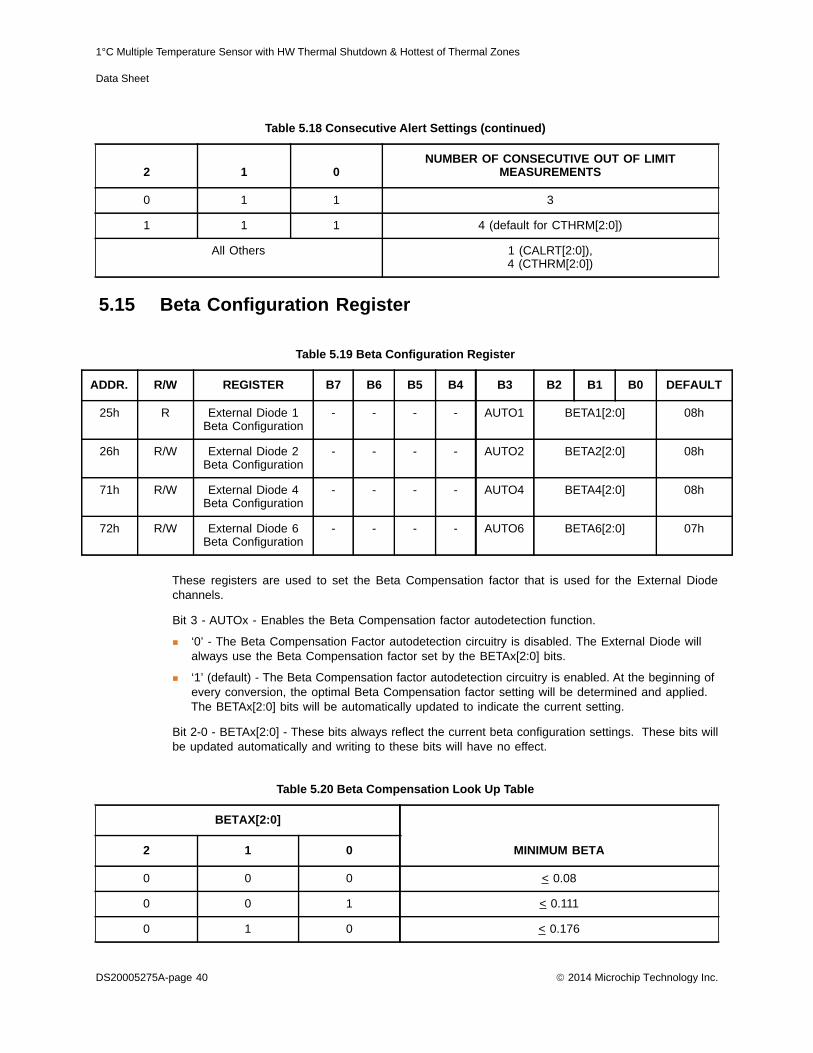
1°C Multiple Temperature Sensor with HW Thermal Shutdown & Hottest of Thermal Zones
Data Sheet
5.15 Beta Configuration Register
These registers are used to set the Beta Compensation factor that is used for the External Diodechannels.
Bit 3 - AUTOx - Enables the Beta Compensation factor autodetection function.
‘0’ - The Beta Compensation Factor autodetection circuitry is disabled. The External Diode will always use the Beta Compensation factor set by the BETAx[2:0] bits.
‘1’ (default) - The Beta Compensation factor autodetection circuitry is enabled. At the beginning of every conversion, the optimal Beta Compensation factor setting will be determined and applied. The BETAx[2:0] bits will be automatically updated to indicate the current setting.
Bit 2-0 - BETAx[2:0] - These bits always reflect the current beta configuration settings. These bits willbe updated automatically and writing to these bits will have no effect.
0 1 1 3
1 1 1 4 (default for CTHRM[2:0])
All Others 1 (CALRT[2:0]), 4 (CTHRM[2:0])
Table 5.19 Beta Configuration Register
ADDR. R/W REGISTER B7 B6 B5 B4 B3 B2 B1 B0 DEFAULT
25h R External Diode 1 Beta Configuration
- - - - AUTO1 BETA1[2:0] 08h
26h R/W External Diode 2 Beta Configuration
- - - - AUTO2 BETA2[2:0] 08h
71h R/W External Diode 4 Beta Configuration
- - - - AUTO4 BETA4[2:0] 08h
72h R/W External Diode 6 Beta Configuration
- - - - AUTO6 BETA6[2:0] 07h
Table 5.20 Beta Compensation Look Up Table
BETAX[2:0]
MINIMUM BETA2 1 0
0 0 0 < 0.08
0 0 1 < 0.111
0 1 0 < 0.176
Table 5.18 Consecutive Alert Settings (continued)
2 1 0NUMBER OF CONSECUTIVE OUT OF LIMIT
MEASUREMENTS
DS20005275A-page 40 2014 Microchip Technology Inc.

1°C Multiple Temperature Sensor with HW Thermal Shutdown & Hottest of Thermal Zones
Data Sheet
5.16 Hottest Temperature Registers
The Hottest Temperature Registers store the measured hottest temperature of all the selected externaldiode channels (see Section 5.22). If no External diodes are selected then the High Byte Register willread 80h. The data format is the same as the temperature channels.
5.17 Hottest Temperature Status Register
The Hottest Temperature Status Register flags which external diode temperature is hottest. If multipletemperature channels measure the same temperature and are equal to the hottest temperature, thenhottest status will be based on the measurement order.
Bit 7 - EXT7 - The External Diode 7 channel is the hottest.
Bit 6 - EXT6 - The External Diode 6 channel is the hottest.
Bit 4 - EXT5 - The External Diode 5 channel is the hottest.
0 1 1 < 0.29
1 0 0 < 0.48
1 0 1 < 0.9
1 1 0 < 2.33
1 1 1 Disabled
Table 5.21 Hottest Temperature Registers
ADDR R/W REGISTER B7 B6 B5 B4 B3 B2 B1 B0 DEFAULT
32h R Hottest Temperature
High Byte
Sign 64 32 16 8 4 2 1 80h
33h R Hottest Temperature
Low Byte
0.5 0.25 0.125 - - - - - 00h
Table 5.22 Hottest Temperature Register
ADDR R/W REGISTER B7 B6 B5 B4 B3 B2 B1 B0 DEFAULT
34h R Hottest Temperature
Status
EXT7 EXT6 EXT5 EXT4 EXT3 EXT2 EXT1 INT 00h
Table 5.20 Beta Compensation Look Up Table (continued)
BETAX[2:0]
MINIMUM BETA2 1 0
2014 Microchip Technology Inc. DS20005275A-page 41

1°C Multiple Temperature Sensor with HW Thermal Shutdown & Hottest of Thermal Zones
Data Sheet
A
Bit 3 - EXT4 - The External Diode 4 channel is the hottest.
Bit 3 - EXT3 - The External Diode 3 channel is the hottest.
Bit 2 - EXT2 - The External Diode 2 channel is the hottest.
Bit 1 - EXT1 - The External Diode 1 channel is the hottest.
Bit 0 - INT - The Internal Diode channel is the hottest.
5.18 High Limit Status Register
The High Limit Status Register contains the status bits that are set when a temperature channel highlimit is exceeded for a number of consecutive readings as set by the consecutive alert counts (seeSection 5.14). If any of these bits are set, then the HIGH status bit in the Status Register is set.Reading from the High Limit Status Register will clear all bits if the error condition has been removed.Reading from the register will also clear the HIGH status bit in the Status Register.
The ALERT pin will be set if any of these status bits are set.
Bit 7 - E7HIGH - This bit is set when the External Diode 7 channel meets or exceeds its programmedhigh limit.
Bit 6 - E6HIGH - This bit is set when the External Diode 6 channel meets or exceeds its programmedhigh limit.
Bit 5 - E5HIGH - This bit is set when the External Diode 5 channel meets or exceeds its programmedhigh limit.
Bit 4 - E4HIGH - This bit is set when the External Diode 4 channel meets or exceeds its programmedhigh limit.
Bit 3 - E3HIGH - This bit is set when the External Diode 3 channel meets or exceeds its programmedhigh limit.
Bit 2 - E2HIGH - This bit is set when the External Diode 2 channel meets or exceeds its programmedhigh limit.
Bit 1 - E1HIGH - This bit is set when the External Diode 1 channel meets or exceeds its programmedhigh limit.
Bit 0 - IHIGH - This bit is set when the Internal Diode channel meets or exceeds its programmed highlimit.
Table 5.23 High Limit Status Register
DDR R/W REGISTER B7 B6 B5 B4 B3 B2 B1 B0 DEFAULT
35h R-C High Limit Status
E7 HIGH
E6 HIGH
E5 HIGH
E4 HIGH
E3 HIGH
E2 HIGH
E1 HIGH
I HIGH
00h
DS20005275A-page 42 2014 Microchip Technology Inc.

1°C Multiple Temperature Sensor with HW Thermal Shutdown & Hottest of Thermal Zones
Data Sheet
ADDR AULT
37h 00h
5.19 Low Limit Status Register
The Low Limit Status Register contains the status bits that are set when a temperature channel dropsbelow the low limit for a number of consecutive readings as set by the consecutive alert counts (seeSection 5.14). If any of these bits are set, then the LOW status bit in the Status Register is set. Readingfrom the Low Limit Status Register will clear all bits if the error condition has been removed. Readingfrom the register will also clear the LOW status bit in the Status Register.
The ALERT pin will be set if any of these status bits are set.
Bit 7 - E7LOW - This bit is set when the External Diode 7 channel drops below its programmed lowlimit.
Bit 6 - E6LOW - This bit is set when the External Diode 6 channel drops below its programmed lowlimit.
Bit 5- E5LOW - This bit is set when the External Diode 5 channel drops below its programmed low limit.
Bit 4 - E4LOW - This bit is set when the External Diode 4 channel drops below its programmed lowlimit.
Bit 3 - E3LOW - This bit is set when the External Diode 3 channel drops below its programmed lowlimit.
Bit 2 - E2LOW - This bit is set when the External Diode 2 channel drops below its programmed lowlimit.
Bit 1 - E1LOW - This bit is set when the External Diode 1 channel drops below its programmed lowlimit.
Bit 0 - ILOW - This bit is set when the Internal Diode channel drops below its programmed low limit.
5.20 THERM Limit Status Register
The THERM Limit Status Register contains the status bits that are set when a temperature channelTHERM Limit is exceeded for a number of consecutive readings as set by the consecutive thermcounts (see Section 5.14). If any of these bits are set, then the THERM status bit in the Status Registeris set. Reading from the THERM Limit Status Register will not clear the status bits. Once thetemperature drops below the THERM Limit minus the THERM Hysteresis, the corresponding status
Table 5.24 Low Limit Status Register
ADDR. R/W REGISTER B7 B6 B5 B4 B3 B2 B1 B0 DEFAULT
36h R-C Low Limit Status
E7 LOW
E6 LOW
E5 LOW
E4 LOW
E3 LOW
E2 LOW
E1 LOW
ILOW 00h
Table 5.25 THERM Limit Status Register
R/W REGISTER B7 B6 B5 B4 B3 B2 B1 B0 DEF
R-C THERM Limit Status
E7 THERM
E6 THERM
E5 THERM
E4 THERM
E3 THERM
E2 THERM
E1 THERM
I THERM
2014 Microchip Technology Inc. DS20005275A-page 43

1°C Multiple Temperature Sensor with HW Thermal Shutdown & Hottest of Thermal Zones
Data Sheet
ADDR AULT
39h 0h
ADDR FAULT
3Ah 00h
bits will be automatically cleared. The THERM bit in the Status Register will be cleared when allindividual channel THERM bits are cleared.
Bit 7 - E7THERM - This bit is set when the External Diode 7 channel meets or exceeds it’sprogrammed THERM Limit.
Bit 6 - E6THERM - This bit is set when the External Diode 6 channel meets or exceeds it’sprogrammed THERM Limit.
Bit 5 - E5THERM - This bit is set when the External Diode 5 channel meets or exceeds it’sprogrammed THERM Limit.
Bit 4 - E4THERM - This bit is set when the External Diode 4 channel meets or exceeds it’sprogrammed THERM Limit.
Bit 3 - E3THERM - This bit is set when the External Diode 3 channel meets or exceeds it’sprogrammed THERM Limit.
Bit 2 - E2THERM - This bit is set when the External Diode 2 channel meets or exceeds it’sprogrammed THERM Limit.
Bit 1 - E1THERM - This bit is set when the External Diode 1 channel meets or exceeds it’sprogrammed THERM limit.
Bit 0- ITHERM - This bit is set when the Internal Diode channel meets or exceeds it’s programmedTHERM limit.
5.21 REC Configuration Register
The REC Control Register controls the Resistance Error Correction circuitry for each of the externaldiode channels.
Bits 7 -0- EX_REC_n - Disables the Resistance Error Correction (REC) for the External Diode Xchannel.
‘0’ (default) - REC is enabled.
‘1’ - REC is disabled.
5.22 Hottest Configuration Register
Table 5.26 REC Configuration Register
R/W REGISTER B7 B6 B5 B4 B3 B2 B1 B0 DEF
R/W REC Config E7 REC_n
E6_ REC_n
E5_ REC_n
E4_ REC_n
E3_ REC_n
E2_ REC_n
E1_ REC_n
- 0
Table 5.27 Hottest Configuration Register
R/W REGISTER B7 B6 B5 B4 B3 B2 B1 B0 DE
R/W Hottest Config
E7HOT E6HOT E5HOT E4HOT E3HOT E2HOT E1HOT IHOT
DS20005275A-page 44 2014 Microchip Technology Inc.

1°C Multiple Temperature Sensor with HW Thermal Shutdown & Hottest of Thermal Zones
Data Sheet
ADD LT
3Bh
The Hottest Configuration Register determines which External Diode Channels (if any) are comparedduring the “Hottest Of” comparison that is automatically performed at the end of every conversioncycle.
Bits 7 - 0 - ExHOT - Controls whether the External Diode X temperature data is compared during the“Hottest Of” comparison.
‘0’ (default) - The External Diode X channel is not compared during the “Hottest Of” Comparison.
‘1’ - The External Diode X channel temperature data is compared to all other indicated channels during the “Hottest Of” Comparison.
Bit 0 - IHOT - Controls whether the Internal Diode temperature data is compared during the “HottestOf” comparison.
‘0’ (default) - The Internal Diode channel is not compared during the “Hottest Of” Comparison.
‘1’ - The Internal Diode channel temperature data is compared to all other indicated channels during the “Hottest Of” Comparison.
5.23 Channel Configuration Register
The Channel Configuration Register determines which external diode channels are active in the device.
Bit 7 - REM_HOT - Enables circuitry that will remember the last temperature channel that wasdetermined to be the Hottest and flag an error if the hottest temperature channel changes.
‘0’ (default) - The HOTTEST status bit will not be asserted if the hottest temperature channel changes.
‘1’ - If the hottest temperature channel changes, then the HOTTEST status bit will be asserted.
Bit 3 - EXT6_APD - Enables the DP6 / DN7 and DN6 / DP7 pins to support two anti-parallel diodeconnections versus a single diode connection.
‘0’ (default) - The DP6 / DN7 and DN6 / DP7 pins do not support two anti-parallel diode connections. The pins will only monitor a single external diode (External Diode 6).
‘1’ - The DP6 / DN7 and DN6 / DP7 pins support two anti-parallel diode connections (External Diode 6 and External Diode 7).
Bit 2 - EXT4_APD - Enables the DP4 / DN5 and DN4 / DP5 pins to support two anti-parallel diodeconnections versus a single diode connection.
‘0’ (default) - The DP4 / DN5 and DN4 / DP5 pins do not support two anti-parallel diode connections. The pins will only monitor a single external diode (External Diode 4).
‘1’ - The DP4 / DN5 and DN4 / DP5 pins support two anti-parallel diode connections (External Diode 4 and External Diode 5).
Table 5.28 Channel Configuration Register
R R/W REGISTER B7 B6 B5 B4 B3 B2 B1 B0 DEFAU
R/W Channel Config
REM_HOT
- - - EXT6_APD
EXT4_APD
EXT2_APD
- 00h
2014 Microchip Technology Inc. DS20005275A-page 45
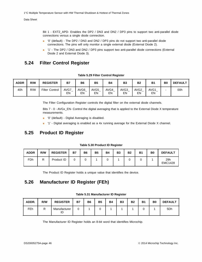
1°C Multiple Temperature Sensor with HW Thermal Shutdown & Hottest of Thermal Zones
Data Sheet
ADD LT
40
Bit 1 - EXT2_APD- Enables the DP2 / DN3 and DN2 / DP3 pins to support two anti-parallel diodeconnections versus a single diode connection.
‘0’ (default) - The DP2 / DN3 and DN2 / DP3 pins do not support two anti-parallel diode connections. The pins will only monitor a single external diode (External Diode 2).
‘1’ - The DP2 / DN3 and DN2 / DP3 pins support two anti-parallel diode connections (External Diode 2 and External Diode 3).
5.24 Filter Control Register
The Filter Configuration Register controls the digital filter on the external diode channels.
Bits 7 - 0 - AVGx_EN- Control the digital averaging that is applied to the External Diode X temperaturemeasurements.
‘0’ (default) - Digital Averaging is disabled.
‘1’ - Digital averaging is enabled as a 4x running average for the External Diode X channel.
5.25 Product ID Register
The Product ID Register holds a unique value that identifies the device.
5.26 Manufacturer ID Register (FEh)
The Manufacturer ID Register holds an 8-bit word that identifies Microchip.
Table 5.29 Filter Control Register
R R/W REGISTER B7 B6 B5 B4 B3 B2 B1 B0 DEFAU
h R/W Filter Control AVG7_EN
AVG6_EN
AVG5_EN
AVG4_EN
AVG3_EN
AVG2_EN
AVG1_EN
- 00h
Table 5.30 Product ID Register
ADDR R/W REGISTER B7 B6 B5 B4 B3 B2 B1 B0 DEFAULT
FDh R Product ID 0 0 1 0 1 0 0 1 29hEMC1428
Table 5.31 Manufacturer ID Register
ADDR. R/W REGISTER B7 B6 B5 B4 B3 B2 B1 B0 DEFAULT
FEh R Manufacturer ID
0 1 0 1 1 1 0 1 5Dh
DS20005275A-page 46 2014 Microchip Technology Inc.

1°C Multiple Temperature Sensor with HW Thermal Shutdown & Hottest of Thermal Zones
Data Sheet
5.27 Revision Register (FFh)
The Revision register contains an 8 bit word that identifies the die revision.
Table 5.32 Revision Register
ADDR. R/W REGISTER B7 B6 B5 B4 B3 B2 B1 B0 DEFAULT
FFh R Revision 0 0 0 0 0 0 0 1 01h
2014 Microchip Technology Inc. DS20005275A-page 47

1°C Multiple Temperature Sensor with HW Thermal Shutdown & Hottest of Thermal Zones
Data Sheet
Chapter 6 Package Information
Note: For the most current package drawings, see the Microchip Packaging Specification athttp://www.microchip.com/packaging.
6.1 EMC1428 Package Drawing
Figure 6.1 16-Pin QFN 4mm x 4mm Package Dimensions
DS20005275A-page 48 2014 Microchip Technology Inc.

1°C Multiple Temperature Sensor with HW Thermal Shutdown & Hottest of Thermal Zones
Data Sheet
Figure 6.2 16-Pin QFN 4mm x 4mm Package Drawing
2014 Microchip Technology Inc. DS20005275A-page 49

1°C Multiple Temperature Sensor with HW Thermal Shutdown & Hottest of Thermal Zones
Data Sheet
6.2 Package Markings
6.2.1 EMC1428-X-AP (16-Pin QFN)All devices will be marked on the first line of the top side with “1428” and “-X”. On they second line,packages are marked with the Lot Number. On the third line, packages are marked with FunctionalRevision code “B” and the Country Code (CC).
Figure 6.3 16-Pin QFN 4mm x 4mm PCB Footprint
DS20005275A-page 50 2014 Microchip Technology Inc.

1°C Multiple Temperature Sensor with HW Thermal Shutdown & Hottest of Thermal Zones
Data Sheet
2014 Microchip Technology Inc. DS20005275A-page 51
Chapter 7 Data Sheet Revision History
Table 7.1 Revision History
REVISION LEVEL AND DATE SECTION/FIGURE/ENTRY CORRECTION
REV A REV A replaces previous SMSC version Rev. 0.70 (04-19-13)
Rev. 0.70 (04-19-13) Ordering Number Corrected EMC1428-7 part number, adding -CB7 as a suffix
Rev. 0.69 (06-29-09) Table 1.1, "EMC1428 Pin Description" Added “requires external pullup resistor” to SMDATA and SMCLK in function column
Table 1.1, "EMC1428 Pin Description" Added the following application note below table: “For the 5V tolerant pins that have a pull-up resistor, the voltage difference between VDD and the pull-up voltage must never exceed 3.6V.”
Table 2.1, "Absolute Maximum Ratings"
Updated voltage limits for 5V tolerant pins with pull-up resistors.
Added the following note below table: “For the 5V tolerant pins that have a pull-up resistor, the pull-up voltage must not exceed 3.6V when the device is unpowered.”
Updated thetaJA from 40 to 50.
Rev. 0.67 (06-16-08) Ordering Information Added EMC1428-7
Section 3.7, "SMBus Address" Added EMC1428-7 Address options
1°C Multiple Temperature Sensor with Beta Compensation and Hottest of Multiple Zones
Data Sheet
DS20005275A-page 52 2014 Microchip Technology Inc.
Note the following details of the code protection feature on Microchip devices:• Microchip products meet the specification contained in their particular Microchip Data Sheet.
• Microchip believes that its family of products is one of the most secure families of its kind on the market today, when used in the intended manner and under normal conditions.
• There are dishonest and possibly illegal methods used to breach the code protection feature. All of these methods, to our knowledge, require using the Microchip products in a manner outside the operating specifications contained in Microchip’s Data Sheets. Most likely, the person doing so is engaged in theft of intellectual property.
• Microchip is willing to work with the customer who is concerned about the integrity of their code.
• Neither Microchip nor any other semiconductor manufacturer can guarantee the security of their code. Code protection does not mean that we are guaranteeing the product as “unbreakable.”
Code protection is constantly evolving. We at Microchip are committed to continuously improving the code protection features of ourproducts. Attempts to break Microchip’s code protection feature may be a violation of the Digital Millennium Copyright Act. If such actsallow unauthorized access to your software or other copyrighted work, you may have a right to sue for relief under that Act.
Information contained in this publication regarding device applications and the like is provided only for your convenience and may besuperseded by updates. It is your responsibility to ensure that your application meets with your specifications. MICROCHIP MAKES NOREPRESENTATIONS OR WARRANTIES OF ANY KIND WHETHER EXPRESS OR IMPLIED, WRITTEN OR ORAL, STATUTORY OROTHERWISE, RELATED TO THE INFORMATION, INCLUDING BUT NOT LIMITED TO ITS CONDITION, QUALITY, PERFORMANCE,MERCHANTABILITY OR FITNESS FOR PURPOSE. Microchip disclaims all liability arising from this information and its use. Use ofMicrochip devices in life support and/or safety applications is entirely at the buyer’s risk, and the buyer agrees to defend, indemnify andhold harmless Microchip from any and all damages, claims, suits, or expenses resulting from such use. No licenses are conveyed, implic-itly or otherwise, under any Microchip intellectual property rights.
Trademarks
The Microchip name and logo, the Microchip logo, dsPIC, FlashFlex, KEELOQ, KEELOQ logo, MPLAB, PIC, PICmicro, PICSTART, PIC32 logo, rfPIC, SST, SST Logo, SuperFlash and UNI/O are registered trademarks of Microchip Technology Incorporated in the U.S.A. and other countries.
FilterLab, Hampshire, HI-TECH C, Linear Active Thermistor, MTP, SEEVAL and The Embedded Control Solutions Company are registered trademarks of Microchip Technology Incorporated in the U.S.A.
Silicon Storage Technology is a registered trademark of Microchip Technology Inc. in other countries.
Analog-for-the-Digital Age, Application Maestro, BodyCom, chipKIT, chipKIT logo, CodeGuard, dsPICDEM, dsPICDEM.net, dsPICworks, dsSPEAK, ECAN, ECONOMONITOR, FanSense, HI-TIDE, In-Circuit Serial Programming, ICSP, Mindi, MiWi, MPASM, MPF, MPLAB Certified logo, MPLIB, MPLINK, mTouch, Omniscient Code Generation, PICC, PICC-18, PICDEM, PICDEM.net, PICkit, PICtail, REAL ICE, rfLAB, Select Mode, SQI, Serial Quad I/O, Total Endurance, TSHARC, UniWinDriver, WiperLock, ZENA and Z-Scale are trademarks of Microchip Technology Incorporated in the U.S.A. and other countries.
SQTP is a service mark of Microchip Technology Incorporated in the U.S.A.
GestIC and ULPP are registered trademarks of Microchip Technology Germany II GmbH & Co. KG, a subsidiary of Microchip Technology Inc., in other countries.
A more complete list of registered trademarks and common law trademarks owned by Standard Microsystems Corporation (“SMSC”) is available at: www.smsc.com. The absence of a trademark (name, logo, etc.) from the list does not constitute a waiver of any intellectual property rights that SMSC has established in any of its trademarks.
All other trademarks mentioned herein are property of their respective companies.
© 2014, Microchip Technology Incorporated, Printed in the U.S.A., All Rights Reserved.
ISBN: 9781620779552
Microchip received ISO/TS-16949:2009 certification for its worldwide headquarters, design and wafer fabrication facilities in Chandler and Tempe, Arizona; Gresham, Oregon and design centers in California and India. The Company’s quality system processes and procedures are for its PIC® MCUs and dsPIC® DSCs, KEELOQ® code hopping devices, Serial EEPROMs, microperipherals, nonvolatile memory and analog products. In addition, Microchip’s quality system for the design and manufacture of development systems is ISO 9001:2000 certified.

DS20005275A-page 53 2014 Microchip Technology Inc.
AMERICASCorporate Office2355 West Chandler Blvd.Chandler, AZ 85224-6199Tel: 480-792-7200 Fax: 480-792-7277Technical Support: http://www.microchip.com/supportWeb Address: www.microchip.comAtlantaDuluth, GA Tel: 678-957-9614 Fax: 678-957-1455Austin, TXTel: 512-257-3370 BostonWestborough, MA Tel: 774-760-0087 Fax: 774-760-0088ChicagoItasca, IL Tel: 630-285-0071 Fax: 630-285-0075ClevelandIndependence, OH Tel: 216-447-0464 Fax: 216-447-0643DallasAddison, TX Tel: 972-818-7423 Fax: 972-818-2924DetroitNovi, MI Tel: 248-848-4000Houston, TX Tel: 281-894-5983IndianapolisNoblesville, IN Tel: 317-773-8323Fax: 317-773-5453Los AngelesMission Viejo, CA Tel: 949-462-9523 Fax: 949-462-9608New York, NY Tel: 631-435-6000San Jose, CA Tel: 408-735-9110Canada - TorontoTel: 905-673-0699 Fax: 905-673-6509
ASIA/PACIFICAsia Pacific OfficeSuites 3707-14, 37th FloorTower 6, The GatewayHarbour City, KowloonHong KongTel: 852-2401-1200Fax: 852-2401-3431Australia - SydneyTel: 61-2-9868-6733Fax: 61-2-9868-6755China - BeijingTel: 86-10-8569-7000 Fax: 86-10-8528-2104China - ChengduTel: 86-28-8665-5511Fax: 86-28-8665-7889China - ChongqingTel: 86-23-8980-9588Fax: 86-23-8980-9500China - HangzhouTel: 86-571-2819-3187 Fax: 86-571-2819-3189China - Hong Kong SARTel: 852-2943-5100 Fax: 852-2401-3431China - NanjingTel: 86-25-8473-2460Fax: 86-25-8473-2470China - QingdaoTel: 86-532-8502-7355Fax: 86-532-8502-7205China - ShanghaiTel: 86-21-5407-5533 Fax: 86-21-5407-5066China - ShenyangTel: 86-24-2334-2829Fax: 86-24-2334-2393China - ShenzhenTel: 86-755-8864-2200 Fax: 86-755-8203-1760China - WuhanTel: 86-27-5980-5300Fax: 86-27-5980-5118China - XianTel: 86-29-8833-7252Fax: 86-29-8833-7256China - XiamenTel: 86-592-2388138 Fax: 86-592-2388130China - ZhuhaiTel: 86-756-3210040 Fax: 86-756-3210049
ASIA/PACIFICIndia - BangaloreTel: 91-80-3090-4444 Fax: 91-80-3090-4123India - New DelhiTel: 91-11-4160-8631Fax: 91-11-4160-8632India - PuneTel: 91-20-3019-1500Japan - OsakaTel: 81-6-6152-7160 Fax: 81-6-6152-9310Japan - TokyoTel: 81-3-6880- 3770 Fax: 81-3-6880-3771Korea - DaeguTel: 82-53-744-4301Fax: 82-53-744-4302Korea - SeoulTel: 82-2-554-7200Fax: 82-2-558-5932 or 82-2-558-5934Malaysia - Kuala LumpurTel: 60-3-6201-9857Fax: 60-3-6201-9859Malaysia - PenangTel: 60-4-227-8870Fax: 60-4-227-4068Philippines - ManilaTel: 63-2-634-9065Fax: 63-2-634-9069SingaporeTel: 65-6334-8870Fax: 65-6334-8850Taiwan - Hsin ChuTel: 886-3-5778-366Fax: 886-3-5770-955Taiwan - KaohsiungTel: 886-7-213-7830Taiwan - TaipeiTel: 886-2-2508-8600 Fax: 886-2-2508-0102Thailand - BangkokTel: 66-2-694-1351Fax: 66-2-694-1350
EUROPEAustria - WelsTel: 43-7242-2244-39Fax: 43-7242-2244-393Denmark - CopenhagenTel: 45-4450-2828 Fax: 45-4485-2829France - ParisTel: 33-1-69-53-63-20 Fax: 33-1-69-30-90-79Germany - DusseldorfTel: 49-2129-3766400Germany - MunichTel: 49-89-627-144-0 Fax: 49-89-627-144-44Germany - PforzheimTel: 49-7231-424750Italy - Milan Tel: 39-0331-742611 Fax: 39-0331-466781Italy - VeniceTel: 39-049-7625286 Netherlands - DrunenTel: 31-416-690399 Fax: 31-416-690340Poland - WarsawTel: 48-22-3325737 Spain - MadridTel: 34-91-708-08-90Fax: 34-91-708-08-91Sweden - StockholmTel: 46-8-5090-4654UK - WokinghamTel: 44-118-921-5800Fax: 44-118-921-5820
Worldwide Sales and Service
10/28/13