EMC Symmetrix DMX-4 Product Guide Symmetrix DMX-4 Product Guide 3 Warnings and Cautions 17 Preface...
330
EMC Corporation Corporate Headquarters: Hopkinton, MA 01748-9103 1-508-435-1000 www.EMC.com EMC ® Symmetrix ® DMX-4 Product Guide P/N 300-004-996 REV A05
Transcript of EMC Symmetrix DMX-4 Product Guide Symmetrix DMX-4 Product Guide 3 Warnings and Cautions 17 Preface...
EMC® Symmetrix®
DMX-4
Product GuideP/N 300-004-996
REV A05
EMC CorporationCorporate Headquarters:
Hopkinton, MA 01748-9103
1-508-435-1000www.EMC.com
2
EMC Symmetrix DMX-4 Product GuideCopyright © 2005-2008 EMC Corporation. All rights reserved.
Published December, 2008
EMC believes the information in this publication is accurate as of its publication date. The information is subject to change without notice.
THE INFORMATION IN THIS PUBLICATION IS PROVIDED “AS IS.” EMC CORPORATION MAKES NO REPRESENTATIONS OR WARRANTIES OF ANY KIND WITH RESPECT TO THE INFORMATION IN THIS PUBLICATION, AND SPECIFICALLY DISCLAIMS IMPLIED WARRANTIES OF MERCHANTABILITY OR FITNESS FOR A PARTICULAR PURPOSE.
Use, copying, and distribution of any EMC software described in this publication requires an applicable software license.
For the most up-to-date regulatory document for your product line, go to the Technical Documentation and Advisories section on EMC Powerlink.
For the most up-to-date listing of EMC product names, see EMC Corporation Trademarks on EMC.com.
All other trademarks used herein are the property of their respective owners.

Contents
Warnings and Cautions......................................................................... 17
Preface ................................................................................................... 21
Chapter 1 Introducing the Symmetrix DMX-4Symmetrix DMX-4 ............................................................................ 26
Symmetrix DMX-4 configurations .......................................... 27Symmetrix platform and Enginuity operating environment ..... 29
Enginuity operating environment........................................... 29EMC Solutions Enabler APIs ................................................... 30
Storage capacities and global memory requirements.................. 31Storage capacities....................................................................... 31Factors affecting storage capacity............................................ 31Global memory requirements .................................................. 32
Performance features........................................................................ 33Availability and integrity features.................................................. 35Serviceability features ...................................................................... 37Supported software .......................................................................... 38
Tiered storage optimization ..................................................... 38Storage management................................................................. 39Symmetrix local and remote replication software solutions 39Information mobility ................................................................. 40
Hardware options ............................................................................. 41DMX-4 Silencer .......................................................................... 41DMX-4 Silencer specifications ................................................. 42DMX-4 systems securing kits................................................... 43
EMC Symmetrix DMX-4 Product Guide 3
Contents
Chapter 2 Symmetrix DMX-4 HardwareMajor components ............................................................................ 46
Symmetrix DMX-4 and component scaling attributes......... 50DMX-4 configuration rules and guidelines ........................... 51
Symmetrix DMX-4 architecture ...................................................... 53DMX-4 block diagram............................................................... 53DMX-4 point-to-point message matrix................................... 55DMX-4 midplane slot configuration....................................... 56DMX-4 slot configuration......................................................... 56
Symmetrix channel connectivity and host integration ............... 59Channel connectivity ................................................................ 59Symmetrix channel configurations ......................................... 60Supported Fibre Channel interfaces ....................................... 60Supported cluster hosts ............................................................ 60Mainframe serial channel interfaces ....................................... 60Supported mainframe operating systems.............................. 61
Fibre Channel disk subsystem ........................................................ 62Disk drives.................................................................................. 62SATA II drives ............................................................................ 63Flash drives ................................................................................ 64Link control cards...................................................................... 65Power supply/cooling module ............................................... 66Symmetrix DMX disk drive capacities ................................... 66Symmetrix DMX-4 logical volume capacities ....................... 68Configuration rules for vault devices..................................... 70Symmetrix DMX disk drive emulations ................................ 70Deleting (and then adding) devices online............................ 71Open system disk emulation ................................................... 71IBM CKD DASD disk emulation............................................. 73
Channel, disk, and global memory directors ............................... 76Channel director connectivity ................................................. 76Channel director descriptions.................................................. 77Fibre Channel directors front-end........................................... 78Fibre Channel adapters front-end ........................................... 79ESCON channel directors......................................................... 80Multiprotocol Channel Directors ............................................ 81FICON channel director ........................................................... 81Gigabit Ethernet (GigE) remote directors .............................. 82GigE IPv4/v6 (IPsec capable) channel director .............................................. 83iSCSI channel directors ............................................................. 83Fibre Channel disk directors back-end................................... 84Global memory directors.......................................................... 84
EMC Symmetrix DMX-4 Product Guide4

Contents
Global memory director configuration................................... 86Symmetrix DMX-4 power subsystems........................................... 87
System bay power subsystem components ........................... 87Storage bay power subsystem components ........................... 88
DMX-4 communications and environmental control .................. 90Communications control functions ......................................... 90Environmental control functions ............................................. 91
Channel attachments ........................................................................ 93FICON channel interface connections .................................... 93ESCON channel interface connections ................................... 96Mainframe serial channel extenders ....................................... 98Open systems Fibre Channel interface connections ............. 99
Chapter 3 Symmetrix DMX-4 Input/Output OperationsSymmetrix DMX-4 operation ........................................................ 102
Symmetrix global memory management ............................. 103Elements of a Symmetrix I/O operation ..................................... 105
I/O response time: Mainframe environment....................... 105I/O response time: Open systems environment ................. 106Symmetrix I/O operations ..................................................... 106Read operations........................................................................ 108Write operations ....................................................................... 110Write destaging operation ...................................................... 112
I/O performance enhancements................................................... 113
Chapter 4 Performance and OptimizationOverview .......................................................................................... 116Global memory performance features ......................................... 117
Global memory ASICs............................................................. 118Tag Based Caching (TBC)........................................................ 119Fast write capabilities .............................................................. 120Dynamic Mirror Service Policy (DMSP) algorithm ............ 120Disk Rotational Position Ordering (RPO) ............................ 120Disk Multiple Priority Queues (DMPQ)............................... 120PermaCache option.................................................................. 121
Symmetrix file system performance features.............................. 122Dynamically adjusting performance algorithms................. 122Enhancement of dynamic mirror service policy ................. 122Enhancement of Symmetrix Optimizer ................................ 122Enhanced system audit and investigation ........................... 123
Multiple channel directors ............................................................. 124
5EMC Symmetrix DMX-4 Product Guide

Contents
Channel speeds and cable lengths ........................................ 124Host connectivity..................................................................... 126
Open systems hypervolumes ....................................................... 127Hypervolume extension feature............................................ 127Disk drive cylinders ................................................................ 127Logical volume mapping ....................................................... 128Metavolumes............................................................................ 129
Mainframe systems hypervolumes ............................................. 132Hypervolume extension options........................................... 132Split-volume capability........................................................... 132Extended cylinder addressing option................................... 133Determining cylinders for hypervolume user data............ 134
Tiered storage optimization .......................................................... 136Symmetrix Priority Controls.................................................. 136Dynamic Cache Partitioning.................................................. 137
Optimizing Symmetrix system performance ............................. 139Performance guidelines for open system devices............... 139Virtual LUN technology ......................................................... 140Virtual LUN management...................................................... 140
Dynamic Host Addressing ............................................................ 145Virtual Provisioning ....................................................................... 146
Virtual Provisioning description ........................................... 146Benefits of Virtual Provisioning ............................................ 147Virtual Provisioning features ................................................. 147
Multiport volume access for open systems environments ....... 149Software options overview............................................................ 150
EMC ControlCenter family of products............................... 150Symmetrix Optimizer ............................................................. 153TimeFinder family of products.............................................. 154Solutions Enabler..................................................................... 155Symmetrix Management Console ......................................... 155
Chapter 5 Data Integrity, Availability, and ProtectionOverview.......................................................................................... 158
Symmetrix reliability and availability features................... 158Symmetrix data integrity protection features ..................... 158Data protection options .......................................................... 159
Reliability and availability features ............................................. 162Reliable components ............................................................... 162Global memory director data integrity ................................ 162Redundant global memory .................................................... 162Channel director redundancy................................................ 163
EMC Symmetrix DMX-4 Product Guide6

Contents
Internal control data path redundancy................................. 164Fibre Channel back-end redundancy.................................... 164Fibre Channel arbitrated loop design ................................... 165Dual-initiator feature .............................................................. 168Redundant power subsystem ................................................ 169Vaulting ..................................................................................... 169Power loss to one power zone................................................ 170Battery backup units (BBU) .................................................... 171Nondisruptive component replacement............................... 172Nondisruptive Enginuity upgrades ...................................... 173Nondisruptively change or remove drives .......................... 174Deleting (and then adding) devices online .......................... 174
Maintaining data integrity ............................................................ 175Remote support ........................................................................ 175Error Checking and Correction, and data integrityprotection .................................................................................. 176Disk error correction and error verification ......................... 177Global memory director data integrity logic ....................... 178Global memory error correction and error verification...... 178Global memory chip-level redundancy................................ 179Redundant global memory..................................................... 179Longitude redundancy code (LRC)....................................... 179Byte-level parity checking ...................................................... 179Global memory access path protection................................. 180
DMX-4 security features................................................................. 181Security overview .................................................................... 182Symmetrix Service Credential, Secured by RSA ................. 182Access control and user authorization.................................. 183Symmetrix Audit Log.............................................................. 185RSA enVision log security ...................................................... 185EMC Certified Data Erasure for Symmetrix Disks ............. 186IPsec security features ............................................................. 187
Data protection guidelines............................................................. 189Disk mirroring (RAID 1) concepts ................................................ 191
Advantages of mirroring ........................................................ 191Write operations with mirroring............................................ 191Read operations with mirroring ............................................ 192Error recovery with mirroring ............................................... 192Dynamic Mirror Service Policy (DMSP)............................... 193Business Continuance Volumes (BCV) ................................. 193Virtual devices .......................................................................... 194
Symmetrix RAID 1/0 for open systems....................................... 195Symmetrix RAID 10 for mainframe systems .............................. 196
7EMC Symmetrix DMX-4 Product Guide
Contents
Symmetrix DMX RAID 5 ............................................................... 198RAID 5 overview ..................................................................... 198RAID 5 attributes..................................................................... 198RAID 5 device (volume) ......................................................... 198RAID 5 (3+1)............................................................................. 199RAID 5 (7+1)............................................................................. 199RAID 5 modes of operation ................................................... 199Normal mode ........................................................................... 200Regeneration ............................................................................ 202RAID 5 performance optimization ....................................... 204RAID 5 configuration guidelines .......................................... 205RAID 5 configuration rules .................................................... 205
Symmetrix DMX RAID 6 ............................................................... 206RAID 6 overview ..................................................................... 206RAID 6 attributes..................................................................... 206RAID 6 device (volume) ......................................................... 206Even-Odd algorithm ............................................................... 207RAID 6 (6+2)............................................................................. 208RAID 6 (14+2)........................................................................... 208Rebuilding data and parity members................................... 209RAID 6 configuration guidelines .......................................... 210Comparing RAID 5 and RAID 6 ........................................... 210
Sparing in Symmetrix systems ..................................................... 211Sparing configuration rules and guidelines ........................ 211Flash drive sparing rules ........................................................ 211Sparing benefits ....................................................................... 212Permanent sparing .................................................................. 212Dynamic sparing ..................................................................... 215
SRDF family of products ............................................................... 219Base SRDF family products.................................................... 219SRDF family options ............................................................... 220SRDF/A resiliency features ................................................... 220
Chapter 6 Mainframe Features and SupportIntroduction..................................................................................... 224Supported mainframe features ..................................................... 225
EMC z/OS Storage Manager ................................................. 225Dynamic Channel Management............................................ 226Dynamic Path Reconnection ................................................. 226Concurrent Copy ..................................................................... 226Compatible Native Flash for Mainframe ............................. 227Multi-Path Lock Facility/Concurrent Access...................... 228
EMC Symmetrix DMX-4 Product Guide8

Contents
MultiSubsystem Imaging........................................................ 228Sequential Data Striping ......................................................... 228Partitioned Data Set (PDS) Assist ......................................... 229Multiple Allegiance (MA)....................................................... 229Parallel Access Volumes.......................................................... 229Compatible HyperPAV............................................................ 229Dynamic Parallel Access Volumes......................................... 230RAID 10 striping ...................................................................... 231Supported ESCON devices and logical paths...................... 231Supported FICON devices and logical paths .......................232IBM MetroMirror (PPRC) ....................................................... 233XRC support ............................................................................. 234Configuring CKD volumes..................................................... 235Deleting (and then adding) devices online .......................... 235Support for 64 K cylinders...................................................... 236FICON Cascading and Open Systems Intermixconfigurations........................................................................... 236
Error reporting and recovery......................................................... 238Types of errors .......................................................................... 238Error reporting.......................................................................... 240Operator messages................................................................... 244EREP reports ............................................................................. 246Error handling .......................................................................... 247Detecting the error ................................................................... 248
Sense byte information ................................................................... 249Console error messages........................................................... 249Host sense byte data formats ................................................. 251
Appendix A Symmetrix DMX-4 SpecificationsStorage control ................................................................................. 254Physical data .................................................................................... 263Environmental data ........................................................................ 265Power and cooling data.................................................................. 269Electrical specifications and power requirements...................... 270
North American power specifications .................................. 271North American extension cords and mating connectors.................................................................... 271International power specifications ........................................ 275International extension cordsand mating connectors ............................................................ 275
9EMC Symmetrix DMX-4 Product Guide

Contents
Appendix B Power SequencesVaulting ............................................................................................ 280Routinely powering up the Symmetrix DMX-4 ......................... 281Powering down the Symmetrix DMX-4...................................... 283
Appendix C Planning and InstallationPlanning overview.......................................................................... 286
Symmetrix DMX-4 presite considerations ........................... 286Layout and space recommendations .................................... 288Securing the system................................................................. 288Transportation and delivery guidelines ............................... 289Remote support ....................................................................... 289Planning for upgrades ............................................................ 289
Symmetrix DMX-4 power requirements ..................................... 290Regulatory compliance ........................................................... 293Choosing a UPS ....................................................................... 294
System placement options............................................................. 295Overhead host cable routing.................................................. 296Overhead power cable routing.............................................. 296Floor load-bearing requirements........................................... 297Symmetrix DMX-4 configuration floor cutouts .................. 299
Planning host connectivity ............................................................ 300Open systems installations............................................................ 304
Symmetrix hardware checklist .............................................. 304Host checklist ........................................................................... 305Available EMC Fibre Channel cables.................................... 307Available EMC GigE/iSCSI cables........................................ 308
Mainframe systems installations .................................................. 309Symmetrix hardware checklist .............................................. 309Available EMC ESCON cables .............................................. 310Available EMC FICON cables ............................................... 311
Glossary ............................................................................................... 313
Index .................................................................................................... 325
EMC Symmetrix DMX-4 Product Guide10

Title Page
Figures
1 Symmetrix DMX-4 nine-bay configuration ................................................ 272 Symmetrix DMX-4 five-bay configuration ................................................. 283 Symmetrix DMX-4 two-bay configuration ................................................. 284 Enginuity and the storage platform relationships ..................................... 295 DMX-4 Silencer ............................................................................................... 416 Symmetrix DMX-4 system bay (interior view, front and rear) ................ 477 Symmetrix DMX-4 storage bay (interior view, front and rear) ............... 498 Symmetrix DMX-4 block diagram ............................................................... 549 Symmetrix DMX-4 message fabric .............................................................. 5510 Card cage configurations front ..................................................................... 5711 Symmetrix DMX-4 card cage configurations (rear) .................................. 5812 Track format for 3390 DASD ........................................................................ 7413 Global memory director to channel and disk director matrix ................. 8514 Symmetrix DMX-4 system bay and storage bay to
customer PDU power cabling ...................................................................... 8915 Communication to directors ......................................................................... 9116 XCM environmental control functionality ................................................. 9217 FICON channel attachments ......................................................................... 9418 ESCON channel attachments ........................................................................ 9719 Host cache use .............................................................................................. 10220 Symmetrix global memory management and data flow ........................ 10321 I/O response time (mainframe environment) ......................................... 10522 I/O response time (open systems environment) ..................................... 10623 Symmetrix I/O operations .......................................................................... 10724 Read operations ............................................................................................ 10825 Read hit .......................................................................................................... 10826 Read miss ....................................................................................................... 10927 Write operations ........................................................................................... 11028 Fast write ....................................................................................................... 11129 Delayed fast write ........................................................................................ 111
EMC Symmetrix DMX-4 Product Guide 11

Figures
Title Page
30 Destaging operation ..................................................................................... 11231 TBC LRU function ........................................................................................ 11932 Logical volume mapping (8:1) ................................................................... 12833 Concatenated volumes ................................................................................ 13034 Striped data ................................................................................................... 13035 SMC migration dialog box step 1 .............................................................. 14236 SMC migration dialog box step 2 .............................................................. 14337 SMC migration dialog box step 3 .............................................................. 14438 Fibre Channel back-end redundancy ........................................................ 16739 Symmetrix DMX dual-initiator example .................................................. 16940 Data record format for conventional DASD ............................................ 17641 Symmetrix data record format ................................................................... 17742 RAID 10 with Dynamic Mirror Service Policy ......................................... 19643 RAID 5 data/parity (3+1) ........................................................................... 19944 Writing data in RAID 5 normal mode ...................................................... 20145 Reading data in RAID 5 normal mode ..................................................... 20246 RAID 6 (6+2) data/parity layout ............................................................... 20847 RAID 6 (14+2) ............................................................................................... 20948 Permanent sparing process ......................................................................... 21449 Dynamic sparing process ............................................................................ 21550 Dynamic sparing with locally mirrored pairs ......................................... 21751 Dynamic support of Parallel Access Volumes ......................................... 23152 Supported ESCON logical paths per port ................................................ 23253 Supported FICON logical paths per port ................................................. 23254 PPRC and GDPS support ............................................................................ 23355 XRC overview ............................................................................................... 23556 z/OS IEA480E service alert error message format
(AC power failure) ....................................................................................... 24457 z/OS IEA480E service alert error message format
(mirror-1 volume in “not ready” state) ..................................................... 24558 z/OS IEA480E service alert error message format
(mirror-2 resynchronization) ...................................................................... 24559 z/OS IEA480E service alert error message format
(mirror-1 resynchronization) ...................................................................... 24660 Typical console error message ................................................................... 24961 Power connections ....................................................................................... 27062 EMC model number DMX4-PCBL3DHR cable description .................. 272
EMC Symmetrix DMX-4 Product Guide12

Figures
Title Page
63 EMC model number DMX4-PCBL3DHH cable description .................. 27364 System bay and storage bay wiring, North America (Delta) ................. 27465 EMC model number DMX4-PC3YAFLE cable description .................... 27666 EMC model number DMX4-PCBL3YAG cable description ................... 27667 System bay and storage bay wiring with flying leads (WYE) ............... 27768 Symmetrix DMX-4 system bay and storage bay power switches ......... 28269 DMX-4 system bay and storage bay to customer
PDU power cabling ...................................................................................... 29070 DMX-4 power cabling requirement ........................................................... 29171 Nonraised floor installation ........................................................................ 29572 One system bay and eight storage bays .................................................... 299
13EMC Symmetrix DMX-4 Product Guide

Figures
EMC Symmetrix DMX-4 Product Guide14
Title Page
Tables
1 Symmetrix DMX-4 performance features.....................................................262 Performance features roadmap......................................................................333 Availability and integrity features roadmap................................................354 DMX-4 Silencer kits model information .......................................................425 DMX-4 Silencer physical specifications ........................................................426 Symmetrix DMX-4 model component overview.........................................467 Symmetrix DMX-4 system bay component overview ................................488 Symmetrix DMX-4 storage bay component overview................................509 DMX-4 configurations .....................................................................................5110 IBM controller/DASD compatibility.............................................................6111 Symmetrix DMX-4 disk drive features ........................................................6312 Symmetrix DMX-4 disk drive capacities ......................................................6713 Logical volumes supported on Symmetrix DMX-4 drives ........................6814 Logical volumes supported for DMX-4 systems .........................................6915 IBM DASD emulation characteristics............................................................7416 Supported protocols and Symmetrix DMX-4 channel directors ...............7717 Symmetrix DMX-4 channel director models and descriptions .................7818 Symmetrix devices and addressing capabilities
for Fibre Channel front-end directors ...........................................................7919 ESCON director configurations .....................................................................8020 FICON director configurations ......................................................................8221 Symmetrix FICON cable distances ...............................................................9422 Symmetrix ESCON cable distances ...............................................................9823 Symmetrix Fibre Channel cable distances ...................................................9924 Symmetrix open systems disk capacities and cylinders...........................12825 Symmetrix mainframe disk capacities and cylinders ...............................13426 Device emulations and number of cylinders .............................................13527 Symmetrix DMX-4 channel director connectivity .....................................16328 Data protection options .................................................................................19029 RAID 5 write operation sequence in normal mode...................................20030 RAID 5 and RAID 6 comparison..................................................................210
EMC Symmetrix DMX-4 Product Guide 15

Tables
Title Page
31 Environmental errors reported as SIM messages...................................... 24232 Error handling steps ...................................................................................... 24733 Unit status bits ................................................................................................ 25034 Channel status bits......................................................................................... 25035 DMX-4 73 GB disk capacities ....................................................................... 25536 DMX-4 146 GB disk capacities ..................................................................... 25637 DMX-4 300 GB disk capacities ..................................................................... 25738 DMX-4 400 GB disk capacities ..................................................................... 25839 DMX-4 450 GB disk capacities ..................................................................... 25940 DMX-4 500 GB disk capacities ..................................................................... 26041 DMX-4 1 TB disk capacities .......................................................................... 26142 Physical specifications................................................................................... 26343 Multibay width measurements ................................................................... 26344 Multibay weights ........................................................................................... 26445 Data center acclimation times ...................................................................... 26646 System environment data ............................................................................. 26647 Shipping and storage environment specifications .................................... 26748 Air volume generated.................................................................................... 26749 Sound power and sound pressure levels.................................................... 26850 DMX-4 power consumption and heat dissipation .................................... 26951 Electrical specifications, North American, three-phase, four-wire
(Delta) .............................................................................................................. 27152 Extension line cord, North American, three-phase, four-wire (Delta)... 27253 Electrical specifications, international, three-phase, five-wire (WYE) ... 27554 Extension line cord, international, three-phase, five-wire (WYE) .......... 27555 Preinstallation responsibility summary...................................................... 28656 Symmetrix DMX-4 channel adapter port worksheet................................ 30257 Symmetrix checklist for UNIX or PC server hosts .................................... 30458 UNIX or PC server host checklist ................................................................ 30559 EMC Fibre cables—Fibre Channel connect ................................................ 30760 GigE/iSCSI channel cables ........................................................................... 30861 Symmetrix checklist for mainframe hosts .................................................. 30962 ESCON channel cables .................................................................................. 31063 EMC Fibre cables—FICON 9 micron connect............................................ 311
EMC Symmetrix DMX-4 Product Guide16

The following warnings and cautions pertain throughout this guide:
WARNING Trained service personnel only.
This EMC product has more than one power supply cord. To reduce the risk of electric shock, disconnect all power supply cords before servicing.
Ground circuit continuity is vital for safe operation of the machine. Never operate the machine with grounding conductors disconnected. Remember to reconnect any grounding conductors removed for or during any installation procedure.
ATTENTION Resérvé au personnel autorisé.
Cet appareil EMC comporte plus d'un cordon d'alimentation. Afin de prévenir les chocs électriques, débranchez tous les cordons d'alimentation avant de faire le dépannage.
Un circuit de terre continu est essentiel en vue du fonctionnement sécurisé de l'appareil. Ne mettez jamais l'appareil en marche lorsque le conducteur de mise à la terre est débranché.
WARNUNG Nur für authorisiertes Fachpersonal.
Dieses EMC Produkt verfügt über mehrere elektrische Netzanschlüsse. Zur Vermeidung eines elektrischen Schlages sind vor Servicearbeiten an der Stromversorgung alle Netzanschlüsse zu trennen.
Warnings andCautions
EMC Symmetrix DMX-4 Product Guide 17
18
Warnings and Cautions
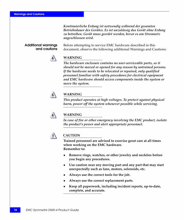
Kontinuierliche Erdung ist notwendig während der gesamten Betriebsdauer des Gerätes. Es ist unzulässig das Gerät ohne Erdung zu betreiben. Gerät muss geerdet werden, bevor es am Stromnetz angeschlossen wird.
Additional warningsand cautions
Before attempting to service EMC hardware described in this document, observe the following additional Warnings and Cautions:
WARNING
The hardware enclosure contains no user-serviceable parts, so it should not be moved or opened for any reason by untrained persons. If the hardware needs to be relocated or repaired, only qualified personnel familiar with safety procedures for electrical equipment and EMC hardware should access components inside the system or move the system.
WARNING
This product operates at high voltages. To protect against physical harm, power off the system whenever possible while servicing.
WARNING
In case of fire or other emergency involving the EMC product, isolate the product’s power and alert appropriate personnel.
CAUTION!Trained personnel are advised to exercise great care at all times when working on the EMC hardware.Remember to:
◆ Remove rings, watches, or other jewelry and neckties before you begin any procedures.
◆ Use caution near any moving part and any part that may start unexpectedly such as fans, motors, solenoids, etc.
◆ Always use the correct tools for the job.
◆ Always use the correct replacement parts.
◆ Keep all paperwork, including incident reports, up-to-date, complete, and accurate.
EMC Symmetrix DMX-4 Product Guide
Warnings and Cautions
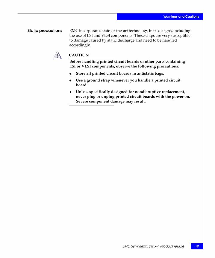
Static precautions EMC incorporates state-of-the-art technology in its designs, including the use of LSI and VLSI components. These chips are very susceptible to damage caused by static discharge and need to be handled accordingly.
CAUTION!Before handling printed circuit boards or other parts containing LSI or VLSI components, observe the following precautions:
◆ Store all printed circuit boards in antistatic bags.
◆ Use a ground strap whenever you handle a printed circuit board.
◆ Unless specifically designed for nondisruptive replacement, never plug or unplug printed circuit boards with the power on. Severe component damage may result.
EMC Symmetrix DMX-4 Product Guide 19

20
Warnings and Cautions
EMC Symmetrix DMX-4 Product Guide

Preface
As part of its effort to improve and enhance the performance and capabilities of the Symmetrix product line, EMC periodically releases revisions of the Symmetrix hardware and Enginuity Operating Environment. Therefore, some functions described in this guide may not be supported by all versions of Symmetrix hardware or Enginuity currently in use.
IMPORTANT!For the most up-to-date information on Symmetrix and Enginuity, refer to the “Symmetrix DMX-3, DMX-4 EMC Enginuity Release Notes”, located on EMC Powerlink.
If your Symmetrix DMX-4 does not function properly or does not function as described in this document, please contact your EMC representative.
Audience This product guide is part of the Symmetrix DMX-4 documentation of the Symmetrix DMX systems (referenced as DMX-4 in this product guide).
This product guide describes the Symmetrix DMX-4 features and operations. This product guide is intended for the storage administrator, system programmer, or operator who is involved in acquiring, managing, or operating the Symmetrix system.
Relateddocumentation
For additional information on all Symmetrix-related publications, contact your local EMC Sales Representative or refer to the EMC Powerlink website at:
http://Powerlink.EMC.com
EMC Symmetrix DMX-4 Product Guide 21

22
Preface
Conventions used inthis guide
EMC uses the following conventions for notes, cautions, warnings, and danger notices.
Note: A note presents information that is important, but not hazard-related.
CAUTION!A caution contains information essential to avoid damage to the system or equipment. The caution may apply to hardware or software.
WARNING
A warning contains information essential to avoid a hazard that can cause severe personal injury, death, or substantial property damage if you ignore the warning.
DANGER
A danger notice contains information essential to avoid a hazard that will cause severe personal injury, death, or substantial property damage if you ignore the message.
This product guide contains no DANGER messages.
EMC Symmetrix DMX-4 Product Guide

23
Preface
Typographicalconventions
EMC uses the following type style conventions in this guide.
Normal font In running text:• Interface elements (for example, button names, dialog box
names) outside of procedures• Items that user selects outside of procedures• Java classes and interface names• Names of resources, attributes, pools, Boolean expressions,
buttons, DQL statements, keywords, clauses, environment variables, filenames, functions, menu names, utilities
• Pathnames, URLs, filenames, directory names, computer names, links, groups, service keys, file systems, environment variables (for example, command line and text), notifications
Bold In procedures:• Names of dialog boxes, buttons, icons, menus, fields• Selections from the user interface, including menu items and
field entries• Key names• Window namesIn running text:• Command names, daemons, options, programs, processes,
notifications, system calls, man pages, services, applications, utilities, kernels
Italic Used for:• Full publications titles referenced in text• Unique word usage in text
Bold Italic Anything requiring extra emphasis
Courier Used for:• System output• Filenames• Complete paths• Command-line entries• URLs
Courier, bold Used for:• User entry• Options in command-line syntax
Courier, italic Used for:• Arguments used in examples of command-line syntax• Variables in examples of screen or file output• Variables in path names
Courier, bold, italic
Variables used in a command-line sample
< > Angle brackets enclose parameter or variable values supplied by the user
EMC Symmetrix DMX-4 Product Guide

24
Preface
Where to get help Obtain technical support by calling your local sales office.
Product information — For documentation, release notes, software updates, or for information about EMC products, licensing, and service, go to the EMC Powerlink website (registration required) at:
http://Powerlink.EMC.com
Technical support — For technical support, go to EMC WebSupport on Powerlink. To open a case on EMC WebSupport, you must be a WebSupport customer. Information about your site configuration and the circumstances under which the problem occurred is required.
Your comments Your suggestions will help us continue to improve the accuracy, organization, and overall quality of the user publications. Please send your opinion of this guide to:
[] Square brackets enclose optional values
| Vertical bar indicates alternate selections - the bar means “or”
{ } Braces indicate content that you must specify (that is, x or y or z)
... Ellipses indicate nonessential information omitted from the example
EMC Symmetrix DMX-4 Product Guide

1Invisible Body Tag
This chapter provides an overview of the Symmetrix DMX-4 and highlights the performance, availability and serviceability features, and hardware and software options:
◆ Symmetrix DMX-4 ............................................................................. 26◆ Symmetrix platform and Enginuity operating environment ...... 29◆ Storage capacities and global memory requirements................... 31◆ Performance features......................................................................... 33◆ Availability and integrity features................................................... 35◆ Serviceability features ....................................................................... 37◆ Supported software ........................................................................... 38◆ Hardware options .............................................................................. 41
Introducing theSymmetrix DMX-4
Introducing the Symmetrix DMX-4 25

26
Introducing the Symmetrix DMX-4
Symmetrix DMX-4The EMC® Symmetrix DMXTM systems are EMC’s family of high-end storage solutions. The DMX-4 model establishes a new performance and capacity trajectory for the highest of the high-end enterprise systems. The DMX-4 offers 4 Gb/s front-end and back-end that provides increased performance without increasing power and cooling. The point-to-point Fibre Channel backend has advanced disk isolation capabilities to improve serviceability.
The DMX-4 fully leverages the EMC industry-leading storage management functionality and introduces the economic benefits of scalable packaging to the high-end storage market.
The Symmetrix® DMX-4 is incrementally scalable, supporting from 96 to 1,920 2 Gb/s or 4 Gb/s high-performance Fibre Channel disk drives and 4 Gb/s SATA II drives, providing a maximum raw capacity of approximately 1 PB.
Note: For information on 2,400 drive support, contact your EMC Sales Representative.
To support the massive scalability of DMX-4 configurations, the DMX architecture has been expanded and improved to deliver higher throughput (1 GB/s links) and increased I/O performance (four dual 1.3 GHz PPC processor complexes per director). Table 1 on page 26 describes some of the Symmetrix DMX-4 performance features.
Table 1 Symmetrix DMX-4 performance features
Item Value Description
Data paths 32–128 8 per I/O director, 16 per global memory director
Data bandwidth 32–128 GB/s
Message bandwidth 4.0–6.4 GB/s
PowerPC processors 84–130 4 dual 1.3 GHz processor complexes per director
Global memory 16–512 GB a Available in 8, 16, 32, and 64 GB global memory directors
Concurrent Memory transfers 8–32 4 per global memory director
a. 256 GB effective
EMC Symmetrix DMX-4 Product Guide

Introducing the Symmetrix DMX-4
The field-proven Direct Matrix Architecture® (“Symmetrix DMX-4 architecture” on page 53) provides dedicated, nonblocking interconnects between I/O directors and global memory regions. Combined with expanded global memory director technology and the dynamically optimized caching algorithms of the Enginuity™ storage operating environment, systems based on the Symmetrix DMX architecture deliver scalable performance to meet the most demanding information access, protection, and distribution requirements.
Symmetrix DMX-4 configurations
The DMX-4 consists of a single system bay and from one to eight storage bays. The system bay contains the 24-slot card cage, service processor, power modules, and battery backup unit (BBU) assemblies. The storage bays contain disk drives and associated BBU modules. In a highly scalable component and cabinet configuration, the DMX-4 has the capacity, connectivity, and throughput to handle a wide range of high-end storage applications.
Figure 1 on page 27 provides a front view of the exterior of a Symmetrix DMX-4 configured with one system bay and eight storage bays. Figure 2 on page 28 provides a front view of the exterior of a Symmetrix DMX-4 configured with one system bay and four storage bays. Figure 3 on page 28 provides a front view of the exterior of a Symmetrix DMX-4 configured with one system bay and one storage bay.
Chapter 2, ”Symmetrix DMX-4 Hardware,” provides more complete descriptions of the Symmetrix DMX-4.
Figure 1 Symmetrix DMX-4 nine-bay configuration
Symmetrix DMX-4 27

28
Introducing the Symmetrix DMX-4
Figure 2 Symmetrix DMX-4 five-bay configuration
Figure 3 Symmetrix DMX-4 two-bay configuration
EMC Symmetrix DMX-4 Product Guide

29
Introducing the Symmetrix DMX-4
Symmetrix platform and Enginuity operating environment
Symmetrix platform and Enginuity operating environmentThe Symmetrix DMX hardware architecture (“Symmetrix DMX-4 architecture” on page 53) and the Enginuity operating environment are the foundation for the Symmetrix DMX system storage platform, which consists of the following:
◆ Symmetrix DMX hardware◆ Enginuity-based operating functions◆ EMC Solutions Enabler Application Program Interfaces (APIs)◆ Symmetrix-based applications◆ Host-based Symmetrix applications◆ Independent Software Vendor (ISV) applications
Figure 4 on page 29 illustrates the relationships among these software layers (and Symmetrix hardware).
Figure 4 Enginuity and the storage platform relationships
Enginuity operating environment
Symmetrix Enginuity is the operating environment for the Symmetrix DMX systems. Enginuity manages and ensures the optimal flow and integrity of information through the different hardware components of the Symmetrix system. Enginuity manages all Symmetrix operations from monitoring and optimizing internal data flow, to ensuring the fastest response to the user's requests for information, to protecting and replicating data.
Symmetrix hardware
EMC Solutions Enabler Applications Program Interface (API)
Symmetrix-based applications
Host-based Symmetrix applications
Independent software vendor applications
Enginuity operating environment functions

30
Introducing the Symmetrix DMX-4
Enginuity services Enginuity provides the following services for the Symmetrix DMX systems:
◆ Independently manages system resources to intelligently optimize performance across a wide range of I/O requirements.
◆ Ensures system availability through advanced fault monitoring, detection, and correction capabilities and provides concurrent maintenance and serviceability features.
◆ Interrupts and prioritizes tasks from microprocessors and, for example, ensures that fencing off failed areas takes precedence over other operations.
◆ Offers the foundation for specific software features available through EMC’s disaster recovery, business continuance, and storage management software.
◆ Provides functional services for both Symmetrix-based functionality and for a large suite of EMC storage application software.
◆ Defines priority of each task including basic system maintenance, I/O processing, application processing (for example, EMC ControlCenter®, SRDF®, TimeFinder®, and EMC ControlCenter Symmetrix Optimizer).
◆ Provides uniform access through APIs for internal calls and provides an external interface to allow integration with other software providers and ISVs.
EMC Solutions Enabler APIs
EMC Solutions Enabler APIs are the storage management programming interfaces that provide an access mechanism for managing the Symmetrix third-party storage, switches, and host storage resources. They enable the creation of storage management applications that don’t have to understand the management details of each piece within the total storage environment.
Note: For more information on EMC storage management APIs, contact your local EMC Sales Representative or refer to the Powerlink® website at: http://Powerlink.EMC.com
EMC Symmetrix DMX-4 Product Guide

Introducing the Symmetrix DMX-4
Storage capacities and global memory requirementsThis section describes the storage capacities and global memory requirements of the DMX-4 system.
Storage capacities The Symmetrix DMX-4 offers 73 GB, 146 GB, 300 GB, 400 GB, and 450 GB Fibre Channel drives, 73 GB, 146 GB Flash drives, 500 GB and 1 TB (terabyte) SATA II disk drives, and can be configured with from 96 to 1,920 disk drives.
The capacities are based on storage capacity of each disk drive type and the following storage protection options:
◆ Mirrored (RAID 1) ◆ RAID 10, RAID 1/0◆ SRDF ◆ RAID 5 (3+1) or RAID 5 (7+1)◆ RAID 6 (6+2) or RAID 6 (14+2))
Note: Appendix A, “Symmetrix DMX-4 Specifications,” contains additional information on drive and system capacities.
Factors affecting storage capacity
The following factors affect disk storage capacity:
◆ Drive capacity size.
◆ Type of data protection options used.
◆ Internal Symmetrix File System (SFS) usage — A Symmetrix DMX-4 reserves two SFS logical volumes consisting of 6,140 cylinders each (slightly less than 6 GB). These volumes are protected using mirroring, consuming slightly less than 24 GB total physical space.
◆ The size of the blocks — 512 or 520 bytes per block.
◆ Vault devices — Symmetrix DMX-4 uses vault devices for vaulting data from global memory during a power-down operation. Vault devices require 5 GB of space. For each pair of disk directors in a DMX-4, 160 GB of total capacity is reserved for vaulting data from memory during system powerdown.
Note: “Configuration rules for vault devices” on page 70 and “Vaulting” on page 169 contain additional information.
Storage capacities and global memory requirements 31

32
Introducing the Symmetrix DMX-4
Global memory requirements
The Symmetrix DMX-4 is available with global memory capacity ranging from 16 GB to 512 GB (256 GB effective). The total global memory requirement for a Symmetrix DMX-4 is based upon specific system configurations and customer requirements. Besides the customer’s applications, other variables that affect the amount of global memory a Symmetrix DMX-4 requires include the following:
◆ Number of global memory directors
◆ Variable back-end disk director and front-end channel director board configurations
◆ Various loop configurations for disk drives
◆ Number of disk drives
◆ Disk capacity, including speed and protection type
◆ Number of logical volumes
Your local EMC Sales Representative will assist you in determining your global memory requirements.
Note: “Global memory directors” on page 84 provides additional information on memory configurations.
EMC Symmetrix DMX-4 Product Guide

33
-4
Performance features
Introducing the Symmetrix DMX
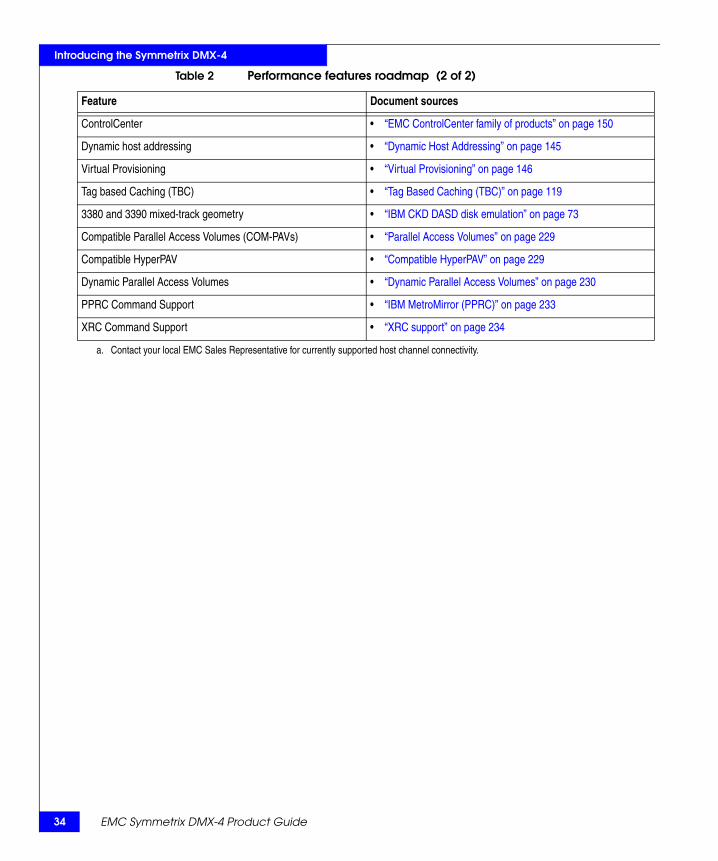
Performance featuresSymmetrix DMX-4 offers improved performance over conventional Storage Control Unit (SCU) and Direct Access Storage Device (DASD) designs. Table 2 on page 33 identifies many of the Symmetrix DMX-4 and Enginuity supported features that enhance performance and increase throughput.
Table 2 Performance features roadmap (1 of 2)
Feature Document sources
Direct Matrix (DMX) Architecture with up to 128 direct nonblocking data paths and up to 128 GB/s aggregate internal bandwidth in the DMX-4
• “Symmetrix DMX-4” on page 26 and “Symmetrix DMX-4 architecture” on page 53
• “Symmetrix DMX-4 and component scaling attributes” on page 50
• “DMX-4 point-to-point message matrix” on page 55
Symmetrix DMX-4 global memory directors for optimized performance
• “Global memory performance features” on page 117• “Memory striping” on page 118• “Global memory directors” on page 84• “Global memory director configuration” on page 86
One hundred percent global memory fast write capabilities • “Write operations” on page 110• “Disk mirroring (RAID 1) concepts” on page 191
PermaCache option • “PermaCache option” on page 121
4 Gb/s Fibre Channel drive infrastructure • “Fibre Channel disk subsystem” on page 62
4 Gb/s SATA II drives • “SATA II drives” on page 63
2 Gb/s 73 GB, 146 GB Flash solid state drives • “Flash drives” on page 64
• Multiple scalable channel directors, disk directors, and global memory directors a
• ESCON channel speeds up to 17 MB/s• FICON channel speeds up to 4 Gb/s• Fibre Channel speeds up to 4 Gb/s• iSCSI channel speeds up to 1 Gb/s• Gigabit Ethernet (GigE) remote director speeds up to 1 Gb/s• GigE IPv4/v6 (IPsec capable) channel speeds up to 1 Gb/s• FICON Cascading and Open Systems Intermix Configurations
• “Channel, disk, and global memory directors” on page 76• “ESCON channel directors” on page 80• “FICON channel director” on page 81• “Fibre Channel directors front-end” on page 78• “iSCSI channel directors” on page 83• “Gigabit Ethernet (GigE) remote directors” on page 82• “GigE IPv4/v6 (IPsec capable) channel director” on page 83• “Symmetrix FICON configurations” on page 95• “FICON Cascading and Open Systems Intermix
configurations” on page 236
Logical volume capacities • “Symmetrix DMX-4 logical volume capacities” on page 68
Hypervolume Extension option • “Open systems hypervolumes” on page 127• “Mainframe systems hypervolumes” on page 132
Tiered storage optimization • “Symmetrix Priority Controls” on page 136• “Dynamic Cache Partitioning” on page 137
Virtual LUNs • “Virtual LUN technology” on page 140
34
Introducing the Symmetrix DMX-4
EMC Symmetrix DMX-4 Product Guide
ControlCenter • “EMC ControlCenter family of products” on page 150
Dynamic host addressing • “Dynamic Host Addressing” on page 145
Virtual Provisioning • “Virtual Provisioning” on page 146
Tag based Caching (TBC) • “Tag Based Caching (TBC)” on page 119
3380 and 3390 mixed-track geometry • “IBM CKD DASD disk emulation” on page 73
Compatible Parallel Access Volumes (COM-PAVs) • “Parallel Access Volumes” on page 229
Compatible HyperPAV • “Compatible HyperPAV” on page 229
Dynamic Parallel Access Volumes • “Dynamic Parallel Access Volumes” on page 230
PPRC Command Support • “IBM MetroMirror (PPRC)” on page 233
XRC Command Support • “XRC support” on page 234
a. Contact your local EMC Sales Representative for currently supported host channel connectivity.
Table 2 Performance features roadmap (2 of 2)
Feature Document sources

Introducing the Symmetrix DMX-4
Availability and integrity featuresThe Symmetrix DMX-4 includes key enhancements that improve the reliability, availability, and serviceability. Table 3 on page 35 highlights many of the Symmetrix DMX-4 availability and integrity features.
Table 3 Availability and integrity features roadmap (1 of 2)
Feature Document sources
Proactive Error Detection and Remote Support • “Maintaining data integrity” on page 175• “Error Checking and Correction, and data integrity protection”
on page 176• “Disk error correction and error verification” on page 177• “Global memory director data integrity logic” on page 178
Support for online Enginuity upgrades and updates • “Nondisruptive Enginuity upgrades” on page 173
Fully fault-tolerant design with redundant critical components and concurrent maintenance support
• “Reliability and availability features” on page 162
Channel director redundancy with end-to-end automatic channel failover and load balancing
• “Channel director redundancy” on page 163
Internal Control Data Path redundancy • “Internal control data path redundancy” on page 164
Fibre Channel back-end functionality featuring redundant disk directors, disk channels, and disk ports
• “Fibre Channel back-end redundancy” on page 164• “Fibre Channel arbitrated loop design” on page 165
Dual-initiator disk directors • “Dual-initiator feature” on page 168
2N power supply redundancy • “Redundant power subsystem” on page 169
Vaulting • “Configuration rules for vault devices” on page 70• “Vaulting” on page 169
Redundant Global Memory • “Redundant global memory” on page 162
Advanced Communications and Environmental Control Modules
• “DMX-4 communications and environmental control” on page 90
DMX-4 security features • “Symmetrix Service Credential, Secured by RSA” on page 182• “Symmetrix Audit Log” on page 185• “RSA enVision log security” on page 185• “EMC Certified Data Erasure for Symmetrix Disks” on page 186• “IPsec security features” on page 187
Symmetrix Mirroring option • “Disk mirroring (RAID 1) concepts” on page 191
Availability and integrity features 35

36
Introducing the Symmetrix DMX-4
RAID 5 (3+1), RAID 5 (7+1)RAID 6 (6+2), RAID 6 (14+2)RAID 10 data protection options
• “Symmetrix DMX RAID 5” on page 198• “Symmetrix DMX RAID 6” on page 206• “Symmetrix RAID 10 for mainframe systems” on page 196
Sparing option • “Dynamic sparing” on page 215• “Permanent sparing” on page 212
TimeFinder • “TimeFinder family of products” on page 154
SRDF • “Base SRDF family products” on page 219• “SRDF family options” on page 220
• Nondisruptive component replacement • Nondisruptive change or remove drives
• “Nondisruptive component replacement” on page 172• “Nondisruptively change or remove drives” on page 174
Table 3 Availability and integrity features roadmap (2 of 2)
Feature Document sources
EMC Symmetrix DMX-4 Product Guide

37
Introducing the Symmetrix DMX-4
Serviceability features
Serviceability featuresEach Symmetrix DMX-4 has an integrated service processor that continuously monitors the Symmetrix environment. The service processor communicates with the EMC Customer Support Center through a customer-supplied direct phone line. The service processor automatically dials the Customer Support Center whenever the Symmetrix system detects a component failure or environmental violation. An EMC Product Support Engineer at the Customer Support Center can also run diagnostics remotely through the service processor to determine the source of a problem and potentially resolve it before the problem becomes critical. Within the DMX-4 control e-net matrix is the Communications and Environmental Control Module, known as the XCM. The XCM provides the low-level system-wide communications for running application software, monitoring, and system diagnostics from the service processor.
Symmetrix DMX systems feature an incrementally scalable design with a low parts count for quick component replacement, should a failure occur. This low parts count minimizes the number of failure points. The Symmetrix DMX systems feature nondisruptive replacement of its major components, which can be replaced while the Symmetrix system is powered on, including:
◆ Channel directors◆ Disk directors◆ Global memory directors◆ Disk adapters◆ Channel adapters◆ Disk drives◆ Power supplies◆ Power distribution units (PDU)◆ Power distribution panels (PDP)◆ Power supply/ cooling module for drive enclosure◆ Battery backup modules◆ Cooling fan modules◆ Communications and Environmental Control (XCM) modules◆ Service processor components:
• Keyboard• Video Display and Mouse
Note: Chapter 2, ”Symmetrix DMX-4 Hardware,” and “Nondisruptive component replacement” on page 172 provide more information on these components.

38
Introducing the Symmetrix DMX-4
Supported softwareEnginuity is what enables simultaneous connection to virtually all mainframe, UNIX, Windows, iSeries, and Linux platforms—and all validated in EMC’s interoperability labs. The result: you can do whatever you want with your information. Centralize it. Re-purpose it. Consolidate it. Replicate it. Share it. Distribute and manage it. Put it to work where it’s relevant, anytime without compromise.
Enginuity is the solid foundation of EMC’s storage software offering—and the driving force behind the operational consistency and nondisruptive features across Symmetrix.
The software offerings are divided into these categories:
◆ “Tiered storage optimization” on page 38
◆ “Storage management” on page 39
◆ “Symmetrix local and remote replication software solutions” on page 39
◆ “Information mobility” on page 40
Note: Product information on these software options are available on the EMC Powerlink website at: http://Powerlink.EMC.com
All of the software products are furnished under a license. Refer to the copyright page in this product guide for the complete licensing statement. For software license, model numbers, prerequisites, and additional information, contact your local EMC Sales Representative.
Tiered storage optimization
EMC delivers two software products with the latest version of Enginuity (5772) that optimize performance with multi-tiered Symmetrix systems. Dynamic Cache Partitioning provides dedicated memory resource allocation. Symmetrix Priority Controls help manage multiple application workloads by setting priority levels for device groups, allowing higher-priority applications to have faster response times than lower priority applications.
Note: “Tiered storage optimization” on page 136 contains related information.
EMC Symmetrix DMX-4 Product Guide

Introducing the Symmetrix DMX-4
Storage management
Storage Management Console is an intuitive, browser-based GUI for Symmetrix device management for open systems as well as z/OS-attached systems. Symmetrix Management Console features management and monitoring of local and remote replication, as well as the tiered storage optimization tools Symmetrix Priority Controls and Dynamic Cache Partitioning.
The EMC ControlCenter family of storage management software provides automated management of your multi-vendor networked storage environment through a single, consistent, information-centric approach.
EMC z/OS Storage Manager (EzSM) is a mainframe software product providing discovery and viewing of your Symmetrix environment. EzSM provides facilities to handle volumes, data sets, catalogs, and detailed Symmetrix functionality information.
Note: “EMC ControlCenter family of products” on page 150 contains related information.
Symmetrix local and remote replication software solutions
The EMC TimeFinder and SRDF families of software are the most powerful suites of local and remote storage replication solutions available in the industry; enabling business continuance volumes for parallel processing activities like backup, testing and development, and local restore, as well as remotely replicated copies to guard against primary site disasters and outages.
Note: “TimeFinder family of products” on page 154 contains related information. “Base SRDF family products” on page 219 and “SRDF family options” on page 220 contains related information.
Supported software 39

40
Introducing the Symmetrix DMX-4
Information mobility Copy and move data to where it provides the most value. Symmetrix DMX enables online data mobility and migration while minimizing complexity and disruption. Move data between storage tiers, platforms, and sites quickly, efficiently, and without disruption:
◆ EMC Open Migrator/LM — Provides host-based, nondisruptive data migration/data mobility at the volume level for Microsoft Windows and UNIX servers.
◆ EMC Open Replicator for Symmetrix — Enables remote point-in-time copies to be used for high-speed data mobility, remote vaulting, migrations, and distribution between EMC Symmetrix DMX and qualified storage systems with full or incremental copy capabilities.
◆ SRDF/Data Mobility (DM) — Enables rapid transfer of data from source volumes to remote volumes anywhere in the world.
Note: Product information on these software options are available on the EMC Powerlink website at: http://Powerlink.EMC.com
“Base SRDF family products” on page 219 and “SRDF family options” on page 220 contain related information.
EMC Symmetrix DMX-4 Product Guide

Introducing the Symmetrix DMX-4
Hardware optionsThe following hardware options are offered with the DMX-4 systems:
◆ DMX-4 Silencer
◆ DMX-4 systems securing kits
DMX-4 Silencer The Symmetrix DMX-4 Silencer as shown in Figure 5 on page 41 is a fan noise reduction option for the Symmetrix DMX-4 system bay and storage bay systems. The Symmetrix DMX-4 Silencer is designed with leading edge sound reducing materials that attenuate high-frequency noise components and reduce overall sound levels. It is designed not to affect airflow or thermal performance.
Figure 5 DMX-4 Silencer
Titan Titan
SYM-001247
Storage Bay (Mohawk)
SYMMETRIX
E M C 2
PS1
PS2
PS3
PS4
PS5
PS6
PS7
PS8
System Bay (Titan)
E M C
2
Hardware options 41

42
Introducing the Symmetrix DMX-4
Table 4 on page 42 provides the DMX-4 Silencer kits model information.
The DMX-4 Silencer kit contains the following components:
◆ DMX-4 Silencer for top of system bay and or storage bay
◆ Full length foam piece for the storage bay
◆ An 11-in. by 20-in. foam piece for the system bay
Note: Contact your EMC Sales Representative for Silencer kit information and current availability.
DMX-4 Silencer specifications
Table 5 on page 42 lists the dimensions and weight for the DMX-4 Silencer for the system bay and storage bay.
Table 4 DMX-4 Silencer kits model information
Model number Description Comments
Contact your EMC Sales Representative for model number information.
System bay silencer kit 1 kit per bay
Contact your EMC Sales Representative for model number information.
Storage bay silencer kit 1 kit per bay
Table 5 DMX-4 Silencer physical specifications
DMX-4 system Physical characteristics
DMX-4 silencer for system bay Dimensions:HeightWidthDepth
Inches8.252336.5
Centimeters20.9658.4292.71
Weight Pounds10
Kilograms4.54
DMX-4 silencer for storage bay Dimensions:HeightWidthDepth
Inches6.52936.5
Centimeters16.5173.66 92.71
Weight Pounds9.4
Kilograms4.26
EMC Symmetrix DMX-4 Product Guide

Introducing the Symmetrix DMX-4
Table 49 on page 268 lists the sound power and sound pressure levels for the DMX-4 system bay and storage bays.
DMX-4 systems securing kits
Some customers require that their EMC equipment be installed to withstand significant shock and vibration. Installation of EMC Symmetrix DMX-4 systems securing kits in combination with adequate substrate construction, will mitigate collateral damage during such events.
The kits contain heavy brackets plus hardware used to attach the brackets to the frames of the system and storage bays. The brackets are attached to the floor using bolts that engage the flooring substructure provided by the user.
Symmetrix DMX-4 systems securing kits can be installed to system and storage bays without lifting the bays.
Note: The EMC Symmetrix DMX-4 Physical Planning Guide contains related information regarding the EMC securing kits, or contact your EMC Sales Representative for specific information.
Hardware options 43

44
Introducing the Symmetrix DMX-4
EMC Symmetrix DMX-4 Product Guide

2Invisible Body Tag
This chapter describes the main hardware components of the Symmetrix DMX-4 including:
◆ Major components ............................................................................. 46◆ Symmetrix DMX-4 architecture ....................................................... 53◆ Symmetrix channel connectivity and host integration................. 59◆ Fibre Channel disk subsystem ......................................................... 62◆ Channel, disk, and global memory directors................................. 76◆ Symmetrix DMX-4 power subsystems ........................................... 87◆ DMX-4 communications and environmental control ................... 90◆ Channel attachments ......................................................................... 93
Symmetrix DMX-4Hardware
Symmetrix DMX-4 Hardware 45

46
Symmetrix DMX-4 Hardware
Major componentsThe Symmetrix DMX-4 is a disk array subsystem that is composed of a system bay and from one to eight storage bays (Table 6 on page 46). This section describes the Symmetrix DMX-4 components.
WARNING
To reduce the risk of personal injury, do not open the doors or move the Symmetrix DMX-4 unless you are qualified and familiar with safety procedures for electrical equipment and the Symmetrix DMX-4. The Symmetrix DMX-4 contains no user-serviceable parts. Neither the system bay nor the storage bays should not be moved or opened for any reason by untrained persons. If the Symmetrix DMX-4 is in need of relocation or repair, only qualified personnel should access components inside the bays or move them.
Table 6 Symmetrix DMX-4 model component overview
Symmetrix DMX-4 components Component information location
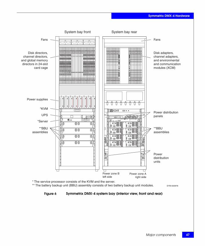
Main component locations of the system bay, front and rear views Figure 6 on page 47
Main component descriptions of the system bay Table 7 on page 48
Main component locations of the storage bay, front and rear views Figure 7 on page 49
Main component descriptions of the storage bay Table 8 on page 50
EMC Symmetrix DMX-4 Product Guide
Symmetrix DMX-4 Hardware
Figure 6 Symmetrix DMX-4 system bay (interior view, front and rear)
PS1 PS2 PS3 PS4 PS5 PS6 PS7 PS8
LAN1
LAN2
PS8 PS7 PS6 PS5 PS4 PS3 PS2 PS1
ON I
OFF O
ON I
OFF O
ON I
OFF O
ON I
OFF O
ON I
OFF O
ON I
OFF O
Fans Fans
Power supplies
*KVM
UPS
*Server
SYM-000978
Power zone Bleft side
Power zone Aright side
Disk directors,channel directors,
and global memorydirectors in 24-slot
card cage
**BBUassemblies
**BBUassemblies
Disk adapters,channel adapters,and environmental and communicationmodules (XCM)
Power distributionpanels
Powerdistributionunits
System bay front System bay rear
* The service processor consists of the KVM and the server.** The battery backup unit (BBU) assembly consists of two battery backup unit modules.
Major components 47

48
Symmetrix DMX-4 Hardware
Table 7 Symmetrix DMX-4 system bay component overview
Component Description
Cooling Fan Modules Three 3-fan modules maintain air circulation and cool the unit internally.
Card Cage and Midplane The front 24 slots contain global memory directors, disk directors, and channel directors (front-end Fibre Channel, ESCON, FICON, and iSCSI channel directors a, or GigE Remote directors). The rear slots contain the channel host adapters, GigE Remote adapters, disk adapters, and the Communications and Environmental Control Modules (XCMs).
Channel Directors/Adapters and Remote Director Adapters(Front-End) a
Up to 12 channel directors connect to the front side of the midplane and the adapters to the rear side of the midplane in the system cabinet. Each channel director’s adapter provides the interface to the host or network.
Fibre Channel Disk Directors/Adapters (Back-End)
Two, four, six, or eight disk directors connect to the midplane in the front of the cabinet. Each disk director’s adapter provides the interface to the Fibre Channel disk drives. The adapter connects to the opposite side of the midplane in the rear of the cabinet.
Global Memory Directors Two, four, six, or eight global memory directors provide up to 512 GB (256 GB effective) total global memory, available in 8 GB, 16 GB, 32 GB, and 64 GB global memory director capacities.
Communications and Environmental Control Module (XCM)
Two communications and environmental control modules (XCMs) connect to the midplane in the rear card cage. The XCM contains the Ethernet interface between the directors (channel, disk, and memory) and the service processor. It monitors and logs environmental events for all Symmetrix DMX-4 FRUs (field replacable units) and reports any operational problems such as thermal excursion, voltage drop. It also has connectors for paths between the XCM and the BBU modules (in the system bay and the storage bays) for sending commands and receiving status.
Power Supplies Up to eight power supplies support the system bay and are split between two (A and B) three-phase power zones. Each zone supports up to four power supplies. One zone can maintain power for the entire system bay independent of the power supplies in the other zone. The DMX-4 is available in three-phase Delta or three-phase WYE configurations.
Power Distribution Panel (PDP), Power Distribution Unit (PDU), and AC connectors
Two PDPs, one for each zone, provide a centralized cabinet interface and distribution control of the AC power input lines when connected to the system bay PDUs. The PDPs contain the manual On/Off power switches, which are accessible through the rear door. The PDUs, one for each power zone, provide the main interface between the input AC from the PDPs and the various components contained within the system bay.
Battery Backup Unit (BBU) Assembly consisting of two BBU modules
Up to eight BBU modules provide backup for each of the power supplies. If AC power fails, the BBU modules can maintain power for two five minute periods of AC loss while the Symmetrix system shuts down.
Service Processor (Keyboard, Video Display, and Mouse - KVM), server, and Uninterruptible Power Supply (UPS)
The service processor consists of a KVM and a server that connects to the Symmetrix subsystem through an Ethernet interface. The service processor uses an external modem for communicating with the EMC Customer Support Center when the Symmetrix system detects an error condition. The service processor is used to download the Symmetrix system configuration to the directors and provides diagnostic and maintenance utilities for the Symmetrix system. The server battery backup is provided by a UPS.
a. Contact your local EMC Sales Representative for current channel director availability.
EMC Symmetrix DMX-4 Product Guide

Symmetrix DMX-4 Hardware
Figure 7 Symmetrix DMX-4 storage bay (interior view, front and rear)
! !
!!
!
EX
PP
RI
EX
PP
RI
#
!
EX
PP
RI
EX
PP
RI
#
A B
! !
!!
!
EX
PP
RI
EX
PP
RI
#
!
EX
PP
RI
EX
PP
RI
#
A B
! !
!!
!
EX
PP
RI
EX
PP
RI
#
!
EX
PP
RI
EX
PP
RI
#
A B
! !
!!
!
EX
PP
RI
EX
PP
RI
#
!
EX
PP
RI
EX
PP
RI
#
A B
ONI
OFFO
ONI
OFFO
ONI
OFFO
ONI
OFFO
ONI
OFFO
ONI
OFFO
! !
!!
!
EX
PP
RI
EX
PP
RI
#
!
EX
PP
RI
EX
PP
RI
#
A B
! !
!!
!
EX
PP
RI
EX
PP
RI
#
!
EX
PP
RI
EX
PP
RI
#
A B
! !
!!
!
EX
PP
RI
EX
PP
RI
#
!
EX
PP
RI
EX
PP
RI
#
A B
! !
!!
!
EX
PP
RI
EX
PP
RI
#
!
EX
PP
RI
EX
PP
RI
#
A B
! !
!!
!
EX
PP
RI
EX
PP
RI
#
!
EX
PP
RI
EX
PP
RI
#
A B
! !
!!
!
EX
PP
RI
EX
PP
RI
#
!
EX
PP
RI
EX
PP
RI
#
A B
! !
!!
!
EX
PP
RI
EX
PP
RI
#
!
EX
PP
RI
EX
PP
RI
#
A B
! !
!!
!
EX
PP
RI
EX
PP
RI
#
!
EX
PP
RI
EX
PP
RI
#
A B
! !
!!
!
EX
PP
RI
EX
PP
RI
#
!
EX
PP
RI
EX
PP
RI
#
A B
! !
!!
!
EX
PP
RI
EX
PP
RI
#
!
EX
PP
RI
EX
PP
RI
#
A B
! !
!!
!
EX
PP
RI
EX
PP
RI
#
!
EX
PP
RI
EX
PP
RI
#
A B
! !
!!
!
EX
PP
RI
EX
PP
RI
#
!
EX
PP
RI
EX
PP
RI
#
A B
Power supply/system coolingmodule
Power distributionunits (PDU)
Link controlcards
Disk drives(15 per column)
Disk drivescovers
Green LED4 GB mode
blue LED2 GB mode
Batterybackup
unit cover
Batterybackup
unit (BBU)
Storage bay frontBatterybackupunit (BBU)
SYM-001418
Storage bay rear
Power distributionpanels (PDP)
Power zone Bleft side
Power zone Aright side
Major components 49
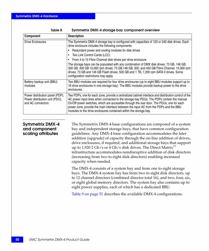
50
Symmetrix DMX-4 Hardware
Symmetrix DMX-4 and component scaling attributes
The Symmetrix DMX-4 base configurations are composed of a system bay and independent storage bays, that have common configuration guidelines. Any DMX-4 base configuration accommodates the later addition (upgrade) of capacity through the on-line addition of drives, drive enclosures, if required, and additional storage bays that support up to 1,920 2 Gb/s or 4 Gb/s disk drives. The Direct Matrix™
infrastructure accommodates nondisruptive addition of disk directors (increasing from two to eight disk directors) enabling increased capacity when needed.
The DMX-4 consists of a system bay and from one to eight storage bays. The DMX-4 system bay has from two to eight disk directors, up to 12 channel directors (combined director total 16), and two, four, six, or eight global memory directors. The system bay also contains up to eight power supplies, each of which has a dedicated BBU.
Table 9 on page 51 describes the available DMX-4 configurations.
Table 8 Symmetrix DMX-4 storage bay component overview
Component Description
Drive Enclosures The Symmetrix DMX-4 storage bay is configured with capacities of 120 or 240 disk drives. Each drive enclosure includes the following components:• Redundant power and cooling modules for disk drives• Two Link Control Cards (LCC) • From 4 to 15 Fibre Channel disk drives per drive enclosureThe storage bays can be populated with any combination of DMX disk drives: 73 GB, 146 GB, 300 GB, 400 GB 10,000 rpm drives; 73 GB,146 GB, 300, and 450 GB Fibre Channel, 15,000 rpm drives; 73 GB and 146 GB Flash drives; 500 GB and 1 TB, 7,200 rpm SATA II drives. Some configuration restrictions may apply.
Battery backup unit (BBU) modules
Two BBU modules are required for four drive enclosures (up to eight BBU modules support up to 16 drive enclosures in one storage bay). The BBU modules provide backup power to the drive enclosures.
Power distribution panel (PDP), Power distribution unit (PDU), and AC connectors
Two PDPs, one for each zone, provide a centralized cabinet interface and distribution control of the AC power input lines when connected to the storage bay PDUs. The PDPs contain the manual On/Off power switches, which are accessible through the rear door. The PDUs, one for each power zone, provide the main interface between the input AC from the PDPs and the BBU modules to the drive enclosures contained within the storage bay.
EMC Symmetrix DMX-4 Product Guide

Symmetrix DMX-4 Hardware
DMX-4 configuration rules and guidelines
The following are some of the system configuration rules and guidelines to consider when planning your new or upgrading your DMX-4 system:
◆ All bays must be configured in an inline installation. Each bay is bolted to the adjacent bay during installation.
◆ Storage bays can be populated with any combination of 73 GB, 146 GB, 300 GB, and 400 GB 10,000 rpm drives, 73 GB, 146 GB, 30 GB, and 450 GB 15,000 rpm drives, 73 GB and 146 GB Flash drives, 500 GB and 1 TB 7,200 rpm drives. Some restrictions may apply.
◆ A minimum of four disk drives must be configured in each drive enclosure.
Table 9 DMX-4 configurations
Number of disk directors 2 disk directors 4 disk directors 6 disk directors 8 disk directors
Drive channels 8 16 24 32
Minimum and maximum number of disk drives 96–240 192–960 360–1,440 480–1,920
Minimum and maximum TB capacity (raw)a
a. Minimum raw capacity for a DMX-4 is based on 73 GB disk drives. Maximum capacity is based on 1 TB disk drives.
7.04–239.86 14.08–959.44 26.40–1,439.16 35.21–1,918.88
Maximum TB capacity (protected)b
b. Maximum protected capacity for a DMX-4 is based on 1 TB drives and RAID 5 (7+1) data protection with currently available memory.
145.17 328.81 475.72 585.91
Maximum global memory (usable) 64 GB 144 GB 216 GB 256 GB
Usable connectivityc
c. Combinations may be limited or restricted.
48 x 4 Gb/s Fibre Channel
64 x 4 Gb/s Fibre Channel
64 x 4 Gb/s Fibre Channel
64x 4 Gb/s Fibre Channel
24 x 4 Gb/s FICON 48 x 4 Gb/s FICON 40 x 4 Gb/s FICON 32 x 4 Gb/s FICON
48 ESCON 64 ESCON 64 ESCON 64 ESCON
8 x 1 Gb/s Ethernet remote replication
8 x 1 Gb/s Ethernet remote replication
8 x 1 Gb/s Ethernet remote replication
8 x 1 Gb/s Ethernet remote replication
24 x 1 Gb/s Gigabit Ethernet iSCSI
48 x 1 Gb/s Gigabit Ethernet iSCSI
40 x 1 Gb/s Gigabit Ethernet iSCSI
32 x 1 Gb/s Gigabit Ethernet iSCSI
Major components 51
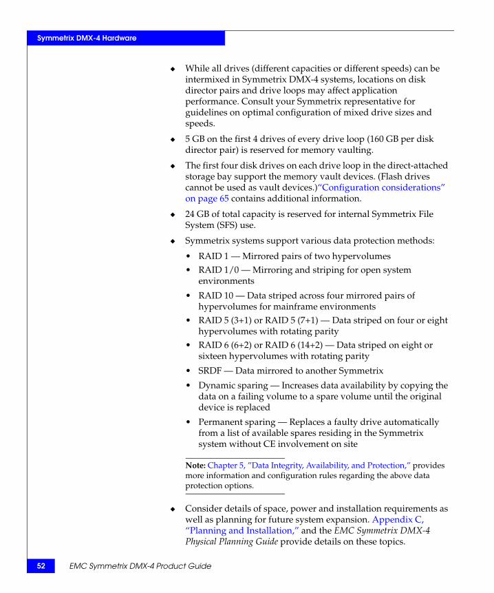
52
Symmetrix DMX-4 Hardware
◆ While all drives (different capacities or different speeds) can be intermixed in Symmetrix DMX-4 systems, locations on disk director pairs and drive loops may affect application performance. Consult your Symmetrix representative for guidelines on optimal configuration of mixed drive sizes and speeds.
◆ 5 GB on the first 4 drives of every drive loop (160 GB per disk director pair) is reserved for memory vaulting.
◆ The first four disk drives on each drive loop in the direct-attached storage bay support the memory vault devices. (Flash drives cannot be used as vault devices.)“Configuration considerations” on page 65 contains additional information.
◆ 24 GB of total capacity is reserved for internal Symmetrix File System (SFS) use.
◆ Symmetrix systems support various data protection methods:
• RAID 1 — Mirrored pairs of two hypervolumes• RAID 1/0 — Mirroring and striping for open system
environments
• RAID 10 — Data striped across four mirrored pairs of hypervolumes for mainframe environments
• RAID 5 (3+1) or RAID 5 (7+1) — Data striped on four or eight hypervolumes with rotating parity
• RAID 6 (6+2) or RAID 6 (14+2) — Data striped on eight or sixteen hypervolumes with rotating parity
• SRDF — Data mirrored to another Symmetrix
• Dynamic sparing — Increases data availability by copying the data on a failing volume to a spare volume until the original device is replaced
• Permanent sparing — Replaces a faulty drive automatically from a list of available spares residing in the Symmetrix system without CE involvement on site
Note: Chapter 5, ”Data Integrity, Availability, and Protection,” provides more information and configuration rules regarding the above data protection options.
◆ Consider details of space, power and installation requirements as well as planning for future system expansion. Appendix C, “Planning and Installation,” and the EMC Symmetrix DMX-4 Physical Planning Guide provide details on these topics.
EMC Symmetrix DMX-4 Product Guide

Symmetrix DMX-4 Hardware
Symmetrix DMX-4 architectureThe Symmetrix DMX-4 features a high-performance, Direct Matrix Architecture (DMX) supporting up to 128 point-to-point serial connections within the DMX system.
Symmetrix DMX technology is distributed across all channel directors, disk directors, and global memory directors in Symmetrix DMX systems. Enhanced global memory technology supports multiple regions and 16 connections on each global memory director. In the Direct Matrix Architecture, contention is minimized because control information and commands are transferred across a separate and dedicated message matrix. The major components of Symmetrix DMX architecture are the front-end channel directors (and their interface adapters), global memory directors, and back-end disk directors (and their interface adapters).
The matrix midplane provides configuration flexibility through the slot configuration. Each director slot port is hard-wired point-to-point to one port on each global memory director board.
This section includes the following topics:
◆ “DMX-4 block diagram” on page 53◆ “DMX-4 point-to-point message matrix” on page 55◆ “DMX-4 slot configuration” on page 56
DMX-4 block diagram
In a fully configured Symmetrix DMX-4, each of the eight director ports on the 16 directors connects to one of the 16 memory ports on each of the eight global memory directors. These 128 individual point-to-point connections facilitate up to 128 concurrent global memory operations in the system. Figure 8 on page 54 illustrates the point-to-point architecture and the interconnection of the major components of the Symmetrix DMX-4 systems.
Symmetrix DMX-4 architecture 53
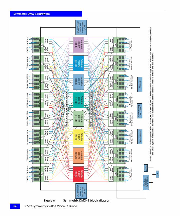
54
Symmetrix DMX-4 Hardware
Figure 8 Symmetrix DMX-4 block diagram
Bat
tery
bac
kup
unit
odul
es
Coo
ling
ES
CO
N D
irec
tor
ES
CO
N H
ost
Att
a c h
Dir
ect
Mat
rix
Dir
ect
Mat
rix
FC
Dir
ecto
r
FC
Ho
st A
tta c
h
Dir
ect
Mat
rix
Dir
ect
Mat
rix
Mu
ltiP
r oto
col C
D
Dir
ect
Mat
rix
Dir
ect
Mat
rix
Mu
ltiP
r oto
col C
D
FIC
ON
, Gig
E , i
SC
S I
Dir
ect
Mat
rix
Dir
ect
Mat
rix
Mu
ltiP
r oto
col C
D
FIC
ON
, Gig
E , i
SC
S I
Dir
ect
Mat
rix
Dir
ect
Mat
rix
Mu
ltiP
r oto
col C
D
FIC
ON
, Gig
E , i
SC
S I
Dir
ect
Mat
rix
Dir
ect
Mat
rix
FC
Dir
ecto
r
FC
Ho
st A
tta c
h
Dir
ect
Mat
rix
Dir
ect
Mat
rix
ES
CO
N D
irec
tor
ES
CO
N H
ost
Att
a c h
Dir
ect
Mat
rix
Dir
ect
Mat
rix
Cn
tl
FC
(B
a c k-
En
d )
Sym
met
rix
FC
dis
k d
e vic
e s
Dir
ect
Mat
rix
Dir
ect
Mat
rix
Cn
tl
FC
(B
a c k-
En
d )
Sym
met
rix
FC
Dis
k D
e vic
e s
Dir
ect
Mat
rix
Dir
ect
Mat
rix
Cn
tl
FC
(B
E o
r F
E)
Sym
met
rix
F
C d
isk
dev
ices
*
Dir
ect
Mat
rix
Dir
ect
Mat
rix
Cn
tl
FC
(B
E o
r F
E)
Sym
met
rix
F
C d
isk
dev
ices
*
Dir
ect
Mat
rix
Dir
ect
Mat
rix
Cn
tl
FC
(B
E o
r F
E)
Sym
met
rix
F
C d
isk
de v
ices
*
Dir
ect
Mat
rix
Dir
ect
Mat
rix
Cn
tl
FC
(B
E o
r F
E)
Sym
met
rix
F
C d
isk
de v
ices
*
Dir
ect
Mat
rix
Dir
ect
Mat
rix
Cn
tl
FC
(B
a c k-
En
d )
Sym
met
rix
FC
dis
k d
e vic
e s
Dir
ect
Mat
rix
Dir
ect
Mat
rix
Cn
tl
FC
(B
a c k-
En
d )
Sym
met
rix
FC
dis
k d
e vic
e s
Dir
ect
Mat
rix
Dir
ect
Mat
rix
Cn
tl
Cn
tl
Cn
tl
Cn
tl
Cn
tl
Cn
tl
Cn
tl
Cn
tl
Co
nt r
ol a
nd
co
mm
un
icat
ion
s si
gn
als
Co
nt r
ol a
nd
co
mm
un
icat
ion
s si
gn
als
32 G
B
Glo
bal
mem
or y
32 G
B
Glo
bal
mem
or y
32 G
B
Glo
bal
mem
or y
32 G
B
Glo
bal
mem
or y
32 G
B
Glo
bal
mem
or y
32 G
B
Glo
bal
mem
or y
32 G
B
Glo
bal
mem
or y
32 G
B
Glo
bal
mem
or y
E n v
ironm
enta
l co
ntro
l and
st
atus
igna
ls(X
CM
)
*No
te :
Th
e D
MX
-4 s
yste
m s
up
po
r ts
Fib
re C
han
nel
, FIC
ON
, ES
CO
N , a
nd
iSC
SI c
on
nec
tio
ns
as w
ell a
s G
igE
, Fib
re C
han
nel
, an
d E
SC
ON
rem
ote
co
nn
ecti
on
s .
Th
e D
MX
-4 s
yste
m m
idp
lan
e h
as f
ou
r sl
ots
th
at s
up
po
r t e
ith
er f
r on
t-en
d c
han
nel
dir
ecto
r s o
r b
a c k-
end
dis
k d
irec
to r s
.
E n v
ironm
enta
l co
ntro
l and
st
atus
sig
nals
(XC
M)
FIC
ON
, Gig
E , i
SC
S I
Pow
er s
uppl
ies
Ser
vice
proc
esso
r(K
VM
& s
erve
r) U
PS
Mod
em
EMC Symmetrix DMX-4 Product Guide

re
Symmetrix DMX-4 HardwaDMX-4 point-to-point message matrix
Symmetrix DMX systems feature a point-to-point interconnect technology for its separate matrix fabrics, which have been implemented for both data plane functions and control plane functions. This Symmetrix DMX message matrix provides high bandwidth and low latency control plane communication, which manages the data movement through the Symmetrix system.
Figure 9 on page 55 is a simplified view of the Symmetrix DMX message matrix. The message fabric is made up of several fabric elements, or FE, connected together so that all end nodes are connected to a unique port on the outer edge of the message fabric. The end nodes are commonly referred to as the Message Engine or ME. The ME is an integral part of the CPU controller and allows the front-end and back-end processors to communicate with each other through the message fabric. The message fabric is managed by a fabric manager, which provides initialization for the fabric elements, real-time monitoring, and diagnostic functions. The fabric manager is assigned to any one of the director processors and communicates to the fabric through special in-band fabric management packets.
Figure 9 Symmetrix DMX-4 message fabric
Message fabric
FE FE
XCM0
FE
FE
FE
FE
XCM1
FE
FE
FE
FE
FE
A B C D
FE
A B C D
Front-endchannel director
Back-end disk director
Back-enddisk director
Front-endchannel director
Fabric Manager
Symmetrix DMX-4 architecture 55

56
Symmetrix DMX-4 Hardware
DMX-4 midplane slot configuration
The front of the Symmetrix DMX-4 card cage midplane contains the channel directors, disk directors, and global memory directors. The rear card cage midplane contains the adapters, and the Communications and Environmental Control Module (XCM) pair.
The Symmetrix DMX systems require certain board types to occupy particular slot locations within the card cage. Adhering to the configurations stated for each model type ensures that the physical routing of the serial signals minimizes contention for memory resources, maximizes bandwidth within the system, and maintains total redundancy to the same memory location through two completely different hardware paths. Termination of TTL and GTLP signals occurs at the adapters in the end slot locations.
DMX-4 slot configuration
The Symmetrix DMX-4 midplane provides eight slots in the center of the midplane reserved for global memory directors and the remaining 16 slots are reserved for channel directors and disk directors (eight to the left and eight to the right of memory). Figure 10 on page 57 shows the card cage layout for the global memory directors, the Front-End (FE) and Back-End (BE) designations for the Fibre Channel directors, and the FE designations for the ESCON directors, FICON directors, iSCSI, or GigE Remote directors.
EMC Symmetrix DMX-4 Product Guide

Symmetrix DMX-4 Hardware
Figure 10 Card cage configurations front
Dir
T ype BE
Dir
T ype FE
Dir
T ype BE
Dir
T ype FE
Dir
ype FE
Dir
T ype BE
Dir
T T ype FE
or
Dir
Type Type Type BE
Dir
T T ype BE
Dir
FE
Dir
ype BE
Dir Dir Dir
BE
M0 M1 M7 M6 M5 M4 M3 M2
FE*
or
FE*
or or FE* FE*
BE FE
1 8 7 6 5 4 3 2 9 16 13 12 11 10
Dir
Type
14
Dir
Type
15
SYM-000085
FE Type
FE Type
Global memory directorsM0 through M7
Director pairs
Global memory director pairs
*Note: These slots (directors 5, 6, 11, and 12) in the midplane can be configured with either front-end or back-end directors.
Symmetrix DMX-4 architecture 57

58
Symmetrix DMX-4 Hardware
On the rear side of the midplane (Figure 11 on page 58), the adapters reside behind their respective directors, and two slots behind the memory are reserved for the XCM pair.
Figure 11 Symmetrix DMX-4 card cage configurations (rear)
Adp 16
Type BE
Adp 15
Type BE
Adp 14
Type FE
Adp 13
Type FE
Adp 12
Type BE or
FE*
Adp 11
Type BE or
FE*
Adp 6
Type BE or
FE*
Adp 5
Type BE or
FE*
Adp 10
Type FE
Adp 9
Type FE
Adp 8
Type FE
Adp 7
Type FE
Adp 4
Type FE
Adp 3
Type FE
Adp 2
Type BE
Adp 1
Type BE
XCM 1
XCM 0
Adapter pairs
SYM-000078 * Note: These slots can be configured with either front-end or back-end adapters.
EMC Symmetrix DMX-4 Product Guide
Symmetrix DMX-4 Hardware
Symmetrix channel connectivity and host integrationThe Symmetrix DMX-4 can be integrated with all major enterprise hosts and servers. This section outlines the emulations and hosts Symmetrix systems support through Fibre Channel, iSCSI, ESCON, FICON, or GigE (SRDF) interfaces.
Note: For the most current information on Symmetrix systems and specific host integration, contact your local EMC Sales Representative, or refer to the EMC Powerlink website.
Channel connectivity
The Symmetrix DMX-4 supports connectivity to mainframe and open systems hosts.
Note: The Symmetrix Enterprise Storage Platform (ESP) software enabler, a software option, is required if you plan to store and access mainframe and open systems data on the same Symmetrix system. For more information on the ESP option, contact your local EMC Sales Representative.
Open systemsconnectivity
The Symmetrix DMX-4 connects to Fibre Channel and iSCSI open system host interfaces such as UNIX, Windows, Linux, and iSeries systems.
Note: Contact your local EMC Sales Representative for availability of iSeries host connectivity.
Mainframe systemsconnectivity
The Symmetrix DMX-4 supports ESCON and FICON host connectivity to mainframe systems.
IBM iSeries FibreChannel connectivity
With the Symmetrix Fibre Channel adapter, users are able to connect Symmetrix systems through fibre to the iSeries 270 and 8xx models. When using directly connected fibre devices (point-to-point) the maximum distance is 500 m.
The DMX-4 systems support Fibre Channel connectivity to iSeries systems. Fibre Channel is currently capable of running up to 1Gbs/s full duplex with iSeries systems.
Note: For information on drives supported for iSeries systems, contact your EMC Sales Representative.
Symmetrix channel connectivity and host integration 59

60
Symmetrix DMX-4 Hardware
Symmetrix channel configurations
EMC offers the following Symmetrix DMX-4 channel directors:
◆ Eight-port ESCON directors◆ Eight-port Fibre Channel directors◆ Multiprotocol Channel Director (MPCD) that supports:
• FICON host connections• iSCSI host connections• GigE SRDF connections• GigE IPv4/v6 (IPsec capable) connections• Fibre Channel connections
Note: Table 17 on page 78 describes DMX-4 channel director configurations.
Supported Fibre Channel interfaces
The Symmetrix DMX systems Fibre Channel interfaces attach to most open systems and iSeries hosts that have Fibre Channel connectivity.
Note: Consult your local EMC Sales Representative for the most current list of supported hosts, models, operating systems, and EMC open systems host support policies, or refer to the EMC Powerlink website.
Supported cluster hosts
For the most recent information on supported cluster hosts, refer to the EMC Powerlink website.
Mainframe serial channel interfaces
Symmetrix serial channel interfaces attach to IBM S/370, S/390 (ES/9000, 309X, 308X, 43XX, and 9370), the plug-compatible manufacturer (PCM) equivalent, Amdahl, Unisys, Bull, and Siemens.
Note: “Channel attachments” on page 93 contains a more detailed discussion of channel attachment options.
Table 10 on page 61 shows the IBM DASD models and controllers that Symmetrix systems emulate.
EMC Symmetrix DMX-4 Product Guide
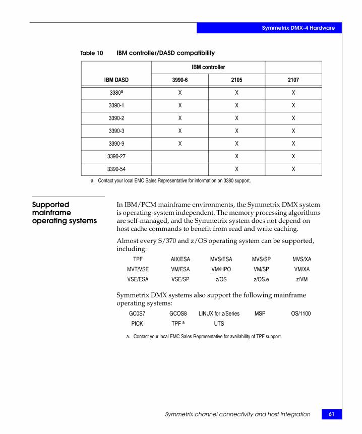
Symmetrix DMX-4 Hardware
Supported mainframe operating systems
In IBM/PCM mainframe environments, the Symmetrix DMX system is operating-system independent. The memory processing algorithms are self-managed, and the Symmetrix system does not depend on host cache commands to benefit from read and write caching.
Almost every S/370 and z/OS operating system can be supported, including:
Symmetrix DMX systems also support the following mainframe operating systems:
Table 10 IBM controller/DASD compatibility
❏ IBM controller ❏
IBM DASD 3990-6 2105 2107
3380a X X X
3390-1 X X X
3390-2 X X X
3390-3 X X X
3390-9 X X X
3390-27 X X
3390-54 X X
a. Contact your local EMC Sales Representative for information on 3380 support.
TPF AIX/ESA MVS/ESA MVS/SP MVS/XA
MVT/VSE VM/ESA VM/HPO VM/SP VM/XA
VSE/ESA VSE/SP z/OS z/OS.e z/VM
GC0S7 GCOS8 LINUX for z/Series MSP OS/1100
PICK TPF a
a. Contact your local EMC Sales Representative for availability of TPF support.
UTS
Symmetrix channel connectivity and host integration 61

62
Symmetrix DMX-4 Hardware
Fibre Channel disk subsystemThe Symmetrix DMX-4 disk subsystem are contained in the storage bays. They are fully redundant components and can be replaced nondisruptively. The disk subsystems consist of the following components:
◆ Disk drives — One-inch low-profile 4 Gb/s Fibre Channel disk drives available in 73 GB, 146 GB, 300 GB, 400 GB, and 450 GB sizes, 73 GB and 146 GB Flash drives, 500 GB and 1 TB SATA II disk drives.
◆ Two link control cards (Fibre Channel interface cards).
◆ Two power supply/cooling modules.
The drive enclosure supports 2 Gb/s or 4 Gb/s back-end fibre interface (FC-AL). The dual-loop configuration provides redundancy, port bypass capability, and disk access up to 4 Gb/s per loop. Flash drives are 2 Gb/s.
Disk drives The Symmetrix DMX-4 uses industry-standard 2 Gb/s and 4 Gb/s Fibre Channel disk drives for physical drives. The disk drives are installed in the front of storage bays and connect to a midplane. Each disk drive is integrated with a dual-port Fibre Channel Arbitrated Loop (FC-AL) controller with Fibre Channel interface that transports SCSI protocol. The Symmetrix DMX-4 supports Fibre Channel loops ranging from 15 drives to 60 drives per loop.
The DMX-4 series uses point-to-point connection to each drive in the drive enclosure. This allows access, diagnosis, and isolation of individual drives during corrective action. It also allows individual drives to be targeted for online testing during power up and replacement and when adding new capacity. The point-to-point drive connection capability enables more precise back-end fault recovery.
Table 11 on page 63 lists the features for each type of Symmetrix DMX-4 disk drive assembly.
EMC Symmetrix DMX-4 Product Guide

Symmetrix DMX-4 Hardware
SATA II drives The 500 GB and 1 TB 7.2K SATA II (Serial Advanced Technology Attachment) drives are a high-density option for tiered storage. SATA II drives and Fibre Channel drives can coexist in the same drive enclosure, but because of performance differences they should not be mixed in volume protection strategies. For example, SATA II and Fibre Channel drives should not be mixed together in the same RAID 5 group.
Table 11 Symmetrix DMX-4 disk drive features a
Disk capacity and rotational speed
Interface maximum data transfers per port b
Internal data rate megabits per second c
Average access time(read/write) ms Device level buffer
73 GB 10K / 15K rpm
2 / 4 Gb/s FC 470–944 / 685–1,142 4.7–5.4 / 3.5–4.0 16 MB
146 GB 10K / 15K rpm
2 / 4 Gb/s FCb 470–944 / 685–1,142 4.7–5.4 / 3.5–4.0 32 MB
300 GB 10K / 15K rpm
2 / 4 Gb/s FCb 470–944 / 864–1441 4.7–5.4 / 3.6–4.1 32 MB
400 GB10K rpm
2 / 4 Gb/s FC 725–1,211 3.9–4.2 16 MB
450 GB15K rpm
2 / 4 Gb/s FC 1.95 Gb/s (max) 3.4–4.1 16 MB
500 GB 7.2K rpm / SATA II
2 /4 Gb/s SATA II 470–944 8.5–9.5 32 MB
1 TB 7.2K rpm/SATA II
2 /4 Gb/s SATA II 1,070 (max) 8.2–9.2 32 MB
73 GBFlash drives
2 Gb/s FC Read 200 MB/secWrite 100 MB/sec
1mS N/A
146 GBFlash drives
2 Gb/s FC Read 200 MB/secWrite 100 MB/sec
1mS N/A
a. Contact your EMC Sales Representative for the latest drive specifications.
b. Auto-negotiates between 4-2 Gb/s.
c. These specifications are subject to change.
Fibre Channel disk subsystem 63

64
Symmetrix DMX-4 Hardware
Flash drives Flash drives provide maximum performance for latency sensitive applications. Flash drives, also referred to as solid state drives (SSD), contain no moving parts and appear as standard Fibre Channel drives to existing Symmetrix management tools, allowing administrators to manage Tier 0 without special processes or custom tools. Tier 0 Flash storage is ideally suited for applications with high transaction rates and those requiring the fastest possible retrieval and storage of data, such as currency exchange and electronic trading systems, realtime data feed processing, or mainframe transaction processing. A Symmetrix DMX-4 with Flash drives can deliver single-millisecond application response times and up to 30 times more IOPS than traditional 15,000 rpm Fibre Channel disk drives. Additionally, because there are no mechanical components, Flash drives require up to 98 percent less energy per IOPS than traditional disk drives.
Description Flash drives are currently available in 73 GB and 146 GB capacity and 2 Gb/s loop speed. Flash drives currently support RAID 1 (mirrored), RAID 10, RAID 5 (3+1), RAID 5 (7+1), RAID 6 (6+2), and RAID 6 (14+2) protection schemes.
Target usage Flash drives are best suited for low-latency applications in which the user requires consistent, low response times of less than 2 ms, for example; trading applications, transactional databases, and Exchange servers. Improvements will be seen in mixed workload environments, with the most improvements seen with higher cache read miss mixes.
Workload profiles that are high in random read miss, where read hit percentage is relatively low, will benefit greatly from Flash drives.
Write performance of Flash drives will also retain low latencies even on extremely high-write applications. This is possible through Symmetrix Enginuity and the existing high performance cache within the Symmetrix DMX-4 systems.
Note that Flash drives cannot help with reducing response time due to long distance replication. However, read misses still enjoy low response times.
Flash drives can be used as Clone source and target volumes. Flash drives can be used as SNAP source volumes. Virtual LUN Migration supports migrating volumes to and from Flash drives. Flash drives can be used with SRDF/A, SRDF/S, TF/Mirror, and Thin Pools.
Meta volumes can be configured on Flash drives as long as all of the logicals in the Meta group are on Flash drives.
EMC Symmetrix DMX-4 Product Guide

Symmetrix DMX-4 Hardware
Intermixing applications on Flash drives with applications on hard drives (HDDs) on a single back-end loop is allowed, but careful performance analysis of the specific applications is required beforehand to be sure that high HDD activity will not overcome benefits of Flash drives.
Packaging Flash drives are contained in the same type of 3.5 inch, low profile drive carriers as fibre channel drives. However, Flash drives use less energy than rotating media, and weigh less as well. When compared to a 73 GB rotating drive, the Flash drive uses 38% less energy on a per GB basis.
Configurationconsiderations
Due to the new nature of the technology, not all Symmetrix functions are currently supported on Flash drives. Some functions may be enabled in the future after further testing has been completed. The following is a list of the current limitations and restrictions of Flash drives:
◆ All members of a RAID 5 flash group must be configured on Flash drives.
◆ Quadrants that contain Flash drives need to be configured to operate at 2 Gb/s loop speed.
◆ Each DA slice requires four HDDs for Power Vault volumes (two on each loop). Internal volumes (Power Vault, Symmetrix File System, and Dynamic Relocation Volumes) cannot be configured on Flash drives.
Note: “Flash drive sparing rules” on page 211 contains additional information on Flash drives.
Link control cards The link control card’s (LCC) main function is to provide services to the drive enclosure, which includes the capability to control functionality and monitor environmental status. Each drive enclosure has two LCCs. The LCC performs the following functions:
◆ Individual Fibre Channel disk power on and poweroff functions◆ Failover control◆ Marker LED control◆ Individual disk port control◆ Drive presence detection◆ Reporting of temperature and voltage status information◆ RS-232 monitoring of the BBU modules
Note: “Fibre Channel arbitrated loop design” on page 165 contains additional information on the LCCs.
Fibre Channel disk subsystem 65

66
Symmetrix DMX-4 Hardware
Power supply/cooling module
Two power supply/cooling modules provide all necessary power and cooling to the 15 disk drives in the disk enclosure in an N+1 configuration.
Symmetrix DMX disk drive capacities
Precise storage capacity values depend on:
◆ Whether the user configures the disk to emulate an open systems device or a mainframe 3390 device.
◆ Whether the user calculates a gigabyte to equal:• 1,000 * 1,000 * 1,000 bytes• or 1,024 * 1,024 * 1,024 bytes
◆ The number of logical volumes configured on the disk.◆ Data protection option used: (RAID 1, RAID 5 (3+1), RAID 5
(7+1), RAID 6 (6+2), RAID 6 (14+2), RAID 10, SRDF).
Table 12 on page 67 shows the available Symmetrix cylinders and storage capacities for 73 GB, 146 GB, 300 GB, 400 GB, and 450 GB Fibre Channel drives, 73 GB and 146 GB Flash drives, and 500 GB, and 1 TB SATA II drives based on the mainframe, open systems, and iSeries emulations. The capacities are approximate because the number of logical volumes and data protection options are not factored into the total drive capacity.
EMC Symmetrix DMX-4 Product Guide

Symmetrix DMX-4 Hardware
The GB values shown in Table 12 on page 67 are based on the following conventions: The GB2 value is based on 1 GB = 1024 *1024 * 1024 bytes. The GB10 value is based on 1 GB = 1000 * 1000 * 1000 bytes. Although the open systems GB values are expressed differently, they are equivalent.
Table 12 Symmetrix DMX-4 disk drive capacitiesa
Disk size and speed (rpm) Raw capacity
Formatted capacity(open systems in GB10)
Formatted capacity(open systems in GB2)
Formatted capacity(mainframe systemsa
Formatted capacity (iSeries emulation)b
73 GB 10K or 15K c
73.41 GB 73.34 GB10 68.30 GB2 72.40 GB10 72.82 GB10
146 GB 10K or 15Kd
146.82 GB 146.69 GB10 136.62 GB2 144.81 GB10 145.66 GB10
300 GB 10K or 15K
300.0 GB 299.76 GB10 279.17 GB2 295.91 GB10 292.46 GB10
400 GB10K
400.0 GB 399.682 GB10 372.233 GB2 394.551 GB10 399.682 GB10
450 GB15K
450.00 GB 449.643 GB10 418.763 GB2 443.870 GB10 438.702 GB10
500 GB 7.2K SATA II
500.0 GB 499.605 GB10 465.293 GB2 493.19 GB10 N/A
1 TB7.2K SATA II
1000.0 GB 999.418 GB10 930.78 GB2 986.5810 N/A
a. Contact your local EMC Sales Representative for information on 3380 emulations, drives, and data protection methods.
b. 500 GB,1 TB SATA II drives, 73 GB and 146 GB Flash drives do not support iSeries emulations.
c. The drive capacities for the 73 GB Flash drives are the same as for the 73 GB FC drives.
d. The drive capacities for the 146 GB Flash drives are the same as for the 146 GB FC drives.
Fibre Channel disk subsystem 67
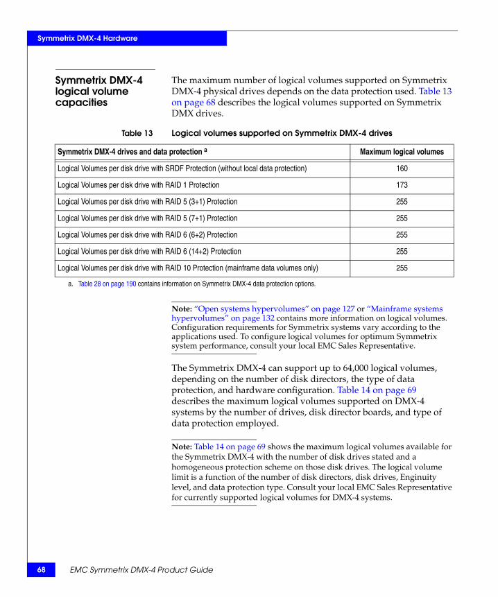
68
Symmetrix DMX-4 Hardware
Symmetrix DMX-4 logical volume capacities
The maximum number of logical volumes supported on Symmetrix DMX-4 physical drives depends on the data protection used. Table 13 on page 68 describes the logical volumes supported on Symmetrix DMX drives.
Note: “Open systems hypervolumes” on page 127 or “Mainframe systems hypervolumes” on page 132 contains more information on logical volumes. Configuration requirements for Symmetrix systems vary according to the applications used. To configure logical volumes for optimum Symmetrix system performance, consult your local EMC Sales Representative.
The Symmetrix DMX-4 can support up to 64,000 logical volumes, depending on the number of disk directors, the type of data protection, and hardware configuration. Table 14 on page 69 describes the maximum logical volumes supported on DMX-4 systems by the number of drives, disk director boards, and type of data protection employed.
Note: Table 14 on page 69 shows the maximum logical volumes available for the Symmetrix DMX-4 with the number of disk drives stated and a homogeneous protection scheme on those disk drives. The logical volume limit is a function of the number of disk directors, disk drives, Enginuity level, and data protection type. Consult your local EMC Sales Representative for currently supported logical volumes for DMX-4 systems.
Table 13 Logical volumes supported on Symmetrix DMX-4 drives
Symmetrix DMX-4 drives and data protection a Maximum logical volumes
Logical Volumes per disk drive with SRDF Protection (without local data protection) 160
Logical Volumes per disk drive with RAID 1 Protection 173
Logical Volumes per disk drive with RAID 5 (3+1) Protection 255
Logical Volumes per disk drive with RAID 5 (7+1) Protection 255
Logical Volumes per disk drive with RAID 6 (6+2) Protection 255
Logical Volumes per disk drive with RAID 6 (14+2) Protection 255
Logical Volumes per disk drive with RAID 10 Protection (mainframe data volumes only) 255
a. Table 28 on page 190 contains information on Symmetrix DMX-4 data protection options.
EMC Symmetrix DMX-4 Product Guide

Symmetrix DMX-4 Hardware
Table 14 Logical volumes supported for DMX-4 systems Maximum number
of disk drivesaNumber of DA
boards Data protection Maximum logical volumes per system
1,920 8 SRDF 64,000
1,920 8 RAID 1 64,000
1,920 8 RAID 5 (3+1) 64,000
1,920 8 RAID 5 (7+1) 32,768
1,920 8 RAID 6 (6+2) 30,720
1,920 8 RAID 6 (14+2) 15,360
1,920 8 RAID 10 16,000
1,440 6 SRDF 64,000
1,440 6 RAID 1 64,000
1,440 6 RAID 5 (3+1) 49,152
1,440 6 RAID 5 (7+1) 24,576
1,440 6 RAID 6 (6+2) 23,040
1,440 6 RAID 6 (14+2) 11,520
1,440 6 RAID 10 16,000
960 4 SRDF 64,000
960 4 RAID 1 64,000
960 4 RAID 5 (3+1) 32,768
960 4 RAID 5 (7+1) 16,384
960 4 RAID 6 (6+2) 15,360
960 4 RAID 6 (14+2) 7,680
960 4 RAID 10 16,000
240 2 SRDF 20,760
240 2 RAID 1 20,760
240 2 RAID 5 (3+1) 15,300
240 2 RAID 5 (7+1) 7,650
240 2 RAID 6 (6+2) 3,840
240 2 RAID 6 (14+2) 1,920
240 2 RAID 10 7,650
a. For information on 2,400 drive support, contact your EMC Sales Representative.
Fibre Channel disk subsystem 69

70
Symmetrix DMX-4 Hardware
Configuration rules for vault devices
Vault devices are volumes on designated physical disk drives that reserve a dedicated 5 GB space for vaulting data including metadata. The following configuration rules apply to the vaulting drives and disk directors:
◆ Each disk director pair requires 32 such dedicated devices for a total of 160 GB of vault space per disk director pair.
◆ The vault devices can only use single-mirror data protection and cannot be configured with TimeFinder/Snap, virtual, or dynamic spare devices.
◆ Vault drives are eligible for permanent sparing if there is a valid spare on the same port. The vault device cannot be moved to a different loop, but it can be moved to a different location on the same loop. “Permanent sparing” on page 212 contains additional information.
◆ The drive pool, virtual devices, or drive devices cannot reside in the 5 GB of vault space. However, they can reside on the same physical disk drive as the vault devices but not within the vault devices.
◆ The distribution of the vault devices across the disk directors, the back-end interfaces, and the physical disks should be such that a full vault will be possible within the time frame dictated by the capacity of the battery (up to five minutes).
◆ The total capacity of all of the vault hypervolumes in the system will be at least sufficient to keep two logical copies of the persistent part of global memory.
◆ Flash drives cannot be used as vault devices.
Symmetrix DMX disk drive emulations
Symmetrix DMX systems support connectivity to mainframe systems and open systems hosts. When the Symmetrix DMX systems are configured to open systems hosts such as UNIX, Windows, Linux, or iSeries the Symmetrix drives emulate standard drives. When the Symmetrix DMX systems are configured to IBM z/OS/PCM system hosts, the Symmetrix drives emulate IBM CKD DASD.
Note: The Symmetrix Enterprise Storage Platform (ESP) software enabler, a software option, is required if you plan to store and access mainframe and open systems data on the same Symmetrix system.
EMC Symmetrix DMX-4 Product Guide

Symmetrix DMX-4 Hardware
Deleting (and then adding) devices online
Enginuity supports removing and then adding devices online, which facilitates the following configuration enhancements:
◆ Change Device Emulation Online — Remove a CKD volume and add an FBA volume.
◆ Convert between mirrored and RAID protected volumes.
◆ The optimal order is to delete devices and then add. If done in the reverse order, unnecessary global memory will be allocated for the deleted devices.
◆ When attempting to add or delete devices, or change protection type of devices, a new minimum cache value will be calculated. In rare cases this new value could prohibit the changes until additional memory is added to the system.
Open system disk emulation
On open systems hosts, the Symmetrix DMX logical disk volumes appear as standard SCSI drives with data stored in Fixed Block Architecture (FBA) format. All host logical volume manager software can be used with Symmetrix disk volumes. The following paragraphs describe the FBA disk format and logical volume structure.
FBA data andcommand format
Fixed Block Architecture (FBA) drives store data in fixed-sized blocks (typically 512 bytes). A disk drive using FBA format is viewed as a large array of blocks. The physical position of each block (cylinder and track) is usually not significant to the host. When requesting disk access for read or write, the host addresses a file by the logical block address (LBA) of the starting block and a count of the total blocks used by the file. Symmetrix channel directors and disk directors control access to global memory and drives, responding to host requests as a standard disk drive.
Note: Drives in Symmetrix DMX systems attached to iSeries hosts are configured in 520-byte blocks.
Logical volumestructure (open
systems)
The channel directors interact with global memory. Therefore, there is no physical meaning to cylinders, tracks, and heads on the Symmetrix logical volume from the front-end point of view. However, Symmetrix systems use a logical geometry definition for their logical volume structure. This geometry is reflected in the mode sense data available to the host.
Fibre Channel disk subsystem 71

72
Symmetrix DMX-4 Hardware
Symmetrix systems use the following logical volume structure:
◆ Each logical volume has n cylinders◆ Each cylinder has 15 tracks (heads)◆ Each track has 128 blocks of 512 bytes
Therefore, a Symmetrix logical volume with n cylinders has a usable block capacity of:
n * 15 * 128
n for each volume is defined during Symmetrix configuration.
To calculate the size of the logical volume:
Number of cylinders * heads * blocks * 512(n * 15 * 128* 512)
Note: “Open systems hypervolumes” on page 127 provides information on configuring open systems logical volumes.
Flexible devicegeometry
(for Sun Solaris hosts)
Flexible device geometry improves interoperability when migrating data between DMX-3 or DMX-4 and older Symmetrix systems. When the Symmetrix DMX-3 was introduced, the disk geometry presented to the host by the disk array changed. The number of sectors per track was doubled to 128, which also led to a doubling of the cylinder size. In the Sun Solaris operating system, disk geometry, disk size, manufacturer ID, and the partition table are stored in the label in sector 0 of the disk. The label is written to the disk using the format utility, which makes a device usable to the OS. When a Solaris device is opened for I/O activity, the label is written to host cache and the SCSI driver uses the partition information to translate relative partition addresses to device absolute logical block addresses.
The difference between disk geometries will not cause issues in most scenarios. However, there are three pieces of information contained in the disk label that, if modified, can cause a new label to be written by the operating system. If disk geometry, manufacturer ID, or the size of the disk drive change, format will write a new label if “auto configure” is run from the format> type menu, followed by label.
When a device is migrated to a DMX-4 or DMX-3 using a product that produces a track-by-track copy of the source device on the target device (SRDF, RecoverPoint, or Open Replicator for example), the entire device is migrated including the VTOC label. When this occurs between devices with heterogeneous disk geometries, there will be a difference between the disk geometry written in the label on the target (which was copied from the source) and the disk geometry that is presented to the target host by the DMX-4 or DMX-3.
EMC Symmetrix DMX-4 Product Guide

Symmetrix DMX-4 Hardware
If the device is re-labeled, there may be potential issues with data availability. This is because Solaris reserves two cylinders from every device for use by the operating system. DMX-4 and DMX-3 cylinders are twice as large as cylinders from previous generation Symmetrix disk arrays, meaning that the operating system will overwrite the last 1920 sectors of the user data area with an area reserved for operating system use.
It should be noted that, regardless of a difference in geometry between the label and the actual disk, no issue will be seen if the disk is not re-labeled by the user. This potential issue has been resolved with the introduction of Flexible Device Geometry.
To alleviate any potential for corruption, two features have been added to Symmetrix Enginuity. A bin file setting has been included that allows the DMX-3 and DMX-4 to present an external device geometry for all Symmetrix devices that is identical to the device geometry of earlier Symmetrix arrays. Functionality has also been added to Enginuity that allows alternate disk geometry to be presented on a device by device basis.
Note: Contact your EMC Customer Engineer to determine if this feature should be enabled on your Symmetrix DMX system.
IBM CKD DASD disk emulation
The Symmetrix DMX system appears to mainframe operating systems as a 3990-6, 2105, or 2107 controller. The physical drives can appear to the mainframe operating system as a mix of multiple 3390 and 3380 device types. All standard models of the 3380 or 3390 volumes can be emulated up to the physical volume sizes installed.
A single Symmetrix system can simultaneously support both 3380 and 3390 device emulations. Table 15 on page 74 lists the Symmetrix characteristics for some standard IBM device emulation modes. Symmetrix systems also support nonstandard device sizes, as long as the cylinder count does not exceed that of the equivalent IBM device type. Appendix A, “Symmetrix DMX-4 Specifications,”contains more IBM DASD emulation characteristics.
Note: Contact your EMC Sales Representative for 3380 support.
Fibre Channel disk subsystem 73

74
Symmetrix DMX-4 Hardware
Mixed trackgeometries
You can configure a Symmetrix DMX system with both 3380 and 3390 track geometries on the same disk devices (3380 and 3390 devices cannot be defined in the same SSID or LCU). A single disk device can contain up to 255 logical volumes, depending on the data protection used.
Note: “Mainframe systems hypervolumes” on page 132 contains information on configuring mainframe logical volumes.
IBM/PCM data andcommand formats
All Symmetrix systems support the count-key-data (CKD) and extended count-key-data (ECKD) format used by IBM 3390 and 3380 DASD. IBM 3390 Storage Control Reference contains a full description of the channel command words (CCW) supported. Figure 12 on page 74 shows the CKD track format emulated for 3390 and 3380 DASD.
Figure 12 Track format for 3390 DASD
Table 15 IBM DASD emulation characteristics
IBM DASD model MB/volume Bytes/track Bytes/cylinder Cylinders/volume
3390-54a 55,688 56,664 849,960 65,520
3390-27 27,844 56,664 849,960 32,760
3390-9 8,514 56,664 849,960 10,017
3390-3 2,838 56,664 849,960 3,339
3390-2 1,892 56,664 849,960 2,226
3390-1 946 56,664 849,960 1,113
3380Ka 1,891 47,476 712,140 2,655
a. Contact your local EMC Sales Representative for currently supported IBM Controller/DASD emulation modes and 3380 support.
Indexmarker
HA D
R1
KCDMagneticdisk
KC
R0
Indexmarker
EMC Symmetrix DMX-4 Product Guide

Symmetrix DMX-4 Hardware
Track format All tracks are written with formatted records. The start and end of each track are defined by the index marker. Each track has the same basic format as that shown in Figure 12 on page 74. That is, it has an index marker, home address (HA), record zero (R0), and one or more data records (R1 through Rn). These track formats are discussed in the following sections.
Information is recorded on all Symmetrix drives in an emulation format chosen at configuration. Each track contains certain nondata information (such as the address of the track, the address of each record, the length of each record, and the gaps between each area), and data information.
Index marker — An index marker indicates the physical beginning and end of each track for each disk drive (Figure 12 on page 74).
Home address (HA) — There is one home address on each track that defines the physical location of the track by specifying the track address (cylinder and head location) and the condition of the track (flag byte). The flag byte indicates whether the track is usable, defective, or an alternate track.
Record zero–r0 (track descriptor record) — This is the first record after the home address. The Count field indicates its physical location (cylinder and head), record number, key length, and data length. In general, the key length is zero bytes and the data length is eight.
Data records (R1 through Rn) — All remaining records on a track are data records. The Count field indicates the data record's physical location (cylinder and head), record number, key length, and data length. The key is optional and, when used, contains information used by an application. The data area contains the user data. To determine the number of records a track can hold, refer to the IBM 3390 Direct Access Storage Introduction or IBM 3380 Direct Access Storage Introduction for the equations for calculating this number.
Track capacity Track capacity is the maximum capacity achievable when there is one physical data record per track formatted without a key. Because the track can contain multiple data records, additional Address Markers, Count Areas, and gaps reduce the number of bytes available for data.
The track capacity is the number of bytes left for data records after subtracting the bytes needed for the home address, record zero, address marker, count area, cyclic check (for error correction), and the gaps for one data record.
For 3390 emulations, the track capacity is 56,664 bytes. For 3380 emulations, the track capacity is 47,476 bytes.
Fibre Channel disk subsystem 75

76
Symmetrix DMX-4 Hardware
EMC Symmetrix DMX-4 Product Guide
Channel, disk, and global memory directorsThis section describes the Symmetrix DMX-4 directors. The channel directors and global memory directors manage the storage control functions. The disk directors handle the data storage functions.
Channel director connectivity
The Symmetrix DMX-4 provides channel connectivity through combinations of mainframe systems and open systems channel directors. These include:
◆ Fibre Channel directors (also used with SRDF)◆ ESCON directors◆ ESCON directors used for SRDF, data migration, and the SDMS™
(Symmetrix Data Migration Service) application◆ Multiprotocol Channel Directors (MPCD) available with these
channel connection combinations:• Fibre Channel• FICON • iSCSI• GigE (Gigabit Ethernet) remote directors used for SRDF• GigE IPv4/v6 (IPsec capable) directors
Note: The Symmetrix DMX-4 supports mixed ESCON, FICON, Fibre Channel, and iSCSI interfaces when the required Symmetrix ESP software is installed on the Symmetrix system. Contact your local EMC Sales Representative for currently supported host connectivity.
The Symmetrix DMX-4 supports open systems hosts such as UNIX systems, Linux systems, and Windows connectivity through Symmetrix Fibre Channel or iSCSI directors. (iSeries connectivity is only supported through Fibre Channel directors.) The Symmetrix DMX-4 supports mainframe connectivity through ESCON and FICON directors. The Symmetrix DMX-4 connects directly to host processors through physical channel attachments. Table 16 on page 77 describes the protocols that are supported by the Symmetrix DMX-4 channel directors.

Symmetrix DMX-4 Hardware
Channel director descriptions
Symmetrix DMX-4 channel directors are single boards that occupy one slot on the Symmetrix midplane. All channel directors interface to host channels through interface adapter cards connected to the opposite side of the midplane. The Symmetrix DMX-4 supports up to 12 channel directors.
Note: Appendix C, “Planning and Installation,”provides information on mainframe and open systems channel director configurations. Contact your local EMC Sales Representative for specific supported configurations.
All channel directors contain four high performance processor complexes. The channel directors process data from the host and manage access to global memory over a direct matrix (DMX) technology (Figure 8 on page 54). Each channel director on the Symmetrix DMX-4 supports eight internal links to global memory. DMX technology is used across the Symmetrix system, as it is also designed into each global memory director. In addition to DMX technology, each director includes support for a separate message matrix for the transfer of control information.
Note: “DMX-4 point-to-point message matrix” on page 55 and “DMX-4 communications and environmental control” on page 90 provide information on the Symmetrix DMX message matrix.
Table 17 on page 78 describes the DMX-4 channel director models.
Table 16 Supported protocols and Symmetrix DMX-4 channel directors
Protocol a Usable system ports b Ports per channel director
4 Gb/s Fibre Channel host/SAN ports 2-64 1-8 per Fibre Channel Director
4 Gb/s Fibre Channel remote replication ports 2-8 1-4 per Fibre Channel Director
1 Gb/s iSCSI ports 2-32 1-4 per Multiprotocol Channel Director
1 Gb/s GigE remote replication ports 2-8 1-4 per Multiprotocol Channel Director
1 Gb/s GigE IPv4/v6 (IPsec capable) 2-8 1-4 per Multiprotocol Channel Director
4 Gb/s FICON host ports 2-32 1-4 per Multiprotocol Channel Director
ESCON host ports 2-80 1-8 per ESCON Channel Director
ESCON remote replication ports 2-8 1-4 per ESCON Channel Director
a. Contact your local EMC Sales Representative for ESCON channel director and GigE Remote support availability.b. Usable ports are per qualified channel directors.
Channel, disk, and global memory directors 77

78
Symmetrix DMX-4 Hardware
EMC Symmetrix DMX-4 Product Guide
Fibre Channel directors front-end
The Fibre Channel front-end director has eight FC ANSI compliant, 4 Gb/s (also configurable to 2 Gb/s, and 1 Gb/s) Fibre Channel interfaces for connection to host systems. The director has eight high-speed paths to global memory. The Fibre Channel director interfaces to the host channels through an eight-port Fibre Channel interface adapter and is available in single-mode and multimode configurations (Table 17 on page 78). Each Symmetrix DMX Fibre Channel director supports eight internal links to global memory. Data transfers between host and global memory can execute concurrently across all Fibre Channel ports on a director. Table 18 on page 79 lists the Fibre Channel front-end support capabilities for directors, their Symmetrix devices, and their addressing.
Table 17 Symmetrix DMX-4 channel director models and descriptions
Model number Description aFC b GigE FICON
MM SM MM MM SM
DMX4-80000B 8-port Fibre Channel (FC) Director (8 MM ports) 8 0 0 0 0
DMX4-71000B 8-port Fibre Channel Director (7 MM / 1 SM port) 7 1 0 0 0
DMX4-62000B 8-port Fibre Channel Director (6 MM / 2 SM ports 6 2 0 0 0
DMX4-08000B 8-port Fibre Channel Director (8 SM ports) 0 8 0 0 0
DMX4-00004B 4-port FICON Channel Director (4 SM ports) 0 0 0 0 4
DMX4-00040B 4-port FICON Channel Director (4 MM ports) 0 0 0 4 0
DMX4-00103B 4-port MPCDc (1 GigE or iSCSI MM port / 3 FICON SM ports) 0 0 1 0 3
DMX4-00400 4-port GigE or iSCSI Channel Director (4 MM ports) 0 0 4 0 0
DMX4-ESCD8 8-port ESCON DIR (8 MM ports) N/A N/A N/A N/A N/A
DMX4-40002B 6-port MPCD (4 FC MM ports / 2 FICON SM ports) 4 0 0 0 2
DMX4-40200B 6-port MPCD (4 FC MM ports / 2 GigE or iSCSI MM ports) 4 0 2 0 0
DMX4-60100B 7-port MPCD (6 FC MM ports / 1 GigE or iSCSI MM port) 6 0 1 0 0
DMX4-00103BS 4-port MPCD (1 GigE IPv4/v6 (IPsec capable) MM port/ 3 FICON SM ports)
0 0 1 0 3
DMX4-00400S 4-port GigE or iSCSI Channel Director (4 GigE IPv4/v6 (IPsec capable) MM ports)
0 0 4 0 0
DMX4-40200BS 6-port MPCD (4 FC MM ports/ 2 GigE IPv4/v6 (IPsec capable) MM ports)
4 0 2 0 0
DMX4-60100BS 7-port MPCD (6 FC MM ports/ 1 GigE IPv4/v6 (IPsec capable) MM port)
6 0 1 0 0
a. Contact your local EMC Sales Representative for currently supported host channel directors and GigE remote directors.
b. FC = Fibre Channel, MM = Multimode, SM = Single-mode.
c. MPCD = Multiprotocol Channel Director.

Symmetrix DMX-4 Hardware
Note: The numerical values for Symmetrix devices stated in Table 18 on page 79 are the maximum allowed according to the architectural limits of the microcode running on the Fibre Channel front-end director. The actual limits allowed for customer environments will be lower and are dependent on the host type, HBA and driver type/version, and overall system implementation. Also, note that using metadevices will reduce the number of host-visible volumes for a given number of devices (Symmetrix Devices) configured to the Fibre Channel front-end director; that is, each member of the metadevice will be counted to the allowed limit of devices configured to a Fibre Channel front-end director. For information on Fibre Channel host attachments, go to the EMC Powerlink website.
The Symmetrix DMX-4 can support up to eight qualified Fibre Channel directors. Contact your local EMC Sales Representative for specific supported configurations.
Fibre Channel adapters front-end
The Symmetrix DMX-4 Fibre Channel adapters provide the connectivity between the host channels and the Fibre Channel front-end director through optical transceiver connections.
Note: Symmetrix Fibre Channel directors currently support connections to a number of hosts supporting Fibre Channel connectivity. For a current list of supported hosts, go to the EMC Powerlink website.
Fibre Channeldirectors for SRDF
The Fibre Channel host director can be Enginuity-configured as the link between Symmetrix units in a Symmetrix Remote Data Facility (SRDF) configuration. The Fibre Channel director interfaces to Symmetrix channels through the Fibre Channel interface adapter.
iSeries Fibre Channelconnectivity
The Symmetrix Fibre Channel adapters, through fiber, connect to the iSeries 270 and 8xx models. When using directly connected fiber devices (point-to-point) the maximum distance is 500 meters in 1 Gb/s mode.
Table 18 Symmetrix devices and addressing capabilitiesfor Fibre Channel front-end directors
Maximum Symmetrix devices and device addressesMaximum Symmetrix devices per front-end
Fibre Channel processor complex
Symmetrix Devices per Processor Complex 4,096
Symmetrix Devices per Fibre Channel Director 16,384
Addresses Range per Port 0–4,095 (0x000–0xFFF)
Channel, disk, and global memory directors 79
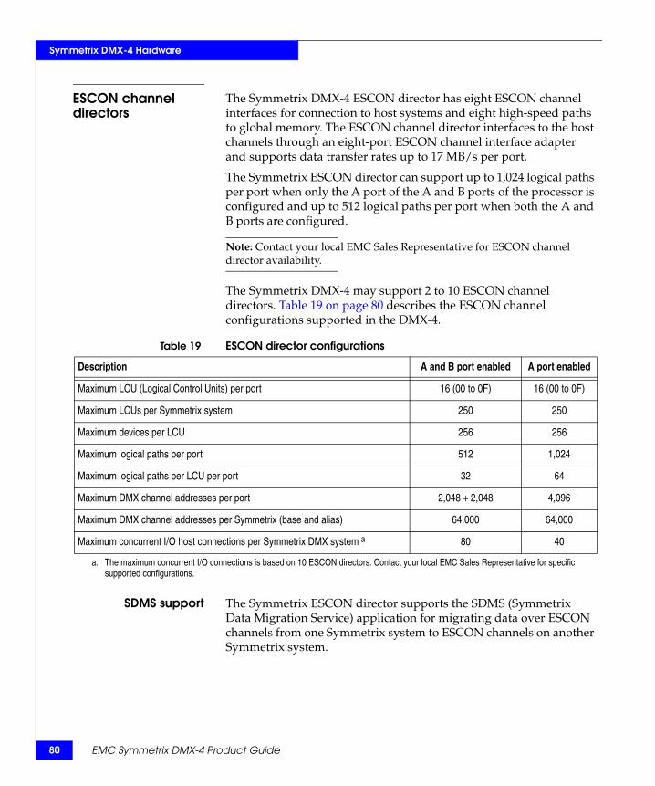
80
Symmetrix DMX-4 Hardware
ESCON channel directors
The Symmetrix DMX-4 ESCON director has eight ESCON channel interfaces for connection to host systems and eight high-speed paths to global memory. The ESCON channel director interfaces to the host channels through an eight-port ESCON channel interface adapter and supports data transfer rates up to 17 MB/s per port.
The Symmetrix ESCON director can support up to 1,024 logical paths per port when only the A port of the A and B ports of the processor is configured and up to 512 logical paths per port when both the A and B ports are configured.
Note: Contact your local EMC Sales Representative for ESCON channel director availability.
The Symmetrix DMX-4 may support 2 to 10 ESCON channel directors. Table 19 on page 80 describes the ESCON channel configurations supported in the DMX-4.
SDMS support The Symmetrix ESCON director supports the SDMS (Symmetrix Data Migration Service) application for migrating data over ESCON channels from one Symmetrix system to ESCON channels on another Symmetrix system.
Table 19 ESCON director configurations
Description A and B port enabled A port enabled
Maximum LCU (Logical Control Units) per port 16 (00 to 0F) 16 (00 to 0F)
Maximum LCUs per Symmetrix system 250 250
Maximum devices per LCU 256 256
Maximum logical paths per port 512 1,024
Maximum logical paths per LCU per port 32 64
Maximum DMX channel addresses per port 2,048 + 2,048 4,096
Maximum DMX channel addresses per Symmetrix (base and alias) 64,000 64,000
Maximum concurrent I/O host connections per Symmetrix DMX system a 80 40
a. The maximum concurrent I/O connections is based on 10 ESCON directors. Contact your local EMC Sales Representative for specific supported configurations.
EMC Symmetrix DMX-4 Product Guide

Symmetrix DMX-4 Hardware
Multiprotocol Channel Directors
The Symmetrix DMX-4 Multiprotocol Channel Director (MPCD), through mezzanine card technology, supports Fibre Channel, GigE, GigE IPv4/v6 (IPsec capable), iSCSI, and FICON protocols on Symmetrix DMX systems.
The MPCD implements a flexible mezzanine card that delivers highly configurable support for FICON channels to mainframe systems, Fibre Channel connections to open systems configurations, or Gigabit Ethernet support for iSCSI, or SRDF over IP connections.
Note: Contact your local EMC Sales Representative for currently supported protocols. Table 17 on page 78 describes the supported Multiprotocol models.
FICON channel director
FICON channel directors support native mode point-to-point connections and FICON native mode switched point-to-point connections to IBM 9672, G5/G6, z/900, and z/990 systems running z/OS, z/VM, VM/ESA, and VSE/ESA operating systems. FICON employs ESCON protocols that have been mapped to the FC-4 upper-level protocol layer of the Fibre Channel architecture. FICON supports multiple concurrent I/O connections, channel program multiplexing, and better link utilization than ESCON path switching. FICON allows the consolidation of multiple ESCON channels into one FICON channel.
The FICON mezzanine card provides one single-mode or multimode LC bidirectional (full duplex) connection. Symmetrix FICON channels transfer data at speeds up to 4 Gb/s.
Note: “Symmetrix FICON configurations” on page 95 contains information on additional configuration options.
The Symmetrix DMX FICON design auto-detects 4 Gb/s, 2 Gb/s, or 1 Gb/s at switch or channel port login time.
Channel, disk, and global memory directors 81

82
Symmetrix DMX-4 Hardware
The Symmetrix DMX-4 system may support up to eight FICON channel directors. Table 20 on page 82 describes the FICON channel director configurations supported in the DMX-4.
Gigabit Ethernet (GigE) remote directors
GigE remote mezzanine cards on the MPCD enable remote director functionality based upon Gigabit Ethernet technology that enable direct Symmetrix-to-IP network attachment and eliminate the need for expensive media converter appliances.
GigE support for SRDF on Symmetrix DMX systems:
◆ Increases the options for Symmetrix-to-Symmetrix connectivity.
◆ Allows the Symmetrix system to connect to your existing Ethernet infrastructure and directly access high-speed data transmission conduits using Internet Protocol (IP).
◆ Supports SRDF traffic to one or more remote Symmetrix systems that also have GigE remote directors installed.
◆ Supports TCP/IP protocols and function layers.
◆ Is fully compatible with the SRDF protocols and other Symmetrix DMX directors, drives, software, and protection schemes.
Symmetrix DMX GigE remote channels for SRDF transfer data at speeds up to 1 Gb/s. The GigE director provides up to four 1 Gb/s Ethernet ports and connects using LC connectors.
Table 20 FICON director configurations
Maximum LCUs (Logical Control Units) per port 64 (00 to FE)
Maximum LCUs per Symmetrix system 250
Maximum devices per LCU 256
Maximum logical paths per port 8,192
Maximum logical paths per LCU per port 128
Maximum DMX channel addresses per port 16,382
Maximum DMX channel addresses per Symmetrix (base and alias) 64,000
Maximum I/O host connections per Symmetrix DMX system a 32
a. The maximum I/O connections are based on 8 FICON directors for the DMX-4. Contact your local EMC Sales Representative for specific supported configurations.
EMC Symmetrix DMX-4 Product Guide
Symmetrix DMX-4 Hardware
GigE IPv4/v6 (IPsec capable) channel director
The GigE IPv4/v6 (IPsec capable) channel director provides support for the latest Internet Protocol standards, including IPsec (Internet Protocol Security) and IPv6. The embedded line-grade encryption co-processor provides strong security without degrading performance. Preshared encryption keys simplify management while maintaining security for data in transit.
These directors can co-exist in the same system with any existing DMX-4 channel directors. With the new director, IPsec can be enabled on a port-by-port basis. IPsec is enabled through a separately purchased software license.
The IP Stack version can be similarly configured per port. No additional software license is required.
The number of IPsec sessions will be limited to 100 per port. IPsec can be enabled for SRDF connections. IPsec enabled and IPsec disabled channel directors can co-exist in the same Symmetrix.
“IPsec security features” on page 187 contains additional information on IPsec.
iSCSI channel directors
The Symmetrix DMX-4 MPCD, through mezzanine card technology, supports iSCSI channel connectivity by way of Gigabit Ethernet (GigE) hardware for the Symmetrix DMX systems. The iSCSI channel director supports iSCSI channel connectivity to IP networks and to iSCSI-capable open systems server systems for block storage transfer between hosts and storage. The primary applications are storage consolidation and host extension for stranded servers and departmental workgroups. Symmetrix GigE remote channels for SRDF transfer data at speeds up to 1 Gb/s. The Symmetrix iSCSI director provides up to four 1Gb/s Ethernet ports and connects using LC connectors.
The iSCSI directors support the iSNS protocol, a mechanism that provides Naming and Discovery services for iSCSI initiators. The iSNS server information is configured in the Symmetrix IMPL file for each iSCSI director. Each iSCSI director must register itself with the iSNS server, which provides:
◆ A mechanism to query iSNS server to find other hosts/targets.◆ Support for State Change Notification and Status Inquiry.
The iSCSI director supports TCP/IP protocols and function layers. It is fully compatible with the SRDF protocols and other Symmetrix DMX directors, drives, software, and protection schemes.
Channel, disk, and global memory directors 83

84
Symmetrix DMX-4 Hardware
EMC Symmetrix DMX-4 Product Guide
Fibre Channel disk directors back-end
The Symmetrix DMX-4 Fibre Channel back-end disk directors manage the interface to the disk drives, and are responsible for data movement between the disk drives and global memory. Each disk director on a Symmetrix DMX system supports eight internal links to global memory.
The Symmetrix DMX-4 features a 4 Gb/s Fibre Channel back-end infrastructure. The Fibre Channel disk director has eight multiplex processors that support one port each on its back adapter.
The Symmetrix DMX-4 is available with two, four, six, or eight disk directors, supporting Fibre Channel loops ranging from 15 drives to 60 drives per loop.
Note: “Symmetrix DMX-4 logical volume capacities” on page 68 contains information on maximum logical volumes supported on each Symmetrix DMX physical disk drive and the maximum logical volumes supported for each Symmetrix DMX model.
Global memory directors
The Symmetrix DMX-4 global memory director technology is one of the most crucial components of a Symmetrix system. The DMX-4 uses global memory directors that use industry-standard Double Data Rate Synchronous Dynamic Random-Access Memory (DDR SDRAM), the latest generation of DDR SDRAM chip technology.
All read and write operations transfer data to or from global memory. Any transfers between the host processor, channel directors, and global memory directors are achieved at much greater electronic speeds than transfers involving disks. The DMX-4 global memory directors work in pairs. The hardware writes to the primary global memory director first, and then automatically writes data to the secondary global memory director. All reads are from the primary memory director. Upon a primary or secondary global memory director failure, all directors drop the failed global memory director and switch to a nondual write mode. Striping between global memory directors is default.
Each Symmetrix DMX-4 global memory director accommodates four separately addressable, simultaneously accessible memory regions, which greatly reduces the probability of contention for global memory access.

Symmetrix DMX-4 Hardware
Each global memory director has 16 ports with point-to-point serial connections between the global memory director and channel or disk directors (16 directors) through the direct matrix. Each memory director port consists of a pair of full-duplex serial links—two serial links out (TX) and two serial links in (RX).
Each of the eight director ports on the 16 directors connect to one of the 16 memory ports on each of the eight global memory directors (Figure 13 on page 85). These 128 individual point-to-point connections facilitate up to 128 concurrent cache operations in the system.
Figure 13 Global memory director to channel and disk director matrix
The DMX architecture ensures highest performance due to the following:
◆ Requests for global memory are expedited to reduce locking.
◆ Requests are intelligently arbitrated to optimize available resource usage.
Dir 3
Dir 4
Dir 7
Dir 8
Dir 9
Dir 10
Dir 14
Dir 13
Dir 1
Dir 2
Dir 5
Dir 6
Dir 11
Dir 12
Dir 15
Dir 16
M 0
M 1
M 2
M 3
M 4
M 5
M 6
M 7
Channel, disk, and global memory directors 85
86
Symmetrix DMX-4 Hardware
Global memory director configuration
The Symmetrix DMX system can support up to eight slots in the midplane dedicated to global memory and 512 GB of global memory (256 GB effective) global memory. Individual global memory directors are available in 8 GB, 16 GB, 32 GB, and 64 GB sizes.
When configuring global memory for the Symmetrix DMX systems follow these guidelines:
◆ Very large eight disk director configurations may be limited or restricted by currently available Symmetrix DMX-4 maximum memory.
◆ Global memory directors can be added to the DMX-4 not to exceed the maximum designed for the system’s configuration.
◆ Global memory directors must be configured in pairs of the same capacity.
EMC Symmetrix DMX-4 Product Guide
Symmetrix DMX-4 Hardware
Symmetrix DMX-4 power subsystemsThe Symmetrix DMX-4 power subsystem uses a 2N power architecture. The Symmetrix DMX-4 power subsystem includes the following features in the system bay and storage bay:
◆ 2N power zones
◆ Dual-line cords, one for each zone per bay, providing on/off function
◆ BBU modules with internal chargers and electronic status reporting
The DMX-4 power subsystem architecture provides two completely separate power zones (Power Zone A and Power Zone B), each of which can maintain power for an entire system bay or storage bay independent of the operation of the second zone. There is no redundancy within each zone, rather the redundancy is accomplished through the two-zone design.
System bay power subsystem components
The system bay contains up to eight power supplies that are split into two power zones—Power Zone A and Power Zone B, consisting of up to four power supplies each. The system bay also contains up to eight Battery Backup Unit (BBU) modules providing battery backup in the event an AC failure occurs. One BBU provides the AC line power, and high voltage DC backup to one power supply. The A side BBU modules receive their power from the A side Power Distribution Unit (PDU) and the B side BBU modules receive their power from the B side PDU (Figure 14 on page 89). Two Power Distribution Panels (PDPs), one for each zone, provide a centralized cabinet interface and distribution control of the AC power input lines when connected to the system bay PDUs. The PDPs contain the manual On/Off power switches, which are accessible through the rear door. The DMX-4 system bay PDPs are available in three-phase Delta and three-phase WYE configurations.
Through an RS-232 interface, the XCM modules communicate with the system bay BBU modules to determine the BBU status and run battery tests.
Symmetrix DMX-4 power subsystems 87

88
Symmetrix DMX-4 Hardware
Storage bay power subsystem components
The storage bay power subsystem consists of the drive enclosure power supply/ cooling modules and the BBU modules that provide the battery backup for the drive enclosures. The A side BBU modules receive their power from the A side PDU and support both the A and B side drive enclosures. The B side BBU modules receive their power from the B side PDU (Figure 14 on page 89) and support both the A and B side drive enclosures. Two PDPs, one for each zone, provide a centralized cabinet interface and distribution control of the AC power input lines when connected to the storage bay PDUs. The storage bay PDPs contain the manual On/Off power switches, which are accessible through the rear door. The DMX-4 storage bay PDPs are available in three-phase Delta and three-phase WYE configurations.
Symmetrix DMX-4power configurations
The Symmetrix DMX-4 power subsystem supports three-phase Delta or three-phase WYE configurations. Each bay requires two separate PDUs—one for Zone A and one for Zone B power for the Symmetrix DMX-4 system bay and each storage bay (Figure 14 on page 89).
Note: “Power and cooling data” on page 269, “Electrical specifications and power requirements” on page 270, and “Symmetrix DMX-4 power requirements” on page 290 contain more detailed information on the Symmetrix DMX-4 power requirements. The EMC Symmetrix DMX-4 Physical Planning Guide available on the EMC Powerlink website provides additional information.
EMC Symmetrix DMX-4 Product Guide

Symmetrix DMX-4 Hardware
Figure 14 Symmetrix DMX-4 system bay and storage bay to customer PDU power cabling
Zone B AC inputcable B
Cable connectors are shown asthey exit the bottom rear of the
DMX-4 bays.
This cabling is internalto the DMX-4 bays.
The customer’s AC power feeds are connected to these two
three-phase connectors.
Customer’s powerdistribution unit
number B
DMX-4 system bayrear view
Zone A AC inputcable A
Zone B PDP (Left)
Zone A PDP (Right)
Zone B AC inputcable B
Cable connectors are shown asthey exit the bottom rear of the
DMX-4 bays.
This cabling is internalto the DMX-4 bays.
The customer’s AC power feeds are connected to these two
three-phase connectors.
DMX-4 storage bayrear view
Zone A AC inputcable A
Zone B PDP (Left)
Zone A PDP (Right)
15 ftExtension cord
15 ftExtension cord
15 ftExtension cord
15 ftExtetsion cord
Customer’s powerdistribution unit
number A
Customer’s powerdistribution unit
number B
Customer’s powerdistribution unit
number A
Symmetrix DMX-4 power subsystems 89

90
Symmetrix DMX-4 Hardware
EMC Symmetrix DMX-4 Product Guide
DMX-4 communications and environmental controlWithin the Symmetrix DMX-4 message matrix are the Environmental Control Module (ECM) and Communication Control Module (CCM). These two modules provide the low-level system-wide communications for running application software, monitoring, and system diagnostics from the service processor.
Communications control functions
The XCM’s primary function is to act as a communications agent between the service processor (KVM and server) and the embedded processing nodes within the system. Figure 15 on page 91 illustrates the Ethernet fabric interconnecting the processing nodes to the service processor. External connections to the service processor provide dial-home capabilities for remote monitoring and diagnostics.
The software-driven failover mechanism exists such that the Ethernet fabric remains intact should an XCM become temporarily unavailable. As a backup to the Ethernet fabric, the XCM also contains RS-232 multiplexing logic to allow for an alternate means of serial communication to embedded processing nodes within the DMX-4. The XCM also has the ability to issue remote commands to the director boards, global memory directors, and itself. These commands can be issued from the service processor or remotely, by the EMC Customer Support Center, providing a rich set of intelligent serviceability functions. Also within the XCM is the top-level fabric for the message matrix communications system. This is a high-speed communications fabric within the DMX-4 that allows for fast, reliable messaging between compute nodes.
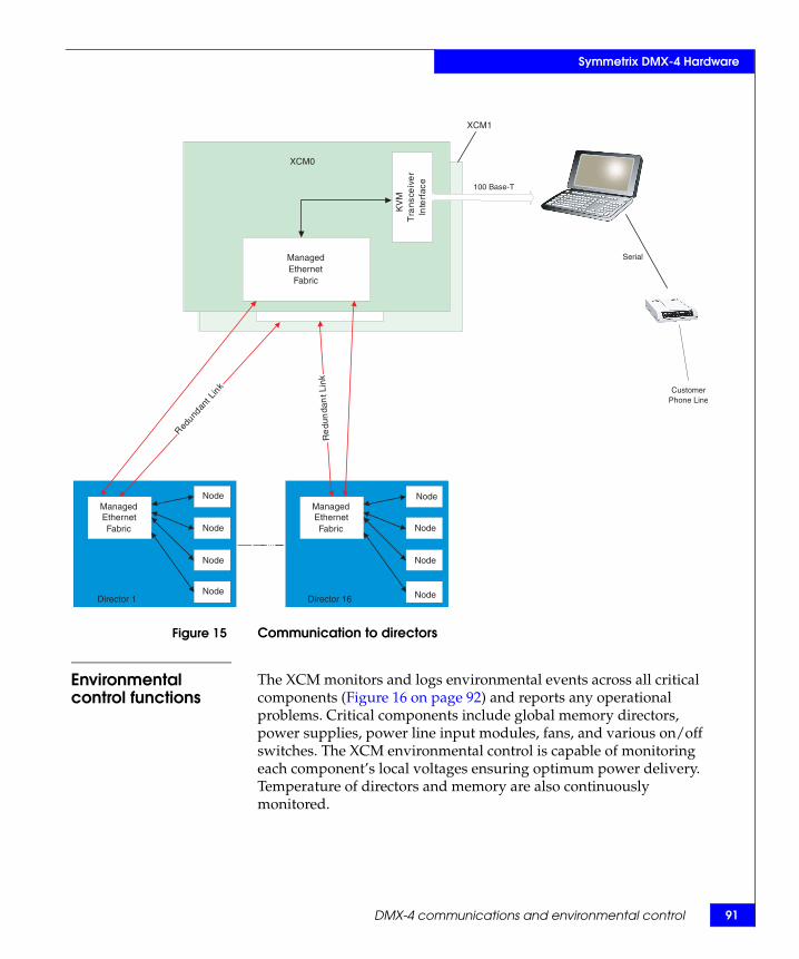
Symmetrix DMX-4 Hardware
Figure 15 Communication to directors
Environmental control functions
The XCM monitors and logs environmental events across all critical components (Figure 16 on page 92) and reports any operational problems. Critical components include global memory directors, power supplies, power line input modules, fans, and various on/off switches. The XCM environmental control is capable of monitoring each component’s local voltages ensuring optimum power delivery. Temperature of directors and memory are also continuously monitored.
Serial
ManagedEthernetSwitch
PowerPC
860DP
Lap
top
Tra
nsce
iver
Inte
rfac
e
CCM
ManagedEthernetFabric
Director 1
ManagedEthernetFabric
Node
Director 16
Redun
dant
Lin
k
Re
dun
dan
t Lin
k
ManagedEthernet
Fabric
KV
MT
rans
ceiv
er
Inte
rfac
e
XCM0
XCM1
100 Base-T
Node
Node
Node
Node
Node
Node
Node
CustomerPhone Line
DMX-4 communications and environmental control 91
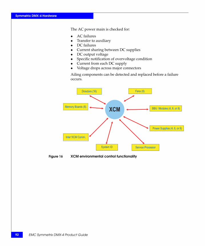
92
Symmetrix DMX-4 Hardware
EMC Symmetrix DMX-4 Product Guide
The AC power main is checked for:
◆ AC failures◆ Transfer to auxiliary ◆ DC failures◆ Current sharing between DC supplies◆ DC output voltage ◆ Specific notification of overvoltage condition◆ Current from each DC supply◆ Voltage drops across major connectors
Ailing components can be detected and replaced before a failure occurs.
Figure 16 XCM environmental control functionality
Directors (16)
Memory Boards (8)
Service Processor
Fans (9)
BBU Modules (4, 6, or 8)
Power Supplies (4, 6, or 8)
Inter-XCM Comm.
System ID
XCM

93
Symmetrix DMX-4 Hardware
Channel attachments
Channel attachmentsThe Symmetrix DMX-4 can attach to ESCON channels, FICON channels, or Fibre Channels, or a mix of channel types. The physical connection to a Symmetrix channel interface occurs at the connectors on the channel adapters.
Note: The Symmetrix Enterprise Storage Platform (ESP) option is required when both mainframe hosts (ESCON or FICON channels) and open systems hosts (Fibre Channels, iSCSI, or GigE SRDF) connect to the same Symmetrix system. Consult your local EMC Sales Representative for the most current list of supported hosts, models, operating systems, and EMC open systems host support policies, or refer to the EMC Powerlink website.
FICON channel interface connections
The Symmetrix DMX-4 FICON directors connect to mainframe hosts. The four-port, four-processor MPCD and the FICON adapter provide the capability for four concurrent operations through four physical interfaces for communicating with the FICON channels in host systems.
Note: For more information on the FICON director, refer to “FICON channel director” on page 81.
FICON channels use fiber-optic cables. The current FICON implementation supports data transfer rates up to 4 Gb/s. There are two types of fiber-optic cables: multimode and single-mode.
Note: Symmetrix systems directly connect to FICON single-mode or multimode cables. For information on additional configuration options, refer to “Symmetrix FICON configurations” on page 95.
In the FICON environment, a link connects a host FICON channel with a Symmetrix FICON channel interface. This link can be a direct connection between the processor or LPAR and the FICON channel interface. The link can also have a FICON director that branches off to additional single-mode or multimode links with connections to Symmetrix FICON channel directors. Figure 17 on page 94 illustrates several types of FICON channel attachments.
Table 21 on page 94 describes the maximum distances supported by FICON cables.
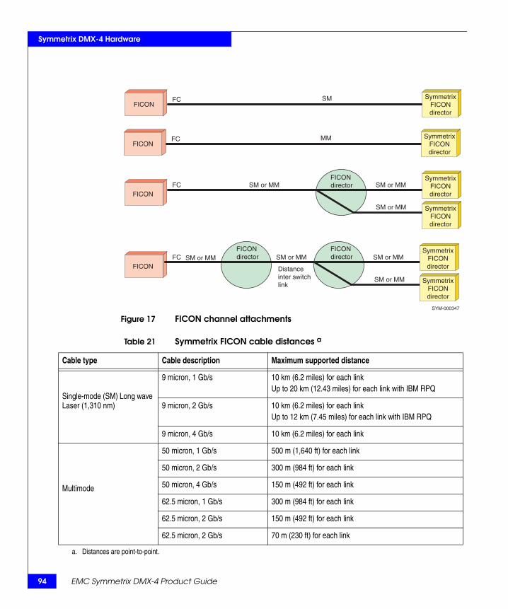
94
Symmetrix DMX-4 Hardware
EMC Symmetrix DMX-4 Product Guide
Figure 17 FICON channel attachmentsSYM-000347
SM or MMFICON director
FICON FC SM or MM
SM or MM SymmetrixFICONdirector
SM or MMFICON
FC SM or MM
SM or MM
SymmetrixFICONdirector
SymmetrixFICONdirector
Distance inter switchlink
SM or MM
SymmetrixFICONdirector
SMFCFICON
SymmetrixFICONdirector
MMFCFICON
SymmetrixFICONdirector
FICON director
FICON director
Table 21 Symmetrix FICON cable distances a
Cable type Cable description Maximum supported distance
Single-mode (SM) Long wave Laser (1,310 nm)
9 micron, 1 Gb/s 10 km (6.2 miles) for each linkUp to 20 km (12.43 miles) for each link with IBM RPQ
9 micron, 2 Gb/s 10 km (6.2 miles) for each linkUp to 12 km (7.45 miles) for each link with IBM RPQ
9 micron, 4 Gb/s 10 km (6.2 miles) for each link
Multimode
50 micron, 1 Gb/s 500 m (1,640 ft) for each link
50 micron, 2 Gb/s 300 m (984 ft) for each link
50 micron, 4 Gb/s 150 m (492 ft) for each link
62.5 micron, 1 Gb/s 300 m (984 ft) for each link
62.5 micron, 2 Gb/s 150 m (492 ft) for each link
62.5 micron, 2 Gb/s 70 m (230 ft) for each link
a. Distances are point-to-point.
Symmetrix DMX-4 Hardware
Symmetrix FICONconfigurations
In addition to the standard direct-connect configuration, Symmetrix DMX-4 FICON models support the use of Cascading and Open Systems Intermix configurations. Cascading can be used to reduce the number of FICON adapters and the amount of intersite cabling required by making use of switch-to-switch communication.
Intermix allows FICON zones to be added to existing Open Systems switches within a site and between sites. These two features help reduce the overall costs while providing greater FICON connectivity, backup, and recovery.
Note: For specific Cascading and Open System Intermix configuration requirements, contact your local EMC Sales Representative.
FICON cascading configurationsCascading provides greatly enhanced FICON connectivity within local and remote sites through the use of switch-to-switch extensions of the CPU to the DMX FICON network. These cascaded switches communicate over long distances using a small number of high speed lines called ISLs (InterSwitch Links). Up to a maximum of two switches may be connected together within a path between the CPU and the DMX.
Same switch vendors are required for a Cascaded configuration. The EMC and IBM branded McDATA and INRANGE switches are supported in pairs. To support Cascading, each vendor requires specific models, hardware and software features, configuration settings, and restrictions. Specific IBM CPU models, MVS release levels, channel hardware, and microcode levels are also required.
FICON open systems intermix configurationsOpen Systems Intermix allows separate FICON zones to be defined within new or existing open systems switches. These switches can also be Cascaded to further enhance connectivity and remote backup and recovery. The EMC and IBM branded McDATA and INRANGE switches are supported. To support Open Systems Intermix, each vendor requires specific models, hardware and software features, configuration settings, and restrictions. Specific IBM CPU models, MVS release levels, channel hardware, and microcode levels are also required.
Channel attachments 95
96
Symmetrix DMX-4 Hardware
EMC Symmetrix DMX-4 Product Guide
ESCON channel interface connections
The Symmetrix DMX-4 ESCON directors connect to mainframe hosts. The eight-port, four-processor ESCON director provides the capability for four concurrent operations through its four physical interfaces for communicating with the serial channels in host systems.
Note: “ESCON channel directors” on page 80 contain more information on the ESCON director.
ESCON channels use fiber optic cables. These serial channels are formally called the ESA/390 Enterprise Systems Connection Architecture (ESCON) I/O interface. The serial channels use point-to-point or switched point-to-point links. Each link has two physical fibers for transporting data: one for inbound signals and one for outbound signals. The current ESCON implementation supports data transfer rates up to 17 MB/s.
There are two types of fiber optic cables: multimode and single-mode. Multimode cables support a maximum link of 1.86 miles (3 km). Single-mode cables support a maximum link of 12.42 miles (20 km) with the Extended Distance Feature (XDF).
Note: Symmetrix systems directly connect to ESCON multimode cables only.
In the ESCON environment, a link connects a host serial or ESCON channel with a Symmetrix serial channel (ESCON) interface. This link can be a direct connection between the processor, or LPAR, and the serial channel interface. This link can also have up to two ESCON Directors configured between the processor, or LPAR, and the serial channel interface. The Symmetrix system supports a maximum connection length of 26.7 miles (43 km) with two single-mode cables and one multimode cable.
Figure 18 on page 97 illustrates several types of ESCON channel attachments. Table 22 on page 98 describes cable types and supported distances.

97
Symmetrix DMX-4 Hardware
Channel attachments
Figure 18 ESCON channel attachments
Multimodefiber optic
cables
Multimodefiber optic
cables
Multimodefiber optic
cables
Multimodefiber optic
cables
Multimodefiber optic
cables
Multimodefiber optic
cables
Multimodefiber optic
cables
Multimodefiber optic
cables
Single-modefiber optic
cables
Single-modefiber optic
cables
Single-modefiber optic
cables
ESCONchannel
ESCONchannel
ESCONchannel
ESCONchannel
ESCONchannel
Processoror LPAR
Processoror LPAR
Processoror LPAR
Processoror LPAR
Processoror LPAR
3 kmMax
3 kmMax
3 kmMax
3 kmMax
20 kmMax
20 kmMax
20 kmMax
3 kmMax
3 kmMax
3 kmMax
3 kmMax
SymmetrixESCONdirector
SymmetrixESCONdirector
SymmetrixESCONdirector
SymmetrixESCONdirector
SymmetrixESCONdirector
Repeater
Repeater
Repeater
Repeater Repeater
Repeater
FICON link
ESCON links
FICON LXFCV
FICON bridge card
9032-5 ESCD
MM
<= 3 km
SymmetrixESCONdirector
SymmetrixESCONdirector
SM
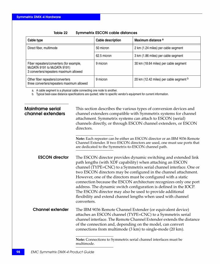
98
Symmetrix DMX-4 Hardware
Mainframe serial channel extenders
This section describes the various types of conversion devices and channel extenders compatible with Symmetrix systems for channel attachment. Symmetrix systems can attach to ESCON (serial) channels directly, or through ESCON channel extenders, or ESCON directors.
Note: Each repeater can be either an ESCON director or an IBM 9036 Remote Channel Extender. If two ESCON directors are used, one must use ports that are dedicated to the Symmetrix-to-ESCON channel path.
ESCON director The ESCON director provides dynamic switching and extended link path lengths (with XDF capability) when attaching an ESCON channel (TYPE=CNC) to a Symmetrix serial channel interface. One or two ESCON directors may be configured in the channel attachment. However, one of the directors must be configured with a static connection because the ESCON architecture recognizes only one port address. The dynamic switch configuration is defined in the IOCP. The ESCON director may also be used to provide additional flexibility and extend channel lengths when used with channel converters.
Channel extender The IBM 9036 Remote Channel Extender (or equivalent device) attaches an ESCON channel (TYPE=CNC) to a Symmetrix serial channel interface. The Remote Channel Extender extends the distance of the connection and, depending on the model, can convert connections from multimode (3 km) to single-mode (20 km).
Note: Connections to Symmetrix serial channel interfaces must be multimode.
Table 22 Symmetrix ESCON cable distances
Cable type Cable description Maximum distance a
Direct fiber, multimode 50 micron 2 km (1.24 miles) per cable segment
62.5 micron 3 km (1.86 miles) per cable segment
Fiber repeaters/converters (for example, McDATA 9191 to McDATA 9191)3 converters/repeaters maximum allowed
9 micron 30 km (18.64 miles) per cable segment
Other fiber repeaters/converters three converters/repeaters maximum allowed
9 micron 20 km (12.42 miles) per cable segment b
a. A cable segment is a physical cable connecting one node to another.b. Typical best-case distance specifications are quoted; refer to specific vendor’s equipment for current information.
EMC Symmetrix DMX-4 Product Guide

Symmetrix DMX-4 Hardware
Open systems Fibre Channel interface connections
The Symmetrix Fibre Channel adapter provides an interface between the director and open systems host channels. Each Fibre Channel adapter is located at the rear of the midplane, opposite its corresponding channel director. These adapters provide the connectivity between the host channels and the Fibre Channel directors (FC-0 layer of the Fibre Channel standard).
The eight-port Fibre Channel director provides the capability for eight concurrent operations through its eight physical interfaces for communicating with the host systems.
Note: “Fibre Channel directors front-end” on page 78 contains more information on the Fibre Channel director.
Fibre Channel directors use fiber optic cables. The channels use Fibre Channel arbitrated loop or switched fabric links. Each link has two physical fibers for transporting data: One for inbound signals and one for outbound signals. The current Fibre Channel implementation supports data transfer rates up to 4 Gb/s (Table 23 on page 99).c
Note: For more information on Fibre Channel attachments and cables, refer to the EMC Powerlink website.
Table 23 Symmetrix Fibre Channel cable distances a
Cable type Cable description Maximum distance
Single-mode
9 micron, 1 Gb/s 10 km (6.2 miles) per cable segment
9 micron, 2 Gb/s 10 km (6.2 miles) per cable segment
9 micron, 4 Gb/s 10 km (6.2 miles) per cable segment
Multimode
50 micron, 1 Gb/s 500 m (1,640 ft) per cable segment
50 micron, 2 Gb/s 300 m (984 ft) per cable segment
50 micron, 4 Gb/s 150 m (492 ft) per cable segment
62.5 micron, 1 Gb/s 300 m (984 ft) per cable segment
62.5 micron, 2 Gb/s 150 m (492 ft) per cable segment
62.5 micron,4 Gb/s 70 m (230 ft) per cable segment
a. Distances are point-to-point.
Channel attachments 99

100
Symmetrix DMX-4 Hardware
EMC Symmetrix DMX-4 Product Guide
3Invisible Body Tag
This chapter describes input and output operations between the Symmetrix DMX-4 system and a host system:
◆ Symmetrix DMX-4 operation ......................................................... 102◆ Elements of a Symmetrix I/O operation ...................................... 105◆ I/O performance enhancements.................................................... 113
Symmetrix DMX-4Input/Output
Operations
Symmetrix DMX-4 Input/Output Operations 101

102
Symmetrix DMX-4 Input/Output Operations
Symmetrix DMX-4 operationIntelligent global memory configurations allow Symmetrix DMX-4 disk systems to transfer data at electronic memory speeds that are much faster than physical disk speeds. Symmetrix systems are based on the principle that the working set of data at any given time is relatively small when compared to the total subsystem storage capacity. When this working set of data is in cache memory, there is a significant improvement in performance. The performance improvement achieved depends on both of the following principles:
◆ Locality of reference — If a given piece of information is used, there is a high probability that a nearby piece of information will be used shortly thereafter.
◆ Data re-use — If a given piece of information is used, there is a high probability that it will be re-used shortly thereafter.
These cache memory principles have been used for years on host systems (CPU and storage devices). Figure 19 on page 102 illustrates this type of host cache memory use. The cache memory used in this manner is often a high-speed, high-cost storage unit that functions as an intermediary between the CPU and main storage.
Figure 19 Host cache use
CPU
Host
Cachememory
Main memory
SYM-000420
EMC Symmetrix DMX-4 Product Guide
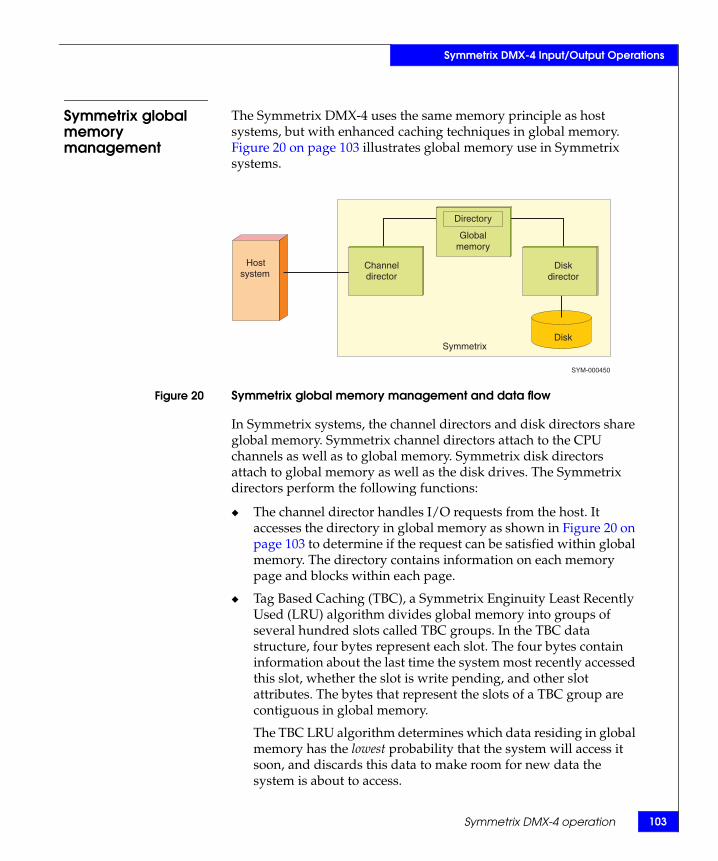
Symmetrix DMX-4 Input/Output Operations
Symmetrix global memory management
The Symmetrix DMX-4 uses the same memory principle as host systems, but with enhanced caching techniques in global memory. Figure 20 on page 103 illustrates global memory use in Symmetrix systems.
Figure 20 Symmetrix global memory management and data flow
In Symmetrix systems, the channel directors and disk directors share global memory. Symmetrix channel directors attach to the CPU channels as well as to global memory. Symmetrix disk directors attach to global memory as well as the disk drives. The Symmetrix directors perform the following functions:
◆ The channel director handles I/O requests from the host. It accesses the directory in global memory as shown in Figure 20 on page 103 to determine if the request can be satisfied within global memory. The directory contains information on each memory page and blocks within each page.
◆ Tag Based Caching (TBC), a Symmetrix Enginuity Least Recently Used (LRU) algorithm divides global memory into groups of several hundred slots called TBC groups. In the TBC data structure, four bytes represent each slot. The four bytes contain information about the last time the system most recently accessed this slot, whether the slot is write pending, and other slot attributes. The bytes that represent the slots of a TBC group are contiguous in global memory.
The TBC LRU algorithm determines which data residing in global memory has the lowest probability that the system will access it soon, and discards this data to make room for new data the system is about to access.
Hostsystem
Disk
Channeldirector
Directory
Globalmemory
Diskdirector
Symmetrix
SYM-000450
Symmetrix DMX-4 operation 103

104
Symmetrix DMX-4 Input/Output Operations
EMC Symmetrix DMX-4 Product Guide
◆ Using the prefetch algorithm, the disk director dynamically detects sequential data access patterns to the drives. The directors improve the hit ratio of these accesses by promoting blocks from the drives to global memory slots before that data has been requested. The prefetch algorithm is designed to minimize seek and latency on the disks, and to provide good response times.
◆ The disk director manages access to the disk drives. When a read miss occurs, the disk director also stages tracks into global memory. It also performs a background operation that destages written-to blocks to disk.
Prefetch algorithm Symmetrix systems continually monitor I/O activity and look for access patterns. When the second sequential I/O to a track occurs, the sequential prefetch process is invoked and the next track of data is read into global memory. The intent of this process is to avoid a read miss. When the host processor returns to a random I/O pattern, the Symmetrix system discontinues the sequential process.
The intelligent, adaptive prefetch algorithm reduces response time and improves the utilization of the disks. The prefetch algorithm maintains, per each logical volume, an array of statistics and parameters based on the latest sequential patterns observed on the logical volume. Prefetch dynamically adjusts, based on workload demand across all resources in the back end of the Symmetrix system. This algorithm also ensures that global memory resources are never overly consumed in order to maintain optimal performance.
Enginuity uses an intelligent algorithm attuned to “real-life” workloads and dynamic usage patterns which will detect sequences quickly, but prefetch only when the probability of increasing global memory hits is high. It will place data in memory on time and without interfering with other system activities. The prefetch to memory resulting in global memory hits dramatically improves response to a host request by as much as a factor of 10. It also optimizes back-end utilization by transferring large portions of data in each instance, minimizing seek and latency delays associated with I/O operations directly from disk.
By incorporating intelligent prefetch algorithms, Enginuity prefetches all the data that is needed—and only the needed data—and does it on time, without affecting the response time of other I/O events. Enginuity’s algorithms are the most sophisticated and advanced in the industry and are optimized for what you need next. They can adjust for real-world situations and intelligently choose the method that works best for a given situation.

Symmetrix DMX-4 Input/Output Operations
Elements of a Symmetrix I/O operationAll I/O operations require a certain response time. An I/O request begins when the application issues an I/O command and ends when the data transfer completes. The time interval from I/O request to transfer completion is the I/O response time.
This section describes:
◆ “I/O response time: Mainframe environment” on page 105◆ “I/O response time: Open systems environment” on page 106◆ “Symmetrix I/O operations” on page 106◆ “Read operations” on page 108◆ “Write operations” on page 110◆ “Write destaging operation” on page 112
I/O response time: Mainframe environment
In the mainframe environment, I/O response time can be divided into a queuing time, a pend time, a connect time, and a disconnect time, as shown in Figure 21 on page 105.
Figure 21 I/O response time (mainframe environment)
The Queuing time is the I/O Supervisor (IOS) queue for next the event.
The Pend time consists of:
◆ Control Unit Busy (CUB)◆ Device Busy (DB)◆ Director Port Busy
The Connect time is the length of time the channel processes commands and transfers data.
The Disconnect time is:
◆ The length of time it takes to retrieve data from the physical disk (device seek and latency).
◆ The length of time it takes to reconnect to the host.
◆ SRDF write overhead (protocol, line latency, and so on).
Queuingtime
Pendtime
Connecttime
Disconnecttime
Device service time
I/O response time
Elements of a Symmetrix I/O operation 105

106
Symmetrix DMX-4 Input/Output Operations
I/O response time: Open systems environment
In the open systems environment, I/O response time can be divided into a host queuing time, a command connect time, a disconnect time, and a data connect time, as shown in Figure 22 on page 106.
Figure 22 I/O response time (open systems environment)
The Host queuing time is the time the request is in the host queue before it is dispatched on the Fibre Channel path.
The Command connect time is the length of time the channel is transferring a Fibre Channel command.
The Disconnect time is the length of time involving device seek and latency. During this time, the Fibre Channel path can be used by other devices.
Note: In case of a memory hit in an I/O request, the Disconnect Time requirement is eliminated.
The Data connect time is the length of time the channel is transferring data.
Symmetrix I/O operations
There are four basic types of Symmetrix I/O operations (Figure 23 on page 107):
◆ Read Hit◆ Read Miss◆ Fast Write◆ Delayed Fast Write
The Symmetrix system performs read operations from global memory and always processes write operations in global memory. This global memory operation is transparent to the host operating system. A read operation causes the channel director to scan the global memory directory for the requested data. If the requested data is in global memory, the channel director transfers this data immediately to the channel with a channel end and device end (or a SCSI good ending status).
Hostqueuing time
Command connect time
Disconnect time
Dataconnecttime
Device service time
I/O response time
SYM-000453
EMC Symmetrix DMX-4 Product Guide

Symmetrix DMX-4 Input/Output Operations
If the requested data is not in global memory, the disk director transfers the data from the disk drive to the global memory, and the channel director transfers the requested data from the global memory to the channel.
Figure 23 Symmetrix I/O operations
Channeldirector
Channel Channel
Global memory
Directory
Channeldirector
Global memory
Directory
Diskdirector
Disk Diskdirector
Disk
Read hit Read miss
Channel Channel
Channeldirector
Directory
Global memory
Channeldirector
Directory
Global memory
Diskdirector
Disk
Diskdirector
Disk
Fast write Delayed fast write
1 Search-hit global memory directory2 Transfer to host3 Update directory
1 Search-miss global memory directory2 Position R/W head, stage data3 Transfer to the host4 Update directory
1 Search-hit global memory directory2 Transfer to global memory3 Update directory4 Destage asynchronously
1 Search global memory directory (global memory is full)2 Destage page3 Update global memory directory4 Transfer to global memory5 Update directory6 Destage asynchronously
5
3
2, 6
4 12 1
3
4
2 1
3
3 1
4
2
Elements of a Symmetrix I/O operation 107
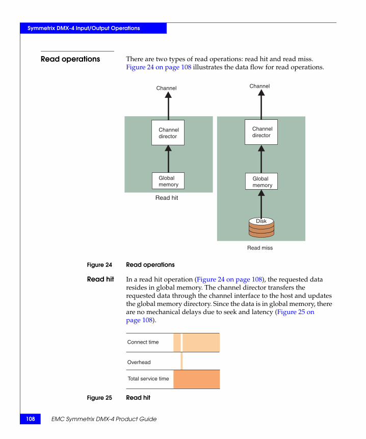
108
Symmetrix DMX-4 Input/Output Operations
Read operations There are two types of read operations: read hit and read miss. Figure 24 on page 108 illustrates the data flow for read operations.
Figure 24 Read operations
Read hit In a read hit operation (Figure 24 on page 108), the requested data resides in global memory. The channel director transfers the requested data through the channel interface to the host and updates the global memory directory. Since the data is in global memory, there are no mechanical delays due to seek and latency (Figure 25 on page 108).
Figure 25 Read hit
Channel Channel
Channeldirector
Channeldirector
Global memory
Global memory
Read hit
Read miss
Disk
Connect time
Overhead
Total service time
EMC Symmetrix DMX-4 Product Guide
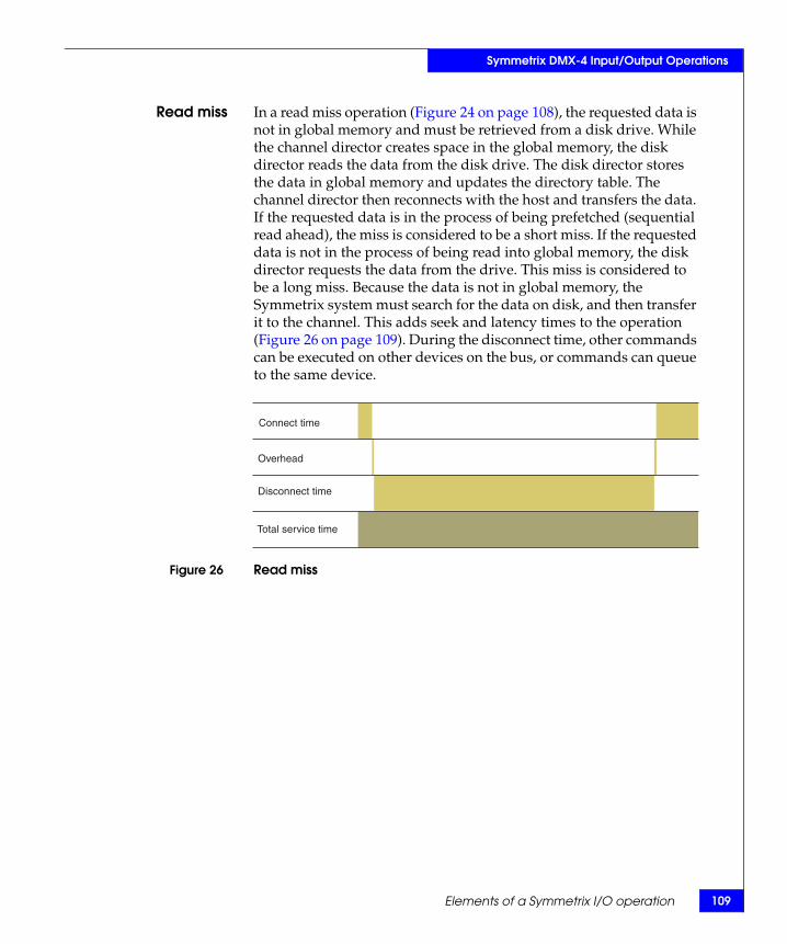
09
Symmetrix DMX-4 Input/Output Operations
Elements of a Symmetrix I/O operation 1
Read miss In a read miss operation (Figure 24 on page 108), the requested data is not in global memory and must be retrieved from a disk drive. While the channel director creates space in the global memory, the disk director reads the data from the disk drive. The disk director stores the data in global memory and updates the directory table. The channel director then reconnects with the host and transfers the data. If the requested data is in the process of being prefetched (sequential read ahead), the miss is considered to be a short miss. If the requested data is not in the process of being read into global memory, the disk director requests the data from the drive. This miss is considered to be a long miss. Because the data is not in global memory, the Symmetrix system must search for the data on disk, and then transfer it to the channel. This adds seek and latency times to the operation (Figure 26 on page 109). During the disconnect time, other commands can be executed on other devices on the bus, or commands can queue to the same device.
Figure 26 Read miss
Connect time
Overhead
Disconnect time
Total service time

110
Symmetrix DMX-4 Input/Output Operations
Write operations Symmetrix systems use large global memory configurations, and 100 percent global memory fast writes to ensure the highest possible performance when writing data. Symmetrix systems write operations occur as either fast write or delayed fast write operations (Figure 23 on page 107).
Fast write A fast write occurs when the percentage of modified data in global memory is less than the fast write threshold. On a host write command, the channel director places the incoming blocks directly into global memory.
For fast write operations (Figure 27 on page 110), the channel director stores the data in global memory and sends a channel end and device end (or a SCSI good ending status) to the host computer. The disk director then asynchronously destages the data from global memory to the disk drive.
Figure 27 Write operations
Fast write also allows Symmetrix systems to accommodate bursts of writes at a speed above and beyond the speed that the hard drives allow. The negative effects of bursty writes are minimized through this algorithm.
Channel
Channeldirector
Global memory
Disk
Asynchronousdestage
Fast write
EMC Symmetrix DMX-4 Product Guide

Symmetrix DMX-4 Input/Output Operations
Because Symmetrix systems write the data directly to global memory and not to disk, there are no mechanical delays due to seek, latency, and RPS miss (Figure 28 on page 111).
Figure 28 Fast write
Delayed fast write A delayed fast write occurs only when the fast write threshold has been exceeded. That is, the percentage of global memory containing modified data is higher than the fast write threshold. If this situation occurs, the Symmetrix system disconnects the channel directors from the channels.
The disk directors then destage the Least Recently Used (LRU) data to disk. When sufficient global memory space is available, the channel directors reconnect to their channels and process the host I/O request as a fast write (Figure 29 on page 111). The Symmetrix system continues to process read operations during delayed fast writes. With sufficient global memory present, this type of global memory operation rarely occurs.
Figure 29 Delayed fast write
Connect time
Global memory
Total service time
Connect time
Overhead
Disconnect time
Total service time
Delay Normalfast write
Elements of a Symmetrix I/O operation 111

112
Symmetrix DMX-4 Input/Output Operations
EMC Symmetrix DMX-4 Product Guide
Write destaging operation
In addition to the four types of I/O operations explained earlier, Symmetrix systems perform a background operation that destages blocks back to disk. This allows any written-to or changed data to be maintained in two locations: in global memory for performance in the occurrence of re-use of that data and on disk to maintain the highest levels of data integrity. Any pending writes are assured of arrival to the intended disk, even in the event of power failure. Figure 30 on page 112 illustrates this destaging operation.
Figure 30 Destaging operation
For each logical volume the Symmetrix system maintains a special data structure that points to the data that needs to be destaged in the global memory Write Pending Indicators (WPIs) already discussed above. This dynamically adjusting algorithm saves disk seek and latency time by destaging data in groups of up to four tracks concurrently per logical volume.
Channel
Channeldirector
Directory
Globalmemory
Diskdirector
Disk
1 Destage blocks2 Update directory

Symmetrix DMX-4 Input/Output Operations
I/O performance enhancementsSymmetrix systems use these techniques to enhance performance:
◆ Split director functions — The director operations are split into two functional parts, the channel director and disk director. The channel director services requests from the host.
The disk director services requests between global memory and disk. Splitting the director functions eliminates the processing overhead and global memory locking associated with Control Units that perform both functions.
◆ Multiple disk directors — The disk directors support Fibre Channel drive loops ranging from 15 drives to 60 drives per loop. “Fibre Channel disk subsystem” on page 62 and “Fibre Channel disk directors back-end” on page 84 contain more information on director and disk combinations.
◆ High-speed global memory — Global memory speed is greater than the total speed of all components (for example, the directors) that access it.
◆ Disk microprocessor and buffer — Each disk device has its own microprocessor and buffer that respond to the actuator level, providing parallel processing of data. These features add another level of global memory processing and improve overall performance.
◆ Sequential access patterns — Access patterns can be sequential, random, or a combination of both. When a miss occurs on a sequential access pattern, the number of blocks brought into global memory increases, which improves the hit rate because the requested data is in global memory.
I/O performance enhancements 113

114
Symmetrix DMX-4 Input/Output Operations
EMC Symmetrix DMX-4 Product Guide

4Invisible Body Tag
This chapter describes the performance features of the Symmetrix DMX-4 and explains how to optimize the following features:
◆ Overview........................................................................................... 116◆ Global memory performance features .......................................... 117◆ Symmetrix file system performance features .............................. 122◆ Multiple channel directors.............................................................. 124◆ Open systems hypervolumes ......................................................... 127◆ Mainframe systems hypervolumes ............................................... 132◆ Tiered storage optimization............................................................ 136◆ Optimizing Symmetrix system performance............................... 139◆ Dynamic Host Addressing ............................................................. 145◆ Virtual Provisioning......................................................................... 146◆ Multiport volume access for open systems environments ........ 149◆ Software options overview............................................................. 150
Performance andOptimization
Performance and Optimization 115
116
Performance and Optimization
OverviewReal-world workloads consist of many different types of I/O activity. They can be read or write requests, have different data block sizes, or be skewed (some disks or host channels doing more work than others). They can also be highly random, sequential, or mixed, and they are often bursty (peak reads or writes can come at unexpected times). The workloads used for envelope measurements are normally static, simple, and designed to always yield certain levels of hit ratio (access of read/write data directly out of global memory), regardless of the global memory size and algorithms. In the real world, the actual application behavior is greatly influenced by the performance optimization algorithms.
Symmetrix Enginuity contains extensive algorithmic intelligence that is designed to deliver fast application response time. These algorithms optimize use of internal resources and allow end-user definition of priorities for Symmetrix operations. These unique algorithms balance the load evenly among Symmetrix components, save valuable resources, and optimize data layout based on detection of long-term workload patterns.
The Symmetrix DMX-4 offers improved performance over conventional storage control units and DASD designs. The Symmetrix features described in this section allow high global memory hit ratios and less processing overhead, thus reducing response time and improving throughput.
The Symmetrix Enginuity performance optimization features are summarized in the following sections.
EMC Symmetrix DMX-4 Product Guide

Performance and Optimization
Global memory performance featuresThe Symmetrix DMX-4 global memory director design provides point-to-point, nonblocking connectivity between the front-end channel directors and back-end disk director. Each global memory director is physically partitioned into four separately addressable simultaneously accessible regions. These offload engines, utilizing Symmetrix DMX-4 technology, implement advanced techniques while securing data integrity and optimizing available resource usage. This EMC exclusive global memory design managed by EMC’s Enginuity Storage Operating Environment delivers a high performance, fault tolerant, ultra-reliable system.
The global memory directors deliver consistently high levels of system performance, improve responsiveness and consistency of responsiveness, and manage peak I/O requests through a series of techniques that essentially eliminate contention for shared global memory and optimize utilization of system resources. The underlying principles are:
◆ Global memory is composed of up to eight global memory directors that provide up to 512 GB (256 GB effective) of global memory in the DMX-4.
◆ Requests for global memory are expedited to reduce locking.
◆ Requests are intelligently arbitrated to optimize available resource usage.
This section describes the following Enginuity-supported global memory performance features:
◆ “Global memory ASICs” on page 118◆ “Tag Based Caching (TBC)” on page 119◆ “Fast write capabilities” on page 120◆ “Dynamic Mirror Service Policy (DMSP) algorithm” on page 120◆ “Disk Rotational Position Ordering (RPO)” on page 120◆ “Disk Multiple Priority Queues (DMPQ)” on page 120◆ “PermaCache option” on page 121
Global memory performance features 117

118
Performance and Optimization
Global memory ASICs
The global memory directors expedite transactions between process requests and global memory. EMC’s global memory directors use Application Specific Integrated Circuits (ASICs) technology that acts as intelligent offload engines to perform repetitive system critical functions. Global memory ASICs consist of the following components:
◆ “Parallel global memory regions” on page 118◆ “Buffering” on page 118◆ “Access arbitration” on page 118◆ “Memory striping” on page 118
Parallel globalmemory regions
Symmetrix DMX-4 global memory architecture drastically reduces memory contention by partitioning the global memory into four separately addressable, simultaneously accessible regions. In a Symmetrix DMX-4 with eight global memory directors, there are 32 separately addressable and accessible global memory regions. The DMX-4 with four global memory directors supports 16 separately addressable and accessible global memory regions.
Buffering Global memory ASICs buffer incoming requests from front-end channel directors and, as soon as possible, free up the global memory region being accessed. The result is a truly nonblocking architecture that is capable of massive performance scaling.
Access arbitration Global memory directors also arbitrate incoming requests for global memory resources in such a way as to optimally allocate global memory regions to incoming requests by appropriately timing and intelligently prefetching required information from global memory into the buffer. This results in optimal utilization of available resources.
Memory striping To eliminate any contention that may occur while working with large chunks of data, global memory directors stripe any data that resides on global memory across all the four regions within each global global memory director. Striping is carried out in units of 64 memory words1 across the four regions of each global memory director.
1. David E. Culler, Jaswinder Pal Singh, 1999: Parallel Computer Architecture, Morgan Kaufmann.
EMC Symmetrix DMX-4 Product Guide

Performance and Optimization
For example, for an instruction requesting to write 256 memory words of data to a given address, the global memory director will break out this request into four bursts:
◆ The first 64-word chunk (from 1 to 64) is written to region 1.◆ The second chunk (from 65 to 128) is written to region 2.◆ The third chunk (from 129 to 192) is written to region 3.◆ The last chunk (from 193 to 256) is written to region 4.
Striping of data across the four memory regions on the global memory directors eradicates any contention for I/O through global memory.
Tag Based Caching (TBC)
Enginuity uses Tag Based Caching (TBC) Least Recently Used (LRU) algorithm for cache management. Enginuity divides global memory into groups of several hundred slots. In the TBC data structure, four bytes represent each slot. The four bytes contain information about the last time the system most recently accessed this slot, whether the slot is write pending, and other attributes. Each memory slot is represented by one tag. Tags are clustered into groups called extents.
The TBC LRU algorithm determines which slot in an extent was least recently used. This TBC LRU slot then loses its association with the track/data that is stored. Getting a new slot means reading all the presenting bytes of a TBC extent and choosing the oldest one to be replaced. Changing one bit removes it from the LRU pool of available slots. Figure 31 on page 119 illustrates the TBC LRU process.
Figure 31 TBC LRU function
All the CPUs in a Symmetrix system access all the TBC extents. Enginuity manipulates the TBC extent under lock. To avoid contention over one TBC extent, each CPU in the Symmetrix system accesses the TBC extents in a different order, which guarantees even loads on the different TBC extents at any given time. TBC simplifies LRU implementation.
…
Each color represents a different “slot age”
Best candidates for replacement
extent 1 extent 2 extent n
Global memory performance features 119

120
Performance and Optimization
Fast write capabilities
Symmetrix systems process all write operations in global memory, eliminating the need to write data to the disk immediately. This capability results in faster response times and improved overall subsystem performance. Channel directors and disk directors dynamically allocate global memory space between reads and writes, depending on I/O activity.
Dynamic Mirror Service Policy (DMSP) algorithm
When implementing mirroring (RAID 1) data protection in Symmetrix systems, DMSP determines which of the mirrors of a given logical volume should service a read miss (when the data is not found in global memory) operation. Attached BCVs can also participate in the DMSP. DMSP provides a dynamic approach to setting the optimal mirror service policy. The DMSP algorithm monitors the access patterns to the different logical volumes in the Symmetrix back end and, based on this, determines a policy for the next few minutes. The DMSP tries to achieve two goals:
◆ Balance the load among all of Symmetrix back-end components. ◆ Minimize the seek time spent on the physical drives.
Note: DMSP also works with the Symmetrix file system as described in “Enhancement of dynamic mirror service policy” on page 122.
Disk Rotational Position Ordering (RPO)
Disk Rotational Position Ordering (RPO) optimization can more than double the number of random I/Os a disk can do. Whenever multiple I/O requests are queued on the disk, the EMC Enginuity Operating Environment can optimize the order in which the I/Os are executed. The RPO optimization reorders the I/Os based on their physical location on the drive. RPO optimization significantly reduces the effect of seeks and latency times on the overall performance of the disk. To take full advantage of the RPO optimization, the Symmetrix system needs to queue enough I/Os on the physical drives. The more I/O demand the Symmetrix system encounters, the better it will perform.
Disk Multiple Priority Queues (DMPQ)
Disk Multiple Priority Queues enable the Symmetrix system to give better response times to I/Os that the hosts are waiting for, without sacrificing the disk RPO optimization. The multiple-priority queues algorithm handles starvation situations, so even the low priority I/Os are serviced within a time-optimized period.
EMC Symmetrix DMX-4 Product Guide

Performance and Optimization
PermaCache option The PermaCache option allows you to permanently assign mission-critical data requiring very high performance to global memory. A variable number of contiguous cylinders on the drives can be reserved for PermaCache backup.
PermaCache is best used for infrequently accessed data that needs instantaneous response because this data is normally not in global memory when it is requested. The Symmetrix large global memory and intelligent global memory algorithms try to keep frequently accessed data in global memory, making its assignment to PermaCache unnecessary.
Other Symmetrix options that require global memory resources affect the amount of global memory available for PermaCache. For example, enabling the RAID 6 options (in (6+2) or (14+2) mode) may require adjusting memory assignments by reducing the existing PermaCache area, lowering the write-pending ceiling of the system, or reducing the number of Symmetrix RAID 6 groups defined.
Global memoryrequirements
Your system must be configured with more than the minimum (base) amount of global memory for it to use part of that memory as PermaCache. To determine the minimum memory requirement for your Symmetrix configuration, consult your local EMC Sales Representative.
Power failures If a power failure occurs, records that have been updated in PermaCache will be destaged to disk.
Global memorydirector replacement
If a global memory director requires online replacement, PermaCache is unaffected, provided that the replacement board contains the same amount or greater of global memory. Replacement with a smaller capacity memory requires that the system be brought offline and reinitialized before PermaCache will function.
Online PermaCacheconfiguration
changes
Symmetrix Enginuity permits PermaCache configurations to be changed while the Symmetrix system is online to the host. Enabling PermaCache modifications to take place through an online configuration change allows users to set a configuration with no disruptions and avoids requirements for future maintenance.
Global memory performance features 121

122
Performance and Optimization
Symmetrix file system performance featuresEnginuity automatically reserves 24 GB (raw) for internal use as a Symmetrix File System (SFS). This space is automatically allocated while initially loading the Enginuity Operating Environment on Symmetrix systems and is not visible to the host environment. SFS reserves two SFS logical volumes consisting of 6,140 cylinders each (slightly less than 6 GB). These volumes are protected using mirroring, consuming slightly less than 24 GB total physical space.
The SFS generates several benefits for Symmetrix users, namely:
◆ “Dynamically adjusting performance algorithms” on page 122◆ “Enhancement of dynamic mirror service policy” on page 122◆ “Enhancement of Symmetrix Optimizer” on page 122◆ “Enhanced system audit and investigation” on page 123
Dynamically adjusting performance algorithms
State-of-the-art information management algorithms implemented within Enginuity need to store and use statistical data gathered over time. SFS provides a place to store this statistical database that Enginuity creates and uses to dynamically optimize algorithms and optimize performance.
Enhancement of dynamic mirror service policy
Enginuity uses SFS to store the data from sampling for Symmetrix dynamic mirror service policy (DMSP). DMSP algorithms within Enginuity collect logical volume activity samples, store this information in SFS, and use this information to make mirror service policy decisions that further enhance Symmetrix RAID 1 and RAID 10 performance.
Enhancement of Symmetrix Optimizer
Enginuity uses SFS to store information on physical spindle activity and other mirror activity. This data is used to plot a thermograph of hot (busy) and cold (idle) spindles. This thermographical information gathered over a long time period and preserved in SFS is used to determine the hottest (busiest) and the coldest (idlest) spindles and to recommend swaps.
EMC Symmetrix DMX-4 Product Guide

Performance and Optimization
Enhanced system audit and investigation
Enginuity stores an Audit Log in the SFS. This enables improved investigation, both at the system level and customer environment level. Symmetrix Audit Log collects and presents a chronological list of host-initiated Symmetrix actions and activities. Manual activities (for example, physically removing/replacing a component) as well as automatically initiated scripts and EMC’s Solutions Enabler activities (for example, TimeFinder or SRDF routines) are tracked and recorded in the SFS. This provides a means to oversee and historically recall how and when a Symmetrix device is being used.
Enginuity also expands capabilities for host applications built on SymmAPI™. Earlier, host applications were allowed to make entries to a Symmetrix write-only buffer. Audit Log features now enable Symmetrix ISVs and other service providers to use logged information for their own reporting purposes. The built-in system security in SymmAPI does not allow host applications to change audit logs. This reduces IOSQ (I/O Supervisor Queue Time) exposure and increases system performance.
An enhanced feature of the Symmetrix Audit Log allows the CE/PSE to log Inlines commands to the audit log with a customer-meaningful descriptions. This ensures that customers are able to monitor and create an audit trail for all work performed by EMC personnel.
Note: “Symmetrix Audit Log” on page 185 contains additional information.
Symmetrix file system performance features 123

124
Performance and Optimization
EMC Symmetrix DMX-4 Product Guide
Multiple channel directorsThe Symmetrix DMX-4 channel directors process data from the host and manage access to global memory over a direct matrix technology (Figure 8 on page 54). Each channel director on the Symmetrix DMX-4 supports eight internal links to global memory. The Symmetrix DMX-4 may support up to 12 qualified channel directors that support connectivity to either mainframe systems or open systems hosts.
“Channel director descriptions” on page 77 contains detailed information on each Symmetrix channel director. Contact your local EMC Sales Representative for specific supported channel director configurations.
Note: A Symmetrix DMX-4 can support simultaneous connections to mainframe systems hosts and open systems hosts when the required Symmetrix ESP software is installed on the Symmetrix system.
The DMX-4 supports these channel directors:
◆ ESCON directors (mainframe hosts)◆ Fibre Channel directors (open systems hosts)◆ Multiprotocol channel directors with these mezzanine card
connections for:• Fibre Channel (open systems hosts)• GigE for SRDF connectivity
Note: Contact your local EMC Sales Representative for GigE remote support availability.
• GigE IPv4/v6 (IPsec capable)• iSCSI (open systems hosts)• FICON (mainframe hosts)
Channel speeds and cable lengths
Symmetrix system channel speeds (data transfer rate) and cable lengths vary according to the type of channel director. This section describes the data transfer rates and supported cable lengths for the different channel directors.
Fibre Channels Fibre Channels transfer data at speeds up to 4 Gb/s. Symmetrix systems support multimode cable lengths from 10 ft (3 m) to 1,640 ft (500 m).

Performance and Optimization
Note: Table 23 on page 99 provides more detailed supported cable distance information. Table 59 on page 307 provides part numbers for EMC Fibre Channel cables.
ESCON channels Symmetrix ESCON channels transfer data at speeds up to 17 MB/s. The data transfer rate depends upon the host system. Symmetrix systems support ESCON fiber cable connections to 26.7 miles (43 km) using repeaters in combination with multimode and single-mode connections Figure 18 on page 97 and Table 22 on page 98.
Note: Table 62 on page 310 provides part numbers for ESCON channel cables.
FICON channels Symmetrix FICON channels transfer data at speeds up to 4 Gb/s. The DMX-4 FICON design auto-detects 4 Gb/s, 2 Gb/s, or 1 Gb/s at switch or channel port login time.
Symmetrix systems support FICON fiber cable connections up to 7.45 miles (12 km) with single-mode connections.
Note: Table 21 on page 94 provides more detailed supported cable distance information. Table 63 on page 311 provides part numbers for FICON channel cables. For information on FICON multimode configuration support, contact your local EMC Sales Representative.
iSCSI channels Symmetrix iSCSI channels transfer data at speeds up to 1Gb/s. Symmetrix systems support iSCSI cable connections up to 524.93 ft (160 m) with multimode connections.
GigE remote channels Symmetrix GigE remote channels for SRDF transfer data at speeds up to 1Gb/s. Symmetrix systems support GigE remote cable connections up to 524.93 ft (160 m) with multimode connections.
Note: Contact your local EMC Sales Representative for GigE remote support availability.
Multiple channel directors 125

126
Performance and Optimization
Host connectivity Symmetrix DMX-4 supports connectivity to open systems hosts such as UNIX, Linux, and Windows systems through iSCSI, GigE (SRDF), and Fibre Channels. The Symmetrix DMX-4 supports mainframe systems host connectivity through ESCON and FICON channels.
Note: Symmetrix DMX-4 only supports Fibre Channel connectivity for iSeries hosts. The Symmetrix DMX-4 can support simultaneous connections to mainframe systems hosts and open systems hosts when the required Symmetrix ESP software is installed on the Symmetrix system.
EMC Symmetrix DMX-4 Product Guide
Performance and Optimization
Open systems hypervolumes This section describes the Hypervolume Extension feature on Symmetrix open systems units. It includes the following information:
◆ “Hypervolume extension feature” on page 127◆ “Disk drive cylinders” on page 127◆ “Logical volume mapping” on page 128◆ “Metavolumes” on page 129
Note: “Mainframe systems hypervolumes” on page 132 provides information on using the hypervolume extension feature in Symmetrix units connected to mainframe hosts.
Hypervolume extension feature
The hypervolume extension feature provides configuration flexibility by allowing one physical device to be split into two or more logical volumes. This capability is particularly useful for some 32-bit implementations of UNIX that allow only 2 GB file systems per single logical disk.
The Symmetrix DMX-4 allows up to 160 logical volumes on each Symmetrix DMX-4 open systems physical disk drive and up to 64,000 logical volumes (address range 0x000–0xF9FF) per Symmetrix DMX-4 system, depending on the hardware configuration and the data protection options.
Contact your local EMC Sales Representative for the number of logical volumes currently supported per DMX-4 system.
Note: “Symmetrix DMX-4 logical volume capacities” on page 68 contains more information on logical volumes supported on Symmetrix DMX-4 drives and systems. Configuration requirements for Symmetrix systems vary according to the applications used. To configure logical volumes for optimum Symmetrix system performance, consult your local EMC Sales Representative.
Disk drive cylinders The Symmetrix DMX-4 uses 3.5-inch, low-profile drives that are available in the following storage capacities and maximum usable Symmetrix cylinders (Table 24 on page 128).
Open systems hypervolumes 127
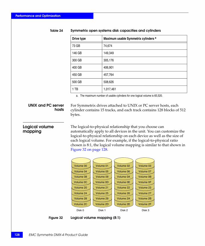
128
Performance and Optimization
UNIX and PC serverhosts
For Symmetrix drives attached to UNIX or PC server hosts, each cylinder contains 15 tracks, and each track contains 128 blocks of 512 bytes.
Logical volume mapping
The logical-to-physical relationship that you choose can automatically apply to all devices in the unit. You can customize the logical-to-physical relationship on each device as well as the size of each logical volume. For example, if the logical-to-physical ratio chosen is 8:1, the logical volume mapping is similar to that shown in Figure 32 on page 128.
Figure 32 Logical volume mapping (8:1)
Table 24 Symmetrix open systems disk capacities and cylinders
Drive type Maximum usable Symmetrix cylinders a
73 GB 74,674
146 GB 149,349
300 GB 305,176
400 GB 406,901
450 GB 457,764
500 GB 508,626
1 TB 1,017,461
a. The maximum number of usable cylinders for one logical volume is 65,520.
Volume 00 Volume 01 Volume 02 Volume 03
Volume 04 Volume 05 Volume 06 Volume 07
Volume 08 Volume 09 Volume 0A Volume 0B
Volume 0C Volume 0D Volume 0E Volume 0F
Volume 20 Volume 21 Volume 22 Volume 23
Volume 24 Volume 25 Volume 26 Volume 27
Volume 28 Volume 29 Volume 2A Volume 2B
Volume 2C Volume 2D Volume 2E Volume 2F
Disk 0 Disk 1 Disk 2 Disk 3
EMC Symmetrix DMX-4 Product Guide
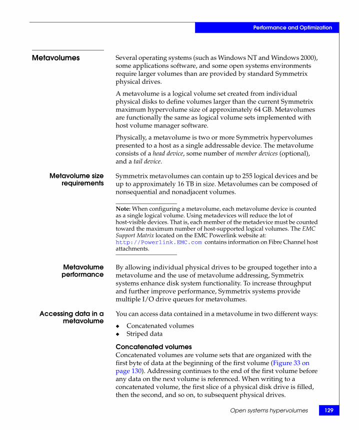
Performance and Optimization
Metavolumes Several operating systems (such as Windows NT and Windows 2000), some applications software, and some open systems environments require larger volumes than are provided by standard Symmetrix physical drives.
A metavolume is a logical volume set created from individual physical disks to define volumes larger than the current Symmetrix maximum hypervolume size of approximately 64 GB. Metavolumes are functionally the same as logical volume sets implemented with host volume manager software.
Physically, a metavolume is two or more Symmetrix hypervolumes presented to a host as a single addressable device. The metavolume consists of a head device, some number of member devices (optional), and a tail device.
Metavolume sizerequirements
Symmetrix metavolumes can contain up to 255 logical devices and be up to approximately 16 TB in size. Metavolumes can be composed of nonsequential and nonadjacent volumes.
Note: When configuring a metavolume, each metavolume device is counted as a single logical volume. Using metadevices will reduce the lot of host-visible devices. That is, each member of the metadevice must be counted toward the maximum number of host-supported logical volumes. The EMC Support Matrix located on the EMC Powerlink website at: http://Powerlink.EMC.com contains information on Fibre Channel host attachments.
Metavolumeperformance
By allowing individual physical drives to be grouped together into a metavolume and the use of metavolume addressing, Symmetrix systems enhance disk system functionality. To increase throughput and further improve performance, Symmetrix systems provide multiple I/O drive queues for metavolumes.
Accessing data in ametavolume
You can access data contained in a metavolume in two different ways:
◆ Concatenated volumes◆ Striped data
Concatenated volumesConcatenated volumes are volume sets that are organized with the first byte of data at the beginning of the first volume (Figure 33 on page 130). Addressing continues to the end of the first volume before any data on the next volume is referenced. When writing to a concatenated volume, the first slice of a physical disk drive is filled, then the second, and so on, to subsequent physical drives.
Open systems hypervolumes 129
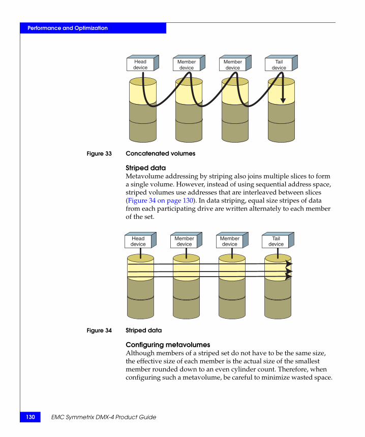
130
Performance and Optimization
Figure 33 Concatenated volumes
Striped dataMetavolume addressing by striping also joins multiple slices to form a single volume. However, instead of using sequential address space, striped volumes use addresses that are interleaved between slices (Figure 34 on page 130). In data striping, equal size stripes of data from each participating drive are written alternately to each member of the set.
Figure 34 Striped data
Configuring metavolumesAlthough members of a striped set do not have to be the same size, the effective size of each member is the actual size of the smallest member rounded down to an even cylinder count. Therefore, when configuring such a metavolume, be careful to minimize wasted space.
Headdevice
Memberdevice
Memberdevice
Taildevice
Headdevice
Memberdevice
Memberdevice
Taildevice
EMC Symmetrix DMX-4 Product Guide

Performance and Optimization
A customer can reconfigure metavolumes. While the Symmetrix system is online to the host, the customer can:
◆ Expand both concatenated and striped metavolumes.◆ Convert an unused volume to a concatenated or striped
metavolume.◆ Convert a populated volume to a concatenated or striped
metavolume.
Striping data across the multiple drives is designed to benefit random reads by avoiding stacking multiple reads to a single spindle and disk director. This scheme creates a large volume, but also balances the I/O activity between the drives and the Symmetrix disk directors.
Open systems hypervolumes 131

132
Performance and Optimization
Mainframe systems hypervolumes
Note: “Open systems hypervolumes” on page 127 provides information on this feature in Symmetrix systems connected to open systems hosts.
This section describes how to use the Hypervolume Extension feature on Symmetrix mainframe volumes. It contains the following topics:
◆ “Hypervolume extension options” on page 132◆ “Split-volume capability” on page 132◆ “Extended cylinder addressing option” on page 133◆ “Determining cylinders for hypervolume user data” on page 134
Hypervolume extension options
The Symmetrix system enhances disk system functionality by supporting multiple logical volumes on each physical device.
The hypervolume extension feature has two usage options:
◆ Split-volume capability — Allows up to 255 logical volumes on each Symmetrix DMX-4 physical disk drive depending on the data protection option used.
◆ Extended cylinder addressing — Establishes a small logical volume at the end of physical disk drive for data requiring high performance on a small volume.
Split-volume capability
Using the split-volume option of the Hypervolume Extension (HVE) feature, Symmetrix systems allow multiple logical volumes to reside on a single physical drive. This split-volume option provides for the consolidation of many physical DASD devices into far fewer physical high-capacity, high-performance disks.
Support is provided for native IBM 3390 and 3380 track emulation with all 3390 and 3380 disk volumes being supported. No modifications are required to the operating system, application, or program software to take advantage of HVE.
The split-volume option can override the one-to-one logical-to- physical relationship on all devices in the Symmetrix unit. The logical-to-physical relationship can automatically apply to all devices in the unit. You can also customize the logical-to-physical relationship on each device, as well as the size of each logical volume.
EMC Symmetrix DMX-4 Product Guide

33
Performance and Optimization
Mainframe systems hypervolumes 1
Symmetrix DMX-4 supports up to 255 logical volumes per physical disk drive and up to 64,000 logical volumes (address range 0x000– 0xF9FF) per system, depending on the Symmetrix DMX-4 hardware configuration and the data protection options.
Note: “Symmetrix DMX-4 logical volume capacities” on page 68 provides more information on logical volumes supported on Symmetrix DMX-4 drives and systems. Configuration requirements for Symmetrix systems vary according to the applications used. To configure logical volumes for optimum Symmetrix system performance, consult your local EMC Sales Representative.
Extended cylinder addressing option
Extended cylinder addressing places a small logical volume at the end of a disk drive. Each small logical volume can occupy a variable number of contiguous cylinders. This small logical volume can be as small as one cylinder in size. The maximum number of cylinders for this volume depends on the capacity of the disk drive and the emulation mode selected.
This flexibility in logical volume configuration increases system performance for datasets requiring extremely high performance such as Multi-Image Manager files, JES Checkpoint, RACF Control files, catalogs, and so on.
Because the data of interest resides on a small volume, the Unit Control Block (UCB) busy conditions that arise when this data is placed on larger capacity volumes with high activity are eliminated. This reduces IOSQ (I/O Supervisor Queue Time) exposure and increases system performance.
Note: Consult your EMC Systems Engineer regarding dataset placement on these small logical volumes.
This logical volume can be added to Symmetrix units that are configured and running without affecting existing data on the disk drive by giving the volume an address beyond any currently used on the unit. This option may also be used with the PermaCache option, in which infrequently accessed datasets requiring instantaneous access reside permanently in global memory.
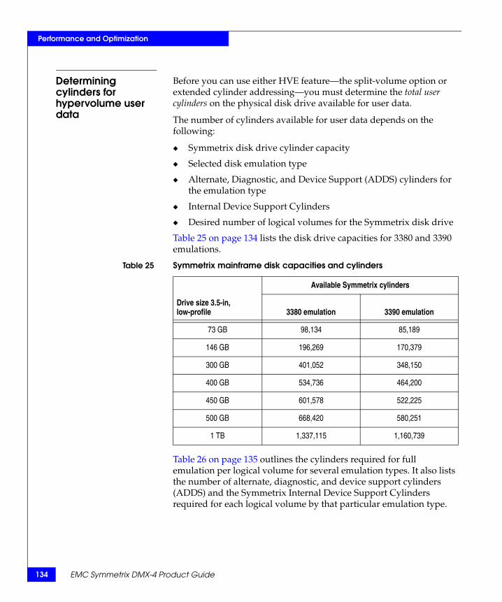
134
Performance and Optimization
Determining cylinders for hypervolume user data
Before you can use either HVE feature—the split-volume option or extended cylinder addressing—you must determine the total user cylinders on the physical disk drive available for user data.
The number of cylinders available for user data depends on the following:
◆ Symmetrix disk drive cylinder capacity
◆ Selected disk emulation type
◆ Alternate, Diagnostic, and Device Support (ADDS) cylinders for the emulation type
◆ Internal Device Support Cylinders
◆ Desired number of logical volumes for the Symmetrix disk drive
Table 25 on page 134 lists the disk drive capacities for 3380 and 3390 emulations.
Table 26 on page 135 outlines the cylinders required for full emulation per logical volume for several emulation types. It also lists the number of alternate, diagnostic, and device support cylinders (ADDS) and the Symmetrix Internal Device Support Cylinders required for each logical volume by that particular emulation type.
Table 25 Symmetrix mainframe disk capacities and cylinders
Available Symmetrix cylinders
Drive size 3.5-in, low-profile 3380 emulation 3390 emulation
73 GB 98,134 85,189
146 GB 196,269 170,379
300 GB 401,052 348,150
400 GB 534,736 464,200
450 GB 601,578 522,225
500 GB 668,420 580,251
1 TB 1,337,115 1,160,739
EMC Symmetrix DMX-4 Product Guide

Performance and Optimization
Note: Symmetrix DMX-4 systems can support 64K cylinder CKD devices for operating systems (Siemens) that can exploit it.
Table 26 Device emulations and number of cylinders
Emulation typeNumber of emulated cylinders
Alternate, diagnostic, device support cylinders (ADDS)
Symmetrix internal device support cylinders Total support cylinders
3380D 885 3 2 5
3380E 1,770 4 2 6
3380K 2,655 5 2 7
3390-1 1,113 4 2 6
3390-2 2,226 4 2 6
3390-3 3,339 4 2 6
3390-9 10,017 7 2 9
3390-27 32,760 0 2 2
3390-54 a 65,520 0 2 2
a. Contact your local EMC Sales Representative for currently supported IBM controller/DASD emulation modes.
Mainframe systems hypervolumes 135

136
Performance and Optimization
Tiered storage optimizationEnginuity 5772 provides two new SW offerings that improve the ability of organizations to store multiple tiers of data in a single Symmetrix, isolating cache resources and prioritizing I/O to ensure more predictable performance levels for different applications:
◆ Symmetrix Priority Controls
◆ Dynamic Cache Partitioning
Symmetrix Priority Controls
Symmetrix Priority Controls is an offering of 5772 that allows customers to modify the read I/O performance of devices configured in the Symmetrix in order to support preferential processing for specified application tiers with tiered storage in the array. The ability to control a device’s read priority is delivered using the following mechanisms:
◆ Prioritization — Ability to prioritize I/O by the Symmetrix device number. Devices can be grouped for ease of management.
◆ Priority queues — Globally set and execute prioritization of queue resources by cache, director and RDF I/O queue. There are 16 priority service levels (1 fastest to 16 slowest). Service levels are set per group of LUNs. The priority is set at the device level. Each level represents a time to become urgent value. The higher the priority level, the shorter the time to become urgent and the faster the read I/O processing will occur.
◆ Mainframe integration — Supports full integration with IBM’s Workload Manager for z/OS, responding to WLM commands.
◆ Performance and statistics reporting — The CE is able to control and query the behavior of the DMX-4 using internal functions. A new range of counters and statistics allows verification that Symmetrix Priority Controls is working as expected. These counters are grouped into three categories:
• Statistics (general/global system statistics)
• Priority statistics
• Device statistics
Symmetrix Management Console provides intuitive graphical controls and monitoring for Symmetrix Priority Controls. Priority Controls also can be managed and monitored using SymmCLI commands.
EMC Symmetrix DMX-4 Product Guide
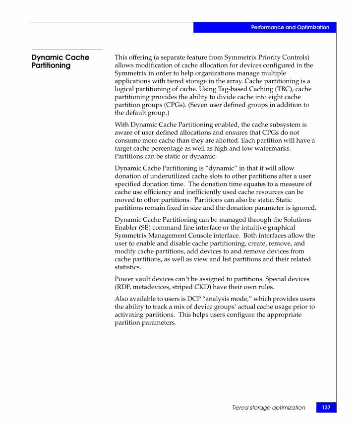
Performance and Optimization
Dynamic Cache Partitioning
This offering (a separate feature from Symmetrix Priority Controls) allows modification of cache allocation for devices configured in the Symmetrix in order to help organizations manage multiple applications with tiered storage in the array. Cache partitioning is a logical partitioning of cache. Using Tag-based Caching (TBC), cache partitioning provides the ability to divide cache into eight cache partition groups (CPGs). (Seven user defined groups in addition to the default group.)
With Dynamic Cache Partitioning enabled, the cache subsystem is aware of user defined allocations and ensures that CPGs do not consume more cache than they are allotted. Each partition will have a target cache percentage as well as high and low watermarks. Partitions can be static or dynamic.
Dynamic Cache Partitioning is “dynamic” in that it will allow donation of underutilized cache slots to other partitions after a user specified donation time. The donation time equates to a measure of cache use efficiency and inefficiently used cache resources can be moved to other partitions. Partitions can also be static. Static partitions remain fixed in size and the donation parameter is ignored.
Dynamic Cache Partitioning can be managed through the Solutions Enabler (SE) command line interface or the intuitive graphical Symmetrix Management Console interface. Both interfaces allow the user to enable and disable cache partitioning, create, remove, and modify cache partitions, add devices to and remove devices from cache partitions, as well as view and list partitions and their related statistics.
Power vault devices can’t be assigned to partitions. Special devices (RDF, metadevices, striped CKD) have their own rules.
Also available to users is DCP “analysis mode,” which provides users the ability to track a mix of device groups’ actual cache usage prior to activating partitions. This helps users configure the appropriate partition parameters.
Tiered storage optimization 137

138
Performance and Optimization
Each cache partition group (CPG) has its own definable write pending (WP) limit that can be varied from 40 percent to 80 percent. As the partition group’s write pending count approaches its write pending limit, the Symmetrix front-end adapters will introduce “WP fairness” delays to throttle host write activity. If write activity continues and the write pending limit is reached, priority destage operations take place on the Symmetrix back end. If the purpose of cache partitioning is to contain an application that produces many writes, then the write pending limit can be set to a premeditated low value. If operations consistent with the system write pending limit are desired, this parameter should be left at 80 percent.
EMC Symmetrix DMX-4 Product Guide

39
Performance and Optimization
Optimizing Symmetrix system performance 1
Optimizing Symmetrix system performanceAchieving optimal performance requires careful and detailed planning of the Symmetrix configuration according to the requirements of the host you are connecting to the Symmetrix system and your performance needs.
Carefully review the issues listed below with your EMC representative before the EMC Customer Engineer installs the Symmetrix system. Appendix C, “Planning and Installation,” includes sample worksheets and checklists to assist you in this process.
Performance guidelines for open system devices
Resolve the following open system device issues before installing your Symmetrix system:
◆ Rank distributed workloads from the busiest to the least busy (when configuring multiple hosts to a Symmetrix unit).
◆ Determine data storage capacity required for each host connected to the Symmetrix system.
◆ Determine the number of channels available from each host.
◆ Analyze the nature of the applications executed on the host connected to the Symmetrix system.
◆ Determine the availability of a Logical Volume Manager (LVM) on the host and the use of data striping.
◆ Determine and record the use of hypervolumes on the Symmetrix system, hypervolume size, and the allocation of hypervolumes between different hosts, different channels, and different applications.
◆ Determine the maximum drive and file system sizes supported by each host connected to the Symmetrix system.
◆ Analyze the requirements for device sharing.
◆ Define the number of Fibre Channel directors used and the number of ports used on each director.
◆ Define any special considerations for host-level mirroring for device distribution in the Symmetrix system.
◆ Plan for the possibility of upgrading the Symmetrix system with additional drives in the future and its effect on the configuration if the system installed is not at maximum capacity.

140
Performance and Optimization
EMC Symmetrix DMX-4 Product Guide
Virtual LUN technology
Virtual LUN technology, introduced with 5772, is an enhancement of Symmetrix Optimizer that enables transparent, nondisruptive data mobility between storage tiers. Virtual LUN technology offers two types of data movement: migration and relocation.
Virtual LUN technology in 5772 is supported on FBA and CKD devices/volumes. Virtual LUN technology in 5772 will only migrate data between drives with the same RAID protection schemes.
Migration Migration provides users the ability to move data between high-performance disks and high-capacity disks, or to populate newly added disk drives. Migration contains the following features:
◆ Moves one or more devices to one or more target disks.
◆ All mirrors of the devices are moved.
◆ Migrated volumes are distributed across specified recipient drives by a sophisticated layout algorithm. Final placement of the volumes is not known in advance.
◆ After completion of the migration, the original volumes are deleted from their original locations.
Relocation Relocation is used to support rollbacks, which can be invoked by users to undo swaps that conflict with business rules. For example, an administrator might find that a migration result unexpectedly fails an existing business rule because one or several of the volumes in the migration should not reside in the high-capacity (lower performance) location. Therefore the relocation rollback would be invoked to put it back to its high-performance location.
Virtual LUN management
Symmetrix Optimizer and its Virtual LUN component can be managed with the following tools that support 5772 features:
◆ Symmetrix Management Console (SMC)◆ Solutions Enabler Command Line Interface (CLI) (using the
symoptmz command and sub parameters)
Note: Contact your local EMC Sales Representative for specifics on support and implementation of these tools.
Migration and relocation are based on Optimizer swap technology and share the same requirements as the traditional swap environment. Dynamic Relocation Devices (DRV’s) must be available to provide additional protection during the data movement process.
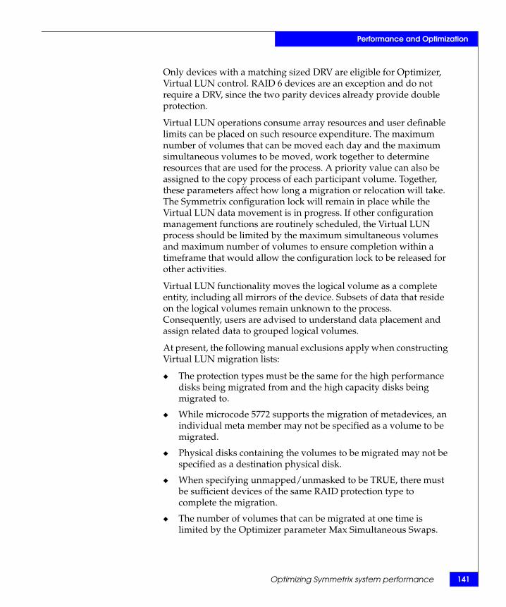
Performance and Optimization
Only devices with a matching sized DRV are eligible for Optimizer, Virtual LUN control. RAID 6 devices are an exception and do not require a DRV, since the two parity devices already provide double protection.
Virtual LUN operations consume array resources and user definable limits can be placed on such resource expenditure. The maximum number of volumes that can be moved each day and the maximum simultaneous volumes to be moved, work together to determine resources that are used for the process. A priority value can also be assigned to the copy process of each participant volume. Together, these parameters affect how long a migration or relocation will take. The Symmetrix configuration lock will remain in place while the Virtual LUN data movement is in progress. If other configuration management functions are routinely scheduled, the Virtual LUN process should be limited by the maximum simultaneous volumes and maximum number of volumes to ensure completion within a timeframe that would allow the configuration lock to be released for other activities.
Virtual LUN functionality moves the logical volume as a complete entity, including all mirrors of the device. Subsets of data that reside on the logical volumes remain unknown to the process. Consequently, users are advised to understand data placement and assign related data to grouped logical volumes.
At present, the following manual exclusions apply when constructing Virtual LUN migration lists:
◆ The protection types must be the same for the high performance disks being migrated from and the high capacity disks being migrated to.
◆ While microcode 5772 supports the migration of metadevices, an individual meta member may not be specified as a volume to be migrated.
◆ Physical disks containing the volumes to be migrated may not be specified as a destination physical disk.
◆ When specifying unmapped/unmasked to be TRUE, there must be sufficient devices of the same RAID protection type to complete the migration.
◆ The number of volumes that can be migrated at one time is limited by the Optimizer parameter Max Simultaneous Swaps.
Optimizing Symmetrix system performance 141

142
Performance and Optimization
The following sequence shows an example of the Symmetrix Management Console (SMC) three-step process to prepare a migration. The entry dialog box is available under the Optimizer > Swap/Move > Manual Move drop down sequence.
Figure 35 on page 142 shows step 1 of the SMC migration dialog box, selecting the devices. Devices are highlighted and moved to the Selected Devices list on the right hand side of the dialog box.
Figure 35 SMC migration dialog box step 1
EMC Symmetrix DMX-4 Product Guide

Performance and Optimization
Figure 36 on page 143 shows step 2 of the SMC migration dialog box, selecting the target disks. It is important to note that disks containing the source devices are excluded from the migration target disks.
Figure 36 SMC migration dialog box step 2
Optimizing Symmetrix system performance 143

144
Performance and Optimization
Figure 37 on page 144 shows step 3 of the SMC migration dialog box: scheduling the data move. The start of the Virtual LUN process can be scheduled in this SMC window, or it can start according to policies defined in the Optimizer program. Other Optimizer parameters, such as maximum simultaneous volumes, maximum number of volumes and priority, will affect the runtime of the Virtual LUN migration.
Note: “Symmetrix Optimizer” on page 153 contains additional information.
Figure 37 SMC migration dialog box step 3
EMC Symmetrix DMX-4 Product Guide

Performance and Optimization
Dynamic Host AddressingDynamic Host Addressing allows any device seen by any HBA to have any LUN number, by avoiding fixed LUN offsets. Dynamic Host Addressing is an enhancement to the VolumeLogix functionality to provide more flexibility of device addressing on Symmetrix ports.
VolumeLogix allows users to control which devices on a Symmetrix port are visible to which HBAs (using the HBA WWN). A previous feature of Volume Logix, LUN Offset, allowed the user to specify a single 'offset' for each HBA (for each Symmetrix port) that would be used to allow HBA's to have their own set of devices visible, starting at LUN address zero. This was particularly useful for HBA's that required the use of LUN addresses 0x00–0xFF. LUN Offset was limited in that it allowed only a single offset to be specified. Since the LUN address used by the host was directly associated with the address configured on the FA port, the flexibility of this feature was limited.
Dynamic Host Addressing provides maximum flexibility when configuring devices addresses, by removing any association between the host LUN address and the address given to the device on the FA port. The only requirement is that the device be mapped to the FA port. This feature allows any device to be configured for any LUN address on any originator (HBA) on any port. When configuring new storage or assigning devices to a port and originator, the user can either specify the LUN address that the HBA will use to access the device (for maximum control), or let the system find the next LUN address available for that HBA (if the user does not require control over specific LUN addresses).
Dynamic Host Addressing requires a new format of the records in the VolumeLogix database in the system. Moving to the new format will be done nondisruptively to the user and transparent overall. On the first provisioning action that specifies Dynamic Host Addressing should be used, the record containing the configuration information for the HBA/Symm port in question will be translated nondisruptively to the new format. Impact is transparent to the user. Records in both the old format and the Dynamic Addressing format can coexist in the system; translation is done only on those records that are being updated.
Dynamic Host Addressing is supported with SYMCLI version 6.4 and can be managed by Symmetrix Management Console (SMC).
Dynamic Host Addressing 145

146
Performance and Optimization
EMC Symmetrix DMX-4 Product Guide
Virtual Provisioning
Note: Refer to the Symmetrix DMX-3, DMX-4 Enginuity Release Notes and consult your local EMC Sales Representative for currently supported Virtual Provisioning features and availability.
This new Enginuity 5773 product enables open systems users to be granted what appear to be very large quantities of storage space, while the actual space consumed on physical disk storage is only that used by actual data being written. Virtual Provisioning can reduce the amount of allocated but unused storage for appropriate environments. Virtual Provisioning will support local and remote replication, including “thin to thin” replication with SRDF and TimeFinder. Virtual Provisioning can be set up and managed by Symmetrix Management Console (SMC) and SYMCLI. Virtual Provisioning can be purchased under a separate license from EMC.
Virtual Provisioning description
Virtual Provisioning provides for the separation of the physical storage devices from the storage devices as perceived by the host systems. The actual physical storage is not perceived by the host. This allows alterations in the physical storage to occur without causing changes which affect the hosts. The result is nondisruptive provisioning.
Virtual Provisioning has the ability to define to the host servers an apparent disk configuration that is far larger than current needs. It may be possible to provision an amount of storage for applications which will last the life of the applications themselves. This means applications need to be disrupted much less frequently to make changes or add storage.
Virtual Provisioning also means simplification of choices as to which volumes to use for which files. Whether these choices are made by people or software, the choices will be less often restricted by limited space. The choices made will more often reflect the needs of simplicity of management, or performance requirements.
Wide striping allows the data to be spread evenly across a broad pool. It allows all data in an application group, known in this case as a thin pool, to be spread fairly evenly across all the drives supporting that group. This balancing of the workload across physical devices can translate into improved performance. It can reduce queuing and smooth out response times. It also reduces performance management effort.
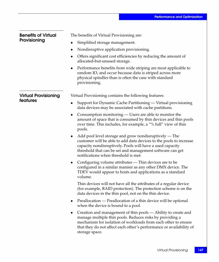
Performance and Optimization
Benefits of Virtual Provisioning
The benefits of Virtual Provisioning are:
◆ Simplified storage management.
◆ Nondisruptive application provisioning.
◆ Offers significant cost efficiencies by reducing the amount of allocated-but-unused storage.
◆ Performance benefits from wide striping are most applicable to random IO, and occur because data is striped across more physical spindles than is often the case with standard provisioning.
Virtual Provisioning features
Virtual Provisioning contains the following features:
◆ Support for Dynamic Cache Partitioning — Virtual provisioning data devices may be associated with cache partitions.
◆ Consumption monitoring — Users are able to monitor the amount of space that is consumed by thin devices and thin pools over time. This includes, for example, a “% full” view of thin pools.
◆ Add pool level storage and grow nondisruptively — The customer will be able to add data devices to the pools to increase capacity nondisruptively. Pools will have a used capacity threshold that can be set and management software can get notifications when threshold is met.
◆ Configuring volume attributes — Thin devices are to be configured in a similar manner as any other DMX device. The TDEV would appear to hosts and applications as a standard volume.
Thin devices will not have all the attributes of a regular device (for example, RAID protection). The protection scheme is on the data devices in the thin pool, not on the thin device.
◆ Preallocation — Preallocation of a thin device will be optional when the device is bound to a pool.
◆ Creation and management of thin pools — Ability to create and manage multiple thin pools. Reduces risks by providing a mechanism for isolation of workloads from each other to ensure that they do not affect each other’s performance or availability of storage space.
Virtual Provisioning 147
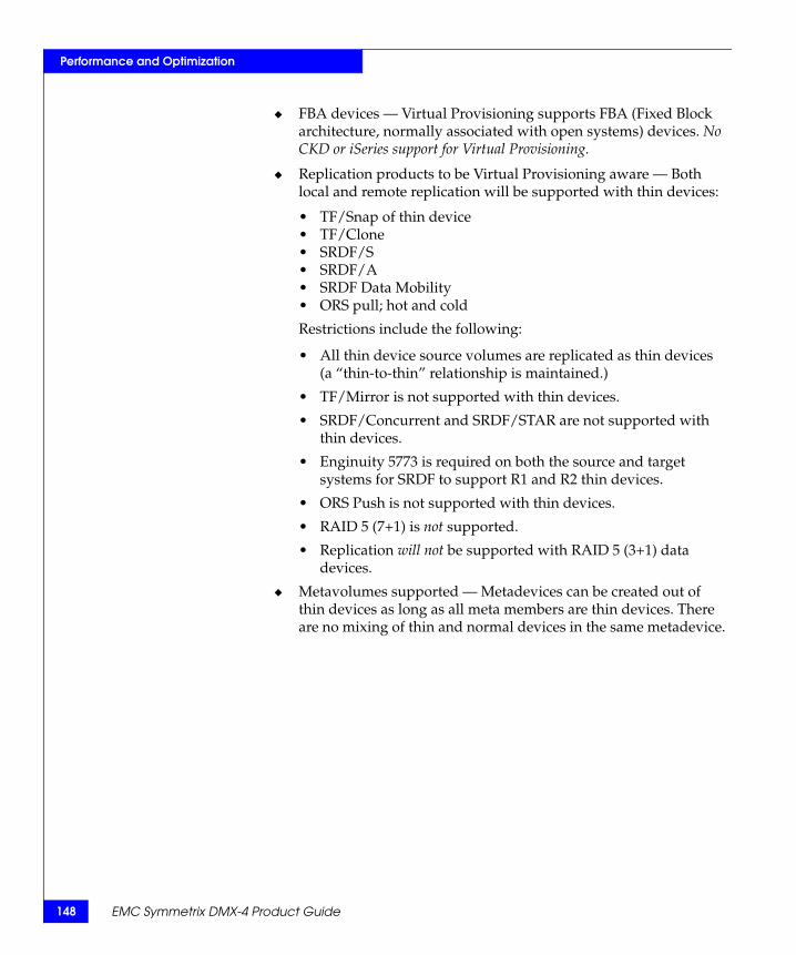
148
Performance and Optimization
◆ FBA devices — Virtual Provisioning supports FBA (Fixed Block architecture, normally associated with open systems) devices. No CKD or iSeries support for Virtual Provisioning.
◆ Replication products to be Virtual Provisioning aware — Both local and remote replication will be supported with thin devices:
• TF/Snap of thin device• TF/Clone• SRDF/S• SRDF/A• SRDF Data Mobility• ORS pull; hot and cold
Restrictions include the following:
• All thin device source volumes are replicated as thin devices(a “thin-to-thin” relationship is maintained.)
• TF/Mirror is not supported with thin devices.
• SRDF/Concurrent and SRDF/STAR are not supported with thin devices.
• Enginuity 5773 is required on both the source and target systems for SRDF to support R1 and R2 thin devices.
• ORS Push is not supported with thin devices.
• RAID 5 (7+1) is not supported.
• Replication will not be supported with RAID 5 (3+1) data devices.
◆ Metavolumes supported — Metadevices can be created out of thin devices as long as all meta members are thin devices. There are no mixing of thin and normal devices in the same metadevice.
EMC Symmetrix DMX-4 Product Guide

49
Performance and Optimization
Multiport volume access for open systems environments 1
Multiport volume access for open systems environmentsUnlike most disk arrays, the Symmetrix system can present any logical volume through any number of Fibre Channel channels to the hosts connected to the system. Usually, a Symmetrix volume will be presented through one host channel. However, in different failover or cluster scenarios, the volume will be visible to different hosts on two or more Fibre Channel channels.
For example:
◆ A volume may be configured to be visible on two channels for host channel failover (such as EMC PowerPath® or HP-UX PV links).
◆ A volume can be accessed by up to 32 separate paths using EMC PowerPath.
◆ A volume can be configured to be visible on one channel for a hot standby scenario where one host can assume the devices of another host in case of a controller or host failure.
◆ A volume can be visible through all channels in cluster environments that can take advantage of such multiport volume access (such as NCR Teradata).
Note: For more information on multiport volume access, and the most current information on Symmetrix systems and specific host integration, contact your local EMC Sales Representative, or refer to the EMC Powerlink website.
150
Performance and Optimization
Software options overviewThe following software options are described in these sections:
◆ “EMC ControlCenter family of products” on page 150◆ “Symmetrix Optimizer” on page 153◆ “TimeFinder family of products” on page 154◆ “Solutions Enabler” on page 155◆ “Symmetrix Management Console” on page 155
EMC ControlCenter family of products
EMC ControlCenter is a family of products that provides you with an integrated approach to managing your multivendor storage environment, and automating many of your common storage management tasks. The ControlCenter base product is comprised of Open Integration Components (OIC). Several other ControlCenter plug-in products are available. The ControlCenter products you choose depend on the Storage Resource Management (SRM) solutions you want to implement.
This EMC ControlCenter section contains many references to supporting publications, which can be accessed from any of the following:
◆ Documentation/Help CD provided with your EMC ControlCenter installation kit
◆ EMC Powerlink at http://Powerlink.EMC.com
◆ ControlCenter Documentation Library, which is available from the ControlCenter Console’s help menu after installation.
Open integrationcomponents
At the heart of ControlCenter is a common foundation and infrastructure, which provides scalability, usability, and information sharing across all ControlCenter applications. An embedded database stores and shares information about each object being managed. Common services, part of OIC, discover, correlate, and map relationships between objects.
This design enables ControlCenter applications, such as Symmetrix Manager and Performance Manager, to span storage array, storage network, and host management functions.
EMC Symmetrix DMX-4 Product Guide

Performance and Optimization
OIC components include:
◆ User interfaces:
• E Web Console
◆ Infrastructure:
• ECC Server• Repository• Store
◆ Agents:
• Host agents for Solaris, HP-UX, AIX, Linux, and Windows• Common Mapping Agent• Database Agent for Oracle• Database Agent for DB2• Integration Gateway Agent• Physical agent for z/OS• Storage Agent for SMI
◆ Common services
Common services span across all ControlCenter applications providing you with simple access to various tasks and to the various views of your SAN and the objects in it. These common services allow you to discover and monitor objects in your SAN.
For example, you can map the relationship of storage structures from databases and file systems through to their logical and physical location within the storage array. Common services also provides you with information such as the status of your environment, high-level perspective on performance, capacity, and health.
Common services include:
◆ Administration services:
• Security management• Agent configuration
◆ Console views include:
• Topology view• Relationship view• Properties view• Performance view• Alerts view• Command History
Software options overview 151

152
Performance and Optimization
Storage resourcemanagement
solutions
In addition to the base functionality provided by OIC, several other ControlCenter products are available. ControlCenter product packaging is based on the storage resource management (SRM) solutions that follow.
SRM planning and provisioningThe planning and provisioning solution allows you to design, plan, and provision a multivendor storage infrastructure for the benefit of improving the utilization, performance, and cost effectiveness of your storage assets. It also allows you to quickly recognize, isolate, and respond to storage issues from a single console.
This solution is achieved using the following ControlCenter applications:
◆ SAN ManagerTM
◆ SAN AdvisorTM
◆ Automated Resource ManagerTM
SRM monitoring and reportingThe monitoring and reporting solution allows you to effectively utilize your storage assets, manage inventory, and assess how your storage is performing.
This solution is achieved using the following ControlCenter applications:
◆ Performance Manager
◆ StorageScopeTM
◆ StorageScope File Level Reporter
SRM storage device managementThe storage device management solution allows you to actively configure and optimize storage arrays.
This solution is achieved using the following ControlCenter applications:
◆ Symmetrix Manager
◆ Symmetrix Optimizer
EMC Symmetrix DMX-4 Product Guide

Performance and Optimization
Symmetrix Optimizer
Symmetrix Optimizer helps you increase the performance of a Symmetrix system by spreading I/O activity evenly across the physical disks. When a particular drive is in high demand, there is excessive head movement on that drive. This movement slows down read and write activity. By balancing highly active and less active logical devices across drives, seek activity is balanced, and contention among drives is reduced. Throughput within the overall Symmetrix system is improved, and you experience optimal response times.
Optimizer performs self-tuning of Symmetrix data configurations from the Symmetrix service processor by:
◆ Analyzing statistics about Symmetrix logical device activity.
◆ Determining which logical devices should have their physical locations swapped to enhance Symmetrix performance.
◆ Swapping logical devices and their data using internal Dynamic Reallocation Volumes (DRVs) to hold customer data while reconfiguring the system (on a device-to-device basis).
How SymmetrixOptimizer works
Symmetrix Optimizer:
◆ Automatically collects logical device activity data, based upon the devices and time window you define.
◆ Identifies “hot” and “cold” logical devices, and determines on which physical drives they reside.
◆ Compares physical drive performance characteristics, such as spindle speed, head actuator speed, and drive geometry.
◆ Determines which logical device swaps would reduce physical drive contention and minimize average disk service times.
◆ Using the Optimizer Swap Wizard, swaps logical devices to balance activity across the back end of the Symmetrix array.
Optimizer is designed to run automatically in the background, analyzing performance in the performance time windows you specify and performing swaps in the swap time windows you specify.
Software options overview 153
154
Performance and Optimization
EMC Symmetrix DMX-4 Product Guide
TimeFinder family of products
The TimeFinder family of software is the most powerful suite of local storage replication solutions available, delivering a wide range of in-the-system data copying capabilities to meet mixed service level requirements without operational impact.
Use the TimeFinder family to:
◆ Create instantly accessible business continuance volumes (BCVs): mirrors, clones, and snapshots.
◆ Perform backups quickly, frequently, and without disruption.
◆ Reduce time limitations through workload compression.
◆ Eliminate job-step copies to improve batch processing time.
◆ Seamlessly load or update data warehouses as needed.
◆ Provide production data for application development testing without scheduling downtime.
The TimeFinder family includes the following products:
◆ TimeFinder family base products:
• TimeFinder/Clone
Highly functional, high performance full volume, point-in-time BCVs for backups, online restores, and volume migrations.
• TimeFinder/Snap
Pointer-based, economical, space-saving snapshots of BCvs for reduced recovery points and fast local data restore.
◆ TimeFinder family add-on options:
• TimeFinder/Mirror
Highly available, ultra-performance mirror BCV option for the most demanding environments.
• TimeFinder/Consistency Groups
Maintain data coherency across TimeFinder-protected application volumes to ensure data consistency and restartability.
• TimeFinder/Exchange Integration Module and TimeFinder SQL integration Module
Tight integration of the TimeFinder family with Microsoft Exchange and SQL applications for automated backup and restore.

55
Performance and Optimization
Software options overview 1
Solutions Enabler In order to retrieve data from a Symmetrix system and information about databases and file systems that are to be monitored by certain ControlCenter agents, such as Common Mapping Agent, you must install the EMC Solutions Enabler on the host managing the Symmetrix system (either the host running the Storage Agent for Symmetrix or a proxy host.
Solutions Enabler provides low-level SCSI commands that communicate with Symmetrix systems to retrieve configuration, status, and performance information.
When you install Solutions Enabler, you are installing these components:
◆ SYMMAPI — The Symmetrix Application Programming Interface and runtime libraries.
◆ SYMCLI — An open systems application, written using the SYMAPI, that manages Symmetrix systems.
◆ SYMAPI Server — A process that retrieves status and performance information by polling the Symmetrix systems and processing client commands.
Symmetrix Management Console
Symmetrix Management Console (SMC) is an intuitive, browser-based graphical user interface for managing Symmetrix systems. It can be hosted on a small Windows server and accessed using a customer’s Web browser. Symmetrix Management Console is a graphical complement to CLI (command line interface) usage and to full EMC ControlCenter SRM capabilities when customers need to perform device management of a Symmetrix system. Symmetrix Management Console is now bundled with ControlCenter Symmetrix Manager and available to Symmetrix Manager customers with active maintenance contracts at no extra charge.
SMC accelerates FBA and CKD device management tasks, for example, enabling administrators to configure or replicate devices with a few clicks and keystrokes and to duplicate devices with simple templates containing device attributes such as capacity, configuration, and emulation type. SMC provides realtime monitoring and alerting on system health, director and drive status, and SRDF/A replication operations (looking at such metrics as cache utilization and cycle time).

156
Performance and Optimization
SMC also provides intuitive control and monitoring for tiered storage optimization software, including Symmetrix Optimizer Virtual LUN technology, Symmetrix Priority Controls, and Dynamic Cache Partitioning. SMC security features include user authentication, restricted user roles, management of Symmetrix Access Controls, and management of the Symmetrix Audit Log.
EMC Symmetrix DMX-4 Product Guide

5Invisible Body Tag
This chapter discusses the Symmetrix DMX-4 features and options that affect data availability and reliability:
◆ Overview........................................................................................... 158◆ Reliability and availability features............................................... 162◆ Maintaining data integrity.............................................................. 175◆ DMX-4 security features ................................................................. 181◆ Data protection guidelines.............................................................. 189◆ Disk mirroring (RAID 1) concepts................................................. 191◆ Symmetrix RAID 1/0 for open systems ....................................... 195◆ Symmetrix RAID 10 for mainframe systems ............................... 196◆ Symmetrix DMX RAID 5 ................................................................ 198◆ Symmetrix DMX RAID 6 ................................................................ 206◆ Sparing in Symmetrix systems....................................................... 211◆ SRDF family of products................................................................. 219
Data Integrity,Availability, and
Protection
Data Integrity, Availability, and Protection 157

158
Data Integrity, Availability, and Protection
OverviewThe Symmetrix system has many features and options to ensure a high degree of system and data availability. Many of these features and options are built into the Symmetrix design. Other availability options may be purchased separately and implemented into the Symmetrix system operation.
Symmetrix reliability and availability features
The Symmetrix system design offers the following reliability and availability features:
◆ High-reliability components◆ Global memory director redundancy◆ Redundant global memory◆ Channel director redundancy◆ Redundant internal data paths◆ Internal control data path redundancy◆ Fibre Channel back-end redundancy◆ Dual-Initiator feature◆ Redundant power subsystem◆ Vaulting◆ System battery backup◆ Nondisruptive maintenance and microcode upgrades and loads
These basic Symmetrix features provide protection against loss of system and data availability due to a power loss or failed component. A redundant design allows the Symmetrix system to remain online and operational during component repair. For example, if a power supply fails, the remaining power supplies share the load until the failed component is replaced. The system battery backup prevents any loss of data due to a power failure.
Symmetrix data integrity protection features
The Symmetrix system is designed with these data integrity features:
◆ Error checking, correction, and data integrity protection◆ Disk error correction and error verification◆ Global memory error correction and error verification◆ Periodic system checks
Error verification prevents temporary errors from accumulating and resulting in permanent data loss. Symmetrix systems also evaluate the error verification frequency as a signal of a potentially failing component.
EMC Symmetrix DMX-4 Product Guide

Data Integrity, Availability, and Protection
The periodic system check tests all components as well as microcode integrity. Symmetrix systems report errors and environmental conditions to the host system as well as the EMC Customer Support Center.
Data protection options
Although the Symmetrix system has standard features that provide a higher level of data availability than conventional DASD, the options described in this section ensure an even greater level of data recoverability and availability. These data protection options are configurable at the physical volume level so that different levels of protection can be applied to different datasets within the same Symmetrix system.
Working with your local EMC Sales Representative, you can choose from the following Symmetrix data protection options to match your critical data requirements:
◆ “Mirroring (RAID 1)” on page 159◆ “RAID 1/0” on page 160◆ “RAID 10” on page 160◆ “RAID 5” on page 160◆ “RAID 6” on page 160◆ “Symmetrix Remote Data Facility (SRDF)” on page 161◆ “Permanent sparing” on page 212◆ “Dynamic sparing” on page 215
Mirroring (RAID 1) Mirroring (RAID 1) provides the highest performance, availability, and functionality for all mission-critical and business-critical applications. With the Mirroring option, Symmetrix systems maintain two identical copies of a logical volume on separate drives. Should the Symmetrix system be unable to read data from one of a mirrored pair, it immediately retrieves the data from the other logical volume.
Note: “Disk mirroring (RAID 1) concepts” on page 191 provides more information on the Symmetrix Mirroring option.
Overview 159
160
Data Integrity, Availability, and Protection
EMC Symmetrix DMX-4 Product Guide
RAID 1/0 RAID 1/0 is a combination of RAID 1 and RAID 0 for open systems environments. Data is striped across mirrored pairs.
Note: “Symmetrix RAID 1/0 for open systems” on page 195 provides additional information.
RAID 10 RAID 10 is a combination of RAID 1 and RAID 0 for the mainframe environment. Data is striped across mirrored pairs.
Note: “Symmetrix RAID 10 for mainframe systems” on page 196 provides additional information.
RAID 5 The Symmetrix DMX-4 supports RAID 5 data protection. This is an implementation of the industry-standard RAID 5 data-protection technique with rotating parity across all members of the RAID 5 set.
RAID 5 provides cost-effective data protection against drive failure. While the most demanding environments continue to opt for mirrored storage for maximum performance, RAID 5 offers an extremely attractive alternative for information storage where price is more important than performance.
For Symmetrix DMX, RAID 5 is available in one of two configurations per array, RAID 5 (3+1) or RAID 5 (7+1), in which data and parity are striped across four or eight physical disks, respectively.
RAID 5 offers Symmetrix DMX-4 customers the benefits of:
◆ Symmetrix Optimizer supports RAID 5 devices.
◆ RAID 5 devices can be used with Dynamic SRDF and PPRC.
◆ RAID 5 devices require only one spare drive.
Note: “Symmetrix DMX RAID 5” on page 198 provides additional information.
RAID 6 RAID 6 is defined as any configuration that supports more than a single disk drive failure. Similar to RAID 5 devices, the data blocks are striped/interleaved across all members of the RAID group. RAID 6 uses permanent sparing. If no spare is found in a good location, then dynamic sparing is invoked.
For Symmetrix DMX, RAID 6 is available in one of two configurations per array, RAID 6 (6+2) or RAID 6 (14+2), in which data and parity are striped across 8 or 16 physical disks, respectively.

61
Data Integrity, Availability, and Protection
Overview 1
Symmetrix RemoteData Facility (SRDF)
Note: The “SRDF family of products” on page 219 contains additional information on SRDF applications.
EMC’s SRDF family of software products help companies manage planned data center events such as scheduled maintenance, daily backups, migrations, and application testing, as well as recovery from unplanned outages such as disasters. The following sections briefly describe the SRDF product offerings.
Note: Each of the SRDF product offerings is sold under a separate license by EMC. EMC Symmetrix Remote Data Facility (SRDF) Product Guide contains more in-depth information about SRDF. Contact your local EMC Sales Representative for specific information on availability of each of the SRDF products.
Permanent sparing Permanent sparing is an automatic data protection option for all Symmetrix DMX-4 systems. It is used in conjunction with mirroring, RAID 5, RAID 6, or SRDF. The permanent sparing process identifies an identical drive in a good location and begins to move the data to the new drive. If there is no drive available in a good location, the dynamic sparing process is followed.
After the permanent sparing process completes, all system features are available, and the Symmetrix returns to normal operation without waiting for a CE to replace the failed drive. The failed drive is left as a not ready drive. When the failed drive is replaced, the CE issues commands for the Symmetrix system to place the drive in the spare pool, making it available should another volume fail in the future.
Note: “Permanent sparing” on page 212 provides more information on the permanent sparing option.
Dynamic sparing Dynamic sparing is a data protection option for all Symmetrix DMX-4 systems. It is used in conjunction with mirroring, RAID 5, or SRDF. (Dynamic sparing cannot be used with RAID 6.) If permanent sparing cannot be used, then dynamic sparing is invoked. Dynamic sparing limits the exposure after drive failure and before drive replacement. With dynamic sparing, the Symmetrix system maintains a pool of spare drives that are used only when the system detects a potentially failing device. The dynamic sparing process moves the data and uses the spare until the original device can be replaced.
Note: Contact your local EMC Sales Representative for specific Dynamic sparing configuration rules. “Dynamic sparing” on page 215 contains additional information.

162
Data Integrity, Availability, and Protection
Reliability and availability featuresSymmetrix systems have several features that allow them to maintain data integrity and maximize system availability. This section discusses several features in detail.
Reliable components
Symmetrix systems use components that have a mean time between failure (MTBF) of several hundred thousand to millions of hours for a minimal component failure rate. A redundant design allows Symmetrix systems to remain online and operational during component repair.
A periodic system check tests all components as well as microcode integrity. Symmetrix systems report errors and environmental conditions to the host system as well as the EMC Customer Support Center.
Global memory director data integrity
Every Symmetrix system is configured with a minimum of two global memory directors to allow for online nondisruptive replacement of a failing global memory director. When a hard error is detected, or temporary errors reach a predetermined threshold, the Symmetrix service processor calls home to request an immediate maintenance action.
Note: “Maintaining data integrity” on page 175 provides more information on global memory director data integrity protection.
Redundant global memory
Symmetrix DMX-4 global memory director operations are redundant by way of a primary and secondary global memory director working as a pair. If an error is detected in one of the memory directors, no writes are allowed to the board containing the error. The writes will be made to the nonfailing memory director until the failed global memory director is replaced. The remaining good memory director remains unprotected until a memory director replacement is performed on the failed memory director. When the new memory director is installed, Global Services personnel perform a copy back from the good remaining director to the newly installed director. This ensures that both memory directors are completely synchronized in the Symmetrix DMX-4 system.
EMC Symmetrix DMX-4 Product Guide

Data Integrity, Availability, and Protection
Channel director redundancy
Channel director redundancy is provided by configuring multiple connections from the host servers (direct connect) or Fibre Channel switch (SAN Connect) to the Symmetrix system. With SAN connectivity, through Fibre Channel switches, each Symmetrix DMX-4 port can support multiple host attachments, enabling storage consolidation across a large number of host platforms. The multiple connections are distributed across separate channel directors to ensure uninterrupted access in the event of a channel failure. A minimum of two connections per server or SAN is required to provide full redundancy. Table 27 on page 163 defines the number of host/SAN connections available for the Symmetrix DMX-4 system.
Channel failover functionality is required to automate the failover and fail back process to avoid an interruption to data access.
Without this functionality, a path failure due to a problem with the host bus adapter, Fibre Channel switch, fibre cable, or channel director would create the potential for the application to go down. EMC PowerPath provides this functionality and supports end-to-end, (host-to-switch and switch-to-storage) channel failover functionality. PowerPath provides automatic, nondisruptive failover capabilities by redirecting I/Os from a failed channel to all remaining channels for open systems devices. PowerPath can automatically detect when a path has failed and sends an error log to the host to notify it that there is an inactive path.
Table 27 Symmetrix DMX-4 channel director connectivity
Protocol a Usable system ports b Ports per channel director
4 Gb/s Fibre Channel Host/SAN ports 2-64 1-8 per Fibre Channel Director
2 Gb/s Fibre Channel remote replication ports 2-8 1-4 per Fibre Channel Director
1 Gb/s iSCSI ports 2-32 1-4 per Multiprotocol Channel Director
1 Gb/s GigE remote replication ports 2-8 1-4 per Multiprotocol Channel Director
1 Gb/s GigE IPv4/v6 (IPsec capable) 2-8 1-4 per Multiprotocol Channel Director
4 Gb/s FICON host ports 2-32 1-4 per Multiprotocol Channel Director
ESCON host ports 2-80 1-8 per ESCON Director
ESCON remote replication ports 2-8 1-8 per ESCON Director
a. Contact your local EMC Sales Representative for ESCON channel director and GigE Remote support availability.b. Usable ports are per qualified channel directors.
Reliability and availability features 163
164
Data Integrity, Availability, and Protection
PowerPath then fails over the existing I/O request to another active path to maintain data access and application availability—offering intelligent load-balancing capabilities to optimize performance and minimize bottlenecks. All this occurs transparently to the host so the application is not stopped and data is continuously available. Once the failed path is fixed or repaired, PowerPath automatically detects activity, brings the path back into operation, and automatically sends I/O requests down to the now-active path. The major benefits of the path failover capability is the ability to automatically detect a channel failure, transparently redirect an I/O to other available channels, and easily service and restore the failed channel without interrupting applications.
Internal control data path redundancy
Each director has two paths to connect the Symmetrix DMX message matrix between each director. Independent and redundant fault domains are provided by a plug-in Communications and Environmental Control Module (XCM). These fault domains within the message matrix fabric are intelligent at the hardware level and load balance traffic between each domain. In the event that a fault occurs within one of the domains, the traffic is automatically routed by the hardware to the available domain, and the system is alerted of the faulty XCM domain for replacement. The connection is made through the plug-in XCM.
There are two XCMs per system. If we look at a fully configured Symmetrix DMX, for example, 16 directors are configured with 32 point-to-point serial connections. This means 16 connections are routed to the first XCM and the other 16 redundant connections are routed to the second XCM. The message engine (ME) component of the message matrix provides protection against rogue or runaway nodes. This is done at each message engine through error correction coding configurations, allowing the nodes to receive messages. Packet CRC and sequence numbers protect each message packet transmitted. Internal data paths with the message engine and fabric element are fully parity protected.
Fibre Channel back-end redundancy
The Symmetrix DMX architecture incorporates a 4 Gb/s Fibre Channel back-end design to ensure high performance and full redundancy. The Fibre Channel back-end disk subsystem provides redundant paths to the data stored on the disk drives to provide nonstop access to information, even in the event of a component failure or replacement. The following is an overview of the redundant components of the Symmetrix DMX back-end disk subsystem.
EMC Symmetrix DMX-4 Product Guide

Data Integrity, Availability, and Protection
Redundant diskdirectors
A pair of directors is used to access each disk drive. One director is connected to one physical path to the drive, and the other director is connected to a second physical path to the drive. The directors are responsible for moving data between the global memory and the disks and, as such, are each connected to the global memory through redundant internal paths, to eliminate any possible single points of failure.
Redundant cablepaths
Each disk director is attached to its associated set of Fibre Channel disks by a separate, independent cable assembly that carries the Fibre Channel loop, control bus, and other protocol signals.
Redundant disk ports Each Fibre Channel disk drive has two fully independent Fibre Channel ports that are designed to connect to two separate loops. In the Symmetrix DMX architecture, these two ports are each connected to a different link control card (LCC), which in turn is connected through separate cables to two different disk directors. These two pathways are completely independent of one another.
Fibre Channel arbitrated loop design
Symmetrix DMX systems employ an arbitrated loop design that contains monitoring and control hardware and software to maximize the performance and availability of each loop. The loop is connected in a Star-Hub topology, with the hub ports gated with a bypass switch that allows individual loop segments (that connect to a Fibre Channel disk drive) to be dynamically inserted or removed. The loop initiator is a Symmetrix Fibre Channel disk director, which feeds data into and controls the hub. All of the monitoring and control logic is contained on the link control card, which also contains the bypass/hub logic for the loop. To ensure the highest level of availability, the communications link to the monitoring and control functions is not carried by the Fibre Channel loop—but, rather is implemented through a separate path. If the Fibre Channel loop is not operating for some reason, the director can access the LCC through the control bus and reconfigure the loop into a working state.
Link control cards The LCC is the heart of the Symmetrix DMX-4 disk Fibre Channel loop. The LCC’s functions are to provide Fibre Channel Data Connectivity to disk drives as well as the capability to control functionality and monitor environmental status. The LCC constantly monitors the loop for Fibre Channel layer 0/1 signal connection and protocol errors. If errors are detected, the controlling software program is notified and, if necessary, the bypass circuits may be used to switch out the failing loop segment, thereby allowing the remaining devices on the loop to operate unaffected.
Reliability and availability features 165

166
Data Integrity, Availability, and Protection
Each disk enclosure, which contains up to 15 individual disk drives, contains a pair of LCCs. Each LCC uses FC_AL protocols to emulate a loop; it connects one of the ports of the 15 drives to a disk director in a point-to-point fashion. For each disk connection, a bypass circuit is provided and allows that disk connection to be shunted. This only occurs when the drive is not installed, the drive was just powered on, the drive was reset, or the drive is malfunctioning. In addition to the bypass circuits themselves, the card contains multiple real-time monitors embedded within the loop that can determine if bad data is being generated on the loop. These monitors report status to the loop control software and can be useful in isolating potential hardware failures. The LCC also has the ability to control power to the drives, and it maintains basic configuration information so that if the loop configuration is changed (a new disk assembly is inserted, for example), it reports this to the control software program so that it may take the appropriate action. The LCC is located within the disk enclosures, which allows replacement in the case that the isolation device itself fails. Each port of a disk is connected to a different LCC (A or B), so access to the data is maintained even during service operations.
Point-to-pointback-end
Symmetrix DMX-4 systems employ a point-to-point back-end that contains monitoring and control hardware and software to maximize the performance and availability of each loop. The back-end has an independent relationship with each drive on the loop to speed problem isolation and improve serviceability. This dedicated relationship between a back-end controller and each disk drive also allows Symmetrix DMX-4 to analyze drive health prior to adding new disks to an existing configuration. Symmetrix DMX-4 will not add a faulty drive to an existing loop. The loop initiator is a Symmetrix Fibre Channel disk director, which feeds data into and controls the loop. All of the monitoring and control logic is contained on the Link Controller Card (LCC). To ensure the highest level of availability, the communications link to the monitoring and control functions is not carried by the Fibre Channel loop—but, rather is implemented through a separate path. If the Fibre Channel loop is not operating, the director can access the LCC through the “out-of-band” control path and reconfigure the loop into a working state. While the control path utilizes the Fibre Channel signals, it is not dependant on the operation of the Fibre Channel interconnect.
Figure 38 on page 167 is an illustration of the back-end redundancy of the Symmetrix DMX-4 system.
EMC Symmetrix DMX-4 Product Guide

Data Integrity, Availability, and Protection
Figure 38 Fibre Channel back-end redundancy
Data integrity for FibreChannel arbitrated
loops
In order to ensure that the data transmitted by the disk director is the same as the data received by the disk drive, a multilayer protection strategy is employed. At the highest level, as data is transmitted between the global memory and the disk, a connection referred to as an exchange is established.
Logical parameters that identify this connection are initialized, and then all information transferred as part of this exchange is identified with these parameters. In addition, as the data in global memory is encapsulated into Fibre Channel frames, it is marked with a sequence number that identifies the order of the frame within the exchange and, in addition, a cyclic redundancy checksum is computed over the data and appended to the data frame. The receiving port (after validating the exchange parameters) will recompute the checksum for the data received and compare it to the transmitted checksum to determine if there are any bytes-in-error. It will also check the sequence number to ensure that the received frame is the next one expected for that exchange.
The next level of protection is designed in at the transmission layer of the Fibre Channel protocol. The data frame, with the additional information appended, is translated into special 10-bit data transmission symbols. These symbols are chosen for their ability to increase the reliability of the transmitted data, whether it is through a fiber-optic or copper cable.
LCC B LCC A SYM-000422
Reliability and availability features 167

168
Data Integrity, Availability, and Protection
The transmission codes also help to assist in detecting errors in transmission. Finally, once the data has been received at the disk drive (for writes) and decoded from the transmission codes, it will then be further recoded using a very powerful linear block coding algorithm before being stored on the disk’s magnetic surface. This code has the ability to not only detect errors, but to also correct them on the fly—ensuring that the data read from the drive at a later time will be read perfectly.
Dual-initiator feature
Symmetrix DMX systems have a dual-initiator feature that ensures continuous availability of data in the unlikely event of a Symmetrix disk management hardware failure. The dual-initiator feature does not provide data availability in the event of a disk drive failure. This feature works by having each of the four processors on the paired disk directors shadow each other’s functions. For example, this feature gives each processor the capability of servicing any or all of the devices of the processor with which it is paired, should one of the processors be unable to partially or fully service its own devices.
With the dual-initiator feature, for example, each of the four processors and its LCC of Disk Director 1 is paired with a LCC and a processor of Disk Director 16 (Figure 39 on page 169). Under normal conditions, each disk director processor services its own drives.
If the sophisticated fencing mechanisms of the Symmetrix system detect a failure on the disk director, the system reads from or writes to the drives through the disk director processor’s shadowed alternate path without interruption, and then notifies the EMC Customer Support Center. When the source of the failure is corrected, the Symmetrix system returns the I/O servicing of the two disk director processors to their normal state.
EMC Symmetrix DMX-4 Product Guide

Data Integrity, Availability, and Protection
Figure 39 Symmetrix DMX dual-initiator example
Redundant power subsystem
The Symmetrix DMX-4 has a modular power subsystem featuring a redundant architecture that facilitates field replacement of any of its components without any interruption in processing. The Symmetrix DMX system power subsystem has two power zones for redundancy and drive expansion. The DMX system connects to two dedicated or isolated AC power lines. If AC power fails on one line, the power subsystem continues to operate through the other power zone. If any Symmetrix DMX-4 single power supply module fails, the remaining power supplies continue to share the load. The Symmetrix DMX senses the fault and reports it as an environmental error.
Vaulting As cache size, disk size, and power requirements have grown, the time required to destage data has also increased. Vaulting is designed to limit the time needed to power off the system if it needs to switch to a battery supply. The vault image is fully redundant, with the specified contents of global memory being saved twice to independent disks.
4 to 15 disks drives per loop
Disk director 1
Disk director 16
Reliability and availability features 169

170
Data Integrity, Availability, and Protection
Powerdown operation When a DMX-4 is powered down, transitioned to offline, or when environmental conditions trigger a vault situation, a vaulting procedure is initiated. During powerdown or power loss, the part of global memory being saved first reaches a consistent image (no more writes). The disk directors then write the appropriate sections of global memory to disk, saving two copies of the logical data. The BBU modules maintain power to the system during the powerdown process for up to five minutes.
Powerup operation During power up, the data is written back to global memory to restore the system. When the Symmetrix system is powered on, the startup program does the following:
◆ Initializes the hardware and the environmental system.◆ Restores the global memory from the saved data while checking
the integrity of the data.◆ Performs clean-up, data structure integrity, and re-initialization of
needed global memory data structures.
At the end of startup program, the system resumes normal operation when the BBU are recharged enough to support another vault. If any condition is not safe, the system will not resume operation and will call Customer Support for diagnosis and repair. In this state, Customer Support will be able to communicate with the Symmetrix system and find out the reason for not resuming normal operation.
Note: Flash drives cannot be used as vault devices.
Power loss to one power zone
The Symmetrix power subsystem two-zone design (A, B) ensures that if there is an AC power loss to one of the zones, power from the second power source will maintain power to the affected bay or bays, provided that each system bay’s or storage bay’s two PDPs are connected to two separate source PDUs at the customer’s site. Upon an AC power loss to a single power zone, the system will maintain operation.
Power Zone Task Symmwin has a Power Zone Task which is disabled by default. The Power Zone Task is optional under normal operation, however it is highly recommended and considered best practice to disable the task before beginning any power- related maintenance on the system or site. The task setting can be modified in the Symmetrix Site Configuration window. An online configuration change is not required to change this setting.
EMC Symmetrix DMX-4 Product Guide

Data Integrity, Availability, and Protection
When the Power Zone Task is enabled and the system loses AC power to a single power zone, a 20-hour timer is invoked. The system will call home to notify the EMC Customer Support Center of the event. When the timer counts down to five hours the system will again call home. Before the 20-hour period ends, the EMC customer engineer can choose one of three options:
◆ Repair the cause of the power fault.
◆ Reset the 20-hour timer to continue the single power zone operation.
◆ Allow the system to vault, shutting down the system in an orderly manner.
Battery backup units (BBU)
The BBU modules ensure data integrity during power outages. The BBU modules provides the means for vaulting fast-write data that might be in global memory if AC power is lost on both lines to the unit. In addition to providing nonvolatility to the Symmetrix system, the BBU modules are fully capable of powering not only all electronic components, but also all HDAs during this time. This capability eliminates emergency power off situations, meaning that the disks are always powered down in an orderly manner, extending their useful life considerably.
The BBU modules allow the Symmetrix system to remain online to the host system in the event of an AC power loss. The BBU modules switch to battery power when the Symmetrix system detects loss of AC power. The BBU modules will maintain power to the Symmetrix system for up to five minutes while the global memory is vaulted to the vault disk drives.
The BBU modules also prevent disk drive failures due to the sharp power drops that occur during unexpected power interrupts. The BBU modules have sufficient capacity to ride out multiple AC outages, however it requires up to eight hours of uninterrupted recharge time to fully recharge the BBU modules. The BBU modules also contain a self-diagnostic controller to ensure availability and correct operation by monitoring the battery condition, charger states, and by providing status updates to the Communications and Environmental Control Module (XCM).
Reliability and availability features 171

172
Data Integrity, Availability, and Protection
Symmetrix powerfailure on mainframe
channels
When a power failure occurs, all directors send a unit check status with the environmental data-present bit set to all channels (error code 047A). Power switches immediately to the backup battery, and the Symmetrix system continues to operate normally. When the battery timer window elapses, the Symmetrix system presents SCU busy to prevent the host system from writing or reading any data at the unit.
The Symmetrix system destages any fast write data still in global memory to disk, spins down the drives and retracts the heads, and powers down, turning off the battery at that time. The Symmetrix system will respond not operational to the host after it powers down.
Symmetrix powerfailure on open
systems channels
When a power failure occurs, power switches immediately to the BBU modules and the Symmetrix system continues to operate normally. When the battery timer window elapses, the Symmetrix system presents a busy status to prevent the host system from writing or reading any data at the unit. The Symmetrix system destages any Fast Write data still in global memory to disk, spins down the drives and retracts the heads, and powers down, turning off the battery at that time. The Symmetrix system will not respond to SCSI commands after it powers down.
Nondisruptive component replacement
Symmetrix DMX systems implement a modular design with a low parts count that improves serviceability by allowing nondisruptive component replacement, should a failure occur. The low parts count minimizes the number of failure points. The Symmetrix DMX features concurrent maintenance of all major components, including:
◆ Channel directors◆ Disk directors◆ Global memory directors◆ Disk adapters◆ Channel adapters◆ Disk drives◆ Cooling fan modules◆ Communications and Environmental Control (XCM) modules◆ Power supplies ◆ Power Distribution Units (PDU)◆ Power Distribution Panels (PDP)◆ Service processor:
• Keyboard• Video Display and Mouse (KVM)
EMC Symmetrix DMX-4 Product Guide

73
Data Integrity, Availability, and Protection
Reliability and availability features 1
The Symmetrix DMX systems provide full component-level redundancy to protect against a component failure and ensure continuous and uninterrupted access to information. To improve serviceability, the Symmetrix DMX global memory directors, channel directors, disk directors, disk adapters, and XCMs are mechanically keyed to prevent insertion to invalid slots.
A Disable Interface feature ensures that at powerup the link interfaces between any new channel or disk director and its corresponding global memory directors are disabled. Only after safeguards have been satisfied to ensure that a director has been properly replaced will a new board be activated and brought online.
This nondisruptive replacement capability allows the EMC Customer Engineer to install a new component, initialize it if necessary, and bring it online without:
◆ Disrupting access to unaffected volumes◆ Powering down the Symmetrix unit◆ Stopping the operating system◆ Taking unaffected channel paths offline◆ Taking devices offline (other than the affected device)
Nondisruptive Enginuity upgrades
Interim updates of the Enginuity Operating Environment can be performed at the customer site by the EMC Customer Engineer (CE). The nondisruptive upgrade will complete in 15 seconds or less. These updates provide enhancements to performance algorithms, error recovery and reporting techniques, diagnostics, and Enginuity fixes. They also provide new features and functionality for Enginuity.
During an online Enginuity code load, the EMC Customer Engineer downloads the new Enginuity code to the service processor. The new Enginuity code loads into the EEPROM areas within the channel and disk directors, and remains idle until requested for a hot load in control store.
The Symmetrix system does not require customer action during the performance of this function. All channel and disk directors remain in an online state to the host processor, thus maintaining application access. The Symmetrix system will load executable Enginuity code within each director hardware resource until all directors have been loaded. Once the executable Enginuity code is loaded, internal processing is synchronized and the new code becomes operational.
174
Data Integrity, Availability, and Protection
EMC Symmetrix DMX-4 Product Guide
Dynamicreconfigurations
Symmetrix systems support dynamic reconfiguration activity without disruption to online applications such as:
◆ Establish/de-establish mirrored pairs◆ Add/reallocate hypervolumes◆ Modify channel assignments or change emulation modes
Note: Modification to channel assignments without disruption to online applications can occur only if the application has an alternate path to the data.
Nondisruptively change or remove drives
This feature nondisruptively allows an FBA open systems device to be changed or deleted online regardless of the type of data protection, with the exception of spare drives. This feature uses the same mechanisms as other online configuration changes to ensure no impacts.
Deleting (and then adding) devices online
Enginuity supports removing and then adding devices online, which facilitates the following configuration enhancements:
◆ Change Device Emulation Online — Remove a CKD volume and add an FBA volume.
◆ Convert between mirrored and RAID protected volumes.
◆ The optimal order is to delete devices and then add. If done in the reverse order, unnecessary global memory will be allocated for the deleted devices.
◆ When attempting to add or delete devices, or change protection type of devices, a new minimum cache value will be calculated. In rare cases this new value could prohibit the changes until additional memory is added to the system.

75
Data Integrity, Availability, and Protection
Maintaining data integrity 1
Maintaining data integrity The Symmetrix DMX systems preserve data integrity by performing extensive error checking and correction on all data and addresses that it passes internally. The Symmetrix DMX architecture provides the most reliable hardware design in the industry. However, all hardware is subject to the effects of aging and occasional failures. The unique methods used by Symmetrix DMX systems for detecting and preventing these failures in a proactive way set it apart from all other storage solutions in providing continuous data integrity and high availability. The Symmetrix system is designed with these data integrity features:
◆ “Remote support” on page 175◆ “Error Checking and Correction, and data integrity protection”
on page 176◆ “Disk error correction and error verification” on page 177◆ “Global memory director data integrity logic” on page 178◆ “Global memory error correction and error verification” on
page 178◆ “Global memory chip-level redundancy” on page 179◆ “Redundant global memory” on page 179◆ “Longitude redundancy code (LRC)” on page 179◆ “Byte-level parity checking” on page 179◆ “Global memory access path protection” on page 180
Remote support Remote support is an important and integral part of EMC Customer Support. Every Symmetrix unit has an integrated service processor that continuously monitors the Symmetrix environment. The service processor can communicate with the EMC Customer Support Center through a customer-supplied direct phone line. Through the service processor, the Symmetrix system actively monitors all I/O operations for errors and faults. By tracking these errors during normal operation, the Symmetrix system can recognize patterns of error activity and predict a potential hard failure before it occurs. This proactive error tracking capability can often prevent component failures by fencing off, or removing from service, a suspect component before a failure occurs. The “Call Home” capabilities allow the Symmetrix system to automatically notify EMC Customer Support of potential issues before a failure actually occurs. An EMC Product Support Engineer handles these calls and can dispatch a local Customer Engineer to install a new component without disrupting access to data.

176
Data Integrity, Availability, and Protection
To provide remote support capabilities, the Symmetrix system is configured to phone home and alerts EMC Customer Support of a failure or potential failure. The appropriate authorized EMC Product Support Engineer is able to run system diagnostics remotely for further troubleshooting and resolution. Configuring the EMC products to allow inbound dial also enables EMC Customer Support to proactively dial in to the Symmetrix system to gather needed diagnostic data or to attend to identified issues. The current dial-in support program for the Symmetrix system uses the latest digital key exchange technology for strong authentication, layered application security, and a centralized support infrastructure that places calls through an encrypted tunnel between EMC Customer Support and the service processor located inside the Symmetrix system.
Before any individual can initiate a call to a customer site, that person must be individually authenticated and determined to be an appropriate member of the EMC support team. Field-based personnel who might be known to the customer must still be properly associated with the specific customer’s account. An essential part of the design of the dial-in support program is that the call to the customer’s Symmetrix service processor must originate from one of several specifically designed Remote Support Networks at EMC. Within each of those EMC Support Centers, the necessary networking and security infrastructure has been built to enable both the call-EMC and call-device functions.
Error Checking and Correction, and data integrityprotection
In conventional DASD, the subsystem adds Error Checking and Correction (ECC) bytes to each data record field, as shown in Figure 40 on page 176. The system uses these error checking and correction bytes to check the data and correct it, if possible. If it detects an uncorrectable error, the DASD subsystem informs the host that it has encountered bad data to avoid affecting data integrity.
Figure 40 Data record format for conventional DASD
Symmetrix systems, like conventional DASD, perform this level of error checking and correction when they pass data and addresses. Symmetrix systems, however, go further to ensure that the information passed belongs to the record specified. The system does this by including additional bytes with the data field of each record.
Data recordECCbytes
EMC Symmetrix DMX-4 Product Guide
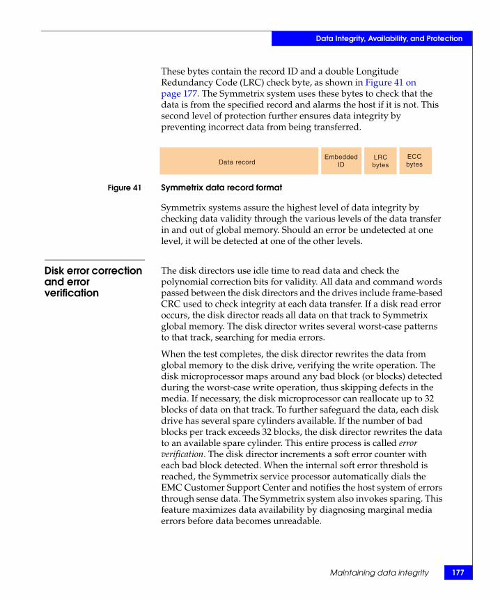
Data Integrity, Availability, and Protection
These bytes contain the record ID and a double Longitude Redundancy Code (LRC) check byte, as shown in Figure 41 on page 177. The Symmetrix system uses these bytes to check that the data is from the specified record and alarms the host if it is not. This second level of protection further ensures data integrity by preventing incorrect data from being transferred.
Figure 41 Symmetrix data record format
Symmetrix systems assure the highest level of data integrity by checking data validity through the various levels of the data transfer in and out of global memory. Should an error be undetected at one level, it will be detected at one of the other levels.
Disk error correction and error verification
The disk directors use idle time to read data and check the polynomial correction bits for validity. All data and command words passed between the disk directors and the drives include frame-based CRC used to check integrity at each data transfer. If a disk read error occurs, the disk director reads all data on that track to Symmetrix global memory. The disk director writes several worst-case patterns to that track, searching for media errors.
When the test completes, the disk director rewrites the data from global memory to the disk drive, verifying the write operation. The disk microprocessor maps around any bad block (or blocks) detected during the worst-case write operation, thus skipping defects in the media. If necessary, the disk microprocessor can reallocate up to 32 blocks of data on that track. To further safeguard the data, each disk drive has several spare cylinders available. If the number of bad blocks per track exceeds 32 blocks, the disk director rewrites the data to an available spare cylinder. This entire process is called error verification. The disk director increments a soft error counter with each bad block detected. When the internal soft error threshold is reached, the Symmetrix service processor automatically dials the EMC Customer Support Center and notifies the host system of errors through sense data. The Symmetrix system also invokes sparing. This feature maximizes data availability by diagnosing marginal media errors before data becomes unreadable.
Data recordECCbytes
LRCbytes
EmbeddedID
Maintaining data integrity 177
178
Data Integrity, Availability, and Protection
Note: “Sparing in Symmetrix systems” on page 211 provides information on sparing functionality.
Global memory director data integrity logic
The global memory director technology implements the following data integrity logic on the Symmetrix DMX global memory directors:
◆ “Global memory error correction and error verification” on page 178
◆ “Global memory chip-level redundancy” on page 179◆ “Longitude redundancy code (LRC)” on page 179◆ “Byte-level parity checking” on page 179◆ “Global memory access path protection” on page 180
Global memory error correction and error verification
In addition to monitoring recoverable conditions during normal access, all locations in global memory are periodically read and rewritten to detect any increase in single-bit errors. This memory verification technique maintains a record of errors for each memory segment. If the predetermined (single-bit) error threshold is reached in a certain segment, the service processor generates a Call Home for immediate attention.
Constant memory verification to detect and correct single-bit and nonconsecutive double-bit errors dramatically reduces the potential for multibit or hard errors. Should a multibit error be detected during the scrubbing process, it is considered a permanent error. This error is corrected and the segment is immediately fenced (removed from service) and the segment's contents are moved to another area alienable memory.
A service processor Call Home alerts EMC Global Service Call Centers whenever an unacceptable level of errors has been detected and a nondisruptive global memory director replacement is ordered. Customer Service is immediately notified of all call-home alerts, and a Customer Service Engineer can be dispatched with the appropriate parts for speedy repair. Even in cases where errors are occurring and are easily corrected, if they exceed a preset level, the call home is executed. This represents the EMC philosophy of not accepting any errors.
Error verification maximizes data availability by significantly reducing the probability of encountering an uncorrectable error by preventing bit errors from accumulating in global memory.
EMC Symmetrix DMX-4 Product Guide
79
Data Integrity, Availability, and Protection
Maintaining data integrity 1
In the mainframe host environment, the Symmetrix system reports uncorrectable bit errors as Equipment Checks to the CPU. These errors appear in the IBM EREP file.
Global memory chip-level redundancy
Traditional cache systems usually provide for eight bits of parity information to support bit error correction and detection in a 64-bit long word. The global memory directors incorporate single-nibble correction double-nibble detection capabilities. (A nibble is four consecutive bits of information.) Global memory chip-level redundancy is achieved by internally generating 16 bits of ECC parity information and replacing the incoming parity information. This enables the system to correct up to four bit errors associated with a 64-bit-long word and can detect up to eight bit errors. It also interleaves 64 bits of information plus 16 global memory director parity information (total 80 bits) across 20 memory chips on the global memory director. This results in each memory chip storing only a nibble of information corresponding to a word. So, a chip-level error will disable access only to the nibble stored on that faulty chip. However, the global memory director enables regeneration of data from the faulty chip. This leads to chip-level redundancy, making every chip on the global memory director redundant.
Redundant global memory
Symmetrix DMX-4 global memory director operations are redundant by way of a primary and secondary global memory director working as a pair. If an error is detected in one of the memory directors, no writes are allowed to the board containing the error. The writes will be made to the nonfailing memory director until the failed global memory director is replaced.
Longitude redundancy code (LRC)
Symmetrix global memory directors also incorporate sector-level Longitudinal Redundancy Checks (LRCs), which further assure data integrity. The check bytes are the XOR (exclusive OR) value of the accumulated bytes in a 4 KB sector. LRC checking can detect both data errors and incorrect block access problems.
Byte-level parity checking
All data paths and control paths have parity generating and checking circuitry that verify data integrity at the byte or word level. All data and command I/Os passed through the direct matrix interconnect, and within each channel/disk director and global memory director, include parity bits used to check integrity at each stage of the data transfer. This provides a system-wide error checking capability.

180
Data Integrity, Availability, and Protection
Global memory access path protection
Before Symmetrix global memory can accept data from a host connection, it must ensure that the area to which the data is to be written is without error. The Symmetrix system assures the highest level of data integrity by checking data validity through the various levels of the data transfer in and out of global memory.
EMC Symmetrix DMX-4 Product Guide
Data Integrity, Availability, and Protection
DMX-4 security featuresThis section describes the security features offered with the Symmetrix DMX-4 systems.
Enginuity 5773 supports the following security feature:
◆ “IPsec security features” on page 187 — The GigE IPv4/v6 (IPsec capable) channel director provides support for the latest Internet Protocol standards, including IPsec (Internet Protocol Security) and IPv6.
Enginuity 5772 or higher supports the following security features:
◆ “Symmetrix Service Credential, Secured by RSA” on page 182 — The Symmetrix Service Credential, Secured by RSA, prevents unauthorized service actions by authenticating valid identities on the service processor. This is enabled through strong authentication with industry-leading RSA technology, including a user password and encrypted credential that varies by user, action, system, and time.
◆ “Symmetrix Audit Log” on page 185 — The Audit Log records major activities on the Symmetrix, including host-initiated actions, physical component changes, actions on the service processor, and attempts blocked by security controls such as Symmetrix Access Control. The Audit Log is secure and tamper-proof: event contents cannot be altered and access can be restricted, for example, using the Auditor role within Solutions Enabler v6.4.
◆ “RSA enVision log security” on page 185 — The Symmetrix Audit Log can now be integrated with RSA enVisionTM. RSA enVision is a security information management platform that consolidates and analyzes security logs from multiple sources across the enterprise, including firewalls, access controls, servers, and applications. RSA enVision correlates events to identify hacker attacks or other security threats and generates reports for compliance with regulatory requirements such as the Sarbanes Oxley Act of 2002.
◆ “EMC Certified Data Erasure for Symmetrix Disks” on page 186 — EMC Certified Data Erasure for Symmetrix disks is a service processor-based offering for failed disks within DMX-4 systems. The erasure function overwrites data multiple times in adherence with the Department of Defense specification 5220.22-M.
DMX-4 security features 181

182
Data Integrity, Availability, and Protection
EMC Symmetrix DMX-4 Product Guide
It complements EMC data erasure service for Symmetrix and CLARiiON® frames, as well as a new EMC data erasure service for Fibre Channel and ATA disks removed from Symmetrix, CLARiiON, and Celerra® systems. Customers also can use ResourcePak®, working with EMC Certified Data Erasure service, to erase volumes on mainframe-attached Symmetrix systems.
◆ Symmetrix Access Control restricts management actions to approved hosts, and user authorization, which provides role-based access control for Symmetrix administration.
Security overview The security features and enhancements provide industry leading security to enterprise storage by:
◆ Assessing risk — By providing professional security services from EMC and selected partners including Security Classification Service and Security Assessment Service.
◆ Securing people — By providing integrated IAM solutions from EMC and selected partners including LUN masking Symmetrix access control and secure service credentials.
◆ Securing infrastructure — By providing information infrastructure from EMC including Secure Remote Support Gateway.
◆ Securing data — By providing data protection solutions from EMC and selected partners, including Encryption Design and Implementation Service, Data Erasure Service for Symmetrix, and disk erasure.
◆ Assuring policy compliance — Integrated SIEM solutions from EMC and selected partners including Symmetrix Audit Log and auditing enhancement.
Symmetrix Service Credential, Secured by RSA
The Service Credential technology applies exclusively to service processor activities and not host-initiated actions on Symmetrix devices. These service credentials describe who is logging in, what capabilities they have, a time frame that this credential is good for, and auditing of what actions the service personnel performed. If these credentials are not validated by Symmetrix, the user will not be able to log into the service processor and other internal CE functions. SSC covers both on site and remote login to Symmetrix.

Data Integrity, Availability, and Protection
Some of the security features are transparent to the customer such as service access authentication and authorization by the EMC CE and Service Credential (SC) (user ID information) restricted access (service processor and CE internal functions). Access is definable at a user level, not just at a host level. All Symmetrix user ID information information will be encrypted for secure storage within the Symmetrix. Service processor-based functions will honor Solutions Enabler Access Control settings per authenticated user in order to limit view/control of non-owned devices in shared environments such as Symmetrix or SRDF-connected systems.
Note: The following section contains additional information on access control and authorization.
Access control and user authorization
Shared systems, like a Symmetrix storage array, may be vulnerable to one host, accidentally or intentionally, tampering with another’s devices. Many product applications such as EMC ControlCenter, TimeFinder, SRDF, Optimizer, and various ISV products can issue management commands to any visible device in a Symmetrix system. Windows hosts can manipulate UNIX data.
To prevent this, Symmetrix Access Controls can be established by an administrator of the Symmetrix storage site to set up and restrict host access to and actions on defined sets of devices (access pools) across the various Symmetrix systems.
When access controls are enabled, the Symmetrix system receives and validates the host system request based on permissions as defined in the Access Control Database. Depending upon on the database content, the host system management syscall may either be processed normally or denied. If it is denied, an appropriate entry will be placed in the local host systems SYMAPI log as well as the Symmetrix Audit Log.
The Solutions Enabler SYMCLI command (symacl), as well as a new Access Control interface within the Symmetrix Management Console (SMC) version 5.3 and later, support Symmetrix Access Control database management. The CLI and SMC interfaces allow users to simply and easily set up and maintain an access controlled environment.
DMX-4 security features 183

184
Data Integrity, Availability, and Protection
For additional granularity, user-based authorization provides a tool for restricting the management operations to individual users. User-based authorization and Access Control’s host-based authorization are independent utilities that can be used either individually or, for enhanced security, in tandem. User authorization is managed using SMC or the SYMCLI symauth command.
With user Authorization, a username can be mapped to a specific role, which defines the operations that they are permitted to perform on the Symmetrix array. User Authorization is configured independently for each Symmetrix array. A Role is a pre-defined set of permissions, or access types, that determine what operations a user can perform. Unlike host-based access control, a user is assigned a particular Role for the entire Symmetrix array rather than for individual logical devices or classes of devices. Roles are predefined in Solutions Enabler and cannot be modified.
For each Symmetrix array, a given user can only be assigned a single role as follows:
◆ None — No actions authorized.
◆ Monitor — Able to perform read-only (passive) operations on a Symmetrix array, excluding the ability to read the audit log or Access Control definitions.
◆ Storage Admin — Able to perform all management operations on a Symmetrix array and modify GNS group definitions in addition to all Monitor operations.
◆ Admin — Able to perform all operations on a Symmetrix array, including security and Monitor operations.
◆ Security Admin — Able to perform security operations (symaudit, symacl, symauth) on a Symmetrix array in addition to all Monitor operations.
◆ Auditor — Grants the ability to view, but not modify, security settings for a Symmetrix array (including reading the Symmetrix Audit Log, symacl list and symauth) in addition to all Monitor operations. This is the minimum role required to view the Symmetrix Audit Log.
EMC Symmetrix DMX-4 Product Guide

Data Integrity, Availability, and Protection
Symmetrix Audit Log The Symmetrix Audit Log logs EMC maintenance activities taking place on the Symmetrix service processor, as well as with host-initiated actions and physical component changes. Host commands may then be used to retrieve information from the Symmetrix Audit Log file, using the new Auditor role (just one way to restrict Audit Log access) specified within Solutions Enabler that accompanies Enginuity 5772 or higher. Another critical security feature is that logged entry contents cannot be altered.
The audit log resides on the Symmetrix file system (SFS) within the array. Once the 40 MB capacity limit is reached, rotating log files begin to overwrite themselves. There is no need for organizations to maintain this file, unless they want to capture records before the circular 40 MB space recycles. It is important to note that organizations will need to regularly monitor and capture Audit Log contents should they need to retain history beyond the 40 MB capacity.
Note: Access to the Audit Log can be restricted in an open systems environment by utilizing Symmetrix Access Control or the new user authentication features of Solutions Enabler. Utilizing these methods, hosts or users that have been explicitly granted access will have the ability to view audit log entries.
RSA enVision log security
RSA enVision supports log collection from Symmetrix. The RSA enVision compliance and security information management platform consolidates and analyzes enterprise-wide security logs from sources such as firewalls, access controls, servers, applications, and storage devices. The platform then correlates events to identify hacker attacks or other security threats, and generates reports for compliance with regulatory requirements such as Sarbanes Oxley.
The Solutions Enabler event daemon can be configured to automatically push Symmetrix Audit Log entries to RSA enVision at scheduled intervals. This integration saves time and resources by simplifying log management. It also helps the user track Symmetrix events in the context of the larger environment while improving compliance reporting on Symmetrix activities.
DMX-4 security features 185

186
Data Integrity, Availability, and Protection
RSA enVision also provides configurable security alerts with thresholds based on the frequency of various security-related events, such as the following:
◆ Denied login attempts on a host
◆ Denied login attempts on the service processor
◆ Attempts to escalate privileges on Solutions Enabler
◆ Attempts to escalate privileges on the service processor
◆ Symmetrix Access Control violations
◆ Removal of physical drives
◆ Successful disk erasure events
◆ Unsuccessful disk erasure events
◆ Start of a remote file transfer between the customer environment and EMC Service personnel
This integration is available with RSA enVision v3.5 and either DMX-3 or DMX-4 systems running Enginuity 5772 or higher.
EMC Certified Data Erasure for Symmetrix Disks
Data Erasure erases data on a physical medium where the granularity is an entire physical drive. The erasure can vary between a single pass write of data to the drive, all the way to multi pass erasure using complex algorithms as used in DoD 5220.22-M. The intent of secure disk erase is to remove all recoverable user data from a given physical drive, or report that the attempt to remove the data was unsuccessful.
Running Data Erasure Upon purchase of the EMC Certified Data Erasure for Symmetrix Disks licence, a configuration change will be executed by the CE at time of installation, or at a later time, to enable this feature. The EMC Certified Data Erasure for Symmetrix Disks licence will enable the following functions to be performed. Data Erasure will commence on the “Not Ready” spare automatically, as long as sufficient numbers of permanent spares exist.
Provided the secure disk erase completes successfully, this process will allow a single CE visit to replace a failed drive with a new drive and return the failed drive to EMC. The customer may then reference the audit log for evidence and proof of successful Data Erasure.
EMC Symmetrix DMX-4 Product Guide
Data Integrity, Availability, and Protection
Note: The EMC Certified Data Erasure for Symmetrix Disks software requires that the customers purchase a supporting service that includes the ability to retain drives that cannot be erased.
If the customer has purchased the EMC Certified Data Erasure for Symmetrix Disks Service, the following services will be provided by the EMC CE:
◆ A certificate of completion for all disks successfully erased.
◆ Those nonerasable drives will be left with the customer for disposition at no additional charge.
EMC Certified Data Erasure will have the ability to restart (continuing where it left off on the physical disk) without script intervention after DA failover, IML, or power down. Enginuity will log an event indicating that disk erasure has completed. This status should be of high enough severity to cause the Symmetrix to call home. Enginuity will also provide data detailing the results of the completed Disk Erasure process so that a log file of the process can be created.
Data Erasureguidelines
The following guidelines must be adhered to during the Data Erasure process:
◆ Data Erasure requires permanent sparing. Disk Erasure is invoked only upon successful completion of permanent sparing.
◆ Data Erasure will only be able to run on an uninvoked “Not Ready” spare. This prevents a drive that is visible to the host from being exposed to Data Erasure.
Note: “Permanent sparing” on page 212 contains additional information.
IPsec security features
The GigE IPv4/v6 (IPsec capable) channel directors provide support for the latest Internet Protocol standards, including IPv6 and IP Security (IPsec). These new directors contain an embedded line-grade encryption co-processor to enable strong encryption for SDRF-over-IP connections without degrading performance. IPsec is enabled through a separately purchased software license. IPsec capabilities will be configured using SMC or by EMC using the Service Processor. The new IPsec capable channel directors can support any combination of IPv4/v6 and IPsec or no IPsec on either DMX-3 or DMX-4 systems.
DMX-4 security features 187

188
Data Integrity, Availability, and Protection
Status and configuration can also be monitored and viewed with SYMCLI commands. The number of IPsec sessions will be limited to 100 per port depending on the policy configuration. IPsec can be enabled for SRDF connections. IPsec enabled and IPsec disabled channel directors can co-exist in the same Symmetrix.
The benefits of this director are as follows:
◆ Reduce the security risks associated with transmitting data over IP networks.
◆ Symmetrix-native encryption hardware eliminates the need for encryption appliances, reducing cost and complexity.
◆ Allows customers to effectively manage Symmetrix communication and encryption with one interface—Symmetrix Management Console (SMC).
What is IPsec IPsec (Internet Protocol Security) is a framework for security of network communication. IPsec allows two computers to trust each other's identity and share a private key for each communications session. Based on this session key, the computers establish an encrypted communications channel and can verify that data they receive is what was originally sent.
These countermeasures mitigate many security attacks, including spoofing, tampering with data en route, connection hijacking, eavesdropping, and replay of transmission. IPsec is the same security technology used in many corporate VPN solutions, including EMC’s, to secure communication between a remote PC and corporate systems.
EMC Symmetrix DMX-4 Product Guide
89
Data Integrity, Availability, and Protection
Data protection guidelines 1
Data protection guidelinesThe Symmetrix data protection options ensure a higher level of data protection, recoverability, and availability than the standard Symmetrix availability and reliability features. The options listed in Table 28 on page 190 can be purchased separately and implemented into the Symmetrix operation.
CAUTION!To ensure continuous data availability, EMC strongly recommends that you use one or more of the data protection schemes for your Symmetrix volumes as described in Table 28 on page 190.
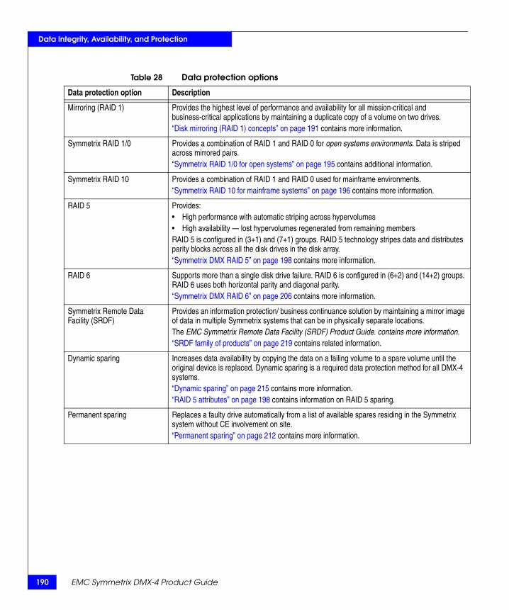
190
Data Integrity, Availability, and Protection
Table 28 Data protection options
Data protection option Description
Mirroring (RAID 1) Provides the highest level of performance and availability for all mission-critical and business-critical applications by maintaining a duplicate copy of a volume on two drives. “Disk mirroring (RAID 1) concepts” on page 191 contains more information.
Symmetrix RAID 1/0 Provides a combination of RAID 1 and RAID 0 for open systems environments. Data is striped across mirrored pairs. “Symmetrix RAID 1/0 for open systems” on page 195 contains additional information.
Symmetrix RAID 10 Provides a combination of RAID 1 and RAID 0 used for mainframe environments.“Symmetrix RAID 10 for mainframe systems” on page 196 contains more information.
RAID 5 Provides: • High performance with automatic striping across hypervolumes• High availability — lost hypervolumes regenerated from remaining members RAID 5 is configured in (3+1) and (7+1) groups. RAID 5 technology stripes data and distributes parity blocks across all the disk drives in the disk array. “Symmetrix DMX RAID 5” on page 198 contains more information.
RAID 6 Supports more than a single disk drive failure. RAID 6 is configured in (6+2) and (14+2) groups. RAID 6 uses both horizontal parity and diagonal parity. “Symmetrix DMX RAID 6” on page 206 contains more information.
Symmetrix Remote Data Facility (SRDF)
Provides an information protection/ business continuance solution by maintaining a mirror image of data in multiple Symmetrix systems that can be in physically separate locations.The EMC Symmetrix Remote Data Facility (SRDF) Product Guide. contains more information.“SRDF family of products” on page 219 contains related information.
Dynamic sparing Increases data availability by copying the data on a failing volume to a spare volume until the original device is replaced. Dynamic sparing is a required data protection method for all DMX-4 systems.“Dynamic sparing” on page 215 contains more information.“RAID 5 attributes” on page 198 contains information on RAID 5 sparing.
Permanent sparing Replaces a faulty drive automatically from a list of available spares residing in the Symmetrix system without CE involvement on site.“Permanent sparing” on page 212 contains more information.
EMC Symmetrix DMX-4 Product Guide
Data Integrity, Availability, and Protection
Disk mirroring (RAID 1) conceptsSymmetrix Mirroring (RAID 1) provides the highest level of performance and availability for all mission-critical and business-critical applications. Mirroring maintains a duplicate copy of a logical volume on two physical drives. The Symmetrix system maintains these copies internally by writing all modified data to both devices. The mirroring operation is transparent to the host.
The mirroring feature designates from two to four logical volumes residing on different physical devices as a mirrored volume, one volume being mirror-1 and the other volumes being mirror-2, mirror-3c, and mirror-4. The host views the mirrored volumes as the same logical volume because each has the same unit address.
Advantages of mirroring
Symmetrix Mirroring offers the following advantages:
◆ Improved performance over traditional mirrored (RAID 1) data protection by supporting 100-percent fast write and two simultaneous internal data transfer paths.
◆ Protection of mission-critical data from any single point of failure.
◆ Assurance that the second copy of data is identical to the first copy.
◆ Superior read performance since both mirrors are used for read operations.
◆ Continuous business operation in a situation where there is a device failure.
◆ Automatic resynchronization of the mirrored pair after repairing the defective volume.
Write operations with mirroring
Symmetrix systems handle a write operation to a mirrored logical volume as a normal write operation. The channel director presents channel end and device end (or a good-ending status) to the channel after data is written to, and verified in, global memory. The disk directors then destage the data to each drive of the mirrored pair asynchronously. As such, mirroring on Symmetrix systems exploits the 100-percent fast write capability, and the application does not see additional time associated with having to physically perform two disk write I/Os (one to each drive of the mirrored pair) as normally occurs with mirroring.
Disk mirroring (RAID 1) concepts 191
192
Data Integrity, Availability, and Protection
EMC Symmetrix DMX-4 Product Guide
Read operations with mirroring
During read operations, if the data is not available in global memory, the Symmetrix system reads the data from the volume chosen for best system performance. Performance algorithms within the Enginuity operating environment track path busy information, as well as actuator location, and which sector is currently under the disk head in each device.
Symmetrix performance algorithms for read operations choose the best volume in the mirrored pair based upon three service policies used to balance system performance:
◆ Interleave Service Policy — Shares the read operations of the mirrored pair by reading tracks from both drives in an alternating method, a number of tracks from M1, and a number of tracks from M2. Interleave is designed to achieve maximum throughput.
◆ Split Service Policy — Differs from Interleave because read operations are assigned to either the M1 or the M2 logical volume, but not both. Split is designed to minimize head movement.
◆ Dynamic Mirror Service Policy (DMSP) — Utilizes both Interleave and Split for maximum throughput and minimal head movement. DMSP adjusts each logical volume dynamically based on access patterns detected. This is the default mode within the Enginuity operating system.
Error recovery with mirroring
In the unlikely event that one volume in the mirrored pair fails, the Symmetrix system automatically uses the other volume without interruption of data availability. The Symmetrix system notifies the host operating system of the error and EMC Customer Support Center through the call-home feature. The EMC Product Support Engineer (PSE) then begins the diagnostic process and, if necessary, dispatches a Customer Engineer (CE) to the customer site. Once the suspect disk drive is nondisruptively replaced, the Symmetrix system reestablishes the mirrored pair and automatically resynchronizes the data with the new disk. During the data resynchronization process, the Symmetrix system gives priority to host I/O requests over the copy process to minimize the impact on performance. All new writes take place to both devices. The time it takes to resynchronize the mirrored pair depends on the I/O activity to the volume, the disk drive, and the disk capacity.
93
Data Integrity, Availability, and Protection
Disk mirroring (RAID 1) concepts 1
Dynamic Mirror Service Policy (DMSP)
The Symmetrix DMSP is a feature of the adaptive algorithms in the Symmetrix architecture that improves the performance of read operations in mirrored and Business Continuance Volume (BCV) environments. The improved system performance is a result of the Symmetrix system balancing the load between physical disk drives and disk directors, and minimizing actuator movement.
To achieve this improved performance, the Symmetrix system measures and tracks I/O activities of logical volumes (including business continuous volumes), physical volumes, and disk directors (FEBE board back-end function). Then, based on these measurements, the Symmetrix system directs read operations for mirrored data to the appropriate mirror resulting in the best overall performance of the Symmetrix system. As the access patterns and workloads change, the dynamic algorithm analyzes the new workloads and adjusts the service policies as needed.
Business Continuance Volumes (BCV)
A Business Continuance Volume (BCV) is a standard virtual device (logical volume) used for dynamic mirroring. It has additional attributes that allow it to independently support host applications and processes. It may be configured as a single mirror, a locally mirrored device, or an SRDF source (R1) device. A BCV (virtual) device can be RAID 1, RAID 5, or SRDF protected.
A business continuance sequence first involves setting, or establishing, the BCV device as an additional mirror of a standard device. Once the BCV is established as a mirror of the standard device, it is not accessible through its original device address.
The BCV device may later be separated, or split, from the standard device with which it was previously paired. After a split, the BCV device has valid data and is available for backup or other host processes through its original device address. Once host processes on the BCV device are complete, the BCV may again be mirrored to a standard device (either the same device to which it was previously attached or a different device). It can then acquire new data for other business continuance processes or update the standard device with any new data from the completed business continuance processes.

194
Data Integrity, Availability, and Protection
Virtual devices Virtual devices are space-efficient copies which do not directly consume physical storage. Each virtual device consists of pointers to data stored on a source device or in a pool of save devices. A virtual device integrates original data from a source device with updated data in the save pool to present a usable copy of a source volume. Although Virtual devices reduce physical storage requirements, they do consume Symmetrix device numbers and host addresses.
Virtual devices (VDEV) can be associated with standard or BCV devices. TimeFinder/Snap control operations can be performed on any virtual device in a device group.
Virtual devices serve as a target in virtual snap copies from either CKD or FBA source devices. Virtual devices cannot be SRDF devices.
Note: The TimeFinder/Clone Mainframe SNAP Facility Version 5.6.0 Product Guide contains additional information.
The EMC Solutions Enabler Symmetrix TimeFinder Family CLI Version 6.4 Product Guide contains additional information.
EMC Symmetrix DMX-4 Product Guide

Data Integrity, Availability, and Protection
Symmetrix RAID 1/0 for open systemsRAID 1/0 is a stripe of mirrored pairs that is used in open systems environments. Drives are first mirrored. In the process, DMSP is employed to ensure the optimal mirrored performance. Next, the data is striped across the disks. This combines the advantage of full redundancy with the additional performance offered by the striping. For open systems, this involves using metavolumes to stripe data across mirrored pairs of disks. The stripe size for this is two cylinders.
For some applications, such as Microsoft Exchange, best practices dictate that RAID 1/0 should be used over basic RAID 1 to enhance I/O capability. Microsoft Exchange’s workload is random and bursty with periods of high peaks, making this a difficult storage environment where I/O capacity per GB becomes important. Sequential reads or writes for simple concatenated volumes can only be serviced by a single M1/M2 pair until the end of the hyper is reached. Sequential read/write operations for a striped meta volume can be serviced by more spindles. For more details, please see EMC Symmetrix Storage Solutions Microsoft Exchange 2000 and 2003 Best Practices, available on the EMC Powerlink website at: http://Powerlink.EMC.com
Symmetrix RAID 1/0 for open systems 195

196
Data Integrity, Availability, and Protection
Symmetrix RAID 10 for mainframe systemsFor Symmetrix, RAID 10 is used to designate the mainframe version of RAID 1/0. For a mainframe environment, the implementation is similar, except with a stripe size of one cylinder, and is implemented in groups of eight drives.
In the past, this has also been referred to as “CKD Meta Volumes.” Four Symmetrix devices (each one fourth the size of the original mainframe device) appear as one mainframe device to the host. Any four Symmetrix logical devices can be chosen to define a RAID 10 group provided they are the same type (for example, IBM 3390) and have the same mirror configuration. Striping occurs across this group of four devices with a striping unit of one cylinder, as shown in the following figure. Each member of the stripe group is also mirrored, thereby protecting the entire set. Dynamic Mirror Service Policy (DMSP) can then be applied to the mirrored devices. The combination of DMSP with mirrored striping and concatenation to create a mainframe volume, as in Figure 42 on page 196, enables greatly improved performance in mainframe systems. RAID 10 uses four pairs of disks in its Symmetrix DMX implementation.
Figure 42 RAID 10 with Dynamic Mirror Service Policy
M1 M2
DMSPSYM-000136
EMC Symmetrix DMX-4 Product Guide

Data Integrity, Availability, and Protection
EMC has observed up to four times improvement in system performance while using a RAID 10 configuration with four pairs of disks as compared to an alternative configuration using a single pair of disks. EMC has also observed 20 percent to 30 percent improvement in back-end disk performance when DMSP is used, compared with a situation in which each of the mirrored pair serves 50 percent of the read I/Os. As users move to larger host volume sizes (3390-27s and eventually 3390-54s), the requirement for PAV/MA will accelerate. This allows for simultaneous access to different tracks (even the same track if all accesses are reads) on the same logical volume at the same time (even within the same stripe).
Symmetrix RAID 10 for mainframe systems 197

198
Data Integrity, Availability, and Protection
Symmetrix DMX RAID 5This section contains information on RAID 5 (3+1) and RAID 5 (7+1) data protection.
RAID 5 overview The Symmetrix DMX-4 supports RAID 5 data protection. RAID 5 is architected around block-based multispindle parity protection. RAID 5 implements data striping and rotating parity across all hypervolumes of a RAID 5 device. The hypervolumes must reside on different physical disks.
The following sections describe how RAID 5 functions in Symmetrix systems:
◆ “RAID 5 attributes” on page 198◆ “RAID 5 device (volume)” on page 198◆ “RAID 5 (3+1)” on page 199◆ “RAID 5 (7+1)” on page 199◆ “RAID 5 modes of operation” on page 199◆ “RAID 5 performance optimization” on page 204◆ “RAID 5 configuration rules” on page 205
RAID 5 attributes A RAID 5 device has the following attributes:
◆ RAID 5 track size is 64 KB.
◆ Data blocks are striped (or interleaved) horizontally across the members of a RAID 5 group, similar to a striped metavolume. Each member owns some data tracks and some parity tracks.
◆ RAID 5 groups can be:
• Four members per logical device, RAID 5 (3+1)• Eight members per logical device, RAID 5 (7+1)
RAID 5 device (volume)
A RAID 5 device (logical volume) is made of four or eight hypervolumes each with tracks of data and a parity that rotate. RAID 5 stripes both data and parity across all hypervolumes of the RAID 5 device. The entire set of RAID 5 hypervolumes is presented to the host as a single RAID 5 device. Figure 43 on page 199 shows a RAID 5 device consisting of four Symmetrix hypervolumes on four separate physical drives with one RAID 5 (3+1) device defined.
EMC Symmetrix DMX-4 Product Guide

Data Integrity, Availability, and Protection
Figure 43 RAID 5 data/parity (3+1)
RAID 5 (3+1) A RAID 5 (3+1) configuration consists of four Symmetrix devices with parity and data striped across each device. With this option, effectively 75 percent of the total storage capacity of a RAID 5 device is available for storing data.
RAID 5 (7+1) A RAID 5 (7+1) configuration consists of eight Symmetrix devices with data and parity striped across each device. With this option, effectively 87.5 percent of total storage capacity of each RAID 5 device is available for storing data.
RAID 5 modes of operation
RAID 5 has the following modes of operation:
◆ “Normal mode” on page 199◆ “Regeneration” on page 200◆ “Fast Copy back” on page 200
Normal mode When a RAID 5 device operates with all hypervolumes functioning, it is operating in normal mode. In normal mode, the Symmetrix DMX system accomplishes data redundancy by using the standard EXCLUSIVE OR (XOR) logic to generate and store parity that can then be used to reconstruct the information stored on a failed/failing member.
SYM-000547
LV D 1
LV B 1
LV C 1
Parity 123 Data 4 Data 7
Parity DEF Data G
Data J Data M
2
LV D 2
LV C 2
LV B
Data 1 Parity 456
Data 8 Data D
Parity GHI
Data K Data N
LV D 3
LV C 3
LV B 3
Parity 789
Parity JKL
Data 2 Data 5
Data E Data H
Data O
LV D 4
LV C 4
LV B 4
Data 3 Data 6 Data 9 Data F
Data I Data L
Parity MNO...
Physicaldisk 1
Physicaldisk 2
Physicaldisk 3
Physicaldisk 4
RAID 5logicalvolume
A
Symmetrix DMX RAID 5 199

200
Data Integrity, Availability, and Protection
Regeneration In the event that a RAID 5 hypervolume fails, the RAID 5 device operates with the surviving members. It is then running in reduced mode. The data on the failing/failed member is reconstructed by XOR’ing the information from the surviving members in the rank.
Fast Copy back After the failed disk is replaced, data is rapidly copied back from the spare drive to the newly installed drive.
Normal mode RAID 5 normal mode has the following functions:
◆ “Writing data in RAID 5 normal mode” on page 200◆ “Reading data in RAID 5 normal mode” on page 201
Writing data in RAID 5normal mode
RAID 5 requires that the controller execute two read-modify-write sequences executed concurrently Table 29 on page 200 and Figure 44 on page 201.
The Symmetrix DMX implementation of RAID 5 distributes the work of computing parity between the disk director and the disk drives using the XOR chip located on the disk drive and the disk-level buffer.
Symmetrix DMX RAID 5 optimizes performance for large sequential write workloads as there is no need to read the parity from disks. Since many sequential tracks are written, they are all in Symmetrix global memory. The parity is calculated in global memory and information is written to the disks in one stroke without requiring the use of an expensive disk-level read-XOR-write operation.
Table 29 RAID 5 write operation sequence in normal mode
Drive containing data Drive containing parity
1. Read old information2. Compute XOR bit mask3. Write new information
1. Read old information2. Receive XOR bit mask3. Write new information
EMC Symmetrix DMX-4 Product Guide

Data Integrity, Availability, and Protection
Figure 44 Writing data in RAID 5 normal mode
Reading data inRAID 5 normal mode
Read hit operations in a Symmetrix RAID 5 (Figure 45 on page 202) normal mode are processed through Symmetrix global memory as in normal Symmetrix system processing.
Write operation involves two instances of the read-modify-write sequence.
A four-track stripe of parity
A stripe of four tracks of data
XOR bit mask
Updating parity during writes
Write
Read Read
SYM-000726
Write
Symmetrix DMX RAID 5 201
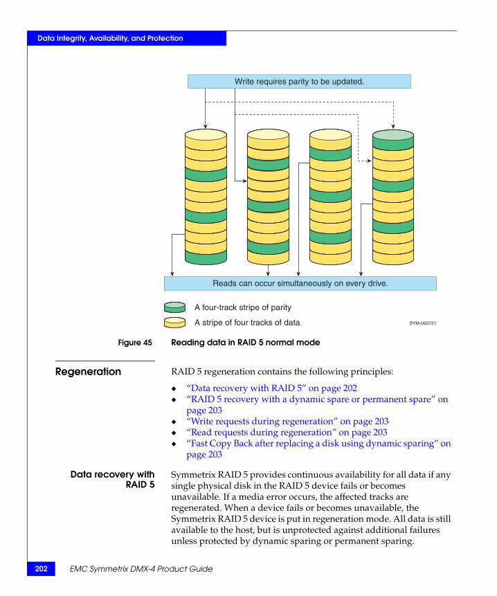
202
Data Integrity, Availability, and Protection
Figure 45 Reading data in RAID 5 normal mode
Regeneration RAID 5 regeneration contains the following principles:
◆ “Data recovery with RAID 5” on page 202◆ “RAID 5 recovery with a dynamic spare or permanent spare” on
page 203◆ “Write requests during regeneration” on page 203◆ “Read requests during regeneration” on page 203◆ “Fast Copy Back after replacing a disk using dynamic sparing” on
page 203
Data recovery withRAID 5
Symmetrix RAID 5 provides continuous availability for all data if any single physical disk in the RAID 5 device fails or becomes unavailable. If a media error occurs, the affected tracks are regenerated. When a device fails or becomes unavailable, the Symmetrix RAID 5 device is put in regeneration mode. All data is still available to the host, but is unprotected against additional failures unless protected by dynamic sparing or permanent sparing.
A four-track stripe of parity
A stripe of four tracks of data
Write requires parity to be updated.
Reads can occur simultaneously on every drive.
SYM-000727
EMC Symmetrix DMX-4 Product Guide
Data Integrity, Availability, and Protection
If a physical device reports too many errors (even recoverable errors), or fails completely, that device is taken offline by the Symmetrix system. This condition causes the Symmetrix DMX system to place a remote service call to the Customer Support Center.
The Product Support Engineer (PSE) at the support center can determine if a disk drive should be identified for replacement and dispatches a Customer Engineer (CE) who starts the Symmetrix nondisruptive interactive drive replacement process. The logical devices on the disk being replaced are placed in a not-ready state and the associated ranks will begin operating in regeneration mode. After the new drive is in place, the regeneration process begins.
RAID 5 recovery with adynamic spare orpermanent spare
If the Symmetrix DMX system has an available dynamic spare or permanent spare, it copies the data from the failing device to the spare before the device fails, and reconstructs the data if necessary from the other surviving members of the RAID 5 device. After a spare is activated, it behaves as if it is a full fledged member of the RAID 5 device.
Note: “Dynamic sparing with RAID 5 volumes” on page 217 contains information on RAID 5 regeneration with dynamic sparing and “Permanent sparing” on page 212 for RAID 5 regeneration with permanent sparing.
Write requests duringregeneration
As write requests are made during regeneration, the new data is written to the RAID 5 device consisting of the surviving members and the dynamic spare or permanent spare if one is available.
Read requests duringregeneration
Read requests for data in global memory (read hits) are serviced immediately from global memory. During regeneration, when read requests not found in global memory (read misses) occur, the required data is automatically regenerated by reading surviving members and using an XOR calculation, and is delivered to the spares pool.
Fast Copy Back afterreplacing a disk using
dynamic sparing
After the failed disk is replaced, data is rapidly copied back from the the dynamic spare to the newly installed drive. This is a fast process of simply copying track by track. After copy back is completed, the original spare drive is returned to the dynamic spare pool.
Symmetrix DMX RAID 5 203

204
Data Integrity, Availability, and Protection
Note: Symmetrix systems can be configured with dynamic sparing to restore data protection from a second drive failure. “Dynamic sparing with RAID 5 volumes” on page 217 provides more information on dynamic sparing used with Symmetrix RAID 5.
RAID 5 performance optimization
The Enginuity operating environment deploys advanced I/O optimization techniques to enhance RAID 5 performance on Symmetrix DMX systems. On sequential writes to a RAID 5 device, there is no need to read the parity from disk. Since many sequential tracks are written, they are all in Symmetrix DMX global memory and hence parity is calculated in memory and is written to disk without the expensive read-modify-write operation.
Symmetrix Optimizer deployed with RAID 5 on Symmetrix DMX systems collects statistics on I/O access on individual RAID 5 hypervolumes as well as on RAID 5 devices over extended periods of time (typically a week). Symm Optimizer provides a comprehensive analysis of the statistical data collected to identify over-and under-utilized system resources. For example, Symm Optimizer can determine if hot spots (places of high I/O activity) or cold spots (places of low I/O activity) exist. (It is typically observed that 20 percent of physical disks are doing 80 percent of the I/O activity—Pareto principle.) Symm Optimizer observes and analyzes this unbalanced workload and makes recommendations for swapping the hot spindles with the cold spindles. If policy-based automation is chosen by the customer, Symm Optimizer implements the recommendations automatically and transparently. This results in a uniformly distributed workload across all physical spindles which in turn results in enhanced performance and improved resource utilization across the entire Symmetrix DMX system.
Note: Symmetrix systems can be configured with dynamic sparing to restore data protection from a second drive failure. “Dynamic sparing with RAID 5 volumes” on page 217 provides more information on dynamic sparing used with Symmetrix RAID 5.
EMC Symmetrix DMX-4 Product Guide

Data Integrity, Availability, and Protection
RAID 5 configuration guidelines
The following are some guidelines to consider when configuring RAID 5 devices:
◆ BCVs can be RAID 5 devices.◆ SymmOptimizer Swap supports RAID 5 devices.◆ SRDF devices can be RAID 5 devices.◆ eSNAP source and destination devices can be RAID 5 devices.◆ A log device can be a RAID 5 device.◆ Concurrent Copy is supported with RAID 5.
RAID 5 configuration rules
The following configuration rules apply to RAID 5:
◆ Only one member of a RAID 5 group is permitted per drive loop. This configuration requires a minimum of eight drive enclosures for RAID 5 (7+1) and four drive enclosures for RAID 5 (3+1).
◆ RAID 5 (3+1) and (7+1) can co-exist in the same system.
◆ An n + 1 RAID 5 group requires one spare.
◆ Customers can configure more than one spare on RAID 5 systems (not in the same RAID 5 group), which can protect them from multiple drive failures.
◆ A single RAID 5 protection scheme can be configured within a system with any combination of SRDF, BCV, and mirroring protection.
◆ When a spare is invoked against a RAID 5 member, the same track can be valid on either the member or the spare, not both at the same time.
Symmetrix DMX RAID 5 205

206
Data Integrity, Availability, and Protection
Symmetrix DMX RAID 6This section contains information on RAID 6 (6+2) and RAID 6 (14+2) data protection.
RAID 6 overview RAID 6 is defined as any configuration that supports more than a single disk drive failure. Similar to RAID 5 devices, the data blocks are striped/interleaved across all members of the RAID group.
The following sections describe how RAID 6 functions in Symmetrix systems:
◆ “RAID 6 attributes” on page 206
◆ “RAID 6 device (volume)” on page 206
◆ “Even-Odd algorithm” on page 207
◆ “RAID 6 (6+2)” on page 208
◆ “RAID 6 (14+2)” on page 208
◆ “Rebuilding data and parity members” on page 209
◆ “RAID 6 configuration guidelines” on page 210
◆ “Comparing RAID 5 and RAID 6” on page 210
RAID 6 attributes A RAID 6 device has the following attributes:
◆ RAID 6 track size is 64K.
◆ Data blocks are striped/interleaved across all members of the RAID group.
◆ RAID 6 groups can be:
• Eight members per logical device (6+2).
• Sixteen members per logical device (14+2).
RAID 6 device (volume)
A RAID 6 device (logical volume) is made of eight or sixteen hypervolumes each with tracks of data and a parity that rotate. RAID 6 stripes both data and parity across all hypervolumes of the RAID 6 device. Logically, the RAID 6 device is represented as a single mirror device.
EMC Symmetrix DMX-4 Product Guide
07
Data Integrity, Availability, and Protection
Symmetrix DMX RAID 6 2
Figure 46 on page 208 shows a RAID 6 device consisting of Symmetrix hypervolumes on eight separate physical drives. Six data drives (D1–D6) and two parity drives (D7 horizontal parity and D8 diagonal parity).
Figure 47 on page 209 shows a RAID 6 device consisting of Symmetrix hypervolumes on 16 separate physical drives. Fourteen data drives (D1–D14) and two parity drives (D15 horizontal parity and D16 diagonal parity).
Even-Odd algorithm The algorithm used by Symmetrix for RAID 6 is an XOR based algorithm called Even-Odd.
This algorithm calculates two types of parity — Horizontal Parity (HP) and Diagonal Parity (DP), in order to provide protection against the loss of two members of the RAID group. The two parities are calculated using different sets of the user data, and are independent of one another. Horizontal Parity is the equivalent of RAID 5 parity, and is calculated from the data across all the data disks. Diagonal Parity (DP) is made up of segments; each DP segment is calculated on a selected group of data segments. Each DP segment skips a different data drive in its calculation, which is key to the ability of this algorithms to reconstruct data after a double drive failure.
Another important requirement of this algorithm is that the number of data drives used in the DP calculations be a prime number. Symmetrix offers RAID 6 (6+2) and RAID 6 (14+2) protection (6 data or 14 data, with 2 parities each), neither of which is 'prime'. The Symmetrix implementation of Even-Odd assumes there to be 17 data drives in the RAID group—named D1–D17. For each of the protection schemes, the 'real' data drives take up positions D1–D6 (for 6+2) or D1–D14 (for 14+2) in the DP calculations; the remaining drives (Dx up to D17) are 'NULL disks'. These NULL disks exist only for the sake of the DP calculations, and the 'data' on these NULL disks is assumed to be all zero when calculating parity. These NULL disks do not consume any system resources (memory, cache, or disks). Figure 46 on page 208 and Figure 47 on page 209 show the RAID 6 data/parity layouts for RAID 6 (6+2) and RAID 6 (14 +2), respectively.

208
Data Integrity, Availability, and Protection
RAID 6 (6+2) A RAID 6 (6+2) configuration consists of eight Symmetrix devices with parity and data striped across each device. With this option, effectively 75 percent of the total storage capacity of a RAID 6 device is available for storing data.
Figure 46 on page 208 shows a RAID 6 (6+2) data/parity layout.
Figure 46 RAID 6 (6+2) data/parity layout
RAID 6 (14+2) A RAID 6 (14+2) configuration consists of sixteen Symmetrix devices with parity and data striped across each device. With this option, effectively 87.5 percent of the total storage capacity of a RAID 6 device is available for storing data.
0
SYM-001302
7
D1 D2 D3 D4 D5 D6 N N N N N N N N N N N 0
1 2 3
4 5 6
7 8
9 10 11 12 13 14 15
0 1 2
3 4 5
6 7
8 9 10 11 12 13 14
15 16
16 14 15
13 14 15
12 13 14
15
11 12 13
14 15
10 11 12
13 14 15
9 10 11
12 13 14
15
8 9 10
11 12 13
14 15
7 8 9
10 11 12
13 14
15
6 7 8
9 10 11
12 13
14 15
5 6 7
8 9 10
11 12
13 14 15
4 5 6
7 8 9
10 11
12 13 14 15
3 4 5
6 7 8
9 10
11 12 13 14 15
2 3 4
5 6 7
8 9
10 11 12 13 14 15
1 2 3 4 5 6 7 8 9 10 11 12 13 14 15 16 D8 P0
P1 P2 P3
P4 P5 P6
P7 P8
P9 P10 P11 P12 P13 P14 P15
D7 H0
H1 H2 H3
H4 H5 H6
H7 H8
H9 H10 H11 H12 H13 H14 H15 16
16 16
16
16 16
16 16
16
16 16
16
16
0 1 2 3 4 5 6
0
1 2 3 4 5 6
0 1
2 3 4 5 6 7 8
0
1 2
3 4 5 6 7 8 9
0 1
2 3
4 5 6 7 8 9
0 1 2
3 4
5 6 7 8 9 10 11
0
1 2 3
4 5
6 7 8 9 10 11
0 1
2 3 4
5 6
7 8 9 10 11 12 13 10 12
0 0
0 1 1 2
1 2 3
0 1 2 3 4
0 1 2 3 4 5
D1 Physical disk 1, in this slice there are 6 data drives, from D1 to D6
D7 Physical disk 7, in this slice it contains the Horizontal Parity
D8 Physical disk 8, in this slice it contains the Diagonal Parity
N Null disk is a nonexistent drive whose contents is always zero but existssolely for the purpose of the RAID calculations
One track of 64 K, made by 16 elements of 4 K each
cy/hd
9/9
cy/hd
9/D
cy/hd
10/2
cy/hd
10/6
cy/hd
10/A 10/E
cy/hd
Slice # 18
cy/hd
P
cy/hd
DP
Special diagonal 16
H Full track is calculated XOR all 17 horizontal tracksHorizontal parity doesn’t include the diagonal parity
P0 4 K of the Diagonal parity track
P0 is calculated by XOR all 4 K chunks marked
P1 is calculated by XOR all 4 K chunks marked
0 and XOR all chunks marked 16
1 and XOR all chunks marked 16
EMC Symmetrix DMX-4 Product Guide
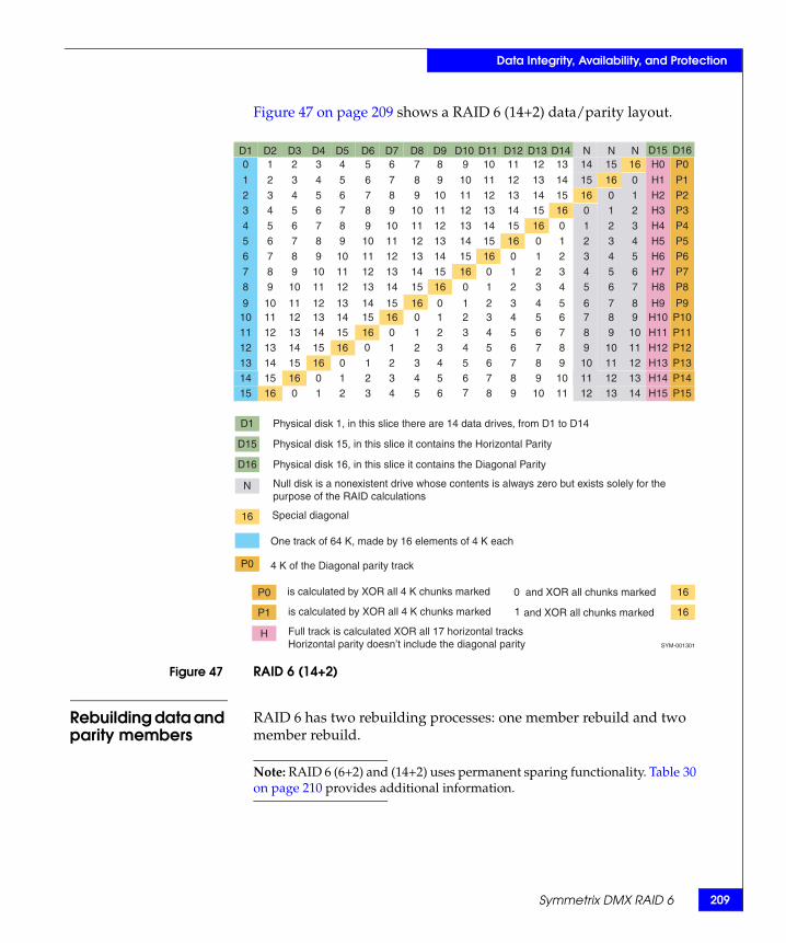
Data Integrity, Availability, and Protection
Figure 47 on page 209 shows a RAID 6 (14+2) data/parity layout.
Figure 47 RAID 6 (14+2)
Rebuilding data and parity members
RAID 6 has two rebuilding processes: one member rebuild and two member rebuild.
Note: RAID 6 (6+2) and (14+2) uses permanent sparing functionality. Table 30 on page 210 provides additional information.
0
7
SYM-001301
D1 D2 D3 D4 D5 D6 D7 D8 D9 D10 D11 D12 D13 D14 N N N 0
1 2 3
4 5 6
7 8
9 10 11 12 13 14 15
0 1 2
3 4 5
6 7
8 9
10 11 12 13 14
15 16
16 14 15
13 14 15
12 13 14
15
11 12 13
14 15
10 11 12
13 14 15
9 10 11
12 13 14
15
8 9
10
11 12 13
14 15
7 8 9
10 11 12
13 14
15
6 7 8
9 10 11
12 13
14 15
5 6 7
8 9 10
11 12
13 14 15
4 5 6
7 8 9
10 11
12 13 14 15
3 4 5
6 7 8
9 10
11 12 13 14 15
2 3 4
5 6 7
8 9
10 11 12 13 14 15
1 2 3 4 5 6 7 8 9 10 11 12 13 14 15 16 D16 P0
P1 P2 P3
P4 P5 P6
P7 P8
P9 P10 P11 P12 P13 P14 P15
D15 H0
H1 H2 H3
H4 H5 H6
H7 H8
H9 H10 H11 H12 H13 H14 H15 16
16 16
16
16 16
16 16
16
16 16
16
16
0 1 2 3 4 5 6
0
1 2 3 4 5 6
0 1
2 3 4 5 6 7 8
0
1 2
3 4 5 6 7 8 9
0 1
2 3
4 5 6 7 8 9
0 1 2
3 4
5 6 7 8 9
10 11
0
1 2 3
4 5
6 7 8 9
10 11
0 1
2 3 4
5 6
7 8 9
10 11 12 13 10 12
0 0
0 1 1 2
1 2 3
0 1 2 3 4
0 1 2 3 4 5
D1 Physical disk 1, in this slice there are 14 data drives, from D1 to D14
D15 Physical disk 15, in this slice it contains the Horizontal Parity
D16 Physical disk 16, in this slice it contains the Diagonal Parity
Null disk is a nonexistent drive whose contents is always zero but exists solely for thepurpose of the RAID calculations
Special diagonal
One track of 64 K, made by 16 elements of 4 K each
4 K of the Diagonal parity track
P0 is calculated by XOR all 4 K chunks marked
P1 is calculated by XOR all 4 K chunks marked
H Full track is calculated XOR all 17 horizontal tracks Horizontal parity doesn’t include the diagonal parity
N
16
P0
0 and XOR all chunks marked 16
1 and XOR all chunks marked 16
Symmetrix DMX RAID 6 209

210
Data Integrity, Availability, and Protection
EMC Symmetrix DMX-4 Product Guide
One member rebuild In a one member rebuild, the data members rebuild like RAID 5, the horizontal parity rebuilds like RAID 5, and diagonal parity rebuilds using data from all data members.
Two member rebuild In a two data member rebuild, the rebuild is segment by segment recursively using both horizontal and diagonal parities. In a one data member and horizontal parity rebuild, the data member is rebuilt using diagonal parity. The horizontal parity is rebuilt using all data members.
In a one data member and diagonal parity rebuild, the data member is rebuilt using horizontal parity. The diagonal parity is rebuilt using all data members. In a horizontal parity and diagonal parity rebuild, both horizontal and diagonal parity are rebuilt using all data member data.
RAID 6 configuration guidelines
The following are some guidelines to consider when configuring RAID 6 devices:
◆ BCVs can be RAID 6 devices.◆ SymmOptimizer Swap supports RAID 6 devices.◆ SRDF devices can be RAID 6 devices.◆ eSNAP source and destination devices can be RAID 6 devices.◆ A log device can be a RAID 6 device.◆ Concurrent Copy is supported with RAID 6.
Comparing RAID 5 and RAID 6
Table 30 on page 210 describes the comparisons between RAID 5 and RAID 6.
Table 30 RAID 5 and RAID 6 comparison
RAID 5 RAID 6
Uses two mirrors to represent the device: data mirror and parity mirror.
Uses a single mirror to represent the overall state of the device.
Uses mirror invalid to indicate both logical and physical invalids. Uses mirror invalid to indicate logical invalid; uses the Physical Consistency table to indicate physical inconsistent.
Supports both permanent sparing and dynamic sparing. Supports permanent sparing. If permanent sparing is not successful on the first failure, no additional action is taken. If permanent sparing is also unsuccessful after a second failure (double-degraded mode), then RAID 6 dynamic sparing will be attempted.
Uses special disk commands to perform XOR operations. Uses Symmetrix hardware functionality to perform XOR calculations.

Data Integrity, Availability, and Protection
Sparing in Symmetrix systemsSymmetrix DMX-4 systems support both permanent sparing and dynamic (temporary) sparing functionality. Sparing increases data availability with minimum impact on performance. It is used in combination with all protection types, for example, mirroring, RAID 5, RAID 6, or SRDF. Symmetrix maintains a pool of spares in various locations that can be used to support both permanent and dynamic sparing.
Sparing configuration rules and guidelines
Note: The amount of recommended spares in a Symmetrix system is calculated by the EMC ordering system.
Spare drives are required for every Symmetrix DMX-4 configuration and must follow these rules and guide lines:
2/100 per drive type with a minimum of eight spare drives per system.
These calculations are for the minimum number of spare drives. It is usually a good idea to configure more than the minimum of two spare drives per 100 drives per drive type to increase the likelihood that a permanent spare drive will be available in a good location.
Flash drive sparing rules
Flash drives are available for DMX-4 systems. Flash drives support both dynamic and permanent sparing using Flash drive spares. Symmetrix Enginuity will block sparing between Flash drives and magnetic disk drives to avoid potential performance issues.
One Flash drive spare must be configured for every 32 data drives, or portion thereof. If more than one capacity of Flash drives is installed, the Flash drive spare must be equal to the highest capacity Flash drive. This will provide dynamic sparing coverage for all Flash drives. However, permanent sparing of Flash drives requires a spare of the exact size as the failing drive.
The system spare drive requirements are not affected by the configuration of Flash drives or Flash drive spares. The system’s required amount and types of spares are solely determined by the configured magnetic disk drives. Flash drive spare requirements are determined independently.
Sparing in Symmetrix systems 211

212
Data Integrity, Availability, and Protection
Note: The EMC Customer Engineer can use Enginuity’s tools that define and enforce the many complex sparing rules. One of these tools is a disk map that shows each disk and the spares that cover it. Sparing rules are strictly enforced by Enginuity, and the minimum number of drives must be present.
Sparing benefits In summary, sparing offers the following benefits:
◆ Significantly decreases the amount of time required to rebuild and copy back the data from the failed drive.
◆ Permanent sparing has a lower total affected time than dynamic sparing.
◆ Increases protection of all volumes from loss of data.
◆ Automatically activates the spare volume without interruption prior to loss of access to a potentially failing volume.
◆ Ensures that the spare copy is identical to the original copy.
◆ Increases data availability of all volumes in use without loss of any data capacity.
◆ Is transparent to the host and requires no user intervention.
◆ Resynchronizes a new disk drive with the dynamic spare after repair of the defective device is complete.
Permanent sparing Note: When permanent sparing is enabled, dynamic sparing will only be used if there are unprotected volumes on the failing drive, or if a suitable permanent spare cannot be identified. “Dynamic sparing” on page 215 provides more information on the dynamic sparing process.
Symmetrix systems have a permanent sparing functionality that increases data availability with minimum impact on performance. Physical disks within the Symmetrix are reserved as standby spares. These spare disks are not user-addressable.
Enginuity determines when a customer disk (non-spare) is about to fail and initiates a rebuild and copy back (in parallel) of the contents of the failing disk to an available spare without any interruption in processing. The Symmetrix system notifies the EMC Customer Support Center of this event with an Environmental-Data Present error. A failing disk cannot be permanently spared by a spare disk of a different speed, block size, or capacity; even 10 K and 15 K are not compatible. Drives that contain vault volumes are candidates for permanent sparing if there is an available spare on the same DA slice.
EMC Symmetrix DMX-4 Product Guide

Data Integrity, Availability, and Protection
Permanent sparing has the added benefit of allowing an EMC Customer Engineer operating on site or from the EMC Customer Support Center to force the Symmetrix system to rebuild/copy back the contents of a customer disk to a spare. This forced copy allows the EMC Customer Engineer to test or service a disk nondisruptively while access to data continues.
Permanent sparingprocess
The permanent sparing process follows these steps: (Figure 48 on page 214):
1. Enginuity determines when a physical volume is about to fail. The Symmetrix system makes its copying decision based on error statistics maintained by its directors, the intelligent disk microprocessor self-testing information, and its active error checking system.
2. If the Symmetrix sparing algorithms determine that the number of errors occurring on a volume is excessive and that a hard failure is probable, the sparing process starts one or two of the following processes:
a. Looks for an available spare in its pool of spares, dynamically invokes it, and initiates the rebuild.
b. Looks for and identifies a spare drive of the same capacity and speed in a good location to permanently replace the failing drive.
The process identifies a good location using the following rules:
– Not on the same disk director as any other member of the RAID group.
– Not on the same loop or drive enclosure as any other member of the RAID group.
– Not on the same power branch as any other member of the RAID group.
– RAID 6 volumes can have up to two members on the same disk director or loop.
If a suitable permanent spare cannot be identified, dynamic sparing will continue.“Dynamic sparing” on page 215 provides more information on the dynamic sparing process.
Sparing in Symmetrix systems 213
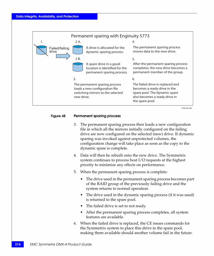
214
Data Integrity, Availability, and Protection
Figure 48 Permanent sparing process
3. The permanent sparing process then loads a new configuration file in which all the mirrors initially configured on the failing drive are now configured on the selected (new) drive. If dynamic sparing was invoked against unprotected volumes, the configuration change will take place as soon as the copy to the dynamic spare is complete.
4. Data will then be rebuilt onto the new drive. The Symmetrix system continues to process host I/O requests at the highest priority to minimize any effects on performance.
5. When the permanent sparing process is complete:
• The drive used in the permanent sparing process becomes part of the RAID group of the previously failing drive and the system returns to normal operation.
• The drive used in the dynamic sparing process (if it was used) is returned to the spare pool.
• The failed drive is set to not ready.
• After the permanent sparing process completes, all system features are available.
6. When the failed drive is replaced, the CE issues commands for the Symmetrix system to place this drive in the spare pool, making them available should another volume fail in the future.
Permanent sparing with Enginuity 57732 A.
A drive is allocated for the dynamic sparing process.
2 B.
A spare drive in a goodlocation is identified for the permanent sparing process.
1.
Failed/failingdrive
3.
The permanent sparing processloads a new configuration fileswitching mirrors to the selectednew drive.
The failed drive is replaced andbecomes a ready drive in the spare pool. The dynamic spare also becomes a ready drive in the spare pool.
6.
After the permanent sparing process completes, the new drive becomes a permanent member of the group.
5.
4.
The permanent sparing process moves data to the new drive.
SYM-001306
EMC Symmetrix DMX-4 Product Guide

Data Integrity, Availability, and Protection
Note: EMC Customer Service is usually able to replace a failed drive within four hours. The time it takes to replace and resynchronize a failed drive within a RAID 5 group depends on the I/O activity to the logical volumes, the disk drive, and the disk capacity. This time can be significantly reduced by implementing permanent sparing.
Note: “EMC Certified Data Erasure for Symmetrix Disks” on page 186 contains information on how this feature works with permanent sparing.
Dynamic sparing Dynamic sparing provides incremental protection against failure of a second disk during the time a disk is taken offline and when it is ultimately replaced and resynchronized. The dynamic sparing function determines when a logical volume is about to fail, and copies the contents of the disk drive on which that volume resides to an available spare without any interruption in processing (Figure 49 on page 215). The Symmetrix system notifies the EMC Customer Support Center of this event with an Environmental-Data Present error, and then uses the spare until the device can be replaced.
Figure 49 Dynamic sparing process
Data volume D1protected by
dynamic spare DSD1
D1(M1) D1(M2)
DSCOPY
D1(M1) D1(M2)
DS
DS
DS
COPY
D1 failing, dynamicspare invoked
DS mirrors D1
DS returns tospares pool D1
Failed diskreplaced and new
disk restored as D1
Sparing in Symmetrix systems 215
216
Data Integrity, Availability, and Protection
Note: Enginuity 5772 is no longer limited to invoking a single (same size or larger) dynamic spare to a failing drive. At 5772 dynamic spares can now be invoked at the logical device or hyper level and multiple smaller spare drives can dynamically protect a single larger failing drive. In all previous codes dynamic spares are invoked at the physical drive level and the requirement for a dynamic spare is that it has to be the same size or larger than the largest data drive.
The dynamic sparing process selects a spare drive with the same block size (512 or 520 bytes) as the failing drive. The process also chooses an available spare drive of equal or larger capacity. There is no restriction preventing a 7.2K/10K/15K spare from being invoked against any other speed failing drive. For example, it is possible that a 7.2K spare will be invoked against a 15K failing drive, which may affect performance.
Dynamic sparingprocess
With dynamic sparing, the Symmetrix system makes its copying decision based on error statistics maintained by its directors, the intelligent disk microprocessor self-testing information, and its active error checking system. If the Symmetrix dynamic sparing algorithms determine that the number of errors occurring on a volume is excessive and that a hard failure is probable, it looks for an available spare in its pool of spares.
The Symmetrix system dynamically copies all data from the device containing the failing volume to the available spare. The Symmetrix system continues to process host I/O requests at the highest priority while this copy operation takes place to minimize the effect on performance. When the copy operation completes, the Symmetrix system notifies the EMC Customer Support Center of the event. The spare and the original device work as a mirrored pair until the defective unit is replaced.
After the disk is replaced, the EMC Customer Engineer (CE) then issues commands for the Symmetrix system to dynamically copy the contents of the spare to the new device. The spare remains in use until the copy completes. When the copy has completed, the CE issues commands for the Symmetrix system to return the spare to its pool, making it available should another volume fail in the future.
EMC Symmetrix DMX-4 Product Guide
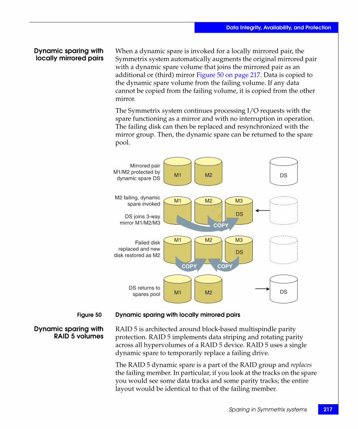
Data Integrity, Availability, and Protection
Dynamic sparing withlocally mirrored pairs
When a dynamic spare is invoked for a locally mirrored pair, the Symmetrix system automatically augments the original mirrored pair with a dynamic spare volume that joins the mirrored pair as an additional or (third) mirror Figure 50 on page 217. Data is copied to the dynamic spare volume from the failing volume. If any data cannot be copied from the failing volume, it is copied from the other mirror.
The Symmetrix system continues processing I/O requests with the spare functioning as a mirror and with no interruption in operation. The failing disk can then be replaced and resynchronized with the mirror group. Then, the dynamic spare can be returned to the spare pool.
Figure 50 Dynamic sparing with locally mirrored pairs
Dynamic sparing withRAID 5 volumes
RAID 5 is architected around block-based multispindle parity protection. RAID 5 implements data striping and rotating parity across all hypervolumes of a RAID 5 device. RAID 5 uses a single dynamic spare to temporarily replace a failing drive.
The RAID 5 dynamic spare is a part of the RAID group and replaces the failing member. In particular, if you look at the tracks on the spare you would see some data tracks and some parity tracks; the entire layout would be identical to that of the failing member.
Mirrored pairM1/M2 protected by
dynamic spare DSM1 M2
M1 M2 M3
M1 M2
M1 M2
M3
M2 failing, dynamicspare invoked
DS joins 3-waymirror M1/M2/M3
DS
DS
DS
DS
Failed diskreplaced and new
disk restored as M2
DS returns tospares pool
COPY
COPY COPY
Sparing in Symmetrix systems 217
218
Data Integrity, Availability, and Protection
Enginuity supports a direct copy mode between the spare and the failing member. For example, once the failing drive is replaced, Enginuity will avoid rebuilding the data to the new drive. Instead, it will copy the tracks (both data and parity) directly from the spare to the new drive. This is a much faster way of validating the new drive. The Symmetrix system has a sense of copy direction. When a spare is invoked, the default copy direction is from the failing member to the spare. The spare has a mirror number of its own that never changes.
Note: Dynamic sparing cannot be used with RAID 6 volumes.
Dynamic sparing withremotely mirrored
pairs (SRDF)
When the dynamic sparing option is invoked for a remotely mirrored SRDF pair, the Symmetrix system automatically activates an available spare in the Symmetrix unit containing the failing device and copies data from the failing device to the spare. The Symmetrix system continues processing I/Os (with the spare functioning as one of a mirrored pair with the failing device), and its remote mirror continues with no interruption in operation. If the Symmetrix system cannot copy all data from the failing device to the spare, it retrieve the unavailable data from the good member of the remote pair.
EMC Symmetrix DMX-4 Product Guide

Data Integrity, Availability, and Protection
SRDF family of productsThe EMC Symmetrix Remote Data Facility (SRDF) family of replication software offers various levels of Symmetrix based business continuance and disaster recovery solutions. The SRDF products offer the capability to maintain multiple, host-independent, mirrored copies of data. The Symmetrix systems can be in the same room, in different buildings within the same campus, or hundreds to thousands of kilometers apart.
By maintaining copies of data in different physical locations, SRDF enables you to perform the following operations with minimal impact on normal business processing:
◆ Disaster restart◆ Disaster restart testing◆ Recovery from planned outages◆ Remote backup◆ Data center migration◆ Data replication and mobility
Note: The EMC Symmetrix Remote Data Facility (SRDF) Product Guide contains specific information on the SRDF family of products.
Base SRDF family products
The SRDF family consists of three base solutions:
◆ SRDF/Synchronous (SRDF/S) — High-performance, host-independent, real-time synchronous remote replication from one Symmetrix to one or more Symmetrix systems.
◆ SRDF/Asynchronous (SRDF/A) — High-performance extended distance asynchronous replication using a Delta Set architecture for optimal bandwidth utilization and minimal host performance impact.
◆ SRDF/Data Mobility (SRDF/DM) — Rapid transfer of data from source volumes to remote volumes anywhere in the world, permitting information to be shared and content to be distributed, or information consolidated for parallel processing activities.
SRDF family of products 219

220
Data Integrity, Availability, and Protection
SRDF family options There are a number of additional options and features that can be added to the base solutions to solve specific service level requirements. These options include:
◆ SRDF/Automated Replication (SRDF/AR) solutions for meeting very specific, remote replication service-level requirements.
◆ SRDF/Star for advanced multisite failover with continuous protection.
◆ SRDF/Consistency Groups (SRDF/CG) for data consistency.
◆ SRDF/Cluster Enabler (SRDF/CE) for integration with host-based clustering products such as Microsoft Cluster Server (MSCS).
SRDF/A resiliency features
There are a number of additional SRDF/A features that can be added to the base solution to solve specific service level requirements. These features include:
◆ SRDF/A Reserve Capacity enhances SRDF/A's ability to maintain operational state when encountering network resource shortfalls that would have previously suspended SRDF/A operations. With SRDF/A Reserve Capacity functions enabled, additional resource allocation can be applied to address temporary workload peaks, periods of network congestion, or even temporary network outages.
The two functions that implement SRDF/A Reserve Capacity are Transmit Idle and Delta Set Extension (DSE), and they work together to maximize availability of continuous remote replication operations while minimizing operational overhead:
• SRDF/A Transmit Idle enables asynchronous replication operations to remain active in the event all links are lost temporarily due to network outages. The time SRDF/A remains active will depend on the system not reaching the system write pending limit or SRDF/A max cache limit, which is user setable.
• SRDF/A Delta Set Extension or DSE enables asynchronous replication operations to remain active in the event system cache resources are becoming in danger of reaching the system write pending or SRDF/A max cache limit.
This functionality is achieved by offloading some or all of the active Delta Set data, that needs to be transmitted to the target site, into preconfigured storage pools.
EMC Symmetrix DMX-4 Product Guide
Data Integrity, Availability, and Protection
• SRDF/A Transmit Idle and Delta Set Extension have the ability to work together to improve the overall resiliency of SRDF/A during workload and network resource imbalances.
Note: For simplicity, this document uses the term SRDF to represent all EMC SRDF related products, including: SRDF/A, SRDF/AR (multi-hop and single-hop), SRDF/DM, and SRDF/CG.
The SRDF family of products can also be used with the EMC TimeFinder family of products, which includes TimeFinder/Mirror, TimeFinder/Clone, and TimeFinder/Snap. For simplicity, this document uses the term TimeFinder to represent all EMC TimeFinder related products. “TimeFinder family of products” on page 154 contains additional information.
SRDF family of products 221

222
Data Integrity, Availability, and Protection
EMC Symmetrix DMX-4 Product Guide

6Invisible Body Tag
The information presented in this chapter is only applicable to Symmetrix drives connected to mainframe hosts. The following information is described:
◆ Introduction ...................................................................................... 224◆ Supported mainframe features ...................................................... 225◆ Error reporting and recovery ......................................................... 238◆ Sense byte information.................................................................... 249
Mainframe Featuresand Support
Mainframe Features and Support 223

224
Mainframe Features and Support
IntroductionThis chapter provides an overview of the Symmetrix mainframe storage solutions supported by the Enginuity operating environment. Also included are descriptions of the types of errors possible when the Symmetrix system is connected to a mainframe host, error handling techniques, and an error recovery summary.
EMC Symmetrix DMX-4 Product Guide
Mainframe Features and Support
Supported mainframe featuresThe following IBM/PCM functions and features are supported on Symmetrix DMX systems that have connections to mainframe hosts:
◆ “EMC z/OS Storage Manager” on page 225◆ “Dynamic Channel Management” on page 226◆ “Dynamic Path Reconnection” on page 226◆ “Concurrent Copy” on page 226◆ “Compatible Native Flash for Mainframe” on page 227◆ “Multi-Path Lock Facility/Concurrent Access” on page 228◆ “MultiSubsystem Imaging” on page 228◆ “Sequential Data Striping” on page 228◆ “Partitioned Data Set (PDS) Assist” on page 229◆ “Multiple Allegiance (MA)” on page 229◆ “Parallel Access Volumes” on page 229◆ “Compatible HyperPAV” on page 229◆ “Dynamic Parallel Access Volumes” on page 230◆ “RAID 10 striping” on page 231◆ “Supported ESCON devices and logical paths” on page 231◆ “Supported FICON devices and logical paths” on page 232◆ “IBM MetroMirror (PPRC)” on page 233◆ “XRC support” on page 234◆ “Configuring CKD volumes” on page 235◆ “Deleting (and then adding) devices online” on page 235◆ “Support for 64 K cylinders” on page 236◆ “FICON Cascading and Open Systems Intermix configurations”
on page 236
EMC z/OS Storage Manager
EMC z/OS Storage Manager helps mainframe customers get full value from EMC product faster and more efficiently. It is the first storage management product by a storage provider designed specifically for the mainframe. Customers can discover and monitor the volumes in a Symmetrix system, set alerts for volumes, summarize Symmetrix configuration information, and much more from a mainframe ISPF screen. Some of the features include:
◆ EMC z/OS Storage Manager uses standard z/OS messaging and security packages.
◆ It leverages SMP/E for installation, logs user activity, and records changes in SMP. In seconds, z/OS Storage Manager accomplishes tasks that previously took hours or even days.
Supported mainframe features 225

226
Mainframe Features and Support
◆ It consists of a base package and optional plug-in modules. The base package provides an infrastructure framework and Symmetrix management.
◆ The optional family of plug-in functionality for z/OS Storage Manager also includes z/OS Storage Manager for SMS.
Dynamic Channel Management
The Symmetrix DMX supports the Dynamic Channel Management (DCM) feature of the Intelligent Resource Director function inherent in IBM zSeries mainframe processors. DCM allows dynamic reconfiguration of channels between control units under the direction of the Workload Manager component of z/OS. Support for DCM requires the installation of a software module on the z/OS operating system that describes a control unit's internal structure. This module is called IOSTEMC and is available at the EMC FTP site: ftp://ftp.EMC.com/pub/MVSsoft/DCM-IOSTEMC
Dynamic Path Reconnection
Dynamic Path Reconnection (DPR) permits the Storage Control Unit (SCU) to reconnect to the host on any available channel path between the device and the host system if the original channel is busy with other operations. Without DPR, the SCU waits for the original channel path to become available again. The IBM 3390 Direct Access Storage Introduction or the IBM 3380 Direct Access Storage Introduction contains more information on this function.
The DPR option must be invoked in an ESCON or FICON environment to facilitate reduction of director port busy conditions. DPR must also be enabled when using extended platform functions, such as IBM’s Concurrent Copy.
Note: DPR support is enabled by the EMC Customer Engineer at installation or service time. Consult your EMC Systems Engineer to determine if DPR is appropriate for your operating environment.
Concurrent Copy Symmetrix systems support the IBM Concurrent Copy facility. Concurrent Copy can significantly reduce the time that data on the Symmetrix system volumes is unavailable during backup operations.
To use Concurrent Copy, the Symmetrix system must be emulating 3990-6, 2105, or 2107 storage control, and 3390 DASD with Dynamic Path Reconnect (DPR) and Symmetrix Differential Data Facility (SDDF) must be enabled.
EMC Symmetrix DMX-4 Product Guide
Mainframe Features and Support
Compatible Native Flash for Mainframe
Compatible Native Flash for Mainframe provides support for IBM FlashCopy in order to meet IBM-specific replication requirements. It is a product that enables the making of point-in-time, full volume copies of data, with the copies immediately available for read or write access. You can use the copy with standard backup tools that are available in your environment to create backup copies on tape. It also supports dataset and extent-level copying in the same manner. DMX support for FlashCopy uses IBM 2107 control unit emulation. FlashCopy support is a separately licensed feature.
This product adds support for NOCOPY on non-write access. In the initial implementation, reads from the target in NOCOPY mode would cause copies from the source to the target. This overhead has been removed, and users should experience generally improved subsystem performance in situations where NOCOPY relationships are used extensively.
Compatible Native Flash for Mainframe adds support for Asynchronous Copy on First Write. ACOFW enables improved host performance with the elimination of the copy-on-first-write penalty associated with the use of Compatible Native Flash for Mainframe (CNFM). The elimination of the COFW penalty results in a significant improvement in general host response times.
This product has added support for FlashCopy Fast Reverse Restore (FRR) functionality. FRR copies the target back to the source. FRR physically copies from the target to the source those tracks that were previously physically copied to the target while the Fast Reverse Restore relationship was enabled. It is possible to have multiple targets and use Fast Reverse Restore to restore any ONE of them.
The one consideration for using Fast Reverse Restore on one of the relationships is that prior to the Fast Reverse Restore, all other targets must be removed.
Compatible Native Flash for Mainframe adds support for FlashCopy Commands issued to aliases. The FlashCopy specification from IBM states that FlashCopy commands (CCW’s) must be issued to the base address of a volume only. However, the DS8000 accepts FlashCopy commands to the alias addresses and z/OS will use an alias address if the base is busy. There may be a slight performance improvement due to this change in extremely busy systems, however, it is doubtful that it would be noticed in most situations.
Supported mainframe features 227
228
Mainframe Features and Support
Multi-Path Lock Facility/Concurrent Access
Symmetrix systems support the IBM Multi-Path Lock Facility/Concurrent Access (MPLF/CA) feature for use with Transaction Processing Facility (TPF) host operating system environments. MPLF/CA allows multiple concurrent I/O requests to the same logical device from multiple TPF mainframes.
Note: Contact your local EMC Sales Representative for availability of TPF support.
The Symmetrix system maintains the names and status of logical locks currently in use and responds to requests to obtain or release a lock. This allows multiple hosts to share DASD through multiple paths in an active OnLine Transaction Processing (OLTP) environment while maintaining data integrity. MPLF/CA is an enhancement and replacement for the Extended Limited Lock Facility (ELLF) and the Limited Lock Facility (LLF). The Symmetrix system must be emulating the 3990-6, 2105, or 2107 storage control and running Enginuity supporting the MPLF/CA feature.
MultiSubsystem Imaging
The Symmetrix DMX systems support multiple z/OS environments by providing maximum connectivity through the use of its 3990-6, 2105, or 2107 emulation modes and the Hypervolume Extension feature. The Symmetrix systems support up to 250 SubSystem IDentifiers (SSIDs) with up to 256 devices per SSID.
Sequential Data Striping
The Symmetrix DMX systems are fully compatible with the IBM Sequential Data Striping function for 3990-6, 2105, or 2107 storage control with Extended Platform. Sequential Data Striping provides faster batch execution on large I/O-bound sequential processing requests by allowing I/O operations to be managed in parallel across as many as 16 devices. Sequential Data Striping is available only in z/OS with DFSMS environments.
The Symmetrix system must be emulating 3990-6, 2105, or 2107 storage control and running Enginuity supporting this feature. Additionally, the Symmetrix system must have SMS-managed volumes.
EMC Symmetrix DMX-4 Product Guide

Mainframe Features and Support
Partitioned Data Set (PDS) Assist
The Symmetrix DMX systems support the IBM Partitioned Data Set (PDS) Search Assist feature for 3990-6, 2105, 2107, and z/OS storage control with Extended Platform. PDS Assist improves performance on large, heavily used partitioned datasets by modifying the directory search process. PDS Assist is automatically invoked with the appropriate level of DFSMS, and the Enginuity revision supporting this feature.
Multiple Allegiance (MA)
The Symmetrix DMX systems support Multiple Allegiance (MA), an IBM feature that improves throughput across a shared storage environment. MA allows different hosts to concurrently access the same device (have concurrent implicit allegiances), as long as I/Os do not conflict with each other.
The Symmetrix DMX systems support MA as a 2105 or 2107 control unit if the COM-PAV feature is enabled on the Symmetrix system. The Symmetrix system can also support MA when the Symmetrix system is defined to the host as a 3990-6 by enabling this feature on the Symmetrix service processor.
Parallel Access Volumes
The Symmetrix DMX systems support Parallel Access Volumes, an IBM feature that improves response time by reducing device contention, resulting in higher performance and throughput. To enable this capability, users also must license the COMPAV/MA feature from EMC. The Symmetrix DMX systems must be defined to the host as a 2105 or 2107 control unit to support Parallel Access Volumes. “Compatible HyperPAV” in the following section contains additional information.
Compatible HyperPAV
Compatible HyperPAV offers enhancements to Parallel Access Volumes (PAV) designed to achieve equal or better performance than possible with the original PAV feature alone while also using the same or fewer z/OS resources. HyperPAV allows an alias address to be used to access any base on the same control unit image per I/O base. This capability also allows different HyperPAV hosts to use one alias to access different bases, which reduces the number of alias addresses required to support a set of bases in z/OS environment with no latency in targeting an alias to a base.
Support for HyperPAV is a separately licensed feature and has a prerequisite of Compatible PAVs which is also a separately licensed product.
Supported mainframe features 229

230
Mainframe Features and Support
Dynamic Parallel Access Volumes
Parallel Access Volumes/Multiple Allegiance (PAV/MA) is a mainframe-exclusive feature that resolves the z/OS limitation allowing only one outstanding I/O operation to a device (Figure 51 on page 231). The PAV/MA feature was introduced with the IBM ESS 2105 storage subsystem. EMC’s COM-PAV/MA feature provides significant performance improvements for Symmetrix system users who are experiencing high levels of device queuing (high IOSQ time).
COMPAV is a licensed product from EMC. Enginuity adds dynamic support to the existing EMC PAV implementation. This enables the MVS Workload Manager (in Goal Mode) or the EMC PAVManage utility to reassign alias UCBs to a base UCB on the fly. In addition to this support for Dynamic PAV, COM-PAV/MA now allows up to 127 aliases to be associated with one base device, improving the opportunity for parallel I/O operations. This further reduces, and can even eliminate, IOSQ time and enables EMC’s PAV support for larger mainframe logical devices. COMPAV/MA is a licensed product from EMC.
Note: Contact your local EMC Sales Representative for the most current number of supported aliases.
Enginuity supports adding and deleting PAV base and alias features online for FICON and ESCON channels. The EMC implementation is designed to be 100-percent compatible with IBM’s implementation. The aliases can also be managed with the PAVManage utility in the ResourcePak Extended for z/OS.
EMC Symmetrix DMX-4 Product Guide

Mainframe Features and Support
Figure 51 Dynamic support of Parallel Access Volumes
RAID 10 striping RAID 10 (one-zero) is a mirroring feature with striping used for mainframe environments. Four Symmetrix devices (each one-fourth the size of the original IBM device) appear as one IBM device to the host, accessible by way of one channel address. Any four devices can be chosen to define a group provided they are equally sized, same type (for example, all 3390), and have the same mirror configuration.
Note: “Symmetrix RAID 10 for mainframe systems” on page 196 contains more information on RAID 10.
Supported ESCON devices and logical paths
Note: Contact your EMC Sales Representative for current ESCON availability.
Enginuity 5772 supports up to 4,096 channel addresses on one port and up to 2,048 channel addresses per port. Symmetrix DMX-4 eight-port ESCON director supports up to 1,024 logical paths per processor. It supports up to 1,024 logical paths per port when the A port only is configured or up to 512 logical paths per port when both the A and B ports are configured. Figure 52 on page 232 shows some sample configurations.
UCB
OS/390 HOST
App 1 App 2 App 3
UCB UCB UCB
z/OS HOST
App 1 App 2 App 3
UCB UCB
DSN 1 DSN 2 DSN 3
Logical view
Physical view
base alias alias
} IOSQ
SYM-000091
Supported mainframe features 231

232
Mainframe Features and Support
Figure 52 Supported ESCON logical paths per port
Note: “ESCON channel directors” on page 80 contains more ESCON director configuration information.
Supported FICON devices and logical pathsEnginuity 5772 supports 16,384 addresses per port and 8,192 logical paths. Figure 53 on page 232 shows a sample configuration.
Figure 53 Supported FICON logical paths per port
Note: “FICON channel director” on page 81 contains more FICON director configuration information.
SYM-000090
Adapter ports
Directorprocessor
complexesAdapter ports
Adapter ports
Directorprocessor
complexes
Directorprocessor
complexes
1,024 D
1,024 C
1,024 B
1,024 A 512
512
512
512
512
512
512
512
A1
A0
B1
B0
C1
C0
D1
D0 1,024 D
1,024 C
1,024 B
1,024 A
1,024
1,024
512
512
512
512
A1
A0
B1
B0
C1
C0
D1
D0 1,024 1,024 D
1,024 C
1,024 B
1,024 A
1,024
1,024
1,024
A1
A0
B1
B0
C1
C0
D1
D0
SYM-000090A
Multiprotocol director
8,192 logical paths * d
c
b
a
Processor complexes
Mid
plan
e
Adapter
Ports
* Up to 16,384 channel addresses can be configured accessible to a FICON adaper port at Enginuity code 5772.
D0
C0
B0
A0
8,192 logical paths *
8,192 logical paths *
8,192 logical paths *
EMC Symmetrix DMX-4 Product Guide
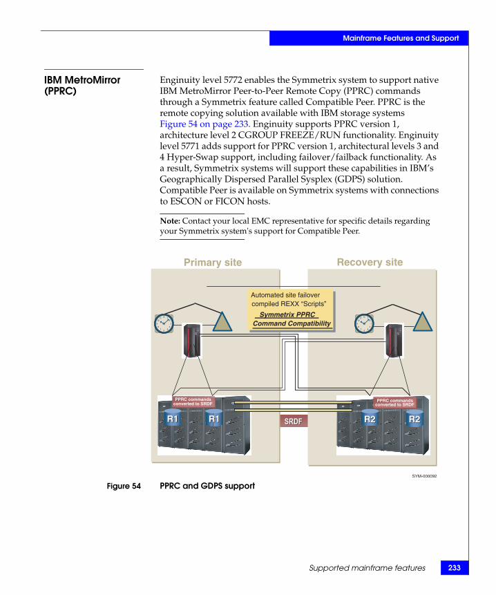
33
Mainframe Features and Support
Supported mainframe features 2
IBM MetroMirror (PPRC)
Enginuity level 5772 enables the Symmetrix system to support native IBM MetroMirror Peer-to-Peer Remote Copy (PPRC) commands through a Symmetrix feature called Compatible Peer. PPRC is the remote copying solution available with IBM storage systems Figure 54 on page 233. Enginuity supports PPRC version 1, architecture level 2 CGROUP FREEZE/RUN functionality. Enginuity level 5771 adds support for PPRC version 1, architectural levels 3 and 4 Hyper-Swap support, including failover/failback functionality. As a result, Symmetrix systems will support these capabilities in IBM’s Geographically Dispersed Parallel Sysplex (GDPS) solution. Compatible Peer is available on Symmetrix systems with connections to ESCON or FICON hosts.
Note: Contact your local EMC representative for specific details regarding your Symmetrix system's support for Compatible Peer.
Figure 54 PPRC and GDPS support
SRDF SRDF
Primary site Recovery site
Automated site failover via compiled REXX “Scripts”
Symmetrix Fully PPRC Command Compliant
Automated site failover compiled REXX “Scripts”
Symmetrix PPRC Command Compatibility
SYM-000092
R1 R1
PPRC commands converted to SRDF
PPRC commands converted to SRDF
PPRC commands converted to SRDF
PPRC commands converted to SRDF
R1 R1 R2 R2 R2 R2

234
Mainframe Features and Support
EMC Symmetrix DMX-4 Product Guide
XRC support Enginuity level 5772 supports IBM’s XRC, level 3 functionality. IBM designed XRC as a host-based disaster recovery and workload migration solution that provides asynchronous copying of zSeries data to a remote data center.
With XRC, a remote site has a point-in-time copy of the source/primary data with the following attributes:
◆ The copy at the remote site is not the most current one; there is a lag between the local and remote copies.
◆ The remote copy’s data is re-startable.
◆ Since this is an asynchronous solution, write operations do not suffer from performance degradation while transferring the data across the link.
XRC provides update sequence integrity through its mechanism of consistency groups, and journal, control, and state data sets. The basic concept is that the System Data Mover (SDM) polls, or receives attention interrupts from, the primary control units it is servicing and retrieves from them all new or updated records.
The SDM then determines the timestamp of the most recent I/O from each control unit in the session. Once these timestamps are determined, SDM selects the smallest of these timestamps as a starting point and forms a group that includes all I/Os received at that time or prior. This set of I/Os constitutes a consistency group that is written to the journal data sets, and then written to the volumes at the recovery site. This is shown in Figure 55 on page 235.
Note: Only Enginuity level 5772 supports XRC functionality. Contact your EMC Sales Representative for specific details regarding your Symmetrix system’s support for XRC.
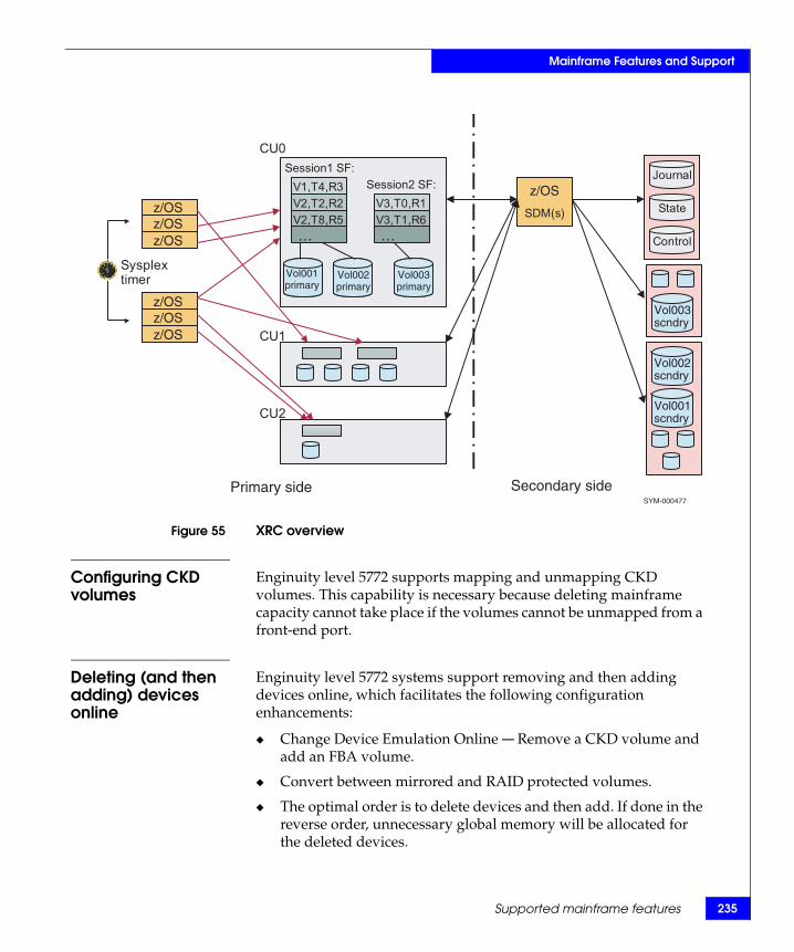
Mainframe Features and Support
Figure 55 XRC overview
Configuring CKD volumes
Enginuity level 5772 supports mapping and unmapping CKD volumes. This capability is necessary because deleting mainframe capacity cannot take place if the volumes cannot be unmapped from a front-end port.
Deleting (and then adding) devices online
Enginuity level 5772 systems support removing and then adding devices online, which facilitates the following configuration enhancements:
◆ Change Device Emulation Online — Remove a CKD volume and add an FBA volume.
◆ Convert between mirrored and RAID protected volumes.
◆ The optimal order is to delete devices and then add. If done in the reverse order, unnecessary global memory will be allocated for the deleted devices.
Sysplextimer
Session1 SF:Session2 SF:
CU0
CU1
CU2
SDM(s)
Journal
State
Control
Primary side Secondary side
V1,T4,R3V2,T2,R2V2,T8,R5…
V3,T0,R1V3,T1,R6…
Vol002scndry
Vol003scndry
Vol001scndry
SYM-000477
Vol001primary
Vol002primary
Vol003primary
z/OS z/OS
z/OS z/OS
z/OS z/OS z/OS
Supported mainframe features 235
236
Mainframe Features and Support
◆ When attempting to add or delete devices, or change protection type of devices, a new minimum cache value will be calculated. In rare cases this new value could prohibit the changes until additional memory is added to the system.
Support for 64 K cylinders
Enginuity level 5772 supports 64 K cylinder CKD devices for operating systems that can exploit it.
FICON Cascading and Open Systems Intermixconfigurations
In addition to the standard direct-connect configuration, Symmetrix DMX FICON models support the use of Cascading and Open Systems Intermix configurations. Cascading can be used to reduce the number of FICON adapters and the amount of intersite cabling required by making use of switch-to-switch communication.
Intermix allows FICON zones to be added to existing Open Systems switches within a site and between sites. These two features help reduce the overall costs while providing greater FICON connectivity, backup, and recovery.
Note: For specific Cascading and Open System Intermix configuration requirements, contact your local EMC Sales Representative.
FICON Cascading configurationsCascading provides greatly enhanced FICON connectivity within local and remote sites through the use of switch-to-switch extensions of the CPU to the DMX FICON network. These cascaded switches communicate over long distances using a small number of high speed lines called ISLs (InterSwitch Links). Up to a maximum of two switches may be connected together within a path between the CPU and the DMX.
Same switch vendors are required for a Cascaded configuration. The EMC and IBM branded McDATA and INRANGE switches are supported in pairs. To support Cascading, each vendor requires specific models, hardware and software features, configuration settings, and restrictions. Specific IBM CPU models, operating system release levels, channel hardware, and microcode levels are also required.
EMC Symmetrix DMX-4 Product Guide

Mainframe Features and Support
FICON Open Systems Intermix configurationsOpen Systems Intermix allows separate FICON zones to be defined within new or existing open systems switches. These switches can also be Cascaded to further enhance connectivity and remote backup and recovery. The EMC and IBM branded McDATA and INRANGE switches are supported. To support Open Systems Intermix, each vendor requires specific models, hardware and software features, configuration settings, and restrictions. Specific IBM CPU models, operating system release levels, channel hardware, and microcode levels are also required.
Supported mainframe features 237

238
Mainframe Features and Support
Error reporting and recoveryThis section discusses the types of errors possible when the Symmetrix system is connected to a mainframe host. It also discusses error handling techniques and an error recovery summary.
Types of errors There are several types of errors associated with data storage. The error type is indicated in the sense information, and in error messages and reports. You should be aware, however, that the error type doesn't necessarily identify the source or the cause of the problem.
The error types detected by the Symmetrix system include the following:
◆ Data Check — The Symmetrix system has detected an error in the bit pattern read from the disk. Data checks are due to hardware problems when writing or reading data, media defects, or random events.
◆ System or Program Check — The Symmetrix system has rejected the command. This condition is attributed to the construction of the channel program. This type of error is indicated to the processor and is always returned to the requesting program.
◆ Overrun — The Symmetrix system cannot receive data at the rate it is transmitted from the host system. This error indicates a timing problem. Resubmitting the I/O operation usually corrects this error.
◆ Equipment Check — The Symmetrix system has detected an error in hardware operation.
Temporary andpermanent errors
Whenever the Symmetrix system detects a data or equipment error, either the Symmetrix system or the host operating system will attempt to recover from the error, depending on the situation and the type of hardware involved. Error recovery can be temporary or permanent.
An error is temporary if the Symmetrix system or the host operating system can recover from the error successfully. The application is not notified of a temporary error. Temporary errors recovered within the Symmetrix system are not listed in the error report unless its internal soft error threshold has been exceeded. Temporary errors recovered by the operating system are logged by the host Error Recovery Procedures (ERP). When requested, the Symmetrix system generates sense bytes and sends them to the operating system. These sense bytes define the error.
EMC Symmetrix DMX-4 Product Guide
Mainframe Features and Support
An error is permanent from a system view if neither the host operating system nor Symmetrix system can recover from the error condition. For example, a channel director may cause a data check error. That data check is permanent to the system and is recorded in the error recording dataset (ERDS) as a permanent path error.
However, if the host system retries the read from an alternate path, and the data is read successfully from the Symmetrix system, the system does not notify the application of the error, so the error is not permanent to the application. If the read on the alternate path was not successful, the data check is permanent from both the system and application points of view.
Recoverability byerror type
An error is recoverable if the application does not see it as a permanent error.
Data checkWhen data is written, the Symmetrix system records check bytes with the data to enable data check detection. These are the error checking and correction (ECC) bytes. These bytes often provide sufficient information for the Symmetrix system to reconstruct the data should an error occur. When the Symmetrix system reconstructs the data using the ECC bytes, the data check is ECC-correctable. ECC-correctable data checks are always recoverable. The Symmetrix system relocates the block as necessary.
When the Symmetrix system cannot reconstruct the data using the ECC bytes, the data check is ECC-uncorrectable. In this case, the Symmetrix system retries the I/O operation. If the retry is unsuccessful, the data check is uncorrectable. This appears as a permanent error to the Symmetrix system.
For Symmetrix systems protected by mirroring, the data check is not reported to the application. The data is provided to the host through the protection mechanism (mirroring) and the Symmetrix system places a remote service call.
ICKDSF control statementFor an uncorrectable data check, on an unprotected Symmetrix system, use the following device support facilities (ICKDSF) control statement to reformat the home address and record zero of the track.
Note: Do not use ICKDSF to assign alternate tracks in the classic IBM manner since no alternate will be assigned.
Error reporting and recovery 239

240
Mainframe Features and Support
Note: This control statement may require an operator response to permit purging of datasets on the volume. Refer to the IBM ICKDSF User's Guide and Reference for more information.
CAUTION!All data remaining on the tracks operated on by this control statement will be DESTROYED. Restore the data from your most recent backup. Using any other means to reallocate data will affect data integrity.
Enter the following ICKDSF control statement to reassign the defective tracks:
INSPECT UNIT(ccuu)|SYSNAME(sysxxx)|DDNAME (ddname)
DEVTYPE(3380/3390) VERIFY (serial) NOPRESERVE NOASSIGN NOMAP -
TRACKS((cyl,head),...)
Specify the desired (cyl,head) in decimal notation, or as (X'cyl',X'head') if hex notation is desired.
Overrun errors and equipment checksWhen an overrun or equipment check is detected, the host system retries the operation. If the operation is successful on the retry, the error is recorded as recoverable. If the retry is unsuccessful, the error is recorded as unrecoverable.
Error reporting The Symmetrix system reports error conditions to the host and to the EMC Customer Support Center through its Autocall feature. The Symmetrix system presents a unit check status in the status byte to the channel whenever it detects an error condition such as a data check, command reject, overrun, or equipment check.
Unit check status The Symmetrix system also presents a unit check status (environmental-data present) whenever it detects an environmental violation. The Symmetrix system runs a series of internal tests on its components at least once every 24 hours and monitors critical components continuously. It also runs these tests when initially powered up or when a software re-set has occurred. These tests check for a low battery charge or AC power failure, or redundant
EMC Symmetrix DMX-4 Product Guide

Mainframe Features and Support
component failure such as the failure of one device in a mirrored pair or the activation of dynamic sparing.
Environmental testserror flag
If, while running its environmental tests, the Symmetrix system detects an error condition, it sets a flag to indicate a pending error and presents a unit check status to the host on the next I/O operation. The Symmetrix system then schedules the test that detected the error condition to be rerun more frequently. (Each test has specific deltas to regulate its execution.) If a device-level problem is detected and reported, subsequent failures of that device are not reported until the failure is fixed. If a second type of failure is detected for a device while there is a pending error-reporting condition in effect, the Symmetrix system reports the pending error on the next SIO and then the second error.
Host sense data When the Symmetrix system presents a unit check status, the host retrieves the sense data from the Symmetrix system and, if logging action has been requested, places it in the Error Recording Data Set (ERDS). The EREP (Environment Recording, Editing, and Printing) program prints the error information. The sense data identifies the condition that caused the interruption and indicates the type of error and its origin. The format of the sense data may be found in the appropriate IBM reference manuals. For interpretation of the EREP reports, the appropriate IBM manual should be consulted.
Service alerts The Symmetrix system reports the exception conditions listed in Table 31 on page 242. Event messages to the host as Service Alerts. In 2105, 2107, or 3990 controller emulations, the returned sense data is in SIM format. In both cases, the code listed will be contained in sense bytes 22 and 23. These messages are reported across all logical paths to the device experiencing the error.
Symmetrix message reporting has been split into four levels of importance for customer convenience. Select the level that best suits your environment. This is done on the INIT screen of Symmwin by Customer Service.
Symmetrix DMX now supports SIM Severity Reporting. With severity reporting, you have control of which severities are reported to the MVS console and which ones are not reported. All SIM severities by default are reported to EREP so there’s always a report of the error even if it’s not reported to the MVS console. The default value in Symmwin is “Only Acute and Serious and Moderate (default).” This will report all SIM Acute, Serious, and Moderate Alerts to the MVS console with all the Service Alerts sent only to EREP.
Error reporting and recovery 241

242
Mainframe Features and Support
The definitions are as follows:
◆ Service alert: No system or application performance degradation is expected. No system or application outage has occurred.
Examples:
• 0462 M1 resynced to M2 device• 0479 Environmental cable missing• 047F PC successfully dialed home to report an error
◆ Moderate alert: Performance degradation is possible in a heavily loaded environment. No system or application outage has occurred.
Examples:
• 046D RDF group has lost links• 0476 No connection between PC and system
◆ Serious alert: A primary I/O subsystem resource is disabled. Significant performance degradation is possible. System or application outage may have occurred.
Examples:
• 0473 Mirror device not ready for periodic test• 0472 Alarm signal set
◆ Acute alert: A major I/O subsystem resource is disabled, or damage to the product is possible. Performance may be severely degraded. System or application outage may have occurred
Examples:
• 0470 Temperature problems• 047A AC line problem detected• 0477 PC failed to call home due to communication problems• 04E0 Communication problem
Table 31 Environmental errors reported as SIM messages (1 of 3)
Hex code Severity alert Description SIM ref code
0453 Remote Service Syscall EMC transfer poll from host. PC call home. 1453
0454 Service Too many suspend/halt chains, switching to ADP-WP. Call home probably MVS PAGE DATA SET.
E454
0460 Serious A dynamic spare was automatically invoked by a DA. E460
0461 Service M2 is resynced with M1 device (happens after M2 is brought back to ready). E461
0462 Service M1 is resynced with M2 device (happens after M2 is brought back to ready). E462
EMC Symmetrix DMX-4 Product Guide

43
Mainframe Features and Support
Error reporting and recovery 2
0463 Serious One of the disk adapters failed into IMPL Monitor. 2463
0464 Service Migration has completed the migration for all migration devices. E464
0465 Service Device resync process has started. E465
0466 Service A dynamic spare was automatically invoked by a DA for an RDF R2 device on the other box.
E466
0467 Moderate RDF ERROR reported across the link from the other box. E467
0469 Service Fibre Channel Optical Module problem (env_test8). E469
046B Service Event trace running in excess of 30 days. E46B
046D Moderate RDF GROUP is lost (no links). E46D
046E Service RDF GROUP is up. E46E
0470 Acute Temperature problems (env_test0). 2470
0471 Serious 90% of log devices are in use. 2471
0472 Serious Alarm signal set (env_test4). 2472
0473 Serious Mirror device not ready at time of periodic test (env_test9). E473
0474 Serious Mirror device is write disable at time of periodic test (env_test9). E474
0475 Serious One of the mirror 2 devices not ready (env_test9). E475
0476 Moderate No connection between PC and system for extended period of time (env_test7).
2476
0477 Remote Failed PC failed to call home due to communications problems. 1477
0478 Moderate 12 volt should be on during FLASH ERASE (env_test1). 2478
0479 Service Environmental cable missing (env_test2). 2479
047A Acute AC line problems detected (env_test3). 247A
047C Acute Log device with user data is not ready. 247C
047D Moderate RA link lost for the group. E47D
047E Service RDF link is operational after previous failure. E47E
047F Remote Service PC successfully called home to report an error. 147F
04AF Acute Power Zone Missing. 24AF
Table 31 Environmental errors reported as SIM messages (2 of 3)
Hex code Severity alert Description SIM ref code

244
Mainframe Features and Support
Operator messages On z/OS, SIM messages will be displayed as IEA480E Service Alert Error messages. They have the format shown in Figure 56 on page 244 and Figure 57 on page 245.
Figure 56 z/OS IEA480E service alert error message format (AC power failure)
04CA Moderate SRDF/A drops with reason codes 50, 60, or 62.
04D1 Remote Service Remote connection established. Remote control connected. 14D1
04D2 Remote Service Remote connection closed. Remote control rejected. 14D2
04D3 Service Flex filter problems. 24D3
04D4 Remote Service Remote connection closed. Remote control disconnected. 14D4
04DA Service Problems with task/threads. 24DA
04DB Service SYMPL script generated error. 24DB
04DC Service PC related problems. 24DC
04E0 Remote Failed Communications problems. 14E0
04E1 Service Problems in error polling. 24E1
04F1 Moderate Internal SPS fault. 24F1
04F2 Moderate Internal SPS fault. 24F2
04F3 Moderate No communication to disconnect SPS. 24F3
Table 31 Environmental errors reported as SIM messages (3 of 3)
Hex code Severity alert Description SIM ref code
*IEA480E 1903,SCU,ACUTE ALERT,MT=2105,SER=0507-00025, REFCODE=247A-0000-0000
247A = AC line failure or interruption SYM-001083
EMC Symmetrix DMX-4 Product Guide

45
Mainframe Features and Support
Error reporting and recovery 2
Figure 57 z/OS IEA480E service alert error message format (mirror-1 volume in “not ready” state)
Note: All host channel paths to that device (target volume) will report this error message. Therefore, this message may appear several times.
The Symmetrix system also reports events to the host and to the service processor. These events are:
◆ The mirror-2 volume has synchronized with the source volume.
◆ The mirror-1 volume has synchronized with the target volume.
◆ Device resynchronization process has begun.
On z/OS, these events are displayed as IEA480E Service Alert Error messages. They have the format shown in Figure 58 on page 245 and Figure 59 on page 246.
Figure 58 z/OS IEA480E service alert error message format (mirror-2 resynchronization)
*IEA480E 1900,DASD,SERIOUS ALERT,MT=2105,SER=0507-00025,REFCODE=E473-0000-7B01,VOLSER=LSJ13B,ID=01
Number of errors = 01
Channel address = 7B
SYM-001084
E473 = Mirror-1 volume in “Not Ready” stateChannel address of the “Not Ready” device
Note:
*IEA480E 0D03,SCU,SERVICE ALERT,MT=3990-3,SER=,REFCODE=E461-0000-6200
Channel address of the synchronized device
E461 = Mirror-2 volume resynchronized with Mirror-1 volume

246
Mainframe Features and Support
Figure 59 z/OS IEA480E service alert error message format (mirror-1 resynchronization)
EREP reports The Environmental Record Editing and Printing (EREP) program is an applications program that runs under the z/OS, VM, and VSE operating systems. EREP helps you monitor the functioning of various units in your system such as the processor, I/O devices, controller, and channels by supplying information on errors that have occurred in these components. When an error occurs, the operating system creates a record from the data captured by the hardware or software and writes it in the Error Reporting Dataset (ERDS). EREP reads records directly from the ERDS and processes them to produce the report or reports you request.
EREP error records Error records processed by EREP are described in detail in the IBM EREP manual.
Note: Refer to the IBM EREP user's guide and reference for the formats of these records.
*IEA480E 0D03,SCU,SERVICE ALERT,MT=3990-3,SER=,REFCODE=E462-0000-6200
Channel address of the synchronized device
E462 = Mirror-1 volume resynchronized with Mirror-2 volume
EMC Symmetrix DMX-4 Product Guide

Mainframe Features and Support
EREP uses the information in these records to produce many types of reports. There are three System Exception Reports applicable to disk media errors with the Symmetrix system. These reports are listed below in the order you use them to identify and handle a media error situation:
◆ System error summary (Part 2) — This report lists permanent I/O errors (data or equipment checks) and identifies each error by job name and time.
◆ Subsystem exception DASD — This report lists accumulated permanent and temporary I/O errors.
◆ DASD data transfer summary — This report presents details on data checks.
Note: Refer to the IBM EREP User's Guide and Reference for information on how to define report requests to meet your needs.
Error handling As part of your routine maintenance procedure, you should generate System Exception Reports daily. From these reports, you can determine whether errors are permanent or temporary, the number of errors that have occurred, and their frequency.
If your system reports permanent errors occurring on the Symmetrix system, save the Subsystem Exception DASD report output and contact your EMC Customer Engineer.
If your system reports that temporary data check errors are occurring on the Symmetrix system, and you consider the number of temporary errors for a volume to be excessive, notify your EMC Customer Engineer.
Table 32 on page 247 describes the error handling process you should follow for the Symmetrix system.
Table 32 Error handling steps
Step Task Tools Actions
1 Detect error occurrence System Error Summary (Part 2) report (permanent errors)Subsystem Exception DASD report (temporary errors)
If permanent error, or if temporary error requires investigation, perform step 2.
2 Determine source of errors using EREP
Subsystem Exception DASD report If the source is hardware, call the EMC Customer Engineer.
Error reporting and recovery 247

248
Mainframe Features and Support
Detecting the error Review the System Error Summary (Part 2) to determine if permanent errors are occurring on the Symmetrix system. This report lists permanent I/O errors in sequence according to the time they occurred. Also review the Subsystem Exception DASD report. This report highlights problems related to data storage that may need further investigation. It gives the number and frequency of both permanent and temporary errors.
You can use this information to defer further handling of a particular error based on its recoverability status, location, and frequency, or take immediate action to correct the error source.
Determining the error source
CAUTION!Permanent data errors with a probable failing unit of VOLUME require your IMMEDIATE attention!
If the System Error Summary (Part 2) and Subsystem Exception DASD reports indicate problems with a Symmetrix device, review the Subsystem Exception DASD report to determine the failing component. This report lists error information by volume. It identifies the failing volume, the track location of the failure, the sense information received from the Symmetrix system at the time of the last failure, and the permanent and temporary error counts on that device.
EMC Symmetrix DMX-4 Product Guide

Mainframe Features and Support
Sense byte information
Note: The information presented in this chapter is only applicable to Symmetrix drives connected to mainframe hosts.
The Symmetrix system presents a unit check status in the status byte to the channel whenever it detects an error condition. The error condition can be one of the error types associated with data such as a data check, command reject, overrun, or equipment check.
The channel issues a sense command to retrieve the sense data from the Symmetrix system. The host places the sense data in the Error Recording Dataset (ERDS) where the EREP subsequently uses it for its reports.
Sense byte error data may also appear on the system operating console. The format of the error data reported to the operator console depends on your operating system. Sense byte data at the host is presented in 24-byte compatibility mode or 32-byte mode for 3990 emulation.
Console error messages
Figure 60 on page 249 is an example of a typical z/OS console error message for 24-byte sense data.
Figure 60 Typical console error message
The unit status and channel status (CSW characters) indicate why the operation terminated. The unit status is bits 32–39 in the CSW (370 mode) and bits 0–7 of Word 2 of the SCSW (XA and ESA mode). The
IOS0001xxx,xx,xxx-xxx,xx,xxxx,xxx-xxx,xxx-xxx,xxxxxx,xxxxxxxx
Device number
Channel path ID
Error description (12 characters)
Command code (2 characters)
CSW status (4 characters:0-1 - Unit status, 2-3 = Channel status)
Sense data (4 to 48 characters)
Seek address (12 characters)
Volume ID (6 characters)
Job ID (8 characters)
Sense byte information 249

250
Mainframe Features and Support
channel status is bits 40–47 in the CSW (370 mode) and bits 8–15 of Word 2 of the SCSW (XA and ESA mode).
Unit status bits Table 33 on page 250 lists and describes the unit status bits.
Channel status bits Table 34 on page 250 lists and describes the channel status bits.
Table 33 Unit status bits
370 XA, ESA Meaning
Bit 32 Bit 0 Attention — READY status when set in conjunction with Device End and Unit Exception.
Bit 33 Bit 1 Status modifier — When set with Unit Check, indicates a usual condition, command retry; when set with Busy, indicates the Symmetrix system is busy; when set with Device End, next CCW has been skipped.
Bit 34 Bit 2 Control-unit end — Symmetrix no longer busy.
Bit 35 Bit 3 Busy — If Status Modifier clear, the drive is busy; if Status Modifier set, the channel director is busy.
Bit 36 Bit 4 Channel end — Data or command transfer to/from channel is complete.
Bit 37 Bit 5 Device end — Device operation complete.
Bit 38 Bit 6 Unit check — Symmetrix system detected an error condition.
Bit 39 Bit 7 Unit exception — EOF on addressed track during a Read R0, Read IPL, or Read CKD, or Write Key Data or Write Data operation. If Attention and Device End set, indicates a READY status.
Table 34 Channel status bits
370 XA, ESA Meaning
Bit 40 Bit 8 Program-controlled interruption (PCI) — CCW specified interrupt occurred.
Bit 41 Bit 9 Incorrect length — Number of bytes transferred were not equal to number of bytes specified by CCW.
Bit 42 Bit 10 Program check — CCW programming error.
Bit 43 Bit 11 Protection check — Channel attempted to address a storage area prohibited by a protection key.
Bit 44 Bit 12 Channel-data check — Incorrect parity.
Bit 45 Bit 13 Channel-control check — Channel hardware error.
Bit 46 Bit 14 Interface-control check — Invalid signal from the Symmetrix system (invalid signal sequence, overly slow response, or parity error on Bus In).
Bit 47 Bit 15 Chaining check — Channel overrun during input operation.
EMC Symmetrix DMX-4 Product Guide

Mainframe Features and Support
Note: You can find a detailed description of these status bits in the appropriate IBM Principles of Operation.
Host sense byte data formats
Sense byte formats are found in the IBM reference manual appropriate for the specific Symmetrix system emulation.
Sense byte information 251

252
Mainframe Features and Support
EMC Symmetrix DMX-4 Product Guide

AInvisible Body Tag
This appendix contains the specifications of the Symmetrix DMX-4 system:
◆ Storage control.................................................................................. 254◆ Physical data ..................................................................................... 263◆ Environmental data ......................................................................... 265◆ Power and cooling data................................................................... 269◆ Electrical specifications and power requirements....................... 270
Symmetrix DMX-4Specifications
Symmetrix DMX-4 Specifications 253

254
Symmetrix DMX-4 Specifications
Storage controlEmulation 3990-6, 2105, 2107, and FBA
Channel speeds Up to 17 MB/s ESCON channelUp to 4 Gb/s FICON channelUp to 4 Gb/s Fibre ChannelUp to 1 Gb/s iSCSI channelUp to 1 Gb/s GigE remote channelUp to 1 Gb/s GigE IPv4/v6 (IPsec capable)
Storage capacities The following tables outline the minimum and maximum disk capacities for the DMX-4 systems.
Tables 35 through 41 describe the DMX-4 disk capacities. The capacities are presented based on the disk drive capacities of 73 GB, 146 GB, 300 GB, 400 GB, and 450 GB Fibre Channel drives, 73 GB and 146 GB Flash drives, 500 GB, and 1 TB SATA II drives, and these methods of data protection:
◆ Mirroring (RAID 1) ◆ RAID 5 (3+1) or (7+1) ◆ RAID 6 (6+2) or (14+2)
Note: The TB values shown in Tables 35 through 41 are based on 1 TB = 1000 * 1000 * 1000 * 1000 bytes.
A Symmetrix DMX-4 reserves two SFS logical volumes consisting of 6,140 cylinders each (slightly less than 6 GB). These volumes are protected using mirroring, consuming slightly less than 24 GB total physical space.
For each pair of disk directors in a DMX-4 system, 160 GB of total capacity is reserved for vaulting data from memory during system powerdown.
Actual usable capacity may vary depending on configuration and data protection types used.
EMC Symmetrix DMX-4 Product Guide

Symmetrix DMX-4 Specifications
Table 35 DMX-4 73 GB disk capacities
ItemMinimum capacity
Maximum capacity
Number of drives 96 1,920
Raw capacity
Open systems (TB) 7.04 140.82
Mainframe (TB) 6.95 139.02
Mirrored
Open systems (TB) 3.52 70.41
Mainframe (TB) 3.48 69.51
RAID 5 (3+1)
Open systems (TB) 5.28 105.62
Mainframe (TB) 5.21 104.27
RAID 5 (7+1)
Open systems (TB) 6.16 123.22
Mainframe (TB) 6.08 121.64
RAID 6 (6+2)
Open systems (TB) 5.28 105.62
Mainframe (TB) 5.21 104.27
RAID 6 (14+2)
Open systems (TB) 6.16 123.22
Mainframe (TB) 6.08 121.64
Storage control 255

256
Symmetrix DMX-4 Specifications
Table 36 DMX-4 146 GB disk capacities
ItemMinimum capacity
Maximum capacity
Number of drives 96 1,920
Raw capacity
Open systems (TB) 14.08 281.66
Mainframe (TB) 13.90 278.04
Mirrored
Open systems (TB) 7.04 140.83
Mainframe (TB) 6.95 139.02
RAID 5 (3+1)
Open systems (TB) 10.56 211.24
Mainframe (TB) 10.43 208.53
RAID 5 (7+1)
Open systems (TB) 12.32 246.45
Mainframe (TB) 12.16 243.29
RAID 6 (6+2)
Open systems (TB) 10.56 211.24
Mainframe (TB) 10.43 208.53
RAID 6 (14+2)
Open systems (TB) 12.32 246.45
Mainframe (TB) 12.16 243.29
EMC Symmetrix DMX-4 Product Guide

57
Symmetrix DMX-4 Specifications
Storage control 2
Table 37 DMX-4 300 GB disk capacities
ItemMinimum capacity
Maximum capacity
Number of drives 96 1,920
Raw capacity
Open systems (TB) 28.78 575.54
Mainframe (TB) 28.41 568.15
Mirrored
Open systems (TB) 14.39 287.77
Mainframe (TB) 14.20 284.08
RAID 5 (3+1)
Open systems (TB) 21.58 431.65
Mainframe (TB) 21.31 426.11
RAID 5 (7+1)
Open systems (TB) 25.18 503.60
Mainframe (TB) 24.86 497.13
RAID 6 (6+2)
Open systems (TB) 21.58 431.65
Mainframe (TB) 21.31 426.11
RAID 6 (14+2)
Open systems (TB) 25.18 503.60
Mainframe (TB) 24.86 497.13

258
Symmetrix DMX-4 Specifications
Table 38 DMX-4 400 GB disk capacities
ItemMinimum capacity
Maximum capacity
Number of drives 96 1,920
Raw capacity
Open systems (TB) 38.37 767.39
Mainframe (TB) 37.88 757.54
Mirrored
Open systems (TB) 19.18 383.69
Mainframe (TB) 18.94 378.77
RAID 5 (3+1)
Open systems (TB) 28.78 542
Mainframe (TB) 28.41 542
RAID 5 (7+1)
Open systems (TB) 33.57 542
Mainframe (TB) 33.14 542
RAID 6 (6+2)
Open systems (TB) 28.78 542
Mainframe (TB) 28.41 542
RAID 6 (14+2)
Open systems (TB) 33.57 542
Mainframe (TB) 33.14 542
EMC Symmetrix DMX-4 Product Guide
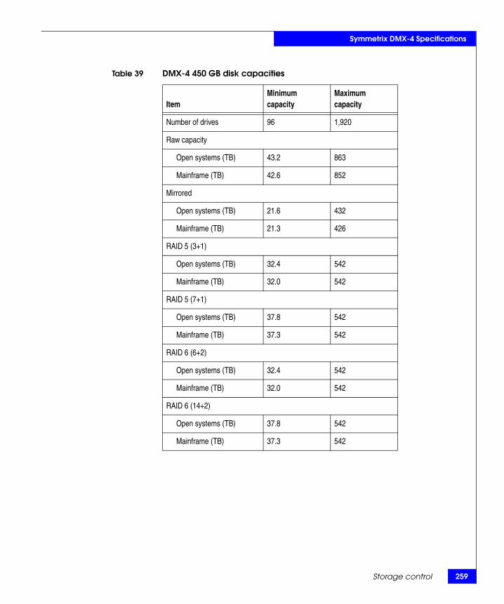
Symmetrix DMX-4 Specifications
Table 39 DMX-4 450 GB disk capacities
ItemMinimum capacity
Maximum capacity
Number of drives 96 1,920
Raw capacity
Open systems (TB) 43.2 863
Mainframe (TB) 42.6 852
Mirrored
Open systems (TB) 21.6 432
Mainframe (TB) 21.3 426
RAID 5 (3+1)
Open systems (TB) 32.4 542
Mainframe (TB) 32.0 542
RAID 5 (7+1)
Open systems (TB) 37.8 542
Mainframe (TB) 37.3 542
RAID 6 (6+2)
Open systems (TB) 32.4 542
Mainframe (TB) 32.0 542
RAID 6 (14+2)
Open systems (TB) 37.8 542
Mainframe (TB) 37.3 542
Storage control 259
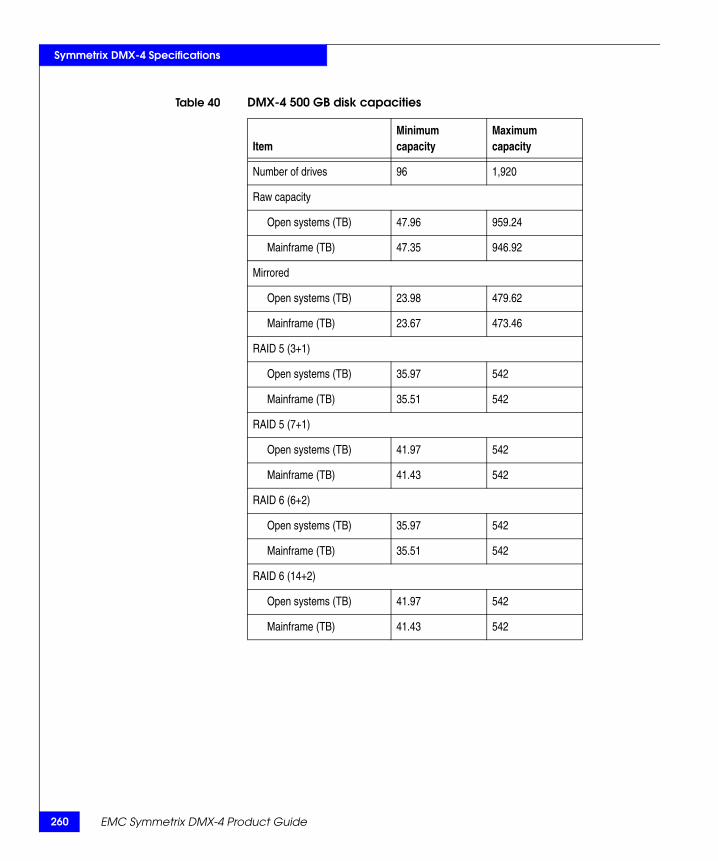
260
Symmetrix DMX-4 Specifications
Table 40 DMX-4 500 GB disk capacities
ItemMinimum capacity
Maximum capacity
Number of drives 96 1,920
Raw capacity
Open systems (TB) 47.96 959.24
Mainframe (TB) 47.35 946.92
Mirrored
Open systems (TB) 23.98 479.62
Mainframe (TB) 23.67 473.46
RAID 5 (3+1)
Open systems (TB) 35.97 542
Mainframe (TB) 35.51 542
RAID 5 (7+1)
Open systems (TB) 41.97 542
Mainframe (TB) 41.43 542
RAID 6 (6+2)
Open systems (TB) 35.97 542
Mainframe (TB) 35.51 542
RAID 6 (14+2)
Open systems (TB) 41.97 542
Mainframe (TB) 41.43 542
EMC Symmetrix DMX-4 Product Guide
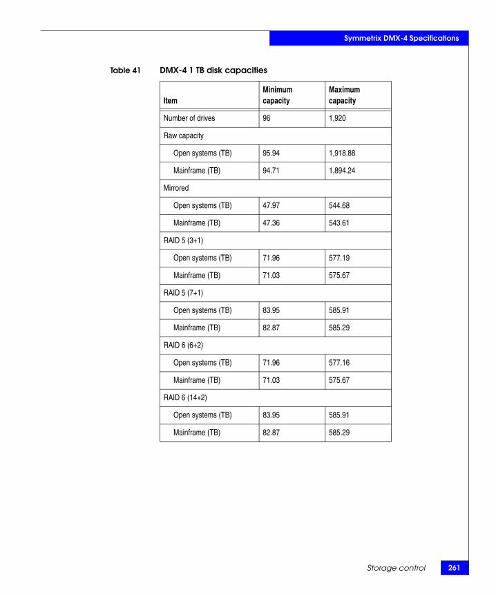
61
Symmetrix DMX-4 Specifications
Storage control 2
Table 41 DMX-4 1 TB disk capacities
ItemMinimum capacity
Maximum capacity
Number of drives 96 1,920
Raw capacity
Open systems (TB) 95.94 1,918.88
Mainframe (TB) 94.71 1,894.24
Mirrored
Open systems (TB) 47.97 544.68
Mainframe (TB) 47.36 543.61
RAID 5 (3+1)
Open systems (TB) 71.96 577.19
Mainframe (TB) 71.03 575.67
RAID 5 (7+1)
Open systems (TB) 83.95 585.91
Mainframe (TB) 82.87 585.29
RAID 6 (6+2)
Open systems (TB) 71.96 577.16
Mainframe (TB) 71.03 575.67
RAID 6 (14+2)
Open systems (TB) 83.95 585.91
Mainframe (TB) 82.87 585.29

262
Symmetrix DMX-4 Specifications
EMC Symmetrix DMX-4 Product Guide
MB/Volumeby emulation type
Bytes/Track Note: Fixed Block Architecture (FBA) capacities are based on 512 bytes per block, 128 blocks per track, and 15 tracks per cylinder.
Bytes/Cylinder Note: Fixed Block Architecture (FBA) capacities are based on 512 bytes per block, 128 blocks per track, and 15 tracks per cylinder.
Cylinders/Volume
Disk drive form factor
3380D emulationa
a. Contact your local EMC Sales Representative for 3380 and 3390-54 emulation availability.
6303380E emulationa 1,2603380K emulationa 1,8913390-1 emulation 9463390-2 emulation 1,8923390-3 emulation 2,8383390-9 emulation 8,5143390-27 emulation 27,8443390-54 emulation a 55,688
3380 emulationsa
a. Contact your EMC Sales Representative for 3380 support.
47,4763390 emulations 56,664FBA 65,536
3380 emulationsa
a. Contact your EMC Sales Representative for 3380 support.
712,1403390 emulations 849,960FBA 983,040
3380D emulationa
a. Contact your local EMC Sales Representative for 3380 and 3390-54 emulation availability.
8853380E emulationa 1,7703380K emulationa 2,6553390-1 emulation 1,1133390-2 emulation 2,2263390-3 emulation 3,3393390-9 emulation 10,0173390-27 emulation 32,7603390-54 emulation 65,520FBA (maximum) 65,520
1-in (2.54 cm) Height (low profile) 3.5-in (8.75 cm) Width

Symmetrix DMX-4 Specifications
Physical dataThe Symmetrix DMX-4 supports configurations of one system bay and from one to eight storage bays. Table 42 on page 263 through Table 44 on page 264 contain the physical data for the DMX-4 system.
Table 42 Physical specifications
Description System bay measurements Storage bay measurements
Dimensions
Height 76.66 in (194.7 cm) a 76.66 in (194.7 cm) a
Width 24.02 in (61.0 cm) 30.20 in (76.3 cm)
Depth 41.16 in (104.5 cm) 41.88 in (106.4 cm)
Clearance for Service and Airflow
Front 42 in (106.7 cm) 42 in (106.7 cm)
Rear 42 in (106.7 cm) 42 in (106.7 cm)
Top 18 in (45.7 cm) 18 in (45.7 cm)
a. This measurement includes the top trim piece. Without the trim piece, the system bay height is 74.90 in. (190.25 cm).
Table 43 Multibay width measurements a
System bay and storage bay configurationsSystem bay and
storage bay widths
System bay and one storage bay 54.47 in (137.9 cm)
System bay and two storage bays 84.92 in (214.8 cm)
System bay and three storage bays 115.37 in (291.7 cm)
System bay and four storage bays 145.82 in (368.6 cm)
System bay and five storage bays 176.27 in (445.5 cm)
System bay and six storage bays 206.72 in (522.4 cm)
System bay and seven storage bays 237.17 in (599.3 cm)
System bay and eight storage bays 267.62 in (676.2 cm)
a. .25 in (.6 cm) added for gap between each bay.
Physical data 263

264
Symmetrix DMX-4 Specifications
EMC Symmetrix DMX-4 Product Guide
Table 44 Multibay weights
Description Weights lbs (kg)Rolling load rates
per tileMaximum rate per caster a
(front)
System bay b 1,626 lbs (737.5 kg) 1,000 lbs (453.6 kg) 600 lbs (272.2 kg)
Storage bay c 2,422 lbs (1,098.6 kg) 1,000 lbs (453.6 kg) 800 lbs (362.9 kg)
System bay and one storage bay 4,048 lbs (1,836.1 kg)
System bay and two storage bays 6,470 lbs (2,934.7 kg)
System bay and three storage bays 8,892 lbs (4,033.3 kg)
System bay and four storage bays 11,314 lbs (5,131.9 kg)
System bay and five storage bays 13,736 lbs (6,230.5 kg)
System bay and six storage bays 16,158 lbs (7,329.1 kg)
System bay and seven storage bays 18,580 lbs (8,427.7 kg)
System bay and eight storage bays 21,002 lbs (9,526.3 kg)
a. Castor weights are measured on a level floor.
b. All system bay weights are calculated for a fully loaded configuration of channel directors, disk directors, global memory directors, and complete power subsystem.
c. All storage bay weights are calculated for a fully loaded configuration of 240 drives.

Symmetrix DMX-4 Specifications
Environmental data
The DMX-4 system requires a period of time to become acclimated to a data center environment. Use the following process to prepare the system for the data center:
◆ Completely remove all packing material from the system. Packaged accessory (Open First) boxes may remain with the system.
◆ Dispose of the packing materials appropriately.
◆ Move the system into its operating environment and allow the system to stabilize in the new environment for up to 16 hours as listed in Table 45 on page 266. If the operating system environments temperature and humidity are unknown then allow the system to stabilize in the new environment for 16 hours.
◆ EMC recommends opening both the front and rear doors of the system to facilitate environmental stabilization.
◆ Do Not apply AC power to the system for at least the number of hours specified in Table 45 on page 266.
Environmental data 265
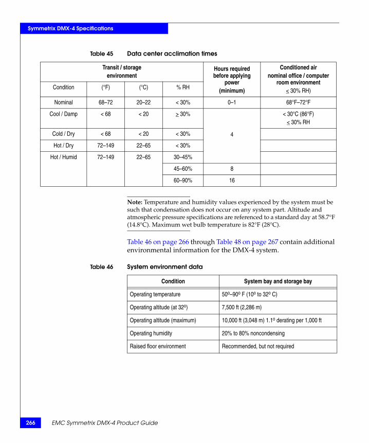
266
Symmetrix DMX-4 Specifications
EMC Symmetrix DMX-4 Product Guide
Note: Temperature and humidity values experienced by the system must be such that condensation does not occur on any system part. Altitude and atmospheric pressure specifications are referenced to a standard day at 58.7°F (14.8°C). Maximum wet bulb temperature is 82°F (28°C).
Table 46 on page 266 through Table 48 on page 267 contain additional environmental information for the DMX-4 system.
Table 45 Data center acclimation times
Transit / storageenvironment
Hours required before applying
power(minimum)
Conditioned airnominal office / computer
room environment< 30% RH)Condition (°F) (°C) % RH
Nominal 68–72 20–22 < 30% 0–1 68°F–72°F
Cool / Damp < 68 < 20 > 30%
4
< 30°C (86°F)< 30% RH
Cold / Dry < 68 < 20 < 30%
Hot / Dry 72–149 22–65 < 30%
Hot / Humid 72–149 22–65 30–45%
45–60% 8
60–90% 16
Table 46 System environment data
Condition System bay and storage bay
Operating temperature 50o–90o F (10o to 32o C)
Operating altitude (at 32o) 7,500 ft (2,286 m)
Operating altitude (maximum) 10,000 ft (3,048 m) 1.1o derating per 1,000 ft
Operating humidity 20% to 80% noncondensing
Raised floor environment Recommended, but not required

67
Symmetrix DMX-4 Specifications
Environmental data 2
Table 47 Shipping and storage environment specifications
Condition System bay and storage bay
Ambient temperature -40o to 149o F (-40o to 65o C)
Temperature gradient 43.2o F/hr (24o C/hr)
Relative humidity 10% to 90% noncondensing
Maximum altitude 25,000 ft (7,619.7 m)
Table 48 Air volume generated
System configuration description English units Metric (SI) units
System bay 1,747 cfm 49 m3/min
Storage bay 1,280 cfm 36 m3/min

268
Symmetrix DMX-4 Specifications
EMC Symmetrix DMX-4 Product Guide
Table 49 Sound power and sound pressure levels
System configuration descriptionSound power levels
A-weighted (B) Sound pressure levels
A-weighted (dB)
Storage baya 7.8 62
System baya 8.4 66
System bay and one storage bay b 8.5 67.4
System bay and two storage bays b 8.6 68.5
System bay and three storage bays b 8.64 69.4
System bay and four storage bays b 8.7 70
System bay and five storage bays b 8.75 70.8
System bay and six storage bays b 8.80 71.3
System bay and seven storage bays b 8.84 71.8
System bay and eight storage bays b 8.88 72.2
a. Average sound power or pressure measurement of the four standby positions per STATSKONTORET.
b. Calculated value.

Symmetrix DMX-4 Specifications
Power and cooling dataThe Symmetrix DMX-4 currently supports configurations of one system bay and from one to eight storage bays as described in Table 50 on page 269.
Note: The totals listed in Table 50 on page 269 are for steady-state operation. After the loss and return of AC power, the batteries in the BBU modules go into recharging mode for up to eight hours and consume 20 percent more power than the totals shown.
Table 50 DMX-4 power consumption and heat dissipation
System configuration description a Total power consumption (kVA) Heat dissipation (Btu/hr)
System bay 6.4 21,850
Storage bay 6.1 19,800
System bay with one storage bay 12.5 41,380
System bay with two storage bays 18.6 61,180
System bay with three storage bays 24.7 80,980
System bay with four storage bays 30.8 100,780
System bay with five storage bays 36.9 120,580
System bay with six storage bays 43.0 140,380
System bay with seven storage bays 49.1 160,180
System bay with eight storage bays 55.2 179,980
a. All system bay values are for a fully loaded configuration of channel directors, disk directors, global memory directors, and complete power subsystem. All storage bay values are for a fully loaded configuration of 16 drive enclosures and 240 disk drives. Contact your local EMC Sales Representative for specific supported configurations.
Power and cooling data 269

270
Symmetrix DMX-4 Specifications
Electrical specifications and power requirementsThis section describes electrical specifications, power cables, connectors, and extension cords for the Symmetrix DMX-4 system bay and each storage bay for North American and international sites. The DMX-4 system uses three-phase power only. The type of input power is determined by the PDP (power distribution panel) required. There are two choices:◆ Three-phase, four-wire, Delta, line-to-line◆ Three-phase, five-wire, WYE, line-to-neutral
Each DMX-4 system bay and storage bay has two power connectors, one affixed to each PDP power cable (Figure 61 on page 270).
Figure 61 Power connections
Zone BAC input
cable B
Cable connectors are shown as they exit the bottom rear
of the DMX-4 bay.
This cabling is internalto the DMX-4 bays.
DMX-4 system bayor storage bay,
rear view
Zone A AC inputcable A
Zone B PDP (Left)
Zone A PDP (Right)
*15 ft. Extensioncord options
*15 ft. Extension cord options
Customer’s powerdistribution unit B
Customer’s powerdistribution unit A
EMC-supplied power cableand connector from the PDP
*Mating connector orcustomer-supplied cable
*Mating connector or customer-supplied cable
EMC-supplied power cable and connector from the PDP
EMC Symmetrix DMX-4 Product Guide

Symmetrix DMX-4 Specifications
Note: The Symmetrix DMX-4 Physical Planning Guide also provides additional planning information for power requirements.
North American power specifications
Table 51 on page 271 describes the electrical specifications for the Symmetrix DMX-4 system bay and storage bays for systems installed in North American, three-phase, Delta environments.
North American extension cords and mating connectors
Each DMX-4 system bay and storage bay has two PDPs with a power cable affixed to each PDP (Figure 61 on page 270). For a North American, three-phase, four-wire, configuration, attached to each PDP power cable is a 50A Hubbell CS8365C or an equivalent 8365 type connector (Delta). Table 52 on page 272 describes the optional EMC extension cords that connect to this Hubbell connector and mating connector options.
Table 51 Electrical specifications, North American, three-phase, four-wire(Delta)
Specification North American three-phase (Delta)
Input nominal voltage a 200–240 VAC L-L nom (208 VAC optimal)
Range 200–240 VAC + 10%
Frequency 50–60 Hz
Circuit breakers 50 A
Power zones Two
Power requirements at customer site (minimum) Two 50 A three-phase drops per bay
a. An imbalance of AC input currents may exist on the three-phase power source feeding the Symmetrix system, depending on configuration. The customer's electrician must be alerted to this possible condition to balance the phase-by-phase loading within the customer's data center.
Electrical specifications and power requirements 271

272
Symmetrix DMX-4 Specifications
Figure 62 EMC model number DMX4-PCBL3DHR cable description
Table 52 Extension line cord, North American, three-phase, four-wire (Delta)
Extension line cord descriptionExtension line cordEMC model number
Mating connector EMC model number, and vendor part number
Three-phase, four-wire, 15 ft line cord with connectors on each end (Delta).• Connector CS8364C mates to the four-wire, DMX-4 system bay or
storage bay power cord connector Hubbell CS8365C or an equivalent 8365 type connector.
• Thomas and Betts/Russellstoll 9P54U2 connector can mate to the optional EMC Russellstoll mating connector or customer-supplied cables.
EMC model number: DMX4-PCBL3DHRFigure 62 on page 272
EMC model number: DMX-ACON3P-50 rated up to 50A.Vendor part number:Russellstoll 9C54U2T
Three-phase, four-wire, 15 ft line cord with connectors on each end (Delta).• Connector CS8364C mates to the four-wire DMX-4 system bay or
storage bay power cord connector Hubbell CS8365C or an equivalent 8365 type connector.
• Connector CS8365C can mate to customer-supplied Hubbell CS8364 or an equivalent type connector or extension cord.
EMC model number: DMX4-PCBL3DHHFigure 63 on page 273
Customer-supplied Hubbell CS8364 or equivalent.
No EMC mating connector available.
P1 P2
CS8364 Russellstoll 9P54U2
Marker, label ID
180.0” +/- 6.0” (15 ft)
CS8364 Russellstoll 9P54U2
Color BLK WHT RED GRN
From P1-X P1-Y P1-Z P1-G
To P2-X P2-Y P2-Z P2-G
Signal L1 L2 L3
GND
SYM-001095 PG
DMX4-PCBL3DHR three-phase, four-wire 50 AMP (200~240 VAC line-to-line) (Delta)
EMC Symmetrix DMX-4 Product Guide

Symmetrix DMX-4 Specifications
Figure 63 EMC model number DMX4-PCBL3DHH cable description
P1 P2
CS8364 CS8365
Marker, label ID
180.0” +/- 6.0” (15 ft)
CS8364 CS8365 Color BLK WHT RED GRN
From P1-X P1-Y P1-Z P1-G
To P2-X P2-Y P2-Z P2-G
Signal L1 L2 L3
GND
SYM-001092 PG
DMX4-PCBL3DHH three-phase three-phase, four-wire 50 AMP (200~240 VAC line-to-line) (Delta)
Y
Z Z X
X
Y
Electrical specifications and power requirements 273
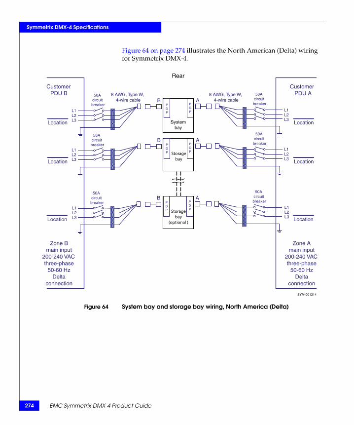
274
Symmetrix DMX-4 Specifications
Figure 64 on page 274 illustrates the North American (Delta) wiring for Symmetrix DMX-4.
Figure 64 System bay and storage bay wiring, North America (Delta)
Customer PDU B
Customer PDU A
P D P
P D P
P D P Storage
bay
P D P
50 A circuit breaker
50 A circuit breaker
50 A circuit breaker
Location Location
Location Location
8 AWG, Type W, 4-wire cable
8 AWG, Type W, 4-wire cable
Zone B main input
200-240 VAC three-phase
50-60 Hz Delta
connection
Zone A main input
200-240 VAC three-phase
50-60 Hz Delta
connection
B A
B A
Systembay
50 A circuit breaker
L1 L2 L3
L1 L2 L3
L1 L2 L3
L1 L2 L3
P D P Storage
bay(optional )
P D P
50 A circuit breaker
50 A circuit breaker
Location Location
B A
L1 L2 L3
L1 L2 L3
SYM-001214
Rear
EMC Symmetrix DMX-4 Product Guide
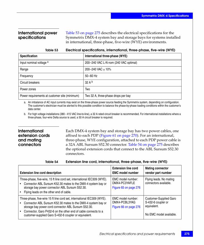
Symmetrix DMX-4 Specifications
International power specifications
Table 53 on page 275 describes the electrical specifications for the Symmetrix DMX-4 system bay and storage bays for systems installed in international, three-phase, five-wire (WYE) environments.
International extension cordsand mating connectors
Each DMX-4 system bay and storage bay has two power cables, one affixed to each PDP (Figure 61 on page 270). For an international, three-phase, WYE configuration, attached to each PDP power cable is a 32A ABL Sursum S52.30 connector. Table 54 on page 275 describes the optional extension cords that connect to the ABL Sursum S52.30 connectors.
Table 53 Electrical specifications, international, three-phase, five-wire (WYE)
Specification International three-phase (WYE)
Input nominal voltage a 200–240 VAC L-N nom (240 VAC optimal)
Range 200–240 VAC + 10%
Frequency 50–60 Hz
Circuit breakers 32 A b
Power zones Two
Power requirements at customer site (minimum) Two 32 A, three-phase drops per bay
a. An imbalance of AC input currents may exist on the three-phase power source feeding the Symmetrix system, depending on configuration. The customer's electrician must be alerted to this possible condition to balance the phase-by-phase loading conditions within the customer's data center.
b. For high voltage installations (380 - 415 VAC line-to-line), a 32 A rated circuit breaker is recommended. For international installations where a three-phase, four-wire Delta source is used, a 50 A circuit breaker is required.
Table 54 Extension line cord, international, three-phase, five-wire (WYE)
Extension line cord descriptionExtension line cordEMC model number
Mating connector vendor part number
Three-phase, five-wire, 15 ft line cord set, international IEC309 (WYE).• Connector ABL Sursum K52.30 mates to the DMX-4 system bay or
storage bay power connector ABL Sursum S52.30.• Flying leads on the other end of cable.
EMC model number:DMX4-PC3YAFLEFigure 65 on page 276
Flying leads. No mating connectors available.
Three-phase, five-wire 15 ft line cord set, international IEC309 (WYE).• Connector ABL Sursum K52.30 mates to the DMX-4 system bay or
storage bay power cord connector ABL Sursum S52.30.• Connector, Garo P432-6 on the other end of cable connects to a
customer-supplied Garo S-432-6 coupler or equivalent.
EMC model number:DMX4-PCBL3YAGFigure 66 on page 276
Customer-Supplied Garo S-432-6 coupler or equivalent.
No EMC model available.
Electrical specifications and power requirements 275

276
Symmetrix DMX-4 Specifications
Figure 65 EMC model number DMX4-PC3YAFLE cable description
Figure 66 EMC model number DMX4-PCBL3YAG cable description
ABL SURSUM K52.30
Marker, label ID
None (pigtail)
180.0” +/- 6.0” (15 ft)
Color BRN BLK GRY BLU
GRN/YEL
From P1-X P1-Y P1-Z P1-W P1-G
Signal L1 L2 L3 N
GND SYM-001094 PG
ABL SURSUM K52.30
P1
DMX4-PC3YFLE three-phase, five-wire, 32 AMP(200~240 VAC line-to-neutral) (WYE)
ABL SURSUM K52.30
Marker, label ID
GARO P432-6
GARO P432-6
180.0” +/- 6.0” (15 ft)
SYM-001096 PG
ABL SURSUM K52.30
P1 P2
Color BRN BLK GRY BLU
GRN/YEL
From P1-X P1-Y P1-Z P1-W P1-G
To P2-X P2-Y P2-Z P2-W P2-G
Signal L1 L2 L3 N
GND
DMX4-PCBL3YAG three-phase, five-wire 32 AMP(200~240 VAC line-to-neutral) (WYE)
EMC Symmetrix DMX-4 Product Guide

Symmetrix DMX-4 Specifications
Figure 67 on page 277 illustrates the international (WYE) wiring with flying leads for the Symmetrix DMX-4 system.
Figure 67 System bay and storage bay wiring with flying leads (WYE)
P D P
Storage bay
P D P
P D P
P D P
Systembay
Rear
Location
Location
Location
Location
Zone Bmain input
200-240 L-N VACthree-phase
50-60 HzWYE
connection
Zone Amain input
200-240 L-N VACthree-phase
50-60 HzWYE
connection
32A circuit
breaker
32A circuit
breaker
32A circuit
breaker
32A circuit
breaker
5 x 6.0mm2 Wire Cable
5 x 6.0mm2 Wire Cable
Customer PDU B
Customer PDU A B A
B A
L1
L2
L3 L4
L1
L2
L3 L4
L1
L2
L3 L4
L1
L2
L3 L4
P D P Storage
bay(optional)
P D P
Location Location
32A circuit
breaker
32A circuit
breaker B A
L1
L2
L3 L4
L1
L2
L3 L4
SYM-001213
Electrical specifications and power requirements 277

278
Symmetrix DMX-4 Specifications
EMC Symmetrix DMX-4 Product Guide

BInvisible Body Tag
This appendix provides instructions for powering the Symmetrix DMX-4 up and down:
◆ Vaulting ............................................................................................. 280◆ Routinely powering up the Symmetrix DMX-4 .......................... 281◆ Powering down the Symmetrix DMX-4 ....................................... 283
Power Sequences
Power Sequences 279
280
Power Sequences
EMC Symmetrix DMX-4 Product Guide
VaultingVaulting allows the Symmetrix system to preserve the contents of cache during a powerdown procedure. When a DMX-4 system is powered down, transitioned to offline, or environmental conditions trigger a vault situation, a vaulting procedure is initiated. This procedure writes all information in cache above a certain point or vault line to the first hypers of designated drives. These are called vault drives. When a system is brought back online, the vault hypers write the stored information back into global memory.
A vault save is initiated under the following circumstances:
◆ System VTOC
◆ When the system is taken offline (DAs taken offline)
◆ Power loss
◆ Whenever the environment monitor determines:
• A loss of vault drives that indicate a “Need to Vault”
• A loss of battery holdup time will indicate a “Need to Vault”
• A loss of BBU battery holdup time will prevent the system from powering up due to a lack of battery power to complete the vault (minimum 300 seconds needed)

Power Sequences
Routinely powering up the Symmetrix DMX-4
CAUTION!The Symmetrix DMX-4 contains no user-serviceable parts. Therefore, the system bay and storage bays should not be opened for any reason by untrained personnel. If the Symmetrix DMX-4 is in need of repair, only qualified personnel familiar with safety procedures for electrical equipment and the Symmetrix DMX-4 should access components inside the unit.
Note: For Symmetrix DMX-4 power connection and configuration requirements, refer to the EMC Symmetrix DMX-4 Physical Planning Guide and the EMC Symmetrix DMX-3 and DMX-4 Best Practices Guide for AC Power Connections. Do not use the following procedures for powering up the Symmetrix DMX-4 for the first time. If you have powered down the Symmetrix DMX-4 for an emergency condition, call the EMC Service Support Center for assistance before powering up the system.
Perform these steps to power up the Symmetrix DMX-4 after it has been routinely powered down by the PDP power switches:
1. On the rear door of each Symmetrix DMX-4 storage bay (Figure 68 on page 282), press the Zone A and Zone B power distribution panel (PDP) power switches to the (|) ON position.
2. On the rear door of the Symmetrix DMX-4 system bay (Figure 68 on page 282), press the Zone A and Zone B PDP power switches to the (|) ON position.
The Symmetrix system begins its initial microcode program load (IMPL) startup procedure.
3. Wait at least 30 minutes for the IMPL procedure to complete.
Note: The actual IMPL procedure time varies by system type and configuration.
Routinely powering up the Symmetrix DMX-4 281

282
Power Sequences
Figure 68 Symmetrix DMX-4 system bay and storage bay power switches
!
EX
P
PR
I
EX
P
PR
I
#
! !
!
EX
P
PR
I
EX
P
PR
I
#
! !
!
EX
P
PR
I
EX
P
PR
I
#
! !
!
EX
P
PR
I
EX
P
PR
I
#
! !
!
EX
P
PR
I
EX
P
PR
I
#
! !
!
EX
P
PR
I
EX
P
PR
I
#
! !
!
EX
P
PR
I
EX
P
PR
I
#
! !
!
EX
P
PR
I
EX
P
PR
I
#
! !
!
EX
P
PR
I
EX
P
PR
I
#
! !
!
EX
P
PR
I
EX
P
PR
I
#
! !
!
EX
P
PR
I
EX
P
PR
I
#
! !
!
EX
P
PR
I
EX
P
PR
I
#
! !
!
EX
P
PR
I
EX
P
PR
I
#
! !
!
EX
P
PR
I
EX
P
PR
I
#
! !
!
EX
P
PR
I
EX
P
PR
I
#
! !
!
EX
P
PR
I
EX
P
PR
I
#
! !
!
EX
P
PR
I
EX
P
PR
I
#
! !
!
EX
P
PR
I
EX
P
PR
I
#
! !
!
EX
P
PR
I
EX
P
PR
I
#
! !
!
EX
P
PR
I
EX
P
PR
I
#
! !
!
EX
P
PR
I
EX
P
PR
I
#
! !
!
EX
P
PR
I
EX
P
PR
I
#
! !
!
EX
P
PR
I
EX
P
PR
I
#
! !
!
EX
P
PR
I
EX
P
PR
I
#
! !
!
EX
P
PR
I
EX
P
PR
I
#
! !
!
EX
P
PR
I
EX
P
PR
I
#
! !
!
EX
P
PR
I
EX
P
PR
I
#
! !
!
EX
P
PR
I
EX
P
PR
I
#
! !
!
EX
P
PR
I
EX
P
PR
I
#
! !
!
EX
P
PR
I
EX
P
PR
I
#
! !
!
EX
P
PR
I
EX
P
PR
I
#
! !
!
EX
P
PR
I
EX
P
PR
I
#
! !
ON I
OFF O
ON I
OFF O
ON I
OFF O
ON I
OFF O
ON I
OFF O
ON I
OFF O
PS8 PS7 PS6 PS5 PS4 PS3 PS2 PS1
ON I
OFF O
ON I
OFF O
ON I
OFF O
ON I
OFF O
ON I
OFF O
ON I
OFF O
PDP (2) (oneon each side of
system bay)
PDP (2) (oneon each side ofstorage bay)
Power Zone BLeft side
Power Zone ARight side
Power Zone BLeft side
Power Zone ARight side
Storage bay rearSystem bay rear
SYM-000976
Powerswitch
Powerswitch
ON I
OFF
O
ONI
OFFO
EMC Symmetrix DMX-4 Product Guide
Power Sequences
Powering down the Symmetrix DMX-4
Note: The Symmetrix DMX-4 is designed to stay powered up for most all situations. Unless there is an emergency situation, first call the EMC Service Support Center for assistance before powering down the Symmetrix DMX-4.
Perform these steps to power down the Symmetrix DMX-4, using the PDP power switches located on the rear door of the system bay and storage bays:
1. Stop all processes to the Symmetrix DMX-4.
Note: If you are powering down the Symmetrix DMX-4 for an emergency condition, stopping all processes to the system is not necessary.
2. On the rear door of the system bay (Figure 68 on page 282), press the Zone A and Zone B PDP power switches to the down (O) OFF position.
3. On the rear door of the storage bays (Figure 68 on page 282), press the Zone A and Zone B PDP power switches to the down (O) OFF position.
Note: The BBU modules automatically turn on when the Symmetrix system detects loss of AC power. The BBU modules will maintain power to the Symmetrix system for up to five minutes while the global memory is vaulted to the vault drives.
Powering down the Symmetrix DMX-4 283

284
Power Sequences
EMC Symmetrix DMX-4 Product Guide
CInvisible Body Tag
This appendix covers the tasks you need to complete when planning or verifying the physical configuration of the Symmetrix DMX-4 or creating I/O addressing schemes:
◆ Planning overview........................................................................... 286◆ Symmetrix DMX-4 power requirements ...................................... 290◆ System placement options .............................................................. 295◆ Planning host connectivity ............................................................. 300◆ Open systems installations ............................................................. 304◆ Mainframe systems installations ................................................... 309
Planning andInstallation
Planning and Installation 285

286
Planning and Installation
EMC Symmetrix DMX-4 Product Guide
Planning overviewThis section provides an overview of the physical details related to planning an installation of the Symmetrix DMX system. It reviews all the necessary installation details performed by EMC personnel and outlines customer responsibilities.
Note: Inform EMC of any labor union-based restrictions or security clearance requirements prior to delivery. For additional information on planning the installation for your Symmetrix DMX-4, the EMC Symmetrix DMX-4 Physical Planning Guide has additional information.
The Symmetrix DMX-4 is designed for installation in a properly equipped computer room with raised floor, controlled temperature and humidity, proper airflow and ventilation, proper power and grounding, system cable routing facilities, fire equipment, and so on. Although a raised floor is not required, it is recommended. One or more planning sessions with your EMC Systems Engineer and Customer Engineer may be necessary to close on all the details related to installation. Table 55 on page 286 lists the responsibility summary at the first planning session.
Symmetrix DMX-4 presite considerations
When planning the installation site for your Symmetrix DMX-4, you will need to meet with your EMC team to complete the presite plan.
The DMX-4 has one system bay and from one to eight storage bays. The system bay, when fully configured can weigh approximately 1,626 lbs (737.5 kg). A single storage bay with 240 disk drives can weigh approximately 2,422 lbs (1,098 kg).
Table 55 Preinstallation responsibility summary
EMC responsibility Customer responsibility
Provide all details necessary for site planning and preparation. Provide an environment that supports safe installation of the Symmetrix DMX-4 and promotes its reliable long-term operation.
Complete and process the Installation Planning Task Sheet and Presite Survey.
Provide appropriate power, cooling and ventilation, humidity control, floor load capability, and service clearances as required.
Arrange for shipment and delivery through appropriate method. Participate in planning sessions as required to ensure a smooth and uncomplicated installation.
Install a properly working system as promised and on schedule. ❏

87
Planning and Installation
Planning overview 2
The maximum weight per system bay caster is 600 lbs and the maximum weight per storage bay caster is 800 lbs. Table 44 on page 264 describes weights for various DMX-4 configurations.
Listed below are some of the pre-installation items to consider before installing the DMX-4 at your site:
◆ Equipment ramp needed if the receiving floor is not level with computer room floor.
Note: All portions of the DMX-4 bays, including optional doors, shall clear ramp and threshold slopes up to 1:10 (rise to run ratio), per Code of Federal Regulations – ADA Standards for Accessible Design, 28 CFR Part 36.
◆ Weight capacities for (Table 44 on page 264): • Service elevator if delivery is to another floor• Computer room floor• The loading dock• The loading dock tailgate
◆ Length of covering required for floor protection.
◆ Direct dial-up phone line (for remote support) within six feet (two meters) of the unit (“Remote support” on page 289).
◆ System cabling and power cabling routing requirements. The Presite Survey completed with the EMC Systems Engineer reports the cable lengths (Fibre Channel or serial) required for each host connection to the Symmetrix DMX-4. From a physical planning perspective, review the routing path(s) from the host(s) to the Symmetrix DMX-4. Resolve any physical access issues before the installation date. Also consider if host cables and power cables require overhead routing. (“Overhead host cable routing” on page 296 and “Overhead power cable routing” on page 296)
◆ Power hardware requirements (“Power and cooling data” on page 269 and “Electrical specifications and power requirements” on page 270).
◆ Environmental requirements — The Symmetrix DMX-4 requires the environmental specifications outlined in “Environmental data” on page 265.
◆ “Physical data” on page 263 provides overall system dimensions and weights for the Symmetrix DMX-4 configurations.

288
Planning and Installation
CAUTION!The customer must make sure the site meets or exceeds the specifications listed.
Layout and space recommendations
Layout and space considerations are found in “System placement options” on page 295.
WARNING
“Floor load-bearing requirements” on page 297 defines important floor load-bearing requirements. Failure to comply with these requirements could result in severe damage to the Symmetrix DMX-4 system, the raised floor, the subfloor and the surrounding infrastructure.
WARNING
Before the Symmetrix DMX-4 bays are rolled into position in the computer room, note how close the wheels are to the edge of the cutout. If the Symmetrix system needs to be relocated, contact the EMC Customer Support Center.
WARNING
When moving the storage bay down an incline, the rear of the cabinet must go first.
When moving the storage bay up an incline, the rear of the bay must go last.
Securing the system If the system is to be secured to the floor for increased stability, use Symmetrix DMX-4 Secure bracket kits. Contact your EMC Sales Representative for more information. See “DMX-4 systems securing kits” on page 43 for additional information.
EMC Symmetrix DMX-4 Product Guide

Planning and Installation
Transportation and delivery guidelines
A Symmetrix DMX-4 delivered within the United States or Canada travels by air-ride truck or van. The Symmetrix DMX-4 system bay and storage bays are shrouded by custom-designed shipping material, crated, and palleted. Integrated shock absorbing casters on which the Symmetrix DMX-4 system bay and storage bay rest facilitate their movement during shipping and installation.
A Symmetrix DMX-4 delivered Internationally normally involves air freight and are, therefore, crated for shipment.
Unless otherwise instructed, the EMC Traffic Department arranges for delivery directly to the customer’s computer room. To ensure successful delivery of the Symmetrix DMX-4, EMC has formed partnerships with specially selected moving companies. These companies have moving professionals trained in the proper handling of large and very sensitive systems. These companies provide the appropriate personnel, floor layments, and any ancillary moving equipment required to facilitate delivery.
Remote support Remote support is an important and integral part of EMC’s Customer Service and Support strategy. Communication between the EMC Customer Support Center and the Symmetrix DMX-4 occurs through the external serial modem connected to the Symmetrix service processor. This feature requires customers to provide a dedicated telephone line (for the modem). The modems do not require external power connections.
Planning for upgrades
When planning for upgrades, consider space, power, and environmental concerns as described in this product guide and the EMC Symmetrix DMX-4 Physical Planning Guide.
Planning overview 289
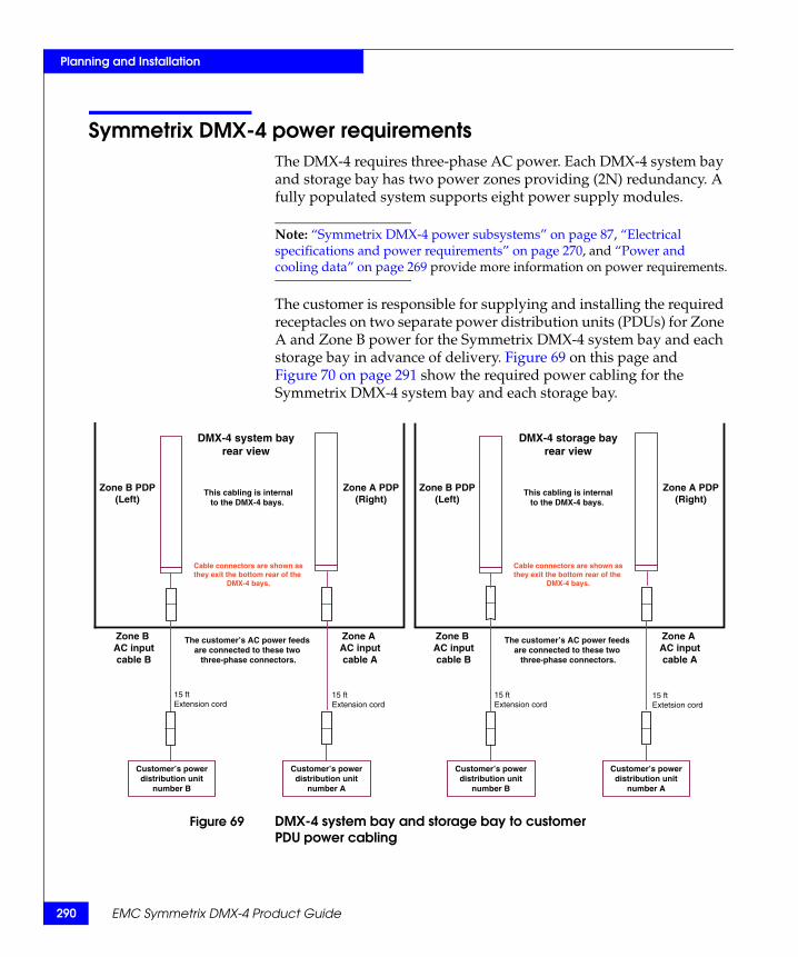
290
Planning and Installation
EMC Symmetrix DMX-4 Product Guide
Symmetrix DMX-4 power requirementsThe DMX-4 requires three-phase AC power. Each DMX-4 system bay and storage bay has two power zones providing (2N) redundancy. A fully populated system supports eight power supply modules.
Note: “Symmetrix DMX-4 power subsystems” on page 87, “Electrical specifications and power requirements” on page 270, and “Power and cooling data” on page 269 provide more information on power requirements.
The customer is responsible for supplying and installing the required receptacles on two separate power distribution units (PDUs) for Zone A and Zone B power for the Symmetrix DMX-4 system bay and each storage bay in advance of delivery. Figure 69 on this page and Figure 70 on page 291 show the required power cabling for the Symmetrix DMX-4 system bay and each storage bay.
Figure 69 DMX-4 system bay and storage bay to customerPDU power cabling
Zone B AC inputcable B
Cable connectors are shown asthey exit the bottom rear of the
DMX-4 bays.
This cabling is internalto the DMX-4 bays.
The customer’s AC power feeds are connected to these two
three-phase connectors.
Customer’s powerdistribution unit
number B
DMX-4 system bayrear view
Zone A AC inputcable A
Zone B PDP (Left)
Zone A PDP (Right)
Zone B AC inputcable B
Cable connectors are shown asthey exit the bottom rear of the
DMX-4 bays.
This cabling is internalto the DMX-4 bays.
The customer’s AC power feeds are connected to these two
three-phase connectors.
DMX-4 storage bayrear view
Zone A AC inputcable A
Zone B PDP (Left)
Zone A PDP (Right)
15 ftExtension cord
15 ftExtension cord
15 ftExtension cord
15 ftExtetsion cord
Customer’s powerdistribution unit
number A
Customer’s powerdistribution unit
number B
Customer’s powerdistribution unit
number A

91
Planning and Installation
Symmetrix DMX-4 power requirements 2
Figure 70 DMX-4 power cabling requirement
Note: The label shown in Figure 70 on page 291, represents the label attached to each cable exiting the Symmetrix DMX-4 system bay and each storage bay. Symmetrix DMX-4 requires two dedicated and isolated AC power feeds that plug directly into the PDPs of the bays. The customer must supply separate PDU connections for proper power redundancy. DMX-4 power redundancy can only be assured at the customer PDU and after. These labels are only to be removed from the cables by the customer’s site electrician. This same label is permanently adhered to the inside of the rear doors of the system bay and the storage bays.
NOI
FF OO
NOI
FF OO
NOI
FF OO
NOI
FF OO
NOI
FF OO
NOI
FF OO
20A_224-300-640
B enoZ)rewoL(
A enoZ)rewoL(
:tnatropmIlaunam noitcurtsni ot refeR
rewoP remotsuC2 ecruoS
rewoP remotsuC1 ecruoS
Two Separate Customer Site PDUs are required.
For site preparation and power connection procedures, refer to the EMC Symmetrix DMX-3 and DMX-4 Best Practices Guide for AC Power Connections.
292
Planning and Installation
EMC Symmetrix DMX-4 Product Guide
Symmetrix touch current compliance
CAUTION!The Symmetrix DMX-4 system bay and the storage bay power supplies should not be connected on the separate Main and Auxiliary circuit panels to differential trip devices. These devices are typically called GFCI (Ground Fault Circuit Interrupter), GFI (Ground Fault Interrupter), ELCB (Earth Leakage Circuit Breaker), or Residual Current Circuit Breakers.
The Symmetrix systems are designated as fixed (stationary) electrical equipment with high earth-leakage markings. The intention is to connect the cabinets to the customer AC supply with the recommended rated current breakers (“Electrical specifications and power requirements” on page 270 has recommended circuit breaker ratings) and the attached cables. These recommended breaker ratings are based on the maximum kW loading of the cabinet and not on the kVA figures of a particular configuration. The kVA values listed in this product guide (“Power and cooling data” on page 269) are intended for air conditioning and utility loading purposes only.
Because the Symmetrix systems are high earth leakage devices, differential trip devices (typically 30 mA) are not recommended due to random activations during utility feed distortions and powerline transients interacting with the cabinet emi noise filters.
These differential devices can be called GFCIs (Ground Fault Circuit Interrupters), GFIs (Ground Fault Interrupters), ELCB (Earth Leakage Circuit Breakers), or other names but typically have trip ratings of 5 mA to 500 mA and are mostly intended for consumer goods rather than fixed devices.
If the Symmetrix bays are correctly grounded to the customer’s AC power source, leakage current should not produce a voltage leading to electrical shock. Serious insulation breakdowns should trip the breakers feeding the cabinet or, preferably, should first clear fuses in individual internal modules closest to the fault.

Planning and Installation
Regulatory compliance
The Symmetrix systems meet regulatory requirements as referenced by the following UL/IEC/EN 60950 3d Edition:
• 5.1.7 Equipment with touch (leakage) current exceeding 3.5 mA
For Stationary Permanently Connected Equipment, or Stationary Pluggable Equipment Type B, having a main protective earthing terminal, if the Touch (Leakage) Current measurements exceed 3.5 mA r.m.s., all of the following conditions apply:
– The r.m.s. Protective Conductor Current shall not exceed five percent of the input current per line under normal operating conditions. If the load is unbalanced, the largest of the three-line (phase) currents shall be used for this calculation.
– To measure the Protective Conductor Current, the procedure for measuring Touch Current is used, but the measuring instrument is replaced by an ammeter of negligible impedance.
– The cross-sectional area of the Protective Bonding Conductor shall not be less than 1.0 mm squared in the path of high Protective Conductor Current.
– A label with similar wording shall be affixed adjacent to the equipment AC MAINS SUPPLY connection:
HIGH LEAKAGE CURRENTEarth connection essential before connecting supply.
The Symmetrix DMX-4 is a Stationary Pluggable Type B system, and has been extensively tested and certified to meet the above standard, including the application of the following warning labels in English and French:
◆ EMC warning label is located inside the rear of the Symmetrix DMX-4 system bay.
◆ EMC warning label is located inside the rear of the Symmetrix DMX-4 storage bay.
Symmetrix DMX-4 power requirements 293
294
Planning and Installation
Choosing a UPS The Symmetrix system is capable of supporting two consecutive five-minute power outages before its BBU modules are depleted.
If you need to extend this time period, you will need to purchase a UPS from a qualified vendor.
EMC neither offers nor recommends any specific UPS suppliers or product type for its customers. This said, EMC uses preferred suppliers for UPS systems in their facilities. Therefore, if you, the customer, are implementing a UPS, EMC recommends the following:
◆ When you are planning the UPS solution for the Symmetrix system and the host system is presently (or is going to be) protected with a UPS, the battery backup time you propose for the Symmetrix UPS solution should match that of the host system.
◆ The Symmetrix system requires independent Zone B and Zone A power feeds.
◆ The UPS should be equipped with an internal output isolation transformer.
◆ The UPS should be installed as a separately derived AC source using neutral and ground wiring to preserve the 2N fault tolerance specification of the Symmetrix power system.
◆ EMC provides kVA power consumption specifications for each system model as described in “Power and cooling data” on page 269. Refer to these specifications when choosing a UPS.
Note: Depending on the power requirements for your Symmetrix system operation, an isolation transformer/stabilizer installed in front of the UPS could further buffer the AC utility environmental factors from reaching the Symmetrix system. To determine if an isolation transformer/stabilizer is needed, consult a licensed electrician and your EMC Customer Engineer.
EMC Symmetrix DMX-4 Product Guide

Planning and Installation
System placement optionsThe Symmetrix DMX-4 system configurations can be installed in several different flooring environments. The system can be installed on a nonraised floor or raised floor environment. Although it is not required, the raised floor environment is the preferred installation environment. “Floor load-bearing requirements” on page 297 lists the floor loading requirements for the Symmetrix DMX-4 installation.
When planning the DMX-4 system placement, EMC recommends positioning the storage bay frame first so that the closed front door aligns with the floor tile edge. The system bay frame is then aligned with the storage bay frames and are bolted together later. When the system bay and all the storage bay doors are closed, the system bay is slightly recessed in relation to the storage bays because the depth of the system bay door is less than the depth of the storage bay doors.
Figure 71 on page 295 shows the placement of a DMX-4 with a system bay and four storage bays on a level nonraised floor.
Note: In a nonraised floor environment, ensure that the room meets environmental specification requirements. “Environmental data” on page 265 contains additional information.
Figure 71 Nonraised floor installation
Front
Rear
41.16 in.104.55 cmIncludesfront and rear doors
41.88 in.106.38 cmIncludesfront and rear doors
Storage bay
System bay
42.00 in. (106.68 cm)Service area (front and rear)
42.00 in. (106.68 cm)Service area (front and rear)
.25 in. (.64 cm) gapbetween cabinets
24.02 in. (61.01 cm)
30.02 in. (76.25 cm)
System placement options 295

296
Planning and Installation
WARNING
Customer must be aware that the load-bearing capacity of the data center floor is not readily ascertainable through a visual inspection of the floor and that the only definitive way to ensure that the floor is capable of supporting the load associated with the Symmetrix DMX-4 storage system is to have a certified architect or the data center design consultant inspect the specifications of the floor to ensure that the floor is capable of supporting the loads specified in Table 44 on page 264. Customer is responsible for insuring that the floor of the data center on which the Symmetric DMX-4 System is to be configured is capable of supporting these loads when the system is configured directly on the data center floor.
WARNING
Failure to comply with these requirements could result in severe damage to the Symmetrix DMX-4 system, the raised floor, the subfloor and the surrounding infrastructure.
NOTWITHSTANDING ANYTHING TO THE CONTRARY IN ANY AGREEMENT BETWEEN EMC AND CUSTOMER, EMC FULLY DISCLAIMS ALL LIABILITY FOR DAMAGE RESULTING FROM CUSTOMER’S NONCOMPLIANCE WITH THE ABOVE FLOOR LOAD-BEARING REQUIREMENTS AND CUSTOMER ASSUMES ALL RISK ASSOCIATED WITH SUCH NONCOMPLIANCE.
Overhead host cable routing
When installing a Symmetrix DMX-4 system configuration, the cabling is handled from the overhead when installing on a nonraised floor or in some instances on a raised floor. To assist in the management of overhead host cable routing, a topside cable routing bracket must be purchased and installed at the rear of the equipment bay.
Overhead power cable routing
If the customer requires power to be supplied from overhead then EMC recommends the power cables be dropped on the outside of the cabinet next to the hinge side of the doors and routed inside the machine.
EMC Symmetrix DMX-4 Product Guide

97
Planning and Installation
System placement options 2
The cable retainer bracket will be removed to allow the cables inside the machine and replaced after cable routing is complete. The cables should be dressed to allow all doors to open freely. The customer is responsible for meeting all of his/her local installation safety requirements.
Note: Although EMC does not require raised floors for routing power cables, it is recommended.
Floor load-bearing requirements
It is recommended but not required that the Symmetrix DMX-4 configuration be installed on a raised floor.
If the system is installed in a raised or nonraised floor environment, customer must ensure that the subfloor or site floor, respectively, is capable of supporting the system weight specified in Table 44 on page 264.
If the system is installed in a raised floor environment, customer must ensure that the raised floor is capable of supporting the system weight. EMC recommends the use of 24 x 24 in heavy-duty, concrete-filled steel floor tiles. If different size or type tile is used, the customer must ensure that the tiles have a minimum load rating that is sufficient for supporting the system weight. To ensure proper physical support of the system, the following requirements, which are based on the use of 24 x 24 in (61 x 61 cm) heavy-duty, concrete-filled steel floor tiles, must be complied with:
◆ Floor must be level.
◆ Floor tiles and stringers must be rated for a minimum static load of 1,600 lbs (725.7 kg) based on two casters of 800 lbs (362.9 kg) each per tile.
◆ Floor tiles must be rated for a minimum of a 1,000 lb (453.6 kg) rolling load.
◆ Floor tiles and stringers must be rated for a minimum static ultimate load of at least 3,000 lbs (1,360.8 kg) per tile.
◆ Floor tile deflection must be minimized with additional pedestal mounts.
◆ Do not position the system bay or storage bays with more than two casters on a single floor tile.
Note: Cutting tiles per specifications as shown on Figure 72 on page 299 will ensure the proper caster placement.

2
Planning and Installation
98 EMC Symmetrix DMX-4 Product Guide
◆ Use or create no more than one floor tile cutout that is no more than 8 in. (20.3 cm) wide by 6 in. (15.3 cm) deep in each 24 x 24 in. (61 x 61 cm) floor tile.
◆ Floor tile cutouts will weaken the tile. Therefore, at least one additional pedestal mount adjacent to the cutout of a tile is recommended. The number and placement of additional pedestal mounts relative to a cutout should be in accordance with the tile manufacturer’s recommendations.
◆ Care should be taken when positioning the bays to make sure that a caster is not moved into a cutout.
◆ Ensure that the weight of any other objects in the data center does not compromise the structural integrity of the raised floor or the subfloor (nonraised floor) of the data center.
WARNING
Customer must be aware that the load-bearing capacity of the data center floor is not readily ascertainable through a visual inspection of the floor and that the only definitive way to ensure that the floor is capable of supporting the load associated with the Symmetrix DMX-4 storage system is to have a certified architect or the data center design consultant inspect the specifications of the floor to ensure that the floor is capable of supporting the system weight specified in Table 44 on page 264. Customer is ultimately responsible for ensuring that the floor of the data center on which the Symmetrix DMX-4 system is to be configured is capable of supporting the system weight, whether the system is configured directly on the data center floor, or the system is configured on a raised floor supported by the data center floor.
Failure to comply with these floor-loading requirements could result in severe damage to the Symmetrix DMX-4 system, the raised floor, subfloor, site floor and the surrounding infrastructure should the raised floor, subfloor or site floor fail.
NOTWITHSTANDING ANYTHING TO THE CONTRARY IN ANY AGREEMENT BETWEEN EMC AND CUSTOMER, EMC FULLY DISCLAIMS ANY AND ALL LIABILITY FOR ANY DAMAGE OR INJURY RESULTING FROM CUSTOMER’S FAILURE TO ENSURE THAT THE RAISED FLOOR, SUBFLOOR OR SITE FLOOR ARE CAPABLE OF SUPPORTING THE SYSTEM WEIGHT AS SPECIFIED ABOVE. CUSTOMER ASSUMES ALL RISK AND LIABILITY ASSOCIATED WITH SUCH FAILURE.

99
Planning and Installation
System placement options 2
Symmetrix DMX-4 configuration floor cutouts
Several DMX-4 configurations are available. Figure 72 on page 299, which illustrates the configuration and the recommended floor tile cutouts for a system bay and eight storage bays. To build a smaller system, remove storage bays as necessary around the system bay. The illustrations assume that the floor tiles are 24 x 24 in. (61 x 61 cm). Also, refer to Chapter 6 in the physical planning guide, that contains tables and configuration illustrations that show bays needed for various DMX-4 configurations.
Figure 72 One system bay and eight storage bays
B B B A B A A A A
Front .25 in. (.64 cm) gapbetween cabinets
42.00 in. (106.68 cm)Service area (front and rear)
42.00 in. (106.68 cm)Service area (front and rear)
Rear Floor tiles24 in. (60.96 cm) sq.
Note: All tiles are 24 in. (60.96 cm) by 24 in. (60.96 cm).
All cutouts are 8 in. (20.32 cm) by 6 in. (15.24 cm).
All cutouts are 9 in. (22.86 cm) from the front and rear of the tile.
All A cutouts are centered on the tiles, 9 in. (22.86 cm) from the front and rear and 8 in. (20.32 cm) from sides.
All B cutouts are centered from front and rear 9 in. (22.86 cm). One side is on the edge of the tile and the other is 16 in. (40.64 cm) from the side.
24.02 in. (61.01 cm)
41.16 in.Includesfront and rear doors
30.02 in. (76.25 cm)

Planning and Installation
Planning host connectivityThe Symmetrix DMX-4 supports open systems connectivity through Fibre Channel and iSCSI channel directors. Mainframe connectivity is supported through ESCON and FICON channel directors. SRDF connections are supported through GigE connections between Symmetrix systems.
Table 17 on page 78 describes the director/adapter combinations currently supported.
Table 56 on page 302 is a planning worksheet for each type of host channel director and the DMX-4 model number.
300 EMC Symmetrix DMX-4 Product Guide

Planning and Installation
Host channel director port assignment worksheetUse the following worksheet Table 56 on page 302 to determine the total quantity of Symmetrix host channel adapter ports that are required.
The GigE-MM description in Table 56 on page 302 refers to GigE or iSCSI configurations.
Note: “Open systems installations” on page 304 provides specific open systems configuration information. “Mainframe systems installations” on page 309 provides specific mainframe information.
Planning host connectivity 301

302
Planning and Installation
Table 56 Symmetrix DMX-4 channel adapter port worksheet (1 of 2)
Director model & number of ports
Quantity of directors
Fibre MMports
Fibre SMports
FICON SMports
FICON MMports
ESCONports
Gig-E MMports
DMX4-80000B
Fibre MM, 8 ports
DMX4-71000B
Fibre MM, 7 ports
Fibre SM, 1 port
DMX4-62000B
Fibre MM, 6 ports
Fibre SM, 2 ports
DMX4-08000B
Fibre SM, 8 ports
DMX4-00004B
FICON SM, 4 ports
DMX4-00040B
FICON MM, 4 ports
DMX4-00400
GigE MM, 4 ports
DMX4-40002B
Fibre MM, 4 ports
FICON SM, 2 ports
DMX4-40200B
Fibre MM, 4 ports
GigE MM, 2 ports
DMX4-60100B
Fibre MM, 6 ports
GigE MM, 1 port
DMX4-00103B
FICON SM, 3 ports
GigE MM, 1 port
EMC Symmetrix DMX-4 Product Guide

Planning and Installation
Director model & number of ports
Quantity of directors
Fibre-MMports
Fibre-SMports
FICON-SMports
FICON-MMports
ESCONports
Gig-E -MMports
DMX4-ESCD8
ESCON, 8 ports
DMX4-00103BS
FICON SM, 3 ports
GigE IPv4/v6 (IPsec capable) MM, 1 port
DMX4-00400BS
GigE IPv4/v6 (IPsec capable) MM, 4 ports
DMX4-40200BS
FIbre MM, 4 ports
GigE IPv4/v6(IPsec capable) MM, 2 ports
DMX4-60100BS
Fibre MM, 6 ports
GigE IPv4/v6 (IPsec capable) MM, 1 port
Fibre MM Fibre SM FICON SM FICON MM ESCON GigE MM
Total all ports
Table 56 Symmetrix DMX-4 channel adapter port worksheet (2 of 2)
Planning host connectivity 303
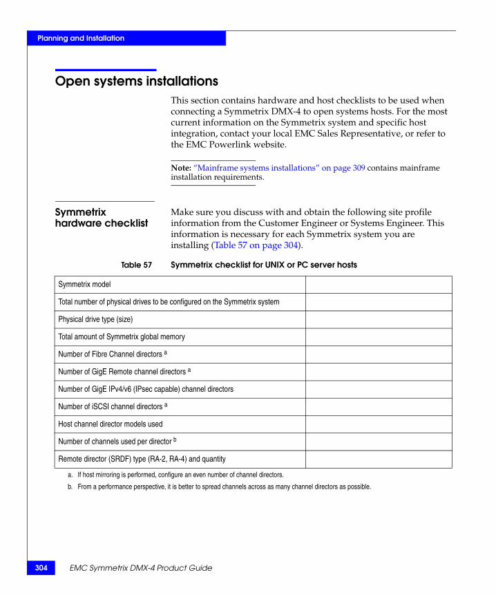
304
Planning and Installation
Open systems installationsThis section contains hardware and host checklists to be used when connecting a Symmetrix DMX-4 to open systems hosts. For the most current information on the Symmetrix system and specific host integration, contact your local EMC Sales Representative, or refer to the EMC Powerlink website.
Note: “Mainframe systems installations” on page 309 contains mainframe installation requirements.
Symmetrix hardware checklist
Make sure you discuss with and obtain the following site profile information from the Customer Engineer or Systems Engineer. This information is necessary for each Symmetrix system you are installing (Table 57 on page 304).
Table 57 Symmetrix checklist for UNIX or PC server hosts
Symmetrix model ❏
Total number of physical drives to be configured on the Symmetrix system ❏
Physical drive type (size) ❏
Total amount of Symmetrix global memory ❏
Number of Fibre Channel directors a ❏
Number of GigE Remote channel directors a ❏
Number of GigE IPv4/v6 (IPsec capable) channel directors ❏
Number of iSCSI channel directors a ❏
Host channel director models used ❏
Number of channels used per director b ❏
Remote director (SRDF) type (RA-2, RA-4) and quantity ❏
a. If host mirroring is performed, configure an even number of channel directors.
b. From a performance perspective, it is better to spread channels across as many channel directors as possible.
EMC Symmetrix DMX-4 Product Guide

Planning and Installation
Host checklist Make sure you discuss with and provide the following host information to the Customer Engineer or Systems Engineer. This information is necessary for each host you are attaching to the Symmetrix system. Make a copy of this form, Table 58 on page 305, for each host you will attach to the Symmetrix system. When you are done, you should have a checklist for each host.
Table 58 UNIX or PC server host checklist (1 of 2)
Host configuration requirements Host 1 Host 2
Host (CPU) vendor and model number. ❏ ❏
Host controller type and model number. ❏ ❏
Memory capacity of host. ❏ ❏
O/S revision level of host. ❏ ❏
I/O rate per second expected per host. ❏ ❏
Type of host (Fibre Channel, iSCSI) channel adapter used on host, type, and model number.
❏ ❏
Is this a clustered environment? Which one? ❏ ❏
Will devices be shared? Which ones? ❏ ❏
Total number of host (Fibre Channel, iSCSI) channel connections per host and to which ports will they attach?
❏ ❏
Specify if any narrow channels used. ❏ ❏
Number of logical devices needed per host (Fibre Channel, iSCSI) channel path.
❏ ❏
Size of volumes required to be visible to host.a ❏ ❏
Total customer-usable data storage required. ❏ ❏
Will host-level mirroring be used, which volumes? ❏ ❏
Does the customer have the recommended number of spares? (EMC order entry)
❏ ❏
Will Symmetrix Mirrored (RAID 1) be used, which volumes? ❏ ❏
Will Symmetrix RAID 5 (3+1) or RAID 5 (7+1) be used, which volumes? (You cannot mix RAID 5 (3+1) and RAID 5 (7+1) volumes on the same Symmetrix system.)
❏ ❏
Will SRDF be used, which volumes? ❏ ❏
Data storage utilization per host.b ❏ ❏
Average transfer size of data. ❏ ❏
Open systems installations 305

306
Planning and Installation
Using raw devices or file systems? ❏ ❏
Size of file system. ❏ ❏
Will data striping be used?What type of data striping package?Will RAID 1/0 be used?
❏ ❏
Partitioning? ❏ ❏
Partition sizes? ❏ ❏
LVM used.c ❏ ❏
What major applications are to be run? ❏
❏
❏
❏
❏
❏
❏
Database used: Oracle/Sysbase/Informix/other? ❏ ❏
Size of database. ❏ ❏
Database release version. ❏ ❏
Supply typical high level database schema and queries. ❏ ❏
Any patches or modifications related to I/O Fibre Channel? ❏ ❏
Additional comments: ❏ ❏
a. This is the volume size needed for each volume visible on the Fibre Channel path.
b. Percentage of available Symmetrix data capacity used by that host.
c. Special attention is required when using a Logical Volume Manager (LVM) or data striping when using hypervolumes. In general, EMC recommends using data striping on the Symmetrix system. Keep in mind that the larger the granularity of the striping, the less effective it becomes.
Table 58 UNIX or PC server host checklist (2 of 2)
Host configuration requirements Host 1 Host 2
EMC Symmetrix DMX-4 Product Guide

Planning and Installation
Available EMC Fibre Channel cables
Table 59 on page 307 lists the Symmetrix Fibre Channel cables currently available from EMC. To obtain these cables, contact your local EMC Sales Representative.
Table 59 EMC Fibre cables—Fibre Channel connect
Multimode Fibre cables—50 micron Single-mode Fibre cables—9 micron
Model number Description Model number Description
FC1M-50MSLC SC/LC-1 meter w/SC coupler FC1M-9MSLC SC/LC-1 meter w/coupler
FC3M-50MSLC SC/LC-3 meter w/SC coupler FC3M-9MSLC SC/LC-3 meter w/coupler
FC5M-50MSLC SC/LC-5 meter FC5M-9MSLC SC/LC-5 meter
FC10M-50MSLC SC/LC-10 meter FC10M-9MSLC SC/LC-10 meter
FC30M-50MSLC SC/LC-30 meter FC30M-9MSLC SC/LC-30 meter
FC50M-50MSLC SC/LC-50 meter FC50M-9MSLC SC/LC-50 meter
FC100M-50MSLC SC/LC-100 meter FC100M-9MSLC SC/LC-100 meter
FC1M-50MLC LC/LC-1 meter N/A N/A
FC3M-50MLC LC/LC-3 meter N/A N/A
FC5M-50MLC LC/LC-5 meter FC5M-9MLC LC/LC-5 meter
FC10M-50MLC LC/LC-10 meter FC10M-9MLC LC/LC-10 meter
FC30M-50MLC LC/LC-30 meter FC30M-9MLC LC/LC-30 meter
FC50M-50MLC LC/LC-50 meter FC50M-9MLC LC/LC-50 meter
FC100M-50MLC LC/LC-100 meter FC100M-9MLC LC/LC-100 meter
Open systems installations 307

308
Planning and Installation
Available EMC GigE/iSCSI cables
Table 60 on page 308 lists the Symmetrix GigE/iSCSI Channel cables currently available from EMC. To obtain these cables, contact your local EMC Sales Representative.
Table 60 GigE/iSCSI channel cables
Model Description Where used
FC5M-62MSLC SC/LC-5 meter For Symmetrix DMX-4 GigE/iSCSI connection to patch panels or Ethernet switches using LC connectors.
FC10M-62MSLC SC/LC-10 meter
FC30M-62MSLC SC/LC-30 meter
FC50M-62MSLC SC/LC-50 meter
FC100M-62MSLC SC/LC-100 meter
FC1M-62MLC LC/LC-1 meter For Symmetrix DMX-4 GigE/iSCSI connection to patch panels or Ethernet switches using LC connectors.
FC3M-62MLC LC/LC-3 meter
FC5M-62MLC LC/LC-5 meter
FC10M-62MLC LC/LC-10 meter
FC30M-62MLC LC/LC-30 meter
FC50M-62MLC LC/LC-50 meter
FC100M-62MLC LC/LC-100 meter
EMC Symmetrix DMX-4 Product Guide

Planning and Installation
Mainframe systems installationsThis section contains hardware and host checklists to be used when connecting a Symmetrix DMX-4 to mainframe systems hosts. For the most current information on the Symmetrix system and specific host integration, contact your local EMC Sales Representative, or refer to the EMC Powerlink website.
Note: “Open systems installations” on page 304 contains open systems installation requirements.
Symmetrix hardware checklist
Make sure you discuss with and obtain the following site profile information from the Customer Engineer or Systems Engineer. This information is necessary for each Symmetrix system you are installing (Table 61 on page 309).
Table 61 Symmetrix checklist for mainframe hosts
Symmetrix DMX-4 model ❏
Total number of physical drives to be configured on the Symmetrix system ❏
Physical drive type (size) ❏
Total amount of Symmetrix global memory ❏
Number of ESCON directors a ❏
Number of FICON directors a ❏
Host channel director models used ❏
Number of channels used per director b ❏
Remote director (SRDF) type (RA-2, RA-4) and quantity ❏
a. If host mirroring is performed, configure an even number of channel directors.
b. From a performance perspective, it is better to spread channels across as many channel directors as possible.
Mainframe systems installations 309

310
Planning and Installation
Available EMC ESCON cables
Table 62 on page 310 lists the Symmetrix DMX-4 ESCON cables currently available from EMC. To obtain these cables, contact your local EMC Sales Representative.
Table 62 ESCON channel cables
Model Description Where used
FC3M-62MSLC SC/LC-3 meter w/SC coupler For Symmetrix DMX-4 ESCON connections to existing 62.5 micron multimode cabling using SC connectors.
FC5M-62MSLC SC/LC-5 meter For Symmetrix DMX-4 ESCON connections to patch panels or ESCON switches using SC connectors.
FC10M-62MSLC SC/LC-10 meter
FC30M-62MSLC SC/LC-30 meter
FC50M-62MSLC SC/LC-50 meter
FC100M-62MSLC SC/LC-100 meter
FC1M-62MLC LC/LC-1 meter For Symmetrix DMX-4 ESCON direct connection or connection to patch panels or ESCON switches using LC connectors.FC3M-62MLC LC/LC-3 meter
FC5M-62MLC LC/LC-5 meter
FC10M-62MLC LC/LC-10 meter
FC30M-62MLC LC/LC-30 meter
FC50M-62MLC LC/LC-50 meter
FC100M-62MLC LC/LC-100 meter
FC3M-LCESCADP LC/ESCON—3 meter with ESCON ST coupler For Symmetrix DMX-4 ESCON connections to existing 62.5 micron cabling using ESCON duplex connectors.
FC3M-MTESCADP MTRJ/ESCON—3 meter with ESCON coupler For connecting Symmetrix 8000 systems, Symmetrix DMX-2, Symmetrix DMX-3, and Symmetrix DMX-4 systems by way of 62.5 micron cabling to IBM directors using new MTRJ connectors.
FC3M-MTLCADP MTRJ/LC—3 meter with LC coupler For connecting Symmetrix DMX-4 systems by way of 62.5 micron cabling to IBM directors using new MTRJ connectors.
EMC Symmetrix DMX-4 Product Guide

Planning and Installation
Available EMC FICON cables
Table 63 on page 311 lists the Symmetrix DMX-4 FICON cables currently available from EMC. To obtain these cables, contact your local EMC Sales Representative.
Table 63 EMC Fibre cables—FICON 9 micron connect
Model number Description
FC1M-9MSLC SC/LC-1 meter w/coupler
FC3M-9MSLC SC/LC-3 meter w/coupler
FC5M-9MSLC SC/LC-5 meter
FC10M-9MSLC SC/LC-10 meter
FC30M-9MSLC SC/LC-30 meter
FC50M-9MSLC SC/LC-50 meter
FC100M-9MSLC SC/LC-100 meter
FC5M-9MLC LC/LC-5 meter
FC10M-9MLC LC/LC-10 meter
FC30M-9MLC LC/LC-30 meter
FC50M-9MLC LC/LC-50 meter
FC100M-9MLC LC/LC-100 meter
Mainframe systems installations 311

312
Planning and Installation
EMC Symmetrix DMX-4 Product Guide

Glossary
This glossary contains terms related to disk storage subsystems. Many of these terms are used in this manual.
Aactuator A set of access arms and their attached read/write heads, which
move as an independent component within a head and disk assembly (HDA).
adapter A board that provides the physical interface between the director and drives (disk adapter), and various host channels (Fibre Channel, iSCSI, GigE, FICON, and ESCON adapters).
ADT Automatic Diagnostic Test.
alternate track A track designated to contain data in place of a defective primary track. See also ”primary track.”
ANSI American National Standards Institute. A standards-setting, nongovernment organization which develops and publishes standards for voluntary use in the U.S.
asynchronoustransmission
Transmission in which synchronization is done on a per-byte basis. The synchronizing handshake is done using REQuest and ACKnowledge signals.
EMC Symmetrix DMX-4 Product Guide 313

314
Glossary
Bbackplane Card that accommodates the channel directors, disk directors, global
memory directors, channel adapters, and the XCM.
battery backup unit(BBU)
Two BBU modules in each BBU assembly. One BBU assembly within the card cage enclosure supplies redundant power to the SPE. Each drive enclosure has a BBU module associated with it that provides redundant power.
bit The smallest unit of computer memory. A bit can hold a value of zero or one.
business continuancevolumes (BCVs)
A standard Symmetrix device with special attributes that allow it to independently support applications and processes, such as backup operations, restore operations, Decision Support operations, and application testing. BCV devices are available through the EMC TimeFinder software.
byte Any 8-bit unit of data storage.
Ccache See ”global memory.”
cache slot Unit of cache equivalent to one track.
channel director The component in the Symmetrix subsystem that interfaces between the host channels and data storage. It transfers data between the channel and global memory.
CCOPY Concurrent Copy Facility used on IBM DASD.
command descriptorblock (CDB)
The structure used to communicate commands from an initiator to a target. This structure may be 6 bytes, 10 bytes, or 12 bytes in size.
Compatible ParallelAccess Volumes
(COM-PAV)
Compatible Parallel Access Volumes is an IBM feature, supported by the Symmetrix unit, that improves response time, resulting in greater resource availability to the host.
controller ID Controller identification number of the director that the disks are channeled to for EREP usage. There is only one controller ID for the Symmetrix unit.
EMC Symmetrix DMX-4 Product Guide

Glossary
Count-Key-Data(CKD)
A data recording format employing self-defining record formats in which each record is represented by a count area that identifies the record and specifies its format, an optional key area that may be used to identify the data area contents, and a data area that contains the user data for the record. CKD can also refer to a set of channel commands that are accepted by a device that employs the CKD recording format.
DDASD Direct access storage device.
data availability Access to user data at all times by the application.
delayed fast write An operation used when there is no room in global memory for the data presented by the write operation. Therefore, the write is delayed until there is room in global memory.
destage The asynchronous write of new or updated data from global memory to disk drive.
device A uniquely addressable part of the Symmetrix subsystem that consists of a set of access arms, the associated disk surfaces, and the electronic circuitry required to locate, read, and write data. See also ”volume.”
device address The hexadecimal value that uniquely defines a physical I/O device on a channel path in an MVS environment. See also ”unit address.”
device form factor Refers to the physical size and shape of a device. Example: 73 GB disk drive is a 1-inch disk drive in a 3.5-inch form factor.
device number The value that logically identifies a disk drive in a string.
device supportfacilities program
(ICKDSF)
A program used to initialize the Symmetrix system at installation and provide media maintenance.
diagnostics System-level tests or firmware designed to inspect, detect, and correct failing components. These tests are comprehensive and self-invoking.
director See ”channel director” or See ”disk director.” .
EMC Symmetrix DMX-4 Product Guide 315
316
Glossary
disk director The component in the Symmetrix subsystem that interfaces between global memory and the drives.
dual-initiator A Symmetrix feature that automatically creates a backup data path to the drives serviced directly by a disk director, if that disk director or the disk management hardware for those devices fails.
Dynamic PathReconnect (DPR)
A function that allows disconnected I/O operations with the Symmetrix system to reconnect over any available channel path rather than be limited to the one on which the I/O operation was started. This function is available only on System 370/XA, System 370/ESA, and System 390/ESA systems.
EEMIF ESCON Multiple Image Facility. Allows sharing of ESCON channels
among logical partitions (LPAR).
Enginuity Enginuity is the operating environment for the EMC Symmetrix Enterprise Storage Platforms. Enginuity provides functional services for both its host Symmetrix systems as well as for a large suite of EMC Storage Application software.
EPO Emergency Power Off.
EREP program Environmental Recording, Editing, and Printing—The program that formats and prepares reports from the data contained in the Error Recording Dataset (ERDS).
error verification The process of reading, checking the error correction bits, and writing corrected data back to the source.
ESA Enterprise System Architecture (mainframe systems only).
ESCON Enterprise Systems Connection.
ESCON director Device that provides a dynamic switching function and extended link path lengths (with XDF capability) when attaching an ESCON channel to a Symmetrix serial channel interface.
ESP Enterprise Storage Platform. Symmetrix ESP is a functional enhancement that allows simultaneous storage and access of mainframe data and open systems data on the same Symmetrix system.
EMC Symmetrix DMX-4 Product Guide
Glossary
Ffast write In the Symmetrix system, a write operation at global memory speed
that does not require immediate transfer of data to disk. The data is written directly to global memory and is available for later destaging.
FBA Fixed Block Architecture. disk drive data storage format using fixed-size data blocks.
Fibre Channel A nominally 2 Gb/s serial data transfer interface technology, although the specification allows data transfer rates from 133 Mb/s up to 4.25 Gb/s. Data can be transmitted and received simultaneously. Common transport protocols, such as Internet Protocol (IP) and Small Computer Systems Interface (SCSI), run over Fibre Channel. Consequently, a single connectivity technology can support high-speed I/O and networking.
FC-AL Fibre Channel Arbitrated Loop. A standard for a shared access loop, in which a number of Fibre Channel devices are connected (as opposed to point-to-point transmissions). Requires a port to successfully negotiate to establish a circuit between itself and another port on the loop.
FC-SW Fibre Channel Switch Fabric. A Fibre Channel network standard where nodes are connected to a fabric topology implemented by one or more switches. Each node's N_Port connects to an F_Port on a switch. Pairs of nodes connected to an FC-SW network can communicate concurrently.
field replaceable unit(FRU)
A component that is replaced or added by service personnel as a single entity.
Frame Data packet format in an ESCON environment.
Ggigabyte (GB) 109 bytes. The GB2 value is based on the convention:
1 GB = 1024 * 1024 * 1024 bytes. The GB10 value is based on the convention: 1 GB = 1000 * 1000 * 1000 bytes. Although these values are expressed differently, their values are equivalent.
EMC Symmetrix DMX-4 Product Guide 317
318
Glossary
global memory Random-access electronic system storage used to retain frequently used data for faster access by the channel.
group The physical disks related to each other for common parity protection when implementing the RAID 5 option.
HHACMP High Availability Clustered Multiprocessing. IBM’s cluster system
developed by CLAM Associates.
head and diskassembly (HDA)
A field replaceable unit in the Symmetrix subsystem containing the disk and actuator.
home address (HA) The first field on a CKD track that identifies the track and defines its operational status. The home address is written after the index point on each track.
hypervolumeextension
The ability to define more than one logical volume on a single physical disk drive making use of its full formatted capacity. These logical volumes are user-selectable in size. The minimum volume size is one cylinder and the maximum size depends on the disk drive capacity and the emulation mode selected.
IICKDSF See ”device support facilities program (ICKDSF).”
identifier (ID) A sequence of bits or characters that identifies a program, device, controller, or system.
IML Initial Microcode Loading.
IMPL Initial Microcode Program Loading.
index marker An indicator for the physical beginning and end of a track.
index point The reference point on a disk surface that determines the start of a track.
IOCP Input/Output Configuration Program.
initiator A SCSI device (usually a host system) that requests an operation to be performed by another SCSI device.
EMC Symmetrix DMX-4 Product Guide

Glossary
I/O device An addressable input/output unit such as a disk drive.
IPL Initial Program Loading.
Kkilobyte (KB) The KB2 value is based on the convention:
1 KB = 1024 bytes.The KB10 value is based on the convention: 1 KB = 1000 bytes.Although these values are expressed differently, their values are equivalent.
Lleast recently used
algorithm (LRU)The algorithm used to identify and make available the global memory space by removing the least recently used data.
link control card(LCC)
Cards located at the rear of each drive enclosure. Each LCC supports and controls one FC loop and monitors the drive enclosure environment. There are two LCCs per drive enclosure.
Logical Unit A physical or virtual device addressable through a target. A physical device can have more than one logical unit.
logical unit number(LUN)
An encoded three-bit identifier for the logical unit of a SCSI device.
logical volume (LV) A user-defined storage device. In the Symmetrix subsystem, for example, the user can define a physical disk drive as one to eight logical volumes.
logical volumemanager (LVM)
Host software responsible for management of the disk subsystems. Interaction with the LVM is done through GUI or through stand-alone commands.
long miss A state when requested data is not in global memory and is not in the process of being fetched.
longitude redundancycode (LRC)
Exclusive OR (XOR) of the accumulated bytes in the data record.
EMC Symmetrix DMX-4 Product Guide 319

320
Glossary
LPAR Logical Partition or Logical Partitioning Mode. Mainframe system function that allows different operating systems to run concurrently in separate logical partitions. See also ”EMIF.”
MMA Multiple Allegiance is an IBM feature, supported by the Symmetrix
system, that improves throughput across a shared storage environment. MA allows more than one I/O from different hosts to access the same device as long as the I/Os do not conflict with each other.
media The disk surface on which data is stored.
megabyte (MB) The MB2 value is based on the convention: 1 MB = 1024 * 1024 bytes.The MB10 value is based on the convention: 1 MB = 1000 * 1000 bytes.Although these values are expressed differently, their values are equivalent.
metadevice A group of components (physical partitions) accessed as a single logical device through concatenating, striping, mirroring, logging the physical devices, or setting up RAID devices.
MII Machine Initiated Interrupt.
mirroring The Symmetrix option that maintains two identical copies of a designated volume on separate disks. Each volume automatically updates during a write operation. If one disk drive fails, the Symmetrix system automatically uses the other disk drive.
mirrored pair A logical volume with all data recorded twice, once on each of two different physical devices.
MPCD Multiprotocol Channel Director
MVS Multiple Virtual Storage (mainframe systems only).
multiprotocol channeldirector
The Symmetrix DMX-4 MPCD can be configured with various mezzanine cards, which support connects to hosts using iSCSI and FICON protocols. A GigE remote support mezzanine card supports connections between Symmetrix systems running SRDF.
EMC Symmetrix DMX-4 Product Guide
Glossary
Ppage Several commands use regular parameter structures that are referred
to as pages. These pages are identified with a value known as a page code.
Partitioned Dataset(PDS) Assist
An IBM feature for 3990 Model 6 and 3990 Model 3 with Extended Platform units. PDS Assist improves performance on large, heavily-used partitioned datasets by modifying the directory search process.
PBX (Private BranchExchange)
Short for private branch exchange, a private telephone network used within an enterprise. Users of the PBX share a certain number of outside lines for making telephone calls external to the PBX.
physical partition (PP) A physical partition is the smallest unit of disk space that can be allocated in a volume group in an AIX environment. Any disk space allocated is an integral number of physical partitions. By default, a PP is 4 MB in size.
physical ID Physical identification number of the Symmetrix director for EREP usage. This value automatically increments by one for each director installed in the Symmetrix system. This number must be unique in the mainframe system. It should be an even number. This number is referred to as the SCU_ID.
primary track The original track on which data is stored. See also ”alternate track.”
promotion The process of moving data from a track on the disk drive to a memory slot.
RRAID 5 RAID 5 data protection implements data striping and rotating parity
across all hypervolumes of a RAID 5 device. RAID 5 (3+1) configurations consists of four Symmetrix devices with parity and data striped across each device. RAID 5 (7+1) configurations consists of eight Symmetrix devices with data and parity striped across each device.
read hit The name of the action taken when data requested by the read operation is in global memory.
EMC Symmetrix DMX-4 Product Guide 321

322
Glossary
read miss The name of the action taken when data requested by the read operation is not in global memory.
reconnect The function that occurs when a target selects an initiator to continue an operation after a disconnect.
reconnection A reconnection exists from the assertion of the BSY signal in a RESELECTION phase until the next BUS FREE phase occurs. A reconnection can only occur between a target and an initiator.
record zero The first record after the home address.
reselect The function that occurs when a target disconnects from an initiator in order to perform a time-consuming function and then, after performing that function, re-establishes the connection.
reserved The term used for bits, bytes, fields, and code values that are set aside for future standardization.
SSCSI Small Computer System Interface.
SCSI address The octal representation of the unique address (0-7) assigned to a SCSI device. This address, consisting of a target ID and LUN, or Initiator ID and LUN, would normally be assigned and set in the SCSI device during system installation.
SCSI device A host computer adapter or peripheral controller or intelligent peripheral that can be attached to the SCSI bus.
serial channel ESCON channel (mainframe hosts).
short miss Requested data is not in global memory, but is in the process of being fetched.
SIO Start I/O.
SRDF Symmetrix Remote Data Facility. SRDF consists of the microcode and hardware required to support Symmetrix remote mirroring.
SSID For the Symmetrix DMX storage control emulations, this value identifies the physical components of a logical DASD subsystem. The SSID must be a unique number in the host system. It should be an even number and start on a zero boundary.
EMC Symmetrix DMX-4 Product Guide
Glossary
stage The process of writing data from a disk drive to global memory. See also ”promotion” , destage.
storage control unit(SCU)
The component in the Symmetrix subsystem that connects the Symmetrix system to the host channels. It performs channel commands and communicates with the disk directors and global memory. See also ”channel director.”
string A series of connected drives sharing the same disk director.
striping The process of segmenting logically sequential data and writing the segments to multiple physical drives.
Symmetrix DMX Symmetrix Direct Matrix is the architecture of nonblocking direct matrix interconnect design that supports up to 128 direct paths through the Symmetrix DMX global memory directors for the Symmetrix DMX systems.
Ttarget A SCSI device that performs an operation requested by an initiator.
terabyte (TB) The TB2 value is based on the convention: 1 TB = 1024 * 1024 * 1024 * 1024 bytes. The TB10 value is based on the convention: 1 TB = 1000 * 1000 * 1000 * 1000 bytes. Although these values are expressed differently, their values are equivalent.
Uunit address The hexadecimal value that uniquely defines a physical I/O device
on a channel path in an MVS environment. See also ”device address.” .
UNIX UNIX is an interactive, multitasking, multiuser operating system. UNIX is written in “C” language.
There are three types of UNIX files: Directories, data files, and special files. A directory is a file containing certain information about another file. A directory contained within another directory is a subdirectory.
The two most common types of UNIX are BSD (Berkeley Software Distribution) and System VR4 (developed by AT&T). Most UNIX systems are a “mix” of both types.
EMC Symmetrix DMX-4 Product Guide 323

324
Glossary
Vvault device A vault device is a volume on a designated physical disk drive for
DMX-4 systems that reserve a dedicated 5 GB space for vaulting data including metadata.
volume A general term referring to a storage device. In the Symmetrix subsystem, a volume corresponds to a single disk drive.
Wwrite hit There is room in global memory for the data presented by the write
operation.
write miss There is no room in global memory for the data presented by the write operation.
EMC Symmetrix DMX-4 Product Guide
Index
Numerics3380 DASD
track format 743390 DASD
track format 74
Aaddress mark 75APIs 30availability features 162 to 174
battery backup system 171disk error correction and verification 177dual-initiator 168 to 169error checking and correction 176 to 177mirroring 191 to 193multiport volume access 149nondisruptive component replacement 172redundant power subsystem 169
availability guidelinesdynamic sparing 161mirroring 159
Bbattery backup 171
power failure 172BCV pairs 193block capacity 72, 128block format sizes 71business continuance volumes (BCVs) 193
Ccables
ESCON 310, 311fiber optic
multimode 93, 96single-mode 93, 96
cache memoryhost cache use 102
cache partitioning 137CCM 90channel
attachments 93 to 99cable length 125connections
serial 96 to 97channel adapters 37, 172channel director configurations 84channel directors 37, 172channel extender, ESCON 98channel extenders 96 to 98channel speed 125channel status bits 250comments 24communications control module 90Compatible HyperPAV 229Compatible Native Flash for Mainframe 227Compatible Parallel Access Volumes (COM-PAV)
34, 229COM-PAV 34Concurrent Copy 226configuring data protection options
RAID 5 205connect time 105, 106cooling fan modules 37, 172count-key-data (CKD) format 74cylinders
EMC Symmetrix DMX-4 Product Guide 325
326
Index
maximum per logical volume 128
DDASD data transfer summary 247data
availability features 162 to 174delayed fast write 111fast write 110integrity protection 175 to 180protection guidelines 190read miss 109
data and command formats 74 to 75data records 75home address (HA) 75index marker 75record zero (RO) 75track capacity 75track format 75
data check error 238, 239data integrity protection 175 to 180
error verification 158periodic system check tests 159
data protection guidelines 189data protection options 161, 189
mirroring, mission-critical/business-critical 159
SRDF 161data recovery
dynamic sparing with mirrored pairs 217 to 218
dynamic sparing with SRDF 218data storage
disk emulation 73defective tracks 240delayed fast write operation 111Delta Set Extension (DSE) 220detecting the error 248determining error source 248Direct Matrix Architecture 27directors 76 to 86
disk 84disconnect time 105, 106disk adapters 37, 172disk directors 37, 84, 172disk drive
emulation types 73
disk drive assemblies (DDAs) 62disk drive capacities 66disk drives 37, 62, 172
capacity 134cylinders/logical volume 263error correction and verification 177FBA data and command format 71form factor 262
disk emulation 73, 75disk error correction 177disk error verification 177disk susbsystem operation 102 to 104domestic shipments 289dual-initiator 168 to 169Dynamic Cache Partitioning 137Dynamic Host Addressing 145dynamic mirror service policy 120, 122dynamic mirror service policy (DMSP) 193dynamic path reconnection (DPR) 226dynamic sparing 215 to 218
advantages 212availability guidelines 161
EECM 91electrical specifications 271, 275EMC APIs 30EMC Certified Data Erasure for Symmetrix Disks
186EMC ControlCenter 39EMC ControlCenter family of products 150EMC Customer Support Center 48EMC Service Support Center 37EMCz/OS Storage Manager software (EzSM) 39Enginuity 27, 30Enginuity operating environment 29environmental control module 37, 172equipment checks 238, 240EREP file 238EREP reports 246 to 247
DASD data transfer summary 247subsystem exception DASD 247System Error Summary (part 2) 247
error checking and correctiondisk 177
error handling
EMC Symmetrix DMX-4 Product Guide
Index
detecting the error 248determining error source 248
error recoverability 239 to 240error reporting 244 to 247
EREP reports 246 to 247error verification 158errors 238 to 240
permanent 238temporary 238
ESCON 233ESCON channel extender 98ESCON director 96, 98ESCON switch 98evaluating performance 139extended count-key-data (ECKD) 74extended cylinder addressing 132, 133external modem 48
Ffast write ceiling 120fast write operation 110, 120features 33fiber optic cables 93, 99Fibre Channel back-end disk director 84Fibre Channel front-end director 78FICON 76, 233FICON cascading 95, 236FICON open systems intermix 95Flash drives 64flexible device geometry 72floor layout and space recommendations 288, 295
GGDPS 233GigE 76GigE IPv4/v6 (IPsec capable) channel director 83,
181GigE IPv6/IPSec channel directors 187global memory
basic operation 108director 37, 84, 117, 172management 103 to 104prefetch algorithm 104requirements for PermaCache 121sizes 84
global memory techniques 113
disk microprocessor and buffer 113high speed cache 113multiple disk directors 113sequential access patterns 113split director functions 113
Hheat dissipation 269high availability
multiport volume access 149high performance files 133home address (HA) 75host integration 59 to 60hosts
channels 59 to 60PC servers 128supported Fibre Channel hosts 60UNIX 128
hypervolumes 127 to 135mainframe device emulations 135mainframe extended cylinder addressing
133mainframe split-volume capability 132open systems 127 to 131
II/O operations
delayed fast write 111fast write 110overview 105 to 112read miss 109
I/O response timeconnect time 106connect time (mainframe) 105disconnect time 105, 106pend time (mainframe) 105queuing time 106queuing time (mainframe) 105
IBM DASD 61, 70IBM MetroMirror (PPRC) 233index marker 75information mobility software 40installation planning
mainframe systems 309 to 311open systems 304 to 308
international shipments 289
327EMC Symmetrix DMX-4 Product Guide

328
Index
IPsec security features 187iSCSI 76iSeries Fibre Channel connectivity 59
Llogical volume capacities 68logical volumes 69
capacity calculation 72LPAR 93, 96LUN offset 145
Mmainframe
operating systems supported 61mainframe split-volume 132major components 46 to 50mirroring 191
advantages 191availability guidelines 159
mixed track geometries 74Multi-Path Lock Facility (MPLF) 228Multiple Allegiance (MA) 229multiprotocol channel directors (MPCD) 76Multi-Subsystem Imaging 228MVS error records 246
Nnondisruptive component replacement 172
Oopen systems hypervolumes 127 to 131operating systems supported
mainframe hosts 61open systems hosts 59
operator messages 244overrun error 238, 240
PPartitioned Dataset (PDS) Search Assist 229PC server hosts 128PDS Assist 229pend time 105performance features 33
channel speed 125
fast write capabilities 120hypervolume extension 127, 132mainframe systems hypervolume extension
132 to 135multiple channel directors 124multiport volume access 149
PermaCache 121permanent errors 238permanent sparing 212 to 215physical specification
depth 263floor space and service area 263height 263raised floor tile requirements 263weight 263width 263
planning overview 286 to 289power consumption 269power distribution panels 37, 172power distribution units 37, 172power subsystem 87, 169power supplies 37, 172power switch
AC power switch location 281power switch EPO switch location 281Power Zone Task 170prefetch algorithm 104program check error 238
Qqueuing time 105, 106
RRAID 1/0 for open systems 195RAID 10 231RAID 10 for mainframe systems 196RAID 5 205, 210, 198RAID 5 configuration rules 205, 210RAID 6 160, 190, 206RAS enVision 185read miss 109read operations 108 to 109
long miss 109read miss 109short miss 109
reassigning defective tracks 239
EMC Symmetrix DMX-4 Product Guide
Index
record zero (R0) 75reliability features
battery backup system 171disk error correction and verification 177dual-initiator 168 to 169dynamic sparing 215 to 218error checking and correction 176 to 177mirroring 191 to 193nondisruptive component replacement 172redundant architecture 162redundant power subsystem 169
remote Fibre Channel directors 79remote support 289
SSATA II drives 63securing kits 43sequential data access patterns 104Sequential Data Striping 228serial channel director
interface connections 96 to 97Service Alert Messages 244service processor 37serviceability features 37Several 299short miss 109silencer kits 41Soft error thresholds 177Solutions Enabler 155sparing benefits 212sparing configuration rules 211specifications
physical 263split-volume
open systems 132split-volume option
mainframe 132 to 135SRDF 31
overview 219SRDF/A 219SRDF/A Delta Set Extension 220SRDF/A Transmit Idle 220SRDF/AR 220SRDF/Asynchronous 219SRDF/Automated Replication 220SRDF/CG 220
SRDF/Cluster Enabler 220SRDF/Consistency Groups 220SRDF/Data Mobility 219SRDF/DM 219SRDF/S 219SRDF/Star 220SRDF/Synchronous 219SSID 228storage directors 124Storage Management Console 39storage management software 39subsystem exception DASD 247Symmetrix 212
data integrity 175 to 180dual-initiator 168 to 169dynamic sparing 211 to 218global memory 84global memory and storage capacities 31hardware components 37I/O operations 105 to 111mirroring 191overview 26performance features 33PermaCache 121serviceability features 37split-volume option 134 to 135supported IBM DASD emulations 61
Symmetrix Access Control 182Symmetrix Audit Log 185Symmetrix device capacities 31Symmetrix DMX-4 slot configuration 56Symmetrix DMX-4 storage bay components 50Symmetrix DMX-4 system bay components 48Symmetrix file system (SFS) 122Symmetrix local and remote replication software
solutions 39Symmetrix Management Console 155Symmetrix Optimizer 122, 153Symmetrix Priority Control 136Symmetrix Remote Data Facility
Refer to SRDFSymmetrix Remote Data Facility (SRDF) 190Symmetrix Service Credential, Secured by RSA
182Symmetrix weights 264system check error 238system check tests 159
329EMC Symmetrix DMX-4 Product Guide

330
Index
system data availability features 158
Ttag based caching 119TBC 119, 137temporary errors 238Tiered Storage Optimization software 38TimeFinder family of products 154track capacity 75track format 75types of errors 238 to 240
data check 238equipment checks 238overrun 238system or program check 238
Uunit status bits 250UNIX 70UNIX hosts 128
Vvault 169virtual LUN 140Virtual Provisioning 146VM error records 246VolumeLogix 145
WWindows 70, 76write operations
delayed fast write 111fast write 110
XXRC support 234
EMC Symmetrix DMX-4 Product Guide