EMC Output Filter Solutions - TDK Electronics AG...Attracting Tomorrow EMC Output Filter Solutions...
18
Attracting Tomorrow EMC Output Filter Solutions EPCOS AG A TDK Group Company Magnetics Business Group • Power EMC Filters Munich, Germany April 2016
Transcript of EMC Output Filter Solutions - TDK Electronics AG...Attracting Tomorrow EMC Output Filter Solutions...

Attracting Tomorrow
EMC Output Filter Solutions
EPCOS AGA TDK Group Company
Magnetics Business Group • Power EMC FiltersMunich, Germany
April 2016

EMC Output Filter Solutions© EPCOS AG 2016
A TDK Group CompanyMAG PM PEMC • 03/16 • 2
Attracting Tomorrow
Output filter concepts
Voltage phase/phase
Forms sine wave between the phases
Reduces common-mode interference
Forms sine wavebetween the phases
BUT
Common-mode Interference is still present
U’
V’
W’
PE’
U
V
W
PE
MotorConverter
Strong reductionof dv/dt
MotorConverter
Voltage phase/phase
Voltage phase/earth
Shielded motor line necessaryfor dv/dt and sine-wave filters
Up
pt
Eliminates need for shielded motor cables and reduces motor bearing currents!
dv/dt chokesB86301U*R000/S000
Sine-wave filtersB84143V*R227/R229/R230
Sine-wave EMC filtersB84143V*R127
Converter Motor
M
MotorConverter
SineFormer ®

EMC Output Filter Solutions© EPCOS AG 2016
A TDK Group CompanyMAG PM PEMC • 03/16 • 3
Attracting Tomorrow
Reduce dv/dt peaks significantly
Low-cost solution
Motor line is limited to approx. 100 m
No reduction of acoustic noise
Shielded motor cables necessary
Reduce dv/dt peaks significantly
Forms sine wave between the phases
Reduction of acoustic motor noise created by clock frequency
Reduction of eddy current losses
Shielded motor cables necessary
Output filter concepts: Advantages & disadvantages��������
��������
��������
dv/dt chokes
Sine-wave filters
SineFormer ®
Sine-wave EMC filters
Reduce dv/dt peaks significantly
Forms sine wave between the phases
Reduction of acoustic motor noise created by clock frequency
Reduction of eddy current losses
Shielded motor cables not necessary
Minimization of motor bearing currents
��������
��������
��������
��������
��������
��������
��������
��������

EMC Output Filter Solutions© EPCOS AG 2016
A TDK Group CompanyMAG PM PEMC • 03/16 • 4
Attracting Tomorrow
Motor chokes reduce the voltage stress at the motor and the dv/dt increase at the frequency converter output
Features● 4 to 1500 A/ 520 V
● 1% impedance reactor
● Easy to install
● Low weight
● Compact design
● Design complies to IEC 60076-6
● UL approved isolation system class F (155 °C)
● IP protection degree IP20 ≤20 A, 24 A ≤IP 10
≤112 A, IP 00 >112 A
● Optimized for motor cable lengths up to 100 m
● From stock delivery up to 950 A
3-phase motor chokes for drives B86301U*R000/S000
U’
V’
W’
PE’
U
V
W
PE
MotorConverter

EMC Output Filter Solutions© EPCOS AG 2016
A TDK Group CompanyMAG PM PEMC • 03/16 • 5
Attracting Tomorrow
● Complete design from 4 Aup to 720 A/ 520 V (R227/R230)
● 690 V version: R230 up to 204 A
● Designed for motor cables up to 1000 m
● Slim design unique in the market
● UL approved isolation system
● From stock delivery up to 250 A
● >720 A in development
MotorConverter
Sine-wave output filter series B84143V*R227/ R229/R230

EMC Output Filter Solutions© EPCOS AG 2016
A TDK Group CompanyMAG PM PEMC • 03/16 • 6
Attracting Tomorrow
● Commercial advantagesSystem-cost savings due to the use of unshielded cables � Automatic cost savings from a motor-cable length of approx. 100 m
● Technical benefitsLonger life cycle of the motor, motor noise reduction, substantial compensation of bearing currents and eddy current losses, no forced ventilation necessary � Maintenance-free (fan would have a life cycle of 2 to 4 years only), no feedback to the DC link needed � Reduction of all kinds of radiation sources by easy installation
● Installation advantageUnshielded cables are lighter and more flexible � Cost savings during installation
● Logistics advantageShielded cables are used in small volumes which is cost intensive � Unshielded cables are standard products
Compact concept!
Unique on the market!
SineFormer ®: Best output filter solution

EMC Output Filter Solutions© EPCOS AG 2016
A TDK Group CompanyMAG PM PEMC • 03/16 • 7
Attracting Tomorrow
Ordering code B84143V****R127
Rated voltage 520 VAC (600 V)
Rated current (40 °C) 6 to 180 A (320 A)
Motor frequency 0 to 100 Hz
Clock frequency 4 to 8 kHz (2.5 kHz/ 320 A)
Protection degree IP20
Approval UL/CSA (up to 180 Amps, except 6 A and45 A version)
● Functional tests up to 1000 m unshielded cable passed
● EMC tests with 300 munshielded cablepassed (radiated emissions)
SineFormer ®: Data sheet

EMC Output Filter Solutions© EPCOS AG 2016
A TDK Group CompanyMAG PM PEMC • 03/16 • 8
Attracting Tomorrow
SineFormer ® B84143V*R127: Technical dataCharacteristics and ordering codes
EMC Output Filter Solutions© EPCOS AG 2016
A TDK Group CompanyMAG PM PEMC • 03/16 • 9
Attracting Tomorrow
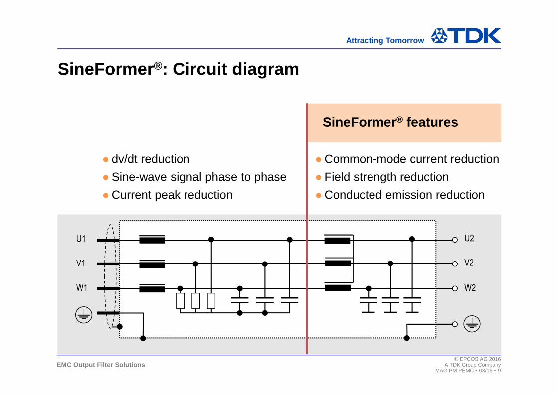
● dv/dt reduction
●Sine-wave signal phase to phase
●Current peak reduction
●Common-mode current reduction
● Field strength reduction
●Conducted emission reduction
SineFormer ® features
U1
V1
W1
U2
V2
W2
SineFormer ®: Circuit diagram

EMC Output Filter Solutions© EPCOS AG 2016
A TDK Group CompanyMAG PM PEMC • 03/16 • 10
Attracting Tomorrow
Measurements of the converter output• Phase-to-phase voltage is not
sinusoidal � Creation of interferences and bearing currents
Measurements of the filter output (300 m motor line)• Phase-to-phase voltage is sinusoidal• Asymmetric (common-mode) current
significantly reduced
SineFormer ®: Measurements /1
No shielded motor cable required, bearing currents minimized!
Phase current
Phase to phase voltage
Asymmetric current

EMC Output Filter Solutions© EPCOS AG 2016
A TDK Group CompanyMAG PM PEMC • 03/16 • 11
Attracting Tomorrow
dv/dt peaks reduced significantly to uncritical valu es
200 V M 10.0µs Ch1 4 V
C1 Pk-Pk688V
C1 Ampl688V
C1 ise3.244 µs
C1 RMS251.6 V
∆:2.0 µs@:-600 ns
dv/dt ≈ 440 V/ 2 µs ≈ 220 V/µs
Tek stop25.0 MS/s
Ch1
32 AcqsT[ ]
1�
200 V M 500ns Ch1 4 V
C1 Pk-Pk600V
C1 Ampl600V
C1 Rise179.4 ns
C1 RMS278.0 V
∆: 170 ns@: -40 ns
dv/dt ≈ 480 V/ 170 ns ≈ 2.8 kV/µs
Tek stop500 MS/s
1�
Ch1
58 AcqsT[ ]
SineFormer ®: Measurements /2
Typical value for 4 kHz switching and 50 Hz motor fre quency
Without output filter With SineFormer ®
EMC Output Filter Solutions© EPCOS AG 2016
A TDK Group CompanyMAG PM PEMC • 03/16 • 12
Attracting Tomorrow
20%
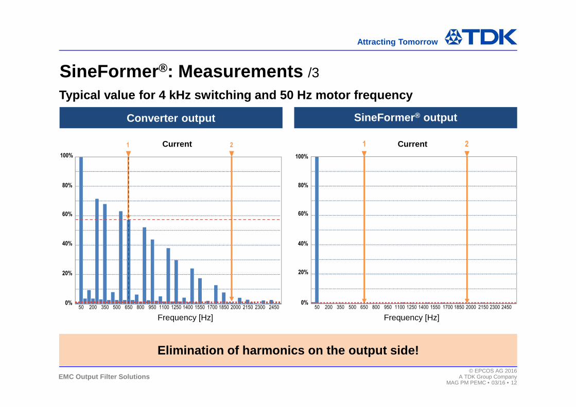
SineFormer ®: Measurements /3
Typical value for 4 kHz switching and 50 Hz motor fre quency
Converter output SineFormer ® output
Elimination of harmonics on the output side!
Frequency [Hz]50 200 350 500 650 800 950 1100 1250 1400 1550 1700 1850 2000 2150 2300 2450
0%
40%
60%
80%
100%
1 2Current
50 200 350 500 650 800 950 1100 1250 1400 1550 1700 1850 2000 2150 2300 24500%
20%
40%
60%
80%
100%
1 2Current
Frequency [Hz]

EMC Output Filter Solutions© EPCOS AG 2016
A TDK Group CompanyMAG PM PEMC • 03/16 • 13
Attracting Tomorrow
Converter and unshielded cable(without SineFormer®)
Converter and unshielded cable(with SineFormer®)
Limits exceeded
Limits kept
EN 61800-3 category C2
With output filter
Without output filter
SineFormer ®: Measurements /4
Field strength: Goodbye shielded cables!
0
10
20
30
40
50
60
70
80
30 1.000 MHz100
dBµV/m

EMC Output Filter Solutions© EPCOS AG 2016
A TDK Group CompanyMAG PM PEMC • 03/16 • 14
Attracting Tomorrow
0
10
20
30
40
50
60
70
80
Coherent results at different motor cable lengths
20 m unshieldedmotorline
150 m unshieldedmotorline
SineFormer ®: Measurements /5
Field strength performance is not dependent on cabl e length!
30 1.000 MHz100
EN 61800-3 category C2
dBµV/m

EMC Output Filter Solutions© EPCOS AG 2016
A TDK Group CompanyMAG PM PEMC • 03/16 • 15
Attracting Tomorrow
With an increase of the cable cross section, this effect will be even higher because the shielding will be more coarsely meshed.
Radiation measurement vertical antenna (worst case)●Converter 2.2 kW/ 400 V● Filter 11 A● 300 m motor cable ● 8 kHz clock frequency
30 100 1.000 MHz
Shielded motorlinewithout output filter
SineFormer® with unshielded motorline
SineFormer ®: Measurements /6
SineFormer ® + unshielded motor cable have better performance than shielded motor cables!
dBµV/m
0
10
20
30
40
50
60
70
80
EN 61800-3 category C2

EMC Output Filter Solutions© EPCOS AG 2016
A TDK Group CompanyMAG PM PEMC • 03/16 • 16
Attracting Tomorrow
Circuit
FFT: High-frequency currents provoke bearing currents
P1: max (C1)72.5 mA
����
P2: pkpk (C1)125 mA
����
Measurement bearing current with sine-wave filter●Drive 2.2 kW/ 400 V● 25 m motor line● 4 kHz clock frequency ● 5 Hz motor frequency
Bearing current measurements with sine-wave filters
Sine-wave filters only partially reduce bearing currents in the motor!
Common-mode current at the motor

EMC Output Filter Solutions© EPCOS AG 2016
A TDK Group CompanyMAG PM PEMC • 03/16 • 17
Attracting Tomorrow
Circuit
FFT: High-frequency parts
are eliminated
P1: max (C1)12.4 mA
����
P2: pkpk (C1)14 mA
����
Measurement bearing current with SineFormer ®
●Drive 2.2 kW/ 400 V● 25 m motor line● 4 kHz clock frequency ● 5 Hz motor frequency
Bearing current measurements with SineFormer ®
Only SineFormer ® filters reduce bearing currents significantly!
Common-mode current at the motor

www.SineFormer.com