EMC Europe 2016 Wrocla · EMC Europe 2016 Wroclaw ... Understanding the Physics of Electromagnetic...
117
1 UNIVERSITY OF TWENTE. TELECOMMUNICATION ENGINEERING. EMC Europe 2016 Wroclaw International Symposium and Exhibition on Electromagnetic Compatib September 5-9, 2016, Wroclaw, Poland Kees Post Lambda Engineering B.V. [email protected] Frits Buesink [email protected] EMC for LARGE Installations EMC Europe 2016, Wroclaw, Poland 2 Contents EMC for LARGE installations 1 Introduction to Electromagnetic Compatibility (EMC) Essential Requirements and Standardization 2 The physics of Electromagnetic Interference (EMI) How does it work and how to measure it? 3 Electromagnetic Phenomena Electromagnetic Environmental Effects (E 3 ) 4 Measures against interference coupling Building Electromagnetic Environments (divide & conquer) 5 Compatibility of Large Systems Organization of EMC and Reducing Complexity 6 Conclusions and recommendations The research leading to these results has received funding from the European Union on the basis of Decision No 912/2009/EC, and identified in the European Metrology Research Program (EMRP) as Joint Research Project (JRP) IND60 EMC, Improved EMC test methods in industrial environments. Additional funding was received from the EMRP participating countries UNIVERSITY OF TWENTE. TELECOMMUNICATION ENGINEERING. Lambda Engineering B.V. Acknowledgements
Transcript of EMC Europe 2016 Wrocla · EMC Europe 2016 Wroclaw ... Understanding the Physics of Electromagnetic...

1
UNIVERSITY OF TWENTE.TELECOMMUNICATION ENGINEERING.
EMC Europe 2016 Wroclaw International Symposium and Exhibition on Electromagnetic CompatibSeptember 5-9, 2016, Wroclaw, Poland
Kees PostLambda Engineering [email protected]
Frits [email protected]
EMC for LARGE Installations
EMC Europe 2016, Wroclaw, Poland 2
Contents
EMC for LARGE installations
1 Introduction to Electromagnetic Compatibility (EMC)
Essential Requirements and Standardization
2 The physics of Electromagnetic Interference (EMI)
How does it work and how to measure it?
3 Electromagnetic Phenomena
Electromagnetic Environmental Effects (E3)
4 Measures against interference coupling
Building Electromagnetic Environments (divide & conquer)
5 Compatibility of Large Systems
Organization of EMC and Reducing Complexity
6 Conclusions and recommendations
The research leading to these results has receivedfunding from the European Union on the basis ofDecision No 912/2009/EC, and identified in theEuropean Metrology Research Program (EMRP)as Joint Research Project (JRP) IND60 EMC,Improved EMC test methods in industrial environments.Additional funding was received from the EMRPparticipating countries
UNIVERSITY OF TWENTE.TELECOMMUNICATION ENGINEERING.
Lambda Engineering B.V.
Acknowledgements

2
EMC Europe 2016, Wroclaw, Poland 3
Introduction
EMC for LARGE installations
“The ability of the System to Operate according to its Specificationsin its Intended Electromagnetic Environment” [IMMUNITY]
“Without generating Unacceptable Electromagnetic Disturbancesinto that Environment” [EMISSION]
Definition of EMC
Sou
rce:
You
Tub
e
EMC Europe 2016, Wroclaw, Poland 4
Three Criteria for EMC
1. No (intolerable) emissions into the environment
2. Operate satisfactorily in its EM environment
So
urce
:Y
ouT
ube
EMC for LARGE installations
3. Not cause interference with itself3. Not cause interference with itself
3
EMC Europe 2016, Wroclaw, Poland 5
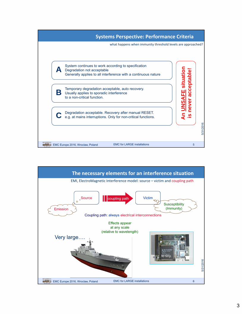
Systems Perspective: Performance Criteria
EMC for LARGE installations
what happens when immunity threshold levels are approached?
ASystem continues to work according to specificationDegradation not acceptableGenerally applies to all interference with a continuous nature
BTemporary degradation acceptable, auto recovery.Usually applies to sporadic interferenceto a non-critical function.
C Degradation acceptable. Recovery after manual RESET.e.g. at mains interruptions. Only for non-critical functions. A
n U
NS
AF
Esi
tuat
ion
is n
ever
acc
epta
ble
!
EMC Europe 2016, Wroclaw, Poland 6
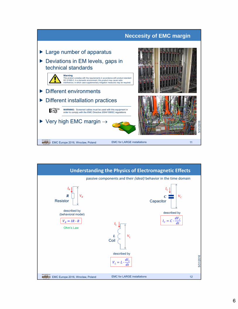
The necessary elements for an interference situation
EMI, ElectroMagnetic Interference model: source – victim and coupling path
Source Victimcoupling path
Coupling path: always electrical interconnections
to tiny.
EmissionSusceptibility
(Immunity)
Very large….
this can be demonstrated using: a noise generator a radio receiver and some cables
Effects appearat any scale
(relative to wavelength)
EMC for LARGE installations

4
EMC Europe 2016, Wroclaw, Poland 7
EMC characteristics
emission
environment
immunity
interference
I
interference
I
EMC for LARGE installations
EMC Europe 2016, Wroclaw, Poland 8
EMC characteristics of LARGE installations
SMPS, variable speed drives(frequency converters, servo drives)
Switched applications (electrical motors, pneumatics, hydraulics)
Measurement and control
Datacommunication (fieldbus, ethernet)
EM
SO
UR
CE
01011010001
EM
SU
SC
EP
TO
R
EMC?EMC for LARGE installations

5
EMC Europe 2016, Wroclaw, Poland 9
frequency
Disturbance levelvoltage (LF) field (HF)
residential
residential immunityEN-IEC 61000-6-1
residentieal emissionEN-IEC 61000-6-3
EMC margin
emission
susceptibility(immunity
industrial immunityEN-IEC 61000-6-2
industrial emissionEN-IEC 61000-6-4
industrial
Generic standards
EMC as per the requirements
EMC for LARGE installations
EMC Europe 2016, Wroclaw, Poland 10
Disturbence levelvoltage (LF) field (HF)
frequency
emission
emission limit (as per the standard)
immunity(as per the standard)
susceptibility
Lack of EMC: EMI = EM Interference
EMC for LARGE installations
6
EMC Europe 2016, Wroclaw, Poland 11
Neccesity of EMC margin
Large number of apparatus
Deviations in EM levels, gaps in technical standards
Different environments
Different installation practices
Very high EMC margin
WarningThis product complies with the requirements in accordance with product standard IEC 61800-3. In a domestic environment, this product may cause radio interference, in which case supplementary mitigation measures may be required.
WARNING: Screened cables must be used with this equipment in order to comply with the EMC Directive 2004/108/EC regulations
EMC for LARGE installations
EMC Europe 2016, Wroclaw, Poland 12
Understanding the Physics of Electromagnetic Effects
passive components and their (ideal) behavior in the time domain
RResistor
VR
IR
·
described by(behavioral model)
Ohm’s Law
LCoil
VL
IL
·
described by
CCapacitor
VC
IC
described by
·
EMC for LARGE installations

7
EMC Europe 2016, Wroclaw, Poland 13
Ideal Components do not Exist
all components have, so called, “parasitics”
EMC for LARGE installations
RResistor C
Capacitor
LCoil
EMC Europe 2016, Wroclaw, Poland 14
Any current needs a magnetic field!
field of the return conductor is identical but opposite (if geometry is identical)
EMC for LARGE installations
H = Magnetic Field [A/m] - H
Ir
rH
2
Biot Savart’s Law:
8
EMC Europe 2016, Wroclaw, Poland 15
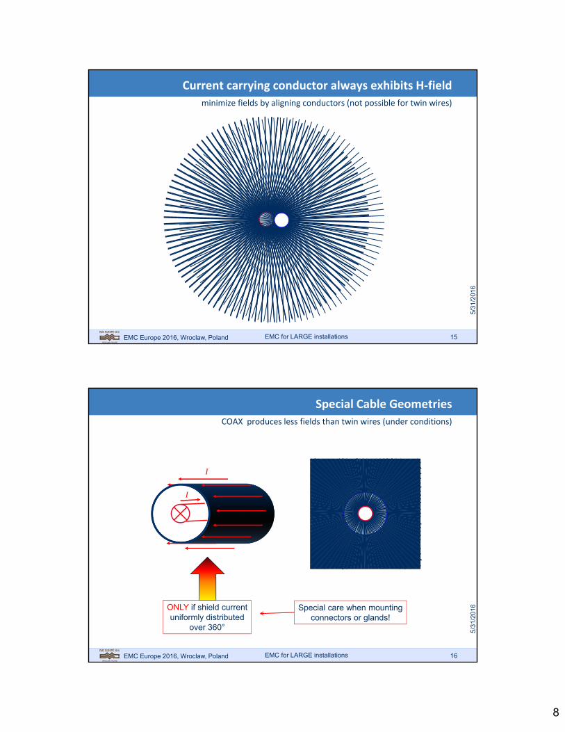
Current carrying conductor always exhibits H‐field
minimize fields by aligning conductors (not possible for twin wires)
EMC for LARGE installations
EMC Europe 2016, Wroclaw, Poland 16
Special Cable Geometries
COAX produces less fields than twin wires (under conditions)
EMC for LARGE installations
I
I
ONLY if shield currentuniformly distributed
over 360°
Special care when mountingconnectors or glands!

9
EMC Europe 2016, Wroclaw, Poland 17
Special Cable Geometries
make sure, current over shield can be uniformly distributed over 360°
EMC for LARGE installations
I
I
ONLY if shield currentuniformly distributed
over 360°
Source: Smythe W.R.“Static and Dynamic Electricity”p. 278. McGraw Hill, 1950
EMC gland with provision for 360° contact
EMC Europe 2016, Wroclaw, Poland 18
“Pig‐tails” Destroy Good Coax Properties
effect of geometry changes: fields outside interconnections; CM currents
EMC for LARGE installations
whencompared…
“Coax is betterthan
twin wires”Coax
Twinwires
Pig-tail destroys cable symmetry
Fields aregenerated

10
EMC Europe 2016, Wroclaw, Poland 19
Induction in a Single Wire
current in a conductor is only possible when a magnetic field exists
EMC for LARGE installations
50
coax cable
single wire
1. Waveform for fast edge
A B
A
B
signal integrity =no distortion onthe signal line
EMC Europe 2016, Wroclaw, Poland 20
Induction in a Single Wire
current in a conductor is only possible when magnetic field exists
EMC for LARGE installations
50
coax cable
1a. Waveform for fast edge@ reduced loop area
A B
A
B
Reduce loop area:less time and energy
needed to build H-field
single wire

11
EMC Europe 2016, Wroclaw, Poland 21
Induction in a Single Wire
current in a conductor is only possible when magnetic field exists
EMC for LARGE installations
50
coax cable
single wire
2. Waveform for slow edge
A B
A
B
EMC Europe 2016, Wroclaw, Poland 22
Simulation of Wire Inductance Demonstration
in LTSpice IV
EMC for LARGE installations

12
EMC Europe 2016, Wroclaw, Poland 23
All Currents Run in Loops
Kirchhoffs Current Law: basic for the design of component networks
EMC for LARGE installations
I1 I2
I3
Ia Ib
Kirchhoff’s electrical current law
213 III
ba II
Every current musthave a return path!
As a Designer,
ask yourself:
Where does my
Return Current
Flow?
EMC Europe 2016, Wroclaw, Poland 24
Common‐mode currents dominate the EMC arena
currents, generated by cables’ “desired currents” into CM or ground‐loop
EMC for LARGE installations
Source Load
“Ground”
“Differential-mode” currentIdm
Icm
“Common-mode” current
CM: 99%of all EMIproblems!
Common-mode current is thatpart of the return current which
follows a different path thanthe designers intended route
CM-currentscan becreated
“elsewhere”

13
EMC Europe 2016, Wroclaw, Poland 25
Demonstration of the Common Mode Current
using the three demonstration cables of slide 1
EMC for LARGE installations
50
source (50)
scope
“ground” litz wire
Any Cable
50
amplitude depends on cable quality
Current clamp
EMC Europe 2016, Wroclaw, Poland 26
“Common‐Resistance” Crosstalk
resistance in the common return path of two loops (SPICE model)
EMC for LARGE installations
source current
· 1
Isource
Inoise

14
EMC Europe 2016, Wroclaw, Poland 27
Resistive Crosstalk Waveform
linear operation: noise signal shape is identical to source waveform
EMC for LARGE installations
SourceWaveform
NoiseWaveform
EMC Europe 2016, Wroclaw, Poland 28
Kirchhoff Electrical Voltage Law
assumes all fields are inside the circuits components
EMC for LARGE installations
Kirchhoff’s Voltage Law
Us
R1
R2
UR1
UR
2
021 RRS UUU
loop 1flux flux
Faraday’s Law:
?

15
EMC Europe 2016, Wroclaw, Poland 29
Mutual induction: coupling of circuits (loops)
Field loop 1 induces voltage in loop 2 (“Crosstalk”‐ or: transformer)
EMC for LARGE installations
I1
loop 1
loop 2
MModel:
flux 1
1
212
loop
loop
IM
1
11 I
L
EMC Europe 2016, Wroclaw, Poland 30
Substitute source model for inductive crosstalk
Faraday’s Law expressed in the time and frequency domain
EMC for LARGE installations
loop 1
loop 2
flux 1
1
212
loop
loopM
1
11
L
Faraday’s Law:Faraday’s Law:
Vnoise
22
looploop
noise jdt
dV
or
112112
looploop
noise Mjdt
dMV
1122 looploop M
Vnoise
I1
Note: capacitive modelyields current source
Voltagesource

16
EMC Europe 2016, Wroclaw, Poland 31
Substitute source model for inductive probes
Faraday’s Law for a Loop Probe
Faraday’s Law:
Vloop
Vloop
Voltagesource
looploop
loop jdt
dV
or
looploop
loop AHjdt
AHdV
Loop Area, Aloop
External Magnetic Field H
HBDensityFlux r 0
looploop ABFlux
1, airr
m
H70 104
rtyPermeabiliMedium 0
EMC for LARGE installations
EMC Europe 2016, Wroclaw, Poland 32
Inductive probe for Magnetic Fields: the Model
derivation using a substitute voltage source
air gap inshielding
semi-rigid coax
chip resistor 50 (sometimes left out)
Area: A
Magnetic Field: H
instrument:50
Principle ofOperation:
MutualInduction
ABFluxCoupled HBDensityFlux
EMC for LARGE installations

17
EMC Europe 2016, Wroclaw, Poland 33
Alternative Shape: Current Clamps/Probes
current clamps use ferrite cores to guide magnetic field through coil
C-shaped Core
C-shaped Core
Both cores are clamped together aroundthe current conductor to be measured
Coil:90 turns of0.5 [mm] wire
Conductor/Current to be measuredmust be led through toroid
Coil:Fill toroid with
wire turns(Most sensitive)
MModel:
Principle ofOperation:MutualInduction
Current in Wire“to be measured”
IMFluxCoupled
EMC for LARGE installations
EMC Europe 2016, Wroclaw, Poland 34
Small Magnetic Sniffer Probe
5‐turn loop probe using ferrite to concentrate flux lines
Coil:5-6 turns of0.5 [mm] wire
Small C-shaped core
Conductor under test(or external field)
Usable for lower frequencies:• more sensitive than single loop probe• ferrite concentrates magnetic field lines
Note for Loop and Sniffer Probe
The probe output voltage is proportional to Bort
B
Hence, the MIL-STD-461 calls it a “B-dot” probe
EMC for LARGE installations

18
EMC Europe 2016, Wroclaw, Poland 35
Operation of the current probe
derivation using a substitute voltage source
R=50
Lprobe
Equivalent circuit diagram:
R=50
Measurement setup:
Vout
MjVind
probe
probeout
LR
j
LR
MjV
probeL
R
probeL
R MjVout
ML
RV
probeout
EMC for LARGE installations
EMC Europe 2016, Wroclaw, Poland 36
Operation of the current probe
graphical representation of results
probeC L
R
low frequencycut-off of probe
Calibrationlevel:
probeL
MR
Current probe: = M.Loop probe: = B.ANote
R = 50 Measure Lprobe
Calculate C
EMC for LARGE installations

19
EMC Europe 2016, Wroclaw, Poland 37
SPICE Simulation of an Inductive Probe
With LTSpice IV
EMC for LARGE installations
EMC Europe 2016, Wroclaw, Poland 38
Calibrating the Current Probe
use the following setup
coax cable
B
single wire
50 A 50
Current Probeunder test
Sine wave generator
Probe
Probe = VChannel A /50
VOutProbe = VChannel B
Make table for frequencies:
0.1, 0.2, 0.5, 1, 2, 5,10 kHz etc.
EMC for LARGE installations

20
EMC Europe 2016, Wroclaw, Poland 39
Simulate Current Probe in LTSpice
model the frequency dependent source using a transformer
The source I1 is the“current to be measured”,set as 1 Amp (no DC)
A transformer is usedto model the “frequencydependent source”Coupling Factor K1 = 1
http://www.linear.com/designtools/software/LTSpice IV (free on the Internet):
EMC for LARGE installations
EMC Europe 2016, Wroclaw, Poland 40
Examples of “home made” magnetic field probes
useful if professional equipment is unavailable
Current Clamp(separable)
magnetic field probe
Current Clamp(fixed)
EMC for LARGE installations
21
EMC Europe 2016, Wroclaw, Poland 41
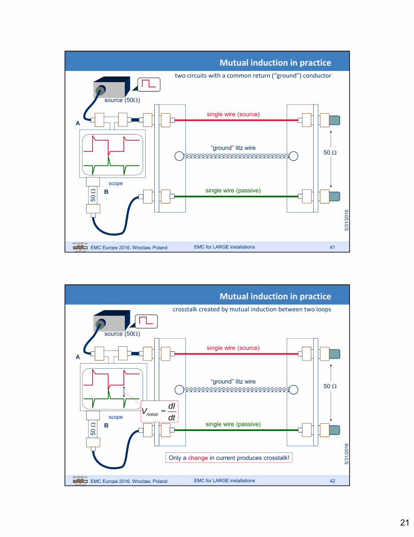
Mutual induction in practice
two circuits with a common return (“ground”) conductor
EMC for LARGE installations
source (50)
scope
“ground” litz wire
single wire (source)
single wire (passive)
50
B
50
A
EMC Europe 2016, Wroclaw, Poland 42
Mutual induction in practice
crosstalk created by mutual induction between two loops
EMC for LARGE installations
source (50)
scope
“ground” litz wire
single wire (source)
single wire (passive)
Only a change in current produces crosstalk!
50
dt
dIVnoise ~
B
50
A

22
EMC Europe 2016, Wroclaw, Poland 43
Mutual induction in practice
“common return” = common impedance, largely inductive
EMC for LARGE installations
source (50)
scope
“ground” litz wire
single wire (source)
single wire (passive)
50
B
50
A
EMC Europe 2016, Wroclaw, Poland 44
Mutual induction in practice
slower risetimes = less crosstalk
EMC for LARGE installations
source (50)
scope
“ground” litz wire
single wire (source)
single wire (passive)
Note that a slower rise timeproduces less or no crosstalk at all!
50
dt
dIVnoise ~
B
50
A

23
EMC Europe 2016, Wroclaw, Poland 45
Mutual induction in practice
thin line: two adjacent loops: high mutual inductance!
EMC for LARGE installations
source (50)
scope
“ground” litz wire
single wire (source)
single wire (passive)
50
“Mutual inductance” also knownas “Common-Impedance”
B
50
A
EMC Europe 2016, Wroclaw, Poland 46
Mutual induction in practice
solution 1: reduce loop area of source
EMC for LARGE installations
source (50)
scope
“ground” litz wire
single wire (source)
single wire (passive)
50
B
50
A

24
EMC Europe 2016, Wroclaw, Poland 47
Mutual induction in practice
solution 1a: also reduce area of victim loop
EMC for LARGE installations
source (50)
scope
“ground” litz wire
single wire (source)
single wire (passive)
50
B
50
A
EMC Europe 2016, Wroclaw, Poland 48
Ground Plane
Wide ground plane is preferredreturn path for current!
Mutual induction in practice
solution 2: wide return conductor (ground plane)
EMC for LARGE installations
source (50)
scope
single wire (source)
single wire (passive)
50
B
50
A

25
EMC Europe 2016, Wroclaw, Poland 49
Ground Plane
Mutual induction in practice
proximity effect: return current concentrates under “red” wire
EMC for LARGE installations
source (50)
scope
single wire (source)
single wire (passive)
50
Icm “squeezes”under cable
(proximityeffect)
B
50
A
Separation of “loops” becomes much easier!
victimloop
sourceloop
EMC Europe 2016, Wroclaw, Poland 50
Proximity effect
current concentrates under conductor, minimizing loop inductance
EMC for LARGE installations
Current concentrates underconductor (proximity effect)
R=50R=50
Field distribution can bemeasured with smallsniffer probe
x
J(x)

26
EMC Europe 2016, Wroclaw, Poland 51
Return Current Distribution Magnitude in Ground Plane
lowering the wire reduces volume “filled with flux”
EMC for LARGE installations
H
D
J0 or 0 JD or D
200 1
1
HDJ
J DDSource:Johnson, H“High-SpeedDigital Design”1993
EMC Europe 2016, Wroclaw, Poland 52
Wire /cable (!) distance is important
once a metal plane is used for separation
EMC for LARGE installations
H
D
Current distribution of cm in cable guide ismeasure of flux density, , coupling into
cable: at source ~L, at victim ~M!
cm
sourcesourceL
cm
victim
victim
sourceM
proximity effect
closer cable“catches” more flux
Source:Johnson, H“High-SpeedDigital Design”1993
2
1
HD
LM source
2
1
1
HDL
Mk
source
COUPLING FACTOR: k

27
EMC Europe 2016, Wroclaw, Poland 53
Wide metal also features: the Skin Effect
Lenz’Law and the basis for shielding effects
EMC for LARGE installations
CurrentSource
0 d
Edd
y cu
rren
ts
curr
en
t de
nsi
ty
0 d
J0
e
J0d
d eJJ
0
Induced Eddy currents opposedirection of external current
(Lenz’ Law)
f
1 f = frequency [Hz] = conductivity [S/m] = permeability [H/m]
EMC Europe 2016, Wroclaw, Poland 54
Any Voltage needs an Electric Field!
Two conductors in an interconnection each have an individual field pattern
EMC for LARGE installations
-+
(Electric Force lines)
28
EMC Europe 2016, Wroclaw, Poland 55
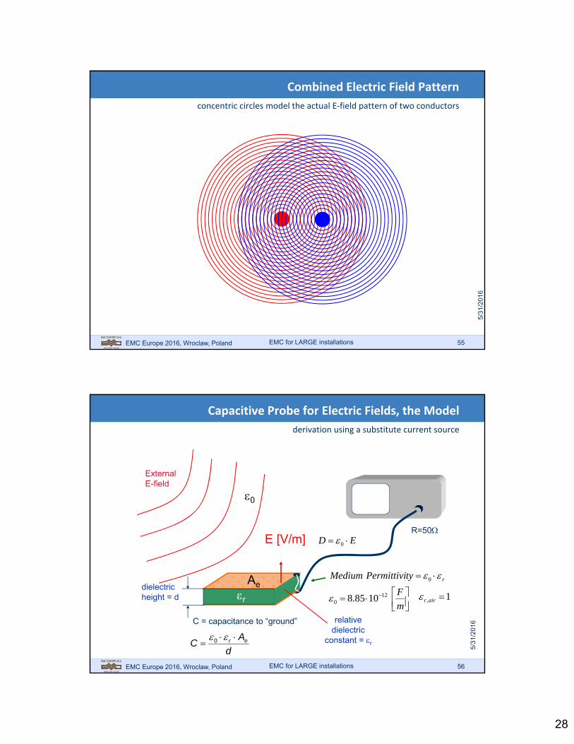
Combined Electric Field Pattern
concentric circles model the actual E‐field pattern of two conductors
EMC for LARGE installations
EMC Europe 2016, Wroclaw, Poland 56
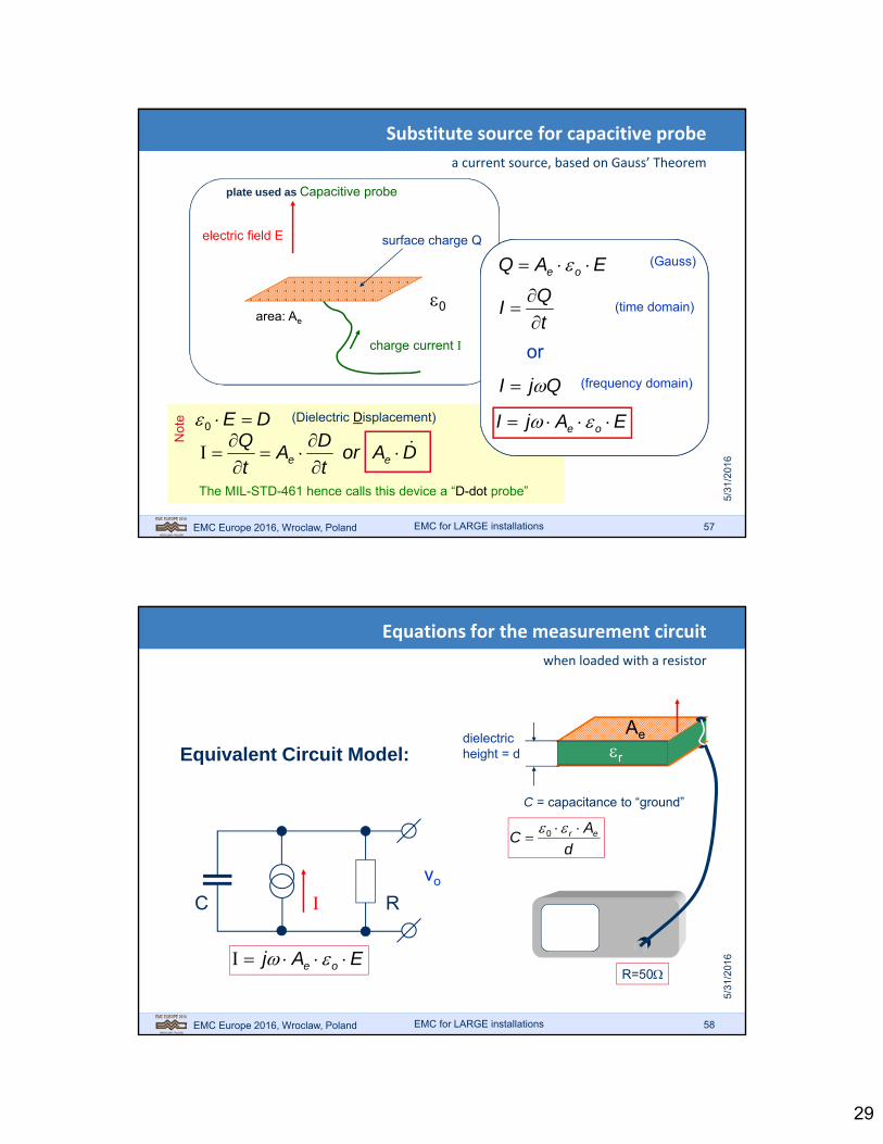
Capacitive Probe for Electric Fields, the Model
derivation using a substitute current source
dielectricheight = d
relativedielectric
constant = r
C = capacitance to “ground”
E [V/m]
ExternalE-field
R=50
d
AC er
0
r
0
AertyPermittiviMedium 0
m
F120 1085.8 1, airr
ED 0
EMC for LARGE installations
29
EMC Europe 2016, Wroclaw, Poland 57
Not
e
Substitute source for capacitive probe
a current source, based on Gauss’ Theorem
electric field E
charge current I
plate used as Capacitive probe
surface charge Q
or
EAjI oe
t
QI
(time domain)
QjI (frequency domain)
EAQ oe (Gauss)
area: Ae
0
DE 0 (Dielectric Displacement)
DAort
DA
t
Qee
The MIL-STD-461 hence calls this device a “D-dot probe”
EMC for LARGE installations
EMC Europe 2016, Wroclaw, Poland 58
Equations for the measurement circuit
when loaded with a resistor
EAj oe
C RI
vo
d
AC er
0
dielectricheight = d
C = capacitance to “ground”
r
Ae
R=50
Equivalent Circuit Model:
EMC for LARGE installations
30
EMC Europe 2016, Wroclaw, Poland 59
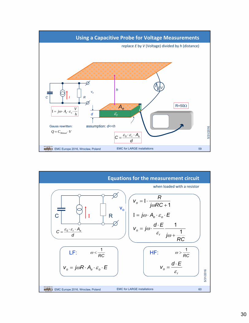
Using a Capacitive Probe for Voltage Measurements
replace E by V (Voltage) divided by h (distance)
d r
Ae
h
R=50
V
assumption: d<<h
h
VAj oe
d
AC er
0
C RI
vo
VCQ Mutual Gauss rewritten:
EMC for LARGE installations
EMC Europe 2016, Wroclaw, Poland 60
Equations for the measurement circuit
when loaded with a resistor
1
RCj
Rvo
EAj oe
RCj
Edjv
ro 1
1
LF:
EARjv oeo
RC
1 HF:
ro
Edv
RC
1
C RI
vo
d
AC er
0
EMC for LARGE installations
31
EMC Europe 2016, Wroclaw, Poland 61
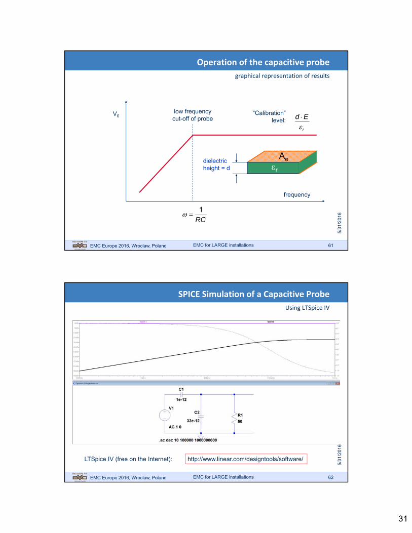
Operation of the capacitive probe
graphical representation of results
RC
1
low frequencycut-off of probe
“Calibration”level:
r
Ed
frequency
V0
dielectricheight = d r
Ae
EMC for LARGE installations
EMC Europe 2016, Wroclaw, Poland 62
SPICE Simulation of a Capacitive Probe
Using LTSpice IV
http://www.linear.com/designtools/software/LTSpice IV (free on the Internet):
EMC for LARGE installations

32
EMC Europe 2016, Wroclaw, Poland 63
Commercial Capacitive Clamp
Example of some electric field probes
useful if professional equipment is unavailable
Insulate!
Can sense E-fieldsand generate them!
Rod type probe
EMC for LARGE installations
EMC Europe 2016, Wroclaw, Poland 64
Combination of capacitive and inductive crosstalk
depending on load of source line, capacitive or inductive effects dominate
EMC for LARGE installations
50 instrumentor termination
50 instrumentor termination
50 instrumentor termination
82
8
2
82
12
0
Terminationselect switch
H
E
Z0
3204
sizes in mm, line impedances 130
50
10
20
receiving line
source line
Aluminiumgroundplane
Construction details
Brassconductors
Electrical Diagram
active line
passive line
(Source)
(Load)
Source: J.J. Goedbloed “EMC”, Kluwer 1993

33
EMC Europe 2016, Wroclaw, Poland 65
Flow of currents determines crosstalk behaviour
always look for the current paths, inductive and capacitive
EMC for LARGE installations
MutualInduction
gene
rato
r
A B
Scope
Capacitive situation
C
cap
Crosstalk “in phase”
gene
rato
r
Inductive situation
ind
Crosstalk “in anti-phase”
react
A B
Scope
Open end Shorted end
EMC Europe 2016, Wroclaw, Poland 66
Balancing capacitive and inductive crosstalk
terminating the source line with its characteristic impedance
EMC for LARGE installations
MutualInduction
Z0 terminated situation
ind
Crosstalk far end “balanced”
react
terminatewith Z0
gene
rato
r C
cap
A B
Scope
12
0

34
EMC Europe 2016, Wroclaw, Poland 67
Capacitive or Inductive Sniffer Probe shows Field
magnetic field (shorted source line) or electric field (open source line)
EMC for LARGE installations
Use probe near source line
NoteTerminated Line:Both Field Types
“D-dot” (E-) probe
“B-dot”(H-) probe
EMC Europe 2016, Wroclaw, Poland 68
Crosstalk between two circuits (loops)
interference between line 1 and 2; mutual induction, substitute source model
1
M12
1
2
1122 MjV
EMC for LARGE installations
35
EMC Europe 2016, Wroclaw, Poland 69
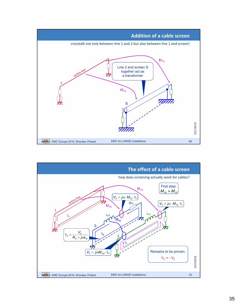
Addition of a cable screen
crosstalk not only between line 1 and 2 but also between line 1 and screen!
S
1
2
Line 2 and screen Stogether act asa transformer
M12
M1S
EMC for LARGE installations
EMC Europe 2016, Wroclaw, Poland 70
The effect of a cable screen
how does screening actually work for cables?
M12
1
1
2
S
MS2
M1S
2
C
11 SS MjV
1122 MjV
SS
SS LjR
V
SSC MjV 2 Remains to be proven:
VC = - V2
First step:
121 MM S
112 MjVS
S
EMC for LARGE installations

36
EMC Europe 2016, Wroclaw, Poland 71
Inside metal tube there is no field
if current is distributed evenly over 360° circumference of this tube
Evenly distributedcurrent density over360° circumference S
H
H
s S
SSL
S
SSM
2
if all flux is “outside”
hence,
SS LM 2
Source: Smythe W.R.“Static and Dynamic Electricity”p. 278. McGraw Hill, 1950
S2No fluxinside tube!
Presence of innerconductor: no change!
EMC for LARGE installations
EMC Europe 2016, Wroclaw, Poland 72
To find the remaining noise voltage after screening
fill out the equation for (V2 – VC)
2
S
MS2
2
C
1122 MjV
SS
SS LjR
V
SSC MjV 2
112 MjVS
S
SSC LjV
MS2 = LS
Remaining noise voltageon line 2 (fill out equations):
SSC LjMjVV 1122
and replace S:
SSSC LjR
IMjLjIMjVV
112
1122
)1(1122
S
SC
LR
j
jIMjVV
original crosstalk
without screening!
Improvement
EMC for LARGE installations

37
EMC Europe 2016, Wroclaw, Poland 73
Graphic representation of screening effect
in relation to the crosstalk in the unscreened situation
frequency
nois
e v
olta
ge o
n lin
e 2
with (ideal) screen
S
SSC L
R (screen cut-off frequency)
Message:Audio (lowfrequency)screeningis difficult!
Improvement
EMC for LARGE installations
EMC Europe 2016, Wroclaw, Poland 74
20 [dB] Attenuation Trace
-70
-60
-50
-40
-30
-20
-10
0
1.00E+06 2.01E+08 4.01E+08 6.01E+08 8.01E+08 1.00E+09 1.20E+09
linear frequency scale
Crosstalk at higher frequencies
transmission line effects when wire or cable length reaches \4
EMC for LARGE installations
frequency
nois
e v
olta
ge o
n lin
e 2
Crosstalk does not increasewith frequency forever!
Wire
-leng
th =
/4
asymptote20 [dB] Attenuation Trace
-70
-60
-50
-40
-30
-20
-10
0
1.00E+06 1.00E+07 1.00E+08 1.00E+09
logarithmic frequency scale

38
EMC Europe 2016, Wroclaw, Poland 75
The Common‐mode Coil
appearances: from factory installed to self made
Common-modecoils
Clip-onversion
open
closed
UTP cablewound onferrite ring
factoryinstalled
EMC for LARGE installations
EMC Europe 2016, Wroclaw, Poland 76
Loop-area responsible for Ls and Ms2
The Common‐mode Coil
improve, essentially, the low frequency behaviour of a cable
ferrite tubeon cable
ferrite increases LS (RS unaffected)
cable (shielded)2
S
Vn
ois
e
frequency
S
SSC L
R
S
SSC L
R
''
LS increased
EMC for LARGE installations

39
EMC Europe 2016, Wroclaw, Poland 77
The Common‐mode Coil
drawback: does not work at very high frequencies (fields travel around it)
Input and output“see” each other
(for high frequencies)
C
EMC for LARGE installations
EMC Europe 2016, Wroclaw, Poland 78
Incomplete screening
What if the screen does not completely cover the inner wire?
EMC for LARGE installations
Ideal Screening
WorkableCompromise(Pig-Tail)
2
S
MS2
2
C
S
MS2 = LS
MS2 LS
e.g. MS2 = 0.95⋅LS

40
EMC Europe 2016, Wroclaw, Poland 79
Incomplete screening
in relation to the crosstalk in the complete‐ and un‐screened situation
frequency
nois
e v
olta
ge o
n lin
e 2
with (ideal) screen
S
SSC L
R
Improvement
EMC for LARGE installations
S
SHF L
R
95.01
1
Loss
EMC Europe 2016, Wroclaw, Poland 80
Pig-Tail for EMCDemonstrations
Pig‐Tails
to some extent, pig‐tails are unavoidable
EMC for LARGE installations
Commercially Available Pig-Tail

41
EMC Europe 2016, Wroclaw, Poland 81
Lunch Break
EMC for LARGE installations
EMC Europe 2016, Wroclaw, Poland 82
Measures to Improve Low Frequency Performance
balancing measures e.g. using Unshielded Twisted Pairs (UTP)
Balanced Driver
1
2a
2b
M12
Two identicalsubstitute sourcesare introduced
EMC for LARGE installations
Balanced Receivercommon mode noise
is cancelled!
42
EMC Europe 2016, Wroclaw, Poland 83
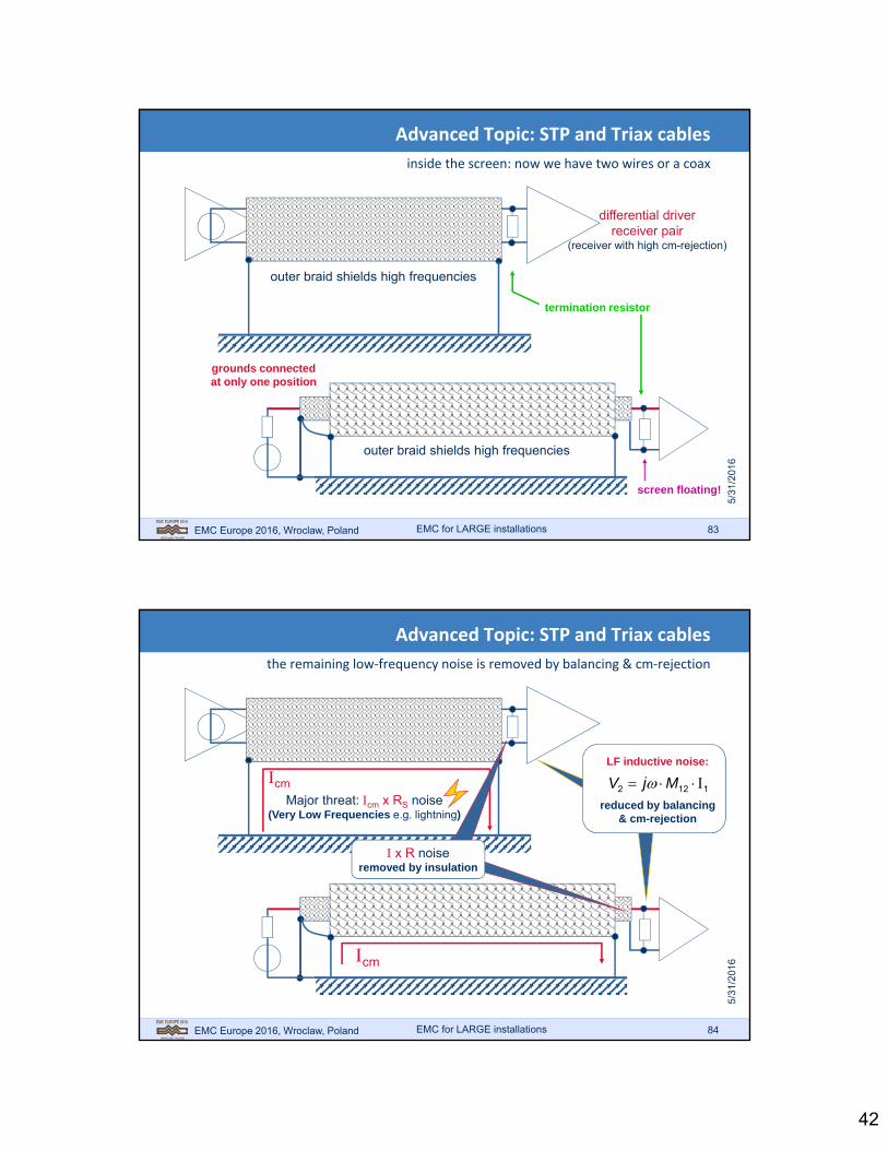
Advanced Topic: STP and Triax cables
inside the screen: now we have two wires or a coax
outer braid shields high frequencies
differential driverreceiver pair
(receiver with high cm-rejection)
grounds connectedat only one position
termination resistor
screen floating!
outer braid shields high frequencies
EMC for LARGE installations
EMC Europe 2016, Wroclaw, Poland 84
cm
Advanced Topic: STP and Triax cables
the remaining low‐frequency noise is removed by balancing & cm‐rejection
Major threat: cm x RS noise(Very Low Frequencies e.g. lightning)
cm
1122 MjV LF inductive noise:
reduced by balancing& cm-rejection
EMC for LARGE installations
x R noiseremoved by insulation

43
EMC Europe 2016, Wroclaw, Poland 85
Properties of cables: Transfer Impedance ZTcable may produce or pick up common mode currents
EMC for LARGE installations
external noise source
Inoise
Unoise
1. Coupling into external noise
cable length D
Idesired
return current flows where?
?
2. Generation of noise in other conductors(e.g. “ground”)
DI
UZ
noise
noiseT
[Ohm per meter]
EMC Europe 2016, Wroclaw, Poland 86
Signal and Return Circuit have Mutual Induction
COAX example: screen and centre wire form a transformer
EMC for LARGE installations
Cable
Loop 1 (Signal loop / induction)
Loop S (Return loop / induction)
1S
L1
LS
MS1
44
EMC Europe 2016, Wroclaw, Poland 87
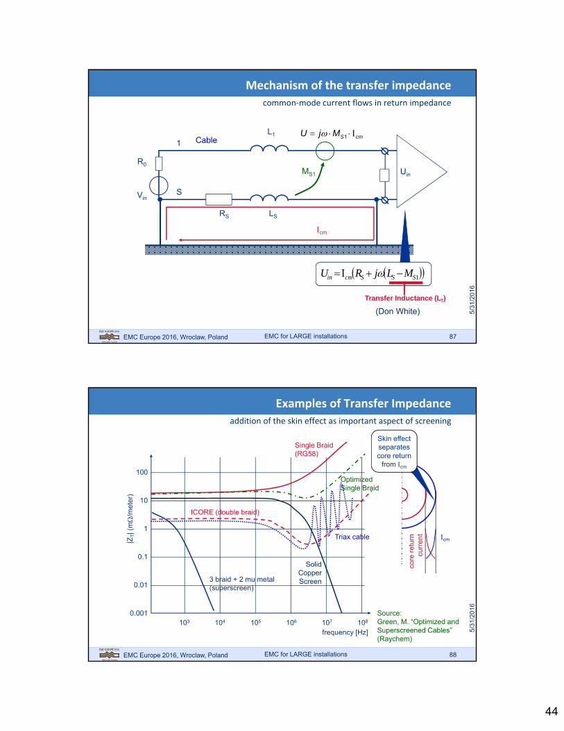
Mechanism of the transfer impedance
common‐mode current flows in return impedance
EMC for LARGE installations
RS LS
L1
R0
Uin
Cable
Vin
MS1
cmSMjU 1
Scmin LjRU 1SSScmin MLjRU
Transfer Inductance (LT)
1
S
(Don White)
cm
EMC Europe 2016, Wroclaw, Poland 88
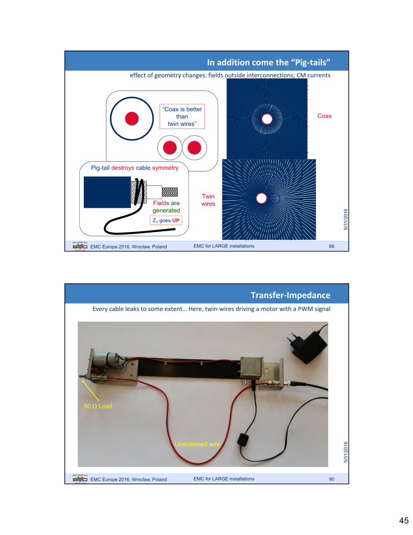
Examples of Transfer Impedance
addition of the skin effect as important aspect of screening
EMC for LARGE installations
103 104 105 106 107 108
frequency [Hz]
100
10
1
0.1
0.01
0.001
|ZT| (
m
/met
er)
3 braid + 2 mu metal(superscreen)
SolidCopperScreen
Single Braid(RG58)
Source:Green, M. “Optimized andSuperscreened Cables”(Raychem)
core
ret
urn
curr
ent cmTriax cable
ICORE (double braid)
OptimizedSingle Braid
Skin effectseparatescore return
from cm
45
EMC Europe 2016, Wroclaw, Poland 89
In addition come the “Pig‐tails”
effect of geometry changes: fields outside interconnections; CM currents
EMC for LARGE installations
whencompared…
“Coax is betterthan
twin wires”Coax
Twinwires
Pig-tail destroys cable symmetry
Fields aregenerated
ZT goes UP
EMC Europe 2016, Wroclaw, Poland 90
Transfer‐Impedance
Every cable leaks to some extent… Here, twin‐wires driving a motor with a PWM signal
EMC for LARGE installations
Plaatje motor demo zonder kabelgoot
50 Load
Unscreened wire

46
EMC Europe 2016, Wroclaw, Poland 91
Transfer impedance of PWM driven DC motor
Switching moments visible as 2 Vpp transients
EMC for LARGE installations
EMC Europe 2016, Wroclaw, Poland 92
Transfer Impedance Crosstalk in practice
looks remarkably similar to inductive crosstalk between wires!
EMC for LARGE installations
source (50)
scope
Cable 1 (source)
Cable 2 (passive)
50
B
50
A
(ZT cable 1)
(ZT cable 2)
I CM
(=
no
ise
)

47
EMC Europe 2016, Wroclaw, Poland 93
EMC demo installation
► EM sources: variable speed drive, circuit breaker, RF transmitter
► EM victims (analog measurement/control, protection relay)
► Coupling paths
► Cable shielding
EMC for LARGE installations
EMC Europe 2016, Wroclaw, Poland 94
Complies with EMC Directive 2004/108/EC
Immunity to interference in acc. with EN 61000-6-2
Noise emission in acc. with EN 61000-6-4
EMC specification + installation requirement
EMC for LARGE installations

48
EMC Europe 2016, Wroclaw, Poland 95
Power electronics (variable speed drives/VSD, thyristor controllers, softstarters, UPS, HF lighting)
Switched devices (relays, circuit breakers, contactors, vacuum/GIS, pneumatic- and hydraulicvalves/solenoids)
Lightning and induction effects
HF transmitters (portable transmitters, mobile telephones, fixed transmitters for communication en navigation)
ESD (moving materials, machines with non-conductive elements, conveyor belt, oil tanks, etc.)
Frequently experienced EM sources
EMC for LARGE installations
EMC Europe 2016, Wroclaw, Poland 96
Continuous and transient sources
Continuous
► VSD
► Servo drive
► UPS
► Switched mode power supply(SMPS)
Transient
► Relay, circuit breaker/ contactor
► Valve (solenoid)
► ESD
► Lightning, short circuit
EMC for LARGE installations

49
EMC Europe 2016, Wroclaw, Poland 97
UPS = Uninterruptible Power Supply VSD = Variable Speed DriveFC = Frequency Converter
line inductor
input filter
output filter
rectifier inverter
Power electronics (UPS and VSD)
EMC for LARGE installations
EMC Europe 2016, Wroclaw, Poland 98
Low Frequency (LF)• harmonic currents• notches (from thyristors)
ILF
High Frequency (HF) transientcurrents and voltages from inverter(harmonics of inverterfrequency)
IHF
IHF
Rectifier direct (diodes) or
regulated (thyristors)
InverterIGBT’s/ fast transistors
for high efficiencyDC bus
Power distribution
system Load
Electrical motor/servo motor
M
VSD/servo drive
Variable Speed Drive
EMC for LARGE installations

50
EMC Europe 2016, Wroclaw, Poland 99
= PREFERRED CURRENT
RETURN PATH
CFD CDC
► Capacitance of motor winding(s) and motor cables causes capacitive current due to high dV/dt: I = (CM+CC).dV/dt
► Output filter required to mitigate dV/dt
► Motor cable shield provides preferred return current path
► Internal return path capacitors required in VSD (in DC bus and/or in power supply filter)
OPTIONAL
INPUT FILTER
CFO
CM
CC
CC
dV/dt
ICM
MOTOR
CM
MOTOR CABLE
VARIABLE SPEED DRIVE
TRANSFORMER
PLANT EARTH GRID
VSD EARTH BAR
Basic EMC concepts of VSD
EMC for LARGE installations
EMC Europe 2016, Wroclaw, Poland 100
Typical IGBT switching rate: 5kV/s (high efficiency)Example: finv = 4kHz T=250s
th = 50s 1/ th = 6.4kHztr = 100ns 1/ tr = 3.2MHz
U(t) log(U)
U(f)
Frequency spectrum of VSD emissions
TIME DOMAIN FREQUENCY DOMAIN
with
FOURIER
EMC for LARGE installations
51
EMC Europe 2016, Wroclaw, Poland 101
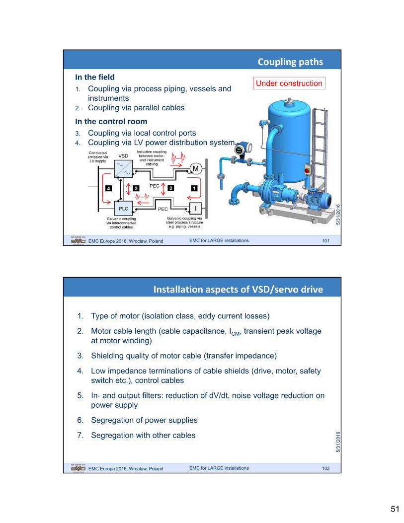
In the field
1. Coupling via process piping, vessels and instruments
2. Coupling via parallel cables
In the control room
3. Coupling via local control ports4. Coupling via LV power distribution system
Under construction
Coupling paths
EMC for LARGE installations
EMC Europe 2016, Wroclaw, Poland 102
1. Type of motor (isolation class, eddy current losses)
2. Motor cable length (cable capacitance, ICM, transient peak voltage at motor winding)
3. Shielding quality of motor cable (transfer impedance)
4. Low impedance terminations of cable shields (drive, motor, safety switch etc.), control cables
5. In- and output filters: reduction of dV/dt, noise voltage reduction on power supply
6. Segregation of power supplies
7. Segregation with other cables
Installation aspects of VSD/servo drive
EMC for LARGE installations
52
EMC Europe 2016, Wroclaw, Poland 103
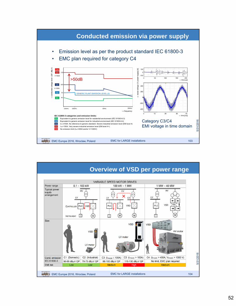
frequency
150kHz 500kHz 5MHz 30MHz
66
79
130
c
ondu
cted v
olta
ge le
vel
(QP
, dBV
)
100
C1
C2
C3
C3
I>100A
I100A
IEC 61800-3 categories and emission limits: C1 Equivalent to generic emission level for residential environment (IEC 61000-6-3)
C2 Equivalent to generic emission level for industrial environment (IEC 61000-6-4)
C3 IPH ≤100A. No reference to generic standard. Severe industrial emission level (EM level 4)
C3 IPH>100A. Very severe industrial emission level (EM level 4+)
C4 No emission limit (IPH>400A and/or V>1000V)
C4
GENERIC PLANT EMISSION LEVEL (3)
• Emission level as per the product standard IEC 61800-3
• EMC plan required for category C4
Category C3/C4 EMI voltage in time domain
>50dB
Conducted emission via power supply
EMC for LARGE installations
EMC Europe 2016, Wroclaw, Poland 104
Overview of VSD per power range
EMC for LARGE installations

53
EMC Europe 2016, Wroclaw, Poland 105
The Three Dimensions of EMC
systems EMC requirements are set by the environment it is intended for
Ground BasedAirborneAt Sea
Industry
Domestic
Small
MediumLarge
[Tests to cover]
EMC for LARGE installations
EMC Europe 2016, Wroclaw, Poland 106
Standards address different EM Phenomena
tests are defined to check each relevant aspect
EMC for LARGE installations
54
EMC Europe 2016, Wroclaw, Poland 107
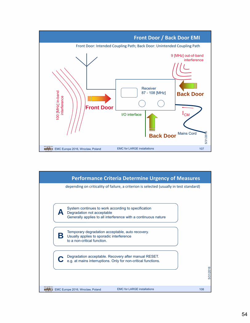
Front Door / Back Door EMI
Front Door: Intended Coupling Path; Back Door: Unintended Coupling Path
Receiver87 - 108 [MHz]
Mains Cord
100
[MH
z] in
-ban
din
terf
eren
ce
Front DoorCM
9 [MHz] out-of-bandinterference
Back Door
Back Door
I/O interface
EMC for LARGE installations
EMC Europe 2016, Wroclaw, Poland 108
Performance Criteria Determine Urgency of Measures
depending on criticality of failure, a criterion is selected (usually in test standard)
ASystem continues to work according to specificationDegradation not acceptableGenerally applies to all interference with a continuous nature
BTemporary degradation acceptable, auto recovery.Usually applies to sporadic interferenceto a non-critical function.
C Degradation acceptable. Recovery after manual RESET.e.g. at mains interruptions. Only for non-critical functions.
EMC for LARGE installations
55
EMC Europe 2016, Wroclaw, Poland 109
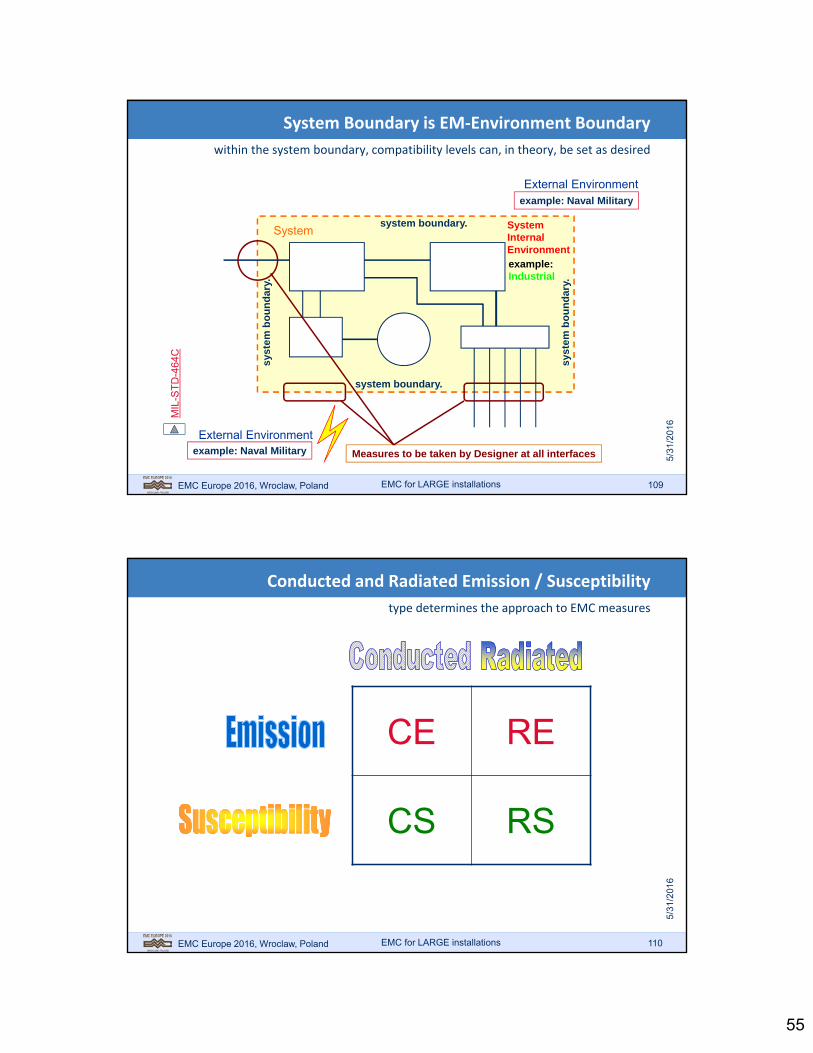
Measures to be taken by Designer at all interfaces
SystemInternalEnvironment
System Boundary is EM‐Environment Boundary
within the system boundary, compatibility levels can, in theory, be set as desired
System
External Environment
External Environment
system boundary.
syst
em b
ou
nd
ary.
syst
em b
ou
nd
ary.
system boundary.
example: Naval Military
example: Naval Military
example:Industrial
MIL
-ST
D-4
64C
EMC for LARGE installations
EMC Europe 2016, Wroclaw, Poland 110
Conducted and Radiated Emission / Susceptibility
type determines the approach to EMC measures
CE RE
CS RS
EMC for LARGE installations

56
EMC Europe 2016, Wroclaw, Poland 111
(Continuous) Immunity Aspects
“interference” from “others” through EM‐fields
Intentional Emitters
EMC for LARGE installations
EMC Europe 2016, Wroclaw, Poland 112
(Continuous) Immunity Aspects
from “elsewhere” through cabling (conducted interference)
FrequencyController
FrequencyControlled
Motor
Motor Cable
dttVtP )()(
Voltage Current
“MinimizeDissipationwith Fast V/Transitions”
EMC for LARGE installations

57
EMC Europe 2016, Wroclaw, Poland 113
In High Field Environments Equipment May Fail
booster transmitters and antennas are often installed for communication
Search party for the hidden source
Car remote controls were disturbed…
EMC for LARGE installations
EMC Europe 2016, Wroclaw, Poland 114
Non‐linear Effects
out of band interference
Voltage
Cur
rent
DC offset
frequency
ampl
itude
100 MHz
0 Hz
Prevent HF signals fromreaching semiconductors
Do not amplify HF signalsthat did get in
EMC for LARGE installations

58
EMC Europe 2016, Wroclaw, Poland 115
Non‐Linearity Disaster Pictures
EMC for LARGE installations
EMC Europe 2016, Wroclaw, Poland 116
ElectroStatic Discharge
charges built on persons or equipment cause electric sparks (and currents)
Sou
rce:
You
Tub
e
EMC for LARGE installations

59
EMC Europe 2016, Wroclaw, Poland 117
Electric charging by induction
direct contact not necessary!
Teflon
Wool
Printed Circuit Board
- - - - - - - - - - - - - - - - -+ + + + + + + + + + + + + + + +
1. Charging of an insulator
2. Insulated PCB on charged surface
- - - - - - - - - - - - - - - - - - - -
- - - - - - - - - - - - - - - - -Source:IEEE EMC Education ManualPage 13-15: “ESD”Tony NasutaWestinghouse Electric Corp.
EMC for LARGE installations
EMC Europe 2016, Wroclaw, Poland 118
Electric charging by induction
direct contact not necessary!
+ + + + + + + + + + + + + + + +
3.Touch or Ground PCB:
negative charge disappears (spark)(PCB possibly damaged)
4. Lift PCB: voltage increases! Sparks fly!
- - - - - - - - - - - - - - - - -
- - - - - - - - - - - - - - - - -
- - - - - - - - - - - - - - - - -
+ + + + + + + + + + + + + + + +
PCB
PCBPCB C
QV (CPCB decreases)
EMC for LARGE installations
60
EMC Europe 2016, Wroclaw, Poland 119
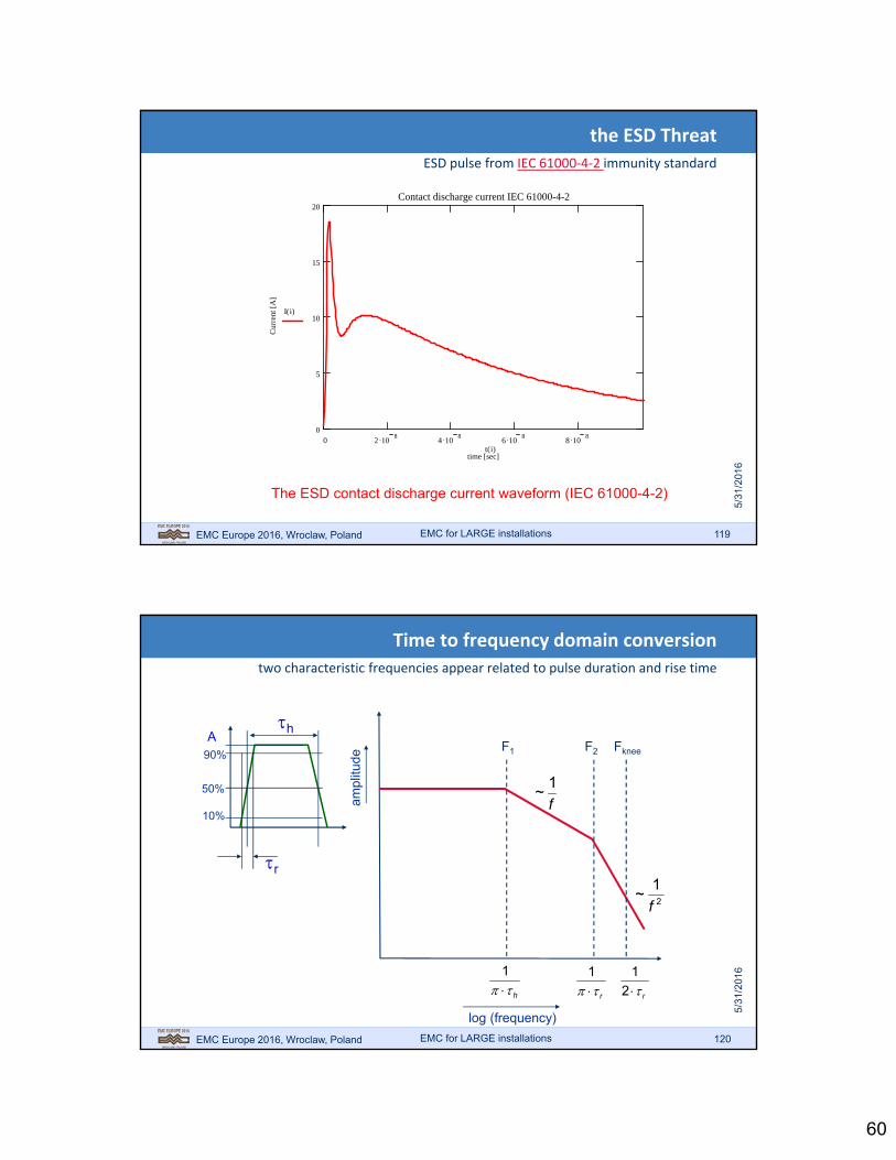
the ESD Threat
ESD pulse from IEC 61000‐4‐2 immunity standard
0 2 108
4 108
6 108
8 108
0
5
10
15
20Contact discharge current IEC 61000-4-2
time [sec]
Cur
rent
[A
]
I i( )
t i( )
The ESD contact discharge current waveform (IEC 61000-4-2)
EMC for LARGE installations
EMC Europe 2016, Wroclaw, Poland 120
Time to frequency domain conversion
two characteristic frequencies appear related to pulse duration and rise time
A
50%
90%
10%
h
r
Fknee
h 1
r 1
r2
1
F1 F2
ampl
itude
log (frequency)
f
1~
2
1~
f
EMC for LARGE installations

61
EMC Europe 2016, Wroclaw, Poland 121
ESD pulse can be decomposed into two trapezoids
this allows an estimate of the ESD current frequency spectrum
0 2 108
4 108
6 108
8 108
0
5
10
15
20Building blocks contact discharge pulse
time [s]
curr
ent [
A]
IS i( )
IF i( )
I i( )
t i( )
Short and long pulse added in the time domain
Fast pulse: r=0.7 ns; h=10 ns
Slow pulse: r=10 ns; h=60 ns
To convert the ESD pulseto frequencies, it can besplit into two trapezoids
EMC for LARGE installations
EMC Europe 2016, Wroclaw, Poland 122
Spectra of slow and fast pulse can be added
the resulting spectrum is used for shielding analyses
1 106
1 107
1 108
1 109
1 1010
1 1010
1 109
1 108
1 107
1 106
1 105
ESD current spectrum
frequency
curr
ent c
ontr
ibut
ion Iesd i( )
IesdS i( )
IesdF i( )
f i( )
Total current
Sum
Fast pulse
Slow pulse
EMC for LARGE installations

62
EMC Europe 2016, Wroclaw, Poland 123
Inductive load switching
Relays, Valves, and PWM motor control systems
V0
SW
L
C(parasitic)
R(parasitic)
Basic model
0
2
2
1 LEnergy
par
2
2
1VCEnergy
22
2
1
2
1VCL
L= 0.1 HC= 100 pF = 1 A
V = 32 kV (!)
Analysis:
Source: Jasper J. Goedbloed, “EMC”Prentice Hall/Kluwer 1992
EMC for LARGE installations
EMC Europe 2016, Wroclaw, Poland 124
High Voltage in Switch Arcs and Creates Spikes
reason for Electrical Fast Transients (EFT) tests on equipment
ampl
itude
time (s scale)
breakdown (ns scale)
from EN 61000-4-4
5/50 ns pulses
EMC for LARGE installations
63
EMC Europe 2016, Wroclaw, Poland 125
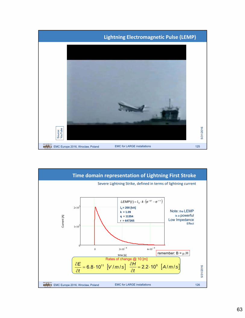
Lightning Electromagnetic Pulse (LEMP)
Sou
rce:
You
Tub
e
EMC for LARGE installations
EMC Europe 2016, Wroclaw, Poland 126
Time domain representation of Lightning First Stroke
Severe Lightning Strike, defined in terms of lightning current
EMC for LARGE installations
0 2 104 4 10
40
1 105
2 105
time [s]
Cur
rent
[A
]
trtq eektLEMP 0)(
0 = 200 [kA]
k = 1.09
q = 11354
r = 647265
Note: the LEMPis a powerful
Low ImpedanceEffect
Rates of change @ 10 [m]
smVt
E//108.6 11
smA
t
H//102.2 9
remember: B = .H

64
EMC Europe 2016, Wroclaw, Poland 127
Frequency Domain graph of Lightning First Stroke
it is clear that most of the lightning energy is in the low frequency area
1 100 1 104 1 10
6 1 108 1 10
100
5
10
15
20
frequency [Hz]
[A/H
z]
EMC for LARGE installations
EMC Europe 2016, Wroclaw, Poland 128
Calculate the Effect of an Indirect Lightning Stroke
using Faraday’s Law
Lig
htn
ing
Cu
rren
t
=
=
2·101
0A/s
=2.2· 109
[A/m/s] @ 10 [m]
H
R=distance to stroke
2
surface: A [m2]
Flux in Loop: ·
Induced Voltage:
·where
V
time domain:
frequency domain:
· ·
I, B or is multiplied by frequency!
EMC for LARGE installations

65
EMC Europe 2016, Wroclaw, Poland 129
Normalized Frequency Domain Graph of Lightning
shows frequencies of maximum impact (voltage induced in small loop)
1 100 1 104 1 10
6 1 108 1 10
10100
50
0
50
Frequency [Hz]
Indu
ced
volta
ge [d
BuV
/Hz]
multiply every amplitude in the graph by its frequency: “Normalization”
EMC for LARGE installations
EMC Europe 2016, Wroclaw, Poland 130
Distribution of Lightning over the World and the Year
NASA movie clip
Sou
rce:
You
Tub
e
EMC for LARGE installations

66
EMC Europe 2016, Wroclaw, Poland 131
High Altitude Nuclear Explosion Initiates E‐field Pulse
The Compton Effect converts Gamma Ray Energy into Electric Field
The Compton Effect
EMC for LARGE installations
EMC Europe 2016, Wroclaw, Poland 132
Extra‐Atmospheric Nuclear EMP Blast is Far‐Field
in the far field there is a fixed ratio of Electric and Magnetic Field (Impedance)
= 120· 377Ω 0
Impedance of Vacuum or Air
• This means that if you know one (E or H)
• You can calculate the other!
• EMP is usually specified in terms of E (!)
• If you need H, calculate it.
EMC for LARGE installations

67
EMC Europe 2016, Wroclaw, Poland 133
HEMP Impulse Illuminates Large Areas
Ground Coverage for High‐Altitude Bursts at 100, 300 and 500 km
EMC for LARGE installations
EMC Europe 2016, Wroclaw, Poland 134
The HEMP Phenomenon (movie clip)
Sou
rce
:Y
ouT
ube
Fut
ure
wea
pons
: E
MP
bom
b
EMC for LARGE installations
68
EMC Europe 2016, Wroclaw, Poland 135
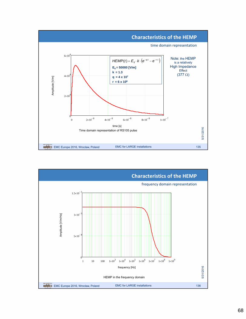
Characteristics of the HEMP
time domain representation
0 2 108 4 10
8 6 108 8 10
8 1 107
0
2 104
4 104
6 104
time [s]
Am
plitu
de [
V/m
]
Time domain representation of RS105 pulse
trtq eekEtHEMP 0)(
E0 = 50000 [V/m]
k = 1.3
q = 4 x 10⁷
r = 6 x 10⁸
Note: the HEMPis a relatively
High ImpedanceEffect
(377 )
EMC for LARGE installations
EMC Europe 2016, Wroclaw, Poland 136
Characteristics of the HEMP
frequency domain representation
1 10 100 1 103 1 10
4 1 105 1 10
6 1 107 1 10
8 1 109
0
5 104
1 103
1.5 103
frequency [Hz]
Am
plitu
de [
V/m
/Hz]
HEMP in the frequency domain
EMC for LARGE installations

69
EMC Europe 2016, Wroclaw, Poland 137
Normalizing to find Frequency of Maximum Impact
effective induced voltage in a small loop as function of frequency
1 100 1 104 1 10
6 1 108 1 10
10100
50
0
50
Frequency [Hz]
Indu
ced
volta
ge [
dBuV
/Hz]
Induced voltage spectrum for HEMP
EMC for LARGE installations
EMC Europe 2016, Wroclaw, Poland 138
Estimation of the Effects
Sou
rce:
You
Tub
e
EMC for LARGE installations
70
EMC Europe 2016, Wroclaw, Poland 139
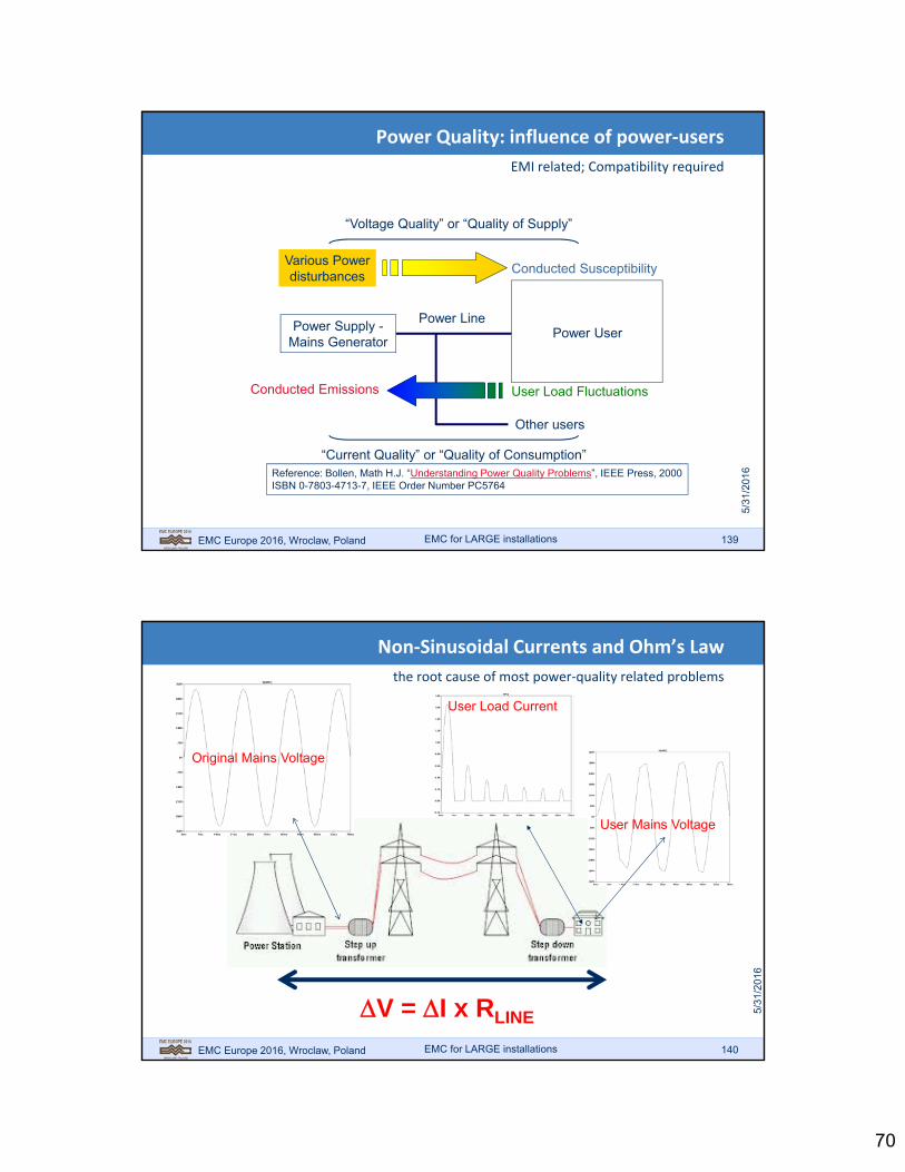
Power Quality: influence of power‐users
EMI related; Compatibility required
Power LinePower Supply -
Mains GeneratorPower User
Conducted Emissions
Conducted Susceptibility
Other users
Various Powerdisturbances
User Load Fluctuations
“Voltage Quality” or “Quality of Supply”
“Current Quality” or “Quality of Consumption”Reference: Bollen, Math H.J. “Understanding Power Quality Problems”, IEEE Press, 2000ISBN 0-7803-4713-7, IEEE Order Number PC5764
EMC for LARGE installations
EMC Europe 2016, Wroclaw, Poland 140
Non‐Sinusoidal Currents and Ohm’s Law
the root cause of most power‐quality related problems
Original Mains Voltage
User Mains Voltage
User Load Current
V = I x RLINE
EMC for LARGE installations

71
EMC Europe 2016, Wroclaw, Poland 141
Mains Voltage and Current as Users Like to See It
clean sine wave voltage and resistive load
EMC for LARGE installations
EMC Europe 2016, Wroclaw, Poland 142
History: Reactive Loads
result: phase shift, cosine()
re
im
true or real power
rea
ctiv
e p
ow
er
EMC for LARGE installations

72
EMC Europe 2016, Wroclaw, Poland 143
Today: Non‐Linear Loads
most prominent: diodes charging bulk capacitors
Mains Voltage
Mains Current
Legend
EMC for LARGE installations
EMC Europe 2016, Wroclaw, Poland 144
Modern Compact Fluorescent Lamp (CFL)
electronic circuit with diode bridge and bulk capacitor
Diode Bridge
Bulk Capacitor Current Waveformon a “Decent” Sine-Shaped
Voltage Waveform
Source: Wikipedia
EMC for LARGE installations

73
EMC Europe 2016, Wroclaw, Poland 145
Problem with Diode Rectifiers: Synchronicity
all conduct simultaneously on mains voltage! distortion adds up
Same Fluorescent Lampin Large Office Buildingwith distorted Voltage
EMC for LARGE installations
EMC Europe 2016, Wroclaw, Poland 146
Small Users <75 W Have No PF Requirements
e.g. all LED’s , CFL’s and many laptops are exempt
Wave-Shape in Large Office Building: Multiple Zero Crossings!
Effect….Heavily DistortedVoltage Waveform
Multiple Zero Crossings
This effect iscalled:HarmonicDistortion
EMC for LARGE installations
74
EMC Europe 2016, Wroclaw, Poland 147
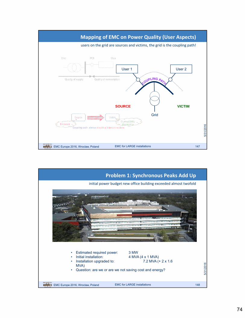
Mapping of EMC on Power Quality (User Aspects)
users on the grid are sources and victims, the grid is the coupling path!
Source Victimcoupling pathcoupling path
Coupling path: always electrical interconnectionsEmission
Susceptibility(Immunity)
Grid
User 2User 1
SOURCE VICTIM
EMC for LARGE installations
EMC Europe 2016, Wroclaw, Poland 148
Problem 1: Synchronous Peaks Add Up
initial power budget new office building exceeded almost twofold
• Estimated required power: 3 MW• Initial installation: 4 MVA (4 x 1 MVA)• Installation upgraded to: 7.2 MVA (+ 2 x 1.6
MVA)• Question: are we or are we not saving cost and energy?
EMC for LARGE installations

75
EMC Europe 2016, Wroclaw, Poland 149
Problem 2: Switcher Frequencies Pollute Environment
low power fast switching requires short risetime IGBT’s and MOSFETs S
ourc
e:Y
ouT
ube
EMC for LARGE installations
EMC Europe 2016, Wroclaw, Poland 150
Problem 3: Power Islands: Overproduction
mains voltage too high at high illumination levels
>253 VAC@ 45 KVAgeneration
EMC for LARGE installations

76
EMC Europe 2016, Wroclaw, Poland 151
Mechanism of Overvoltage at Sunny Days: Ohm’s Law
farm’s powercable cannot handle 45 KVA in the opposite direction
400V/10kV
2.5 km
R R
∆ 2
EMC for LARGE installations
EMC Europe 2016, Wroclaw, Poland 152
What if all Neighbours Install Solar Panels?
like the little lamp‐currents, many small ones make one big one!
EMC for LARGE installations

77
EMC Europe 2016, Wroclaw, Poland 153
How to Solve these Conflicts?
supply and demand, storage, who is in control? the Smart Grid!
Traditional: One Way Traffic
Now: Everybody can Supply or Use
EMC for LARGE installations
EMC Europe 2016, Wroclaw, Poland 154
Coffee Break
EMC for LARGE installations

78
EMC Europe 2016, Wroclaw, Poland 155
The Current Boundary
a provision to split loops (and shut out noise sources)
“Ground 1” “Ground 2”
Icm (noise current)
loop closes through “ground”
“Ground 2”“Ground 1”Icm
loop closes through “ground”
Create one or more “inner-loops”Short
circuit(s)
reduce looparea
check
Unit 1
Unit 2
(Mains cord 1)(Mains cord 2)(I/O cable 1-2)
Situation in practicedetector:AM-radio
EMC for LARGE installations
EMC Europe 2016, Wroclaw, Poland 156
Install current boundaries at natural interfaces
edge of PCB, cabinet wall, basement of a building; one boundary per unit!
Right Wrong
Icm Icm
Drawbacks:
Current follows longpath over equipment
Loop area cannot easilybe minimized
EMC for LARGE installations

79
EMC Europe 2016, Wroclaw, Poland 157
Examples of current boundaries on equipment
wide conductors and low‐resistance transitions (be careful with paint) !
protect all units with a current boundary!(and check any conductor that passes it)
Short
Wid
e
check DC resistance witha milli- meter: < 1 m!
NoPaint!
EMC for LARGE installations
EMC Europe 2016, Wroclaw, Poland 158
Use Current Boundary to protect existing “pig‐tail”
pig‐tails can be acceptable as long as CM currents are kept away from it
Icm
H-fieldlines
Wide metal plate
(Current Boundary)
EMC glands
EMC for LARGE installations

80
EMC Europe 2016, Wroclaw, Poland 159
If many Cables are Guided through Shielding Wall..
other options exist
EMC for LARGE installations
EMC Europe 2016, Wroclaw, Poland 160
Roxtec / Brattberg Glands
EMC for LARGE installations

81
EMC Europe 2016, Wroclaw, Poland 161
Special Gland System: Many Cables Through Wall
all make good electrical contact in wall (< 10 m)
current boundary 3
Wal
l of
Eq
uip
men
t R
oo
m
Roxtec
Brattberg
MonitoringProbe
Analyserw. TrackingGenerator
Amplifier
InjectionProbe
Wa
ll o
f E
qu
ipm
ent
Ro
om
MIL-STD-1310H
EMC for LARGE installations
EMC Europe 2016, Wroclaw, Poland 162
Next: Separate Cableswith Current Boundaries
classify cables into categories
Model
ICM
Category
red = “source” =“Emission”
1. Noisy (E)
green =“sensitive” =“Immunity”
2. Sensitive (I)
blue =“indifferent” =
“Neutral”
3. Indifferent (N)
E
I N
EMC for LARGE installations

82
EMC Europe 2016, Wroclaw, Poland 163
Model the Real System in CM loops
Both sensitive (analog, various busses) and (polluted) power lines
M3~
Process control system
powerelectronics
relay’s circuitbreakers
pumps,fans, drives
pneumatic/hydraulic
valves
sensorsProduction process / machine
Controlequipment
Power supply 10 kV/400 V
Industrial Environment
I/Omodule
controlequipmentPLC/PC/Ccontrol buscontrol bus
CP
U b
us
machine structure
Source: C.J. Post “EMC of Large Systems” PATO 2007
EMC for LARGE installations
EMC Europe 2016, Wroclaw, Poland 164
1. herken kringN
Steps:
Separating Cables with Current Boundaries
use Neutral conductor to reduce loop area; then insert current boundary
1. recognize loop
E
I2. reduce looparea
N
3. add boundary
EMC for LARGE installations
83
EMC Europe 2016, Wroclaw, Poland 165
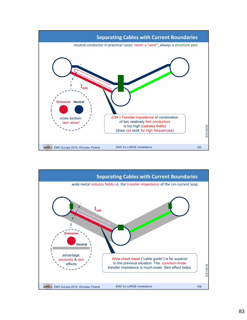
Separating Cables with Current Boundaries
neutral conductor in practical cases: never a “wire”, always a structure part
cm
cross section:twin wires!
Emission Neutral
(CM-) Transfer impedance of combinationof two relatively thin conductors
is too high (radiates fields)(does not work for high frequencies)
EMC for LARGE installations
EMC Europe 2016, Wroclaw, Poland 166
Separating Cables with Current Boundaries
wide metal reduces fields i.e. the transfer‐impedance of the cm‐current loop
cm
advantage:proximity & skin
effects
Emission
Neutral
Wide sheet metal (“cable guide”) is far superiorto the previous situation. The common-mode
transfer impedance is much lower. Skin effect helps.
EMC for LARGE installations

84
EMC Europe 2016, Wroclaw, Poland 167
Separating Cables (Alternative)
use structure metal parts to “guide” cables and insert current boundaries
N Steps:1. recognize loop
E
I
2. guide cables with metal strips or trays
3. connect current boundaries to strips
EMC for LARGE installations
EMC Europe 2016, Wroclaw, Poland 168
Separating Cables with Current Boundaries
use (Ground‐) Plane to reduce loop area; then insert current boundaries
NSteps:1. recognize loop
E
I
2. cover loop with metal (ground-)plane
3. connect current boundaries to plane
Note: we are actuallyreducing CM-loop areashere, using wide metal “short-circuits”
EMC for LARGE installations

85
EMC Europe 2016, Wroclaw, Poland 169
“Plane” could be metal mesh
Separating Cables with Current Boundaries
instead of a metal plane a metal mesh could be used
N
E
I
EMC for LARGE installations
wavelength is key to mesh size:apertures should be very smallwith respect to ¼ wavelength ()
EMC Europe 2016, Wroclaw, Poland 170
Transfer Impedance improvement
mechanism identical to the single wire case
EMC for LARGE installations
source (50)
scope
Cable 1 (source)
Cable 2 (passive)
50
B
50
A ICM (=noise)
(proximity effect)Icm “squeezes”
under cable

86
EMC Europe 2016, Wroclaw, Poland 171
Use available metal to “short‐out” CM‐currents
e.g. a ship’s deck and walls can be used as groundplane(s)
Important: keep cables near metal over their full length!(unless cables have sufficient shielding to go “unprotected”)
UNPROTECTED
PROTECTED
Good contact(< 1 m)
Goodcontact
?!
EMC for LARGE installations
EMC Europe 2016, Wroclaw, Poland 172
Cable distance is important
once a cable guide is used for protection
H
D
Current distribution of cm in cable guide ismeasure of flux density, , coupling into
cable: at source ~L, at victim ~M!
cm
sourcesourceL
cm
victim
victim
sourceM
proximity effect
closer cable“catches” more flux
Source:Johnson, H“High-SpeedDigital Design”1993
2
1
HD
LM source
2
1
1
HDL
Mk
source
COUPLING FACTOR: k
EMC for LARGE installations

87
EMC Europe 2016, Wroclaw, Poland 173
Two Types of Current Boundaries
Short Circuit for Common‐Mode “Sources”
Enclosure / EMC Cabinet / Shielded Room
Environment Region “0”
Environment Region “1”
1. Connector Plate
EMC for LARGE installations
EMC Europe 2016, Wroclaw, Poland 174
Three Types of Current Boundaries
Short Circuit for Common‐Mode “Sources”
3. CompletelyShielded
EnclosureEnclosure / EMC Cabinet / Shielded Room
Environment Region “1”
1. Connector Plate
Environment Region “0”
EMC for LARGE installations
88
EMC Europe 2016, Wroclaw, Poland 175
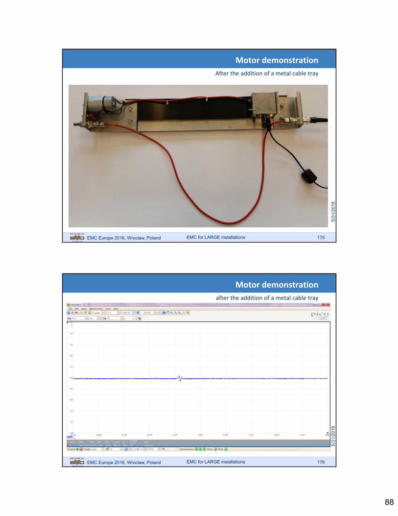
Motor demonstration
After the addition of a metal cable tray
EMC for LARGE installations
EMC Europe 2016, Wroclaw, Poland 176
Motor demonstration
after the addition of a metal cable tray
EMC for LARGE installations
89
EMC Europe 2016, Wroclaw, Poland 177
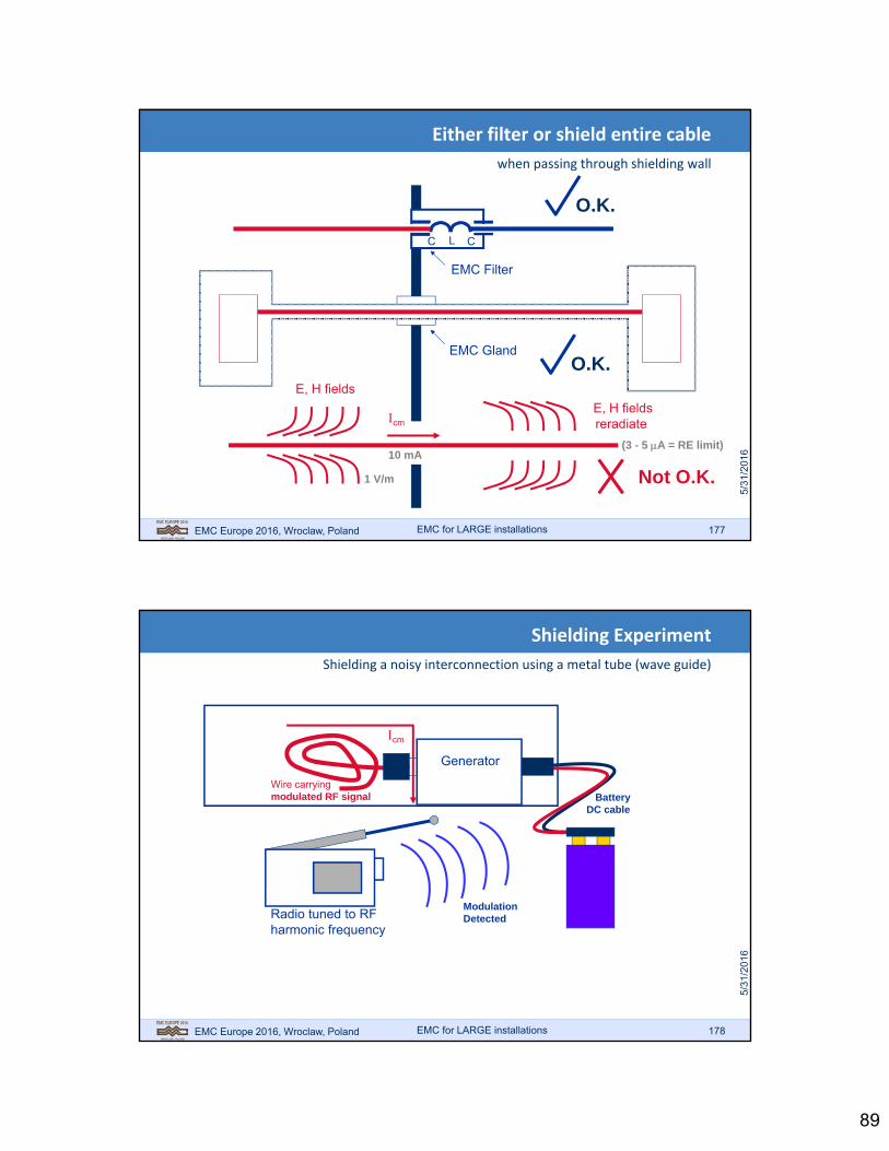
Either filter or shield entire cable
when passing through shielding wall
EMC Gland
C L C
EMC Filter
O.K.
O.K.
Not O.K.
cm
E, H fields
E, H fieldsreradiate
1 V/m
10 mA(3 - 5 A = RE limit)
EMC for LARGE installations
EMC Europe 2016, Wroclaw, Poland 178
Shielding Experiment
Shielding a noisy interconnection using a metal tube (wave guide)
Wire carryingmodulated RF signal Battery
DC cable
Generator
Radio tuned to RFharmonic frequency
ModulationDetected
cm
EMC for LARGE installations

90
EMC Europe 2016, Wroclaw, Poland 179
Shielding Experiment
Entering a conductor into tube couples out the noise again
Wire carryingmodulated RF signal Battery
DC cable
Generator
Radio tuned to RFharmonic frequency
ModulationDetected
EMC for LARGE installations
EMC Europe 2016, Wroclaw, Poland 180
Shielding Experiment
Insulating generator case: battery cable now reradiates noise (antenna)
Wire carryingmodulated RF signal Battery
DC cable
Generator
Radio tuned to RFharmonic frequency
ModulationDetected
cm
EMC for LARGE installations

91
EMC Europe 2016, Wroclaw, Poland 181
Shielding Experiment
Entering a screened conductor into tube also couples out the noise again
Wire carryingmodulated RF signal Battery
DC cable
Generator
Radio tuned to RFharmonic frequency
ModulationDetected
grounding wire
EMC for LARGE installations
EMC Europe 2016, Wroclaw, Poland 182
Shielding Experiment
Grounding the shield with the wire does not solve the interference problem!
Wire carryingmodulated RF signal Battery
DC cable
Generator
Radio tuned to RFharmonic frequency
ModulationDetected
EMC for LARGE installations

92
EMC Europe 2016, Wroclaw, Poland 183
Shielding Experiment
Cable shield must be grounded directly to the metal shield to stop the noise
Wire carryingmodulated RF signal Battery
DC cable
Generator
Radio tuned to RFharmonic frequency
ModulationDetected
EMC for LARGE installations
EMC Europe 2016, Wroclaw, Poland 184
Bad “Grounding” habits
it is Inductance, not the milliOhms that count!
EMC for LARGE installations

93
EMC Europe 2016, Wroclaw, Poland 185
Shielding Experiment
A filter in the inserted wire does not help if only grounded with a wire
Wire carryingmodulated RF signal Battery
DC cable
Generator
Radio tuned to RFharmonic frequency
ModulationDetected
EMC for LARGE installations
EMC Europe 2016, Wroclaw, Poland 186
Shielding Experiment
only when the wide metal filter plate touches, the shielding works
Wire carryingmodulated RF signal Battery
DC cable
Generator
Radio tuned to RFharmonic frequency
EMC for LARGE installations

94
EMC Europe 2016, Wroclaw, Poland 187
Filter = “Frequency Dependent” Current Boundaries
EMI filter is usually employed as frequency dependent current boundary
L
N
PE
L‘
N’
LINE LOAD
CX CX
CY CYR
ble
ed
L
L
EMC for LARGE installations
EMC Europe 2016, Wroclaw, Poland 188
• Example of intended segregation of power supply
• Alternative in case of shared power supply: power supply filter
Conducted emission via power supply
EMC for LARGE installations

95
EMC Europe 2016, Wroclaw, Poland 189
Power supply
M1) Earthing of filter and drive
filter FC
Power supply
M
2) Inductive coupling between in- and output of filter
filterFC
Power supply
MOK
FCfilter
Installation of filter
EMC for LARGE installations
EMC Europe 2016, Wroclaw, Poland 190
50
50
50
50
Source: Goedbloed
Filter demo
EMC for LARGE installations

96
EMC Europe 2016, Wroclaw, Poland 191
Examples of bad installation practice of filters
Inductive coupling between input and output wiring makes the filter ineffective segregate input and output wiring
EMC for LARGE installations
EMC Europe 2016, Wroclaw, Poland 192
Installation of mains RFI and output filters
Source: Danfoss
Installation of shielded motor cable and cable termination details
Source: ABB
Vendor EMC installation requirements
EMC for LARGE installations

97
EMC Europe 2016, Wroclaw, Poland 193
Large number of switched applications (motors, valves etc.)
No EMC requirements for single component
Disturbing potential is determined by reactive properties of load, cable lengths, switching frequency and supply voltage
Emission standard for switching transients (clicks) not up to date (based on radio interference (CISPR), whereas immunity of digital circuits, field buses etc. is the main issue.
Installations with switched loads (transients)
EMC for LARGE installations
EMC Europe 2016, Wroclaw, Poland 194
Continuous emissions
Transient emission
EN-IEC 61000-6-4: generic emission standard for industrial environment
Emission as per EN-IEC 61000-6-4
EMC for LARGE installations
98
EMC Europe 2016, Wroclaw, Poland 195
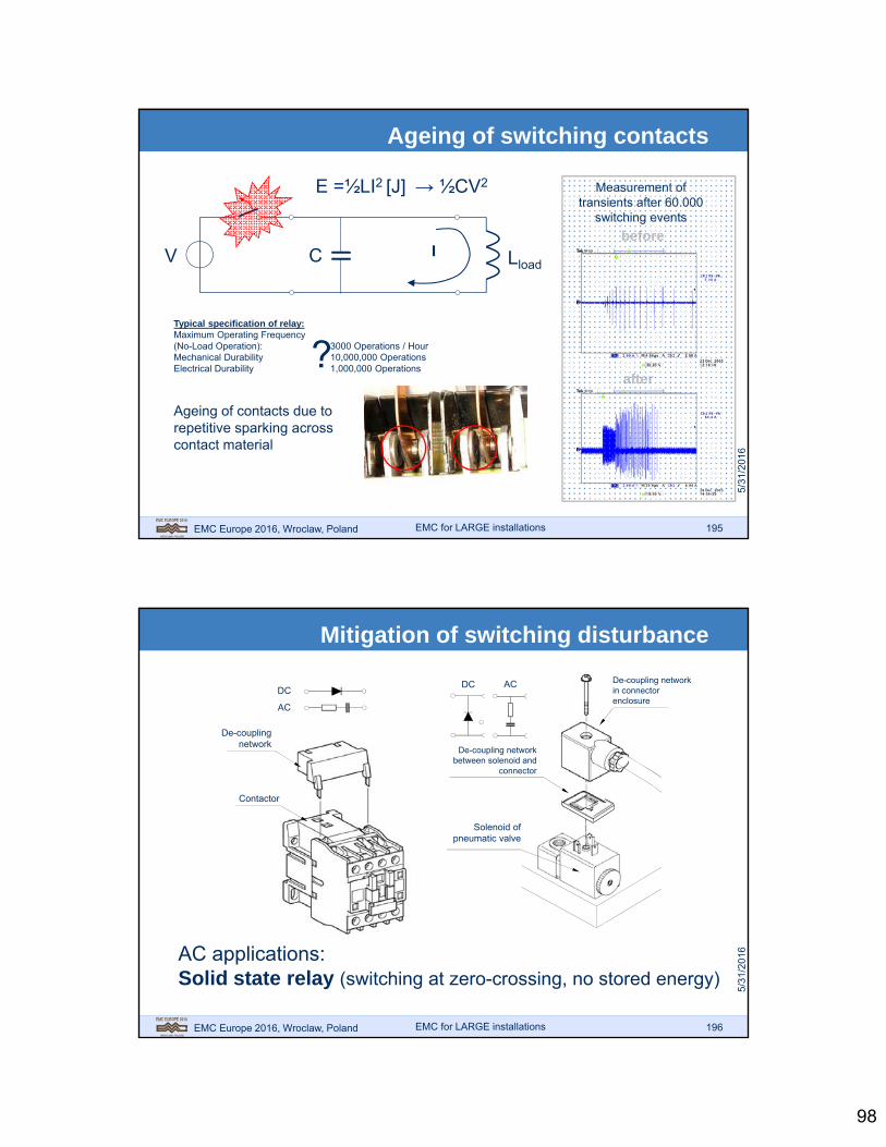
LloadI
E =½LI2 [J] → ½CV2
V C
Typical specification of relay: Maximum Operating Frequency (No-Load Operation): 3000 Operations / HourMechanical Durability 10,000,000 OperationsElectrical Durability 1,000,000 Operations?Ageing of contacts due to repetitive sparking across contact material
before
Measurement of transients after 60.000
switching events
after
Ageing of switching contacts
EMC for LARGE installations
EMC Europe 2016, Wroclaw, Poland 196
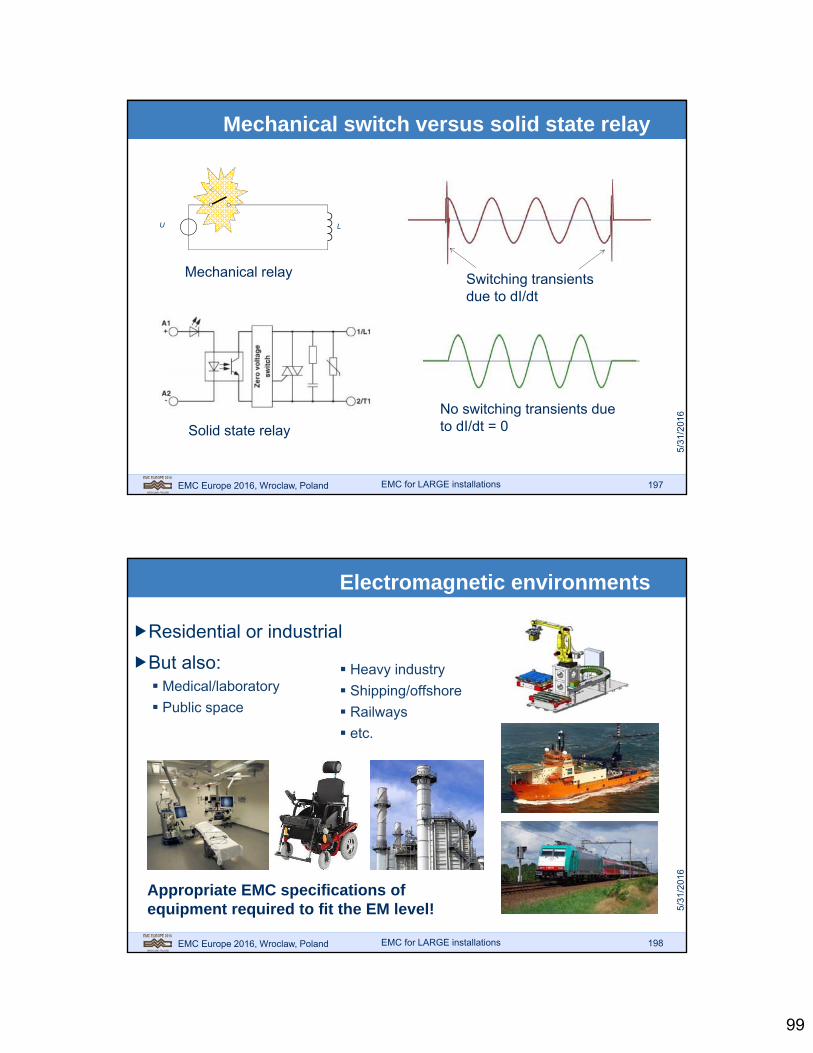
DC AC
De-coupling network between solenoid and
connector
Solenoid of pneumatic valve
DC
AC
Contactor
De-coupling network in connector enclosure
De-coupling network
AC applications: Solid state relay (switching at zero-crossing, no stored energy)
Mitigation of switching disturbance
EMC for LARGE installations
99
EMC Europe 2016, Wroclaw, Poland 197
L
Mechanical relay
U
Switching transients due to dI/dt
Solid state relay
No switching transients due to dI/dt = 0
Mechanical switch versus solid state relay
EMC for LARGE installations
EMC Europe 2016, Wroclaw, Poland 198
Electromagnetic environments
Residential or industrial
But also: Medical/laboratory
Public space
Heavy industry
Shipping/offshore
Railways
etc.
Appropriate EMC specifications of equipment required to fit the EM level!
EMC for LARGE installations

100
EMC Europe 2016, Wroclaw, Poland 199
HV area
4
Production plant
3
Office
2
5
Interfaces between EM levels
Installation measures
IEC: 1. very sensitive2. sensitive, domestic / office3. disturbing/noisy, industrial4. very disturbing/noisy, heavy industry5. exception disturbance
1Laboratory
Electromagnetic zones in large installations
EMC for LARGE installations
EMC Europe 2016, Wroclaw, Poland 200
ZONE 3 INDUSTRIAL
ENVIRONMENT
ZONE 2PROTECTED
ENVIRONMENT
ZONE 1WELL PROTECTED ENVIRONMENT
(E.G. EQUIPMENT CABINET)
ELECTRICAL EQUIPMENT
AND INSTRUMENTS
BARRIER BUILDING CONSTRUCTION
(E.G. CONCRETE
REINFORCEMENT
BARRIER STEEL
EQUIPMENT
CABINET = EMC MEASURE AT
BARRIER (BONDING OF
ARMOURED CABLES, FILTERING OF NON-ARMOURED CABLES)
► Specify EM levels for equipment in various EM environments► Specify interfaces between EM zones► Similar to LPZ (Lightning Protection Zones) in EN-IEC-62305-3 and -4
EM zones
EMC for LARGE installations

101
EMC Europe 2016, Wroclaw, Poland 201
Control building of plant
cable entry framebonded to concrete
reinforcement
cable trenchwith PEC
concretereinforcement
grid
welded earthingand bonding grid
5 x 5 mAir termination network
bonded to column re-bar
bonding ofcable duct
reinforcement offoundation
wire-lashing details:
1. twisted soft steelwire
2. steel-reinforcingbars andearthing andbonding grid
1
2
1
2
foundation re-barbonded to
column re-bar
Building observed through spectacles
EMC spectacles
Required:
Different look at civil engineering
EMC for LARGE installations
EMC Europe 2016, Wroclaw, Poland 202
Cable entry of building
EMC for LARGE installations

102
EMC Europe 2016, Wroclaw, Poland 203
Current barrier at cable entry of Faraday Cage
Radio receiver
=c/f = 3.108 / f[m] =300 / f[MHz]
f=100MHz (=3m)Mesh size: 1x1mm
f=1MHz (=300m)Mesh size: 10x10cm
Demo cable entry
EMC for LARGE installations
EMC Europe 2016, Wroclaw, Poland 204
Planning of concrete reinforcement bonding
EMC for LARGE installations

103
EMC Europe 2016, Wroclaw, Poland 205
springclip
Cable entry inside (bonding of shield to cage)
EMC for LARGE installations
EMC Europe 2016, Wroclaw, Poland 206
Shielding clamps at panel entry
Gland plate
Cable entry in equipment panel
EMC for LARGE installations
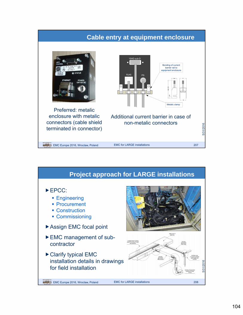
104
EMC Europe 2016, Wroclaw, Poland 207
RJ45
15HD sub-D
PS
Metalic clamp
Bonding of current barrier rail to
equipment enclosure
Preferred: metalic enclosure with metalic
connectors (cable shield terminated in connector)
Additional current barrier in case of non-metalic connectors
Cable entry at equipment enclosure
EMC for LARGE installations
EMC Europe 2016, Wroclaw, Poland 208
EPCC: Engineering Procurement Construction Commissioning
Assign EMC focal point
EMC management of sub-contractor
Clarify typical EMC installation details in drawings for field installation
Project approach for LARGE installations
EMC for LARGE installations
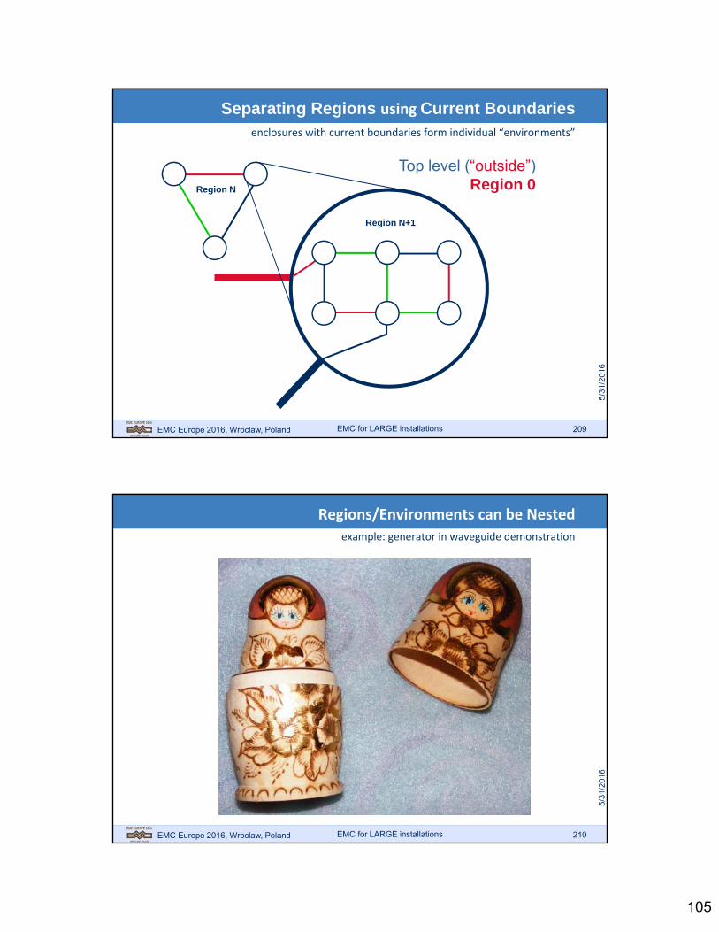
105
EMC Europe 2016, Wroclaw, Poland 209
Separating Regions using Current Boundariesenclosures with current boundaries form individual “environments”
Region N
Region N+1
Top level (“outside”)Region 0
EMC for LARGE installations
EMC Europe 2016, Wroclaw, Poland 210
Regions/Environments can be Nested
example: generator in waveguide demonstration
EMC for LARGE installations

106
EMC Europe 2016, Wroclaw, Poland 211
Only Limited Shielding can be achieved per Enclosure
20 ‐40 [dB]; but it can be applied recursively!
In EMC terms,sometimes referred to as:Multipoint Grounding…
EMC for LARGE installations
EMC Europe 2016, Wroclaw, Poland 212
Regions are defined Electromagnetic Environments
(example) region 0: MIL‐STD‐464A, region 1: bridge, region 2: below deck
0
1
2
Aim: use commercial equipment in region 2 (susceptibility level 10 V/m)
Shielding between successive regions: 20 - 40 dB (factor 10 to 100)
Define where EM zones will be Define the EM levels per region Use adequate current boundaries between regions
EMC for LARGE installations

107
EMC Europe 2016, Wroclaw, Poland 213
Multipoint Grounding
hierarchy of current boundaries
PCB withground plane
current boundary 1
current boundary 2
Cabinet with Back-plane
Connector Plate
on Cabinet Wall
EMC for LARGE installations
EMC Europe 2016, Wroclaw, Poland 214
Multipoint Grounding
separating rooms in a ship is called Zoning (partitioning into EM‐Regions)
current boundary 2
current boundary 3
Cabinet Wall
Wall of Equipment Room
PCB 1 PCB 21
backplane 1
2
cabinet 1
3
room wall
4
cabinet 2
5
backplane 2
20 dB per boundary:= 100 dB!
EMC for LARGE installations

108
EMC Europe 2016, Wroclaw, Poland 215
Voltage Dependent Current Boundaries
varistors and tranzorbs are often used to absorb DM or CM spikes
Example from IEC 62305 part 4 (Annex C)
SPD1 SPD2 SPD3
500
volt
age
[V]
time [s]0
1
volt
age
[V]
time [s]0
1
volt
age
[V]
time [s]0
1
Source: Jasper J. Goedbloed, “EMC”Prentice Hall/Kluwer 1992note: 1 [m] cable 1 H
EMC for LARGE installations
EMC Europe 2016, Wroclaw, Poland 216
Try to stick to the “Low Frequency Approach”
use current boundaries to restrain sizes to way below half‐wavelength
Large ScaleLow Frequencies
Small ScaleHigh Frequencies
EMC for LARGE installations
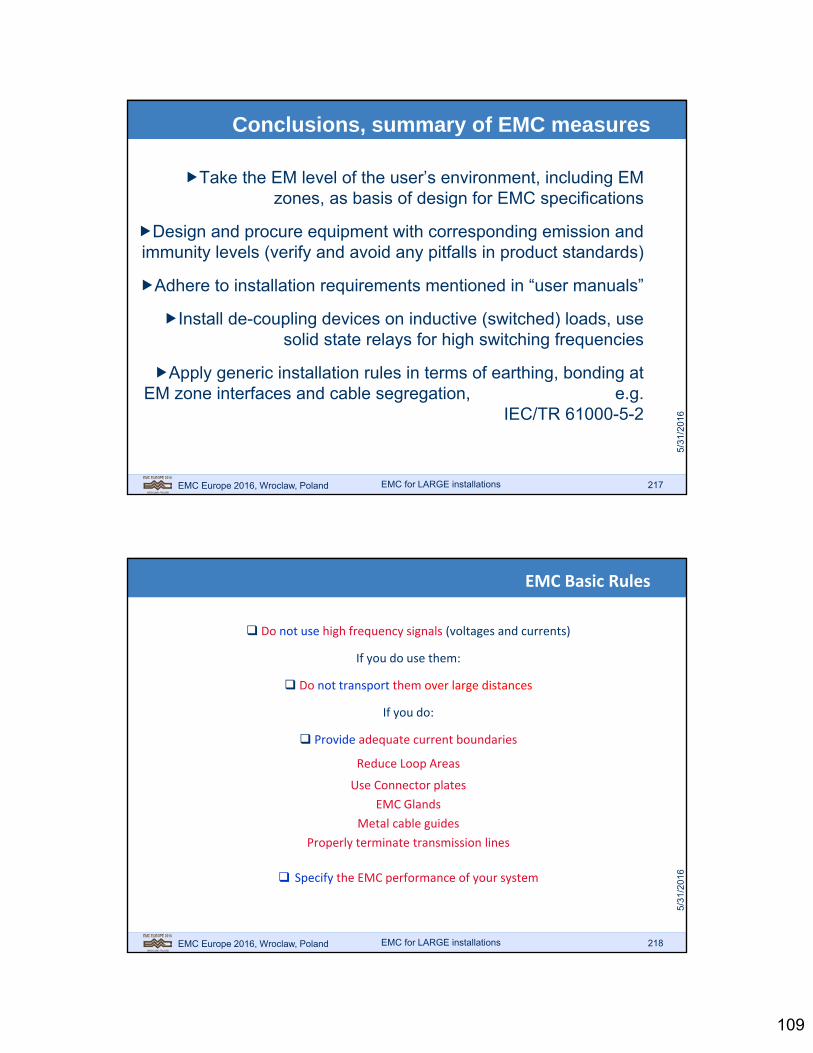
109
EMC Europe 2016, Wroclaw, Poland 217
Conclusions, summary of EMC measures
Take the EM level of the user’s environment, including EM zones, as basis of design for EMC specifications
Design and procure equipment with corresponding emission and immunity levels (verify and avoid any pitfalls in product standards)
Adhere to installation requirements mentioned in “user manuals”
Install de-coupling devices on inductive (switched) loads, use solid state relays for high switching frequencies
Apply generic installation rules in terms of earthing, bonding at EM zone interfaces and cable segregation, e.g.
IEC/TR 61000-5-2
EMC for LARGE installations
EMC Europe 2016, Wroclaw, Poland 218
EMC Basic Rules
Do not use high frequency signals (voltages and currents)
If you do use them:
Do not transport them over large distances
If you do:
Provide adequate current boundaries
Reduce Loop Areas
Use Connector plates
EMC Glands
Metal cable guides
Properly terminate transmission lines
Specify the EMC performance of your system
EMC for LARGE installations

110
EMC Europe 2016, Wroclaw, Poland 219
“Systems Designers Heaven”
independent building blocks with “abstract” behaviour
System
Software
HardwareModules
Components
Object Oriented
realise complex from simpler behaviour
make assemblies independent
solve “undesired” as low as possible
EMC Principal Laws No high frequencies Do not transport them Use adequate boundaries
EMC for LARGE installations
EMC Europe 2016, Wroclaw, Poland 220
Two ways to achieve EMC: 1. The Crisis Approach
“Build the plane, push it off the cliff, let it crash and start all over again”
Sou
rce:
You
Tub
e
EMC for LARGE installations

111
EMC Europe 2016, Wroclaw, Poland 221
2. The “Systems Approach”
Consider EMC right from the start throughout the design
0
manyA
vaila
ble
Miti
gatio
n O
ptio
ns
Concept Design Manufacture Test Operational
Requirements
Measures
0
M$$
Cos
t of
Mod
ifica
tion
Check bonding
Repair/redesign
Bankruptcy
phase in the lifecycle
EMC for LARGE installations
EMC Europe 2016, Wroclaw, Poland 222
Four Key Elements
of EMC implementation in large organizations
1. Awareness
2. Network
3. Rules & Guidelines
4. Program support
EMC for LARGE installations
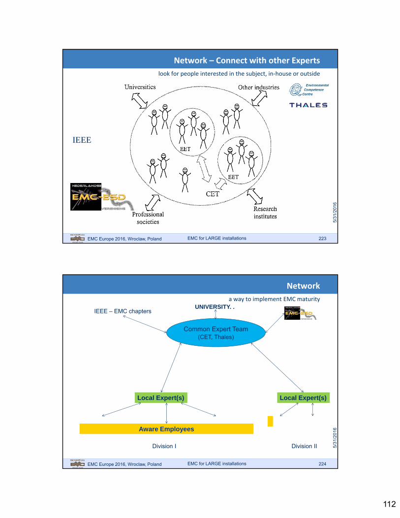
112
EMC Europe 2016, Wroclaw, Poland 223
Network – Connect with other Experts
look for people interested in the subject, in‐house or outside
IEEE
EMC for LARGE installations
EMC Europe 2016, Wroclaw, Poland 224
Network
a way to implement EMC maturity
Aware Employees
Local Expert(s) Local Expert(s)
Common Expert Team(CET, Thales)
Division I Division II
UNIVERSITY. . IEEE – EMC chapters
EMC for LARGE installations

113
EMC Europe 2016, Wroclaw, Poland 225
Build EMC assurance through the Knowledge Cycle
insert electro magnetic behavior up front
Problem definition:“desired behavior”
Research/Analyses
Behavioral Model
Validatedmodels
KnowledgeTransfer &Education
DevelopmentSupport
Validation/Verification
“Test”
EMC for LARGE installations
EMC Europe 2016, Wroclaw, Poland 226
EMC Rules and Guidelines
a lot of information on EMC engineering can be found on the internet
EMC for LARGE installations

114
EMC Europe 2016, Wroclaw, Poland 227
Rules and Guidelines
a lot of good literature is available on the internet
http://genesis.ee.auth.gr/dimakis/egatastaseis/groupe%20schneider/cashier%20techn/ECT149.pdf
http://www.eschneider.pl/download/10%20Poradniki/EMC.pdf
Or try one of the EMC “Cahiers Technique” e.g. #149:
http://www.humerboard.at/ftkl/Design_Techniques_For_%20EMC.pdf
http://literature.rockwellautomation.com/idc/groups/literature/documents/rm/gmc-rm001_-en-p.pdf
EMC for LARGE installations
EMC Europe 2016, Wroclaw, Poland 228
EMC Rules and Guidelines
or: buy a book!
ISBN 978-0-470-18930-6
EMC for LARGE installations

115
EMC Europe 2016, Wroclaw, Poland 229
Product Development/Program Support
manage the implementation of “EMC” into your system
EMC for LARGE installations
F. Leferink, S. Lerose, M. Sauvageot, W. van Etten “The Four Key Elements of EMC Implementation in Large Organizations” EMC Europe, 2002, Sorrento Italy. A. Roc’h, F. Leferink, “An Audit Tool for the Implementation of EMC in Large Companies”, EMC Europe, 2012, Roma Italy.
EMC Europe 2016, Wroclaw, Poland 230
Product Development/Program Support
how to? Look e.g. at MIL‐HDBK‐237B
http://everyspec.com/MIL-HDBK/MIL-HDBK-0200-0299/MIL-HDBK-237B_21779/
EMC for LARGE installations

116
EMC Europe 2016, Wroclaw, Poland 231
Product Development/Program Support
perform engineering & qualification tests
http://www.thales-ecc.nl/onze-expertise/emc/
EMC for LARGE installations
Click to edit Master title style
EMC Europe 2016, Wroclaw, Poland 232
Further questions?
EMC Europe 2016 Wroclaw International Symposium and Exhibition on Electromagnetic Compatibility September 5-9, 2016, Wroclaw, Poland
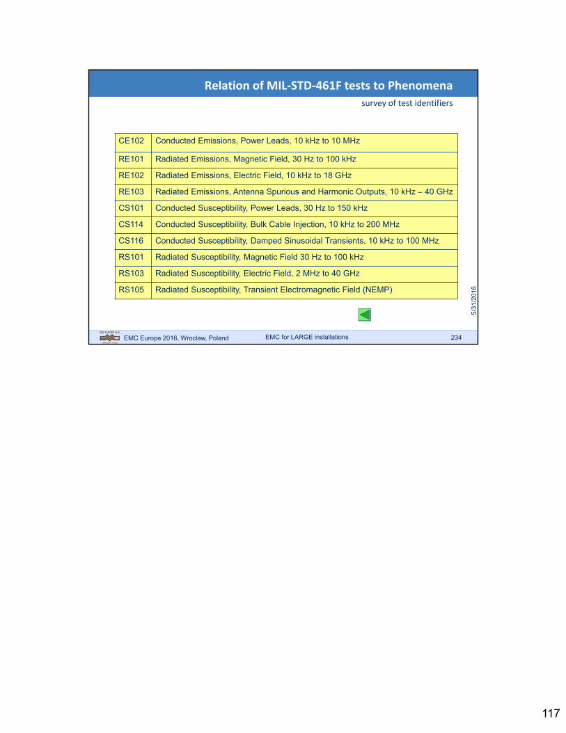
117
EMC Europe 2016, Wroclaw, Poland 234
Relation of MIL‐STD‐461F tests to Phenomena
survey of test identifiers
CE102 Conducted Emissions, Power Leads, 10 kHz to 10 MHz
RE101 Radiated Emissions, Magnetic Field, 30 Hz to 100 kHz
RE102 Radiated Emissions, Electric Field, 10 kHz to 18 GHz
RE103 Radiated Emissions, Antenna Spurious and Harmonic Outputs, 10 kHz – 40 GHz
CS101 Conducted Susceptibility, Power Leads, 30 Hz to 150 kHz
CS114 Conducted Susceptibility, Bulk Cable Injection, 10 kHz to 200 MHz
CS116 Conducted Susceptibility, Damped Sinusoidal Transients, 10 kHz to 100 MHz
RS101 Radiated Susceptibility, Magnetic Field 30 Hz to 100 kHz
RS103 Radiated Susceptibility, Electric Field, 2 MHz to 40 GHz
RS105 Radiated Susceptibility, Transient Electromagnetic Field (NEMP)
EMC for LARGE installations