Electromagnetic Interference/Compatibility (EMI/EMC) Control Test ...

Version 1.2
• Compatible Peer (PPRC)
• Compatible Extended (XRC)
• Compatible Native Flash (FlashCopy)
EMC® Compatibility Features for IBM Copy Services on z/OS

Copyright © 2016 EMC Corporation. All rights reserved.
EMC believes the information in this publication is accurate as of its publication date. The information is subject to change without notice.
THE INFORMATION IN THIS PUBLICATION IS PROVIDED “AS IS.” EMC CORPORATION MAKES NO REPRESENTATIONS OR WARRANTIES OF ANY KIND WITH RESPECT TO THE INFORMATION IN THIS PUBLICATION, AND SPECIFICALLY DISCLAIMS IMPLIED WARRANTIES OF MERCHANTABILITY OR FITNESS FOR A PARTICULAR PURPOSE.
Use, copying, and distribution of any EMC software described in this publication requires an applicable software license.
EMC2, EMC, and the EMC logo are registered trademarks or trademarks of EMC Corporation in the United State and other countries. All other trademarks used herein are the property of their respective owners.
For the most up-to-date regulator document for your product line, go to EMC Online Support (https://support.emc.com).
Part number H11173
2 EMC Compatibility Features for IBM Copy Services on z/OS TechBook

Contents
Preface
Chapter 1 Introduction
Overview ............................................................................................ 22
Assumptions ...................................................................................... 24 Terminology ............................................................................................25 GDPS deployment ............................................................................ 26 Compatibility ..................................................................................... 27 Enginuity features ............................................................................... 28 Compatible copy services technologies ......................................... 29 GDPS ........................................................................................... 29 Compatibility features............................................................... 30 Valid combinations for compatibility features ............................... 31
Chapter 2 GDPS Business Continuity Solutions
GDPS overview ................................................................................. 34
GDPS/PPRC ...................................................................................... 35 GDPS/HM ......................................................................................... 37 GDPS/XRC ........................................................................................ 38 GDPS/MzGM .................................................................................... 39 Unsupported GDPS architectures .................................................... 40 Common features of GDPS versions .............................................. 41 Supported GDPS Releases ........................................................ 41 NetView and system automation for z/OS components ..... 41 NetView operator ...................................................................... 41 SCRIPT language with TAKEOVER, CONTROL, and BATCH scripts ........................................................................... 42 GEOPARM and GEOXPARM storage policy definitions .... 43
EMC Compatibility Features for IBM Copy Services on z/OS TechBook
3
Contents
Policy Data Base (PDB) ............................................................. 43 Sysplex ........................................................................................ 44 K systems .................................................................................... 44
Documentation .................................................................................. 45 Advanced Copy Services .......................................................... 45 GDPS manuals ........................................................................... 45
Chapter 3 EMC Compatible Peer (PPRC) PPRC overview ................................................................................. 48 PPRC components ............................................................................ 49 SRDF/S operations and Compatible Peer. .................................... 51
External manifestation of the SRDF/S GROUP name .......... 51 Supported and non-supported PPRC modes ............................... 52 PPRC operation ................................................................................. 53 Supported PPRC features................................................................... 57
Metro Mirror and Global Copy ............................................... 57 PPRC Consistency Group ......................................................... 57 CRIT(Y) ....................................................................................... 59 PPRC/FlashCopy Consistency Group Timeout .................... 59 Volume pairs .............................................................................. 60 PPRC pathing ............................................................................. 60 Dependent write consistency ................................................... 63 CGROUP FREEZE/RUN and the preservation of dependent write consistency ....................................................................... 64 Failover Failback (FO/FB) ........................................................ 64 Link failure warning ................................................................. 65 MIDAW and PPRC .................................................................... 65 Query storage controller status................................................ 65 Summary event notification for PPRC suspends .................. 66 Storage controller health message ........................................... 67 CQUERY LINKINFO ................................................................ 67
PPRC TSO commands ...................................................................... 68 Other PPRC interfaces ...................................................................... 69 Compatible Peer versus SRDF/S and Adaptive Copy ................ 70 FAST and Compatible Peer ............................................................. 70 Compatible Peer limitations ............................................................ 70 Designing the solution for z/OS ..................................................... 71
PPRC Symmetrix system configuration specifications ......... 71 Volume Map PARMs ................................................................ 72 PPRC connectivity ..................................................................... 72 Security authorization ............................................................... 73 EMC PPRC link definition ........................................................ 73
4 EMC Compatibility Features for IBM Copy Services on z/OS TechBook

EMC Compatibility Features for IBM Copy Services on z/OS TechBook
Contents
Conversion from SRDF/S to PPRC emulation .............................. 74
Chapter 4 GDPS/PPRC GDPS/PPRC and GDPS/HyperSwap Manager (GDPS/HM) .. 76 GDPS/PPRC components ................................................................ 75 EMC DASD Support Matrix for GDPS/PPRC .............................. 79 GDPS/PPRC storage management functions ............................... 82 GEOPARM ................................................................................................ 83 Autonomic policies and GEOPLEX ................................................ 84 GEOPLEX options PRIMARYFAILURE ................................. 84 GEOPLEX options PPRCFAILURE ......................................... 85 Policy implications and remote copy definition .................... 87 FREEZE autonomic operation ......................................................... 88 Planned FREEZE ........................................................................ 88 GDPS/PPRC DASD script keywords ..................................... 89 Sharing VMAX DASD subsystems ................................................. 90 HyperSwap autonomic operations (unplanned HyperSwap) ... 91 Requirements .............................................................................. 91 GDPS with HyperSwap architecture ....................................... 93 Planned HyperSwap .................................................................. 96 HyperSwap RESYNCH ............................................................. 97 HyperSwap SUSPEND .............................................................. 97 HyperSwap TERMINATE ........................................................ 97 GDPS/PPRC DASD SWITCH HYPERSWAP SCRIPT keyword....................................................................................... 97 GDPS/HM HYPERSW commands for HyperSwap and recovery operations ................................................................... 98 FAST and HyperSwap ............................................................... 98 GDPS/PPRC DASD subsystem components ................................ 99 HCD definition with GDPS/PPRC .......................................... 99 GDPS K system LOCAL DASD resource ............................... 99 GDPS/PPRC utility device ..................................................... 100 LCU design ............................................................................... 100 GDPS/PPRC GEOPARM specification ........................................ 102 GEOPARM specifications unique to Symmetrix systems...102 GEOPARM coding ................................................................... 103 GEOPLEX links ........................................................................ 104 GEOPLEX MIRROR ................................................................. 105 GEOPLEX NONSHARE .......................................................... 106 Activation of a new GEOPARM (CONFIG) ......................... 107 FlashCopy with GDPS/PPRC ....................................................... 108 Justification ............................................................................... 108
5
Contents
Definition .................................................................................. 109 Operation .................................................................................. 109 With HyperSwap deployments ............................................. 110 Remote Pair FlashCopy .......................................................... 110
Symmetrix systems compatible feature licensing in GDPS/PPRC 111 CFHINT considerations .................................................................. 112 GDPS/PPRC operations ................................................................. 113
GDPS/PPRC mechanisms ...................................................... 113 Panel operations (GDPS operator) ........................................ 114
GDPS/PPRC DASD BATCH SCRIPT VPCEXIT2 ....................... 115 Locating PPRC error messages within GDPS/PPRC ................. 116
Search NetView’s log for messages ....................................... 116 Issuing MVS system commands from NetView .................. 116 Help ........................................................................................... 116
GDPS/PPRC employment of alternate subchannel support with Symmetrix systems .......................................................................... 117 Validating GDPS autonomic operations ...................................... 118
Unplanned FREEZE ................................................................ 118 Unplanned HyperSwap .......................................................... 119
GDPS/PPRC networking topologies ........................................... 120 EMC’s role ................................................................................ 120 GDPS topologies ...................................................................... 121 Link budget .............................................................................. 121 GDPS/PPRC BCRS .................................................................. 122 GDPS/PPRC FREEZE and GO/STOP .................................. 124 GDPS/PPRC with HyperSwap ............................................. 126
Chapter 5 Compatible Extended (XRC) Compatible Extended (XRC) overview ....................................... 130
Features and components ....................................................... 130 XRC components ............................................................................ 132 XRC planning overview checklist ................................................ 137 XRC operations ............................................................................... 139
XRC operations overview ....................................................... 139 Extended Remote copy data flow .......................................... 140 SDM Remote copy operations ............................................... 141 XRC Copy operations .............................................................. 141 XRC MONITOR I/O ............................................................... 142 XRC XADVANCE and XRECOVER operations .................. 142
Host time-stamping requirements .................................................. 144 Description of XRC components .................................................. 145
6 EMC Compatibility Features for IBM Copy Services on z/OS TechBook

EMC Compatibility Features for IBM Copy Services on z/OS TechBook
Contents
Symmetrix SIDEFILE ............................................................... 145 Sidefile resource management ............................................... 146 READERTIMEOUT value ....................................................... 148 Volume pairs ............................................................................. 149 Utility device ............................................................................. 150 SCSESSION and readers ......................................................... 150 Multi-readers ............................................................................ 151 Copy operations ....................................................................... 152 System Data Mover (SDM) address space ............................ 153 SDM buffers and memory requirements .............................. 155 System zResources ................................................................... 156 z/OS SDM systems .................................................................. 156 SDM sizing ................................................................................ 157 SDM scalability ......................................................................... 157 XRC parameters ....................................................................... 160 XRC PARMLIB hierarchy ....................................................... 169 XRC control data sets ............................................................... 170 XRC TSO commands ...................................................................... 173 Ordering XRC MC features for XRC implementations .............. 175 Designing an EMC XRC solution for z/OS ................................. 176 Implementation ........................................................................ 176 Sidefile specification ................................................................ 179 Symmetrix configuration file specifications ......................... 179 Linkage and channel extension connectivity ....................... 181 FICON linkage requirements ................................................. 182 XRC exploitation of PAVs. ...................................................... 183 Diagnostics: MODIFY ANTAS000 commands ............................ 185 XRC Performance Monitor (XPM) ................................................ 187
Chapter 6 GDPS/XRC GDPS/XRC overview ..................................................................... 190 GDPS/XRC features and operations ..................................... 190 GDPS/XRC components ......................................................... 190 GDPS/XRC systems and DASD components ............................. 196 Production systems/production sysplexs ............................ 196 GDPS/XRC sysplex ................................................................. 196 GDPS/XRC DASD ................................................................... 197 GDPS/XRC GEOXPARM mirroring defined .............................. 200 Locating XRC error messages with GDPS/XRC ......................... 201 Locating XRC XRECOVER report ................................................. 202 NetView operations ........................................................................ 203 Getting to GDPS from NetView operator console ............... 203
7

Contents
Browse NetView’s log ............................................................. 203 Search NetView’s log for messages ....................................... 203 Issuing MVS System Commands from NetView ................ 203
Chapter 7 Three-Site Solution GDPS/MzGM
GDPS/MzGM overview ................................................................ 206 MzGM architecture ........................................................................... 208 Terminology in GDPS MzGM ....................................................... 214 Symmetrix system compatible feature licensing in GDPS MzGM. 215 GDPS MzGM and XRC incremental re-synchronization ............ 216
Incremental resynchronization feature ................................. 216 Managing incremental resynchronization XRC sessions .. 216
Chapter 8 Compatible Native Flash for Mainframe
Compatible Native Flash for Mainframe overview ................... 220 Description of operation ................................................................ 221 Departures from IBM’s solution ................................................... 222
Supported FlashCopy functions ............................................ 222 Symmetrix split considerations ............................................. 222
FlashCopy components .................................................................. 223 Source volume .......................................................................... 223 Target volume .......................................................................... 224 FlashCopy session ................................................................... 224
FlashCopy modes of operation ..................................................... 225 FlashCopy COPY ..................................................................... 225 FlashCopy NOCOPY ............................................................... 226 FlashCopy INCREMENTAL .................................................. 226
FlashCopy Consistency Groups ...................................................... 227 Difference with PPRC CGROUP ........................................... 227 FlashCopy Consistency Group ................................................ 228 FlashCopy Freeze ....................................................................... 228 FlashCopy Thaw ...................................................................... 228
FlashCopy TSO commands ........................................................... 229 Symmetrix system configuration file settings ............................ 230
FlashCopy with GDPS/PPRC deployment ................................. 231 GDPS Managed FlashCopy .................................................... 231 Remote Pair FlashCopy .......................................................... 231
FlashCopy Considerations with XRC and GDPS/XRC deployment ...................................................................................... 233
Traditional DR testing without Zero Suspend FlashCopy. 233
8 EMC Compatibility Features for IBM Copy Services on z/OS TechBook

EMC Compatibility Features for IBM Copy Services on z/OS TechBook
Contents
DR Testing with Zero Suspend FlashCopy .......................... 233 Recovery for actual DR ............................................................ 235Additional FlashCopy considerations ................................... 236FlashCopy and XRC performance concerns during DR testing ........................................................................................ 237
Appendix A PPRC PATHing and Linkage Address
Link parameters ............................................................................... 240 Link parameters for VMAX 20K and 40K ............................. 240Defining PPRC PATHs with ICKDSF ................................... 242Link Parameters for VMAX3 and VMAX All Flash ............242
Appendix B EMC’s Role as a GDPS Storage Vendor New GDPS deployment ................................................................. 245 Supplementing an existing GDPS implementation .................... 247
Appendix C Sample GEOPARM (GEOXPARM) Overview .......................................................................................... 249 GDPS/PPRC GEOPARM .................................................................... 250
Appendix D GDPS/PPRC Support Matrix
Support matrix ................................................................................. 255
9

Contents
10 EMC Compatibility Features for IBM Copy Services on z/OS TechBook

Figures
1
PPRC components ........................................................................................... 49
2 Abbreviated PPRC states ............................................................................... 563 GDPS/PPRC components .............................................................................. 774 GDPS with HyperSwap architecture and DASD connectivity example 935 Batch TMP to trigger an unplanned GDPS/PPRC FREEZE ................... 1196 GDPS/PPRC BCRS architecture ................................................................. 1247 GDPS/PPRC FREEZE STOP/GO network provisioning with DWDM ......
1258 GDPS/PPRC with HyperSwap network ................................................... 1279 XRC components ........................................................................................... 13210 GDPS/XRC components .............................................................................. 19011 GDPS/MzGM architectural components .................................................. 20812 FlashCopy Components ............................................................................... 22313 Remote Pair FlashCopy Relationships ....................................................... 232
EMC Compatibility Features for IBM Copy Services on z/OS TechBook
11

Figures
12 EMC Compatibility Features for IBM Copy Services on z/OS TechBook

Tables
1
Allowable Compatible Extended copy combinations ................................ 31
2 Query DASD storage controller status comparison ................................... 663 PPRC TSO commands .................................................................................... 684 Symmetrix configuration settings for PPRC compatibility ....................... 715 EMC features for GDPS/PPRC implementation ...................................... 1116 Feature requirements and compatibility features ..................................... 1377 XRC PARMLIB recommendations .............................................................. 1628 XRC commands ............................................................................................. 1739 MC products for XRC implementation ...................................................... 17510 Symmetrix Configuration File Settings for XRC enablement ................. 18011 PAV enablement ............................................................................................ 18312 ANTAS000 command functions ................................................................. 18513 MC features for GDPS MzGM implementation ........................................ 21514 FlashCopy commands ................................................................................. 22915 Symmetrix Configuration File Settings for FlashCopy enablement ....... 23016 Symmetrix PPRC link parameter director map hex lookup .................... 24117 Support Matrix .............................................................................................. 256
EMC Compatibility Features for IBM Copy Services on z/OS TechBook
13

Tables
14 EMC Compatibility Features for IBM Copy Services on z/OS TechBook

Preface
Audience
This TechBook is intended as an introduction to EMC’s compatibility features for IBM’s Advanced Copy Services technologies. Its primary function is to provide EMC personnel and customers in pre-sales or early implementation activities a quick guide to the configuration and operations of PPRC, XRC, and FlashCopy compatibility features as they are supported by EMC. In addition, overview of common deployments of the Advanced Copy Services features and the degree of EMC’s compliance with those features is provided, noting when relevant departures in compatibility occur. This TechBook provides the reader with functional insight into EMC’s role in the deployment and operations of GDPS.
As part of an effort to improve and enhance the performance and capabilities of its product lines, EMC periodically releases revisions of its hardware and software. Therefore, some functions described in this document may not be supported by all versions of the software or hardware currently in use. For the most up-to-date information on product features, refer to your product release notes. If a product does not function properly or does not function as described in this document, contact your EMC representative.
This TechBook assumes some familiarity with the Symmetrix line of storage systems and EMC’s native remote copy technology. It is the intention of this manual to document the methodology of a remote copy implementation with EMC’s compatible copy services microcode features: pre-sales, customer consulting, GDPS implementation, and initial problem determination aid. The materials within do not assume that Symmetrix features will be employed in a systems managed solution (such as GDPS).
EMC Compatibility Features for IBM Copy Services on z/OS TechBook
15

Preface
Related For EMC documentation, refer to EMC Online Support at documentation https://support.emc.com, search by product, and choose
Documentation.
EMC Mainframe Technology Overview
EMC Symmetrix Product Guide
EMC SRDF Product Guide
DFSMS Extended Remote Copy Reference Information for Advanced Users
DFSMS Advanced Copy Services
GDPS/PPRC Installation and Customization Guide
GDPS/HM Installation and Customization Guide
GDPS/XRC Installation and Customization Guide
GDPS/MzGM Planning and Implementation Guide
NetView and SA for z/OS manual recommendations
For IBM documentation, refer to the IBM website at http://www.ibm.com.
Note: All GDPS installation and customization guides are IBM-licensed materials and are available for use at the customer's site by the customer, the customer's contractors, and the customer's vendors once a GDPS licensing agreement is signed by the customer.
16 EMC Compatibility Features for IBM Copy Services on z/OS TechBook

EMC Compatibility Features for IBM Copy Services on z/OS TechBook
Preface
Conventions used in EMC uses the following conventions for special notices: this document
IMPORTANT
An important notice contains information essential to software or hardware operation.
Note: A note presents information that is important, but not hazard-related.
Typographical conventions EMC uses the following type style conventions in this document.
Normal Used in running (nonprocedural) text for: • Names of interface elements, such as names of
windows, dialog boxes, buttons, fields, and menus • Names of resources, attributes, pools, Boolean
expressions, buttons, DQL statements, keywords, clauses, environment variables, functions, and utilities
• URLs, pathnames, filenames, directory names,computer names, links, groups, service keys, file systems, and notifications
Bold Used in running (nonprocedural) text for names of commands, daemons, options, programs, processes, services, applications, utilities, kernels, notifications, system calls, and man pages
Used in procedures for: • Names of interface elements, such as names of
windows, dialog boxes, buttons, fields, and menus • What the user specifically selects, clicks, presses,
or types
Italic Used in all text (including procedures) for: • Full titles of publications referenced in text• Emphasis, for example, a new term• Variables
17

Preface
Courier Used for: • System output, such as an error message or script • URLs, complete paths, filenames, prompts, and
syntax when shown outside of running text
Courier bold Used for specific user input, such as commands
Courier italic Used in procedures for: • Variables on the command line • User input variables
< > Angle brackets enclose parameter or variable values supplied by the user
[ ] Square brackets enclose optional values
| Vertical bar indicates alternate selections — the bar means “or”
{ } Braces enclose content that the user must specify, such as x or y or z
... Ellipses indicate nonessential information omitted from the example
Where to get help EMC support, product, and licensing information can be obtained as
follows.
EMC support, product, and licensing information can be obtained on the EMC Online Support site as described next.
Note: To open a service request through the EMC Online Support site, you must have a valid support agreement. Contact your EMC sales representative for details about obtaining a valid support agreement or to answer any questions about your account.
Product information For documentation, release notes, software updates, or for information about EMC products, licensing, and service, go to the EMC Online Support site (registration required) at:
https://support.EMC.com
Technical support EMC offers a variety of support options.
Support by Product — EMC offers consolidated, product-specific information on the Web at:
https://support.EMC.com/products
18 EMC Compatibility Features for IBM Copy Services on z/OS TechBook

EMC Compatibility Features for IBM Copy Services on z/OS TechBook
Preface
The Support by Product web pages offer quick links to Documentation, White Papers, Advisories (such as frequently used Knowledgebase articles), and Downloads, as well as more dynamic content, such as presentations, discussion, relevant Customer Support Forum entries, and a link to EMC Live Chat.
EMC Live Chat — Open a Chat or instant message session with an EMC Support Engineer.
eLicensing support To activate your entitlements and obtain your Symmetrix license files, visit the Service Center on https://support.EMC.com, as directed on your License Authorization Code (LAC) letter e-mailed to you.
For help with missing or incorrect entitlements after activation (that is, expected functionality remains unavailable because it is not licensed), contact your EMC Account Representative or Authorized Reseller.
For help with any errors applying license files through Solutions Enabler, contact the EMC Customer Support Center.
If you are missing a LAC letter, or require further instructions on activating your licenses through the Online Support site, contact EMC's worldwide Licensing team at [email protected] or call:
North America, Latin America, APJK, Australia, New Zealand: SVC4EMC (800-782-4362) and follow the voice prompts.
EMEA: +353 (0) 21 4879862 and follow the voice prompts.
We'd like to hear from you! Your suggestions will help us continue to improve the accuracy, organization, and overall quality of the user publications. Send your opinions of this document to:
Your feedback on our TechBooks is important to us! We want our books to be as helpful and relevant as possible. Send us your comments, opinions, and thoughts on this or any other TechBook to:
Changes in Version 1.2 Support for VMAX3 related changes in CESTPATH PPRC command.
19

Preface
20 EMC Compatibility Features for IBM Copy Services on z/OS TechBook
1
Introduction
This chapter provides information on what is included in this
TechBook, compatibility microcode features, and remote copy technologies:
Overview ............................................................................................. 22 Assumptions ....................................................................................... 24 Terminology........................................................................................ 25 GDPS deployment ............................................................................. 26 Compatibility...................................................................................... 27 Enginuity features.............................................................................. 28 Compatible copy services technologies .......................................... 29 Valid combinations for compatibility features .............................. 31
Introduction
21

Introduction
Overview This Techbook is intended as an introduction to EMC® compatibility features for IBM’s Advanced Copy Services technologies.
Its primary function is to provide EMC personnel and customers in pre-sales or early implementation activities a quick guide to the configuration and operations of PPRC, XRC, and FlashCopy compatibility features as they are supported by EMC.
In addition, this TechBook provides an overview of common deployments of the Advanced Copy Services features and the degree of EMC’s compliance with those features noting, when relevant, departures in compatibility occur.
Advanced Copy Services features include:
PPRC
XRC (supported on VMAX 20K and 40K only)
FlashCopy
An overview of how those features are commonly integrated into the GDPS (Geographically Dispersed Parallel Sysplex) management software offerings, including:
GDPS/PPRC
GDPS/HM
GDPS/XRC
GDPS/MzGM
This TechBook distinguishes channel compatibility (to which EMC is 100% compatible, such as FICON, MIDAW, zHPF, etc.), with copy services compatibility (to which EMC is selective), based on customer demand, perceived value, etc. This TechBook also notes which copy services options are not supported.
Intentions for this publication include:
Feature ordering
Diagnostic interfaces unique to EMC Symmetrix® VMAX® familyarrays
Configuration and operations of the compatibility features
Support levels in EMC Enginuity™
22 EMC Compatibility Features for IBM Copy Services on z/OS TechBook

Overview
Introduction
Validated z/OS release levels
Functional overview of the compatibility features as commonly deployed
Overview of GDPS operations and initial problem determination aid
EMC Symmetrix Remote Data Facility (SRDF®) to PPRC conversion
23

Introduction
Assumptions This Techbook assumes some familiarity with the Symmetrix line of storage systems and EMC’s native remote copy technology.
It is the intention of this TechBook to document the methodology of a remote copy implementation with the following EMC compatible copy services microcode features:
Pre-sales
Customer consulting
GDPS implementation
Initial problem determination aid
The materials within do not assume that Symmetrix features will be employed in a systems managed solution (such as GDPS). Consequently, the native remote copy technologies are discussed in separate sections from their possible GPDS deployment considerations.
24 EMC Compatibility Features for IBM Copy Services on z/OS TechBook

Terminology
Introduction
Terminology Throughout this manual the terms PPRC, XRC, and FlashCopy are used generically when they apply to both the EMC and IBM offerings.
Additionally, within EMC’s nomenclature the terms mirroring and remote copy have very distinct meanings and are not synonymous. The IBM usage for these terms is frequently synonymous1. This is especially true in the context of GDPS remote copy operations and the status of volume pairs. Traditionally, EMC employs "mirroring" as it relates to device-level mirror positions, a concept within the Symmetrix architecture, which may or may not be an SRDF relationship.
1. The rebranding of the different modes of PPRC and XRC are case-in- point. Metro Mirror is PPRC synchronous; Global Mirror is a hardwarecomposition of PPRC and FlashCopy; Global Copy is PPRC/XD; andz/OS Global Mirror is XRC.
25

Introduction
GDPS deployment One of the intentions of this manual is to provide the reader with functional insight into EMC’s role in GDPS deployment and operations. Recognizing that as the Direct Access Storage Device (DASD) vendor we are in competition with organizations (within IBM and other DASD vendors), but not necessarily with the organizations responsible for the marketing, support, and implementation of GDPS.
The aim is to provide the reader with an enhanced degree of competency on GDPS implementations so as to provide additional assurance of EMC’s support and competency in the GDPS market place. Moreover, since much of the GDPS implementation information is licensed to the implementation site, this manual intends to provide EMC employees and EMC’s customers with information critical to GDPS planning and implementation with EMC’s products.
To that end, this document focuses on topics of storage implementation and remote copy operations, but refrains from topics related to GDPS software installation, as well as GDPS z/OS systems implementations, which are otherwise quite adequately documented in their appropriate GDPS product guides.
26 EMC Compatibility Features for IBM Copy Services on z/OS TechBook

Compatibility
Introduction
Compatibility In addition to this TechBook’s objective of improving technical implementation competency, another intention is to improve the understanding of EMC compatible extended copy features and Symmetrix DASD in competition with other storage vendors in the GDPS market place.
This TechBook makes an effort to distinguish the different GDPS products and identify not only the requisite storage deployment, but also the required co-requisite features and expected implementation effort.
In addition to guidance on the configuration of the Symmetrix system, this TechBook also provides guidance on which compatibility features should be added to a deployment to enhance operations and which other features (such as PAVs) should be employed.
27

Introduction
Enginuity features While this TechBook does identify specific EMC Enginuity features implementing the copy-services functionality, the document EMC Symmetrix VMAX and DMX Series Software Ordering Information and Configuration Guidelines should be considered the final authority on feature ordering.
It is not the intention of this TechBook to take any position favoring the compatibility microcode features versus EMC native Symmetrix remote copy technologies (SRDF). However, this TechBook draws attention to the differences when the distinction furthers a greater understanding of the technologies, their deployment, and solution configuration.
28 EMC Compatibility Features for IBM Copy Services on z/OS TechBook

Compatible copy services technologies
Introduction
Compatible copy services technologies The suite of compatibility microcode features comprises remote copy technologies that have traditionally been identified with IBM and Hitachi Data Systems (HDS) DASD subsystems. These technologies constitute a significant portion of the foundational technologies of the business continuity solutions:
GDPS/PPRC
GDPS/XRC (VMAX 20K and 40K only)
GDPS/MzGM (VMAX 20K and 40K only)
Note: GDPS, GDPS/PPRC, GDPS/XRC, and GDPS/MzGM are IBM trademarks.
This section briefly discusses several variants of GDPS (each individually licensed) that manage the different remote copy technologies (PPRC, XRC, FlashCopy, and Global Mirror) and their implementation over different topologies. Each of these are further discussed in more detail in this TechBook.
GDPS
GDPS is a suite of licensed software and implementation services offered by IBM to manage business continuity built on top of and extending the functionality of native remote copy technology.
Technically, the GDPS offerings are not software products; they are licensed service offerings of IBM Global Services. Support and software maintenance is delivered through normal IBM support channels. See Chapter 2, ”GDPS Business Continuity Solutions,” for more detailed information.
Compatible Peer This feature provides synchronous and asynchronous volume remote (PPRC) copy technology between two volumes in different Symmetrix DASD
subsystems (peer-to-peer DASD) see Chapter 3, ”EMC Compatible Peer (PPRC).”
Compatible Extended This feature provides asynchronous remote copy technology between (XRC) / Global Mirror two volumes, typically in different Symmetrix DASD subsystems
over extended geographic significant distances. See Chapter 5, ”Compatible Extended (XRC).”
29
Introduction
Extended Remote This is a feature that extends the operation and performance of Copy Enhanced Compatible Extended. It would be considered for most large Multiple Reader implementations using Compatible Extended. See “Multi-readers” on
page 151.
PPRC/XRC This is a separately licensed feature that enhances the Incremental Resync disaster-recovery availability of GDPS MzGM three- site solutions by
enabling a quick resynchronization following a planned or unplanned HyperSwap. See “Three-Site Solution GDPS/MzGM” on page 205.
Compatible Native This feature provides point-in-time copy technology between two Flash (FlashCopy) volumes in the same Symmetrix system, see Chapter 8, ”Compatible
Native Flash for Mainframe.”
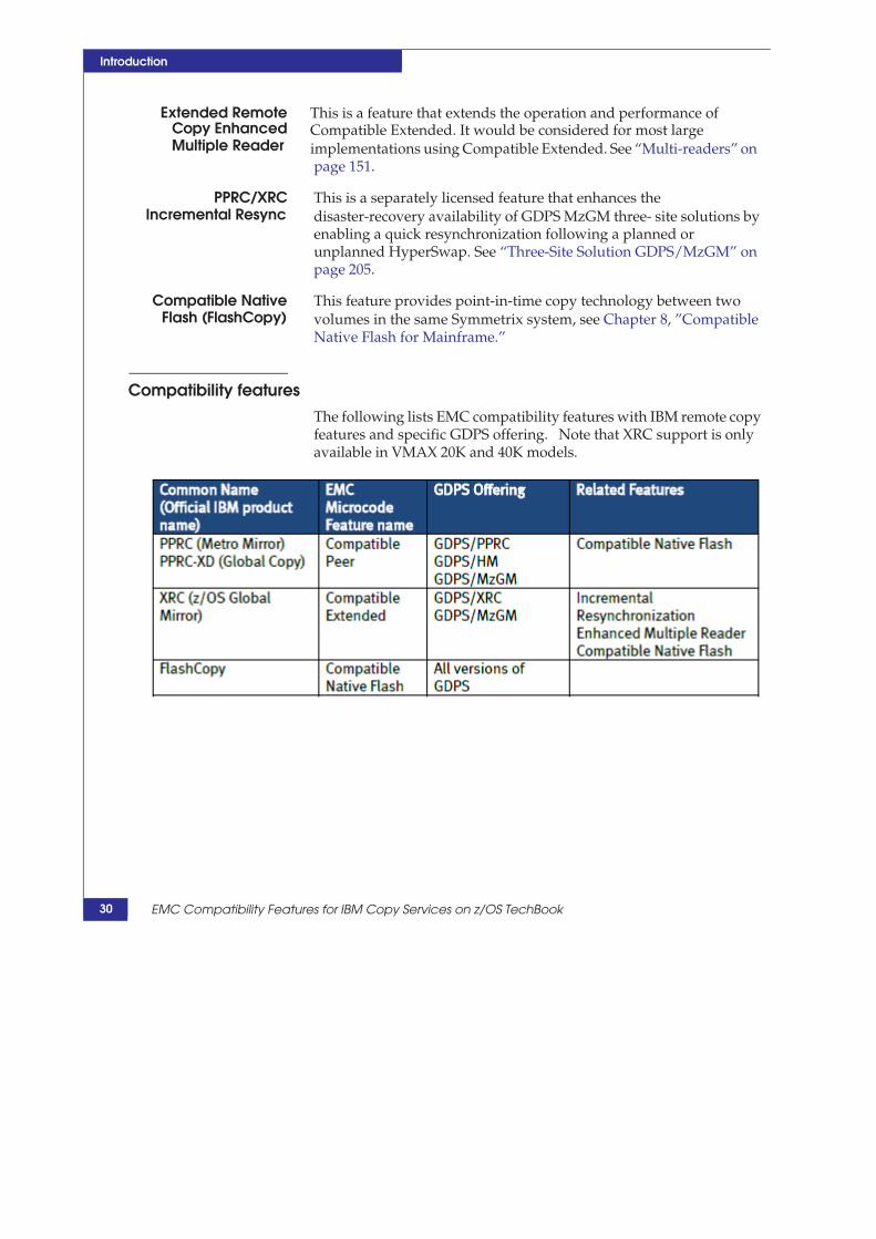
Compatibility features
The following lists EMC compatibility features with IBM remote copy features and specific GDPS offering. Note that XRC support is only available in VMAX 20K and 40K models.
30 EMC Compatibility Features for IBM Copy Services on z/OS TechBook

Introduction
Valid combinations for compatibility features Not all copy services features are implemented by the compatibility microcode features and that affects the combination table.
Table 1 Allowable Compatible Extended copy combinations
Valid combinations for compatibility features 31
If device is initially --->
Then it can also become: XRC Primary
XRC Secondary
PPRC Primary
PPRC Secondary
FlashCopy Source FlashCopy Target
XRC Primary
No, primary cannot be
in 2 sessions
Yes, but timestamps are
based on SDMwrites
Yes, this is
MzGM
configuration
No, but MzGM
creates shadow
sessions
Yes Yes
XRC Secondary
Yes, but timestamps are
based on SDM writes
No Yes No Yes No
PPRC Primary
Yes, this is
MzGM
configuration
Yes No No, cascaded PPRC
is not supported on
Symmetrix systems
Yes Yes
PPRC
Secondary
No No No, cascaded
PPRC is not
supported on
Symmetrix
systems
No Yes Yes
FlashCopy Source Yes Yes, this is GDPS/XRC
tertiary DASD
Yes, This is
Remote Pair
FlashCopy
Yes, This is Remote
Pair FlashCopy
Yes Yes, but not on the same
extents
FlashCopy Target No, you must XDELPAIR, FCESTABLISH XADDPAIR
No Yes, This is
Remote Pair
FlashCopy
Yes, This is Remote
Pair FlashCopy
Yes, but not on the same
extents
Yes, but not on the same
extents

Introduction
32 EMC Compatibility Features for IBM Copy Services on z/OS TechBook

2
GDPS Business
Continuity Solutions
This chapter provides the following information on GDPS business continuity solutions:
GDPS Overview 34 GDPS/PPRC ....................................................................................... 35 GDPS/HM .......................................................................................... 37 GDPS/XRC ......................................................................................... 38 GDPS/MzGM..................................................................................... 39 Unsupported GDPS architectures ................................................... 40 Common features of GDPS versions............................................... 41 Documentation ................................................................................... 45
GDPS Business Continuity Solutions
33

GDPS Business Continuity Solutions
GDPS overview GDPS is a suite of licensed software and implementation services offered by IBM to manage business continuity built on top of, and extending, the functionality of, native remote copy technology. There are several variants of GDPS (each individually licensed) that manage the different remote copy technologies (PPRC, XRC, FlashCopy, and Global Mirror) and their implementation over different topologies.
Technically, the GDPS offerings are not software products. Rather, they are licensed service offerings of IBM Global Services. However, support and software maintenance is delivered through normal IBM support channels.
GDPS implementations are solutions with many deliverables involving sysplex operations, sysplex definition, z/Series processors definition, LPAR definition, BCPii configuration, z/OS automation, inter-site connectivity, and DASD storage. They are multi-disciplinary implementations undertaken by a team of subject matter experts.
EMC’s role is confined directly to the Symmetrix system: Feature configuration, remote copy, connectivity, and those GDPS issues relevant to the implementation and operations of GDPS related to storage and remote copy.
GDPS is marketed by IBM Global Services as an “open” solution, meaning it can be implemented on any DASD subsystem that supports the remote copy features required by the version of GDPS.
34 EMC Compatibility Features for IBM Copy Services on z/OS TechBook

GDPS/PPRC
GDPS Business Continuity Solutions
GDPS/PPRC GDPS/PPRC is a business-continuity solution employing Compatible Peer (PPRC) for volume remote copy. GDPS/PPRC was the first variant of GDPS and established many of the architectural components and operations associated with GDPS.
GDPS/PPRC is one of the technologies that implement the foundational capabilities of FREEZE and HyperSwap.
FREEZE is a process (like an EMC CONGROUP trip) to preserve thedependent write consistency of the secondary DASD in order to facilitatethe restart of systems, applications, and workloads using the secondaryDASD. GDPS supports both planned and unplanned FREEZE events to facilitate recovery operations due to DASD, processor and site failures.FREEZE is an integral part of GDPS/PPRC, implemented through PPRC’sdirective CGROUP FREEZE operation.
HyperSwap is a process (like EMC AutoSwap™) to transparently swapdevice access between DASD units in order to eliminate DASD subsystemsas a single point of failure. GDPS supports both planned and unplanned HyperSwap to facilitate continuous operations due to DASD or site failures.HyperSwap also promotes continuous availability by nearly eliminatingsystem outage due to planned DASD outages. GDPS/PPRC may or maynot be implemented with a HyperSwap capability.
zHyperWrite is a performance solution for the DB2 active log and requires a Hyperswap environment. With zHyperwrite enabled DB2 active log writes are directed to the PPRC primary and PPRC secondary devices over the FICON channels required for Hyeprswap configuraitons. These writes do not flow across the PPRC links from primary to secondary as normal writes do in a PPRC environment. This result in much lower latency for the DB2 active log datasets. zHyperWrite is supported on VMAX3 and VMAX All Flash arrays running HyperMax OS only, and is not supported on VMAX 20K or 40K models.
GDPS/PPRC is tightly bound to its sysplex and seeks to be in the position of systems and storage control. Consequently, implementation and control of the remote copy operations and the systems in the sysplex require:
There is a one-to-one-to-one correspondence of GDPS/PPRC, the sysplex,and the GDPS/PPRC FREEZE GROUP. All z/OS systems in the sysplexmust be in the same GDPSplex1 and there is only one write dependency inthe sysplex.
1. The operational boundaries of GDPS/PPRC are significantly different thanGDDR. GDPS/PPRC is bound to the sysplex and all systems must be in a sysplex with GDPS K systems. All systems must be in the same sysplex. GDPS does not support non-sysplex systems (except for the very restrictive “foreign system” implementation). In contrast, GDDR is bound to the CONGROUP and can scale over multiple sysplexes and support sysplexed systems or non-sysplexed systems.
35

GDPS Business Continuity Solutions
Operations must avoid z/OS systems HMC management, as well as PPRC operations performed manually outside of GDPS/PPRC. System operations must use the GDPS facilities, or they must be confined to specific operational techniques (even Stand Alone Dump operations requires a GDPS-specific methodology to avoid interference with GDPS). SFM policies are also restricted in a GDPS implementation (system reset is GDPS’s decision alone).
PPRC DASD defined to GDPS must not be updated by systems outside the sysplex (or employ a “foreign system” architecture as outlined in the GPDS/PPRC Installation and Customization Guide). Data integrity of the FREEZE operation is dependent upon initial notification being presented to and processed by GDPS/PPRC.
Note: Even read access to PPRC remotely copied DASD is prohibited since OPEN for READ generates a write to update the VTOC.
Geographic distances are technically limited to sysplex connectivity and practically limited by application sensitivity1 to synchronous remote copy.
Depending on the implementation topology and availability expectations, GDPS/PPRC can resemble either GDDR CONGROUP or GDDR AutoSwap.
More information is provided in Chapter 3, ”EMC Compatible Peer (PPRC).”
1. Geographic distance imposes application restrictions for a number of technical reasons, not limited to remote copy and connectivity. Applications based on shared data in coupling facilities in multisite workloads can experience distance limitations more restrictive than synchronous remote copy and DASD connectivity.
36 EMC Compatibility Features for IBM Copy Services on z/OS TechBook
GDPS/HM
GDPS Business Continuity Solutions
GDPS/HM GDPS/HyperSwap Manager (GDPS/HM) is a related product to the more full-function GDPS/PPRC. GDPS/HM lacks the automation of GDPS/PPRC but provides the basic storage management and autonomic operations of FREEZE and HyperSwap.
Throughout this document references to GDPS/PPRC are applicable to GDPS/HM, except where noted.
37

GDPS Business Continuity Solutions
GDPS/XRC GDPS/XRC (Compatible Extended) is a business-continuity solution for disaster recovery based on XRC. XRC is a long-distance, asynchronous copy technology with limited performance impact to the production environment, and is only supported by the VMAX 20K and 40K models
GDPS/XRC requires an extensive deployment of z/OS systems and DASD at the recovery site. GDPS facilitates the operation of DASD recovery, z/Series system management and restart of production z/OS systems, applications and workload.
GDPS/XRC has some superficial architectural resemblance to GDDR SRDF/A in that it is an asynchronous replication solution, but XRC secondary volumes lack personality-swap capability. GDPS/XRC has no inherent reverse site switch capability following an unplanned outage.
GDPS/XRC was the second variant of GDPS introduced.
More information is provided in Chapter 5, ”Compatible Extended (XRC).”
38 EMC Compatibility Features for IBM Copy Services on z/OS TechBook

GDPS/MzGM
GDPS Business Continuity Solutions
GDPS/MzGM GDPS/MzGM is a three-site business-continuity solution combining high-availability and disaster recovery.
It is built upon a combination of GDPS/PPRC and GDPS/XRC. GDPS/PPRC manages operations between SITE1 and SITE2. GDPS/XRC manages operations between the current primary DASD SITE and SITE3.
GDPS/MzGM offers limited interoperability between the two component solutions. Interoperation between the GDPS/PPRC and GDPS/XRC is loosely coupled with few provisions for joint or coordinated operations.
More information is provided in “Three-Site Solution GDPS/MzGM” on page 207.
39

GDPS Business Continuity Solutions
Unsupported GDPS architectures EMC does not support Global Mirror-based solution GDPS/GM, nor its three-site implementation, GDPS/MGM.
40 EMC Compatibility Features for IBM Copy Services on z/OS TechBook

Common features of GDPS versions
GDPS Business Continuity Solutions
Common features of GDPS versions This section contains the following information for common features:
“Supported GDPS Releases” on page 41
“NetView operator” on page 41
“SCRIPT language with TAKEOVER, CONTROL, and BATCH scripts” on page 42
“GEOPARM and GEOXPARM storage policy definitions” on page 43
“Policy Data Base (PDB)” on page 43
“Sysplex” on page 44
“K systems” on page 44
Supported GDPS Releases
EMC has validated GDPS/PPRC, GDPS/XRC and GDPS/MzGM Releases 3.9 and 3.10.
NetView and system automation for z/OS components
Most GDPS functions run in the NetView address space and employ NetView and System Display Facility (SDF) panels for the operator interface, variable management, automated operations, DASD remote copy relationships, and inter system connectivity. GDPS is an application within NetView, which makes use of many of the imbedded technologies and automated operations capabilities of NetView.
GDPS employs System Automation for z/OS (also known as “SA”) for definition of the computing architecture, the business availability and recovery policies, host systems and coupling facility definitions, BCPii interface, recovery scripts, as well as maintenance of the interface to manage the definitions saved in the Production Data Base (PDB).
NetView operator Netview operator provides the human interface to GDPS (also available through a web interface).
41

GDPS Business Continuity Solutions
Top-down DASD remote copy panels with display, status, and manual operations
Site and remote copy status
Sysplex and systems management
Execution of control scripts
Activation of new PPRC definitions and GEOPLEX policy
Access to system automation’s SDF for dynamic monitoring and warning
SCRIPT language with TAKEOVER, CONTROL, and BATCH scripts
GDPS scripts1 consist of GDPS keywords that execute in the NetView Address space2. There are three kinds of scripts. The real distinction is when and how they can be invoked.
TAKEOVER scripts are run as a result of unplanned events, such as DASD failure, remote copy linkage failure, system failure, and site failure. Also known as unplanned actions, they cannot be invoked by manual operations (although there are known activities that can precipitate the failure symptoms and invoke the scripts). It is unlikely that EMC personnel would be involved with TAKEOVER script creation and or maintenance. TAKEOVER script names are generally reserved names that identify the failure or component.
CONTROL scripts are run by a NetView operator as a result of selecting the CONTROL script for execution.
BATCH scripts resemble CONTROL scripts, but can be invoked externally to the GDPS NetView operator.
GDPS scripts are unique to every GDPS implementation. The scripts are very specific to the individual product, with few examples of scripts that can be run in every environment.
This TechBook describes some operational aspects and documents the GDPS SCRIPT keywords. Documentation of creation,
1. GDPS scripts are significantly different in form and operation from GDDR scripts.
2. GDPS scripts are not REXX scripts, although there are keywords to invoke external REXX operations.
42 EMC Compatibility Features for IBM Copy Services on z/OS TechBook

Common features of GDPS versions
GDPS Business Continuity Solutions
management, and activation of the SCRIPTs, which requires using the SA for z/OS ISPF interface, is beyond the scope of this manual.
GEOPARM and GEOXPARM storage policy definitions
GEOPARM specifications establish the remote copy relationships between volumes (PPRC, XRC, and FlashCopy). PPRC GEOPARM establishes the expected linkage definitions and FREEZE GROUP definitions. XRC GEOXPARM defines to GDPS the expected SDM architecture. GEOPARM syntax is very dependent on the type of GDPS employed. Component specification, volume inclusion, and the definition of volume remote copy relationships establish the GDPS policy of the limit of operations and operational awareness.
Basically, the GEOPARM is a PDS with one active member allocated to the NetView domain1 (started task) running GDPS and edited through ISPF.
Alteration of GDPS’s mirroring definitions requires that you first alter the GEOPARM definitions, followed by validation and activation of the new GEOPARM.
Policy Data Base (PDB)
GEOPLEX policy is defined in SA for z/OS Policy Database. The operational policies of GDPS are established in the PDB, and the available settings are very dependent on the deployed version of GDPS. For instance, the FREEZE and SWAP policies of GDPS/PPRC are established in GDPS/PPRC PDB. Creation of the GDPS policy requires extensive customization of the standard sections of the PDB, as well as the addition of User ET pairs2. GDPS SCRIPTs also reside in the PDB as keyword pairs.
1. It is not uncommon to encounter environments with NetView domains dedicated to operations other than GDPS; only the GDPS NetView has a GEOPARM DD statement.
2. In form and structure, the PDB somewhat resembles the registry of Windows: Keywords and values.
43

GDPS Business Continuity Solutions
Sysplex
GDPS employs sysplex functionality and must be implemented as a sysplex. The one notable exception is GDPS/GM, which employs Global Mirroring, employs limited sysplex functionality, and is not supported by EMC’s compatibility features. GDPS/PPRC is an integral part of the production sysplex. GDPS/XRC runs a distinct recovery sysplex dedicated to running GDPS at the remote disaster recovery (DR) site.
K systems
A required feature of GDPS solutions are GDPS K1 z/OS systems (like GDDR C systems), which provide operational control. They should be designed with sufficient redundancy and separation to provide a point of control independent of DASD, processor, or site failures.
The GDPS K systems have specific Symmetrix implementation requirements. Principally, K system connectivity and K system isolation are important deliverables of EMC in a GDPS deployment.
1. GDPS was developed for VPC (now Euroclear Sweden) in StockholmSweden. Throughout the GDPS code, panel names, and global variables,there are legacy references to the initial site and its Swedish origin. The K,for KONTROL, is one of these legacies.
44 EMC Compatibility Features for IBM Copy Services on z/OS TechBook

Documentation
GDPS Business Continuity Solutions
Documentation This section provides documentation references.
Advanced Copy Services
The DFSMS Advanced Copy Services manual documents XRC, FlashCopy, PPRC operations, TSO commands, batch interfaces, diagnostic system commands, and assembler interfaces.
The EMC suite of compatible Advanced Copy Services is externally compliant with the documentation. EMC does not provide separate user guides for these features.
GDPS manuals
Generalized information regarding GDPS is available in GDPS Family – An Introduction to Concepts and Capabilities, which is available for download. Detailed implementation, customization, and operations material is available in the individual offering installation and customization guides, which are licensed IBM materials.
45

GDPS Business Continuity Solutions
46 EMC Compatibility Features for IBM Copy Services on z/OS TechBook
3
EMC Compatible Peer
(PPRC)
This chapter provides the following information on EMC Compatible Peer (PPRC):
PPRC overview................................................................................... 48 PPRC components.............................................................................. 49 SRDF/S operations and Compatible Peer...................................... 51 Supported and non-supported PPRC modes ................................ 52 PPRC operation .................................................................................. 53 Supported PPRC features ................................................................. 57 PPRC TSO commands....................................................................... 68 Other PPRC interfaces....................................................................... 69 Compatible Peer versus SRDF/S and Adaptive Copy ................. 70 FAST and Compatible Peer............................................................... 70 Compatible Peer limitations ............................................................. 70 Designing the solution for z/OS...................................................... 71 Conversion from SRDF/S to PPRC emulation .............................. 74
EMC Compatible Peer (PPRC)
47
EMC Compatible Peer (PPRC)
PPRC overview Compatible Peer (PPRC) is a volume-to-volume physical remote copy feature between different Symmetrix DASD subsystems. The EMC official name for this feature is Compatible Peer.
Externally, it is somewhat analogous to SRDF/S and AdaptiveCopy1, and there is some overlap in their operational modes.
Internally, Compatible Peer Remote Copy employs SRDF/S andAdaptive Copy2 operations and physical components in amanner of operation compatible with PPRC.
Because microcode operation shares some of the same components as SRDF, but is managed as PPRC, it is sometimes referred to as PPRC emulation.
EMC Compatible Peer is operationally equivalent to PPRC in a GDPS/PPRC implementation and most native PPRC implementations. When enabled with the compatible PPRC feature, EMC Symmetrix subsystems respond to PPRC CCWs, report errors as PPRC would, and can be managed through the external interfaces of TSO commands, ICKDSF directives, and the Advanced Copy Services API. This enables manual management or automated management (GDPS/PPRC or GDPS/HM) of PPRC operations on a Symmetrix system.
Compatible Peer’s volume pairs must be composed of EMC volumes. However, Symmetrix systems with Compatible Peer can be configured with other vendor DASD subsystems employing PPRC (side-by-side).
Even though Compatible Peer employs SRDF/S microcode operations and physical Symmetrix components, it is operated entirely by PPRC directives. Compatible Peer requires no EMC software for its definition and operation; in fact, the Symmetrix Control Facility address space (SCF) is counter-indicated in many GDPS/PPRC implementations.
1. Compatible Peer employs SRDF/S and Adaptive Copy operations andcomponents for remote copy operations. PPRC Primary Volumes andPPRC Secondary Volumes are SRDF/S R1 and R2 devices. It also uses theRDF linkage between a Symmetrix system and internally employed bySRDF Device Groups.
2. Operation of PPRC volumes by SRDF commands is not supported.
48 EMC Compatibility Features for IBM Copy Services on z/OS TechBook

PPRC components
EMC Compatible Peer (PPRC)
PPRC components Figure 1 illustrates the components of Compatible Peer implemented in a Symmetrix system.
Figure 1 PPRC components
Major PPRC components, as shown in Figure 1, include:
1. z/OS system PPRC links, devices, and remote copy are definedand managed from z/OS PPRC directives exclusively.
2. PRIMARY Symmetrix DASD subsystem.
a. Symmetrix Primary DASD serial number required for PPRCdirectives.
49

EMC Compatible Peer (PPRC)
b. Compatible Peer licensing.
c. PRIMARY DASD device addresses required for PPRCdirectives.
d. LCUs and SSIDs required for PPRC directives. The LCU andSSID have roles in the definition of the logical PPRC paths aswell as identifying the device-to-device remote copyrelationships.
e. SRDF GROUP (in the range 00-3F), defined in the Symmetrixconfiguration, is required for PPRC directives.
3. SECONDARY Symmetrix DASD subsystem.
a. Symmetrix Secondary DASD serial number required for PPRC directives.
b. Compatible Peer licensing.
c. SECONDARY DASD device addresses required for PPRCdirectives.
d. LCUs and SSIDs required for PPRC directives.
e. SRDF GROUP (in the range 00-3F), defined in the Symmetrixconfiguration, is required for PPRC directives (although theSRDF GROUP on the secondary VMAX is not required to bethe same as the SRDF GROUP on the primary VMAX, ittypically is).
4. FICON channel connectivity.
a. FICON channel connectivity to Primary DASD.
b. FICON channel connectivity to Secondary DASD.
5. SRDF linkage.
a. VMAX-to-VMAX physical links are used to define theLCU-to-LCU logical PATHs.
b. Physical RDF linkage (up to 8 shared physical RDF links perPPRC logical PATH between LCUs). The RDF ports can eitherbe Fibre Channel or GigE boards in the VMAX. When distancerequirements demand, Fibre Channel can employ SANswitches or FCIP converter. When using GigE portsconnectivity can use either IPV4 or IPV6 GigE network. If noswitch is employed the SRDF GROUP must be x’00’.
50 EMC Compatibility Features for IBM Copy Services on z/OS TechBook

SRDF/S operations and Compatible Peer
EMC Compatible Peer (PPRC)
SRDF/S operations and Compatible Peer
IMPORTANT
The Symmetrix configuration file and physical connectivity must be in agreement for Compatible Peer to emulate PPRC predictably, especially in GDPS/PPRC implementations.
Compatible Peer actually employs components and some microcode operations of SRDF/S. Compatible Peer’s PPRC PATHs, PPRC volume pairs, and CGROUPs operate exactly as PPRC PATHs, volume pairs, and CGROUPs.
The logical entity of SRDF/S GROUP name defined in the Symmetrix configuration file and the physical SRDF links are two components that are externalized in Compatible Peer definition and operation.
External manifestation of the SRDF/S GROUP name
The SRDF/S GROUP Name defined in the Symmetrix configuration file is represented in the PPRC PATH LINK definition between LCUs.
Typically, multiple SRDF/S GROUP Names are created in the Symmetrix configuration file. PPRC paths can all employ the same SRDF/S GROUP name or use different ones. With PPRC, preservation of the dependent writes is formed by some external entity using CGROUP FREEZE/RUN technology, such as GDPS/PPRC. Therefore, it is immaterial if different SRDF/S GROUP names are used or the same one.
Except for its role in the definition of PPRC PATHs, the SRDF/S GROUP Name is not involved in the formation of consistency or the external operation of Compatible Peer.
Symmetrix configuration file definition for RDF_Directors and the RDF_GROUPs should be in agreement with the intended LINK definitions in the PPRC CESTPATH definitions.
Because the underlying technology is SRDF, successful PPRC logical PATH management (through CESTPATH, CDELPATH, abd CGROUP FREEZE) depend upon agreement between the Symmetrix configuration file definition and CESTPATH definitions (and GDPS GEOPARM specification of the links between SSIDs in the LINKs Section).
51

EMC Compatible Peer (PPRC)
Supported and non-supported PPRC modes Compatible Peer supports two modes of PPRC operations:
Metro Mirror is a synchronous remote copy between volumepairs using PPRC PATHs over physical links. Additionally, it iscapable of forming dependent write consistency.
Global Copy, or PPRC XD, is a non-synchronous copy of changedtracks, without regard for consistency and without a CGROUP. Itis primarily used for copying data when dependent writeconsistency can be externally accomplished. Also, it is used byGDPS as a performance feature during resynchronizationoperations, when consistency is unattainable. PPRC XD is similarin operation to SRDF Adaptive Copy Disk Mode.
The following modes of PPRC operation are not supported by Compatible Peer:
Global Mirror (GM): A combination of PPRC XD, FlashCopy andremote control by a designed control DASD subsystem.
Metro Global Mirror (MGM): A cascaded configuration of MetroMirror and Global Mirror to create a three- site solution.
52 EMC Compatibility Features for IBM Copy Services on z/OS TechBook

PPRC operation
EMC Compatible Peer (PPRC)
PPRC operation The following is an overview of Compatible Peer implementation, management, operations, and device status (state transitions).
1. Identify pairs of Symmetrix DASD subsystems (primarySymmetrix and secondary Symmetrix system).
a. Define Compatible Peer options in the Symmetrixconfiguration.
b. Define SRDF group connectivity for SRDF/S.
2. Establish the PPRC logical paths between pairs of LCUs (SSIDs)designating multiple physical link address(es) with the TSOCOMMAND CESTPATH or through GDPS/PPRC GEOPARMdefinition.
a. Enable PPRC consistency group (CGROUP) for those LCUpairs whose volumes require consistency. CGROUP is aconsistency capability based on the paired volumes within apair of LCUs and their logical paths.
b. Logical paths are unidirectional, designating a primary LCUwith primary volumes and secondary LCU with secondaryvolumes.
3. Establish the remote copy sessions for pairs of z/OS volumes inSIMPLEX state (not in a remote copy relationship) and thesynchronization option in LCU pairs with the previously definedPPRC paths using the TSO COMMAND CESTPAIR (or throughGDPS/PPRC GEOPARM definition) and operations. Typically,the primary volume is online and secondary volume is offline.The primary volume remains online and available while thesecondary volume goes into an unavailable state.
a. Designate which volume pairs are PPRC synchronous.
b. Designate which volume pairs are PPRC eXtended Distance.
c. Depending on MODE specification, volume pairsautomatically begin initial COPY. Primary and secondaryvolumes are initially in PENDING state and transition toDUPLEX state as they complete initial copy.
4. Operation of a Remote Copy of writes.
a. When PPRC is in synchronous mode.
53

EMC Compatible Peer (PPRC)
– Write from the production system.– Write is accepted by primary Symmetrix.– Update is sent to secondary Symmetrix.– Acknowledgement from secondary Symmetrix to primary
Symmetrix.– Acknowledgement to system.
b. When PPRC is in XD mode.
– Write from production system.– Write is accepted by primary Symmetrix.– Acknowledgment to the production system.– Asynchronous update to secondary Symmetrix.– Acknowledgement from secondary Symmetrix to primary
Symmetrix.5. Remote Copy suspension: The primary and secondary volumes
are in suspended state with updates to the primary volumestracked in a bitmap (owed tracks). The volumes are in PRIMARYSUSPENDED state and SECONDARY SUSPENDED state.
a. Unplanned suspension with PPRC CGROUP occurs whenthere is a failure to remotely copy a write to the secondaryvolume (including a linkage failure). The ELB timer providesan opportunity for the external management system topreserve write dependency in the secondary volumes.
b. Unplanned suspension without PPRC CGROUP also occurswhen there is a failure to remotely copy a write to thesecondary volume. No provision is made to preserve writeconsistency in the secondary volumes.
c. Planned suspension with TSO COMMAND CSUSPEND orGDPS/PPRC operations.
6. PPRC resynchronization operation: volumes start in PRIMARYSUSPENDED and SECONDARY SUSPENDED.
a. Suspended volume pairs start resynchronization through theTSO COMMAND CESTPAIR with MODE(RESYNC) or theequivalent GDPS/PPRC operation.
b. Primary and secondary volumes return to DUPLEX statewhen resynchronization completes.
54 EMC Compatibility Features for IBM Copy Services on z/OS TechBook

PPRC operation
EMC Compatible Peer (PPRC)
7. PPRC FailOver/FailBack (FO/FB) is performed through theCESTPAIR TSO COMMAND CESTPAIR or GDPS/PPRCoperations.
a. FAILOVER is equivalent to an EMC SRDF half-swapoperation. Typically, it is employed after HyperSwapestablishing the previous secondary volumes are primaryvolumes (without necessarily defining the secondary volume)in anticipation of eventual resynchronization actions. Updatesare now tracked in the new primary volume’s bitmap,enabling a quick resynchronization after failover to secondaryDASD.
b. It is an enabling technology for HyperSwap.
c. FAILBACK re-establishes the original primary/secondaryrelationship. Changed tracks, recorded since FAILOVER arecopied to the specified secondary.
8. Remove volume remote copy session between volume pairs byusing the TSO COMMAND CDELPAIR or GDPS/PPRCoperations.
a. Primary and secondary volumes are returned to SIMPLEXstate.
9. Remove the logical Path and LCU to LCU pairing by using theTSO COMMAND CDELPATH or GDPS/PPRC operations.
10. Conversion of Metro Mirror to Global Copy.
Figure 2 on page 56 shows the abbreviated PPRC states.
55
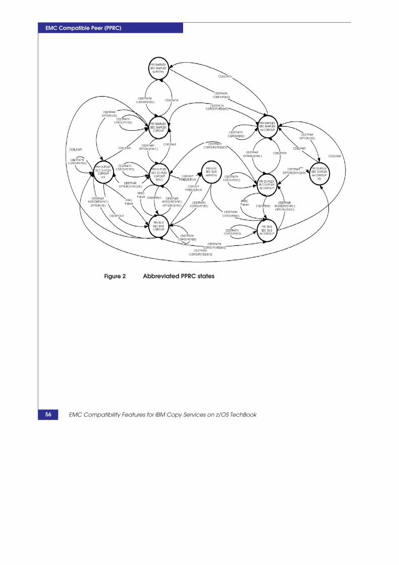
EMC Compatible Peer (PPRC)
Figure 2 Abbreviated PPRC states
56 EMC Compatibility Features for IBM Copy Services on z/OS TechBook

Supported PPRC features
EMC Compatible Peer (PPRC)
Supported PPRC features The following supported PPRC features are briefly discussed in this section:
“Metro Mirror and Global Copy” on page 57 “PPRC Consistency Group” on page 57 “CRIT(Y)” on page 59 “PPRC/FlashCopy Consistency Group Timeout” on page 59 “Volume pairs” on page 60 “PPRC pathing” on page 60 “Dependent write consistency” on page 63 “CGROUP FREEZE/RUN and the preservation of dependent write consistency” on page 64 “Failover Failback (FO/FB)” on page 64 “Link failure warning” on page 65 “MIDAW and PPRC” on page 65 “Query storage controller status” on page 65 “Summary event notification for PPRC suspends” on page 66 “Storage controller health message” on page 67 “CQUERY LINKINFO” on page 67
Metro Mirror and Global Copy
While it might seem convenient to think of the volume-to-volume relationship first, in actuality a more complete understanding of PPRC operations (as well as the management systems like GDPS) can be realized by first understanding the logical path definitions and physical RDF linkage used by PPRC.
By relating Logical Control Unit (LCU) pairs to the physical links and the consistency requirements, the logical pathing becomes the foundation of PPRC CGROUP consistency.
PPRC Consistency Group
PPRC consistency group is the basis by which dependent write consistency is formed by automation products, such as GDPS. It is based on the definition of the links between two LCUs, the physical SRDF links, the SRDF GROUP, and whether CGROUP is enabled for that LCU pairing and pathing or not when the PPRC PATH is established.
57

EMC Compatible Peer (PPRC)
A PPRC consistency group is on a LCU-to-LCU basis. It is explicitly enabled by the CGROUP parameter of the CESTPATH command, and its boundaries are limited to the volumes in a LCU pair.
The logical PATH between LCU pairs is established by the link addresses of the CESTPATH command and is essentially a logical representation of the physical links between Symmetrix subsystems using SRDF groups in the link address parameter of the CESTPATH command. The physical links are typically shared over many PPRC consistency groups (LCU pairs). The logical path between two LCU pairs can consist of up to 8 logical links between LCU pairs.
Typically, volumes and LCUs are established on a one-to-one basis. However, a primary LCU can be in more than one consistency group if the secondary volumes reside in multiple LCUs (fan out). Likewise, a secondary LCU can be in multiple consistency groups if the primary volumes are in multiple LCUs (fan in). A failure in one PPRC CGROUP does not imply failures in other PPRC consistency groups, even if the LCUs are in the same DASD subsystems.
PPRC remote copy failures (signaled by an interrupt from the CU) are issued only for the first write I/O that fails, then a long busy is raised for up to the duration of the PPRC Consistency Group Timer (ELB Timer). Subsequent writes to other volumes in that CGROUP will encounter long busy for the duration of the long busy delay.
ENF is raised and z/OS issues an IEA491E message.
If no action is taken during the LONG BUSY and the LONG BUSY “expires”, PPRC is suspended for the volume pairs in the consistency group and subsequent write I/Os do not result in LONG BUSY conditions.
The LONG BUSY enables automated operations to suspend all other PPRC remote copy relationships and preserve dependent write consistency.
Preservation of dependent write consistency during the LONG BUSY is one of the primary purposes of GDPS/PPRC. It is responsible for recognizing the first failure of remote copy volume pair in its policy, which might be the first indication of a disaster, and ensure dependent write consistency of the secondary DASD by propagating that suspension over all remaining remote copy pairs in its policy
58 EMC Compatibility Features for IBM Copy Services on z/OS TechBook

EMC Compatible Peer (PPRC)
while applications are waiting on the long busy indication. CGROUP only applies to PPRC synchronous. PPRC XD operation does not maintain consistency.
Note: An often-repeated misrepresentation of GDPS processing is to say that GDPS responds to the long busy, which it emphatically cannot recognize. GDPS responds to the external symptoms (ENF warning) and exploits the long busy during which it ensures the dependent write consistency of the secondary DASD.
CRIT(Y) CRIT(Y) is now an infrequently-employed technique for establishing data consistency and is actually somewhat incompatible with GDPS/PPRC. However, some customers still employ it as the means of achieving a near zero data loss policy.
Compatible Peer Supports CRIT(Y) specification and Symmetrix configuration file settings also support both CRIT(YES-ALL) and CRIT(YES-PATHS).
IBMDASDsubsystemsetting Symmetrix DASDsubsystemsetting Interpretation
CRIT(YES-ALL) CRIT HEAVY =YES Inhibits writes on any PPRC write failure, including secondary device failure
CRIT(YES-PATHS) CRIT HEAVY = NO Inhibits writes when all paths to a secondary volume are unavailable
PPRC/FlashCopy Consistency Group Timeout PPRC/FlashCopy Consistency Timer setting, also known as both LCU Long Busy and ELB Timer, is the duration that a device can present long busy after it reports a failure of a remote copy write in a CGROUP. It provides an opportunity of finite duration for automation systems to recognize the remote copy failure, propagate a CGROUP FREEZE across all PPRC CGROUPS, and, in doing so, preserve the dependent write consistency across all secondary volumes in multiple LCU pairs.
On Symmetrix systems, the ELB is set on the Symmetrix configuration IMPL initialization panel for CKD devices, PPRC/FlashCopy Consistency Group Timeout value.
Supported PPRC features 59
EMC Compatible Peer (PPRC)
Volume pairs
A Compatible Peer volume relationships on Symmetrix system consists of:
PPRC PRIMARY volume online to applications and can be reador written to. The device is actually an SRDF/S R1.
PPRC SECONDARY volume offline to applications. The z/OSvolume shares the same VOLSER as the primary volume. Thedevice is actually an SRDF/S R2.
Compatible Peer requires that the R1 and R2 devices are in different Symmetrix DASD Subsystems.
Compatible Peer requires that the devices are defined in the VMAX Configuration file Section VolMap as dynamic SRDF, setting DRX.
Volume-pair relationships are managed though the PPRC directives1
(typically, TSO commands):
CESTPAIR: Establishes remote copy between two volumes.
CDELPAIR: Deletes the PPRC session between two volumes andmakes both volumes simplex.
CSUSPEND: Stops active remote copy and makes the primaryvolume suspended, PRI(SUS), and the secondary volumesuspended, SEC(SUS).
CRECOVER: Deletes the PPRC session on the secondary deviceand makes the former secondary volume available for access byapplications (as a simplex volume).
PPRC pathing
Compatible Peer supports the physical RDF linkage to support PPRC logical pathing operations, definitions, management, error recovery and reporting.
A PPRC path is a logical relationship between LCU to LCU overspecific RDF links and a specified consistency (CGROUP).
The logical path is composed of at least one, and up to eight,physical RDF links.
1. In addition to TSO COMMANDS, there is also the ICKDSF statementsand assembler API. GDPS/PPRC employs the API.
60 EMC Compatibility Features for IBM Copy Services on z/OS TechBook

Supported PPRC features
EMC Compatible Peer (PPRC)
Physical links are typically shared by as many paths between LCU pairs as required.
Sending and receiving side director numbers are often the same position port and director but can be different.
Sending and receiving side SRDF Groups are often the same on the R1 and R2 Symmetrix DASD subsystems but may be different (i.e., GROUP 10 to GROUP 20).
Link definitions (linkaddr in the CESTPATH TSO command) are unique to Symmetrix systems. Symmetrix physical architecture differs from other vendor’s hardware offerings and definition of the links (linkaddr) will differ as well.
The formation of Symmetrix linkaddr is described in Appendix A, “PPRC PATHing and Linkage Address.”
The formation of dependent write consistency over multiple LCU pairs spanning multiple DASD subsystems is dependent on the timely interruption of the logical paths by some external management such as GDPS. EMC Consistency Group software, such as SCF, does not form PPRC CGROUP consistency and is not required.
Transparent definition and management through the existing PPRC TSO commands, with the exception of the before-mentioned linkaddr definitions, unique to Symmetrix connectivity.
Warning and failure reporting consistent with PPRC operations and compliant with GDPS/PPRC.
There is no mechanism to add or delete single links in a PPRC path. Issuing subsequent CESTPATHs for the same LCU pairs constitutes a complete replacement for all links between the LCUs. As previously mentioned, because the underlying remote copy technology is SRDF/S, Compatible Peer, PATH management operates most consistently with PPRC operations when the Symmetrix configuration file definitions of RDF_Director and RDF_GROUPs are in agreement with the PPRC CESTPATH definitions.
Logical paths are managed through the following PPRC command directives (TSO Command names):
CESTPATH creates or replaces all existing linkage between LCU pairs.
CDELPATH deletes all the existing linkage between LCU pairs.
61

EMC Compatible Peer (PPRC)
CGROUP FREEZE deletes all existing linkage between LCU pairs and suspends all volume pairs.
Path specifications unique to EMC
In addition to the linkaddr physical differences related to the PPRC PATH specification, there is another difference, unrelated to remote copy operations, that effects Symmetrix path definitions. Recent IBM DASD Subsystems support World Wide Node Name (WWN) reference of their Fibre Channel adapter number instead of by serial number. The change in IBM connectivity (physical ESCON to FCP) corresponded to WWNN support.
SRDF ports (FCP or GigE) on Symmetrix systems do not use WWNN identification and definitions of the PPRC logical paths. Instead, they must employ serial number format. This difference is also reflected in the definition of the paths in the GDPS GEOPARM. See “GEOPARM specifications unique to Symmetrix systems” on page 104 for further discussion on pathing definition under GDPS.
TSO CESTPATH examples
Establish pathing between two LCUs without a consistency group
CESTPATH DEVN(x’nnnn’) SUBCHSET(0) PRIM(x’ssid’ serialno x’lss’) SEC(x’ssid’
serialno x’lss’) LINK(x’linkaddr’,…,x’linkaddr’) CGROUP(NO)
nnnn is 4 character hex device address in the primary LCU
ssid identifies the Service Set Identifier (SSID), uses the ssid and serial number specification instead of WWNN specification.
serialno is the serial number of the Symmetrix system.
lss is the LCU.
linkaddr 1 to 8 RDF links in PPRC format. For a description of linkaddr formation, see Appendix A, “PPRC PATHing and Linkage Address”.
Establish pathing between two LCU and establish a consistency group CESTPATH DEVN(x’nnnn’) SUBCHSET(0) PRIM(x’ssid’ serialno x’lss’) SEC(x’ssid’
serialno x’lss’) LINK(x’linkaddr’,…,x’linkaddr’) CGROUP(YES)
Remove pathing between two LCUs CDELPATH DEVN(x’nnnn’) SUBCHSET(0) PRIM(x’ssid’ serialno x’lss’) SEC(x’ssid’ serialno x’lss’)
62 EMC Compatibility Features for IBM Copy Services on z/OS TechBook

Supported PPRC features
EMC Compatible Peer (PPRC)
Freeze PPRC between two LCUs CGROUP FREEZE DEVN(x’nnnn’) SUBCHSET(0) PRIM(x’ssid’ serialno x’lss’) SEC(x’ssid’
serialno x’lss’)
Resume I/O after a FREEZE CGROUP RUN DEVN(x’nnnn’) SUBCHSET(0) PRIM(x’ssid’ serialno x’lss’) SEC(x’ssid’ serialno x’lss’)
Recommendations on cabling and director/port selection
Keep the SRDF FCP linkage simple. Most large-scale remote copy solutions feature symmetrical configurations of the local and remote Symmetrix DASD subsystems.
Dependent write consistency
A key feature of any meaningful computing is the concept of dependent writes. Applications perform writes in a known order by waiting for a write to complete before initiating a second write. Critical to the restart of most database systems is the ability of the application to determine the state of transactions and back out of incomplete changes. Regardless of whether restart is attempted against the PPRC primary DASD or the recovered PPRC secondary DASD, successful restart of most applications depends upon the preservation of dependent writes in that set of DASD subsystems. There can be no “missing” writes.
Large-scale remote copy, that is, remote copy that involves many thousands of volumes in multiple DASD subsystems connected by multiple physical links, introduces susceptibility in disaster recovery scenarios when a rolling disaster suspends remote copy operations at different times. Allowing the uncoordinated and incomplete remote copy suspension in the secondary DASD subsystems has the very real potential for creating a state where some but not all dependent writes have been mirrored. This can result in data base management systems that cannot RESTART when they detect the loss of dependent write consistency. Or worse, there may be a loss of data integrity that is undetectable by the applications.
From the perspective of applications, the choice is stark:
Application restart: Resumption of operations that resemble a restart after a power loss; or
Application recovery: Resumption of operations that depend upon restoration of backups and application of logs.
63
EMC Compatible Peer (PPRC)
An application restart takes place in a known period of time, typically measured in tens of minutes. However, an application recovery is a nearly open-ended proposition that, depending on the backups, logs, and applications, can take days.
It is for this reason that EMC developed SCF CONGROUP, and IBM developed GDPS/PPRC FREEZE.
CGROUP FREEZE/RUN and the preservation of dependent write consistency
The PPRC directive CGROUP (TSO command or API) is the mechanism used by automation systems to preserve dependent write consistency in the secondary PPRC DASD. An overview of consistency group operations follows:
1. Create logical paths between LCU with CESTPATH and establish a PPRC consistency group using CGROUP(Y) (or use GDPS/GEOPARM GEOPARM).
2. Create volume pairs. Once copy operations complete, the volumes pairs are in duplex state.
3. When primary Symmetrix Compatible Peer detects a remote copy failure of a write I/O to a PPRC SECONDARY volume it interrupts the z/OS host that issued the write, and then puts the primary PPRC volume in long busy for the duration of the ELB timer.
4. Subsequent writes to other volumes in same LCU pair CGROUP simply WAIT. The primary Compatible Peer makes no effort to re-notify the host of any subsequent remote copy failures.
5. An automation system (such as GDPS/PPRC) detects the failure, and while applications are waiting, the automation system must preserve all dependent write consistency in the secondary DASD by using CGROUP FREEZE to delete all PPRC PATHS and suspend all PPRC pairs in LCU pairs with CGROUP(Y).
6. Once all CGROUP FREEZEs complete, a CGROUP(RUN) can be issued by the automation system to enable writes to the primary DASD.
Failover Failback (FO/FB) Failover/Failback is a PPRC management feature to improve resynchronization performance, reduce exposure to failures during
64 EMC Compatibility Features for IBM Copy Services on z/OS TechBook

Supported PPRC features
EMC Compatible Peer (PPRC)
resynchronization, and simplify failover and failback during site swaps. Without FO/FB capability, PPRC must completely resynchronize volumes after an unplanned DASD site swap.
Conceptually, FO/FB operates much like an SRDF half swap. It creates a bit table of changed tracks on a newly enabled PPRC primary device that had previously been a PPRC secondary device. Failover is established by the CESTPAIR command using the ACTION parameter. EMC Compatible Peer feature supports FO/FB.
GDPS/PPRC exploits FO/FB to speed resynchronization after HyperSwap and FREEZE.
Link failure warning
In Compatible PPRC operations, RDF Link failures generate message IEA498I to indicate that a PPRC link status has changed. This feature is implemented on Symmetrix systems for GDPS/PPRC support.
See discussion in Chapter 4, ”GDPS/PPRC,” on the warning status related to trapping the IEA498I message.
MIDAW and PPRC
The primary and secondary volumes in a PPRC pair must both have the same MIDAW status when HyperSwap is deployed.
Query storage controller status
This feature enables automation (such as GDPS) to query the status of secondary DASD subsystems and potentially reduce false-freezes events. VMAX DASD subsystems are recognized by GDPS/PPRC as Reduced False Freeze-capable when QSCS is implemented on all VMAX DASD subsystems.
65

EMC Compatible Peer (PPRC)
Comparison of IBM and EMC query storage controller status
During FREEZE operation, while production systems’ writes are waiting on the ELB timer (prevented from updating primary or secondary PPRC DASD in FREEZE GROUPs) automation systems can employ the Query Storage Controller Status feature as the mechanism to determine the cause of the FREEZE.
Table 2 Query DASD storage controller status comparison
PPRC Remote Copy failure IBMDS8700 DS8800 Microcode response
Symmetrix Compatible Peer Microcode response
Device Is Fenced Applies Does not apply to Symmetrix system
Pinned Data Exists for the Device Applies Does not apply to Symmetrix system
Device is in Long Busy Applies Applies
Write Inhibited Applies Applies
Device exists on an Array that is rebuilding Applies Does not apply to Symmetrix system
Data Exists inthe failed non-volatile storage for this device Applies Does not apply to Symmetrix system
Rank State is Inaccessible Applies Does not apply to Symmetrix system
Rank State is Offline Applies Does not apply to Symmetrix system
Other Symmetrix and SRDF/S failures Does not apply to IBM Applies
Summary event notification for PPRC suspends
This is a feature of the DS8K Synergy Package 2. It is a combination of z/OS 1.13 and microcode that affects operator notification when volume paris suspend. When PPRCSUM is enabled, the DASD subsystem issues only a single summary message on an LCU basis, instead of issuing a state change interrupt and message for every device pair suspended.
Summary Event Notification is not supported by Compatible Peer
66 EMC Compatibility Features for IBM Copy Services on z/OS TechBook

Supported PPRC features
EMC Compatible Peer (PPRC)
Storage controller health message
This is a feature of the DS8K Synergy Package 2. IBM DASD uses it to notify the operating system of moderate and acute alerts. EMC DASD subsystems do not issue Storage Controller Health Messages. GDPS/PPRC's ENQ listener routine recognizes only two acute alerts, “pinned non-retryable error on a device or data loss occurred” as potential HyperSwap triggers. EMC believes that there are no analogous failure scenarios on VMAX arrays and support is unwarranted at this time.
CQUERY LINKINFO
This is a feature of DFSMS 1.13. As of this writing, feature support is under review.
67

des a brief description of the native TSO PPRC
mmands
Command Purpose Primary Volume
Secondary Volume
CDELPAIR Removes the volume pair fromPPRC Y Y
CDELPATH Deletes the PPRC Path froma primary LCU to a secondary LCU.
Y N
CESTPAIR Establishes a PPRC relationship, or resynchronize two volumes. Also used in conjunction with HyperSwap or FO/FB to performthe equivalent of a half swap. Establishes synchronous or XDrelationship.
Y Yfor Failover; Otherwise, N
CESTPATH Establishes a PPRC path between two LCUs or replaces the existing linkage definitions between two LCUs, optionally establishes CGROUPfor all volume pairs in the LCU-to-LCU pairing. Note that subsequent CESTPATH commands replace all existing pathing information between two LCUs.
Y N
CGROUP For FREEZEoption, removesthe path between two LCUs and suspends all PPRC relationships. The RUN option resumes applications suspended because of CGROUPFREEZE or CGROUPlong busy.
Y N
CQUERY Queries the status of primary or secondary volumes, as well as the pathing status.
Y Y
CRECOVER Alters the status of a secondary volume fromsuspended to simplex, volumecan be put online toa systemand used. Once a volume is CRECOVERed in order to resume remote copy operations it must be entirely recopied.
N Y
CSUSPEND Suspends the remote copy relationship of a volume pair, but updates are tracked, and remote copy between the primary and secondary volumes can be resumed.
Y Y
Services on z/OS TechBook
EMC Compatible Peer (PPRC)
PPRC TSO commands Table 3 provicommands.
Table 3 PPRC TSO co
68 EMC Compatibility Features for IBM Copy

Other PPRC interfaces
EMC Compatible Peer (PPRC)
Other PPRC interfaces The assembler interface ANTRQST is supported, as well as the TSO and ICKDSF interfaces.
GDPS DASD Mirroring Panel and DASD SCRIPT commands are completely supported by Compatible Peer. Compatible Peer volumes cannot be managed by SRDF commands.
In addition, EMC services actions must consider the presence of PPRC mode volumes.
The ICKDSF PPRCOPY commands are also supported.
69
EMC Compatible Peer (PPRC)
Compatible Peer versus SRDF/S and Adaptive Copy The technology of dependent write consistency preservation in the secondary DASD subsystems is a principle difference between Compatible Peer and its underlying technology, SRDF/S.
Native SRDF/S’s consistency within a Symmetrix system is based on SRDF Device and propagation of dependent write consistency over multiple Symmetrix systems and devices requires EMC CONGROUP software.
Compatible Peer dependent write consistency is based on PPRC CGROUP on an LCU-to-LCU basis. Preservation of dependent write consistency requires an external automation system, such as GDPS/PPRC.
FAST and Compatible Peer EMC FAST™ statistics are transmitted by Compatible Peer from the Primary DASD subsystem to the Secondary DASD subsystem. Unlike other PPRC implementations, Compatible Peer ensures that the secondary DASD Tiering is representative of the primary DASD subsystem. Consequently, I/O performance is not adversely affected through tiering misalignment on VMAX arrays.
Compatible Peer limitations Consider the following significant limitations:
Compatible Peer does not support PPRC “loop back”configurations, which link a Symmetrix DASD subsystem’s SRDFback to itself, as well as defined PPRC paths from LCUs back toother LCUs in the same Symmetrix system. Compatible Peer, likeits underlying SRDF technology, only allows remote copydefinitions (paths and volume pairs) between LCUs in differentSymmetrix systems.
Compatible Peer does not support PPRC open systems FBAdevices. It only supports PPRC directives from FICONconnectivity.
Compatible Peer does not support cascaded PPRC.
70 EMC Compatibility Features for IBM Copy Services on z/OS TechBook

EMC Compatible Peer (PPRC)
Designing the solution for z/OS This section describes the actions required for enabling Compatible Peer on a Symmetrix DASD subsystem and contains the following information:
“PPRC Symmetrix system configuration specifications” on page 71
“Volume Map PARMs” on page 72
“PPRC connectivity” on page 72
“Security authorization” on page 73
“EMC PPRC link definition” on page 73
PPRC Symmetrix system configuration specifications
Symmetrix configuration settings, shown in Table 4, are set by EMC Customer Service.
Table 4 Symmetrix configuration settings for PPRC compatibility (page 1 of 2)
Name Value Description
CKD->impl_fix_part->Enable Page data set MODE
YES | NO If page data sets’ volumes areremotecopied, then set to YES. When HyperSwap is implemented, page data sets must be mirrored. Check GDPS GEOPLEX OPTIONS PRIMARYFAILURE or FREEZE policy for a SWAP setting.
CKD->impl_fix_part->Enable Cache Fast Write YES | NO HyperSwap requires that writes be hardened to primary DASDand remotecopied tosecondary DASD. Set to NO for HyperSwap implementations. Check GDPS GEOPLEX OPTIONSPRIMARYFAILURE or FREEZE policy for SWAPsetting.
CKD->impl_fix_part->PPRC Crit Heavy YES | NO Validate setting with customer. Unused in most GDPS/PPRC deployments.
CKD->impl_fix_part->PPRC/FlashCopy Consistency Grouping
YES | NO Enables PPRC consistency grouping for CESTPATH. Required for GDPS/PPRC implementations.
Designing the solution for z/OS 71

EMC Compatible Peer (PPRC)
Table 4 Symmetrix configuration settings for PPRC compatibility (page 2 of 2)
Volume Map PARMs
Set SRDF attributes to DRX to enable a volume to be either an R1 or R2, which is required for GDPS/PPRC.
PPRC connectivity
Compatible Peer employs the same physical linkage as SRDF/S, and it can be implemented with the same FCP linkage used for SRDF/S. However, to form dependent write consistency, PPRC requires automation technology, such as GDPS/PPRC. GDPS, which is dependent upon a z/OS sysplex at both the primary and secondary sites, introduces network connectivity issues and requirements that tend to dominate the network provisioning. In addition, high-availability deployments employing HyperSwap require cross-site FICON connectivity compatible with system and applications operations, which also dominates decisions regarding the network provisioning.
72 EMC Compatibility Features for IBM Copy Services on z/OS TechBook
Name Value Description
CKD->impl_fix_part->PPRC/FlashCopy Consistency grouping timer
0:65535 seconds AKA ELB, default of 0 results in a value of 120 seconds whichistypical of many GDPS/PPRCimplementations. A nonzero value specifies duration inseconds. Too lowof a value can result in corruption of the dependent write consistency onthesecondary DASDif GDPSis unableto complete all CGROUPFREEZE and CGROUPRUN prior to the expiration of the timer.
Some GDPS/PPRC implementations require maximum ELBsettings. To avoid data corruption, reviewthe implementation topology and intended availability requirements against the current GDPS/PPRC Installation and Customization Guide for the proper ELB settings.
The Consistency Timer value applies to all LCUs in the Symmetrix system.
RDF->impl_fix_part->RDF Mode SRDF Set to SRDF for Compatible Peer
RDF->Switched RDF YES | NO Set toYES

Designing the solution for z/OS
EMC Compatible Peer (PPRC)
These considerations dictate a physical network not always typical of simple PPRC and SRDF/S, but they are required of most solutions employing Symmetrix Compatible Peer (similar performance considerations exist for many GDDR deployments). See “GDPS/PPRC networking topologies” on page 120 for a discussion of networking topologies typical of a GDPS/PPRC deployment.
Any proposed Compatible Peer RDF linkage and cross-site FICON linkages must be consistent with the GDPS/PPRC network deployment, which more often than not, employs DWDM infrastructure and redundant dark-fiber implementation.
Security authorization
When implementing Compatible Peer, refer to the IBM Advanced Copy Services manual for direction on securing PPRC TSO commands.
EMC PPRC link definition
Refer to Appendix A, “PPRC PATHing and Linkage Address,” for examples of defining the LINKADDRESS parameter in the CESTPATH command to define PPRC links on Symmetrix systems.
73

EMC Compatible Peer (PPRC)
Conversion from SRDF/S to PPRC emulation Compatible Peer employs SRDF/S components and operations. It is feasible to convert from SRDF/S to Compatible Peer, as well as the reverse, without initially copying all the data. These procedures are intended to be performed as attended operations (by EMC), as planned actions without updates from production.
74 EMC Compatibility Features for IBM Copy Services on z/OS TechBook
4
GDPS/PPRC
This chapter provides the following information on GDPS/PPRC:
GDPS/PPRC and GDPS/HyperSwap Manager (GDPS/HM) ... 76 GDPS/PPRC components ..................................................................77 EMC DASD Support Matrix for GDPS/PPRC ................................81 GDPS/PPRC storage management functions .................................82 GEOPARM .................................................................................................. 83 Autonomic policies and GEOPLEX ..................................................84 FREEZE autonomic operation ...........................................................88 Sharing VMAX DASD subsystems ...................................................90 HyperSwap autonomic operations (unplanned HyperSwap) ......91 GDPS/PPRC DASD subsystem components ..................................99 GDPS/PPRC GEOPARM specification .......................................... 102 FlashCopy with GDPS/PPRC ......................................................... 108 Symmetrix systems compatible feature licensing in
GDPS/PPRC 107 CFHINT considerations ................................................................... 112 GDPS/PPRC operations .................................................................. 113 GDPS/PPRC DASD BATCH SCRIPT VPCEXIT2 ........................ 115 Locating PPRC error messages within GDPS/PPRC ................... 116 GDPS/PPRC employment of alternate subchannel support
with Symmetrix systems .................................................................. 115 Validating GDPS autonomic operations ........................................ 118 GDPS/PPRC networking topologies ............................................. 120
GDPS/PPRC 75
GDPS/PPRC
GDPS/PPRC and GDPS/HyperSwap Manager (GDPS/HM) GDPS/PPRC is a business-continuity solution based on sysplex technology and PPRC remote copy. GDPS/PPRC is implemented in a variety of deployments to tailor different systems and storage availability, from near continuous availability with HyperSwap to simple disaster recovery deployments, using only CGROUP FREEZE and restart of workloads. GDPS/PPRC, like EMC GDDR, provides not only storage availability but systems availability and automation as well.
GDPS/PPRC is not IBM’s only offering with some of these functionalities. The IBM TotalStorage Productivity Center for Replication for System z product provides some of the same functionality as GDPS/PPRC and GDPS/HM.
GDPS/PPRC operations are dependent upon sysplex connectivity between both sites. New implementations require sysplex connectivity between all systems and sites as a single sysplex. It is sometimes suggested that GDPS is required for multi-site sysplex. However, in actuality, GDPS requires multi-site sysplex topology and connectivity as one of its pre-requisite technologies1.
GDPS/PPRC is the responsible agent for dependent write consistency. Compatible PPRC in a GDPS/PPRC requires no EMC storage management or availability components in ResourcePak for the management of the underlying SRDF operations. The only required management resources is GDPS/PPRC. Even TSO PPRC commands must be employed with caution to as not to instigate unintended GDPS/PPRC autonomic operations.
1. The exception is the rarely deployed Business Continuance architecture of GDPS/PPRC, which calls for an active K systems at the primary site, andallows for extremely limited cross-site connectivity, and no multi-sitesysplex connectivity. Deployment further requires maintaining a K system image at the disaster-recovery site that is NOT part of the productionGDPS sysplex. The restart of operations requires a manual re-IPL of theGDPS/K system, followed by CRECOVER operations of the PPRCsecondary DASD, and GDPS assisted re-IPL of the production systems,and restart of workload.
76 EMC Compatibility Features for IBM Copy Services on z/OS TechBook

GDPS/PPRC components
GDPS/PPRC
GDPS/PPRC components Figure 3 illustrates a GDPS/PPRC topology and common components.
Figure 3 GDPS/PPRC components
77

GDPS/PPRC
Major GDPS/PPRC components, shown in Figure 3 on page 79, are listed below. Not all of these are germane to EMC’s role and responsibilities in a GDPS/PPRC implementation, but have been included:
1. SITE1: The inventory of physical resources defined as residing atSITE1, including DASD, systems, processors (assumed to be thelocation of primary DASD most of the time).
2. SITE2: The inventory of physical resources defined as residing atSITE2.
3. GDPS K Master K system: At least one GDPS/PPRC K z/OSsystem is required, typically architected at SITE2. GDPS runs onall z/OS systems, but the GDPS/PPRC K systems are speciallydesigned systems. They must be members in the sysplex (6). Theyrequire access to all the SITE1 DASD subsystems (7) and SITE2DASD subsystems (8). They require utility devices (7a, 7b) formanagement of PPRC. However, the K systems cannot use any ofthe mirrored DASD (7c, 8C). They must have connectivity anduse the sysplex data sets (7d, 8d). They must use their ownisolated local DASD (7b, 8b), which cannot be remote copyvolume.
4. Other GDPS/PPRC K systems: Two GDPS/PPRC systems arerecommended (especially if HyperSwap policy is intended in thearchitecture).
5. Production systems: Usually the production systems are local toone site, but architectures with higher levels of availability do notrestrict application systems to one site.
a. z/OS systems in the sysplex.
b. Coupling facilities used in the sysplex.
6. A sysplex: A GDPS/PPRC instance must reside in a sysplex, anda GDPS instance can only manage one-time consistency. Multiplesysplexes require multiple instances of GDPS/PPRC. Typically,sysplex connectivity requires DWDMs and dark-fiber. Sysplexprotocols require qualified DWDMs and cards.
7. SITE1 DASD: Traditionally the primary DASD. However,HyperSwap implementations, especially implementations at zerodistance, enables an agnostic approach to the situational localityof “primary” PPRC DASD.
78 EMC Compatibility Features for IBM Copy Services on z/OS TechBook

GDPS/PPRC components
GDPS/PPRC
a. GDPS/PPRC utility volumes for PPRC operations by Ksystems. In the GEOPARM these devices are identified in theNONSHARE section, NONSHARE keywords.
b. GDPS local DASD: The DASD used by the GDPS K system;SIMPLEX (not remote copied); not subject to a PPRC FREEZE;and must not be used by other systems; and typically thevolumes for each K system are confined to a dedicated LCUwithout any PPRC logical paths. These devices are notexplicitly identified in GEOPARM.
c. PPRC primary DASD: In some architecture always thePRIMARY PPRC DASD, but architectures with continuousavailability do not require the association of primary DASD toa physical site (two logical sites within a physical site). In aHyperSwap implementation, both system and applicationaccess to this set of DASD is swapped with 8c. These devicesare identified in the GEOPARM, section MIRROR PPRCkeyword parameter s1dev.
d. Simplex DASD: For a variety of uses depending on GDPSarchitecture and availability requirements, but also the sysplexdata sets. With architectures that do not involve HyperSwapthis could be infrastructure volumes required for restart ofsystems, such as page data sets and volumes containingtemporary data sets. These devices are not identified in theGEOPARM.
e. Optional GDPS/PPRC managed FlashCopy DASD at SITE1:Principally provisioned for two purposes: 1) established aFlashCopy relationship from 7c to 7e prior to re-synchronizing from 8c to 7c, during which time 7c’s dependent writeconsistency is corrupt, 2) DR test image. GDPS/PPRC onlysupports FlashCopy interface (Compatible Native Flash). Inthe GEOPARM FlashCopy targets are identified in theMIRROR section, PPRC keyword parameters "s1fdev".FlashCopy target devices are typically defined in their ownLCUs distinct from their FlashCopy source devices. Generally,these FlashCopy target LCUs have the same offset addressingas their source LCUs.
f. The primary PPRC LCU: Part of the LCU pair identified by thecreation of a CGROUP. It contains PPRC primary volumes 7cand is further augmented by the provisioning of aGDPS/PPRC utility volume 7a.
79

GDPS/PPRC
8. SITE2 DASD: Traditionally the secondary DASD.
a. Utility devices. Like 7a, these devices are identified in theNONSHARE section of the GEOPARM keyword nonshare.
b. GDPS/PPRC local DASD. Typically the GDPS/PPRC KMaster System’s local DASD, like 7b, these devices are notexplicitly identified by the GEOPARM.
c. PPRC secondary DASD. Like 7c these devices are identified bythe PPRC statements in the GEOPARM. They are specified inthe GEOPARM mirror section, keyword PPRC parameters2dev.
d. Simplex DASD.
e. Optional GDPS/PPRC managed FlashCopy DASD at SITE2:Has similar provisional considerations as 7e. They areidentified in the MIRROR section, PPRC keyword'sparameters "s1fdev". As is the case with the primaryFlashCopy targets (7e), these too are generally confined totheir own LCU.
f. The secondary PPRC LCU: Part of the LCU pair identified bythe creation of a CGROUP. It contains PPRC secondaryvolumes 8c and is further augmented by the provisioning of aGDPS/PPRC utility volume 8a.
9. cross-site DASD connectivity: Complexity and bandwidthdepends on the solution’s implementation and intended systemand DASD availability. Non-HyperSwap solutions requiremodest cross-site connectivity (only the K Master system needsaccess to the SITE1 DASD from SITE2). Because HyperSwapassumes that operations must continue after a HyperSwap, thoseimplementations’ cross-site connectivity must have theperformance and redundancy of local-site connectivity.
10. PPRC linkage: Symmetrix RDF links used to form PPRC paths.Identified in the GEOPARM SITE1 and SITE2 statements.
11. BCPii: Interfaces and components, HMCs, SEs, TCP/IPconnectivity.
12. Spare CEC and LPAR: Resources required and capacity onstandby.
80 EMC Compatibility Features for IBM Copy Services on z/OS TechBook

EMC DASD Support Matrix for GDPS/PPRC
GDPS/PPRC
EMC DASD Support Matrix for GDPS/PPRC See Appendix D, “GDPS/PPRC Support Matrix,” for the complete VMAX array, base Enginuity, Compatible Peer, and Compatible Native Flash matrix.
81

GDPS/PPRC
GDPS/PPRC storage management functions The following are the basic operations, operational goals, and how GDPS/PPRC accomplishes them.
GDPS/PPRC FREEZE and HyperSwap are features of automation technologies. They are not native operations of the DASD subsystem, but they exploit the CGROUP FREEZE feature of PPRC capable controllers.
PPRC path management definition: starting and stopping of paths and CGROUP FREEZE.
PPRC device management, pair definitions, operations, starting and suspending PPRC through panel operations, script operations, and autonomic operations .
Availability through planned and unplanned HyperSwap operations.
Remote Copy status monitoring. GDPS/PPRC has monitoring functions to constantly validate many aspects of the solution’s integrity.
FlashCopy management to create DR copies, as well as ensure a recoverable point-in-time copy during resynchronization.
82 EMC Compatibility Features for IBM Copy Services on z/OS TechBook

GEOPARM
GDPS/PPRC
GEOPARM GDPS’s GEOPARM data set defines the expected remote copy definitions, PPRC and FlashCopy, as well as GDPS’s operational realm.
In addition to establishing the remote copy relationships between volumes, the GEOPARM establishes the consistency requirements (PPRC CGROUP), the logical PPRC pathing, GDPS/PPRC utility devices, and site inventory, (that is, which subsystem is at which site). The GEOPARM functions as the principal definition of the remote copy architecture and establishes GDPS/PPRC’s policy domain for planned and unplanned storage operations.
83

GDPS/PPRC
Autonomic policies and GEOPLEX The different operational goals of a GDPS/PPRC implementation, and to some extent the system topology, are dependent upon the GEOPLEX policy definition in System Automation (SA for z/OS). Understanding the role of policy and the topology of the implementation has a role in the deployment of not only PPRC but also the provisioning of FlashCopy licensing and Symmetrix capacity; as well as requisite Symmetrix cross-site DASD connectivity, which is directly dependent upon the number of Symmetrix engines to provide the FICON and FCP connectivity; HyperSwap imposes different rules on the replication settings in the Symmetrix configuration and volume addressing. Consequently, it is important to understand the customer's GDPS/PPRC policy settings and their effect on Symmetrix configuration specification. However, the inherent configurability of Symmetrix systems make it a excellent GDPS/PPRC candidate.
GDPS/PPRC 3.8 introduced “Split Freeze Policy,” which replaces a single GEOPLEX OPTIONS FREEZE policy, with separate policies for primary DASD failures (PRIMARYFAILURE) and PPRC failures (PPRCFAILURE). VMAX and Compatible Peer are now detected by GDPS/PPRC as Reduced False Freeze-capable and enable GDPS/PPRC to employ support Enhanced Conditional Freeze&Stop operations during unplanned freeze operations when PPRCFAILURE is COND.
This section contains the following information:
“GEOPLEX options PRIMARYFAILURE” on page 84
“GEOPLEX options PPRCFAILURE” on page 85
“Policy implications and remote copy definition” on page 87
GEOPLEX options PRIMARYFAILURE
The PRIMARYFAILURE options are “GO”, “STOP”, “SWAP,GO” and “SWAP,STOP” and determine the autonomic operations in the event of a failure of primary DASD (write I/O error or connectivity error):
GO: in the event of a primary DASD failure, GDPS/PPRC firstdoes a Freeze to assure dependent write consistency of thesecondary DASD then z/OS systems are allowed to continue. Ifthe failure is a precursory event to an actual disaster, SITE1
84 EMC Compatibility Features for IBM Copy Services on z/OS TechBook

Autonomic policies and GEOPLEX
GDPS/PPRC
operations must be stopped, secondary DASD must be CRECOVER and production z/OS systems must be restarted at SITE2. Implementations with GO tend to have high-availability requirements and are tolerant of some data loss, if primary DASD failures are precursory events to an actual disaster. Implementations with PRIMARYFAILURE of GO frequently provision a FlashCopy capability at SITE2.
STOP: in the event of a primary DASD failure, GDPS/PPRC does a Freeze&Stop to assure dependent write consistency of the secondary DASD, then z/OS systems are stopped (reset). If the failure is a precursory event to an actual disaster, secondary DASD require CRECOVER operations and production systems need to be restarted at SITE2. Implementations with STOP have lower z/OS system availability requirements and are intolerant of data loss. Implementations with PRIMARYFAILURE of STOP frequently provision a FlashCopy capability at SITE2.
SWAP: in the event of a primary DASD failure GDPS/PPRC performs a HyperSwap switching production systems’ access from all primary PPRC volumes DASD to the secondary PPRC volumes, without restarting the systems or applications. This is typical of solutions with high-availability requirements and a low tolerance for data loss. The two operational sites must be close enough that operations can perform adequately after a HyperSwap, without moving systems. There must be extensive cross-site connectivity, and the solution is typically not provisioned with FlashCopy at either site.
Note: “GO” and “STOP” policies have significantly different volume layouts and require different LCU considerations than a “SWAP” policy. Without SWAP, infrastructure volumes do not require dependent write consistency. Consequently, they may or may not be remotely copied, and do not require FREEZE operations. This implies that there are different classifications of LCU pairs and their logical path definitions (the CGROUP is imbedded in the path’s definition): Those that require FREEZE and those that do not. How a customer wishes to manage their infrastructure volumes and their inclusion or exclusion from FREEZE GROUPS (LCU PAIRs subject to a FREEZE) results in significant differences in the volume and LCU layout requirements.
GEOPLEX options PPRCFAILURE
PPRCFAILURE options are “GO”,” STOP”, and “COND”. These options determine autonomic operations when there has been a
85

GDPS/PPRC
failure to “mirror” writes to a primary volume to the secondary volume.
Freeze&Go: In the event of a failure to mirror from a primary tosecondary PPRC volume, GDPS/PPRC performs a FREEZEoperation. (See “FREEZE autonomic operation” on page 88 for adescription of how GDPS performs a FREEZE). This operationpreserves dependent write consistency in the secondary volumes.System operations continue at existing site. This is typical of asolution with high-system availability requirements and cantolerate data loss if a freeze is a precursory event to a disaster.Recovery is dependent upon a restart of systems and workload atthe recover site. Without SWAP, this solution typically has modestcross DASD connectivity, and the solution is usually provisionedwith FlashCopy licensing and capacity at the recovery site.
Freeze&Stop: In the event of a remote copy failure from a primaryto secondary PPRC volume, GDPS/PPRC performs a FREEZEoperation to preserve dependent write consistency in thesecondary volumes. z/OS System operations are then stopped.This is also typical of a solution with moderate availabilityrequirements but is intolerant of data loss. Recovery dependsupon a restart of systems and workload at the recovery site.Without SWAP, this solution typically has modest cross-siteDASD connectivity requirements and the solution is usuallyprovisioned with FlashCopy licensing and capacity at therecovery site.
Freeze&Stop Conditional: Like Freeze&Stop, conditionalattempts to eliminate data loss by stopping application systems,but GDPS/PPRC will allow operations to continue if it candetermine that the cause of the freeze is confined to the secondaryDASD subsystem. Failures to mirror a write to the secondaryDASD are unlikely to be precursory events to a disaster.GDPS/PPRC employs two techniques to determine if thesecondary DASD subsystem is the cause of the failure. The newerEnhanced False Freeze detection technique uses the QueryStorage Controller Status feature when all DASD subsystemssupport the QSCS feature and PPRCFAILURE is COND.Otherwise, GDPS/PPRC will continue to employ Basic FalseFreeze technique based on console messages. COND is employedby customers with a low tolerance for data loss but want tomaximize possible system availability.
86 EMC Compatibility Features for IBM Copy Services on z/OS TechBook
Autonomic policies and GEOPLEX
GDPS/PPRC
Policy implications and remote copy definition
Non HyperSwap implementations (GEOPLEX OPTION PRIMARYFAILURE of GO, or STOP or GEOPLEX OPTION PPRCFAILURE=STOP,GO,COND) are solutions that require the restart of systems and applications after a site swap (abandonment of SITE1). Only data which changes and must be recovered at SITE2 must be actively mirrored by PPRC. This implies that significant DASD resources do not require active remote copy, such as temporary data sets infrastructure (data sets and volumes) and page data set infrastructure. The infrastructure (page data sets and work volumes) is required for the restart of the workload but the data contained within is not. As a business continuity solution, this architecture is typically employed for disaster recovery applications. The solution is somewhat static in nature. It assumes remote copy principally in a single direction. Restarted systems, even though they are still in the same sysplex, require multiple I/O Gens (one employed by z/OS systems for DASD operations at SITE1, another for DASD operations at SITE2).
HyperSwap implementations (GEOPLEX OPTION of FREEZE set to SWAP, or GEOPLEX OPTION PRIMARYFAILURE set to SWAP) are solutions that must provide continuous operations. A failure of the primary DASD is usually judged insufficient criteria by itself for a total-site failure and site swap. All data required for z/OS systems and application operations must be remotely copied by PPRC1 and in a FREEZE group. As a business-continuity solution this architecture is one of the foundations of continuous availability2. It does not necessarily assume remote copy operation in either direction (SITE1->SITE2 or SITE2->SITE1). However, this implementation often requires multiple I/O GENs (typically employed after an unplanned DASD swap and re-IPL, when both SITE1 and SITE2 DASD with duplicate VOLSERs might be presented as online3 and a system IPLs after an unplanned HyperSwap).
1. With the principal exception of the sysplex control data sets.2. It is generally accepted that continuous availability requires redundancies
of system, sysplex, networking, and application capabilities in additionto DASD.
3. Another nuance of PPRC operations that is different than SRDF/S andAutoSwap.
87
GDPS/PPRC
FREEZE autonomic operation GDPS’s FREEZE is in some ways analogous to EMC’s CONGROUP SCF functionality. Both seek to preserve dependent write consistency in the secondary DASD upon the initial symptom of a rolling disaster. When GDPS/PPRC detects1 a failure to mirror for a write I/O to a remote copied primary volume in its FREEZE policy, and while the application is waiting for completion of the I/O during the ELB LONG BUSY, GDPS breaks all PPRC pathing for all PPRC Consistency Groups in its policy. GDPS breaks the links by issuing simultaneous CGROUP FREEZE operations for all LCU pairs. The multitasking aspect of this operation is accomplished by NetView Auto Operators, the number of which is dependent on the number of LCU pairs with FREEZE groups. In so much as the mirrored writes of different applications are stopped at different times, the GDPS FREEZE operation does not actually create a “time consistency” so much as it preserves application write dependencies.
In order to allow GDPS/PRPC to execute a FREEZE properly it is critically important that the GDPS/PPRC CGROUP definitions conform exactly to the SRDF GROUP and link definitions in the VMAX Configuration file.
Preserving the write dependencies of application I/O in the secondary Symmetrix DASD subsystems ensures that systems and applications can successfully “restart” using the secondary volumes in the event of an actual disaster and forced abandonment of the primary site operations.
This section contains the following information:
“Planned FREEZE” on page 88
“GDPS/PPRC DASD script keywords” on page 89
Planned FREEZE
Planned FREEZE, a planned operation to create a dependent write consistent version on the secondary DASD, is typically performed through a CONTROL or a BATCH script. Other reasons to suspend
1. GDPS detects this remote copy failure based on I/O interrupt and ENFreporting it no longer bases detection on error messages. Moreover, it isimpossible to trip a FREEZE event by simply issuing IEA491E messages.
88 EMC Compatibility Features for IBM Copy Services on z/OS TechBook

FREEZE autonomic operation
GDPS/PPRC
mirroring would be as part of planned operation to stop using SITE2 DASD (combined with operations to bring down K systems using the SITE2 DASD), or as part of a planned site switch of DASD and systems without HyperSwap.
GDPS/PPRC DASD script keywords
This section contains information on script keywords.
GDPS/PPRC DASD STOP SECONDARY script keyword Suspends mirroring for volume pairs:
If the volumes are in a FREEZE group then GDPS issues aCGROUP FREEZE and CGROUP RUN.
If the volumes are not in a FREEZE group then GDPS simplyCSUSPENDs the PPRC pairs.
Note: Any use of the PPRC secondary DASD requires a full resynchronization.
GDPS/PPRC DASD RECOVER script keyword Recover script keyword enables the use of the secondary DASD by making it a simplex device.
GDPS/PPRC DASD START SECONDARY script keyword Restarts remote copy from the current primary DASD to the current secondary DASD.
89

GDPS/PPRC
Sharing VMAX DASD subsystems Frequently, there are demands to share VMAX DASD subsystems. This can be done with GDPS/PPRC, but only within certain rules.
PPRC DASD managed by GDPS cannot be shared outside its GDPS/PPRC sysplex. (Even an OPEN for READ generates updates against the VTOC.) If this write is the first failed PPRC write, then the first indication of an error would be lost to GDPS/PPRC with the potential for data loss and corruption of the dependent writes in the secondary DASD.
GDPS/PPPRC K systems LOCAL DASD is typically confined to a separate dedicated LCU. Under no circumstances should the K system use PPRC DASD.
If a VMAX array will be shared between multiple GDPS sysplexes, then partition the usage by LCU. The PPRC volumes in an LCU should be dedicated to only the systems of one sysplex.
While formation of the dependent write consistency is entirely dependent upon GDPS/PPRC issuance of CGROUP FREEZE/RUN operations and completely independent of the SRDF GROUP number, prudence suggests that the different sysplexes do not share the same SRDF Group number.
90 EMC Compatibility Features for IBM Copy Services on z/OS TechBook

HyperSwap autonomic operations (unplanned HyperSwap)
GDPS/PPRC
HyperSwap autonomic operations (unplanned HyperSwap) When GDPS/PPRC detects a failure to write or no paths available to a primary PPRC volume in its policy it swaps all system and application usage and simultaneously makes all secondary DASD available on all systems. From a z/OS system or application standpoint, HyperSwap is basically analogous to AutoSwap.
This section contains the following information:
“Requirements” on page 91
“GDPS with HyperSwap architecture” on page 93
“Planned HyperSwap” on page 96
“HyperSwap RESYNCH” on page 97
“HyperSwap SUSPEND” on page 97
“HyperSwap TERMINATE” on page 97
“GDPS/PPRC DASD SWITCH HYPERSWAP SCRIPT keyword” on page 97
“GDPS/HM HYPERSW commands for HyperSwap and recovery operations” on page 98
Requirements
Requirements for HyperSwap enablement:
Cross-site DASD linkage compliant with cross-site z/OS systemsand applications operations and sufficient engines to provide therequired FICON connectivity
All DASD mirrored for system and application operations inFREEZE groups
UCBs enabled for HyperSwap
PPRC volume pairs with same DCA offset (the primary andsecondary devices must have the same offset)
Hardware RESERVE/RELEASE converted by GRS into GlobalENQ/DEQ1
NetView parallelism requirements2
Multiple HCDs to support re-IPL of z/OS systems after aHyperSwap on either set of DASD
91

GDPS/PPRC
All DASD must be available to all systems
Proper SRDF replication settings in the VMAX configuration file
Not all GDPS/PPRC configurations support HyperSwap. Reasons vary from the physical connectivity, operational requirements in the policy, lack of DASD symmetry, or current operational state of readiness.
1. Unlike SRDF/S and AutoSwap, Compatible Peer and PPRC do notpropagate reserves to the PPRC secondary volumes. Without convertingreserves to GRS GLOBAL ENQs, a HyperSwap could result in data- integrity exposures on the new primary DASD after a HyperSwap.
2. Parallelism requirements depend upon number of LCUs created in theSymmetrix system.
92 EMC Compatibility Features for IBM Copy Services on z/OS TechBook

HyperSwap autonomic operations (unplanned HyperSwap)
GDPS/PPRC
GDPS with HyperSwap architecture
Figure 4 shows an example of GDPS with HyperSwap architecture and DASD connectivity.
Figure 4 GDPS with HyperSwap architecture and DASD connectivity example
93

GDPS/PPRC
Components for GDPS/PPRC enabled for HyperSwap:
1. SITE1 DASD: Storage resources designated as residing at SITE1 inGEOPARM (technically, the SSIDs at SITE1). Compatible Peermust be installed on SITE1 and SITE2 DASD. The optionalFlashCopy capability is often not employed with GDPS/PPRCwith a HyperSwap policy.
Note: HyperSwap enablement requires that all hardware volume RESERVES/RELEASEs are converted by GRS into GLOBAL ENQ/DEQ. This also applies to Compatible Peer.
a. GDPS/PPRC utility devices.
b. GDPS/PPRC K system’s local DASD (simplex and notswappable), typically in dedicated LCUs.
c. PPRC DASD enabled for HyperSwap: This includeseverything necessary for system and application operation.PAGE and TEMPORARY data sets must be PPRC volumesand swappable. This can be PPRC primary or PPRCsecondary, depending on DASD status. To be swappable, allPPRC DASD must have UCBs that have been “prepared” forHyperSwap. In addition, on an LCU-by-LCU basis there mustbe symmetry of the PPRC volumes (the primary andsecondary volumes of a PPRC pair must have the same CUAoffset in their LCUs). Validate that NetView has beenconfigured with a sufficient number of NetView autooperators to enable HyperSwap parallel operation by LCU.
d. Simplex DASD: This DASD is not swappable, typicallysysplex data sets. Application and system usage ofun-mirrored DASD must not be required for operation (if theintention is to keep those systems operating).
e. SITE1 DASD LCU of PPRC volumes, composed of oneGDPS/PPRC Utility Device (1a), and some number ofmirrored volumes (1c).
2. SITE2 DASD: Storage resources designed as residing at SITE2 inGEOPARM. Compatible Peer must be installed on SITE2 DASD.
a. GDPS/PPRC utility devices.
b. GDPS/PPRC K system’s local DASD (simplex, dedicated andnot swappable).
c. PPRC DASD: This can be PPRC secondary or primary.
94 EMC Compatibility Features for IBM Copy Services on z/OS TechBook

HyperSwap autonomic operations (unplanned HyperSwap)
GDPS/PPRC
d. Simplex DASD.
e. SITE2 LCUs of mirrored DASD.
3. GDPS/PPRC.
a. GDPS/PPRC Master K system: If PPRC primary is at SITE1,then the GDPS/PPRC master is at SITE2. GDPS attempts tokeep the role of the Master K system at the site with thesecondary DASD. GDPS will then swap the role of masterafter a successfully HyperSwap. Planned HyperSwap isinitiated on the GDPS/PPRC Master K system by script orcommand directive.
b. GDPS/PPRC System K: It is highly recommended that therebe two GDPS/PPRC systems deployed in GDPS/PPPRC withHyperSwap, each with its own local DASD (1b and 2b).
c. GDPS/PPRC code in each system in the sysplex: NetViewwith GDPS must be active in all systems in the sysplex.
4. z/OS production system in the GDPSplex: It should be noted thatthe concept of SITEs often adopts a somewhat ambiguousmeaning in HyperSwap especially in the case of high-availabilitydeployments that are geographically at "zero distance". From theperspective of GDPS/PPRC, the constituent processor and DASDresources of a site are the result of their designation in theGEOPLEX SITE table and GEOPARM.
a. Production at SITE1: These are systems running in LPARs,designed in the GEOPLEX SITE table as existing at SITE1.
b. Production at SITE2: Depending on the deployment andgeographic deployment, there may or may not be z/OSsystems, or z/Series processing, installed, and operationsrunning at, SITE 2.
5. IOSHSAPI HyperSwap address space1 and GEOXCFST 2.6. Applications using mirrored and swappable DASD: Their IOS
control blocks point to UCBs that are “prepared” for HyperSwap.
1. In some older releases of GDPS/PPRC, GDPS provided its ownHyperSwap services interface in the form of GEOXHSWP.
2. Technically, the IOSHSAPI and GEOXCFST are required for allGDPS/PPRC deployment, regardless if the PRIMARYFAILURE is SWAP.
95

GDPS/PPRC
7. HyperSwap prepared UCBs: HyperSwap is mediated by togglingaccess to DASD through the pairs of prepared UCBs.
a. UCB that points to one of the PPRC volume pair (in this case,assume it to be PPRC primary).
b. UCB that points to the other volume (in this case, assume it tobe the PPRC secondary).
8. Local Connectivity
a. Local FICON connectivity at SITE1: If there is some I/O failurefor unplanned HyperSwap, the I/O error must be for aPPRC-mirrored volume in the GDPS/PPRC policy(GEOPARM).
b. Local FICON connectivity at SITE2.
9. Networked connectivity: DASD and RDF linkage.
a. FICON cross-site DASD connectivity: This connectivity mustbe entirely redundant. From the local access DASDconnectivity to the local connectivity (8) and 9a, nocomponents should be share. There should be no single pointof failure between the local access (SITE1 DASD) and remoteaccess (SITE2 DASD). This additional cross-site linkage mustbe satisfied by additional VMAX engines or a redundantFICON fabric.
b. RDF linkage.
Planned HyperSwap
There are actually three kinds of planned HyperSwap (RESYNCH, SUSPEND, and TERMINATE). They all swap access from the primary DASD to the secondary DASD. The differences are the end-point status, particularly of the secondary DASD.
When there are two active GDPS/PPRC K systems, the master K system swaps sites automatically after a HyperSwap, aligning the master K system with the secondary DASD.
In GDPS/PPRC, HyperSwap is invoked through CONTROL and BATCH SCRIPT directives. Lacking automation scripts, GDPS/HM uses the NetView HYPERSW command.
96 EMC Compatibility Features for IBM Copy Services on z/OS TechBook

HyperSwap autonomic operations (unplanned HyperSwap)
GDPS/PPRC
HyperSwap RESYNCH
All production systems and applications swap mirrored DASD sites and remote copy resumes in the reverse direction. This operation does not involve resynchronization and FO/FB is not an issue.
It is a good practice to follow up the swap with reconfiguring “un-mirrored” DASD resources (such as sysplex data sets), aligning their primary usage with the primary DASD site.
HyperSwap RESYNCH is disabled in GDPS/MzGM configurations. All CONTROL and BATCH scripts with HyperSwap RESYNCH are disabled.
HyperSwap SUSPEND
During a primary DASD swap with FO/FB, the old secondary volumes become PRIMARY SUSPENDED (and tracks changes). By making the previous secondary volumes primary suspended volumes, and tracking updates for later resynchronization, FO/FB enhances the HyperSwap SUSPEND operation. Without FO/FB, the old secondary volumes are CRECOVERed (with an implicit full resynchronization back to the previous primary).
Planned HyperSwap Suspend should be followed up with policy selection insuring sysplex data set redundancy at the intended primary site. Swap to alternate CDS then activate the spare CDS to insure CDS redundancy.
Of the three forms of planned HyperSwap, HyperSwap Suspend most closely resembles unplanned HyperSwap.
HyperSwap TERMINATE
Primary DASD swaps and the old secondary volumes become simplex DASD. (There is no PPRC relationship). As is the case with HyperSwap RESYNCH and MzGM, all planned operations with HyperSwap TERMINATE are disabled.
GDPS/PPRC DASD SWITCH HYPERSWAP SCRIPT keyword
This CONTROL and BATCH script keyword performs a planned HyperSwap.
97

GDPS/PPRC
GDPS/HM HYPERSW commands for HyperSwap and recovery operations
GDPS/HM is said to lack automation. It responds to external events with FREEZE and SWAP autonomic operations, but it has no planned actions, such as CONTROL or BATCH scripts. However, GDPS/HM does have exclusive extensions to the HYPERSW command that allows the GDPS/HM operator to direct manual operations.
FAST and HyperSwap
Compatible Peer is built upon an SRDF/S base. This dependency on SRDF allows the tiering statics of FAST for the primary DASD to be transmitted and maintained on the secondary DASD. Consequently, following a HyperSwap, the new primary VMAX array delivers nearly identical performance to the previous primary DASD.
98 EMC Compatibility Features for IBM Copy Services on z/OS TechBook

GDPS/PPRC DASD subsystem components
GDPS/PPRC
GDPS/PPRC DASD subsystem components GDPS/PPRC imposes additional requirements to the VMAX solution above and beyond simple PPRC.
HCD definition with GDPS/PPRC
The different categories of GDPS/PPRC volumes require specific HCD definitions for proper execution by GDPS/PPRC. The IBM GDPS Installation and Customization Guides provide the necessary HCD specifications.
Both the FlashCopy source and target volumes are defined as z/OS volumes. Typically, target volumes are offline when FlashCopy is invoked, and HCD ONLINE/OFFLINE status should be planned according to usage.
GDPS/PPRC requires that the primary volumes are online to the GDPS/PPRC K systems but unallocated. This is validated by GDPS/PPRC MONITOR3.
This section contains the following information:
“GDPS K system LOCAL DASD resource” on page 99
“GDPS/PPRC utility device” on page 100
“LCU design” on page 100
GDPS K system LOCAL DASD resource
In order to execute during the ELB timer duration and perform the FREEZE GDPS, the K system must be dispatchable: The K system cannot itself FREEZE. This is the primary reason why the K systems’ DASD must be SIMPLEX volumes and the K system must not allocate or depend upon any operation on DASD that is remote copied and possibly subject to the ELB LONG BUSY or a CGROUP FREEZE.
While most GDPS/PPRC implementations with simple FREEZE policies utilize a single GDPS K system at SITE2 (with the PPRC secondary volumes), more complex GDPS/PPRC implementations, especially those with SWAP policies, employ two GDPS K systems, one at each site. In such cases, each GDPS K system requires its own dedicated set of SIMPLEX volumes, the LOCAL DASD.
99

GDPS/PPRC
A PPRC FREEZE is a complex operation dependent not only on correct hardware settings, but also requires specific infrastructural implementation of the DASD subsystems, correct definition of the FREEZE groups, and adherence to GDPS deployment to ensure that the K system remains dispatchable during FREEZE operations. EMC has partial responsibility for understanding the requirements and configuration of the LOCAL DASD.
GDPS/PPRC utility device
The purpose of GDPS/PPRC utility device(s), is to enable GDPS K systems to execute PPRC directives for volumes in an LCU quickly and without interference by mirroring operations, systems I/O, or applications. They are very different in purpose than XRC's utility devices. The utility volumes are:
Only a single device is required in an LCU (all SITE1 LCUs andall SITE2 LCUs). LCUs composed of nonPPRC and LOCALDASD do not require GDPS/PPRC utility volumes.
The utility device must be a simplex volume (not a PPRC primaryor PPRC secondary).
It should be offline to application systems (to avoid anypossibility of reserves).
It should be genned as unshared (to avoid any possibility ofreserves).
A single cylinder CKD device is sufficient. Specified in the GEOPLEX NONSHARE non-shared section.
The purposes and deployment of the GDDR’s gatekeeper volumes and GDPS’s utility devices are significantly different.
LCU design
LCU design is integral to the GDPS/PPRC delivery in many aspects and is a critical aspect to the implementation of robust GDPS/PPRC implementations. As the storage vendor, EMC has many responsibilities related to the LCU design:
PPRC pairing: The very basis of the PPRC CGROUP, is based onLCU pairing.
100 EMC Compatibility Features for IBM Copy Services on z/OS TechBook
GDPS/PPRC DASD subsystem components
GDPS/PPRC
Whether the volumes in a LCU FREEZE or do not FREEZE is based on the PATHing definition and must be in accordance with the GEOPLEX policies.
GDPS employs special utility devices for PPRC directives and expects a utility device in every LCU.
The GEOPARM components are all based in some way on LCU inclusion or exclusion.
The K system’s dispatchability is dependent on uniquely defined LCUs. The local GDPS K system’s volumes are typically confined to a single LCU. These volumes must be dedicated to the K system. No other system should access those volumes. Each K system requires its own set of isolated volumes. The expectation of GDPS is that no single failure can disable all the K systems and the primary DASD. The K systems’ DASD LCU should be isolated to the site where the K system actually operates.
The number of NetView’s Auto Operators, which provide GDPS with its ability to mutitask FREEZE or SWAP autonomic operations, is based on the number of LCUs. The number of LCUs defined on the VMAX must be in accordance with the NetView AutoOperator definitions.
For HyperSwap implementations, symmetric device configurations on an LCU-by-LCU pair basis (primary and secondary volume in a PPRC PAIR must have the same DCA offset).
GDPS/PPRC’s ability to recognize and respond to unplanned events and perform FREEZE and SWAP autonomic operations is dependent on many aspects of the LCU design. The Symmetrix configuration file design must be GDPS/PPRC compliant.
The PPRCFAILURE and PRIMARYFAILURE policies directly affect the PPRC CGROUPs and consequently have direct bearing on the GEOPARM specification.
101

GDPS/PPRC
GDPS/PPRC GEOPARM specification The GEOPARM defines the extent of GDPS remote copy and local copy policies. GDPS only manages and responds to volume access and mirroring issues within its current GEOPARM. The GEOPARM is data set allocated to the NetView instance1 running GDPS.
Note also, because the GDPS GEOPARM configuration (CONFIG) operation does not validate the PPRC PATH connectivity, it is often expedient to validate new PPRC connectivity and configuration through the use of native PPRC TSO commands prior2 to defining the PPRC configuration in the GEOPARM.
Examples of GEOPARMs for EMC Symmetrix systems are included in Appendix C, “Sample GEOPARM (GEOXPARM).”
This section contains the following information:
“GEOPARM specifications unique to Symmetrix systems” on page 102
“GEOPARM coding” on page 103
“GEOPLEX links” on page 104
“GEOPLEX MIRROR” on page 105
“GEOPLEX NONSHARE” on page 106
“Activation of a new GEOPARM (CONFIG)” on page 107
GEOPARM specifications unique to Symmetrix systems
There are two principal differences required of Compatible PEER in the GEOPARM.
1. As mentioned earlier, the PPRC PATH LINKADDR physicalspecifications are unique to Symmetrix system’s SRDF linkage.
1. It is not uncommon for a customer to employ multiple instances ofNetView. GDPS implementation does not require a dedicated NetViewinstance but is typically implemented with a dedicated NetView.
2. To avoid unanticipated autonomic operations by GDPS, the use of TSOPPRC commands should be used with extreme prudence once aGEOPARM is activated.
102 EMC Compatibility Features for IBM Copy Services on z/OS TechBook

GDPS/PPRC GEOPARM specification
GDPS/PPRC
2. The protocol specification for the RDF linkage is different than the IBM DASD subsystem PPRC linkage. GDPS distinguishes thisdifference in IBM DASD WWNN naming by employing a“protocol” indicator in the PATH definitions in the GEOPARMSITE1 and SITE2 statements. Consequently, even though RDFemploys Fibre Channel Protocol and connectivity, the SymmetrixDASD LCUs must be identified by serial number and the ESCONPROTOCOL_IND “E” indicators in the GEOPARM’s SITEstatements. See section “GEOPLEX MIRROR” on page 105.
GEOPARM coding
To create a GEOPARM member, you need the following information:
• All SITE1 (primary) SSIDs and LCUs.
• All SITE2 (secondary) SSIDs and LCUs.
• Each range of PPRC primary volumes (starting address andnumber) in each primary SSID.
• Corresponding range of possible SITE1 FlashCopy volumes
• Each range of PPRC secondary volumes (starting address andnumber) in each secondary SSID1.
• Corresponding range of possible SITE2 FlashCopy volumes.
• The address of the designated GDPS utility device in eachprimary LCU (a non-shared device).
• The address of the designated GDPS utility device in eachsecondary LCU (a non-shared device).
• Symmetrix Link Addressing, refer to Appendix A, “PPRCPATHing and Linkage Address.” (Coding is simplified if theSRDF linkage is symmetric between SITE1 VMAX arrays andSITE2 VMAX arrays).
• SRDF GROUP IDs on PRIMARY and SECONDARY DASD.(Coding is simplified if these are the same on SITE1 VMAXarrays and SITE2 VMAX arrays) from the Symmetrixconfiguration file.
1. HyperSwap imposes a further consideration that the DCA offset of aprimary PPRC device must match the DCA offset of its secondary PPRCdevice.
103

GDPS/PPRC
The GEOPARM consists of three sections:
• GEOPLEX LINKS, which becomes the LINK definitions thatPPRC uses and are displayed in GDPS SSID-pairs panel.
• GEOPLEX MIRROR, which becomes the volume pairdefinitions that PPRC uses and are displayed in the GDPSvolume pair panel.
• GEOPLEX NONSHARE, which becomes the GDPS/PPRCutility devices.
IMPORTANT
It is strongly recommended that you review the IBM GDPS/PPRC Installation and Customization Guide for detailed guidance on MSS implementation and other coding rules.
GEOPLEX links
SITE1=’SITE1_SSID,SITE2_SSID,FREEZE_IND,CRIT_IND||PROTOCOL_IND,linkaddr1,linkaddr2,…,linkaddr8’
SITE2=’SITE2_SSID,SITE1_SSID,FREEZE_IND,CRIT_IND||PROTOCOL_IND,linkaddr1,linkaddr2,…,linkaddr8’
Pairs of SITE1/SITE2 statements for each LCU pairing
The SITE1 and SITE2 statements establish the PPRC pathing (equivalent to the PPRC CESTPATH command) used by the PPRC mirroring between a pair of LCUs. It also identifies the direction of mirroring and the inventory of Symmetrix system resources at each computing site.
In most implementations, a SITE1_SSID is only one SITE1 statement, likewise a SITE2_SSID will be in only one SITE2 statement. However, fan in and fan out of PPRC volume mirroring affects this. The SITE1/SITE2 statements represent the pairing of LCU. If the primary volumes are mirrored to more than one SSID (fan out) then each of those PPRC LCU pairings must have its own SITE1/SITE2 specification.
SITE1 and SITE2 statements are usually specified in pairs of SITE1 and SITE2. The linkaddr specifications are usually mirror images. The SITE2 statement is used for site swaps between SITE2 and SITE1 and in some legacy GDPS/PPRC environments the SITE2 statements may be omitted.
104 EMC Compatibility Features for IBM Copy Services on z/OS TechBook

GDPS/PPRC GEOPARM specification
GDPS/PPRC
Where:
• SITE1_SSID: A four-character, upper case, SSID of the initialprimary SSID for this LCU pairing.
• SITE2_SSID: A four-character, uppercase, SSID of the initialsecondary SSID for this LCU pairing.
• FREEZE_IND: A one-character indicator Y|N, indicatingwhether CGROUP FREEZE is enabled for the volumes,typically Y.
• CRIT_IND||PROTOCOL_IND: A two-character indicator,with the first character Y|N, indicating whether PPRC criticalattribute is enabled for the PPRC CESTPAIRs in the LCU. Thisis an obsolete parameter and should be coded as N unlessotherwise directed. The second character is E for ESCON, F forFCP. Symmetrix requires the E character.
• linkaddrN: A one to eighty-eight character Symmetrix PPRClink addresses to create the PPRC path between the LCU.
Continuation of link addresses on the SITE1 and SITE2 statements follows a very exacting format. Note that the continuation is signaled with a C and end-quotation mark, but that the continuation line requires no opening quotation mark.
SITE1=’PPPP,SSSS,Y,NE,00000000,11111111,22222222,33333333,44444444,55555555,C’ 66666666,77777777,88888888’
SITE1=’PPPP,SSSS,Y,NE,00000000,11111111,22222222,33333333,44444444,55555555,C’ 66666666,77777777,88888888’
GEOPLEX MIRROR
The GEOPLEX MIRROR section specifies the volume’s remote copy definitions between primary PPRC, secondary PPRC, and FlashCopy targets. It is composed of two kinds statements. The PPRCSSID statement identifies the SSID-to-SSID relationship and the PPRC statement identifies ranges of remote copy and local copy addresses within the previous PPRCSSID pairing. There can be a variable number of PPRCSSIDs statements, and each PPRCSSID can be followed by a variable number of PPRC statements.
GEOPLEX MIRROR A variable number of PPRCSSID statements PPRDSSID=’SITE1_SSID,SITE2_SSID’ Each PPRCSSID is followed by variable number of PPRC statements (as many as ranges
of addresses) PPRC=s1dev,s2dev,nn,CRIT_IND,s1fdev,s2fdev’
105

GDPS/PPRC
Where
• SITE1_SSID: A four-character, upper case, SSID of the initialprimary SSID for this LCU pairing.
• SITE2_SSID: A four-character, uppercase, SSID of the initialsecondary SSID for this LCU pairing.
• s1dev: A four- or five-character device address of the firstPPRC primary address in this range.
• s2dev: A four- or five-character device address of the firstPPRC secondary address in this range.
• nn: The number of continuous addresses in this range.
• CRIT_IND: A one-character indicator, Y|N, indicatingwhether PPRC critical attribute is enabled for the CESTPAIRin the LCU. This is an obsolete parameter and should be codedas N, unless otherwise directed.
• s1fdev: A four-character device address of the first FlashCopytarget for the source dev1 address. This is an optionalparameter and is only specified if FlashCopy is provisioned atSITE1.
• s2fdev: A four-character device address of the first FlashCopytarget for the source dev2 address. This is an optionalparameter and is only specified if FlashCopy is provisioned atSITE2.
GEOPLEX NONSHARE
GEOPLEX NONSHARE A variable number of NONSHARE statements, 1 for each SSID NONSHARE=’nnnn’ -or- NONSHARE=’mnnnn’
Where
• nnnn: A four-character hex device address.
• mnnnn: m is the one-character MSS id (0 or 1) and nnnn is theA four-character hex device address.
106 EMC Compatibility Features for IBM Copy Services on z/OS TechBook

GDPS/PPRC GEOPARM specification
GDPS/PPRC
Activation of a new GEOPARM (CONFIG) The GEOPARM is usually edited on the MASTER GDPS K system. The GEOPARM can be edited by ISPF editor. It is typically managed as a member of a PDS. Activation of a new GEOPARM is accomplished by the ACTIVATE option from the main GDPS panel.
Configuration error messages can be found in the NetView log.1
1. From the NetView/GDPS command input line, enter “BR NETLOGA”.
107

GDPS/PPRC
FlashCopy with GDPS/PPRC Using Compatible Native Flash, Symmetrix FlashCopy capability can be provisioned and managed by GDPS/PPRC, at either or both SITE1 or SITE2. Validate the customer’s requirements of the deployment architecture and operations and the suitability and requirement of a FlashCopy capacity and licensing of Compatible Native Flash.
This section contains the following information:
“Justification” on page 108
“Definition” on page 109
“With HyperSwap deployments” on page 110
Justification
Note: The justification criteria for FlashCopy with GDPS/PPRC is very different than with GDPS/XRC. With GDPS/PPRC, the employment is dependent largely on a customer's perception of risk and their FREEZE and SWAP policies. In the case of GDPS/XRC, it is almost always employed.
The traditional reasons for the optional provisioning and exploitation of FlashCopy capability with GDPS/PPRC:
Retaining DR readiness during PPRC resynchronization primary- to-secondary DASD. After a planned or unplanned PPRCsuspension, having a write consistent FlashCopy image at the DRsite improves DR readiness and capability and eliminates apotential SPOF.
Resynchronization exposure on DASD without FO/FB1. DuringPPRC resynchronization ,the target volumes lose applicationwrite consistency when the updates are applied, irrespective ofany write dependencies, leaving the solution with a single pointof failure. The duration of the resynchronization is an importantconsideration in the justification for this provisioning. BeforeFO/FB, a resynchronization from SITE2 to SITE1 (after runningapplication workload on SITE2 DASD) required a completeresynchronization and would be expected to be a lengthyoperation. FO/FB has eliminated the need for volume-copy
1. Symmetrix Compatible PPRC supports FO/FB.
108 EMC Compatibility Features for IBM Copy Services on z/OS TechBook

FlashCopy with GDPS/PPRC
GDPS/PPRC
resynchronization, in this case, and reduced the justification for FlashCopy. FlashCopy would be initiated immediately prior to the invalidation of the PPRC secondary. When provisioned, it is mostly commonly provisioned at SITE1, given that failover operations is on SITE2 DASD.
Retaining Disaster Recovery readiness during DR testing: thosecustomers employing a GDPS/PPRC business continuity solution that calls for restart of workload (typically non-HyperSwap andlonger distance) can test GDPS/PPRC recovery at SITE2 with aFlashCopy image and not interrupt production disaster-recoveryoperations. Provisioning a FlashCopy capability promotes DRtesting and should improve RTO.
Application usage for point-in-time copies.
Definition
See “GEOPLEX MIRROR” on page 105 for GDPS/PPRC GEOPARM specification of FlashCopy volume definitions, for both SITE1 and SITE2 FlashCopy capacity.
Operation
SCRIPT FlashCopy commands The creation of a FlashCopy sessions employs the GDPS DASD FCESTABLISH keyword. Similarly, removal of FlashCopy sessions employs the FCWITHDRAW keyword.
It is a good SCRIPT coding practice to always preface a FCESTABLISH with DASD OFFLINE and DASD FCWITHDRAW, and never assume that volumes are offline, or that all earlier FlashCopy sessions have been withdrawn previously. Execution of the necessary DASD OFFLINE and DASD FCWITHDRAW are nearly instantaneous, and their inclusion helps to ensure errorless execution of the FlashCopy.
GDPS/PPRC FlashCopy panel mirroring operations commands are always NOCOPY.
109

GDPS/PPRC
With HyperSwap deployments
Although provisioning a GDPS/PPRC managed FlashCopy capability continues to be a recommended feature of GDPS/PPRC implementation with Symmetrix systems, FO/FB and HyperSwap dramatically reduce the justification for FlashCopy provisioning (of the capacity and microcode feature) in many implementations of GDPS/PPRC.
Remote Pair FlashCopy
By allowing HyperSwap to remain enabled during FlashCopy DASD subsystems, such as VMAX, that support Remote Pair FlashCopy improve the operational viability of FlashCopy employed in applications.
110 EMC Compatibility Features for IBM Copy Services on z/OS TechBook
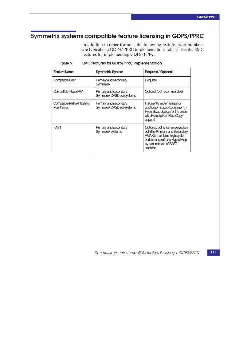
GDPS/PPRC
Symmetrix systems compatible feature licensing in GDPS/PPRC In addition to other features, the following feature order numbers are typical of a GDPS/PPRC implementation. Table 5 lists the EMC features for implementing GDPS/PPRC.
Table 5 EMC features for GDPS/PPRC implementation
Feature Name Symmetrix System Required / Optional
Compatible Peer Primary and secondary Symmetrix
Required
Compatible HyperPAV Primary and secondary Symmetrix DASD subsystems
Optional (but recommended)
Compatible Native Flash for Mainframe
Primary and secondary Symmetrix DASD subsystems
Frequently implemented for application support,operation in HyperSwapdeployment is easier with Remote Pair FlashCopy support
FAST Primary and secondary Symmetrix systems
Optional, but when employed on boththePirimary andSecondary VMAX it maintains high system performance after a HyperSwap by transmission of FAST statistics
Symmetrix systems compatible feature licensing in GDPS/PPRC 111
GDPS/PPRC
CFHINT considerations CFHINT is an architectural technique to attempt to improve the recovery time objective (RTO) for some GDPS/PPRC deployments with high data-integrity requirements (PPRCFAILURE of STOP or COND) and assumes the restart of workloads with shared data in duplexed CFs. Other than support for CGROUP FREEZE, this feature is entirely dependent upon CFRM policy definitions and GDPS STOP management (through the SA BCPii feature).
The improvements to the recovery time objective are attempted by avoiding CF REBUILD, when workloads are restarted at SITE2.
Preconditions include:
CFs are duplexed. GDPS attempts to keep CF duplexing in thesame direction as PPRC, and PPRCFAILURE policy is STOP orCOND
A PPRCFAILURE policy of STOP or COND
Trigger event for PPRC FREEZE GDPS does a Freeze&Stop. Data consistency on DASD is assured
by the FREEEZE. Data consistency between the CFs and DASD is assured by resetting all production systems.
The synchronization of data in the CFs and secondary DASD canbe achieved by RESET of the production systems during theFREEZE.
GDPS intervenes during the restart of the production z/OSsystems at SITE2 to avoid CF REBUILD of the SITE2 CFsimproving the RTO.
Preservation of the data consistency in the CF is by no means guaranteed. Failure of the CF Hint feature does not presume a failure in the Compatible Peer MC feature or the Symmetrix system.
CF Hint is entirely dependent upon GDPS/PPRC operations, and does not depend upon Compatible Peer or Compatible Native Flash features.
112 EMC Compatibility Features for IBM Copy Services on z/OS TechBook

GDPS/PPRC operations
GDPS/PPRC
GDPS/PPRC operations This section contains the following information:
“GDPS/PPRC mechanisms” on page 113
“Panel operations (GDPS operator)” on page 114
GDPS/PPRC mechanisms
GDPS/PPRC operates through several mechanisms:
GDPS Operator: By logging on to NetView, GDPS/PPRCprovides an interface for manual panel-driven operations. As hasbeen pointed out frequently in this section, avoidance ofunintended consequences to operations of remote copy volumepairs and the remote copy links is only possible throughGDPS/PPRC. GDPS also provides a web server interface as well.
Note: As a measure of GDPS’s management and control, even manualHMC actions to IPL and shutdown systems is counter indicated onceGDPS/PPRC is installed and the systems are defined in GDPS Site Table. External actions initiate TAKEOVER actions by GDPS. Manualoperations by Symmetrix inlines, SRDF/S directives, or PPRC directivesto the remote copy components should not be performed withoutdirection and informed consent of all responsible parties.
System Status and Monitoring: Through a combination of sysplexcommunications, syslog message interception (MPF), MONITORoperations, and ENF, GDPS/PPRC constantly monitors the stateof systems, sites, and remote copy mirroring, and initiatescorrective actions or warnings. GDPS/PPRC has three monitorsthat are initiated either on an interval basis or in response toGDPS operator requests. Panel and readiness statuses areupdated by initiation of the MONITORs.
Autonomic Operations: GDPS/PPRC responds to external eventsto systems and remote copy status to automatically preserve dataconsistency and system availability, as directed by policydefinitions (PPRCFAILURE and PRIMARYFAILURE).
113

GDPS/PPRC
Changes to the policy, altering the autonomic response to failures,requires changing the GEOPARM settings, either throughmodification to the PDB or dynamically updating the “splitfreeze” definitions (PPRCFAILURE and PRIMARY FAILURE) inthe panels.
Unplanned Actions (TAKEOVER SCRIPTs): These scripts, run inNetView, are often presented to the z/OS operator as WTORoptions1 in response to triggering events and subsequent to thecompletion of GDPS/PPRC autonomic operations. TAKEOVERSCRIPTS are coded and retained in the PDB.
Planned Actions (CONTROL and BATCH SCRIPTs): Thesescripts, run in NetView, are invoked either directly throughGDPS/PPRC’s panels (CONTROL SCRIPTS) or externallythrough NetView commands or z/OS MODIFY (F) command.CONTROL and BATCH scripts are coded and retained in thePDB.
GDPS operations are documented in the individual version’s Installation and Customization guides.
Panel operations (GDPS operator) GDPS/PPRC displays are not dynamic. GDPS/PPRC DASD Mirroring Status panel and Volume Status panel do not necessarily represent the current DASD mirroring status. It is recommended to operate GDPS panels with a current representation of remote copy status and refresh the screen status with the actual value of GDPS/XRC’s Global variables:
Use option “M” on the GDPS/PPRC Main panel to runMONITOR1 and MONITOR3 to validate the status.
Force the refresh of status of GDPS/PPRC DASD entities on theGDPS mirroring screens by using function key 5 (F5).
1. This process is also known as the TAKEOVER prompt. After detection of a failure, and upon completion of autonomic operations, GDPS presents tothe operator the GEO112E WTO and GEO113A WTOR, which describe the detected failure and provide the operator with the names of the availableTAKEOVER scripts.
114 EMC Compatibility Features for IBM Copy Services on z/OS TechBook

GDPS/PPRC DASD BATCH SCRIPT VPCEXIT2
GDPS/PPRC
GDPS/PPRC DASD BATCH SCRIPT VPCEXIT2 BATCH SCRIPTs can be externally initiated to the GDPS operator through the VPCEXIT2 NetView command. One advantage of the BATCH SCRIPTs, over CONTROL and TAKEOVER SCRIPTS, is their ability to accept variable parameters. A good example of such a general purpose script is the BATCH DASD SCRIPT. It is almost always coded simply as
DASD=’%1’
Where
%1 can be any valid DASD keyword specification.
It can be invoked by the NetView VPCEXIT2 command:
VPCEXIT2 nnn DASD <PARMS>
Or from the z/OS operator console:
F netview_proc,VPCEXIT2 nnn DASD <PARMS> Where
• nnn is the expected duration of the script operation
• DASD is the name of the BATCH SCRIPT, in this case DASD
• <PARMS> such as “SWITCH HYPERSWAP RESYNCH”, noquotes no “< >”
The DASD BATCH SCRIPT is almost always implemented. It enables quick operator operations of SCRIPTed operations, and in the case of GDPS/PPRC, it enables command-type execution of planned HyperSwap.
115

GDPS/PPRC
Locating PPRC error messages within GDPS/PPRC Many PPRC error messages are in the NetView LOG. Use the NetView “BR NETLOGA” to review the log on the GDPS K system (typically whichever system was acting as the master K system at the time of the incident in question).
Search NetView’s log for messages
This NetView tool is especially useful for reviewing complex GDPS operations. From the NetView operator application, issue BRLOG and fill in search values.
For example, a frequent issue of HyperSwap testing is the duration of the HyperSwap, whose various phases of operation are documented by GDPS messages, all with the character string “PHASE”, in the NetView log. Questions regarding phase duration and overall duration can be answered by searching on character string “PHASE”.
Issuing MVS system commands from NetView
NetView’s command prompt is a handy place to issue MVS system commands. Use the NetView command MVS to issue an MVS command:
MVS <any MVS command>
Example MVS D R,L MVS RO *ALL,D T
Help
GDPS/PPRC adds descriptive information to NetView’s HELPMSG command for GDPS/PPRC messages. From the NetView command:
HELPMSG GEOnnnn
GEOnnnn is the GDPS/PPRC message id.
116 EMC Compatibility Features for IBM Copy Services on z/OS TechBook

GDPS/PPRC employment of alternate subchannel support with Symmetrix systems
GDPS/PPRC
GDPS/PPRC employment of alternate subchannel support with Symmetrix systems
EMC Symmetrix systems and Compatible Peer are completely compliant with alternate sub-channel deployment with GDPS. There is no control-unit microcode support required for System z alternate subchannel set support.
Note: There are known limitations for primary device definition in MSS1 that are dependent on the z/OS release level. Except for the previously- mentioned exclusions, PPRC primary and secondary volumes share the same device address excepting the high order 0,1, or 2, which indicates the sub-channel set in the z/OS device number.
117

GDPS/PPRC
Validating GDPS autonomic operations Validation of the environment, especially GDPS/PPRC autonomic operations, is an important step in the delivery of EMC Compatible Peer and Symmetrix products in a GDPS/PPRC deployment1.
There are a variety of ways to initiate both failure to mirror (triggering the PPRCFAILURE policy) and write I/O error (triggering the PRIMARYFAILURE policy). For instance, disrupting the FICON or FCP connectivity and causing a write to a PPRC primary volume will trigger an I/O error or mirroring failure . Fortunately, there are more convenient and generally accepted mechanisms to trigger these events, as discussed in this section:
“Unplanned FREEZE” on page 118
“Unplanned HyperSwap” on page 119
Unplanned FREEZE
To trigger an unplanned FREEZE by using a batch TSO job to CSUSPEND a PPRC pair in GDPS/PPRC’s GEOPARM, the suspended pair must be in a FREEZE GROUP. The following JCL example demonstrates the use of a batch TMP to suspend a PPRC pair outside of GDPS control and trigger an unplanned GDPS/PPRC FREEZE. Validate that DASD mirroring status is OK (green), then submit the job, as shown in Figure 5 on page 119.
1. These mechanisms are employed by EMC QA, IBM Global ServicesGDPS/PPRC deployment, customers, and GDPS Certification process tovalidate FREEZE and HyperSwap autonomic operations. They aresomething of a litmus test for GDPS/PPRC implementation,configuration, and compliance, and as such are employed in everyGDPS/PPRC implementation. As the DASD vendor in a GDPS/PPRCimplementation, it is EMC’s responsibility to propose these tests (if theyhave not been proposed by other parties involved with the installation).
118 EMC Compatibility Features for IBM Copy Services on z/OS TechBook

Validating GDPS autonomic operations
GDPS/PPRC
Figure 5
Unplanned HyperSwa
Batch TMP to trigger an unplanned GDPS/PPRC FREEZE
In the above example, change the DEVN, SSIDs, VMAX serial numbers, and LCU IDs in accordance with a PPRC volume in your GDPS GEOPARM.
Again, if the PPRCFAILURE policy is STOP, then triggering an unplanned FREEZE directs GDPS/PPRC to suspend all mirroring and resets all operating production z/OS systems.
p
To trigger an unplanned HyperSwap, first validate that GDPS/PRPC is HyperSwap-ready, and then trigger an unplanned HyperSwap by using a z/OS system command to vary “offline force” a PPRC primary device in GDPS/PPRC’s GEOPARM. (Wait for a write).
As is the case with any unplanned HyperSwap, there are some risks triggering unplanned HyperSwap. Production z/OS systems that can not complete a HyperSwap will be reset by GDPS/PPRC. Additionally, it is possible that HyperSwap can take long enough to cause application disruption.
Testing of an unplanned (as well as a planned HyperSwap) should be undertaken only in a control environment, with proper change/control approval. Testing of an unplanned HyperSwap should only be undertaken after a prolonged and comprehensive testing program of planned HyperSwaps.
119

GDPS/PPRC
GDPS/PPRC networking topologies This section includes the following information:
“EMC’s role” on page 120
“GDPS topologies” on page 121
“Link budget” on page 121
“GDPS/PPRC BCRS” on page 122
“GDPS/PPRC FREEZE and GO/STOP” on page 124
“GDPS/PPRC with HyperSwap” on page 126
EMC’s role
Many factors determine the inter-site network provisioning and affect EMC’s role in the network’s architecture and procurement:
Dependencies of GDPS on sysplex connectivity
Availability requirements of the GEOPLEX policy, particularlyPRIMARYFAILURE of SWAP
Number of cross-site FICON links for normal I/O and PPRCoperational control
Number of FCP links for PPRC mirroring
Even though the required GDPS/PPRC sysplex connectivity is not within EMC’s realm of responsibility, by necessity, it dictates upon the solution network requirements that effectively limit the linkage options, mirroring distance, and directly affect the configuration of proposed Symmetrix units and the number of FICON ports. These considerations are not typical of many SRDF/S deployments (a consideration for some GDDR deployments), but they are almost always a primary concern for GDPS/PPRC deployments. Furthermore, these requirements profoundly affect the inter-site networking financial considerations and physical network deployment.
As the storage vendor in a GDPS/PPRC deployment, EMC’s role should be to configure Symmetrix solutions and mirroring components compliant with the overall networking requirements of the solution as a whole and with the understanding that the availability requirements dictate many aspects of network architecture, topology, and deployment.
120 EMC Compatibility Features for IBM Copy Services on z/OS TechBook

GDPS/PPRC networking topologies
GDPS/PPRC
GDPS topologies
GDPS topologies break down into three different categories depending on the GEOPLEX PRIMARYFAILURE policy, mirroring distance, and availability expectations:
GDPS/PPRC in a BCRS configuration
GDPS/PPRC not enabled for HyperSwap, PRIMARYFAILURE ofGO or STOP
GDPS/PPRC enabled for HyperSwap, PRIMARYFAILURE ofSWAP
The differences in the topologies and their effect on the networking provisioning are discussed in the next sections.
Link budget One additional topic in the role of a GDPS/PPRC storage vendor is EMC’s role in development of the link budget. The link budget is the explicit or implicit step in a GDPS deployment where the inter-site link topology and provisioning are decided. The types of links, protocols, bandwidth, redundancy, distance, multisite workload, and the number of links of each type determine the networking requirements and physical deployment. To a large degree EMC’s role is confined to the number of FCP and FICON links required and how GDPS/PPRC BCRS that effects the provisioning of the FCP and FICON components and linkage.
Inter-site sysplex connectivity is a complex topic depending upon many factors:
Actual z/Series processors themselves
Number and deployment of z/Series systems with systems in amultisite sysplex
Sysplex topology (base or sysplex)
Type of sysplex timing (ETR or STP)
Maximum allowable latency difference between the diversedark-fiber routing
Degree of redundancy required by the customer
The links themselves are very specialized, but their minimum requirements dictate much of the inter-site networking deployment.
121

GDPS/PPRC
One important consideration is that depending on the exact z/Series architecture some of these links cannot employ channel extension. They require either direct connectivity between z/Series processors or connectivity through dark fiber with or without DWDMs. In addition, the cross-site sysplex connectivity imposes very strict rules on the qualified DWDM systems and cards.
GDPS/PPRC BCRS
The one GDPS/PPRC topology that does not require a sysplex at both sites, BCRS deployment is a DR solution. SITE2 can operate as a “cold site”. Free from the distance restraints of an active multisite sysplex, the inter-site distance is limited only by the maximum distance supported by the FCP and FICON linkage and write I/O performance considerations.
The limited requirements for cross site FICON connectivity reduce the need for FICON ports and provisioning for VMAX engines.
An active GDPS/PPRC K system is still required (it still has all the same isolation and connectivity requirements), but it operates at SITE1. There is a dormant K system deployed at SITE2 that will become the kernel of recovery operations, DASD recovery, production z/OS system restart, and workload restart at SITE2.
Only PRIMARYFAILURE of and GO or STOP. HyperSwap is NOT feasible (the sole GDPS K system’s local DASD is assumed to fail with the SWAP triggering event).
From a GDPS/PPRC perspective, this solution has very unique GDPS networking requirements:
No cross-site sysplex linkage. SITE2 has no active system in theproduction sysplex.
Mirroring linkage can employ any physical deploymentconsistent with the SRDF/S FCP RDF linkage and performancerequirements of the z/OS system and applications (response timeand network bandwidth).
Requires very limited cross-site FICON connectivity to controlPPRC operations and maintain the dormant K system.
Operational overview in the event of an actual DR reflects the lower expectations of availability due to the lack of an active GDPS/PPRC K presence at the recovery site.
122 EMC Compatibility Features for IBM Copy Services on z/OS TechBook

GDPS/PPRC networking topologies
GDPS/PPRC
Manually IPL the recovery GDPS/PPRC K system in predefined,un-mirrored storage at SITE2 with a valid PDB and GEOPARMconsistent with SITE1.
CRECOVER the DASD at SITE2.
IPL the recovery z/OS systems using either standard actions orCONTROL scripts.
Expect elongated RTO due to the manual aspects of recoveryoperations.
Figure 6 illustrates a BCRS topology.
123

GDPS/PPRC
Figure 6 GDPS/PPRC BCRS architecture
GDPS/PPRC FREEZE and GO/STOP
This is the archetypical GDPS/PPRC deployment. Prior to HyperSwap deployments, this was the predominate topology. It consists of a multisite sysplex, with one or more K systems, and the Master K system deployed at SITE2. Workload is deployed with processing at only SITE1 (single-site workload) and production FICON connectivity is contained within a site (limited inter-site FICON connectivity for PPRC operational control and operational management).
In the event of a SITE1 failure, the K system at SITE2 offers a “TAKEOVER prompt” providing options to recover DASD, as well as systems and restart workload using TAKEOVER scripts at its disposal.
Linkage requirements:
Cross-site sysplex consistent with the sysplex architecture andz/Series systems. Again, the sysplex protocols cannot undergoany protocol conversions, and these links are typically deployedover a DWDM and dark-fiber infrastructure.
SRDF/S FCP linkage for Compatible Peer.
Cross-site FICON for GDPS management of PPRC mirroring andK systems operations.
As in the case of BRS configuration above, the limited requirement for cross site FICON connectivity (non HyperSwap) should reduce the requirements for FICON ports and VMAX engines.
Having DWDMs simplifies the networking solution for the cross-site FCP and FICON connectivity. It does require EMC’s active participation in the link budget and the DWDM card selection consistent with the bandwidth, redundancy requirements for the FCP and FICON links and the Symmetrix system.
124 EMC Compatibility Features for IBM Copy Services on z/OS TechBook

GDPS/PPRC networking topologies
GDPS/PPRC
Figure 7 illustrates a FREEZE and GO/STOP solution.
Figure 7 GDPS/PPRC FREEZE STOP/GO network provisioning with DWDM
This topology more closely resembles the illustration on “GDPS/PPRC components ” on page 77 . Typically, all links employ the DWDM and dark-fiber network (even the TCP/IP and HMC network employing inter-site connectivity through the DWDMs).
125
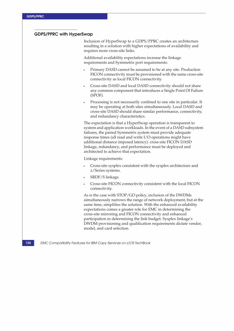
GDPS/PPRC
GDPS/PPRC with HyperSwap
Inclusion of HyperSwap to a GDPS/PPRC creates an architecture resulting in a solution with higher expectations of availability and requires more cross-site links.
Additional availability expectations increase the linkage requirements and Symmetrix port requirements:
Primary DASD cannot be assumed to be at any site. ProductionFICON connectivity must be provisioned with the same cross-siteconnectivity as local FICON connectivity.
Cross-site DASD and local DASD connectivity should not shareany common component that introduces a Single Point Of Failure(SPOF).
Processing is not necessarily confined to one site in particular. Itmay be operating at both sites simultaneously. Local DASD andcross-site DASD should share similar performance, connectivity,and redundancy characteristics.
The expectation is that a HyperSwap operation is transparent to system and application workloads. In the event of a DASD subsystem failures, the paired Symmetrix system must provide adequate response times (all read and write I/O operations might have additional distance imposed latency). cross-site FICON DASD linkage, redundancy, and performance must be deployed and architected to achieve that expectation.
Linkage requirements:
Cross-site sysplex consistent with the sysplex architecture andz/Series systems.
SRDF/S linkage.
Cross-site FICON connectivity consistent with the local FICONconnectivity.
As is the case with STOP/GO policy, inclusion of the DWDMs simultaneously narrows the range of network deployment, but at the same time, simplifies the solution. With the enhanced availability expectations comes a greater role for EMC in determining the cross-site mirroring and FICON connectivity and enhanced participation in determining the link budget. Sysplex linkage’s DWDM provisioning and qualification requirements dictate vendor, model, and card selection.
126 EMC Compatibility Features for IBM Copy Services on z/OS TechBook

GDPS/PPRC networking topologies
GDPS/PPRC
Figure 8 illustrates GDPS/PPRC with HyperSwap linkage.
Figure 8 GDPS/PPRC with HyperSwap network
The most important differentiator are the number of links to support the cross-site FICON DASD access, which in turn supports transparent FICON access to DASD after a HyperSwap, as well as FICON connectivity required of potential multisite workload.
This requirement for higher availability results in increased FICON connectivity requirements that must be addressed by sufficient network connectivity, bandwidth and FICON ports.
127

GDPS/PPRC
128 EMC Compatibility Features for IBM Copy Services on z/OS TechBook

5
Compatible Extended (XRC)
This chapter includes the following information on Compatible Extended (XRC), also known as z/OS Global Mirror:
Compatible Extended (XRC) overview………………………………..130 XRC components…………………………………………………………………….132 XRC planning overview checklist………………………………………...137 XRC operations……………………………………………………………………….139 Host time-stamping requirements………………………………………...144 Description of XRC components…………………………………………….145XRC TSO commands……………………………………………………………….173 Ordering XRC MC features for XRC implementations…………175Designing an EMC XRC solution for z/OS……………………………176Diagnostics: MODIFY ANTAS000 commands……………………….185XRC Performance Monitor (XPM)…………………………………………..187
Compatible Extended (XRC) 129

Compatible Extended (XRC)
Compatible Extended (XRC) overview Compatible Extended (XRC) is a relatively new EMC Enginuity feature. Several additional feature enhancements in Enginuity 5875 have significantly improved the compatibility of this offering on Symmetrix systems, Incremental Resynchronization (IR) for GDPS/MzGM, and Enhanced Multi-Reader (MR).
The Extended Remote Copy Enhanced Multiple Reader feature is a performance feature and is typically employed by most XRC installations. The PPRC/XRC Incremental Resynchronization feature is required only in GDPS/MzGM when it is implemented with incremental resynchronization capability.
XRC is a remote copy solution, principally for z/OS implementations, but can also be used with z/VM guests capable of time stamping write I/Os. When properly sized and managed, XRC can deliver very low Recovery Time Objectives and scale to very large configurations with a single time consistency. Due to XRC’s operational complexity, it is almost always managed with GDPS/XRC.
Features and components
Some of XRC’s features and components include:
Asynchronous remote copy solution, mirroring primary DASD,typically over significant geographic distances, to secondaryDASD. When XRC is properly implemented, remote copyoperations should impose a minimum of impact to anapplication’s write I/O performance.
XRC is a combination of hardware and software components. Itrequires specially licensed microcode features on the primarySymmetrix, cross-site channel connectivity, specially configuredz/OS infrastructure, the System Data Mover components (SDM)at the recovery site, as well as secondary DASD, and frequently, atertiary DASD capacity.
XRC formation of dependent write consistency in the secondaryDASD is based on time stamping of write I/Os when anapplication writes records. Each application write is timestamped by the host operating system (z/OS, z/VM, and
130 EMC Compatibility Features for IBM Copy Services on z/OS TechBook

Compatible Extended (XRC) overview
Compatible Extended (XRC)
z/Linux guest under z/VM), and the writes to all the secondary volumes are applied in a manner that retains the time consistency of the initial writes (not necessarily in the same order).
XRC can be used for business continuity solutions, typically fordisaster recovery, as well as site migration. XRC can operateeither in XRC mode or MIGRATION mode.
Does not impose a manufacturer pairing requirement on primaryand secondary volumes. Secondary volumes can be anycompatible CKD device. The secondary volume must be of equalor greater capacity.
XRC provides the primary remote copy component ofGDPS/XRC implementations.
XRC microcode is licensed, but the System Data Mover (SDM) ispart of DFSMS distribution and is part of the z/OS operatingsystem.1
Remote Copy operation is provided by the System Data Mover(SDM) address space on a z/OS system. However, even a modestXRC implementation (a few TB) requires a notable configurationeffort to create the SDM environment.
XRC’s SDM component requires significant processing power,but much of this requirement is zIIP processor capable.
While it is possible to start XRC for remote copy by installing the functional microcode and starting the SDMs, stable world-class implementations are achieved only with extensive planning and monitoring of many components.
1. Significant operational components, such as GDPS/XRC and XPM, are licensed software.
131

Compatible Extended (XRC)
XRC components Figure 9 illustrates XRC components as typically configured in business continuity application.
Figure 9 XRC components
The following describe the components in Figure 9.
1. Production site: A complex of z/OS systems. A single timeconsistency requires that the production systems all share acommon time source.
132 EMC Compatibility Features for IBM Copy Services on z/OS TechBook

XRC components
Compatible Extended (XRC)
2. Production systems: z/OS or z/VM systems capable of timestamping write I/Os to primary XRC volumes.
3. Time-stamped I/O: Of production writes to primary volumes bythe operating system to create.
4. primary DASD: A Symmetrix system running the XRC-licensedmicrocode. Primary DASD subsystems from different vendorscan be configured into a single time consistency. The primaryDASD is FICON connected to the z/OS resident SDM systems.VMAX systems employed as Primary XRC DASD only requiresFICON connectivity. The SDM connectivity should only employA ports and should not share these ports with productionworkload. VMAX employed as Primary XRC DASD requires noSRDF connectivity for XRC replication.
a. Sidefile on primary queued cache structure to retain writeupdates until they are processed by the SDM. The sidefile is acache resource independent of the LRU management of othercache resources. Each microcode session (4b) manages its ownsidefile.
b. XRC microcode sessions on the primary DASD subsystemmanage the records retained in the sidefile and provide themto the SDM in response to the SDM's XRC read requests (ReadRecord Set CCWs). These microcode sessions are in aone-to-one relationship with reader tasks in the SDM.
c. Resynchronization Bit Tables: The microcode sessionsmaintain two bit tables for every primary volume to enableresynchronization after planned and unplanned suspension.Tracking of updates to the primary DASD is constantlyperformed. On a specified basis, the older bit table is clearedout and becomes the current bit table. The previous bit table isretained for resynchronization. Bit tables are swapped underthe direction of the SDM while a volume is duplexed. Whenthe volume is suspended, this swapping ceases. When startingresynchronization (TSO COMMAND XADDPAIRSUSPENDED), the SDM's COPY tasks read a volumes's twobit tables, OR the two tables together, to determine whichtracks must be read from the primary DASD. Next, thechanged tracks are read to resynchronize the primary andsecondary volume.
133

Compatible Extended (XRC)
d. Utility devices for SDM readers on primary DASD LCUsservice the read of record sets from the SDM's readers'sidefiles. XRC advanced features require "fixed" utilitydevices. Multiple utility devices should be created in eachLCU in the Symmetrix Primary DASD subsystem. Thesevolumes should be as small as possible (one cylinder) andmust be dedicated to XRC operations. Fixed utility devices arenot remotely copied.
e. Primary XRC volumes grouped into an SCSESSION (see 8e),must be in the same LCU. A primary volume belongs to oneSCSESSION.
f. Primary LCU: The primary volumes and utility devices in areader are bound to single LCU.
5. Channel extension architecture: FICON connectivity between theSDM z/OS system and the primary Symmetrix DASDsubsystems. This can take many forms depending on networkavailability, distance and z/Series processor channels.
a. Direct FICON, or FICON, DWDM, and dark fiber. Someapplications with low tolerance for any synchronousmirroring write degradation employ XRC for DR at shortdistances. Some customers have acceptable FICONperformance at distances up to 300 km (with repeaters).
b. Symmetrix VMAX arrays and z/Series z/10 or later supportExtended Distance FICON (EDF), combined with multi-reader feature to reduce the effect of IU pacing.
c. Channel Extension hardware (also known as spoofing)consists of local and remote channel extenders to: 1) Alter theRead Record Set (RRS) channel programs to reduce latencyand improve channel throughput; 2) Enable FICON protocolconversion to different network topologies, such as SONNETor GigE. Many customers employ XRC remote copy atcontinental distances continue to require Channel Extensionhardware. XRC has been tested at half the circumference of theEarth using links over channel extension.
6. Business continuity site: Representative architecture of an XRCbusiness continuity site.
134 EMC Compatibility Features for IBM Copy Services on z/OS TechBook

XRC components
Compatible Extended (XRC)
7. z/OS systems to host the SDM address space(s), varying from 1 -16 systems per CEC (LPAR restriction per CEC). These aretypically z/OS systems dedicated to SDM operations. They runthe SDMs during XRC mirroring and are generally abandonedduring DR operations.
8. XRC address spaces and TCBs.
a. ANTAS000 system address space: Used for communicationsbetween TSO and ANTAS0nn (SDM) address spaces.
b. ANTMAIN: Point-in-time address space.
c. ANTCL000 optional cluster address space: Used to managetime consistency when SDMs are clustered.
d. ANTAS0nn SDM address space: A component of z/OS thatmanages the SCSESSIONs (s), up to 20 SDMs per z/OS.
e. SCSESSIONS (also known as Readers): Group volumes withinan LCU. Originally, an SCSESSION was a reader. However,with the introduction of Multi-Reader feature (EnhancedReaders) an SCSESSION can be composed of multiple readers(one base reader and multiple auxiliary readers). There can beup to 80 readers per SDM Address Space. However, forperformance considerations an SDM should be limited to 40readers, though 32 is recommended and enforced formulti-reader configurations.
9. Secondary DASD subsystem: DASD subsystems from anymanufacturer. They do not require specialized microcode. Theyonly require FICON connectivity and do not need to beprovisioned with SRDF ports. Due to the intense write operationsassociated with the SDM JOURNAL Control Data Sets, VMAX asa secondary DASD subsystem is an excellent candidate for FASTprovisioning.
a. Secondary volumes: The same model density as primaryvolumes; however, they can be from any manufacture and donot require XRC microcode feature.
b. System Data Mover (SDM) control data sets (CDS): TheJournal, CONTROL, STATE, Master, and Cluster data sets.Note, that the correct configuration of the control data sets(which data sets, properly named and correctly allocated)must exist prior to starting XRC.
135

Compatible Extended (XRC)
10. XRC Scalability: Provided by SDM clustering and SDM coupling.Thirteen SDMs are in a Cluster. Fourteen clusters (or SDMs) arecoupled a MASTER.
11. TSO Commands: Command and control through TSO commands(or ASM API).
136 EMC Compatibility Features for IBM Copy Services on z/OS TechBook
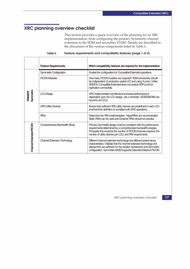
Compatible Extended (XRC)
XRC planning overview checklist This section provides a quick overview of the planning for an XRC implementation, from configuring the primary Symmetrix channel extension to the SDM and secondary DASD. Details are described in the discussion of the various components listed in Table 6.
Table 6 Feature requirements and compatibility features (page 1 of 2)
Feature Requirements Whichcompatibility features arerequired for theimplementation
PRIM
ARY
Sy
mm
etrix
Symmetrix Configuration Enable the configuration for Compatible Extended operations.
FICONModules Howmany FICONmodules are required? SDMconnectivity should be independent of production systemI/O and using A ports. Unlike SRDF/A, Compatible Extended does not employ RDF ports for replication connectivity.
LCU Design XRC implementation architecture and peak performance is dependent upon the LCU design. (As a reminder, SCSESSIONS are bound to an LCU).
XRC Utility Devices Ensurethat sufficient XRCutility devices arepredefined in each LCU and that their definition is compliant with XRC operations.
PAVs Determine the PAVimplementation. HyperPAVs are recommended. Static PAVs can be used and Dynamic PAVs should be avoided.
Cha
nnel
Ext
ende
d FI
CO
N
Comprehensive Bandwidth Study Primary Symmetrix design must be consistent with the performance requirements determined by a comprehensive bandwidth analysis. Principally thiswould be the number of FICONchannels required, the number of utility devices per LCU, and PAVrequirements.
Channel Extension Technology Different channel extension technology has different performance characteristics. Validate that the channel extension technology and deployment aresufficient for the solution architecture and Symmetrix configuration. Symmetrix DASD supports Extended Distance FICON.
XRC planning overview checklist 137

ements and compatibility features (page 2 of 2)
Services on z/OS TechBook
SDM
Arch
itect
ure
z/OSSystems for SDMs SDMsystems are typically hosted on dedicated z/OS systems. In GDPS/XRCimplementations these must be dedicated z/OS systems at the recovery site. The implementation architecture is highly dependent upon the IOCDS design.
LPARs SDMperformance is highly dependent upon the z Architecture LPAR definitions: Memory, channel connectivity, and MIPs.
FICONConnectivity SDMaddress space requires FICONconnectivity to the primary Symmetrix system.
SDMcontrol data sets The SDMrequires control data sets for operations. Optimal SDM operations and performance is highly dependent upon the correct allocation of these data sets. In addition to the aforementioned performance requirements, the SDMcontrol data sets, particularly the journal data sets, have significant physical and performance storage requirements.
Seco
ndar
y D
ASD
Feature Requirements Ensurethat the correct features areinstalled on the secondary DASD Symmetrix. Typically FlashCopy is enabled and sufficient capacity is provided as“tertiary” DASD for disaster recovery operations.
Secondary Symmetrix Ensurethat the DASDsubsystemis designed correctly asarecovery system. Typically, these systems have at least twice the capacity of the primary Symmetrix. Insuresufficient FICONconnectivity for SDM write IOto XRC secondary volumes and JOURNAL data sets. The SDMwill do approximately twice the write IOas primary DASD.
Symmetrix configuration file Settings Compatible Extended is not configured, but Compatible Native Flash is configured.
Cabling Insurethat theSDMandrecovery systems have thecorrect access to the z/OSvolumes they require.
Secondary DASD The XRCsecondary volumes and JOURNAL data setsvolumes have unique VOLSER naming requirements. Secondary LCUs should resemble the primary LCUs.
PAVs For optimal performance, the SDMshould use HyperPAVs for the secondary DASD.
Compatible Extended (XRC)
Table 6 Feature requir
138 EMC Compatibility Features for IBM Copy

XRC operations
Compatible Extended (XRC)
XRC operations This section contains the following information:
“XRC operations overview” on page 139
“Extended Remote copy data flow” on page 140
“SDM Remote copy operations” on page 141
“XRC Copy operations” on page 141
“XRC MONITOR I/O” on page 142
“XRC XADVANCE and XRECOVER operations” on page 142
XRC operations overview
Once XRC mirroring is enabled (SDM address space is started and TSO commands are issued to relate primary volumes to secondary volumes), the operating system at the primary site begins to time stamp write I/Os to primary volumes. Large complexes of production systems require a common time source, such as a sysplex timer facility. XRC is an asynchronous mirroring technology. As soon as the write is retained in the Symmetrix’s primary DASD subsystem’s cache sidefile, the application is allowed to continue operations asynchronous to the mirroring operations.
In addition to the expected LRU cache management of the writes, a copy of each write and the time stamp of the write are retained by the Symmetrix microcode in a queued structure in the cache known as the sidefile. Normal cache retains only the most recent update of a record. The sidefile must retain all updates during the processing by XRC (from the time of the write until the SDM secures the write on secondary DASD).
At the secondary side, the SDM address space dispatches the readers to simultaneously read the records in the Symmetrix system’s sidefile. Technically, the readers actually read the records (CCW is known as a Read Record Set) from the Symmetrix system’s sidefile using the address of a utility device. Typically, utility devices are un-mirrored devices (also known as fixed utility devices).
Primary volumes within an LCU are grouped into several SCSESSIONs, belonging to one reader or multiple readers. The multiple reader feature is deployed either through the use of PAVs or multiple fixed utility devices. Historically, the reader is associated
139

Compatible Extended (XRC)
with one fixed utility device. An SCSESSION (sometimes called a reader) can only contain volumes in a single LCU (SSID).
Extended Remote copy data flow
1. Residuals (update writes) are accumulated in the sidefile. Thereare three mechanisms for dispatching the readers by the SDM toread those residuals:
a. When a threshold is surpassed, the Compatible Extendedmicrocode sends an interrupt to SDM (XRC PARMLIBthreshold).
b. If there were sufficient residuals after last read (XRCPARMLIB threshold), then the SDM immediately redispatchesthe readers.
c. SDM is polling. (Set by XRC parmlib parameterSHADOW.ReadDelay, the default is 0.5 seconds.)
2. The SDM gets buffers for all the readers and dispatches all of itsreaders to perform read operations against the utility devices.
3. Once all the readers complete their read of record sets from theprimary DASD sidefile, the records are put into the SDM’s buffersas time groups. If there were sufficient residuals remaining afterthe last read, then redispatch the readers at step 2. Otherwise,wait for another interrupt or polling interval.
4. Using data from previous reads-in-time groups and time groupsfrom recent reads, the SDM then composes consistency groups(CGs) from the time groups. A CG represents a slice of time thatcomprises all updates read by the readers. (Note: some readersmay have no updates during that interval, but the CG is stillvalid.)
5. If this is an XRC SDM (not a MIGRATION SDM), the CG is thenqueued for write to a JOURNAL. Otherwise, for MIGRATIONSDM, skip to step 8.
6. A JOURNAL task writes the CG to the next JOURNAL andupdates the control data set.
7. If the SDM is COUPLED, the SDM then updates its JOURNALtime in the COUPLE data set, (Note that lacking a JOURNALTIME, a migration SDM cannot participate in a COUPLEDsession.)
140 EMC Compatibility Features for IBM Copy Services on z/OS TechBook

XRC operations
Compatible Extended (XRC)
8. The SDM queues the CG for write to secondary volumes. TheSDM:
a. Combines possible CG.
b. Eliminates unnecessary writes.
c. Orders writes based on optimum write performance.
9. CG is written to the secondary DASD. All writes for CG mustcomplete before secondary write subtask can start next CG write.
10. SDM updates secondary time in MASTER COUPLE data set.
11. Buffer is released.
SDM Remote copy operations
The SDM’s READERs issue specialized Read Record Set (RRS) CCWs to the sessions utility devices (UD) to read the write records retained in the sidefile. The SDM also issues directives indicating when the data is secure at the remote site, and when the XRC Microcode session can delete the records from the sidefile.
XRC Copy operations
The SDM will direct COPY operations under two instances:
During initial COPY, when XRC is directed by an XADDPAIR toremote copy, a primary, and a secondary volume, SDM readstracks directly from the primary volume. (The primary volumemust be online to SDM.) See description for XRC TSO commandXADDPAIR.
Incremental Copy is when XRC is directed by an XADDPAIRSUSPENDED command to resume suspended remote copyfollowing a volume suspension. SDM calculates the tracks out ofsynch based on OR’d update (bit) tables on the primary DASD,and then reads the changed tracks directly from the primaryDASD.
XRC’s volume copy operations are considerably different than its remote copy operations.
141

Compatible Extended (XRC)
The CCWs are very different for COPY and REMOTE COPYoperations. The copy tasks read data directly from the primaryvolumes, whereas readers remotely copy by reading update datafrom the sidefiles through the utility devices.
The dispatchable operations are very different. Mirroringoperations are performed by the reader subtask, and copyoperations are performed by the copy tasks.
The number and aggregation of copy tasks are controlled by theirown parameters in the XRC PARMLIB. (See the discussion onXRC PARMLIB, SCSYNCH.) Remote Copy operationalparameters are grouped into SHADOW section. Volume copy’sparameters are grouped into VOLINIT section.
XRC MONITOR I/O
The SDM periodically reads statistical MONITOR data from the microcode sessions then retains that performance data in the SDM’s STATE data set (MONITOR members). This information is principally used by XPM. (See “XRC Performance Monitor (XPM) ” on page 187.) The MONITOR I/O is performed approximately once every 10 seconds and is an important diagnostic, performance, and operational aid.
XRC XADVANCE and XRECOVER operations
Normally the SDM is responsible for remote copy operations, initial copy, and resynchronization operations. But under two special cases, XADVANCE and XRECOVER, the SDM is restarted to provide special operations against the secondary DASD.
XRECOVER restarts the SDM address space to ready the XRCsecondary DASD for recovery operations. When restarted byXRECOVER, the SDM ensures dependent write consistency byapplying all necessary consistency groups recorded in the controldata sets (principally the JOURNALS). The SDM then relabels theXRC secondary volumes with the same VOLSERs as the XRCprimary volumes. Under special conditions, the XRECOVERSDM can actually be started against the tertiary DASD (theFlashCopy targets). Doing so requires not only the use of specialkeyword parameters (ONLINE or TERTIARY), but also usuallyrequires specific GRS settings to avoid conflicting operations
142 EMC Compatibility Features for IBM Copy Services on z/OS TechBook

XRC operations
Compatible Extended (XRC)
between the XRECOVER SDM and ongoing SDM operations. This technique is typically employed by GDPS/XRC. XRECOVER’s operations are recorded in the SYSLOG.
XADVANCE shares some of the same functionality asXRECOVER. XADVANCE restarts the SDM address space to“advance” the secondary DASD to the most recent time possible,as permitted by the valid data in the SDM control data sets(principally CGs recorded in the JOURNALs). XADVANCEdiffers from XRECOVER in that it does not relabel the secondaryDASD.
143

Compatible Extended (XRC)
Host time-stamping requirements Time-stamping of write I/Os is required (common time source) by the SDM to form time consistency and results in dependent write consistency. Assigning a time stamp to a write I/O is entirely the responsibility and operation of the production system at the primary site. Consequently, if the primary site’s production workload spans multiple System z CECs and production systems (z/OS, z/VM) share the DASD and require application restart enforced by a single time consistency (sysplex operations), then the production systems must share the same system time (coordinated time network), typically implemented through STP (or legacy ETR sysplex timers).
Employment of the new SupressTimestamp XRC parameter on the SDM systems is highly recommended.
144 EMC Compatibility Features for IBM Copy Services on z/OS TechBook

Description of XRC components
Compatible Extended (XRC)
Description of XRC components This section describes the following XRC components:
“Symmetrix SIDEFILE” on page 145
“Sidefile resource management” on page 146
“READERTIMEOUT value” on page 148
“Volume pairs” on page 149
“Utility device” on page 149
“SCSESSION and readers” on page 150
“Multi-readers” on page 151
“Copy operations” on page 152
“System Data Mover (SDM) address space” on page 153
“SDM buffers and memory requirements” on page 155
“System zResources” on page 156
“z/OS SDM systems” on page 156
“SDM sizing” on page 157
“SDM scalability” on page 157
“XRC parameters” on page 160
“XRC PARMLIB hierarchy” on page 169
“XRC control data sets” on page 170
Symmetrix SIDEFILE
The XRC control unit sidefile is physically a cache resource, but dedicated for queued storage of write updates (also known as “residuals”). The size of the sidefile is mediated on VMAX by the cache allocation policy setting in the Symmetrix configuration file.
Managed differently than LRU cache, the XRC microcode sessions must retain a copy of every write (no folding of write I/Os, such as is the case with SRDF/A) until such time as the SDM indicates that the write has been secured at the secondary site.
If the number of residuals in the primary DASD exceeds user specified thresholds, then the XRC Compatibility microcode will employs one of two protection mechanisms for cache overrun on a
145

Compatible Extended (XRC)
primary volume depending on threshold settings and the device blocking or write pacing settings established for the volume pair.
Sidefile resource management Over the years, several mechanisms have been implemented to avoid exhaustion of the sidefile resource and to determine what actions to take when the sidefile resources have become exhausted. There are specific limitations for the sidefile1:
The space consumed by all sidefiles cannot exceed the Symmetrixcache allocation policy definition
Residual count cannot exceed 128K per sidefile
If these resource limitations are exceeded, then XRC microcode sessions must cease operations and suspend. There have been several microcode features implemented to penalize sidefile cache users and restrict the use of sidefile resources: Device Blocking and the newer Write Pacing. In addition, there are now features that enable a more graceful shutdown of XRC operations that limit adverse effects on production DASD.
Device blocking Device blocking was the original mechanism to reduce consumption of sidefile resources. If the number of residuals for a volume exceeds the device blocking threshold (XRC PARMLIB SHADOW.DeviceBlockingThreshold default 20), the microcode would issue a long busy for 500 ms every 1000 ms (1/2 second every one second) to all reads and writes as long as the residuals exceeded the threshold. As a mechanism for limiting the consumption of sidefile resources, it had many shortcomings2 and has been supplanted by the write pacing feature3.
The TSO XADDPAIR command parameter of DONOTBLOCK disables device blocking for a volume.
1. Values for 2107 implementation. 2105 implementation is 63K residuals.2. Among the short comings, all reads and writes were penalized; using
device busy increased IOSQ time for a device, which WLM attempts torectify by assigning additional Dynamic PAVs.
3. Device blocking was likened to “slamming on the brakes.”
146 EMC Compatibility Features for IBM Copy Services on z/OS TechBook

Description of XRC components
Compatible Extended (XRC)
Write pacing Write pacing is a newer feature designed to avoid exhaustion of sidefile resources by inhibiting discretionary workload through elongation of write I/O to that volume. It is a granular mechanism for specifying, by volume, the amount of write elongation to apply1. Write pacing should not be viewed as a mechanism to replace adequate network and SDM design. Rather, it is best employed to limit the consumption of sidefile resources by discretionary workload or as a means to ensure continued operations by XRC when the ability of the SDM to read residuals from the sidefile is extremely limited due to external events.
Operation The XRC microcode injects disconnect time on write I/Os to a volume whose residuals have exceeded the write pacing threshold (or device blocking threshold if no write pacing threshold is uniquely specified). Adding disconnect time reduces the number of write I/Os an application can perform with the intent of reducing sidefile consumption by that workload.
Write pacing specification Specification is by volume pair when the volumes are XADDPAIRed and on a 0 to 15 scale, the maximum degree of write elongation to apply. In addition to a new threshold specification (PARMLIB SHADOW.WrtPacingResidualCnt default 80), there is a default specification for write pacing (PARMLIB SHADOW.DfltWritePacingLvl default 0). To improve the reporting of write pacing, a value has been added that suppresses the reporting of write pacing (PARMLIB SHADOW.PacingReportThreshold default 10). Note that default level write pacing and volume write pacing can be set dynamically using the XSET command.
Suspend Instead of Initially, when the sidefile resources were exhausted, the microcode Long Busy (SUSLBUSY) reacted by issuing an extended long busy condition, which would
often result with production application and system stability issues. If the number of residuals exhausted the sidefile resources, the microcode would respond by issuing LONGBUSY to volumes in the LCU until the number of residuals was less 1K less than the exceeded threshold.
However, a recent enhancement to XRC enables the microcode sessions to simply suspend mirroring when sidefile resources are exhausted. Suspend Instead of Long Busy is enabled using the TSO
1. Write pacing is likened to “tapping on the brakes.”
147

Compatible Extended (XRC)
XRC command XSET parameter SUSLBUSY (YES | NO), the default value is NO.1 The XRC PARMLIB setting for SILB is SHADOW.SuspendOnLongBusy (YES|NO). In almost all environments, SUSLBUSY should be set to YES. This should be set prior to issuing any XADDPAIR commands.
READERTIMEOUT value
Correctly setting the READERTIMEOUT value in architectures employing channel extension technology is vitally important because the routers local to the primary DASD often do not report channel disconnect with networking problems2. Consequently, the microcode sessions in the PRIMARY DASD are unaware that the SDM is unable to read from the primary DASD. This can quickly lead to severe write pacing, as the residuals exceed the device blocking thresholds. READERTIMEOUT provides the microcode sessions a time limit to wait for read I/O from the sessions, after which they suspend.
The microcode sessions always maintains the current time out value, which is decremented by seconds when the SDM does not contact the microcode session and reset to the time out value each time the SDM contacts the microcode. Session suspension occurs when the time out value reaches zero. Since each reader has its own timer the microcode sessions suspend when their time out is exhausted and threshold is subsequently exceeded. In real world scenarios suspension occurs for some readers very quickly (at the reader time out) while others will suspend much later. Because the SDM is unable to communicate to the microcode sessions, it may or may not suspend.
Relevant settings:
XRC PARMLIB.SHADOW.DeviceBlockingThreshold(nn, 0-255, default is 20, dynamic)
XRC PARMLIB.SHADOW.WritePacingResidualCnt (nn, 0-255, default is 80, dynamic)
XRC PARMLIB.SHADOW.StorageControlTimeout (00.00.00-18.00.00, default is set by CE)
1. When XSET SUSLBUSY is combined with SSID parameter, then thesetting for the specified SSID is updated. Without an SSID setting, itapplies to subsequently added SSIDs to that SDM. Review GDPS/XRCDASD MIRRORING SCREEN option XSET for GDPS support.
2. In normal FICON (and ESCON) connectivity, when the last path to a hostis lost (the light goes out), the microcode will suspend the XRC sessions.
148 EMC Compatibility Features for IBM Copy Services on z/OS TechBook
Description of XRC components
Compatible Extended (XRC)
Volume pairs
XRC volume pairs consist of:
Primary volume on a Symmetrix system with the licensed XRCcompatibility feature. The primary volume “belongs” to a readerwithin an SDM for the life span of the remote copy pair.
Secondary of equal or greater capacity on any 3390 compatiblesystem (any vendor).
XRC volume pairs are created by the XADDPAIR TSO command or API directive.
Utility device
A utility device provides the device address for an SDM’s reader to read record sets from the Symmetrix XRC sidefile. Utility devices are very tightly bound to a reader and LCU (SSID). They are an important design consideration for performance and continuous operation of XRC. Typically, the design of an LCU must accommodate a sufficient number of previously defined fixed utility devices for initial operations and should accommodate changes required to address operational and performance aspects. Additional requirements for utility devices can arise in response to address reader performance or SCSESSIONs that have different mirroring characteristics. (See different session types discussed in Chapter 7, ”Three-Site Solution GDPS/MzGM.”)
Each SCSESSION must have at least one utility device1.
There are two types of utility devices:
Fixed: The reader issues reads for the SCSESSION to a particular utility device that was defined using the XADDPAIR command with secondary VOLSER of XRCUTL. The reader always uses the same real device address, hence “fixed” utility device.
Floating: The reader issues reads for the SCSESSION to any primary volume in its session without a reserve. If there is a reserve against the current utility volume, the SDM “floats” the utility device to another device in the SCSESSION.
1. Often casually referred to as “utility volume”.
149

Compatible Extended (XRC)
Originally, fixed utility devices could not have a reserve from production system (the SDM could not read through the reserve), but that restriction has been lifted. However, it is still a recommended practice for the utility devices to be undefined or offline to the production systems.
Floating utility devices are a newer feature than fixed utility devices, but fixed utility devices are more common than floating and are required by the most recent of XRC features, multi-reader and incremental resynchronization of GDPS/XRC. In these cases, it is important to set XRC parameters to require FIXED utility devices.
Floating utility devices are implicit. There is no XADDPAIR with the XRCUTL secondary VOLSER specification in an SCSESSION. In addition, unless fixed utility devices are required, when fixed utility devices are unavailable, the utility device can “float”.
Important XRC PARMLIB settings controlling utility devices:
XRC PARMLIB SHADOW.RequireUtility(YES|NO) (Default is YES. This is not a dynamic parameter.)
XRC PARMLIB SHADOW.UtilityDevice (FIX|FLOAT) (Default is FIX.)
SCSESSION and readers
From the SDM’s perspective, an SCSESSION is a group of volumes in an LCU that all share the same two-character session ID. Originally the reader, SCSESSION, and microcode session were linked on a one-to-one-to-one basis. Each reader was linked to its utility device. The SDM dispatched the reader to read record sets from the sidefile for the volumes in the SCSESSION. An SCSESSION and the microcode session is established when the first volume is defined using the two character SCSESSION_ID, either with:
A fixed utility device with its secondary VOLSER of XRCUTL, or
A floating utility device (used the first time a volume pair isdefined with the SCSESSION_ID).
The reader uses the utility device to read record sets for write I/Os to the primary volumes from the session’s sidefile.
Primary volumes are joined to an SCSESSION and microcode session when an XADDPAIR command is issued specifying the session’s designated two-character SCSESSION_ID.
150 EMC Compatibility Features for IBM Copy Services on z/OS TechBook

Description of XRC components
Compatible Extended (XRC)
An SCSESSION or reader cannot span LCUs. Its volumes are all restricted to a single LCU. Readers with the same SCSESSION_IDs in different LCUs are in fact different SCSESSIONs.
Multi-readers
The multi-reader feature (enhanced readers) is a performance feature that enables the SDM to simultaneously perform multiple read record sets for a SCSESSION. Single readers can become a bottleneck in XRC performance due to the inherently longer latency and greater response times in reading the residuals from the sidefile than the local applications writing to the sidefile. This can cause residuals to build up in the sidefile in readers with volumes servicing many writes, increasing the recovery point objective and negatively impacting the stability of the solution. In addition, it is more difficult to balance and tune workloads using single-reader sessions. Multi-readers enable much larger SCSESSIONs, with more volumes and reduce the amount of manual tuning required.
Instead of one sidefile and one microcode session, the SCSESSION has as many sidefiles as it has multiple sessions. The writes to an XRC primary device are spread over the multiple sidefiles, enabling the SDM to issue multiple read record sets simultaneously to each microcode session.
Symmetrix multi-reader sessions have one primary session and up to thirteen auxiliary sessions, for a total of fourteen sessions. Most customers employ a default of three or four readers per SCSESSION, with some performance sensitive readers employing more. SCSESSIONs with multi-readers enjoy a nearly linear improvement as readers are added, until the links become saturated or residuals in the sidefiles become zero. As the number of readers increases, the SDM can offload the number of residuals much more effectively.
The first utility device must be a fixed utility device(s). Auxiliary sessions can have fixed utility devices or PAV aliases. HyperPAVs or static PAVs for the utility device are recommended. Dynamic PAVs are not recommended.
Note: The maximum number of readers in an SDM is reduced with multiple readers. Normally with single readers, SCSESSIONS per SDM should be limited to 40. With multi-readers enabled, the number of SCSESSIONS is restricted to 32 per SDM.
151

Compatible Extended (XRC)
Important XRC parameters managing enhanced readers:
XRC PARMLIB SHADOW.AllowEnhancedReader(YES|NO) Enables the SDM to employ enhanced readers. Note the default setting of NO disallows the use of multi-readers. XRC PARMLIB SHADOW.NumberReaderTask ((scsn,#tasks),…) The number of tasks supporting each SCSESSION IDs. Specification of a default value for all SCSESSIONs is specified by (*,n), where n is the number of multi-readers. If multiple fixed utility devices (XRCUTL volumes) are defined for a SCSESSION, then the reader uses all the fixed utility devices. XRC PARMLIB SHADOW.MAXTotalReaderTasks(32-80) 80 if AllowEnhancedReader(NO). 32 if AllowEnhancedReader (YES). However, for performance reasons, the number of readers/SDM should never exceed 40 in an SDM. XRC PARMLIB SHADOW.RequireUtility(YES|NO) Should always be specified as YES. Specification of YES requires the use of fixed utility devices. XRC PARMLIB SHADOW.UtilityDevice(FLOAT|FIX) Enables the floating utility feature. It should always be specified as FIX.
Copy operations
Copy operations is a distinct operation within the SDM address space and is mediated by several XRC parameters. Copy tasks read the tracks directly from the primary DASD and write directly to the secondary volumes. Copy tasks are invoked dynamically, initially as a result of XADDPAIR of volume pairs or after suspension of remote copy, as a result of “XADDPAIR SUSPENDED”. Initial copy provides several operational modes (FULLCOPY, NOCOPY, and QUICKCOPY), but the safest is FULLCOPY, which copies all tracks ever used but puts no reserve on the volume’s VTOC. 1
1. QUICKCOPY only copies tracks currently allocated but it must hold areserve on the VTOC, which is counter indicated in channel extensionarchitectures. Reserves are not well tolerated by production sysplexsystems and completely contrary to the implementation requirements ofHyperSwap implementations. NOCOPY is never recommended.
152 EMC Compatibility Features for IBM Copy Services on z/OS TechBook

Description of XRC components
Compatible Extended (XRC)
The total number of COPY tasks is mediated by several XRC parameters and the total number of LCUs:
XRC PARMLIB VOLINIT.MaxNumberInitializations(0-45). (Default is 4.)
XRC PARMLIB VOLINIT.InitializationsPerPrimary(0-45. (Default is 2.)
XRC PARMLIB VOLINIT.InitializationsPerSecondary(0-45). (Default is 2.)
The number of copy tasks can also be dynamically managed by the TSO command XSET subparameter SYNCH and SCSYNCH. Default copy task values are frequently considered insufficient.
System Data Mover (SDM) address space
The SDM address space provides remote copy services between primary and secondary volumes. This includes inventory management of volume pairs, reading updates from primary DASD Symmetrix system, ensuring dependent write consistency on the secondary DASD volumes and recovery services.
There are a number of important considerations for sizing the SDM and the z/OS system and LPAR within which it must operates.
SDM (re)Start Modes The SDM operates under a variety of other purposes:
Started with the XSTART TSO COMMAND (or API), the SDMmanages the mirroring operations, reading record sets fromprimary DASD, forming consistency groups, and updating thesecondary DASD in a manner to retain dependent writeconsistency. The SDM also performs many of XRC TSO commanddirectives.
Started with XRECOVER, the SDM recovers the secondary DASDby ensuring that all consistency groups in the JOURNAL data setsare rewritten to secondary DASD. If the SDM was coupled, theXRECOVER operation determines the maximum JOURNAL timeof all the coupled SDMs and applies the residuals up to themaximum JOURNAL time. The SDM also relabels all thesecondary with primary volsers.
Started with XADVANCE, the SDM performs similar operationsof the XRECOVER, but does not relabel the secondary volsers.
153

Compatible Extended (XRC)
In a clustered SDM environment, one SDM address space perz/OS system operates as the cluster address space coupling theSDMs on that z/OS system.
The SDM address spaces system task names are all of the form ANTAS0nn (nn: 01-15). The SDM address space can be identified with a particular XRC SDM_ID through the XSTATUS TSO command.
SDM operations In addition to employing readers to read residuals from the sidefile of the primary Symmetrix system, the SDM provides other services:
Initial full copy and incremental resynchronization copy (aftersuspension using bit tables) of tracks from primary XRC volumesto secondary XRC volumes.
Management of the resynchronization bit tables on the primarySymmetrix system.
Periodic capture of performance data from the primary DASDsubsystem and retention in control data set.
Management of the volume pair status and remote copy, addingvolume pairs, deleting volume pairs, suspending remote copy ofvolume pairs.
Formation of consistency groups, managing the write of CG toJOURNAL data sets, control data sets (when required), andscheduling the CG writes to secondary DASD.
Notification to primary DASD microcode sessions when residualshave been secured on secondary DASD and sidefile resources canbe released.
SDM session types An SDM can operate in one of two SESSIONTYPES:
XRC is the normal mode of remote copy operations for disasterrecovery services. XRC operates in recovery mode utilizingcontrol data sets (JOURNAL DSs and CONTROL DS) toguarantee dependent write consistency of the secondaryvolumes.
MIGRATE mode is employed for data migration or volumeremote copy when dependent write consistency is not required.This mode of operation is often utilized to manage the productionsystem’s infrastructure volumes.
Due to the nature of its work, an XRC SDM (as opposed to a MIGRATION type SDM) is required to perform efficiently. A typical
154 EMC Compatibility Features for IBM Copy Services on z/OS TechBook

Description of XRC components
Compatible Extended (XRC)
SDM requires at least 1.5 to 1.6 GB of virtual memory, the vast bulk of which must be in buffers that should not page.
SDM buffers and memory requirements
The number of buffers represents the amount of virtual memory available to an SDM’s operations. As such, the buffers represent an important sizing, performance, and capacity resource. The buffer capacity and usage is controlled by several parameters in the STORAGE category, many of which have insufficient default values and should be reviewed for more appropriate specification. The size of a buffer is 60 KB.
XRC PARMLIB STORAGE.BuffersPerStorageControl(100-25,000). (Default is 576.)
XRC PARMLIB STORAGE.PermanentFixedPages(0-9,999).
XRC PARMLIB STORAGE.ReleaseFixedPages(YES|NO). (Default is NO.)
XRC PARMLIB STORAGE.TotalBuffers(100-999999). (Default is 25,000.)
XRC PARMLIB STORAGE.IODataAreas(100-9999). (Default is 256.)
Buffer capacity is a critical resource. The SDM will slow down reader dispatching (reader pacing) if the number of available buffers drops below a threshold. Reader pacing usually results in a prompt build up of residuals on the Symmetrix primary DASD and an increased probability of write pacing. In addition, it might also lead to the SDM stalling, XRC suspension, and abnormal termination of the SDM address space.
It is important to ensure the z/OS system is properly configured for sufficient private area and paging space to accommodate all the SDMs intended for that z/OS system.
Likewise, ensure that the LPAR itself is defined with sufficient real memory to support the z/OS system and all SDM address spaces. A single SDM requires about 1.5 GB of virtual memory. The z/OS system must be able to satisfy the virtual memory requirements for all SDMs that run on that system.
Review the Advanced Copy Services manual "Planning for Extended Remote Copy" chapter, for guidance on real and virtual storage requirements for the SDM and the z/OS system.
155

Compatible Extended (XRC)
System zResources
Optimal SDM performance is highly dependent upon the physical resources dedicated to its operation in the LPAR definition.
The LPAR must have sufficient real memory to support all SDMs that run in the z/OS system in that LPAR. Typically, that is 1.5 GB of real memory for each SDM, in addition to the real memory requirements of the z/OS system itself.
The LPAR requires FICON channel extension to the primary DASD, with sufficient bandwidth to read the updates from the primary Symmetrix DASD subsystem. The SDM also requires sufficient connectivity to the secondary DASD. The SDM is required to do approximately double the write workload as the production systems. (CGs are recorded in the JOURNAL data sets and then the updates are written to the secondary DASD.)
The SDM can use ZIIP specialty engines, if they are available to the LPAR and enabled in the XRC PARMLIB.
z/OS SDM systems
Typically, the z/OS systems employed for the SDMs are dedicated systems, with unique system generation, availability goals, and operational goals then typical production systems. Almost always they reside at the remote site, especially when operated over geographically significant distances and for disaster recovery purposes1.
While SDM z/OS systems are often cloned from production systems, they have very different configurations:
Virtual memory is designed for the large SDM address spaces.
SDM z/OS systems are not general purpose systems dedicatedperformance of the SDM address spaces.
From a licensing standpoint, they are usually cost justified assingle-purpose DR systems.
1. Channel Extension technology for XRC is engineered for efficientoperation when pulling the Read Record Sets. It is extremely inefficientpushing the individual updates to secondary volumes.
156 EMC Compatibility Features for IBM Copy Services on z/OS TechBook

Description of XRC components
Compatible Extended (XRC)
I/O gen requirements are very different. Typically, both primaryand secondary DASD and control data sets are genned asavailable and online to the SDM systems. Any FlashCopy tertiaryDASD is typically offline to the SDM z/OS systems1. Turn offreserves and disable SMF recording of DASD statistics, especiallywhen the solution employs channel extender technology. Areserve from the SDM system can hang production systems if thereserve is coincident with a link failure. Guidelines for SMFrecording and reserve/release issues are documented in theDFSMS Extended Remote Copy Reference Information for AdvancedUsers.
SDM z/OS systems are intended for 7X24X365 unattendedoperations.
SDM sizing
Sizing the SDM system depends upon several issues, including the write workload, number of volumes, and number of readers. Typical ‘rules of thumb’ follow:
1500 to 1800 volumes or 3 TB to 5 TB
40 readers without multi-reader
32 readers with multi-reader
SDM scalability
A single SDM implements its own dependent write consistency through the formation of consistency groups and by controlling the sequential writes of the consistency groups to the secondary DASD.
IMPORTANT
A single SDM puts severe constraints on the scalability of an XRC solution and is insufficient for modern environments, where solutions of hundreds of terabytes are required.
1. GDPS/XRC and GDPS MzGM impose additional I/O GEN requirementsfor the GDPS SDM systems and K system.
157

Compatible Extended (XRC)
XRC has addressed scalability though the technology of SDM coupling and its adjunct technology SDM clustering. Coupled XRC is sometimes referred to as CXRC.
In addition to the software enablement of SDM coupling and SDM clustering, proper sizing of the z/OS systems that run the SDMs is very important. Fully defined SDMs need approximately 2 GB address spaces, and much of that private storage must be fixed. Consequently, adequate and effective scalability depends on SDM z/OS systems with large virtual space running in LPARs with sufficient real memory and processor MIPs.
Coupling of SDMs does not force the SDMs to actively maintain point-in-time consistency. Coupling enforces a maximum JOURNAL time (also known as maximum RECOIVERY time) between the SDMs enabling XRECOVER to recreate dependent write consistency by moving slower SDMs forward in time based on consistency group data in the JOURNALs.
SDM Coupling, This is the oldest coupling technique. Originally it allowed up to 14 Coupled XRC (CXRC) SDMs to form a mutually self-managed time consistency. (No SDM
was allowed to write a consistency group to its secondary volumes ahead of (more recently) than the JOURNALed consistency group time of another SDM.)
SDM coupling was introduced with two significant capabilities:
The maximum number of SDMs in a z/OS was increased fromone to five (address spaces ANTAS0nn).
Up to 14 SDMs could couple themselves in a Master Couple dataset to interlock and self-manage a joint recoverable consistency.
JOURNAL and SECONDARY times for each SDM are retained in the Master Couple data set. The Master data set is a one cylinder data set (one track is reserved for mutual use and each SDM has use of one track).
When a system is initially coupled into a Master session 1 it is unlikely that it is interlocked with the already existing coupled members. Interlock is also synonymous with a joint consistency time, or as it is also sometimes expressed, max journal time.
1. In actuality, the “Master Session” does not exist. Coupled SDMs maintaina state of interlock on their own.
158 EMC Compatibility Features for IBM Copy Services on z/OS TechBook

Description of XRC components
Compatible Extended (XRC)
A joint consistency time is necessary and sufficient for XRECOVER to create data consistency between coupled SDMs.
Two TOD values are important to the interlocking of an SDM. The JOURNAL TOD (the TOD of the consistency group most recently written to the JOURNAL, effectively the exposure time ) and the secondary TOD (the TOD of the consistency group most recently written to the secondary DASD, effectively the delay time ). An SDM is interlocked when its JOURNAL time is more recent (newer) than the secondary times for all other interlocked SDMs.
Alternatively, an SDM cannot interlock if it has written CGs to secondary DASD more recently than any other SDM’s JOURNAL time. The interlock condition allows XRECOVER to resolve time differences when it rewrites all valid consistency groups in the SDMs’ JOURNAL data sets1. XRECOVER of coupled SDMs relies upon the fact that data on the secondary DASD can be moved forward in time based on consistency groups s in the JOURNAL, but it is impossible to erase data hardened to the secondary DASD.
However, the structure of coupling technology had inherent scalability limitations (maximum of 14 SDMs). Consequently, XRC scalability has been extended through the newer feature SDM clustering based on z/OS systems.
SDM Clustering SDM Clustering is enabled by three major enhancements to CXRC:
The maximum number of SDMs address spaces in a single z/OSsystem has been increased from 5 to 20.
A new CLUSTER SDM (name ANTCL000) has been introduced tomanage the consistency time for SDMs running in the same z/OSsystem.
1. Secondary DASD volumes are inherently inconsistent during normalRemote Copy. The write order of consistency groups on secondaryvolumes is based on time stamping, but the write order within aconsistency group is not performed in time stamp order (folding ofduplicate writes is performed a priori). Furthermore, the individual SDMs make no attempt to write consistency groups to secondary based on other SDMs writes to secondary DASD. It is up to XRECOVER to resolve allintermediate inconsistencies by rewriting all valid consistency groups inthe SDM JOURNALs up to the maximum JOURNAL time in the COUPLE data set.
159

Compatible Extended (XRC)
To couple to a master data set, SDMs on the same z/OS systemeither cluster and then couple or couple directly. However, ifthere is a cluster SDM defined on a z/OS system, then an SDMmust employ clustering in order to couple.
Up to fourteen SDM address spaces on an SDM z/OS system can now be clustered. A cluster consists of one CLUSTER SDM (address space ANTCL000) and thirteen XRC SDM address spaces (address spaces ANTAS0nn). The CLUSTER SDM coordinates the consistency time of the thirteen XRC SDMs and manages the cluster’s joint consistency time in the MASTER COUPLE data set. The individual JOURNAL and SECONDARY consistency times for the XRC SDMs are retained in the CLUSTER data set, which is a one-cylinder data set. The CLUSTER SDM records the individual SDM consistency times in its CLUSTER data set.
Thus, the maximum attainable scalability for clustering of a single time consistency is 182 SDMs (14 CLUSTERs/MASTER * 13 SDMs/CLUSTER). While it is difficult to put an exact number on this, potentially that would be 182 * 32 LCUs (32 SCSESSIONs/SDM recommended with multi-readers), or about 5376 LCUs (SSIDs), performance considerations notwithstanding.
Clustering SDMs is mediated by two XRC parameters:
XRC PARMLIB.STARTUP.ClusterMSession(sys_nameMSESSIONID)
XRC PARMLIB.STARTUP.ClusterName(sys_name CLUSTERID)
XRC parameters
The importance of the XRC parameters with regards to sizing, tailoring, operations, and tuning should not be underestimated. Many of these parameter settings have co-dependences, not only with GDPS parameters, XRC control files, and SDM definition, but also with Symmetrix configuration file settings.
Detailed information regarding the XRC PARMLIBs and the parameters can be found in the Advanced Copy Services manual.
160 EMC Compatibility Features for IBM Copy Services on z/OS TechBook

Description of XRC components
Compatible Extended (XRC)
Parameter name This manual employs an open type nomenclature1 for the XRC convention parameter names. XRC PARMLIB members employ a hierarchy of
major sections BITMAP, MONITOR, SHADOW, STARTUP, STORAGE, and VOLINIT, and within each major section its parameters. Within this manual when a parameter is referenced, it will include a reference to its MAJOR section. That format is:
Major_SECTION_name.parameter
Significant XRC There are significant XRC parameters that should be specified in XRC parameters large XRC implementations, and includes to avoid using the
defaulted values. In addition, VMAX arrays and the Compatible Extended feature have different optimum operational characteristics than other manufacturer’s DASD subsystems. This would be reflected in different tuning values for VMAX arrays. Some of the recommendations, listed in Table 7 on page 162, result from testing with VMAX, some are recognized as best of breed recommendations in large XRC implementations for business continuity solutions.
1. An editorial style sheet.
161
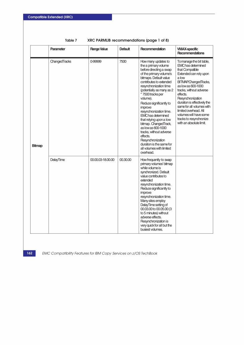
recommendations (page 1 of 8)
Parameter RangeValue Default Recommendation VMAX-specific Recommendations
Bitmap
ChangedTracks 0-99999 7500 Howmany updates to the a primary volume before directing a swap of the primary volume's bitmaps. Default value contributes to extended resynchronization time (potentially asmany as 2 * 7500 tracks per volume). Reduce significantly to improve resynchronization time. EMC has determined that relying upon a low bitmap. ChangedTrack, as low as 600-1000 tracks, without adverse effects. Resynchronization duration is the same for all volumes with limited overhead.
To manage the bit table, EMC has determined that Compatible Extended can rely upon a low BITMAP.ChangedTracks, as low as 600-1000 tracks, without adverse effects. Resynchronization duration is effectively the samefor all volumeswith limited overhead. All volumes will have some tracks to resynchronize with an absolute limit.
DelayTime 00.00.03-18.00.00 00.30.00 Howfrequently to swap primary volumes' bitmap while volume is synchronized. Default value contributes to extended resynchronization time. Reduce significantly to improve resynchronization time. Many sites employ DelayTime setting of 00.03.00 to 00.05.00 (3 to 5 minutes) without adverse effects. Resynchronization is very quick for all but the busiest volumes.
Services on z/OS TechBook
Compatible Extended (XRC)
Table 7 XRC PARMLIB
162 EMC Compatibility Features for IBM Copy

Compatible Extended (XRC)
Table 7 XRC PARMLIB recommendations (page 2 of 8)
Parameter RangeValue Default Recommendation VMAX-specific Recommendations
Monitor
MonitorOutput ON|OFF OFF Controls monitor statistical recording to the STATE data set MONITORmembers. Recommendedsettingis ON; ONis required if XPMis installed.
Shadow
AllowEnhancedReader YES|NO NO Support for Enhanced Readers, required for multi-reader support. Also, specify SHADOW.UtilityDevice(F IX) and SHADOW.RequireUtility( YES),
DeviceBlockingThreshold 0-255 20 Keep default, recommend controlling sidefile resource utilization with write pacing, instead of device blocking SHADOW.DfltWritePacin gLvl,
MaxBytesTransfered 0,60000 to 9999999
512500 The maximumnumber of bytes written to secondary DASD. EMC has tested this up to 4M,
MaxTracksRead 1 to 246 64 Number of RRS (read record set) commands that areissuedinasingle channel program. Maximumvalue can be 246 (but you can specify 1 to 255, all values >246 are treated as 246). Should be set to at least 124.
Description of XRC components 163

recommendations (page 3 of 8)
Parameter RangeValue Default Recommendation VMAX-specific Recommendations
Shadow (cont.)
MaxTotalReaderTasks 32-80 80 or 32 The total number of readers (both base and auxiliary) allowed in an SDMaddress space. If AllowEnhancedReader( NO), then default is 80. If AllowEnhancedReader( YES), then default is 32. Set AllowEnhancedReader( YES) and use default of 32. If not using enhanced readers, then the practical limit is 40. If more than 40 readers are required, create a new SDM, balance the readers and COUPLE. Ensurethere issufficient real and virtual memory to support a new SDM address space in the z/OS system.
NumberReaderTasks (id,n) Id: session idor "*" n: 0:14
(*,0) Specifies whether auxiliary readers are to be used and their numbers by SCSESSION or by default. Note that this parameter corresponds to the number of MR sessions in a SCSESSION, and by reserving 2 for system use on Symmetrix, the maximumnumber of tasks is reduced by 2. However, in practice the number of MRrarely exceeds 5.
Symmetrix systems support up to 14 sessions (typically, 1 primary and up to 13 auxiliary tasks).
Services on z/OS TechBook
Compatible Extended (XRC)
Table 7 XRC PARMLIB
164 EMC Compatibility Features for IBM Copy

Compatible Extended (XRC)
Table 7 XRC PARMLIB recommendations (page 4 of 8)
Parameter RangeValue Default Recommendation VMAX-specific Recommendations
Shadow (cont.)
PavVolumes 1-9 1 Number of parallel write I/O tasks to be used for writes to a secondary volume when PavByteThreshold is exceeded. Performance problems on secondary volumescanimpact XRC performance enough to cause write pacing. Recommendation is to employ HPAVon secondary volumes. PavVolumesettingof 3is usually sufficient.
ResidualLefttoRead 1-500 128 Number of residuals remaining in a sidefile that directs the SDMto immediately dispatchthe readers to reread the residuals, rather than waiting for an attention interrupt or the read delay.
ReadDelay 100-5000 100 Duration of the reader polling interval in milliseconds. Symmetrix systems have been stress tested at 100 to 200 resulting in lower average RPO(less than 1 second). Lower ReadDelay results in more aggressive operation by the SDM and can potentially reduceaverageRPO, but can also increase the MIPs used under low- activity periods.
Description of XRC components 165

recommendations (page 5 of 8)
Parameter RangeValue Default Recommendation VMAX-specific Recommendations
Shadow (cont.)
StorageControlTimeout 00.00.00 - 18.00.00
CE-defined default for Symmetrix array
Establish site default value based on consulting with the customer, especially in implementations employing FICON channel extension with protocol conversion. Note this is set on an LCU-by-LCU basis upon the creation of the first microcode session inthe LCU. Parmlib variable only establishes time out value for new LCUs, not existing ones. To update time out on existing LCUs, usethe XRCTSO command XSETwith the TIMEOUT parameter.
SuspendOnLongBusy YES|NO NO Suspend instead of long busy, unless otherwise indicated, set toYES. This is not dynamic for existing sessions. Use XSET SUSLBUSY for existing XRC sessions.
WritePacingResidualCnt 0-255 80 Threshold for initiation of write pacing. This value is multiplied by 64 to determinetarget residual threshold by volume to begin write pacing. This setting has performance and Recovery Time Implications. Consult with the customer. Note the relationship with VOLINIT.HaltThreshold.
Services on z/OS TechBook
Compatible Extended (XRC)
Table 7 XRC PARMLIB
166 EMC Compatibility Features for IBM Copy

Compatible Extended (XRC)
Table 7 XRC PARMLIB recommendations (page 6 of 8)
Parameter RangeValue Default Recommendation VMAX-specific Recommendations
Startup
STARTUPzIIPEnabled YES|NO NO If SDMprocessor has ZIIPprocessors, thenthe recommendation is to employ zIIPEnabled(YES).
SuppressTimeStamp YES|NO NO Direct DFSMSto suppress time-stamping fromTHIS system. Use this parameter on the SDMsystem(s) to ensure that the SDM system(s) do not inadvertently update the microcode time on the primary Symmetrix system. Default setting on SDMsystems can enable inadvertent updates to time and make it difficult for the SDMto form Consistency Groups.
Storage
BuffersPerStorageControl 100-25000 576 Default is usually inadequate for most large XRC implementations. Set to 25000.
PermanentFixedPages 0-9999 8 Default is too lowfor most large XRC implementations. It can be set up to 9999.
TotalBuffers 100-999999 25000 Most significant SDM employ the maximumof 25,000.Specificationhas a direct effect on the amount of virtual and real memory required by the z/OS systemand LPAR.
Description of XRC components 167

recommendations (page 7 of 8)
Parameter RangeValue Default Recommendation VMAX-specific Recommendations
Volinit
InitializationsPerPrimary 0-45 2 The number of copy tasks per primary LCU. Two is usually too low andincreasesinitial copy and resynchronization timing. But too many cop tasks can cause over initiation issues. Four to six is usually sufficient. Monitor resynchronization and increase dynamically with XSET SCSYNCH
InitializationsPerSecondary 0-45 2 This has the same issue as InitializationsPerPrimary. Set to the same value.
I/ODataAreas 100 to 9999 256 Real Storage Allocation for the SDMchannel programs. Settings for this parameter should be based on the number of volume pairs in the session. See Advanced Copy Services Guide for settings.
HaltThreshold 0-65535 5120 Keep higher than write pacing threshold, which has a more effective mechanismfor managing residuals.
MaxNumberInitializations 0-45 4 Total number of COPY tasks. Specify an adequate number given the settings for InitializationsPerPrimary and InitializationsPerSecond ary. Can dynamically reset with XSET SYNCH.
Services on z/OS TechBook
Compatible Extended (XRC)
Table 7 XRC PARMLIB
168 EMC Compatibility Features for IBM Copy

Compatible Extended (XRC)
Table 7 XRC PARMLIB recommendations (page 8 of 8)
Parameter RangeValue Default Recommendation VMAX-specific Recommendations
Volinit (cont.)
TracksPerRead 0-15 3 This has the same value as TracksPerRead.
SecondaryDeviceRange (nnnn-nnnn) No default. Consider employing SecondaryDeviceRange or SecondaryVolserPattern toprotect primary DASD.
SecondaryVolserPattern VOLSER pattern) NONE Employ a good naming standard for secondary VOLSERs to protect primary DASD and specify this pattern.
Flags IGNORE_INTERRUPTS OFF ON|OFF SettingtoONcanreduce the MIPs and likely overhead on VMAX arrays. Aggressive settings on read delay and residuals left to read reduce the need for the SDMto be interrupted. EMCrecommends setting IGNORE_INTERRUPTS to ON
In addition to the XRC PARMLIB recommendations, anecdotal evidence from stress tests suggests that Symmetrix system's Compatible Extended performs more effectively when the number of sidefiles per SSID is limited.
XRC PARMLIB hierarchy
For more information about the XRC PARMLIB hierarchy and search order, refer to the DFSMS Advanced Copy Services Guide, “Administering your extended remote copy environment” section. Given the scale of modern DASD subsystems, in most cases of multi-vendor deployments, an SDM would likely only administer a single DASD subsystem. Consequently, differences in parameters specific to Symmetrix systems can be easily resolved by providing
Description of XRC components 169

Compatible Extended (XRC)
XRC PARMLIB members specific to those SDMs managing Symmetrix systems.
XRC PARMLIB There are explicit and implicit rules regarding the search order an members SDM employs in locating the parameter libraries and their members.
SYS1.PARMLIB(ANTXIN00) When the SDM is started, it searches the z/OS system PARMLIB concatenation for the ANTXIN00 member. Typically the ANTXIN00 members supply global naming parameters (NAMES.Hlq, NAMES.MHlq, STARTUP.Parmlib, and STARTUP.Global) used for establishing the naming standards for XRC and SDMs’ control data sets. Foremost amongst the data sets name standards are those SDM PARMLIBs with the operational parameters through the STARTUP.Hlq and STARTUP.MHlq parameters. Parameter specifications in the ANTXIN00 are usually confined to the STARTUP category.
The NAME parameters can only be specified in the ANTXIN00 member.
Hlq.XRC.PARMLIB(global | ALL) The ALL and global members (indentified by the STARTUP.Global parameter) typically supply the enterprise’s default parameter settings for all SDMs.
Hlq.XRC.PARMLIB(SDMid) SDMid members typically provide override parameter settings for individual SDMs. The SDM’s name is associated with the member name.
XSET PARMLIB member The XSET PARMLIB command can be used to refresh an SDM’s parameters.
XRC control data sets
Depending on the SESSIONTYPE, an SDM will potentially allocate different data sets. A SDM of SESSIONTYPE MIGRATE will only require a STATE data set. An SDM of SESSIONTYPE XRC will at least allocate its control data set and as many JOURNAL data sets as exist.
State data set The State data set retains the operational definition and domain of an SDM. It should be allocated as a PDSE. The State data set retains the status of all volume pairs. The SDM stores MONITOR performance
170 EMC Compatibility Features for IBM Copy Services on z/OS TechBook

Description of XRC components
Compatible Extended (XRC)
information in special members. It retains information regarding the CLUSTERED and COUPLED status of an SDM. Cluster SDMs require their own State data set.
Control data set The control data set identifies valid consistency groups in the JOURNAL files. It is required by SESSIONTYPE of XRC, but not used by SESSIONTYPE MIGRATE.
Journal data sets There are between two to sixteen data sets principally used for journaling consistency groups (CGs) prior to writing the records in the CG to the secondary DASD (defined in multiples of 2). XRECOVER operations also exploit the JOURNALs as part of recovery operations by reading all valid CGs in the JOURNAL data sets and re-writing their records to secondary DASD.
The JOURNAL data sets are very performance sensitive. All data written to primary volumes is recorded in the form of consistency groups in the JOURNAL data sets. As much I/O goes to an SDM’s JOURNAL data sets’ volumes as is written to all primary volumes and almost as much as to all secondary volumes. Placement of these z/OS volumes and their physical definition in the secondary Symmetrix subsystem can have profound performance impact. Sizing of secondary Symmetrix DASD subsystem must account for the doubling of write I/O.
Pairs of JOURNAL data sets are generally allocated as DFSMS stripped data sets. See the Advanced Copy Services manual for details on the preferred allocation methodology. Performance problems on the JOURNAL data sets can quickly cause operational issues in the SDM and even affect the degree of write pacing on production volumes and adversely affect production and the stability of the solution.
Most serious XRC implementations employ a minimum of eight JOURNAL data sets and of those implementations, the majority use sixteen JOURNAL data sets. If a SDM is unable to write a consistency group (because all the space is exhausted by CGs awaiting write to secondary), then the SDM will ABEND.
Journals are required by SDMs of sessiontype XRC, but not required of SESSIONTYPE MIGRATE.
Cluster data set The Cluster data set is employed by the SDM address space CLUSTER SESSION (ANTCLnnn) to maintain the joint consistency time information for the clustered SDMs. The CLUSTER SESSION
171

Compatible Extended (XRC)
maintains the time consistency information for the member SDMs in a cluster.
Cluster State data sets Retains XRC monitor data for all the CLUSTERED SDMs in a cluster. It is used by XPM for reporting.
Master Couple data This is used by coupled SDMs to manage their recoverable sets consistency. With traditional coupling, the SDMs themselves manage
their own time consistency by comparing the recorded maximum JOURNAL and SECONDARY DASD consistency times of the other SDMs. In a clustered environment, the CLUSTER SDM address space manages the consistency times of its constituent SDMs and updates the CLUSTER data set. The COUPLE data set must be on a volume accessible by all coupled SDMs or their CLUSTER SDM.
Performance for the COUPLE data set is moderately critical. It is typically isolated on a volume of its own and should never share a volume with a JOURNAL data set.
The COUPLE data set is allocated in a single extent of one cylinder, with no secondary extents. Each SDM takes a single track for recording its information.
Performance Consider the following: considerations for
XRC control data sets The JOURNAL data sets should be SMS striped. MOD-3 volumes are recommended for the journals. Typically,
there will be enough cache slots so the entire volume fits in the cache, and device Write Pending limit is never reached with a MOD-3.
The I/O should be sequential on the journals, so RAID-5 7+1should be sufficient protection.
Optimal performance should be achieved by intermixing theJOURNAL secondary volumes across all physical disks. This ismost easily achieved using one disk group, with all secondaryvolumes and control data sets striped across all DAs and disks.
In a configuration with multiple secondary/tertiary DASDsubsystems, consider staggering an SDM’s SECONDARYvolumes and JOURNALs over multiple DASD subsystems toavoid “doubling up” a hot spot.
On TIERED frames, the FC disks are recommended. EFD can alsobe used, but avoid SATA.
172 EMC Compatibility Features for IBM Copy Services on z/OS TechBook

Compatible Extended (XRC)
XRC TSO commands Table 8 provides a brief description of XRC TSO commands.
Table 8 XRC commands (page 1 of 2)
Command Purpose SDMstatus
XADDPAIR Several uses: • Identifies the pair(s) of primary and secondary volumes (by VOLSER). Note the
discussion on GDPS/XRC GEOPARM. Puts the volume pair on the COPY queue for initial copy.
• Identifies which SCSESSION primary volumes reside (which reader). • Identifies REAL utility devices. (Their definition is not remotely copied.) • Restarts mirroring for suspended volumes (XADDPAIR …SUSPENDED) by
putting the volume pairs on the COPY queue.
Up
XADVANCE Used when the SDMis down to read the valid consistency groups in the JOURNAL data set and write themto the secondary DASD. Not frequently employed.
Down
XCOUPLE Several uses: • Couples SDMs or CLUSTERs to the MASTER COUPLE data set when the SDM
is up. • Uncouples SDMfromthe MASTER couple data set when SDMis up.• Removes an SDMfromthe MASTER data set if the SDMis not available
(PURGE).
Either up or down depending on the function
XDELPAIR Deletes the relationship between an XRC pair. Subsequent resumption of mirroring between the pair requires an XADDPAIR and initial copy.
Up
XEND Ends the SDMenvironment for an SDM. Rarely employed. Down
XQUERY Several query functions on SDM, VOLUMEs, SCSESSIONs, parameter specifications
XRECOVER Restarts the SDMto recover the secondary DASD (or tertiary DASD), makingthosevolumes availablefor normal z/OSoperations (suchasdisaster recovery operations), and ensuring that the data on all volumes is time consistent. Its exact operation depends on the XRC operational mode when the SDMlast executed as well as whether the SDMwas XENDed. In DR operations (XRC mode1) it: • Restarts the SDMaddress space.• Reads valid consistency groups retained in the JOURNAL data sets .• Rewrites all the valid consistency groups on the apparent secondary DASD2. • Relabels the secondary volumes with their primary VOLSERs.The recovery SDMaddress space either uses the secondary volume addresses retained in the STATE data set or uses the volumes found ONLINE, when directed to use the XRECOVER ONLINEkeyword. (This is the typical process employed by GDPS/XRC implementations.)
Down
XRC TSO commands 173
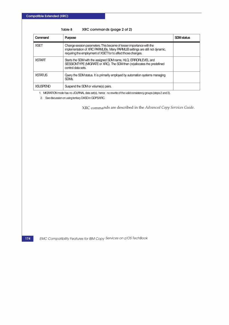
ds (page 2 of 2)
Command Purpose SDMstatus
XSET Change session parameters. This became of lesser importance with the implementation of XRC PARMLIBs. Many PARMLIBsettings are still not dynamic, requiring the employment of XSET for to affect those changes.
XSTART Starts the SDMwith the assigned SDMname, HLQ, ERRORLEVEL and SESSIONTYPE (MIGRATEor XRC). The SDMthen (re)allocates the predefined control data sets.
XSTATUS Query the SDMstatus. It is primarily employed by automation systems managing SDMs.
XSUSPEND Suspend the SDMor volume(s) pairs.
no rewrite of the valid consistency groups (steps 2 and 3).
nds are described in the Advanced Copy Services Guide.
Services on z/OS TechBook
Compatible Extended (XRC)
Table 8 XRC comman
1. MIGRATIONmode has no JOURNAL data set(s), hence
2. See discussion on using tertiary DASD in GDPS/XRC.
XRC comma
174 EMC Compatibility Features for IBM Copy

Compatible Extended (XRC)
Ordering XRC MC features for XRC implementations In addition to other Management Class (MC) features required, Table 9 lists feature order numbers typical of an XRC implementation:
Table 9 MC products for XRC implementation
Feature Name Symmetrix System Model Numbers Required/Optional
Compatible Extended Primary Symmetrix DASD Subsystems
CMPEXT Required
Compatible HyperPAV Primary Symmetrix DASD Subsystems
SYM-HYPERPAV Optional (but recommended)
Compatible HyperPAV Secondary Symmetrix DASD Subsystems
SYM-HYPERPAV Optional (but recommended)
Compatible Native Flash for Mainframe
Secondary Symmetrix DASD Subsystems
CMPNFLASH Optional, but typically required in GDPS/XRC implementations
Note: Only the primary Symmetrix DASD subsystem requires XRC feature licensing. It is not required on the secondary Symmetrix DASD subsystem. However, XRC is almost always implemented with a tertiary DASD capacity at the DR site that is implemented with DASD capacity and Compatible Native Flash.
Ordering XRC MC features for XRC implementations 175

Compatible Extended (XRC)
Designing an EMC XRC solution for z/OS The following information is included in this section:
“Implementation” on page 176
“Sidefile specification” on page 179
“Symmetrix configuration file specifications” on page 179
“Linkage and channel extension connectivity” on page 181
“FICON linkage requirements” on page 182
“XRC exploitation of PAVs” on page 183
Implementation
The following sections discuss implementation:
“Considerations for implementing a new solution” on page 176
“XRC sizing” on page 178
“Considerations for supplementing an existing solution” on page 179
Considerations for XRC must be sized for peak business workload. It is imperative that implementing a new XRC sizing studies employ data (typically SMF/RMF) that reflects
solution peak business workload.
There are many components to XRC, and a sizing study should address all components:
Number of I/Os per second: Affects not only bandwidth but alsoSDM sizing and MIP requirements .
Blocksizes of I/Os: Affects not only bandwidth but also SDM MIPrequirements (data in small blocks requires more processingpower than the same amount of data in large blocks).
Peak write (to a volume): XRC must be sized for peakrequirement component by component. Failure to account foreven a single volume’s mirroring requirements can adverselyaffect the solution’s stability.
Sidefile size: Failure to adequately size the cache requirementeffects the maximum RPO and stability of the solution.
Utility Devices: Number per LCU on primary DASD.
176 EMC Compatibility Features for IBM Copy Services on z/OS TechBook

Designing an EMC XRC solution for z/OS
Compatible Extended (XRC)
Bandwidth: A major cost component, initial costs and ongoingcosts, often a stability issue.
FICON connectivity: The geographic distance between the DSMand the primary DASD within the limitations of FICON (overdark fiber) or channel extension technology must be employed.
Connectivity redundancy: Network components fail andmirroring solutions often suffer the most during partial networkfailure.
FICON ports for mirroring: Isolated from production work.
Geographic separation and network latency: Hops add to latency,marginally increasing RPO, but also increasing the cacherequirement, and reducing the effectiveness of readers.
z/OS systems: For the SDMs, must be designed for the number ofSDM address spaces, and they often require specificSYS1.PARMLIB system set up.
GDPS/XRC requirements: K z/OS system, SDM z/OS system(s),and require sysplex enablement of the SDMs and K systems.
z/Series MIPs: ZIIP engines requirements. SDMs can use ZIIPspecialty processors for much of their processing requirements.
Real memory: Dedicated to the LPARs for SDM’s z/OS system. Itmust be adequately sized. Paging for the SDMs should beminimized.
The virtual memory sizing: For the SDM z/OS systems and SDMbuffers, the z/OS system must have adequate virtual memory forall the SDMs active.
SDM address spaces: The number, configuration, andperformance of SDM address spaces.
Readers: Each primary LCU requires at least one reader.Performance considerations for individual volumes often requirereaders dedicated to particular volumes and workloads. An SDMshould not have more than 40 readers. When multi-readers areemployed, the number of readers per SDM should be limited to32. Combine MR with HyperPAV definitions.
PAVs (HyperPAVs): Highly recommended on secondary DASD,and requires enablement through XRC PARMLIB settings.
SDM’s control data sets must be allocated according the type ofSDM:
177

Compatible Extended (XRC)
• STATE DS: One for each SDM, regardless of the SDM type.
• CONTROL DS: One for each XRC SDM.
• JOURNAL DS: The JOURNAL data sets must perform asmuch write I/O as the primary volumes. Allocation of thesedata sets for performance and adequately sized is required.two to sixteen for each SDM for XRC type.
SDMsSystem control data sets:
• PARMLIBs: The SDM attempts to allocate the local XRCPARMLIB data set, depending on setting in theSYS1.PARMLIB settings. This data set and parameters shouldbe allocated, and the PARMs should be established prior tostarting the mirroring operations.
• CLUSTER DS: One for each z/OS systems if SDM clustering isemployed.
• CLUSTER STATE DS: One for each z/OS system if SDMclustering is employed.
• COUPLE or MASTER DS: One for each time consistency ifSDMs are coupled.
Writes to secondary DASD: Secondary DASD subsystemsexperience twice as much write I/O as the primary DASDsubsystems (writes to XRC secondary volumes and JOURNALdata sets). Use of PAVs is specified in the XRC PARMLIB and ishighly recommended.
Reverse site switch: Are there requirements for a return to theproduction site after a disaster declaration?
Secondary VOLSERS: A good naming standard for the secondaryVOLSERs is recommended.
Considerations for FlashCopy capacity: Capacity, usage,performance and access.
XRC sizing Because of the architecture of XRC, it is not uncommon to actually have to size XRC based on the maximum of two business operations peaks: the maximum number of I/Os per second (small blocksize many I/Os), and the maximum amount of data (large blocksize and many I/Os per second). This is frequently encountered when XRC is deployed in the financial industry, where the daytime online
workload (small block size, many I/Os) is very different than the workload exhibited during offline processing (larger block sizes and sequential type I/O). In addition, an effective study depends on the
178 EMC Compatibility Features for IBM Copy Services on z/OS TechBook
Designing an EMC XRC solution for z/OS
Compatible Extended (XRC)
minimum SMF interval possible. Large intervals often average out workload, masking short duration peaks that on their own can seriously impact XRC operations.
Because XRC employs so many resources, XRC sizing is more than bandwidth sizing.1 Failure to adequately size any one component can adversely affect XRC performance, not only increasing XRC’s Exposure Time (RPO), but also impacting production write response time through XRC imposed write pacing, and ultimately the stability of the solution if XRC exhausts sidefile capacity.
When the SDM is unable to match application write rate, exhaustion of critical resources will happen very quickly, much quicker than typical operational response times. Either SDM buffers or sidefile can quickly become exhausted, leading quickly to SDM suspension.
FlashCopy deployment can also exhibit a detrimental operational effect on XRC performance and an awareness of XRC and FlashCopy interaction is also critical.
Considerations for An SDM can manage SCSESSIONs with different vendors (primary supplementing an DASD). But given the size of modern DASD subsystems and possible
existing solution conflicts in optimal XRC PARMLIB settings, this is unlikely.
Moving volumes under XRC (and changing VOLSERs) is supported (TDMF operations).
Sidefile specification
To address the surge in non Data Slot usage in the cache, Enginuity 5875 micro code introduces the new cache allocation policies called default and replication sidefile. A Symmetrix system employed as a primary XRC DASD subsystem must have the cache allocation policy set to "Replication_Policy".
Symmetrix configuration file specifications
In a GDPS MzGM implementation these configuration file settings must be enabled for all DASD subsystems that can be primary XRC DASD. Insure that your EMC field representative thoroughly checks these settings for correctness via Symmetrix service interface.
1. The best tool for performing XRC SDM sizing studies is RMFMAGIC, sold by Intellimagic B.V.
179

Compatible Extended (XRC)
subsystems. In addition, the SDM has specific PAV requirements, see “XRC exploitation of PAVs” on page 183.
As is the case with Compatible PEER, the configuration file settings and configuration of the primary and secondary Symmetrix systems must be compliant with Compatible Extended.
Table 10 Symmetrix Configuration File Settings for XRC enablement
Name Value Description
CKD->XRC_flags->Enable XRC Check Box Check box to enable Compatible Extended
CKD->XRC->flags->XRC Never Timeout
Check Box Leave as unchecked
CKD->XRC_flags->XRC Floating Utility Device
Check Box Froma compatibility standpoint enable this feature but disable its usage through the SDMutility deivce definitions and XRC parmlib specifications
CKD->PPRC/XRC Incremental Resync
YES| NO This feature must be enabled in GDPS/MzGM implementations employing the incremental resynchronization. Refer to “GDPS MzGM and XRC incremental re-synchronization” on page 218 for a description of the optional feature and when to enable this BINFILE setting.
180 EMC Compatibility Features for IBM Copy Services on z/OS TechBook

Compatible Extended (XRC)
Linkage and channel extension connectivity
SDM requires System z FICON connectivity to the primary DASD. However, one form or another of channel extension technology is often employed, due to the geographically significant distances encountered between the SDM systems and the primary DASD. The technology employed in the SDM’s FICON channel extension is significantly different than those technologies employed in equivalent SRDF/A’s RDF connectivity, and rarely can the SDM exploit the same network architecture and components without significant modification.
There are many considerations in the channel connectivity to consider:
Distance and latency
Physical network protocols
Designing an EMC XRC solution for z/OS 181
Name Value Description
CKD->impl_fix_part->Multi Reader XRC
1:14 This is the maximumnumber of microcode sessions for an SDM SCSESSION. The first session is the base session, additional auxiliary sessions are enabled by increasing this value. See “SCSESSION and readers” on page 150.
CKD->XRC timeout value 0:FFFF AKA Dead Reader Timer, This counter begins to decrement once the device blocking threshold has been exceeded by residuals in the side file. AMC session will suspend itself if this counter gets to zero. This parameter is of importance in implementations employing channel extensiontechnology0is the default of 120 seconds.
Memory->Cache Allocation Policy Replication_Policy Snap Default
Set to Replication_Policy on VMAX with primary XRC volumes.

Compatible Extended (XRC)
FICON pathing
Network linkage components (FICON channel extension routers or DWDM)
Protocol conversion technology
Typically, converting FICON protocol to some physical network protocol, such as GIG/E or SONNET
Performance requirements
Cost
While networking costs have historically trended downward, XRC’s networking costs are very important considerations and must be addressed early in the solution consideration
The following are typical with increased distances and latency times:
Direct FICON over DWDMs and dark fiber and multi-Reader
Extended Distance FICON and multi-Reader
Channel extenders
FICON linkage requirements
Use FICON modules on the primary Symmetrix system for the SDM’s connectivity. Guidelines include:
On VMAX arrays, use A ports before using the B ports.
Configuring all logical ports into the A port is generally preferred.
Do not configure two paths to the same LCU on the A and B ports of the same director.
For XRC readers (SDM access), use the B port if no others are available.
Typical mainframe workloads will saturate the VMAX FICON module around 7000 IOPS. Average workloads do not exceed 3500 IOPS. Peaks should not exceed 5500 IOPs. Check with performance engineering on using these numbers. However, these guidelines may need to be reduced considerably if peaks are occurring within batch or backup windows, due to larger average I/Os.
182 EMC Compatibility Features for IBM Copy Services on z/OS TechBook

Compatible Extended (XRC)
Note: The utilization of the second port of a FICON module does not increase the total workload of the module, and results in slightly higher overall response times. Avoid saturating the module and impact production workload on the A port because of SDM access through B ports.
XRC exploitation of PAVs PAVs (particularly HyperPAVs) are indicated in several aspects of SDM operation. Many of these are not automatically exploited, and require mediation through XRC settings and definitions. Consequently, for optimal operational performance HPAV specifications in the configuration file must correspond to the intended XRC operational requirements and plans.
Incorrect definition of PAVs in the configuration file, or their absence, may seriously degrade the SDM’s performance. In addition, HPAVs must be activated on the SDM system to the primary DASD in order for multi-reader to perform effectively using PAVs (as opposed to readers that use multiple fixed utility devices, which do not employ PAVs).
Table 11 lists information for PAV enablement.
Table 11 PAV enablement (page 1 of 2)
DASD Category Enablement XRC PARMLIB Setting PAV type
Secondary DASD
Enables the SDMtosimultaneously issue multiple writes in a CGto a secondary volume. Exploitation is mediated by twoparameters. When write I/O in a CGfor a secondary device > PavByteThreshold, then SDMwill use PAVs count in PavVolume to issue simultaneous writes to secondary volume.
SHADOW.PavByteThreshold Range (60000-9999999) default 512500
SHADOW.PavVolumes Range (1-9) default 1 Delays at secondary DASDs, which are not associated with FlashCopy background operations might indicate the need for increasing PavVolume setting.
HyperPAVs are recommended. but static can be employed with additional management coordinated with the production PAV definition of primary volume. Dynamic PAVs are counter-indicated.
Designing an EMC XRC solution for z/OS 183

Compatible Extended (XRC)
Table 11 PAV enablement (page 2 of 2)
DASD Category Enablement XRC PARMLIB Setting PAV type
Primary DASD fixed utility device
Enables multiple readers to issue RRS against a single fixed utility deviceinanSCSESSION. Reduces the need for multiple fixed utility devices in a single SCSESSION.
SHADOW.NumberReaderTasks Range (0-16) Default (*,0). Note, however, that it is overridden by number of fixed XRCUTL defined in SCSESSION.
Excessive accumulation of residuals associated with given readers, leading to increased EXPOSURETIME or exhaustion of SIDEFILEresources,. Suspension might indicate the need for multi-reader or increasing the NumberReaderTasks
Another indicator is excessive I/O time by a reader in relation to the XPM MONITORinterval time. Generally speaking, if a reader’s I/O time is observed exceeding half of the MONITORinterval time, itis often regarded as sufficient evidence that additional auxiliary readers are addedto the session.
HyperPAVs are recommended. Staticcanbe employedwithmanagement. Dynamic PAVs are counter- indicated.
Note: HPAVs are recommended for both primary and secondary DASD.
JOURNALs are DFSMS STRIPED and the SDM does not make use of HPAVs writing to the JOURNALs.
184 EMC Compatibility Features for IBM Copy Services on z/OS TechBook

Compatible Extended (XRC)
Diagnostics: MODIFY ANTAS000 commands The MODIFY ANTAS000 commands provide diagnostic services for display and operation of the XRC microcode sessions (including Compatible Extended sessions on Symmetrix systems and the SDMs. The diagnostic information they provide overlaps INLINE displays of the microcode sessions. Compatible Extended feature operation complies with these directives and queries.
Commands apply to XRC, FlashCopy, and Concurrent Copy sessions
Table 12 provides a brief description of the functions of the ANTAS000 commands:
Table 12 ANTAS000 command functions
CREFESH Restarts the CLUSTERsession’s address space on a z/OS system.
DELBMAP Deletes all the bitmaps in the SDM(old-fashioned) planned outage.
DUMP Dumps the SDMaddress space (see important note on following page).
DVCDATA Lists the Storage Control Sessions for a device.
IGNORE_INTERRUPTS Requests SDMignore low and high attention interrupts fromMC.
LISTDVCS Lists all devices that are part of a storage control session.
LISTSESS Lists the storage control sessions operating in a storage control.
PATHS Reports the channel path and associated path group ids for a device.
RESTART Restarts an SDM.
SCDATA Reports the detailed status of a session on a primary storage control.
SCTRAP Enables /disables problemdetermination and aids on storage control.
STATESAVE Diagnostic tool.
SUSSSESS Suspends microcode sessions (the big red switch).
TERMSESS Terminates microcode sessions.
XENDDUMP SDMdiagnostic tool.
XRCTRAP SDMdiagnostic tool.
Diagnostics: MODIFY ANTAS000 commands 185
Compatible Extended (XRC)
IMPORTANT
These commands can directly affect operations of the microcode sessions and the SDM. Always exercise caution in their use. Incorrect usage can result in session suspension, possible termination of the SDM, or termination of Remote Copy necessitating complete reinitialization and initial copy of volume pairs.
Operation and parameters are documented in the Advanced Copy Services Guide, Appendix A.
186 EMC Compatibility Features for IBM Copy Services on z/OS TechBook

XRC Performance Monitor (XPM)
Compatible Extended (XRC)
XRC Performance Monitor (XPM) A monitoring, tuning, and problem determination for XRC, XPM1
runs at the DR site alongside XRC.
XPM is probably the most important tool for managing XRC operations. A separately chargeable license by IBM, it is almost always a part of XRC engagements. XPM Real Time Monitor is frequently used in an operational setting to monitor XRC operations on a real time basis. Its mirroring status display is usually preferred over GDPS/XRC’s remote copy status display.
XPM uses the MONITOR data in the State data sets.
Components include:
Real-time monitor (under ISPF) with critical and warningthresholds
Background component to copy MONITOR data into history datasets (batch job)
History monitor to review operation in the history data sets(under ISPF)
Batch Exception monitor to issue warning messages whenoperational and performance thresholds are exceeded
Note: Invocation is very site- and configuration-dependent. XPM is usually invoked though an ISPF option, but not always. Operation requires knowledge of the SDM names, naming standards, and XPM operations.
Initial problem determination of XRC issues often starts by reviewing XPM historical data to isolate failure.
1. Originally, a closely held set of utilities, XPM was subsequently releasedas product.
187

Compatible Extended (XRC)
188 EMC Compatibility Features for IBM Copy Services on z/OS TechBook

6
GDPS/XRC
This chapter includes the following information on GDPS/XRC:
GDPS/XRC overview ....................................................................... 190 GDPS/XRC systems and DASD components ............................... 196 GDPS/XRC GEOXPARM mirroring defined ................................ 200 Locating XRC error messages with GDPS/XRC ........................... 201 Locating XRC XRECOVER report ................................................... 202 NetView operations .......................................................................... 203
GDPS/XRC 189

GDPS/XRC
GDPS/XRC overview GDPS/XRC is a business-continuity solution designed to deliver disaster-recovery solutions using XRC for long-distance remote copy. In addition, a FlashCopy capability is almost always configured and operationally employed at the recovery site to provide a testable and resilient solution and retain a viable recovery image during resynchronization.
GDPS/XRC requires significant manual setup of the XRC mirroring prior to beginning of operations. The SDMs must be ready to start up prior to starting them under GDPS/XRC control. Manual validation of the XRC and FlashCopy components prior to attempting operational control through GDPS is often performed.
GDPS/XRC features and operations
GDPS/XRC consists of a GDPSplex at a recovery site, a GDPS Ksystem, and a variable number of z/OS SDM systems running theSDMs.
GDPS/XRC runs as an application in the NetView address space.Operations of GDPS/XRC requires NetView operator logon toNetView and access the GDPS application.
Can manage multiple independent time consistencies by enabling multiple MASTER sessions.
Can direct independent testing and restart of recovery systems.
GDPS/XRC is not as particular about external operations asGDPS/PPRC. Unlike GDPS/PPRC, which FREEZEs mirroring ifa volume pair is suspended outside GDPS/PPRC, GDPS/XRCallows external operations against volume mirroring.
GDPS/XRC components
Figure 10 on page 190 illustrates the major components of a GDPS/XRC deployment.
Figure 10 GDPS/XRC components
190 EMC Compatibility Features for IBM Copy Services on z/OS TechBook

GDPS/XRC overview
GDPS/XRC
Major GDPS/XRC Not all of these components are germane to EMC’s products, roles, components and responsibilities in a GDPS/XRC implementation, but have been
included to provide a more comprehensive overview.
1. Production Site: GDPS/XRC has no presence at the productionsite.
191

GDPS/XRC
2. Production System(s): GDPS/XRC has no awareness of thenumber of z/OS systems at the production site. In fact, it has noactual awareness of even the number of systems (might beinferred through the number of systems to recover).
3. Primary DASD(s): Primary XRC DASD is defined in theGEOXPARM. Note this example illustrates a GDPS/XRCcomplex of multiple time consistencies (multiple MASTERsessions managed independently).
4. Channel Connectivity: XRC’s channel-extended FICON.
5. Business Continuance Site: A physically remote site for disasterrecovery.
6. GDPS/XRC K system: The controlling system at the recovery site.Together, the GDPS K system and the SDM z/OS systemscompose a unique sysplex. In most environments the GDPS/XRCK system actually performs the XRC recovery operations. In mostimplementations, there is only a single GDPS/XRC K system.
a. GDPS/XRC K system DASD: The local system DASD for theGDPS/K system. Note that it is extremely important to avoidany potential duplicate VOLSERs of the production systems’DASD VOLSERs. Not only would it make it difficult to bringthe intended production volumes online to the SDMs, but ifthe SDM used these volumes as primary XRC volumes, thelogical integrity of the recovery set of DASD could be criticallyimpaired.
192 EMC Compatibility Features for IBM Copy Services on z/OS TechBook

GDPS/XRC overview
GDPS/XRC
IMPORTANT
This is not a casual warning. GDPS’s GEOXPARM definitions are device-addressing based, but XRC XADDPAIR is VOLSER based. When a CONFIG is loaded, GDPS resolves the intended XRC pairings based on the VOLSERs found at the device addresses specified in the GEOXPARM. If subsequent to that operation a local device with the same VOLSER as a production system was ONLINE to an SDM when an XADDPAIR directive was issued, then that unintended local volume is established as the primary volume and its contents are remotely copied to the secondary volume. If that volume was perhaps a critical volume, an ICF CATALOG for instance, the catalog structure of the recovery environment would be corrupted by the local version.
IMPORTANT
Resist simply cloning the production systems’ system volumes in order to create the GDPS/XRC systems environment. The issue is not simply strange SDM consistency behavior due to difference in the GMT time of the different locations and the inconvenience of the SDM system being presented with duplicate VOLSERs, the very integrity of the recovery can be at stake.
7. NetView address space (GDPS/XRC): GDPS runs in the NetView address space. Operation of GDPS/XRC requires logging on toNetView and running GDPS in your operator session. Mostscripts run on the GDPS/XRC K system.
8. z/OS SDM systems: The z/OS systems that run the XRC SDMs.Typically, massive z/OS systems running in very large LPARs. Inaddition to running the SDM address space,s, these systemsactually perform the FlashCopy operations. They need access tothe primary DASD, secondary DASD, and tertiary DASD.
a. GDPS/XRC SDM system DASD: The local system DASD forthe SDM z/OS systems. Note that it is extremely important toavoid any potential duplicate VOLSERs of the productionsystems’ DASD VOLSERs. Not only would it make it difficultto bring the intended production volumes online to the SDMs,
193

GDPS/XRC
but if the SDM used these volumes as primary XRC volumes, the logical integrity of the recovery set of DASD could be critically impaired.
9. SDM address spaces (ANTAS0nn): These system address spacesare the SDMs. GDPS/XRC can support multiple MASTERSessions all with their own SDMs.
10. GDPS Secondary DASD: With FlashCopy capacity, thesecondary DASD is more than just the XRC secondary volumes. Itincludes the XRC secondary volumes and SDM infrastructuralvolumes. Note that there can be multiple instances of 10a and 10b.
Note: Typically these DASD subsystems are more than twice the size of the production DASD subsystems and require FlashCopy licensing. With regard to performance, they must be capable of twice the write operations as the production DASD, while simultaneously completing FlashCopy and DR testing. These systems must be configured accordingly. Advise customers of their performance requirements, and avoid redeploying older, outdated DASD subsystems in this role.
a. XRC SECONDARY volumes: The volumes used by the SDMsfor mirroring operations. If FlashCopy is employed, thesevolumes are only used for mirroring never for recovery.
b. SDM control data sets: The SDM control data sets, JOURNAL,STATE, CONTROL, CLUSTER, and MASTER. If FlashCopy isemployed these data sets are FlashCopy sources to the tertiarycontrol data sets employed by the recovery operations.
11. GDPS Tertiary DASD: With FlashCopy (and almost allGDPS/XRC implementations employ tertiary DASD), this is theDASD component used in the recovery operations. It is the DASDrecovered for DR testing, and the DASD intended for use byactual DR operations. To recover from the tertiary DASD acomplete set of XRC secondary volumes and XRC control datasets must be FlashCopied.
a. XRC Tertiary DASD: The FlashCopy targets and DASDXRECOVERed by the GDPS/XRC K system.
b. SDM control data sets: The FlashCopy targets and controldata sets used by the GDPS/XRC K system for XRECOVER.
12. Recovery production systems: z/OS systems used for recoveryoperations. They should have access to only the tertiary DASD.
194 EMC Compatibility Features for IBM Copy Services on z/OS TechBook
GDPS/XRC overview
GDPS/XRC
13. Recovery or testing capacity: Sufficient definition (LPARs)capacity, connectivity, and performance to run production DRoperations.
14. BCPii infrastructure: Interfaces and components, HMCs, SEs,and TCP/IP connectivity.
195
GDPS/XRC
GDPS/XRC systems and DASD components The component architecture of GDPS/XRC is very different than GDPS/PPRC. GDPS/XRC employs sysplex technology at the DR site to improve the operations of XRC’s SDMs, but it is not dependent upon sysplex technology to achieve data consistency, as required by GDPS/PPRC. Nor does GDPS/XRC monitor the production z/OS systems availability to detect possible disasters.1
Production systems/production sysplexs
GDPS/XRC makes no requirements on the production systems and production sysplexes. A GDPS/XRC implementation can actually service the disaster-recovery requirements for multiple production systems and sysplexes. Through its support for multiple master sessions, GDPS/XRC has the ability to independently manage multiple time consistencies. Production systems are not required to be in a sysplex.
GDPS/XRC sysplex
GDPS/XRC is implemented through a unique sysplex at the DR site, whose only purpose is to run the SDMs and provide recovery services. The systems that compose the GDPS/XRC sysplex (also known as GDPSplex), are not members of the production sysplex, nor are they members of the recovered sysplex at the DR site. Unlike GDPS/PPRC, GDPS/XRC requires no cross-site sysplex connectivity. GDPS/XRC at the recovery site has no awareness of the system or DASD awareness at the production sites2. GDPS/XRC runs as a NetView application on the GDPS/XRC K system and the GDPS/XRC SDM z/OS systems.
The GDPS/XRC K and SDM z/OS systems are identified through the NetView GDPS/XRC site table entries (refer to the IBM GDPS/XRC Installation and Customization Guide) and the installation of
1. Unlike GDDR SRDF/A and GDDR STAR remote C systems which domonitor the availability of the C systems at the production site and willinitiate DR operations in the event of an apparent disaster event at theproduction sites.
2. GDPS/MzGM does introduce some limited inter-site communicationsand interoperability.
196 EMC Compatibility Features for IBM Copy Services on z/OS TechBook
GDPS/XRC systems and DASD components
GDPS/XRC
GD
GDPS K system
GDPS/XRC SDM systems
PS/XRC DASD
GDPS/XRC on those systems. SDMs are associated to SDM z/OS systems through GEOPARM SESSION statements.
IMPORTANT
Make sure that the production volumes are not written to by the systems (K and SDM systems) of the GDPS/XRC sysplex. The GDPS/XRC sysplex runs off of a different time source than the production systems. If write access by the GDPS/XRC sysplex to the production volumes is discovered, then timestamps should be turned off in the XRC PARMLIB.
The GDPS/XRC K system provides centralized command and control functionality, including:
Runs the GDPS/XRC scripts.
Directs XRC and FlashCopy operations on the SDM z/OSsystems.
Controls of the SDM systems.
Usually performs XRC XRECOVER operations.
Interfaces to BCPii for restart of production workload andreconfiguration of processors.
GDPS uses the SDM systems for a variety of purposes. They are specially-generated systems running GDPS/XRC.
The SDM z/OS systems host the XRC SDM address spaces.
NetView on the SDM z/OS systems controls FlashCopy.
Can perform BCPii operations against the GDPS/XRC K system.
The policy of remote copy relationships of two or three volumes in XRC and FlashCopy relationships defined through the GDPS/XRC GEOXPARM.
Successful GDPS/XRC implementation requires that only certain systems have access to particular DASD components through their z/OS IO GENs. These requirements are detailed in the GDPS/XRC Installation and Customization Guide.
197

GDPS/XRC
Note: GDPS/MzGM changes some of the naming standards of the GDPS/XRC and GDPS/PPRC DASD1.
GDPS/XRC system These are system volumes for the GDPS/XRC K and z/OS SDM packs (local DASD) systems and are not the source or target of remote copy relationships.
Access is typically limited to the GDPS/XRC K and SDM z/OS systems. Avoid duplicate VOLSERs with production DASD.
GDPS/XRC primary Typically, there are two classes of XRC primary volumes: DASD
Actively remote copied: These are kept in sync with XRCsecondary DASD.
Copyonce primary volumes: Infrastructure volumes, such aspage volumes and work volumes, which provide infrastructurefor the recovered systems but provide no valuable data for therestart of work.
The GDPS/XRC primary DASD must be accessible by the production systems and GDPS/XRC SDM z/OS systems. The primary DASD should not be accessed by the GDPS/XRC K system, and care must be taken to ensure that the recovered systems have no unintended access to these volumes2.
GDPS/XRC secondary As a concept, the GDPS/XRC secondary DASD is not simply the XRC DASD secondary volumes. GDPS/XRC definitions and operations extend
beyond the traditional XRC secondary volume domain. The GDPS/XRC secondary DASD consists of:
XRC secondary volumes: FlashCopy source to the recovered setof DASD.
XRC’s SDM control data sets: FlashCopysource to theXRECOVER SDM on the GDPS/XRC K system.
These two components of DASD are treated as a cohesive unit by many of the GDPS/XRC operations.
1. The GPDS/PPRC SITE1 DASD becomes SITEA DASD, SITE2 DASDbecomes SITEB DASD, the GDPS/XRC secondary DASD becomes SITECDASD, and the GDPS/XRC tertiary DASD becomes the SITEF DASD.
2. Employ an IOCDS that limits the recovery systems to only tertiary DASDaddresses.
198 EMC Compatibility Features for IBM Copy Services on z/OS TechBook

GDPS/XRC systems and DASD components
GDPS/XRC
Access to the GDPS/XRC secondary DASD is required by the SDM z/OS systems. This is not true of the active production systems, nor of the recovered production systems, and very limited access by the GDPS/XRC K system1.
GDPS/XRC tertiary FlashCopy targets of the GDPS/XRC secondary DASD. It is used for DASD the recovery operations by both DR testing and actual DR (must be in
the same Symmetrix DASD subsystem as the secondary DASD).
it permits access by the K system and recovered production systems. (The recovered production systems do not require access to the tertiary DASD that are the FlashCopy targets of the XRC SDM control data sets.
1. Depending on residency and operation of XPM, the GDPS/XRC K system may require access to the volumes with the STATE control data sets.
199

GDPS/XRC
GDPS/XRC GEOXPARM mirroring defined The XRC and FlashCopy copy relationships and XRC’s SDM components are defined in the GDPS/XRC GEOXPARM data set, which is allocated to GDPS/XRC NetView (technically only on the GDPS K system).
Coding rules for the GEOXPARM are documented in the GDPS/XRC Installation and Customization Guide.
GDPS/MzGM adds additional parameter specifications. Zero Suspend FlashCopy also adds additional parameter specifications to identify the volumes with SDM control data sets.
In most implementations, the GDPS provider (IBM Global Services) designs the SDM architecture, and therefore is responsible for coding GDPS’s GEOXPARM. However, some of this responsibility might be shifted to EMC as the storage vendor in specific implementations. Should that be the case, the SDM architecture described by the GEOXPARM will require updates to many of the GDPS/XRC CONTROL scripts for SDM operation, disaster-recovery testing, and actual disaster-recovery operations. The scope of EMC’s responsibility would expand significantly.
The SDM components are somewhat hierarchical in nature, and that is reflected in the statements and their interrelationships in the GEOXPARM data set. Primary volumes belong to a reader. Readers operate within an SDM. SDMs couple to master sessions either directly, or through, a cluster. That hierarchy is reflected in the GEOXPARM’s statements.
200 EMC Compatibility Features for IBM Copy Services on z/OS TechBook

Locating XRC error messages with GDPS/XRC
GDPS/XRC
Locating XRC error messages with GDPS/XRC GDPS/XRC retains error messages in a variety of locations depending on the component in question:
SDF for error messages from GDPS/XRC SCRIPT execution.
NetView LOG for CONFIG errors.
NetView LOG on K system for XRECOVER errors.
NetView LOG on SDM systems for XRC errors, FlashCopy anddevice directives (VARY ONLINE/OFFLINE).
z/OS system logs for XRC, FlashCopy, and device directives.
201

GDPS/XRC
Locating XRC XRECOVER report XRECOVER operations creates a recovery report for each SDM. Since XRECOVER is typically executed on the GDPS/XRC K system, they are retained in the K system’s NetView log.
202 EMC Compatibility Features for IBM Copy Services on z/OS TechBook

NetView operations
GDPS/XRC
NetView operations GDPS panels resemble ISPF panels, but NetView operations require a NetView USERID, password, and knowledge of the GDPS/XRC NetView VTAM APPLID.
Getting to GDPS from NetView operator console
1. Log on to NetView on the K system (3270 application).
2. Issue GDPS from the NetView command prompt (wait for the“***” status).
Browse NetView’s log
From command line issue “BR netloga” .
Search NetView’s log for messages
Issuing MVS System Commands from NetView
NetView’s command prompt is a handy place to issue MVS System Commands. Use the NetView command MVS to submit an MVS command:
MVS <any mvs system command>
Example MVS D R,L
203

GDPS/XRC
204 EMC Compatibility Features for IBM Copy Services on z/OS TechBook

7
Three-Site Solution GDPS/MzGM
This chapter includes the following information on GDPS/MzGM, a three-site solution:
GDPS/MzGM overview .................................................................. 206MzGM architecture ............................................................................ 208Terminology in GDPS MzGM ......................................................... 214Symmetrix system compatible feature licensing in GDPS MzGM ................................................................................................. 211GDPS MzGM and XRC incremental re-synchronization ............. 216
Three-Site Solution GDPS/MzGM 205

Three-Site Solution GDPS/MzGM
GDPS/MzGM overview GDPS MzGM is one of two three-site GDPS offerings1. MzGM is a combination of a GDPS/XRC infrastructure and one or more GDPS/PPRC1 infrastructures.
MzGM can be implemented as three physical sites, but it is frequently implemented as three logical sites within two physical sites. The two GDPS/PPRC sites implemented as two logical sites within one physical site where HyperSwap is implemented, principally to eliminate primary DASD’s Single Point of Failure (SPOF).
There are significant changes in the functionality of GDPS/XRC, as well as some changes to GDPS/PPRC:
Limitations to HyperSwap operations.
Changes in terminology of DASD by site designation and usage.
Optionally employing Incremental Resynchronization (IR) afterHyperSwap to eliminate complete resynchronization.
New GDPS/XRC SCRIPT directives to manage incrementalresynchronization.
GDPS/XRC queries primary volumes to determine PPRCmirroring relationships.
Formalization of multiple GDPS/PPRC to one GDPS/XRCNewSDM session types unique to GDPS/MzGM architectures tosupport the primary DASD architecture mirroring on top of XRCsession types:
• MZGM: GDPS session type for most volumes. These volumesare replicated by both PPRC and XRC. These volumes arecapable of HyperSwap and XRC IR.
• MIGMZGM: GDPS session type for infrastructural volumes,continuously remote copy by PPRC, but not continuouslyremotely copied by XRC (example: page data set volumes).
XRC: GDPS session for volumes remotely copied by XRC, but notremotely copied by PPRC (example: sysplex couple data sets).
1. The other three-site GDPS solution, GDPS/MGM, is a combination ofGDPS/Global Mirror and GDPS/PPRC. Global Mirror is not a supportedcompatibility remote copy technology. Consequently, GDPS/MGM is notsupported on EMC Symmetrix technology.
206 EMC Compatibility Features for IBM Copy Services on z/OS TechBook

GDPS/MzGM overview
Three-Site Solution GDPS/MzGM
MIGRATE, non PPRC, not continuously mirrored by XRC. It isalso referred to as “COPYONCE”.
Additional coupling (CXRC) requirements for MZGM and XRCsessiontype.
Implemented through changes in the microcode licensing, GDPS licensing, GEOPARM coding, and new GEOPLEX policy (THREESITE and FRZ parameter).
GDPS/XRC supports the SDM mode of HYPER-PPRC
SDM is aware of the GDPS/PPRC and GDPS/XRC relationships
Supports incremental resync of the new primary DASD afterHyperSwap
Manages the DASD-A/DASD-B/DASD-C relationship
Additional symmetry requirements of the DASD-A and DASD-BSCSESSIONs. (See recommendations on mixing IR and nonIRSCSESSIONS within an LCU.)
207
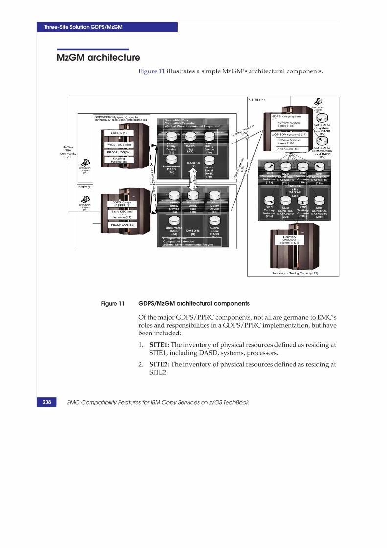
Three-Site Solution GDPS/MzGM
MzGM architecture Figure 11 illustrates a simple MzGM’s architectural components.
Figure 11 GDPS/MzGM architectural components
Of the major GDPS/PPRC components, not all are germane to EMC’s roles and responsibilities in a GDPS/PPRC implementation, but have been included:
1. SITE1: The inventory of physical resources defined as residing atSITE1, including DASD, systems, processors.
2. SITE2: The inventory of physical resources defined as residing atSITE2.
208 EMC Compatibility Features for IBM Copy Services on z/OS TechBook

MzGM architecture
Three-Site Solution GDPS/MzGM
3. GDPS Kp-sys Master K: In addition to the requirements andoperations as the GDPS/PPRC K Master system, this system alsoestablishes an operational relationship with a GDPS/XRC Kx-sys.
4. Other GDPS K systems: Two GDPS/PPRC systems are required(especially if HyperSwap is intended in the architecture).
5. Production systems: Usually the production systems are local toone site, but architectures with higher levels of availability do notrestrict application systems to one site:
a. z/OS systems in the sysplex.
b. Coupling facilities used in the sysplex.
6. GDPS/PPRC sysplex(s): GDPS/PPRC must reside in a sysplex,and GDPS/PRPC can only be in one sysplex. Multiple sysplexesrequire multiple instances of GDPS/PPRC infrastructures.However, in GDPS/MzGM configuration, the GDPS/XRC canmanage multiple GDPS/PPRCs.
7. DASD-A: Traditionally thought of as the primary PPRC DASD,HyperSwap enables an agnostic approach to the situationallocality of “primary” PPRC DASD and primary XRC DASD.GDPS/MzGM is always a concurrent mirroring topology1, theGDPS/PPRC primary and the GDPS/XRC primary volumesreside at the same site.2 This DASD subsystem has all the XRCmicrocode components of sessions, sidefiles, and bitmaps.
a. GDPS/PPRC utility devices for PPRC operations by Ksystems technically can share usage of XRC utility devices (see7e, 8e), but typically the utility devices are dedicated.
b. GDPS local DASD: The DASD used by the GDPS/PPRC Ksystem; not remotely replicated; unused by other systems.
c. Remote Copy DASD, PPRC, and XRC primary volumes. ForHyperSwap, all volumes used by applications and systemsmust be PPRC primary volumes in duplex state. Mostvolumes are continually replicated by XRC, but some
1. Unlike GDDR STAR, which can be designed in a concurrent topology orcascaded topology, GDPS/MzGM must always operate in a concurrenttopology.
2. Some volumes not in PPRC relationships are in XRC relationships.
209

Three-Site Solution GDPS/MzGM
volumes, such as page and temporary volumes, need only occasional XRC replication to establish the infrastructure requirements for recovery systems.
d. Non-PPRCd DASD: Typically the sysplex data sets are usuallyreplicated by XRC on an occasional basis (like 7c).
e. XRC utility devices: MzGM requires XRC utility devices inboth DASD-A and DASD-B.
8. DASD-B: Normally unavailable, this DASD must be able tooperate as the primary PPRC and primary XRC, subsequent to aHyperSwap. After a GDSP/PPRC HyperSwap and GDPS/XRCXSWAP PERFORM, this DASD becomes the primary PPRCsuspended and XRC primary. It has all the XRC components ofsessions, sidefiles and bit maps.
a. GDPS/PPRC utility devices.
b. GDPS local DASD used by the GDPS/PPRC K system.
c. DASD replicated by PPRC and XRC.
d. DASD not replicated by PPRC and usually remote copied onoccasional basis by XRC.
e. XRC utility devices.
9. PPRC cross-site DASD connectivity: Performance, redundancy,and bandwidth suitable for HyperSwap operations.
10. PPRC linkage.
11. BCPii interfaces and components: HMCs, SEs, TCP/IP.connectivity
12. Spare CEC and LPAR: Resources required and capacity onstandby
13. Channel connectivity: SDM’s FICON connectivity to primaryXRC DASD subsystems. Note that HyperSwap and IncrementalResynchronization require simultaneous access by the SDM toboth DASD-A and DASD-B. The architecture and the deploymentof the physical network components depend on the business- continuity requirements of SITE1/SITE2. If SITE1/SITE2 share asingle physical site, and HyperSwap is implemented merely toeliminate the DASD SPOF, then the need for redundant physicalcomponents for FICON access to DASD-A and DASD-B arelessened. If there is geographically significant distance betweenSITE1 and SITE2, significant enough that the business-continuity
210 EMC Compatibility Features for IBM Copy Services on z/OS TechBook
MzGM architecture
Three-Site Solution GDPS/MzGM
expectations are that a mutual failure of SITE1 and SITE2 are not expected, then the need for redundant networking components increases.
a. Connectivity to DASD-A.
b. Connectivity to DASD-B.
14. R-Site Business Continuance Site: Physically, the site ofGDPS/XRC at a remote site.
15. GDPS/XRC Kx-sys: Establishes relationships with one or moreGDPS/PPRC Kp-sys. As is the case with simple GDPS/XRC, theGDPS/XRC K system is responsible for the XRECOVER of thetertiary DASD, and therefore requires access to the DASD-C andDASD-F.
a. GDPS/XRC K system DASD: The local system DASD for theGDPS/K system. Note that it is extremely important to avoidany potential duplicate VOLSERs of the production systems’DASD VOLSERs. Not only would it make it difficult to putonline any intended production primary XRC volumes withthe same VOLSER to the SDMs, but the logical integrity of therecovery set of DASD could be critically impaired if the SDMused these volumes as primary XRC volumes.
16. NetView address space (GDPS/XRC): GDPS runs in the NetView address space. Operation of GDPS/XRC requires logging on toNetView and running GDPS in your operator session.
17. z/OS SDM systems: The z/OS systems that run the XRC SDMs.These are massive z/OS systems running in very large LPARs. Inaddition to running the SDM address spaces, these systemsactually perform the FlashCopy operations. They need access tothe primary DASD, secondary DASD, and the tertiary DASD(DASD-A, DASD-B, DASD-C, and DASD-F).
a. GDPS/XRC SDM system DASD: The local system DASD forthe SDM z/OS systems. Note that it is extremely important toavoid any potential duplicate VOLSERs of the productionsystems’ DASD VOLSERs. Not only would it make it difficultto put online to the SDMs any intended production volumeswith the same VOLSER, if the SDM used these volumes asprimary XRC volumes, the logical integrity of the recovery setof DASD could be critically impaired.
18. SDM address spaces (ANTAS0nn): The SDMs. GDPS/XRC cansupport multiple master sessions all with their own SDMs.
211

Three-Site Solution GDPS/MzGM
19. DASD-C: GDPS/XRC secondary DASD (with FlashCopycapacity the secondary DASD is more than just the XRCsecondary volumes). Just as in simple GDPS/XRC, therelationship between DASD-C and DASD-F is based onFlashCopy source and target. DASD-C and DASD-F must be inthe same Symmetrix. Because MzGM can support multipleGDPS/PPRC to single GDPS/XRC, there can be multipleindependent instances of 21a and 21b.
a. XRC SECONDARY volumes: The volumes used by the SDMsfor mirroring operations. If FlashCopy is employed, thesevolumes are only used for mirroring and never for recovery.
b. SDM control data sets: The SDM control data sets, JOURNAL,STATE, CONTROL, CLUSTER, and MASTER. If FlashCopy isemployed (and it always is), these data sets are FlashCopysources to the “tertiary” control data sets employed by therecovery operations.
20. DASD-F GDPS/XRC tertiary DASD: This is the DASDcomponent used in the DR recovery operations. It is the DASDrecovered for DR testing, and the DASD intended for use byactual DR operations. To recover from the DASD-F, a complete setof XRC secondary volumes and XRC control data sets must beFlashCopyed from DASD-C.
a. XRC Tertiary DASD: The FlashCopy targets and DASDXRECOVER operation employed by the GDPS/XRC Ksystem.
b. SDM control data sets: The FlashCopy targets and controldata sets used by the GDPS/XRC K system for XRECOVER.
21. Recovery production systems: z/OS systems used for recoveryoperations. They should have access to only the DASD-F andonly the XRC tertiary DASD. (FlashCopy targets of the XRCsecondary volumes.)
22. Recovery or testing capacity: Sufficient definition (LPARs)capacity, connectivity, and performance to run production DRoperations.
23. BCPii infrastructure: Interfaces and components, HMCs, SEs,and TCP/IP connectivity.
212 EMC Compatibility Features for IBM Copy Services on z/OS TechBook
MzGM architecture
Three-Site Solution GDPS/MzGM
24. NetView SNA connectivity: Connectivity between theGDPS/XRC K system and each of the GDPS/PPRCinfrastructures. (A single GDPS/XRC can be in a MzGMrelationship with multiple GDPS/PPRCs.)
213

Three-Site Solution GDPS/MzGM
Terminology in GDPS MzGM With so many versions of the DASD and GDPS z/OS systems, a new naming convention has been adopted with GDSP/MzGM infrastructure.
DASD-A: The DASD at GDPS/PPRC Site 1. PPRC mirrored withDASD-B volumes.
DASD-B: The DASD at GDPS/PPRC Site 2. PPRC mirrored withDASD-A volumes.
DASD-C: The DASD at GDPS/XRC site. Traditionally, theGDPS/XRC secondary and FlashCopy sources to the DASD-F,coexists with the DASD-F in the same Symmetrix frame.
DASD-F: The DASD at GDPS/XRC site. Traditionally, theGDPS/XRC tertiary and the FlashCopy targets for the DASD-Ccoexists with the DASD-C in the same Symmetrix frame.
Kp-sys: The GDPS/PPRC K systems.
Kx-sys: The GDPS/XRC K system.
214 EMC Compatibility Features for IBM Copy Services on z/OS TechBook

Three-Site Solution GDPS/MzGM
Symmetrix system compatible feature licensing in GDPS MzGM In addition to other features, Table 13 lists feature order numbers that are typical of an MzGM implementation.
Table 13 MC features for GDPS MzGM implementation
Feature Name Symmetrix System Required/Optional
Compatible Peer Primary Symmetrix DASDSubsystems DASD-A, DASD-B
Required
Compatible Extended Primary Symmetrix DASD Subsystem(s) DASD-A, DASD-B1
Required
Incremental Re-synchronization
Primary Symmetrix DASDSubsystems DASD-A, DASD-B
Only required for GDPS/MzGM implementations, and only when the implementation operates with Incremental Resynchronization (typically employed in MzGM)
Compatible HyperPAV Primary Symmetrix DASDSubsystems DASD-A, DASD-B
Optional (but recommended)
Compatible HyperPAV Secondary Symmetrix DASD Subsystems DASD-C/F
Optional (but recommended)
Compatible Native Flash for Mainframe
Secondary Symmetrix DASD Subsystems DASD-C/F, occasionally on DASD-A and DASD-B
Technically optional, but typically required in GDPS/XRC implementations. Occasionally employed in the GDPS/PPRC DASD Subsystems
1. Reverse site swap, planned return from SITE3 to SITE1 or SITE2 requires licensing of Compatible Extendedfeature on DASD-C/F.
Symmetrix system compatible feature licensing in GDPS MzGM 215

Three-Site Solution GDPS/MzGM
GDPS MzGM and XRC incremental re-synchronization One of the key enabling technologies of MzGM is XRC incremental re-synchronization on the Symmetrix system. XRC suspends after a HyperSwap when the previous PPRC secondary volumes become primary PPRC (suspended) volumes. In order to maintain disaster- recovery preparedness, XRC must resume operations quickly and avoid a complete re-synchronization with the new XRC primary volumes1. GDPS MzGM can be implemented without incremental re-synchronization, but MzGM is rarely implemented without incremental re-synchronization.
Note: GDPS/XRC identifies the HyperSwap volume relationships by querying the current XRC primary/PPRC primary to identify if the volume is in a PPRC mirroring relationship and the PPRC secondary and potential XRC primary.
There is no native XRC Incremental Re-synchronization capability. There are no TSO commands. Incremental Re-synchronization is a GDPS/MzGM-only capability and can only be implemented on DASD subsystems managed by GDPS/MzGM.
Incremental resynchronization feature
GDPS MzGM implementations with incremental resynchronization must have the additional licensed microcode feature of EMC® Compatible Global Mirror Incremental Resync. In addition, the incremental re-synchronization configuration setting must be enabled in the configuration files of all Symmetrix DASD subsystems acting as primary XRC DASD. See “Symmetrix Configuration File Settings for XRC enablement” on page 180 to enable Symmetrix configuration file setting.
Managing incremental resynchronization XRC sessions
In an MzGM implementation, the SDM maintains sessions in both the primary DASD-A and DASD-B through the XRC utility devices on both DASD subsystems. However, only the sessions in one of the
1. A PPRC secondary cannot function as XRC primary, see Table 1,“Allowable Compatible Extended copy combinations,” on page 31.
216 EMC Compatibility Features for IBM Copy Services on z/OS TechBook

GDPS MzGM and XRC incremental re-synchronization
Three-Site Solution GDPS/MzGM
DASD subsystems can actively transfer data at any given time. And after an unplanned HyperSwap, a volume that thinks it is still in an XRC session cannot become a PPRC secondary volume. Consequently, after planned and unplanned HyperSwaps, some activities are required on the GDPS/XRC system to restart both XRC and PPRC.
After a planned or unplanned HyperSwap of the GDPS/PPRC DASD (for instance, DASD-A to DASD-B), GDPS/XRC must reestablish the XRC relationship with the microcode sessions on the DASD-B and start remote copy from DASD-B to DASD-C.
Following an unplanned HyperSwap, there is the potential for unsuspended sessions on the former primary PPRC/primary XRC volumes. Prior to restarting PPRC, these sessions (after resolving the HyperSwap trigger), must be cleaned up from the GDPS/XRC system. GDPS SCRIPT keywords exist for resolving the unsuspended XRC sessions on the Symmetrix system. Only then can GDPS/PPRC restart PPRC remote copy between the DASD-A and DASD-B Symmetrix DASD subsystems.
217

Three-Site Solution GDPS/MzGM
218 EMC Compatibility Features for IBM Copy Services on z/OS TechBook

8
Compatible Native Flash for Mainframe
This chapter includes the following information on Compatible Native Flash (FlashCopy) for Mainframe:
Compatible Native Flash for Mainframe overview ..................220 Description of operation ..................................................................221 Departures from IBM’s solution .....................................................222 FlashCopy components ....................................................................223 FlashCopy modes of operation .......................................................225 FlashCopy Consistency Groups……………………………….….………..227 FlashCopy TSO commands .............................................................229 Symmetrix system configuration file settings.............................230 FlashCopy Considerations with XRC and GDPS/XRC deployment...........………………………………………………………………………233
Compatible Native Flash for Mainframe
219

Compatible Native Flash for Mainframe
Compatible Native Flash for Mainframe overview Compatible Native Flash for Mainframe is a compatible implementation of FlashCopy contained entirely within the Enginuity microcode. It depends upon no external interfaces to emulate FlashCopy operations.
FlashCopy is employed in a number of ways by customers for production applications and imbedded into system applications to create point-in-time copies of volumes and data sets.
A number of applications use it, including DFSMSdss, DFSMShsm, TSO commands, ICKDSF, the ANTRQST interface ,as well as many third-party products.
Additionally, it can play a pivotal role in a GDPS deployment, depending upon the customer’s business availability requirements and the GDPS operation. Employing Compatible Native Flash enables EMC DASD to efficiently interface with these applications.
Employing Compatible Native Flash for Mainframe enables Symmetrix system deployment in solutions where EMC Native point-in-time CLONE and BCV solutions lack the compatibility and ease of use of other DASD vendors. In the case of GDPS, FlashCopy enables EMC Symmetrix DASD subsystems to fully integrate with GDPS GEOPARM FlashCopy relationships, FlashCopy panel operations, and FlashCopy SCRIPT directives.
220 EMC Compatibility Features for IBM Copy Services on z/OS TechBook

Description of operation
Compatible Native Flash for Mainframe
Description of operation FlashCopy is a copy relationship between two volumes in a single Symmetrix DASD subsystem1. A microcode session manages the images of the two volumes (source volume and the image of the target volume) and the copy operation.
1. Early versions of IBM FlashCopy limited the volume relationship tovolumes within a single LCU. This restriction no longer exists, but insome environments its legacy can still be encountered.
221

Compatible Native Flash for Mainframe
Departures from IBM’s solution Consider the following departures listed in this section.
Supported FlashCopy functions
Not all FlashCopy features are supported. Notably, FBA devices, Inband FlashCopy, the imbedded FlashCopy in Global Mirror, and Space Efficient FlashCopy are not supported. Although Space Efficient FlashCopy is not supported, an equivalent capability is provided by defining the target devices to a thin pool and using the NOCOPY option.
Symmetrix split considerations
Volumes involved in a FlashCopy relationship must be contained within the same Symmetrix split.
A Symmetrix split is defined as a virtual frame located within the Symmetrix physical configuration. At the time of this writing, up to 16 splits can currently be defined via configuration tools within each Symmetrix VMAX physical frame.
222 EMC Compatibility Features for IBM Copy Services on z/OS TechBook

FlashCopy components
Compatible Native Flash for Mainframe
FlashCopy components This section briefly describes FlashCopy components.
Figure 12 FlashCopy Components
Source volume
Source volumes are typically ONLINE, especially in a GDPS implementation.
223
Compatible Native Flash for Mainframe
Target volume
Target volumes are typically OFFLINE to all systems at FlashCopy initiation.
The target and source volume must be in the same Symmetrix DASD subsystem and same subsystem split.
The target volume must be of equal or greater capacity than the source volume.
FlashCopy session
A microcode FlashCopy session is created by a FlashCopy FCESTABLISH directive. It immediately establishes the relationship between the volumes and enables normal access to the volumes. Depending on the mode of operation, tracks may be copied in the background or not, and sessions may have finite duration (FlashCopy COPY) or indeterminate duration (FlashCopy NOCOPY).
Typically, a FlashCopy session must be withdrawn before another can be established. It is not uncommon to find logic in GDPS scripts that ensures that FlashCopy sessions are withdrawn prior to their intended establishment.
224 EMC Compatibility Features for IBM Copy Services on z/OS TechBook
FlashCopy modes of operation
Compatible Native Flash for Mainframe
FlashCopy modes of operation Traditional FlashCopy is a point-in-time copy. When the FlashCopy is initiated, a session starts on DASD subsystem and its function is to establish the perception that there are immediately two copies of the data. It manages the access to the two versions of the data (the source and target volumes) and copies the tracks from the source volume to the target volume. There are two modes of operation. A FlashCopy COPY operation copies the tracks in the background until there are two physically complete copies of the data. A FlashCopy NOCOPY operation copies only the tracks required to preserve the perception that there are two distinct copies of data.
In the case of GDPS/XRC, the instantiation of the tertiary DASD for DR testing may be accomplished with a FlashCopy NOCOPY, but actual DR should employ a FlashCopy COPY.
The following modes of operation are briefly described in this section:
“FlashCopy COPY” on page 225
“FlashCopy NOCOPY” on page 226
“FlashCopy INCREMENTAL” on page 226
FlashCopy COPY
A FlashCopy COPY session copies all tracks from the source to the target volume. When all source tracks are copied to the target volume, the session ends. When the copy operation is complete the target volume is a physically complete copy.
While the source volume is being copied, reads to the target volume can be satisfied either from the source volume or the target volume, depending on whether the track has been copied.
Writes to the source volume get special handling depending upon whether the track being updated has already been copied to the FlashCopy target volume. If the track has already been copied by FlashCopy, then the write to the target volume is processed unabated. However, if the track has not been copied, before the source track can be updated the microcode session must read the track from the source, write the track to the target, and then update the source. This operation can significantly increase write I/O response time and degrade performance. This is known as delay on first write.
225

Compatible Native Flash for Mainframe
Reads to the source volume are unaffected by the FlashCopy relationship. Writes to the target volume are unaffected, except when the track has not yet been copied from the source. In that case, a background copy is performed, and the target write is then allowed to proceed.
FlashCopy NOCOPY
A FlashCopy NOCOPY session copies tracks only when an initial update to the source volume track dictates that the track must first be read from the source. It writes the track to the target volume, and then allows the write to the source volume. As in the case of FlashCopy COPY delay on first write, this operation can significantly impact production write performance. However, unlike the COPY mode, there exists no background copy task, so the FlashCopy session persists until such time as all the tracks are updated or the FlashCopy session is withdrawn by a FCWITHDR directive.
FlashCopy NOCOPY can be converted to COPY by a NOCOPY2COPY directive.
FlashCopy INCREMENTAL
FlashCopy INCREMENTAL can be thought of as a combination of an initial FlashCopy COPY to create a full copy and subsequent incremental FlashCopy operations to copy only the changed tracks since the previous FlashCopy.
226 EMC Compatibility Features for IBM Copy Services on z/OS TechBook

FlashCopy Consistency Groups
Compatible Native Flash for Mainframe
FlashCopy Consistency Groups Compatible Native FlashCopy supports FlashCopy consistency groups. This feature enables the creation of write dependent consistent sets of FlashCopy target volumes through application directed formation of FlashCopy operations utilizing the FCESTABLISH ACTION(FREEZE) operand to queisce application updates. The typical operation is
1. Issue FlashCopy FCESTABLISH with the FREEZE option tocreate a FlashCopy consistency group. This simultaneouslyperforms three operations: 1) it starts the FlashCopy sessionsbetween the source and target, 2) the FlashCopy source volumesare put in "long busy" to suspend updates to the source volumeand 3) the FlashCopy consistency timer starts.
2. Some set of operations to create, this can include normalFlashCopy operations.
3. Issue FlashCopy FCWITHDRAW with THAW to cancel the freezeto the primary volumes. This special form of the FCWITHDRAWonly removes the "long busy" and does not cancel the FlashCopysession between the FlashCopy source and target. If a THAW isnot issued before the FlashCopy consistency timer expires theconsistency group thaws.
Review the section Symmetrix system configuration file settings 230 for Symmetrix Configuration file settings that manage FlashCopy Freeze.
Difference with FlashCopy consistency bears some commonality with PPRC PPRC CGROUP CGROUP operations but has important differences.
The PPRC CGROUP affects writes to all the volume pairs in theLCU. FlashCopy Freeze/Thaw only prevents write operations tothe FlashCopy source volume by putting up long busy on thatvolume only.
FlashCopy Freeze shares the same time setting as PPRCCGROUP’s timer. But each FlashCopy freeze source volume hasits own timer.
FlashCopy CGROUPs are application based and bounded byapplication operation.
227
Compatible Native Flash for Mainframe
Multiple FREEZEs can be issued for volumes in a single LCU, buta single FCWITHDRAW THAW to a FlashCopy session thaws allFlashCopy source volumes in "long busy".
FlashCopy The FlashCopy session established with a FCESTABLISH ACTION Consistency Group (FREEZE)
FlashCopy Freeze FlashCopy freeze is established using the optional ACTION parameter on the FCESTABLISH command. It results in a long busy on the source volume. The freeze is removed by a subsequent FCWITHDR ACTION(THAW) or expiration of the freeze by the PPRC/FlashCopy Consistency Timer.
FlashCopy Thaw FlashCopy thaw is accomplished using the optional ACTION parameter on the FCWITHDR command. It removes the long busy on all source volumes in that source volume LCU. If the PPRC/FlashCopy Consistency Timer expires it only removes the freeze on the source volume.
228 EMC Compatibility Features for IBM Copy Services on z/OS TechBook

Compatible Native Flash for Mainframe
FlashCopy TSO commands Table 14 lists FlashCopy TSO commands.
Table 14 FlashCopy commands
TSOcommand Purpose Primary volume
Secondary volume
FCESTABL Establishes FlashCopy session between a pair of volumes ONLINE OFFLINE
FCQUERY Query the FlashCopy status
FCWITHDR Withdraws a FlashCopy session
FlashCopy TSO commands 229

ation file settings g are options in the Symmetrix configuration file to atible Native Flash:
nfiguration File Settings for FlashCopy enablement
Name Value Description
CKD->impl_fix_part->PPRC/ FlashCopy consistency
YES | No YESis required for enablement of FlashCopy consistency Groups with FlashCopy freeze/thaw. This isrequiredfor employment ofzero suspend FlashCopy technology with XRC.
CKD->impl_fix_part->PPRC/ FlashCopy consistency timer
0:65535 seconds Sets the maximumduration of a freeze before subsystem automaticallyraisesthelongbusy on the freeze volumes. 180 seconds is the default when 0 is specified. Note that this time should always begreater than the zero suspend FlashCopy timeout parameter (Z parameter) setting.
CKD->Enable FlashCopy YES | NO SpecifyYES to enable FlashCopy
CKD->Enable Remote FlashCopy YES | NO SpecifyYES to enable Remote Pair FlashCopy feature
Services on z/OS TechBook
Compatible Native Flash for Mainframe
Symmetrix system configurThe followin enable Comp
Table 15 Symmetrix Co
230 EMC Compatibility Features for IBM Copy

FlashCopy with GDPS/PPRC deployment
Compatible Native Flash for Mainframe
FlashCopy with GDPS/PPRC deployment FlashCopy has a long history of employment with GDPS/PPRC. Traditionally as a mechanism to address single points of failure during re-synchronization and testing. More recently FlashCopy operations have been enhanced to support application requirements without adversely affecting HyperSwap capability through the Remote Pair FlashCopy capability.
GDPS Managed FlashCopy
See Section “FlashCopy with GDPS/PPRC” on page 108 for details on GDPS/PPRC managed FlashCopy.
Remote Pair FlashCopy
Previously creating application based FlashCopy pairs of PPRC primary and PPRC secondary volumes were problematic, especially in GDPS/PPRC implementations with HyperSwap for several reasons. The problem is especially noticeable for application based FlashCopy of primary/secondary volumes and not GDPS/PPRC managed FlashCopy. A central expectation is that the invitation of a FlashCopy between primary PPRC volumes at SITE1 initiate a similar relationship between secondary PPRC volumes at SITE2.
1. Create and manage the FlashCopy session simultaneouslybetween primary volumes and their secondary volumes.
2. Maintain PPRC duplex status between PPRC pairs allowingHyperSwap to remain enabled.
3. FlashCopy replication is independent of PPRC linkage.
The new feature support on Symmetrix Remote Pair FlashCopy addresses many of these concerns.
The following diagram illustrates the relationship between the PPRC and FlashCopy relationships between a pair of PPRC volumes.
231
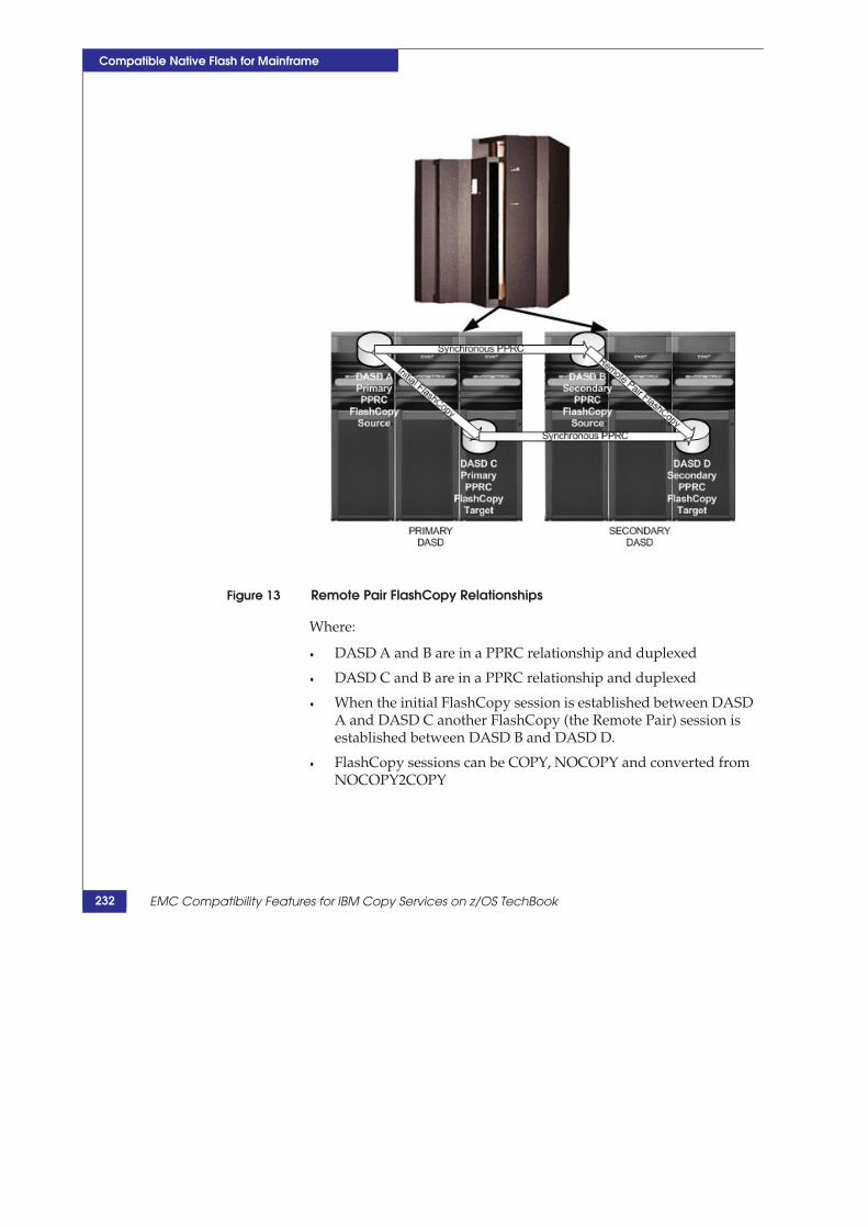
Compatible Native Flash for Mainframe
Figure 13 Remote Pair FlashCopy Relationships
Where:
DASD A and B are in a PPRC relationship and duplexed
DASD C and B are in a PPRC relationship and duplexed
When the initial FlashCopy session is established between DASDA and DASD C another FlashCopy (the Remote Pair) session isestablished between DASD B and DASD D.
FlashCopy sessions can be COPY, NOCOPY and converted fromNOCOPY2COPY
232 EMC Compatibility Features for IBM Copy Services on z/OS TechBook

FlashCopy Considerations with XRC and GDPS/XRC deployment
Compatible Native Flash for Mainframe
FlashCopy Considerations with XRC and GDPS/XRC deployment To recover from a tertiary DASD component, all the XRC DASD (secondary volumes and XRC control data sets) must be flashed in a time consistent manner. While some other techniques have been published for manual recovery of XRC on FlashCopy, the following techniques are the most widely adopted.
This section includes the following information:
“Traditional DR testing without Zero Suspend FlashCopy” on page 233
“DR Testing with Zero Suspend FlashCopy” on page 233
“Recovery for actual DR” on page 235
“Additional FlashCopy considerations ” on page 236
“FlashCopy and XRC performance concerns during DR testing” on page 237
Traditional DR testing without Zero Suspend FlashCopy
Traditionally, this is accomplished either using TSO commands or a GDPS/XRC SCRIPT to::
Ensure tertiary DASD is offline to all systems
Withdraw any old FlashCopy sessions
XSUSPEND XRC
FlashCopy all secondary DASD to the tertiary DASD
STARTSECONDARY to restart XRC mirroring
XRC XRECOVER the tertiary DASD from the GDPS K system
Wait for XRC to duplex
Start up DR test workload
DR Testing with Zero Suspend FlashCopy
More recently IBM has delivered a Zero Suspend FlashCopy1 utility and for XRC to enable the creation of a test copy of recovered DASD without requiring the suspension of the XRC SDMs. Zero Suspend FlashCopy is technically not an XRC feature. Rather, it is a specific
233
Compatible Native Flash for Mainframe
use of FlashCopy FREEZE/THAW technology in an XRC environment using the Zero Suspend FlashCopy batch JCL operation or GDPS/XRC SCRIPT FC0SUSPEND operand.
Employing GDPS/XRC’s FC0SUSPEND SCRIPT command also requires updating the GEOXPARM FC0type specification on XRC statements.
Compatible Native Flash provides transparent definition and operation of Zero Suspend FlashCopy.
Zero Suspend FlashCopy technology does depend upon some XRC SDM internal operations, and not all operations are immediately obvious:
By using FlashCopy freeze/thaw feature it prevents writes of anSDM’s Consistency Groups to the SDM’s Control data set and indoing so stop the recording of the SDM’s Consistency Groups tothe JOURNAL data sets. These volumes containing the SDMControl data sets must be identified in the XRC GEOPARMsettings.
Once FlashCopy sessions have been initiated for all the freezevolumes, Zero Suspend FlashCopy performs a FlashCopy of allXRC secondary volumes and SDM control data sets (includingJournal data sets) to the tertiary volumes. No time consistency ofthe secondary DASD is assumed, and writes of consistencygroups queued for write to the secondary DASD continueunabated without any regard for consistency.
Once FlashCopy sessions have been initiated for all the SDMcontrol data sets and all secondary/tertiary volumes, the zerosuspend FlashCopy utility thaws the freeze on the SDM Controldata set volume(s).
Later, normal SDM XRECOVER operations directed against thetertiary DASD (target volumes of the Zero Suspend FlashCopy)reads all valid XRC Consistency Groups from the tertiaryJOURNALs and then rewrite these CGs to the tertiary DASD.Consequently, any inconsistencies of write dependencies thatresulted from the Zero Suspend FlashCopy operations areoverwritten by consistent data during normal XRECOVERoperations.
1. Zero Suspend FlashCopy was originally delivered as a batch programand can still be used as such outside of GDPS/XRC operations.
234 EMC Compatibility Features for IBM Copy Services on z/OS TechBook

FlashCopy Considerations with XRC and GDPS/XRC deployment
Compatible Native Flash for Mainframe
The SCRIPT pseudo-code for a DR testing:
Optionally withdraw any existing FlashCopy sessions or use theZero Suspend FlashCopy operand.
Make sure that the tertiary DASD is offline on all systems
FC0SUSPEND XRC (optionally employ FCWITHDR operand)
Put the tertiary DASD online to the K system
XRC XRECOVER the tertiary DASD from the GDPS K system
Start up DR test workload
Zero suspend FlashCopy not only reduces the number of steps required for DR testing, but it also eliminates XRC suspension, preserving duplex status for all remote copy pairs.
Recovery for actual DR
“Test the way you run; run the way you test.”
XRC has no failover/failback capability. In addition, testing with GDPS/XRC usually employs tertiary DASD, which results in the use of tertiary DASD as the recovery DASD during failover, leaving the secondary DASD as a gold copy.
Actual disaster- recovery operations Pseudo-code for a script to perform actual DR recovery:
Shut down the SDM z/OS systems
Withdraw any existing FlashCopy sessions
FlashCopy all secondary to tertiary DASD (note that thewithdraw and FlashCopy operations can be combined if theGDPS/XRC Zero Suspend FlashCopy script command isemployed).
XRC XRECOVER the tertiary DASD from the K system
Restart the production workload
Always ensure that the FlashCopy session creating the tertiary DASD is a FlashCopy COPY (either by specifying the FCESTABLISH with COPY, or subsequently, with a NOCOPY2COPY option). The integrity of the recovered DASD is entirely dependent upon the operation of the FlashCopy microcode session. If those sessions are eliminated by a FCWITHDR, then all data updated since the beginning of the disaster recovery operation would be lost. An actual
235

Compatible Native Flash for Mainframe
DR would not experience delay on first write SDM impact to the secondary DASD. Consequently, performance concerns are lessened.
Additional FlashCopy considerations
Additional details for these scripting techniques when operatingXRC through GDPS/XRC can be found in the GDPS/XRCInstallation and Customization Guide. Review these guidelines priorto implementation. In consideration of brevity, a considerablenumber of storage management operations to vary offline/onlineand FlashCopy clean up have been removed.
Recovery techniques employing GDPS/XRC tertiary DASDrequires specific GRS updates that can be found in theGDPS/XRC Guide and must be employed. An XRC XRECOVERactually restarts the SDM address space. The SDM protects itselffrom multiple instances through ENQ/DEQ of resources basedon the SDM name, which under normal circumstances wouldprevent XRECOVER operations on the GDPS K system duringnormal XRC operations by the SDM on the SDM z/OS system (allGDPS/XRC systems being in a sysplex). However, throughmodification of the GRSRNL specifications, it is possible tochange the SDM’s ENQ/DEQ from GLOBAL to LOCAL. With therecognition that GDPS SCRIPT operations provide operationalcontrol of the SDM and manage the resource control equivalenceto ENQ/DEQ.
Recovery from tertiary DASD requires that FlashCopy targetsmust be defined for all XRC secondary volumes, as well as allXRC control data set volumes. This requires special definition oftertiary volumes for the control data sets in the XRC GEOPARM.The SDM control data sets must be on these volumes.
Zero Suspend FlashCopy requires additional GEOXPARMspecifications to prevent updates on the control data sets throughFlashCopy FREEZE.
Documented in the GDPS Installation Guide are very specificrecommendations on the IOCDS definitions for SDM systems,GDPS K systems, and the recovery systems. GDPS Operations,GDPS Scripting, and recovery operations have specificexpectations regarding device access.
236 EMC Compatibility Features for IBM Copy Services on z/OS TechBook

FlashCopy Considerations with XRC and GDPS/XRC deployment
Compatible Native Flash for Mainframe
Use good coding techniques to ensure that the FlashCopy andXRECOVER scripts work successfully. The scripts should assumenothing about the initial conditions. Add initialization logic to theSCRIPTs to ensure that the tertiary volumes are offline to allsystems, and FCWITHDRAW all FlashCopy sessions.
FlashCopy and XRC performance concerns during DR testing
FlashCopy is frequently invoked as traditional FlashCopy COPY during DR testing. As intellectually appealing as NOCOPY appears on first consideration, operational experience with XRC shows it is somewhat counter-indicated. FlashCopy operates quickly because the FlashCopy initially establishes a session between the source and target volumes, and tracks are subsequently copied. If FlashCopy is invoked with the COPY option, the microcode sessions copy all the tracks from the source volume to target volume as a background operation. If FlashCopy is invoked with the NOCOPY option the microcode sessions only copy tracks as needed. Compatible Native Flash copies updated tracks on first write, that is, a write to the source volume of a track not as yet copied to the target forces an immediate copy1, with some elongation of the I/O operation. Delay on first write has performance implications during DR testing by significantly slowing the SDM’s writes to secondary volumes, and to a lesser extent, writes to the control data sets. Write operations against the tertiary DASD are significantly impacted, particularly to the XRC secondary volumes where a consistency group may contain multiple write updates to a single volume.
As each write is potentially impacted by the delay, all the writes of a consistency group (writes to consistency groups must complete serially) can be significantly delayed. Not infrequently, CG write performance to the secondary DASD can impact entire SDM operations, causing CGs to queue for write to secondary, exhausting the z/OS buffers in the SDM. This results in reader pacing as the readers’ access to buffers is limited and allows residuals to accumulate on the Symmetrix sidefile. This results in write pacing,
1. The FlashCopy microcode session must read the referenced track from the source track (GDPS/XRC secondary DASD volume), write it to the targettrack (GDPS/XRC tertiary DASD volume), and then allow the write to the source volume, with significant penalty to the read or write I/O operation (almost always a write operation against the XRC secondary DASD).
237

Compatible Native Flash for Mainframe
elongation of RPO, and under the worst of conditions, suspension of the SDM as the sidefile resources are exhausted.
238 EMC Compatibility Features for IBM Copy Services on z/OS TechBook

A
PPRC PATHing and Linkage Address
This appendix contains the following information:
Link parameters ................................................................................ 240
PPRC PATHing and Linkage Address 239

PPRC PATHing and Linkage Address
Link parameters Linkage format used in the TSO CESTPATH commands, ICKDSF PPRCOPY ESTPATH commands, and GEOPARM LINK statements are unique to EMC Symmetrix systems. Despite actually employing Fiber Channel protocol and technology, one must employ an ESCON type of path address as the link parameter1. The port numbering scheme is unique to Symmetrix systems.
Link parameters for VMAX 20K and 40K
The link parameters (also frequently documented as linkaddr) of the CESTPATH (ICKDSF PPRCOPY, and GEOPARM MIRROR), describes the pathing over the physical linkage between a primary LCU and secondary LCU by establishing which physical paths are employed for mirroring by volumes in the LCUs. In native PPRC, the pathing between LCUs is defined through the CESTPATH command. Additionally, CGROUP operations are also established for the mirrored volumes. In GDPS’s GEOPARM definitions, the linkaddr of the SITE1 and SITE2 statements in the GEOPLEX LINKS section performs the same function. A PPRC path between two LCUs has between one and eight physical links.
A link parameter is composed of four fields (eight hex digits: AABBCCDD), where
AA: Is two hex digits of the sending side (PRIMARY DASD)SRDF director (00-7F). See Table 16 on page 241.
BB: Is two hex digits of the receiving side (SECONDARY DASD)SRDF director (00-7F). See Table 16 on page 241.
CC: Is two hex digits of the SRDF DEVICE GROUP (X’00’-X’3F’),which are set in the configuration file.
DD: Is two hex digits of the sending LCU IMAGE (X’00’-X’7F’)(LCU) that are established in IOGEN.
1. WWNN is not supported .
240 EMC Compatibility Features for IBM Copy Services on z/OS TechBook

PPRC PATHing and Linkage Address
Table 16 Symmetrix PPRC link parameter director map hex lookup
Dir a 1 2 3 4 5 6 7 8 9 10 11 12 13 14 15 16
Modelb PROC
VM
AX
H 70 71 72 73 74 75 76 77 78 79 7A 7B 7C 7D 7E 7F
G 60 61 62 63 64 65 66 67 68 69 6A 6B 6C 6D 6E 6F
F 50 51 52 53 54 55 56 57 58 59 5A 5B 5C 5D 5E 5F
E 40 41 42 43 44 45 46 47 48 49 4A 4B 4C 4D 4E 4F
DM
X
D 30 31 32 33 34 35 36 37 38 39 3A 3B 3C 3D 3E 3F
C 20 21 22 23 24 25 26 27 28 29 2A 2B 2C 2D 2E 2F
B 10 11 12 13 14 15 16 17 18 19 1A 1B 1C 1D 1E 1F
A 00 01 02 03 04 05 06 07 08 09 0A 0B 0C 0D 0E 0F
a. Relative to 1, note that HOSTCOMPONENTreports director slots relative to 0.
b. Note that DMX has only four processor interfaces on a director and VMAX have eight processor interface
For example, if a physical link connects director slot 5 processor B to director slot 6 processor C, and the SRDF GROUP is x 03 in CU image 00, then the linkaddr is: 14250300. This is repeated for as many physical links exist and are required to describe the pathing between two LCUs. (Compatible Peer's emulation of PPRC's logical paths works best when the links for a SRDF GROUP as defined in the Symmetrix configuration file are in agreement with PPRC's CESTPATH definition.) The pathing is repeated for as many LCU pairs as required. Note that the physical links between LCU pairs are usually shared by as many LCUs pairs as required.
Good sources of information for the GEOPARM-specific Symmetrix hardware and Configuration File settings are the ProcGEN II report and CheckUpgrade.dat report.
Link parameters 241

PPRC PATHing and Linkage Address
The RDF_Directors, and which SRDF_Groups use those directors, are found in CheckUpgrade.dat. The directors can be confirmed by reviewing the "Director and Memory Layout" section in the ProcGen II report. The RA ports are the SRDF links.
Defining PPRC PATHs with ICKDSF
When using ICKDSF to manage Compatible Peer on VMAX systems, use the LINK parameter with EMC-specific link specifications instead of the FCPPATH and WWNN parameters.
For example:
PPRCOPY ESTPATH UNIT(1C00) AON - PRI(X'2960',AAGAG) - SEC(X'2971',AAFTR) - LSS(X'00',X'01') -
LINK(X'46460001',X'47470001',X'56560001',X'57570001')
Link Parameters for VMAX3 and VMAX All Flash
Due to the enhanced port architecture of Symmetrix VMAX3 system technology, the Link Address for these systems is not only remains unique, but must be unique to even legacy Symmetrix system Link Address syntax.
The format of the Link Address requires information related to port numbering as well as SRDF director numbering. It also requires the current (or planned) SRDF Group number, which is allowed to be different at each side but for ease of manageability is typically the same at each side. For each Link Address the Symmetrix director, port, and SRDF Group information relating to the system at each side of the SRDF connection is required.
Note: In order to support Hyperswap and failover/failback, Link Address’ describing PPRC paths in both directions should be provided and coded in advance
242 EMC Compatibility Features for IBM Copy Services on z/OS TechBook

PPRC PATHing and Linkage Address
243
In order to support PPRC via SRDF connection from VMAX3 to legacy VMAX1-2, the format of the Link Address is now divided into two halves. The first (two byte) half describes the SRDF connection for the primary side system and the second (two byte) half describes the SRDF connection for the secondary side system.
Internal parameter definitions no longer always fall into whole digit definitions. Rather, the two bytes describing each half of the SRDF connection for the Link Address have bit level significance. For each Symmetrix system type participating in an SRDF relationship with a VMAX3, the breakdown is as follows:
VMAX3:
4 bits for SRDF board (up to 16 boards, 0-F)
1 bit pad
5 bits for SRDF port
6 bits for this side SRDF Group number (00 – 3F hex, zero based)
VMAX 20K, 40K:
1 byte for SRDF director (see Table 15)
2 bits pad
6 bits for this side SRDF Group number (00 – 3F hex, zero based)
Your EMC Field Representative has access to tools that will define proper Link Address parameters for your installation. As well, your EMC Field Service Representative has access to tools that will create, modify, or delete SRDF Groups if no EMC SRDF software is employed at your site. SRDF Groups are no longer configured with the Symmetrix configuration file with Symmetrix VMAX3 systems.
One major advantage to this new format is that the secondary CU image number is no longer required. As such, many less Link Address’ need to be defined overall where multiple LCUs are defined within each Symmetrix participating in the SRDF connection.
Prior to creating SRDF Groups and PPRC paths between VMAX3 and VMAX1-2 systems, each system must be running the appropriate Enginuity level providing support. Consult with your EMC Field Service Representative for more detail.
Link parameters

PPRC PATHing and Linkage Address
244 EMC Compatibility Features for IBM Copy Services on z/OS TechBook

B
EMC’s Role as a GDPS Storage Vendor
This appendix contains the following information:
New GDPS deployment ................................................................... 246 Supplementing an existing GDPS implementation ...................... 248
EMC’s Role as a GDPS Storage Vendor 245

EMC’s Role as a GDPS Storage Vendor
New GDPS deployment EMC does not license or sell GDPS. EMC’s role in a GDPS implementation is as a storage vendor. Even in that limited role EMC must still understand the customer’s business-continuity requirements and the architectural requirements of intended GDPS deployment topology:
Which products are being deployed, such as GDPS/PPRC,GDPS/HM, or GDPS MzGM?
What are the autonomic policies for FREEZE and SWAP?
What is the operational topology?
What are the business-continuity expectations and how willGDPS be implemented and operated to achieve those goals?
What are the appropriate features, such as Compatible PEER(PPRC) and possibly Native z/OS Flash (FlashCopy)?
Participation as a designated storage vendor in GDPS Deployment Workshops (often part of GDPS implementation by IBM Global Services,) should be anticipated. This is usually a detailed project planning session with the customer and GDPS implementation teams. As the storage vendor, EMC commits to project deliverables and comments on the following topics:
Storage solution design, licensing, and implementation consistentwith customer’s requirements (primary DASD, secondary DASD,FlashCopy deployment when required).
Required compatible licensing components for the architecture(Compatible PEER, Compatible z/OS Flash).
Performance recommendations and cabling requirements.
Storage deployment activities.
Symmetrix Configuration settings to enable Compatible Peer andCompatible Native Clone.
Enginuity microcode maintenance levels.
Understand and provide consulting services for HCD definitionfor the production, GDPS K systems, and recovery systemsconsistent with the operation of GDPS.
Possible data migration strategies with z/OS Migrator orequivalent product.
246 EMC Compatibility Features for IBM Copy Services on z/OS TechBook

New GDPS deployment
EMC’s Role as a GDPS Storage Vendor
Consulting on GEOPARM definitions, volume specifications, andlinkaddr definitions.
LCU design, including GDPS/PPRC Utility Volume designation.
Construction of non-PPRC storage resources (K systems and nonmirrored storage).
Participate in development of GDPS remote copy SCRIPTs.
Participate in testing activities.
In HyperSwap implementations, planned and unplannedactivities to validate HyperSwap timing and its effect onapplication stability.
247

EMC’s Role as a GDPS Storage Vendor
Supplementing an existing GDPS implementation Because GDPS is a licensed offering and not a product, storage augmentations of existing GDPS deployments are often undertaken without IBM Global Services’ direct involvement. Typically, the customer is more experienced than an initial GDPS deployment, but lacking IBM Global Services’ direct involvement, more responsibility and direction might be expected from EMC.
Before proposing a configuration, understand the existing GDPS deployment and the requirements for our implementation. Scope out not only the hardware and microcode requirements, but also the services component and any potential changes in the customer’s business-continuity requirements or operations.
Configuration and licensing of solutions consistent with existingGDPS goals and conventions employed by the customer.
Performance consulting and validation.
Storage deployment activities.
Symmetrix configuration settings for Compatible Peer andCompatible Native Flash.
Cabling.
Understand and provide consulting services for HCD definition.
Possible data migration with products consistent with GDPSoperations and continuous availability.
Participate in solution testing.
In HyperSwap implementations, participate in timing validation.
248 EMC Compatibility Features for IBM Copy Services on z/OS TechBook

C
Sample GEOPARM (GEOXPARM)
This appendix contains the following information:
Overview ............................................................................................ 250 GDPS/PPRC GEOPARM ...................................................................... 251
Sample GEOPARM (GEOXPARM) 249

Sample GEOPARM (GEOXPARM)
Overview Sample GDPS/PPRC and GDPS/XRC GEOPARMs are included for illustration purposes only and would require extensive modification at an actual customer implementation.
Note the differences in GEOPARM syntax between GDPS/PPRC and GDPS/XRC.
250 EMC Compatibility Features for IBM Copy Services on z/OS TechBook

GDPS/PPRC GEOPARM
Sample GEOPARM (GEOXPARM)
GDPS/PPRC GEOPARM The following is an example of an actual GDPS/PPRC GEOPARM for Compatible Peer on a VMAX array.
GEOPLEX LINKS ************************************************************************* * Note the unique linkaddr composition indicative of EMC VMAX* Physical links are shared among all the LCU pairs, ports 38 into 38,* 28 into 28, 18 into 18, 08 into 08, 39 into 39, 29, into 29, 19* into 19, 09 into 09.* Note the SITE1 to SITE2 symmetry (indicative of HyperSwap* Note how the LCU pairs increase through the SITEn statements* Note as well the “NE” specification consistent with EMC Symmetrix* protocol definition.* Note the convention for GEOPARM SITE1/SITE2 statement continuation* *************************************************************************
SITE1='2E41,2D41,Y,NE,38380001,28280001,18180001,08080001,39390001,C' 29290001,19190001,09090001’
SITE2='2D41,2E41,Y,NE,38380001,28280001,18180001,08080001,39390001,C' 29290001,19190001,09090001’
SITE1='2E42,2D42,Y,NE,38380002,28280002,18180002,08080002,39390002,C' 29290002,19190002,09090002’
SITE2='2D42,2E42,Y,NE,38380002,28280002,18180002,08080002,39390002,C' 29290002,19190002,09090002’
SITE1='2E43,2D43,Y,NE,38380003,28280003,18180003,08080003,39390003,C' 29290003,19190003,09090003’
SITE2='2D43,2E43,Y,NE,38380003,28280003,18180003,08080003,39390003,C' 29290003,19190003,09090003’
SITE1='2E44,2D44,Y,NE,38380004,28280004,18180004,08080004,39390004,C' 29290004,19190004,09090004’
SITE2='2D44,2E44,Y,NE,38380004,28280004,18180004,08080004,39390004,C' 29290004,19190004,09090004’
SITE1='2E45,2D45,Y,NE,38380005,28280005,18180005,08080005,39390005,C' 29290005,19190005,09090005’
SITE2='2D45,2E45,Y,NE,38380005,28280005,18180005,08080005,39390005,C' 29290005,19190005,09090005’
SITE1=‘2E46,2D46,Y,NE,38380006,28280006,18180006,08080006,39390006,C' 29290006,19190006,09090006’
SITE2='2D46,2E46,Y,NE,38380006,28280006,18180006,08080006,39390006,C' 29290006,19190006,09090006’
SITE1=‘2E47,2D47,Y,NE,38380007,28280007,18180007,08080007,39390007,C' 29290007,19190007,09090007’
SITE2='2D47,2E47,Y,NE,38380007,28280007,18180007,08080007,39390007,C' 29290007,19190007,09090007’
SITE1=‘2E48,2D48,Y,NE,38380008,28280008,18180008,08080008,39390008,C 29290008,19190008,09090008’
SITE2='2D48,2E48,Y,NE,38380008,28280008,18180008,08080008,39390008,C' 29290008,19190008,09090008’
251
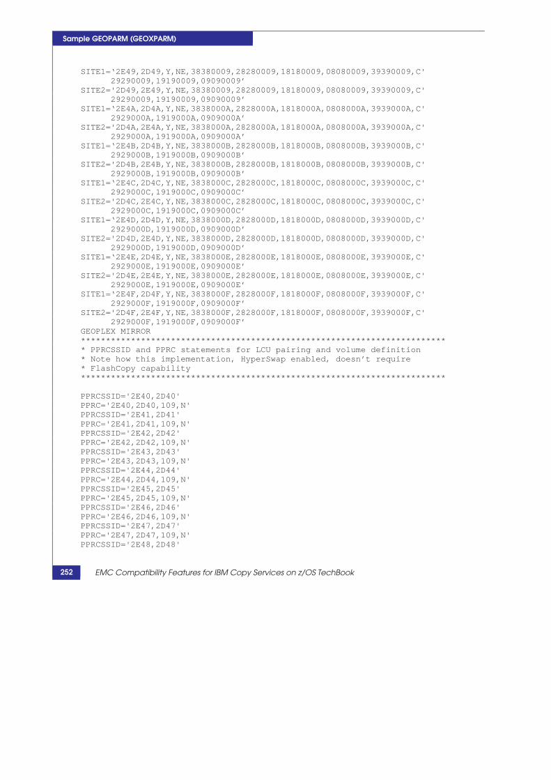
Sample GEOPARM (GEOXPARM)
SITE1=‘2E49,2D49,Y,NE,38380009,28280009,18180009,08080009,39390009,C' 29290009,19190009,09090009’
SITE2='2D49,2E49,Y,NE,38380009,28280009,18180009,08080009,39390009,C' 29290009,19190009,09090009’
SITE1=‘2E4A,2D4A,Y,NE,3838000A,2828000A,1818000A,0808000A,3939000A,C' 2929000A,1919000A,0909000A’
SITE2='2D4A,2E4A,Y,NE,3838000A,2828000A,1818000A,0808000A,3939000A,C' 2929000A,1919000A,0909000A’
SITE1=‘2E4B,2D4B,Y,NE,3838000B,2828000B,1818000B,0808000B,3939000B,C' 2929000B,1919000B,0909000B’
SITE2='2D4B,2E4B,Y,NE,3838000B,2828000B,1818000B,0808000B,3939000B,C' 2929000B,1919000B,0909000B’
SITE1=‘2E4C,2D4C,Y,NE,3838000C,2828000C,1818000C,0808000C,3939000C,C' 2929000C,1919000C,0909000C’
SITE2='2D4C,2E4C,Y,NE,3838000C,2828000C,1818000C,0808000C,3939000C,C' 2929000C,1919000C,0909000C’
SITE1=‘2E4D,2D4D,Y,NE,3838000D,2828000D,1818000D,0808000D,3939000D,C' 2929000D,1919000D,0909000D’
SITE2='2D4D,2E4D,Y,NE,3838000D,2828000D,1818000D,0808000D,3939000D,C' 2929000D,1919000D,0909000D’
SITE1=‘2E4E,2D4E,Y,NE,3838000E,2828000E,1818000E,0808000E,3939000E,C' 2929000E,1919000E,0909000E’
SITE2='2D4E,2E4E,Y,NE,3838000E,2828000E,1818000E,0808000E,3939000E,C' 2929000E,1919000E,0909000E’
SITE1=‘2E4F,2D4F,Y,NE,3838000F,2828000F,1818000F,0808000F,3939000F,C' 2929000F,1919000F,0909000F’
SITE2='2D4F,2E4F,Y,NE,3838000F,2828000F,1818000F,0808000F,3939000F,C' 2929000F,1919000F,0909000F’
GEOPLEX MIRROR ************************************************************************* * PPRCSSID and PPRC statements for LCU pairing and volume definition* Note how this implementation, HyperSwap enabled, doesn’t require* FlashCopy capability*************************************************************************
PPRCSSID='2E40,2D40' PPRC='2E40,2D40,109,N' PPRCSSID='2E41,2D41' PPRC='2E41,2D41,109,N' PPRCSSID='2E42,2D42' PPRC='2E42,2D42,109,N' PPRCSSID='2E43,2D43' PPRC='2E43,2D43,109,N' PPRCSSID='2E44,2D44' PPRC='2E44,2D44,109,N' PPRCSSID='2E45,2D45' PPRC='2E45,2D45,109,N' PPRCSSID='2E46,2D46' PPRC='2E46,2D46,109,N' PPRCSSID='2E47,2D47' PPRC='2E47,2D47,109,N' PPRCSSID='2E48,2D48'
252 EMC Compatibility Features for IBM Copy Services on z/OS TechBook
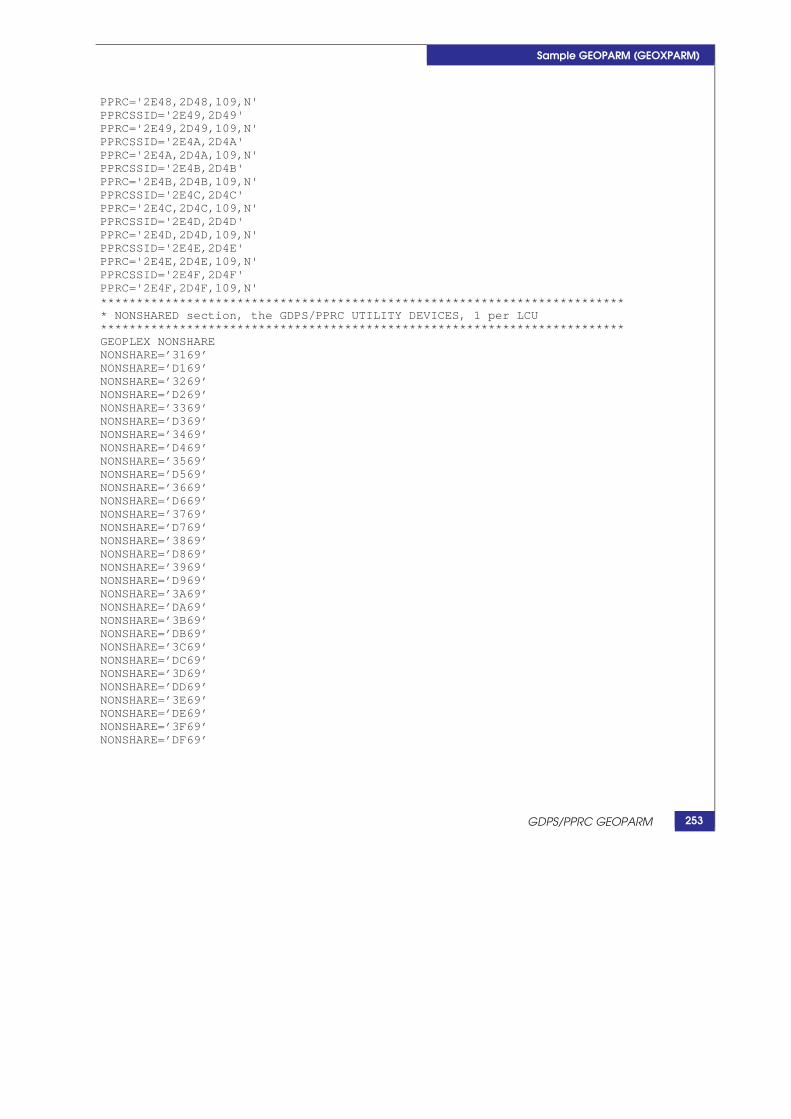
GDPS/PPRC GEOPARM
Sample GEOPARM (GEOXPARM)
PPRC='2E48,2D48,109,N' PPRCSSID='2E49,2D49' PPRC='2E49,2D49,109,N' PPRCSSID='2E4A,2D4A' PPRC='2E4A,2D4A,109,N' PPRCSSID='2E4B,2D4B' PPRC='2E4B,2D4B,109,N' PPRCSSID='2E4C,2D4C' PPRC='2E4C,2D4C,109,N' PPRCSSID='2E4D,2D4D' PPRC='2E4D,2D4D,109,N' PPRCSSID='2E4E,2D4E' PPRC='2E4E,2D4E,109,N' PPRCSSID='2E4F,2D4F' PPRC='2E4F,2D4F,109,N' ************************************************************************* * NONSHARED section, the GDPS/PPRC UTILITY DEVICES, 1 per LCU************************************************************************* GEOPLEX NONSHARE NONSHARE=’3169’ NONSHARE=’D169’ NONSHARE=’3269’ NONSHARE=’D269’ NONSHARE=’3369’ NONSHARE=’D369’ NONSHARE=’3469’ NONSHARE=’D469’ NONSHARE=’3569’ NONSHARE=’D569’ NONSHARE=’3669’ NONSHARE=’D669’ NONSHARE=’3769’ NONSHARE=’D769’ NONSHARE=’3869’ NONSHARE=’D869’ NONSHARE=’3969’ NONSHARE=’D969’ NONSHARE=’3A69’ NONSHARE=’DA69’ NONSHARE=’3B69’ NONSHARE=’DB69’ NONSHARE=’3C69’ NONSHARE=’DC69’ NONSHARE=’3D69’ NONSHARE=’DD69’ NONSHARE=’3E69’ NONSHARE=’DE69’ NONSHARE=’3F69’ NONSHARE=’DF69’
253

Sample GEOPARM (GEOXPARM)
254 EMC Compatibility Features for IBM Copy Services on z/OS TechBook

D
GDPS/PPRC Support Matrix
This appendix contains the following information:
Support matrix .................................................................................. 256
GDPS/PPRC Support Matrix 255

g support matrix details GDPS/PPRC support to be C Compatible Peer and Compatible Native Flash for V3.9 as documented by IBM.
x (page 1 of 3)
Services on z/OS TechBook
GDPS requirement Support in Compatible MCfeature
Bas
e G
DPS/
PPRC
FR
EE
All disk subsystems that will be managed by GDPS/PPRC must support the PPRCCGROUP(Y) definition and CGROUPFREEZE. This function is also known as the GDPS FREEZE/RUN architecture.
Supported by Compatible Peer.
GD
PS/P
PRC
Fla
shC
opy
FlashCopy across different LSSs in the same disk subsystem. Supported by Compatible Native Flas.h
GDPS support for FlashCopy NOCOPY-to-COPY conversion requires that the disk subsystems housing the FlashCopy source/target devices support FlashCopy NOCOPY-to-COPY conversion.
Supported by Compatible Native Flash.
GDPS Persistent/Incremental FlashCopy support requires that the disk subsystems housing the FlashCopy source/target devices support Persistent/Incremental FlashCopy.
Supported by Compatible Native Flash.
GDPS allows data set-level FlashCopy target devices to be PPRC primary devices. This capability requires that any disk subsystem housing the FlashCopy source/target devices supports data set-level FlashCopy as well as FlashCopy onto a PPRC primary.
On Compatible Native Flash roadmap.
Preserve Mirror Function requires that disk subsystems housing the subject FlashCopy source and target devices support Remote Pair FlashCopy.
Compatible Native Flash supports Remote Pair FlashCopy
GDPS support of Space Efficient FlashCopy requires that the disk subsystems housing the FlashCopy source/target devices support the FlashCopy Space Efficient capability.
Compatible Native Flash does not support FlashCopy SEfunctionality. An equivalent capability is provided by defining the FlashCopy target devices in a thin pool and use FlashCopy NOCOPY.
perS
wap
GDPS/PPRC HyperSwap requires that all disk subsystems managed by GDPS are HyperSwap-capable. HyperSwap-capable disk subsystems are subsystems that support the Extended CQUERYfunction.
Supported by Compatible Peer.
GDPS/PPRC Support Matrix
Support matrix The followin found in EM GDPS/PPRC
Table 17 Support Matri
256 EMC Compatibility Features for IBM Copy
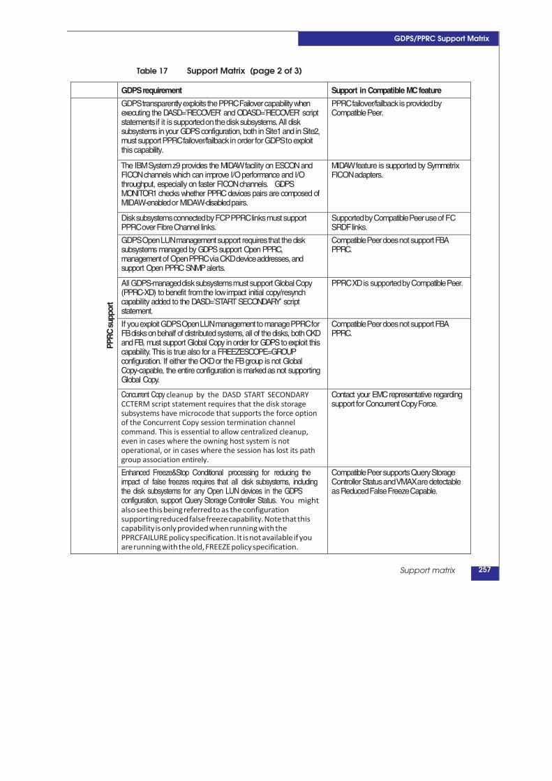
GDPS/PPRC Support Matrix
Table 17 Support Matrix (page 2 of 3)
GDPS requirement Support in Compatible MCfeature
PPR
C s
uppo
rt GDPS transparently exploits the PPRC Failover capability when executing the DASD=’RECOVER’ and ODASD=’RECOVER’ script statements if it is supported on the disk subsystems. All disk subsystems inyour GDPS configuration, both in Site1 and in Site2, must support PPRC failover/failback in order for GDPS to exploit this capability.
PPRC failover/failback is provided by Compatible Peer.
The IBMSystemz9 provides the MIDAWfacility on ESCON and FICONchannels which can improve I/O performance and I/O throughput, especially on faster FICONchannels. GDPS MONITOR1 checks whether PPRC devices pairs are composed of MIDAW-enabled or MIDAW-disabled pairs.
MIDAWfeature is supported by Symmetrix FICON adapters.
Disk subsystems connected by FCP PPRC links must support PPRC over Fibre Channel links.
Supported by Compatible Peer use of FC SRDF links.
GDPS Open LUN management support requires that the disk subsystems managed by GDPS support Open PPRC, management of Open PPRC via CKD device addresses, and support Open PPRC SNMPalerts.
Compatible Peer does not support FBA PPRC.
All GDPS-managed disk subsystems must support Global Copy (PPRC-XD) to benefit fromthe lowimpact initial copy/resynch capability added to the DASD=’START SECONDARY’ script statement.
PPRC XDis supported by Compatible Peer.
If you exploit GDPS Open LUN management to manage PPRC for FBdisks on behalf of distributed systems, all of the disks, both CKD and FB, must support Global Copy inorder for GDPS toexploit this capability. This is true also for a FREEZESCOPE=GROUP configuration. If either the CKDor the FBgroup is not Global Copy-capable, the entire configuration is markedas not supporting Global Copy.
Compatible Peer does not support FBA PPRC.
Concurrent Copy cleanup by the DASD START SECONDARY CCTERM script statement requires that the disk storage subsystems have microcode that supports the force option of the Concurrent Copy session termination channel command. This is essential to allow centralized cleanup, even in cases where the owning host system is not operational, or in cases where the session has lost its path group association entirely.
Contact your EMCrepresentative regarding support for Concurrent Copy Force.
Enhanced Freeze&Stop Conditional processing for reducing the impact of false freezes requires that all disk subsystems, including the disk subsystems for any Open LUN devices in the GDPS configuration, support Query Storage Controller Status. You might also see this being referred to as the configuration supporting reduced false freeze capability. Note that this capability is only provided when running with the PPRCFAILURE policy specification. It is not available if you are running with the old, FREEZE policy specification.
Compatible Peer supports Query Storage Controller Status and VMAX are detectable as Reduced False Freeze Capable.
Support matrix 257

x (page 3 of 3)
GDPS requirement Support in Compatible MCfeature
DS8K
Syne
rgy
Pack
age
2
GDPS proactive unplanned HyperSwap, in response to acute health events in the disk subsystemrequires that the disk subsystems in the GDPS configuration support the Storage Controller Health Message function. In a mixed configuration, only those disk subsystems with this capability raise the necessary attention message to trigger a proactive HyperSwap. For failures of other disk subsystems that do not support this feature, HyperSwap should trigger only after a host I/O from a GDPS system is impacted. Also note that the proactive unplanned HyperSwap trigger is only enabled when running with the PRIMARYFAILURE policy specification. It is not available when you are running with the old FREEZE policy specification.
We believe VMAX arrays and Compatible Peer support of the Storage Controller Health Message is unwarranted at this time. The two ENF 64 return codes that GDPS employs for HyperSwap triggers have no analogous meaning in VMAX architecture.
Freeze triggering based on LSS summary notification of PPRC suspend events requires that the disk subsystems in the GDPS configuration support the Summary Event Notification for PPRC Suspends (PPRCSUM) function. Configurations with a mixture of disk subsystems that do and do not support PPRCSUM are supported.
Summary Event notification is not supported by Compatible Peer.
Services on z/OS TechBook
GDPS/PPRC Support Matrix
Table 17 Support Matri
258 EMC Compatibility Features for IBM Copy