EMBRAGUE FRENO RESORTES
40
Wrap Spring Clutches and Clutch/Brakes
-
Upload
johan-gallo -
Category
Documents
-
view
224 -
download
0
Transcript of EMBRAGUE FRENO RESORTES
7/21/2019 EMBRAGUE FRENO RESORTES
http://slidepdf.com/reader/full/embrague-freno-resortes 1/40
Wrap Spring
Clutches and
Clutch/Brakes
7/21/2019 EMBRAGUE FRENO RESORTES
http://slidepdf.com/reader/full/embrague-freno-resortes 2/40
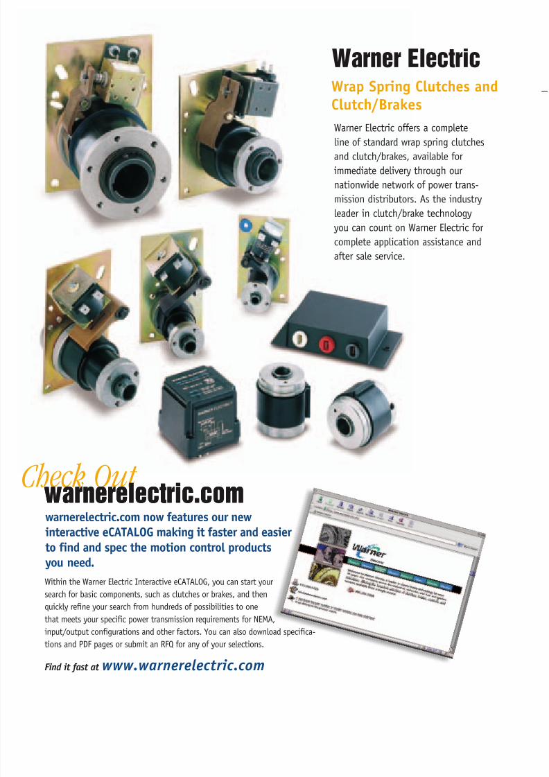
Check Out warnerelectric.comwarnerelectric.comwarnerelectric.com now features our new
interactive eCATALOG making it faster and easier
to find and spec the motion control productsyou need.
Within the Warner Electric Interactive eCATALOG, you can start your
search for basic components, such as clutches or brakes, and then
quickly refine your search from hundreds of possibilities to one
that meets your specific power transmission requirements for NEMA,
input/output configurations and other factors. You can also download specifica-
tions and PDF pages or submit an RFQ for any of your selections.
Find it fast at www.warnerelectric.com
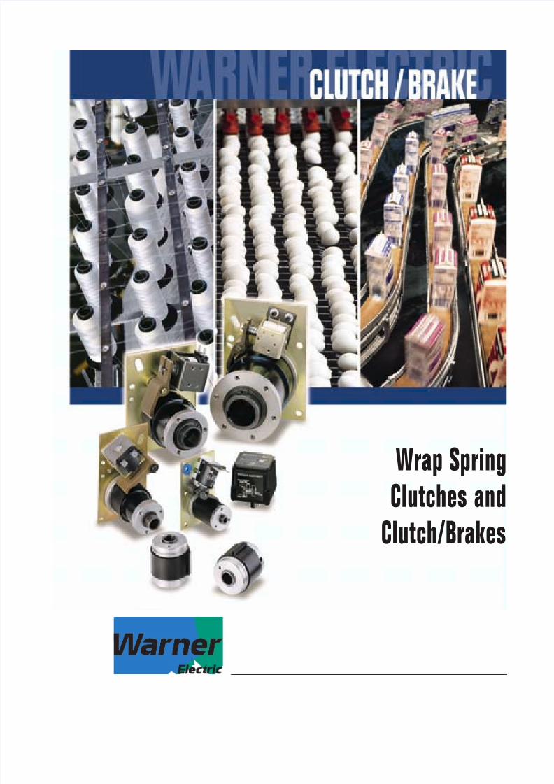
Warner Electric
Warner Electric offers a complete
line of standard wrap spring clutches
and clutch/brakes, available for
immediate delivery through our
nationwide network of power trans-
mission distributors. As the industry
leader in clutch/brake technology
you can count on Warner Electric for
complete application assistance and
after sale service.
Wrap Spring Clutches and
Clutch/Brakes
7/21/2019 EMBRAGUE FRENO RESORTES
http://slidepdf.com/reader/full/embrague-freno-resortes 3/40Warner Electric 800-825-6544 1
Introduction
Wrap Spring Product Line . . . . . . . . . . . . . . . . . . .2
Principle of Operation . . . . . . . . . . . . . . . . . . . . .3
Application Examples . . . . . . . . . . . . . . . . . . . . . .4
Selection . . . . . . . . . . . . . . . . . . . . . . . . . . . . . . . . . .6
CB Mounting Requirements . . . . . . . . . . . . . . .8
CB Stop Collar Adjustment . . . . . . . . . . . . . . .10
CB Spring Differential Setting . . . . . . . . . . . .11
CB Series Clutch/Brakes
Features . . . . . . . . . . . . . . . . . . . . . . . . . . . . . . . .12
Specifications/How-to-Order . . . . . . . . . . . . . . .13Dimensions . . . . . . . . . . . . . . . . . . . . . . . . . . .14-18
SCB Series Clutch/Brakes
Features . . . . . . . . . . . . . . . . . . . . . . . . . . . . . . . .19
Specifications/How-to-Order . . . . . . . . . . . . . . .20
Dimensions . . . . . . . . . . . . . . . . . . . . . . . . . . .21-23
WSC Series Clutches
Features . . . . . . . . . . . . . . . . . . . . . . . . . . . . . . . .24
Specifications/How-to-Order . . . . . . . . . . . . . . .25
Dimensions . . . . . . . . . . . . . . . . . . . . . . . . . . .26-29
Power Supplies . . . . . . . . . . . . . . . . . . . . . . . .30-31
Application Engineering . . . . . . . . . . . . . . . . .32-34
Part Numbers . . . . . . . . . . . . . . . . . . . . . . . . . . . . .35
Application Data Form . . . . . . . . . . . . . . . . . . . . .36
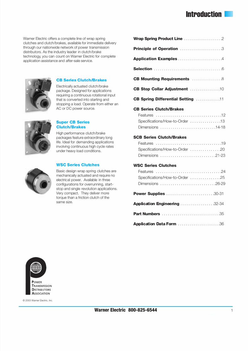
Warner Electric offers a complete line of wrap spring
clutches and clutch/brakes, available for immediate delivery
through our nationwide network of power transmission
distributors. As the industry leader in clutch/brake
technology, you can count on Warner Electric for complete
application assistance and after-sale service.
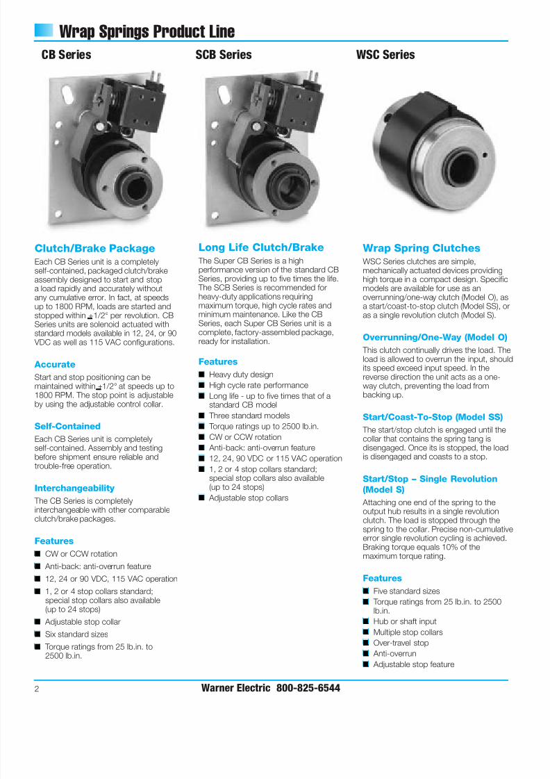
CB Series Clutch/Brakes
Electrically actuated clutch/brake
package. Designed for applications
requiring a continuous rotational input
that is converted into starting and
stopping a load. Operate from either an
AC or DC power source.
Super CB SeriesClutch/Brakes
High performance clutch/brake
packages feature extraordinary long
life. Ideal for demanding applications
involving continuous high cycle rates
under heavy load conditions.
WSC Series Clutches
Basic design wrap spring clutches are
mechanically actuated and require no
electrical power. Available in three
configurations for overrunning, start-stop and single revolution applications.
Very compact. They deliver more
torque than a friction clutch of the
same size.
© 2003 Warner Electric, Inc.
7/21/2019 EMBRAGUE FRENO RESORTES
http://slidepdf.com/reader/full/embrague-freno-resortes 4/40
7/21/2019 EMBRAGUE FRENO RESORTES
http://slidepdf.com/reader/full/embrague-freno-resortes 5/40
Basic Design Principal
Warner Electric 800-825-6544 3
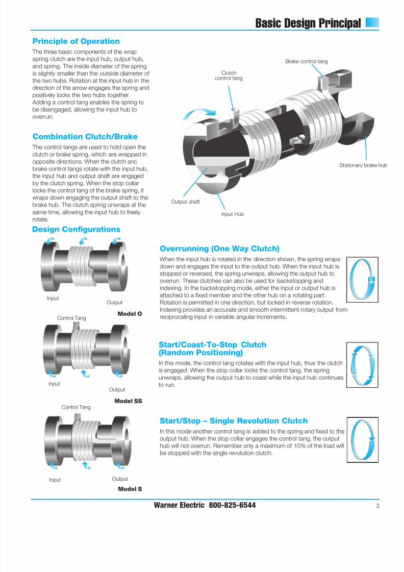
Brake control tang
Stationary brake
Clutchcontrol tang
Input Hub
Output shaft
Input Output
Control Tang
Design Configurations
Overrunning (One Way Clutch)
When the input hub is rotated in the direction shown, the spring wraps
down and engages the input to the output hub. When the input hub is
stopped or reversed, the spring unwraps, allowing the output hub to
overrun. These clutches can also be used for backstopping and
indexing. In the backstopping mode, either the input or output hub is
attached to a fixed member and the other hub on a rotating part.
Rotation is permitted in one direction, but locked in reverse rotation.Indexing provides an accurate and smooth intermittent rotary output from
reciprocating input in variable angular increments.
Start/Coast-To-Stop Clutch(Random Positioning)
In this mode, the control tang rotates with the input hub, thus the clutch
is engaged. When the stop collar locks the control tang, the spring
unwraps, allowing the output hub to coast while the input hub continues
to run.
Start/Stop – Single Revolution Clutch
In this mode another control tang is added to the spring and fixed to the
output hub. When the stop collar engages the control tang, the output
hub will not overrun. Remember only a maximum of 10% of the load will
be stopped with the single revolution clutch.
Input Output
InputOutput
Control Tang
Model SS
Model S
Model O
Principle of Operation
The three basic components of the wrap
spring clutch are the input hub, output hub,
and spring. The inside diameter of the spring
is slightly smaller than the outside diameter of
the two hubs. Rotation at the input hub in the
direction of the arrow engages the spring and
positively locks the two hubs together.
Adding a control tang enables the spring tobe disengaged, allowing the input hub to
overrun.
Combination Clutch/Brake
The control tangs are used to hold open the
clutch or brake spring, which are wrapped in
opposite directions. When the clutch and
brake control tangs rotate with the input hub,
the input hub and output shaft are engaged
by the clutch spring. When the stop collar
locks the control tang of the brake spring, it
wraps down engaging the output shaft to thebrake hub. The clutch spring unwraps at the
same time, allowing the input hub to freely
rotate.
7/21/2019 EMBRAGUE FRENO RESORTES
http://slidepdf.com/reader/full/embrague-freno-resortes 6/40
Application Examples
4 Warner Electric 800-825-6544
The features of wrap spring clutches and brakes;
accuracy, repeatability, high torque-to-size ratio, low
power consumption and long life make them an ideal
solution for a wide range of motion control applications.
Basic functions include overrunning, single revolution,
random positioning start-stop, high cycle rate rapid
start-stops and accurate, repeatable positioning.
Typical Applications
■ Conveyors
■ Rotary indexing tables
■ Packaging equipment
■ Bagging machinery
■ Collators
■ Cut-off machines
■ Vending machines
■ Copiers
■ Food processing equipment
■ Paper feeds
■ Folders
■ Material handling equipment
■ Riveters, staplers and stitching machines
■ Sorters
■ Punch presses
■ Textile machines
■ Film and wire processing
Application Examples
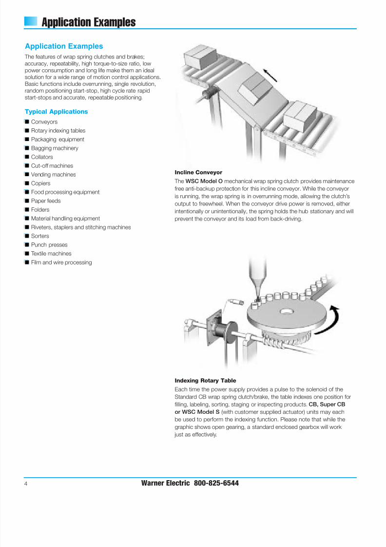
Incline Conveyor
The WSC Model O mechanical wrap spring clutch provides maintenance
free anti-backup protection for this incline conveyor. While the conveyoris running, the wrap spring is in overrunning mode, allowing the clutch’s
output to freewheel. When the conveyor drive power is removed, either
intentionally or unintentionally, the spring holds the hub stationary and will
prevent the conveyor and its load from back-driving.
Indexing Rotary TableEach time the power supply provides a pulse to the solenoid of the
Standard CB wrap spring clutch/brake, the table indexes one position for
filling, labeling, sorting, staging or inspecting products. CB, Super CB
or WSC Model S (with customer supplied actuator) units may each
be used to perform the indexing function. Please note that while the
graphic shows open gearing, a standard enclosed gearbox will work
just as effectively.
7/21/2019 EMBRAGUE FRENO RESORTES
http://slidepdf.com/reader/full/embrague-freno-resortes 7/40Warner Electric 800-825-6544 5
Application Examples
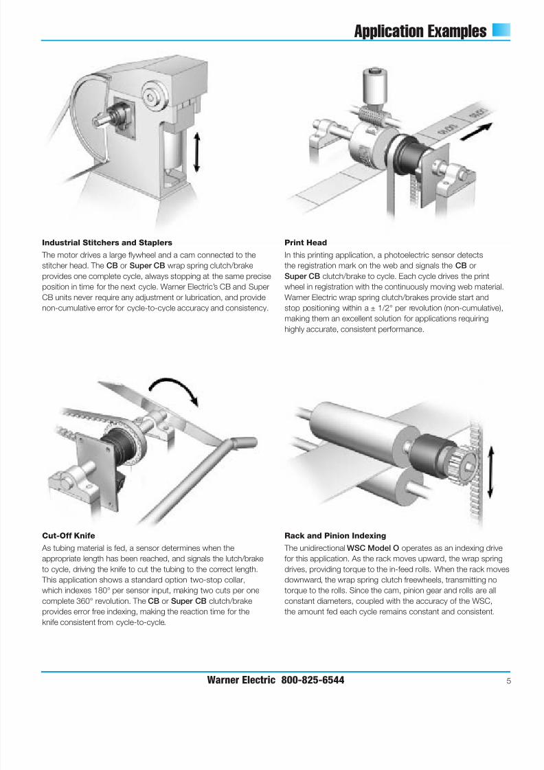
Industrial Stitchers and Staplers
The motor drives a large flywheel and a cam connected to the
stitcher head. TheCB
orSuper CB
wrap spring clutch/brakeprovides one complete cycle, always stopping at the same precise
position in time for the next cycle. Warner Electric’s CB and Super
CB units never require any adjustment or lubrication, and provide
non-cumulative error for cycle-to-cycle accuracy and consistency.
Rack and Pinion Indexing The unidirectional WSC Model O operates as an indexing drive
for this application. As the rack moves upward, the wrap spring
drives, providing torque to the in-feed rolls. When the rack moves
downward, the wrap spring clutch freewheels, transmitting no
torque to the rolls. Since the cam, pinion gear and rolls are all
constant diameters, coupled with the accuracy of the WSC,
the amount fed each cycle remains constant and consistent.
Print Head
In this printing application, a photoelectric sensor detects
the registration mark on the web and signals theCB
orSuper CB clutch/brake to cycle. Each cycle drives the print
wheel in registration with the continuously moving web material.
Warner Electric wrap spring clutch/brakes provide start and
stop positioning within a ± 1/2° per revolution (non-cumulative),
making them an excellent solution for applications requiring
highly accurate, consistent performance.
Cut-Off Knife As tubing material is fed, a sensor determines when the
appropriate length has been reached, and signals the lutch/brake
to cycle, driving the knife to cut the tubing to the correct length.
This application shows a standard option two-stop collar,
which indexes 180° per sensor input, making two cuts per one
complete 360° revolution. The CB or Super CB clutch/brake
provides error free indexing, making the reaction time for the
knife consistent from cycle-to-cycle.
7/21/2019 EMBRAGUE FRENO RESORTES
http://slidepdf.com/reader/full/embrague-freno-resortes 8/40
Selection
6 Warner Electric 800-825-6544
Max. Torque
Function Performance Wrap Spring Starting Stopping Max. Actuation
Product lb. in. lb. in. RPM Method
(N-m) (N-m)
marginally within the capabilities of aspecific product, consider using the nextlarger size. In instances where requiredload/speed performance data is knownand unit size is uncertain, use thetechnical selection process starting onpage 28 which will help you review the
necessary aspects of your application.
Step 1Determine clutch or brake
function
Wrap spring clutches and brakes can
perform three control functions—
overrunning, start/coast-to-stop, and
single revolution. Determine the function
which will provide the best control for
your application. Using the chart below,
select the series which best fits your
application requirements.
Step 2Determine size
To select the correct size unit, determine
the maximum RPM at which the clutch
or brake will be operated and the shaft
diameter on which the wrap spring unit
will be mounted. A wrap spring clutchengages almost instantly, and, since
spring wrap increases with load, the unit
must be sized carefully to insure that it is
correct for the application. If there is any
uncertainty regarding the correct unit
size, we recommend using the technical
selection process starting on page 32. To
select the correct wrap spring unit, locate
the corresponding speed and shaft
diameter points on the appropriate chart
on page 7. For applications requiring
speed or diameter values higher than
those illustrated, please contact your
local Warner Electric Distributor, yourMarket Representative, or Warner Electric
Technical Support at (800) 825-9050.
Selection by Function
For Product SelectionFollow 3 Easy Steps
Wrap spring clutches and brakes are
pre-packaged, pre-assembled units
which are as easy to select as they are
to install. The simple three step selection
process includes:
Step 1 Determine the clutch or
brake function
Step 2 Determine size
Step 3 Verify design considerations
This selection process is based on theassumption that the diameter of the shaftat the clutch or clutch/brake location hasbeen designed through good machinedesign practice. For most applications,this process will determine the correct
size product. When the performancerequirements of a given application are
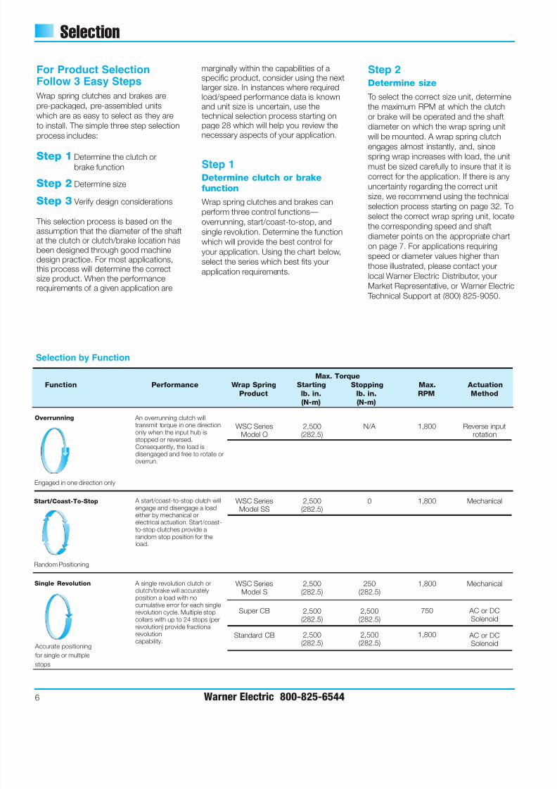
Overrunning
Start/Coast-To-Stop
Single Revolution
Accurate positioning
for single or multiple
stops
Random Positioning
An overrunning clutch willtransmit torque in one directiononly when the input hub isstopped or reversed.Consequently, the load isdisengaged and free to rotate oroverrun.
WSC SeriesModel O
2,500(282.5)
N/A 1,800 Reverse inputrotation
A start/coast-to-stop clutch willengage and disengage a loadeither by mechanical orelectrical actuation. Start/coast-to-stop clutches provide arandom stop position for theload.
WSC SeriesModel SS
2,500(282.5)
0 1,800 Mechanical
A single revolution clutch orclutch/brake will accuratelyposition a load with nocumulative error for each singlerevolution cycle. Multiple stopcollars with up to 24 stops (perrevolution) provide fractionalrevolutioncapability.
WSC SeriesModel S
Super CB
Standard CB
2,500(282.5)
2,500(282.5)
2,500(282.5)
250(282.5)
2,500(282.5)
2,500(282.5)
1,800
750
1,800
Mechanical
AC or DCSolenoid
AC or DCSolenoid
Engaged in one direction only
7/21/2019 EMBRAGUE FRENO RESORTES
http://slidepdf.com/reader/full/embrague-freno-resortes 9/40
Selection
Warner Electric 800-825-6544 7
Step 3 Verify design function
considerations
Once the appropriate series and modelsize have been determined, review thedesign considerations. A complete
checklist of these and other optionsavailable are detailed in the How toOrder section for each series.
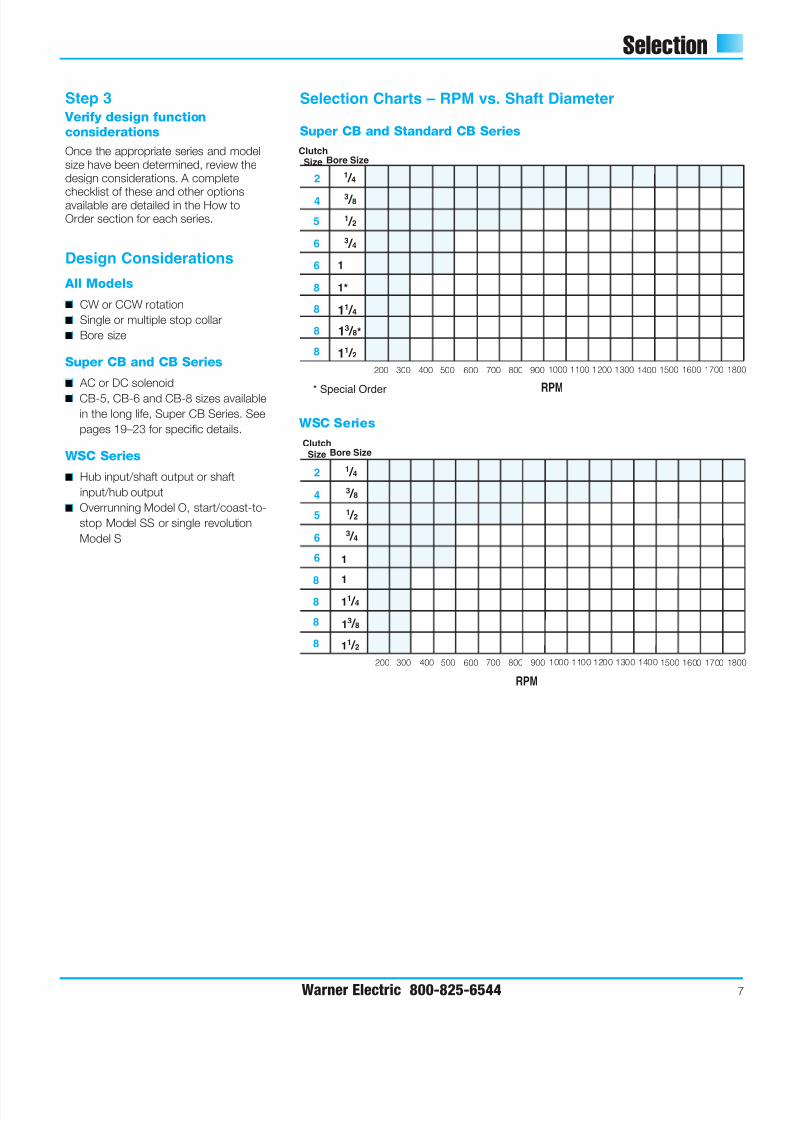
2
6
6
4
5
1 / 4
3 / 8
1 / 2
3 / 4
1
ClutchSize Bore Size
RPM
200 300 400 500 600 700 800 900 1000 1100 1200 1300 1500 1700 1801400 1600
8
8
8
8
1*
11 / 4
13 / 8*
11 / 2
* Special Order
2
6
6
8
8
8
8
4
5
1 / 4
3 / 8
1 / 2
3 / 4
1
1
11 / 4
13 / 8
11 / 2
Clutch
Size Bore Size
RPM
200 300 400 500 600 700 800 900 1000 1100 1200 1300 1400 1500 1600 1700 180
Selection Charts – RPM vs. Shaft Diameter
Super CB and Standard CB Series
WSC Series
Design Considerations
All Models
■ CW or CCW rotation
■ Single or multiple stop collar
■ Bore size
Super CB and CB Series
■ AC or DC solenoid
■ CB-5, CB-6 and CB-8 sizes available
in the long life, Super CB Series. See
pages 19–23 for specific details.
WSC Series
■ Hub input/shaft output or shaft
input/hub output
■ Overrunning Model O, start/coast-to-
stop Model SS or single revolution
Model S
7/21/2019 EMBRAGUE FRENO RESORTES
http://slidepdf.com/reader/full/embrague-freno-resortes 10/40
CB Mounting Requirements
8 Warner Electric 800-825-6544
CB Mounting RequirementsMaximum Radial Bearing Load atMaximum Speed
CB-2 = 7.5 lbs.
CB-4 = 14 lbs.
CB-5/Super CB-5 = 32 lbs.
CB-6/Super CB-6 = 63 lbs.
CB-8/Super CB-8 = 300 lbs.
CB and Super CB style clutch/brakes are
designed for horizontal shaft mounting.
While it is possible to mount units
vertically, vertically mounted units will see
lower life than those mounted horizontally
due to the wear between hubs resulting
from gravity.
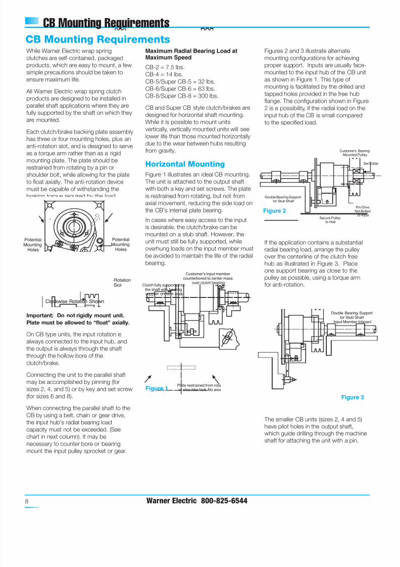
Horizontal Mounting
Figure 1 illustrates an ideal CB mounting.
The unit is attached to the output shaft
with both a key and set screws. The plate
is restrained from rotating, but not fromaxial movement, reducing the side load on
the CB’s internal plate bearing.
In cases where easy access to the input
is desirable, the clutch/brake can be
mounted on a stub shaft. However, the
unit must still be fully supported, while
overhung loads on the input member must
be avoided to maintain the life of the radial
bearing.
Figures 2 and 3 illustrate alternate
mounting configurations for achieving
proper support. Inputs are usually face-
mounted to the input hub of the CB unit
as shown in Figure 1. This type of
mounting is facilitated by the drilled and
tapped holes provided in the free hub
flange. The configuration shown in Figure2 is a possibility, if the radial load on the
input hub of the CB is small compared
to the specified load.
If the application contains a substantial
radial bearing load, arrange the pulley
over the centerline of the clutch free
hub as illustrated in Figure 3. Place
one support bearing as close to the
pulley as possible, using a torque arm
for anti-rotation.
The smaller CB units (sizes 2, 4 and 5)
have pilot holes in the output shaft,
which guide drilling through the machine
shaft for attaching the unit with a pin.
While Warner Electric wrap spring
clutches are self-contained, packaged
products, which are easy to mount, a few
simple precautions should be taken to
ensure maximum life.
All Warner Electric wrap spring clutch
products are designed to be installed inparallel shaft applications where they are
fully supported by the shaft on which they
are mounted.
Each clutch/brake backing plate assembly
has three or four mounting holes, plus an
anti-rotation slot, and is designed to serve
as a torque arm rather than as a rigid
mounting plate. The plate should be
restrained from rotating by a pin or
shoulder bolt, while allowing for the plate
to float axially. The anti-rotation device
must be capable of withstanding the
braking torque required by the load.
Important: Do not rigidly mount unit.
Plate must be allowed to “float” axially.
On CB type units, the input rotation is
always connected to the input hub, and
the output is always through the shaft
through the hollow bore of the
clutch/brake.
Connecting the unit to the parallel shaft
may be accomplished by pinning (for
sizes 2, 4, and 5) or by key and set screw
(for sizes 6 and 8).
When connecting the parallel shaft to the
CB by using a belt, chain or gear drive,
the input hub’s radial bearing load
capacity must not be exceeded. (See
chart in next column). It may be
necessary to counter bore or bearing
mount the input pulley sprocket or gear.
Double Bearing Supportfor Stub Shaft
Input Member Inboard
+ +
+
+ +
+ +
+ + +
+
PotentialMounting
Holes
PotentialMounting
Holes
Anti-RotationSlot
Clockwise Rotation Shown
Clutch fully supported bythe shaft with bearingsupport on both ends
Customer's Input membercounterbored to center mass
over clutch bearing
Plate restrained from rotating by pinor shoulder bolt. No axial binding.
Figure 1
Figure 3
Customer's Bearing-Mounted Pulley
Double Bearing Supportfor Stub Shaft
Set Co
Pin DriveNot Bolted
to InputSecure Pulley
to Hub
Figure 2
7/21/2019 EMBRAGUE FRENO RESORTES
http://slidepdf.com/reader/full/embrague-freno-resortes 11/40Warner Electric 800-825-6544 9
CB Mounting Requirements
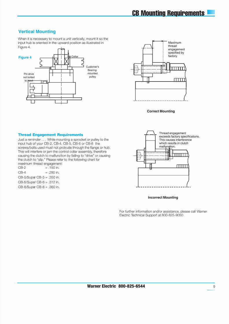
When it is necessary to mount a unit vertically, mount it so the
input hub is oriented in the upward position as illustrated in
Figure 4.
Thread Engagement Requirements
Just a reminder . . . While mounting a sprocket or pulley to the
input hub of your CB-2, CB-4, CB-5, CB-6 or CB-8 the
screws/bolts used must not protrude through the flange or hub.
This will interfere or jam the control collar assembly, therefore
causing the clutch to malfunction by failing to “drive” or causing
the clutch to “slip.” Please refer to the following chart for
maximum thread engagement:
CB-2 = .150 in.
CB-4 = .280 in.
CB-5/Super CB-5 = .350 in.
CB-6/Super CB-6 = .312 in.
CB-8/Super CB-8 = .360 in.
Vertical Mounting
Pin drive
not bolted
to input
Customer's
Bearing-
mounted
pulley
Set CollarFigure 4
Maximumthreadengagementspecified by
factory
Correct Mounting
Thread engagementexceeds factory specifications.This causes interferencewhich results in clutchmalfunction.
Incorrect Mounting
For further information and/or assistance, please call WarnerElectric Technical Support at 800-825-9050.
7/21/2019 EMBRAGUE FRENO RESORTES
http://slidepdf.com/reader/full/embrague-freno-resortes 12/4010 Warner Electric 800-825-6544
CB Stop Collar Adjustment
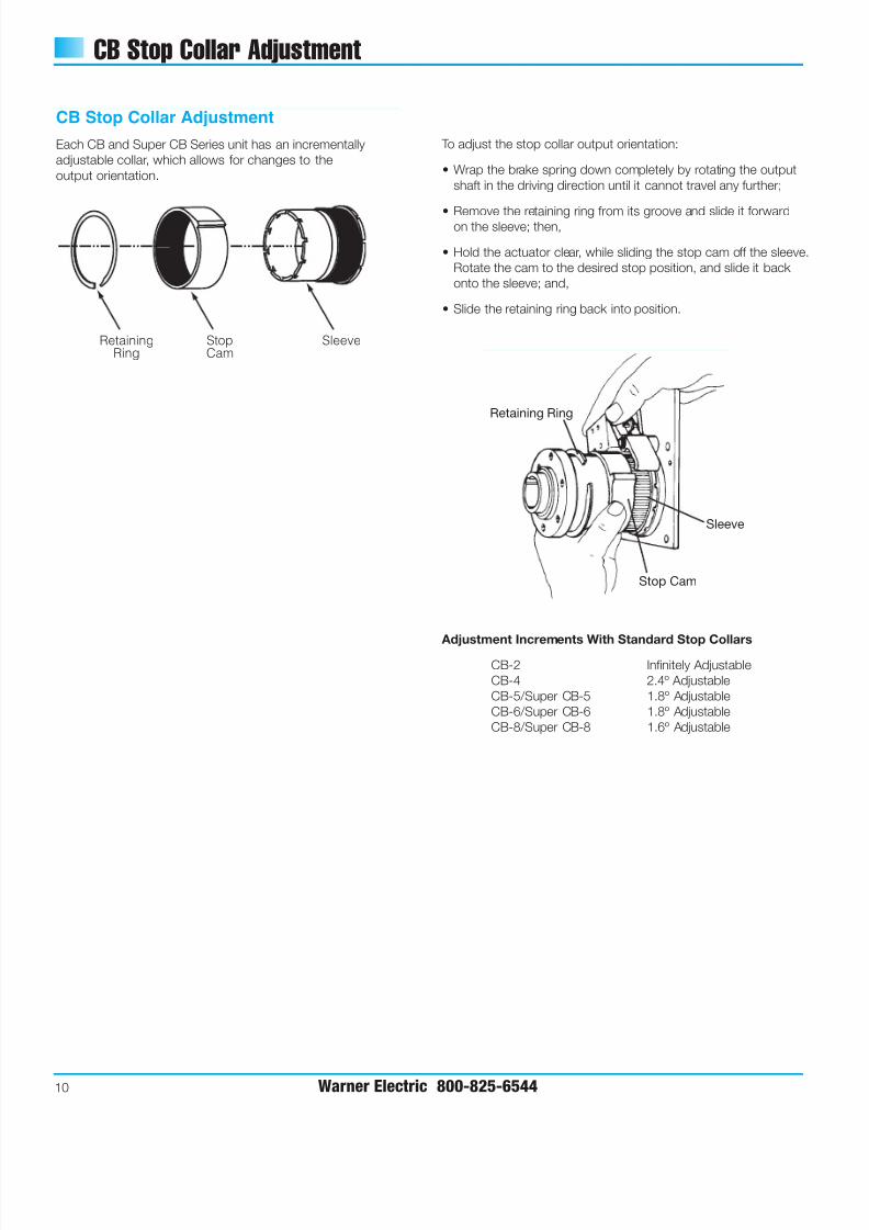
CB Stop Collar Adjustment
Each CB and Super CB Series unit has an incrementally
adjustable collar, which allows for changes to the
output orientation.
RetainingRing
StopCam
Sleeve
Adjustment Increments With Standard Stop Collars
CB-2 Infinitely Adjustable
CB-4 2.4º Adjustable
CB-5/Super CB-5 1.8º Adjustable
CB-6/Super CB-6 1.8º Adjustable
CB-8/Super CB-8 1.6º Adjustable
Retaining Ring
Sleeve
Stop Cam
To adjust the stop collar output orientation:
• Wrap the brake spring down completely by rotating the output
shaft in the driving direction until it cannot travel any further;
• Remove the retaining ring from its groove and slide it forwardon the sleeve; then,
• Hold the actuator clear, while sliding the stop cam off the sleeve.
Rotate the cam to the desired stop position, and slide it back
onto the sleeve; and,
• Slide the retaining ring back into position.
7/21/2019 EMBRAGUE FRENO RESORTES
http://slidepdf.com/reader/full/embrague-freno-resortes 13/40Warner Electric 800-825-6544 11
CB Spring Differential Setting
8. If the overtravel measurement is within these specified limits,
reinstall the retaining ring and the unit’s overtravel is reset.
9 A. If the overtravel exceeds the specified limit, move the brake
spring backwards one slot (against the direction of rotation)and repeat steps two through seven.
B. If the overtravel is less than the specified limit, move the
brake spring forward one slot (in the direction of rotation,)
and repeat steps two through seven.
If Spring Replacement Is Not Required
If the unit is disassembled and the drive and/or brake springs
do not need to be replaced, proceed as follows:
• Reposition the drive and brake springs into their original
positions onto the output shaft assembly.
• Reassemble the clutch, and position the spring tangs of the
drive and brake springs in the factory marked locations on the
control collar assembly (on the control collar, the designated
tang slots are indicated with punch marks on either side of
each slot).
• After the unit is completely reassembled, the differential setting
should match that of the original factory setting.
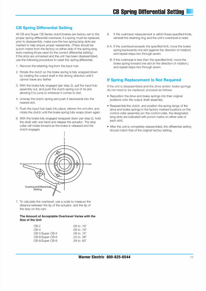
CB Spring Differential Setting
All CB and Super CB Series clutch/brakes are factory-set to the
proper spring differential overtravel. If a spring must be replaced,
prior to disassembly, make sure the two spring tang slots are
marked to help ensure proper reassembly. (There should be
punch marks from the factory on either side of the spring tang
slots marking those used for the correct differential setting.)
If the slots are unmarked and the unit has been disassembled,
use the following procedure to reset the spring differential.
1. Remove the retaining ring from the input hub.
2. Rotate the clutch so the brake spring is fully wrapped down
by rotating the output shaft in the driving direction until it
cannot travel any farther.
3. With the brake fully engaged (per step 2), pull the input hub
assembly out, and push the clutch spring out of its slot,
allowing it to jump to wherever it comes to rest.
4. Unwrap the clutch spring and push it backwards into the
nearest slot.
5. Push the input hub back into place, release the actuator, and
rotate the clutch until the brake spring fully wraps down again.
6. With the brake fully engaged (wrapped down per step 2), hold
the shaft with one hand and release the actuator. The stop
collar will rotate forward as the brake is released and the
clutch engages.
7. To calculate the overtravel, use a scale to measure the
distance between the tip of the actuator, and the tip of
the stop on the cam
The Amount of Acceptable Overtravel Varies with the
Size of the Unit
CB-2 .09 to .19"
CB-4 .09 to .19"
CB-5/Super CB-5 .09 to .19"
CB-6/Super CB-6 .22 to .38"
CB-8/Super CB-8 .39 to .60"
+
+
+
Overtravel/DifferentialSetting
7/21/2019 EMBRAGUE FRENO RESORTES
http://slidepdf.com/reader/full/embrague-freno-resortes 14/40
CB Series Clutch/Brakes
12 Warner Electric 800-825-6544
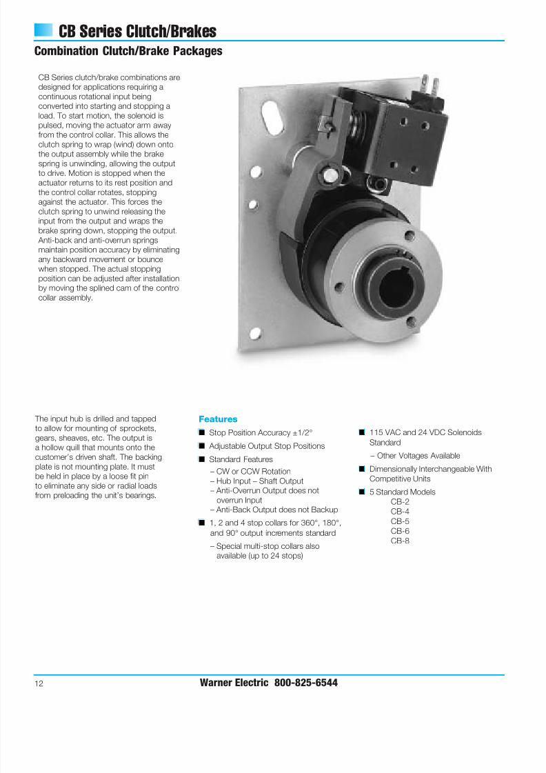
Combination Clutch/Brake Packages
CB Series clutch/brake combinations are
designed for applications requiring a
continuous rotational input being
converted into starting and stopping a
load. To start motion, the solenoid is
pulsed, moving the actuator arm away
from the control collar. This allows theclutch spring to wrap (wind) down onto
the output assembly while the brake
spring is unwinding, allowing the output
to drive. Motion is stopped when the
actuator returns to its rest position and
the control collar rotates, stopping
against the actuator. This forces the
clutch spring to unwind releasing the
input from the output and wraps the
brake spring down, stopping the output.
Anti-back and anti-overrun springs
maintain position accuracy by eliminating
any backward movement or bounce
when stopped. The actual stoppingposition can be adjusted after installation
by moving the splined cam of the control
collar assembly.
The input hub is drilled and tapped
to allow for mounting of sprockets,
gears, sheaves, etc. The output is
a hollow quill that mounts onto the
customer’s driven shaft. The backing
plate is not mounting plate. It must
be held in place by a loose fit pin
to eliminate any side or radial loads
from preloading the unit’s bearings.
Features
■ Stop Position Accuracy ±1/2°
■ Adjustable Output Stop Positions
■ Standard Features
– CW or CCW Rotation
– Hub Input – Shaft Output
– Anti-Overrun Output does not
overrun Input
– Anti-Back Output does not Backup
■ 1, 2 and 4 stop collars for 360°, 180°,
and 90° output increments standard
– Special multi-stop collars also
available (up to 24 stops)
■ 115 VAC and 24 VDC Solenoids
Standard
– Other Voltages Available
■ Dimensionally Interchangeable With
Competitive Units
■ 5 Standard Models
CB-2
CB-4
CB-5
CB-6
CB-8
7/21/2019 EMBRAGUE FRENO RESORTES
http://slidepdf.com/reader/full/embrague-freno-resortes 15/40
CB Series Clutch/Brake
Warner Electric 800-825-6544 13
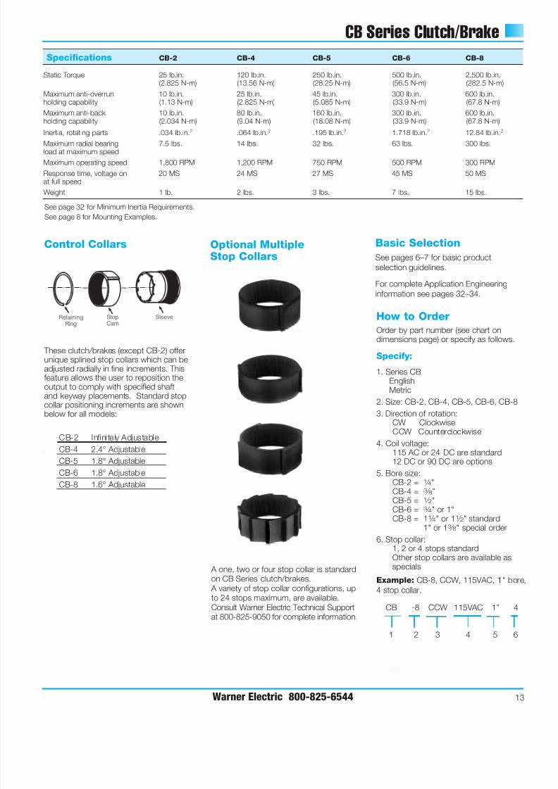
These clutch/brakes (except CB-2) offerunique splined stop collars which can beadjusted radially in fine increments. Thisfeature allows the user to reposition theoutput to comply with specified shaftand keyway placements. Standard stopcollar positioning increments are shown
below for all models:
CB-2 Infinitely Adjustable
CB-4 2.4° Adjustable
CB-5 1.8° Adjustable
CB-6 1.8° Adjustable
CB-8 1.6° Adjustable
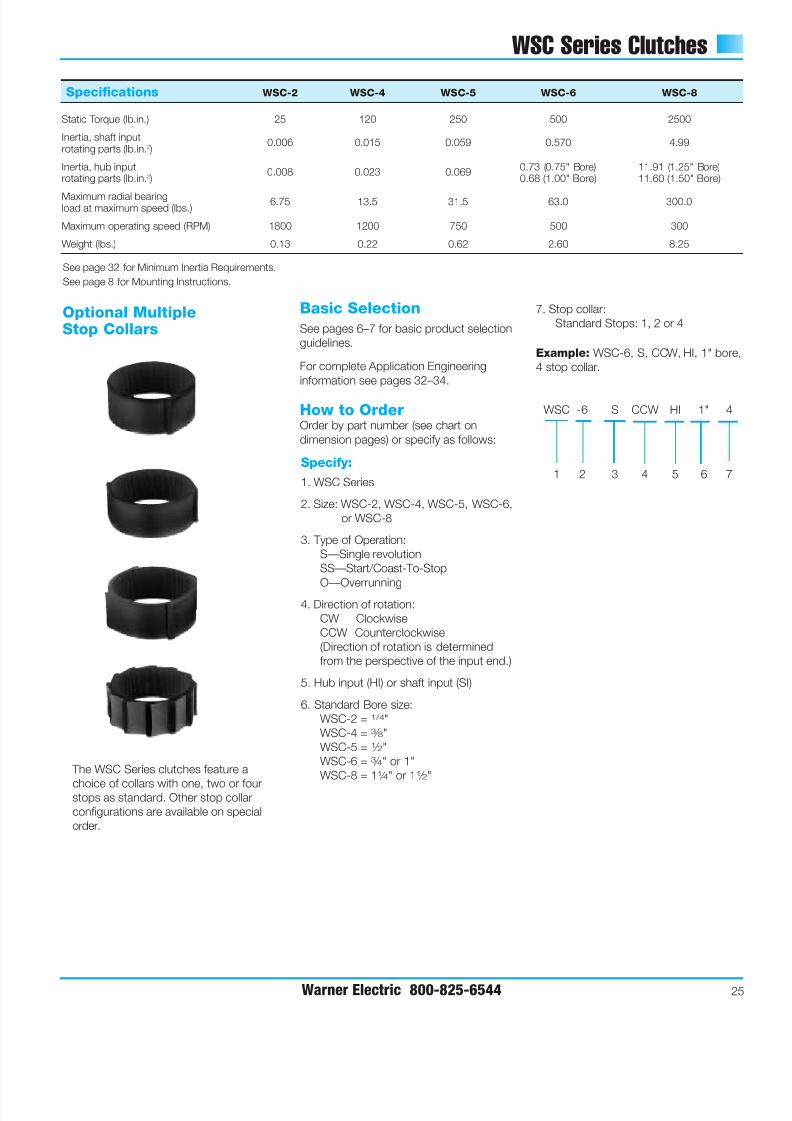
Basic Selection
See pages 6–7 for basic product
selection guidelines.
For complete Application Engineering
information see pages 32–34.
Specifications CB-2 CB-4 CB-5 CB-6 CB-8
Static Torque 25 lb.in. 120 lb.in. 250 lb.in. 500 lb.in. 2,500 lb.in.(2.825 N-m) (13.56 N-m) (28.25 N-m) (56.5 N-m) (282.5 N-m)
Maximum anti-overrun 10 lb.in. 25 lb.in. 45 lb.in. 300 lb.in. 600 lb.in.holding capability (1.13 N-m) (2.825 N-m) (5.085 N-m) (33.9 N-m) (67.8 N-m)
Maximum anti-back 10 lb.in. 80 lb.in. 160 lb.in. 300 lb.in. 600 lb.in.holding capability (2.034 N-m) (9.04 N-m) (18.08 N-m) (33.9 N-m) (67.8 N-m)
Inertia, rotating parts .034 lb.in.2 .064 lb.in.2 .195 lb.in.2 1.718 lb.in.2 12.84 lb.in.2
Maximum radial bearing 7.5 lbs. 14 lbs. 32 lbs. 63 lbs. 300 lbs.load at maximum speed
Maximum operating speed 1,800 RPM 1,200 RPM 750 RPM 500 RPM 300 RPM
Response time, voltage on 20 MS 24 MS 27 MS 45 MS 50 MSat full speed
Weight 1 lb. 2 lbs. 3 lbs. 7 lbs. 15 lbs.
See page 32 for Minimum Inertia Requirements.
See page 8 for Mounting Examples.
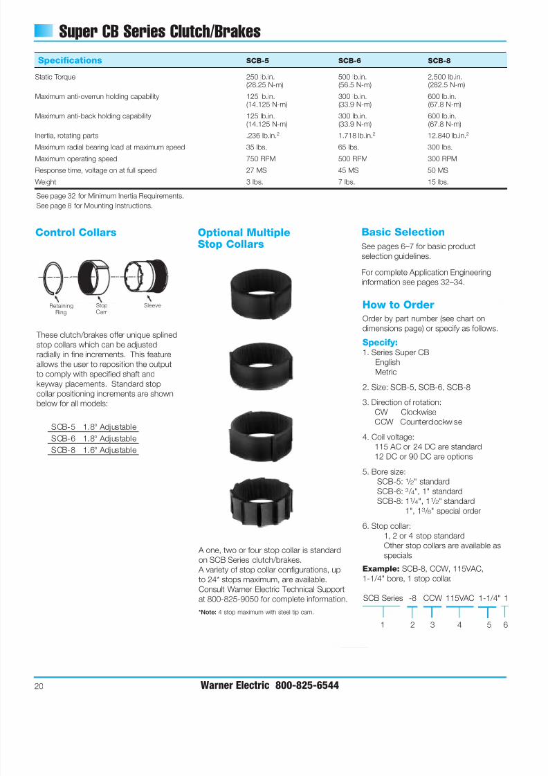
Control Collars
A one, two or four stop collar is standardon CB Series clutch/brakes.
A variety of stop collar configurations, upto 24 stops maximum, are available.Consult Warner Electric Technical Supportat 800-825-9050 for complete information.
Optional MultipleStop Collars
Order by part number (see chart ondimensions page) or specify as follows.
Specify:
1. Series CBEnglishMetric
2. Size: CB-2, CB-4, CB-5, CB-6, CB-8
3. Direction of rotation:CW ClockwiseCCW Counterclockwise
4. Coil voltage:115 AC or 24 DC are standard12 DC or 90 DC are options
5. Bore size:CB-2 = 1 ⁄ 4"CB-4 = 3 ⁄ 8"CB-5 = 1 ⁄ 2"CB-6 = 3 ⁄ 4" or 1"CB-8 = 11 ⁄ 4" or 11 ⁄ 2" standard
1" or 13 ⁄ 8" special order
6. Stop collar:1, 2 or 4 stops standardOther stop collars are available asspecials
Example: CB-8, CCW, 115VAC, 1" bore
4 stop collar.
How to OrderRetainingRing
StopCam
Sleeve
CB -8 CCW 115VAC 1" 4
1 2 3 4 5 6
7/21/2019 EMBRAGUE FRENO RESORTES
http://slidepdf.com/reader/full/embrague-freno-resortes 16/40
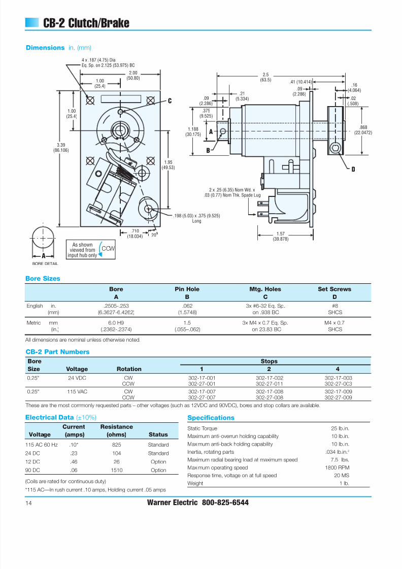
CB-2 Clutch/Brake
14 Warner Electric 800-825-6544
Dimensions in. (mm)
Bore Sizes
Bore Pin Hole Mtg. Holes Set Screws
A B C DEnglish in. .2505-.253 .062 3x #6-32 Eq. Sp. #8
(mm) (6.3627-6.4262) (1.5748) on .938 BC SHCS
Metric mm 6.0 H9 1.5 3x M4 x 0.7 Eq. Sp. M4 x 0.7
(in.) (.2362-.2374) (.055–.062) on 23.83 BC SHCS
All dimensions are nominal unless otherwise noted.
Specifications
Static Torque 25 lb.in.
Maximum anti-overrun holding capability 10 lb.in.
Maximum anti-back holding capability 10 lb.in.
Inertia, rotating parts .034 lb.in.2
Maximum radial bearing load at maximum speed 7.5 lbs.
Maximum operating speed 1800 RPM
Response time, voltage on at full speed 20 MS
Weight 1 lb.
20°
2.00(50.80)
3.39(86.106)
.710(18.034)
1.00(25.4)
1.00(25.4)
4 x .187 (4.75) DiaEq. Sp. on 2.125 (53.975) BC
.198 (5.03) x .375 (9.525)Long
1.95(49.53)
C
2 x .25 (6.35) Nom Wd. x.03 (0.77) Nom Thk. Spade Lug
B
D
A
1.57(39.878)
.375(9.525)
.09(2.286)
.21
(5.334)
1.188(30.175)
.868(22.0472)
.02(.508)
.16(4.064)
.41 (10.414)
.09(2.286)
2.5(63.5)
As shownviewed from
input hub onlyCCW
BORE DETAIL
A
Electrical Data (±10%)
Current Resistance
Voltage (amps) (ohms) Status
115 AC 60 Hz .10* 825 Standard
24 DC .23 104 Standard
12 DC .46 26 Option
90 DC .06 1510 Option
(Coils are rated for continuous duty)
*115 AC—In rush current .10 amps, Holding current .05 amps
CB-2 Part Numbers
Bore Stops
Size Voltage Rotation 1 2 4
0.25" 24 VDC CW 302-17-001 302-17-002 302-17-003CCW 302-27-001 302-27-011 302-27-003
0.25" 115 VAC CW 302-17-007 302-17-008 302-17-009
CCW 302-27-007 302-27-008 302-27-009 These are the most commonly requested parts – other voltages (such as 12VDC and 90VDC), bores and stop collars are available.
7/21/2019 EMBRAGUE FRENO RESORTES
http://slidepdf.com/reader/full/embrague-freno-resortes 17/40
7/21/2019 EMBRAGUE FRENO RESORTES
http://slidepdf.com/reader/full/embrague-freno-resortes 18/40
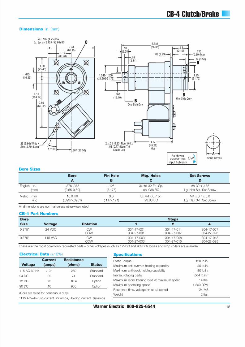
CB-5 Clutch/Brake
16 Warner Electric 800-825-6544
2.50(63.50)
4.56(115.82)
1.31
(33.27)
1.31(33.27)
2.62(66.55)
.91(23.11)
20°
4.375(111.13)
.46(11.68)
.25(6.35)
1.56(39.62)
1.09(27.69)
.09 (2.29)
.19 (4.83)
2.06(52.33)
.625(15.88)
1.5605-1.5625(39.64-39.69)
D
C
4 x .187 (4.75)DiaEq. Sp. On
3.125 (79.38) BC
.045(1.14)
Max
BONE SIDE ONLYB
ONE SIDE ONLY
.26 (6.60) Wide x.50 (12.70) Long
2 x .25 (6.35) Nom Wdx .03 (0.77) Nom Thk
Spade Lug
Dimensions in. (mm)
Specifications
Static Torque 250 lb.in.
Maximum anti-overrun holding capability 45 lb.in.
Maximum anti-back holding capability 160 lb.in.
Inertia, rotating parts .195 lb.in.2
Maximum radial bearing load at maximum speed 32 lbs.
Maximum operating speed 750 RPM
Response time, voltage on at full speed 27 MS
Weight 3 lbs.
Bore Sizes
Bore Pin Hole Mtg. Holes Set Screws
A B C D
English in. .5005-.5025 .125 3x #10-32 UNF-2B #8-32 x .25
(mm) (12.712-12.764) (3.175) Eq. Sp. on 1.25 BC Skt. Set Screw
Metric mm 12.0 H9 3.0 3x M5 x 0.8 on
(in.) (.4724-.4741) (.117-.121) 31.75 BC
All dimensions are nominal unless otherwise noted.
Electrical Data (±10%)
Current Resistance
Voltage (amps) (ohms) Status
115 AC 60 Hz .10* 280 Standard
24 DC .32 74 Standard
12 DC .73 16.4 Option
90 DC .10 936 Option
(Coils are rated for continuous duty)
*115 AC—In rush current .22 amps, Holding current .09 amps
CB-5 Part Numbers
Bore Stops
Size Voltage Rotation 1 2 4
0.5" 24 VDC CW 305-17-001 305-17-002 305-17-003CCW 305-27-001 305-27-002 305-27-003
0.5" 115 VAC CW 305-17-007 305-17-008 305-17-009
CCW 305-27-007 305-27-008 305-27-009 These are the most commonly requested parts – other voltages (such as 12VDC and 90VDC), bores and stop collars are available.
As shownviewed from
input hub onlyCCW
BORE DETAIL
A
7/21/2019 EMBRAGUE FRENO RESORTES
http://slidepdf.com/reader/full/embrague-freno-resortes 19/40
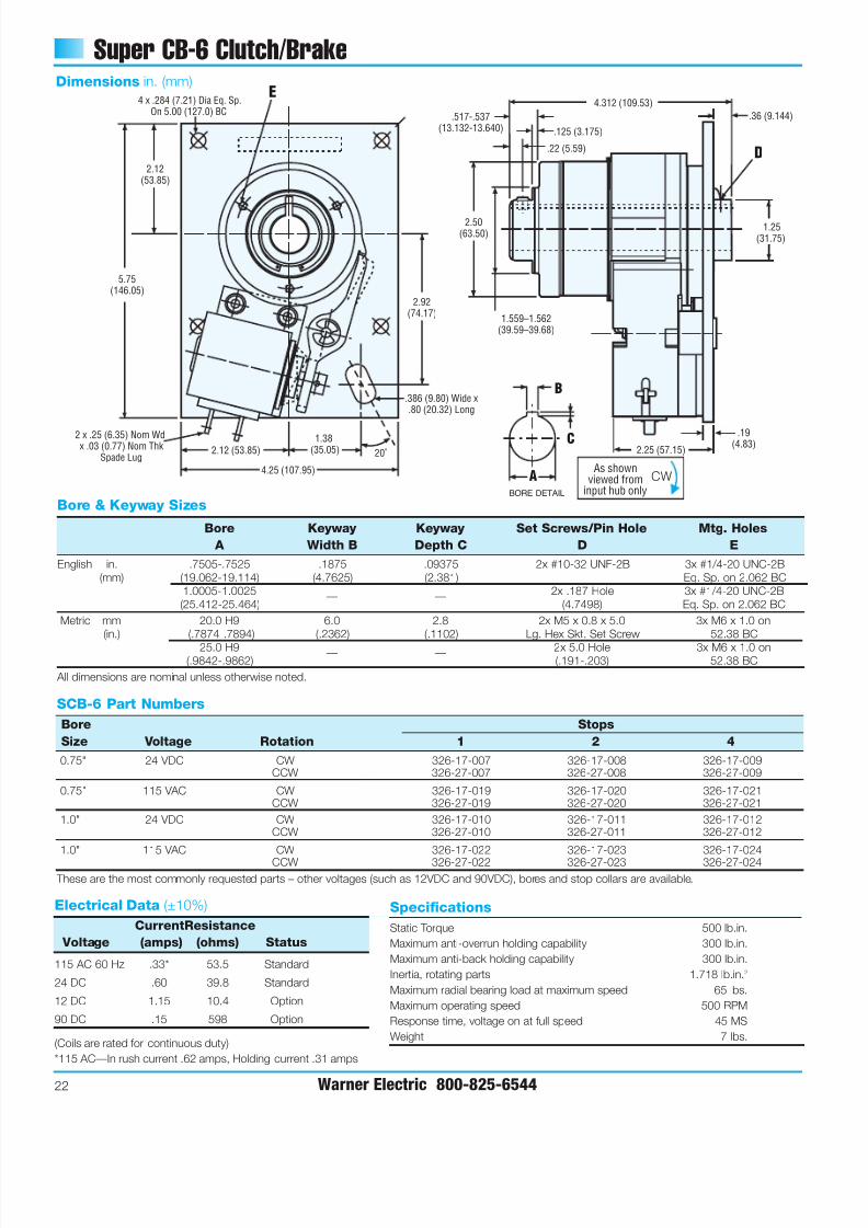
CB-6 Clutch/Brake
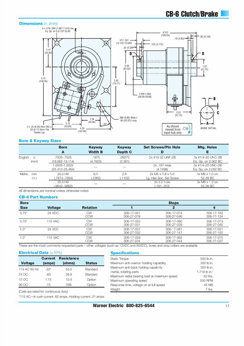
Warner Electric 800-825-6544 17
+
+
+ +
+ +
+ + +
+
4.312(109.53)
.517-.537(13.132-13.640) .125 (3.175)
.22 (5.59)
.36 (9.144).19 (4.83)
2.50(63.50)
1.559-1.562(39.59-39.68)
1.25(31.75)
2.25(57.15)
2.92(74.17)
5.75(146.05)
2.12(53.85)
4.25(107.95)
1.38
(35.05)
2.12(53.85)
4 x .279-.288 (7.087-7.315) DiaEq. Sp. on 5.0 (127.0) BC E
20°
DD
2 x .25 (6.35) Nom Wd x.03 (0.77) Nom Thk
Spade Lug
.386 (9.80) Wide x
.80 (20.32) Long
Dimensions in. (mm)
Specifications
Static Torque 500 lb.in.
Maximum anti-overrun holding capability 300 lb.in.
Maximum anti-back holding capability 300 lb.in.
Inertia, rotating parts 1.718 lb.in.2
Maximum radial bearing load at maximum speed 63 lbs.
Maximum operating speed 500 RPM
Response time, voltage on at full speed 45 MS
Weight 7 lbs.
Bore & Keyway Sizes
Bore Keyway Keyway Set Screws/Pin Hole Mtg. Holes
A Width B Depth C D E
English in. .7505-.7525 .1875 .09375 2x #10-32 UNF-2B 3x #1/4-20 UNC-2B
(mm) (19.062-19.114) (4.7625) (2.381) Eq. Sp. on 2.062 BC
1.0005-1.0025 2x .187 Hole 3x #1/4-20 UNC-2B
(25.412-25.464)— —
(4.7498) Eq. Sp. on 2.062 BC
Metric mm 20.0 H9 6.0 2.8 2x M5 x 0.8 x 5.0 3x M6 x 1.0 on
(in.) (.7874-.7894) (.2362) (.1102) Lg. Hex Soc. Set Screw 52.38 BC
25.0 H9 2x 5.0 Hole 3x M6 x 1.0 on(.9842-.9862)
— —(.191-.203) 52.38 BC
All dimensions are nominal unless otherwise noted.
Electrical Data (±10%)
Current Resistance
Voltage (amps) (ohms) Status
115 AC 60 Hz .33* 53.5 Standard
24 DC .60 39.9 Standard
12 DC 1.15 10.4 Option
90 DC .15 598 Option
(Coils are rated for continuous duty)
*115 AC—In rush current .62 amps, Holding current .31 amps
CB-6 Part Numbers
Bore Stops
Size Voltage Rotation 1 2 4
0.75" 24 VDC CW 306-17-051 306-17-074 306-17-162CCW 306-27-029 306-27-046 306-27-134
0.75" 115 VAC CW 306-17-053 306-17-060 306-17-073CCW 306-27-031 306-27-039 306-27-045
1.0" 24 VDC CW 306-17-057 306-17-061 306-17-031CCW 306-27-032 306-27-147 306-27-150
1.0" 115 VAC CW 306-17-059 306-17-062 306-17-075
CCW 306-27-034 306-27-044 306-27-037 These are the most commonly requested parts – other voltages (such as 12VDC and 90VDC), bores and stop collars are available.
As shownviewed from
input hub onlyCW BORE DETAIL
C
B
A
7/21/2019 EMBRAGUE FRENO RESORTES
http://slidepdf.com/reader/full/embrague-freno-resortes 20/40
7/21/2019 EMBRAGUE FRENO RESORTES
http://slidepdf.com/reader/full/embrague-freno-resortes 21/40
Super CB Series Clutch/Brakes
Warner Electric 800-825-6544 19
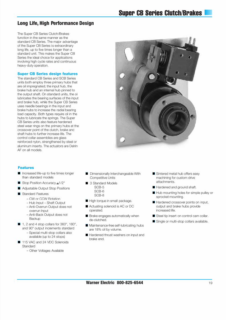
Long Life, High Performance Design
The Super CB Series Clutch/Brakes
function in the same manner as the
standard CB Series. The major advantage
of the Super CB Series is extraordinary
long life, up to five times longer than a
standard unit. This makes the Super CB
Series the ideal choice for applications
involving high cycle rates and continuous
heavy-duty operation.
Super CB Series design features
The standard CB Series and SCB Series
units both employ three primary hubs that
are oil impregnated; the input hub, the
brake hub and an internal hub pinned to
the output shaft. On standard units, the oil
lubricates the bearing surfaces of the input
and brake hub, while the Super CB Series
uses needle bearings in the input and
brake hubs to increase the radial bearing
load capacity. Both types require oil in the
hubs to lubricate the springs. The Super
CB Series units also feature hardened
steel wear rings on the primary hubs at the
crossover point of the clutch, brake and
shaft hubs to further increase life. The
control collar assemblies are glass
reinforced nylon, strengthened by steel or
aluminum inserts. The actuators are Delrin ‚
AF on all models.
Features■ Increased life-up to five times longer
than standard models
■ Stop Position Accuracy +1/2°
■ Adjustable Output Stop Positions
■ Standard Features
– CW or CCW Rotation
– Hub Input – Shaft Output
– Anti-Overrun Output does not
overrun Input
– Anti-Back Output does not
Backup
■ 1, 2 and 4 stop collars for 360°, 180°,and 90° output increments standard
– Special multi-stop collars also
available (up to 24 stops)
■ 115 VAC and 24 VDC Solenoids
Standard
– Other Voltages Available
■ Dimensionally Interchangeable With
Competitive Units
■ 3 Standard Models
SCB-5
SCB-6
SCB-8
■ High torque in small package.
■ Actuating solenoid is AC or DC
operated.
■ Brake engages automatically when
de-clutched.
■ Maintenance-free self-lubricating hubsare 18% oil by volume.
■ Hardened thrust washers on input and
brake end.
■ Sintered metal hub offers easy
machining for custom drive
attachments.
■ Hardened and ground shaft.
■ Hub mounting holes for simple pulley o
sprocket mounting.
■ Hardened crossover points on input,
output and brake hubs provide
increased life.
■ Steel tip insert on control cam collar.
■ Single or multi-stop collars available.
7/21/2019 EMBRAGUE FRENO RESORTES
http://slidepdf.com/reader/full/embrague-freno-resortes 22/40
7/21/2019 EMBRAGUE FRENO RESORTES
http://slidepdf.com/reader/full/embrague-freno-resortes 23/40
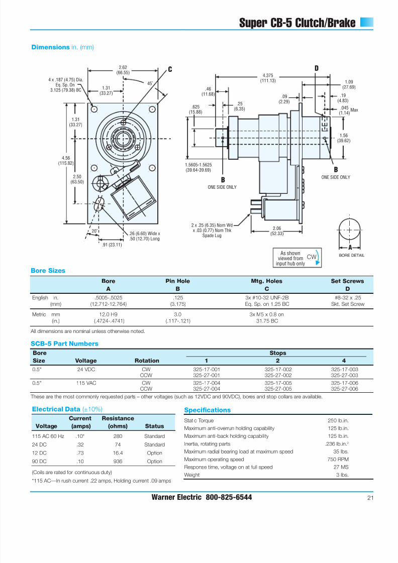
Super CB-5 Clutch/Brake
Warner Electric 800-825-6544 21
4 x .187 (4.75) Dia.Eq. Sp. On
3.125 (79.38) BC
2.62(66.55)
1.31(33.27)
1.31(33.27)
45˚
2.50(63.50)
4.56(115.82)
20˚
.91 (23.11)
.46(11.68)
.25(6.35)
4.375(111.13)
.09(2.29)
1.09(27.69)
.19(4.83)
.045(1.14)
1.56(39.62)
2.06(52.33)
.625(15.88)
DC
B
Max
1.5605-1.5625(39.64-39.69)
ONE SIDE ONLY
BONE SIDE ONLY
.26 (6.60) Wide x.50 (12.70) Long
2 x .25 (6.35) Nom Wdx .03 (0.77) Nom Thk
Spade Lug
Dimensions in. (mm)
Specifications
Static Torque 250 lb.in.
Maximum anti-overrun holding capability 125 lb.in.
Maximum anti-back holding capability 125 lb.in.
Inertia, rotating parts .236 lb.in.2
Maximum radial bearing load at maximum speed 35 lbs.
Maximum operating speed 750 RPM
Response time, voltage on at full speed 27 MS
Weight 3 lbs.
Electrical Data (±10%)
Current Resistance
Voltage (amps) (ohms) Status
115 AC 60 Hz .10* 280 Standard
24 DC .32 74 Standard
12 DC .73 16.4 Option
90 DC .10 936 Option
(Coils are rated for continuous duty)
*115 AC—In rush current .22 amps, Holding current .09 amps
SCB-5 Part Numbers
Bore Stops
Size Voltage Rotation 1 2 4
0.5" 24 VDC CW 325-17-001 325-17-002 325-17-003CCW 325-27-001 325-27-002 325-27-003
0.5" 115 VAC CW 325-17-004 325-17-005 325-17-006CCW 325-27-004 325-27-005 325-27-006
These are the most commonly requested parts – other voltages (such as 12VDC and 90VDC), bores and stop collars are available.
As shownviewed from
input hub onlyCW BORE DETAIL
A
Bore Sizes
Bore Pin Hole Mtg. Holes Set Screws
A B C D
English in. .5005-.5025 .125 3x #10-32 UNF-2B #8-32 x .25(mm) (12.712-12.764) (3.175) Eq. Sp. on 1.25 BC Skt. Set Screw
Metric mm 12.0 H9 3.0 3x M5 x 0.8 on
(in.) (.4724-.4741) (.117-.121) 31.75 BC
All dimensions are nominal unless otherwise noted.
7/21/2019 EMBRAGUE FRENO RESORTES
http://slidepdf.com/reader/full/embrague-freno-resortes 24/40
7/21/2019 EMBRAGUE FRENO RESORTES
http://slidepdf.com/reader/full/embrague-freno-resortes 25/40
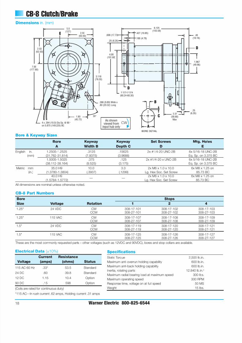
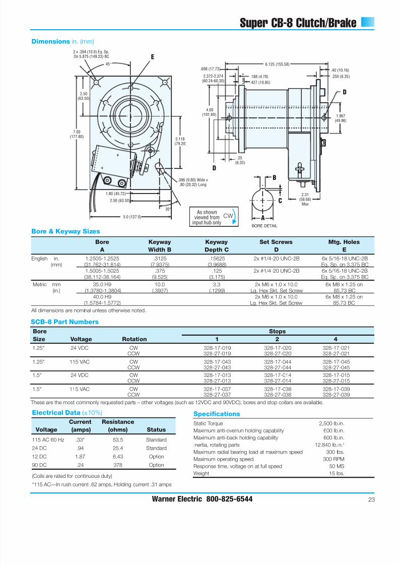
Super CB-8 Clutch/Brake
Warner Electric 800-825-6544 23
+
+
+
+ +
+
+ +
+ + +
+
E
D
D
2 x .394 (10.0) Eq. Sp.On 5.875 (149.23) BC
3.118(79.20)
2.50
(63.50)
7.00(177.80)
1.80 (45.72)
5.0 (127.0)
2.50 (63.50)
30°
45° 6.125 (155.58)
.427 (10.85)
.698 (17.73)
.188 (4.78)
.40 (10.16)
.250 (6.35)
1.967(49.96)
.25(6.35)
4.00(101.60)
2.372-2.374(60.24-60.30)
2.31(58.68)
Max
.386 (9.80) Wide x.80 (20.32) Long
Dimensions in. (mm)
Specifications
Static Torque 2,500 lb.in.
Maximum anti-overrun holding capability 600 lb.in.
Maximum anti-back holding capability 600 lb.in.
Inertia, rotating parts 12.840 lb.in.2
Maximum radial bearing load at maximum speed 300 lbs.
Maximum operating speed 300 RPM
Response time, voltage on at full speed 50 MS
Weight 15 lbs.
Bore & Keyway Sizes
Bore Keyway Keyway Set Screws Mtg. Holes
A Width B Depth C D E
English in. 1.2505-1.2525 .3125 .15625 2x #1/4-20 UNC-2B 6x 5/16-18 UNC-2B
(mm) (31.762-31.814) (7.9375) (3.9688) Eq. Sp. on 3.375 BC
1.5005-1.5025 .375 .125 2x #1/4-20 UNC-2B 6x 5/16-18 UNC-2B
(38.112-38.164) (9.525) (3.175) Eq. Sp. on 3.375 BC
Metric mm 35.0 H9 10.0 3.3 2x M6 x 1.0 x 10.0 6x M8 x 1.25 on
(in.) (1.3780-1.3804) (.3937) (.1299) Lg. Hex Skt. Set Screw 85.73 BC
40.0 H9 2x M6 x 1.0 x 10.0 6x M8 x 1.25 on(1.5784-1.5772)
— —Lg. Hex Skt. Set Screw 85.73 BC
All dimensions are nominal unless otherwise noted.
Electrical Data (±10%)
Current Resistance
Voltage (amps) (ohms) Status
115 AC 60 Hz .33* 53.5 Standard
24 DC .94 25.4 Standard
12 DC 1.87 6.43 Option
90 DC .24 378 Option
(Coils are rated for continuous duty)
*115 AC—In rush current .62 amps, Holding current .31 amps
SCB-8 Part Numbers
Bore Stops
Size Voltage Rotation 1 2 4
1.25" 24 VDC CW 328-17-019 328-17-020 328-17-021CCW 328-27-019 328-27-020 328-27-021
1.25" 115 VAC CW 328-17-043 328-17-044 328-17-045CCW 328-27-043 328-27-044 328-27-045
1.5" 24 VDC CW 328-17-013 328-17-014 328-17-015CCW 328-27-013 328-27-014 328-27-015
1.5" 115 VAC CW 328-17-037 328-17-038 328-17-039
CCW 328-27-037 328-27-038 328-27-039 These are the most commonly requested parts – other voltages (such as 12VDC and 90VDC), bores and stop collars are available.
As shownviewed from
input hub onlyCW
BORE DETAIL
C
B
A
7/21/2019 EMBRAGUE FRENO RESORTES
http://slidepdf.com/reader/full/embrague-freno-resortes 26/40
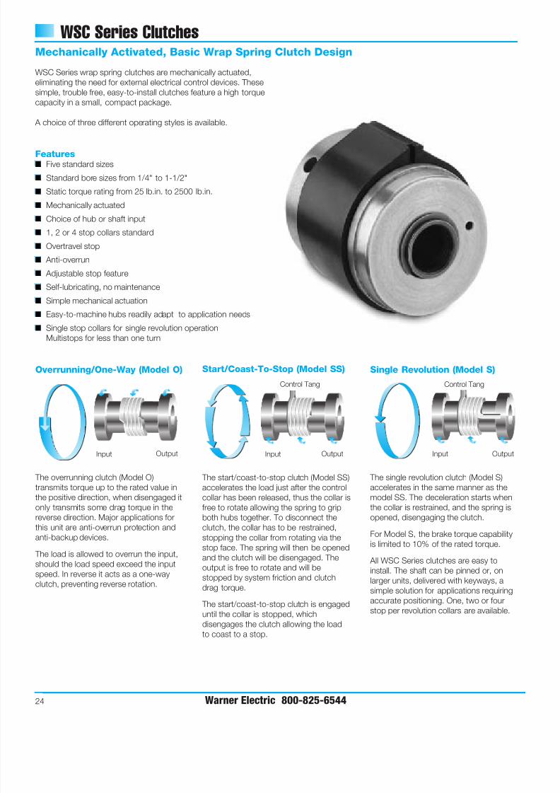
WSC Series Clutches
24 Warner Electric 800-825-6544
WSC Series wrap spring clutches are mechanically actuated,
eliminating the need for external electrical control devices. These
simple, trouble free, easy-to-install clutches feature a high torque
capacity in a small, compact package.
A choice of three different operating styles is available.
Features■ Five standard sizes
■ Standard bore sizes from 1/4" to 1-1/2"
■ Static torque rating from 25 lb.in. to 2500 lb.in.
■ Mechanically actuated
■ Choice of hub or shaft input
■ 1, 2 or 4 stop collars standard
■ Overtravel stop
■ Anti-overrun
■
Adjustable stop feature■ Self-lubricating, no maintenance
■ Simple mechanical actuation
■ Easy-to-machine hubs readily adapt to application needs
■ Single stop collars for single revolution operation
Multistops for less than one turn
Mechanically Activated, Basic Wrap Spring Clutch Design
Single Revolution (Model S)
The single revolution clutch (Model S)
accelerates in the same manner as the
model SS. The deceleration starts when
the collar is restrained, and the spring is
opened, disengaging the clutch.
For Model S, the brake torque capability
is limited to 10% of the rated torque.
All WSC Series clutches are easy to
install. The shaft can be pinned or, on
larger units, delivered with keyways, a
simple solution for applications requiring
accurate positioning. One, two or four
stop per revolution collars are available.
Input Output
Control Tang
Overrunning/One-Way (Model O)
The overrunning clutch (Model O)
transmits torque up to the rated value in
the positive direction, when disengaged it
only transmits some drag torque in the
reverse direction. Major applications for
this unit are anti-overrun protection and
anti-backup devices.
The load is allowed to overrun the input,should the load speed exceed the input
speed. In reverse it acts as a one-way
clutch, preventing reverse rotation.
Input Output
Start/Coast-To-Stop (Model SS)
The start/coast-to-stop clutch (Model SS)
accelerates the load just after the control
collar has been released, thus the collar is
free to rotate allowing the spring to grip
both hubs together. To disconnect the
clutch, the collar has to be restrained,
stopping the collar from rotating via the
stop face. The spring will then be opened
and the clutch will be disengaged. Theoutput is free to rotate and will be
stopped by system friction and clutch
drag torque.
The start/coast-to-stop clutch is engaged
until the collar is stopped, which
disengages the clutch allowing the load
to coast to a stop.
Input Output
Control Tang
7/21/2019 EMBRAGUE FRENO RESORTES
http://slidepdf.com/reader/full/embrague-freno-resortes 27/40
7/21/2019 EMBRAGUE FRENO RESORTES
http://slidepdf.com/reader/full/embrague-freno-resortes 28/40
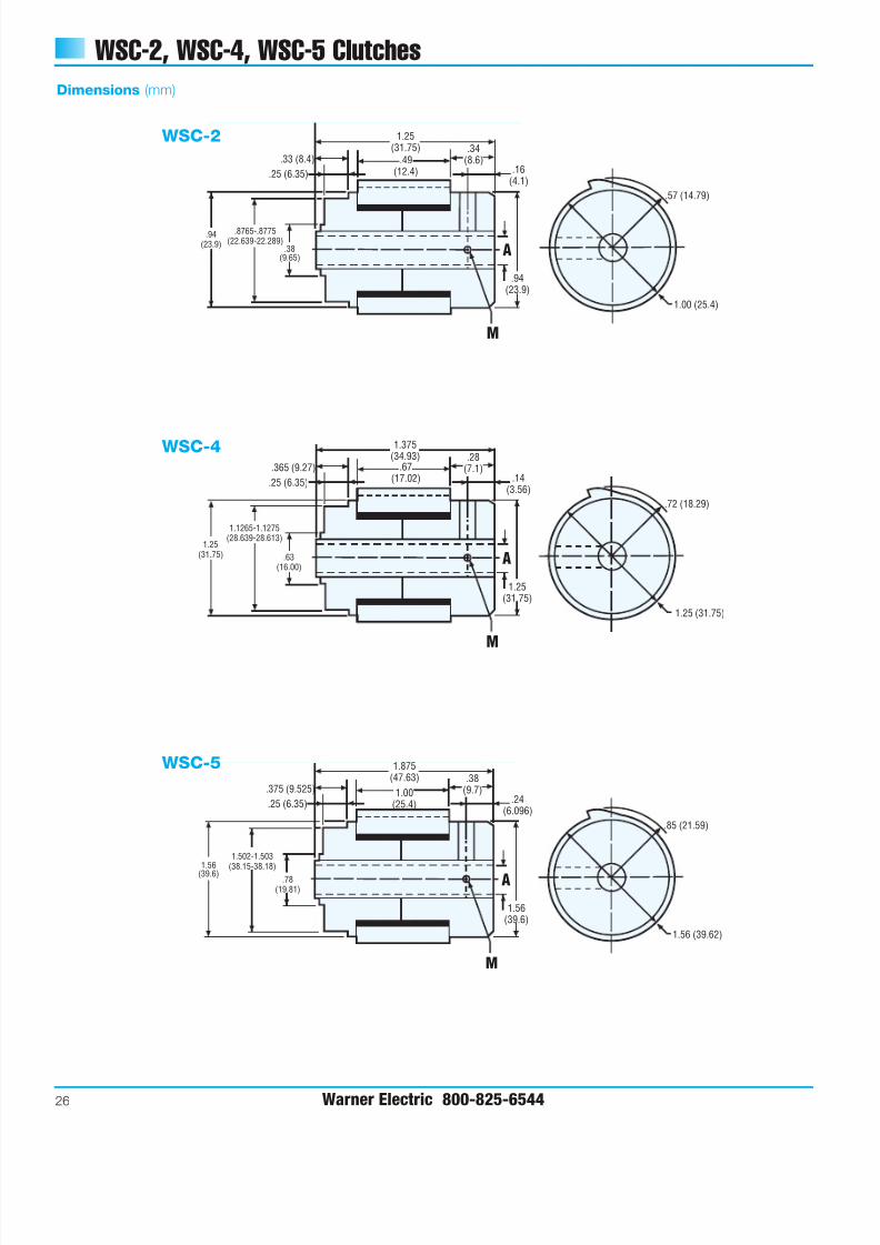
WSC-2, WSC-4, WSC-5 Clutches
26 Warner Electric 800-825-6544
Dimensions (mm)
1.25(31.75)
.94(23.9)
A
.94(23.9)
.33 (8.4)
.25 (6.35) .16(4.1)
.57 (14.79)
1.00 (25.4)
M
.49(12.4)
.34(8.6)
.38(9.65)
.8765-.8775(22.639-22.289)
1.375(34.93)
1.25(31.75)
A
1.25(31.75)
.365 (9.27)
.25 (6.35) .14(3.56)
.72 (18.29)
1.25 (31.75)
M
.67(17.02)
.28(7.1)
.63(16.00)
1.1265-1.1275(28.639-28.613)
1.875(47.63)
1.56(39.6)
A
1.56
(39.6)
.375 (9.525)
.25 (6.35) .24(6.096)
.85 (21.59)
1.56 (39.62)
M
1.00(25.4)
.38(9.7)
.78(19.81)
1.502-1.503(38.15-38.18)
WSC-2
WSC-4
WSC-5

7/21/2019 EMBRAGUE FRENO RESORTES
http://slidepdf.com/reader/full/embrague-freno-resortes 29/40
7/21/2019 EMBRAGUE FRENO RESORTES
http://slidepdf.com/reader/full/embrague-freno-resortes 30/40
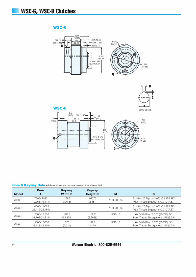
WSC-6, WSC-8 Clutches
28 Warner Electric 800-825-6544
.774 (19.66)
.124 (3.15)
2.311(58.70)
.866(22.00).280 (7.11)
.671 (17.04)
M
1.559-1.562(39.60-39.67)
2.437(61.90)
2.696(68.48)
1.500(38.10)
.286 (7.26)
Q
+
+ +
+
+ + 3.75(95.25)
2.00(50.8)
Q
1.98(50.3)
M
3.5(88.9)
.30(7.62)
.522 (13.26) .18(4.57)
4.00(101.6)
2.374-2.376(60.300-60.350)
WSC-6
WSC-8
Bore & Keyway Data All dimensions are nominal unless otherwise noted.
Bore Keyway Keyway
Model A Width B Height C M Q.7505-.7525 .1885 .09375 3x #1/4-20 Tap on 2.062 (52.375) BC
WSC-6(19.063-19.114) (4.788) (2.381)
#1/4-20 TapMax. Thread Engagement .310 (7.87)
1.0005-1.0025 3x #1/4-20 Tap on 2.062 (52.375) BCWSC-6
(25.412-25.464)— — #1/4-20 Tap
Max. Thread Engagement .310 (7.87)
1.2505-1.2530 .3125 .15625 3/16-16 6x 5/16-18 on 3.375 (85.725) BCWSC-8
(31.762-31.814) (7.9375) (3.9688) Max. Thread Engagement .375 (9.53)
1.5005-1.5030 .375 .125 3/16-16 6x 5/16-18 on 3.375 (85.725) BCWSC-8
(38.113-38.176) (9.525) (3.175) Max. Thread Engagement .375 (9.53)
BORE DETAIL
C
B
A
7/21/2019 EMBRAGUE FRENO RESORTES
http://slidepdf.com/reader/full/embrague-freno-resortes 31/40
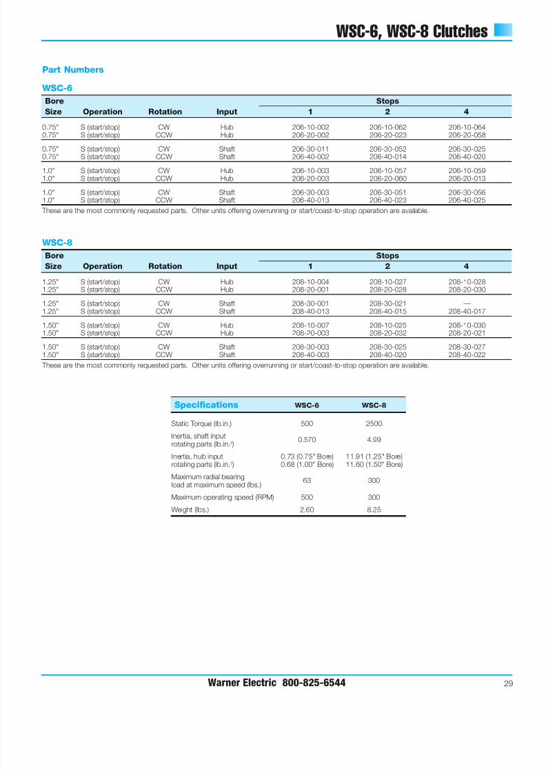
WSC-6, WSC-8 Clutches
Warner Electric 800-825-6544 29
Specifications WSC-6 WSC-8
Static Torque (lb.in.) 500 2500
Inertia, shaft input0.570 4.99
rotating parts (lb.in.2 )
Inertia, hub input 0.73 (0.75" Bore) 11.91 (1.25" Bore)rotating parts (lb.in.2 ) 0.68 (1.00" Bore) 11.60 (1.50" Bore)
Maximum radial bearing63 300
load at maximum speed (lbs.)
Maximum operating speed (RPM) 500 300
Weight (lbs.) 2.60 8.25
WSC-6
Bore Stops
Size Operation Rotation Input 1 2 4
0.75" S (start/stop) CW Hub 206-10-002 206-10-062 206-10-064
0.75" S (start/stop) CCW Hub 206-20-002 206-20-023 206-20-058
0.75" S (start/stop) CW Shaft 206-30-011 206-30-052 206-30-0250.75" S (start/stop) CCW Shaft 206-40-002 206-40-014 206-40-020
1.0" S (start/stop) CW Hub 206-10-003 206-10-057 206-10-0591.0" S (start/stop) CCW Hub 206-20-003 206-20-060 206-20-013
1.0" S (start/stop) CW Shaft 206-30-003 206-30-051 206-30-0561.0" S (start/stop) CCW Shaft 206-40-013 206-40-023 206-40-025
These are the most commonly requested parts. Other units offering overrunning or start/coast-to-stop operation are available.
WSC-8
Bore Stops
Size Operation Rotation Input 1 2 4
1.25" S (start/stop) CW Hub 208-10-004 208-10-027 208-10-0281.25" S (start/stop) CCW Hub 208-20-001 208-20-028 208-20-030
1.25" S (start/stop) CW Shaft 208-30-001 208-30-021 —1.25" S (start/stop) CCW Shaft 208-40-013 208-40-015 208-40-017
1.50" S (start/stop) CW Hub 208-10-007 208-10-025 208-10-0301.50" S (start/stop) CCW Hub 208-20-003 208-20-032 208-20-021
1.50" S (start/stop) CW Shaft 208-30-003 208-30-025 208-30-0271.50" S (start/stop) CCW Shaft 208-40-003 208-40-020 208-40-022
These are the most commonly requested parts. Other units offering overrunning or start/coast-to-stop operation are available.
Part Numbers
7/21/2019 EMBRAGUE FRENO RESORTES
http://slidepdf.com/reader/full/embrague-freno-resortes 32/40
Power Supply Units
30 Warner Electric 800-825-6544
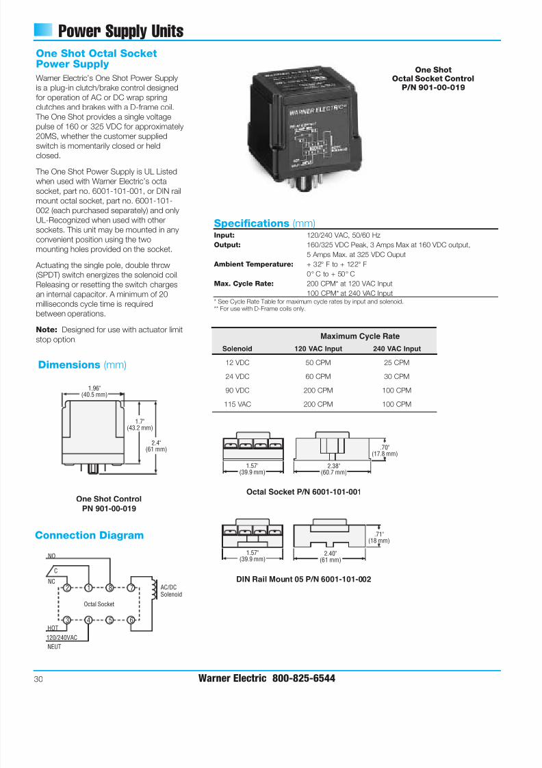
Specifications (mm)Input: 120/240 VAC, 50/60 Hz
Output: 160/325 VDC Peak, 3 Amps Max at 160 VDC output,
5 Amps Max. at 325 VDC Ouput
Ambient Temperature: + 32° F to + 122° F
0° C to + 50° C
Max. Cycle Rate: 200 CPM* at 120 VAC Input
100 CPM* at 240 VAC Input* See Cycle Rate Table for maximum cycle rates by input and solenoid.** For use with D-Frame coils only.
Solenoid 120 VAC Input 240 VAC Input
12 VDC 50 CPM 25 CPM
24 VDC 60 CPM 30 CPM
90 VDC 200 CPM 100 CPM
115 VAC 200 CPM 100 CPM
One Shot Octal SocketPower Supply
Warner Electric’s One Shot Power Supply
is a plug-in clutch/brake control designed
for operation of AC or DC wrap spring
clutches and brakes with a D-frame coil.
The One Shot provides a single voltage
pulse of 160 or 325 VDC for approximately
20MS, whether the customer suppliedswitch is momentarily closed or held
closed.
The One Shot Power Supply is UL Listed
when used with Warner Electric’s octal
socket, part no. 6001-101-001, or DIN rail
mount octal socket, part no. 6001-101-
002 (each purchased separately) and only
UL-Recognized when used with other
sockets. This unit may be mounted in any
convenient position using the two
mounting holes provided on the socket.
Actuating the single pole, double throw(SPDT) switch energizes the solenoid coil.
Releasing or resetting the switch charges
an internal capacitor. A minimum of 20
milliseconds cycle time is required
between operations.
Note: Designed for use with actuator limit
stop option.
Dimensions (mm)
Connection Diagram
Octal Socket P/N 6001-101-001One Shot Control
PN 901-00-019
DIN Rail Mount 05 P/N 6001-101-002
One ShotOctal Socket Control
P/N 901-00-019
1
4 5
8
6
7
3
2
Octal Socket
NO
NC
C
HOT
NEUT
120/240VAC
AC/DCSolenoid
1.96"(40.5 mm)
1.7"(43.2 mm)
2.4"(61 mm)
1.57"(39.9 mm)
2.38"(60.7 mm)
.70"(17.8 mm)
1.57"(39.9 mm)
2.40"(61 mm)
.71"(18 mm)
Maximum Cycle Rate
7/21/2019 EMBRAGUE FRENO RESORTES
http://slidepdf.com/reader/full/embrague-freno-resortes 33/40
Power Supply Units
Warner Electric 800-825-6544 31
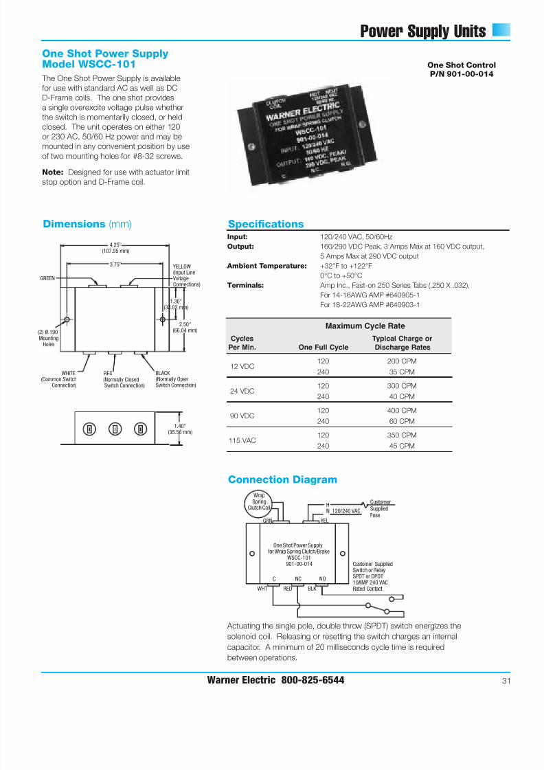
One Shot Power Supply Model WSCC-101
The One Shot Power Supply is available
for use with standard AC as well as DC
D-Frame coils. The one shot provides
a single overexcite voltage pulse whether
the switch is momentarily closed, or held
closed. The unit operates on either 120
or 230 AC, 50/60 Hz power and may bemounted in any convenient position by use
of two mounting holes for #8-32 screws.
Note: Designed for use with actuator limit
stop option and D-Frame coil.
Dimensions (mm) Specifications
Actuating the single pole, double throw (SPDT) switch energizes the
solenoid coil. Releasing or resetting the switch charges an internal
capacitor. A minimum of 20 milliseconds cycle time is required
between operations.
MountingHoles
(2) Ø.190
3.75"
4.25"(107.95 mm)
1.30"(33.02 mm)
2.50"(66.04 mm)
GREEN
WHITE(Common Switch
Connection)
YELLOW(Input Line VoltageConnections)
RED(Normally ClosedSwitch Connection)
BLACK (Normally OpenSwitch Connection)
1.40"(35.56 mm)
Connection Diagram
NC NOC
WrapSpring
Clutch Coil120/240 VAC
HN
One Shot Power Supplyfor Wrap Spring Clutch/Brake
WSCC-101901-00-014
YELGRN
WHT RED BLK
Customer SuppliedSwitch or RelaySPDT or DPDT10AMP 240 VACRated Contact
CustomerSuppliedFuse
One Shot ControlP/N 901-00-014
Input: 120/240 VAC, 50/60Hz
Output: 160/290 VDC Peak, 3 Amps Max at 160 VDC output,
5 Amps Max at 290 VDC output
Ambient Temperature: +32°F to +122°F
0°C to +50°C
Terminals: Amp Inc., Fast-on 250 Series Tabs (.250 X .032),
For 14-16AWG AMP #640905-1
For 18-22AWG AMP #640903-1
Cycles Typical Charge or
Per Min. One Full Cycle Discharge Rates
12 VDC120 200 CPM
240 35 CPM
24 VDC120 300 CPM
240 40 CPM
90 VDC120 400 CPM
240 60 CPM
115 VAC120 350 CPM
240 45 CPM
Maximum Cycle Rate
7/21/2019 EMBRAGUE FRENO RESORTES
http://slidepdf.com/reader/full/embrague-freno-resortes 34/40
Application Engineering
32 Warner Electric 800-825-6544
Selection Considerations
Application Analysis
1. Function
The process for establishing the clutch
or brake function is illustrated in Step 1
on page 4. In review, the three functions
and the appropriate series selections
are noted below.
Overrunning (One Way Clutch)
Unidirectional torque transmission with
free wheeling in opposite direction.
Selection
WSC (Model O)
Start/Coast-to-Stop
(Random Positioning)
Engage/disengage with random stop
position.
Selection
WSC (Model SS)
Start/Stop (Single Revolution)
Accurate stop position in single or
fraction revolution cycles.
Selection
WSC (Model S)
Standard CB
Super CB
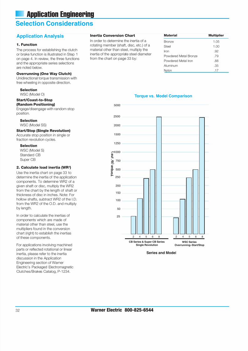
2. Calculate load inertia (WR2 )
Use the inertia chart on page 33 to
determine the inertia of the application
components. To determine WR2 of a
given shaft or disc, multiply the WR2
from the chart by the length of shaft or
thickness of disc in inches. Note: For
hollow shafts, subtract WR2 of the I.D.
from the WR2 of the O.D. and multiply
by length.
In order to calculate the inertias of
components which are made of
material other than steel, use the
multipliers found in the conversion
chart (right) to establish the inertias
of these components.
For applications involving machinedparts or reflected rotational or linear
inertia, please refer to the inertia
discussion in the Application
Engineering section of Warner
Electric’s Packaged Electromagnetic
Clutches/Brakes Catalog, P-1234.
Inertia Conversion Chart
In order to determine the inertia of a
rotating member (shaft, disc, etc.) of a
material other than steel, multiply the
inertia of the appropriate steel diameter
from the chart on page 33 by:
Material Multiplier
Bronze 1.05
Steel 1.00
Iron .92
Powdered Metal Bronze .79
Powdered Metal Iron .88 Aluminum .35
Nylon .17
25
50
100
150
200
250
500
750
1000
1250
1500
2000
2500
5000
T o
r q
u e
( l b
. i n
s . )
2 4 5 6 8
CB Series & Super CB Series
Single Revolution
2 4 5 6 8
WSC Series
Overrunning–Start/Stop
Series and Model
Torque vs. Model Comparison
7/21/2019 EMBRAGUE FRENO RESORTES
http://slidepdf.com/reader/full/embrague-freno-resortes 35/40
Application Engineering
Warner Electric 800-825-6544 33
Selection Considerations
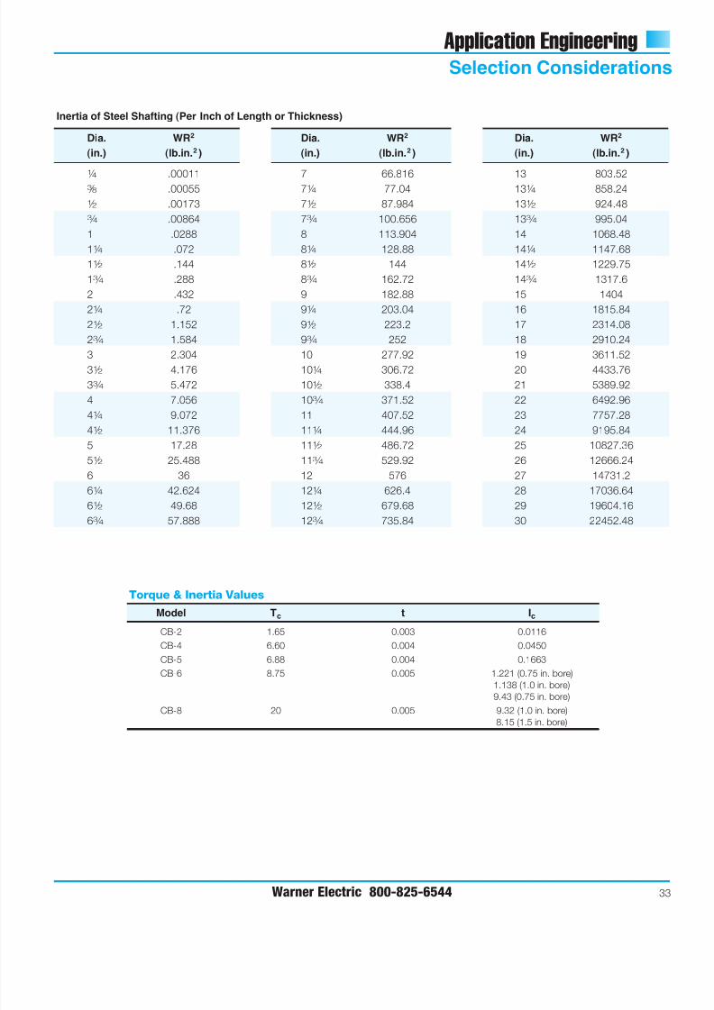
Inertia of Steel Shafting (Per Inch of Length or Thickness)
Dia. WR2
(in.) (lb.in.2 )
1
⁄ 4 .000113 ⁄ 8 .00055
1 ⁄ 2 .00173
3 ⁄ 4 .00864
1 .0288
11 ⁄ 4 .072
11 ⁄ 2 .144
13 ⁄ 4 .288
2 .432
21 ⁄ 4 .72
21 ⁄ 2 1.152
23 ⁄ 4 1.584
3 2.30431 ⁄ 2 4.176
33 ⁄ 4 5.472
4 7.056
41 ⁄ 4 9.072
41 ⁄ 2 11.376
5 17.28
51 ⁄ 2 25.488
6 36
61 ⁄ 4 42.624
61 ⁄ 2 49.68
63 ⁄ 4 57.888
Dia. WR2
(in.) (lb.in.2 )
7 66.81671 ⁄ 4 77.04
71 ⁄ 2 87.984
73 ⁄ 4 100.656
8 113.904
81 ⁄ 4 128.88
81 ⁄ 2 144
83 ⁄ 4 162.72
9 182.88
91 ⁄ 4 203.04
91 ⁄ 2 223.2
93 ⁄ 4 252
10 277.92101 ⁄ 4 306.72
101 ⁄ 2 338.4
103 ⁄ 4 371.52
11 407.52
111 ⁄ 4 444.96
111 ⁄ 2 486.72
113 ⁄ 4 529.92
12 576
121 ⁄ 4 626.4
121 ⁄ 2 679.68
123 ⁄ 4 735.84
Dia. WR2
(in.) (lb.in.2 )
13 803.52131 ⁄ 4 858.24
131 ⁄ 2 924.48
133 ⁄ 4 995.04
14 1068.48
141 ⁄ 4 1147.68
141 ⁄ 2 1229.75
143 ⁄ 4 1317.6
15 1404
16 1815.84
17 2314.08
18 2910.24
19 3611.5220 4433.76
21 5389.92
22 6492.96
23 7757.28
24 9195.84
25 10827.36
26 12666.24
27 14731.2
28 17036.64
29 19604.16
30 22452.48
Model Tc t Ic
CB-2 1.65 0.003 0.0116
CB-4 6.60 0.004 0.0450
CB-5 6.88 0.004 0.1663
CB-6 8.75 0.005 1.221 (0.75 in. bore)
1.138 (1.0 in. bore)
9.43 (0.75 in. bore)
CB-8 20 0.005 9.32 (1.0 in. bore)8.15 (1.5 in. bore)
Torque & Inertia Values
7/21/2019 EMBRAGUE FRENO RESORTES
http://slidepdf.com/reader/full/embrague-freno-resortes 36/40
Application Engineering
Selection Considerations
34 Warner Electric 800-825-6544
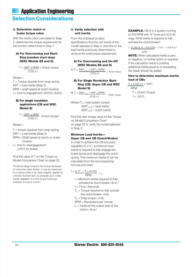
3. Determine clutch or
brake torque value
With the inertia value calculated in Step
2, determine the torque requirement for
the function determined in Step 1.
A) For Overrunning and Start-
Stop (random start-stop)
(WSC Models SS and O)
T = WR2 x RPM + friction torque
3700 x t
Where—
T = Torque required from wrap spring
WR2 = load inertia (Step 2)
RPM = shaft speed at clutch location
t = time to engagement (.003 for clutch)
B) For single revolution
applications (CB and WSC
Model S)
T = WR2 x RPM– friction torque*
3700 x t
Where—
T = torque required from wrap spring
WR2 = Load inertia (Step 2)
RPM = Shaft speed at clutch or brake
location
t = time to disengagement(.0015 for brake)
Find the value of T on the Torque vs.
Model Comparison Chart on page 32.
*Frictional (drag) torque is the torque necessary
to overcome static friction. It may be measured
by a spring-scale or by dead-weights, applied to
a known moment arm so gradually as to make
inertia negligible. It is that torque found just
sufficient to induce motion.
4. Verify selection with
unit inertia
From the individual product
specifications find the unit inertia of the
model selected in Step 3. Add this to the
load inertia previously determined to
arrive at the total torque requirement.
A) For Overrunning and On-Off
(WSC Models SS and O)
A) T t = (WR2LOAD + WR2
UNIT )RPM
3700 x t
B) For Single Revolution Start-
Stop (CB, Super CB and WSC
Model S)
B) T t = (WR2LOAD + WR2
UNIT )RPM
3700 x t
Where–T t = total system torque
(WR2LOAD ) = load inertia
(WR2UNIT ) = clutch inertia
Find this new torque value on the Torque
vs. Model Comparison Chart
on page 32 to verify the model selected
in Step 3.
Minimum Load Inertia—
Super CB and CB Clutch/Brakes
In order to achieve the CB accuracy
capability of ±1 / 2°, a minimum loadinertia is required to fully engage the
brake spring and disengage the clutch
spring. This minimum inertia (l) can be
calculated from the accompanying
formula and chart:
l = (t) (T c + T o ) (3700)– Ic
RPM
l = Minimum inertia required to fully
activate the clutch/brake—lb.in.2
t = Time—Seconds
T c = Torque required to fully activate
the clutch/brake—in.lb. T o = Drag torque—in.lb.
RPM = Revolutions per minute
Ic = Inertia at the output side of the
clutch—lb.in.2
EXAMPLE: CB-6 in a system running
at 200 RPM with 3 ⁄ 4" bore and 20 in.lb.
drag. What inertia is required to fully
activate the clutch/brake?
I = (0.005) (8.75 + 20) (3700) – 1.221 = 1.438 lb.in.
2
(200)
NOTE: When calculated inertia is zero
or negative, no further action is required.
If the calculation result is positive,
additional inertia equal to or exceeding
the result should be added.
How to determine maximum inertia
load of CBs
T x 3700 x t = WR2
RPM
T = Clutch Torque
t = .0015
+ friction torque
– friction torque
7/21/2019 EMBRAGUE FRENO RESORTES
http://slidepdf.com/reader/full/embrague-freno-resortes 37/40
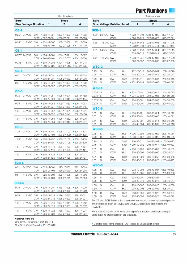
Part Numbers
Warner Electric 800-825-6544 35
Bore Stops
Size Voltage Rotation 1 2 4
CB-2
0.25" 24 VDC CW • 302-17-001 • 302-17-002 • 302-17-003
CCW • 302-27-001 • 302-27-011 302-27-003
0.25" 115 VAC CW • 302-17-007 302-17-008 302-17-009
CCW 302-27-007 302-27-008 • 302-27-009
CB-4
0.375" 24 VDC CW • 304-17-001 304-17-011 304-17-007
CCW • 304-27-001 304-27-007 • 304-27-026
0.375" 115 VAC CW • 304-17-003 • 304-17-008 304-17-018
CCW • 304-27-003 304-27-015 • 304-27-025
CB-5
0.5" 24 VDC CW • 305-17-001 • 305-17-002 305-17-003
CCW • 305-27-001 • 305-27-002 305-27-003
0.5" 115 VAC CW • 305-17-007 • 305-17-008 • 305-17-009
CCW • 305-27-007 • 305-27-008 • 305-27-009
CB-6
0.75" 24 VDC CW • 306-17-051 • 306-17-074 306-17-162
CCW • 306-27-029 • 306-27-046 • 306-27-134
0.75" 115 VAC CW • 306-17-053 • 306-17-060 • 306-17-073
CCW • 306-27-031 • 306-27-039 • 306-27-045
1.0" 24 VDC CW • 306-17-057 • 306-17-061 • 306-17-031
CCW • 306-27-032 • 306-27-147 306-27-150
1.0" 115 VAC CW • 306-17-059 • 306-17-062 306-17-075
CCW • 306-27-034 • 306-27-044 • 306-27-037
CB-8
1.25" 24 VDC CW • 308-17-101 • 308-17-102 • 308-17-103
CCW • 308-27-101 308-27-102 • 308-27-103
1.25" 115 VAC CW • 308-17-107 • 308-17-108 • 308-17-109CCW • 308-27-107 • 308-27-108 • 308-27-109
1.5" 24 VDC CW • 308-17-119 308-17-120 308-17-121
CCW • 308-27-119 308-27-120 308-27-121
1.5" 115 VAC CW • 308-17-125 • 308-17-126 308-17-127
CCW • 308-27-125 • 308-27-126 308-27-127
SCB-5
0.5" 24 VDC CW • 325-17-001 325-17-002 325-17-003
CCW 325-27-001 325-27-002 325-27-003
0.5" 115 VAC CW 325-17-004 325-17-005 325-17-006
CCW • 325-27-004 325-27-005 325-27-006
SCB-6
0.75" 24 VDC CW • 326-17-007 • 326-17-008 • 326-17-009
CCW • 326-27-007 • 326-27-008 326-27-009
0.75" 115 VAC CW • 326-17-019 • 326-17-020 326-17-021
CCW • 326-27-019 • 326-27-020 326-27-021
1.0" 24 VDC CW • 326-17-010 • 326-17-011 • 326-17-012
CCW • 326-27-010 • 326-27-011 326-27-012
1.0" 115 VAC CW • 326-17-022 326-17-023 326-17-024
CCW • 326-27-022 326-27-023 326-27-024
Bore Stops
Size Voltage Rotation Input 1 2 4
SCB-8
1.25" 24 VDC CW • 328-17-019 •328-17-020 328-17-021
CCW • 328-27-019 328-27-020 328-27-021
1.25" 115 VAC CW • 328-17-043 328-17-044 328-17-045
CCW • 328-27-043 • 328-27-044 • 328-27-0451.5" 24 VDC CW • 328-17-013 328-17-014 328-17-015
CCW 328-27-013 328-27-014 328-27-015
1.5" 115 VAC CW • 328-17-037 • 328-17-038 328-17-039
CCW 328-27-037 328-27-038 328-27-039
WSC-2
0.25" S CW Hub 202-10-016 202-10-009 202-10-020
0.25" S CCW Hub 202-20-016 202-20-015 202-20-017
0.25" S CW Shaft 202-30-011 202-30-007 202-30-015
0.25" S CCW Shaft • 202-40-014 202-40-008 202-40-017
WSC-4
0.375" S CW Hub • 204-10-001 204-10-016 204-10-0100.375" S CCW Hub • 204-20-004 204-20-008 204-20-016
0.375" S CW Shaft 204-30-001 204-30-007 204-30-009
0.375" S CCW Shaft 204-40-001 204-40-006 204-40-012
WSC-5
0.5" S CW Hub • 205-10-001 205-10-014 205-10-017
0.5" S CCW Hub • 205-20-001 205-20-006 205-20-011
0.5" S CW Shaft 205-30-001 205-30-014 205-30-016
0.5" S CCW Shaft 205-40-004 205-40-007 205-40-016
WSC-6
0.75" S CW Hub • 206-10-002 206-10-062 206-10-064
0.75" S CCW Hub • 206-20-002 206-20-023 206-20-058
0.75" S CW Shaft 206-30-011 206-30-052 • 206-30-025
0.75" S CCW Shaft • 206-40-002 206-40-014 • 206-40-020
1.0" S CW Hub • 206-10-003 206-10-057 206-10-059
1.0" S CCW Hub 206-20-003 206-20-060 206-20-013
1.0" S CW Shaft 206-30-003 206-30-051 206-30-056
1.0" S CCW Shaft 206-40-013 206-40-023 • 206-40-025
WSC-8
1.25" S CW Hub 208-10-004 208-10-027 • 208-10-028
1.25" S CCW Hub 208-20-001 208-20-028 208-20-030
1.25" S CW Shaft 208-30-001 208-30-021 —
1.25" S CCW Shaft 208-40-013 208-40-015 208-40-017
1.50" S CW Hub 208-10-007 208-10-025 208-10-0301.50" S CCW Hub 208-20-003 208-20-032 208-20-021
1.50" S CW Shaft 208-30-003 208-30-025 208-30-027
1.50" S CCW Shaft 208-40-003 208-40-020 208-40-022
For CB and SCB Series units, these are the most commonly requested parts –
other voltages (such as 12VDC and 90VDC), bores and stop collars are
available.
For the WSC Series, other units offering different bores, and overrunning or
start/coast-to-stop operation are available.
• Denotes stock items shipped FOB Roscoe or South Beloit, Illinois
Part Numbers Part Numbers
Control Part #’s
One Shot, 150 Ohms • 901-00-014
One Shot, Octal Socket • 901-00-019
7/21/2019 EMBRAGUE FRENO RESORTES
http://slidepdf.com/reader/full/embrague-freno-resortes 38/40
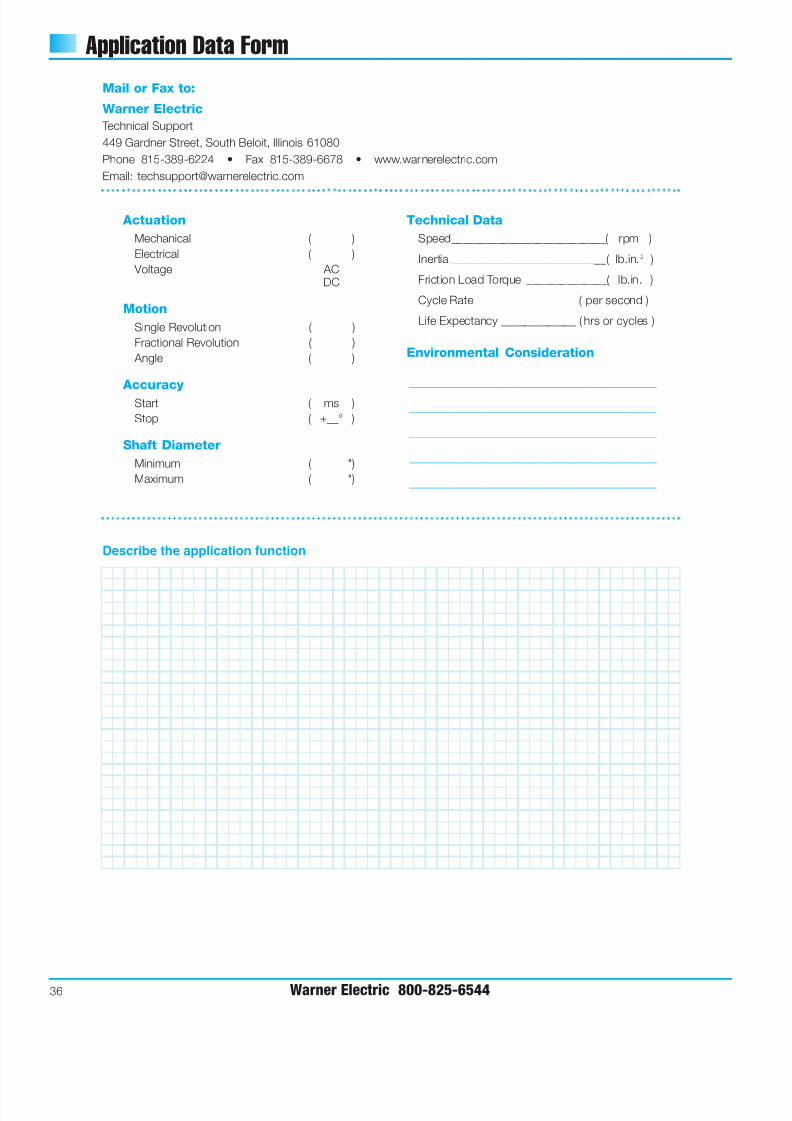
Application Data Form
36 Warner Electric 800-825-6544
Mail or Fax to:
Warner Electric
Technical Support
449 Gardner Street, South Beloit, Illinois 61080
Phone 815-389-6224 • Fax 815-389-6678 • www.warnerelectric.com
Email: [email protected]
Actuation
Mechanical ( )
Electrical ( )
Voltage ACDC
Motion
Single Revolution ( )
Fractional Revolution ( )
Angle ( )
Accuracy
Start ( ms )
Stop ( ±__° )
Shaft Diameter
Minimum ( ")
Maximum ( ")
Technical Data
Speed___________________________( rpm )
Inertia ___________________________( lb.in.2 )
Friction Load Torque ______________( lb.in. )
Cycle Rate _________________ ( per second )
Life Expectancy _____________ ( hrs or cycles )
Environmental Consideration
______________________________________
______________________________________
______________________________________
______________________________________
______________________________________
Describe the application function
7/21/2019 EMBRAGUE FRENO RESORTES
http://slidepdf.com/reader/full/embrague-freno-resortes 39/40
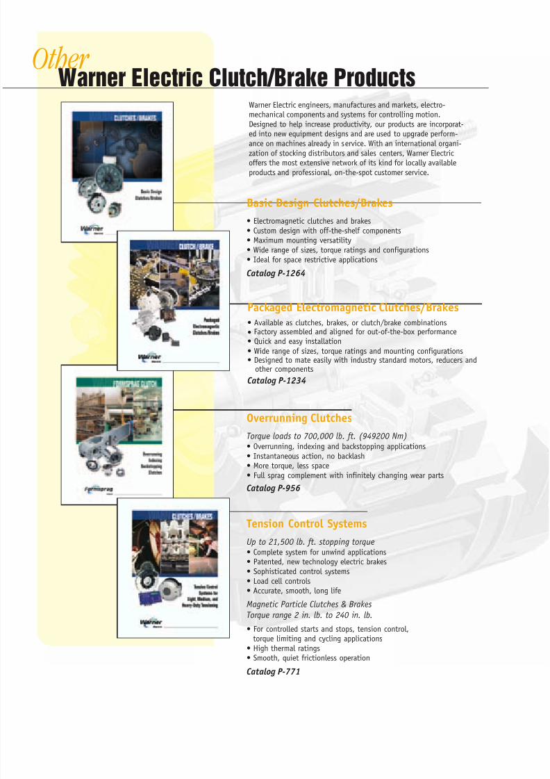
OtherWarner Electric Clutch/Brake Products
Basic Design Clutches/Brakes
• Electromagnetic clutches and brakes
• Custom design with off-the-shelf components
• Maximum mounting versatility
• Wide range of sizes, torque ratings and configurations
• Ideal for space restrictive applications
Catalog P-1264
Tension Control Systems
Up to 21,500 lb. ft. stopping torque• Complete system for unwind applications
• Patented, new technology electric brakes
• Sophisticated control systems
• Load cell controls
• Accurate, smooth, long life
Magnetic Particle Clutches & Brakes
Torque range 2 in. lb. to 240 in. lb.
• For controlled starts and stops, tension control,
torque limiting and cycling applications
• High thermal ratings
• Smooth, quiet frictionless operation
Catalog P-771
Overrunning Clutches
Torque loads to 700,000 lb. ft. (949200 Nm)• Overrunning, indexing and backstopping applications
• Instantaneous action, no backlash
• More torque, less space
• Full sprag complement with infinitely changing wear parts
Catalog P-956
Warner Electric engineers, manufactures and markets, electro-
mechanical components and systems for controlling motion.
Designed to help increase productivity, our products are incorporat-
ed into new equipment designs and are used to upgrade perform-ance on machines already in service. With an international organi-
zation of stocking distributors and sales centers, Warner Electric
offers the most extensive network of its kind for locally available
products and professional, on-the-spot customer service.
Packaged Electromagnetic Clutches/Brakes
• Available as clutches, brakes, or clutch/brake combinations
• Factory assembled and aligned for out-of-the-box performance
• Quick and easy installation
• Wide range of sizes, torque ratings and mounting configurations• Designed to mate easily with industry standard motors, reducers and
other components
Catalog P-1234
7/21/2019 EMBRAGUE FRENO RESORTES
http://slidepdf.com/reader/full/embrague-freno-resortes 40/40