"The Evolution of Object Recognition in Embedded Systems," a Presentation from CEVA
Upload
surender-chauhanCategory
view
49download
1
EMBEDDED SYSTEMS
1
Study Of flow Of Electrons
Nothing Without Current
Basically A Branch Of Science Which Have No Limits
Full Of Creativity.
Transforming Ideas Into Reality
Only Limit Is Imagination
Embedded Systems Are Heart Of Electronics
2
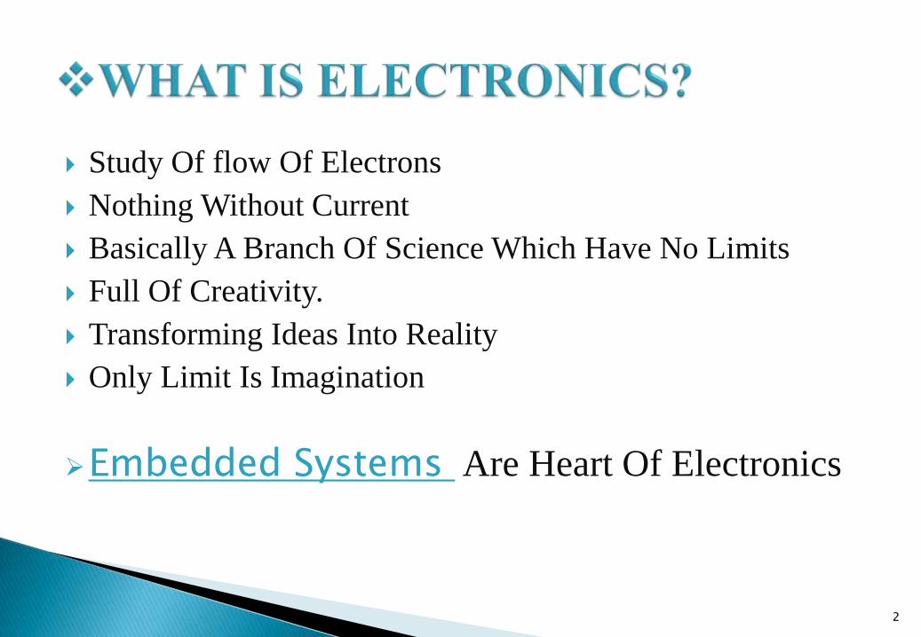
Also Known As Potential Difference
Because Represents The Potential Gap Between Two Points
Always Measured With A Reference Point
Root Cause Of Flow Of Current
Determines Total Electromotive Force Acting Between Charges
Basically The Amount Of Charge Determines The Potential Of A
Point
3
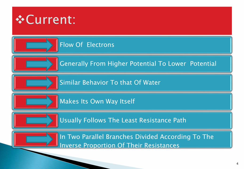
Flow Of Electrons
Generally From Higher Potential To Lower Potential
Similar Behavior To that Of Water
Makes Its Own Way Itself
Usually Follows The Least Resistance Path
In Two Parallel Branches Divided According To The
Inverse Proportion Of Their Resistances
4
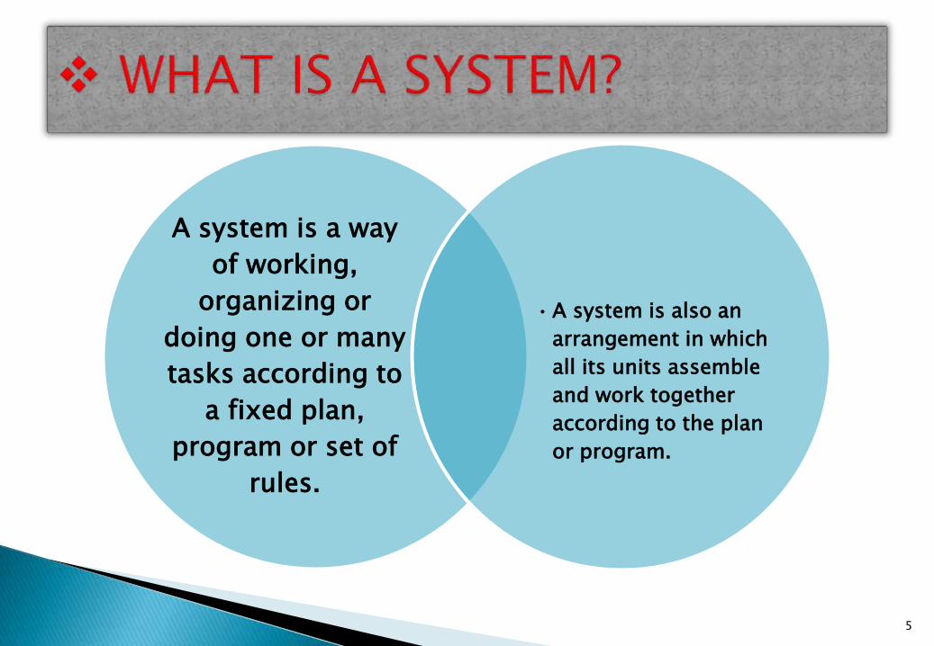
A system is a way
of working,
organizing or
doing one or many
tasks according to
a fixed plan,
program or set of
rules.
• A system is also an
arrangement in which
all its units assemble
and work together
according to the plan
or program.
5
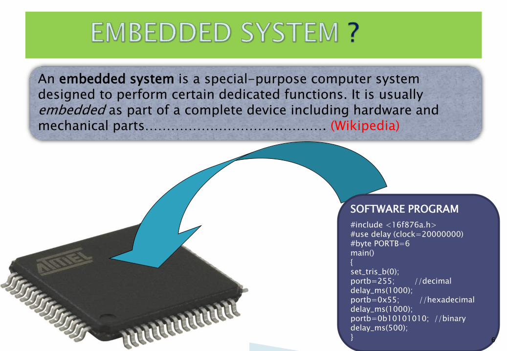
SOFTWARE PROGRAM
#include <16f876a.h>#use delay (clock=20000000)#byte PORTB=6main(){set_tris_b(0);portb=255; //decimaldelay_ms(1000);portb=0x55; //hexadecimaldelay_ms(1000);portb=0b10101010; //binarydelay_ms(500);}
An embedded system is a special-purpose computer system designed to perform certain dedicated functions. It is usually embedded as part of a complete device including hardware and mechanical parts…………………………..………. (Wikipedia)
6
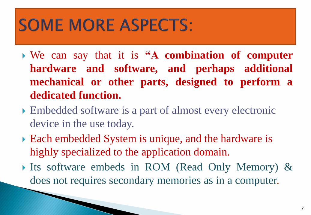
We can say that it is “A combination of computer
hardware and software, and perhaps additional
mechanical or other parts, designed to perform a
dedicated function.
Embedded software is a part of almost every electronic
device in the use today.
Each embedded System is unique, and the hardware is
highly specialized to the application domain.
Its software embeds in ROM (Read Only Memory) &
does not requires secondary memories as in a computer.
7
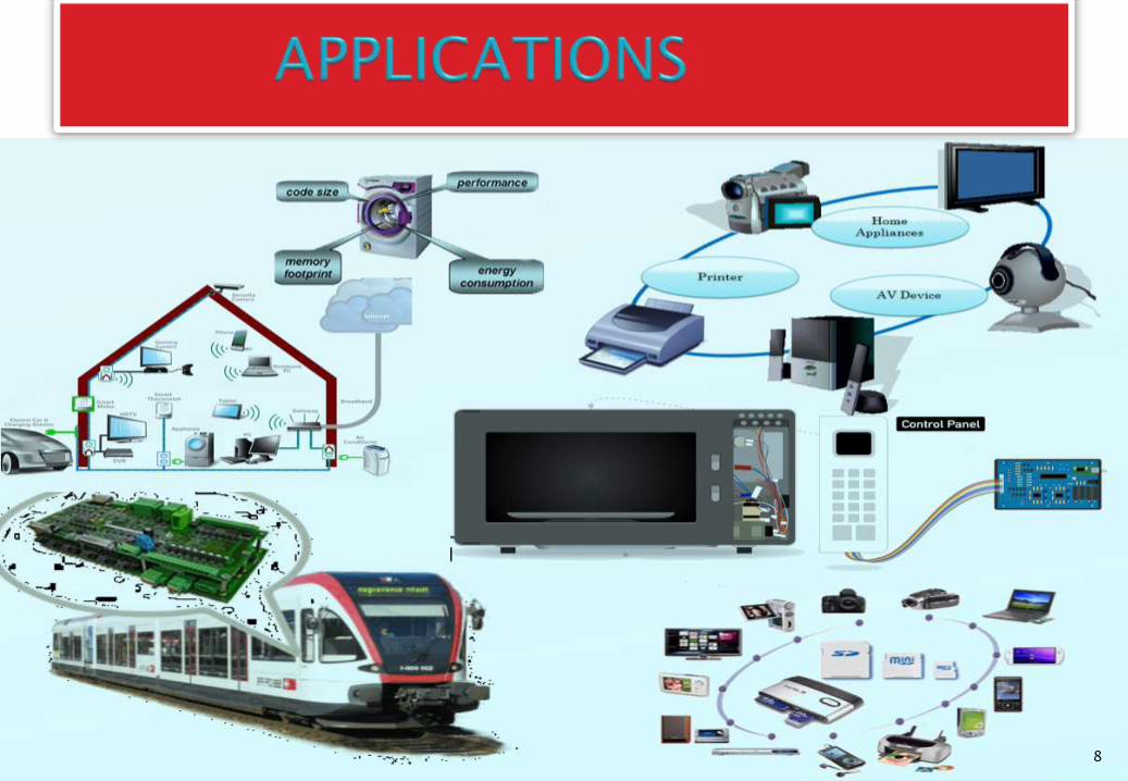
8
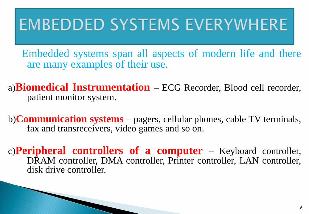
Embedded systems span all aspects of modern life and thereare many examples of their use.
a)Biomedical Instrumentation – ECG Recorder, Blood cell recorder,patient monitor system.
b)Communication systems – pagers, cellular phones, cable TV terminals,fax and transreceivers, video games and so on.
c)Peripheral controllers of a computer – Keyboard controller,DRAM controller, DMA controller, Printer controller, LAN controller,disk drive controller.
9
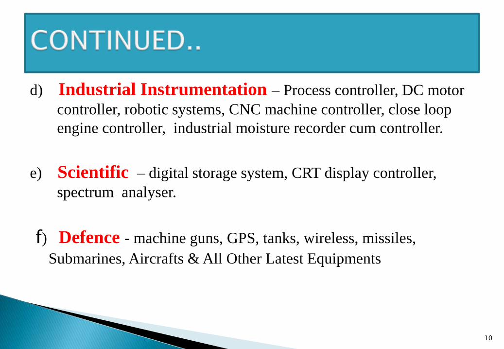
d) Industrial Instrumentation – Process controller, DC motor
controller, robotic systems, CNC machine controller, close loop
engine controller, industrial moisture recorder cum controller.
e) Scientific – digital storage system, CRT display controller,
spectrum analyser.
f) Defence - machine guns, GPS, tanks, wireless, missiles,
Submarines, Aircrafts & All Other Latest Equipments
10
11
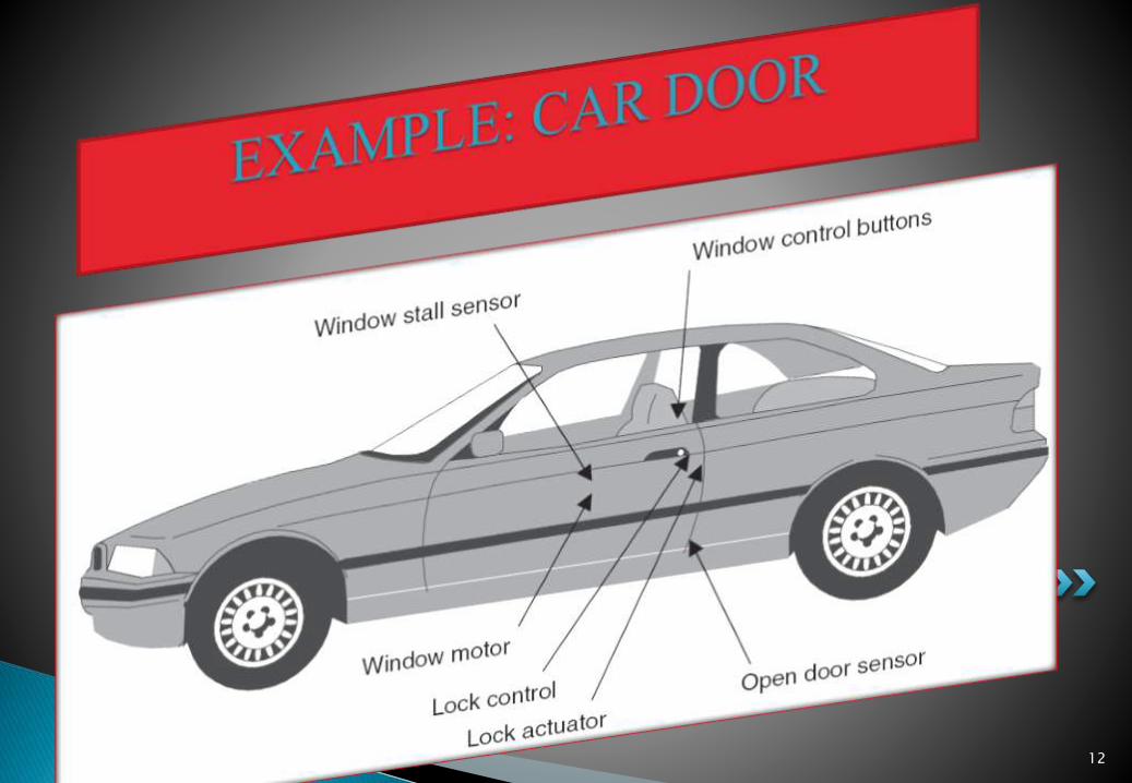
12
Every embedded system consists of custom-built hardwarebuilt around a Central Processing Unit (CPU). Thishardware also contains memory chips onto which thesoftware is loaded. The software residing on the memorychip is also called the ‘firmware’.
The operating system runs above the hardware, andthe application software runs above the operatingsystem. The same architecture is applicable to anycomputer including a desktop computer.However,there are some significant differences. Itis not compulsory to have an operating system inevery embedded system.
13
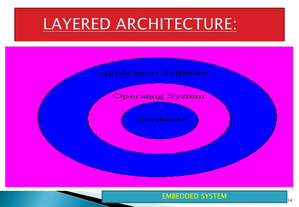
EMBEDDED SYSTEM14
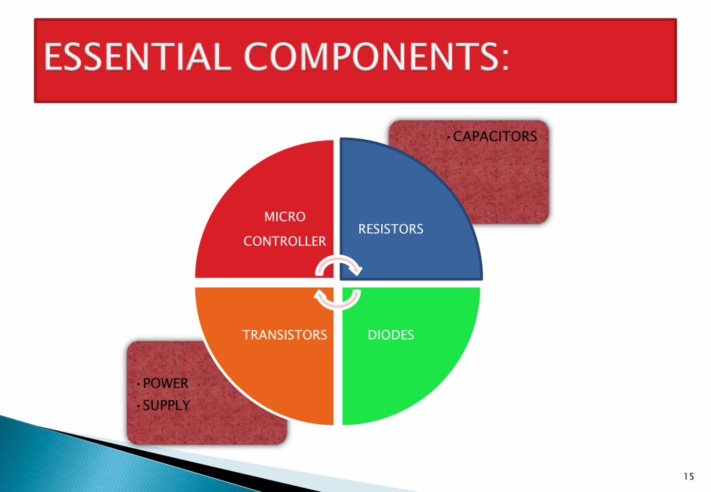
•POWER
•SUPPLY
•CAPACITORS
MICRO
CONTROLLERRESISTORS
DIODESTRANSISTORS
15
16
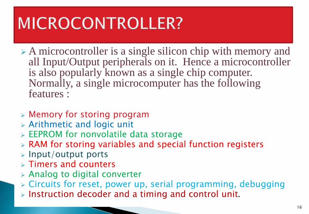
A microcontroller is a single silicon chip with memory and all Input/Output peripherals on it. Hence a microcontroller is also popularly known as a single chip computer. Normally, a single microcomputer has the following features :
Memory for storing program Arithmetic and logic unit EEPROM for nonvolatile data storage RAM for storing variables and special function registers Input/output ports Timers and counters Analog to digital converter Circuits for reset, power up, serial programming, debugging Instruction decoder and a timing and control unit.
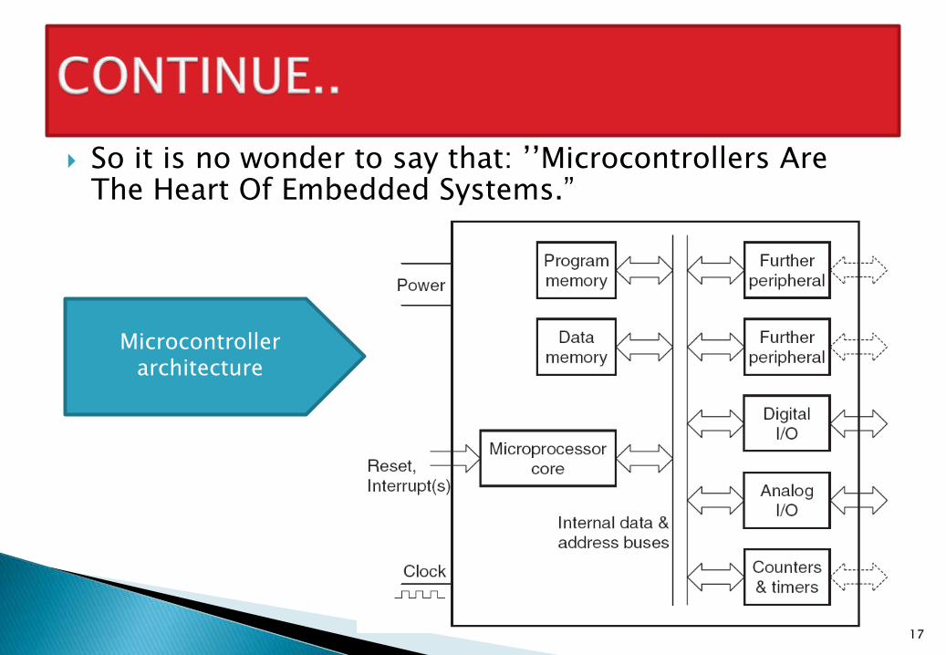
So it is no wonder to say that: ’’Microcontrollers Are The Heart Of Embedded Systems.”
17
Microcontroller architecture
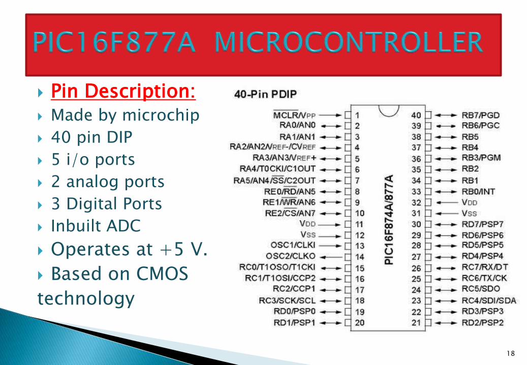
Pin Description: Made by microchip
40 pin DIP
5 i/o ports
2 analog ports
3 Digital Ports
Inbuilt ADC
Operates at +5 V.
Based on CMOS
technology
18
Use of microcontroller always involves someinterfacing.
Interfacing is nothing but connecting an i/o device orsome other device with our microcontroller.
Basically it is the effective interfacing whichcompletes the embedded system
Various components like LCD, Switch, Led, Relayetc. will have to be interface with the microcontroller.
In the next few slides we will explain theseinterfacings.
19
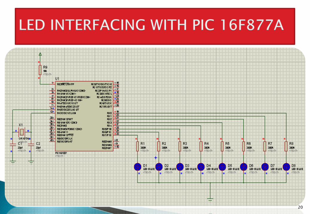
20
21
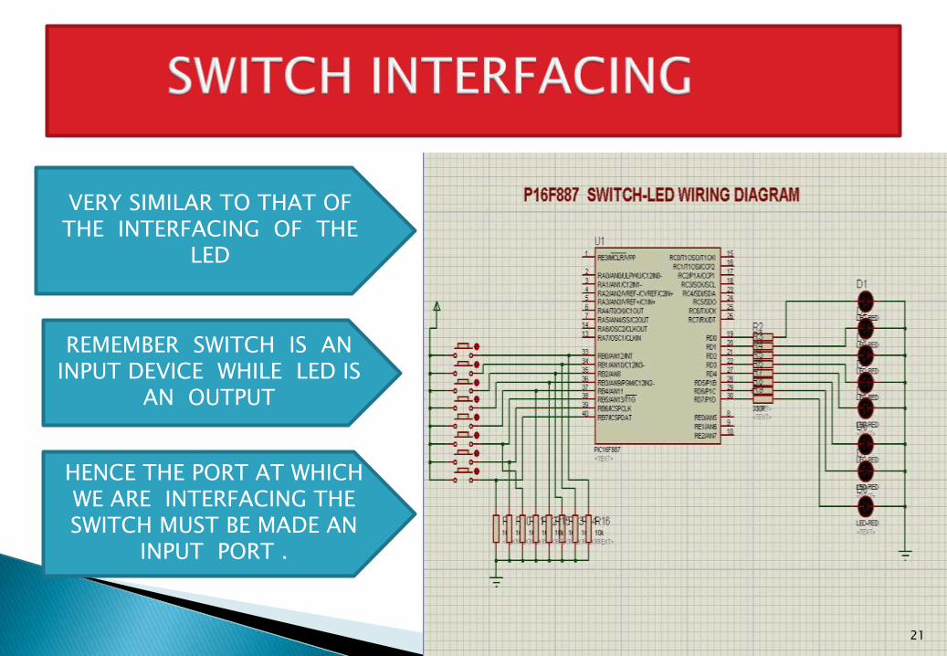
VERY SIMILAR TO THAT OF THE INTERFACING OF THE
LED
REMEMBER SWITCH IS AN INPUT DEVICE WHILE LED IS
AN OUTPUT
HENCE THE PORT AT WHICH WE ARE INTERFACING THE SWITCH MUST BE MADE AN
INPUT PORT .
If we want to make port B as input Port & Port C as output Port. Then write:
TRISB=0XFF
TRISC=0X00
All this programming for PIC16F877A is done in embedded C by using “MPLAB” software.
The MPLAB is designed and developed by ‘microchip’.
22
23
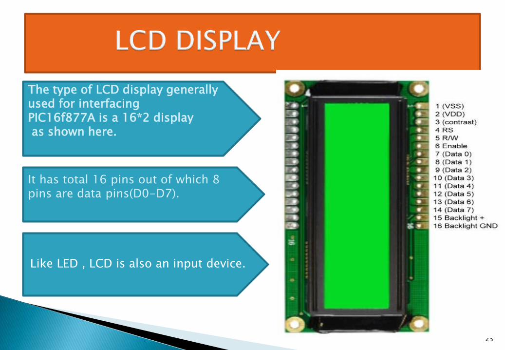
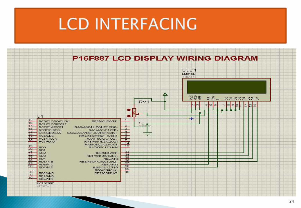
The type of LCD display generally used for interfacingPIC16f877A is a 16*2 display as shown here.
It has total 16 pins out of which 8 pins are data pins(D0-D7).
Like LED , LCD is also an input device.
24
25
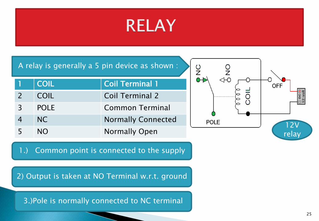
A relay is generally a 5 pin device as shown :
1 COIL Coil Terminal 1
2 COIL Coil Terminal 2
3 POLE Common Terminal
4 NC Normally Connected
5 NO Normally Open
1.) Common point is connected to the supply
12V relay
2) Output is taken at NO Terminal w.r.t. ground
3.)Pole is normally connected to NC terminal
26
27
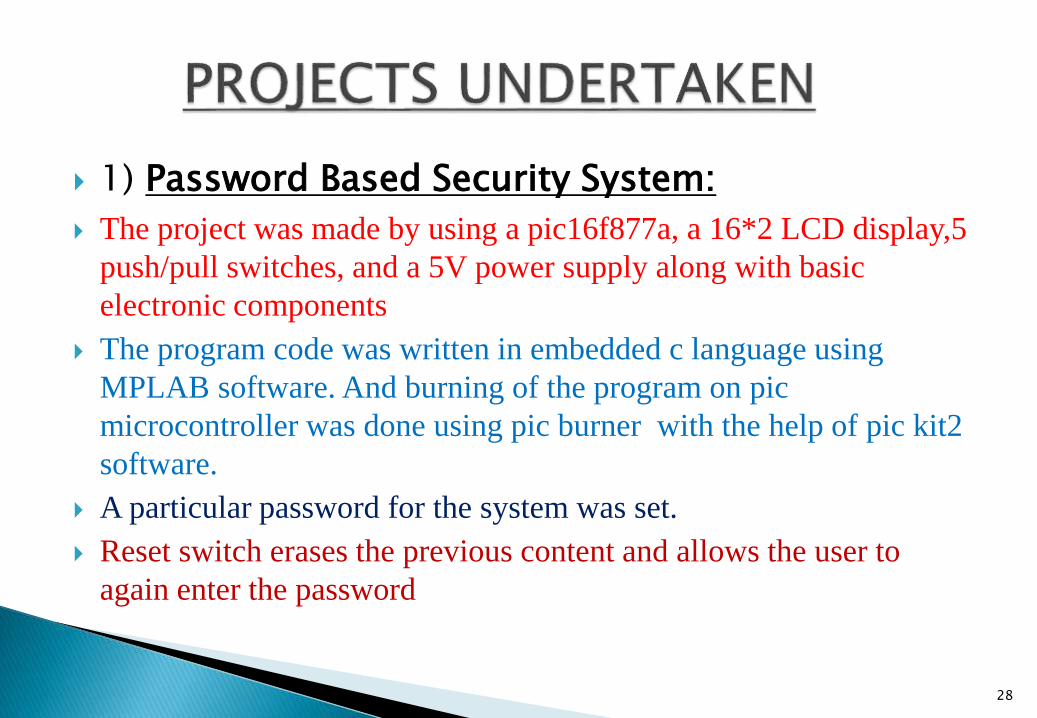
1) Password Based Security System:
The project was made by using a pic16f877a, a 16*2 LCD display,5
push/pull switches, and a 5V power supply along with basic
electronic components
The program code was written in embedded c language using
MPLAB software. And burning of the program on pic
microcontroller was done using pic burner with the help of pic kit2
software.
A particular password for the system was set.
Reset switch erases the previous content and allows the user to
again enter the password
28
If the password enter by the user is correct then the LCD display shows the message ‘password matched.’
However if the password entered is incorrect thenthe LCD display shows the massage ‘Unauthorised User’.
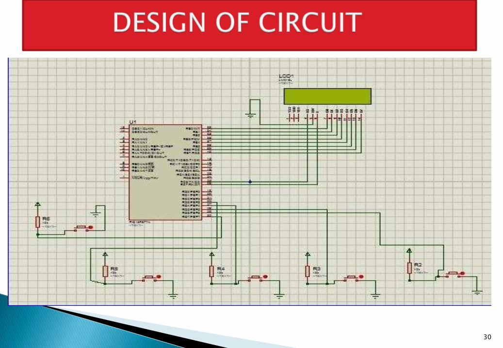
Next slide shows the design of this circuit in Proteus software.
29
30
31
Consist of an RF transmitter/reciever module (BX- R433a)
Transmitter contains IC HT-12E as encoder.
Reciever contains IC HT-12D as decoder.
The driving section contains a dc motor having atleast 1000
rpm
The motor is driven by the motor driver IC L293D
By getting commands from the reciever output.
Switches are provided on transmitter section to control the motor.
32
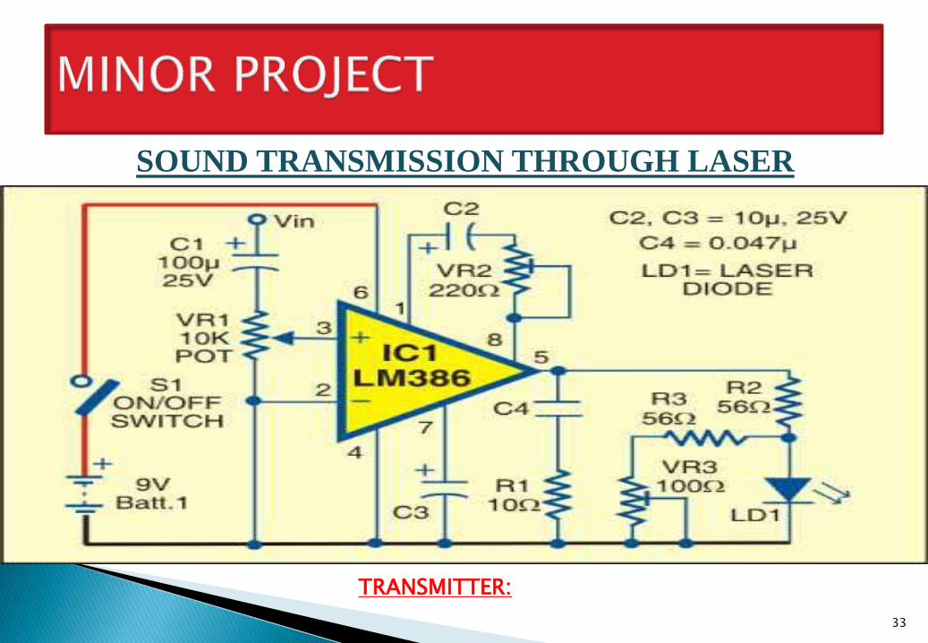
SOUND TRANSMISSION THROUGH LASER
33
TRANSMITTER:
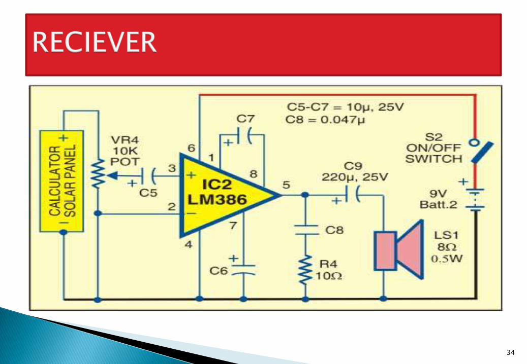
34

35