Embedded Systems - Duke Universitypeople.duke.edu/~tkb13/courses/ncsu-csc230/lecture... ·...
140
Embedded Systems C Programming and Software Tools N.C. State Department of Computer Science Adapted from “EE498/ EE578 Real-Time Embedded Systems” by Nannan He, Minnesato State University at Mankato (2014) http://mavweb.mnsu.edu/hen/lec/RTES_fundamental.pptx
Transcript of Embedded Systems - Duke Universitypeople.duke.edu/~tkb13/courses/ncsu-csc230/lecture... ·...

Embedded Systems C Programming and Software Tools N.C. State Department of Computer Science
Adapted from “EE498/ EE578 Real-Time Embedded Systems” by
Nannan He, Minnesato State University at Mankato (2014)
http://mavweb.mnsu.edu/hen/lec/RTES_fundamental.pptx

Definition: System
A system is a mapping of a set of inputs into a set of outputs.
2
System
Mapping Function... ..
.
Inputs Outputs
Input Space Output Space
1. A system is an assembly of components connected together in an organized way
2. A system is fundamentally altered if a component joins or leaves it 3. It has a purpose 4. It has a degree of permanence 5. It has been defined as being of particular interest

Example: A Real-Time Control
System
• Inputs are excitations and outputs are corresponding responses
• Inputs and outputs may be digital or analog
• Inputs are associated with sensors, cameras, etc.
• Outputs with actuators, displays, etc.
3
Real-Time Control System
..
. ...
Camera Display
Sensors Actuators

Definition: Response Time
The time between the presentation of a set of inputs to a system and the realization of the required behavior, including the availability of all associated outputs, is
called the response time of the system
• How fast and punctual does it need to be?
– Depends on the specific real-time system
• But what is a real-time system?
4

Definitions: Real-Time System
A real-time system is a computer system that must satisfy bounded response-time constraints or risk severe
consequences, including failure
A real-time system is one whose logical correctness is based on both the correctness of the outputs and their timeliness
5

Definition: Failed System
A failed system is a system that cannot satisfy one or more of the requirements stipulated in the system
requirements specification
• Hence, rigorous specification of the system
operating criteria, including timing constraints,
is necessary
6

Definition: Embedded System
An embedded system is a system containing one or more computers (or processors) having a central role in
the functionality of the system, but the system is not explicitly called a computer
• A real-time system may be embedded or non-embedded
• But it is always reactive – Task scheduling is driven by ongoing interaction with
the environment
7

Degrees of “Real-Time”
• All practical systems are ultimately real-time systems
• Even a batch-oriented system—for example, grade processing at the end of a semester—is real-time
• Although the system may have response times of days, it must respond within a certain time
• Even a word-processing program should respond to commands within a reasonable amount of time
• Most of the literature refers to such systems as soft real-time systems
8

Soft, Hard, and Firm “Real-Time”
Definition: Soft Real-Time System A soft real-time system is one in which performance is degraded but not destroyed by failure to meet response-time constraints
Definition: Hard Real-Time System A hard real-time system is one in which failure to meet even a single deadline may lead to complete or catastrophic system failure
Definition: Firm Real-Time System A firm real-time system is one in which a few missed deadlines will not lead to total failure, but missing more than a few may lead to complete or catastrophic system failure
9

Example: Real-Time Classification
System Real-Time Classification
Explanation
Avionics weapons delivery system in which pressing a button launches an air-to-air missile
Hard Missing the deadline to launch the missile within a specified time after pressing the button may cause the target to be missed, which will result in a catastrophe
Navigation controller for an autonomous weed-killer robot
Firm Missing a few navigation deadlines causes the robot to veer out from a planned path and damage some crops
Console hockey game Soft Missing even several deadlines will only degrade performance
10

Where Do Deadlines Come from?
• Deadlines are based on the underlying
physical phenomena of the system under
control
11

Example: Where a Response Time
Comes from?
• An elevator door is automatically operated and it may have a sensor to detect passengers between the closing doors so it can re-open automatically.
• What is the required system response time from when it recognizes that a passenger is between the closing door blades and starting to reopen the door?
12
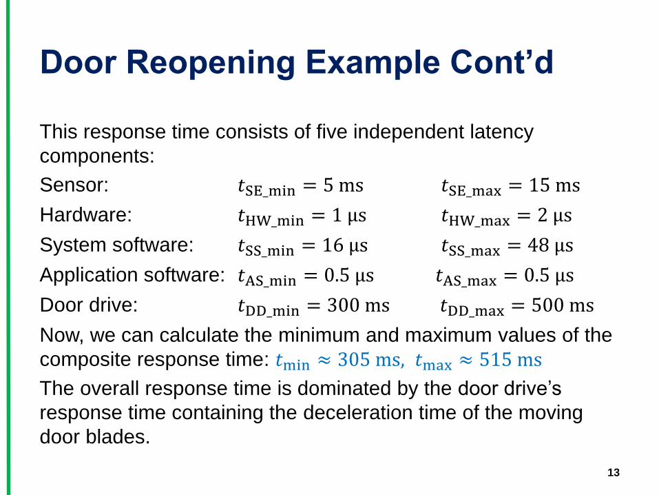
Door Reopening Example Cont’d
This response time consists of five independent latency
components:
Sensor: 𝑡SE_min = 5 ms 𝑡SE_max = 15 ms
Hardware: 𝑡HW_min = 1 μs 𝑡HW_max = 2 μs
System software: 𝑡SS_min = 16 μs 𝑡SS_max = 48 μs
Application software: 𝑡AS_min = 0.5 μs 𝑡AS_max = 0.5 μs
Door drive: 𝑡DD_min = 300 ms 𝑡DD_max = 500 ms
Now, we can calculate the minimum and maximum values of the
composite response time: 𝑡min ≈ 305 ms, 𝑡max ≈ 515 ms
The overall response time is dominated by the door drive’s
response time containing the deceleration time of the moving
door blades.
13

Definitions: Event and Release
Time
Definition: Event
Any occurrence that causes the program counter to change non-sequentially is considered a change of flow-of-control, and thus an event
Definition: Release Time
The release time is the time at which an instance of a scheduled task is ready to run, and is generally associated with an interrupt
14

Taxonomy of Events
• Synchronous or asynchronous? – Synchronous events: occur at predictable times in
the flow-of-control
– Asynchronous events: occur at unpredictable times, are usually caused by external sources
• Periodic, aperiodic or sporadic? – Periodic: A real-time clock that pulses regularly
– Aperiodic: Events that do not occur at regular periods
– Sporadic: Aperiodic events that tend to occur very infrequently
15

Example: Various Types of Events
Type Periodic Aperiodic Sporadic
Synchronous Cyclic code
Conditional branch Divide-by-zero (trap) interrupt
Asynchronous Clock interrupt
Regular, but not fixed-period interrupt
Power-loss alarm
16

CPU Utilization or Time-Loading
Factor
• The measure of the relative time spent doing
non-idle processing indicates how much real-
time processing is occurring
Definition: CPU Utilization Factor
The CPU utilization or time-loading factor, U, is a relative measure of the non-idle processing taking place
17

Example: Calculation of U
Suppose, an individual elevator controller in a bank of elevators has the following tasks with execution periods of 𝑝𝑖 and worst-case execution times of 𝑒𝑖, 𝑖 ∈ 1,2,3,4 :
Task 1: Communicate with the group dispatcher.
Task 2: Update the car position information and manage floor-to-floor runs as well as door control.
Task 3: Register and cancel car calls.
Task 4: Miscellaneous system supervisions.
18
i 𝒆𝒊 𝒑𝒊
1 17 ms 500 ms
2 4 ms 25 ms
3 1 ms 75 ms
4 20 ms 200 ms
𝑈 = 𝑒𝑖 𝑝𝑖 4𝑖=1 =0.31
31% (Very safe zone)

Goal: get to a reasonable U
• U too high? Possible chance of failure
• U too low? Not cost effective
• U = 50% for new systems,
• U = 80% for stable, well-known systems
19

Cost/performance tradeoff Model Cost Clock CPU type Flash RAM I/O lines
ATTINY4 $0.40 12 MHz 8-bit AVR 512 B 32 B 4
ATTINY44 $0.75 20 MHz 8-bit AVR 4 kB 256 B 12
ATMEGA48 $1.23 20 MHz 8-bit AVR 4 kB 512 B 23
ATMEGA328 $1.68 20 MHz 8-bit AVR 32 kB 2 kB 23
ATXMEGA128 $2.72 32 MHz 16-bit AVR 128 kB 8 kB 50
AT32UCA1256 $8.59 66 MHz 32-bit AVR 256 kB 64 kB 69
NXP LPC4370FET256E
$11.98 204 MHz 32-bit 3-core ARM
1 MB 136 kB 83
Intel Core i7 4790K (comedy option)
$339.99 4 GHz 64-bit quad-core x86
None onboard
None onboard (max ~64GB attached)
500+ (but none are general-purpose)
20

Usual Misconception
“Real-time” means “fast”?
NO!!!
“Real-time” means “predictable timing”
21

Practical Embedded Systems
• Aerospace – Flight control
– Navigation
– Pilot interface
• Automotive – Airbag deployment
– Antilock braking
– Fuel injection
• Household – Microwave oven
– Rice cooker
– Washing machine
• Industrial – Crane
– Paper machine
– Welding robot
• Multimedia – Console game
– Home theater
– Simulator
• Medical – Intensive care monitor
– Magnetic resonance imaging
– Remote surgery
22

Inertial measurement system for an
aircraft
Inertial
measurement
system
accelerometers from x, y, z
temperature sensor
10ms
1s
acceleration, velocity,
and position vectors
40ms
The tasks execute at different rates and need to communicate and synchronize.

Monitoring system for a nuclear power
plant
monitoring
system
security breach indicator 1ms
event2 over-temperature indicator
event1 Display
updating
33.3ms
Ensure that the “meltdown imminent” indicator can interrupt any other processing with minimal latency.

ARDUINO STUFF
This presentation is based on an electronics seminar I put on as part of the TerrorBytes robotics team. It includes material from:
• Farzad Towhidkhah. Amirkabir University of Technology. Electrical Circuits, lecture 1. http://bme2.aut.ac.ir/~towhidkhah/Circuit/Circuit1/PPT/lec1.ppt
• Jefferson Lab. Electrical Circuits. http://education.jlab.org/jsat/powerpoint/0708_electricity.ppt
• Worldofteaching.com. Electric Circuits. http://www.worldofteaching.com/powerpoints/physics/electric%20circuits.ppt
• Sparkfun. Introduction to Electronics and Breadboarding Circuits. http://create.coloradovirtuallibrary.org/sites/default/files/Curriculum/SparkFun/Beginner/IntrotoBasicElectronics.ppt
• Sparkfun. Intro to Arduino. http://create.coloradovirtuallibrary.org/sites/default/files/Curriculum/SparkFun/Beginner/IntrotoArduino.ppt
25

Arduino Board
• “Strong Friend” Created in Ivrea, Italy
• in 2005 by Massimo Banzi & David Cuartielles
• Open Source Hardware
• Processor
• Coding is accessible & transferrable (C++, Processing, java)

Your kit
9V battery
Some kind of Arduino
10kΩ
Resistor
1kΩ
Resistor
or or
You can get all this stuff dirt cheap on ebay

How to hook stuff together easily

Analog
INPUTS
Digital I\O PWM(3, 5, 6, 9, 10, 11)
PWR IN USB
(to Computer)
SCL\SDA (I2C Bus)
POWER 5V / 3.3V / GND
RESET
Arduino Overview

digitalWrite()
analogWrite()
digitalRead()
if() statements / Boolean
analogRead()
Serial communication
BIG
6 C
ON
CEP
TS

Project – Digital Input
• In Arduino, open up:
• File Examples 02.Digital Button

Digital Sensors (a.k.a. Switches) Pull-up Resistor
to Digital Pin 2

Digital Sensors (a.k.a. Switches) Add an indicator LED to Pin 13
This is just like our 1st circuit!

Digital Input
• Connect digital input to your Arduino using Pins # 0 – 13 (Although pins # 0 & 1 are also used for programming)
• Digital Input needs a pinMode command: pinMode(pinNumber, INPUT);
Make sure to use ALL CAPS for INPUT
• To get a digital reading: int buttonState = digitalRead(pinNumber);
• Digital Input values are only HIGH (On) or LOW (Off)

Digital Sensors
• Digital sensors are more straight forward than Analog
• No matter what the sensor there are only two settings: On and Off
• Signal is always either HIGH (On) or LOW (Off)
• Voltage signal for HIGH will be a little less than 5V on your Uno
• Voltage signal for LOW will be 0V on most systems

Voltage dividers
• You get an in-between voltage based on the two resistances
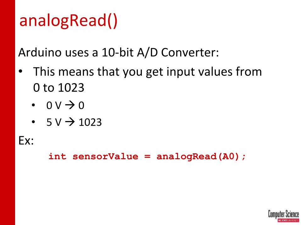
analogRead()
Arduino uses a 10-bit A/D Converter:
• This means that you get input values from 0 to 1023
• 0 V 0
• 5 V 1023
Ex: int sensorValue = analogRead(A0);

Using Serial Communication
Method used to transfer data between two devices.
Arduino dedicates Digital I/O pin # 0 to
receiving and Digital I/O pin #1 to
transmit.
Data passes between the computer and Arduino
through the USB cable. Data is transmitted as
zeros (‘0’) and ones (‘1’) sequentially.

Serial Monitor & analogRead()
Initializes the Serial
Communication
9600 baud data rate
prints data to serial bus

Serial Monitor & analogRead()
Opens up a Serial
Terminal Window

The following slides comprise the entirety of the electronics workshop I put on with the TerrorBytes robotics team. It’s aimed at a high school audience, so skip the basics as needed.
CSC230: C and Software Tools © NC State Computer Science Faculty 41

What can you do with this?
• We built an LED light sensor to act as a “middle limit switch” to find our shooting position.
• Run by an Arduino; acts like a normal limit switch to the cRIO

Process
Prototype Coding Quick-and-dirty build
Custom PCB

Your kit
9V battery
Some kind of Arduino
10kΩ Resistor 1kΩ Resistor
or or

Sources used in this presentation
• This presentation includes material from: – Farzad Towhidkhah. Amirkabir University of
Technology. Electrical Circuits, lecture 1. http://bme2.aut.ac.ir/~towhidkhah/Circuit/Circuit1/PPT/lec1.ppt
– Jefferson Lab. Electrical Circuits. http://education.jlab.org/jsat/powerpoint/0708_electricity.ppt
– Worldofteaching.com. Electric Circuits. http://www.worldofteaching.com/powerpoints/physics/electric%20circuits.ppt
– Sparkfun. Introduction to Electronics and Breadboarding Circuits. http://create.coloradovirtuallibrary.org/sites/default/files/Curriculum/SparkFun/Beginner/IntrotoBasicElectronics.ppt
– Sparkfun. Intro to Arduino. http://create.coloradovirtuallibrary.org/sites/default/files/Curriculum/SparkFun/Beginner/IntrotoArduino.ppt

PART 1: ELECTRICITY IS A THING!

Introduction to Electric Circuits
• Here we are going to remind what are: – Voltage
– Current
– Current flow
– Voltage Sources
– Voltmeter (Multimeter)
48

What is Voltage?
49
V = “Electrical pressure” - measured in volts.
H2O
High Pressure Low Pressure
Figure 1.1

The water analogy
• A battery in an electrical circuit plays the same role as a pump in a water system.
50

What produces voltage?
51
V = “Electrical pressure”
A Battery
Electric Power Plant
Lab Power Supply
Nerve Cell
1.5 V
9 V
13,500 V
A few
Volts
Solar Cell
A few millivolts when activated by a synapse

Symbols Used for Voltage Sources
52
+ _
+
_
Battery
+
_
Battery
All these symbols are interchangable.

What voltages are used in FRC?

What is “Ground”?
54
“Ground” refers to the reference terminal to
which all other voltages are measured
+ _ V1 +
_ V2 + _ V3
Point of Reference
In non-battery-powered things, ground is usually literally connected to a spike into the ground
Ground Symbol

Ground in robotics
• We call the negative of the battery “ground”

What is Current?
56
• Current is the flow of charge from a voltage source
• 1 Ampere (“Amp”) = Flow of 1 Coulomb/sec
+++

How Does Current Flow?
57
Current can only flow through conductors
+++
Metal wires (conductors)
Current
flow

When Does Current NOT Flow?
58
+++
Plastic material (insulators)
Current cannot flow through insulators
No current
flow

Note that Air is an Insulator
59
+++ Air
Current cannot flow through insulators
No current flow
That’s why a battery doesn’t
discharge if left on its own.

Current Flow Analogy
High Current Low Current

Water Tower
Voltage Analogy
More Energy == Higher Voltage Less Energy == Lower Voltage
V
Water Tower
V

Resistance Analogy
Big Pipe == Lower Resistance Small Pipe == Higher Resistance
Water Tower
Water Tower
V

Ohm’s Law
V = I R or
I = V / R
Georg Simon Ohm (1787-1854)
I = Current (Amperes) (amps, A) V = Voltage (Volts, V) R = Resistance (ohms, Ω)
Welp, here’s my entire life’s work boiled down to one
really easy equation. Oh well.
Describes the relationship between voltage, current, and resistance.

Electrical Properties
Voltage
V
• Defined as the amount of potential energy in a circuit.
• Units: Volts (V)
Current
I
• The rate of charge flow in a circuit.
• Units: Amperes (A)
Resistance
R
• Opposition to charge flow.
• Units: Ohms (Ω)

Resistance
• Anything that isn’t a PERFECT conductor has resistance (and nothing’s perfect).
• 20 ft. of 18AWG wire: 0.128 Ω
• 60W incandescent lightbulb: 240 Ω
• My face: ~30 MΩ

Resistors
• Resistors provide a specific amount of resistance to a path in a circuit or wire.
• Resistors are color coded. Circuit symbol for a resistor

battery switch lamp wires
Exercise

Exercise
120 Ω
12 V
What’s the CURRENT?

Get with it, grandma
• Lightbulbs are for old people
• Light Emitting Diodes (LEDs) are where it’s at!

What are LEDs?
• Light Emitting Diodes
• Diode Symbol + Arrows for light
• Points to ground
Can emit a variety of colors
Long leg is POSITIVE
Short leg is NEGATIVE

Rules of LEDs
• They need above a certain voltage to turn on (the forward voltage drop)
– Typically 1.5 – 3 V
• They need less than a certain current to not burn up
– Typically 5 – 20 mA (milli-amps)
This is your LED…
This is your LED on too much current. Any questions?

How to limit current?
• I have a 12V source
• I have an LED
• How can I limit the current?????
• I’m going to give it 12V • The LED will eat 2V • That leaves 10V left • What resistor will limit
the extra 10V to 10mA (0.01 A)?
• V = I * R • 10 = 0.01 * R • R = 10 / 0.01 • R = 1000 • 1000 Ohms!

How to hook stuff together easily

LET’S ACTUALLY DO A THING!!!
• Make that LED turn on!!

PART 2: ARDUINO DOES STUFF!

Add computing to your circuit
• All this electronics stuff is cool, but I want to DO STUFF, not make a light turn on
• Enter Arduino
– Tiny little computer that’s really cheap
– Designed to talk to electronics

Arduino Board
• “Strong Friend” Created in Ivrea, Italy
• in 2005 by Massimo Banzi & David Cuartielles
• Open Source Hardware
• Processor
• Coding is accessible & transferrable (C++, Processing, java)

Analog INPUTS
Digital I\O PWM(3, 5, 6, 9, 10, 11)
PWR IN USB (to Computer)
SCL\SDA (I2C Bus)
POWER 5V / 3.3V / GND
RESET
Arduino Overview

Go ahead and plug your board in!

Replace the 9V with the Arduino

Adding control
• Let’s use the Arduino and start programming!!!

Concepts: INPUT vs. OUTPUT
• Referenced from the perspective of the microcontroller (electrical board).
Inputs is a signal / information
going into the board.
Output is any signal exiting the
board.
Almost all systems that use physical computing will have some form of output What are some examples of Outputs?

Concepts: INPUT vs. OUTPUT
• Referenced from the perspective of the microcontroller (electrical board).
Inputs is a signal / information
going into the board.
Output is any signal exiting the
board.
Examples: Buttons Switches, Light Sensors, Flex Sensors, Humidity Sensors, Temperature Sensors…
Examples: LEDs, DC motor, servo motor, a piezo buzzer, relay, an RGB LED

Concepts: Analog vs. Digital
• Microcontrollers are digital devices – ON or OFF. Also called – discrete.
• analog signals are anything that can be a full range of values. What are some examples? More on this later…
5 V
0 V
5 V
0 V

Open up Arduino
• Hints:
• For PC Users
• Run the installer copy and move the files to the appropriate locations, or
• For Mac Users
1. Move the Arduino executable to the dock for ease of access.
2. Resist the temptation to run these from your desktop.

Arduino Integrated Development Environment (IDE)
Two required functions / methods / routines:
void setup() {
// runs once
}
void loop() {
// repeats
}
error & status messages

Settings: Tools Serial Port
• Your computer communicates to the Arduino microcontroller via a serial port through a USB-Serial adapter.
• Check to make sure that the drivers are properly installed.

Settings: Tools Board
• Next, double-check that the proper board is selected under the ToolsBoard menu.

digitalWrite()
analogWrite()
digitalRead()
if() statements / Boolean
analogRead()
Serial communication
BIG
6 C
ON
CEP
TS

Let’s get to coding…
• Project #1 – Blink
– “Hello World” of Physical Computing
• Psuedo-code – how should this work?
Turn LED ON
Wait Turn LED
OFF Wait
Rinse & Repeat

Comments, Comments, Comments
• Comments are for you – the programmer and your friends…or anyone else human that might read your code.
// this is for single line comments
// it’s good to put a description at the
// top and before anything ‘tricky’
/* this is for multi-line comments
Like this…
And this….
*/

comments

Three commands to know…
pinMode(pin, INPUT/OUTPUT);
ex: pinMode(13, OUTPUT);
digitalWrite(pin, HIGH/LOW);
ex: digitalWrite(13, HIGH);
delay(time_ms);
ex: delay(2500); // delay of 2.5 sec.
// NOTE: -> commands are CASE-sensitive

Project #1: Wiring Diagram
Move the green wire from the power bus to pin 13 (or any other Digital I/O pin on the Arduino board.
Image created in Fritzing

A few simple challenges
• Let’s make LED#13 blink!
– Challenge 1a – blink with a 200 ms second interval.
– Challenge 1b – blink to mimic a heartbeat
– Challenge 1c – find the fastest blink that the human eye can still detect…
1 ms delay? 2 ms delay? 3 ms delay???

Programming Concepts: Variables
Global
---
Function-level
Variable Scope

Programming Concepts: Variable Types
• Variable Types:
8 bits 16 bits 32 bits
byte char
int unsigned int
long unsigned long float

Input
• Input is any signal entering an electrical system.
– Both digital and analog sensors are forms of input
– Input can also take many other forms: Keyboards, a mouse, infrared sensors, biometric sensors, or just plain voltage from a circuit

Project – Digital Input
• In Arduino, open up:
• File Examples 02.Digital Button

Digital Sensors (a.k.a. Switches) Pull-up Resistor
to Digital Pin 2

Digital Sensors (a.k.a. Switches) Add an indicator LED to Pin 13
This is just like our 1st circuit!

Digital Input
• Connect digital input to your Arduino using Pins # 0 – 13 (Although pins # 0 & 1 are also used for programming)
• Digital Input needs a pinMode command: pinMode(pinNumber, INPUT);
Make sure to use ALL CAPS for INPUT
• To get a digital reading: int buttonState = digitalRead(pinNumber);
• Digital Input values are only HIGH (On) or LOW (Off)

Digital Sensors
• Digital sensors are more straight forward than Analog
• No matter what the sensor there are only two settings: On and Off
• Signal is always either HIGH (On) or LOW (Off)
• Voltage signal for HIGH will be a little less than 5V on your Uno
• Voltage signal for LOW will be 0V on most systems

Anatomy of a statement

Programming: Conditional Statements - if()

Programming: Conditional Statements - if()
void loop()
{
int buttonState = digitalRead(5);
if(buttonState == LOW)
{ // do something
}
else
{ // do something else
}
}
DIG INPUT

Boolean Operators
<Boolean> Description
( ) == ( ) is equal?
( ) != ( ) is not equal?
( ) > ( ) greater than
( ) >= ( ) greater than or equal
( ) < ( ) less than
( ) <= ( ) less than or equal

Voltage dividers
• You get an in-between voltage based on the two resistances

analogRead()
Arduino uses a 10-bit A/D Converter:
• This means that you get input values from 0 to 1023
• 0 V 0
• 5 V 1023
Ex: int sensorValue = analogRead(A0);

Using Serial Communication
Method used to transfer data between two devices.
Arduino dedicates Digital I/O pin # 0 to
receiving and Digital I/O pin #1 to transmit.
Data passes between the computer and Arduino
through the USB cable. Data is transmitted as zeros
(‘0’) and ones (‘1’) sequentially.

Serial Monitor & analogRead()
Initializes the Serial Communication
9600 baud data rate
prints data to serial bus

Serial Monitor & analogRead()
Opens up a Serial Terminal Window

Analog Sensors 2 Pin Analog Sensors = var. resistor
•Take two sensors -- Use the Serial Monitor and find the range of input values you get for each sensor.
•MaxAnalogRead = _________
•MinAnalogRead = _________

Analog Sensors
Examples:
Sensors Variables
Mic soundVolume
Photoresistor lightLevel
Potentiometer dialPosition
Temp Sensor temperature
Flex Sensor bend
Accelerometer tilt/acceleration

Additional Serial Communication Sending a Message
void loop ( )
{
Serial.print(“Hands on “) ;
Serial.print(“Learning ”) ;
Serial.println(“is Fun!!!”) ;
}


Serial Communication: Serial Debugging
void loop()
{
int xVar = 10;
Serial.print ( “Variable xVar is “ ) ;
Serial.println ( xVar ) ;
}

Serial Communication: Serial Troubleshooting
void loop ( )
{
Serial.print (“Digital pin 9: “);
Serial.println (digitalRead(9));
}

PART 3: THE LIGHT SENSOR SYSTEM

Our actual light sensor schematic from build season
• What pins are outputs?
• What pins are inputs? Analog or digital?
Photoresistor (light sensor)
LED
Digital Sidecar

Our first-gen code
int lightPin = A0; //define a pin for Photo resistor
int ledPin=4; //define a pin for LED
int outPin=13; //define a pin for output to DSC
int threshold=150; // set experimentally
int DOWN_DELAY=500; // how long to keep outPin low on detect, in ms
void setup() {
Serial.begin(9600); // Begin serial communcation
pinMode(ledPin, OUTPUT);
pinMode(outPin, OUTPUT);
}
void loop() {
int v = analogRead(lightPin);
Serial.println(v); // Write the value of the photoresistor to the serial monitor.
if (v > threshold) {
digitalWrite(outPin, LOW);
delay(DOWN_DELAY);
} else {
digitalWrite(outPin, HIGH);
}
}

Problems
• What do you think went wrong?
– Would malfunction if light levels changed from where we tested it
• What to do?

Our second-gen code
// <some variable declarations omitted>
int threshold=-1; // set by calibrate()
int CALIBRATE_NUM_SAMPLES=10;
void calibrate() {
digitalWrite(ledPin, LOW);
int avg=0;
for (int i=0; i<CALIBRATE_NUM_SAMPLES; i++) {
avg += analogRead(lightPin);
}
avg /= CALIBRATE_NUM_SAMPLES;
threshold = avg*1.75;
digitalWrite(ledPin, HIGH);
}
void setup() {
Serial.begin(9600);
pinMode(ledPin, OUTPUT);
pinMode(outPin, OUTPUT);
calibrate();
}
void loop() {
int v = analogRead(lightPin);
Serial.println(v);
if (v > threshold) {
digitalWrite(outPin, LOW);
delay(DOWN_DELAY);
} else {
digitalWrite(outPin, HIGH);
}
}

How does it work?
• On start-up, measure the light levels with the LED off, and call 75% more than that the threshold

Problems
• What do you think this did wrong?
– Would malfunction if light levels changed after power-on (such as moving it to a brightly lit competition field…)
• What to do?

Our final code
// <some variable declarations omitted>
int threshold = 40; // derived experimentally
int downTime = 6; // time to wait with led off before measuring (ms)
int upTime = 6; // time to wait with led on before measuring (ms)
void setup() {
Serial.begin(9600); //Begin serial communcation
pinMode(ledPin, OUTPUT);
pinMode(outPin, OUTPUT);
}
void loop() {
int v = measureLight();
if (DEBUG) Serial.println(v);
if (v > threshold) {
digitalWrite(outPin, LOW);
delay(DOWN_DELAY);
} else {
digitalWrite(outPin, HIGH);
}
if (DEBUG) delay(20);
}
int measureLight() {
// measure with LED off
digitalWrite(ledPin,LOW);
delay(downTime);
int v_off = analogRead(lightPin);
// measure with LED on
digitalWrite(ledPin,HIGH);
delay(upTime);
int v_on = analogRead(lightPin);
// debug output of raw values
if (DEBUG>=2) {
Serial.print(v_off);
Serial.print(" ");
Serial.print(v_on);
Serial.print(" ");
}
// return difference
return v_on - v_off;
}

How does it work?
• Turn the LED off
• Measure
• Turn the LED on
• Measure
• Calculate difference and use that

Physical mounting
• Used an Arduino Nano, which jams into a breadboard
• How to keep wires in breadboard?
– Lots and lots of hot glue
• Result was 100% stable and reliable light sensor
• Robot stopped at the firing position every single time

PART 4: CUSTOM CIRCUIT BOARD

The short story
• Get EAGLE (it’s free)
• Lay out all the components and connect them just like we did before
– For the Arduino, replace it with a an Arduino-compatible chip (like the ATtiny84 or the ATmega328)

The schematic
Standard programming connector
2-pin connector for LED
2-pin connector for photoresistor
Power-on LED
Indicator LED
3-pin connector to digital sidecar (provides 5V power too)
ATtiny84 microcontroller

Board design
• EAGLE helps you translate the schematic to a board layout
• You position all the components where you want, run the connection ‘wires’, and put printed labels on stuff

Board layout
• Red = wire running on top
• Blue = wire running on bottom
• Green = Copper pad and hole to put a component through
• Pink = Labels printed on board

Making it real
• Send the board to a fabricator company like OSH Park and they make it for a fee – OSH Park is $5 per square inch.
This board was about a square inch, so we got three boards for $5. Cheap!
• OSH Park mockup of our board:
• Actual boards, straight from the factory:
Top Bottom

Solder it up
• Bam, done


Continuity – Is it a Circuit?
The word “circuit” is derived from the circle. An Electrical Circuit must have a continuous LOOP from Power (Vcc) to Ground (GND).
Continuity is important to make portions of circuits are connect. Continuity is the simplest and possibly the most important setting on your multi-meter. Sometimes we call this “ringing out” a circuit.

Measuring Electricity – Voltage
Voltage is a measure of potential electrical energy. A voltage is also called a potential difference – it is measured between two points in a circuit – across a device.

Measuring Electricity -- Current
Current is the measure of the rate of charge flow. For Electrical Engineers – we consider this to be the movement of electrons.
In order to measure this – you must break the circuit or insert the meter in-line (series).

Measuring Electricity -- Resistance
Resistance is the measure of how much opposition to current flow is in a circuit.
Components should be removed entirely from the circuit to measure resistance. Note the settings on the multi-meter. Make sure that you are set for the appropriate range.
Resistance settings


![Arrays in C - Duke Universitypeople.duke.edu/~tkb13/courses/ncsu-csc230/lecture/08 - Arrays in C/08_Arrays.pdfArrays •Almost any interesting program uses for loops and arrays •a[i]](https://static.fdocuments.in/doc/165x107/5e6e74366a3d33350b0866b2/arrays-in-c-duke-tkb13coursesncsu-csc230lecture08-arrays-in-c08arrayspdf.jpg)