Embedded Systems Design (630414) Lecture: 5-6 PIC ... · Embedded Systems Design (630414) Lecture:...
29
Embedded Systems Design (630414) Lecture: 5-6 PIC Instruction Set Prof. Kasim M. Al-Aubidy Computer Eng. Dept.
Transcript of Embedded Systems Design (630414) Lecture: 5-6 PIC ... · Embedded Systems Design (630414) Lecture:...
Embedded Systems Design(630414)
Lecture: 5-6 PIC Instruction Set
Prof. Kasim M. Al-AubidyComputer Eng. Dept.

Instruction Set in PIC16Cxx MC Family• Complete set: 35 instructions.• MC Architecture: RISC microcontroller.• Instruction Types:1. Data Processing Operations:
– Copy data between registers.– Manipulate data in a single register.– Arithmetic operations.– Logic operations.
2. Program Sequence Control Operations:– Unconditional Jump.– Conditional Jump.– Call.– Control.

Word listf any memory location in a microcontrollerW work registerb bit position in 'f' registerd destination bitlabel group of eight characters which marks the beginning of a part of the programTOS top of stack[ ] option< > bit position inside registerExample:

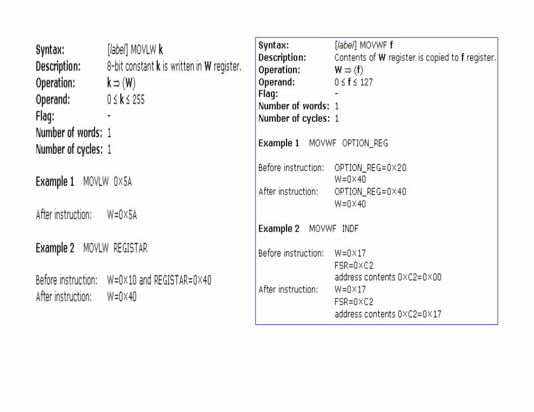
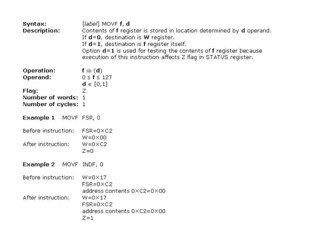
Data transferTransfer of data in a MC is done between W register and an 'f' register.
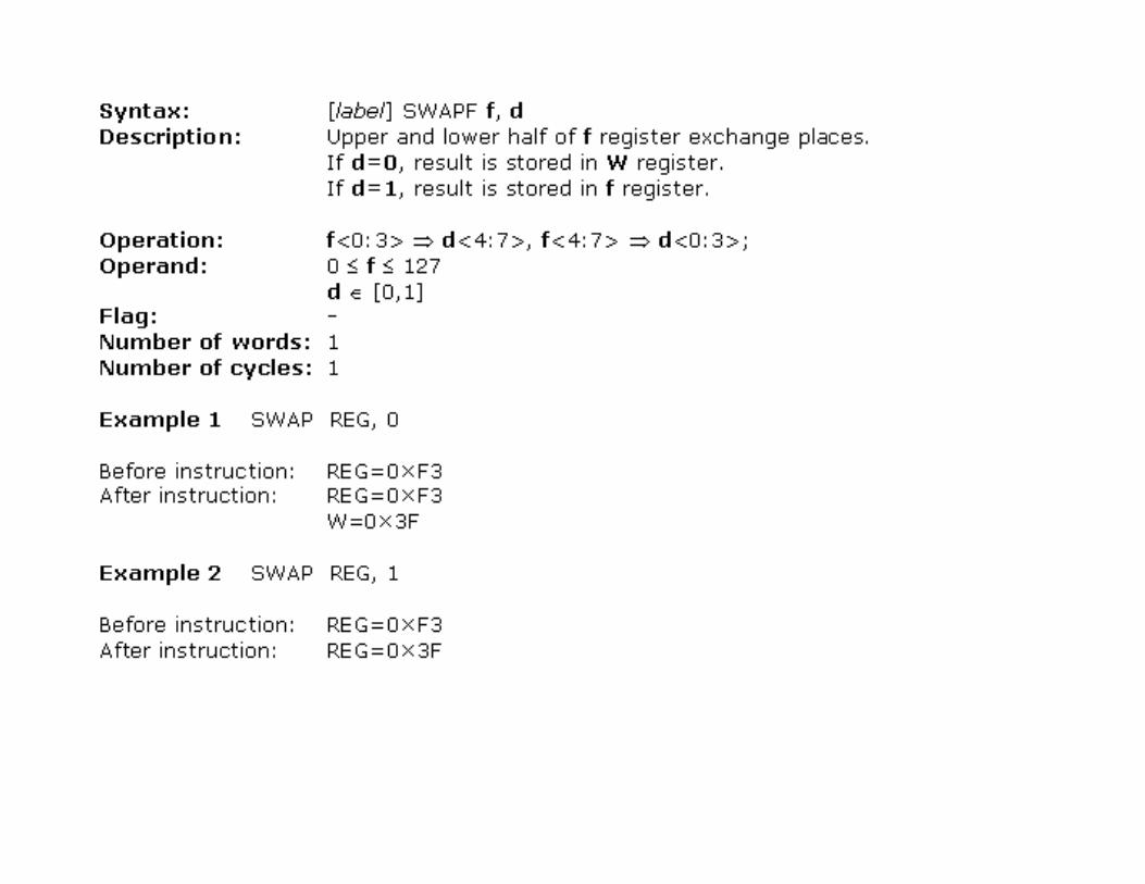
These instructions provide for:- a constant being written in W register (MOVLW)- data to be copied from W register onto RAM.- data from RAM to be copied onto W register (or on the same RAM location, at which point only the status of Z flag changes). -Instruction CLRF writes constant 0 in 'f ' register, - Instruction CLRW writes constant 0 in register W. - SWAPF instruction exchanges places of the 4-bit nibbles field inside a register.
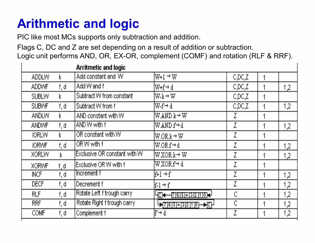
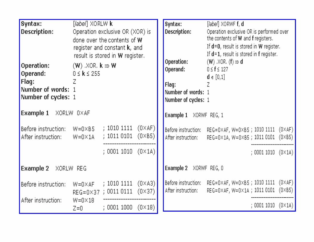
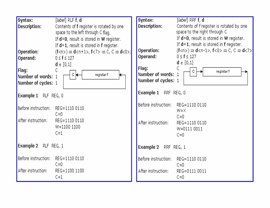
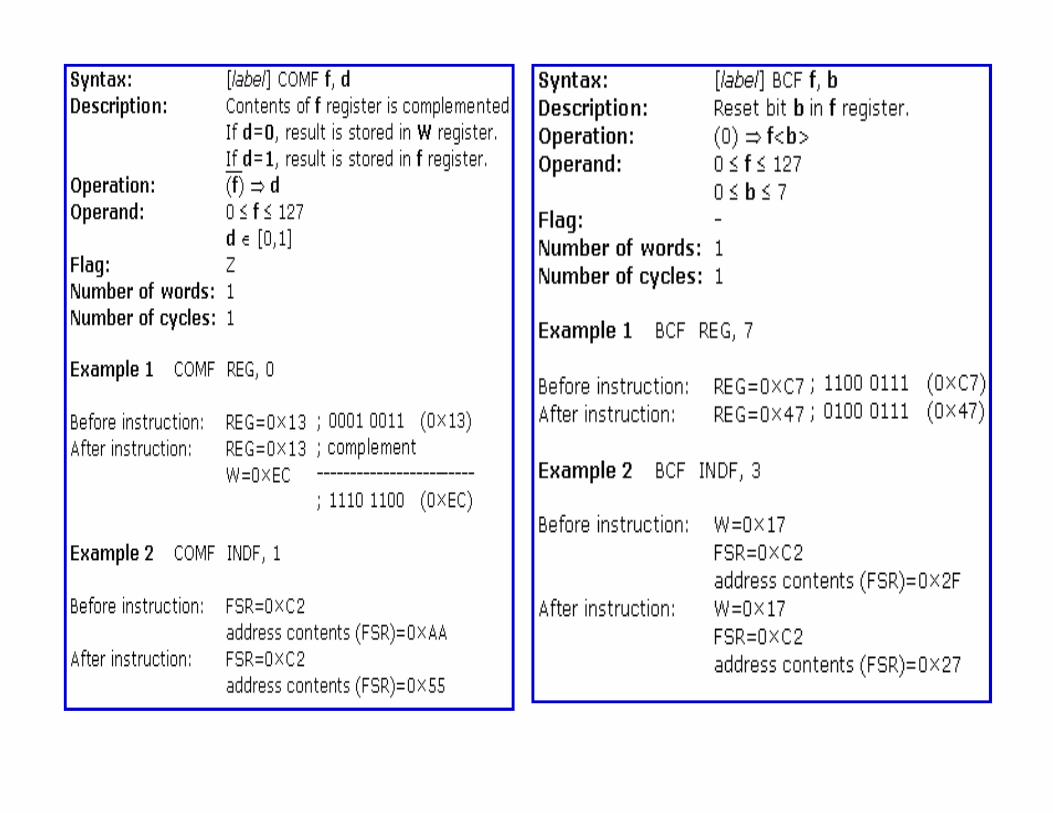
Arithmetic and logicPIC like most MCs supports only subtraction and addition. Flags C, DC and Z are set depending on a result of addition or subtraction.Logic unit performs AND, OR, EX-OR, complement (COMF) and rotation (RLF & RRF).
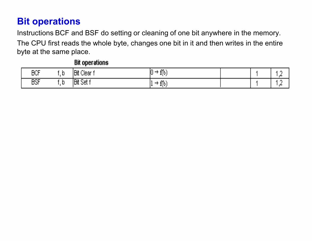
Bit operationsInstructions BCF and BSF do setting or cleaning of one bit anywhere in the memory. The CPU first reads the whole byte, changes one bit in it and then writes in the entire byte at the same place.
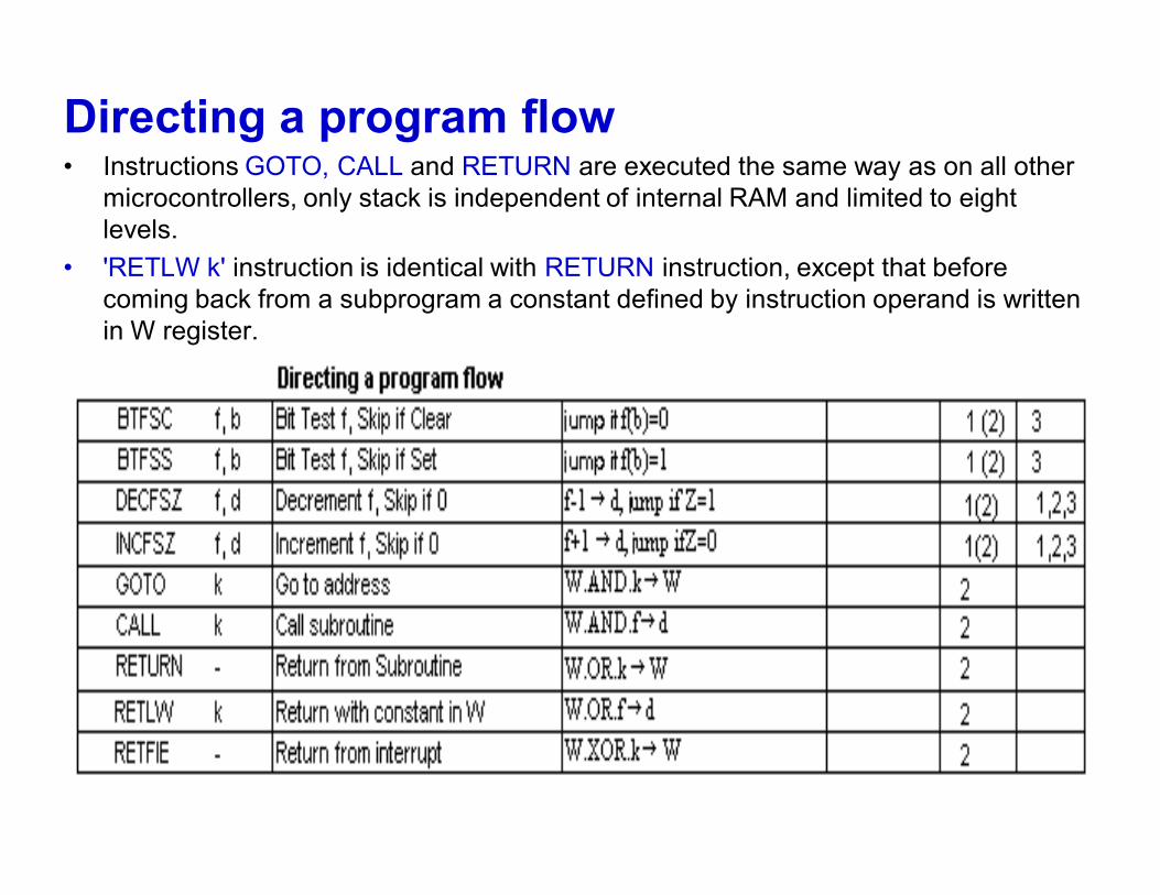
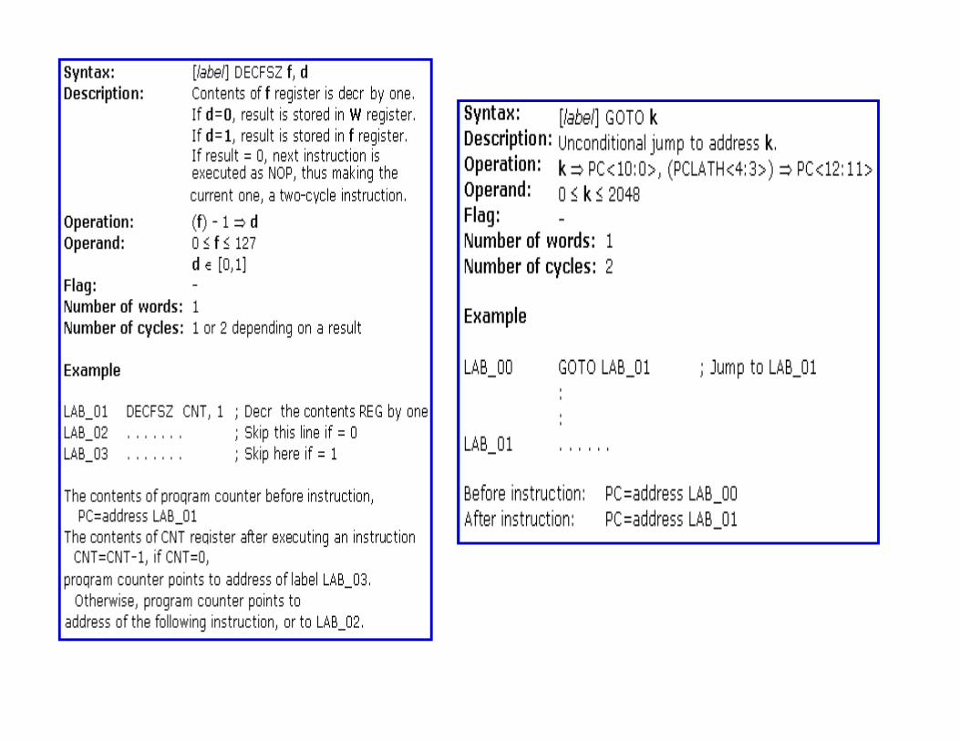
Directing a program flow• Instructions GOTO, CALL and RETURN are executed the same way as on all other
microcontrollers, only stack is independent of internal RAM and limited to eight levels.
• 'RETLW k' instruction is identical with RETURN instruction, except that before coming back from a subprogram a constant defined by instruction operand is written in W register.
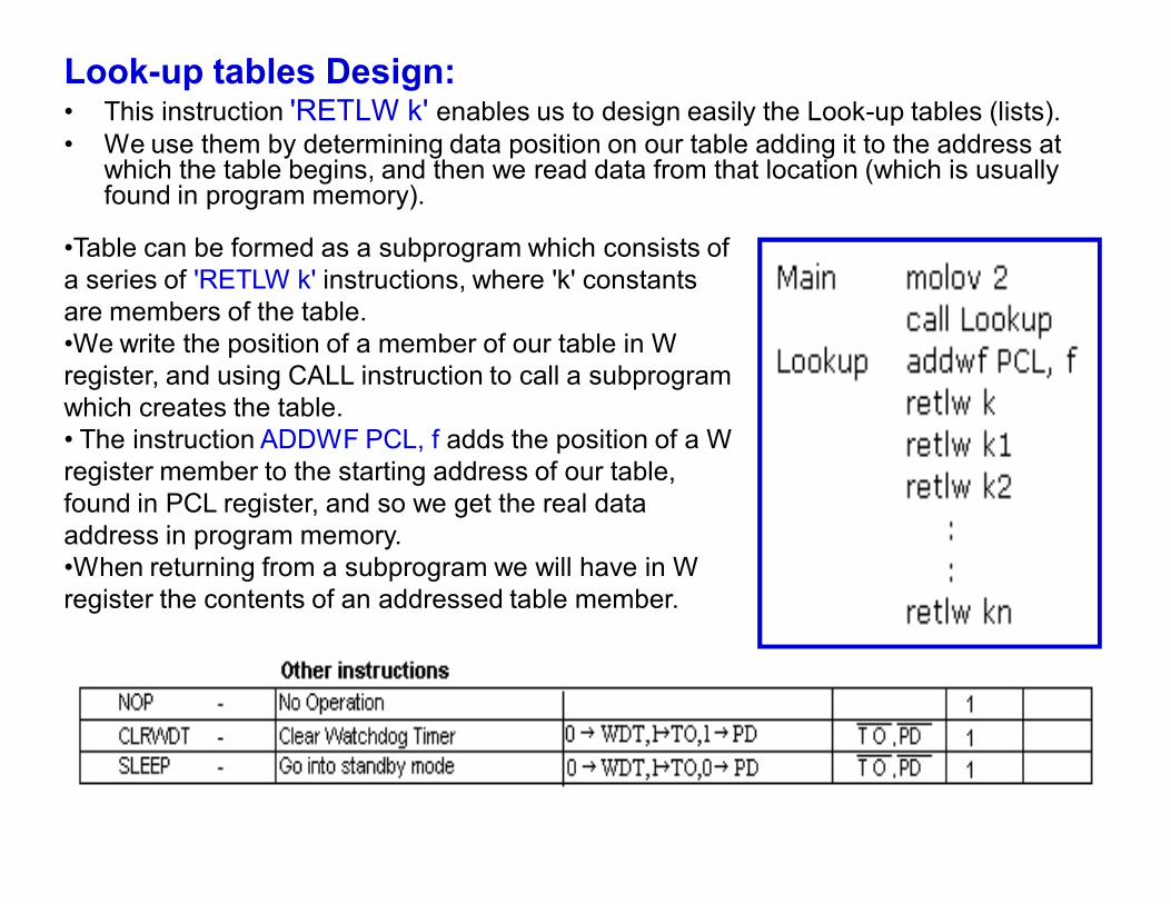
Look-up tables Design:• This instruction 'RETLW k' enables us to design easily the Look-up tables (lists). • We use them by determining data position on our table adding it to the address at
which the table begins, and then we read data from that location (which is usually found in program memory).
•Table can be formed as a subprogram which consists of a series of 'RETLW k' instructions, where 'k' constants are members of the table.•We write the position of a member of our table in W register, and using CALL instruction to call a subprogram which creates the table. • The instruction ADDWF PCL, f adds the position of a W register member to the starting address of our table, found in PCL register, and so we get the real data address in program memory. •When returning from a subprogram we will have in W register the contents of an addressed table member.
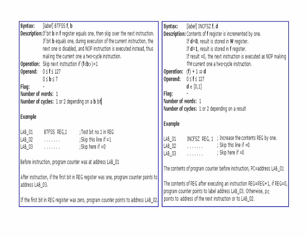
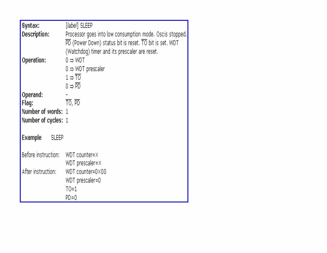
Instruction Execution PeriodAll instructions are executed in one cycle except for conditional branch instructions if condition was true, or if the contents of program counter was changed by some instruction. In that case, execution requires two instruction cycles, and the second cycle is executed as NOP (No Operation). Four oscillator clocks make up one instruction cycle. If we are using an oscillator with 4MHz frequency, the normal time for executing an instruction is 1 µs, and in case of conditional branching, execution period is 2 µs.