Embedded Surface Mount Triaxial Accelerometer · Embedded Surface Mount Triaxial Accelerometer...
27
Embedded Surface Mount Triaxial Accelerometer Robert D. Sill Senior Scientist PCB Piezotronics Inc. 951 Calle Negocio, Suite A San Clemente CA, 92673 (877) 679 0002 x2954 [email protected] Abstract 18566 59 th Fuze Conference, NDIA 6560, Charleston, SC May 3 – 5, 2016
Transcript of Embedded Surface Mount Triaxial Accelerometer · Embedded Surface Mount Triaxial Accelerometer...

Embedded Surface Mount Triaxial Accelerometer
Robert D. Sill Senior Scientist
PCB Piezotronics Inc. 951 Calle Negocio, Suite A San Clemente CA, 92673
(877) 679 0002 x2954 [email protected]
Abstract 18566 59th Fuze Conference, NDIA 6560, Charleston, SC
May 3 – 5, 2016
Embedded Surface Mount Triaxial Accelerometer
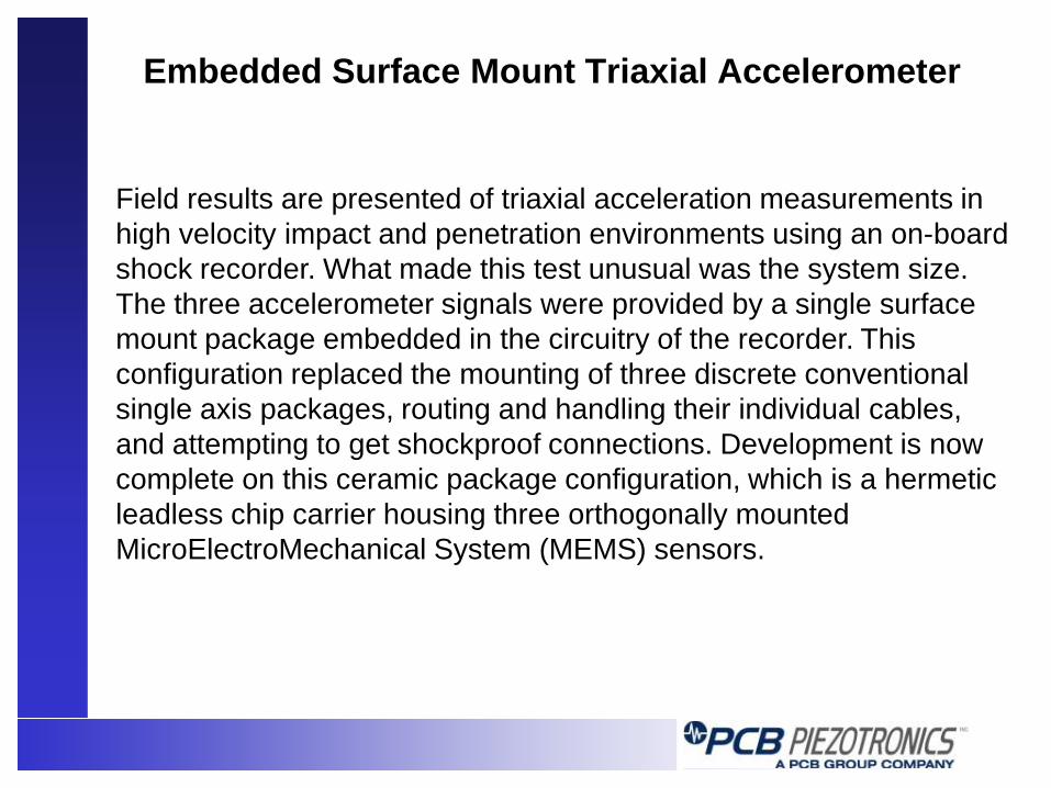
Field results are presented of triaxial acceleration measurements in high velocity impact and penetration environments using an on-board shock recorder. What made this test unusual was the system size. The three accelerometer signals were provided by a single surface mount package embedded in the circuitry of the recorder. This configuration replaced the mounting of three discrete conventional single axis packages, routing and handling their individual cables, and attempting to get shockproof connections. Development is now complete on this ceramic package configuration, which is a hermetic leadless chip carrier housing three orthogonally mounted MicroElectroMechanical System (MEMS) sensors.

Introduction to PR MEMS
•Wheatstone bridge of semiconductor strain gages grown in single crystal silicon
•High piezoresistance gage factor, fully active, transverse (linear) gages, low zero shift, DC coupled
•Advanced wafer etching and fabrication techniques
•Hermetic sandwich of three wafers: active Core wafer sandwiched between Lid and Base wafers, which also function as mechanical stops for over-range survivability
MEMS (MicroElectroMechanical System) PR (PiezoResistive)

Damped PR MEMS Accelerometers Advanced design matches bandwidth to shock applications
– Resonance frequencies are intentionally low, and internal displacements are relatively large (compared to legacy MEMS shock sensors), enabling damping
– Single DOF above resonance acts as 2 pole filter
– Squeeze film damping reduces resonant amplification
– 2kG 20kG 60kG full scale 0.7 0.05 0.02 damping 25kHz 65kHz 160kHz resonance 3kΩ 5kΩ 5kΩ resistance

Damped vs. Undamped MEMS
In Hopkinson bar tests the PCB sensor showed some low Q resonant amplification during the initial pulse, and the legacy sensor (20kG) showed extremely high Q response after the fixture broke away from the bar.
-30000
-20000
-10000
0
10000
20000
30000
40000
200 400 600 800 1000 1200 1400 1600
Time (micro sec)
Acce
lerat
ion
(Gs)
EndevcoPCBQuartz
Credit: D. Frew and H. Duong of Sandia National Laboratory

Damping vs. Mechanical Isolation
A mechanical-isolation package was designed to prevent failure of high Q legacy sensor due to resonant amplification and over range from explosive events and metal-to-metal impacts. The test was ~100 pneumatic metal-to-metal hammer blows in <2 seconds, each ~10kG peak, in direction of sensitive axes. PCB damped sensor was mounted directly to test article alongside mechanically-isolated legacy sensors (one each of 20kG and 60kG versions).
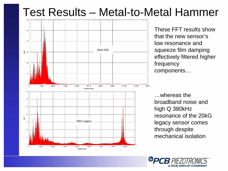
Test Results – Metal-to-Metal Hammer These FFT results show that the new sensor’s low resonance and squeeze film damping effectively filtered higher frequency components… …whereas the broadband noise and high Q 380kHz resonance of the 20kG legacy sensor comes through despite mechanical isolation

Damping Curve Fit Shaker tests indicate the sensitivity frequency response matches a single DOF system with 65kHz resonance and 0.05 damping. Overlaying an ideal sensitivity frequency response curve on the broadband hammer test FFT (this time plotted on logarithmic axes) shows the damping is more effective than expected at frequencies higher than the primary resonance. Associated with the damping was a phase delay of ~4 microseconds.
Conclusions Regarding Damping
•Squeeze film damping may eliminate need for mechanical filtering when measuring penetration and pyrotechnic events.
•Resolution can be improved over undamped sensors: gain of conditioning and data acquisition can be scaled to measurement rather than the high Q of undamped sensors.
•Data acquisition can be simpler: Sample rate and filter requirements to avoid aliasing of new sensor are much less severe than legacy sensor.
•Significant miniaturization is possible over mechanical isolation particularly by putting the sensor on the circuit board with surface mount options.
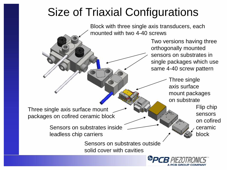
Size of Triaxial Configurations Block with three single axis transducers, each mounted with two 4-40 screws
Two versions having three orthogonally mounted sensors on substrates in single packages which use same 4-40 screw pattern
Three single axis surface mount packages on substrate
Three single axis surface mount packages on cofired ceramic block
Flip chip sensors on cofired ceramic block
Sensors on substrates outside solid cover with cavities
Sensors on substrates inside leadless chip carriers

Successful SMT Triax
Cofired ceramic leadless chip carrier with hermetically sealed cover and solderable surface mount pads. Includes evolutionary internal improvements for enhanced overrange survivability and reduction of mounting strain effects.
Testing SMT Accelerometers is Difficult
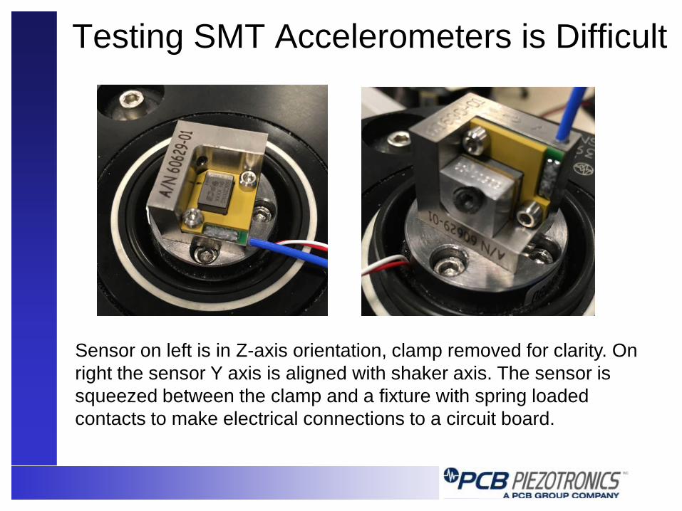
Sensor on left is in Z-axis orientation, clamp removed for clarity. On right the sensor Y axis is aligned with shaker axis. The sensor is squeezed between the clamp and a fixture with spring loaded contacts to make electrical connections to a circuit board.

Frequency Response - 20kG FS - Z axis
This is the Z axis of a 20kG full scale sensor, which has 65kHz resonance, allowing passage (and some amplification of) of the 35kHz and 45 kHz shaker and fixture resonances.

Frequency Response - 2kG FS - Z axis
For better resolution at 10G, this test was performed on a 2kG full scale damped sensor, Z axis orientation. Note the effect of damping on the higher frequency glitches.

Frequency Response - 2kG FS - Y axis
This 2kG full scale sensor, Y axis orientation, shows the effect of the low shear strength of the padding and materials used in the fixture.
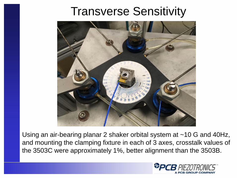
Using an air-bearing planar 2 shaker orbital system at ~10 G and 40Hz, and mounting the clamping fixture in each of 3 axes, crosstalk values of the 3503C were approximately 1%, better alignment than the 3503B.
Transverse Sensitivity
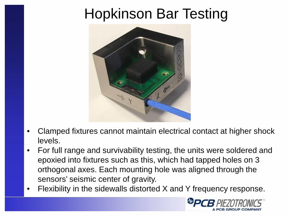
• Clamped fixtures cannot maintain electrical contact at higher shock levels.
• For full range and survivability testing, the units were soldered and epoxied into fixtures such as this, which had tapped holes on 3 orthogonal axes. Each mounting hole was aligned through the sensors’ seismic center of gravity.
• Flexibility in the sidewalls distorted X and Y frequency response.
Hopkinson Bar Testing
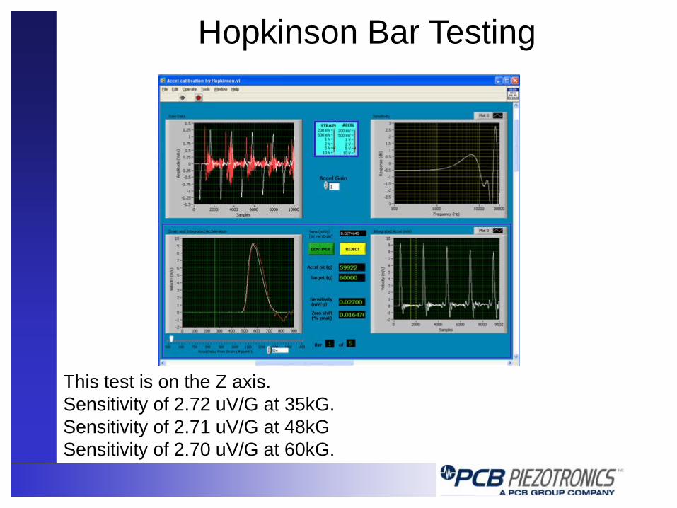
This test is on the Z axis. Sensitivity of 2.72 uV/G at 35kG. Sensitivity of 2.71 uV/G at 48kG Sensitivity of 2.70 uV/G at 60kG.
Hopkinson Bar Testing
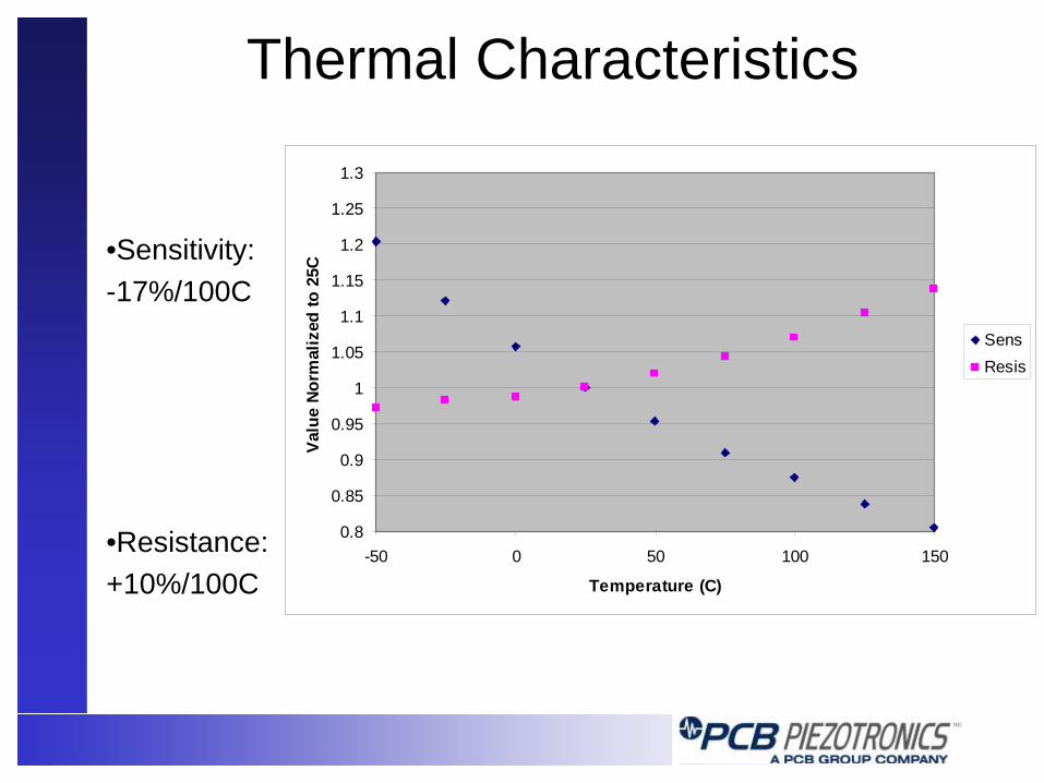
Thermal Characteristics
•Sensitivity: -17%/100C
•Resistance: +10%/100C
0.8
0.85
0.9
0.95
1
1.05
1.1
1.15
1.2
1.25
1.3
-50 0 50 100 150
Temperature (C)
Valu
e No
rmal
ized
to 2
5CSensResis

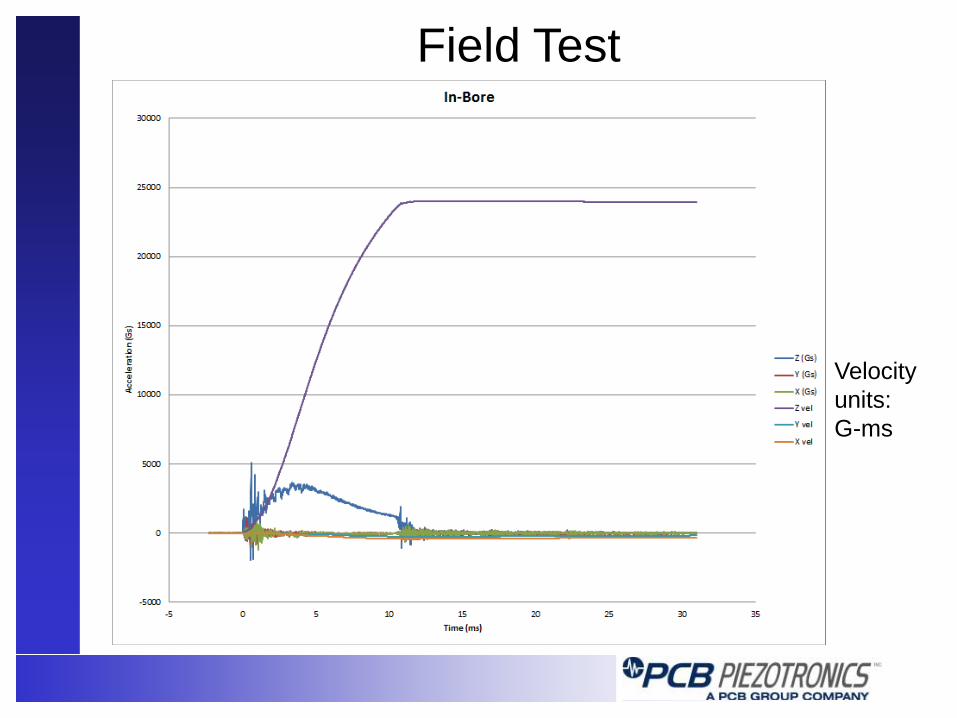
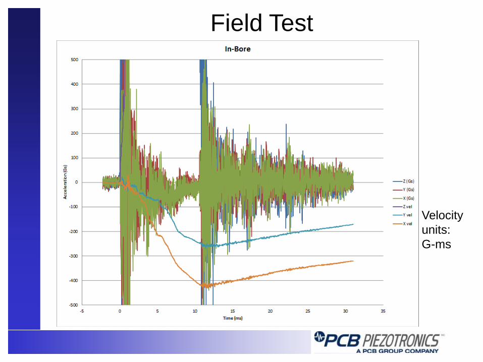
Field Test
Credit: Brian Tacke of Syntronics
Field Test
Velocity units: G-ms
Field Test
Velocity units: G-ms

Cannon Test Syntronics built a 4” bore air cannon facility in 2009 to shock test their line of gun-hardened electronics, including data recorders, telemetry transmitters, and a variety of instrumentation products featuring accelerometers, rate gyros, magnetometers, and GPS receivers. The cannon has a fully instrumented tube with pressure transducers and laser detectors at one foot intervals for velocity determinations. Embedded triaxial accelerometers are successfully used to characterize >35 kG shocks with durations of >200 us.
Credit: Brian Tacke of Syntronics

Cannon Test Peak loads include unfiltered dynamic structural response of the canister on top of rigid body deceleration. Correlations between axial and transverse responses hint that bending modes were the primary source of transverse readings.
Credit: Brian Tacke of Syntronics
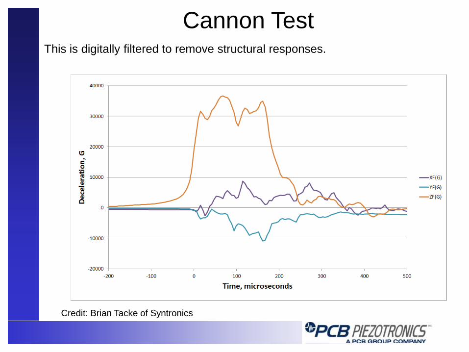
Cannon Test This is digitally filtered to remove structural responses.
Credit: Brian Tacke of Syntronics
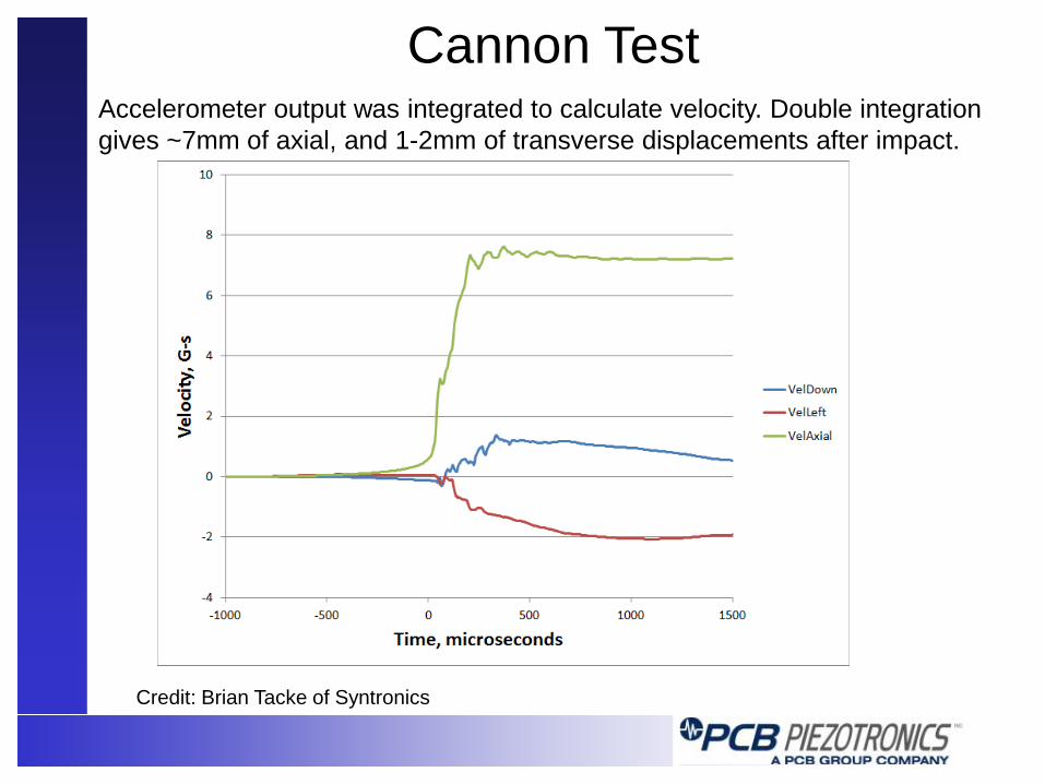
Cannon Test Accelerometer output was integrated to calculate velocity. Double integration gives ~7mm of axial, and 1-2mm of transverse displacements after impact.
Credit: Brian Tacke of Syntronics
Summary
• Damped PR MEMS accelerometers allow accurate characterization of high velocity shock and penetration events
• Surface mount single and triaxial packages provide miniaturization
• Alignment is critical to avoid transverse sensitivity
• Structural dynamics complicate interpretation of
transverse axes