Embedded programming in RTOS VxWorks for PROFIBUS VME interface card
139
1 Embedded programming in RTOS VxWorks for PROFIBUS VME interface card A PROJECT REPORT Submitted by SHELAT RUTUL B. (ER NO.090130117001) CHANDOLIA RINKU K. (ER NO. 090130117023) In fulfillment for the award of the degree Of BACHELOR OF ENGINEERING in INSTRUMENTATION & CONTROL Government Engineering College, Sector 28, Gandhinagar. Gujar at T ec hnol ogical Uni versity, Ahme dabad MAY 2013 Government Engineering College, Sector 28, Gandhinagar.
-
Upload
rinku-chandolia -
Category
Technology
-
view
120 -
download
7
Transcript of Embedded programming in RTOS VxWorks for PROFIBUS VME interface card
1
Embedded programming in RTOS VxWorks for
PROFIBUS VME interface card
A PROJECT REPORT
Submitted by
SHELAT RUTUL B. (ER NO.090130117001)
CHANDOLIA RINKU K. (ER NO. 090130117023)
In fulfillment for the award of the degree
Of
BACHELOR OF ENGINEERING
in
INSTRUMENTATION & CONTROL
Government Engineering College, Sector 28,
Gandhinagar.
Gujarat Technological University, Ahmedabad
MAY 2013
Government Engineering College, Sector 28,
Gandhinagar.

2
INSTRUMENTATION & CONTROL 2013
CERTIFICATE
Date: This is to certify that the dissertation entitled “Embedded programming in
RTOS VxWorks for PROFIBUS VME interface card” has been carried out
by SHELAT RUTUL B. (ER NO.090130117001) and CHANDOLIA RINKU
K. (ER NO. 090130117023) under our guidance in fulfillment of the degree of
Bachelor of Engineering in INSTRUMENTATION & CONTROL (7th
& 8th
Semester) of Gujarat Technological University, Ahmedabad during the
academic year 2012 - 2013.
Guides: Mr. MAHESH KUMAR KUSHWAH
Electrical engineer. SE, ECRH
group ITER-INDIA(IPR)
&
Mr. DINESH KUMAR SHARMA
Engineer-SE, SST-1 power system
group(IPR)
PROF. RATHOD SWATI YASHVANTBHAI
(INTERNAL) Head of the Department
(HOD)
PROF. AMAR D. RATHOD

3
ACKNOWLEDGEMENT
We express our sincere gratitude and thanks to all those who helped us in the completion
of this project. Of all the persons who have helped us, we would first of all like to thank Mr.
Mahesh Kumar Kushwah, Electrical Engineer, SE, ECRH group, ITER-India (IPR) & Mr.
Dinesh Kumar Sharma, Engineer SE, IPR for their able guidance because of whom we are doing
our project and who helped us at each and every stage of our project.
We are also thankful to Prof. Swati Rathod who guided us as internal project guide in our
college.
They a re very co-operative and always eager to solve our problems. They
always encouraged us to work hard and have given useful suggestions on how to solve the
errors. We are grateful to them for their prolonged interest in our work and excellent
guidance. They have been a constant source of motivation for us. By their uncompromising
demand for quality and their insistence for meeting the deadlines, we could do such an excellent
work. They have shown us a way to pursue excellence. Their time particularity and tactics of
what to learn and how to learn have helped us stepping into professional world as well as to be
a better person.

4
PREFACE
This report is a result of a group exercise carried out as a part of Academic Project. Our
team underwent for project in the EMBEDDED PROGRAMMING IN RTOS VxWORKS FOR
PROFIBUS VME INTERFACE CARD and we are learning its various skills during the process.
We will carry out the complete work of preparing this project individually as well as collectively
and we will learn a lot in this process. Our guides in this endeavor, Mr. Mahesh Kumar Kushwah
& Mr. Dinesh Kumar Sharma are guiding us very well.

5
ABSTRACT
This project is based on real time operating system (RTOS) VxWorks
software in which we are transmitting reference signal from VME (Versa
Module Eurocard ) system to CBP2 (Carrier Board Profibus ) module.
Its main purpose is to transfer reference and ON/OFF data from VME
profibus card to CBP2 module on event.
In this project we have to complete embedded programming in RTOS VxWorks
for carrier board (V6PFB) module and test the same by transferring reference
data from VME based PSCS(Power Supply Control System) to gate pulse
controller mounted on control card of 6RA70 controller on an event.
That reference (current reference acquired from machine control
system) will act as reference data to close loop current control block in simoreg
master drive controller (6RA70 drive controller) controller.

6
List of TABLES
Table No. Name Page No.
3.1 General features of VMEbus 15
3.2 Base address setting of carrier board 20
3.3 Memory map for AVME 9668 21
3.4 DIP switch setting 26
3.5 Power supply selection 26
3.6 IP330 space identification (ID) PROM 27
3.7 I/O space address map for IP33o 28
3.8 Call routine description 40
5.1 Technical specification of V6PFB 86
5.2 V6PFB jumper setting of base address 88
6.1 Pin function of CUD1 91

7
List of FIGURES
Figure No. Name Page No.
1.1 Block diagram 12
3.1 VMEbus wiring connections 16
3.2 Carrier board block diagram 22
3.3 Actual carrier board image 23
3.4 Actual IP330 image 27
3.5 Tornado shell image 32
3.6 Target simulator 34
3.7 Implementation of IP330 in carrier board 35
3.8 Sample programme 36
3.9 Analog input 37
3.10 Output hyper terminal window for sample programme 38
3.11 Semaphore programme 41
3.12 Semaphore programme output 42
3.13 Programme of Interrupt Service routine 44
3.14 Output of Interrupt Service routine 46
3.15 Programme of multitasking 48
4.1 DP master-parameter set 50
4.2 DP slave-parameter set 50
4.3 Tool bus and menus 51
4.4 Database import dialoge 52
4.5 Selecting files for import 52
4.6 Cofiguration of local PROFIBUS innterface 54
4.7 Parameter for local master class2 55
4.8 Template parameters 55
4.9 Setting dialoge 56
4.10 Project pane 57
4.11 Project pane with a master and three slaves in a project 58
4.12 Result of Auto-configuration 58
4.13 Association of slave to group 59
4.14 Master parameters 60
4.15 Net parameters 61
4.16 Basic slave parameters 62
4.17 Selecting modules 63
4.18 Advanced set up of a slave 64
4.19 Extented user parameters 65
4.20 Edit menu with new import "import slaves" 66
4.21 Error message when importing slaves 66
4.22 Master configuration window 68
4.23 Slave configuration window 68
4.24 Compile binary file 73
5.1 Token procedure in PROFIBUS 76
5.2 OSI level of PROFIBUS 79
5.3 PROFIBUS DP 80

8
5.4 PROFIBUS cable image 82
5.5 Actual image of VME interface card 83
5.6 Function block diagram V6PFB 84
5.7 V6PFB board overview 87
6.1 Internal view of 6RA70 89
6.2 CUD1 90
6.3 LED status of CBP2 99
6.4 Drive monitor active window 103
6.5
Drive monitor response analysis window when NO CONNECTION
with 6RA70 108
6.6 net parameters 111
8.1 Connection between 6RA70 and VME system 129
8.2 Input reference signal 130
8.3 Communication status by viewing LEDs 130
8.4 Drive monitor status for reference signal 131
8.5 Screen shot related to fig.8.4 132
8.6 Data transfer through VME interface card 133

9
Table of Contents
---------------------------------------------------------------------------------------------------
TITLE PAGE NO.
COVER PAGE 1
CERTIFICATE 2
ACKNOWLEDGEMENT 3
PREFACE 4
ABSTRACT 5
LIST OF TABLES 6
LIST OF FIGURES 7
TABLE OF CONTENTS 9
CHAPTER 1 INTRODUCTION 12
1.1 INTRODUCTION 12
CHAPTER 2 PROBLEM SUMMARY & TOOLS 13
2.1 PROBLEM SUMMARY 13
2.2 TOOLS & COMPONENTS 13
CHAPTER 3 VME SYSTEM 14
3.1 VMEbus SYSTEM 14
3.1.1 INTRODUCTION OF VMEbus 14
3.1.2 GENERAL FEATURES OF VMEbus 14
3.1.3 THE VME64 EXTENSIONS 15
3.1.4 VMEbus APPLICATIONS 17
3.2 VME MODULES 17
3.2.1 CARRIER BOARD MODULE 18
3.2.2 IP INPUT ANALOG MODULE 23
3.3 PC WITH RTOS VxWorks 28
3.3.1 FACILITIES OF VxWorks REAL TIME OPERATING
SOFTWARE
29
3.4 RESULT ANALYSIS FOR SIMPLE ROUTINE &
SEMAPHORES PROGRAMME
34

10
3.4.1 SIMPLE ROUTINE PROGRAMME 34
3.4.2 WHAT IS SEMAPHORE? 38
CHAPTER 4 DP CONFIGURATION 49
CHAPTER 5 PROFIBUS & PROFIBUS VME INTERFACE CARD 74
5.1 PROFIBUS 74
5.2 PROFIBUS VME INTERFACE CARD 83
CHAPTER 6 6RA70 CHASIS & DRIVE MONITOR 89
6.1 6RA70 CHASIS 89
6.2 DRIVE MONITOR 99
6.2.1 DRIVE MONITOR OVERVIEW 99
6.2.2 DRIVE MONITOR CONFIGURATION 108
CHAPTER 7 PROGRAMME FILE OF SIMPLE DP 112
CHAPTER 8 EXECUTION OF DATA TRANSFER BETWEEN CBP2
MODULE & VME INTERFACE CARD THROUGH
PROFIBUS
129
APPLICATION 137
CONCLUSION 138
REFERENCE 139

11
THIS PAGE IS LEFT BLANK
INTENTIONALLY.

12
Chapter 1
Introduction
1.1 Introduction The problem Embedded programming in RTOS Vxworks for PROFIBUS VME Interface
card is related to interfacing or communication of two different system. One system is VME
system which receives reference and status of DC power supply and second CBP2 module
mounted on 6RA70 simoreg master drive controller.
In this project we are transferring reference signal from VMEsystem to CBP2 module
through profibus, as shown in block diagram.
Fig.1.1 Block diagram

13
CHAP TER 2
PROBLEM SUMMARY & TOOLS
2.1 PROBLEM SUMMARY
DC power supply both TF (toroidal field) and PF (poloidal field) are very much integral
part of SST-1(steady state super conducting tokamak) machine. These TF and PF power supplies
are twelve pulse SCR based converter system. These DC coil power supply are connected to
VME bus based control system. And ultimately this power supply control system (PSCS) is
connected to central machine control system.
Here the communication link plays a pivotal role for transferring reference and status of
DC power supply to PSCS and Machine control system. The reference signal for current in the
individual power supply will be transmitted to VME on reflective memory FO link system. From
VME system to all PF power supply a dedicated with redundancy link profibus system will be
used for transferring reference data to all PF power supply.
PF power supply has 6RA70 DC simoreg master (drive controller) for gate firing control
of 12 pulse converter system. A CBP2 module is mounted on the 6RA70 control card for
external fast communication (12 Mbaud speed).
Now the problem arises in interlinking two different systems (one VME and another is
CBP2 module mounted on 6RA70 controller). To interlink effectively, we have a module
Profibus VME interface card.
In this project we have to complete embedded programming in RTOS VxWorks for
V6PFB module and test the same by transferring reference data from VME based PSCS to gate
pulse controller mounted on control card of 6RA70 controller on an event.
2.2 TOOLS & COMPONENTS
To solve the problem, we are using different types of tools & components. These are as
follows:
VME system
VME module
PC with RTOS VxWorks
DP Configuration Software (SOFTING)
Profibus – VME Interface card (V6PFB)
CBP2 installed in 6RA70 drive controller
Oscilloscope and multimeter

14
CHAPTER 3
VME SYSTEM
3.1 VMEbus SYSTEM
3.1.1 Introduction of VMEbus:-
VMEbus is a computer architecture. The term 'VME' stands for VERSAmodule
Eurocard. VMEbus was originally a combination of the VERSAbus electrical standard, and
the Eurocard mechanical form factor. The VMEbus architects were charged with defining a
new bus that would be microprocessor independent, easily upgraded from 16 to 32-bit data
paths, implement a reliable mechanical standard and allow independent vendors to build
compatible products.
No proprietary rights were assigned to the new bus, which helped stimulate third party
product development. Anyone can make VMEbus products without any royalty fees or
licenses. Eurocard is a term which loosely describes a family of products based around the
DIN 41612 and IEC 603-2 connector standards, the IEEE 1101 PC board standards and the
DIN 41494 and IEC 297-3 rack standards.
When VMEbus was first developed, the Eurocard format had been well established in
Europe for several years. A large body of mechanical hardware such as card cages, connectors
and sub-racks were readily available. The pin and socket connector scheme is more resilient
to mechanical wear than older printed circuit board edge connectors.
The ANSI, VITA, IEC and IEEE standards made VMEbus a publicly defined
specification. Since no proprietary rights are assigned to it, vendors and users need not worry
that their products will become obsolete at the whim of any single manufacturer.
Since its introduction, VMEbus has generated thousands of products and attracted hundreds of
manufacturers of boards, mechanical hardware, software and bus interface chips. It continues
to grow and support diverse applications such as industrial controls, military,
telecommunications, office automation and instrumentation systems.
3.1.2 General Features of VMEbus
Since 1970s, a continuous modification and improvement in the VME system takes

15
place, the main general features of VMEbus are as shown in table 3.1
Item Specification Notes
Architecture Master/Slave
Transfer Mechanism Asynchronous, with both
multiplexed & non-
multiplexed bus cycles
No central synchronization
clock
Addressing Range 16, 24, 32, 40 or 64-bit Address range selected
dynamically
Data Path Width 8, 16, 24, 32 or 64-bit Data path width selected
dynamically
Parity Protection No
Data Transfer Rate 0 – 500 Mbyte/sec Experimental VME320
backplane to 500 Mbyte/sec
Interrupts 7 levels Priority interrupt system
with STATUS/ID
Multiprocessing Capability 1 – 21 processor Flexible bus arbitration
Live Insertion Capability Yes High Availability VME64
Control & Status Registers
(Plug & Play Support)
Yes VME64
VME64x
Mechanical Standard 3U single-height Eurocard
6U double-height Eurocard
9U (optional standard)
160 x 100 mm Eurocard
160 x 233 mm Eurocard
367 x 400 Eurocard
User Defined I/O Yes Through the front panel
Maximum Number of Card
Slots in Backplane
21 The number of cards is
limited by how many
boards, located on 0.8”
centers, can be placed into
a 19” rack panel
Table 3.1:- General Features of VMEbus
3.1.3 The VME64 Extensions
In 1997 the VITA Standards Organization (VSO) adopted a superset to the VME64
standard. The latest standard is called the VME64 Extensions (VME64x). VME64x adds new
capabilities such as:
A new 160 pin connector

16
family.
A 95 pin P0/J0 connector.
3.3 V power supply pins.
More +5 VDC power supply
pins.
Geographical addressing.
Higher bandwidth bus cycles
(up to 160 Mbytes/sec).
141 more user-defined I/O pins.
Rear plug-in units
(transition modules).
Live insertion / hot-swap
capability.
Injector / ejector locking handles.
EMC (ElectroMagnetic Compatible)
front panels.
ESD (Electrostatic Discharge) features.
Fig.3.1 VMEbus wiring connection
The VME64x standard also lays the groundwork for the High Availability and Live
Insertion (Hot Swap) VME64x standards.
All legacy VME and VME64 modules are forward compatible to VME64x backplanes
and sub-racks. That means that older bus modules can be plugged into newer systems.
In general, the reverse is also true. Bus modules designed to the VME64x standard are
also backward compatible with older backplanes and subracks. For example, the new 160 pin
connectors can be plugged into an older backplane. However, there are a few exceptions to this.
For example, if a board requires the new +3.3 VDC power supplies, then it will not work in an
older backplane (which does not have these power pins).
The VME64x standard describes many optional features. However, the standard insists
that a minimum set of features be present on boards and backplanes before they are considered to
be VME64x compliant. All of the other features in the standard are considered optional. For
example, the minimum features that must be present on 6U modules include:
160 pin connectors.

17
All defined grounds must be connected (row 'd' is optional).
The minimum features that must be present on a 6U backplane include:
160 pin connectors.
All defined grounds must be connected.
Monolithic PCB (i.e. must include both J1 and J2 connectors).
Geographical address pins.
Must route and terminate all VME64 and VME64x bused signal lines.
Power connection and distribution for +5V, +3.3V, +/- 12V, +/- V1, +/- V2 and VPC.
If rear (user defined) I/O pins are supported, then the rear connections must comply
with the IEEE 101.11 rear I/O transition board standard.
3.1.4 VMEbus Applications
VMEbus is used in a wide variety of applications. In many cases, the VMEbus system
design has been tailored to support specialized applications as well. Some of the most popular
applications are:
Industrial controls: factory automation, robotics, injection molding machines,
automotive body assembly and painting, sawmill controls, metal working, steel
manufacturing, cardboard cutters and many others.
Military: battlefield command & control systems, ground and flight radar control
systems, tank and gun controls, communications, avionics and many others.
Aerospace: avionics, fly-by-wire control systems, in-flight video servers, spacecraft
experiment control, missile countdown sequencers, and many others. In 1998 the
Mars Pathfinder used a VMEbus computer to control spacecraft operation on the
planet Mars.
Transportation: railway controls, smart highway systems and light-rail transit
systems.
Telecom: advanced intelligent node (AIN) switch gear, cellular telephone base
stations, satellite uplink and downlinks and telephone switches. VMEbus live
insertion capabilities were also designed for this application.
Simulation: aircraft flight, earthquake, metal fatigue and various military simulation
systems.
Medical: CATSCAN imaging, MRI imaging and various acoustical systems.
High Energy Physics: particle accelerators, particle detectors.
General business: network routers, servers, copy machines and high-speed printers.
3.2 VME Modules:
In VME System, there are 21 slots these slots used for mounting the VME carrier boards
modules. These carrier boards having slots for IP industrials I/O pack. So in VME system there
is basically two modules are used.

18
These are:
1.Carrier board module (AVME 9668)
2.IP analog I/O module (IP330 analog input module)
3.2.1 Carrier board module
The Carrier board used to carries the IP analog input/output and digital input/output
modules on it, than it is mounted in VMEsystems any one slots for programme writing.
The AVME9668 Series of VMEbus cards are carriers for the Industrial I/O Pack (IP)
mezzanine board field I/O modules. The carrier boards facilitate a modular approach to system
assembly, since each carrier can be populated with any combination of analog input/output and
digital input/output IP modules.
Thus, the user can create a board which is customized to the application which saves
money and space - a single carrier board populated with IP modules may replace several
dedicated function VMEbus boards.
This standard VMEbus 6U size, with support for up to four IP modules.
KEY AVME9668 FEATURES
The main features of AVME carrier board are as follow:
Interface for Four IP Modules : Provides an electrical and mechanical interface for up to
four industry standard IP modules. IP Modules are available from Acromag and other
vendors in a wide variety of Input/Output configurations to meet the needs of varied
applications.
Supports accesses to IP input/output, memory, and ID PROM data spaces.
Full IP Register Access - Makes maximum use of logically organized programmable
registers on the carrier boards to provide for easy configuration and control of IP
modules. The only hardware jumper settings required on the carrier boards set the base
address of the card in the VMEbus short I/O space.
LED Displays Simplify Debugging - On board LED's are dedicated to each IP module to
give a visual indication of successful IP accesses.
Front Panel Connectors Access I/O - Front panel access to field I/O signals is provided
via industry standard 50-pin headers. A separate header is provided for each IP module.
All IP module I/O signals can be connected to SCSI-2cables from the front panel without
interference from boards in adjacent slots.
Optional Screw Termination Panel - Model supports field connection via screw terminals
using the optional DIN rail mount termination panels.
Memory Space Access Support - IP memory space accesses are supported and software
configurable from1Mbyte to 8Mbytes in the VMEbus standard address space.

19
Supports Two Interrupt Channels per IP - Up to two interrupt requests are supported for
each IP. The VMEbus interrupt level is software programmable. Additional registers are
associated with each interrupt request for control and status monitoring.
Supervisory Circuit for Reset Generation - A microprocessor supervisor circuit provides
power-on, power- off, and low power detection reset signals to the IP modules per the IP
specification.
Individually Fused and Filtered Power – Fused and filtered +5V, +12V, and -12V DC
power is provided to the IP modules via passive filters present on each supply line
serving each IP. This provides optimum filtering and isolation between the IP modules
and the carrier board and allows analog signals to be accurately measured or reproduced
on IP modules without signal degradation from the carrier board logic signals.
Interrupt Support - I (1-7) interrupter D16/D08 (O). Up to two interrupt requests are
supported for each IP module. The VMEbus interrupt level is software programmable.
Carrier board software programmable registers are utilized as interrupt request control
and status monitors.
VMEbus INTERFACE CONFIGURATION
The carrier board is shipped from the factory configured as follows: -Carrier board with
VMEbus Short I/O Base Address of 0000H. Board will respond to both Address Modifiers 29H
and 2DH.
Registers on the carrier board plus the I/O and ID spaces on any installed IP modules will
be accessible.
Programmable software registers default to IP memory space (VMEbus standard address
space) accesses disabled.
Programmable software registers default to IP interrupt requests disabled and VMEbus
interrupt level-none.
(A) Address Decode Jumper Configuration
The carrier board interfaces with the VMEbus as a 1K byte block of address locations in
the VMEbus short I/O address space (refer to Section 3 for memory map details). J1 decodes
the six most significant address lines A10 through A15 to provide segments of 1K address
space. The configuration of the jumpers for different base address locations is shown in Table
2.1. "IN" means that the pins are shorted together with a shorting clip. "OUT" indicates that the
clip has been removed. As in table 3.2.

20
Base
Addr*
(Hex)
A15
(11&12
)
A14 (9&10)
A13 (7&8)
A12 (5&6)
A11 (3&4)
A10 (1&2)
0000 OUT OUT OUT OUT OUT OUT 0400 OUT OUT OUT OUT OUT IN 0800 OUT OUT OUT OUT IN OUT 0C00 OUT OUT OUT OUT IN IN 1000 OUT OUT OUT IN OUT OUT . . .
.
.
.
.
.
.
.
.
.
. .
.
.
.
.
.
. EC00 IN IN IN OUT IN IN F000 IN IN IN IN OUT OUT F400 IN IN IN IN OUT IN F800 IN IN IN IN IN OUT FC00 IN IN IN IN IN IN
Jumper Selections (J1 Pins)
TABLE 3.2:- Base address setting of carrier board
Thus jumper in /out used for base address setting.For e.g. if all address lines are in, then
the base address is 0xFCFEFCOO. Where the add. FCOO as shown in table.
(B) VMEbus Address Modifiers
No hardware jumper configuration is needed. The carrier board will respond to both
address modifiers 29H and 2DH in the VMEbus short I/O space. This means that both short
supervisory and short non-privileged accesses are supported.
PROGRAMMIG INFORMATION
The board is addressable on 1K byte boundaries in the Short I/O (A16) Address Space.
This Acromag VMEbus non-intelligent slave (carrier board) has a Board Status register, but no
ID PROM. ID PROM’s are provided per the Industrial I/O Pack logic interface specification on
the mezzanine (IP) boards which are installed on the carrier.
Base
Address +
(Hex)
EVEN Byte
D15 D08
ODD Byte
D07 D00
Base Address + (Hex)
0000
↓
007E
IP A
I/O Space
High Byte
IP A
I/O Space
Low Byte
0001
↓
007F
0080
↓
00BE
Not Used
IP A
ID Space
Low Byte
0081
↓
00BF
00C0
↓
00FE
Not Used
Carrier Board
Registers
(See Table 3.1B)
00C1
↓
00FF
0100
↓
017E
IP B
I/O Space
High Byte
IP B
I/O Space
Low Byte
0101
↓
017F
0180
↓
01BE
Not Used
IP B
ID Space
Low Byte
0181
↓
01BF

21
01C0
↓
01FE
Not Used
Not Used
01C1
↓
01FF
0200
↓
027E
IP C
I/O Space
High Byte
IP C
I/O Space
Low Byte
0201
↓
027F
0280
↓
02BE
Not Used
IP C
ID Space
Low Byte
0281
↓
02BF
02C0
↓
02FE
Not Used
Not Used
02C1
↓
02FF
0300
↓
037E
IP D
I/O Space
High Byte
IP D
I/O Space
Low Byte
0301
↓
037F
0380
↓
03BE
Not Used
IP D
ID Space
Low Byte
0381
↓
03BF
03C0
↓
03FE
Not Used
Not Used
03C1
↓
03FF
Table 3.3:- memory map for AVME9668
From this table, we get idea about the idea of ID space and I/O space for the particular IP
modules that are mounted on carrier board.
For e.g. if the IP module is mounted on slot A then the ID space and I/O space are
As ID space- 0xFCFEFC80 to 0xFCFEFCBE
I/O space-oxFCFEFC00 to 0xFCFEFC7E
22
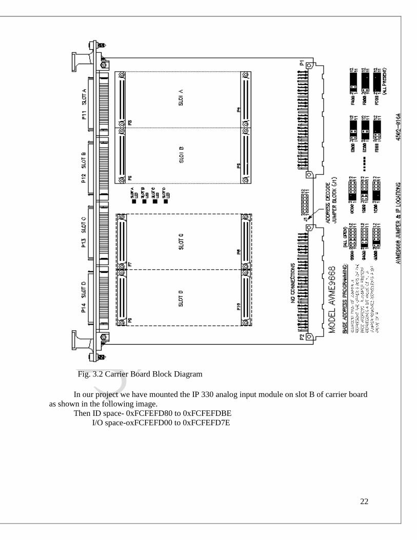
Fig. 3.2 Carrier Board Block Diagram
In our project we have mounted the IP 330 analog input module on slot B of carrier board
as shown in the following image.
Then ID space- 0xFCFEFD80 to 0xFCFEFDBE
I/O space-oxFCFEFD00 to 0xFCFEFD7E
23
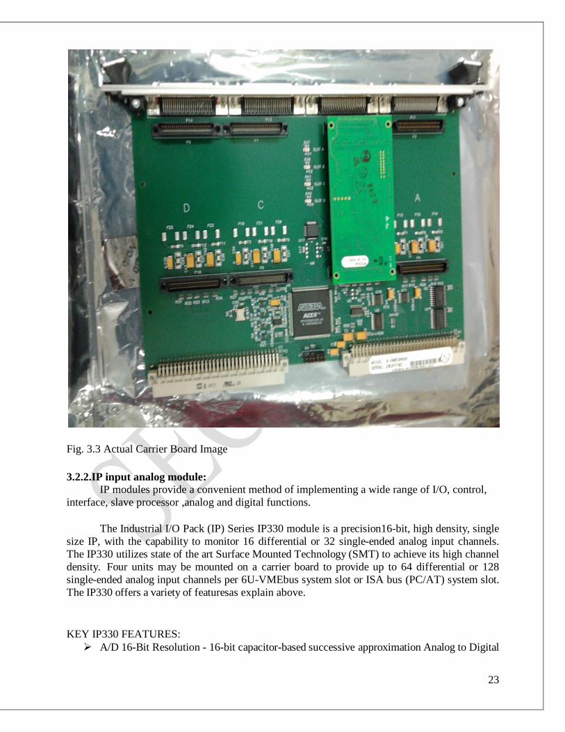
Fig. 3.3 Actual Carrier Board Image
3.2.2.IP input analog module:
IP modules provide a convenient method of implementing a wide range of I/O, control,
interface, slave processor ,analog and digital functions.
The Industrial I/O Pack (IP) Series IP330 module is a precision16-bit, high density, single
size IP, with the capability to monitor 16 differential or 32 single-ended analog input channels.
The IP330 utilizes state of the art Surface Mounted Technology (SMT) to achieve its high channel
density. Four units may be mounted on a carrier board to provide up to 64 differential or 128
single-ended analog input channels per 6U-VMEbus system slot or ISA bus (PC/AT) system slot.
The IP330 offers a variety of featuresas explain above.
KEY IP330 FEATURES:
A/D 16-Bit Resolution - 16-bit capacitor-based successive approximation Analog to Digital

24
Converter (ADC) with integral sample and hold and reference.
High density- Monitors up to 16 differential or 32 single-ended analog inputs (acquisition
mode and channels are selected via programmable control registers).
8usec Conversion Time - A maximum conversion rate of 125KHz is supported. Maximum
recommended conversion rate for specified accuracies is 67KHz.
Individual Channel Mail Box - Two storage buffer registers Are available for each of the 16
differential channels. If configured for 32 single-ended channels, one storage buffer register
is available for each of the 32 channels.
Interrupt Upon Conversion Complete Mode – May be programmed to interrupt upon
completion of conversion for each individual channel or upon completion of conversion of
the group of all scanned channels.
Programmable control of channel scanning- Scan all channels or a subset of the channels
to allow an overall higher sample rate. The channels digitized include all sequential
channels beginning with a specified start-channel value and ending with a specified end-
channel value.
User programmable interval timer- Controls the delay between each channel converted
when Uniform-Continuous or Single Scan modes are selected. If Burst-Continuous is
selected, the Interval Timer controls the delay after a group of channels are converted before
conversion is initiated on the group again. Supports a minimum interval of 8 sec and a
maximum interval of 2.09 seconds.
Uniform Continuous Scanning Mode - All channels selectedfor scanning are continually
digitized in a round robin fashion with the interval between conversions controlled by the
programmed interval timer. The results of each conversion are stored in the channel’s
corresponding mailbox buffer. Scanning is initiated by a software or external trigger.
Scanning is stopped by software control.
Burst Continuous Scanning Mode - All selected input scan channels are sequentially
digitized at a 67KHz conversion rate (15 second conversion time). At the end of a
programmed interval time a new conversion of all channels is re-initiated. The conversion
results are stored in each channel’s mail box buffer.
Uniform Single Cycle Scan Mode - All channels selected for scanning are digitized once
with the idle time between each channel conversion controlled by the programmed interval
timer. The scan is initiated by a software or external trigger.
Burst Single Cycle Scan Mode - All channels selected for scanning are digitized once at a
66.7KHz conversion rate (15 sec/Channel). The scan is initiated by a software or external
trigger.
External Trigger Scan Mode - A single channel is digitized with each external trigger.
25
Successive channels are digitized in sequential order with each new external trigger. This
mode allows synchronization of conversions with external events that are often
asynchronous.
External Trigger Output - The external trigger is assigned to a field I/O line. This external
trigger may be configured as an output signal to provide a means to synchronize other
IP330’s or devices to a single IP330’s on board timer reference.
User Programmable Gain Amplifier - Provides independently software controlled gains (1,
2, 4, and 8V/V) for each of the 16 differential or 32 single-ended channels.
Hardware DIP Switch For Selection of A/D Ranges - Both bipolar 5V, 10V) and
unipolar (0 to 5V and 0 to 10V) ranges are available. Selected range applies to all channels
and can- not be individually selected on a per channel basis.
New Data Register - This register can be polled, to indicatewhen new digitized data is
available in the mail box. A set bit indicates a new digitized data value is available in the
bit’s corresponding mail box register. Register bits are cleared upon read of their
corresponding mail box register or start of a new scan cycle.
User Programmable Data Output Format - Software control provides selection of straight
binary or binary two’s complement data output format.
Hardware Jumpers For Selection of Internal or External Supply - Hardware jumper provide
a means to select internal +/-12 volts or external +/-15 volt supplies. External supplies are
required when using inputs exceeding +/-8.5 volts.
IP module configuration:
For configure IP module, its hardware jumper configuration and analog input hardware
configuration are done and then mounted on carrier board module.
(a)Default Hardware Jumper Configuration:
1. When the board is shipped from the factory, it is configured as follows:
Analog input range is configured for a bipolar input with a 10 volt span (i.e. an ADC input range of
-5 to +5 Volts).
2. Internal +12 and -12 Volt power supplies are used (sourced from P1 connector).
3. The default programmable software control register bits at power-up are described in. The
control registers must be programmed to the desired gain, mode, and channel configuration before
starting ADC analog input acquisition.
Analog Input Range Hardware Jumper Configuration
The ADC input range is programmed via hardware DIP switch. The DIP switch controls the
input voltage span and the selection of unipolar or bipolar input ranges. The configuration of the
DIP switch for the different ranges is shown in the following table. A switch selected as "ON"
would be positioned to the side of the DIP labeled “ON”.

26
Desired ADC
Input Range*
(VDC)
Required
Input Span
(Volts)
Required
Input Type
Switch
Settings ON
Switch
Settings
OFF -5 to +5 10 Bipolar 1,3,4,9 2,5,6,7,8
-10 to +10** 20 Bipolar 2,5,6,9 1,3,4,7,8
0 to +5 5 Unipolar 1,3,5,8 2,4,6,7,9
0 to +10** 10 Unipolar 1,3,4,7 2,5,6,8,9
Analog Input Range Selections/DIP Switch Setting
Table 3.4:- DIP Switch Setting
Power Supply Hardware Jumper Configuration
The selection of internal or external analog power supplies is accomplished via hardware
jumpers J1 and J2. J1 (J2) controls the selection of either the internal +12 (-12) Volt supply
sourced from P1 connector, or the external +15 (-15) Volt supply sourced from the P2 connector.
The configuration of the jumpers for the different supplies is shown in Table3.5.
Power Supply Selections (Pins of J1 and J2)
Power supply
Selection
J1(1&2) J1(2&3) J2(1&2) J2(2&3)
+/-12volt(int.P1) OUT IN OUT IN
+/15volt(ext.P2) IN OUT IN OUT
Table 3.5:- Power supply selection
As shown in following fig.

27
Fig. 3.4 Actual ip330 module
Programming Information
IP IDENTIFICATION PROM
Each IP module contains an identification (ID) information that resides in the ID space per
the IP module specification. This area of memory contains 32 bytes of information at most. Both
fixed and variable information may be present within the ID space. Fixed information includes the
"IPAC" identifier, model number, and manufacturer's identification codes. Variable information
includes unique information required for the module. The IP330 ID information does not contain
any variable (e.g. unique calibration) information.
Hex Offset From ID
PROM Base Address
ASCII Character
Equivalent
Numeric
Value (Hex)
Field Description
01 I 49 All IP's have 'IPAC'
03 P 50
05 A 41
07 C 43
09 A3 Acromag ID Code
Table 3.6:- IP330 ID Space Identification (ID) PROM
I/O SPACE ADDRESS MAP
This board is addressable in the Industrial Pack I/O space to control the acquisition of analog
inputs from the field. As such, three types of information are stored in the I/O space: control,
status, and data.
The I/O space may be as large as 64, 16-bit words (128 bytes) using address lines A1 to A6,

28
but the IP330 uses only a portion of this space. The I/O space address map for the IP330 is shown
in Table 3.7.
Base
Addr+ MSB
D15 D08 LSB
D07 D00 Base
Addr+
00 Control Register 01
02 Timer Prescaler Interrupt Vector 03
04 Conversion Timer 05
06 End Channel Value
Start Channel Value
07
08 New Data Register Channels 0 to 15
09
0A New Data Register Channels 16 to 31
0B
0C Missed Data Register Channels 0 to 15
0D
0E Missed Data Register Channels 16 to 31
0F
10 Not Used Bits15 to Bit 01
Start Convert Bit-0
11
Table 3.7:- I/O space address map for the IP330
3.3 PC with RTOS VxWorks:
Real Time Operating System (RTOS) is a computer system that has timing constraints, that means
an RTOS is partly specified in terms of its ability to make certain calculations or decisions in a timely
manner; that means any system is RTOS if it is Deterministic.
Types of RTOS:-
1.Hard RTOS
2.Soft RTOS
HARD RTOS:-
A system is a hard real time system if failure to respond to an event within a specified
time is considered complete system failure. Complete system failure mean a failure that the
system designers consider unacceptable.
Example- shuttle-craft flight controls

29
SOFT RTOS:-
In soft real time system ,timeliness of response is important but not a matter of life and
death. Designers of a soft rts having witnessed a missed deadline,so syetem failed that one time
.Not a big deal.
Example- remote controlled TV system
VxWorks is RTOS software is using to write programming for communicate real time
applications. For VMEbus there is many RTO software that used for programming. VxWorks
real time operating syatem runs time critical or embedded application.
3.3.1 Facilities of VxWorks Real Time Operating software are:
High-Performance Real-time Kernel Facilities
The VxWorks kernel, wind, includes multitasking with preemptive priority scheduling,
intertask synchronization and communications facilities, interrupt handling support,
watchdog timers, and memory management.
I/O System
VxWorks provides a fast and flexible ANSI C-compatible I/O system
C++ Development Support
In addition to general C++ support including the iostream library and the
standard template library.
Utility Libraries
VxWorks provides an extensive set of utility routines, including interrupt handling,
watchdog timers, message logging, memory allocation, string formatting and scanning,
linear and ring buffer manipulations
Target Agent
The target agent allows a VxWorks application to be remotely debugged using the
Tornado development tools.
Board Support Packages
VxWorks also provides board support packages.
VxWorks Simulator
Multitasking and Intertask Communications are also done by VxWorks.
Brief of tornado VxWorks software:
Tornado Host IDE:
Tornado integrates the various aspects of VxWorks programming into a single
environment for developing and debugging VxWorks applications. The Tornado IDE
allows developers to organize, write, and compile applications on the host system; and
then download, run, and debug them on the target. This section provides more detail on

30
the major features of the IDE.
Tornado Editor
The Tornado source-code editor includes the following features:
Standard text manipulation capabilities.
C and C++ syntax-element color highlighting.
Debugger integration: the editor window tracks code execution.
Compiler integration: the project-management utility links compiler warnings and errors
directly to the affected source in an editor window.
Project Management:
The Tornado project facility simplifies organizing, configuring, and building VxWorks
applications. It includes graphical configuration of the build environment (including compiler
flags), as well as graphical configuration of VxWorks (with dependency and size analysis). The
project facility also provides for basic integration with common configuration management tools
such as ClearCase. The project facility provides mechanisms for:
Organizing the files that make up a project.
Grouping related projects into a workspace.
Customizing and scaling VxWorks.
Adding application initialization routines to VxWorks.
Defining varied sets of build options.
Building applications and VxWorks images.
Downloading application objects to the target.
Compiler:
Tornado includes the GNU compiler for C and C++ programs, as well as a collection of
supporting tools that provide a complete development tool chain:
cpp, the C preprocessor
gcc, the C and C++ compiler
make, the program-building automation tool
ld, the programmable static linker
as, the portable assembler
binary utilities
These tools are supported, commercial versions of the leading-edge GNU tools originally
developed by the Free Software Foundation (FSF). Users of the GNU tools benefit from the
innovative FSF development environment as well as from testing and support by Wind River
Systems.
Among other features, the Tornado project facility provides a GUI for the GNU tools that
is powerful and easy to use.

31
WindSh Command Shell:
WindSh is a host-resident command shell that provides interactive access from the host to
all run-time facilities. The shell provides a simple but powerful capability: it can interpret and
execute almost all C-language expressions. It also supports C++, including "demangling" to
allow developers to refer to symbols in the same form as used by the original C++ source code.
Thus the shell can be used to call run-time system functions, call any application function,
examine and set application variables, create new variables, examine and modify memory, and
even perform general calculations with all C operators.
For even more versatile shell scripting and target control, the Tornado shell includes a
complete Tcl interpreter as well as the C interpreter. The shell also provides the essential
symbolic debugging capabilities, including breakpoints, single-stepping, a symbolic
disassembler, and stack checking.
The shell interpreter maintains a command history and permits command-line editing.
The shell can redirect standard input and standard output, including input and output to the
virtual I/O channels supported by the target agent.
As a convenience, there is some overlap between WindSh and CrossWind, the Tornado
debugger. (Conversely, the CrossWind debugger provides access to all shell built-in commands.)
From the shell, you can perform the following debugging activities:
Display system and task status.
Generate a symbolic disassembly of any loaded module.
Set breakpoints and single-step specific tasks, even in shared code.
Set breakpoints and single-step the system as a whole, even in interrupt service
routines.
As with all Tornado tools, these facilities provide symbolic references wherever possible,
using the symbol table managed by the target server.

32
Fig 3.5:- TORNADO Shell Image
CrossWind Debugger:
The remote source-level debugger, CrossWind, is an extended version of the GNU
source-level debugger (GDB). The most visible extension to GDB is a straightforward
graphical interface. CrossWind also includes a comprehensive Tcl scripting interface that
allows you to create sophisticated macros or extensions for your own debugging
requirements. For maximum flexibility, the debugger console window synthesizes both
the GDB command-line interface and the facilities of WindSh, the Tornado shell.
From your development host, you can use CrossWind to do the following:
Spawn and debug tasks on the target system.
Attach to already-running tasks, whether spawned from your application, from a
shell, or from the debugger itself.
33
Use breakpoints and other debugging features at either the application level or the
system level.
View your application code as C or C++ source, as assembly-level code, or in a
mixed mode that shows both.
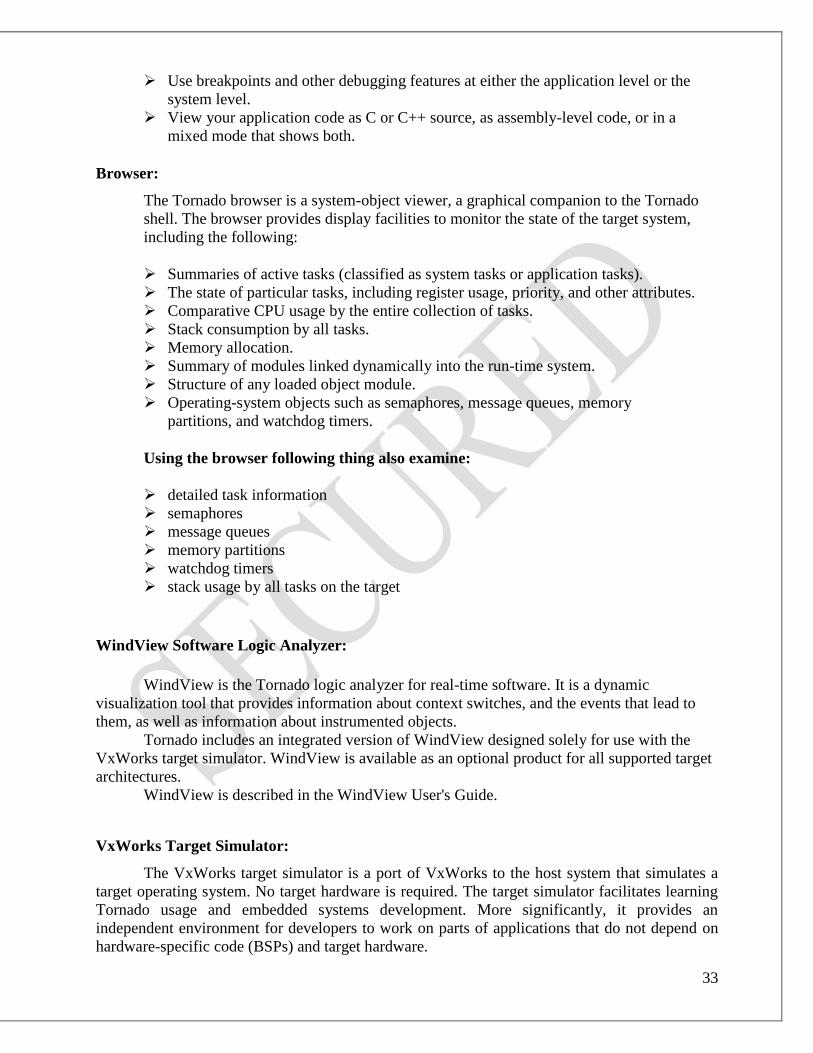
Browser:
The Tornado browser is a system-object viewer, a graphical companion to the Tornado
shell. The browser provides display facilities to monitor the state of the target system,
including the following:
Summaries of active tasks (classified as system tasks or application tasks).
The state of particular tasks, including register usage, priority, and other attributes.
Comparative CPU usage by the entire collection of tasks.
Stack consumption by all tasks.
Memory allocation.
Summary of modules linked dynamically into the run-time system.
Structure of any loaded object module.
Operating-system objects such as semaphores, message queues, memory
partitions, and watchdog timers.
Using the browser following thing also examine:
detailed task information
semaphores
message queues
memory partitions
watchdog timers
stack usage by all tasks on the target
WindView Software Logic Analyzer:
WindView is the Tornado logic analyzer for real-time software. It is a dynamic
visualization tool that provides information about context switches, and the events that lead to
them, as well as information about instrumented objects.
Tornado includes an integrated version of WindView designed solely for use with the
VxWorks target simulator. WindView is available as an optional product for all supported target
architectures.
WindView is described in the WindView User's Guide.
VxWorks Target Simulator:
The VxWorks target simulator is a port of VxWorks to the host system that simulates a
target operating system. No target hardware is required. The target simulator facilitates learning
Tornado usage and embedded systems development. More significantly, it provides an
independent environment for developers to work on parts of applications that do not depend on
hardware-specific code (BSPs) and target hardware.
34
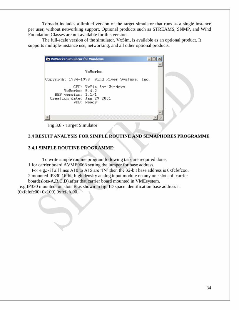
Tornado includes a limited version of the target simulator that runs as a single instance
per user, without networking support. Optional products such as STREAMS, SNMP, and Wind
Foundation Classes are not available for this version.
The full-scale version of the simulator, VxSim, is available as an optional product. It
supports multiple-instance use, networking, and all other optional products.
Fig 3.6:- Target Simulator
3.4 RESUIT ANALYSIS FOR SIMPLE ROUTINE AND SEMAPHORES PROGRAMME
3.4.1 SIMPLE ROUTINE PROGRAMME:
To write simple routine program following task are required done:
1.for carrier board AVME9668 setting the jumper for base address.
For e.g.:- if all lines A10 to A15 are ‘IN’ then the 32-bit base address is 0xfcfefcoo.
2.mounted IP330 16-bit high density analog input module on any one slots of carrier
board(slots-A,B,C,D).after that carrier board mounted in VMEsystem.
e.g.IP330 mounted on slots B as shown in fig. ID space identification base address is
(0xfcfefc00+0x100) 0xfcfefd00.

35
Fig. 3.7:- Implementation of ip330 on carrier board
3. Then write sample programme as shown in fig. 3.8.

36
Fig. 3.8 sample programme

37
4.set the analog input +/-5V. connect it as shown in fig. 3.9.
Fig. 3.9:- Analog Input

38
5.check digital output codes on simulator by running the programme. The output is shown.
Fig. 3.10 Output of sample programme on simulator
Procedure:
1.Copy the source code in the example and compile it.
2.Load the object file onto the target machine.
3.Run the example by executing the main routine (binary,etc.)of the example on WindSh
terminal.
Note: Make sure about redirected I/O,otherwise we won’t see the results of the printf commands. 3.4.2 What is semaphore?
VxWorks semaphores are highly optimized and provide the fastest intertask communication
mechanism in VxWorks. Semaphore is a tool that allows multitasking applications in
VxWorks. All tasks in VxWorks exist in a single linear address space. Using semaphores, the
exchange of data is simplified by shared address space.

39
Types of semaphores:
There are three types of semaphores.
1. Binary
2. Mutual exclusion
3. Counting
Binary semaphores: VxWorks binary semaphores are the most versatile & fastest, efficient and conceptually
simple type of semaphore. They can be used to: (1) control mutually exclusive access to shared
devices or data structures, or (2) synchronize multiple tasks and interrupt-level processes. Binary
semaphores form the foundation of numerous VxWorks facilities. A binary semaphore can be
viewed as a cell in memory whose contents are in one of two states, full or empty.
Mutual exclusion semaphores:
The mutual-exclusion semaphore is a specialized binary semaphore designed to
address issues inherent in mutual exclusion, including priority inversion, deletion
safety, and recursive access to resources. The fundamental behavior of the mutual-exclusion
semaphore is identical to the binary semaphore, with the following exceptions:
■ It can be used only for mutual exclusion.
■ It can be given only by the task that took it.
Counting semaphores:
Counting semaphores are another means to implement task synchronization and mutual
exclusion. The counting semaphore works like the binary semaphore except that it keeps track of
the number of times a semaphore is given. Every time a semaphore is given, the count is
incremented; every time a semaphore is taken, the count is decremented. When the count reaches
zero, a task that tries to take the semaphore is blocked. As with the binary semaphore, if a
semaphore is given and a task is blocked, it becomes unblocked. However, unlike the binary
semaphore, if a semaphore is given and no tasks are blocked, then the count is incremented. This
means that a semaphore that is given twice can be taken twice without blocking
CALL ROUTINE DESCRIPTION
semBCreate(SEM_Q_PRIORITY,
SEM_FULL)
Allocates and initializes a binary semaphore.
SemMCreate(SEM_Q_PRIORITY
| SEM_INVERSION_SAFE)
Allocates and initializes a mutual-exclusion semaphore.
semCCreate(SEM_Q_PRIORITY,
__________)
Allocates and initializes a counting semaphore.
semDelete(semId) Terminates and frees a semaphore.

40
semTake(semId,
WAIT_FOREVER)
Takes a binary, mutual-exclusion, or counting semaphore or
a read/write semaphore in write mode. A semTake() with
WAIT_FOREVER means wait indefinitely & if it’s with
NO_WAIT, it means no wait at all.
semGive(semId) Gives a binary, mutual -exclusion, or counting semaphore.
semFlush(semId) Unblocks all tasks that are waiting for a semaphore.
Table 3.8:- Call Routine Description
We are using semBCreate(SEM_Q_PRIORITY, SEM_FULL) as binary semaphores are the
most versatile & fastest, efficient and conceptually simple type of semaphore.
The programme with binary semaphores as follows:
#include <vxWorks.h>
#include <stdio.h>
#include <taskLib.h>
#include <logLib.h>
#include <semLib.h>
//#include <gecg28ip330.h>
#define ip330_base 0xfcfefd00
void appy_test(void);
void gecg28(int);
SEM_ID semId;
volatile unsigned short* ip330_ct=(unsigned short*)0xfcfefd00;
volatile char* ip330_en=(char*)0xfcfefd06;
volatile char* ip330_st=(char*)0xfcfefd07;
volatile char* ip330_tp=(char*)0xfcfefd02;
volatile unsigned short* ip330_ctb=(unsigned short*)0xfcfefd04;
volatile char* ip330_scb=(char*)0xfcfefd11;
volatile unsigned short* ch1=(unsigned short*)0xfcfefd40;
void appy_test(void)
{
int tid, i=5;
semId=semBCreate(SEM_Q_FIFO, SEM_EMPTY);
tid=taskSpawn("gecg",123,0,5000,(FUNCPTR)gecg28,i,0,0,0,0,0,0,0,0,0);
}
void gecg28(int d)
{
semTake(semId, WAIT_FOREVER);
*ip330_ct=0x0906;
*ip330_en=0x01;
*ip330_st=0x00;
*ip330_tp=0x50;
*ip330_ctb=0x18;
taskDelay(5);
*ip330_scb=0x01;
taskDelay(5);
printf("ip330 channel 1 value =%x %d \n",*ch1, d);

41
//logMsg("ip330 channel 1 value = %x %x\n",*ch1,i,0,0,0,0);
}
Fig. 3.11 Semaphore program

42
Fig. 3.12 Semaphore program output
Procedure:
1.Copy the source code in the example and compile it.
2.Load the object file onto the target machine.
3.Run the example by executing the main routine (binary,etc.)of the example on WindSh
terminal.
Note: Make sure about redirected I/O,otherwise we won’t see the results of the printf commands.
ISR (Interrupt Service Routine)
What is ISR?
ISR (Interrupt Service Routine) is a tool used for interrupting the sequence of the program.
Interrupts allow devices to notify the CPU that some event has occurred.
In VxWorks, C functions can be connected to any interrupt by intConnect( ).
ISRs are restricted to be used in Some VxWorks functions such as semTake( ), malloc( ), printf(
) etc. because these call functions may cause blocking and thus creation & deletion functions are
restricted.
To print out messages from an ISR, function logMsg or other functions provided by the library
logLib are used.

43
To improve cooperation between VxWorks' ISRs and tasks, the best
mechanism is semaphore semGive( ).
CALL ROUTINE for ISR
intConnect(INUM_TO_IVEC(INTERRUPT_LEVEL),(VOIDFUNCPTR)interruptHandler,i)
to write interrupt programme following registers are required to configure:-
(1) Carrier Board Status Register (CBSR)
(2) Interrupt Vector Register (IVR)
(3) Interrupt Level Register (ILR)
(4) Interrupt Clear Register (ICR)
(5) Interrupt Enable Register (IER)
(1) Carrier Board Status Register (CBSR) - (Read/Write, Base + C1H)
The Carrier Board Status Register reflects and controls functions globally on the carrier board.
MSB D7 D6 D5 D4 D3 D2 D1 LSB D0
ACE
(Auto
Clear
Interrupt
Enable)
Not Used Not Used Soft
Reset
GIE
(Global
Interrupt
Enable)
GIP
(Global
Interrupt
Pending)
Not Used Not Used
Where;
Bit 7 Writing a ‘1’ to this bit will enable automatic clear of pending interrupts on the
carrier. An interrupt will only remain set as pending on the carrier if its
corresponding IP module has an active interrupt request.
Bits 6,5 Not used – equal ‘0’ if read
Bit 4 Writing a ‘1’ to this bit causes a software reset. Writing a ‘0’ to this bit for
hardware interrupt.
Bit 3 writing a ‘1’ to this bit enables interrupts to be serviced, provided the interrupts
are supported and configured. Set this bit to ‘0’ disables the interrupts.
Bit 2 this bit will be ‘1’ when there is an interrupt pending. This bit will be ‘0’ when no
interrupt is pending.
Bits 1,0 Not used – equal ‘0’ if read
(2) Interrupt Vector Register (IVR) – (Read/Write, Base + 03H)
The Vector Register can be written with an 8-bit interrupt vector. This vector is provided to the
carrier and system bus upon an active INTSEL* cycle. Read or writing to this register is possible
via 16-bit or 8-bit data transfers. 16-bit data transfers will implement simultaneous access the
Interrupt Vector and Timer Prescaler registers. The register contents are cleared upon reset.

44
Fig. 3.13 Program of Interrupt Service Routine

45

46
Fig. 3.14 output of ISR program
Procedure:
1.Copy the source code in the example and compile it.
2.Load the object file onto the target machine.
3.Run the example by executing the main routine (binary,etc.)of the example on WindSh
terminal.
Note: Make sure about redirected I/O,otherwise we won’t see the results of the printf commands.
Multi-Tasking
Multi tasking in VxWORKS:
Multi tasking is a process in which a set of independent tasks are performed.
In the VxWorks multitasking is performed by using
either interrupt or priority- based task scheduling.
A muilitask's context includes:
a thread of execution, that is, the task's program counter
the CPU registers and floating-point registers if necessary
a stack of dynamic variables and return addresses of function calls
I/O assignments for standard input, output, error
a delay timer
a timeslice timer

47
kernel control structures
signal handlers
debugging and performance monitoring values
The routine taskSpawn creates the new task context, which includes allocating and setting up
the task environment.
The new task begins at the entry to the specified routine.
Syntax
id = taskSpawn(name,priority,options,stacksize,function, arg1,..,arg10);
programme of multi-tasking:
#include <vxWorks.h>
#include <stdio.h>
#include <taskLib.h>
#include <logLib.h>
#include <semLib.h>
//#include <gecg28ip330.h>
#define ip330_base 0xfcfefd00
#define ITERATIONS 10
void gecg28(void);
volatile unsigned short* ip330_ct=(unsigned short*)0xfcfefd00;
volatile char* ip330_en=(char*)0xfcfefd06;
volatile char* ip330_st=(char*)0xfcfefd07;
volatile char* ip330_tp=(char*)0xfcfefd02;
volatile unsigned short* ip330_ctb=(unsigned short*)0xfcfefd04;
volatile char* ip330_scb=(char*)0xfcfefd11;
volatile unsigned short* ch1=(unsigned short*)0xfcfefd40;
spawn_ten() /* Subroutine to perform the spawning */
{
int i, taskId;
for(i=0; i < ITERATIONS; i++) /* Creates ten tasks */
taskId = taskSpawn("gecgprint",90,0x100,2000,print,0,0,0,0,0,0,0,0,0,0);
}
void gecg28(void) /* Subroutine to be spawned */
{
printf("Hello, I am task %d\n",taskIdSelf()); /* Print task Id */
}
48
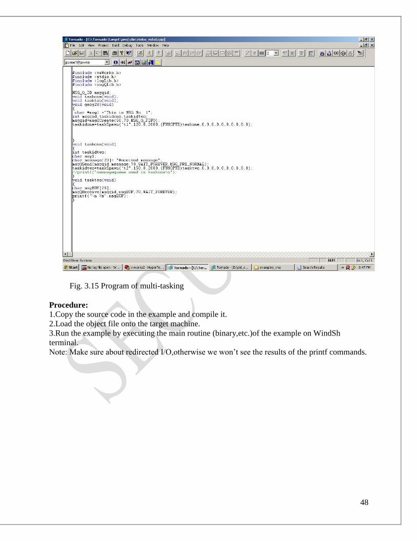
Fig. 3.15 Program of multi-tasking
Procedure:
1.Copy the source code in the example and compile it.
2.Load the object file onto the target machine.
3.Run the example by executing the main routine (binary,etc.)of the example on WindSh
terminal.
Note: Make sure about redirected I/O,otherwise we won’t see the results of the printf commands.

49
CHAPTER 4
DP CONFIGURATION
DP CONFIGURATION:-
Steps of Installation:
1. Connect the hardlock to the parallel port. The hardlock tested periodically whole using the DP
Configurator.
2. Start the “setup.exe” program on the delivery disk with Program Manager by selecting the
menus “File” , “Execute” or with File Manager by simply double –clicking the file “setup.exe”.
3. Enter the destination drive and directory in the dialog presented to you. The directory will be
created if necessary.
4. The set-up program adds a program group “DP Configurator ” to the Program Manager or puts
entries into the group PROFIBUS of the start menu. Start the Configurator by (double)clicking
its icon in this group.
5. The delivery supplies the DDB files of the Softing master PROFIBUS controller cards and a
slave. To add your own DDB files(master or slaves), import them first with the menu “DDB”,
“Import” before opening a new or existing project.
6. For online configuration of remote master, the DP Configurator will look for the papi_l.dll.
This DLL is part of the PROFIBUS/DP DMK package and may not be part of the DP
Configurator. Enter the directory hosting this DLL either in your PATH environment variable or
copy the papi_l DLL to the application directory of the DP Configurator.
Configuration of DP Applications
In a PROFIBUS DP network, a DP Master (class1) controls and communicates with several
assigned slaves. The master needs a Master Parameter Set to start communications with the
slaves, to send parameterization data to slaves on request, to poll the assigned slave devices and
to prevent the I/O data in the communication area between a master application and the protocol
stack.
DP Master Parameter Set
A Master Parameter Set describes the network as seen by a single master. The parameter set
decides the bus peremeters and the configuration of all slaves assigned to this master. In multi-
master environment, every master has its own Master Parameter Set.
The Master Parameter Set consists of:
- one Bus Parameter Set
- max. 125 DP Slave Parameter Sets

50
Fig. 4.1:- DP Master Parameter Set
The DP Bus Parameter Set consists of the standard FDL operational parameters and some new
DP specific extentions.
DP Slave Parameter Sets
The DP Slave Parameter Sets are used to declare the features of each DP Slave and to define the
whole DP application. It is the most important data base for the user.
Fig. 4.2:- DP Slave Parameter Set
The Configurator has specific support for AAT-MODE “Compact”.
Features:
A single Master Parameter Set configuration is called a configuration project. Its data is
transferred to the DP master when starting up the master application.
The DP Configurator software offers the following features:
- Import third party provided device descriptions as DDB files (referred as GSD),

51
- Create and edit configuration projects by adding ,changing and deleting device for master
and slaves,
- Configure bus parameters,
- Configure compact and modular slaves including extended user parameters,
- Assign addresses to devices and slaves groups, change operation modes , edit watchdog
timeouts for slaves,
- Save a Parameter Set as binary file for later use by a master application(i.e. Softing DDE-
Server),
- Directly download the Master Parameter Set to a remote DP master (via PROFIBUS).
General Behavior:
The User Interface of the DP Configure behaves like a standard Windows MDI-
Application(Multiple Document Interface). The user has access to a menu, a toolbar and an area
where all child documents will be displayed.
Fig. 4.3:- Tool-Bar and Menus
Whenever a function is not applicationin the current context (e.g. Delete Slave when no slaves is
selected), the corresponding button is disabled.
Project
The Project menu presents all functions to create new projects and load previous projects and to
exit the DP Configurator. A project in this context is a configuration of a Master Parameter Set
for one master and all of its assigned slaves.
More on 12th
DDB
The Device DataBase (DDB) contains descriptions for master and slave devices available for
configuration projects. Add new device descriptions by importing standardized DDB files with
the menu “DDB”, “Import”.
Import
To change the device database , save close all projects first. Select the menu “DDB”, “Import”.

52
Fig. 4.4:- Database Import Dialogue
In order to remove a device from the database, select the device to be deleted and either double –
click the mouse or click the button Remove.
In order to import a device (its DDB file),click on the Add button. The following dialog appears:
Fig. 4.5:- Selecting Files for Import
Select drive and directory with the DDB files to import into the DP Configurator’s database.
Several DDB-files may be imported at once by marking them all and pressing ok.
The results of an import operation are logged into a file named gsd_pars.log in the database
directory. If a warning or an error appeared during the parsing of the files , a message box
informs about results being written into the logfile.
Change Database
A device is identified by its description file, which always has the name dp_konf.gls. By
choosing a different dp_konf.gls, the database is changed. The ini-file is not changed by this
function, so the list of projects in the Project-menu refer to a different database- this can cause
errors.

53
Download
This version supports two download methods: generation of a local configuration file and online
access with a remote download.
Remote Download transfers the current configuration data to a remote master(class1) with a
local master. This enables the remote master to access the configured slaves. Never download a
new configuration while the remote master is actively controlling any process.
Download to binary file transfers the current configuration in binary form to a MSDOS file.
This file may be downloaded by another DP master application, Softing’s DPDDE Seaver. The
configurator presents a dialog to select the desired path and name for the binary file. By default,
the dialog proposes the project path and filename,replacing the extension by “bin”.
Options
Basic Mode /Advanced Mode
PC Interface
Busparameter Master Class 2
Busparameter Template
Setting
Basic Mode /Advanced Mode:
In Advanced Mode , all bus parameters in master and slave are accessible. For a better protection
against unintentional change of critical parameters,the mode can be set to Basic Mode. In Basic
Mode , some parameters in the respective dialogs are disabled.
The current mode can be seen on the status-bar : BAS or ADV indicate
the current mode.
The operation mode can only be changed, when no project is open. To change the mode, close all
projects first.
PC Interface:
Select this menu to change the setting for the installed PROFIBUS DP controller hardware and
to set the bus parameters when the DP Configurator operates as master class 2.

54
Fig. 4.6:- Configuration of local PROFIBUS Interface
This dialog lets the user select one of the supported PROFIBUS controllers. Currently the
following controllers are supported:
- PROFIboard
- PROFIcard
Hardware Addresses (PROFIboard only, on 16 –Bit PAPI):
I/O Base Address Port I/O Address
The value given here must match the
setting of the I/O Base Address on the
PROFIBUS controller card
Than ensure that this address is not in
use by any other hardware device in
our system
Dual Ported RAM Address Hardware base address of 16 KB dual
ported RAM
The specified segment must be excluded from system usage (DOS and Windows)
Hardware Set-up Files (PROFIcard only , on 16 Bit-PAPI):
Loadcard INI Path and name of INI file with settings
of the installed PROFIcard.
This file is located in our CARDINST
directory.
Windows 95,98 may require, Window NT and 2K always require, that PROFIboard has to be
selected even if a PROFIcard is installed, depending on the installed drivers.

55
BUSparameter Master Class 2
Fig. 4.7:- Parameters for local master class 2
The Busparameter Master Class 2 dialog lets we edit the settings to use as master class2. the DP
Configurator uses the setting as configuration master to download to a remote master(master
class 1).
Than select an appropriate station address for master class 2 and the desired buadrate.
The pushbutton Edit.. brings up a dialog to edit bus communication parameters in detail. The
dialog resembles the one from “BUS PARAMETERS”, except that the entries Delta Ttr and
Watchdog/Ttr are constantly disabled.
Busparameter Template:
The template master defines station- and bus parameters to use when a master is added to a
project. The settings are saved in the application’s INI file.
Fig. 4.8:- Template Parameters

56
The first dialog defines the template station parameters. Enter the timings as ms ,or us
respectively.
Select a template buadrate and busparameters by activating the pushbutton “Edit
Busparameters..”. The dialog resembles the one from “Bus Parameters”, except that all entries
are enabled irrespective of the modes Basic/Advanced.
Settings:
Fig. 4.9:- Settings Dialog
The settings are saved into the ini-File and thus do not refer to a certain project, they are active
for all projects.
Strict HSA-Checking influences the functionality of Check Config and Auto Config with respect
to the HSA(Highest Station Address). If enabled, HSA is tested against / set to the highest
address of all stations, if disabled, it is tested / set to the highest master address.
Compatible CNF-Output assures that the file-output is compatible to earlier versions of the DP-
Configurator. Do not use this option unless necessary, as some data from several dialogs get lost
after closing the project.
Offset Inputs and Offset Outputs affect the address assignment table: DP-Configurator generates
address information for all inputs from Offset Inputs on, Offset Output is the start address of the
output page. The generated binary files can be used in AAT-Modes Array, Compact and IO-
Blocks. In AAT-Modes Array and IO-Blocks, the offset will be ignored by the master card! Do
not use the calculated offsets in an application except from AAT-Mode Compact.
View:
The menu “View” lets you show or hide the toolbar and the status bar.
Window:
The menu “Window” lets you arrange the project windows.
Project Window:
A project window hosts a single configuration project. The titlebar shows the file name of the
configuration file. The project window is split into two lists:
The lists to the left are the actual configuration project with the master and its associated
ant configured slaves.
The lists to the right presents us the imported master and slave device descriptions in the
device database as selection list.

57
Fig. 4.10:- Project Pane
First, pick a master for our project by selecting a master device description in the master
selection list with the mouse or with the tab and cursor keys. Either double click the line in the
list box or use the corresponding button from the toolbar or press <Enter>. The DP Configurator
presents a “DP Master Configuration” dialog.
Later on, the master’s parameters can be changed by selecting the actual master in configuration
list on the left of the project window. Either double click the line in the list box or box or use the
corresponding button from the toolbar.
Add a slave to our project by selecting and activating a slave device description in the
slave selection list. The DP Configurator presents a “DP Slave Configuration” dialog. Repeat
this step for every slave station in the project.
Change the parameters of a slave by activating the actual slave in the configuration list.
Delete a slave from the project by selecting the slave and then use the Cut-Button from
the toolbar.
Duplicate a slave in the project by selecting the slave and then use the Copy-Button from
the toolbar. Change the slave’s address immediately, as the copy is exact and duplicate addresses
are not allowed.
58
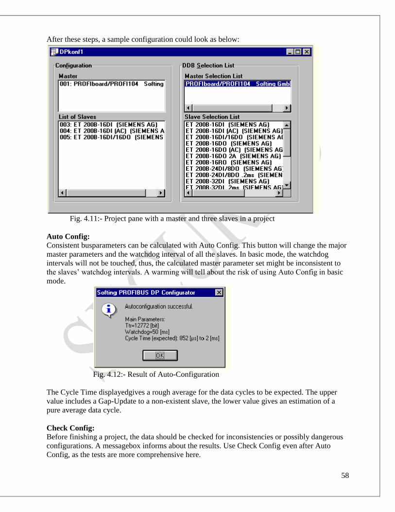
After these steps, a sample configuration could look as below:
Fig. 4.11:- Project pane with a master and three slaves in a project
Auto Config:
Consistent busparameters can be calculated with Auto Config. This button will change the major
master parameters and the watchdog interval of all the slaves. In basic mode, the watchdog
intervals will not be touched, thus, the calculated master parameter set might be inconsistent to
the slaves’ watchdog intervals. A warming will tell about the risk of using Auto Config in basic
mode.
Fig. 4.12:- Result of Auto-Configuration
The Cycle Time displayedgives a rough average for the data cycles to be expected. The upper
value includes a Gap-Update to a non-existent slave, the lower value gives an estimation of a
pure average data cycle.
Check Config:
Before finishing a project, the data should be checked for inconsistencies or possibly dangerous
configurations. A messagebox informs about the results. Use Check Config even after Auto
Config, as the tests are more comprehensive here.

59
Groups:
Fig. 4.13:- Association of slave to group
Groups gives an overview of the assignment of slaves to goups. This assignment can be changed
by editing the slave in the “Slave Configuration Dilog”; “Tab Setting”. Each slave in the project
has two markers, indicating whether Sync(‘S’) or Freeze(‘F’) are activated. If the corresponding
feature is not activated, this is noted by an ‘n’.
Usually , one Group should be consistent(i.e. all slaves support the same features within one
group.)

60
DP Master Configuration Dialog:
Fig. 4.14:- Master Parameters
This dialog is divided into three frames:
The info frame displays the vendor information of the DP Master device: vendor name, device
name, device revision and ident number.
The parameters frame:
Station Address Enter the master’s station address in a range of 0 to 126. The
dialog proposes a default address 1.
Min. Slave Interval This time gives a lower bound for the DP-cycles and should be as
small as possible, but no smaller than the slowest slave allows.
Poll Timeout Timeout for Master-Master operations. The dialog suggests the
Min_Poll_Timeout value declared in the master DDB.
Data Control Time Timeout for data update for all slaves.
Autoclear Enables fallback from operation mode ‘operate’ to ‘clear’, if
timeout ‘Data Control Time’ is violated by atleast one slave.

61
Bus Parameters:
Fig. 4.15:- Net Parameters
When selecting a baudrate, the values in the edit fields for the bus parameters are updated to
present a reasonable default set. All timing values are in multiples of the bit time tbit, except
Watchdog/Ttr, which is in Percent.
In basic configuration mode, some fields are disabled and cannot be edited.
Delta Ttr represents the time needed for further PROFIBUS-Masters, e.g. if online configuration
with a DP-Master Class 2 is used, Delta Ttr has to be non-zero.
Slave Configuration Dialog:
This dialog consists of four property sheets which are accessible vai the tabs below the dialog’s
toolbar.
For modular slaves, the user must configure atleast one slot to successfully complete this dialog.

62
Tab: Basic
Fig. 4.16:- Basic Slave Parameters
The first field in the subdialog Basic displays the general slave descriptions as supplied by the
slave vendor: vendor name, device name, ident number, revision.
The second field sums up the slave’s I/O-length over all modules and either displays the name of
the first virtual module in a compact slave or identifies a slave as Modular Slave.
In the third field, the user provides:
Station Address Either the slave’s station address in a range of 0 to 126
The dialog proposes the next free station address.
Active If this checkbox is not marked, the slave is inactive, i.e. the station is not
included in the update cycle when the master starts running in mode
Clear/Operate
63
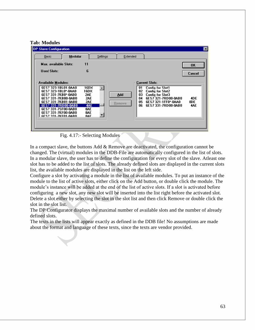
Tab: Modules
Fig. 4.17:- Selecting Modules
In a compact slave, the buttons Add & Remove are deactivated, the configuration cannot be
changed. The (virtual) modules in the DDB-File are automatically configured in the list of slots.
In a modular slave, the user has to define the configuration for every slot of the slave. Atleast one
slot has to be added to the list of slots. The already defined slots are displayed in the current slots
list, the available modules are displayed in the list on the left side.
Configure a slot by activating a module in the list of available modules. To put an instance of the
module to the list of active slots, either click on the Add button, or double click the module. The
module’s instance will be added at the end of the list of active slots. If a slot is activated before
configuring a new slot, any new slot will be inserted into the list right before the activated slot.
Delete a slot either by selecting the slot in the slot list and then click Remove or double click the
slot in the slot list.
The DP Configurator displays the maximal number of available slots and the number of already
defined slots.
The texts in the lists will appear exactly as defined in the DDB file! No assumptions are made
about the format and language of these texts, since the texts are vendor provided.

64
Tab: Settings
Fig. 4.18:- Advanced set-up of a slave
The subdialog Settings lets the user supply more detailed slave configuration data.
In the first frame Operation Mode, the user provides:
Min. Station Delay Responder The value states the station delay time (slave internal
processing time) of this station. This time is declared in the
slave DDB as min TSDR
Sync Req. Freeze Req If the slave supports synchronize and freeze requests, these
checkboxes are enabled. Check the boxes to activate the
requests.
Fail Save If the slave supports Sail-Save (data transfer of telegrams
with no data instead of telegrams with zeros in operation
mode clear), this checkbox is enabled. Check the box to
activate Fail-Save-Support in Master and Slave.
If the slave requires Fail-Save operation, the box is marked
and disabled, so operation without Fail-Save is not
possible.
Watchdog Time If the slave supports its own watchdog timer, this check
box timer is enabled. Check the box and edit a timeout to
activate the watchdog.
This watchdog fires if the slave will not be polled by the
master before the timeout expires. The slave will clear all
outputs when the watchdog fires.

65
In the second frame Groups, the user defines the slave’s association to any of up to eight groups.
An overview of all slaves in all eight groups can be accessed from the project window by
activating the “Groups” pushbutton.
In the third frame User Prm Data, the User Parameter Data can be entered. By default the DDB
data are shown and can be modified.
Tab:Extended:
Fig. 4.19:- Extended User Parameters
Extended user parameters allow a symbolic manipulation of user parameters. The tab Extended
is enabled if the DDB-File contains the necessary information.
Extended user parameters are set for each module. By activating one module in the list of
available slots, the list of available parameters is initialized. By activating one entry in the list of
user parameters, the current value of this parameter is displayed. Select a symbolic value or enter
a number within the numeric range. The list of available slots also contains additionally a virtual
slot Device Data. Usually, its parameters refer to the whole slave.
Changes done in this dialog can be monitored in the dialog Setting, too. This redundant way of
changing user parameters is necessary as not all slaves have DDB-Files with symbolic
representation of user parameters.
Automatic Import of Slaves:
Users who have a tool which generates XPT-Output, can automatically integrate complete
projects.
Invoking the automatic import of Slaves:
The Edit Menu has an additional entry “Import Slaves”.

66
Fig. 4.20:- Edit menu with new import “import slaves”
The DP-Configurator asks for an XPT-File, which has tocontain a master description and one or
more slave descriptions. The master’s address has to match the address of the master in the
current project. The slaves found in the file replace the slaves of the current project.
Errors during import:
Whenever an error is detected, a message box tells about the fact, that the import was
incomplete.
Fig. 4.21:- Error message when importing slave
The database directory contains a file named xpt_parts.log, which is non empty in case an error
is detected. The following major error conditions are tested sequentially.
Error Behaviour
Illegal Syntax of the XPT-File, e.g. missing
keyword or missing separator
The import is cancelled, the current project
is not touched.
Master Address in the XPT-File does not
match the address configured
The import is cancelled, the current project
is not touched.
The requested GSD-File was not found in
the database
The slave is not configured into the project.
The requested slave contains modules,
which are not in the GSD-File
The slave is not configured into the project.
Whenever a syntax error is detected, the logging file contains the keyword, which came
unexpected, and the line, where the error was found. A missing keyword is therefore indicated as

67
an unexpected keyword, e.g., if the keyword ENDSLAVE is missing, the following
BEGINSLAVE is marked as unexpected.
Project description of DP configuration:-
DP configuration of VME interface card as master and 1 slave CBP2 Module
DP Master Configuration:
This is done by using SOFTING software. The steps are as follow:
DPConfigurator → Project → New Project
clicking on New Project, the above window will be shown. From Master Selection List, select
PROFIboard/PROFI104(Softing GmbH). So, another window will be shown as follows.
By default, the Station Address is “1”. Here, we will change it to “2” because VME system is
already having a master SBSVG4.
We can change only the Station Address. The other parameters (Min. Slave Interval, Poll
Timeout & Data Control Time) can’t be changed from their default values.
In Busparameters, we select the Baudrate 1.5 MBaud, which will be expanded up to 12MBaud.
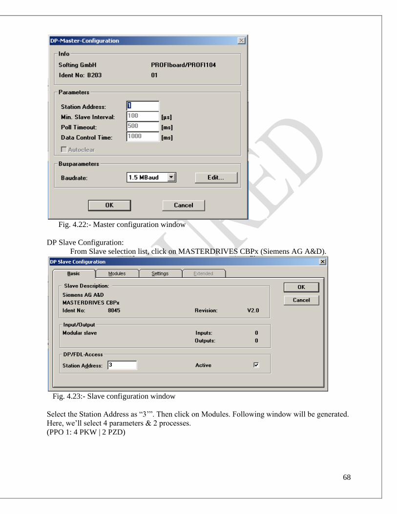
68
Fig. 4.22:- Master configuration window
DP Slave Configuration:
From Slave selection list, click on MASTERDRIVES CBPx (Siemens AG A&D).
Fig. 4.23:- Slave configuration window
Select the Station Address as “3’”. Then click on Modules. Following window will be generated.
Here, we’ll select 4 parameters & 2 processes.
(PPO 1: 4 PKW | 2 PZD)

69
Then click on Settings. The following window will be displayed.
GSD File:
This document describes the definition of the GSD file format for DP. In order to achieve a
simple plug & play configuration for PROFIBUS , electronic device datasheets (GSD files) are
defined for communication features of the devices. These GSD files are a Human readable
ASCII text files. Keywords are specified as mandatory or optional with the corresponding data-
type and their border values to support the configuration of PROFIBUS devices.
Based on the defined file format it is possible to realize vender independent configuration tool
for PROFIBUS systems. The configuration uses GSD files for testing the data. These were
entered regarding limits and validity related to the performance of the individual device.
The manufacturer of a device is responsible for the functionality and the quality of its GSD file.
The device certification procedure is requesting either a standard GSD file based on a
PROFIBUS profile or a device specific GSD file.
For different slaves, there are different GSD files. If the GSD file is not provided for a slave, we
can also create its GSD file by providing details in Slave Configuration → User Prm Data.

70
GSD file of CBP2 Module:
; (c) 1997 Siemens AG ASI 1
;
; Profibus-DP Geraetestammdatei für MASTERDRIVES Baugruppen CBP und CBP2
; MLFB: CBP = 6SE7090-0xx84-0FF0 ; CBP2 = 6SE7090-0xx84-0FF5
;
; Autor: Heinz Kerpen ( H.K. )
; Erstellungsdatum: 13.03.97
; Aenderungen: H.K. 22.05.97 S7-Typkennung fuer Slot 5 von 0x23 auf 0xA3
; H.K. 06.06.97 Min-Slave-Intervall=1,3 ms
; S7-Typkennungen -> Kennungsbytes , Bitmap-Device
; H.K. 01.07.97 Abgleich GSD-Datei mit Typdateien ( V 1.0 )
; H.K. 29.10.97 Min_Slave_Int. von 13-->5 / User_Prm_Data_Len = 0 /
; d.h. Abgleich mit SSC-Vorschlägen
; H.K. 30.10.97 Slave_Family=1@TdF@SIMOVERT
; Revision 1.1: H.K. 14.08.98 24V_Pins=0 ( vorher=2 ) ; Software V1.2
; Revision 1.2: H.K. 29.01.99 Bitmap_Device von = "asi8022" erweitert zu = "asi8022n"
; Max_Module = 1 ; Baudrate 45.45 kBaud
; Revision 2.0: H.K. 13.08.99 Vendor_Name ; HW-Release = V2.0 ; SW-Release = V2.0
; Implementation_Type = "SPC 3" --> "DPC31(SPC3)"
; OrderNumber="6SE7090-0xx84-0FF5(0FF0)"
; Abgleich mit SSC-Vorschlägen bzgl. CBP2
; H.K. 30.10.00 Namensänderung von "MASTERDRIVES CBP" zu
"MASTERDRIVES CBPx"
;
;====================================================================
====================
;
;--- Allgemeine Angaben: ---
;
#Profibus_DP
;
Vendor_Name = "Siemens AG A&D "
Model_Name = "MASTERDRIVES CBPx"
Revision = "V2.0"
Ident_Number = 0x8045
Protocol_Ident = 0
Station_Type = 0
FMS_supp = 0
Hardware_Release = "V2.0"
Software_Release = "V2.0"
;
9.6_supp = 1
19.2_supp = 1
45.45_supp = 1
93.75_supp = 1
187.5_supp = 1
500_supp = 1

71
1.5M_supp = 1
3M_supp = 1
6M_supp = 1
12M_supp = 1
;
MaxTsdr_9.6 = 60
MaxTsdr_19.2 = 60
MaxTsdr_45.45 = 250
MaxTsdr_93.75 = 60
MaxTsdr_187.5 = 60
MaxTsdr_500 = 100
MaxTsdr_1.5M = 150
MaxTsdr_3M = 250
MaxTsdr_6M = 450
MaxTsdr_12M = 800
;
Redundancy = 0
Repeater_Ctrl_Sig = 2
24V_Pins = 0
Implementation_Type = "DPC31(SPC3)"
Bitmap_Device = "asi8022n"
;
;--- Slave spezifische Werte ---
;
OrderNumber="6SE7090-0xx84-0FF0/0FF5"
;
Freeze_Mode_supp = 1
Sync_Mode_supp = 1
Auto_Baud_supp = 1
Set_Slave_Add_supp = 0
Min_Slave_Intervall = 5
;
Modular_Station = 1
Max_Module = 1
Max_Input_Len = 28
Max_Output_Len = 28
Max_Data_Len = 56
Modul_Offset = 0
Max_User_Prm_Data_Len = 0
User_Prm_Data_Len = 0
;
Fail_Safe = 1
Slave_Family = 1@TdF@SIMOVERT
Max_Diag_Data_Len = 17
;
;
Module = "PPO 1: 4 PKW | 2 PZD " 0xF3, 0xF1
EndModule
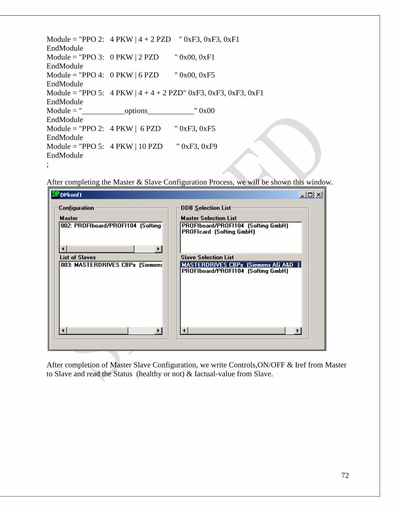
72
Module = "PPO 2: 4 PKW | 4 + 2 PZD " 0xF3, 0xF3, 0xF1
EndModule
Module = "PPO 3: 0 PKW | 2 PZD " 0x00, 0xF1
EndModule
Module = "PPO 4: 0 PKW | 6 PZD " 0x00, 0xF5
EndModule
Module = "PPO 5: 4 PKW | 4 + 4 + 2 PZD" 0xF3, 0xF3, 0xF3, 0xF1
EndModule
Module = "___________options____________" 0x00
EndModule
Module = "PPO 2: 4 PKW | 6 PZD " 0xF3, 0xF5
EndModule
Module = "PPO 5: 4 PKW | 10 PZD " 0xF3, 0xF9
EndModule
;
After completing the Master & Slave Configuration Process, we will be shown this window.
After completion of Master Slave Configuration, we write Controls,ON/OFF & Iref from Master
to Slave and read the Status (healthy or not) & Iactual-value from Slave.

73
Compile Binary File into VME default directory:
First of all, create a binary file named GECG28.BIN using following steps.
DPConfigurator → Download → Binary File → C:\ → PROGRA~1 → profibus → DP_KONF
→ GECG28.BIN
Fig. 4.24:- Compile binary file
74
CHAPTER 5
PROFIBUS & PROFIBUS VME INTERFACE CARD
5.1 PROFIBUS
PROCESS FIELD BUS (PROFIBUS) is an open, digital communication system. PROFIBUS is
the uniform, open automation technology for all fields of application, both in manufacturing
automation & in process automation. It provides a standardized automation technology for the
whole system.
PROFIBUS works as a communication link between master & slave devices in Master/Slave
architecture systems for very fast communication. The data transfer rate vary from 9.6 kbits/s to
12 Mbits/s depending upon the distance between two devices.
Over PROFIBUS, devices and systems communicate horizontally via standardized information
channels throughout the entire field level from the upstream area through the mainstream area to
the downstream area. PROFIBUS thus provides a standardized automation technology for the
entire system.
Apart from the system-wide transparency, there is a desire for standardization for different
applications and requirements. PROFIBUS is the uniform, open automation technology for all
fields of application, both in manufacturing automation & in process automation.
The modular PROFIBUS system reflects the entire range of PROFIBUS technology. It contains
specifications of technologies that are required for a complete description of communication
between network devices.
The specifications are arranged by function, thus allowing a modular structure of the PROFIBUS
system according to different technology areas. Combination of modules from different
technology areas permits the definition of an optimal communication solution for any
application.
The communication technology contains specifications that describe the physical/electrical and
optical properties of the device interfaces and the network. They include features like
communication medium, network topology, connection technology, signal characteristics, and
transfer rate.
Depending on the application, the possible device interfaces are RS 485, MBP, and fiber-optic
cables, as well as the intrinsically safe variants, RS 485-IS and MBP-IS. A combination of these
device interfaces is also feasible.

75
The communication technology contains specifications that describe the data structure and the
data exchange between the network devices, i.e. the communication mechanisms. There is the
only one PROFIBUS protocol, that is, Protocol DP (Decentralized Periphery) in stages DP-V0 to
DP-V2.
For closed-loop control tasks PROFIBUS uses purely cyclic data communication. This protocol
stage is referred to as DP-V0. If commissioning and monitoring functions have to be executed as
well, device data must be transferred acyclically. This functional extension is called DP-V1.
Other services provided by DP-V2 include time synchronization and time stamping.
If there is only one master, a PLC for closed-loop control tasks for example, the bus is accessed
cyclically using the master/slave procedure. In this case, the master is termed a Class 1 master.
Communication is controlled exclusively by the master. The network devices are passive and
may only become active, i.e. send data, if they have first been requested to do so by the master.
If there are several masters in a network, e.g. a PLC and a computer for device configuration, bus
access takes place by means of the token passing procedure. Within a defined time frame, each
master receives the bus access authorization, or token, which entitles it to control communication
during that time.

76
Fig. 5.1:- Token procedure in PROFIBUS
Application profiles are general specification that describe the properties, performance
capability, and behavior, no matter what make of device. A profile allows application-oriented
interaction of different makes of devices in a PROFIBUS network.
General application profiles describe functions and properties with cross-applicational
significance. They can be used in conjunction with the specific application profiles. General
application profiles are available for PROFIsafe, Time Stamp, Redundancy, and HART on
PROFIBUS.

77
The modular PROFIBUS system technology permits the definition of customized solutions
tailored to the application. For this purpose, modules are selected from various technology areas
and combined with one another.
Transmission Technology used for PROFIBUS
PROFIBUS can communicate via scheduled two-wire cables or fiber-optic cables. RS 485
transmits via a two-wire cable and is mainly used in factory settings. In the case of Manchester
coded Bus Powered (MBP) systems, power is also supplied to the field devices via a two-wire
line. Therefore, MBP is suitable for the explosion-protected zones in process automation.
Transmission via fiber-optic cables ensures electrical isolation, bridges long distances, and is
immune to EMC interference. Subnets comprised of RS 485 and MBP are connected with one

78
another in order to transmit data from the potentially explosive zone to the master device (CPU)
in the safe zone.
Closed circuit communication in accordance with the EIA RS 485 standard is defined as the
communication technology for PROFIBUS DP. It uses a shielded two-wire copper cable. In
environments subject to heavy interference and to increase the range, glass or plastic fiber-optic
cables are used.
Data transmission takes place byte by byte. The RS 485 interface adds one start bit, one stop bit,
and one parity bit to each information byte. This means that for each information byte comprised
of 8 bits, 11 bits are transferred over the cable. The frames thus have a high level of protection
against transmission errors.
In the case of RS 485-IS, power is supplied to the PROFIBUS devices via separate cable due to
the typically higher power demand.
For PROFIBUS PA, available communication technologies are MBP and the IS variants MBP-IS
and RS 485-IS in potentially explosive atmosphere. PROFIBUS PA networks are always linked
via DP-PA couplers to a PROFIBUS DP network.
Fiber Optic Transmission
An optical PROFIBUS network can be comprised of devices with an integrated optical interface
that are connected to one another in a line topology. Devices without an integrated optical
interface can be connected with their RS 485 interface via an Optical Bus Terminal (OBT).
Optical Link Modules (OLMs) have an isolated electrical channel and, depending on the type,
one or two optical channels. A single device or a complete PROFIBUS segment can be
connected to the RS 485 interface. Terminals with an integrated interface can be connected
directly to the optical interfaces. Terminals with an RS 485 interface are connected via an OBT
or OLM.
Transmission Rate
With RS 485, the transfer rate, which can be adjusted in increments of 9.6 kbits/s up to a
maximum of 12 Mbits/s, is dependent on the maximum length of the largest segment and the
physical properties of the weakest device in the PROFIBUS configuration.

79
MBP uses a fixed transmission rate of 31.25 kbits/s. Unlike RS 485, different transmission rates
are not possible with MBP.
Fiber-optic cables always cover the entire range of transmission rates that can be set for RS 485.
However, the physical properties of each of the active optical components have to be taken into
consideration.
The maximum network length is achieved by the concentration of segments of maximum length.
The number of segments depends on the type of repeater. With standard repeater (RS 485), up to
3 can be connected in series, while in the case of repeaters with signal refresh, up to 9 can be
connected in series.
Field Devices
In addition to the field devices themselves, the field components of a PROFIBUS system include
components like distribution boxes, cables, connectors, and terminators. Furthermore, other
components are used for the configuration of a field bus system, e.g. segment coupler, remote
I/O systems, overvoltage protection, barriers, and repeaters.
Protocol Architecture
PROFIBUS protocol architecture is based on the ISO/OSI reference model, standardized
internationally for communication tasks. The 7 layers define appropriate services and execution
rules for communication between two applications. There are user-oriented layers and network-
oriented layers.
Fig. 5.2:- OSI level of PROFIBUS
With PROFIBUS DP, Layer 7 is not characterized either. With this lean architecture, data
communication is extremely efficient and fast. For the user interface of PROFIBUS DP, the
direct access to the functions of layer 2 is implemented by the Direct Data Link Mapper
(DDLM).

80
Fig. 5.3:- PROFIBUS DP
PROFIBUS DP
PROFIBUS DP is an optimized-speed protocol, specially designed for low-cost communication
between a DP master and DP devices, i.e., the DP slaves. These include field equipment such as
sensors, actuators, measuring transducers, drives, and field multiplexers.
The performance capability of PROFIBUS DP comes into its own especially in mono-master
systems with unlimited bus access. The centralized control device requires a bus cycle time (that
is, the period of time in which all the slaves are polled once), which is shorter than the internal
processing time of the controller.
In the case of multi-master systems, the centralized control devices have to share bus access.
This often results in higher demands in terms of transfer rate (cost) or smaller data quantities
(performance) in order to guarantee the required bus cyclic time.
Prior to commencement of cyclic data transfer, initialization takes place between the DP master
and a DP slave. A check is performed in order to establish whether the set configuration agrees
with the actual device configuration, e.g. device type, format and length information, number of
inputs and outputs, etc.
In the first step, the DP master sends a diagnosis request to the DP slave. The diagnostic
response contains the station status, the PROFIBUS address of the DP master by which the slave
was parameterized, the manufacturer’s identifier, and device-specific diagnosis data.

81
If the result of slave diagnosis indicates that the DP slave has to be parameterized and
configured, the procedure continues with the parameter frame, which is acknowledged by the DP
slave.
After parameterization, the DP master has to send the set configuration to the DP slave. If the DP
slave discovers a deviation from its actual configuration, it generates appropriate diagnosis data
and is then not available for user data communication.
The result of the configuration test is polled by the DP master via a repeat diagnosis request
before it commences cyclic data communication with the DP slave.
In regular operation, cyclic data exchange takes place between the DP master and the DP slave.
With the SRD service (Send and Request Data), up to 244 bytes of output data and up to 244
bytes of input data can be exchanged in one frame.
Application Profile
Application Profile describes functions and properties with cross-applicational significance. The
“PROFIsafe” profile defines how safety-oriented devices, e.g. emergency OFF switches,
communicate with safety controls via PROFIBUS such that they can be used in safety-oriented
automation tasks up to CAT 4.
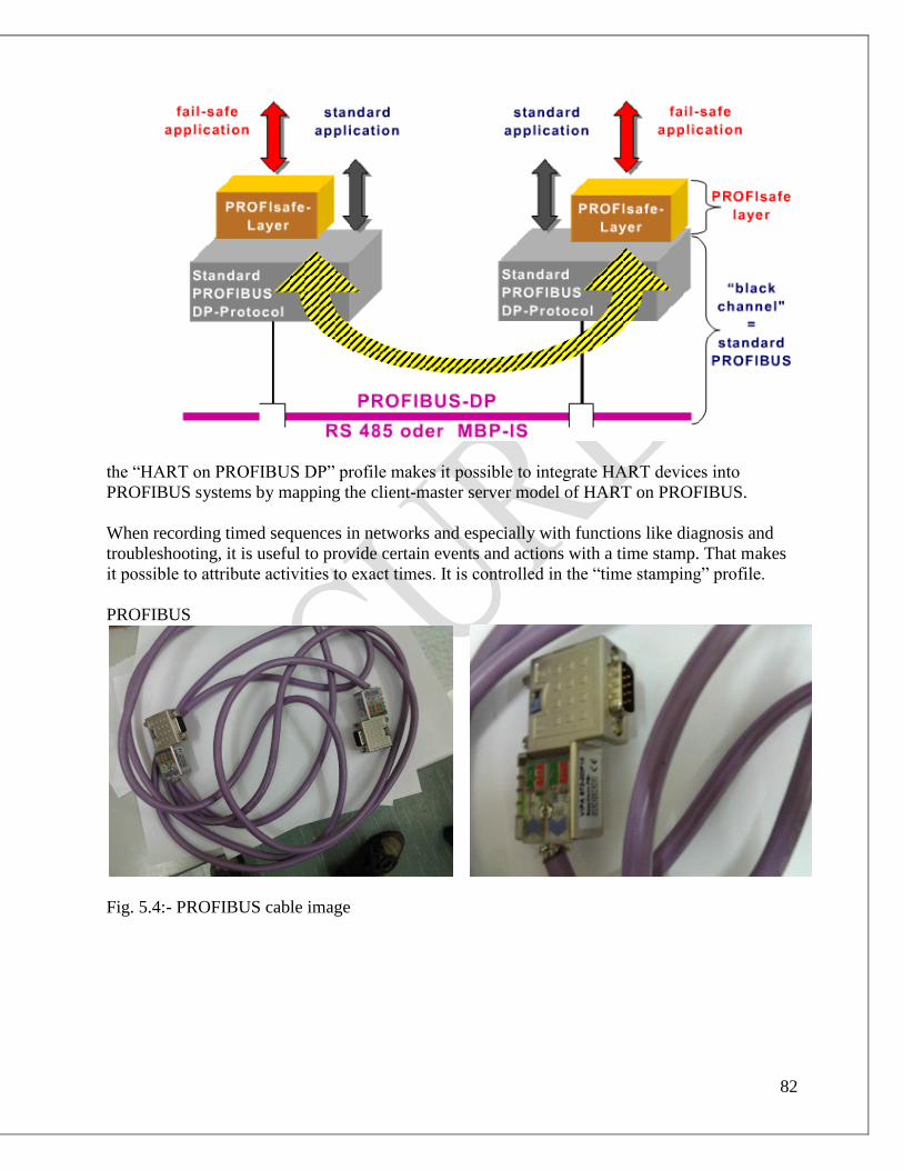
82
the “HART on PROFIBUS DP” profile makes it possible to integrate HART devices into
PROFIBUS systems by mapping the client-master server model of HART on PROFIBUS.
When recording timed sequences in networks and especially with functions like diagnosis and
troubleshooting, it is useful to provide certain events and actions with a time stamp. That makes
it possible to attribute activities to exact times. It is controlled in the “time stamping” profile.
PROFIBUS
Fig. 5.4:- PROFIBUS cable image
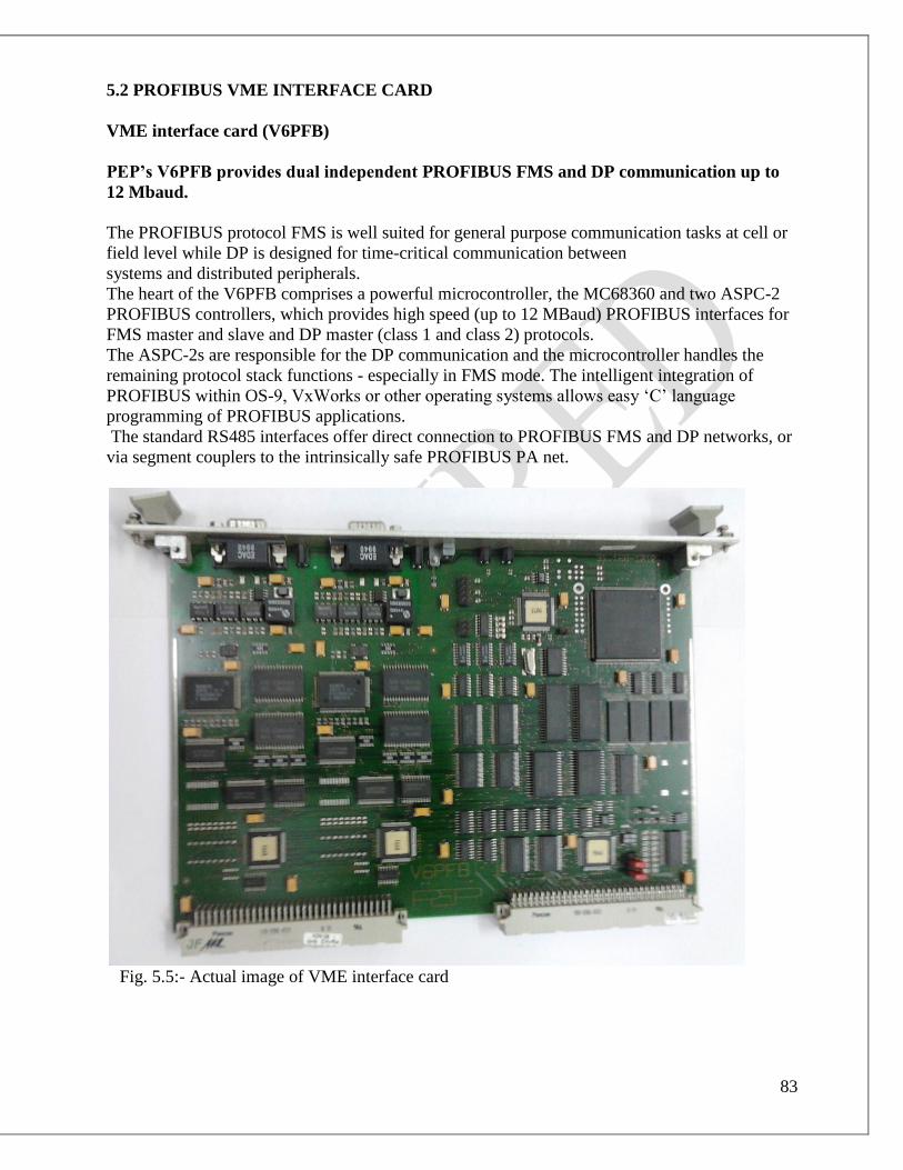
83
5.2 PROFIBUS VME INTERFACE CARD
VME interface card (V6PFB)
PEP’s V6PFB provides dual independent PROFIBUS FMS and DP communication up to
12 Mbaud.
The PROFIBUS protocol FMS is well suited for general purpose communication tasks at cell or
field level while DP is designed for time-critical communication between
systems and distributed peripherals.
The heart of the V6PFB comprises a powerful microcontroller, the MC68360 and two ASPC-2
PROFIBUS controllers, which provides high speed (up to 12 MBaud) PROFIBUS interfaces for
FMS master and slave and DP master (class 1 and class 2) protocols.
The ASPC-2s are responsible for the DP communication and the microcontroller handles the
remaining protocol stack functions - especially in FMS mode. The intelligent integration of
PROFIBUS within OS-9, VxWorks or other operating systems allows easy ‘C’ language
programming of PROFIBUS applications.
The standard RS485 interfaces offer direct connection to PROFIBUS FMS and DP networks, or
via segment couplers to the intrinsically safe PROFIBUS PA net.
Fig. 5.5:- Actual image of VME interface card
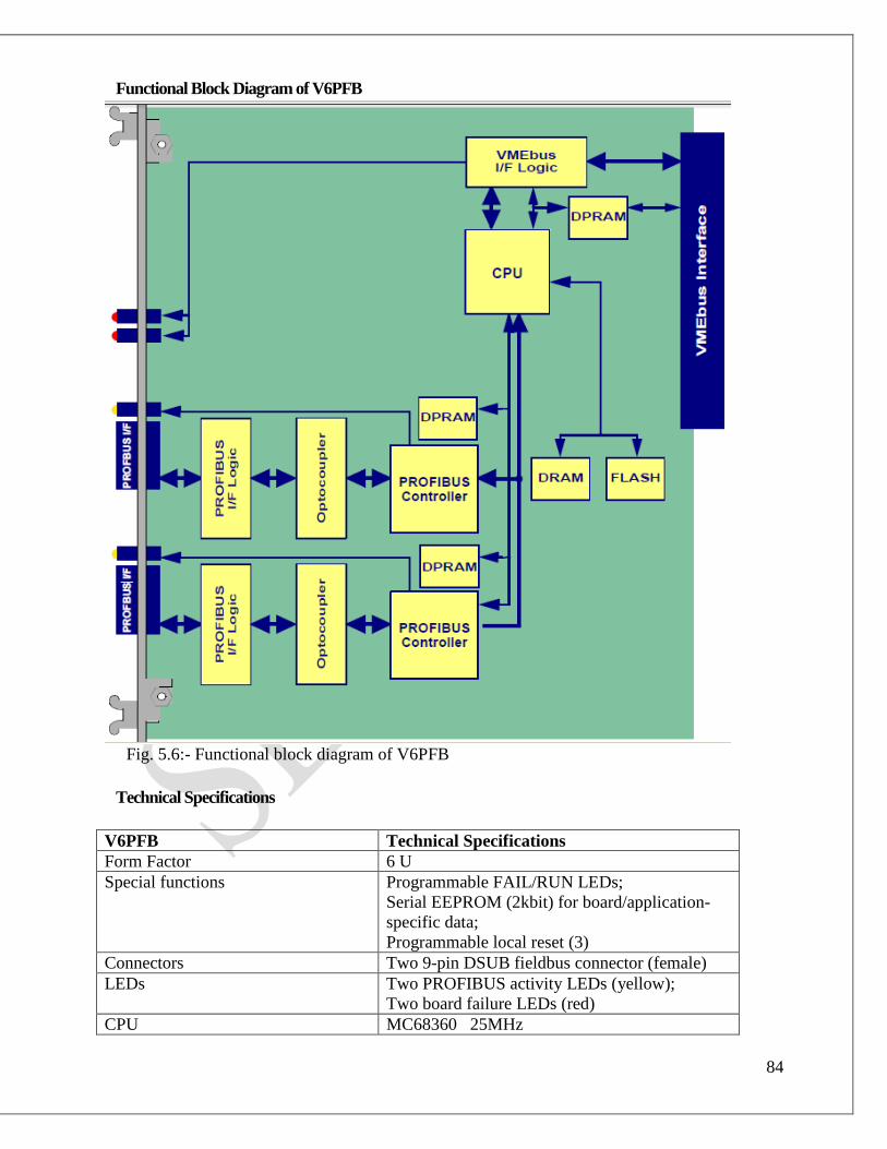
84
Functional Block Diagram of V6PFB
Fig. 5.6:- Functional block diagram of V6PFB
Technical Specifications
V6PFB Technical Specifications
Form Factor 6 U
Special functions Programmable FAIL/RUN LEDs;
Serial EEPROM (2kbit) for board/application-
specific data;
Programmable local reset (3)
Connectors Two 9-pin DSUB fieldbus connector (female)
LEDs Two PROFIBUS activity LEDs (yellow);
Two board failure LEDs (red)
CPU MC68360 25MHz
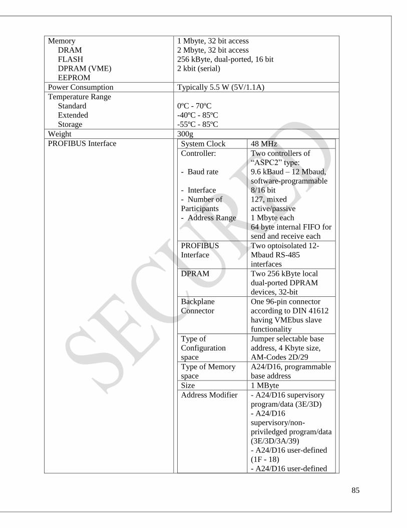
85
Memory
DRAM
FLASH
DPRAM (VME)
EEPROM
1 Mbyte, 32 bit access
2 Mbyte, 32 bit access
256 kByte, dual-ported, 16 bit
2 kbit (serial)
Power Consumption Typically 5.5 W (5V/1.1A)
Temperature Range
Standard
Extended
Storage
0ºC - 70ºC
-40ºC - 85ºC
-55ºC - 85ºC
Weight 300g
PROFIBUS Interface System Clock 48 MHz
Controller:
- Baud rate
- Interface
- Number of
Participants
- Address Range
Two controllers of
“ASPC2” type:
9.6 kBaud – 12 Mbaud,
software-programmable
8/16 bit
127, mixed
active/passive
1 Mbyte each
64 byte internal FIFO for
send and receive each
PROFIBUS
Interface
Two optoisolated 12-
Mbaud RS-485
interfaces
DPRAM Two 256 kByte local
dual-ported DPRAM
devices, 32-bit
Backplane
Connector
One 96-pin connector
according to DIN 41612
having VMEbus slave
functionality
Type of
Configuration
space
Jumper selectable base
address, 4 Kbyte size,
AM-Codes 2D/29
Type of Memory
space
A24/D16, programmable
base address
Size 1 MByte
Address Modifier - A24/D16 supervisory
program/data (3E/3D)
- A24/D16
supervisory/non-
priviledged program/data
(3E/3D/3A/39)
- A24/D16 user-defined
(1F - 18)
- A24/D16 user-defined

86
(17 - 10)
VME Interrupt 2* Mailbox Out,
programmable vector
base, level2. Pending
IRQ readable from local
side
Local Interrupt 2* Mailbox In, local
autovectored requests,
level 5 and 4. Pending
IRQ readable from VME
side
Table 5.1:- Technical specifications of V6PFB
V6PFB Front Panel
Two LEDs are positioned on the VFPB front panel having the following signalling function:
• Yellow ON: PROFIBUS interface transmit data;
• Red ON: board failure.
The board failure LED is controlled by the VMEbus interface.
Board Interface
VMEbus Connector
A 3-row by 32-pin connector according to VME standard enables data exchange between the
V6PFB slave interface and the system’s main control unit.
PROFIBUS Connector
Two 9-pin DSUB connectors enable data exchange of the V6PFB via two PROFIBUS RS485
fieldbus communication lines/network accesses providing RxD and TxD lines. The RTS signals
are used to enable transmitter operation.

87
V6PFB Board Overview
Fig. 5.7:- V6PFB board overview
V6PFB jumper setting of base address
J24 J25 J26 J23 Description
Close Close Close Close HEX 0000
Close Close Close Open HEX 1000
Close Close Open Close HEX 2000
Close Close Open Open HEX 3000
Close Open Close Close HEX 4000
Close Open Close Open HEX 5000
Close Open Open Close HEX 6000
Close Open Open Open HEX 7000
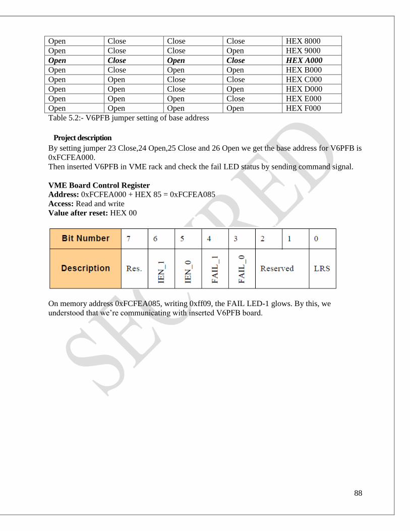
88
Open Close Close Close HEX 8000
Open Close Close Open HEX 9000
Open Close Open Close HEX A000
Open Close Open Open HEX B000
Open Open Close Close HEX C000
Open Open Close Open HEX D000
Open Open Open Close HEX E000
Open Open Open Open HEX F000
Table 5.2:- V6PFB jumper setting of base address
Project description
By setting jumper 23 Close,24 Open,25 Close and 26 Open we get the base address for V6PFB is
0xFCFEA000.
Then inserted V6PFB in VME rack and check the fail LED status by sending command signal.
VME Board Control Register
Address: 0xFCFEA000 + HEX 85 = 0xFCFEA085
Access: Read and write
Value after reset: HEX 00
On memory address 0xFCFEA085, writing 0xff09, the FAIL LED-1 glows. By this, we
understood that we’re communicating with inserted V6PFB board.

89
CHAPTER 6
6RA70 CHASIS & DRIVE MONITOR
6.1 6RA70 CHASIS
Fig. 6.1:- Internal view of 6RA70

90
Fig. 6.2:- CUD1

91
FUNCTION TERMINAL
X174
CONNECTION VALUES /
REMARKS
Reference M
P10
N10
1
2
3
±1% at 25 ºC; 10 mA short-circuit
proof
Select Input Main Setpoint+
Main Setpoint-
4
5
Input type parameterizable:
- Differential input ±10V; 150kΩ
Select Input Analog 1+
Analog 1-
6
7
- Current input 0-20 mA; 300Ω or
4-20 mA; 300Ω
Table 6.1:- Pin functions of CUD1
Binary Control Inputs

92
Binary Control Outputs
Serial interface 2 RS485 (G-SST2)
Pulse Encoder Input

93
Control Unit / Direct Current (CUD1)
Electronics board C98043-A7001 of SIMOREG DC-MASTER (Analog Outputs)
LBA(Local Bus Adapter):
Local Bus Adapter for the electronics box LBA is always needed to install supplementary
boards.
LBA for mounting supplementary boards
Optional supplementary boards can be installed only in conjunction with the LBA option. If an
LBA is not already fitted in the SIMOREG converter, one must be installed in the electronics
box to accommodate the optional board.
How to intall an LBA local bus adaptor in the electronics box
→ undo the two fixing screw on the CUD1 board and pull board out by special handles.
→ push LBA bue extension into electronics box until it engages.
→ insert CUD1 board in left-hand board location again and tight fixing screw in handles.
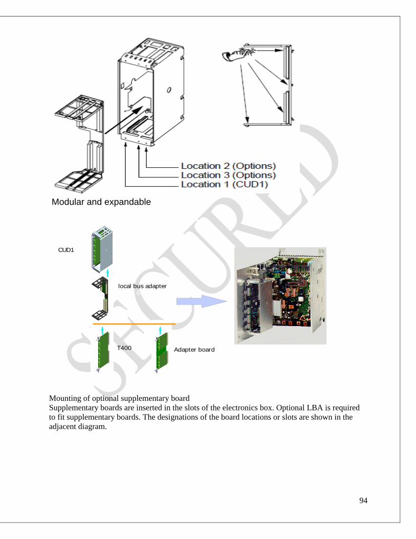
94
Mounting of optional supplementary board
Supplementary boards are inserted in the slots of the electronics box. Optional LBA is required
to fit supplementary boards. The designations of the board locations or slots are shown in the
adjacent diagram.
CUD1
local bus adapter (LBA)
T400 Adapter board(ADB)
Modular and expandable

95
Adapter Board (ABD)
ADB is always needed to install CBC, CBP, EB1, EB2, SBP and SLB boards.
SIMOLINK board (SLB)
Sequence of operation for starting up PROFIBUS boards (CBP2):
1. Switch off the power supply and insert the board or adapter with board.
2. The following are important communication parameters. Index 1 of each parameter is set
for the 1st communication board (1
st CB) and index 2 for the 2
nd CB:
- U712 PPO type, definition of the number of words in the parameter and process data
selection of the telegram (required only if the PPO type cannot be set via
PROFIBUS-DP master)
- U722 Telegram failure time for process data (0 = deactivated)
The DP master configuring data determine whether the slave (CBP2) must
monitor telegram traffic with the master. If this monitoring function is activated,
the DP master passes a time value (watchdog time) to the slave when the link is
set up. If no data are exchanged within this period, the slave terminates the
process data exchange with the SIMOREG converter. The latter can monitor the
process data as a function of U722 and activate fault message F082.
- P918 Bus address
- P927 Parameterization enabe (need only be set if parameters are to be assigned via
PROFIBUS)
- The process data of the 1st or 2
nd CB are connected by means of the appropriate
connectors and binectors. 3. Turn the electronics supply voltage off and on again or set U710.001 or U710.002 to “0”
to transfer the values of parameters U712, U722 and P918 to the supplementary board.
The CBP2 serves to link drives and higher-level automation systems via the PROFIBUS-DP. For
the purpose of PROFIBUS, it is necessary to distinguish between master and slave converters.
Masters control the data traffic via the bus and are also referred to as active nodes. There
are two classes of master:
DP master of class 1(DPM1) are central stations which exchange data with slaves in
predefined message cycles.
DPM1 support both a cyclic channel and an acyclic channel.
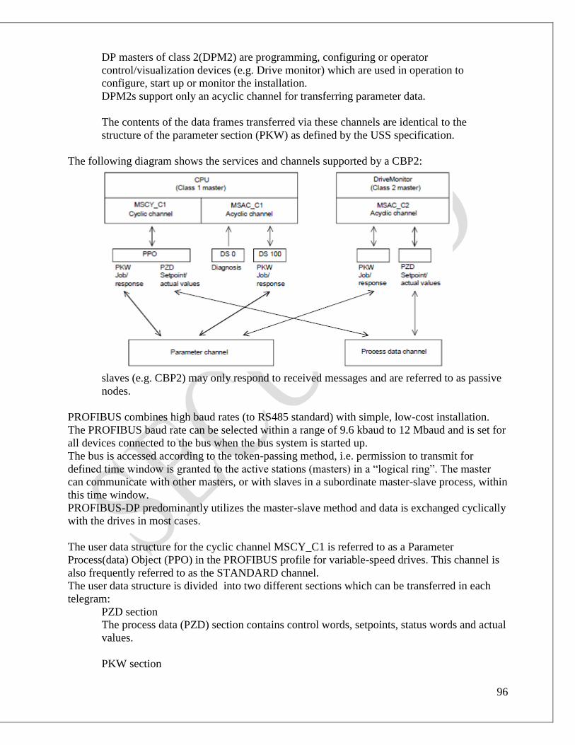
96
DP masters of class 2(DPM2) are programming, configuring or operator
control/visualization devices (e.g. Drive monitor) which are used in operation to
configure, start up or monitor the installation.
DPM2s support only an acyclic channel for transferring parameter data.
The contents of the data frames transferred via these channels are identical to the
structure of the parameter section (PKW) as defined by the USS specification.
The following diagram shows the services and channels supported by a CBP2:
slaves (e.g. CBP2) may only respond to received messages and are referred to as passive
nodes.
PROFIBUS combines high baud rates (to RS485 standard) with simple, low-cost installation.
The PROFIBUS baud rate can be selected within a range of 9.6 kbaud to 12 Mbaud and is set for
all devices connected to the bus when the bus system is started up.
The bus is accessed according to the token-passing method, i.e. permission to transmit for
defined time window is granted to the active stations (masters) in a “logical ring”. The master
can communicate with other masters, or with slaves in a subordinate master-slave process, within
this time window.
PROFIBUS-DP predominantly utilizes the master-slave method and data is exchanged cyclically
with the drives in most cases.
The user data structure for the cyclic channel MSCY_C1 is referred to as a Parameter
Process(data) Object (PPO) in the PROFIBUS profile for variable-speed drives. This channel is
also frequently referred to as the STANDARD channel.
The user data structure is divided into two different sections which can be transferred in each
telegram:
PZD section
The process data (PZD) section contains control words, setpoints, status words and actual
values.
PKW section
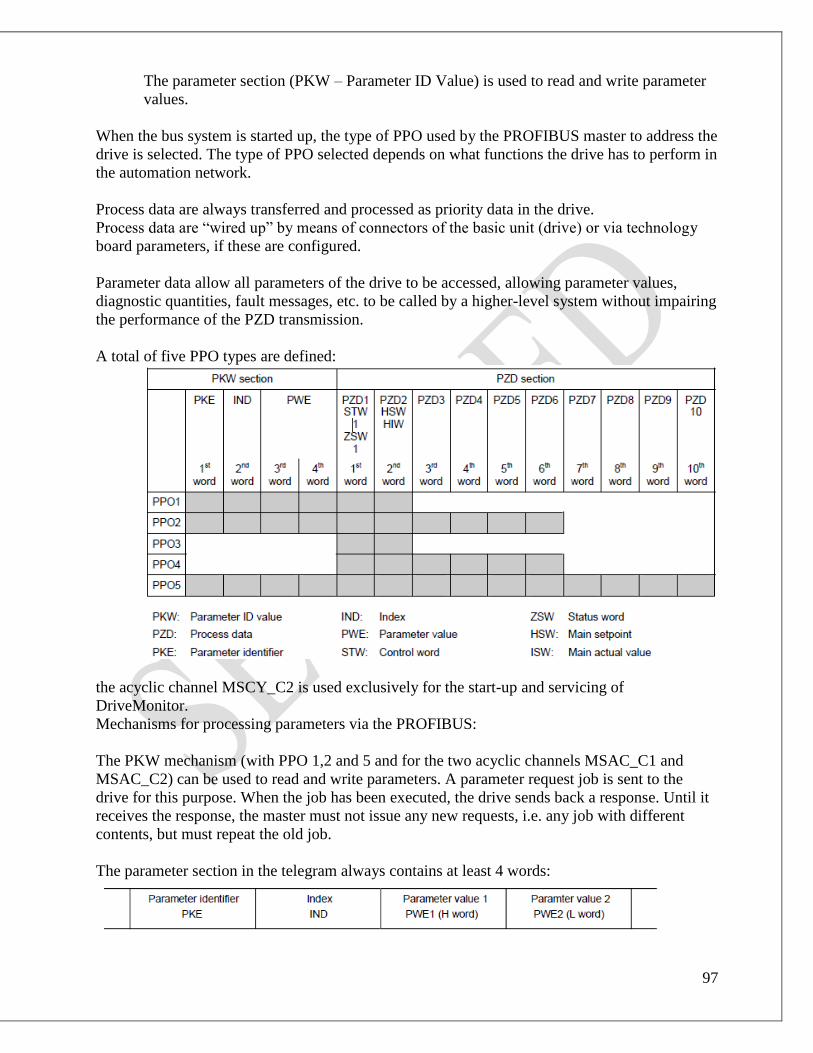
97
The parameter section (PKW – Parameter ID Value) is used to read and write parameter
values.
When the bus system is started up, the type of PPO used by the PROFIBUS master to address the
drive is selected. The type of PPO selected depends on what functions the drive has to perform in
the automation network.
Process data are always transferred and processed as priority data in the drive.
Process data are “wired up” by means of connectors of the basic unit (drive) or via technology
board parameters, if these are configured.
Parameter data allow all parameters of the drive to be accessed, allowing parameter values,
diagnostic quantities, fault messages, etc. to be called by a higher-level system without impairing
the performance of the PZD transmission.
A total of five PPO types are defined:
the acyclic channel MSCY_C2 is used exclusively for the start-up and servicing of
DriveMonitor.
Mechanisms for processing parameters via the PROFIBUS:
The PKW mechanism (with PPO 1,2 and 5 and for the two acyclic channels MSAC_C1 and
MSAC_C2) can be used to read and write parameters. A parameter request job is sent to the
drive for this purpose. When the job has been executed, the drive sends back a response. Until it
receives the response, the master must not issue any new requests, i.e. any job with different
contents, but must repeat the old job.
The parameter section in the telegram always contains at least 4 words:

98
The parameter identifier PKE contains the number of the relevant parameter and an identifier
which determines the action to be taken (e.g. “read value”).
The index IND contains the number of the relevant index value (equals 0 in the case of
nonindexed parameters). The IND structure differs depending on the communication mode:
- Definition in the PPOs (structure of IND with cyclical communication via PPOs)
- Definition for acyclical channels MSAC_C1 and MSAC_C2 (structure of IND with
acyclical communication)
The array subindex (referred to simply as “subindex” in the PROFIBUS profile) is an 8-bit value
which is transferred in the high-order bytes (bits 8 to 15) of the IND when data are transferred
cyclically via PPOs. The low-order byte (bits 0 to 7) is not defined in the DVA profile.the low-
order byte of the index word is used in the PPO of CBP2 to select the correct number range (bit7
= Page Select bit) in the case of parameter numbers of > 1999.
In the case of acyclical data traffic (MSAC_C1 , MSAC_C2) the number of the index is
transferred in the low-order byte (bits 0 to 7). Bit 15 in the high-order byte is used as the Page
Select bit. This assignment complis with the USS specification.
Index value 255 (request applies to all index values) is meaningful only for acyclical
transmission via MSAC_C1. the maximum data block length is 206 bytes with this transmission
mode.
The parameter value PWE is always transferred as double word (32-bit value) PWE1 and PWE2.
The high-order word is entered as PWE1 and low-order word as PWE2. in the case of 16-bit
values, PWE1 must be set to 0 by the master.
Rules for job/response processing:
A job or response can only ever refer to one parameter.
The master must send the job repeatedly until it receives an appropriate response from the
slave. The master recognizes the response to the job it has sent by analyzing the response
identifier, the parameter number, the parameter index and the parameter value.
The complete job must be sent in one telegram. The same applies to the response.
The actual values in repeats of response telegrams are always up-to-date values.
If no information needs to be fetched via the PKW interface (but only PZD) in cyclic
operation, then a “No job” job must be issued.
PROFIBUS devices have a variety of difference performance features. In order to ensure that all
master systems can correctly address each supplementary board, the characteristic features of
each board are stored in a separate device master files (GSD).
We need file <siem8045.gsd> for CBP2.
The appropriate file can be chosen in the selection menu for the SIMOVERT MASTER DRIVES
files in later versions of the configuring tool.
The communication boards can only be operated on a non-Siemens master as a DP standard
slave, the corresponding GSD file containing all necessary information for this mode.

99
Diagnostic tools:
LED displays of CBP2 (flashing LEDs means normal operation):
Red LED Status of CBP2
Yellow LED Communication between SIMOREG and CBP2
Green LED Communication between CBP2 and PROFIBUS
Fig. 6.3:- LED status of CBP2
6.2 DRIVE MONITOR
6.2.1 DRIVE MONITOR OVERVIEW
DriveMonitor is the start-up tool of Drive ES for drives belonging to the following families.
MICROMASTER
MASTERDRIVES
SIMOVERT
SIMOREG
Brief overview of the functions of DriveMon:
Parameterizing drives
Drive diagnostics
Entering setpoints

100
Operating modes
Drive converters can be parameterized both online and offline using DriveMon. DriveMon as
well as the SIMATIC Manager can be used to toggle between online and offline operation
Parameterizing types
Parameterization via lists
Graphic parameterization - basic functions
Graphic parameterization - technology functions
Parameter Set
Inserting or generating a parameter set via DriveMon
When DriveMon is open, parameter lists can be inserted or attached to all of the existing
projects. A new parameter set can be generated and linked to a project using the menu option
"File -> New -> Based on factory setting / Empty parameter set". An empty parameter list or
the factory setting can be selected.
The parameter set being currently processed can be inserted under another project for the same
drive converter and same software release via "File -> Save as ...".
Every parameter set in DriveMon has its own window.
Inserting or generating parameter sets via the SIMATIC Manager
In the SIMATIC Manager, parameters can only be inserted in parameter folders.
Proceed as follows:
1. In the SIMATIC Manager, select the parameter folder of the required drive (click once (1x)
with the left-hand mouse key on the parameter folder).
2. A new parameter set can be inserted as follows:
Using the SIMATIC Manager menu bar "Insert -> Parameter -> Parameter set" or
Using the context menu (click on the parameter folder using the right-hand mouse key)
"Insert new object -> Parameter set".
In the SIMATIC Manager, a new parameter set is always created as empty parameter set (i.e. it
does not contain any parameter values). In the SIMATIC Manager, parameter lists can be shifted
per drag and drop or copied. It is not permissible to copy into illegal object types (e.g. chart
folders).
Importing a parameter set via the SIMATIC Manager
An external parameter set (*.DNL file, generated, e.g. using DriveMonitor) can also be
integrated into the Drive ES project. Proceed as follows:
1. In the SIMATIC Manager, select the parameter folder of the required drive (with the left-hand
mouse key, on the parameter folder).
2. A new parameter set can be imported in the following ways:
Using the SIMATIC Manager menu bar "Insert -> external parameter..." or
Using the context menu (click on the parameter folder using the right-hand mouse key)
"Insert new object -> external parameter..."

101
Starting DriveMon
DriveMon is started from the SIMATIC Manager.
Start the offline mode (i.e. open and edit an existing parameter set).
1. In the SIMATIC Manager, open the parameter folder of the required drive/bus node and
select the parameter set to the opened.
2. DriveMon can be started as follows:
Double click on the selected parameter set (left-hand mouse key) or
Click on the parameter set with the right-hand mouse key and select "Open object" or
In the SIMATIC Manager via "Edit –> Open object".
Start the online mode (i.e. establish a communications link to the drive and read/change the
parameter values in the drive)
1. In the SIMATIC Manager, select the required drive (Caution: Not the bus interface, e.g.
mark CBP, but directly the drive, e.g. MASTERDRIVES MC).
2. DriveMon can be started as follows:
Click-on the drive with the right-hand mouse key and, in the context menu select the
following "Target system –> Drive -> Parameterization".
In the SIMATIC Manager via "Target system -> Drive -> Parameterization"
Please note:
When editing and working with parameter sets offline, the associated parameter set must
be marked, when parameterizing the unit online, the associated drive must be marked.
For every drive, DriveMon can be used to toggle between online and offline.
Further, parameter lists for other drives and projects can also be opened in DriveMon.
Several drives can be simultaneously opened in DriveMon. Each drive has its own window. In
the offline mode, drives from different projects can be opened.
DriveMon main window
The DriveMon window consists of:
Title line
with information on the project, drive and status
Menu line
with which you can activate all DriveMon functions
Function bar, with which you can activate important functions via Icons
Drive window
with different display options and operator action bar
General status line,
which contains the short help texts for the individual menu items.

102
The main window permits you to change, arrange, increase, decrease, minimize and maximize
the drive window which has been opened, as is usual for Windows 95 windows. However, for
reasons of transparency, it is recommended that the drive window with which you are presently
working, is maximized. It then fills the complete working area of the main window while the
inactive drive windows are invisible.
Note: If several drive windows are simultaneously open, then, for the inactive parameter
windows, only the unit status bar is updated, however, not the parameter values.
Toggling between several opened parameter windows
You can toggle between various open parameter windows using the menu option "Window
> Arrange"
Select one of the possibilities (Cascaded, Horizontally or Vertically) using the "Window >
Arrange" menu option
Result:
All the opened parameter windows are arranged corresponding to the selection made, and any
one of them can be brought to the foreground by simply clicking on it with the left-hand
mouse key (i.e. defined as active window).

103
Fig. 6.4:- Drive Monitor Active Window
Proceed as follows to close a parameter window:
Select the menu command File > Close device.
To exit DriveMon (close the main window), proceed as follows:
Select the menu command File > Exit.
Result:
The drive DriveMon application is closed and the system changes over into the SIMATIC
Manager.
Title line - DriveMon
In the title line, you can identify which drive you are presently working on and its operating
mode.
The title line of DriveMon includes
for maximized drive window
the names DriveMon, the project names, the drive names and the status of the active drive
online (RAM)
online (EEPROM)
offline (file name)
104
for a drive window which has not been maximized
the name DriveMon
the project name
of the drive name and the status are located in the title line of the drive window.
if a drive window has not been opened, then the title line only has the name DriveMon.
Drive window
Drive windows are opened to the maximum size, other settings (split window or minimized) are
established using "Window > Arrange" or using the buttons to the right in the title bar.
Title bar
If a drive window has not been maximized, the title bar shows the drive names and the status of
the active drive
online(RAM)
online(EEPROM)
offline(parameter set name)
If the drive window is maximized, the specified data/information is displayed in the title bar of
DriveMon.
Every drive window consists of
Parameter area or Drive Navigator
You can toggle between the parameter area and Drive Navigator as required.
Control bar
Parameter range
The parameter display range can be sub-divided into two independent sections. The active
section is identified by a thin blue frame (border). The inactive section is activated by clicking on
it using the left-hand mouse key:
In the active section, different views can be selected using the parameter, control and diagnostic
menus.
You can split parameter windows using the "Window > Split horizontally" menu option. In this
case, in each pane, different displays can be selected from the menu options, parameter, control
or diagnostics. The active pane has a blue frame. It is activated by clicking on it using the left-
hand mouse key. You can change the size of the pane by positioning the mouse pointer to the
line between the windows and then dragging it with the left-hand mouse key.
Contents of the parameter window when opening.
In the default setting, the "free parameterization" window is opened.
This means, you can enter those parameters, which you wish to view, in a dedicated list, and then
save this under "Parameter view".
Proceed as follows if you wish to display the complete parameter list when you start DriveMon:
Select the menu command Tools> Options.
The option dialog box opens.

105
Select the required setting in the "Pre-selection parameter window" field (empty parameter
window, complete parameter list or free parameterization).
Standard parameter table
With just a few exception (prompted start-up, trace), the Parameter and Diagnostic menus
open, under all of the menu options, the standardized table for displaying the parameters.
The parameter No., the plain text name, actual parameter value and the dimensions of the listed
parameters are entered in this table in columns P. No., Name, Parameter value and Dim. If the
current drive has indexed parameters, the Index and Index text columns are additionally
available in which, for indexed parameter, the index, and if available, the index text can be
displayed.
To change parameters, proceed as follows ("yellow" parameters (read-only parameters) cannot
be changed):
Using the left-hand mouse key, double click at any position in the appropriate line of the
table.
A window then opens to change the parameter value.
If the parameter to be changed is a "select parameter", select the new value from the text list
of possible parameter values and press OK.
If the parameter to be changed, is a "setting parameter", enter the new parameter value in the
"new value" input field and press OK. In order to monitor the limit values to be maintained,
also refer to offline mode (output-dependent parameters).
Parameter table
Column "P. No."
The parameter number is located in this column. It consists of a letter and three numbers.
Parameters which cannot be changed (parameters which can only be read) have lower-case
letters with a yellow background:
Parameters which can be changed have upper case letters and a green background:
Connectors are marked light-blue as opposed to parameters:
Binectors are marked dark-blue as opposed to parameters:
Column "index"
When you first open the parameter table, only the first index of indexed parameters is visible
(dependent on the type of the drive converter, index 000 or 001). In order to make all of the
parameter indices visible, click on the index symbol using the left-hand mouse key:
Now, all of the indices are displayed, the table contains the appropriate number of extra lines.
The index symbol changes to

106
Click on this if only the first index is to be displayed.
Operator control using the PC keyboard: The indices can be displayed or suppressed using the
<+> - or <-> - key of the numerical pad
Control bar
In the Control bar, you can enter a setpoint and ON- and OFF commands to the drive.
Prerequisites:
The drive is in the online mode (if this is not the case, the operator control line is gray and
cannot be used)
The drive is parameterized so that the setpoints and control commands are effective via the
interface (PROFIBUS or USS) of Drive ES.
Proceed as follows:
Enter a setpoint in the "Setpoint(%)" input field.
Click on the following:
Result: The drive is powered-up, the actual value is displayed in the control bar in the
"Actual value(%)" field.
Click on
Result: The drive is powered-down.
Unit status bar
The unit status bar is located at the lower edge of the DriveMon parameter window. You can use
this to obtain an overview of the status of the drive. The status display always refers to the drive
selected in the associated parameter window.
NOTE:
If several drive windows are simultaneously opened, then, for the windows which are
presently not active, only the drive status bars are updated, however, not the parameter
values themselves.
The actual drive converter status is displayed, next to the plain text messages such as ON, OFF,
OFFLINE, FAULT,... using an icon to the right next to the "drive status" field.
The color of these icons has the following significance:
Green: this drive is online and neither signals an alarm nor a fault.
Red: this drive is online and signals a fault.
Yellow: this drive is online and signals an alarm.
Blue: this drive is parameterized offline.
107
Black: DriveMon does not have a connection to the drive (the drive can only be
parameterized offline).
When in the online mode, the node address of the selected drive is displayed to the right of the
drive status icon. The drive connected to the bus system (PROFIBUS or USS) can be identified
via this address. The communications connection type between DriveMon and the drive can be
set using the DriveMon menu line: Tools> ONLINE settings > Bus type".
For MASTERDRIVES MotionControl and VectorControl devices with integrated tool
interface, the control bar is displayed in a different format and can be expanded to make a
drive control panel for operating the drive.
Splitting the drive window into two panes
Splitting the parameter display
Proceed as follows:
Select the menu command Window > Split horizontally.
Result: The parameter window is split.
Using the left-hand mouse key, click in one of the panes and then select the required contents
from the parameter, control or diagnostics menus.
Result: The required contents are displayed in the pane which was selected using the mouse.
Changing the size of the panes
The size of the pane can be changed by positioning the mouse pointer onto the line,
separating the panes and dragging the mouse to obtain the required size.
Operator control of the basic positioner
1. Go to the "Control/Observe" screen form and fetch the control command acceptance for the
drive onto your PC via the button "Request master control".
2. After the PC has accepted the control command the "drive control panel" will open.
Select "Input bits 1 to 6". This will set the drive to the ready-to-switch-on state.
3. You can now switch the drive ON and OFF via the green and red button. You can switch the
drive ON and OFF when the drive control panel is open and when it is minimized.
The drive can now be operated at variable speed via the drive control panel.
4. To operate the positioning functions activate the "Enabling Pos. Controller" button in the
"Control/Observe" screen form.
The "Release BPOS" LED should light up now.
5. The positioning functions can now be carried out via the corresponding fields and buttons.

108
Fig. 6.5 Drive Monitor response analysis window when No connection with 6RA70
6.2.2 DRIVE MONITOR CONFIGURATION
P051:- Access authorization levels
Key parameters
0 No access authorization
6 Do not set (for use by DriveMonitor)
7 Do not set (for use by DriveMonitor)
8 Do not set (for use by DriveMonitor)
21 Restore factory settings
All parameters are reset to their defaults. Parameter P051 is then
automatically reset to factory setting “40”.
22 Execute internal offset compensation
25 Optimization run for precontrol and current controller (armature and field)
26 Optimization run for speed controller
27 Optimization run for field weakening
28 Optimization run for compensation of friction and moment of inertia
29 Optimization run for the speed controller with an oscillating mechanical
system
30 Automatic setting of the parameters for SIMOREG CCP altered
parameters:
P351.i001, U577, U578, U800,
in the event of a fault, P790 if appropriate

109
40 Access authorization to parameter values for authorized service personnel
P790:- selection of protocol for G-SST2 basic converter interface
0 setting has no function
2 USS protocol
5 “peer to peer” communication
6 communication with the SIMOREG CCP
9 for internal factory test purposes
P927:- Parameterization enable
Enabling of interfaces for parameterization. A parameter value can only be altered via an
enabled interface.
0 None
1 Communications board(CB)
2 Parameterizing Unit (PMU)\
4 G-SST1 serial interface and OP1S
8 Reserved
16 Technology board (TB)
32 G-SST2 serial interface
64 G-SST3 serial interface
Setting information:
Every interface has a numeric code.
The number for one specifis interface, or the sum of various numbers assigned to several
interfaces, must be entered in this parameter in order to enable the relevant interface(s)
for use as a parameterization interface.
Example:
Factory setting value 6 (=4+2) means that the PMU and G-SST1 interfaces are enabled
for parameterization purposes.
P918:- CB bus address
Protocol-dependent bus address for communication boards
Note:
The availability of the bus address is monitored by the communication board. (Bus
addresses 0 to 2 are reserved for Master stations on PROFIBUS boards and must not
therefore be sent for other purposes). If the value is not accepted by the COM BOARD,
fault F080 is displayed with fault value 5.
n733:- CB/TB receive data
Display of control words and setpoints (process data ) that are transfeered to the basic
converter from a communication board(CB ) or technology board(TB).
i001: 1st process data word from 1
st CB/TB
..
..
i016: 16th
process data word from 1st CB/TB

110
i017 : 1st process data word from 2nd CB/TB
..
..
i032 : 16th
process data word from 2nd CB/TB
u734:- transmit data for first CB/TB
selection of connectors whose contents must be injected a transmit data to the first
communication board (CB) or technology board(TB).
0 = K0000
1 = K0001
etc.
this parameter not only defines the transmit data, but also their position in the transmit
telegram.
i001: word 1 in pzd section of telegram
i002: word 2 in pzd section of telegram
…..
i016: word 16 in pzd section of telegram
Status word 1(K0032)should be linked to word 1.
p785:- options for G-SST1
i001: 0 = Bus terminator OFF
1 = Bus terminator ON
i002: 0 = Bit 10 of the 1st receive word does not function as “Control by Master”
1 = Bit 10 of the 1st receive word does function as “Control by Master”, i.e. when
bit 10 = 0, all other bits of the 1st receive word, as well as receive words 2 to 16,
are not written to connectors K2001 to K2016, or to binectors B2100 to B2915.
All these connectors and binectors retain their old values.
n735:- Display of transmit data to CB/TB
i001: 1st process data word to 1
st CB or TB
…
i016: 16th
process data word to 1st CB or TB
i017: 1st process data word to 2
nd CB
…
i032: 16th
process data word to 2nd
CB
r001:- General visualization parameters
Display of terminals 4 and 5(main setpoint)
P701:- Normalization of “Main setpoint” analog input
This parameter specifies the percentage value which is generated for an input voltage of
10V (or an input current of 20mA) at the analog input.
The following generally applies:

111
For voltage input:
P701[%]=10V*Y/X X.. Input voltage in volts
Y.. % value which is generated for input voltage X
With current input:
P701[%]=20mA*Y/X X.. Input current in mA
Y.. % value which is generated for input current X
Fig. 6.6 Drive Monitor Run Time View

112
CHAPTER 7
PROGRAMME FILE OF SIMPLE DP /*****************************************************************************
@@COPYRIGHT
Copyright:
This source code is the proprietary confidential property of PEP Modular
Computers GmbH. Reproduction, publication, or any form of distribution to
any party other than the licensee is strictly prohibited.
@@END
@@FILEDESC
Filename: : simpledp.c
Description : Simple Profibus DP demoapplication
@@END
@@COMMON
Common description:
This simple DP-demo program initializes the protocol-stack and writes
to and reads from the DP-slave.
Configuration:
SlaveDevice: Siemens ET200B, 8 digital inputs and 8 digital ouputs
Master: Station 2
Slave: Station 13
Config-file: simpledp.cfg (.bin)
@@END
@@EDITION
Edition History
# date comments by
-- ---------- ------------------------------------------------------- ---
01 25-Jun-96 created RB
02 Jul/Aug-96 improved RB
03 28-Aug-96 released v5.01 I1.0 RB
04
05 25-Feb-97 Changed slave address to 13 RB
06 08-Sep-97 Ported to use new dpm.l library
07 May-98 IRQ- and mailboxtask handling modified RB
08 Jul-98 VxPFB support added RB
09 04-Dec-01 added pep version identifier, adapted to VxWorks SB
@@END

113
******************************************************************************
/
/* the following sequence will declare a character constant containing module
* name and version in the name and in the contents. A "." in the file name
* must be replaced by "_".
*/
#define PEP_MODNAME simpledp_c
#define PEP_VER_ID 09
#define PEP_VER_VARNAME_H(v,m,u) PEP_VER_##m##u##v
#define PEP_VER_VARNAME(v,m) PEP_VER_VARNAME_H(v,m,_)
#define PEP_VER_STR_H(m,v) "$PEPVERSION: " #m " " #v " $"
#define PEP_VER_STR(m,v) PEP_VER_STR_H(m,v)
#ifndef _ASMLANGUAGE
volatile static char PEP_VER_VARNAME(PEP_MODNAME,PEP_VER_ID)[]
__attribute__ ((unused)) = PEP_VER_STR(PEP_MODNAME,PEP_VER_ID);
#endif
#undef PEP_MODNAME
#undef PEP_VER_ID
#undef PEP_VER_VARNAME_H
#undef PEP_VER_VARNAME
#undef PEP_VER_STR_H
#undef PEP_VER_STR
#ifdef _OSK
_asm("_sysedit: equ 8");
#endif
/* includes */
/* for vxWorks support */
#include <stdlib.h>
#include <taskLib.h>
#include <ioLib.h>
#include <selectLib.h>
#include <signal.h>
#include <dp.h>
#include <profiv5.h>
#include "options.h"
/* defines */
#define SIGNAL 1 /* signaling required ? */

114
#define MAX_ARGC 20
#define SIGBUFSIZE 256
#define BIN_CFG_NAME "DP_DT.bin"
#define MASTER_DEFAULT_ADDRESS 0
#define LOWEST_SLAVE_ADDRESS 3
#define SLAVE_ADDRESS_MODE DP_AAM_COMPACT
#define DP_SLAVE_ADDRESS 3
/* tyedefs */
/* locals */
/*static path_id Path;*/
struct ConfigData
{
tBUS_PARAMETER_SET Bps;
tSLAVE_PARAMETER_SET Sps1;
OCTET GId1;
OCTET User_Data1[5];
USIGN16 Cfg_Data_Len1;
OCTET Cfg_Data1[2];
USIGN16 Add_Tab_Len1;
OCTET Add_Tab1[6];
USIGN16 Slave_User_Data_Len1;
} ConfigData;
/* extern declarations */
error_code SetSoftingDPConfig(
OCTET *pData,
long Size
);
/* globals */
u_int32 PollIntMode = POLLING_MODE;
long Signal;
long SigCount;
USIGN8 Service,
Primitive;
INT16 Result;
char ServiceResult[24][50] = {
"acknowledgement positive",
"remote user error",
"remote resource insufficient",
"remote service/SAP deactivated",
"access of remote SAP blocked",
"no reaction from remote station",
"local entity disconnected",

115
"not possible in this state",
"local resource not available",
"invalid parameter in request",
"timeout expired",
"format error in request frame",
"function not implemented",
"access denied",
"area too large",
"data block length exceeded",
"format error in response frame",
"invalid parameter",
"sequence conflict",
"sequence error",
"area non-existent",
"data incomplete",
"not connected",
"unknown result"
};
/* function prototypes */
u_int32 getpid(void);
/* functions */
void SetConfigData(void)
{
ConfigData.Bps.Fdl_Add = 2;
ConfigData.Bps.Baud_Rate = 4; /* 500 kbaud */
ConfigData.Bps.TSl = 500;
ConfigData.Bps.MinTsdr = 11;
ConfigData.Bps.MaxTsdr = 100;
ConfigData.Bps.TQui = 0;
ConfigData.Bps.TSet = 1;
ConfigData.Bps.TTr = 50000;
ConfigData.Bps.G = 10;
ConfigData.Bps.HSA = 126;
ConfigData.Bps.Max_Retry_Limit = 2;
ConfigData.Bps.Bp_Flag = 0;
ConfigData.Bps.Min_Slave_Interval = 100;
ConfigData.Bps.Poll_Timeout = 50;
ConfigData.Bps.Data_Control_Time = 20;
ConfigData.Bps.Master_User_Data_Len = 2+32+0;
ConfigData.Bps.Bus_Para_Len = sizeof( tBUS_PARAMETER_SET ) +
ConfigData.Bps.Master_User_Data_Len -2 -32;
ConfigData.Sps1.StationAddr = 3;
ConfigData.Sps1.Sl_Flag = 0xc0;
ConfigData.Sps1.Slave_Type = 0;

116
ConfigData.Sps1.Prm_Data_Len = 2+sizeof(tPRM_DATA)+1+5;
ConfigData.Sps1.Prm_Data.Station_Status = 0x08;
ConfigData.Sps1.Prm_Data.WD1 = 64;
ConfigData.Sps1.Prm_Data.WD2 = 1;
ConfigData.Sps1.Prm_Data.MinTsdr = 0;
ConfigData.Sps1.Prm_Data.IdH = 0x00;
ConfigData.Sps1.Prm_Data.IdL = 0x0b;
ConfigData.GId1 = 0;
ConfigData.User_Data1[0] = 0x11;
ConfigData.User_Data1[1] = 0;
ConfigData.User_Data1[2] = 0;
ConfigData.User_Data1[3] = 0;
ConfigData.User_Data1[4] = 0x77;
ConfigData.Cfg_Data_Len1 = 2+2;
ConfigData.Cfg_Data1[0] = 0x20;
ConfigData.Cfg_Data1[1] = 0x10;
ConfigData.Add_Tab_Len1 = 2+6;
ConfigData.Add_Tab1[0] = 1;
ConfigData.Add_Tab1[1] = 1;
ConfigData.Add_Tab1[2] = 0;
ConfigData.Add_Tab1[3] = 4;
ConfigData.Add_Tab1[4] = 0;
ConfigData.Add_Tab1[5] = 20;
ConfigData.Slave_User_Data_Len1 = 2+0;
ConfigData.Sps1.Slave_Para_Len = sizeof( tSLAVE_PARAMETER_SET ) -2 +
ConfigData.Sps1.Prm_Data_Len - sizeof(tPRM_DATA) -2 +
ConfigData.Cfg_Data_Len1 + ConfigData.Add_Tab_Len1 +
ConfigData.Slave_User_Data_Len1;
}
void AppDeinit(void)
{
DPDeinit();
MBTaskDeinit();
DPUnloadConfig();
}
void SigHand( u_int32 signal )
{
/*
Signal = signal;
if( Signal < 32 )
{
AppDeinit();
exit(Signal);
}
SigCount++;
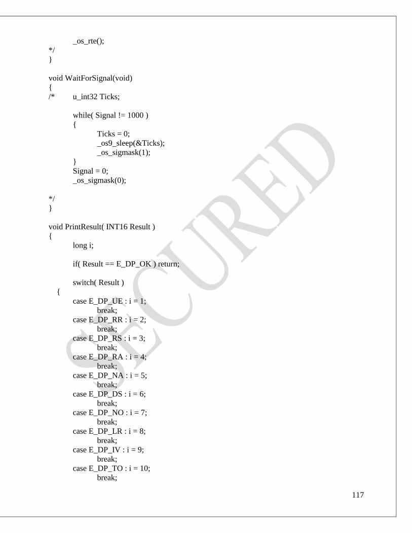
117
_os_rte();
*/
}
void WaitForSignal(void)
{
/* u_int32 Ticks;
while( Signal != 1000 )
{
Ticks = 0;
_os9_sleep(&Ticks);
_os_sigmask(1);
}
Signal = 0;
_os_sigmask(0);
*/
}
void PrintResult( INT16 Result )
{
long i;
if( Result == E_DP_OK ) return;
switch( Result )
{
case E_DP_UE : i = 1;
break;
case E_DP_RR : i = 2;
break;
case E_DP_RS : i = 3;
break;
case E_DP_RA : i = 4;
break;
case E_DP_NA : i = 5;
break;
case E_DP_DS : i = 6;
break;
case E_DP_NO : i = 7;
break;
case E_DP_LR : i = 8;
break;
case E_DP_IV : i = 9;
break;
case E_DP_TO : i = 10;
break;

118
case E_DP_FE : i = 11;
break;
case E_DP_NI : i = 12;
break;
case E_DP_AD : i = 13;
break;
case E_DP_EA : i = 14;
break;
case E_DP_LE : i = 15;
break;
case E_DP_RE : i = 16;
break;
case E_DP_IP : i = 17;
break;
case E_DP_SC : i = 18;
break;
case E_DP_SE : i = 19;
break;
case E_DP_NE : i = 20;
break;
case E_DP_DI : i = 21;
break;
case E_DP_NC : i = 22;
break;
default: i = 23;
break;
}
printf("%s\n", ServiceResult[i] );
}
PB_BOOL GetResult(char *func, USIGN8 ReqService)
{
error_code err;
error_code ret;
PB_BOOL status = PB_TRUE;
#ifdef DEBUG
int resultCnt = 0;
#endif
/* wait for confirmation: */
do
{
#ifdef DEBUG
resultCnt ++;
#endif
if( PollIntMode == IRQ_MODE )

119
{
WaitForSignal();
printf("%ld signals received so far\n", SigCount );
}
ret = DPRcvConInd( &Service, &Primitive, &Result );
#ifdef DEBUG
if( (ret == NO_CON_IND_RECEIVED) && (resultCnt < 1000) )
{
taskDelay(1);
continue;
}
#else
if( ret == NO_CON_IND_RECEIVED ) continue;
#endif
if( Service != ReqService )
{
printf("*");
fflush(stdout);
}
}
#ifdef DEBUG
while( (!(ret != NO_CON_IND_RECEIVED && Service == ReqService)) &&
(resultCnt < 1000));
#else
while( !(ret != NO_CON_IND_RECEIVED && Service == ReqService) );
#endif
printf("\n%s ", func );
fflush( stdout );
/* complete error-handling: */
if( ret == CON_IND_RECEIVED )
{
err = DPGetConIndStatus();
if( err == E_OK )
{
printf(" was successful\n");
}
else
{
printf(" failed with errors %d / %d\n", err, DpError );
AppDeinit();
status = PB_FALSE;
}
}
else
{
#ifdef DEBUG

120
printf("recieved error %d, resultCnt = %d\n", ret, resultCnt);
#else
printf("recieved error %d\n", ret );
#endif
AppDeinit();
status = PB_FALSE;
}
#ifdef DEBUG
printf("resultCnt =%d\n",resultCnt);
#endif
return status;
}
/* void main(int argc, char **argv) */
STATUS simpledp ( char *param )
{
/* Added for Tornado to assume main (int argc, char *argv[]) compatibility */
int argc; /* Argument number including main() */
char *argv[MAX_ARGC]; /* Array for the argument strings */
error_code error, ret;
long i,
cnt=0;
u_int16 HostAccess,
HostCpu;
u_int32 DpramBaseAddr,
HostVmeMBAddr,
HostLocalMBAddr,
HostMBSize,
HostMBSetValue,
HostMBResetValue,
RegBaseAddr, /* required for VxPFB */
/* count=0,*/
SlaveAddr,
ReadFile,
Ticks;
USIGN8 Data[256],
RemoteAddress = DP_SLAVE_ADDRESS,
Length;
UINT32 usedConfigurator = 0;
u_int32 Vector = PEP_DEFAULT_VECTOR;
USIGN16 DataLength;
PB_BOOL status;
char str[80];
HostAccess = CPU_REMOTE; /* default */

121
HostCpu = CPU_OTHER;
DpramBaseAddr = 0x87002000; /* dummy, value not required for
CPU_LOCAL-access */
HostVmeMBAddr = 0xfcfe0083;/*0; changed for testing sajeed*/
HostLocalMBAddr = 0;
HostMBSize = 1;
HostMBSetValue = 0;
HostMBResetValue = 0;
RegBaseAddr = 0x8500c000; /* no VxPFB board used */
SigCount = 0;
ReadFile = 1;
/* Clean the argv[] array */
for (i=0; i<MAX_ARGC; i++) argv[i]= "\0";
/* Assume the argc, char *argv[] values in function of ParStr string */
t_PatchMain (param, &argc, argv);
/* setup host-configuration: */
/* error = _os_intercept( (void*) SigHand, _glob_data );
if( error )
{
printf("Error %d on _os_intercept() ... exit\n", error);
exit(error);
}
*/
for (i = 1; i < argc; i++)
{ /* additional library function, for flexible use of this demo: */
if (GetProgramOptions ( (char *) argv[i], &HostAccess, &HostCpu,
&DpramBaseAddr, &HostVmeMBAddr,
&HostLocalMBAddr,
&HostMBSize, &HostMBSetValue,
&HostMBResetValue) != OK)
{
return(ERROR);
}
if( strncmp( argv[i], "-sa=", 4 ) == 0 )
{
sscanf(argv[i]+4, "%d", &SlaveAddr );
printf("Slave address: %d\n", SlaveAddr );
RemoteAddress = (USIGN8) SlaveAddr;
}
else if( strncmp( argv[i], "-v=", 3 ) == 0 )
{
sscanf(argv[i]+3, "%d", &Vector );
printf("Irq vector: %d\n", Vector );
}
else if( strncmp( argv[i], "-regbase=", 9 ) == 0 )
{

122
sscanf(argv[i]+9, "%x", &RegBaseAddr );
printf("RegBaseAddr: %x\n", RegBaseAddr );
}
else if (strncmp (argv[i], "-irq", 4) == 0)
{
PollIntMode = IRQ_MODE;
printf ("Using IRQs\n");
}
else if (strncmp (argv[i], "-nofile", 4) == 0)
{
ReadFile = 0;
printf ("Using compiled data\n");
}
else if( strncmp( argv[i], "-conf=", 6 ) == 0 )
{
sscanf(argv[i]+6, "%d", &usedConfigurator );
printf("used Configurator: %d\n", usedConfigurator );
}
}
error = DPMLibInit( PB_V5X );
DPSetController(0);
DPSetConfigurator((UINT8)usedConfigurator);
printf("Calling SetHostConfiguration\n");
error = SetHostConfiguration (&DpramBaseAddr, RegBaseAddr, HostCpu, HostAccess,
HostVmeMBAddr, HostLocalMBAddr, HostMBSize, HostMBSetValue, HostMBResetValue);
printf("SetHostConfiguration Executed\n");
if (error)
{
printf ("SetHostConfiguration() returned error %d\n", error);
return (ERROR);
}
else
{
printf ("SetHostConfiguration ok\n");
}
error = MBTaskInit (DpramBaseAddr, Vector, 1000, PollIntMode);
if (error)
{
printf ("Error init mailboxtask %d\n", error);

123
MBTaskDeinit();
return (ERROR);
}
else
{
printf ("Mailboxtask init ok\n");
}
if(ReadFile)
{
if ( (error = DPLoadConfig(BIN_CFG_NAME)) != E_OK /*&& error !=
E_DP_SLAVE_PARA_FAULT */)
{
printf("Configurationfile '%s' not found\n",BIN_CFG_NAME);
/* For compatibility with previous releases: */
if ( (error = DPLoadConfig(BIN_CFG_NAME)) != E_OK )
{
MBTaskDeinit();
return(ERROR);
}
printf("Using configurationfile '%s' \n",BIN_CFG_NAME);
}
else
{
printf("Using configurationfile '%s'\n",BIN_CFG_NAME);
}
}
else
{
SetConfigData();
error = DPSetConfig((OCTET*) &(ConfigData.Bps), (long) sizeof(struct
ConfigData));
if ( error != E_OK && error != E_DP_SLAVE_PARA_FAULT )
{
printf("Configuration fault\n");
MBTaskDeinit();
return(ERROR);
}
else
{
printf("Using hard-coded configuration\n");
}
}
printf ("\n\nHostCpu = %x \n", HostCpu);
printf ("DpramBaseAddr %x\n", DpramBaseAddr);

124
printf ("HostAccessMode %x\n", HostAccess);
printf ("Host VME Mailbox addr %x\n", HostVmeMBAddr);
printf ("Host Local Mailbox addr %x\n", HostLocalMBAddr);
printf ("Host Mailbox size %x\n", HostMBSize);
printf ("Host Mailbox IRQ-set-value %x\n", HostMBSetValue);
printf ("Host Mailbox IRQ-reset-value %x\n", HostMBResetValue);
printf ("Register base address of VxPFB %x\n", RegBaseAddr );
printf ("\n");
/* Now initialize the Profibus protocol stack: */
error = DPInit( DpramBaseAddr );
if ( error != E_OK )
{
printf("DPInit() failed !\n");
MBTaskDeinit();
return(ERROR);
}
printf("DPInit() ok!\n");
DPSetMasterDefaultAddress( MASTER_DEFAULT_ADDRESS );
DPSetMasterClass2( PB_FALSE );
DPSetLowestSlaveAddress( LOWEST_SLAVE_ADDRESS );
DPSetSlaveAddressMode( SLAVE_ADDRESS_MODE );
DPSetClearOutputsOnInit( PB_TRUE );
DPSetAutoRemoteServices( DP_USER_REMOTE_SERVICES );
DPSetCyclicDataTransfer( PB_TRUE );
error = DPInitMasterReq();
if( GetResult("DPInitMasterRequest", DP_INIT_MASTER ) != PB_TRUE )
{
PrintResult( error );
DPUnloadConfig();
MBTaskDeinit();
return(ERROR);
}
error = DPDownloadLocReq( MASTER_DEFAULT_ADDRESS, RemoteAddress, 0 );
sprintf(str, "DPDownloadLocReq (%d)", RemoteAddress );
if( error != E_OK || GetResult(str, DP_DOWNLOAD_LOC ) != PB_TRUE )
{
PrintResult( error );
DPUnloadConfig();
MBTaskDeinit();
return(ERROR);
}
error = DPDownloadLocReq( MASTER_DEFAULT_ADDRESS, 127, 0 );
if( error != E_OK || GetResult("DPDownloadLocReq (127)", DP_DOWNLOAD_LOC )
!= PB_TRUE )
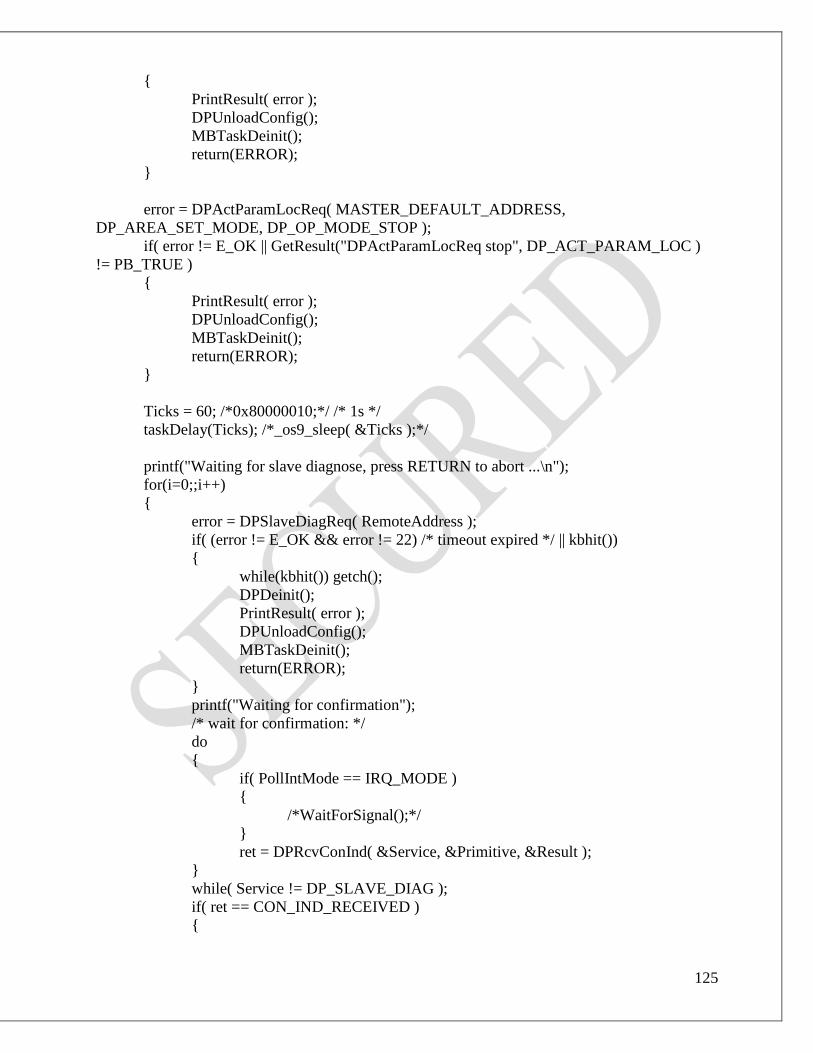
125
{
PrintResult( error );
DPUnloadConfig();
MBTaskDeinit();
return(ERROR);
}
error = DPActParamLocReq( MASTER_DEFAULT_ADDRESS,
DP_AREA_SET_MODE, DP_OP_MODE_STOP );
if( error != E_OK || GetResult("DPActParamLocReq stop", DP_ACT_PARAM_LOC )
!= PB_TRUE )
{
PrintResult( error );
DPUnloadConfig();
MBTaskDeinit();
return(ERROR);
}
Ticks = 60; /*0x80000010;*/ /* 1s */
taskDelay(Ticks); /*_os9_sleep( &Ticks );*/
printf("Waiting for slave diagnose, press RETURN to abort ...\n");
for(i=0;;i++)
{
error = DPSlaveDiagReq( RemoteAddress );
if( (error != E_OK && error != 22) /* timeout expired */ || kbhit())
{
while(kbhit()) getch();
DPDeinit();
PrintResult( error );
DPUnloadConfig();
MBTaskDeinit();
return(ERROR);
}
printf("Waiting for confirmation");
/* wait for confirmation: */
do
{
if( PollIntMode == IRQ_MODE )
{
/*WaitForSignal();*/
}
ret = DPRcvConInd( &Service, &Primitive, &Result );
}
while( Service != DP_SLAVE_DIAG );
if( ret == CON_IND_RECEIVED )
{

126
error = DPSlaveDiagCon( &RemoteAddress, &DataLength, (OCTET*)
Data );
if( error != E_OK )
{
if( !(i%10) ) PrintResult( error );
Ticks = 10;
taskDelay(Ticks); /*_os9_sleep( &Ticks );*/
}
else
{
printf("Diag-data (length = %d):\n", DataLength);
for( i=0; i<DataLength && i<256; i++ )
{
printf("0x%x ", (u_int32) Data[i] );
}
printf("\n--- end ---\n");
break; /* exit loop when diag message received */
}
}
}
taskDelay(sysClkRateGet()*5); /* stack needs some time to start up */
error = DPGetCfgReq( RemoteAddress );
if( error != E_OK )
{
PrintResult( error );
DPDeinit();
DPUnloadConfig();
MBTaskDeinit();
return(ERROR);
}
/* wait for confirmation: */
printf("Waiting for CFG-data ...\n");
do
{
if( PollIntMode == IRQ_MODE )
{
/* wait for IRQ from stack: */
WaitForSignal();
}
ret = DPRcvConInd( &Service, &Primitive, &Result );
if( ret == NO_CON_IND_RECEIVED ) continue;
}
while( Service != DP_GET_CFG );
printf("ok\n"); fflush(stdout);

127
if( ret == CON_IND_RECEIVED )
{
error = DPGetCfgCon( &DataLength, (OCTET*) Data );
if( error != E_OK )
{
PrintResult( error );
}
else
{
printf("Config-data (length = %d):\n", DataLength);
for( i=0; i<DataLength && i<256; i++ )
{
printf("0x%x ", (u_int32) Data[i] );
}
printf("\n--- end ---\n");
}
}
error = DPActParamLocReq( MASTER_DEFAULT_ADDRESS,
DP_AREA_SET_MODE, DP_OP_MODE_CLEAR );
if( error != E_OK || GetResult("DPActParamLocReq clear ", DP_ACT_PARAM_LOC )
!= PB_TRUE )
{
PrintResult( error );
DPUnloadConfig();
MBTaskDeinit();
return(ERROR);
}
error = DPActParamLocReq( MASTER_DEFAULT_ADDRESS,
DP_AREA_SET_MODE, DP_OP_MODE_OPERATE );
if( error != E_OK || GetResult("DPActParamLocReq operate", DP_ACT_PARAM_LOC
) != PB_TRUE )
{
PrintResult( error );
DPUnloadConfig();
MBTaskDeinit();
return(ERROR);
}
Ticks = 10; /*0x80000100;*/
taskDelay(Ticks); /*_os9_sleep( &Ticks );*/
/* now enter loop to read and write the slave: */
Length = 4;/*changed by sajeed*/
fflush(STD_IN);
printf("Address of Data is: %x",&Data[0]);

128
do
{
if( (cnt%1000) == 0 )
{
/* without taskDelay the host shell does not get enough time to */
/* print, so some printfs might get lost */
taskDelay(1);
error = DPReadIOByAddReq( RemoteAddress, &Length, Data );
if( error == E_OK )
{
printf("%d bytes read: ", Length );
fflush( stdout );
for( i=0; i<Length && i < 20; i++ ) printf("%4x", Data[i] );
printf("\n");
}
}
else
{
Data[0] = cnt;/*0x11; /*cnt; set to provide a constant value sajeed*/
Data[0] = 0xff;/*just to check the integrity changed by dinesh0x11; /*cnt;
set to provide a constant value sajeed*/
status = DPWriteIOByAddReq( RemoteAddress, 1, Data );
}
cnt++;
/*error = _os_gs_ready( stdin->_fd, &count );*/
/*if( error != 0 ) count = 0;*/
}
/* exit, when keyboard hit */
while( ! kbhit() /*count<=0*/ );
while(kbhit()) getch();
DPDeinit();
/* Now deinitialize the Profibus protocol stack: */
Ticks = 10; /*0x80000100;*/
taskDelay(10/*Ticks*/); /*_os9_sleep( &Ticks );*/
MBTaskDeinit();
DPUnloadConfig();
printf("\n --- End ---\n");
return(OK);
}
/* END OF FILE */

129
CHAPTER 8
Execution of data transfer between CBP2 module and VME interface card
through PROFIBUS
1. As shown in fig.1 the connection between the 6RA70 drive master controller and laptop is
done by DB9 pin connection and with VME system by PROFIBUS cable for analog data
transfer.
Fig. 8.1:- Connection between 6RA70 & VME system
2. On 6RA70, there are analog channel inputs where we can apply 0 to 10 V dc on pin number 4
& 5. as shown in the figure, we are giving 4 V dc supply to analog channel input of 6RA70.

130
Fig. 8.2:- Input reference signal
and the reference signal (4 V dc) is converted into digital (HEX value) by 6RA70 controller that
is shown in following figure.
Fig. 8.3:- Communication Status by viewing LEDs
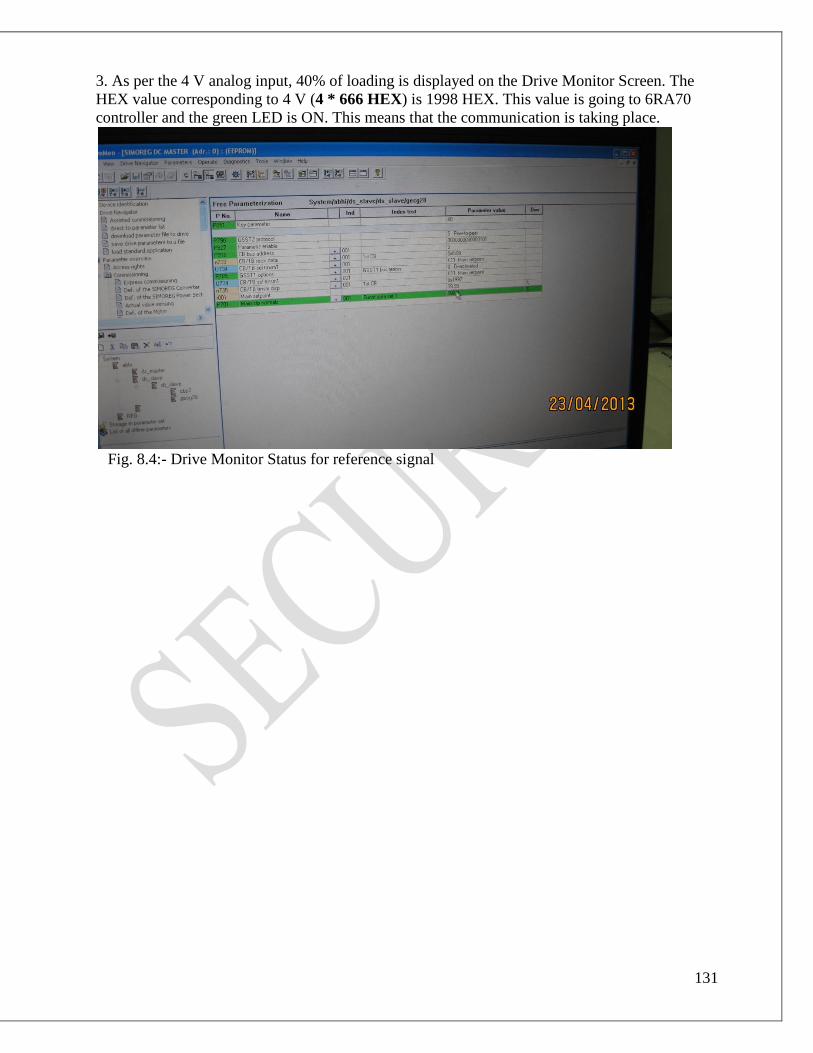
131
3. As per the 4 V analog input, 40% of loading is displayed on the Drive Monitor Screen. The
HEX value corresponding to 4 V (4 * 666 HEX) is 1998 HEX. This value is going to 6RA70
controller and the green LED is ON. This means that the communication is taking place.
Fig. 8.4:- Drive Monitor Status for reference signal

132
Fig. 8.5:- Screen shot related to fig. 8.4

133
4. the corresponding HEX value (1998 H) is transferred to the VME interface card by
PROFIBUS as shown in following figure.
Fig. 8.6:- Data transfer through VME interface card
5.The same value through VME rack and processor is displayed on shell window from VME
interface card.

134
6. Now, from Tornado Shell, the data ff H is written from the master to slave number3 and again
this data will go to VME interface card. Through PROFIBUS, this data will go to 6RA70
controller CBP2 module.

135
7. The same data we’ll monitor on the receiving buffer of Drive Monitor.

136
8. Thus, the two way communication takes place. Every time 4 bytes are being read and 4 bytes
are written.

137
APPLICATION:-
• 6RA70 6,12 pulse converter is used as the firing of TF & PF.
• In other power supplies where 6,12 pulse conerter is required; the 6RA70
pulse converter is usable.

138
CONCLUSION:-
• We learnt Real Time Operating Systems of VME (TORNADO), Drive
Monitor software of Controller & Interfacing of two different systems.

139
REFERENCE:-
1. The VMEbus Handbook,4th Edition by Wade D. Peterson, VITA 1997 pp 3-10.
2. tornado Training workshop VOL1.
3. www.vita.com
4. www.ipr.res.in
5. www.windriver.com
6. http://www.wrs.com/training
7. User manual of AVME 9668 acromag
8. User manual of IP330 acromag
9. Siemens Energy & Automation