Embedded Crack Identification in Beam-Column Structures ...
12
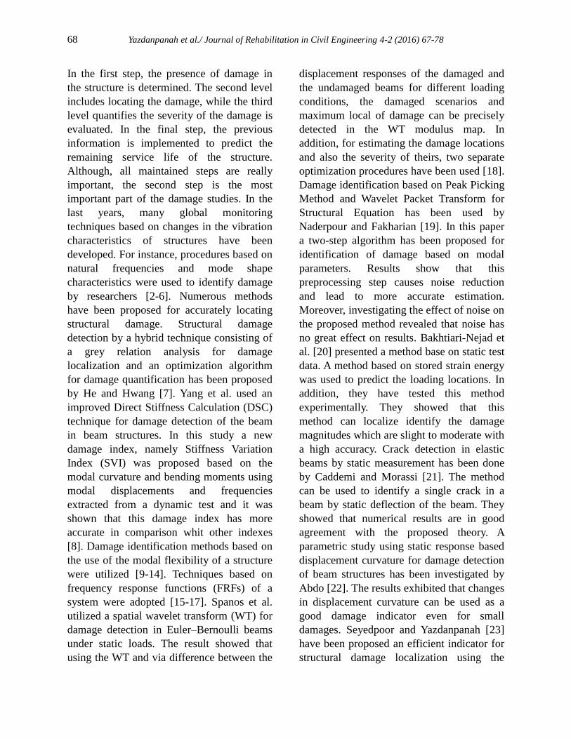
Journal of Rehabilitation in Civil Engineering 4-2 (2016) 67-78 journal homepage: http://civiljournal.semnan.ac.ir/ Embedded Crack Identification in Beam-Column Structures under Axial Load Using an Efficient Static Data Based Indicator O. Yazdanpanah 1 , R.A. Izadifard 2* and M. Abdi Moghadam 1 1. Ph.D. Student, Faculty of Engineering, Imam Khomeini International University, Qazvin, Iran 2. Assistant Professor, Faculty of Engineering, Imam Khomeini International University, Qazvin, Iran * Corresponding author: [email protected] ARTICLE INFO ABSTRACT Article history: Received: 02 January 2017 Accepted: 14 February 2017 A triangular model base on an investigation which has done by Sinha et al. has been developed for evaluating embedded crack localization in beam-column structures. In the assessment of this member’s behavior, the effects of displacement slope are necessary. In order to propose a crack localization method for embedded crack, an efficient static data based indicator is proposed for this crack in Euler- Bernoulli beam-columns under axial load effect. A finite element procedure is implemented for calculating the Static responses. Then, base on a central finite difference method, the slope and curvatures of horizontal displacements are evaluated. For this purpose, a simply supported beam- column and a two-span beam-column are considered and two different scenarios base on the damage of one element (single damage) and multiple elements (multiple damages) by considering the noise have been assessed. The numerical results have shown that this crack localization method has considerable accurate. Keywords: Crack modeling, Embedded crack detection, Beam-column structure, Axial load, Static responses. 1. Introduction The recent decades have experienced a rise in the importance of damage detection. Nearly all of the structures are at the expose of local damage during their lifetime. The total age of the structure, if the local damage can be detected and rehabilitated in an appropriate time, is more likely to rise. Health monitoring and structural damage identification, therefore, is a vital topic in structural engineering. When detecting and repairing the damage of elements, engineers can improve the safety of the whole structure and they will prevent catastrophic dangers. During the last years, many approaches have been introduced to determine the location and extent of the eventual damage in the structural systems. Structural damage detection consists of four different levels [1].
Transcript of Embedded Crack Identification in Beam-Column Structures ...
Journal of Rehabilitation in Civil Engineering 4-2 (2016) 67-78
journal homepage: http://civiljournal.semnan.ac.ir/
Embedded Crack Identification in Beam-Column
Structures under Axial Load Using an Efficient Static
Data Based Indicator
O. Yazdanpanah1, R.A. Izadifard
2* and M. Abdi Moghadam
1
1. Ph.D. Student, Faculty of Engineering, Imam Khomeini International University, Qazvin, Iran
2. Assistant Professor, Faculty of Engineering, Imam Khomeini International University, Qazvin, Iran
*
Corresponding author: [email protected]
ARTICLE INFO
ABSTRACT
Article history:
Received: 02 January 2017
Accepted: 14 February 2017
A triangular model base on an investigation which has done
by Sinha et al. has been developed for evaluating embedded
crack localization in beam-column structures. In the
assessment of this member’s behavior, the effects of
displacement slope are necessary. In order to propose a crack
localization method for embedded crack, an efficient static
data based indicator is proposed for this crack in Euler-
Bernoulli beam-columns under axial load effect. A finite
element procedure is implemented for calculating the Static
responses. Then, base on a central finite difference method,
the slope and curvatures of horizontal displacements are
evaluated. For this purpose, a simply supported beam-
column and a two-span beam-column are considered and two
different scenarios base on the damage of one element
(single damage) and multiple elements (multiple damages)
by considering the noise have been assessed. The numerical
results have shown that this crack localization method has
considerable accurate.
Keywords:
Crack modeling,
Embedded crack detection,
Beam-column structure,
Axial load,
Static responses.
1. Introduction
The recent decades have experienced a rise in
the importance of damage detection. Nearly
all of the structures are at the expose of local
damage during their lifetime. The total age of
the structure, if the local damage can be
detected and rehabilitated in an appropriate
time, is more likely to rise. Health
monitoring and structural damage
identification, therefore, is a vital topic in
structural engineering. When detecting and
repairing the damage of elements, engineers
can improve the safety of the whole structure
and they will prevent catastrophic dangers.
During the last years, many approaches have
been introduced to determine the location
and extent of the eventual damage in the
structural systems. Structural damage
detection consists of four different levels [1].
68 Yazdanpanah et al./ Journal of Rehabilitation in Civil Engineering 4-2 (2016) 67-78
In the first step, the presence of damage in
the structure is determined. The second level
includes locating the damage, while the third
level quantifies the severity of the damage is
evaluated. In the final step, the previous
information is implemented to predict the
remaining service life of the structure.
Although, all maintained steps are really
important, the second step is the most
important part of the damage studies. In the
last years, many global monitoring
techniques based on changes in the vibration
characteristics of structures have been
developed. For instance, procedures based on
natural frequencies and mode shape
characteristics were used to identify damage
by researchers [2-6]. Numerous methods
have been proposed for accurately locating
structural damage. Structural damage
detection by a hybrid technique consisting of
a grey relation analysis for damage
localization and an optimization algorithm
for damage quantification has been proposed
by He and Hwang [7]. Yang et al. used an
improved Direct Stiffness Calculation (DSC)
technique for damage detection of the beam
in beam structures. In this study a new
damage index, namely Stiffness Variation
Index (SVI) was proposed based on the
modal curvature and bending moments using
modal displacements and frequencies
extracted from a dynamic test and it was
shown that this damage index has more
accurate in comparison whit other indexes
[8]. Damage identification methods based on
the use of the modal flexibility of a structure
were utilized [9-14]. Techniques based on
frequency response functions (FRFs) of a
system were adopted [15-17]. Spanos et al.
utilized a spatial wavelet transform (WT) for
damage detection in Euler–Bernoulli beams
under static loads. The result showed that
using the WT and via difference between the
displacement responses of the damaged and
the undamaged beams for different loading
conditions, the damaged scenarios and
maximum local of damage can be precisely
detected in the WT modulus map. In
addition, for estimating the damage locations
and also the severity of theirs, two separate
optimization procedures have been used [18].
Damage identification based on Peak Picking
Method and Wavelet Packet Transform for
Structural Equation has been used by
Naderpour and Fakharian [19]. In this paper
a two-step algorithm has been proposed for
identification of damage based on modal
parameters. Results show that this
preprocessing step causes noise reduction
and lead to more accurate estimation.
Moreover, investigating the effect of noise on
the proposed method revealed that noise has
no great effect on results. Bakhtiari-Nejad et
al. [20] presented a method base on static test
data. A method based on stored strain energy
was used to predict the loading locations. In
addition, they have tested this method
experimentally. They showed that this
method can localize identify the damage
magnitudes which are slight to moderate with
a high accuracy. Crack detection in elastic
beams by static measurement has been done
by Caddemi and Morassi [21]. The method
can be used to identify a single crack in a
beam by static deflection of the beam. They
showed that numerical results are in good
agreement with the proposed theory. A
parametric study using static response based
displacement curvature for damage detection
of beam structures has been investigated by
Abdo [22]. The results exhibited that changes
in displacement curvature can be used as a
good damage indicator even for small
damages. Seyedpoor and Yazdanpanah [23]
have been proposed an efficient indicator for
structural damage localization using the

Yazdanpanah et al./ Journal of Rehabilitation in Civil Engineering 4-2 (2016) 67-78 69
change of strain energy based on noisy static
data (SSEBI).The acquired results crystal
clearly showed that the proposed indicator
could precisely locate the damaged elements.
The previous research works did not
investigate a beam column element under
axial load effects, and they did not consider
embedded crack; the main purpose of this
study, therefore, is the investigation and
detection the embedded cracks in beam
columns elements under axial load effects.
For this aim, an efficient damage indicator is
extended to estimate the embedded crack
locations in beam-column structures
proposing by the author for beam-like
structures (Yazdanpanah et al. [24]).
Numerical results demonstrate that the
proposed index can well determine the
locations of single and multiple embedded
damage cases whit different characteristics.
2. Embedded damage (crack)
modeling in beam-column
In this study, it is assumed that damage
occurs by a transverse surface crack located
at xcr from the left end of a beam-column as
shown in Fig. 1. For crack modeling, a fully
open transverse surface crack model,
illuminated by Sinha et al. [25], is adopted.
The effect of the crack on the mass is small
and can be neglected. The crack only leads to
local stiffness reduction in a specified length
adjacent to the crack. It is assumed that the
reduction of stiffness due to the crack is
inside one element. Considering one cracked
element as shown in Fig. 2, the flexural
rigidity EI of the cracked element varies
linearly from the cracked position towards
both sides in an effective length lc. The
stiffness matrix of the damaged element can
be represented as:
e e
crack u cjK K K (1)
Fig. 1. A simply supported beam-column having a
crack located at xcr from the left end
Fig. 2. Variation of EI due to the crack in an element
with length le
Where e
uK represents the element stiffness
matrix of the intact element; cjK is the
stiffness reduction on the intact element
stiffness matrix due to the jth
crack.
According to Euler–Bernoulli beam-column
element, the element stiffness matrix of the
intact beam-column is expressed as [26]:
0 0 0 0
(1 ) (1 )0 0
(1 ) (1 )0 0
0 0 0 0
(1 ) (1 )0 0
(1 ) (1 )0 0
e e
e e
e ee
u
e e
e e
e e
EA EA
L L
k c k cq q
L L
k c k ck kc
L LK
EA EA
L L
k c k cq q
L L
k c k ckc k
L L
(2)
70 Yazdanpanah et al./ Journal of Rehabilitation in Civil Engineering 4-2 (2016) 67-78
2
3
2
2
tan( )2( ) 1 ,
tan( ) ( )2 2
tan( )(1 ) ( ) 2 ,
2tan( ) ( )
2 2
( ) ( ) cos ( ) 1,
2tan( ) ( )
2 2
( ) 1 ( ) cot ( )
2tan( ) ( )
2 2
e
e e
e
e
l
EIq l
l lL
l
k c EI l
l lL L
EI l l ec lkc
l lL
EI l l g lk
l lL
2
2
,
, c
c e
P EIl P
P L
(3)
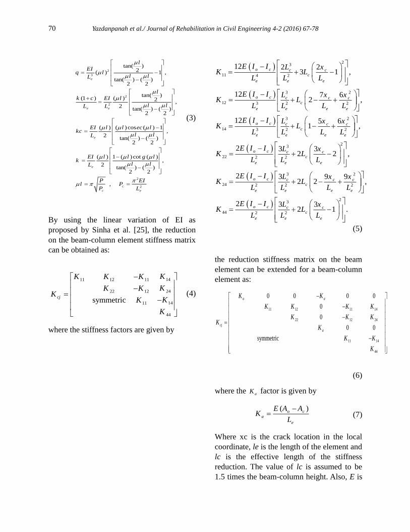
By using the linear variation of EI as
proposed by Sinha et al. [25], the reduction
on the beam-column element stiffness matrix
can be obtained as:
1411 12 11
2422 12
1411
44
symmetriccj
KK K K
KK KK
KK
K
(4)
where the stiffness factors are given by
23
11 4 2
3 2
12 3 2 2
3 2
14 3 2 2
23
22 2 2
12 2 23 1 ,
12 7 62 ,
12 5 61 ,
2 3 32 2
o c c cc
e e e
o c c c cc
e e e e
o c c c cc
e e e e
o c c cc
e e e
E I I L xK L
L L L
E I I L x xK L
L L L L
E I I L x xK L
L L L L
E I I L xK L
L L L
3 2
24 2 2 2
23
44 2 2
,
2 3 9 92 2 ,
2 3 32 1 .
o c c c cc
e e e e
o c c cc
e e e
E I I L x xK L
L L L L
E I I L xK L
L L L
(5)
the reduction stiffness matrix on the beam
element can be extended for a beam-column
element as:
11 12 11 14
22 12 24
11 14
44
0 0 0 0
0
0
0 0
symmetric
a a
cj
a
K K
K K K K
K K KK
K
K K
K
(6)
where the aK factor is given by
( )o c
a
e
E A AK
L
(7)
Where xc is the crack location in the local
coordinate, le is the length of the element and
lc is the effective length of the stiffness
reduction. The value of lc is assumed to be
1.5 times the beam-column height. Also, E is
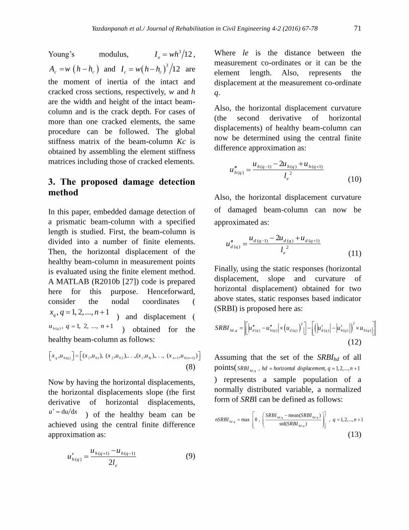
Yazdanpanah et al./ Journal of Rehabilitation in Civil Engineering 4-2 (2016) 67-78 71
Young’s modulus,
3 12oI wh ,
c cA w h h and 3
12c cI w h h are
the moment of inertia of the intact and
cracked cross sections, respectively, w and h
are the width and height of the intact beam-
column and is the crack depth. For cases of
more than one cracked elements, the same
procedure can be followed. The global
stiffness matrix of the beam-column Kc is
obtained by assembling the element stiffness
matrices including those of cracked elements.
3. The proposed damage detection
method
In this paper, embedded damage detection of
a prismatic beam-column with a specified
length is studied. First, the beam-column is
divided into a number of finite elements.
Then, the horizontal displacement of the
healthy beam-column in measurement points
is evaluated using the finite element method.
A MATLAB (R2010b [27]) code is prepared
here for this purpose. Henceforward,
consider the nodal coordinates (
1 ..., ,2 ,1 , nqxq ) and displacement (
( ) , 1, 2, ..., 1h qu q n ) obtained for the
healthy beam-column as follows:
( ) 1 1 2 2 i hi 1 ( 1), ( , ), ( , ),. . .,( , ),. . ., ( , )q h q h h n h nx u x u x u x u x u
(8)
Now by having the horizontal displacements,
the horizontal displacements slope (the first
derivative of horizontal displacements, du du x ) of the healthy beam can be
achieved using the central finite difference
approximation as:
( 1) ( 1)
( )2
h q h q
h q
e
u uu
l
(9)
Where le is the distance between the
measurement co-ordinates or it can be the
element length. Also, represents the
displacement at the measurement co-ordinate
q.
Also, the horizontal displacement curvature
(the second derivative of horizontal
displacements) of healthy beam-column can
now be determined using the central finite
difference approximation as:
( 1) ( ) ( 1)
( ) 2
2h q h q h q
h q
e
u u uu
l
(10)
Also, the horizontal displacement curvature
of damaged beam-column can now be
approximated as:
( 1) ( ) ( 1)
( ) 2
2d q d q d q
d q
e
u u uu
l
(11)
Finally, using the static responses (horizontal
displacement, slope and curvature of
horizontal displacement) obtained for two
above states, static responses based indicator
(SRBI) is proposed here as:
2 2
, ( ) ( ) ( ) ( ) ( ) ( )hd q d q h q q d q hd hq qSRBI u u u u uu
(12)
Assuming that the set of the SRBIhd of all
points(, , t, 1, 2,..., 1hd qSRBI hd horizontal displacemen q n
) represents a sample population of a
normally distributed variable, a normalized
form of SRBI can be defined as follows:
, ,
,
,
mean( )max 0 , , 1,2,..., 1
std( )
hd q hd q
hd q
hd q
SRBI SRBInSRBI q n
SRBI
(13)

72 Yazdanpanah et al./ Journal of Rehabilitation in Civil Engineering 4-2 (2016) 67-78
Where SRBIhd,q is defined by Eq. (12). Also,
mean (SRBIhd,q) and std (SRBIhd,q) represent
the mean and standard deviation of (
, , 1, 2,..., 1hd qSRBI q n ), respectively.
5. Numerical examples
In order to assess the efficiency of the
proposed method for embedded damage
detection under axial load, an example
including a simply supported beam-column is
considered. Various scenarios together with
noise effect are studied.
5.1 Example 1: a simply supported beam-
column
A simply supported beam-column with span
L=1 (m) shown in Fig. 3 is selected as the
sample. The beam-column has a cross-
section with dimensions of 0.04×0.05 m.
Modulus of elasticity is 7 22.1 10 /E ton m .
As shown in Table 1, for assessment of the
method, fifteen different damage scenarios
are considered. The first ten scenarios (cases
1-10), consist of a single damage under axial
load. The twelfth-fifteenth scenarios (cases
12-15), include multiple damage cases with
different intensity. Measurement noise cannot
be avoided. Hence, the effect of noise is
considered to perturb the responses of the
damaged structure. In this example, 3% noise
is assumed in scenarios 11 and 13,
respectively.
fig. 3. (a) Geometry of the simply supported beam-
column (b) Cross-section of the beam-column
Table 1. Fifteen different damage scenarios induced
in simply supported beam-column
Case Element
number
Damage
ratio* Pa
(ton)
(axial)
noise
1 1 0.30 1 0
2 2 0.20 1 0
3 3 0.25 1 0
4 4 0.15 1 0
5 5 0. 30 1 0
6 6 0.10 1 0
7 7 0.15 1 0
8 8 0.20 1 0
9 9 0.25 1 0
10 10 0.10 1 0
11 8 0.25 1 0.03
12 3 & 8 0.30 & 0.15 1 0
13 3 & 8 0.30 & 0.15 1 0.03
14 4 & 7 0.10 1 0
15 1 & 4 & 7
0.35 & 0.10
& 0.5
1 0
*Damage ratio is ch
h where hc is the crack depth
(a) Case-1
(b) Case-2

Yazdanpanah et al./ Journal of Rehabilitation in Civil Engineering 4-2 (2016) 67-78 73
(c) Case-3
(d) Case-4
Fig. 4. Damage identification of simply supported
beam-column for cases 1-4
(e) Case-5
(f) Case-6
(g) Case-7
(h) Case-8
Fig. 4. Damage identification of simply supported
beam-column for cases 5-8
(i) Case-9
(j) Case-10

74 Yazdanpanah et al./ Journal of Rehabilitation in Civil Engineering 4-2 (2016) 67-78
(k) Case-11
(l) Case-12
Fig. 4. Damage identification of simply supported
beam-column for cases 9-12
(m) Case-13
(n) Case-14
(o) Case-15
Fig. 4. Damage identification of simply supported
beam-column for cases 13-15
Damage identification charts of the simply
supported beam-column for cases 1 to 15
listed in Table 1 have been shown in Fig. 4,
respectively. As shown in the figures, the
value of nSRBIhd is further in the vicinity of
some elements that indicate damage occurs
in these elements. As can be observed in the
figures, the efficiency of the proposed
indicator for embedded damage localization
is high. Moreover, the effect of noise is
considered here by perturbing the responses
of the damaged structure. In this example,
3% noise is assumed in cases 11 and 13.
Figs. 4 (k) and 4 (m) show damage
identification charts for the damage scenarios
11 and 13 considering 3% noise. The
obtained results are showed a good match
between both scenarios with and without

Yazdanpanah et al./ Journal of Rehabilitation in Civil Engineering 4-2 (2016) 67-78 75
noise and there are reasonable correlations
between ones. In other words, the noise has a
negligible effect on the performance of
nSRBIhd.
5.2 Example 2: a two-span beam-column
An indeterminate beam-column with two
spans with span L=1 (m) shown in Fig. 5 is
considered as the second example. The
beam-column has a cross-section with
dimensions of 0.04×0.05 m. Modulus of
elasticity is 7 22.1 10 /E ton m
. As shown
in Table 2, for assessment of the method,
three different damage scenarios are
considered. The effect of noise is considered
to perturb the responses of damaged
structure. In this example, 3% noise is
assumed in scenarios 3.
Fig. 5. (a) Geometry of the two-span continuous
beam-column. (b) Cross-section of the beam-column
Table 2. Three different damage scenarios induced
in two-span continuous beam-column
Case Element
number
Damage
ratio*
Pa
(ton)
(axial)
noise
1 2 0.30 1 0
2 4 0.20 1 0
3 3 & 8 0.30 & 0.15 1 0.03
*Damage ratio is where hc is the crack depth
(a) Case-1
(b) Case-2
(c) Case-3
Fig. 6. Damage identification of two-span continuous
beam -column for cases 1-3
Damage identification charts of the two
spans beam-column for cases 1 to 3 listed in
Table 2 have been shown in Fig. 5,
respectively. As can be observed in the
figures, the proposed indicator is capable of
identifying all damage cases correctly
ch
h

76 Yazdanpanah et al./ Journal of Rehabilitation in Civil Engineering 4-2 (2016) 67-78
6. Conclusions
In this paper, the embedded cracks
identification in beam columns elements
under axial load effects has been
investigated. A damaged indicator proposed
for modal analysis (by the authors) has been
extended for static data (nSRBI). In order to
be sure about the accuracy of the proposed
damage detection method, some illustrative
damaged scenarios, including different
characteristics which may affect the
efficiency of the damage indicators, have
been studied with considering a simply
supported and two spans beam-column as a
test example. The nSRBI is sensitive to the
stiffness reduction (moments of inertia) and
as in the identification charts has been
presented, the proposed indicator could
identify all damage scenarios properly.
Moreover, measurement noise has a
negligible effect on the efficiency of the
proposed method for damage assessment.
References
[1] Rytter, A. (1993), “Vibration Based
Inspection of Civil Engineering Structures”.
Ph.D. Thesis, Aalborg University, Denmark.
[2] Cawley, P., Adams, R.D. (1979), “The
location of defects in structures from
measurements of natural frequency”, The
Journal of Strain Analysis for Engineering
Design, Vol.14(2), pp.49-57.
[3] Koh, B.H., Dyke, S.J. (2007), “Structural
health monitoring for flexible bridge
structures using correlation and sensitivity of
modal data”, Computers & Structures,
Vol.85(3-4), pp.117-130.
[4] Messina, A., Jones, I.A., Williams, E.J.
(1992), “Damage detection and localization
using natural frequency changes”,
Proceedings of the Conference on
Identification in Engineering System,
Cambridge, UK, Vol.1, pp.67-76.
[5] Doebling, S.W., Farrar, C.R., Prime,
M.B., Shevits, D.W. (1996), “Damage
identification and health monitoring of
structural and mechanical systems from
changes in their vibration characteristics: A
literature review”, Los Alamos National
Laboratory, USA, Vol.1, pp.1–136.
[6] Abdel Wahab, M.M., De Roeck, G.
(1999), “Damage detection in bridges using
modal curvatures: application to a real
damage scenario”, Journal of Sound and
Vibration, Vol.226(2), pp.217–235.
[7] Rong-Song He. R-S., Hwang S-F. (2007).
“Damage detection by a hybrid real-
parameter genetic algorithm under the
assistance of grey relation analysis”,
Engineering Applications of Artificial
Intelligence, Vol. 20 (7), pp. 980–992.
[8] Yang, Y., Liu, H., Mosalam, K.M.,
Huang, S. (2013). “An improved direct
stiffness calculation method for damage
detection of beam structures”. Structural
Control and Health Monitoring, Vol.20 (5),
pp.835-851.
[9] Nobahari, M., Seyedpoor, S.M. (2013),
“An efficient method for structural damage
localization based on the concepts of
flexibility matrix and strain energy of a
structure”, Structural Engineering and
Mechanics, Vol.46(2), pp.231-244.
[10] Pandey, A.K., Biswas, M. (1994),
“Damage detection in structures using
changes in flexibility”, Journal of Sound and
Vibration, Vol.169(1), pp.3–17.
Yazdanpanah et al./ Journal of Rehabilitation in Civil Engineering 4-2 (2016) 67-78 77
[11] Seyedpoor, S.M., Montazer, M. (2013),
“A damage identification method for truss
structures using a flexibility-based damage
probability index and differential evolution
algorithm”, Inverse Problems in Science and
Engineering, Vol.24(8), pp.1303-1322.
[12] Jaishi, B., Ren, W.X.. (2006). “Damage
detection by finite element model updating
using modal flexibility residual”. Journal of
Sound and Vibration. Vol. 290, pp.369–387.
[13] Miguel, L.F.F., Miguel, L.F.F., Riera,
J.D., Menezes, R.C.R. (2007). “Damage
detection in truss structures using a flexibility
based approach with noise influence
consideration”. Structural Engineering and
Mechanics, Vol.27, pp.625–638.
[14] Li, J., Wu, B., Zeng, Q.C., Lim, C.W.
(2010). “A generalized flexibility matrix
based approach for structural damage
detection”. Journal of Sound and Vibration,
Vol.329, pp.4583–4587.
[15] Wang, Z., Lin, R., Lim, M. (1997).
“Structural damage detection using measured
FRF data”. Computer Methods in Applied
Mechanics and Engineering,Vol.147, pp.187–
197.
[16] Huang, Q., Xu, Y.L., Li, J.C., Su, Z.Q.,
Liu, H.J. (2012). “Structural damage
detection of controlled building structures
using frequency response functions”. Journal
of Sound and Vibration, Vol. 331, pp.3476–
3492.
[17] Z. Wang, R. Lin, M. Lim (1997).
“Structural damage detection using measured
FRF data”. Computer Methods in Applied
Mechanics and Engineering, Vol.147,
pp.187–197.
[18] Spanos, P. D., Giuseppe F., Adolfo S.,
Massimiliano P. (2006). “Damage detection
in Euler–Bernoulli beams via spatial wavelet
analysis”, Structural Control and Health
Monitoring, Vol.13(1), pp.472-487.
[19] Naderpour H., Fakharian P. (2016). “A
synthesis of peak picking method and
wavelet packet transform for structural modal
identification”. KSCE Journal of Civil
Engineering, Vol. 20 (7), pp. 2859–2867.
doi:10.1007/s12205-016-0523-4.
[20] Bakhtiari-Nejad, F., A. Rahai,
Esfandiari, A. (2005). “A structural damage
detection method using static noisy data”.
Engineering Structures, Vol.27, pp.1784-
1793.
[21] Caddemi, S., Morassi, A. (2007). “Crack
detection in elastic beams by static
measurements”. International Journal of
Solids and Structures, Vol.44, pp.5301–5315.
[22] Abdo, M.A.-B and Hori, M. (2002). “A
numerical study of structural damage
detection using changes in the rotation of
mode shapes”. Journal of Sound and
Vibration, Vol.251(2), pp.227–239.
[23] Seyedpoor, S.M., Yazdanpanah, O.
(2013). “An efficient indicator for structural
damage localization using the change of
strain energy based on static noisy data”.
Appl. Math. Modelling, Vol38(9-10),
pp.2661-2672.
[24] Yazdanpanah O., Seyedpoor S.M.,
Akbarzadeh Bengar H. (2015). “A new
damage detection indicator for beams based
on mode shape data”. Structural Engineering
and Mechanics, Vol. 53, pp.725-744.
[25] Sinha, J.K., Friswell, M.I., Edwards, S.
(2002). “Simplified models for the location
of cracks in beam structures using measured
vibration data”. Journal of Sound and
Vibration, Vol.251(1), pp.13–38.

78 Yazdanpanah et al./ Journal of Rehabilitation in Civil Engineering 4-2 (2016) 67-78
[26] Yoo, C.H., Lee, S.C. (2011). “Stability of
Structures: Principles and Applications”.
Butterworth-Heinemann, Burlington, MA,
USA, pp.171-179.
[27] MATLAB (R2010b), the language of
technical computing (software), Math Works
Inc.