Embedded Audio Sound Module - RS...
17
Uncontrolled Copy when printed or downloaded. Please refer to the 4D Systems website for the latest Revision of this document Embedded Audio-Sound Module SOMO-II Document Date: 21 st March 2014 Document Revision: 1.1 DATASHEET
Transcript of Embedded Audio Sound Module - RS...
Uncontrolled Copy when printed or downloaded. Please refer to the 4D Systems website for the latest Revision of this document
Embedded Audio-Sound Module SOMO-II
Document Date: 21st March 2014
Document Revision: 1.1 DATA
SH
EET
SOM
O-II
Em
bed
ded
Audio
-Sou
nd M
odul
e
Contents
1. Description ............................................................................................................................. 3
2. Features ................................................................................................................................. 3
3. Pin Configuration and Summary .............................................................................................. 4
4. Pin Description ....................................................................................................................... 5
Micro-controller Interface Pins .............................................................................................................. 5 4.1.
Key Interface Pins (Not ADKEYs) ............................................................................................................ 5 4.2.
Key Interface Pins (ADKEY’s) .................................................................................................................. 5 4.3.
Audio Output and Control Pins .............................................................................................................. 5 4.4.
System Pins ............................................................................................................................................ 5 4.5.
5. Operating Modes .................................................................................................................... 6
SERIAL MODE ......................................................................................................................................... 6 5.1.
SERIAL MODE – Example Connection Diagram ...................................................................................... 9 5.2.
KEY MODE ............................................................................................................................................ 10 5.3.
Connecting up the Resistors and Pushbuttons to the ADKEY inputs ................................................... 11 5.4.
KEY MODE - Example Connection Diagram .......................................................................................... 12 5.5.
6. Files & Folder Structure......................................................................................................... 13
7. Media – micro-SD and USB Flash ........................................................................................... 14
Micro-SD cards ..................................................................................................................................... 14 7.1.
USB Flash Drive .................................................................................................................................... 14 7.2.
8. Mechanical Dimensions ........................................................................................................ 14
9. Development and Support Tools ........................................................................................... 14
Interfacing 4D Systems Display Modules ............................................................................................. 14 9.1.
10. Optional Connections ......................................................................................................... 15
USB Socket for USB Flash Drive .......................................................................................................... 15 10.1.
11. Specifications and Ratings ................................................................................................... 16
12. Legal Notice ........................................................................................................................ 17
13. Contact Information............................................................................................................ 17
4D SYSTEMS SOMO-II
© 2014 4D SYSTEMS Page 3 of 17 www.4dsystems.com.au
SOM
O-II
Em
bed
ded
Audio
-Sou
nd M
odul
e
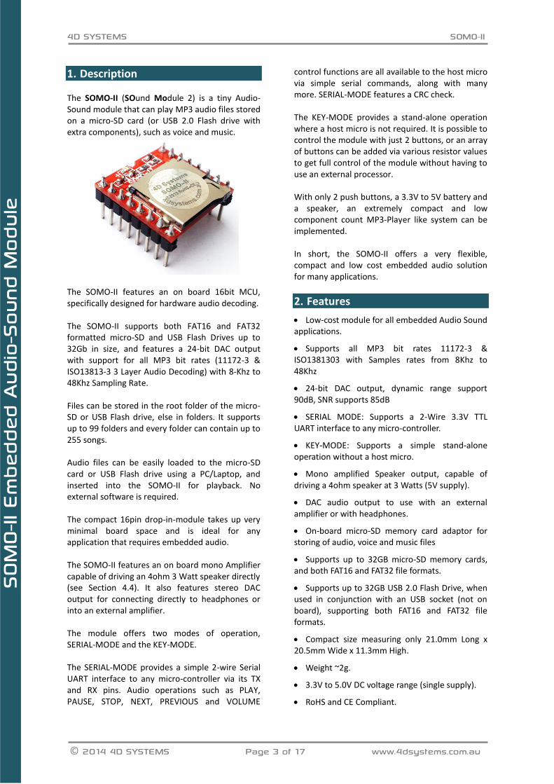
1. Description The SOMO-II (SOund Module 2) is a tiny Audio-Sound module that can play MP3 audio files stored on a micro-SD card (or USB 2.0 Flash drive with extra components), such as voice and music.
The SOMO-II features an on board 16bit MCU, specifically designed for hardware audio decoding. The SOMO-II supports both FAT16 and FAT32 formatted micro-SD and USB Flash Drives up to 32Gb in size, and features a 24-bit DAC output with support for all MP3 bit rates (11172-3 & ISO13813-3 3 Layer Audio Decoding) with 8-Khz to 48Khz Sampling Rate. Files can be stored in the root folder of the micro-SD or USB Flash drive, else in folders. It supports up to 99 folders and every folder can contain up to 255 songs. Audio files can be easily loaded to the micro-SD card or USB Flash drive using a PC/Laptop, and inserted into the SOMO-II for playback. No external software is required. The compact 16pin drop-in-module takes up very minimal board space and is ideal for any application that requires embedded audio. The SOMO-II features an on board mono Amplifier capable of driving an 4ohm 3 Watt speaker directly (see Section 4.4). It also features stereo DAC output for connecting directly to headphones or into an external amplifier. The module offers two modes of operation, SERIAL-MODE and the KEY-MODE. The SERIAL-MODE provides a simple 2-wire Serial UART interface to any micro-controller via its TX and RX pins. Audio operations such as PLAY, PAUSE, STOP, NEXT, PREVIOUS and VOLUME
control functions are all available to the host micro via simple serial commands, along with many more. SERIAL-MODE features a CRC check. The KEY-MODE provides a stand-alone operation where a host micro is not required. It is possible to control the module with just 2 buttons, or an array of buttons can be added via various resistor values to get full control of the module without having to use an external processor. With only 2 push buttons, a 3.3V to 5V battery and a speaker, an extremely compact and low component count MP3-Player like system can be implemented. In short, the SOMO-II offers a very flexible, compact and low cost embedded audio solution for many applications.
2. Features
Low-cost module for all embedded Audio Sound applications.
Supports all MP3 bit rates 11172-3 & ISO1381303 with Samples rates from 8Khz to 48Khz
24-bit DAC output, dynamic range support 90dB, SNR supports 85dB
SERIAL MODE: Supports a 2-Wire 3.3V TTL UART interface to any micro-controller.
KEY-MODE: Supports a simple stand-alone operation without a host micro.
Mono amplified Speaker output, capable of driving a 4ohm speaker at 3 Watts (5V supply).
DAC audio output to use with an external amplifier or with headphones.
On-board micro-SD memory card adaptor for storing of audio, voice and music files
Supports up to 32GB micro-SD memory cards, and both FAT16 and FAT32 file formats.
Supports up to 32GB USB 2.0 Flash Drive, when used in conjunction with an USB socket (not on board), supporting both FAT16 and FAT32 file formats.
Compact size measuring only 21.0mm Long x 20.5mm Wide x 11.3mm High.
Weight ~2g.
3.3V to 5.0V DC voltage range (single supply).
RoHS and CE Compliant.

4D SYSTEMS SOMO-II
© 2014 4D SYSTEMS Page 4 of 17 www.4dsystems.com.au
SOM
O-II
Em
bed
ded
Audio
-Sou
nd M
odul
e
3. Pin Configuration and Summary
SOMO-14D Pin Outs Pin Symbol I/O Description
1 USB+ I/O USB+ Signal, designed to be connected directly to the USB+ pin of an external USB socket, to then connect to a USB Flash drive
2 USB- I/O USB- Signal, to be used in conjunction with USB+
3 NEXT/VOL+ I Next Song (Song will start playing if currently stopped) when pressed. When held, the volume of the SOMO-II will ramp up.
4 PREV/VOL- I Previous Song (Song will start playing if currently stopped) when pressed. When held, the volume of the SOMO-II will ramp down.
5 ADKEY1 I Push button array input 1. Please refer to the ADKEY section for more information.
6 ADKEY2 I Push button array input 2. Please refer to the ADKEY section for more information.
7 GND P Power Ground. Connect to GND
8 BUSY O Playing indicator, can be used to trigger an external amplifier. Low indicates Audio output is occurring. High indicates no Audio output.
9 VCC P Power Input, 3.3V to 5.0V.
10 GND P Power Ground. Connect to GND
11 RX I 3.3V TTL UART Serial Data Input. Used for SERIAL-MODE
12 TX O 3.3V TTL UART Serial Data Output. Used for SERIAL-MODE
13 DAC_R O Right Channel Audio Output, capable of driving headphones directly, or connecting to an external amplifier
14 DAC_L O Left Channel Audio Output, capable of driving headphones directly, or connecting to an external amplifier
15 SPK+ O Speaker +ve output from on board Mono Amplifier, capable of driving a 4ohm 3W Speaker if VCC is 5V.
16 SPK- O Speaker -ve output from on board Mono Amplifier.
I = Input, O = Output, P = Power
USB+
USB-
NEXT/VOL+
PREV/VOL-
ADKEY1
ADKEY2
GND
BUSY
SPK-
SPK+
DAC_L
DAC_R
TX
RX
GND
VCC
4D SYSTEMS SOMO-II
© 2014 4D SYSTEMS Page 5 of 17 www.4dsystems.com.au
SOM
O-II
Em
bed
ded
Audio
-Sou
nd M
odul
e
4. Pin Description
This section describes in detail the hardware interface pins of the SOMO-II.
Micro-controller Interface Pins 4.1. RX pin 11 (TTL Serial UART Receive): This is the 3.3V TTL Serial UART Receive pin, compatible with 3.3V TTL level Logic, designed to be connected directly with a microcontroller or other TTL capable UART controller. Used in conjunction with the TX pin, the SOMO-II can be controlled using SERIAL-MODE by sending commands from the microcontroller rather than having to wire on any external buttons direct to the SOMO-II itself. Please refer to the SERIAL-MODE section for information about the commands. TX pin 12 (TTL Serial UART Transmit): This is the 3.3V TTL Serial UART Transmit pin, compatible with 3.3V TTL level Logic, designed to be connected directly with a microcontroller or other TTL capable UART controller. Used in conjunction with the RX pin, the SOMO-II can be controlled using SERIAL-MODE by sending commands from the microcontroller rather than having to wire on any external buttons direct to the SOMO-II itself. Please refer to the SERIAL-MODE section for information about the commands.
NOTE: For 5V systems, connect a series resistor (1K Ohms) on the RX line of the SOMO-II to the TX of the 5V micro-controller.
Key Interface Pins (Not ADKEYs) 4.2. NEXT/VOL+ pin 3 (Next Track/Volume up): Selects the Next Audio file from the micro-SD memory card or USB Flash drive (whichever is selected) when the pin is connected to GND momentarily. If the pin is held to GND then the Audio volume is ramped up. Active LOW triggered input. Connect this pin to a push-button in stand-alone KEY-MODE. PREV/VOL- pin 4 (Previous Track/Volume down): Selects the Previous Audio file from the micro-SD memory card or USB Flash drive (whichever is selected) when the pin is connected to GND momentarily. If the pin is held to GND then the Audio volume is ramped down. Active LOW
triggered input. Connect this pin to a push-button in stand-alone KEY-MODE.
Key Interface Pins (ADKEY’s) 4.3. ADKEY1, ADKEY2, pins 5, 6 (Array Keys): These pins provide a method to connect 10 push buttons up to each pin (up to 20 buttons total), to enable broad functionality of the SOMO-II without requiring the use of SERIAL-MODE.
Audio Output and Control Pins 4.4. SPK+, SPK- pins 15, 16 (Mono Speaker output): These pins provide a differential amplified output to a single speaker. Connect these pins to a 4/8/16/32ohm speaker, at a max of 3 Watts when powered from a 5V Supply. 8ohm 2.5W is recommended.
DAC_R, DAC_L pins 13, 14 (Stereo DAC output): These are the Left and Right audio outputs, capable of driving headphones directly or small speakers, or fed into an external amplifier.
BUSY pin 8 (Playing Indicator output): Playing Indicator, this pin shows if an audio file is currently being played (Low Output), or if no audio playback is currently occurring (High Output). The SOMO-II features an LED indicator on board which is connected to this pin, however it can also be connected to an external amplifier enable circuit, to disable the external amplifier when an audio file is not being played.
It can also be used to signal the host micro the end of the audio file in SERIAL-MODE, if required.
System Pins 4.5. GND pins 7, 10 (Module Ground): Module ground pins. One of more of these pins must be connected to ground. VCC pin 9 (Module Supply Voltage Input): Module supply voltage input pin. This pin must be connected to a regulated supply voltage in the range of 3.3 to 5.0 Volts DC. Nominal operating voltage is 4.3 Volts. USB+, USB- pins 1,2 (USB for Flash Drive): These pins provide a USB 2.0 interface to an external USB connector, to enable a USB Flash drive to be connected to the SOMO-II as a media source for MP3 audio files.

4D SYSTEMS SOMO-II
© 2014 4D SYSTEMS Page 6 of 17 www.4dsystems.com.au
SOM
O-II
Em
bed
ded
Audio
-Sou
nd M
odul
e
5. Operating Modes The SOMO module offers two modes of operation, SERIAL-MODE and KEY-MODE. This section describes both modes in detail.
SERIAL MODE 5.1. The SERIAL-MODE provides a simple 2-wire TTL Serial UART interface to any micro-controller capable of interfacing to a 3.3V or 5.0V (See Section 4.1) TLL Serial UART system that can be configured to output the simple protocol required to communicate with the SOMO-II. Baud Rate: 9600 bps Data bits: 1 Parity bit: none Flow Control: none The SOMO audio operations such as PLAY, PAUSE, STOP, NEXT, PREVIOUS and VOLUME etc are all available to the host micro-controller to control using a simple set of bytes sent to the SOMO-II, along with many more, which can be found under the Valid Commands listed below.
Command Format: The format of the serial commands are as follows
FORMAT: $S, CMD, Feedback, Para1, Para2, Checksum1, Checksum2, $0
$S Start Character $S is 0x7E in HEX Every command starts with this
CMD Command Code Every command has a unique command code, which determines the operation
Feedback Command Feedback Specifies whether feedback is required by the host microcontroller in reply to the command. 1 = Feedback, 0 = No Feedback
Para1 Parameter #1 First parameter of the specific Command Code
Para2 Parameter #2 Second parameter of the specific Command Code
Checksum1 Checksum #1 First byte of the checksum. Checksum calculation shown below.
Checksum2 Checksum #2 Second byte of the checksum. Checksum calculation shown below.
$0 End Character $0 is 0xEF in HEX Every command ends with this
Checksum Calculation:
The checksum is calculated using the following formula.
Checksum (2 bytes) = 0xFFFF – (CMD + Feedback + Para1 + Para2) + 1
Valid Commands:
All commands shown below have Feedback turned off so there will be no data sent from the SOMO-II after the command has been sent from the microcontroller (except for the Query commands which are requesting data).

4D SYSTEMS SOMO-II
© 2014 4D SYSTEMS Page 7 of 17 www.4dsystems.com.au
SOM
O-II
Em
bed
ded
Audio
-Sou
nd M
odul
e
Function Serial Command Description
NEXT 7E 01 00 00 00 FF FF EF
If no track is currently playing, issuing the NEXT command will start playing the first track copied to the media (see Section 6). If the SOMO-II is currently playing a song or has previously played a song, this will play the next song in the order copied on to the media.
PREVIOUS 7E 02 00 00 00 FF FE EF
If no track is currently playing, issuing the PREVIOUS command will start playing the last track copied to the media (see Section 6). If the SOMO-II is currently playing a song or has previously played a song, this will play the previous song in the order copied on to the media.
SPECIFY TRACK #
7E 03 00 00 01 FF FC EF 7E 03 00 00 02 FF FB EF 7E 03 00 00 0A FF F3 EF
Start playing the first track copied to the media. (See Section 6) This will start playing the second track copied to the media. This will start playing the tenth track copied to the media.
VOLUME + 7E 04 00 00 00 FF FC EF This will increase the volume by 1
VOLUME - 7E 05 00 00 00 FF FB EF This will decrease the volume by 1
VOLUME # 7E 06 00 00 1E FF DC EF 7E 06 00 00 05 FF F5 EF
This will set the volume to be 30 (30 is the Max) This will set the volume to be 5
SPECIFY EQ 7E 07 00 00 01 FF F8 EF 7E 07 00 00 04 FF F5 EF
This will set the EQ to pop This will set the EQ to classic (0/1/2/3/4/5 Normal, Pop, Rock, Jazz, Classic, Bass)
REPEAT A TRACK
7E 08 00 00 01 FF F7 EF 7E 08 00 00 02 FF F6 EF 7E 08 00 00 1F FF D9 EF
This will repeat the first track copied to the media. (See Section 6) This will repeat the second track copied to the media. This will repeat the thirty first track copied to the media.
PLAY SOURCE 7E 09 00 00 01 FF F6 EF 7E 09 00 00 02 FF F5 EF
This will set the SOMO-II to play from a USB Flash Drive This will set the SOMO-II to play from a micro-SD Card
SLEEP 7E 0A 00 00 00 FF F6 EF This will put the SOMO-II into a sleep state, which consumes low power. To get the SOMO-II out of sleep, you need to use a PLAY SOURCE command, followed by your next chosen command.
RESET 7E 0C 00 00 00 FF F4 EF This will reset the SOMO-II module, to be in its powered-on state
PLAY 7E 0D 00 00 00 FF F3 EF Play the audio track selected (if selected) else the first track copied on to the media (See Section 6)
PAUSE 7E 0E 00 00 00 FF F2 EF Pause the current playing audio Track. If PLAY command is then sent, the audio track will resume from where it was paused.
SPECIFY FOLDER &
TRACK
7E 0F 00 01 01 FF EF EF 7E 0F 00 01 0A FF E6 EF 7E 0F 00 63 FF FE 8F EF
This will start playing Folder 1 from Track 1. (See Section 6) This will start playing Folder 1 from Track 10. This will start playing Folder 99 from Track 255.
CONTINUOUS 7E 11 00 00 01 FF EE EF This will enable continuous mode (disable RANDOM TRACK and REPEAT CURRENT if previously enabled), which will play all songs on the memory card, one after the other. Start track with PLAY.
STOP 7E 16 00 00 00 FF EA EF Stop the current playing audio Track. If PLAY command is then sent, the audio track will start from the beginning.
RANDOM TRACK
7E 18 00 00 00 FF E8 EF This will enable Random Mode (disable CONTINUOUS and REPEAT CURRENT if previously enabled), which plays random tracks one after the other, continuously. Start track with PLAY.
REPEAT CURRENT
7E 19 00 00 00 FF E7 EF
This will enable the repeat play mode (disable CONTINUOUS and RANDOM TRACK if previously enabled), which repeats the currently playing track, so it will play over and over continuously. Track must be playing before this command is sent.

4D SYSTEMS SOMO-II
© 2014 4D SYSTEMS Page 8 of 17 www.4dsystems.com.au
SOM
O-II
Em
bed
ded
Audio
-Sou
nd M
odul
e
SINGLE PLAY 7E 19 00 00 01 FF E6 EF
This will disable CONTINUOUS, RANDOM TRACK or REPEAT CURRENT modes if previously enabled, which is how the module starts up by default. This will allow one song to play and then stop. Start track with PLAY.
QUERY VOLUME
7E 43 00 00 00 FF BD EF Query the current volume
QUERY EQ 7E 44 00 00 00 FF BC EF Query the current EQ Setting (0/1/2/3/4/5 Normal, Pop, Rock, Jazz, Classic, Bass)
QUERY TRACKS USB
7E 47 00 00 00 FF B9 EF Query the number of files present on the USB Flash Drive
QUERY TRACKS uSD
7E 48 00 00 00 FF B8 EF Query the number of files present on the
QUERY CURRENT
TRACK USB 7E 4B 00 00 00 FF B5 EF Query the current track playing from the USB Flash Drive
QUERY CURRENT
TRACK uSD 7E 4C 00 00 00 FF B4 EF Query the current track playing from the micro-SD Card
QUERY TRACKS FOLDER
7E 4E 00 00 01 FF B1 EF 7E 4E 00 00 0B FF A7 EF
This will return the number of tracks in Folder 1 (001) This will return the number of tracks in Folder 11 (011)
Successful command received by SOMO-II (Feedback Byte needs to be ON): If Feedback is required for successful receipt of a command, simply change the Feedback byte from 0x00 to 0x01, and a confirmation message will be sent from the SOMO-II after the command is sent and received.
Errors received from the SOMO-II: If a command is sent to the SOMO-II and the SOMO-II resulted in an error from that command, the following messages could be sent. These are sent on error regardless of if the feedback byte is enabled or disabled.
Other information received from SOMO-II: These commands are sent from the SOMO-II when certain events occur, and could come at various times.
Feedback Received Description
7E 41 00 00 00 FF BF EF Command Successfully Received
ERRORS Received Description
7E 40 00 00 01 FF BF EF Module is busy
7E 40 00 00 02 FF BE EF Module is currently in sleep mode
7E 40 00 00 03 FF BD EF Serial received an error
7E 40 00 00 04 FF BC EF Checksum error
7E 40 00 00 05 FF BB EF Beyond scope of specified file/folder
7E 40 00 00 06 FF BA EF Specified file/Folder not found
DATA Received Description
7E 3A 00 00 01 FF C5 EF USB Flash Drive Inserted. Sent every time a USD Flash drive is plugged in.
7E 3A 00 00 02 FF C4 EF micro-SD Card Inserted. Sent every time a micro-SD card is inserted.

4D SYSTEMS SOMO-II
© 2014 4D SYSTEMS Page 9 of 17 www.4dsystems.com.au
SOM
O-II
Em
bed
ded
Audio
-Sou
nd M
odul
e
SERIAL MODE – Example Connection Diagram 5.2.
This example schematic shows a simple Serial connection to an external Host such as a 3.3V Microcontroller. It also shows the connections for an external speaker.
7E 3B 00 00 01 FF C4 EF USB Flash Drive Removed. Sent every time a USD Flash drive is unplugged.
7E 3B 00 00 02 FF C3 EF
micro-SD Card Removed. Sent every time a micro-SD card is ejected. NOTE: when the card is ejected, multiple messages may be sent (ejected, inserted and ejected again). This is a side-effect of the type of micro-SD socket that is installed if the card is ejected slowly, ie holding in the card before releasing.
7E 3C 00 00 01 FF C3 EF 7E 3C 00 00 54 FF 70 EF
USB Flash Drive source, Finished playing Track 01 USB Flash Drive source, Finished playing Track 84 (0x54)
7E 3D 00 00 02 FF C1 EF 7E 3D 00 00 0A FF B9 EF
micro-SD Card source, Finished playing Track 02 micro-SD Card source, Finished playing Track 10 (0x0A)
7E 3F 00 00 00 FF C1 EF SOMO-II has just started up, No media detected
7E 3F 00 00 01 FF C0 EF SOMO-II has just started up, USB Flash Drive detected
7E 3F 00 00 02 FF BF EF SOMO-II has just started up, micro-SD Card detected
7E 3F 00 00 03 FF BE EF SOMO-II has just started up, Both micro-SD and USB Flash Drive detected
4D SYSTEMS SOMO-II
© 2014 4D SYSTEMS Page 10 of 17 www.4dsystems.com.au
SOM
O-II
Em
bed
ded
Audio
-Sou
nd M
odul
e
KEY MODE 5.3.
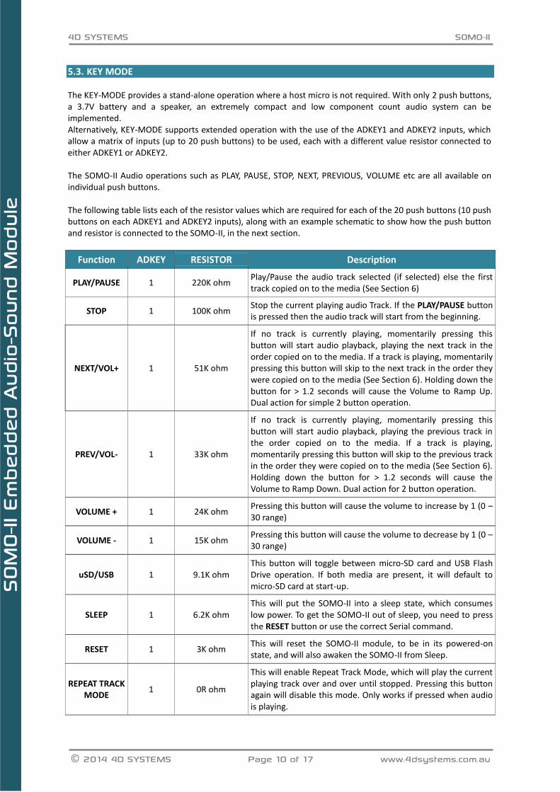
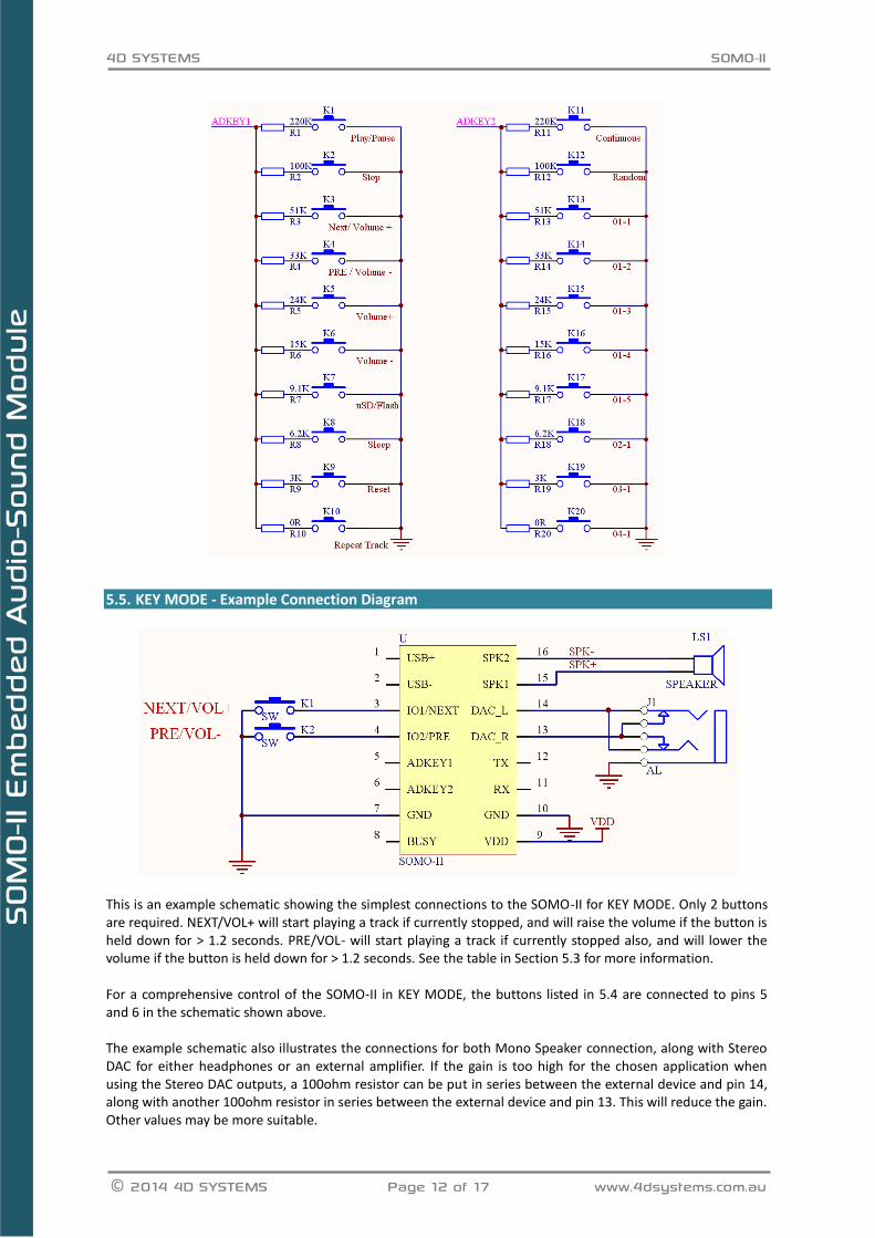
The KEY-MODE provides a stand-alone operation where a host micro is not required. With only 2 push buttons, a 3.7V battery and a speaker, an extremely compact and low component count audio system can be implemented. Alternatively, KEY-MODE supports extended operation with the use of the ADKEY1 and ADKEY2 inputs, which allow a matrix of inputs (up to 20 push buttons) to be used, each with a different value resistor connected to either ADKEY1 or ADKEY2. The SOMO-II Audio operations such as PLAY, PAUSE, STOP, NEXT, PREVIOUS, VOLUME etc are all available on individual push buttons. The following table lists each of the resistor values which are required for each of the 20 push buttons (10 push buttons on each ADKEY1 and ADKEY2 inputs), along with an example schematic to show how the push button and resistor is connected to the SOMO-II, in the next section.
Function ADKEY RESISTOR Description
PLAY/PAUSE 1 220K ohm Play/Pause the audio track selected (if selected) else the first track copied on to the media (See Section 6)
STOP 1 100K ohm Stop the current playing audio Track. If the PLAY/PAUSE button is pressed then the audio track will start from the beginning.
NEXT/VOL+ 1 51K ohm
If no track is currently playing, momentarily pressing this button will start audio playback, playing the next track in the order copied on to the media. If a track is playing, momentarily pressing this button will skip to the next track in the order they were copied on to the media (See Section 6). Holding down the button for > 1.2 seconds will cause the Volume to Ramp Up. Dual action for simple 2 button operation.
PREV/VOL- 1 33K ohm
If no track is currently playing, momentarily pressing this button will start audio playback, playing the previous track in the order copied on to the media. If a track is playing, momentarily pressing this button will skip to the previous track in the order they were copied on to the media (See Section 6). Holding down the button for > 1.2 seconds will cause the Volume to Ramp Down. Dual action for 2 button operation.
VOLUME + 1 24K ohm Pressing this button will cause the volume to increase by 1 (0 – 30 range)
VOLUME - 1 15K ohm Pressing this button will cause the volume to decrease by 1 (0 – 30 range)
uSD/USB 1 9.1K ohm This button will toggle between micro-SD card and USB Flash Drive operation. If both media are present, it will default to micro-SD card at start-up.
SLEEP 1 6.2K ohm This will put the SOMO-II into a sleep state, which consumes low power. To get the SOMO-II out of sleep, you need to press the RESET button or use the correct Serial command.
RESET 1 3K ohm This will reset the SOMO-II module, to be in its powered-on state, and will also awaken the SOMO-II from Sleep.
REPEAT TRACK MODE
1 0R ohm
This will enable Repeat Track Mode, which will play the current playing track over and over until stopped. Pressing this button again will disable this mode. Only works if pressed when audio is playing.

4D SYSTEMS SOMO-II
© 2014 4D SYSTEMS Page 11 of 17 www.4dsystems.com.au
SOM
O-II
Em
bed
ded
Audio
-Sou
nd M
odul
e
CONTINUOUS
MODE 2 220K ohm
This will enable Continuous Mode, which will play all the files on the media one after the other and stop when it reaches the last audio track. Pressing PLAY or NEXT once it has stopped, will start the process over. Default is for this mode to be off, which will just play a single track and then stop. Pressing this button again will disable this mode.
RANDOM TRACK MODE
2 100K ohm This will enable Random Mode, which will play a random track off the media, followed by another random track, continuously. Pressing this button again will disable this mode.
Track 1 Folder 1
2 51K ohm This will play Track 1 from Folder 1, as a quick method to jump to a specific audio file.
Track 1 Folder 2
2 33K ohm This will play Track 1 from Folder 2, as a quick method to jump to a specific audio file.
Track 1 Folder 3
2 24K ohm This will play Track 1 from Folder 3, as a quick method to jump to a specific audio file.
Track 1 Folder 4
2 15K ohm This will play Track 1 from Folder 4, as a quick method to jump to a specific audio file.
Track 1 Folder 5
2 9.1K ohm This will play Track 1 from Folder 5, as a quick method to jump to a specific audio file.
Track 2 Folder 1
2 6.2K ohm This will play Track 2 from Folder 1, as a quick method to jump to a specific audio file.
Track 3 Folder 1
2 3K ohm This will play Track 3 from Folder 1, as a quick method to jump to a specific audio file.
Track 4 Folder 1
2 0R ohm This will play Track 4 from Folder 1, as a quick method to jump to a specific audio file.
Connecting up the Resistors and Pushbuttons to the ADKEY inputs 5.4. The connection of the push buttons to the ADKEY’s is simple. Simply connect the resistor required to the ADKEY1 or ADKEY2 inputs of the SOMO-II module, and connect the other end of the resistor to one side of your push button. Connect the other side of your push button to GND. Each ADKEY will have up to 10 resistors coming off it, each with its own push button. Only the resistors and buttons required can be connected, it is not necessary to connect all the resistors and buttons. The specific resistor value must be used however to control the specific function, this cannot be changed. Please refer to image on following page.
4D SYSTEMS SOMO-II
© 2014 4D SYSTEMS Page 12 of 17 www.4dsystems.com.au
SOM
O-II
Em
bed
ded
Audio
-Sou
nd M
odul
e
KEY MODE - Example Connection Diagram 5.5.
This is an example schematic showing the simplest connections to the SOMO-II for KEY MODE. Only 2 buttons are required. NEXT/VOL+ will start playing a track if currently stopped, and will raise the volume if the button is held down for > 1.2 seconds. PRE/VOL- will start playing a track if currently stopped also, and will lower the volume if the button is held down for > 1.2 seconds. See the table in Section 5.3 for more information. For a comprehensive control of the SOMO-II in KEY MODE, the buttons listed in 5.4 are connected to pins 5 and 6 in the schematic shown above. The example schematic also illustrates the connections for both Mono Speaker connection, along with Stereo DAC for either headphones or an external amplifier. If the gain is too high for the chosen application when using the Stereo DAC outputs, a 100ohm resistor can be put in series between the external device and pin 14, along with another 100ohm resistor in series between the external device and pin 13. This will reduce the gain. Other values may be more suitable.

4D SYSTEMS SOMO-II
© 2014 4D SYSTEMS Page 13 of 17 www.4dsystems.com.au
SOM
O-II
Em
bed
ded
Audio
-Sou
nd M
odul
e
6. Files & Folder Structure The SOMO-II is flexible how files are stored on the micro-SD or USB Flash drive media, however in order to have control over which files are played, it is important to follow some simple naming rules in order for the SOMO-II to play the specific file you intend it to play. The SOMO-II is capable of addressing up to 99 Folders, each with up to 255 songs. The SOMO-II is not capable of reading ID3 information from the MP3 files, so purely relies on the name of the file as the index (Primary method), or the order the files were copied onto the media (Secondary Method). While MP3 files can be named almost anything and they will play, in order to index the files so they can be picked on request using a specific serial command to select the folder/file using the Primary Method, the following must be observed: 001ABCDEFG.mp3 Where 001 refers to the track number from 1 (001) to 255 as the SOMO-II can address up to 255 songs in each folder, and ABCDEFG refers to any alphanumeric name of your choosing, where the total file name length can be up to 32 characters long (Operating System dependent), ending with an .mp3 extension.
The folder structure should then have the following naming convention: 01 Where 01 refers to a number from 01 to 99, as the SOMO-II can address up to 99 folders.
If songs are placed on the media and they may or may not follow the naming convention, then the songs can be played using the PLAY, NEXT, PREV commands or buttons, or using the SPECIFY TRACK # command, which uses the Secondary Method and plays based on the order the songs were copied on to the media, not by the name of the file itself. Songs can be in the root directory or in folders, however the SOMO-II will only care about the order they were copied (Secondary Method) on to the media and not the name or location of the files. The SPECIFY FOLDER & TRACK command however cannot be used if the naming convention has not been followed (Primary Method), as this relies on the formatting above to be observed. Note, when using the SPECIFY FOLDER & TRACK command, Folder and Track numbering is in HEX. So the Folders are 0x01 through 0x63 (1 to 99), and the Tracks are 0x01 through 0xFF (1 to 255). If the above formatting is observed, all commands will work correctly, so both Primary and Secondary methods are functional. It may be difficult to determine the order songs were copied onto the media, so the Secondary Method should only be used if the order is not critical or the copy order is known. The Primary Method should be used as the preferred method.

4D SYSTEMS SOMO-II
© 2014 4D SYSTEMS Page 14 of 17 www.4dsystems.com.au
SOM
O-II
Em
bed
ded
Audio
-Sou
nd M
odul
e
7. Media – micro-SD and USB Flash
Micro-SD cards 7.1.
The SOMO-II uses off the shelf micro-SD and microSD-HC memory cards with up to 32GB capacity, and compatible with both FAT16 and FA32 file formats. The formatting of the card can be done on any PC/Mac/Linux system with a card reader. Select the appropriate drive and choose the FAT16 or FAT32 file format, depending on the capacity of your micro-SD card. The card is now ready to be used in the SOMO-II.
NOTE: Certain brands of micro-SD memory cards may not work properly. This is evident by some files that may be skipped and not played by the SOMO-II.
USB Flash Drive 7.2. The SOMO-II is compatible with a range of USB Flash Drives, and has a USB 2.0 interface. It does however require an external USB socket to be installed and connected to the USB+, USB-, and GND pins of the SOMO-II. If the SOMO-II is not powered with 5.0V, then an external 5V supply will be required and connected to the USB socket, else the VCC from the SOMO-II can be connected to the USB socket if the SOMO-II is powered from 5.0V. Some USB Flash Drives may operate down to as low as 3.7V, however it is recommended to use 5V when using USB Flash Drives. The USB Flash Drive can be up to 32GB in capacity, and formatted with either FAT16 or FAT32, depending on the capacity of the card.
NOTE: Certain brands of USB Flash Drives may not work properly. This is evident by some files that may be skipped and not played by the SOMO-II.
8. Mechanical Dimensions
The height of the module is ~11.3mm
9. Development and Support Tools
Interfacing 4D Systems Display Modules 9.1.
4D Systems offers a wide range of Intelligent Display Modules which are perfectly suited to interface with the SOMO-II, to provide a front end GUI for users to interact with the SOMO-II.
While any of the 4D Systems Intelligent Display modules are capable of interfacing with the SOMO-II, ones which feature a Resistive or Capacitive touch screen would be the best choice, so no external buttons are required, and communications between the SOMO-II and the Display Module are over Serial, using SERIAL-MODE.
Perfectly suited modules would be the following:
uLCD-32PTU
uLCD-35DT
uLCD-43PT or uLCD-43PCT
uLCD-70DT
Please refer to the 4D Systems website (www.4dsystems.com.au) for information regarding these modules.
4D SYSTEMS SOMO-II
© 2014 4D SYSTEMS Page 15 of 17 www.4dsystems.com.au
SOM
O-II
Em
bed
ded
Audio
-Sou
nd M
odul
e
10. Optional Connections
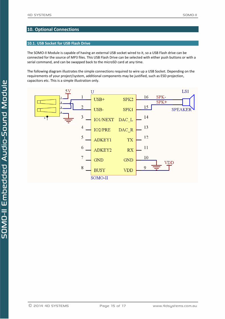
USB Socket for USB Flash Drive 10.1. The SOMO-II Module is capable of having an external USB socket wired to it, so a USB Flash drive can be connected for the source of MP3 files. This USB Flash Drive can be selected with either push buttons or with a serial command, and can be swapped back to the microSD card at any time. The following diagram illustrates the simple connections required to wire up a USB Socket. Depending on the requirements of your project/system, additional components may be justified, such as ESD projection, capacitors etc. This is a simple illustration only.

4D SYSTEMS SOMO-II
© 2014 4D SYSTEMS Page 16 of 17 www.4dsystems.com.au
SOM
O-II
Em
bed
ded
Audio
-Sou
nd M
odul
e
11. Specifications and Ratings
ABSOLUTE MAXIMUM RATINGS
Operating ambient temperature ................................................................................................... -0°C to +70°C
Voltage on VCC with respect to GND ................................................................................................ 3.2V to 5.5V
NOTE: Stresses above those listed here may cause permanent damage to the device. This is a stress rating only and functional operation of the device at those or any other conditions above those indicated in the recommended operation listings of this specification is not implied. Exposure to maximum rating conditions for extended periods may affect device reliability.
RECOMMENDED OPERATING CONDITIONS
Parameter Conditions Min Typ Max Units
Supply Voltage (VCC) 3.3 4.3 5.0 V
Operating Temperature 0 -- +70 °C
Input Low Voltage (VIL) All pins -0.3 -- 0.3*VCC V
Input High Voltage (VIH) All pins 0.7*VCC -- VCC+0.3 V
GLOBAL CHARACTERISTICS BASED ON OPERATING CONDITIONS
Parameter Conditions Min Typ Max Units
Supply Current (ICC) VCC = 5.0V, Audio Playing 30 -- 300 mA
Standby (Sleep) Current VCC = 5.0V 20 mA
Output Low Voltage (VOL) -- -- 0.33 V
Output High Voltage (VOH) 2.7 -- -- V
ORDERING INFORMATION
Order Code: SOMO-II
Package: 80mm x 120mm (ZIP Bag dimensions).
Packaging: Module sealed in antistatic ZIP bag.
4D SYSTEMS SOMO-II
© 2014 4D SYSTEMS Page 17 of 17 www.4dsystems.com.au
SOM
O-II
Em
bed
ded
Audio
-Sou
nd M
odul
e
12. Legal Notice Proprietary Information The information contained in this document is the property of 4D Systems Pty. Ltd. and may be the subject of patents pending or granted, and must not be copied or disclosed without prior written permission. 4D Systems endeavours to ensure that the information in this document is correct and fairly stated but does not accept liability for any error or omission. The development of 4D Systems products and services is continuous and published information may not be up to date. It is important to check the current position with 4D Systems. 4D Systems reserves the right to modify, update or makes changes to Specifications or written material without prior notice at any time. All trademarks belong to their respective owners and are recognised and acknowledged. Disclaimer of Warranties & Limitation of Liability 4D Systems makes no warranty, either expressed or implied with respect to any product, and specifically disclaims all other warranties, including, without limitation, warranties for merchantability, non-infringement and fitness for any particular purpose. Information contained in this publication regarding device applications and the like is provided only for your convenience and may be superseded by updates. It is your responsibility to ensure that your application meets with your specifications. In no event shall 4D Systems be liable to the buyer or to any third party for any indirect, incidental, special, consequential, punitive or exemplary damages (including without limitation lost profits, lost savings, or loss of business opportunity) arising out of or relating to any product or service provided or to be provided by 4D Systems, or the use or inability to use the same, even if 4D Systems has been advised of the possibility of such damages. 4D Systems products are not fault tolerant nor designed, manufactured or intended for use or resale as on line control equipment in hazardous environments requiring fail – safe performance, such as in the operation of nuclear facilities, aircraft navigation or communication systems, air traffic control, direct life support machines or weapons systems in which the failure of the product could lead directly to death, personal injury or severe physical or environmental damage (‘High Risk Activities’). 4D Systems and its suppliers specifically disclaim any expressed or implied warranty of fitness for High Risk Activities. Use of 4D Systems’ products and devices in 'High Risk Activities' and in any other application is entirely at the buyer’s risk, and the buyer agrees to defend, indemnify and hold harmless 4D Systems from any and all damages, claims, suits, or expenses resulting from such use. No licenses are conveyed, implicitly or otherwise, under any 4D Systems intellectual property rights.
13. Contact Information
For Technical Support: [email protected]
For Sales Support: [email protected]
Website: www.4dsystems.com.au
Copyright 4D Systems Pty. Ltd. 2000-2014.