EM3090 - Newland - Scanning made simple · 2017-08-24 · Do not disassemble the device or remove...
146
EM3090 OEM Scan Engine User Guide
Transcript of EM3090 - Newland - Scanning made simple · 2017-08-24 · Do not disassemble the device or remove...
EM3090OEM Scan EngineUser Guide

Disclaimer
© 2016 Fujian Newland Auto-ID Tech. Co., Ltd. All rights reserved.
Please read through the manual carefully before using the product and operate it according to the manual. It is advised that you should keep this manual for future reference.
Do not disassemble the device or remove the seal label from the device, doing so will void the product warranty provided by Fujian Newland Auto-ID Tech. Co., Ltd.
All pictures in this manual are for reference only and actual product may differ. Regarding to the product modification and update, Fujian Newland Auto-ID Tech. Co., Ltd. reserves the right to make changes to any software or hardware to improve reliability, function, or design at any time without notice. The information contained herein is subject to change without prior notice.
The products depicted in this manual may include software copyrighted by Fujian Newland Auto-ID Tech. Co., Ltd or third party. The user, corporation or individual, shall not duplicate, in whole or in part, distribute, modify, decompile, disassemble, decode, reverse engineer, rent, transfer or sublicense such software without prior written consent from the copyright holders.
This manual is copyrighted. No part of this publication may be reproduced, distributed or used in any form without written permission from Newland.
Fujian Newland Auto-ID Tech. Co., Ltd. reserves the right to make final interpretation of the statement above.

Revision History
Version Description Date
V1.0.0 Initial release. April 25, 2016
Table Of Contents
Revision History ............................................................................................................................................... -3-
Chapter 1 Getting Started .................................................................................................................................. 1
Introduction .............................................................................................................................................. 1
About This Guide ..................................................................................................................................... 1
Connecting EVK to PC ............................................................................................................................ 1
Barcode Scanning ................................................................................................................................... 1
Barcode Programming ............................................................................................................................. 1
Factory Defaults ....................................................................................................................................... 2
Custom Defaults ...................................................................................................................................... 2
Chapter 2 Communication Interfaces .............................................................................................................. 3
Power-Saving Mode ................................................................................................................................ 3
TTL-232 Interface .................................................................................................................................... 4
Baud Rate ......................................................................................................................................... 5
Parity Check ..................................................................................................................................... 6
Data Bit ............................................................................................................................................. 6
Data Bit & Parity Check .................................................................................................................... 7
Stop Bit ............................................................................................................................................. 7
USB Interface (Optional) ......................................................................................................................... 8
USB Enumeration ............................................................................................................................. 8
USB HID-KBW .................................................................................................................................. 8
Polling Rate ............................................................................................................................... 9
USB Country Keyboard Types ................................................................................................ 10
Beep on Unknown Character .................................................................................................. 12
Inter-Keystroke Delay .............................................................................................................. 12
Convert Case ........................................................................................................................... 13
Emulate ALT+Keypad ............................................................................................................. 14
Function Key Mapping ............................................................................................................. 15
Emulate Numeric Keypad........................................................................................................ 16
Code Page ............................................................................................................................... 16
USB COM Port Emulation .............................................................................................................. 17
USB HID-POS ................................................................................................................................ 17
Introduction .............................................................................................................................. 17
Access the Engine with Your Program ................................................................................... 18
Acquire Scanned Data ............................................................................................................ 18
Send Data to the Engine ......................................................................................................... 18
VID/PID .................................................................................................................................... 18
Chapter 3 Scan Mode ....................................................................................................................................... 20
Batch Mode ............................................................................................................................................ 20
Trigger Mode ......................................................................................................................................... 21
Decode Session Timeout ............................................................................................................... 21
Level Trigger/Pulse Trigger ............................................................................................................ 22
Auto Sleep ...................................................................................................................................... 22
Timeout between Decodes (Same Barcode) ................................................................................. 22
Sense Mode ........................................................................................................................................... 24
Decode Session Timeout ............................................................................................................... 24
Image Stabilization Timeout ........................................................................................................... 24
Continue after Good Read .............................................................................................................. 24
Timeout between Decodes (Same Barcode) ................................................................................. 25
Sensitivity ........................................................................................................................................ 26
Continuous Mode................................................................................................................................... 28
Decode Session Timeout ............................................................................................................... 28
Timeout between Decodes ............................................................................................................. 28
Timeout between Decodes (Same Barcode) ................................................................................. 29
Chapter 4 Scanning Preferences .................................................................................................................... 30
Introduction ............................................................................................................................................ 30
Decode Area .......................................................................................................................................... 30
Whole Area Decoding ..................................................................................................................... 30
Central Area Decoding ................................................................................................................... 30
Specify Central Area ............................................................................................................... 31
Chapter 5 Illumination & Aiming..................................................................................................................... 32
Illumination ............................................................................................................................................. 32
Aiming .................................................................................................................................................... 33
Chapter 6 Beep & LED Notifications .............................................................................................................. 34
Startup Beep .......................................................................................................................................... 34
Good Read Beep for Non-programming Barcode ................................................................................. 35
Beep Type....................................................................................................................................... 35
Beep Volume .................................................................................................................................. 36
Beep on Unknown Character ................................................................................................................ 36
Good Read Beep for Programming Barcode ........................................................................................ 37
Good Read LED .................................................................................................................................... 37
Transmit NGR Message ........................................................................................................................ 38
Edit NGR Message ......................................................................................................................... 38
Chapter 7 Prefix & Suffix ................................................................................................................................. 39
Global Settings ...................................................................................................................................... 40
Enable/Disable All Prefix/Suffix ...................................................................................................... 40
Prefix Sequences ............................................................................................................................ 40
Custom Prefix ........................................................................................................................................ 41
Enable/Disable Custom Prefix ........................................................................................................ 41
Set Custom Prefix ........................................................................................................................... 41
AIM ID Prefix .......................................................................................................................................... 42
Code ID Prefix ....................................................................................................................................... 42
Restore All Default Code IDs.......................................................................................................... 42
Modify Code ID ............................................................................................................................... 43
Custom Suffix ........................................................................................................................................ 46
Enable/Disable Custom Suffix ........................................................................................................ 46
Set Custom Suffix ........................................................................................................................... 46
Terminating Character Suffix ................................................................................................................. 47
Enable/Disable Terminating Character Suffix ................................................................................ 47
Set Terminating Character Suffix ................................................................................................... 48
Chapter 8 Symbologies ................................................................................................................................... 49
Global Settings ...................................................................................................................................... 49
Enable/Disable All Symbologies ..................................................................................................... 49
Enable/Disable 1D Symbologies .................................................................................................... 49
Enable/Disable 2D Symbologies .................................................................................................... 49
Video Reverse ................................................................................................................................ 50
1D Symbologies ..................................................................................................................................... 51
Code 128 ........................................................................................................................................ 51
Restore Factory Defaults......................................................................................................... 51
Enable/Disable Code 128........................................................................................................ 51
Set Length Range for Code 128 ............................................................................................. 51
GS1-128 (UCC/EAN-128) .............................................................................................................. 52
Restore Factory Defaults......................................................................................................... 52
Enable/Disable GS1-128 ......................................................................................................... 52
Set Length Range for GS1-128 ............................................................................................... 52
AIM-128 .......................................................................................................................................... 53
Restore Factory Defaults......................................................................................................... 53
Enable/Disable AIM-128.......................................................................................................... 53
Set Length Range for AIM-128 ............................................................................................... 53
EAN-8 ............................................................................................................................................. 54
Restore Factory Defaults......................................................................................................... 54
Enable/Disable EAN-8 ............................................................................................................. 54
Transmit Check Digit ............................................................................................................... 55
Add-On Code ........................................................................................................................... 55
Add-On Code Required ........................................................................................................... 55
EAN-8 Extension ..................................................................................................................... 56
EAN-13 ........................................................................................................................................... 57
Restore Factory Defaults......................................................................................................... 57
Enable/Disable EAN-13 ........................................................................................................... 57
Transmit Check Digit ............................................................................................................... 57
Add-On Code ........................................................................................................................... 58
Add-On Code Required ......................................................................................................... 58
ISSN ................................................................................................................................................ 59
Restore Factory Defaults......................................................................................................... 59
Enable/Disable ISSN ............................................................................................................... 59
Add-On Code ........................................................................................................................... 60
Add-On Code Required ........................................................................................................... 60
ISBN ................................................................................................................................................ 61
Restore Factory Default .......................................................................................................... 61
Enable/Disable ISBN ............................................................................................................... 61
Set ISBN Format ..................................................................................................................... 61
Add-On Code ........................................................................................................................... 62
Add-On Code Required ........................................................................................................... 62
UPC-E ............................................................................................................................................. 63
Restore Factory Defaults......................................................................................................... 63
Enable/Disable UPC-E ............................................................................................................ 63
Transmit Check Digit ............................................................................................................... 63
Add-On Code ........................................................................................................................... 64
Add-On Code Required ........................................................................................................... 64
Transmit System Character “0” ............................................................................................... 65
UPC-E Extension .................................................................................................................... 65
UPC-A ............................................................................................................................................. 66
Restore Factory Defaults......................................................................................................... 66
Enable/Disable UPC-A ............................................................................................................ 66
Transmit Check Digit ............................................................................................................... 66
Add-On Code ........................................................................................................................... 67
Add-On Code Required ........................................................................................................... 67
Transmit Preamble Character “0” ............................................................................................ 68
Interleaved 2 of 5 ............................................................................................................................ 69
Restore Factory Defaults......................................................................................................... 69
Enable/Disable Interleaved 2 of 5 ........................................................................................... 69
Set Length Range for Interleaved 2 of 5 ................................................................................. 69
Check Digit Verification ........................................................................................................... 70
ITF-14 ............................................................................................................................................. 71
ITF-6 ............................................................................................................................................... 72
Matrix 2 of 5 .................................................................................................................................... 73
Restore Factory Defaults......................................................................................................... 73
Enable/Disable Matrix 2 of 5 ................................................................................................... 73
Set Length Range for Matrix 2 of 5 ......................................................................................... 73
Check Digit Verification ........................................................................................................... 74
Industrial 2 of 5 ............................................................................................................................... 75
Restore Factory Defaults......................................................................................................... 75
Enable/Disable Industrial 2 of 5 .............................................................................................. 75
Set Length Range for Industrial 2 of 5 .................................................................................... 75
Check Digit Verification ........................................................................................................... 76
Standard 2 of 5(IATA 2 of 5) ...................................................................................................... 77
Restore Factory Defaults......................................................................................................... 77
Enable/Disable Standard 25 ................................................................................................... 77
Set Length Range for Standard 25 ......................................................................................... 77
Check Digit Verification ........................................................................................................... 78
Code 39 .......................................................................................................................................... 79
Restore Factory Defaults......................................................................................................... 79
Enable/Disable Code 39.......................................................................................................... 79
Transmit Start/Stop Character ................................................................................................ 79
Set Length Range for Code 39 ............................................................................................... 80
Check Digit Verification ........................................................................................................... 80
Enable/Disable Code 39 Full ASCII ........................................................................................ 80
Codabar .......................................................................................................................................... 81
Restore Factory Defaults......................................................................................................... 81
Enable/Disable Codabar ......................................................................................................... 81
Set Length Range for Codabar ............................................................................................... 81
Check Digit Verification ........................................................................................................... 82
Transmit Start/Stop Character ................................................................................................ 82
Start/Stop Character Format ................................................................................................... 83
Code 93 .......................................................................................................................................... 84
Restore Factory Defaults......................................................................................................... 84
Enable/Disable Code 93.......................................................................................................... 84
Set Length Range for Code 93 ............................................................................................... 84
Check Digit Verification ........................................................................................................... 85
GS1-Databar (RSS) ........................................................................................................................ 86
Restore Factory Defaults......................................................................................................... 86
Enable/Disable GS1 Databar .................................................................................................. 86
Transmit Application Identifier “01” ......................................................................................... 86
Code 11 .......................................................................................................................................... 87
Restore Factory Defaults......................................................................................................... 87
Enable/Disable Code 11.......................................................................................................... 87
Set Length Range for Code 11 ............................................................................................... 87
Transmit Check Digit ............................................................................................................... 88
Check Digit Verification ........................................................................................................... 88
Plessey ........................................................................................................................................... 89
Restore Factory Defaults......................................................................................................... 89
Enable/Disable Plessey ........................................................................................................... 89
Set Length Range for Plessey ................................................................................................ 89
Check Digit Verification ........................................................................................................... 90
MSI-Plessey .................................................................................................................................... 91
Restore Factory Defaults......................................................................................................... 91
Enable/Disable MSI-Plessey ................................................................................................... 91
Set Length Range for MSI-Plessey ......................................................................................... 91
Transmit Check Digit ............................................................................................................... 92
Check Digit Verification ........................................................................................................... 92
2D Symbologies ..................................................................................................................................... 93
PDF 417 .......................................................................................................................................... 93
Restore Factory Defaults......................................................................................................... 93
Enable/Disable PDF 417 ......................................................................................................... 93
Set Length Range for PDF 417 ............................................................................................... 93
PDF 417 Twin Code ................................................................................................................ 94
Character Encoding ................................................................................................................. 94
QR Code ......................................................................................................................................... 95
Restore Factory Defaults......................................................................................................... 95
Enable/Disable QR Code ........................................................................................................ 95
Set Length Range for QR Code .............................................................................................. 95
Micro QR ................................................................................................................................. 95
QR Twin Code ......................................................................................................................... 96
Character Encoding ................................................................................................................. 96
Data Matrix...................................................................................................................................... 97
Restore Factory Defaults......................................................................................................... 97
Enable/Disable Data Matrix ..................................................................................................... 97
Set Length Range for Data Matrix ........................................................................................... 97
Rectangular Barcode ............................................................................................................... 98
Mirror Image ............................................................................................................................ 98
Data Matrix Twin Code ............................................................................................................ 99
Character Encoding ................................................................................................................. 99
Chinese Sensible Code ................................................................................................................ 100
Restore Factory Defaults....................................................................................................... 100
Enable/Disable Chinese Sensible Code ............................................................................... 100
Set Length Range for Chinese Sensible Code ..................................................................... 100
Chapter 9 Image Control ............................................................................................................................... 101
Ambient Illumination ............................................................................................................................ 101
Image Flipping ..................................................................................................................................... 102
Flip ................................................................................................................................................ 103
Flip Vertically ................................................................................................................................ 103
Flip Horizontally ............................................................................................................................ 103
Chapter 10 Troubleshooting ......................................................................................................................... 104
FAQ ...................................................................................................................................................... 104
Appendix ......................................................................................................................................................... 106
Appendix 1: Factory Defaults Table .................................................................................................... 106
Appendix 2: AIM ID Table .................................................................................................................... 114
Appendix 3: Code ID Table ................................................................................................................. 116
Appendix 4: ASCII Table ..................................................................................................................... 117
Appendix 5: Parameter Programming Examples ................................................................................ 121
a. Program the Decode Session Timeout .................................................................................... 121
b. Program the Time Period from Idle to Sleep ............................................................................ 121
c. Program the Image Stabilization Timeout ................................................................................ 121
d. Program the Timeout between Decodes (Same Barcode) ...................................................... 122
e. Program the Threshold Value of Illumination Change ............................................................. 122
f. Program the Timeout between Decodes ................................................................................... 122
g. Program the Central Area ......................................................................................................... 123
h. Program the Custom Prefix/Suffix ............................................................................................ 123
i. Program the Terminating Character Suffix ................................................................................ 123
j. Program the Code ID ................................................................................................................. 124
k. Program the NGR Message ..................................................................................................... 124
l. Program the Code Page ............................................................................................................ 124
m. Program the Length Range (Maximum/Minimum Lengths) for a Symbology ......................... 125
n. Program the Custom Inter-keystroke Delay ............................................................................. 125
o. Program the engine to get proper output for Russian encoded with Windows 1251 .............. 126
p. Program the engine to get proper output for Russian encoded with UTF-8 ............................ 126
Appendix 6: Digit Barcodes ................................................................................................................. 127
Appendix 7: Save/Cancel Barcodes .................................................................................................... 129
Appendix 8: ASCII Function Key Mapping Table ................................................................................ 130
Appendix 9: Code Pages List .............................................................................................................. 131

Enter Setup
1 ** Exit Setup
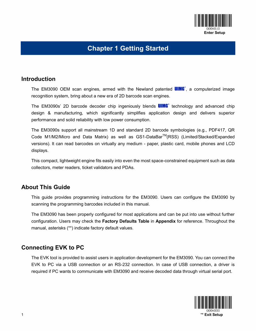
Chapter 1 Getting Started
Introduction The EM3090 OEM scan engines, armed with the Newland patented , a computerized image recognition system, bring about a new era of 2D barcode scan engines.
The EM3090s’ 2D barcode decoder chip ingeniously blends technology and advanced chip design & manufacturing, which significantly simplifies application design and delivers superior performance and solid reliability with low power consumption.
The EM3090s support all mainstream 1D and standard 2D barcode symbologies (e.g., PDF417, QR Code M1/M2/Micro and Data Matrix) as well as GS1-DataBarTM(RSS) (Limited/Stacked/Expanded versions). It can read barcodes on virtually any medium - paper, plastic card, mobile phones and LCD displays.
This compact, lightweight engine fits easily into even the most space-constrained equipment such as data collectors, meter readers, ticket validators and PDAs.
About This Guide This guide provides programming instructions for the EM3090. Users can configure the EM3090 by scanning the programming barcodes included in this manual.
The EM3090 has been properly configured for most applications and can be put into use without further configuration. Users may check the Factory Defaults Table in Appendix for reference. Throughout the manual, asterisks (**) indicate factory default values.
Connecting EVK to PC The EVK tool is provided to assist users in application development for the EM3090. You can connect the EVK to PC via a USB connection or an RS-232 connection. In case of USB connection, a driver is required if PC wants to communicate with EM3090 and receive decoded data through virtual serial port.
Enter Setup
** Exit Setup 2
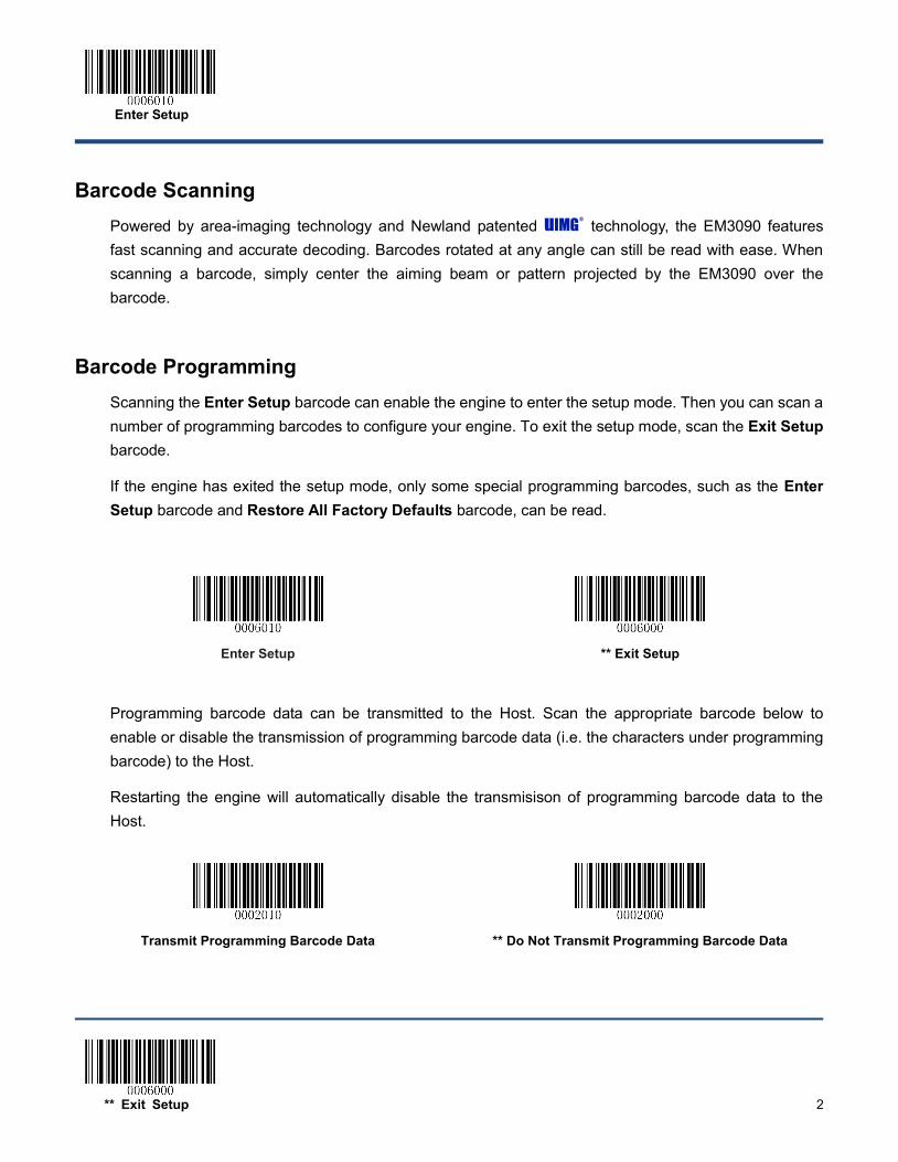
Barcode Scanning Powered by area-imaging technology and Newland patented technology, the EM3090 features fast scanning and accurate decoding. Barcodes rotated at any angle can still be read with ease. When scanning a barcode, simply center the aiming beam or pattern projected by the EM3090 over the barcode.
Barcode Programming Scanning the Enter Setup barcode can enable the engine to enter the setup mode. Then you can scan a number of programming barcodes to configure your engine. To exit the setup mode, scan the Exit Setup barcode.
If the engine has exited the setup mode, only some special programming barcodes, such as the Enter Setup barcode and Restore All Factory Defaults barcode, can be read.
Enter Setup
** Exit Setup
Programming barcode data can be transmitted to the Host. Scan the appropriate barcode below to enable or disable the transmission of programming barcode data (i.e. the characters under programming barcode) to the Host.
Restarting the engine will automatically disable the transmisison of programming barcode data to the Host.
Transmit Programming Barcode Data
** Do Not Transmit Programming Barcode Data
Enter Setup
3 ** Exit Setup
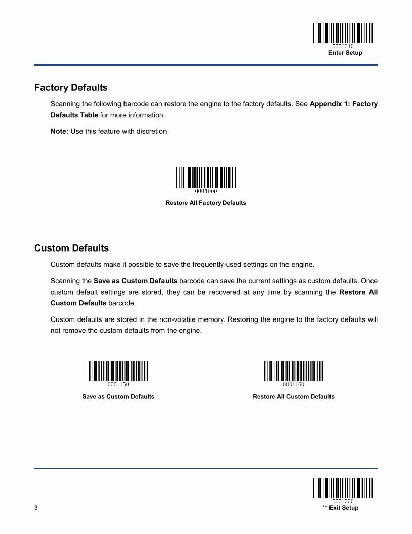
Factory Defaults Scanning the following barcode can restore the engine to the factory defaults. See Appendix 1: Factory Defaults Table for more information.
Note: Use this feature with discretion.
Restore All Factory Defaults
Custom Defaults Custom defaults make it possible to save the frequently-used settings on the engine.
Scanning the Save as Custom Defaults barcode can save the current settings as custom defaults. Once custom default settings are stored, they can be recovered at any time by scanning the Restore All Custom Defaults barcode.
Custom defaults are stored in the non-volatile memory. Restoring the engine to the factory defaults will not remove the custom defaults from the engine.
Save as Custom Defaults
Restore All Custom Defaults
Enter Setup
** Exit Setup 4
Chapter 2 Communication Interfaces
The EM3090 provides a TTL-232 interface and a USB interface (optional) to communicate with the host device. The host device can receive scanned data and send commands to control the engine or to access/alter the configuration information of the engine via the interface.
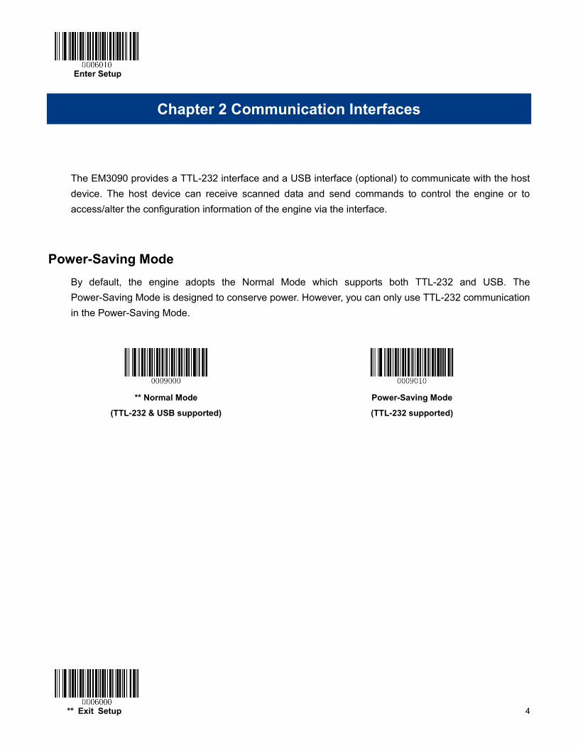
Power-Saving Mode By default, the engine adopts the Normal Mode which supports both TTL-232 and USB. The Power-Saving Mode is designed to conserve power. However, you can only use TTL-232 communication in the Power-Saving Mode.
** Normal Mode
(TTL-232 & USB supported)
Power-Saving Mode
(TTL-232 supported)
Enter Setup
5 ** Exit Setup
TTL-232 Interface Serial communication interface is usually used when connecting the engine to a host device (like PC, POS). However, to ensure smooth communication and accuracy of data, you need to set communication parameters (including baud rate, parity check, data bit and stop bit) to match the host device.
The serial communication interface provided by the engine is based on TTL-level signals. TTL-232 can be used for most application architectures. For those requiring RS-232, an external conversion circuit is needed. The conversion circuit is available only to some models.
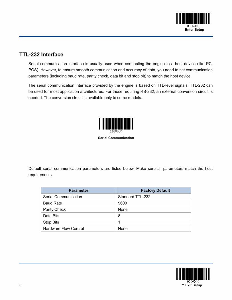
Serial Communication
Default serial communication parameters are listed below. Make sure all parameters match the host requirements.
Parameter Factory Default
Serial Communication Standard TTL-232 Baud Rate 9600 Parity Check None Data Bits 8 Stop Bits 1 Hardware Flow Control None
Enter Setup
** Exit Setup 6
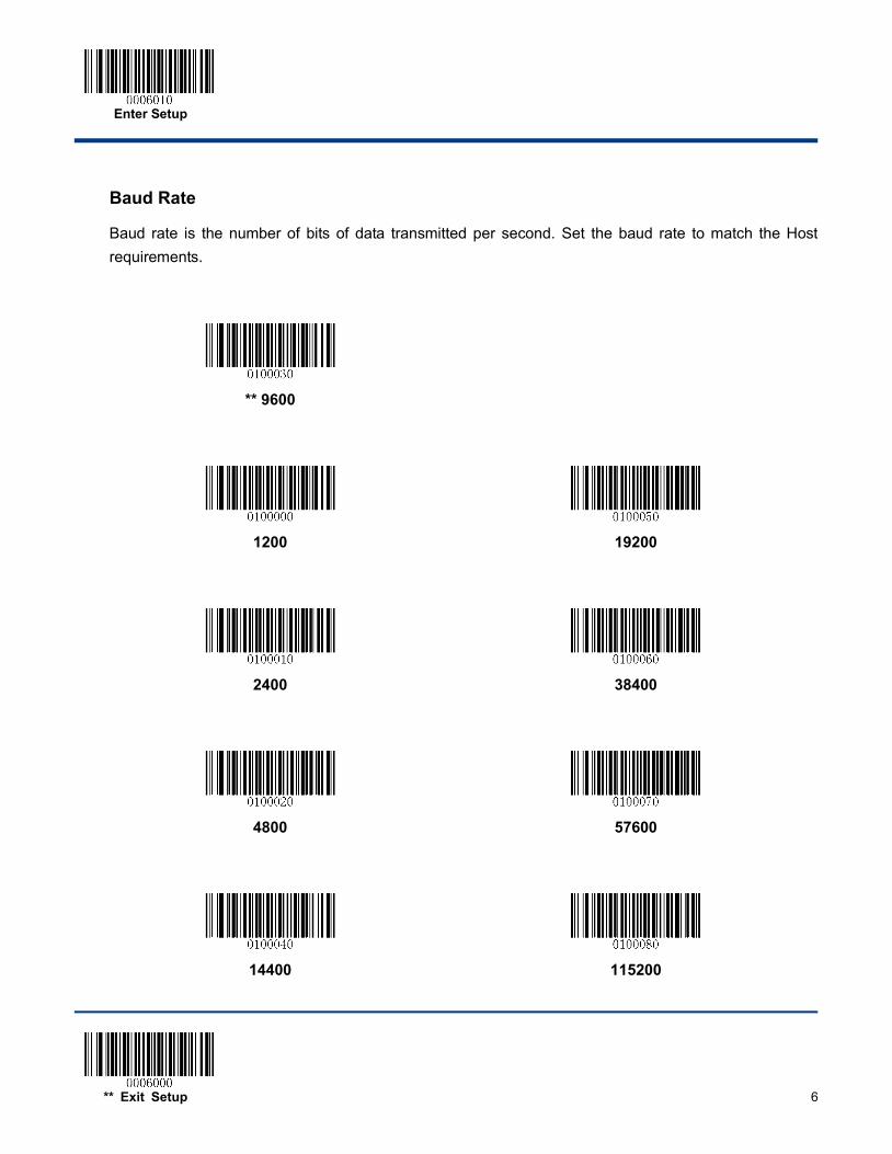
Baud Rate
Baud rate is the number of bits of data transmitted per second. Set the baud rate to match the Host requirements.
** 9600
1200
19200
2400
38400
4800
57600
14400
115200
Enter Setup
7 ** Exit Setup
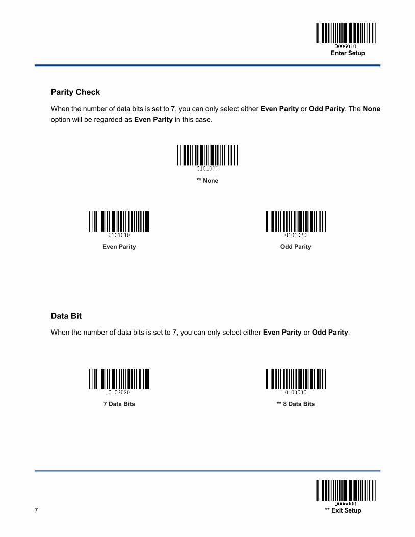
Parity Check
When the number of data bits is set to 7, you can only select either Even Parity or Odd Parity. The None option will be regarded as Even Parity in this case.
** None
Even Parity
Odd Parity
Data Bit
When the number of data bits is set to 7, you can only select either Even Parity or Odd Parity.
7 Data Bits
** 8 Data Bits
Enter Setup
** Exit Setup 8
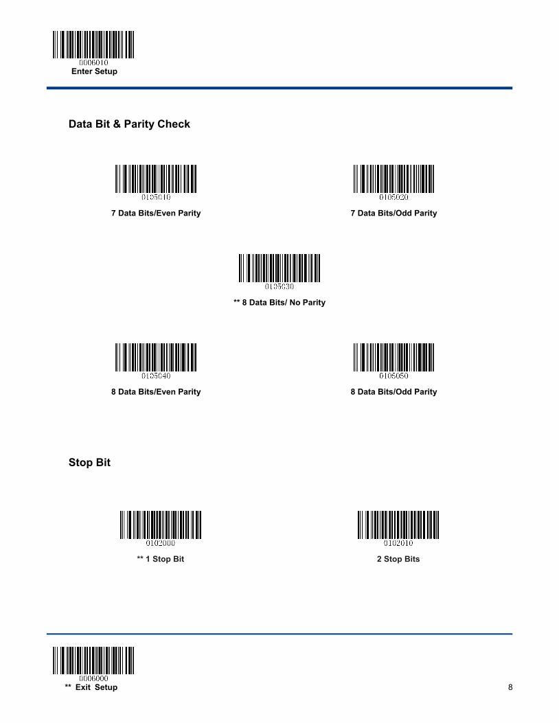
Data Bit & Parity Check
7 Data Bits/Even Parity
7 Data Bits/Odd Parity
** 8 Data Bits/ No Parity
8 Data Bits/Even Parity
8 Data Bits/Odd Parity
Stop Bit
** 1 Stop Bit
2 Stop Bits
Enter Setup
9 ** Exit Setup
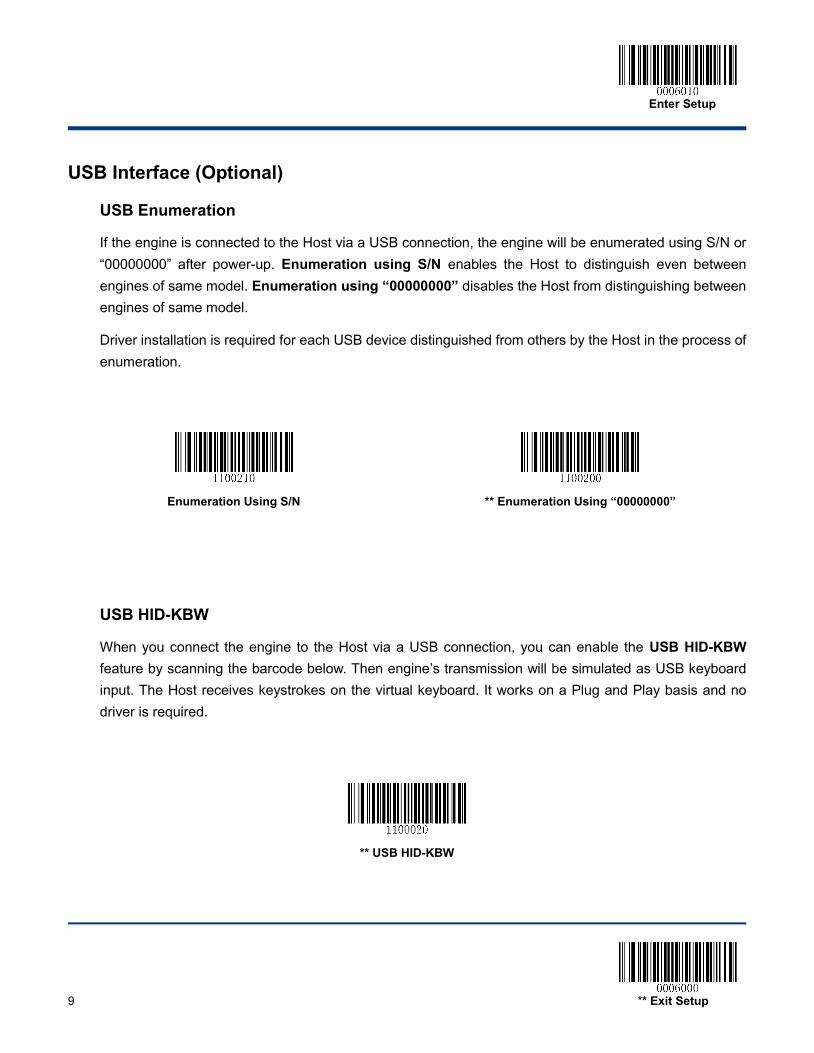
USB Interface (Optional)
USB Enumeration
If the engine is connected to the Host via a USB connection, the engine will be enumerated using S/N or “00000000” after power-up. Enumeration using S/N enables the Host to distinguish even between engines of same model. Enumeration using “00000000” disables the Host from distinguishing between engines of same model.
Driver installation is required for each USB device distinguished from others by the Host in the process of enumeration.
USB HID-KBW
When you connect the engine to the Host via a USB connection, you can enable the USB HID-KBW feature by scanning the barcode below. Then engine’s transmission will be simulated as USB keyboard input. The Host receives keystrokes on the virtual keyboard. It works on a Plug and Play basis and no driver is required.
** USB HID-KBW
Enumeration Using S/N
** Enumeration Using “00000000”
Enter Setup
** Exit Setup 10
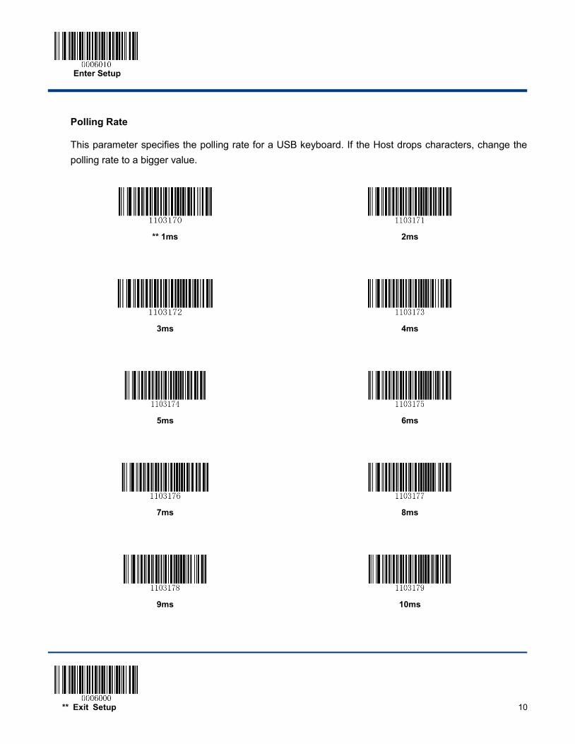
Polling Rate
This parameter specifies the polling rate for a USB keyboard. If the Host drops characters, change the polling rate to a bigger value.
** 1ms
2ms
3ms
4ms
5ms
6ms
7ms
8ms
9ms
10ms
Enter Setup
11 ** Exit Setup
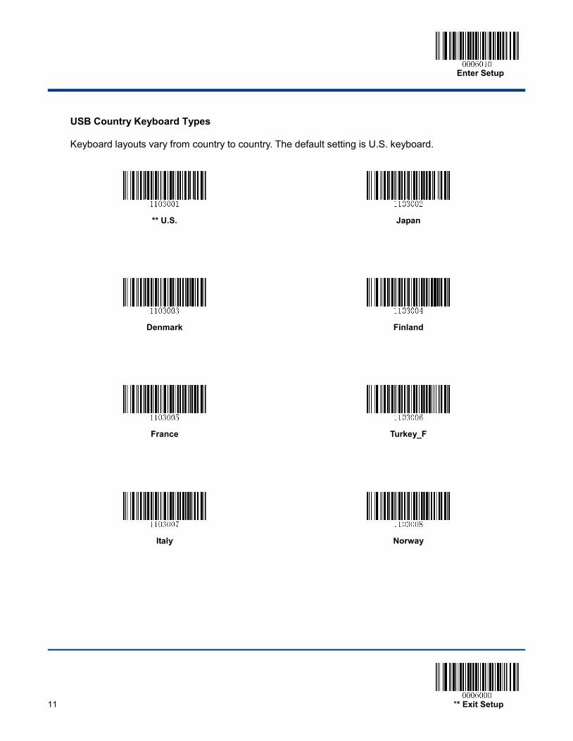
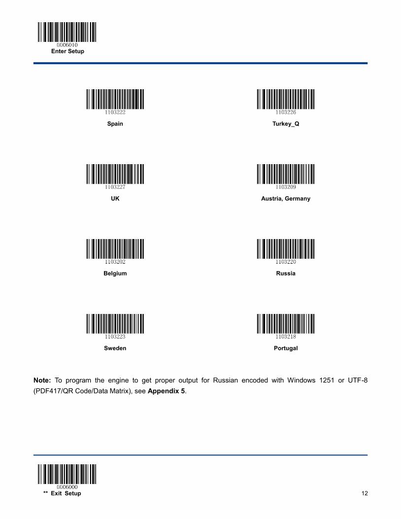
USB Country Keyboard Types
Keyboard layouts vary from country to country. The default setting is U.S. keyboard.
** U.S.
Japan
Denmark
Finland
France
Turkey_F
Italy
Norway
Enter Setup
** Exit Setup 12
Spain
Turkey_Q
UK
Austria, Germany
Belgium
Russia
Sweden
Portugal
Note: To program the engine to get proper output for Russian encoded with Windows 1251 or UTF-8 (PDF417/QR Code/Data Matrix), see Appendix 5.
Enter Setup
13 ** Exit Setup
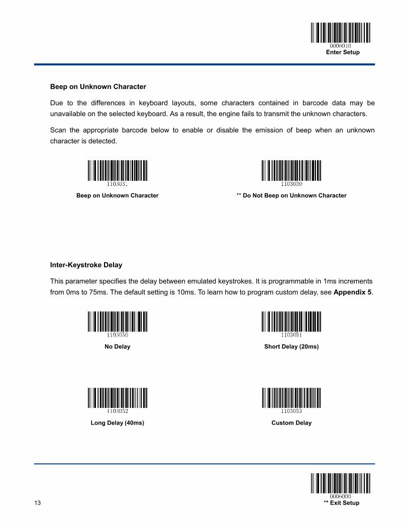
Beep on Unknown Character
Due to the differences in keyboard layouts, some characters contained in barcode data may be unavailable on the selected keyboard. As a result, the engine fails to transmit the unknown characters.
Scan the appropriate barcode below to enable or disable the emission of beep when an unknown character is detected.
Beep on Unknown Character
** Do Not Beep on Unknown Character
Inter-Keystroke Delay
This parameter specifies the delay between emulated keystrokes. It is programmable in 1ms increments from 0ms to 75ms. The default setting is 10ms. To learn how to program custom delay, see Appendix 5.
No Delay
Short Delay (20ms)
Long Delay (40ms)
Custom Delay
Enter Setup
** Exit Setup 14
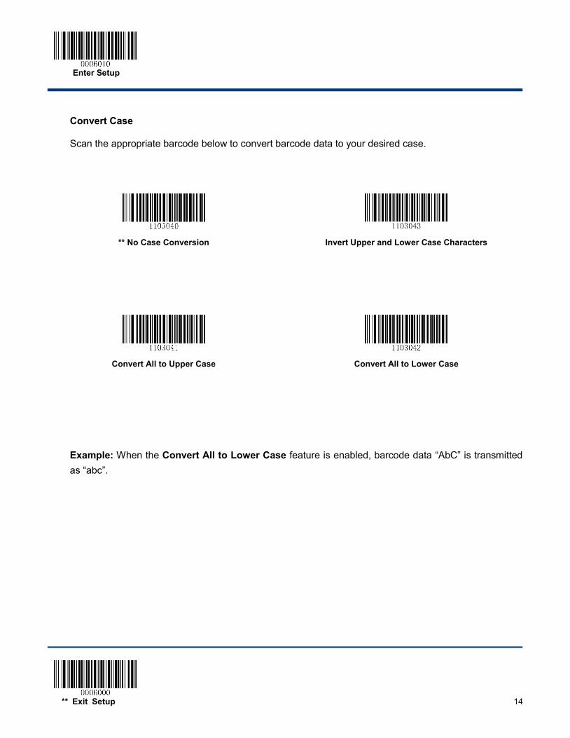
Convert Case
Scan the appropriate barcode below to convert barcode data to your desired case.
** No Case Conversion
Invert Upper and Lower Case Characters
Convert All to Upper Case
Convert All to Lower Case
Example: When the Convert All to Lower Case feature is enabled, barcode data “AbC” is transmitted as “abc”.
Enter Setup
15 ** Exit Setup
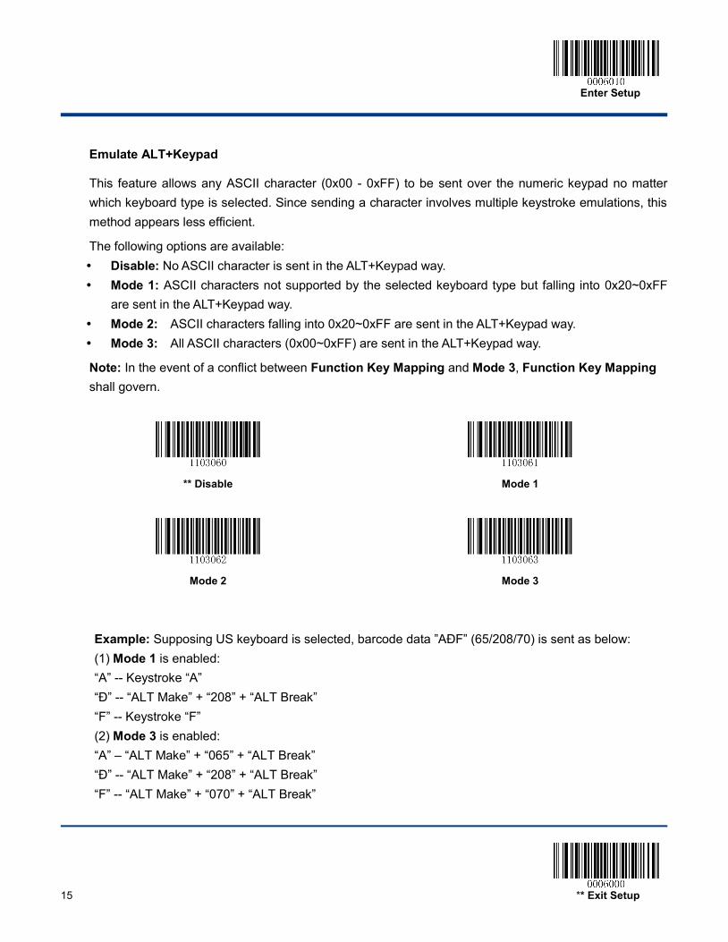
Emulate ALT+Keypad
This feature allows any ASCII character (0x00 - 0xFF) to be sent over the numeric keypad no matter which keyboard type is selected. Since sending a character involves multiple keystroke emulations, this method appears less efficient.
The following options are available: Disable: No ASCII character is sent in the ALT+Keypad way. Mode 1: ASCII characters not supported by the selected keyboard type but falling into 0x20~0xFF
are sent in the ALT+Keypad way. Mode 2: ASCII characters falling into 0x20~0xFF are sent in the ALT+Keypad way. Mode 3: All ASCII characters (0x00~0xFF) are sent in the ALT+Keypad way.
Note: In the event of a conflict between Function Key Mapping and Mode 3, Function Key Mapping shall govern.
** Disable
Mode 1
Mode 2
Mode 3
Example: Supposing US keyboard is selected, barcode data ”AÐF” (65/208/70) is sent as below: (1) Mode 1 is enabled: “A” -- Keystroke “A” “Д -- “ALT Make” + “208” + “ALT Break”
“F” -- Keystroke “F” (2) Mode 3 is enabled: “A” – “ALT Make” + “065” + “ALT Break” “Д -- “ALT Make” + “208” + “ALT Break”
“F” -- “ALT Make” + “070” + “ALT Break”
Enter Setup
** Exit Setup 16
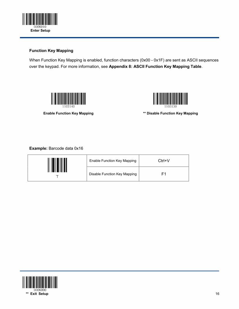
Function Key Mapping
When Function Key Mapping is enabled, function characters (0x00 - 0x1F) are sent as ASCII sequences over the keypad. For more information, see Appendix 8: ASCII Function Key Mapping Table.
Example: Barcode data 0x16
Enable Function Key Mapping Ctrl+V
Disable Function Key Mapping F1
Enable Function Key Mapping
** Disable Function Key Mapping
Enter Setup
17 ** Exit Setup
Emulate Numeric Keypad
When this feature is disabled, sending barcode data is emulated as keystroke(s) on main keyboard.
To enable this feature, scan the Emulate Numeric Keypad barcode. Sending a number (0-9) is emulated as keystroke(s) on numeric keypad, whereas sending other characters like “+”, “_”, “*” , “/” and “.” is still emulated as keystrokes on main keyboard.
** Do Not Emulate Numeric Keypad
Emulate Numeric Keypad
Code Page
In order to support more international characters, the Code Page programming feature is provided. This feature is only effective when ASCII characters are sent in the ALT+Keypad way. Programming a code page requires scanning numeric barcode (For more information, see Appendix 9: Code Pages List). The default code page is Windows 1252 (Latin I). To learn how to program it, see Appendix 5.
Set the Code Page
Enter Setup
** Exit Setup 18
USB COM Port Emulation
If you connect the engine to the Host via a USB connection, the USB COM Port Emulation feature allows the Host to receive data in the way as a serial port does. A driver is required for this feature.
USB COM Port Emulation
USB HID-POS
Introduction
The USB HID-POS interface is recommended for new application programs. It can send up to 56 characters in a single USB report and appears more efficient than keyboard emulation.
Features:
HID based, no custom driver required.
Way more efficient in communication than keyboard emulation and traditional RS-232 interface.
Note: USB HID-POS does not require a custom driver. However, a HID interface on Windows 98 does. All HID interfaces employ standard driver provided by the operating system. Use defaults when installing the driver.
USB HID-POS
Enter Setup
19 ** Exit Setup
Access the Engine with Your Program
Use CreateFile to access the engine as a HID device and then use ReadFile to deliver the scanned data to the application program. Use WriteFile to send data to the engine.
For detailed information about USB and HID interfaces, go to www.USB.org.
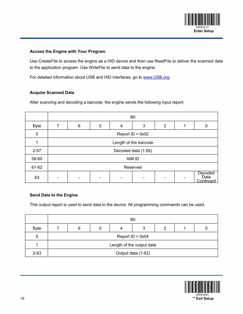
Acquire Scanned Data
After scanning and decoding a barcode, the engine sends the following input report:
Bit
Byte 7 6 5 4 3 2 1 0
0 Report ID = 0x02
1 Length of the barcode
2-57 Decoded data (1-56)
58-60 AIM ID
61-62 Reserved
63 - - - - - - - Decoded
Data Continued
Send Data to the Engine
This output report is used to send data to the device. All programming commands can be used.
Bit
Byte 7 6 5 4 3 2 1 0
0 Report ID = 0x04
1 Length of the output data
2-63 Output data (1-62)
Enter Setup
** Exit Setup 20
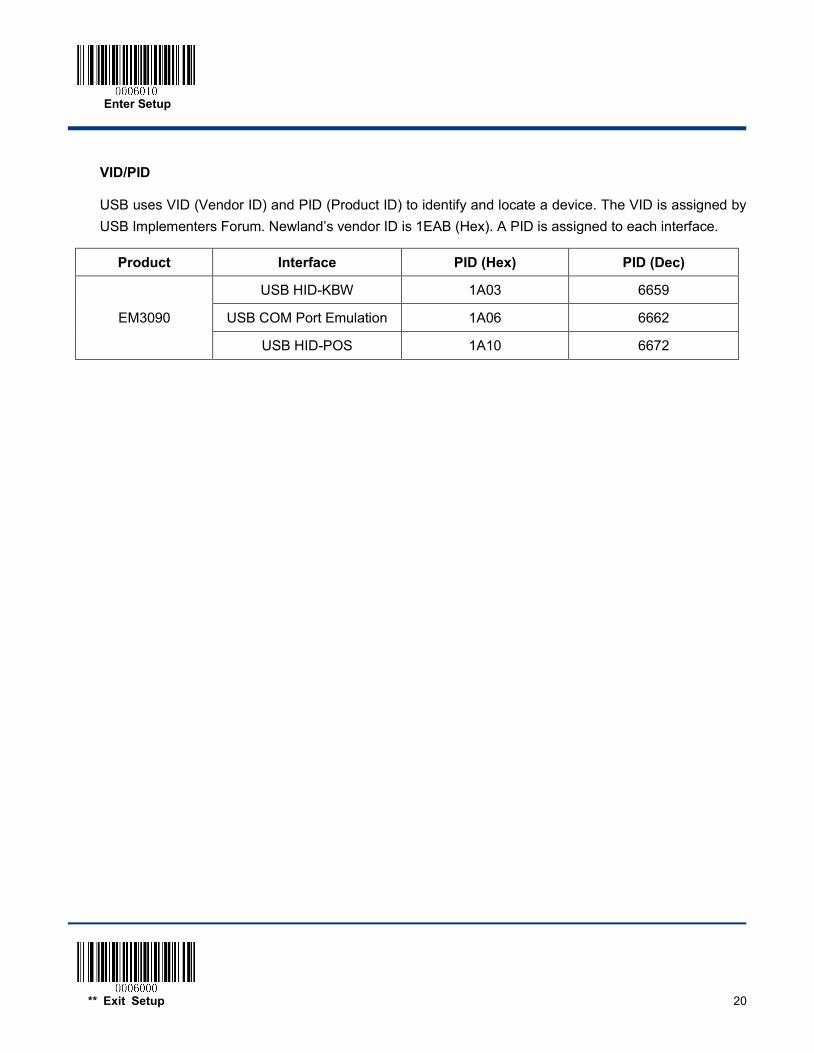
VID/PID
USB uses VID (Vendor ID) and PID (Product ID) to identify and locate a device. The VID is assigned by USB Implementers Forum. Newland’s vendor ID is 1EAB (Hex). A PID is assigned to each interface.
Product Interface PID (Hex) PID (Dec)
EM3090
USB HID-KBW 1A03 6659
USB COM Port Emulation 1A06 6662
USB HID-POS 1A10 6672

Enter Setup
21 ** Exit Setup
Chapter 3 Scan Mode
Batch Mode If the Batch Mode is enabled, driving the TRIG pin on the host interface connector low activates a round of multiple decode sessions. This round of multiple scans continues until the active trigger signal is no longer present. Rereading the same barcode is not allowed if it was decoded previously in the same round. For good read, the engine transmits decoded data via communication port. To activate another round of multiple scans, the Host needs to first negate the trigger, waits 20ms or longer and then drive the TRIG pin low.
Batch Mode
Enter Setup
** Exit Setup 22
Trigger Mode If the Trigger Mode is enabled, driving the TRIG pin on the host interface connector low activates a decode session. The session continues until the barcode is decoded or decode session timeout expires or the active trigger signal is no longer present. For good read, the engine transmits decoded data via communication port. To activate another session, the Host needs to first negate the trigger, waits 20ms or longer and then drive the TRIG pin low.
** Trigger Mode
Decode Session Timeout
This parameter sets the maximum time decode session continues during a scan attempt. It is programmable in 1ms increments from 0ms to 3,600,000ms. The default setting is 3,000ms. To learn how to program this parameter, see Appendix 5.
Decode Session Timeout
Enter Setup
23 ** Exit Setup
Level Trigger/Pulse Trigger
Level trigger: Decode session is activated and continued by constant active trigger signal. The decode session ends once the barcode is decoded or decode session timeout expires.
Pulse trigger: Decode session is activated by electric pulse of trigger signal. The decode session continues until the barcode is decoded or decode session timeout expires.
Auto Sleep
Auto Sleep allows the engine in the Trigger Mode to automatically enter the sleep or low power mode if no operation or communication is performed for a time period (user programmable). When the engine is in the sleep mode, receiving trigger signal or communication from the Host can awake the engine. The engine returns to full operation within 100ms.
The parameter below specifies how long the engine remains idle (no operation or communication occurs) before it is put into sleep mode. It is programmable in 1ms increments from 0ms to 65,535ms. The default setting is 500ms. To learn how to program this parameter, see Appendix 5.
** Level Trigger
Pulse Trigger
** Enable Auto Sleep
Disable Auto Sleep
Time Period from Idle to Sleep
Enter Setup
** Exit Setup 24
Timeout between Decodes (Same Barcode)
Timeout between Decodes (Same Barcode) can avoid undesired rereading of same barcode in a given period of time.
To enable/disable the Timeout between Decodes (Same Barcode), scan the appropriate barcode below.
Enable Timeout between Decodes: Do not allow the engine to re-read same barcode before the timeout between decodes (same barcode) expires.
Disable Timeout between Decodes: Allow the engine to re-read same barcode.
The following parameter sets the timeout between decodes for same barcode. It is programmable in 1ms increments from 0ms to 65,535ms. The default setting is 1,500ms.
To learn how to program this parameter, see Appendix 5.
Timeout between Decodes (Same Barcode)
** Disable Timeout between Decodes
Enable Timeout between Decodes
Enter Setup
25 ** Exit Setup
Sense Mode If the Sense Mode is enabled, the engine activates a decode session every time it detects a change in ambient illumination. The decode session continues until the barcode is decoded or the decode session timeout expires.
Driving the TRIG pin on the host interface connector low can also activate a decode session. The decode session continues until the active trigger signal is no longer present or the barcode is decoded or the decode session timeout expires. The trigger signal needs to be negated before the engine is able to monitor ambient illumination again.
Sense Mode
Decode Session Timeout This parameter sets the maximum time decode session continues during a scan attempt. If the timeout expires or the barcode is decoded, the engine goes back to monitoring ambient illumination. It is programmable in 1ms increments from 0ms to 3,600,000ms. The default setting is 3,000ms. To learn how to program this parameter, see Appendix 5.
Decode Session Timeout
Image Stabilization Timeout The image stabilization timeout is programmable in 1ms increments from 0ms to 1,600ms. The default setting is 500ms.To learn how to program this parameter, see Appendix 5.
Image Stabilization Timeout
Enter Setup
** Exit Setup 26
Continue after Good Read
Continue after Good Read: The engine starts next decode session after a good read.
Pause after Good Read: The engine starts another round of illumination monitoring and image stabilization after a good read.
Timeout between Decodes (Same Barcode)
Timeout between Decodes (Same Barcode) can avoid undesired rereading of same barcode in a given period of time.
To enable/disable the Timeout between Decodes (Same Barcode), scan the appropriate barcode below.
Enable Timeout between Decodes: Do not allow the engine to re-read same barcode before the timeout between decodes (same barcode) expires.
Disable Timeout between Decodes: Allow the engine to re-read same barcode.
** Disable Timeout between Decodes
Enable Timeout between Decodes
** Pause after Good Read
Continue after Good Read
Enter Setup
27 ** Exit Setup
The following parameter sets the timeout between decodes for same barcode. It is programmable in 1ms increments from 0ms to 65,535ms. The default setting is 1,500ms.
To learn how to program this parameter, see Appendix 5.
Sensitivity
Sensitivity specifies the degree of acuteness of the engine’s response to changes in ambient illumination. The higher the sensitivity, the lower requirement in illumination change to trigger the engine. You can select an appropriate degree of sensitivity that fits the ambient environment.
Medium Sensitivity
Low Sensitivity
High Sensitivity
Enhanced Sensitivity
Timeout between Decodes (Same Barcode)

Enter Setup
** Exit Setup 28
If the above four options fail to meet your needs, you may program the threshold value of illumination change.
Illumination changes that reach or surpass the predefined threshold value will cause the engine to start a decode session. The lower the threshold value, the greater the sensitivity of the engine. The default threshold value is 2.
To learn how to program this parameter, see Appendix 5.
Threshold Value of Illumination Change (1-20)
Enter Setup
29 ** Exit Setup
Continuous Mode This mode enables the engine to scan/capture, decode and transmit over and over again.
When the engine is operating in Continuous Mode, barcode reading can be suspended/resumed through control over the trigger signal. When barcode reading is in progress, negating the trigger signal after having maintained it for 30ms or longer will suspend barcode reading; when barcode reading is suspended, performing the same control over the trigger signal will resume barcode reading.
Continuous Mode
Decode Session Timeout
This parameter sets the maximum time decode session continues during a scan attempt. It is programmable in 1ms increments from 0ms to 3,600,000ms. The default setting is 3,000ms. To learn how to program this parameter, see Appendix 5.
Decode Session Timeout
Timeout between Decodes
This parameter sets the timeout between decode sessions. When a decode session ends, next session will not happen until the timeout between decodes expires. It is programmable in 1ms increments from 0ms to 65,535ms. The default setting is 1,000ms. To learn how to program this parameter, see Appendix 5.
Timeout between Decodes
Enter Setup
** Exit Setup 30
Timeout between Decodes (Same Barcode)
Timeout between Decodes (Same Barcode) can avoid undesired rereading of same barcode in a given period of time.
To enable/disable the Timeout between Decodes (Same Barcode), scan the appropriate barcode below.
Enable Timeout between Decodes: Do not allow the engine to re-read same barcode before the timeout between decodes (same barcode) expires.
Disable Timeout between Decodes: Allow the engine to re-read same barcode.
** Disable Timeout between Decodes
Enable Timeout between Decodes
The following parameter sets the timeout between decodes for same barcode. It is programmable in 1ms increments from 0ms to 65,535ms. The default setting is 1,500ms.
To learn how to program this parameter, see Appendix 5.
Timeout between Decodes (Same Barcode)
Enter Setup
31 ** Exit Setup
Chapter 4 Scanning Preferences
Introduction
This chapter contains information as to how to adapt your engine to various applications with preference setting. For instance, to narrow the field of view of the engine to make sure it reads only those barcodes intended by the user.
Decode Area
Whole Area Decoding
When this option is enabled, the engine attempts to decode barcode(s) within its field of view, from the center to the periphery, and transmits the barcode that has been first decoded.
** Whole Area Decoding
Central Area Decoding
The engine attempts to decode barcode(s) within a specified central area and transmits the barcode that has been first decoded. This option allows the engine to narrow its field of view to make sure it reads only those barcodes intended by the user. For instance, if multiple barcodes are placed closely together, central area decoding in conjunction with appropriate pre-defined central area will insure that only the desired barcode is read.
Central Area Decoding
Enter Setup
** Exit Setup 32
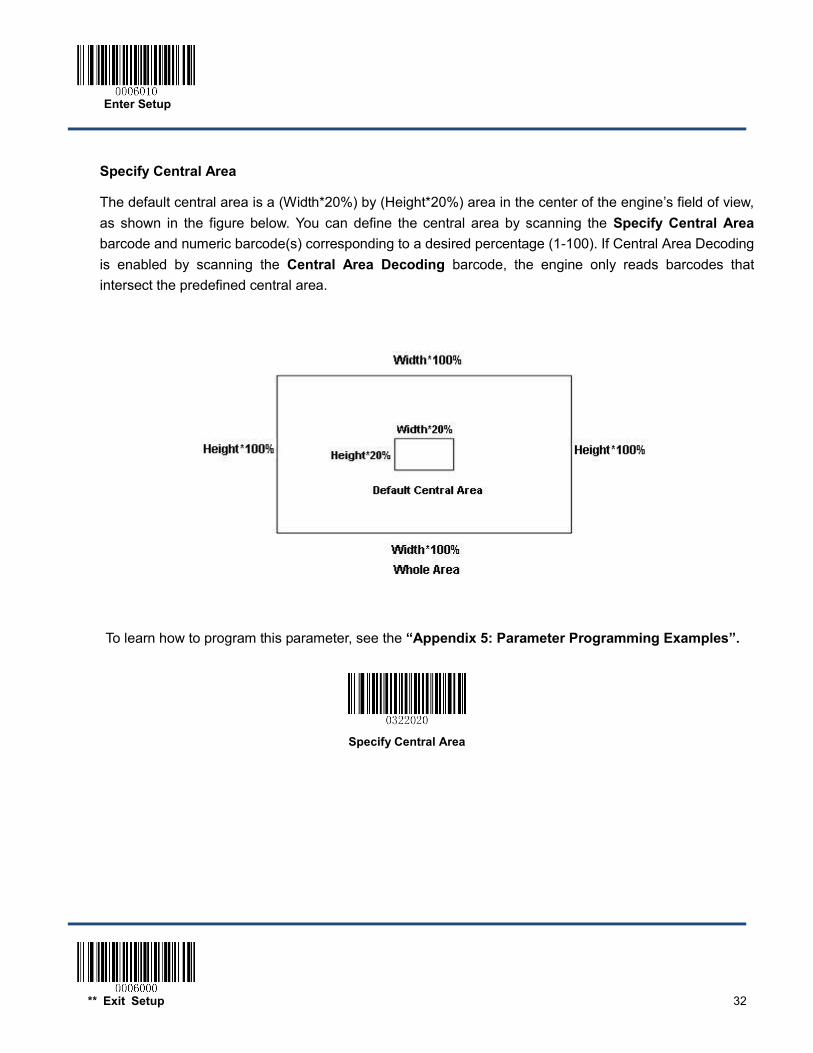
Specify Central Area
The default central area is a (Width*20%) by (Height*20%) area in the center of the engine’s field of view, as shown in the figure below. You can define the central area by scanning the Specify Central Area barcode and numeric barcode(s) corresponding to a desired percentage (1-100). If Central Area Decoding is enabled by scanning the Central Area Decoding barcode, the engine only reads barcodes that intersect the predefined central area.
To learn how to program this parameter, see the “Appendix 5: Parameter Programming Examples”.
Specify Central Area
Enter Setup
33 ** Exit Setup
Chapter 5 Illumination & Aiming
Illumination A couple of illumination options are provided to improve the lighting conditions during every image capture:
Normal: Illumination LEDs are turned on during image capture.
Always ON: Illumination LEDs keep ON after the engine is powered on.
OFF: Illumination LEDs are OFF all the time.
** Normal
OFF
Always ON
Enter Setup
** Exit Setup 34
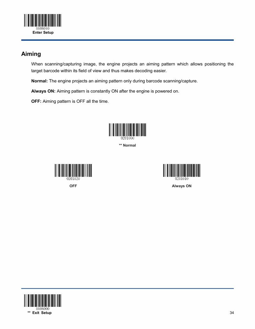
Aiming When scanning/capturing image, the engine projects an aiming pattern which allows positioning the target barcode within its field of view and thus makes decoding easier.
Normal: The engine projects an aiming pattern only during barcode scanning/capture.
Always ON: Aiming pattern is constantly ON after the engine is powered on.
OFF: Aiming pattern is OFF all the time.
** Normal
OFF
Always ON

Enter Setup
35 ** Exit Setup
Chapter 6 Beep & LED Notifications
Startup Beep If startup beep is enabled, the engine will beep after being turned on.
** Enable Startup Beep
Disable Startup Beep
Enter Setup
** Exit Setup 36
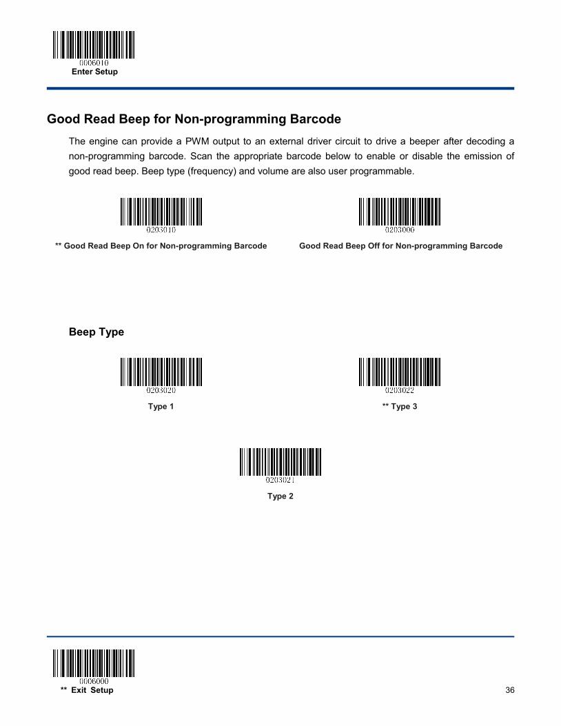
Good Read Beep for Non-programming Barcode The engine can provide a PWM output to an external driver circuit to drive a beeper after decoding a non-programming barcode. Scan the appropriate barcode below to enable or disable the emission of good read beep. Beep type (frequency) and volume are also user programmable.
** Good Read Beep On for Non-programming Barcode
Good Read Beep Off for Non-programming Barcode
Beep Type
Type 1
** Type 3
Type 2
Enter Setup
37 ** Exit Setup
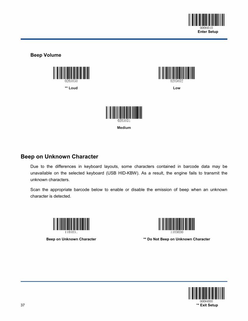
Beep Volume
** Loud
Low
Medium
Beep on Unknown Character Due to the differences in keyboard layouts, some characters contained in barcode data may be unavailable on the selected keyboard (USB HID-KBW). As a result, the engine fails to transmit the unknown characters.
Scan the appropriate barcode below to enable or disable the emission of beep when an unknown character is detected.
Beep on Unknown Character
** Do Not Beep on Unknown Character
Enter Setup
** Exit Setup 38
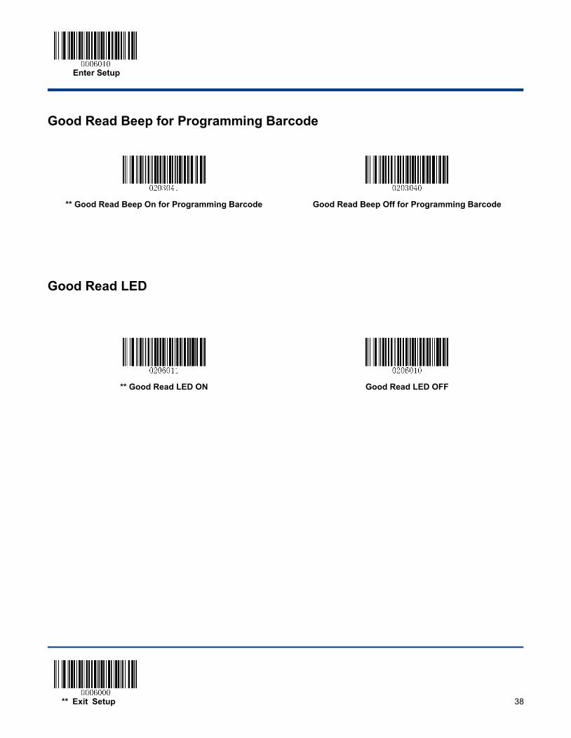
Good Read Beep for Programming Barcode
** Good Read Beep On for Programming Barcode
Good Read Beep Off for Programming Barcode
Good Read LED
** Good Read LED ON
Good Read LED OFF
Enter Setup
39 ** Exit Setup
Transmit NGR Message Scan a barcode below to select whether or not to transmit a user-defined NGR (Not Good Read) message when a barcode is not decoded.
Transmit NGR Message
** Do Not Transmit NGR Message
Edit NGR Message
To edit an NGR message, scan the Edit NGR Message barcode and the numeric barcodes corresponding to the ASCII values (decimal) of desired characters and then scan the Save barcode.
An NGR message can contain 0-7 characters (ASCII value of character: 0-255).
Edit NGR Message
Enter Setup
** Exit Setup 40
Chapter 7 Prefix & Suffix
In many applications, barcode data needs to be edited and distinguished from one another.
Usually AIM ID and Code ID can be used as identifiers, but in some special cases customized prefix and terminating character suffix like Carriage Return or Line Feed can also be the alternatives.
Data formatting may include:
Append AIM ID/Code ID/custom prefix before the decoded data Append custom suffix after the decoded data Append terminating character to the end of the data
The following formats can be used when editing barcode data:
[Code ID] + [Custom Prefix] + [AIM ID] + [DATA] + [Custom Suffix] + [Terminating Character] [Custom Prefix] + [Code ID] + [AIM ID] + [DATA] + [Custom Suffix] + [Terminating Character]
Enter Setup
41 ** Exit Setup
Global Settings
Enable/Disable All Prefix/Suffix
Disable All Prefix/Suffix: Transmit barcode data with no prefix/suffix.
Enable All Prefix/Suffix: Allow user to append Code ID prefix, AIM ID prefix, custom prefix/suffix and terminating character to the barcode data before the transmission.
Enable All Prefix/Suffix
Disable All Prefix/Suffix
Prefix Sequences
Code ID+Custom Prefix+AIM ID
** Custom Prefix+Code ID+AIM ID
Enter Setup
** Exit Setup 42
Custom Prefix
Enable/Disable Custom Prefix
If custom prefix is enabled, you are allowed to append to the data a user-defined prefix that cannot exceed 11 characters.
Enable Custom Prefix
** Disable Custom Prefix
Set Custom Prefix
To set a custom prefix, scan the Set Custom Prefix barcode and the numeric barcodes representing the hexadecimal values of a desired prefix and then scan the Save barcode. Refer to Appendix 4: ASCII Table for hexadecimal values of characters.
Note: A custom prefix cannot exceed 11 characters.
Set Custom Prefix
Example: Set the custom prefix to “CODE” 1. Check the hex values of “CODE” in the ASCII Table. (“CODE”: 43, 4F, 44, 45)
2. Scan the Enter Setup barcode.
3. Scan the Set Custom Prefix barcode.
4. Scan the numeric barcodes “4”, “3”, “4”, “F”, “4”, “4”, “4” and “5”.
5. Scan the Save barcode.
6. Scan the Exit Setup barcode.
Enter Setup
43 ** Exit Setup
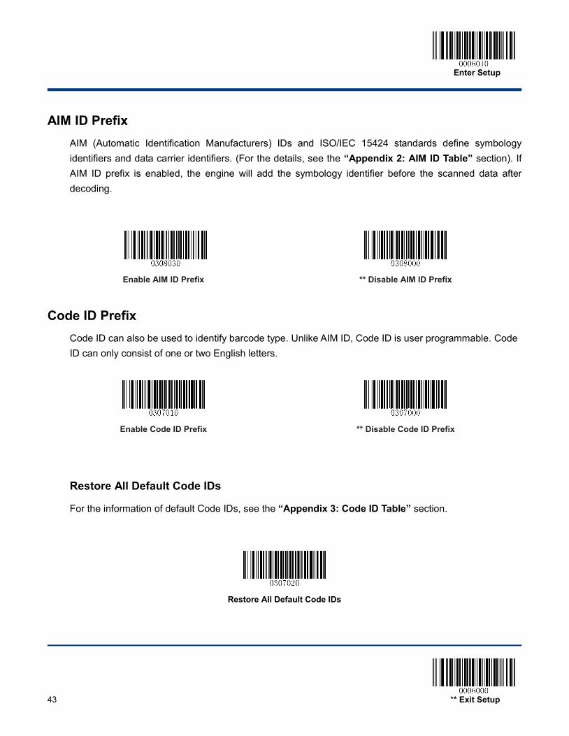
AIM ID Prefix AIM (Automatic Identification Manufacturers) IDs and ISO/IEC 15424 standards define symbology identifiers and data carrier identifiers. (For the details, see the “Appendix 2: AIM ID Table” section). If AIM ID prefix is enabled, the engine will add the symbology identifier before the scanned data after decoding.
Enable AIM ID Prefix
** Disable AIM ID Prefix
Code ID Prefix Code ID can also be used to identify barcode type. Unlike AIM ID, Code ID is user programmable. Code ID can only consist of one or two English letters.
Enable Code ID Prefix
** Disable Code ID Prefix
Restore All Default Code IDs
For the information of default Code IDs, see the “Appendix 3: Code ID Table” section.
Restore All Default Code IDs
Enter Setup
** Exit Setup 44
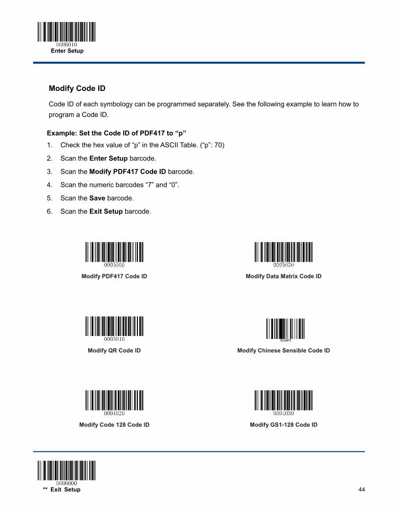
Modify Code ID
Code ID of each symbology can be programmed separately. See the following example to learn how to program a Code ID.
Example: Set the Code ID of PDF417 to “p” 1. Check the hex value of “p” in the ASCII Table. (“p”: 70)
2. Scan the Enter Setup barcode.
3. Scan the Modify PDF417 Code ID barcode.
4. Scan the numeric barcodes “7” and “0”.
5. Scan the Save barcode.
6. Scan the Exit Setup barcode.
Modify PDF417 Code ID
Modify Data Matrix Code ID
Modify QR Code ID
Modify Chinese Sensible Code ID
Modify Code 128 Code ID
Modify GS1-128 Code ID
Enter Setup
45 ** Exit Setup
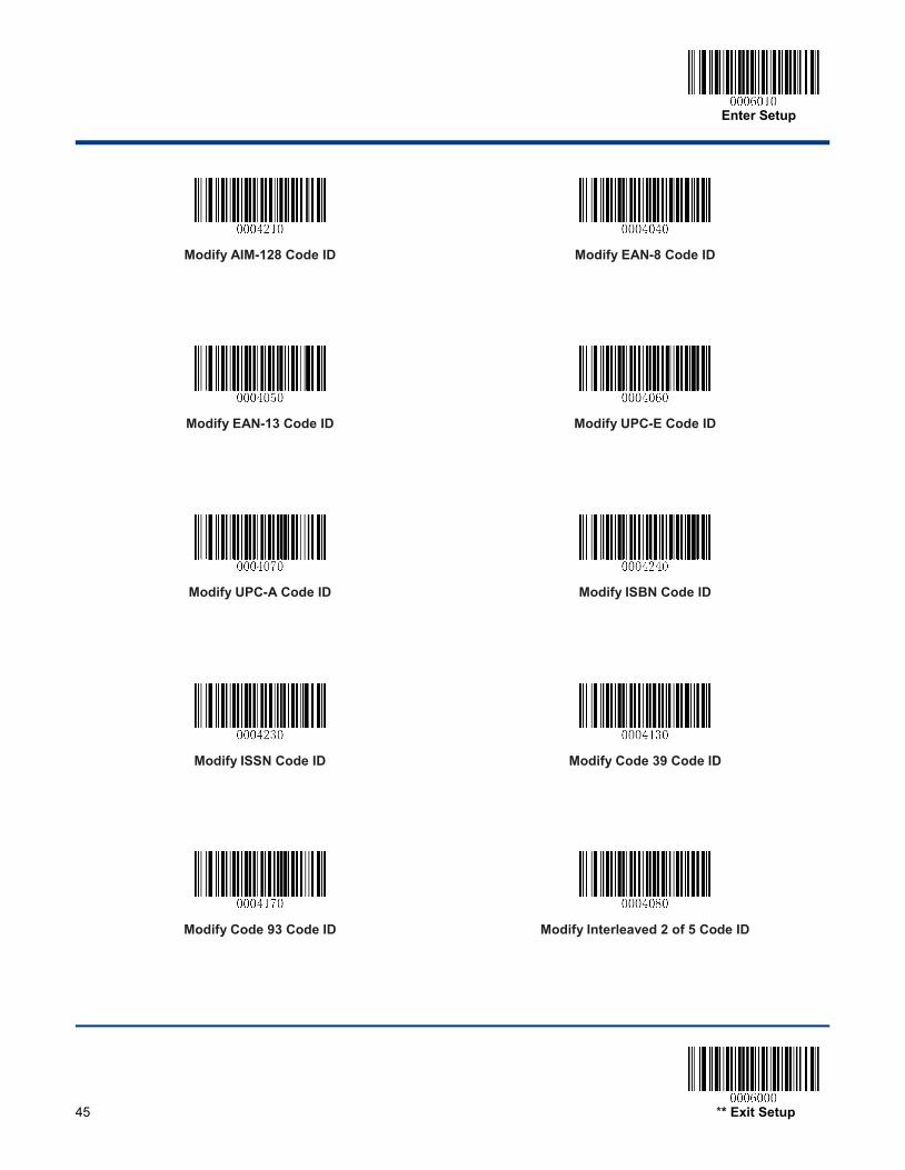
Modify AIM-128 Code ID
Modify EAN-8 Code ID
Modify EAN-13 Code ID
Modify UPC-E Code ID
Modify UPC-A Code ID
Modify ISBN Code ID
Modify ISSN Code ID
Modify Code 39 Code ID
Modify Code 93 Code ID
Modify Interleaved 2 of 5 Code ID
Enter Setup
** Exit Setup 46
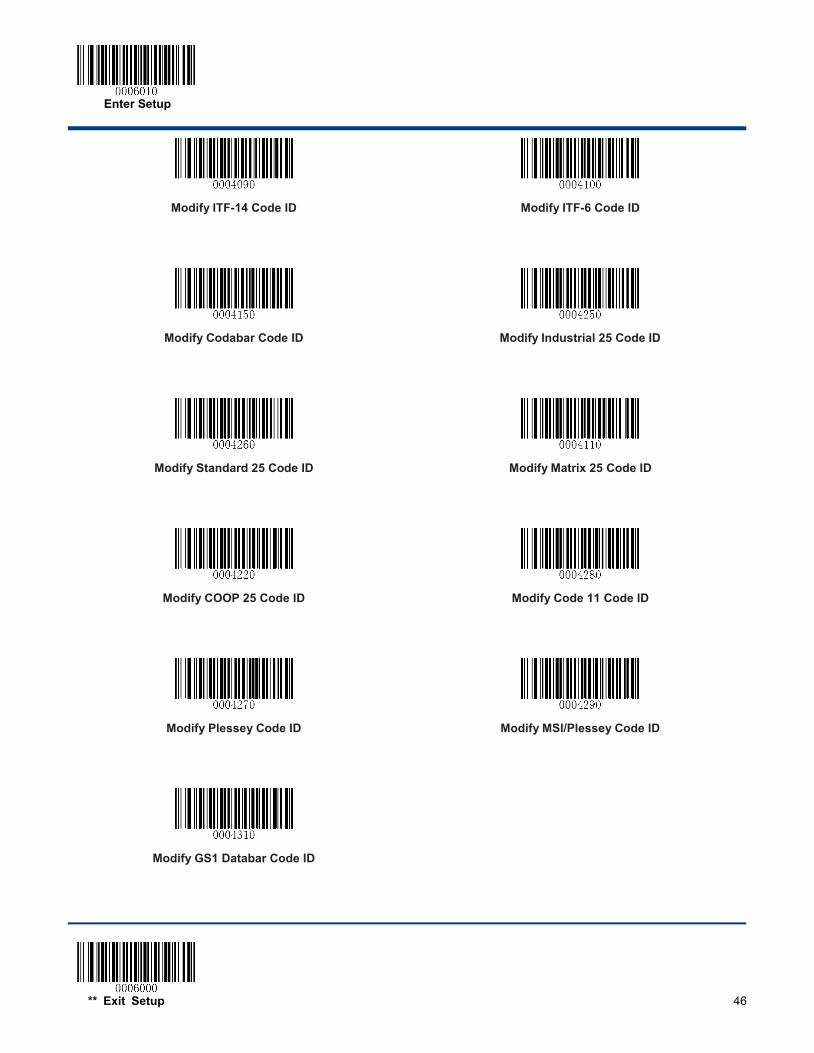
Modify ITF-14 Code ID
Modify ITF-6 Code ID
Modify Codabar Code ID
Modify Industrial 25 Code ID
Modify Standard 25 Code ID
Modify Matrix 25 Code ID
Modify COOP 25 Code ID
Modify Code 11 Code ID
Modify Plessey Code ID
Modify MSI/Plessey Code ID
Modify GS1 Databar Code ID
Enter Setup
47 ** Exit Setup
Custom Suffix
Enable/Disable Custom Suffix
If custom suffix is enabled, you are allowed to append to the data a user-defined suffix that cannot exceed 11 characters.
Enable Custom Suffix
** Disable Custom Suffix
Set Custom Suffix
To set a custom suffix, scan the Set Custom Suffix barcode and the numeric barcodes representing the hexadecimal values of a desired suffix and then scan the Save barcode. Refer to Appendix 4: ASCII Table for hexadecimal values of characters.
Note: A custom suffix cannot exceed 11 characters.
Set Custom Suffix
Example: Set the custom suffix to “CODE” 1. Check the hex values of “CODE” in the ASCII Table. (“CODE”: 43, 4F, 44, 45)
2. Scan the Enter Setup barcode.
3. Scan the Set Custom Suffix barcode.
4. Scan the numeric barcodes “4”, “3”, “4”, “F”, “4”, “4”, “4” and “5”.
5. Scan the Save barcode.
6. Scan the Exit Setup barcode.
Enter Setup
** Exit Setup 48
Terminating Character Suffix A terminating character can be used to mark the end of data, which means nothing can be added after it.
A terminating character suffix can contain 1-7 characters.
Enable/Disable Terminating Character Suffix
To enable/disable terminating character suffix, scan the appropriate barcode below.
** Enable Terminating Character Suffix
Disable Terminating Character Suffix
Enter Setup
49 ** Exit Setup
Set Terminating Character Suffix
The engine provides a shortcut for setting the terminating character suffix to CR (0x0D) or CRLF (0x0D,0x0A) and enabling it by scanning the appropriate barcode below.
** Terminating Character CR (0x0D)
Terminating Character CRLF (0x0D,0x0A)
To set a terminating character suffix, scan the Set Terminating Character Suffix barcode and the numeric barcodes representing the hexadecimal value of a desired terminating character and then scan the Save barcode. Refer to Appendix 4: ASCII Table for hexadecimal values of terminating characters.
Note: A terminating character suffix cannot exceed 7 characters.
Set Terminating Character Suffix
Example: Set the terminating character suffix to 0x0D
1. Scan the Enter Setup barcode.
2. Scan the Set Terminating Character Suffix barcode.
3. Scan the numeric barcodes “0” and “D”.
4. Scan the Save barcode.
5. Scan the Exit Setup barcode.
Enter Setup
** Exit Setup 50
Chapter 8 Symbologies
Global Settings
Enable/Disable All Symbologies
If the Disable All Symbologies feature is enabled, the engine will not be able to read any non-programming barcodes except the programming barcodes.
Enable All Symbologies
Disable All Symbologies
Enable/Disable 1D Symbologies
If the Disable 1D Symbologies feature is enabled, the engine will not be able to read any 1D barcodes.
Enable 1D Symbologies
Disable 1D Symbologies
Enable/Disable 2D Symbologies
If the Disable 2D Symbologies feature is enabled, the engine will not be able to read any 2D barcodes.
Enable 2D Symbologies
Disable 2D Symbologies
Enter Setup
51 ** Exit Setup
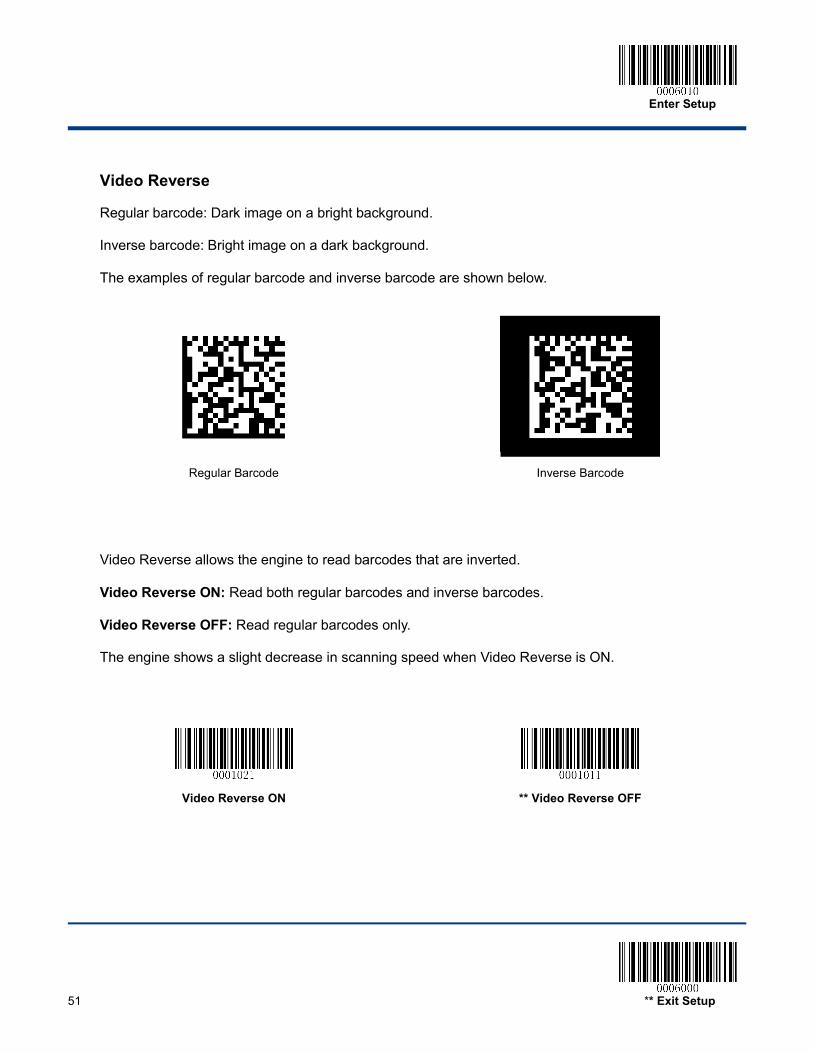
Video Reverse
Regular barcode: Dark image on a bright background.
Inverse barcode: Bright image on a dark background.
The examples of regular barcode and inverse barcode are shown below.
Regular Barcode
Inverse Barcode
Video Reverse allows the engine to read barcodes that are inverted.
Video Reverse ON: Read both regular barcodes and inverse barcodes.
Video Reverse OFF: Read regular barcodes only.
The engine shows a slight decrease in scanning speed when Video Reverse is ON.
Video Reverse ON
** Video Reverse OFF
Enter Setup
** Exit Setup 52
1D Symbologies
Code 128
Restore Factory Defaults
Restore the Factory Defaults of Code 128
Enable/Disable Code 128
** Enable Code 128
Disable Code 128
Set Length Range for Code 128
Set the Minimum Length
Set the Maximum Length
Enter Setup
53 ** Exit Setup
GS1-128 (UCC/EAN-128)
Restore Factory Defaults
Restore the Factory Defaults of GS1-128
Enable/Disable GS1-128
** Enable GS1-128
Disable GS1-128
Set Length Range for GS1-128
Set the Minimum Length
Set the Maximum Length

Enter Setup
** Exit Setup 54
AIM-128
Restore Factory Defaults
Restore the Factory Defaults of AIM-128
Enable/Disable AIM-128
** Enable AIM-128
Disable AIM-128
Set Length Range for AIM-128
Set the Minimum Length
Set the Maximum Length
Enter Setup
55 ** Exit Setup
EAN-8
Restore Factory Defaults
Restore the Factory Defaults of EAN-8
Enable/Disable EAN-8
** Enable EAN-8
Disable EAN-8
Enter Setup
** Exit Setup 56
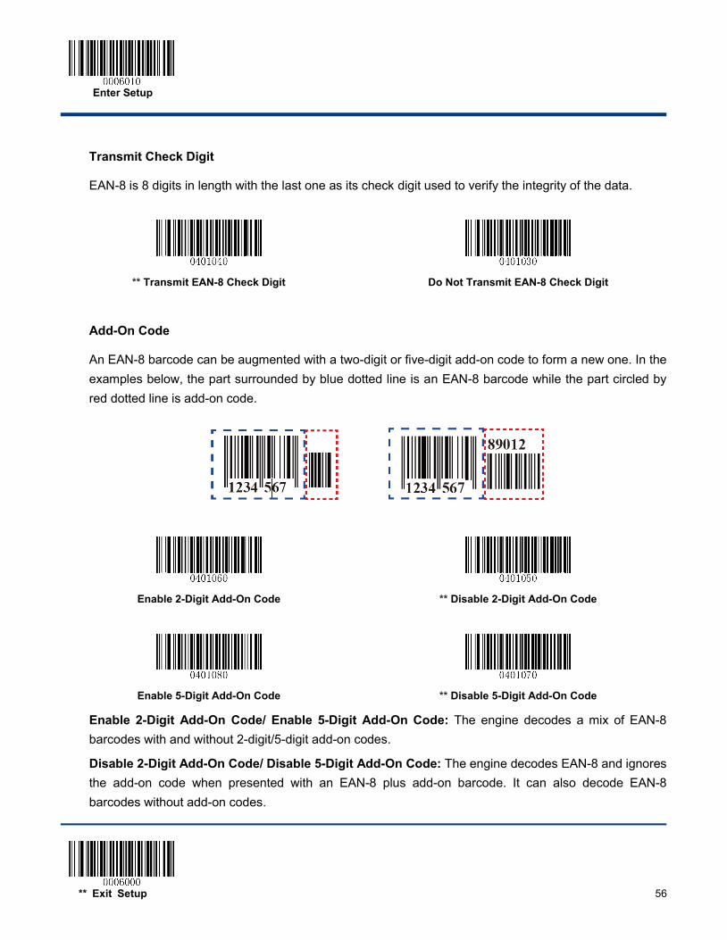
Transmit Check Digit
EAN-8 is 8 digits in length with the last one as its check digit used to verify the integrity of the data.
** Transmit EAN-8 Check Digit
Do Not Transmit EAN-8 Check Digit
Add-On Code
An EAN-8 barcode can be augmented with a two-digit or five-digit add-on code to form a new one. In the examples below, the part surrounded by blue dotted line is an EAN-8 barcode while the part circled by red dotted line is add-on code.
Enable 2-Digit Add-On Code
** Disable 2-Digit Add-On Code
Enable 5-Digit Add-On Code
** Disable 5-Digit Add-On Code
Enable 2-Digit Add-On Code/ Enable 5-Digit Add-On Code: The engine decodes a mix of EAN-8 barcodes with and without 2-digit/5-digit add-on codes.
Disable 2-Digit Add-On Code/ Disable 5-Digit Add-On Code: The engine decodes EAN-8 and ignores the add-on code when presented with an EAN-8 plus add-on barcode. It can also decode EAN-8 barcodes without add-on codes.
Enter Setup
57 ** Exit Setup
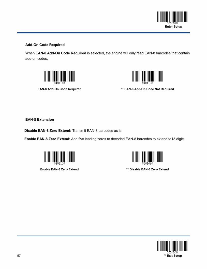
Add-On Code Required
When EAN-8 Add-On Code Required is selected, the engine will only read EAN-8 barcodes that contain add-on codes.
EAN-8 Add-On Code Required
** EAN-8 Add-On Code Not Required
EAN-8 Extension
Disable EAN-8 Zero Extend: Transmit EAN-8 barcodes as is.
Enable EAN-8 Zero Extend: Add five leading zeros to decoded EAN-8 barcodes to extend to13 digits.
Enable EAN-8 Zero Extend
** Disable EAN-8 Zero Extend
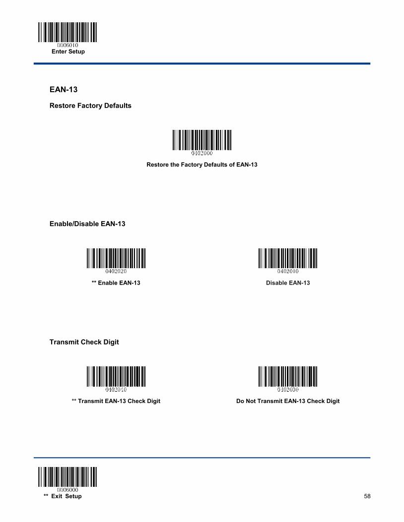
Enter Setup
** Exit Setup 58
EAN-13
Restore Factory Defaults
Restore the Factory Defaults of EAN-13
Enable/Disable EAN-13
** Enable EAN-13
Disable EAN-13
Transmit Check Digit
** Transmit EAN-13 Check Digit
Do Not Transmit EAN-13 Check Digit
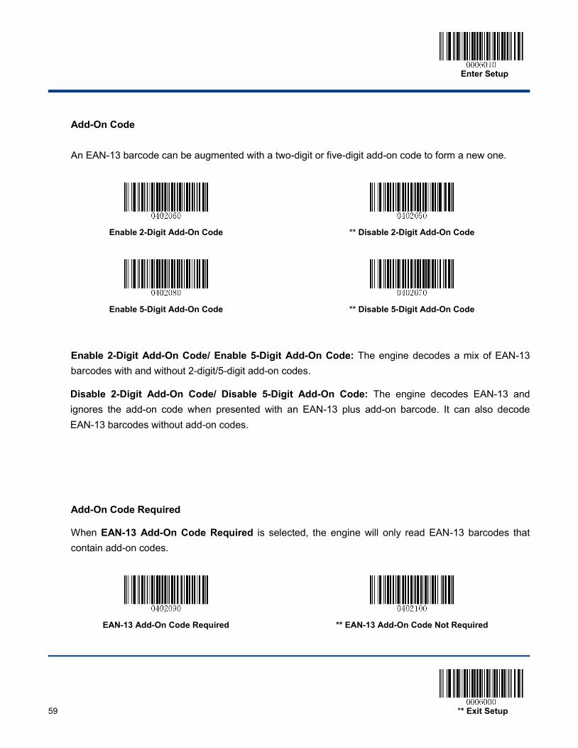
Enter Setup
59 ** Exit Setup
Add-On Code
An EAN-13 barcode can be augmented with a two-digit or five-digit add-on code to form a new one.
Enable 2-Digit Add-On Code
** Disable 2-Digit Add-On Code
Enable 5-Digit Add-On Code
** Disable 5-Digit Add-On Code
Enable 2-Digit Add-On Code/ Enable 5-Digit Add-On Code: The engine decodes a mix of EAN-13 barcodes with and without 2-digit/5-digit add-on codes.
Disable 2-Digit Add-On Code/ Disable 5-Digit Add-On Code: The engine decodes EAN-13 and ignores the add-on code when presented with an EAN-13 plus add-on barcode. It can also decode EAN-13 barcodes without add-on codes.
Add-On Code Required
When EAN-13 Add-On Code Required is selected, the engine will only read EAN-13 barcodes that contain add-on codes.
EAN-13 Add-On Code Required
** EAN-13 Add-On Code Not Required
Enter Setup
** Exit Setup 60
ISSN
Restore Factory Defaults
Restore the Factory Defaults of ISSN
Enable/Disable ISSN
Enable ISSN
** Disable ISSN
Enter Setup
61 ** Exit Setup
Add-On Code
An ISSN barcode can be augmented with a two-digit or five-digit add-on code to form a new one.
Enable 2-Digit Add-On Code
** Disable 2-Digit Add-On Code
Enable 5-Digit Add-On Code
** Disable 5-Digit Add-On Code Enable 2-Digit Add-On Code/ Enable 5-Digit Add-On Code: The engine decodes a mix of ISSN barcodes with and without 2-digit/5-digit add-on codes.
Disable 2-Digit Add-On Code/ Disable 5-Digit Add-On Code: The engine decodes ISSN and ignores the add-on code when presented with an ISSN plus add-on barcode. It can also decode ISSN barcodes without add-on codes.
Add-On Code Required
When ISSN Add-On Code Required is selected, the engine will only read ISSN barcodes that contain add-on codes.
ISSN Add-On Code Required
** ISSN Add-On Code Not Required
Enter Setup
** Exit Setup 62
ISBN
Restore Factory Default
Restore the Factory Defaults of ISBN
Enable/Disable ISBN
** Enable ISBN
Disable ISBN
Set ISBN Format
**ISBN-13
ISBN-10

Enter Setup
63 ** Exit Setup
Add-On Code
An ISBN barcode can be augmented with a two-digit or five-digit add-on code to form a new one.
Enable 2-Digit Add-On Code
** Disable 2-Digit Add-On Code
Enable 5-Digit Add-On Code
** Disable 5-Digit Add-On Code
Enable 2-Digit Add-On Code/ Enable 5-Digit Add-On Code: The engine decodes a mix of ISBN barcodes with and without 2-digit/5-digit add-on codes.
Disable 2-Digit Add-On Code/ Disable 5-Digit Add-On Code: The engine decodes ISBN and ignores the add-on code when presented with an ISBN plus add-on barcode. It can also decode ISBN barcodes without add-on codes.
Add-On Code Required
When ISBN Add-On Code Required is selected, the engine will only read ISBN barcodes that contain add-on codes.
ISBN Add-On Code Required
** ISBN Add-On Code Not Required
Enter Setup
** Exit Setup 64
UPC-E
Restore Factory Defaults
Restore the Factory Defaults of UPC-E
Enable/Disable UPC-E
** Enable UPC-E
Disable UPC-E
Transmit Check Digit
** Transmit UPC-E Check Digit
Do Not Transmit UPC-E Check Digit
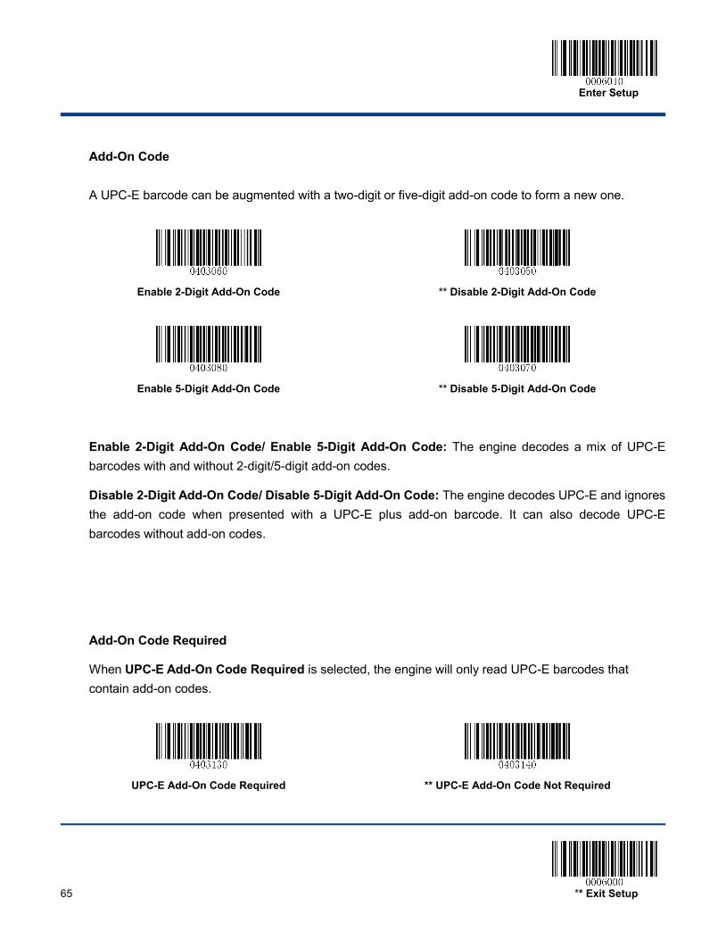
Enter Setup
65 ** Exit Setup
Add-On Code
A UPC-E barcode can be augmented with a two-digit or five-digit add-on code to form a new one.
Enable 2-Digit Add-On Code
** Disable 2-Digit Add-On Code
Enable 5-Digit Add-On Code
** Disable 5-Digit Add-On Code
Enable 2-Digit Add-On Code/ Enable 5-Digit Add-On Code: The engine decodes a mix of UPC-E barcodes with and without 2-digit/5-digit add-on codes.
Disable 2-Digit Add-On Code/ Disable 5-Digit Add-On Code: The engine decodes UPC-E and ignores the add-on code when presented with a UPC-E plus add-on barcode. It can also decode UPC-E barcodes without add-on codes.
Add-On Code Required
When UPC-E Add-On Code Required is selected, the engine will only read UPC-E barcodes that contain add-on codes.
UPC-E Add-On Code Required
** UPC-E Add-On Code Not Required
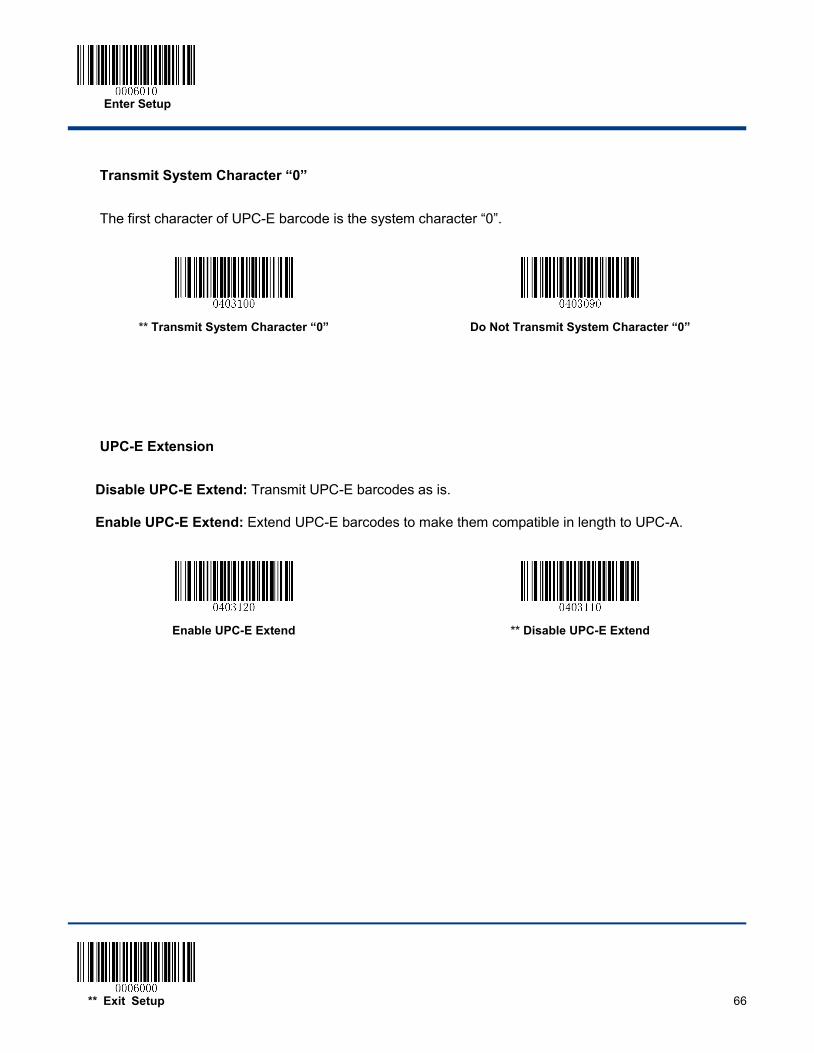
Enter Setup
** Exit Setup 66
Transmit System Character “0”
The first character of UPC-E barcode is the system character “0”.
** Transmit System Character “0”
Do Not Transmit System Character “0”
UPC-E Extension
Disable UPC-E Extend: Transmit UPC-E barcodes as is.
Enable UPC-E Extend: Extend UPC-E barcodes to make them compatible in length to UPC-A.
Enable UPC-E Extend
** Disable UPC-E Extend
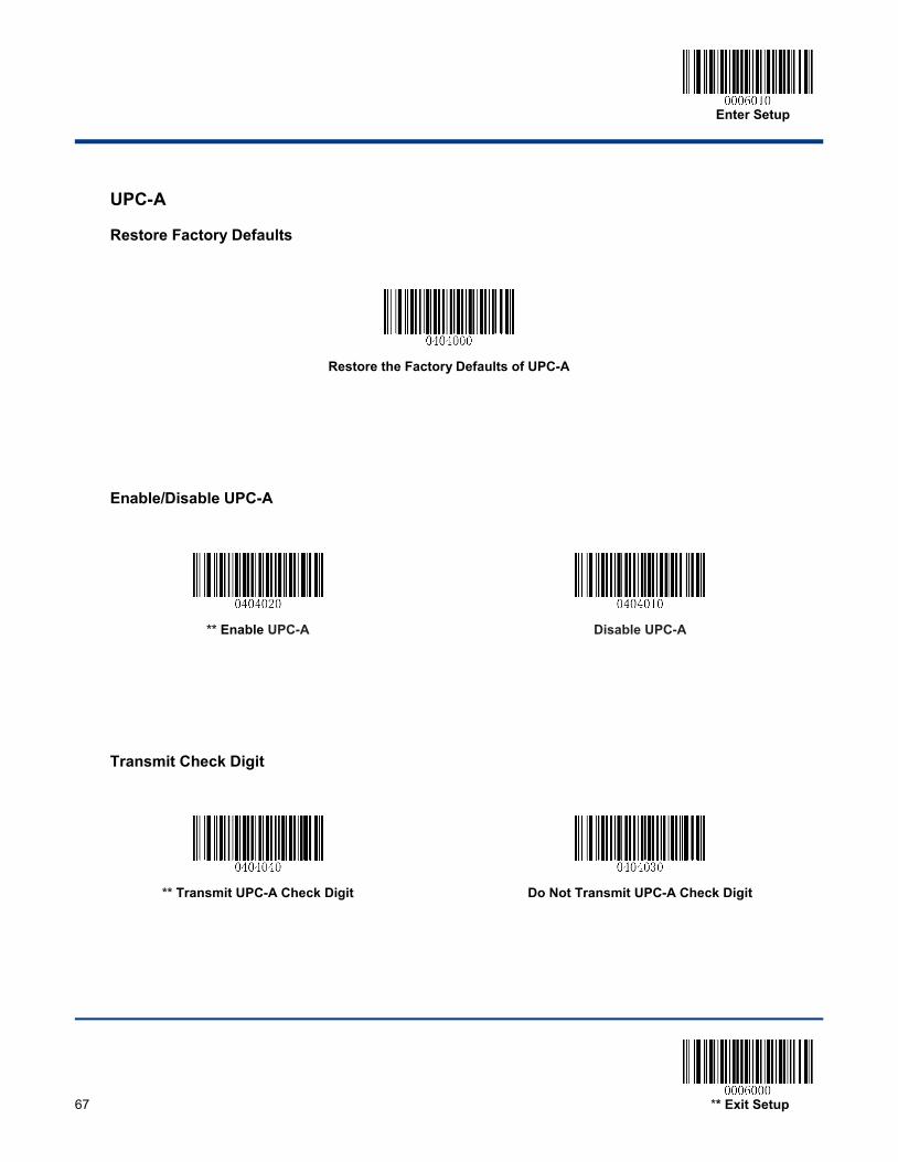
Enter Setup
67 ** Exit Setup
UPC-A
Restore Factory Defaults
Restore the Factory Defaults of UPC-A
Enable/Disable UPC-A
** Enable UPC-A
Disable UPC-A
Transmit Check Digit
** Transmit UPC-A Check Digit
Do Not Transmit UPC-A Check Digit
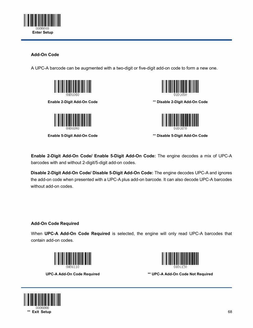
Enter Setup
** Exit Setup 68
Add-On Code
A UPC-A barcode can be augmented with a two-digit or five-digit add-on code to form a new one.
Enable 2-Digit Add-On Code
** Disable 2-Digit Add-On Code
Enable 5-Digit Add-On Code
** Disable 5-Digit Add-On Code
Enable 2-Digit Add-On Code/ Enable 5-Digit Add-On Code: The engine decodes a mix of UPC-A barcodes with and without 2-digit/5-digit add-on codes.
Disable 2-Digit Add-On Code/ Disable 5-Digit Add-On Code: The engine decodes UPC-A and ignores the add-on code when presented with a UPC-A plus add-on barcode. It can also decode UPC-A barcodes without add-on codes.
Add-On Code Required
When UPC-A Add-On Code Required is selected, the engine will only read UPC-A barcodes that contain add-on codes.
UPC-A Add-On Code Required
** UPC-A Add-On Code Not Required
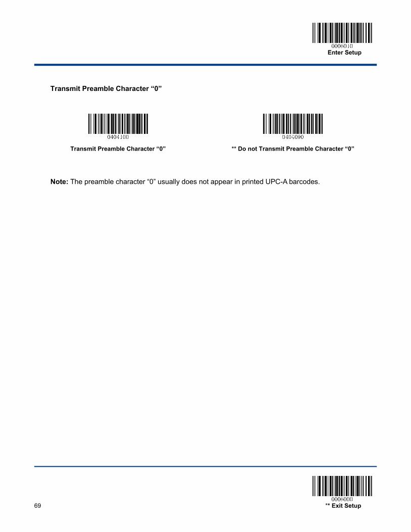
Enter Setup
69 ** Exit Setup
Transmit Preamble Character “0”
Transmit Preamble Character “0”
** Do not Transmit Preamble Character “0”
Note: The preamble character “0” usually does not appear in printed UPC-A barcodes.
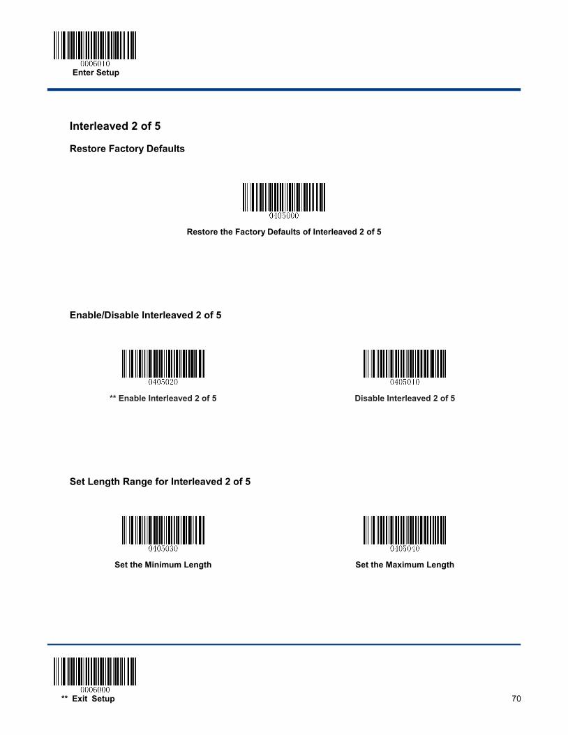
Enter Setup
** Exit Setup 70
Interleaved 2 of 5
Restore Factory Defaults
Restore the Factory Defaults of Interleaved 2 of 5
Enable/Disable Interleaved 2 of 5
** Enable Interleaved 2 of 5
Disable Interleaved 2 of 5
Set Length Range for Interleaved 2 of 5
Set the Minimum Length
Set the Maximum Length
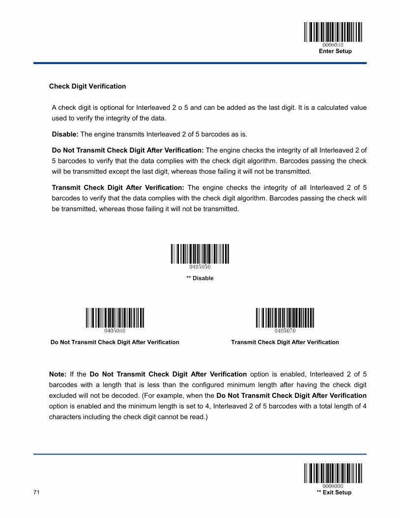
Enter Setup
71 ** Exit Setup
Check Digit Verification
A check digit is optional for Interleaved 2 o 5 and can be added as the last digit. It is a calculated value used to verify the integrity of the data.
Disable: The engine transmits Interleaved 2 of 5 barcodes as is.
Do Not Transmit Check Digit After Verification: The engine checks the integrity of all Interleaved 2 of 5 barcodes to verify that the data complies with the check digit algorithm. Barcodes passing the check will be transmitted except the last digit, whereas those failing it will not be transmitted.
Transmit Check Digit After Verification: The engine checks the integrity of all Interleaved 2 of 5 barcodes to verify that the data complies with the check digit algorithm. Barcodes passing the check will be transmitted, whereas those failing it will not be transmitted.
** Disable
Do Not Transmit Check Digit After Verification
Transmit Check Digit After Verification
Note: If the Do Not Transmit Check Digit After Verification option is enabled, Interleaved 2 of 5 barcodes with a length that is less than the configured minimum length after having the check digit excluded will not be decoded. (For example, when the Do Not Transmit Check Digit After Verification option is enabled and the minimum length is set to 4, Interleaved 2 of 5 barcodes with a total length of 4 characters including the check digit cannot be read.)
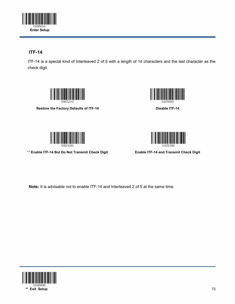
Enter Setup
** Exit Setup 72
ITF-14
ITF-14 is a special kind of Interleaved 2 of 5 with a length of 14 characters and the last character as the check digit.
Restore the Factory Defaults of ITF-14
Disable ITF-14
** Enable ITF-14 But Do Not Transmit Check Digit
Enable ITF-14 and Transmit Check Digit
Note: It is advisable not to enable ITF-14 and Interleaved 2 of 5 at the same time.
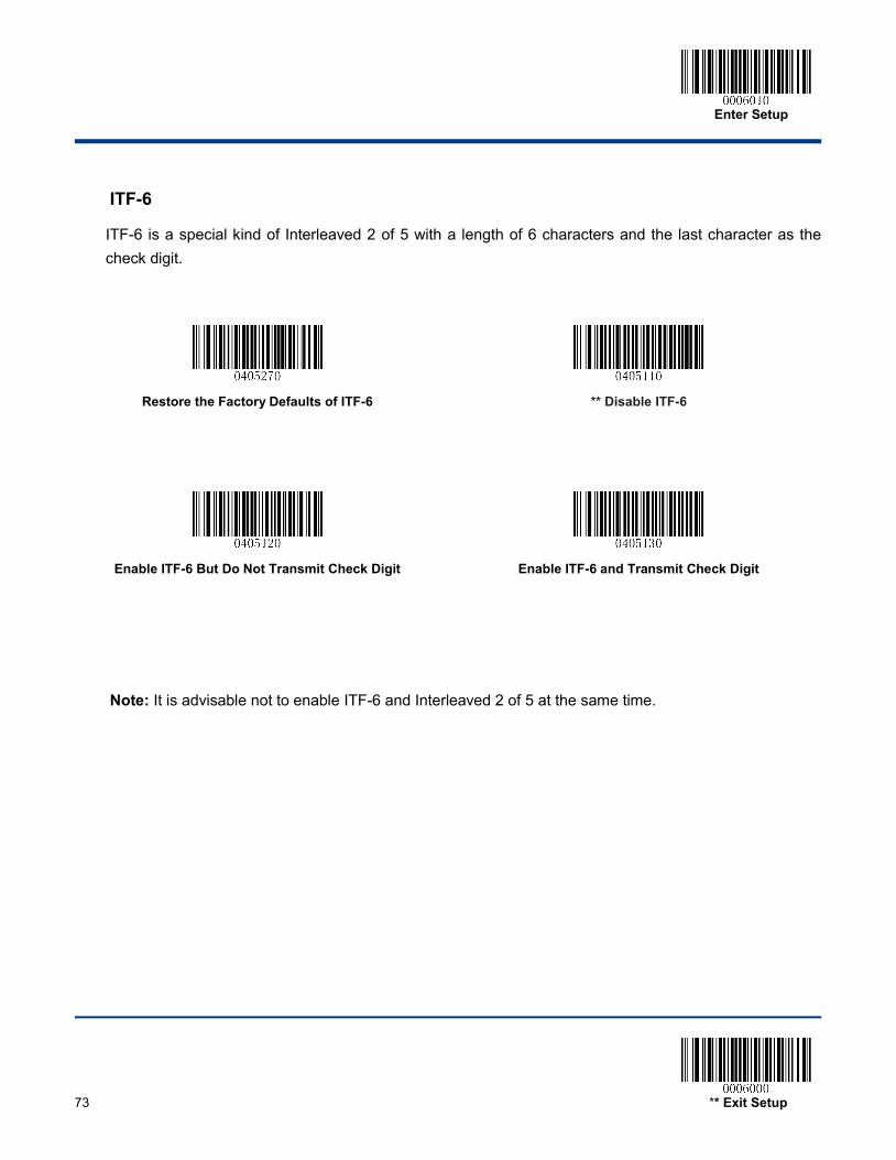
Enter Setup
73 ** Exit Setup
ITF-6
ITF-6 is a special kind of Interleaved 2 of 5 with a length of 6 characters and the last character as the check digit.
Restore the Factory Defaults of ITF-6
** Disable ITF-6
Enable ITF-6 But Do Not Transmit Check Digit
Enable ITF-6 and Transmit Check Digit
Note: It is advisable not to enable ITF-6 and Interleaved 2 of 5 at the same time.

Enter Setup
** Exit Setup 74
Matrix 2 of 5
Restore Factory Defaults
Restore the Factory Defaults of Matrix 2 of 5
Enable/Disable Matrix 2 of 5
Enable Matrix 2 of 5
** Disable Matrix 2 of 5
Set Length Range for Matrix 2 of 5
Set the Minimum Length
Set the Maximum Length
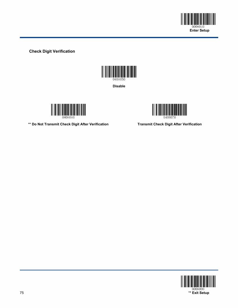
Enter Setup
75 ** Exit Setup
Check Digit Verification
Disable
** Do Not Transmit Check Digit After Verification
Transmit Check Digit After Verification

Enter Setup
** Exit Setup 76
Industrial 2 of 5
Restore Factory Defaults
Restore the Factory Defaults of Industrial 2 of 5
Enable/Disable Industrial 2 of 5
** Enable Industrial 2 of 5
Disable Industrial 2 of 5
Set Length Range for Industrial 2 of 5
Set the Minimum Length
Set the Maximum Length
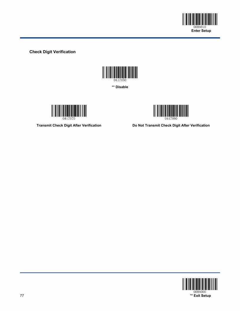
Enter Setup
77 ** Exit Setup
Check Digit Verification
** Disable
Transmit Check Digit After Verification
Do Not Transmit Check Digit After Verification
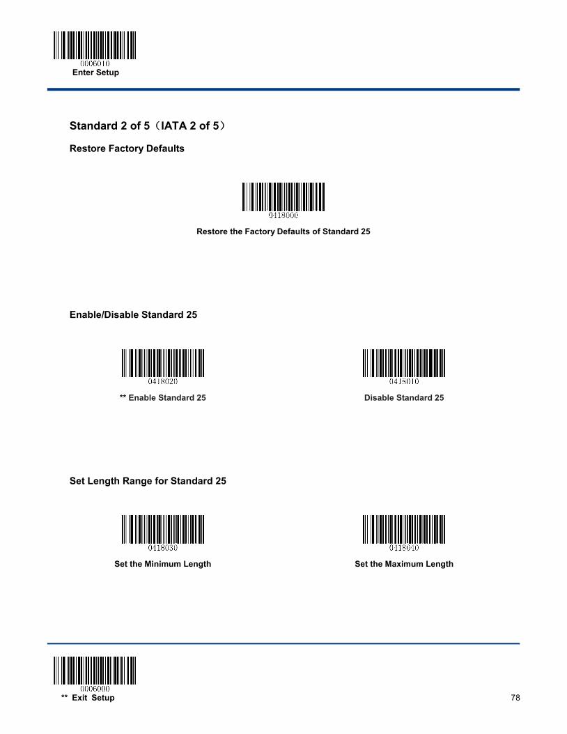
Enter Setup
** Exit Setup 78
Standard 2 of 5(IATA 2 of 5)
Restore Factory Defaults
Restore the Factory Defaults of Standard 25
Enable/Disable Standard 25
** Enable Standard 25
Disable Standard 25
Set Length Range for Standard 25
Set the Minimum Length
Set the Maximum Length

Enter Setup
79 ** Exit Setup
Check Digit Verification
** Disable
Transmit Check Digit After Verification
Do Not Transmit Check Digit After Verification
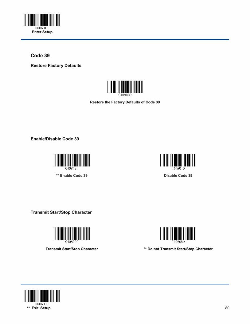
Enter Setup
** Exit Setup 80
Code 39
Restore Factory Defaults
Restore the Factory Defaults of Code 39
Enable/Disable Code 39
** Enable Code 39
Disable Code 39
Transmit Start/Stop Character
Transmit Start/Stop Character
** Do not Transmit Start/Stop Character
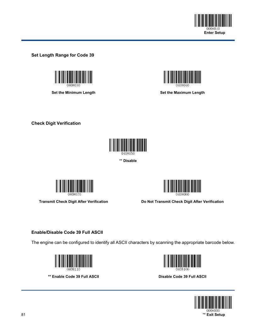
Enter Setup
81 ** Exit Setup
Set Length Range for Code 39
Set the Minimum Length
Set the Maximum Length
Check Digit Verification
** Disable
Transmit Check Digit After Verification
Do Not Transmit Check Digit After Verification
Enable/Disable Code 39 Full ASCII
The engine can be configured to identify all ASCII characters by scanning the appropriate barcode below.
** Enable Code 39 Full ASCII
Disable Code 39 Full ASCII

Enter Setup
** Exit Setup 82
Codabar
Restore Factory Defaults
Restore the Factory Defaults of Codabar
Enable/Disable Codabar
** Enable Codabar
Disable Codabar
Set Length Range for Codabar
Set the Minimum Length
Set the Maximum Length
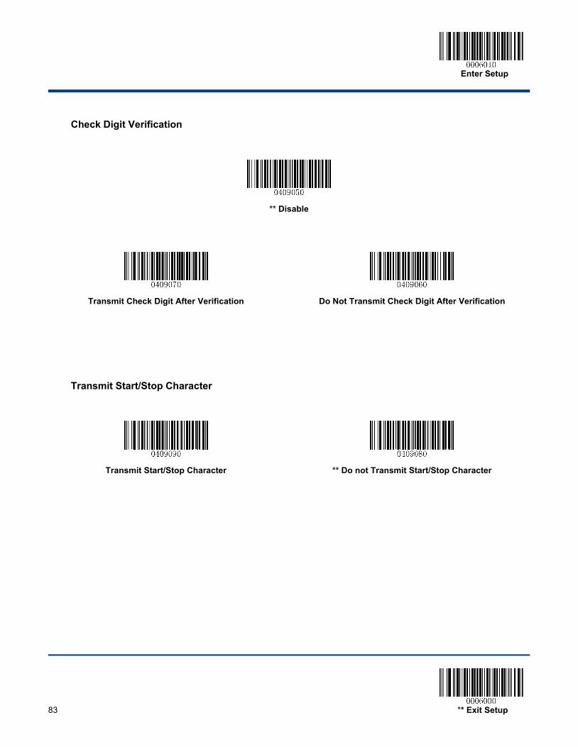
Enter Setup
83 ** Exit Setup
Check Digit Verification
** Disable
Transmit Check Digit After Verification
Do Not Transmit Check Digit After Verification
Transmit Start/Stop Character
Transmit Start/Stop Character
** Do not Transmit Start/Stop Character
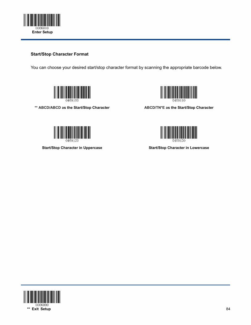
Enter Setup
** Exit Setup 84
Start/Stop Character Format
You can choose your desired start/stop character format by scanning the appropriate barcode below.
** ABCD/ABCD as the Start/Stop Character
ABCD/TN*E as the Start/Stop Character
Start/Stop Character in Uppercase
Start/Stop Character in Lowercase
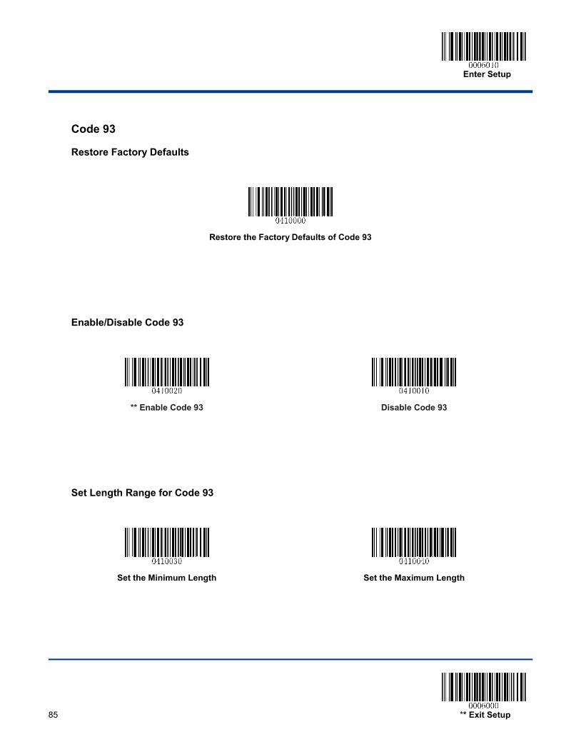
Enter Setup
85 ** Exit Setup
Code 93
Restore Factory Defaults
Restore the Factory Defaults of Code 93
Enable/Disable Code 93
** Enable Code 93
Disable Code 93
Set Length Range for Code 93
Set the Minimum Length
Set the Maximum Length
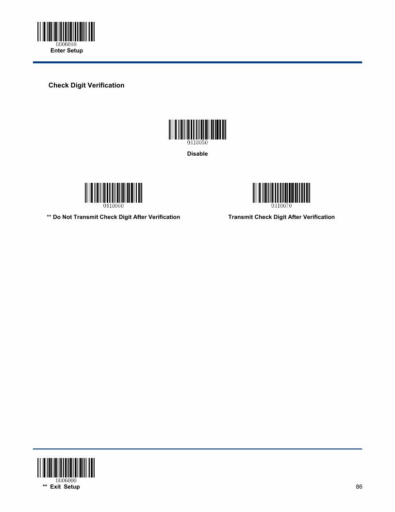
Enter Setup
** Exit Setup 86
Check Digit Verification
Disable
** Do Not Transmit Check Digit After Verification
Transmit Check Digit After Verification
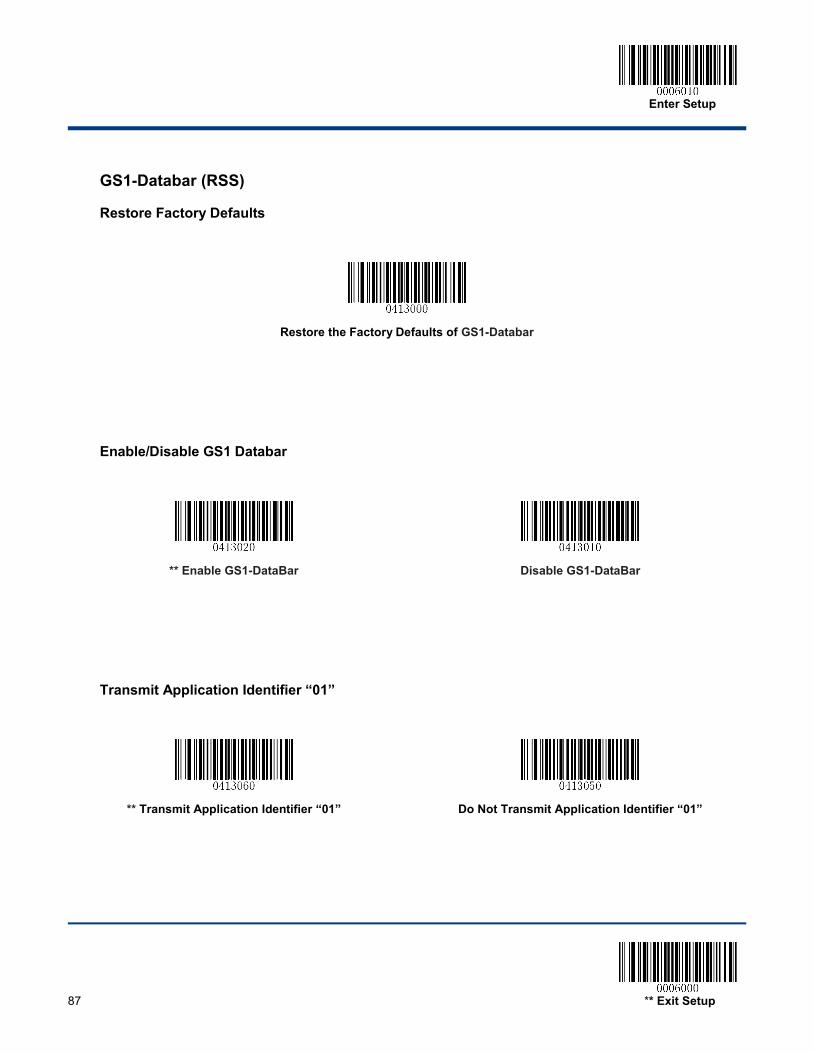
Enter Setup
87 ** Exit Setup
GS1-Databar (RSS)
Restore Factory Defaults
Restore the Factory Defaults of GS1-Databar
Enable/Disable GS1 Databar
** Enable GS1-DataBar
Disable GS1-DataBar
Transmit Application Identifier “01”
** Transmit Application Identifier “01”
Do Not Transmit Application Identifier “01”
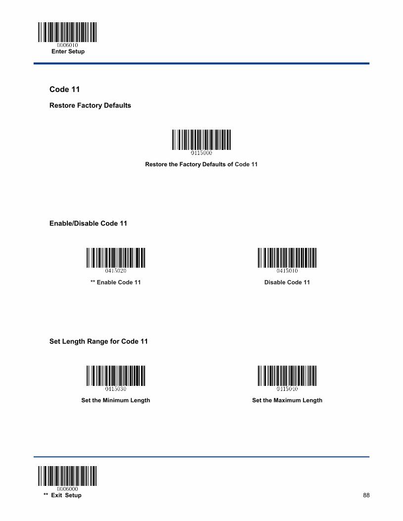
Enter Setup
** Exit Setup 88
Code 11
Restore Factory Defaults
Restore the Factory Defaults of Code 11
Enable/Disable Code 11
** Enable Code 11
Disable Code 11
Set Length Range for Code 11
Set the Minimum Length
Set the Maximum Length
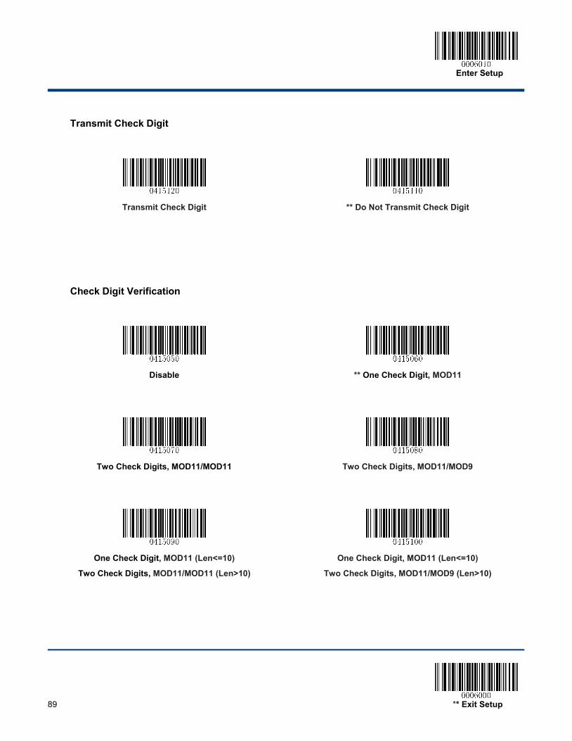
Enter Setup
89 ** Exit Setup
Transmit Check Digit
Transmit Check Digit
** Do Not Transmit Check Digit
Check Digit Verification
Disable
** One Check Digit, MOD11
Two Check Digits, MOD11/MOD11
Two Check Digits, MOD11/MOD9
One Check Digit, MOD11 (Len<=10)
Two Check Digits, MOD11/MOD11 (Len>10)
One Check Digit, MOD11 (Len<=10)
Two Check Digits, MOD11/MOD9 (Len>10)
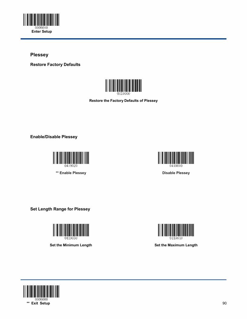
Enter Setup
** Exit Setup 90
Plessey
Restore Factory Defaults
Restore the Factory Defaults of Plessey
Enable/Disable Plessey
** Enable Plessey
Disable Plessey
Set Length Range for Plessey
Set the Minimum Length
Set the Maximum Length
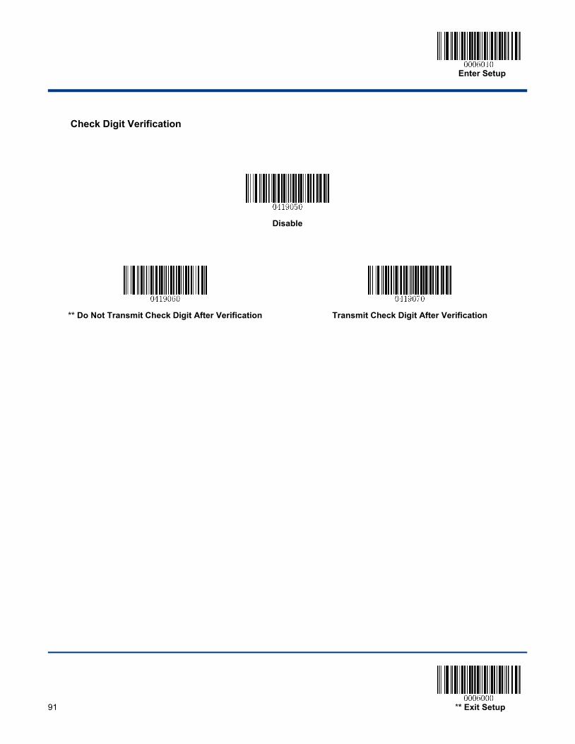
Enter Setup
91 ** Exit Setup
Check Digit Verification
Disable
** Do Not Transmit Check Digit After Verification
Transmit Check Digit After Verification

Enter Setup
** Exit Setup 92
MSI-Plessey
Restore Factory Defaults
Restore the Factory Defaults of MSI-Plessey
Enable/Disable MSI-Plessey
** Enable MSI-Plessey
Disable MSI-Plessey
Set Length Range for MSI-Plessey
Set the Minimum Length
Set the Maximum Length
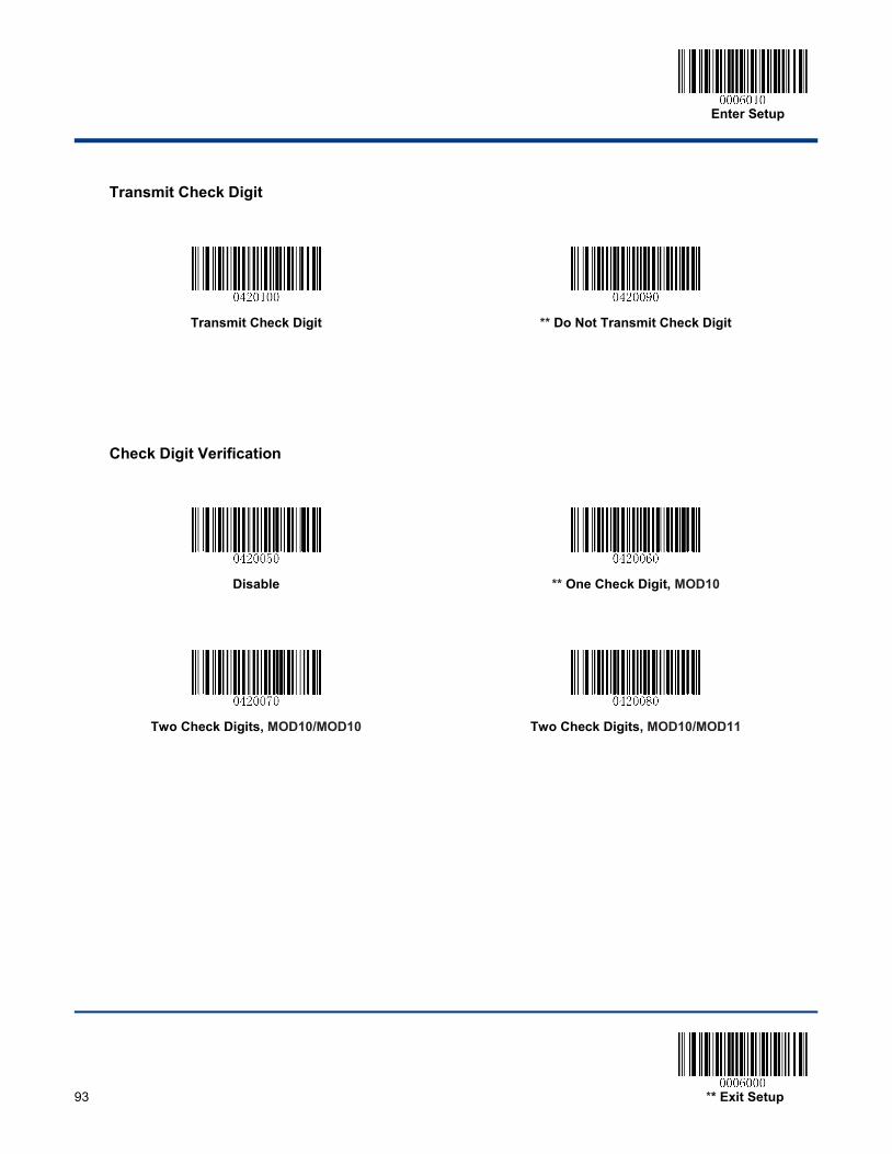
Enter Setup
93 ** Exit Setup
Transmit Check Digit
Transmit Check Digit
** Do Not Transmit Check Digit
Check Digit Verification
Disable
** One Check Digit, MOD10
Two Check Digits, MOD10/MOD10
Two Check Digits, MOD10/MOD11
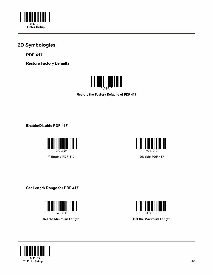
Enter Setup
** Exit Setup 94
2D Symbologies
PDF 417
Restore Factory Defaults
Restore the Factory Defaults of PDF 417
Enable/Disable PDF 417
** Enable PDF 417
Disable PDF 417
Set Length Range for PDF 417
Set the Minimum Length
Set the Maximum Length
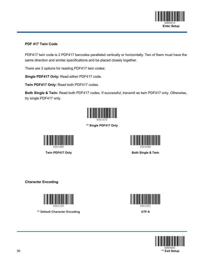
Enter Setup
95 ** Exit Setup
PDF 417 Twin Code
PDF417 twin code is 2 PDF417 barcodes paralleled vertically or horizontally. Two of them must have the same direction and similar specifications and be placed closely together.
There are 3 options for reading PDF417 twin codes:
Single PDF417 Only: Read either PDF417 code.
Twin PDF417 Only: Read both PDF417 codes.
Both Single & Twin: Read both PDF417 codes. If successful, transmit as twin PDF417 only. Otherwise, try single PDF417 only.
** Single PDF417 Only
Twin PDF417 Only
Both Single & Twin
Character Encoding
** Default Character Encoding
UTF-8
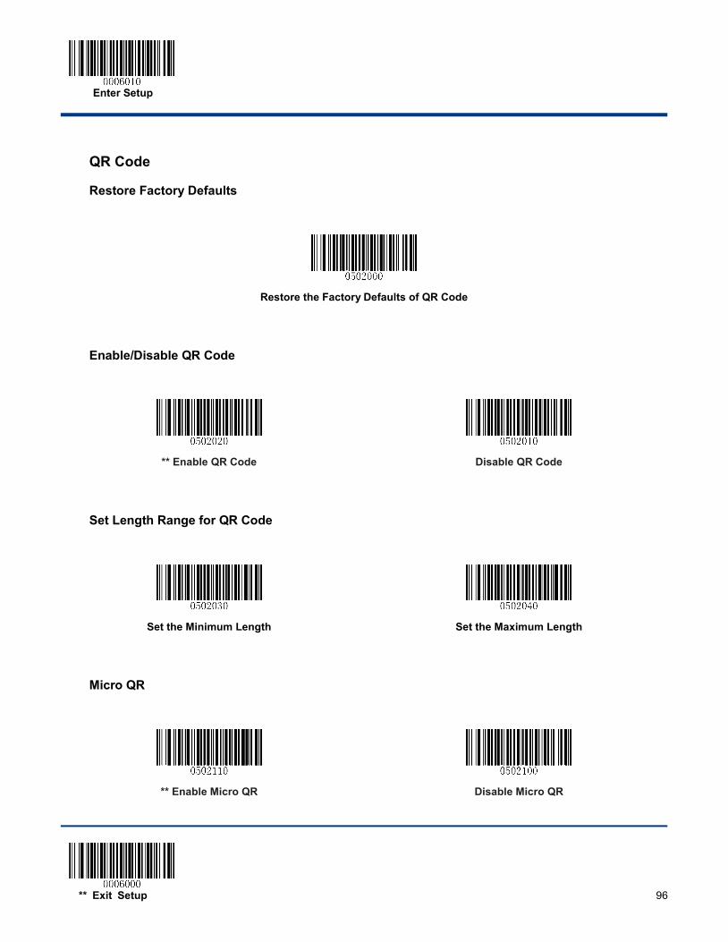
Enter Setup
** Exit Setup 96
QR Code
Restore Factory Defaults
Restore the Factory Defaults of QR Code
Enable/Disable QR Code
** Enable QR Code
Disable QR Code
Set Length Range for QR Code
Set the Minimum Length
Set the Maximum Length
Micro QR
** Enable Micro QR
Disable Micro QR
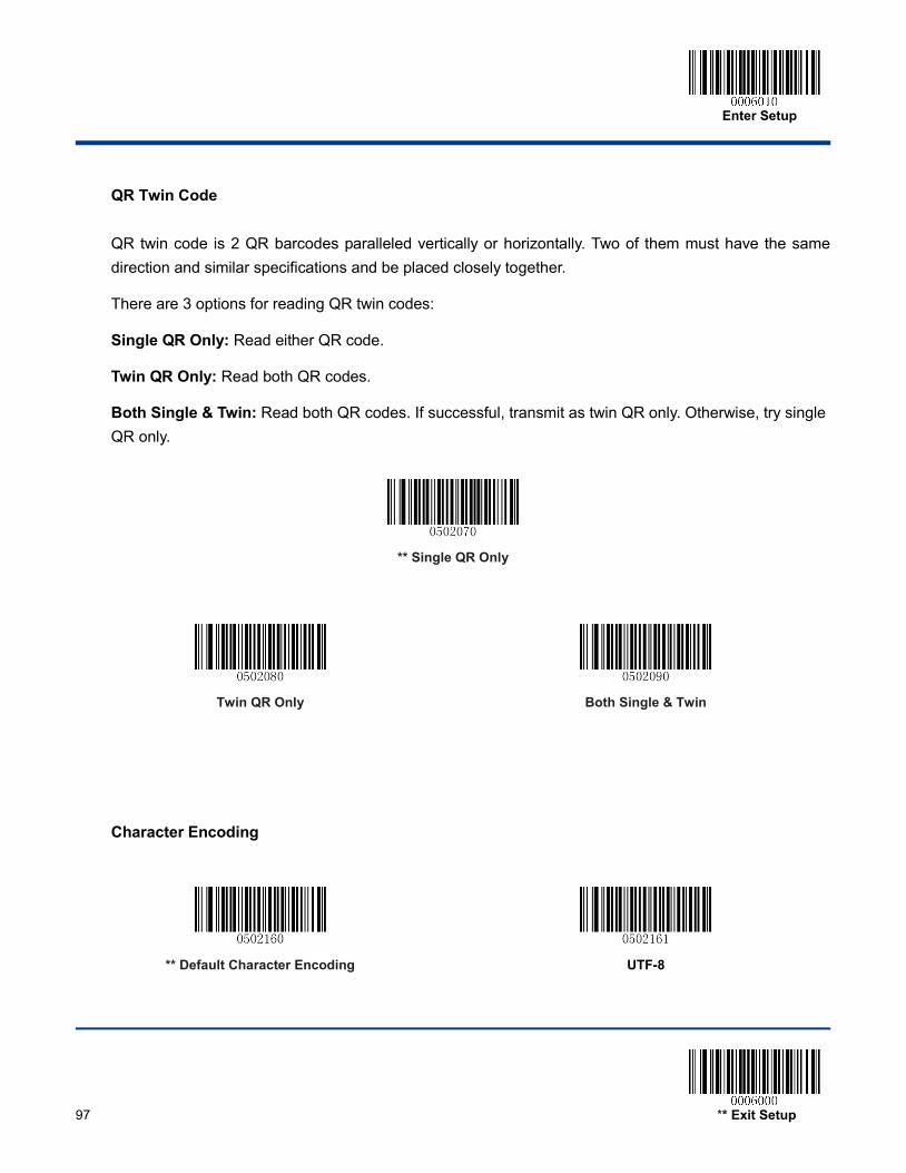
Enter Setup
97 ** Exit Setup
QR Twin Code
QR twin code is 2 QR barcodes paralleled vertically or horizontally. Two of them must have the same direction and similar specifications and be placed closely together.
There are 3 options for reading QR twin codes:
Single QR Only: Read either QR code.
Twin QR Only: Read both QR codes.
Both Single & Twin: Read both QR codes. If successful, transmit as twin QR only. Otherwise, try single QR only.
** Single QR Only
Twin QR Only
Both Single & Twin
Character Encoding
** Default Character Encoding
UTF-8
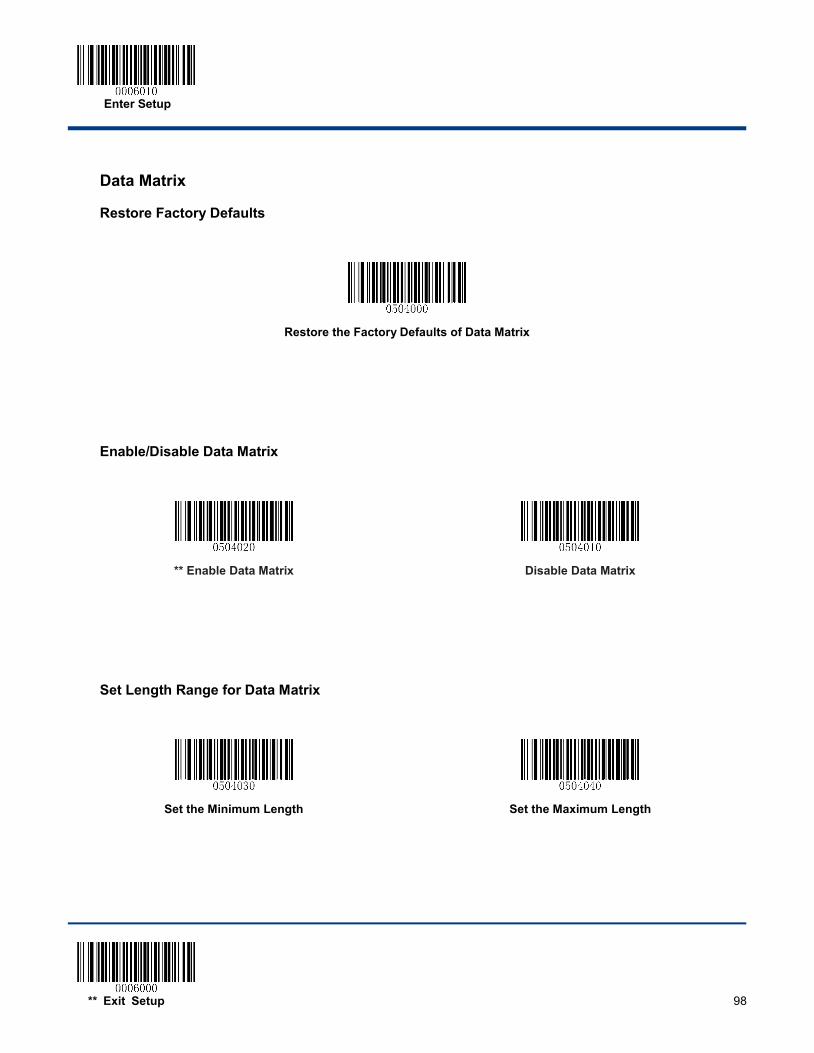
Enter Setup
** Exit Setup 98
Data Matrix
Restore Factory Defaults
Restore the Factory Defaults of Data Matrix
Enable/Disable Data Matrix
** Enable Data Matrix
Disable Data Matrix
Set Length Range for Data Matrix
Set the Minimum Length
Set the Maximum Length

Enter Setup
99 ** Exit Setup
Rectangular Barcode
** Enable Rectangular Barcode
Disable Rectangular Barcode
Mirror Image
** Decode Mirror Images
Do Not Decode Mirror Images
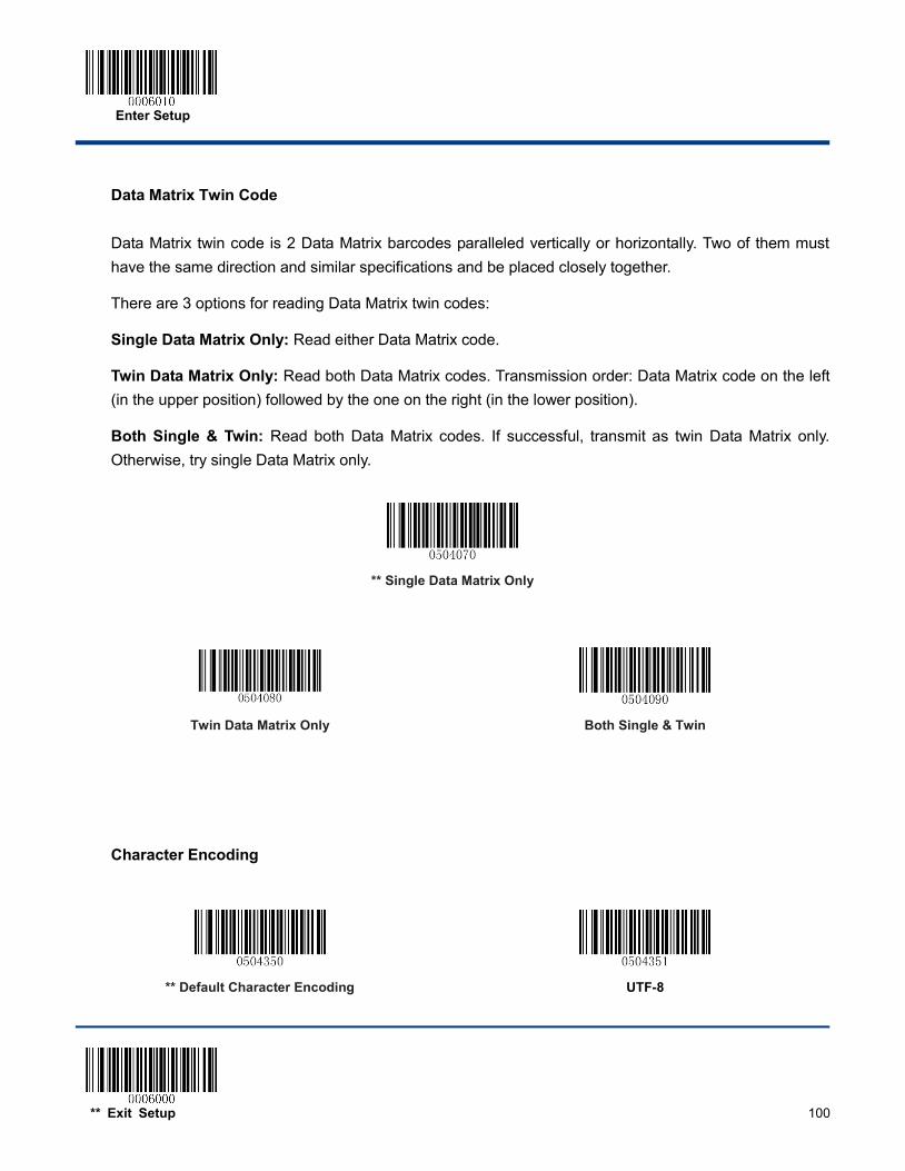
Enter Setup
** Exit Setup 100
Data Matrix Twin Code
Data Matrix twin code is 2 Data Matrix barcodes paralleled vertically or horizontally. Two of them must have the same direction and similar specifications and be placed closely together.
There are 3 options for reading Data Matrix twin codes:
Single Data Matrix Only: Read either Data Matrix code.
Twin Data Matrix Only: Read both Data Matrix codes. Transmission order: Data Matrix code on the left (in the upper position) followed by the one on the right (in the lower position).
Both Single & Twin: Read both Data Matrix codes. If successful, transmit as twin Data Matrix only. Otherwise, try single Data Matrix only.
** Single Data Matrix Only
Twin Data Matrix Only
Both Single & Twin
Character Encoding
** Default Character Encoding
UTF-8
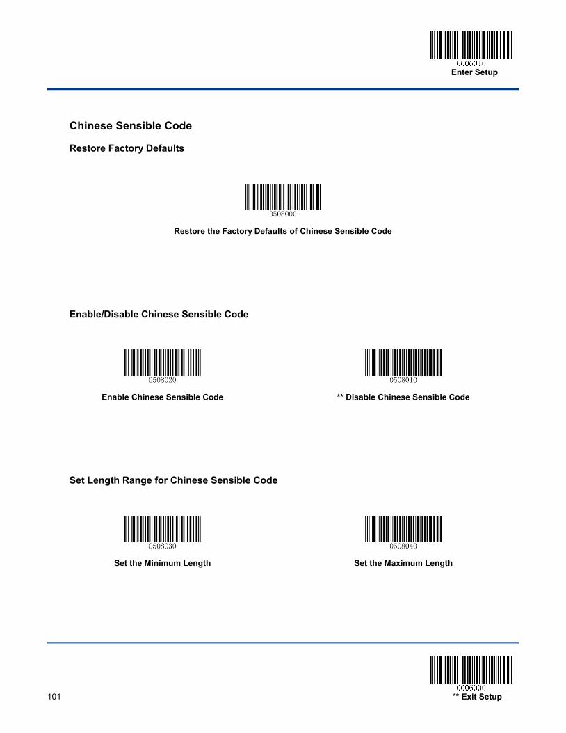
Enter Setup
101 ** Exit Setup
Chinese Sensible Code
Restore Factory Defaults
Restore the Factory Defaults of Chinese Sensible Code
Enable/Disable Chinese Sensible Code
Enable Chinese Sensible Code
** Disable Chinese Sensible Code
Set Length Range for Chinese Sensible Code
Set the Minimum Length
Set the Maximum Length
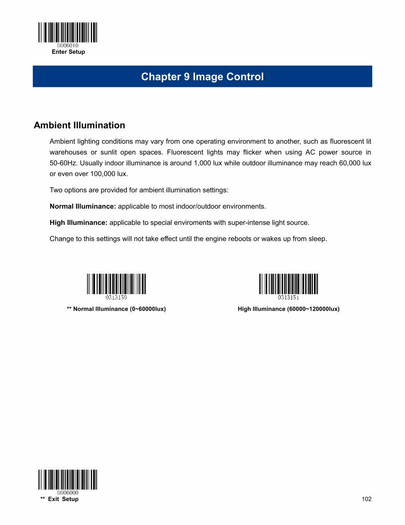
Enter Setup
** Exit Setup 102
Chapter 9 Image Control
Ambient Illumination Ambient lighting conditions may vary from one operating environment to another, such as fluorescent lit warehouses or sunlit open spaces. Fluorescent lights may flicker when using AC power source in 50-60Hz. Usually indoor illuminance is around 1,000 lux while outdoor illuminance may reach 60,000 lux or even over 100,000 lux.
Two options are provided for ambient illumination settings:
Normal Illuminance: applicable to most indoor/outdoor environments.
High Illuminance: applicable to special enviroments with super-intense light source.
Change to this settings will not take effect until the engine reboots or wakes up from sleep.
** Normal Illuminance (0~60000lux)
High Illuminance (60000~120000lux)
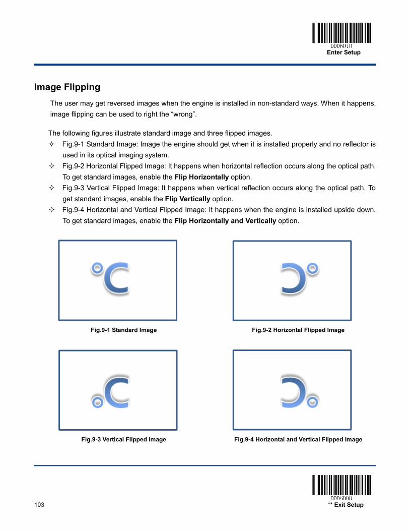
Enter Setup
103 ** Exit Setup
Image Flipping The user may get reversed images when the engine is installed in non-standard ways. When it happens, image flipping can be used to right the “wrong”.
The following figures illustrate standard image and three flipped images. Fig.9-1 Standard Image: Image the engine should get when it is installed properly and no reflector is
used in its optical imaging system. Fig.9-2 Horizontal Flipped Image: It happens when horizontal reflection occurs along the optical path.
To get standard images, enable the Flip Horizontally option. Fig.9-3 Vertical Flipped Image: It happens when vertical reflection occurs along the optical path. To
get standard images, enable the Flip Vertically option. Fig.9-4 Horizontal and Vertical Flipped Image: It happens when the engine is installed upside down.
To get standard images, enable the Flip Horizontally and Vertically option.
Fig.9-1 Standard Image Fig.9-2 Horizontal Flipped Image
Fig.9-3 Vertical Flipped Image Fig.9-4 Horizontal and Vertical Flipped Image
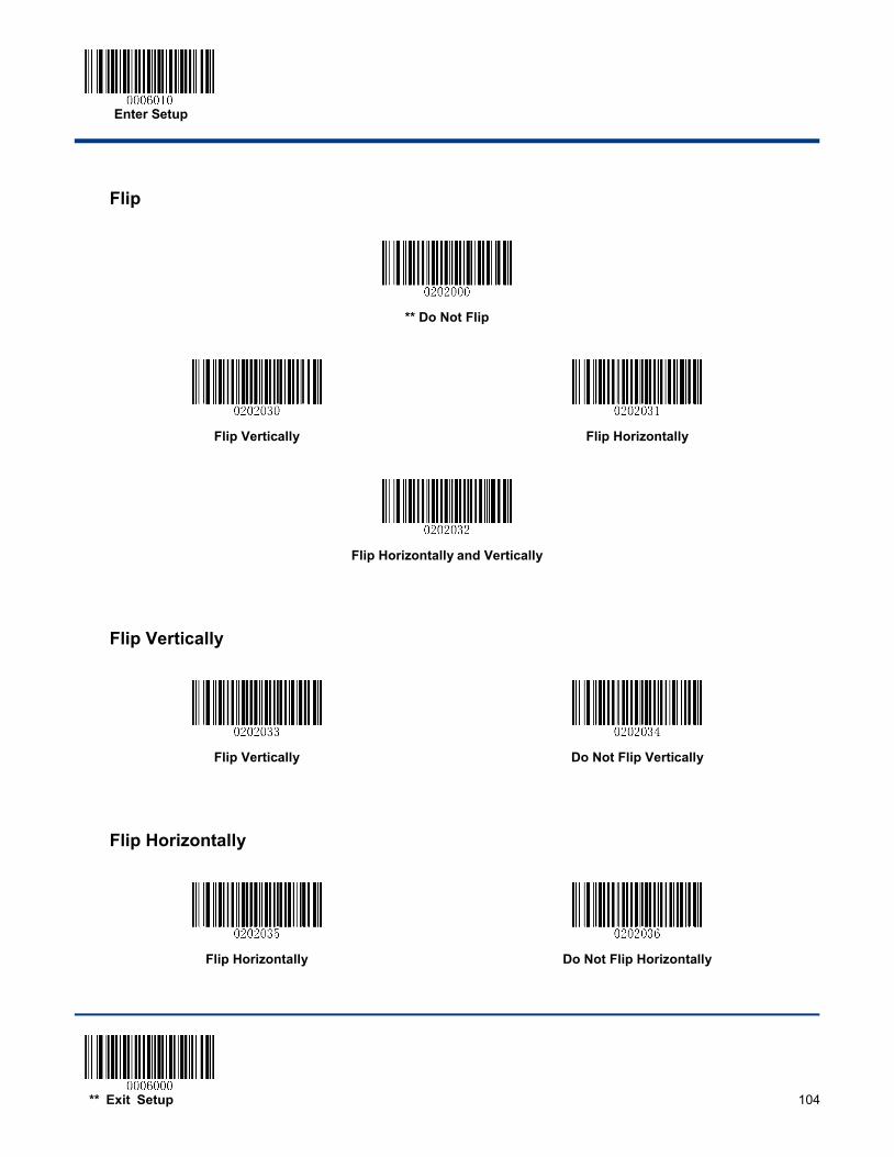
Enter Setup
** Exit Setup 104
Flip
** Do Not Flip
Flip Vertically
Flip Horizontally
Flip Horizontally and Vertically
Flip Vertically
Flip Vertically
Do Not Flip Vertically
Flip Horizontally
Flip Horizontally
Do Not Flip Horizontally
105
Chapter 10 Troubleshooting
FAQ
Problem: Some barcodes cannot be read.
Solution: 1. Find out the barcode type and verify that the barcode type is enabled. If the barcode parameters
include check digit verification, select the Disable option. 2. If you do not know the barcode type, enable all symbologies. 3. If they are inverse barcodes (bright images on a dark background), enable the Video Reverse feature.
Problem: Incorrect output.
Solution: 1. If this problem happens to all barcodes and additional characters appear before/after barcode data,
disable all prefix/suffix. 2. If this problem only happens to some barcodes and matches one of the following situations: a) incomplete barcode data: Enable the check digit verification. b) both the first and last characters are asterisks (*): Disable the transmission of start/stop characters of
Code 39. c) “a” transmitted as “+A”: Enable Code 39 Full ASCII.
Problem: Barcodes can be read, but cannot be displayed.
Solution: Verify that the serial port parameter (such as baud rate, data bit and stop bit) settings match the host requirements.

106
Problem: Illumination and aiming beams are OFF.
Solution: 1. Verify that the engine is properly powered up. 2. Send “?” to the engine. If the engine returns a reply of “!”, then send programming commands to turn
on illumination and aimer.
Problem: Carriage Return/Line Feed settings.
Solution: See the “Terminating Character Suffix” section in Chapter 7.

107
Appendix
Appendix 1: Factory Defaults Table Parameter Factory Default Remark
Programming Barcode
Barcode Programming Disabled
Programming Barcode Data Do not send
Communication Settings
Normal Mode (TTL-232 & USB supported)
Enabled Power-Saving Mode: Only TTL-232 supported
TTL-232
Baud Rate 9600
Parity Check None
Data Bit 8
Stop Bit 1
Hardware Flow Control No flow control
HID-KBW (optional)
Polling Rate 1ms
USB Country Keyboard Type U.S.
Convert Case No conversion
Inter-Keystroke Delay 10ms
Beep on Unknown Character Do not beep
Emulate ALT + Keypad Disabled
Function Key Mapping Disabled
Emulate Numeric Keypad Disabled
Code Page Windows 1252 (Latin I)
Scan Mode
Scan Mode Trigger mode Options: Batch mode, Trigger mode, Sense mode, Continuous mode.
Trigger Mode
Decode Session Timeout 3,000ms Applicable to a Trigger mode, Sense mode, Continuous mode. 0~3,600,000ms
Trigger Condition Electric level
Auto Sleep Enabled
Time Period from Idle to Sleep 500ms 0~65,535ms
Timeout between Decodes (Same Barcode)
Disabled
1,500ms 0~65,535ms
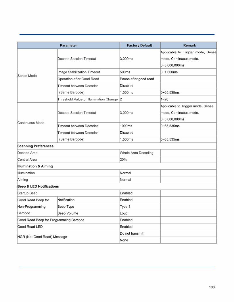
108
Parameter Factory Default Remark
Sense Mode
Decode Session Timeout 3,000ms
Applicable to Trigger mode, Sense
mode, Continuous mode.
0~3,600,000ms
Image Stabilization Timeout 500ms 0~1,600ms
Operation after Good Read Pause after good read
Timeout between Decodes
(Same Barcode)
Disabled
1,500ms 0~65,535ms
Threshold Value of Illumination Change 2 1~20
Continuous Mode
Decode Session Timeout 3,000ms
Applicable to Trigger mode, Sense
mode, Continuous mode.
0~3,600,000ms
Timeout between Decodes 1000ms 0~65,535ms
Timeout between Decodes
(Same Barcode)
Disabled
1,500ms 0~65,535ms
Scanning Preferences
Decode Area Whole Area Decoding
Central Area 20%
Illumination & Aiming
Illumination Normal
Aiming Normal
Beep & LED Notifications
Startup Beep Enabled
Good Read Beep for
Non-Programming
Barcode
Notification Enabled
Beep Type Type 3
Beep Volume Loud
Good Read Beep for Programming Barcode Enabled
Good Read LED Enabled
NGR (Not Good Read) Message Do not transmit
None
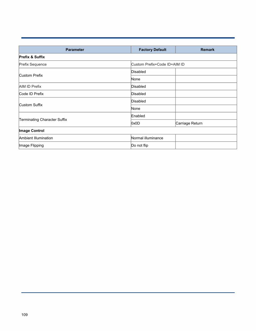
109
Parameter Factory Default Remark
Prefix & Suffix
Prefix Sequence Custom Prefix+Code ID+AIM ID
Custom Prefix Disabled
None
AIM ID Prefix Disabled
Code ID Prefix Disabled
Custom Suffix Disabled
None
Terminating Character Suffix Enabled
0x0D Carriage Return
Image Control
Ambient Illumination Normal illuminance
Image Flipping Do not flip
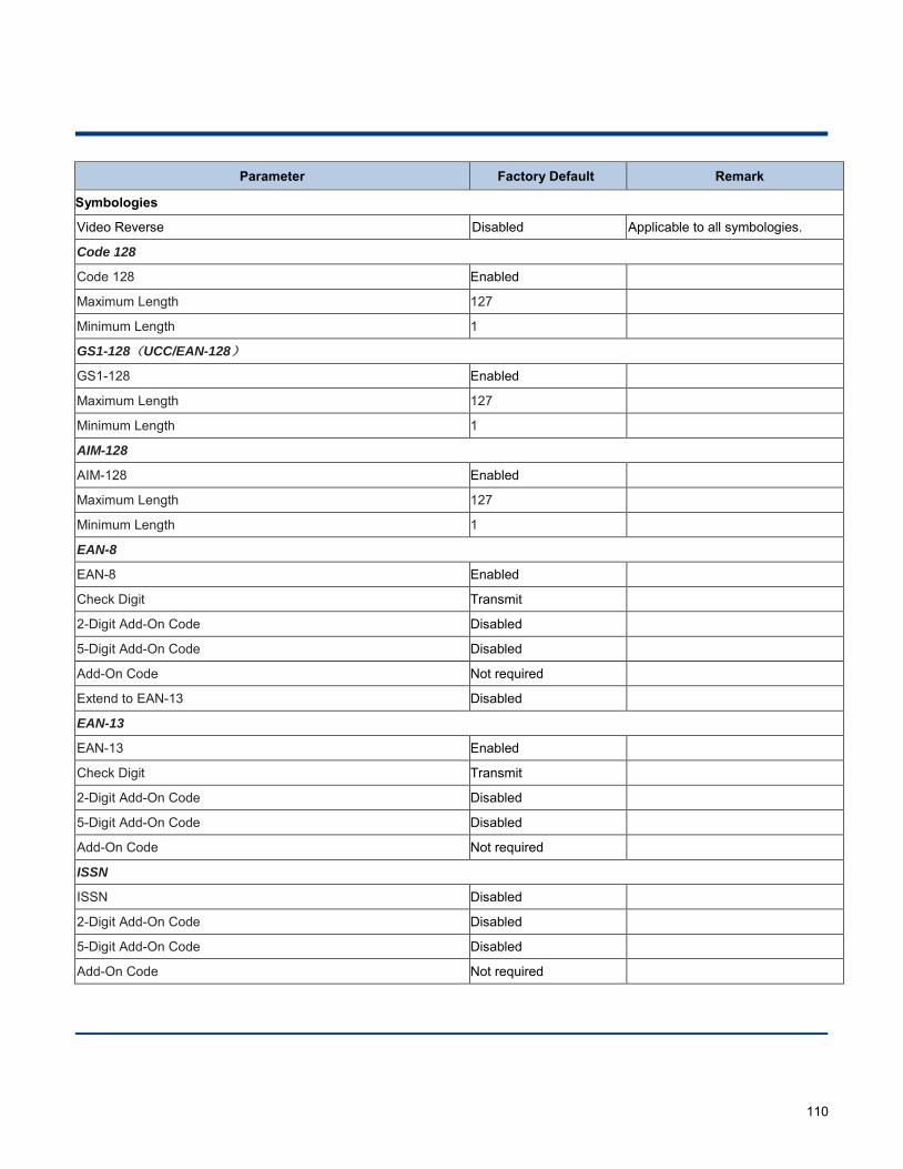
110
Parameter Factory Default Remark
Symbologies
Video Reverse Disabled Applicable to all symbologies.
Code 128
Code 128 Enabled
Maximum Length 127
Minimum Length 1
GS1-128(UCC/EAN-128)
GS1-128 Enabled
Maximum Length 127
Minimum Length 1
AIM-128
AIM-128 Enabled
Maximum Length 127
Minimum Length 1
EAN-8
EAN-8 Enabled
Check Digit Transmit
2-Digit Add-On Code Disabled
5-Digit Add-On Code Disabled
Add-On Code Not required
Extend to EAN-13 Disabled
EAN-13
EAN-13 Enabled
Check Digit Transmit
2-Digit Add-On Code Disabled
5-Digit Add-On Code Disabled
Add-On Code Not required
ISSN
ISSN Disabled
2-Digit Add-On Code Disabled
5-Digit Add-On Code Disabled
Add-On Code Not required
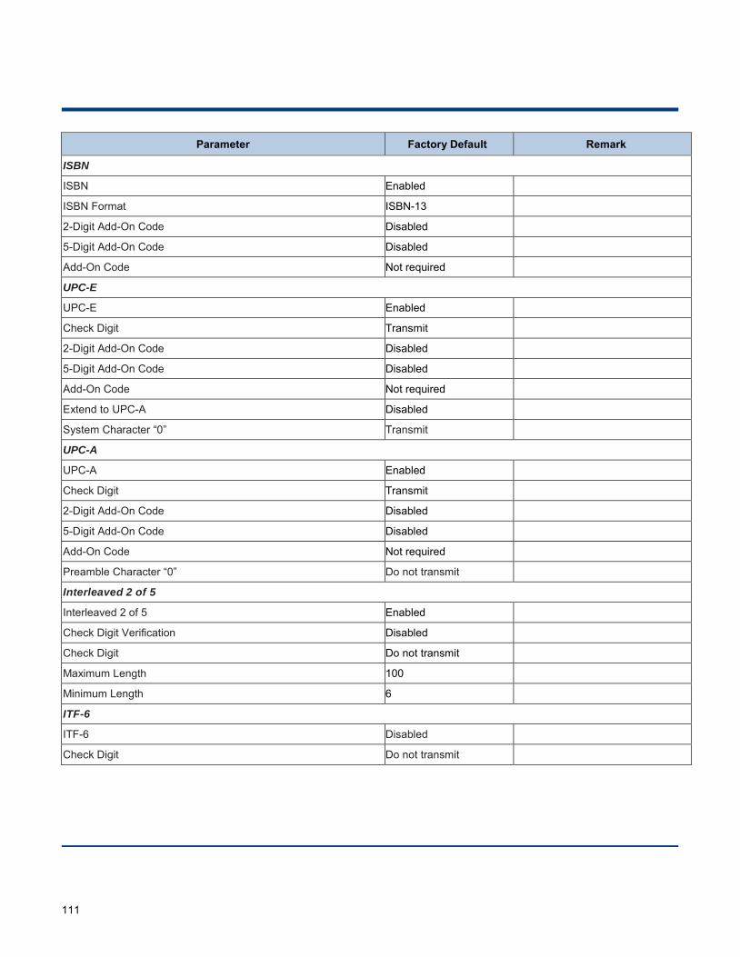
111
Parameter Factory Default Remark
ISBN
ISBN Enabled
ISBN Format ISBN-13
2-Digit Add-On Code Disabled
5-Digit Add-On Code Disabled
Add-On Code Not required
UPC-E
UPC-E Enabled
Check Digit Transmit
2-Digit Add-On Code Disabled
5-Digit Add-On Code Disabled
Add-On Code Not required
Extend to UPC-A Disabled
System Character “0” Transmit
UPC-A
UPC-A Enabled
Check Digit Transmit
2-Digit Add-On Code Disabled
5-Digit Add-On Code Disabled
Add-On Code Not required
Preamble Character “0” Do not transmit
Interleaved 2 of 5
Interleaved 2 of 5 Enabled
Check Digit Verification Disabled
Check Digit Do not transmit
Maximum Length 100
Minimum Length 6
ITF-6
ITF-6 Disabled
Check Digit Do not transmit
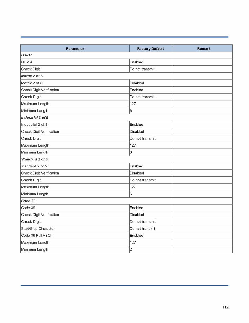
112
Parameter Factory Default Remark
ITF-14
ITF-14 Enabled
Check Digit Do not transmit
出
Matrix 2 of 5
Matrix 2 of 5 Disabled
Check Digit Verification Enabled
Check Digit Do not transmit
Maximum Length 127
Minimum Length 6
Industrial 2 of 5
Industrial 2 of 5 Enabled
Check Digit Verification Disabled
Check Digit Do not transmit
Maximum Length 127
Minimum Length 6
Standard 2 of 5
Standard 2 of 5 Enabled
Check Digit Verification Disabled
Check Digit Do not transmit
Maximum Length 127
Minimum Length 6
Code 39
Code 39 Enabled
Check Digit Verification Disabled
Check Digit Do not transmit
Start/Stop Character Do not transmit
Code 39 Full ASCII Enabled
Maximum Length 127
Minimum Length 2
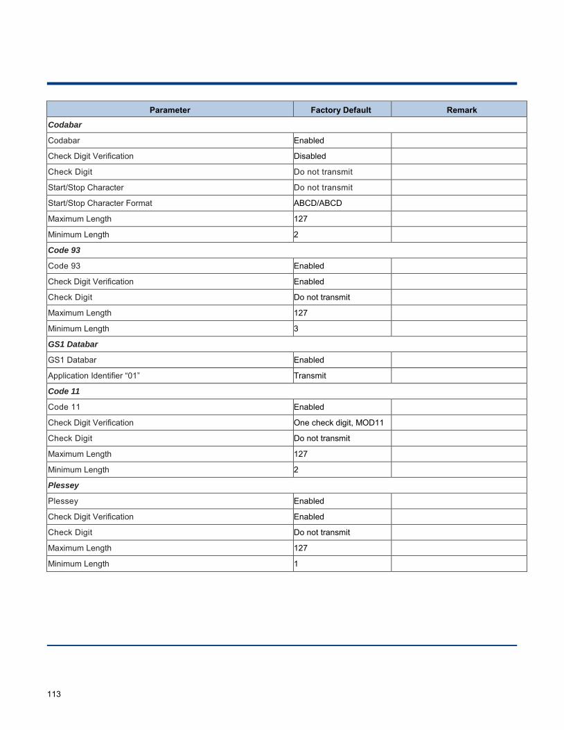
113
Parameter Factory Default Remark
Codabar
Codabar Enabled
Check Digit Verification Disabled
Check Digit Do not transmit
Start/Stop Character Do not transmit
Start/Stop Character Format ABCD/ABCD
Maximum Length 127
Minimum Length 2
Code 93
Code 93 Enabled
Check Digit Verification Enabled
Check Digit Do not transmit
Maximum Length 127
Minimum Length 3
GS1 Databar
GS1 Databar Enabled
Application Identifier “01” Transmit
Code 11
Code 11 Enabled
Check Digit Verification One check digit, MOD11
Check Digit Do not transmit
Maximum Length 127
Minimum Length 2
Plessey
Plessey Enabled
Check Digit Verification Enabled
Check Digit Do not transmit
Maximum Length 127
Minimum Length 1
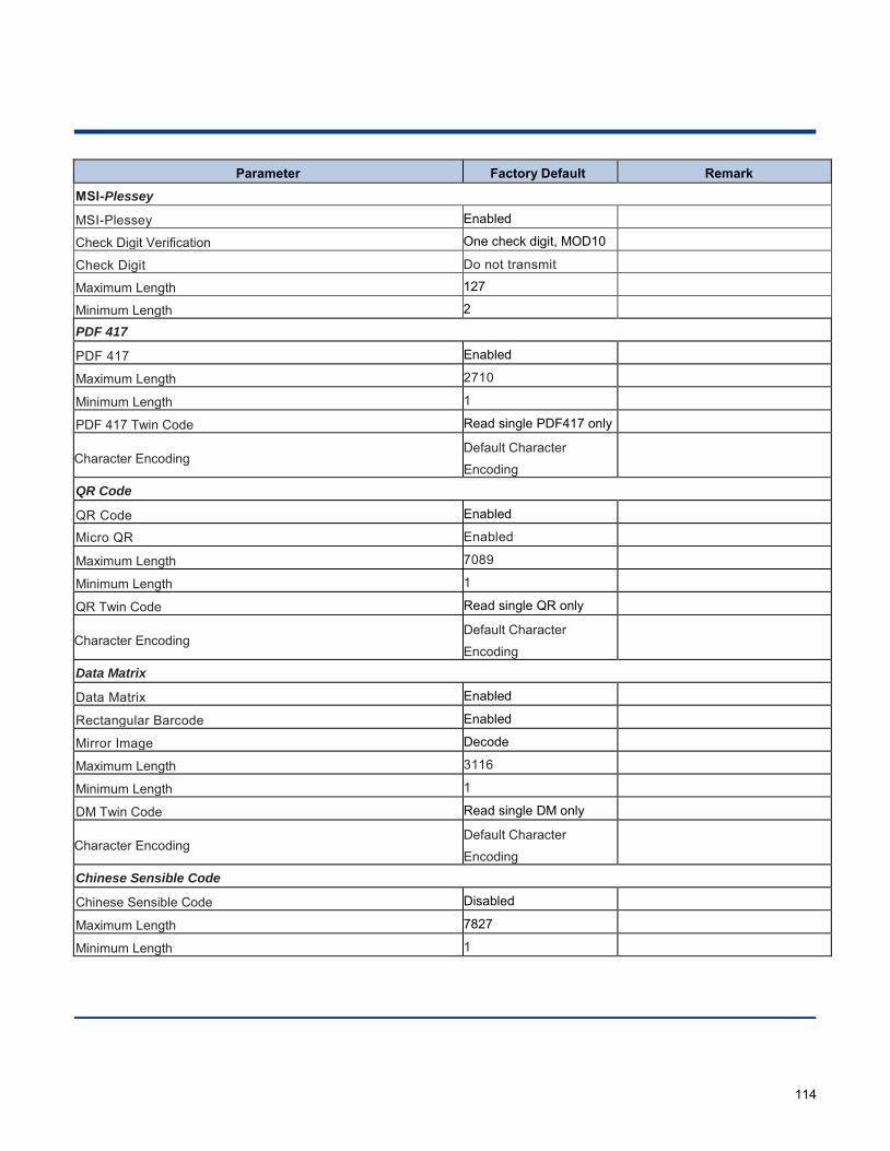
114
Parameter Factory Default Remark
MSI-Plessey
MSI-Plessey Enabled
Check Digit Verification One check digit, MOD10
Check Digit Do not transmit
Maximum Length 127
Minimum Length 2
PDF 417
PDF 417 Enabled
Maximum Length 2710
Minimum Length 1
PDF 417 Twin Code Read single PDF417 only
Character Encoding Default Character
Encoding
QR Code
QR Code Enabled
Micro QR Enabled
Maximum Length 7089
Minimum Length 1
QR Twin Code Read single QR only
Character Encoding Default Character
Encoding
Data Matrix
Data Matrix Enabled
Rectangular Barcode Enabled
Mirror Image Decode
Maximum Length 3116
Minimum Length 1
DM Twin Code Read single DM only
Character Encoding Default Character
Encoding
Chinese Sensible Code
Chinese Sensible Code Disabled
Maximum Length 7827
Minimum Length 1
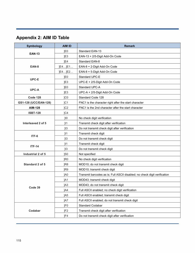
115
Appendix 2: AIM ID Table
Symbology AIM ID Remark
EAN-13 ]E0 Standard EAN-13
]E3 EAN-13 + 2/5-Digit Add-On Code
EAN-8
]E4 Standard EAN-8
]E4…]E1… EAN-8 + 2-Digit Add-On Code
]E4…]E2… EAN-8 + 5-Digit Add-On Code
UPC-E ]E0 Standard UPC-E
]E3 UPC-E + 2/5-Digit Add-On Code
UPC-A ]E0 Standard UPC-A
]E3 UPC-A + 2/5-Digit Add-On Code
Code 128 ]C0 Standard Code 128
GS1-128 (UCC/EAN-128) ]C1 FNC1 is the character right after the start character
AIM-128 ]C2 FNC1 is the 2nd character after the start character
ISBT-128 ]C4
Interleaved 2 of 5
]I0 No check digit verification
]I1 Transmit check digit after verification
]I3 Do not transmit check digit after verification
ITF-6 ]I1 Transmit check digit
]I3 Do not transmit check digit
ITF-14 ]I1 Transmit check digit
]I3 Do not transmit check digit
Industrial 2 of 5 ]S0 Not specified
Standard 2 of 5
]R0 No check digit verification
]R8 MOD10; do not transmit check digit
]R9 MOD10; transmit check digit
Code 39
]A0 Transmit barcodes as is; Full ASCII disabled; no check digit verification
]A1 MOD43; transmit check digit
]A3 MOD43; do not transmit check digit
]A4 Full ASCII enabled; no check digit verification
]A5 Full ASCII enabled; transmit check digit
]A7 Full ASCII enabled; do not transmit check digit
Codabar
]F0 Standard Codabar
]F2 Transmit check digit after verification
]F4 Do not transmit check digit after verification
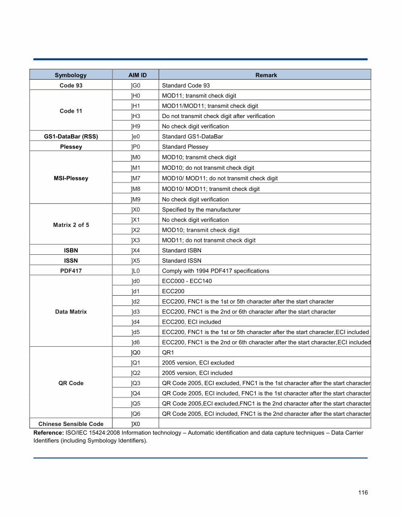
116
Symbology AIM ID Remark
Code 93 ]G0 Standard Code 93
Code 11
]H0 MOD11; transmit check digit
]H1 MOD11/MOD11; transmit check digit
]H3 Do not transmit check digit after verification
]H9 No check digit verification
GS1-DataBar (RSS) ]e0 Standard GS1-DataBar
Plessey ]P0 Standard Plessey
MSI-Plessey
]M0 MOD10; transmit check digit
]M1 MOD10; do not transmit check digit
]M7 MOD10/ MOD11; do not transmit check digit
]M8 MOD10/ MOD11; transmit check digit
]M9 No check digit verification
Matrix 2 of 5
]X0 Specified by the manufacturer
]X1 No check digit verification
]X2 MOD10; transmit check digit
]X3 MOD11; do not transmit check digit
ISBN ]X4 Standard ISBN
ISSN ]X5 Standard ISSN
PDF417 ]L0 Comply with 1994 PDF417 specifications
Data Matrix
]d0 ECC000 - ECC140
]d1 ECC200
]d2 ECC200, FNC1 is the 1st or 5th character after the start character
]d3 ECC200, FNC1 is the 2nd or 6th character after the start character
]d4 ECC200, ECI included
]d5 ECC200, FNC1 is the 1st or 5th character after the start character,ECI included
]d6 ECC200, FNC1 is the 2nd or 6th character after the start character,ECI included
QR Code
]Q0 QR1
]Q1 2005 version, ECI excluded
]Q2 2005 version, ECI included
]Q3 QR Code 2005, ECI excluded, FNC1 is the 1st character after the start character
]Q4 QR Code 2005, ECI included, FNC1 is the 1st character after the start character
]Q5 QR Code 2005,ECI excluded,FNC1 is the 2nd character after the start character
]Q6 QR Code 2005, ECI included, FNC1 is the 2nd character after the start character
Chinese Sensible Code ]X0 Reference: ISO/IEC 15424:2008 Information technology – Automatic identification and data capture techniques – Data Carrier Identifiers (including Symbology Identifiers).
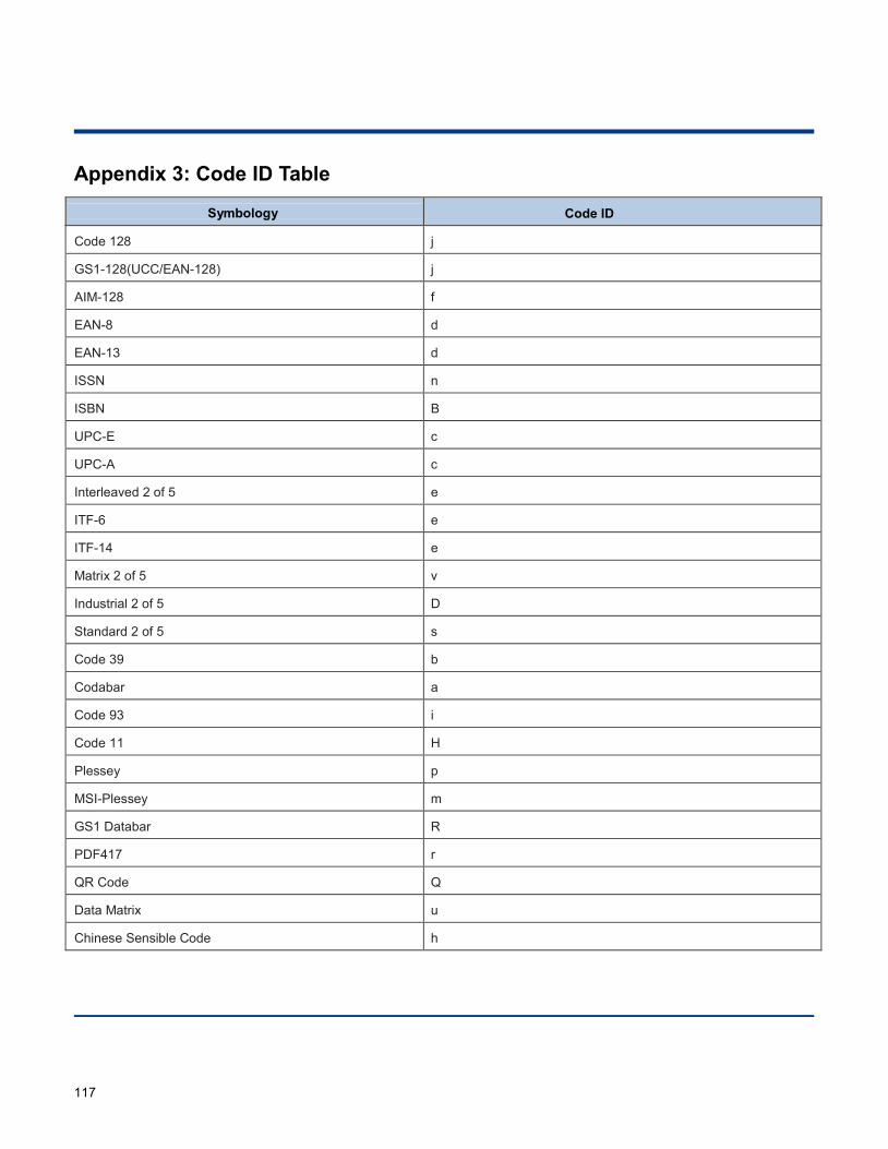
117
Appendix 3: Code ID Table
Symbology Code ID
Code 128 j
GS1-128(UCC/EAN-128) j
AIM-128 f
EAN-8 d
EAN-13 d
ISSN n
ISBN B
UPC-E c
UPC-A c
Interleaved 2 of 5 e
ITF-6 e
ITF-14 e
Matrix 2 of 5 v
Industrial 2 of 5 D
Standard 2 of 5 s
Code 39 b
Codabar a
Code 93 i
Code 11 H
Plessey p
MSI-Plessey m
GS1 Databar R
PDF417 r
QR Code Q
Data Matrix u
Chinese Sensible Code h
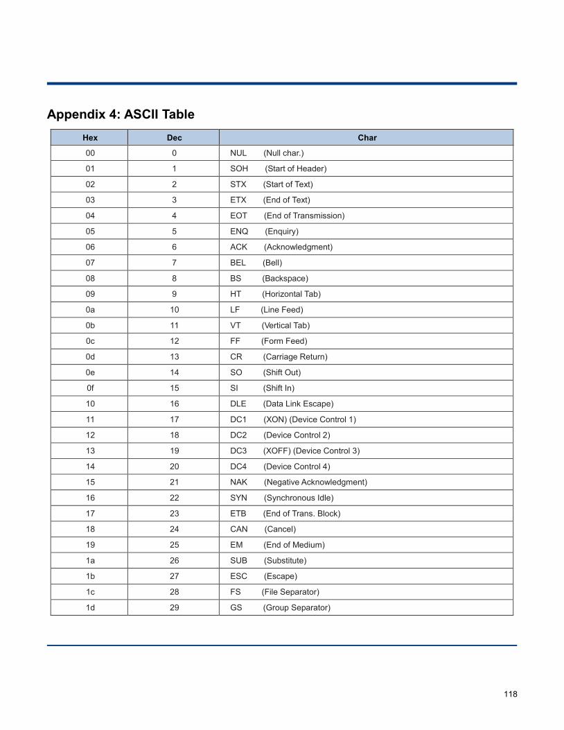
118
Appendix 4: ASCII Table Hex Dec Char
00 0 NUL (Null char.)
01 1 SOH (Start of Header)
02 2 STX (Start of Text)
03 3 ETX (End of Text)
04 4 EOT (End of Transmission)
05 5 ENQ (Enquiry)
06 6 ACK (Acknowledgment)
07 7 BEL (Bell)
08 8 BS (Backspace)
09 9 HT (Horizontal Tab)
0a 10 LF (Line Feed)
0b 11 VT (Vertical Tab)
0c 12 FF (Form Feed)
0d 13 CR (Carriage Return)
0e 14 SO (Shift Out)
0f 15 SI (Shift In)
10 16 DLE (Data Link Escape)
11 17 DC1 (XON) (Device Control 1)
12 18 DC2 (Device Control 2)
13 19 DC3 (XOFF) (Device Control 3)
14 20 DC4 (Device Control 4)
15 21 NAK (Negative Acknowledgment)
16 22 SYN (Synchronous Idle)
17 23 ETB (End of Trans. Block)
18 24 CAN (Cancel)
19 25 EM (End of Medium)
1a 26 SUB (Substitute)
1b 27 ESC (Escape)
1c 28 FS (File Separator)
1d 29 GS (Group Separator)
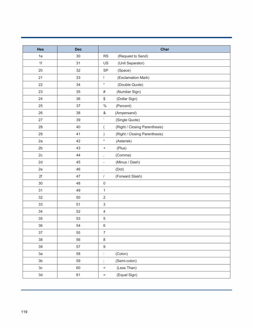
119
Hex Dec Char
1e 30 RS (Request to Send)
1f 31 US (Unit Separator)
20 32 SP (Space)
21 33 ! (Exclamation Mark)
22 34 " (Double Quote)
23 35 # (Number Sign)
24 36 $ (Dollar Sign)
25 37 % (Percent)
26 38 & (Ampersand)
27 39 ` (Single Quote)
28 40 ( (Right / Closing Parenthesis)
29 41 ) (Right / Closing Parenthesis)
2a 42 * (Asterisk)
2b 43 + (Plus)
2c 44 , (Comma)
2d 45 - (Minus / Dash)
2e 46 . (Dot)
2f 47 / (Forward Slash)
30 48 0
31 49 1
32 50 2
33 51 3
34 52 4
35 53 5
36 54 6
37 55 7
38 56 8
39 57 9
3a 58 : (Colon)
3b 59 ; (Semi-colon)
3c 60 < (Less Than)
3d 61 = (Equal Sign)
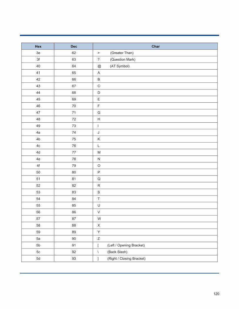
120
Hex Dec Char
3e 62 > (Greater Than)
3f 63 ? (Question Mark)
40 64 @ (AT Symbol)
41 65 A
42 66 B
43 67 C
44 68 D
45 69 E
46 70 F
47 71 G
48 72 H
49 73 I
4a 74 J
4b 75 K
4c 76 L
4d 77 M
4e 78 N
4f 79 O
50 80 P
51 81 Q
52 82 R
53 83 S
54 84 T
55 85 U
56 86 V
57 87 W
58 88 X
59 89 Y
5a 90 Z
5b 91 [ (Left / Opening Bracket)
5c 92 \ (Back Slash)
5d 93 ] (Right / Closing Bracket)
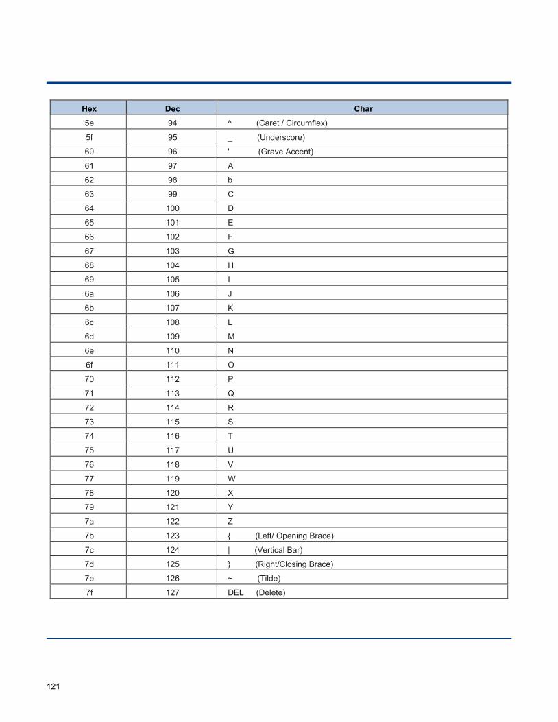
121
Hex Dec Char
5e 94 ^ (Caret / Circumflex)
5f 95 _ (Underscore)
60 96 ' (Grave Accent)
61 97 A
62 98 b
63 99 C
64 100 D
65 101 E
66 102 F
67 103 G
68 104 H
69 105 I
6a 106 J
6b 107 K
6c 108 L
6d 109 M
6e 110 N
6f 111 O
70 112 P
71 113 Q
72 114 R
73 115 S
74 116 T
75 117 U
76 118 V
77 119 W
78 120 X
79 121 Y
7a 122 Z
7b 123 { (Left/ Opening Brace)
7c 124 | (Vertical Bar)
7d 125 } (Right/Closing Brace)
7e 126 ~ (Tilde)
7f 127 DEL (Delete)

122
Appendix 5: Parameter Programming Examples
The following examples show you how to program parameters by scanning programming barcodes.
a. Program the Decode Session Timeout
Example: Set the decode session timeout to 1500ms 1. Scan the Enter Setup barcode. 2. Scan the Decode Session Timeout barcode. (See the “Decode Session Timeout” section in
Chapter 3) 3. Scan the numeric barcodes “1”, “5”, “0” and “0”. 4. Scan the Save barcode. 5. Scan the Exit Setup barcode. (If you still need to program other parameter/feature, skip this step.)
b. Program the Time Period from Idle to Sleep
Example: Set the time period from idle to sleep to 500ms 1. Scan the Enter Setup barcode. 2. Scan the Time Period from Idle to Sleep barcode. (See the “Auto Sleep” section in Chapter 3) 3. Scan the numeric barcodes “5”, “0” and “0”. 4. Scan the Save barcode. 5. Scan the Exit Setup barcode. (If you still need to program other parameter/feature, skip this step.)
c. Program the Image Stabilization Timeout
Example: Set the image stabilization timeout to 500ms 1. Scan the Enter Setup barcode. 2. Scan the Image Stabilization Timeout barcode. (See the “Image Stabilization Timeout” section in
Chapter 3) 3. Scan the numeric barcodes “5”, “0” and “0”. 4. Scan the Save barcode. 5. Scan the Exit Setup barcode. (If you still need to program other parameter/feature, skip this step.)
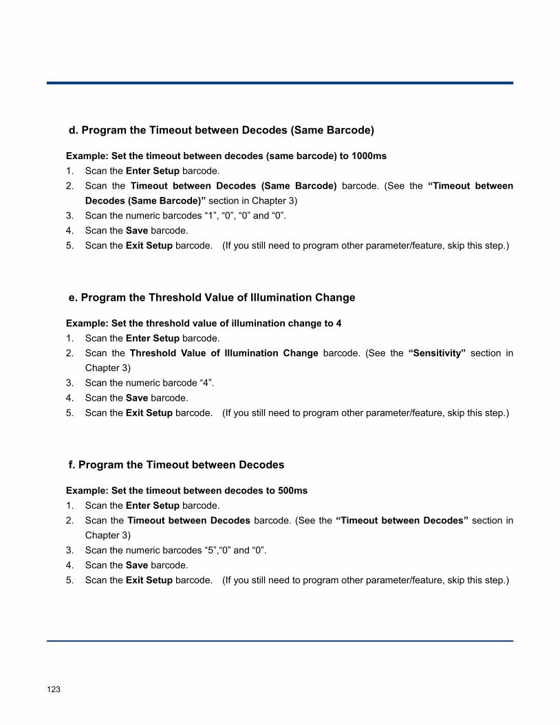
123
d. Program the Timeout between Decodes (Same Barcode)
Example: Set the timeout between decodes (same barcode) to 1000ms 1. Scan the Enter Setup barcode. 2. Scan the Timeout between Decodes (Same Barcode) barcode. (See the “Timeout between
Decodes (Same Barcode)” section in Chapter 3) 3. Scan the numeric barcodes “1”, “0”, “0” and “0”. 4. Scan the Save barcode. 5. Scan the Exit Setup barcode. (If you still need to program other parameter/feature, skip this step.)
e. Program the Threshold Value of Illumination Change
Example: Set the threshold value of illumination change to 4 1. Scan the Enter Setup barcode. 2. Scan the Threshold Value of Illumination Change barcode. (See the “Sensitivity” section in
Chapter 3) 3. Scan the numeric barcode “4”. 4. Scan the Save barcode. 5. Scan the Exit Setup barcode. (If you still need to program other parameter/feature, skip this step.)
f. Program the Timeout between Decodes
Example: Set the timeout between decodes to 500ms 1. Scan the Enter Setup barcode. 2. Scan the Timeout between Decodes barcode. (See the “Timeout between Decodes” section in
Chapter 3) 3. Scan the numeric barcodes “5”,“0” and “0”. 4. Scan the Save barcode. 5. Scan the Exit Setup barcode. (If you still need to program other parameter/feature, skip this step.)
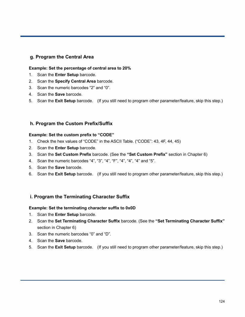
124
g. Program the Central Area
Example: Set the percentage of central area to 20% 1. Scan the Enter Setup barcode. 2. Scan the Specify Central Area barcode. 3. Scan the numeric barcodes “2” and “0”. 4. Scan the Save barcode. 5. Scan the Exit Setup barcode. (If you still need to program other parameter/feature, skip this step.)
h. Program the Custom Prefix/Suffix
Example: Set the custom prefix to “CODE” 1. Check the hex values of “CODE” in the ASCII Table. (“CODE”: 43, 4F, 44, 45) 2. Scan the Enter Setup barcode. 3. Scan the Set Custom Prefix barcode. (See the “Set Custom Prefix” section in Chapter 6) 4. Scan the numeric barcodes “4”, “3”, “4”, “F”, “4”, “4”, “4” and “5”. 5. Scan the Save barcode. 6. Scan the Exit Setup barcode. (If you still need to program other parameter/feature, skip this step.)
i. Program the Terminating Character Suffix
Example: Set the terminating character suffix to 0x0D 1. Scan the Enter Setup barcode. 2. Scan the Set Terminating Character Suffix barcode. (See the “Set Terminating Character Suffix”
section in Chapter 6) 3. Scan the numeric barcodes “0” and “D”. 4. Scan the Save barcode. 5. Scan the Exit Setup barcode. (If you still need to program other parameter/feature, skip this step.)
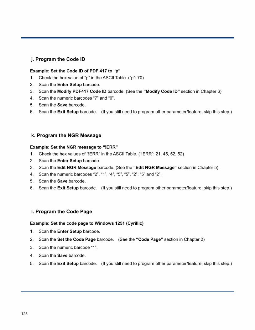
125
j. Program the Code ID
Example: Set the Code ID of PDF 417 to “p” 1. Check the hex value of “p” in the ASCII Table. (“p”: 70) 2. Scan the Enter Setup barcode. 3. Scan the Modify PDF417 Code ID barcode. (See the “Modify Code ID” section in Chapter 6) 4. Scan the numeric barcodes “7” and “0”. 5. Scan the Save barcode. 6. Scan the Exit Setup barcode. (If you still need to program other parameter/feature, skip this step.)
k. Program the NGR Message
Example: Set the NGR message to “!ERR” 1. Check the hex values of “!ERR” in the ASCII Table. (“!ERR”: 21, 45, 52, 52) 2. Scan the Enter Setup barcode. 3. Scan the Edit NGR Message barcode. (See the “Edit NGR Message” section in Chapter 5) 4. Scan the numeric barcodes “2”, “1”, “4”, “5”, “5”, “2”, “5” and “2”. 5. Scan the Save barcode. 6. Scan the Exit Setup barcode. (If you still need to program other parameter/feature, skip this step.)
l. Program the Code Page
Example: Set the code page to Windows 1251 (Cyrillic)
1. Scan the Enter Setup barcode.
2. Scan the Set the Code Page barcode. (See the “Code Page” section in Chapter 2)
3. Scan the numeric barcode “1”.
4. Scan the Save barcode.
5. Scan the Exit Setup barcode. (If you still need to program other parameter/feature, skip this step.)

126
m. Program the Length Range (Maximum/Minimum Lengths) for a Symbology
Note: If minimum length is set to be greater than maximum length, the engine only decodes barcodes with either the minimum or maximum length. If you only want to read barcodes with a specific length, set both minimum and maximum lengths to be that desired length.
Example: Set the engine to decode Code 128 barcodes containing between 8 and 12 characters
1. Scan the Enter Setup barcode.
2. Scan the Set the Minimum Length barcode. (See the “Set Length Range for Code 128” section in Chapter 7)
3. Scan the numeric barcode “8”.
4. Scan the Save barcode.
5. Scan the Set the Maximum Length barcode. (See the “Set Length Range for Code 128” section in Chapter 7)
6. Scan the numeric barcodes “1” and “2”.
7. Scan the Save barcode.
8. Scan the Exit Setup barcode. (If you still need to program other parameter/feature, skip this step.)
n. Program the Custom Inter-keystroke Delay
Example: Set the inter-keystroke delay to 15ms
1. Scan the Enter Setup barcode.
2. Scan the Custom Delay barcode. (See the “Inter-Keystroke Delay” section in Chapter 2)
3. Scan the numeric barcodes “1” and “5”.
4. Scan the Save barcode.
5. Scan the Exit Setup barcode. (If you still need to program other parameter/feature, skip this step.)
127
o. Program the engine to get proper output for Russian encoded with Windows 1251
1. Scan the Enter Setup barcode.
2. Scan the Set the Code Page barcode from the “Code Page” section in Chapter 2.
3. Scan the numeric barcode “1” from Appendix 6.
4. Scan the Save barcode from Appendix 7.
5. Scan the appropriate Default Character Encoding barcode according to the symbology your application needs from the “Character Encoding” section in Chapter 8.
6. Scan the Russia barcode from the “USB Country Keyboard Types” section in Chapter 2.
7. Scan the Mode 3 barcode from the “Emulate ALT+Keypad” section in Chapter 2.
8. Scan the Exit Setup barcode. (If you still need to program other parameter/feature, skip this step.)
p. Program the engine to get proper output for Russian encoded with UTF-8
1. Scan the Enter Setup barcode.
2. Scan the Set the Code Page barcode from the “Code Page” section in Chapter 2.
3. Scan the numeric barcode “1” from Appendix 6.
4. Scan the Save barcode from Appendix 7.
5. Scan the appropriate UTF-8 barcode according to the symbology your application needs from the “Character Encoding” section in Chapter 8.
6. Scan the Russia barcode from the “USB Country Keyboard Types” section in Chapter 2.
7. Scan the Mode 3 barcode from the “Emulate ALT+Keypad” section in Chapter 2.
8. Scan the Exit Setup barcode. (If you still need to program other parameter/feature, skip this step.)
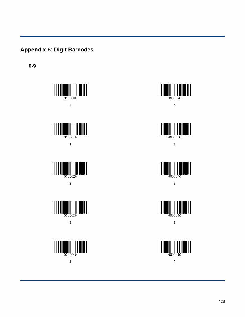
128
Appendix 6: Digit Barcodes 0-9
0
5
1
6
2
7
3
8
4
9
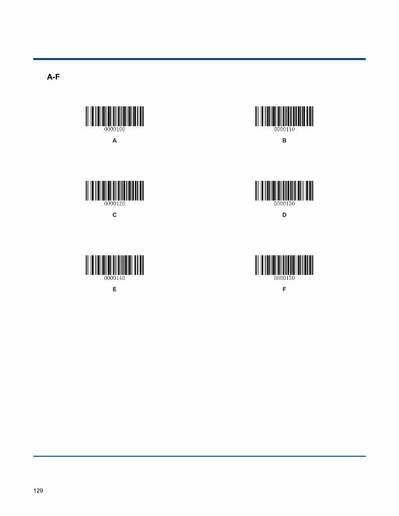
129
A-F
A
B
C
D
E
F
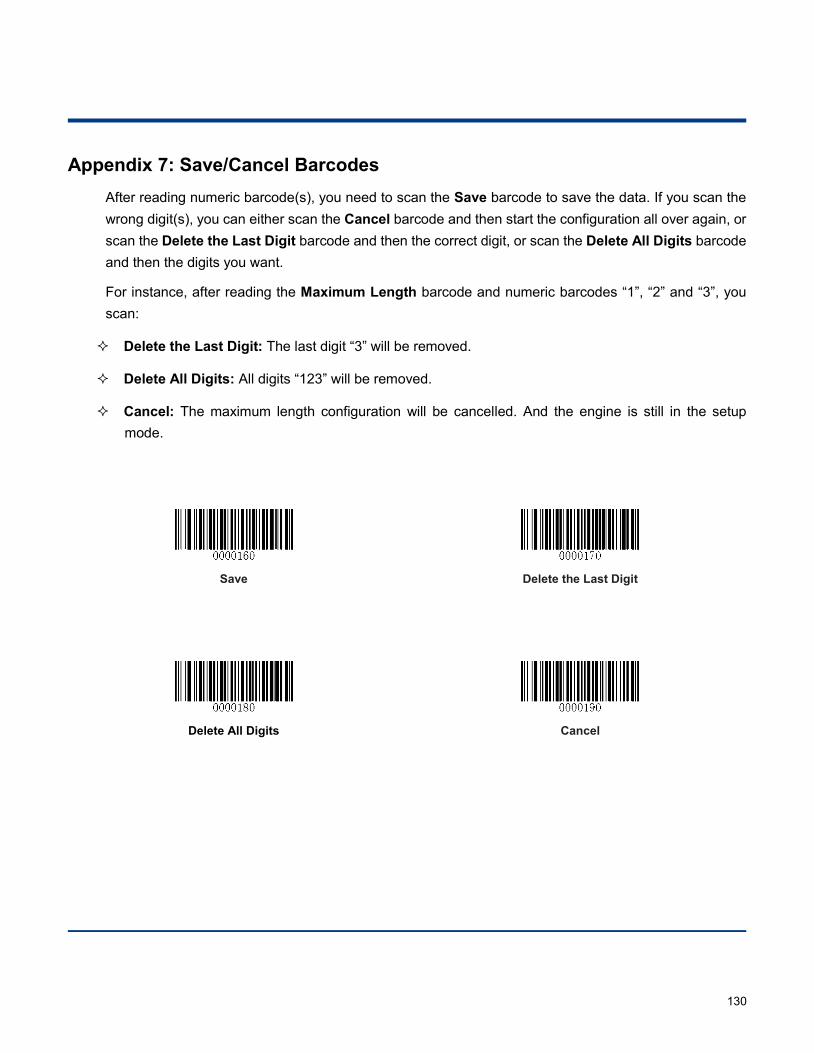
130
Appendix 7: Save/Cancel Barcodes After reading numeric barcode(s), you need to scan the Save barcode to save the data. If you scan the wrong digit(s), you can either scan the Cancel barcode and then start the configuration all over again, or scan the Delete the Last Digit barcode and then the correct digit, or scan the Delete All Digits barcode and then the digits you want.
For instance, after reading the Maximum Length barcode and numeric barcodes “1”, “2” and “3”, you scan:
Delete the Last Digit: The last digit “3” will be removed.
Delete All Digits: All digits “123” will be removed.
Cancel: The maximum length configuration will be cancelled. And the engine is still in the setup mode.
Save
Delete the Last Digit
Delete All Digits
Cancel
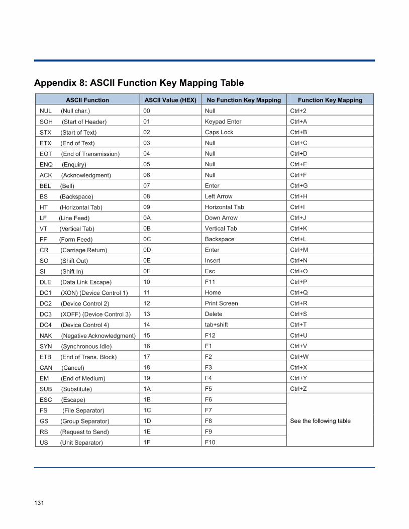
131
Appendix 8: ASCII Function Key Mapping Table ASCII Function ASCII Value (HEX) No Function Key Mapping Function Key Mapping
NUL (Null char.) 00 Null Ctrl+2
SOH (Start of Header) 01 Keypad Enter Ctrl+A
STX (Start of Text) 02 Caps Lock Ctrl+B
ETX (End of Text) 03 Null Ctrl+C
EOT (End of Transmission) 04 Null Ctrl+D
ENQ (Enquiry) 05 Null Ctrl+E
ACK (Acknowledgment) 06 Null Ctrl+F
BEL (Bell) 07 Enter Ctrl+G
BS (Backspace) 08 Left Arrow Ctrl+H
HT (Horizontal Tab) 09 Horizontal Tab Ctrl+I
LF (Line Feed) 0A Down Arrow Ctrl+J
VT (Vertical Tab) 0B Vertical Tab Ctrl+K
FF (Form Feed) 0C Backspace Ctrl+L
CR (Carriage Return) 0D Enter Ctrl+M
SO (Shift Out) 0E Insert Ctrl+N
SI (Shift In) 0F Esc Ctrl+O
DLE (Data Link Escape) 10 F11 Ctrl+P
DC1 (XON) (Device Control 1) 11 Home Ctrl+Q
DC2 (Device Control 2) 12 Print Screen Ctrl+R
DC3 (XOFF) (Device Control 3) 13 Delete Ctrl+S
DC4 (Device Control 4) 14 tab+shift Ctrl+T
NAK (Negative Acknowledgment) 15 F12 Ctrl+U
SYN (Synchronous Idle) 16 F1 Ctrl+V
ETB (End of Trans. Block) 17 F2 Ctrl+W
CAN (Cancel) 18 F3 Ctrl+X
EM (End of Medium) 19 F4 Ctrl+Y
SUB (Substitute) 1A F5 Ctrl+Z
ESC (Escape) 1B F6
See the following table
FS (File Separator) 1C F7
GS (Group Separator) 1D F8
RS (Request to Send) 1E F9
US (Unit Separator) 1F F10
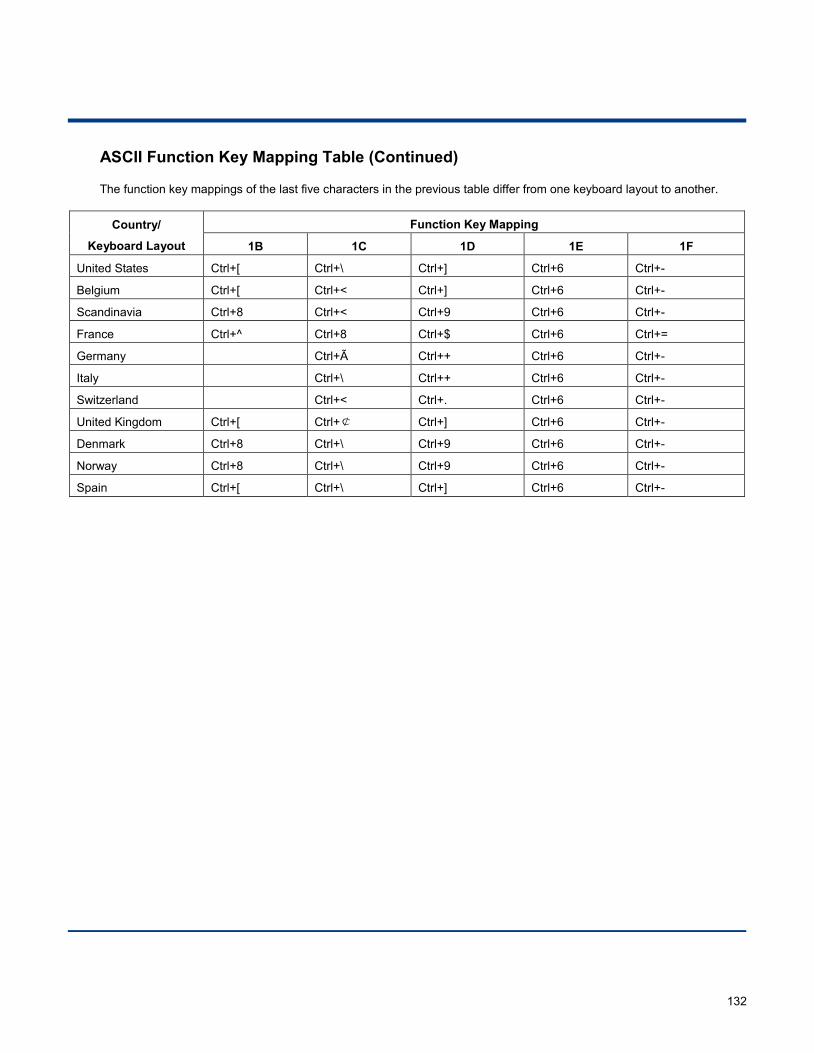
132
ASCII Function Key Mapping Table (Continued)
The function key mappings of the last five characters in the previous table differ from one keyboard layout to another.
Country/
Keyboard Layout
Function Key Mapping
1B 1C 1D 1E 1F
United States Ctrl+[ Ctrl+\ Ctrl+] Ctrl+6 Ctrl+-
Belgium Ctrl+[ Ctrl+< Ctrl+] Ctrl+6 Ctrl+-
Scandinavia Ctrl+8 Ctrl+< Ctrl+9 Ctrl+6 Ctrl+-
France Ctrl+^ Ctrl+8 Ctrl+$ Ctrl+6 Ctrl+=
Germany Ctrl+Ã Ctrl++ Ctrl+6 Ctrl+-
Italy Ctrl+\ Ctrl++ Ctrl+6 Ctrl+-
Switzerland Ctrl+< Ctrl+. Ctrl+6 Ctrl+-
United Kingdom Ctrl+[ Ctrl+¢ Ctrl+] Ctrl+6 Ctrl+-
Denmark Ctrl+8 Ctrl+\ Ctrl+9 Ctrl+6 Ctrl+-
Norway Ctrl+8 Ctrl+\ Ctrl+9 Ctrl+6 Ctrl+-
Spain Ctrl+[ Ctrl+\ Ctrl+] Ctrl+6 Ctrl+-
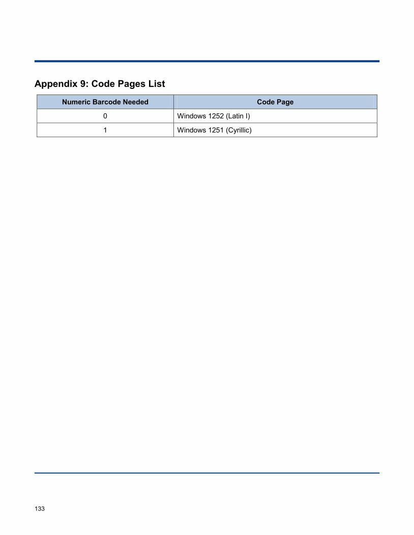
133
Appendix 9: Code Pages List
Numeric Barcode Needed Code Page
0 Windows 1252 (Latin I)
1 Windows 1251 (Cyrillic)

Newland EMEA+31 (0) 345 87 00 [email protected]
Newland D-A-CH+49 (0) 6182 [email protected]
Newland UK+44 (0) 1442 212 [email protected]
Newland Nordic+46 (0) 708 847 [email protected]
Newland Ibérica+34 (0) 93 303 74 [email protected]
Newland France+31 (0) 345 87 00 [email protected]
Newland Middle East+31 (0) 345 87 00 [email protected]
Newland South Africa+27 (0) 11 553 [email protected]
Newland Italy+39 (0) 342 056 [email protected]
Newland Russia+31 (0) 345 87 00 [email protected]
Newland Turkey & Iran+90 (0) 544 538 40 [email protected]@newland-id.com